drilling equipment and tooling offerings -...
TRANSCRIPT
SONIC EQUIPMENT AND TOOLINGDrilling Equipment and Tooling Offerings
Cop
yrig
ht ©
201
1 Bo
art L
ongy
ear.
All r
ight
s re
serv
ed.

Core Size Selection GuideDimensions
Core Barrel BitsCasing Shoes
3
9
33
41
47
63
57
TABLE OF CONTENTS
343638
10 20
42424242434445
48505252535354
646465666667
5858585960
Drill rodCore Barrel
Casing
LS™600Support Vehicle
Flange AdaptersBolt-on Sub-saverCasing Plug/RingCross-over Subs
AdaptersSub-savers
Retrieving Tools
Lexan Soil SamplerRod/Casing Handling Systems
Discrete Point SamplersIso-Flow Sampler
Miscellaneous ToolingConsumablesWrench Parts
Lubrication & CleaningTransit and Storage
Thread WearBox and Mid-body Wear
Loads and Deviated HolesSerialization/Lot Code
StabbingMake-up
Pre-loadingThread Introduction
Break-out/Fluid Seal
10LS™600 Sonic Rig
49Boart Longyear App
Copyright © 2012 Boart Longyear. All rights reserved.
Sonic System
Sonic Equipment
Rods, Core Barrel and Casing
Accessories
Miscellaneous
Wear and Care
Applications
Sonic Equipment
Sonic System
Bits and Casing Shoes
Rods, Core Barrel and Casing
Accessories
Miscellaneous
Applications
Wear and Care
9
3
23
33
41
47
57
63
4667
Sonic System DiagramsHow Sonic Works
Sonic Drilling ProcedureBenefits of Sonic
2324262830
Bits and Casing Shoes

2
Cop
yrig
ht ©
201
2 Bo
art L
ongy
ear.
All r
ight
s re
serv
ed.
22
3Copyright © 2012 Boart Longyear. All rights reserved. 3
SONIC SYSTEM4667
Sonic System DiagramsHow Sonic Works
Sonic Drilling ProcedureBenefits of Sonic

4
Sonic Head - Page 14
Flange Adapter - Page 39
Bolt-on Sub-saver - Page 39
Core Barrel Bit** - Page 25
Drill Rod - Page 34
Core Barrel - Page 33
Core Barrel Adapter - Page 40
4
Copyright ©
2012 Boart Longyear. All rights reserved.
TOOLING (COrE BArrEL AdvANCEMENT)During typical core barrel advancement, the core barrel is advanced 10 ft (3.05 m) using sonic frequencies. After the core barrel is in place, casing is sonically advanced over the core barrel. The core barrel is retrieved, producing a relatively undisturbed sample. *Drill rod, core barrels and related accessories are designed with right hand threads.**Core Size is determined by inner diameter of bit.

5
Casing - Page 30
5
Cop
yrig
ht ©
201
2 Bo
art L
ongy
ear.
All r
ight
s re
serv
ed.
Casing Shoe - Page 27
Casing Adapter- Page 40
TOOLING (CASING AdvANCEMENT)The diagram to the right shows typical casing advancement. A casing adapter is used to connect the sub-saver to the casing. Casing is sonically advanced over the core barrel to hole depth. *Casing and related accessories are designed with left hand threads.
Sonic Head - Page 14
Flange Adapter - Page 39
Bolt-on Sub-saver - Page 39

6 Copyright © 2012 Boart Longyear. All rights reserved.
SONIC drILLING PrOCEdUrEWhile there are several ways to drill using Sonic (depending upon site-specific conditions and project objectives), the most common means involves advancing a core barrel, which is overridden by a larger diameter drill string that cases the open bore hole and prevents collapse.
STEP 1 - COrE BArrEL AdvANCEMENTThe core barrel is advanced using sonic frequencies. When necessary this step can be performed using no fluids, air, or mud.
STEP 2 - CASING OvErrIdEAfter the core barrel is in place, casing is sonically advanced over the core barrel, protecting the bore hole’s integrity in loose unconsolidated ground.
STEP 3 - COrE rETrIEvALThe core barrel is retrieved, producing a relatively undisturbed sample with near 100% core recovery.
STEP 4 - rEPEAT COrE AdvANCEMENTSteps 1 - 3 are repeated to depth, producing a continuous core sample through unconsolidated formations with less than 1% deviation.
SONIC OSCILLATOr dIAGrAM
Rotating Element A (Rotates clock wise)
Rotating Element B (Rotates counter clock wise)
Drill pipe
High frequency wave lengths travelalong axis of drill pipe.
HOW SONIC drILLING WOrKSSonic is an advanced form of drilling which employs the use of high-frequency, resonant energy generated inside the Sonic head to advance a core barrel or casing into subsurface formations. During drilling, the resonant energy is transferred down the drill string to the bit face at various Sonic frequencies. Simultaneously rotating the drill string evenly distributes the energy and impact at the bit face.
The resonant energy is generated inside the Sonic head by two counter-rotating weights. A pneumatic isolation system inside the Sonic head prevents the resonant energy from transmitting to the drill rig and preferentially directs the energy down the drill string.
The driller controls the resonant energy generated by the Sonic head’s oscillator to match the formation being encountered to achieve maximum drilling productivity. When the resonant Sonic energy coincides with the natural frequency of the drill string, resonance occurs. This results in the maximum amount of energy being delivered to the face. At the same time, friction of the soil immediately adjacent to the entire drill string is substantially minimized, resulting in fast penetration rates.

7Copyright © 2012 Boart Longyear. All rights reserved. Sonic Core Sample
Superior Well ConstructionSonic drilling causes minimal disturbance to the surrounding bore hole wall, resulting in more efficient well development and performance.
FlexibilitySonic drilling advances a temporary outer casing as the bore hole is drilled, allowing more to be achieved within a single bore hole.
Risk MinimizationSonic drilling greatly reduces the risk of project failure due to unknown or difficult subsurface conditions.
BENEFITS OF SONICSuperior InformationSonic drilling provides a continuous, relatively undisturbed core sample of unparalleled quality and accuracy through any type of formation. With less than 1% drilling deviation, drillers know exactly where a sample is coming from.
Waste ReductionSonic drilling reduces waste by up to 80% relative to conventional methods, reducing the expensive disposal of contaminated waste.
PerformanceThe LS™600 is twice as fast as conventional overburden sampling methods.
< 1% drILL
dEvIATION
80% rEdUCEd
WASTE
2x FASTEr
BENEFITS OF SONIC

8 Copyright © 2012 Boart Longyear. All rights reserved.
Cop
yrig
ht ©
201
2 Bo
art L
ongy
ear.
All r
ight
s re
serv
ed.
8 LS™600 Sonic Drill - Poland

9Copyright © 2012 Boart Longyear. All rights reserved.
Boart Longyear is the industry’s largest fully integrated supplier of sonic drilling tools and equipment. Boart Longyear maintains the world’s largest fleet of sonic
drills, enabling in-house testing and development of tooling and equipment.
99
SONIC EQUIPMENT
1020
LS™600Support Vehicle

10 Copyright © 2012 Boart Longyear. All rights reserved.10
For more information on the LS™600 scan with a QR code reader on your smart phone.
LS™600 SONIC drILLFollowing its tradition of innovative drilling solutions, Boart Longyear is proud to offer the most advanced Sonic drill on the market. With innovative designs and patented technologies, the LS™600 drills deeper, produces more accurate samples and serves more markets than any other Sonic rig to date.
Advanced DesignThe LS600 features a pneumatic isolation system inside the head, preventing resonant energy from transmitting to the drill rig. This directs the maximum amount of energy down the drill string to the face of the bit for improved penetration rates. Its advanced design allows heads to last longer, drill faster and go deeper.
Greater DepthsA turbo-charged 6.6 liter Caterpillar® engine with 228 horsepower fuels the LS600’s Sonic head, allowing drillers to reach depths of up to 600 feet.
Superior InformationThe LS600 drills through and samples overburden and soft rock formations at or near 100% core recovery without the risk of refusal and without the use of fluids. In addition to producing a relatively undisturbed sample, the LS600 drills with as little as one percent deviation to depth enabling the driller to pinpoint exact sampling locations. More information with fewer holes — that’s the power of Sonic.
dIvErSE MArKETS SErvEdDue to its innate ability to penetrate fast, produce a nearly undisturbed sample to depth while using little or no fluid and its unique casing advancement system, the LS600 is ideal for several industries.
Mining The mining industry benefits from the LS600’s extremely accurate sampling of unconsolidated formations. Applications include:• Heap leach and tailing pad sampling• Monitoring well installation and water
sampling• Dewatering applications• Wireline sampling
EnvironmentalBy continually casing the bore hole and using little to no fluid, the LS600 eliminates the risk of cross contamination and is ideal for environmental and geotechnical work.
InfrastructureThe LS600 is ideal for infrastructure projects with its ability to drill precise straight holes with less than one degree of deviation at varying angles. In addition, it can be equipped with an SPT hammer for added versatility.
SONIC HEAd rEBUILd PrOGrAMBoart Longyear offers a service exchange program for the sonic drill head used on the LS™600. Heads are rebuilt using OEM parts and a warranty is provided with each replacement head.
Contact your local Boart Longyear sales representative for further information.

11Copyright © 2012 Boart Longyear. All rights reserved.
dEvELOPEd IN THE FIELdToday’s LS™600 is a culmination of nearly 20 years of hands-on experience, advanced engineering and field-testing. The LS600 is capable of drilling to depths of over 600 feet and offers casing diameters of up to 12 inches. In addition to its drilling capacity, the LS600 is track-mounted, offering improved site access.
Copyright © 2012 Boart Longyear. All rights reserved. 11LS™600 Sonic Drill - Cornwall, UK

12 Copyright © 2012 Boart Longyear. All rights reserved.
SIMPLE HYdrAULIC dESIGNThe manual hydraulic system is easy to operate and maintain.
INTErLOCKEd rOTATION BArrIErInterlocked rotation barrier slows rotation when barrier is open, providing additional operator safety.
rUBBEr TrACKSLow ground pressure rubber tracks avoid damage to asphalt and unstable ground.
GrEASE PISTON PrE-LOAd SYSTEMThe grease piston system maintains bearing pre-load with grease pressure. In the event of lost grease pressure, the head automatically shuts down to avoid damage.
rOBUST rOTATION ANd OSCILLATION ASSEMBLIESThe LS600’s rotation and oscillation assemblies are created using premium materials and advanced designs to improve life and performance.
drILL rOd ANd CASING MANAGEMENT SYSTEMThe LS™600 features a finger board for vertical storage of rods next to the mast, a patented spring-loaded Clam Shell for safe rod management to and from the finger board, a 90 degree head tilt for tripping of rods/casing and a full support vehicle system with a Gantry crane for presenting rods to the head. This advanced management system improves driller’s productivity and safety.
Copyright © 2011 Boart Longyear. All Rights Reserved. 12

13Copyright © 2012 Boart Longyear. All rights reserved. 13Support Vehicle

14
General Performance Rating
Metric U.S.
Drilling Depth*
*Depths based on normal drilling conditions. Varying ground conditions and drilling styles may vary results.
4.75 in (121 mm)6 in (152 mm)7 in (178 mm)8 in (203 mm)
9.25 in (235 mm)10.5 in (267 mm)
12 in (305 mm)
235 m183 m159 m137 m116 m101 m89 m
770 ft600 ft520 ft450 ft380 ft330 ft290 ft
Max Drilling Diameter 305 mm 12 in
Pull Back 67.5 kN 15,175 lbf
Down Force 40.5 kN 9,105 lbf
Max Casing Length 6 m 20 ft
Sonic Head
Metric U.S.
Drill Head Type BL - 150
Vibration Motors Fix displacement piston motors
Frequency range 0 - 150 Hz
Output Force @ 150 Hz 222 kN 50,000 lbs
Rotation Motor Charl-Lynn Gerotor hydraulic motor - reversible
Maximum Torque 3,660 Nm 2,700 ftlb
Rotation Speed 0 - 70 RPM
Prime Mover
Metric U.S.
Engine - Standard Unit Caterpillar C6.6, liquid cooled, turbo charged, charge air cooled engine.
Displacement 6.6 L 402.8 in3
Power (maximum) at 2,200 RPM 168 kW 225 hp
Emissions Stage III tier 3
Fuel Tank Capacity 156 L 41.2 gal
Engine - High Altitude Unit Caterpillar C7, liquid cooled, turbo charged, charge air cooled engine.
Displacement 7.2 L 439 in3
Power (maximum) at 2,200 RPM 223 kW 300 hp
Emissions Stage III tier 3
Fuel Tank Capacity 240 L 63.4 gal
LS™600 TECHNICAL INFOrMATION
Copyright © 2012 Boart Longyear. All rights reserved.

15Copyright © 2012 Boart Longyear. All rights reserved.
LS™600 TECHNICAL INFOrMATIONHydraulic System
Metric U.S.
Primary Pumps Variable Displacement axial piston close loop pumps
Max flow 2x240 lpm 2x63.4 gpm
Maximum Pressure (factory setting) 27.5 MPa 4,000 psi
Secondary Pumps Gear pumps
Max flow 114+114+60+60 Lpm 30+30+15+15 gpm
Maximum pressure (factory setting) 20.5 MPa 3,000 psi
Auxiliary Pump Gear pumps
Max flow 60+114+114+35 Lpm 15+30+30+9 gpm
Maximum pressure (factory setting) 20.5 MPa 3,000 psiHydraulic Oil Tank Capacityopen loop 333 L 88 galHydraulic Oil Tank Capacityclose loop 208 L 55 gal
Drill Mast System
Metric U.S.
Overall Length
Drilling Angle 45° off horizontal to 90° vertical down
Rod Pull 6 m 20 ft
Head Tilt 0 - 90 Degrees
Drill Feed System
Metric U.S.
Feed stroke 7.47 m 24.5 ft
Feed pull 67.5 kN 15,175 lbf
Feed Thrust 40.5 kN 9,105 lbf
Feed speed back-fine 25 m/min 82 ft/min
Feed speed down-fine 42 m/min 138 ft/min
Feed speed back-fast 50 m/min 164 ft/min
Feed speed down-fast 84 m/min 275 ft/min
Drilling Angle 45° off horizontal to 90° vertical down

16 Copyright © 2012 Boart Longyear. All rights reserved.
Main Winch
Metric U.S.
Line Pull
Bare Drum 9,650 N 2,169 lb
Full Drum 7,145 N 1,606 lb
Rope speed
Bare Drum 41 m/min 134 ft/min
Full Drum 56 m/min 183 ft/min
Main line winch cable dia. 6 mm 1/4 in
Minimum breaking strength 23,90 kN 5373 lb
Rope length 65 m 213 ft
Wireline Hoist
Metric U.S.
Line Pull
Bare Drum 9,650 N 2,169 lb
Full Drum 7,145 N 1,606 lb
Rope speed
Bare Drum 41 m/min 134 ft/min
Full Drum 56 m/min 183 ft/min
Main line winch cable dia. 6 mm 1/4 in
Minimum breaking strength 23.9 kN 5,373 lb
Rope length 152 m 500 ft
Foot Clamp/Breakout System
Metric U.S.
Rod Clamps 2 (dual cylinders - top and bottom)Max clamping diameter (clamp/breakout tool) 305 mm 12 inRange of clamping diameter w/std jaws 76 mm - 267 mm 3 in - 10.5 inRange of clamping diameter w/ optional jaws (casing) 267 mm - 305 mm 10.5 in - 12 in
Clamping force 129 kN 29,000 lb
Max breaking torque 23 kNm 16,964 lbft
Max breaking angle 39°
Copyright © 2012 Boart Longyear. All rights reserved.
LS™600 TECHNICAL INFOrMATION

17Copyright © 2012 Boart Longyear. All rights reserved.Copyright © 2012 Boart Longyear. All rights reserved.
Undercarriage
Metric U.S.
Crawler - Standard Unit Morooka 1500VD
Max speed, 1st gear 7.6 km/h 4.7 m/h
Max speed, 2nd gear 11 km/h 6.8 m/h
Track width: 700 mm 27.5 in
Ground pressure 0.041 MPa 5.9 PSI
Crawler - High Attitude Unit Morooka 2200VD
Max speed, 1st gear 8 km/h 5 m/h
Max speed, 2st gear 12 km/h 7.5 m/h
Track width: 750 mm 29.5 in
Ground pressure 0.046 MPa 6.6 PSI
Compressor
Metric U.S.
Type Hydraulic driven piston type
Max flow 400 lpm 105 gpm
Max pressure 8 bar 115 PSI
Options
Mud Pump
Metric U.S.
Type Triplex FMC L1622BCD with Ball Valves
Max flow 190 lpm 50 gpm
Max pressure 60 bar 870 PSI
Tank capacity 1,135 L 300 gal
Grout Pump
Metric U.S.
Type Screw Pump, Moyno 3L6
Max flow 102 lpm 27 gpm
Max pressure 15 bar 225 PSI
Grout mixer tank capacity 52 L 14 gal
LS™600 TECHNICAL INFOrMATION

18 Copyright © 2012 Boart Longyear. All rights reserved.
Additional Options
Welder Generator
Metric U.S.
Type Hydraulic driven Getec
Generator
Voltage 120 V
Frequency 60 Hz
Power 4,000 W 5.36 hp
Welder
Current 200 A
Voltage 12 - 30 V
Duty cycle 68%
Welder Generator - European Version - Hydraulic driven Dynaset
Metric U.S.
Generator
Voltage 230 V / 400 V
Frequency 50 Hz
Power 230 V 3,500 W 4.7 hp
Power 400 V 6,500 W 8.7 hp
Welder
Current 180 A
Voltage 22 - 32 V
Duty cycle @180 A 50%
Duty cycle @110 A 100%
Autohammer (Standard Penetration Test)
Metric U.S.
Impact rate 1 - 30 blows/minute
Hammer size 63,5 kg 140 lb
Hammer drop height 762 mm 30 in
Max pressure 124 bar 1800 PSI
Max flow 60 lpm 15.9 gpm
All up weight 226 kg 498 lb
Certified Hammer efficiency 64 - 72% 64 - 72%
LS™600 TECHNICAL INFOrMATION

19Copyright © 2012 Boart Longyear. All rights reserved.
Measurements
Mast up - Drilling position
Wet Weight = 17,700 kg (39,000 lbs)Consisting of:Morooka undercarriage 1500VDHydraulic ModuleMain winch and wirelineHydraulic mast raisingSonic head type: BL - 150Base frameHydraulic leveling jacks / outriggersFoot clampsRod rack for vertical rod storageGrout pump + grout barrelCompressorWelder-generatorWater tank (dry)Hydraulic mud pump
Mast Down - Travel position
10.6 m (34 ft 9 in)
9.6 m (31 ft 4 in)
2.73 m (8 ft 11.5 in)
3.5 m (11 ft 6 in)
10.03 m (32 ft 11 in)
LS™600 TECHNICAL INFOrMATION

20 Copyright © 2012 Boart Longyear. All rights reserved.
Support Vehicle - (Standard) - Marooka 1500
Front/back
3.4 m (11 ft 1.4 in)
7.05 m (23 ft 1.6 in)
2.73 m (8 ft 11.5 in)
3.4 m (11 ft 1.4 in)
LS™600 TECHNICAL INFOrMATION
Metric U.S.
Prime Mover Cat 6.6 Tier III engine (168 kW - 225 hp @ 2,200 rpm)
Weight 11,570 kg +/- 10% (no rods) 25,507 lbs +/- 10% (no rods)
Axis distance 3,870 mm 12 ft 8.4 in
Width of track shoes 700 mm 2 ft 3.6 in
Max ground pressure 0.28 MPa - Loaded 40.6 PSI

21Copyright © 2012 Boart Longyear. All rights reserved.
Support Vehicle - (High Altitude) - Marooka 2200
Front/back
Copyright © 2012 Boart Longyear. All rights reserved.
3.52 m (11 ft 6.5 in)
7.66 m (25 ft 1.7 in)
3.84 m (12 ft 7.2 in)
3.52 m (11 ft 7 in)
LS™600 TECHNICAL INFOrMATION
Metric U.S.
Prime Mover Cat C7 Tier III engine (223 kW - 300 hp @ 2,200 rpm)
Weight 17,400 kg +/- 10% (no rods) 38,360 lbs +/- 10% (no rods)
Axis distance 3,840 mm 12 ft 7.2 in
Width of track shoes 750 mm 2 ft 5.5 in
Max ground pressure 0.4 MPa - Loaded 58 PSI

22 Copyright © 2012 Boart Longyear. All rights reserved.22 Sandstone Casing Shoe
23Copyright © 2012 Boart Longyear. All rights reserved.
242628 30
Core Size Selection GuideDimensions
Core Barrel Bits Casing Shoes
BITS ANd SHOESBoart Longyear’s core barrel bits and casing shoes use high-grade tungsten carbide inserts and premium steel for increased strength and toughness. Boart Longyear’s
state-of-the-art manufacturing techniques and facilities, coupled with its stringent quality control ensure each product produced meets the highest standard of quality.

24 Copyright © 2012 Boart Longyear. All rights reserved.
COrE SIZE SELECTION GUIdE
How Core Size is DeterminedCore sample size is determined by the inner diameter of the core barrel bit. The bit diameter subsequently determines the core barrel diamter. Outer-hole diameter is determined by casing size.
Core Size Selection GuideCore Size Core Barrel Bit Size
Size** 3.75 in(95.3 mm)
4.5 in(114.3 mm)
4.75 in(120.7 mm)
6 in(152.4 mm)
7 in(177.8 mm)
8 in(203.2 mm)
9 in(228.6 mm)
10.5 in(266.7 mm)
3 in(76.4 mm)
3.5 in(90.2 mm)
4 in(97.9 mm)
5 in(125.5 mm)
6 in(152.2 mm)
7 in(177.2 mm)
8.5 in(213 mm)
9.5 in(240 mm)

2525Sonic Core SampleCopyright © 2012 Boart Longyear. All rights reserved.

26 Copyright © 2012 Boart Longyear. All rights reserved.
COrE BArrEL BIT ANd CASING SHOE dIMENSIONS
Core Barrel Bit Dimensions
Bit and Shoe Selector
Casing Shoe dimensionsInner Diameter Outer Diameter
Size* Metric U.S. Metric U.S.4.75 in (120.65 mm) 99.77 mm 3.93 in 124.38 mm 4.9 in6 in (152.4 mm) 126.75 mm 4.99 in 156.64 mm 6.17 in7 in (177.8 mm) 158.19 mm 6.23 in 183.69 mm 7.23 in8 in (203.2 mm) 184.86 mm 7.28 in 210.87 mm 8.3 in9.25 in (234.95 mm) 213.31 mm 8.4 in 240.08 mm 9.45 in10.5 in (266.7 mm) 245.06 mm 9.65 in 273.1 mm 10.75 in12 in (304.8 mm) 276.17 mm 10.87 in 311.2 mm 12.25 in
Inner Diameter (Core Size) Outer DiameterSize* Metric U.S. Metric U.S.3.75 in (95.25 mm) 76.4 mm 3.01 in 98.86 mm 3.89 in4.5 in (114.3 mm) 90.17 mm 3.55 in 116.33 mm 4.58 in4.75 in (120.65 mm) 97.87 mm 3.85 in 124.77 mm 4.91 in6 in (152.4 mm) 125.48 mm 4.94 in 154.94 mm 6.1 in7 in (177.8 mm) 152.15 mm 5.99 in 181.15 mm 7.13 in8 in (203.2 mm) 177.19 mm 6.98 in 208 mm 8.19 in9 in (228.6 mm) 213 mm 8.39 in 238.79 mm 9.4 in10.5 in (266.7 mm) 240.03 mm 9.45 in 271.02 mm 10.67 in
Core Barrel Bit
Core Size Casing Shoes
Size* Size** 4.75 in(120.7 mm)
6 in(152.4 mm)
7 in(177.8 mm)
8 in(203.2 mm)
9.25 in(235 mm)
10.5 in(266.7 mm)
12 in(304.8 mm)
3.75 in(95.25 mm)
3 in(76.4 mm)
4.5 in(114.3 mm)
3.5 in(90.2 mm)
4.75 in(120.65 mm)
4 in(97.9 mm)
6 in(152.4 mm)
5 in(125.5 mm)
7 in(177.8 mm)
6 in(152.2 mm)
8 in(203.2 mm)
7 in(177.2 mm)
9 in(228.6 mm)
8.5 in(213 mm)
10.5 in(266.7 mm)
9.5 in(240 mm)
= Ideal combination = Optional combinations
* Size based on Core Barrel/Casing Mid Body** Core size based on inner diameter of bit

27Copyright © 2012 Boart Longyear. All rights reserved. 27Core Barrel Bit

28 Copyright © 2012 Boart Longyear. All rights reserved.
COrE BArrEL BITSStandard Core Barrel Bits Usage: Normal multipurpose operating conditions
Crowd-out Core Barrel BitsUsage: Dry formations
Crowd-in Core Barrel BitsUsage: Loose, wet conditions
Flapper Core Barrel BitsUsage: Hole clean-out in slurry conditions (rotation not recommended)
Auger Core Barrel BitsUsage: Hard, dry, layered conditions (helps prevents sample refusal)
Standard Core Barrel Bits with Wear PadUsage: Severely abrasive formations
Size 3.75 in (95.25 mm)
4.75 in (120.65 mm)
6 in(152.4 mm)
7 in(177.8 mm)
8 in(203.2 mm)
Part Number 22010819 22010807 22010818 22010806 22010890
Size 3.75 in(95.25 mm)
4.75 in(120.65 mm)
6 in(152.4 mm)
Part Number 22011178 22011160 22011163
Size 3.75 in(95.25 mm)
4.75 in(120.65 mm)
6 in(152.4 mm)
Part Number 22011179 22011161 22011164
Size 3.75 in(95.25 mm)
4.75 in(120.65 mm)
6 in(152.4 mm)
7 in(177.8 mm)
8 in(203.2 mm)
Part Number 22010863 22010821 22010824 22010827 22010892
Size 3.75 in(95.25 mm)
4.75 in(120.65 mm)
6 in(152.4 mm)
7 in(177.8 mm)
8 in(203.2 mm)
Part Number 22010862 22010822 22010825 22010828 22010891
Size 3.75 in(95.25 mm)
4.75 in(120.65 mm)
6 in(152.4 mm)
7 in(177.8 mm)
8 in(203.2 mm)
Part Number 22011176 22010866 22010867 22010878 22011177
Size 9 in(228.6 mm)
10.5 in(266.7 mm)
Part Number 22011251 22011222

29
Steel Basket Core Barrel BitsUsage: Loose, soft formations - use in conjunction with steel core basket
Steel Core BasketUsage: Retains loose, soft sample - use in conjunction with steel basket core barrel bit
Full Face Core Barrel BitsUsage: Drill bore holes when no sample is required. (can also be used in conjunction with the sandstone casing shoe)
Plastic Basket Core Barrel BitsUsage: Loose, soft formations - use in conjunction with plastic core basket
Plastic Core BasketUsage: Retains loose, soft sample - use in conjunction with plastic basket core barrel bit
4.5 Lexan Liner Core Barrel BitsUsage: Environmentally contaminated soils, when sample structure visibility and storage is required (Dry-drilled hole). Use in conjunction with 4.5 in solid lexan core barrel.
Size* 3.75 in(95.25 mm)
4.75 in(120.65 mm)
6 in(152.4 mm)
7 in(177.8 mm)
Part Number 22010861 22010823 22010826 22011180
Size* 3.75 in(95.25 mm)
4.75 in(120.65 mm)
6 in(152.4 mm)
7 in(177.8 mm)
Part Number 24690139 24690134 24690135 24690140
Size* 4.75 in(120.65 mm)
6 in(152.4 mm)
Part Number 22011162 22011184
Size* 4.75 in(120.65 mm)
6 in(152.4 mm)
Part Number 4031159 4032758
Size* 4.5 in (114.3 mm) Std. Lexan 4.5 in (114.3 mm) w/Flapper LexanPart Number 22010820 22011173
COrE BArrEL BITS (CONTINUEd)
Copyright © 2012 Boart Longyear. All rights reserved. * Size based on Core Barrel/Casing Mid Body
Size* 3.75 in(95.25 mm)
4.75 in(120.65 mm)
6 in(152.4 mm)
Part Number 22130594 22130568 22130578

30
Steel Casing ShoesUsage: Normal multipurpose operating conditions
Heavy Duty Casing Shoes with Wear PadUsage: Contains tungsten carbide wear pads for severely abrasive formations
Sandstone Casing ShoesUsage: Abrasive or in swelling ground conditions(can also be used in conjunction with the full face core barrel bit)
Size* 4.75 in(120.65 mm)
6 in(152.4 mm)
7 in(177.8 mm)
8 in(203.2 mm)
9.25 in(234.95 mm)
Part Number 22010848 22010855 22010854 22010808 22010849
Size* 4.75 in(120.65 mm)
6 in(152.4 mm)
Part Number 22011212 22011211
CASING SHOES
Size* 10.5 in(266.7 mm)
12 in(304.8 mm)
Part Number 22010850 22010851
Size* 6 in(152.4 mm)
7 in(177.8 mm)
8 in(203.2 mm)
9.25 in(234.95 mm)
Part Number 22010856 22010876 22010877 22011181
Size* 10.5 in(266.7 mm)
12 in(304.8 mm)
Part Number 22011182 22011183
Copyright © 2012 Boart Longyear. All rights reserved. * Size based on Core Barrel/Casing Mid Body
Inner Diameter Outer DiameterSize* Metric U.S. Metric U.S.6 in (152.4 mm) 127 mm 5 in 156.7 mm 6.169 in7 in (177.8 mm) 158 mm 6.22 in 183.7 mm 7.232 in8 in (203.2 mm) 185 mm 7.283 in 211 mm 8.307 in9.25 in (234.95 mm) 213.5 mm 8.406 in 241 mm 9.488 in10.5 in (266.7 mm) 245 mm 9.646 in 273 mm 10.748 in12 in (304.8 mm) 276 mm 10.866 in 312 mm 12.283 in
Inner Diameter Outer DiameterSize* Metric U.S. Metric U.S.4.75 in (120.65 mm) 99.5 mm 3.92 in 143 mm 5.63 in6 in (152.4 mm) 127 mm 5 in 176 mm 6.93 in
Dimensions
Dimensions

31Copyright © 2012 Boart Longyear. All rights reserved. 31Casing Shoe

32 Copyright © 2012 Boart Longyear. All rights reserved.32 Sonic Core Sample Extraction
33Copyright © 2012 Boart Longyear. All rights reserved.
Boart Longyear’s sonic drill rods, core barrels and casing feature a heat-treated pin and box, dramatically increasing wear-resistance and the life of rods. By using
high carbon alloys and advanced engineering, it increases fatigue resistance and maximizes productivity. Additionally, joint strength is increased by friction-welding
the tool joints to the midbody of each rod.
343638
Drill Rod Core Barrel
Casing
rOdS, COrE BArrEL ANd CASING

34 Copyright © 2012 Boart Longyear. All rights reserved.
drILL rOd
Drill Rod Thread-ends DimensionsInner Diameter Outer Diameter
Size Metric U.S. Metric U.S.3.5 in Standard 63.5 mm 2.5 in 88.9 mm 3.5 in
Inner Diameter Outer DiameterSize Metric U.S. Metric U.S.3.5 in Standard 76.2 mm 3 in 88.9 mm 3.5 in
Drill Rod Mid-body Dimensions
Standard Drill Rod - Imperial Length
Standard Drill Rod - Metric Length
Description 10 ft 5 ft 2 ft 1 ftPart Number 21011186 21011187 21011375 21020530
Description 3 m 1.5 mPart Number 21011237 21011238
*Drill rod, core barrels and related accessories are designed with right hand threads.

35Copyright © 2012 Boart Longyear. All rights reserved. 35Sonic Drill Rod

36 *Drill rod, core barrels and related accessories are designed with right hand threads.
Copyright ©
2012 Boart Longyear. All rights reserved.
COrE BArrEL
Core Barrel Thread-ends DimensionsInner Diameter Outer Diameter
Size Metric U.S. Metric U.S.3.75 in (95.25 mm) 81.79 mm 3.22 in 97.03 mm 3.82 in4.5 in (114.3 mm) 102.99 mm 4.06 in 114.30 mm 4.50 in4.75 in (120.65 mm) 106.43 mm 4.19 in 123.83 mm 4.87 in6 in (152.4 mm) 137.16 mm 5.4 in 152.40 mm 6 in7 in (177.8 mm) 163.07 mm 6.42 in 179.07 mm 7.05 in8 in (203.2 mm) 188.01 mm 7.4 in 204.5 mm 8.051 in9.25 in (234.95 mm) 213.51 mm 8.41 in 235 mm 9.25 in10.5 in (266.7 mm) 245 mm 9.65 in 267 mm 10.51 in
Inner Diameter Outer DiameterSize Metric U.S. Metric U.S.3.75 in (95.25 mm) 82.55 mm 3.25 in 95.25 mm 3.75 in4.5 in (114.3 mm) 102.98 mm 4.06 in 114.3 mm 4.5 in4.75 in (120.65 mm) 107.95 mm 4.25 in 120.65 mm 4.75 in6 in (152.4 mm) 139.7 mm 5.5 in 152.4 mm 6 in7 in (177.8 mm) 165.1 mm 6.5 in 177.8 mm 7 in8 in (203.2 mm) 190.5 mm 7.5 in 203.2 mm 8 in9.25 in (234.95 mm) 222.25 mm 8.75 in 234.95 mm 9.25 in10.5 in (266.7 mm) 254 mm 10 in 266.7 mm 10.5 in
Core Barrel Mid-body Dimensions
Core Barrel SelectorCasing Core Barrel
Size 3.75 in(95.25 mm)
4.5 in(114.3 mm)
4.75 in(120.65 mm)
6 in(152.4 mm)
7 in(177.8 mm)
8 in(203.2 mm)
9.25 in(234.95 mm)
10.5 in(266.7 mm)
4.75 in(120.65 mm)
6 in(152.4 mm)
7 in(177.8 mm)
8 in(203.2 mm)
9.25 in(234.95 mm)
10.5 in(266.7 mm)
12 in(304.8 mm)
Core Size (determined by inner-diameter of bit)
3 in (76.4 mm)
3.5 in (90.17 mm)
4 in (97.87 mm)
5 in (125.5 mm)
6 in (152.2 mm)
7 in (177.2 mm)
8.5 in (213 mm)
9.5 in (240 mm)
= Ideal combination = Optional combinations
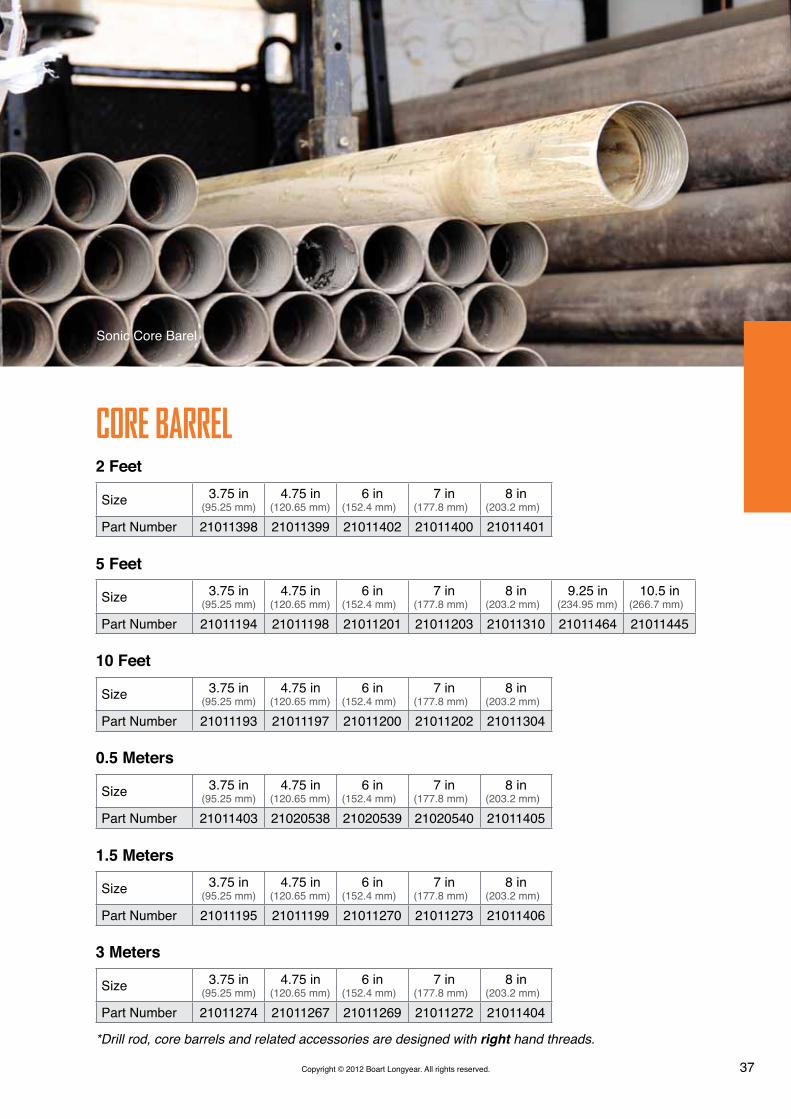
37Copyright © 2012 Boart Longyear. All rights reserved.
2 Feet
0.5 Meters
5 Feet
1.5 Meters
10 Feet
3 Meters
Size 3.75 in(95.25 mm)
4.75 in(120.65 mm)
6 in(152.4 mm)
7 in(177.8 mm)
8 in(203.2 mm)
Part Number 21011398 21011399 21011402 21011400 21011401
Size 3.75 in(95.25 mm)
4.75 in(120.65 mm)
6 in(152.4 mm)
7 in(177.8 mm)
8 in(203.2 mm)
Part Number 21011403 21020538 21020539 21020540 21011405
Size 3.75 in(95.25 mm)
4.75 in(120.65 mm)
6 in(152.4 mm)
7 in(177.8 mm)
8 in(203.2 mm)
9.25 in(234.95 mm)
10.5 in(266.7 mm)
Part Number 21011194 21011198 21011201 21011203 21011310 21011464 21011445
Size 3.75 in(95.25 mm)
4.75 in(120.65 mm)
6 in(152.4 mm)
7 in(177.8 mm)
8 in(203.2 mm)
Part Number 21011195 21011199 21011270 21011273 21011406
Size 3.75 in(95.25 mm)
4.75 in(120.65 mm)
6 in(152.4 mm)
7 in(177.8 mm)
8 in(203.2 mm)
Part Number 21011193 21011197 21011200 21011202 21011304
Size 3.75 in(95.25 mm)
4.75 in(120.65 mm)
6 in(152.4 mm)
7 in(177.8 mm)
8 in(203.2 mm)
Part Number 21011274 21011267 21011269 21011272 21011404
COrE BArrEL
Sonic Core Barel
*Drill rod, core barrels and related accessories are designed with right hand threads.

38 Copyright © 2012 Boart Longyear. All rights reserved.
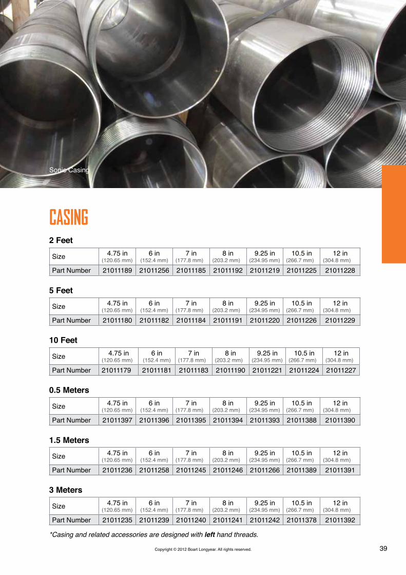
CASING
Casing Thread-ends DimensionsInner Diameter Outer Diameter
Size Metric U.S. Metric U.S.4.75 in (120.65 mm) 100.08 mm 3.94 in 122.68 mm 4.83 in6 in (152.4 mm) 127 mm 5 in 152.4 mm 6 in7 in (177.8 mm) 158.24 mm 6.23 in 179.07 mm 7.05 in8 in (203.2 mm) 184.91 mm 7.28 in 205.74 mm 8.1 in9.25 in (234.95 mm) 213.36 mm 8.4 in 234.95 mm 9.25 in10.5 in (266.7 mm) 245.11 mm 9.65 in 266.7 mm 10.5 in12 in (304.8 mm) 276.35 mm 10.88 in 304.8 mm 12 in
Inner Diameter Outer DiameterSize Metric U.S. Metric U.S.4.75 in (120.65 mm) 107.95 mm 4.25 in 120.65 mm 4.75 in6 in (152.4 mm) 139.7 mm 5.5 in 152.4 mm 6 in7 in (177.8 mm) 165.1 mm 6.5 in 177.8 mm 7 in8 in (203.2 mm) 190.5 mm 7.5 in 203.2 mm 8 in9.25 in (234.95 mm) 222.25 mm 8.75 in 234.95 mm 9.25 in10.5 in (266.7 mm) 254 mm 10 in 266.7 mm 10.5 in12 in (304.8 mm) 292.1 mm 11.5 in 304.8 mm 12 in
Casing Mid-body Dimensions
Casing SelectorCore Barrel Casing
Size 4.75 in(120.65 mm)
6 in(152.4 mm)
7 in(177.8 mm)
8 in(203.2 mm)
9.25 in(234.95 mm)
10.5 in(266.7 mm)
12 in(304.8 mm)
3.75 in(95.25 mm)
4.5 in(114.3 mm)
4.75 in(120.65 mm)
6 in(152.4 mm)
7 in(177.8 mm)
8 in(203.2 mm)
9 in(228.6 mm)
10 in(254 mm)
= Ideal combination = Optional combinations
*Casing and related accessories are designed with left hand threads.
39Copyright © 2012 Boart Longyear. All rights reserved.
2 Feet
0.5 Meters
5 Feet
1.5 Meters
10 Feet
3 Meters
Size 4.75 in(120.65 mm)
6 in(152.4 mm)
7 in(177.8 mm)
8 in(203.2 mm)
9.25 in(234.95 mm)
10.5 in(266.7 mm)
12 in(304.8 mm)
Part Number 21011189 21011256 21011185 21011192 21011219 21011225 21011228
Size 4.75 in(120.65 mm)
6 in(152.4 mm)
7 in(177.8 mm)
8 in(203.2 mm)
9.25 in(234.95 mm)
10.5 in(266.7 mm)
12 in(304.8 mm)
Part Number 21011397 21011396 21011395 21011394 21011393 21011388 21011390
Size 4.75 in(120.65 mm)
6 in (152.4 mm)
7 in(177.8 mm)
8 in(203.2 mm)
9.25 in(234.95 mm)
10.5 in(266.7 mm)
12 in(304.8 mm)
Part Number 21011180 21011182 21011184 21011191 21011220 21011226 21011229
Size 4.75 in(120.65 mm)
6 in(152.4 mm)
7 in(177.8 mm)
8 in(203.2 mm)
9.25 in(234.95 mm)
10.5 in(266.7 mm)
12 in(304.8 mm)
Part Number 21011236 21011258 21011245 21011246 21011266 21011389 21011391
Size 4.75 in(120.65 mm)
6 in(152.4 mm)
7 in(177.8 mm)
8 in(203.2 mm)
9.25 in(234.95 mm)
10.5 in(266.7 mm)
12 in(304.8 mm)
Part Number 21011179 21011181 21011183 21011190 21011221 21011224 21011227
Size 4.75 in(120.65 mm)
6 in(152.4 mm)
7 in(177.8 mm)
8 in(203.2 mm)
9.25 in(234.95 mm)
10.5 in(266.7 mm)
12 in(304.8 mm)
Part Number 21011235 21011239 21011240 21011241 21011242 21011378 21011392
CASING
Sonic Casing
*Casing and related accessories are designed with left hand threads.

40 Copyright © 2012 Boart Longyear. All rights reserved.
Cop
yrig
ht ©
201
2 Bo
art L
ongy
ear.
All r
ight
s re
serv
ed.
40 Bolt-on Sub-saver

41Copyright © 2012 Boart Longyear. All rights reserved.
42424242434445
Flange AdaptersBolt-on Sub-saverCasing Plug / Ring
Cross-over SubsAdapters
Sub-saversRetrieving Tools
ACCESSOrIES

42 Copyright © 2012 Boart Longyear. All rights reserved.
FLANGE AdAPTEr
BOLT-ON SUB-SAvEr
CASING PLUG / rING
CrOSS-OvEr SUBS
Flange AdapterConnects head flange to bolt on sub-saver
Bolt-on Sub-saverConnects head to drill pipe/casing
Casing PlugsUsed for handling casing
Casing RingsPrevents casing from falling down the hole
Cross-over SubsConnects dissimilar threaded tooling
Description Flange Extension Head BL 150Part Number 24030361
DescriptionStandard Flange Adapter
3.5 in RH x 6 in LH Bolt-on Sub-saver
Optional Flange Adapter API-Reg 2 3/8 in RH x 6 in LH
Bolt-on Sub-saverPart Number 24030362 24030387
Size 3.75 in(95.25 mm)
4.75 in(120.65 mm)
6 in(152.4 mm)
7 in(177.8 mm)
8 in(203.2 mm)
Part Number 24070042 24070043 24070044 24070045 24070046
SizeNWJ Pin x 3.5 in Box
NWJ Pin x 3.5 in Pin
AWJ Pin x 3.5 in Box
AWJ Pin x 3.5 in Pin
2 in NPT Box x 3.5
in BoxPart Number 350-2624 350-2622 350-2623 350-2625 350-2621
Size 3.5 in RH Pin x 2-3/8 in API-IF BoxPart Number 4033894
Size 4.75 in(120.65 mm)
6 in(152.4 mm)
7 in(177.8 mm)
8 in(203.2 mm)
9 in(228.6 mm)
Part Number 21190166 21190167 21190168 21190169 21190170
Size 9 in(228.6 mm)
10.5 in(266.7 mm)
12 in(304.8 mm)
Part Number 24070047 24070048 24070049
Size 10.5 in(266.7 mm)
12 in(304.8 mm)
Part Number 21190171 21190172
*Other options are available upon request
*Other options are available upon request
43Copyright © 2012 Boart Longyear. All rights reserved.
Size 3.75 in(95.25 mm)
4.75 in(120.65 mm)
6 in(152.4 mm)
7 in(177.8 mm)
8 in(203.2 mm)
Part Number 24070042 24070043 24070044 24070045 24070046
SizeNWJ Pin x 3.5 in Box
NWJ Pin x 3.5 in Pin
AWJ Pin x 3.5 in Box
AWJ Pin x 3.5 in Pin
2 in NPT Box x 3.5
in BoxPart Number 350-2624 350-2622 350-2623 350-2625 350-2621
Size 3.5 in RH Pin x 2-3/8 in API-IF BoxPart Number 4033894
Size 4.75 in(120.65 mm)
6 in(152.4 mm)
7 in(177.8 mm)
8 in(203.2 mm)
9 in(228.6 mm)
Part Number 21190166 21190167 21190168 21190169 21190170
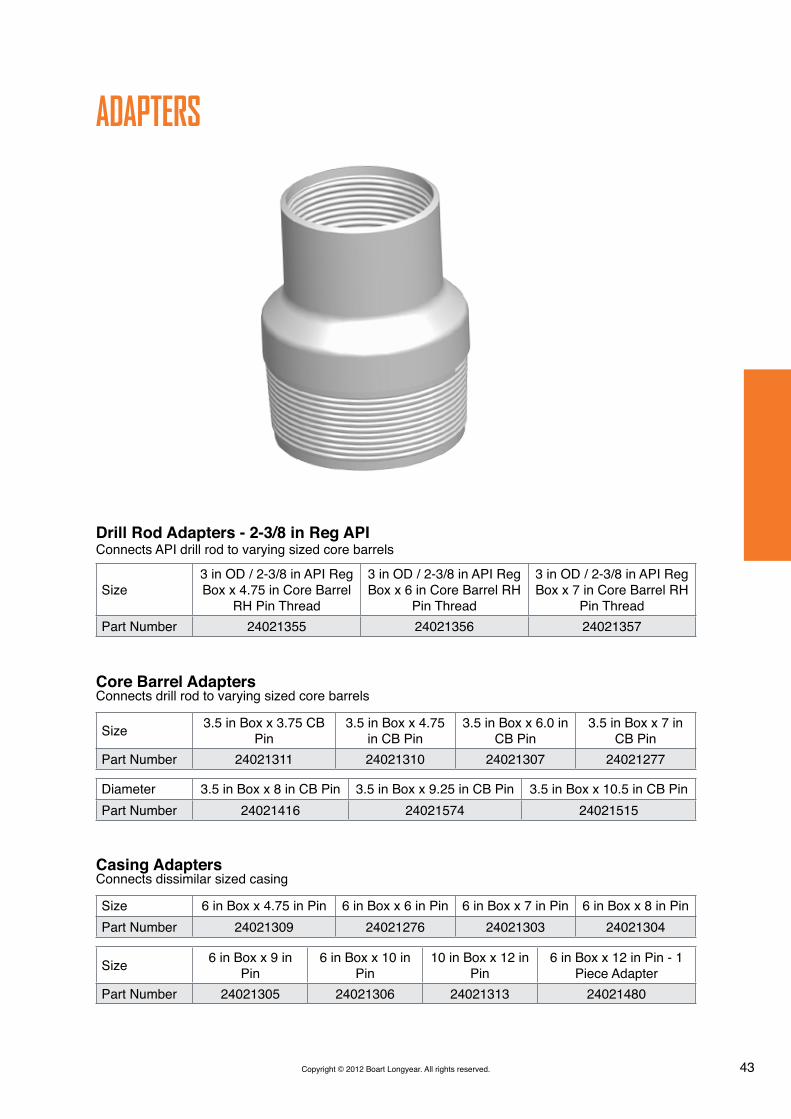
Core Barrel AdaptersConnects drill rod to varying sized core barrels
Casing AdaptersConnects dissimilar sized casing
AdAPTErS
Size 6 in Box x 4.75 in Pin 6 in Box x 6 in Pin 6 in Box x 7 in Pin 6 in Box x 8 in PinPart Number 24021309 24021276 24021303 24021304
Size 3.5 in Box x 3.75 CB Pin
3.5 in Box x 4.75 in CB Pin
3.5 in Box x 6.0 in CB Pin
3.5 in Box x 7 in CB Pin
Part Number 24021311 24021310 24021307 24021277
Size 6 in Box x 9 in Pin
6 in Box x 10 in Pin
10 in Box x 12 in Pin
6 in Box x 12 in Pin - 1 Piece Adapter
Part Number 24021305 24021306 24021313 24021480
Diameter 3.5 in Box x 8 in CB Pin 3.5 in Box x 9.25 in CB Pin 3.5 in Box x 10.5 in CB PinPart Number 24021416 24021574 24021515
Drill Rod Adapters - 2-3/8 in Reg APIConnects API drill rod to varying sized core barrels
Size3 in OD / 2-3/8 in API Reg Box x 4.75 in Core Barrel
RH Pin Thread
3 in OD / 2-3/8 in API Reg Box x 6 in Core Barrel RH
Pin Thread
3 in OD / 2-3/8 in API Reg Box x 7 in Core Barrel RH
Pin ThreadPart Number 24021355 24021356 24021357

44 Copyright © 2012 Boart Longyear. All rights reserved.
3.5 in Thread Sub-Savers (Drill Rod)Varies drill rod string length
6 in Thread Sub-Savers (Casing)Varies casing string length
SUB-SAvErS
Size 3.5 in RH Box x Pin x 9.5 in
3.5 in RH Pin x Pin x 18 in
3.5 in RH Pin x Pin x 15 in - 1 Piece Flange
Part Number 24021314 24021354 24021365
Size 3.5 in RH Box x Pin x 18 in Rod 3.5 in RH Box x Pin x 12 in (ACE)
Part Number 24021464 21020530
Size 6 in LH Box x 6 in LH Pin x 8 in
6 in LH Box x 6 in LH Pin x 18 in
6 in LH Box x 6 in LH Pin x 14 in
Part Number 24021302 21020564 21020572
Size 6 LH Box x 6 in LH Pin x 24 in S/S (Deuce)
6 in LH Box x 6 in LH Pin x 24 in S/S
Part Number 21011256 21020529
Thread Sub-saver

45Copyright © 2012 Boart Longyear. All rights reserved.
3.5 in Thread Sub-Savers (Drill Rod)Varies drill rod string length
6 in Thread Sub-Savers (Casing)Varies casing string length
rETrIEvING TOOLS
Taper Tap - CasingRetrieves broken casing
Overshot - Drill RodRetrieves broken drill rod
Taper Tap - Core BarrelRetrieves broken core barrel
Taper Tap - Drill RodRetrieves broken drill rod
Diameter 3.5 in 2-3/8 in API RegPart Number 24720186 24720202
Diameter 4.75 in(120.65 mm)
6 in(152.4 mm)
7 in(177.8 mm)
8 in(203.2 mm)
9.25 in(234.95 mm)
10.5 in(266.7 mm)
Part Number 24720183 24720175 24720176 24720181 24720182 24720180
Diameter 3.75 in(95.25 mm)
4.75 in(120.65 mm)
6 in(152.4 mm)
7 in(177.8 mm)
8 in(203.2 mm)
Part Number 24720187 24720184 24720178 24720185 24720203
Diameter 9.25 in(234.95 mm)
10.5 in(266.7 mm)
Part Number 24720219 24720220
Diameter 3.5 in(120.65 mm)
2-3/8 in API Reg(152.4 mm)
Part Number 24720179 24720177

46 Copyright © 2012 Boart Longyear. All rights reserved.
Cop
yrig
ht ©
201
2 Bo
art L
ongy
ear.
All r
ight
s re
serv
ed.
46 Lexan Core Barrel

47Copyright © 2012 Boart Longyear. All rights reserved.
48505252535354
Lexan Soil SamplersRod/Casing Handling System
Discrete Point SamplersIso-Flow Sampler
Miscellaneous ToolingConsumablesWrench Parts
MISCELLANEOUS
48
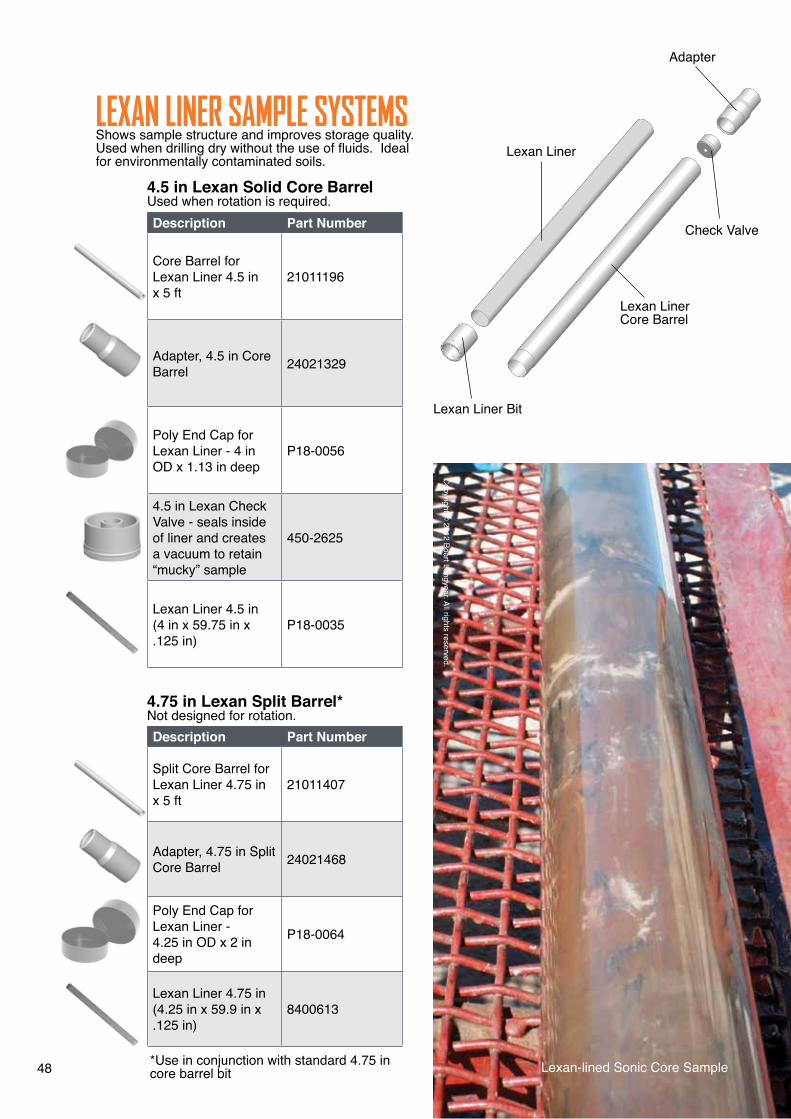
LExAN LINEr SAMPLE SYSTEMSShows sample structure and improves storage quality. Used when drilling dry without the use of fluids. Ideal for environmentally contaminated soils.
4.5 in Lexan Solid Core BarrelUsed when rotation is required.
4.75 in Lexan Split Barrel*Not designed for rotation.
Description Part Number
Core Barrel for Lexan Liner 4.5 in x 5 ft
21011196
Adapter, 4.5 in Core Barrel 24021329
Poly End Cap for Lexan Liner - 4 in OD x 1.13 in deep
P18-0056
4.5 in Lexan Check Valve - seals inside of liner and creates a vacuum to retain “mucky” sample
450-2625
Lexan Liner 4.5 in (4 in x 59.75 in x .125 in)
P18-0035
Description Part Number
Split Core Barrel for Lexan Liner 4.75 in x 5 ft
21011407
Adapter, 4.75 in Split Core Barrel 24021468
Poly End Cap for Lexan Liner - 4.25 in OD x 2 in deep
P18-0064
Lexan Liner 4.75 in (4.25 in x 59.9 in x .125 in)
8400613
Lexan-lined Sonic Core Sample
Lexan Liner
Check Valve
Adapter
Lexan Liner Bit
Lexan Liner Core Barrel
*Use in conjunction with standard 4.75 in core barrel bit
Copyright ©
2012 Boart Longyear. All rights reserved.

49Copyright © 2012 Boart Longyear. All rights reserved.
BOArT LONGYEAr APP
UP-TO-dATE INFOrMATION, INSTANTLY.Boart Longyear is pleased to announce the launch of its app, now available on the iTunes App Store. The app contains all of Boart Longyear’s brochures and catalogs as well as the latest company news, tweets and videos.
Updates to brochures and catalogs are instantly pushed to the App, enabling our clients to have the most up to date information, instantly.
To download the App now, scan the QR code below:
Available at iTunes App Store
www.BoartLongyear.com • ASX: BLY
50 Copyright © 2012 Boart Longyear. All rights reserved.
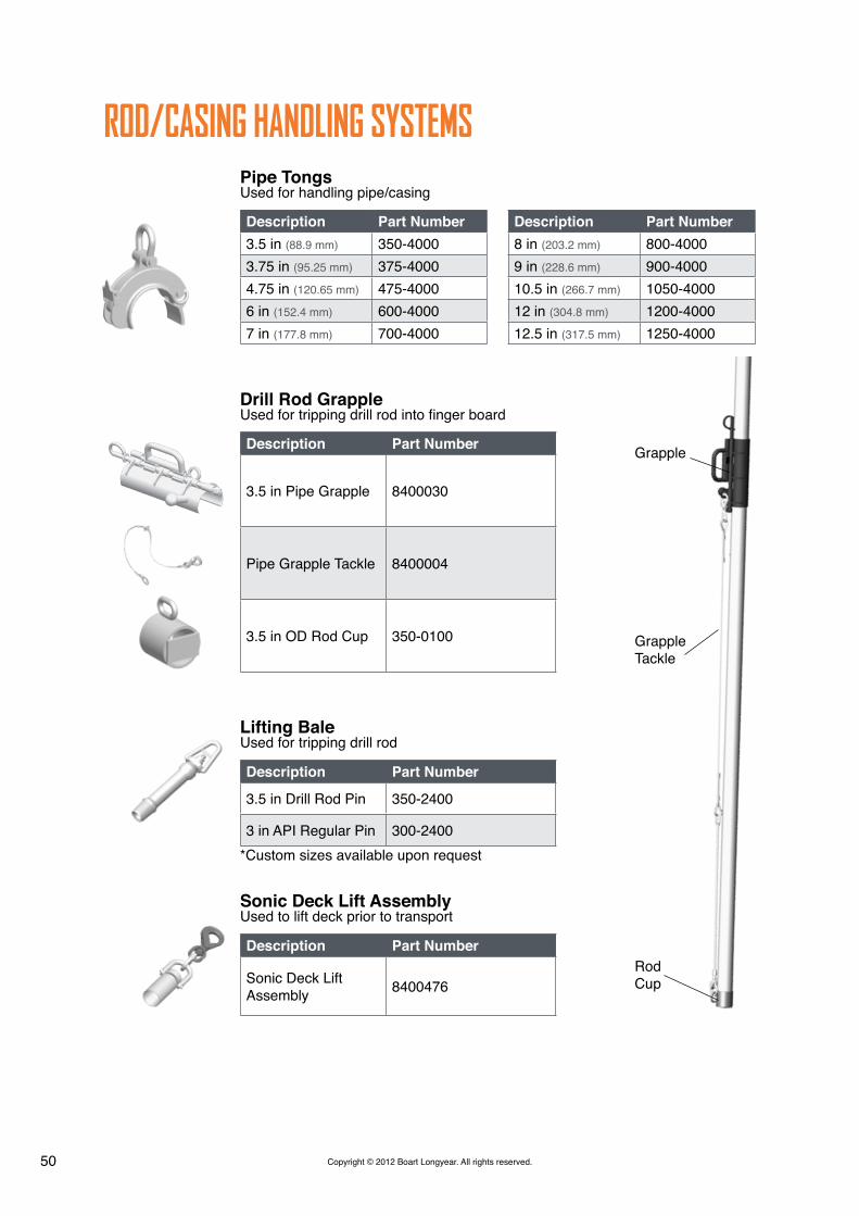
Pipe TongsUsed for handling pipe/casing
Drill Rod GrappleUsed for tripping drill rod into finger board
Lifting BaleUsed for tripping drill rod
Sonic Deck Lift AssemblyUsed to lift deck prior to transport
rOd/CASING HANdLING SYSTEMS
Description Part Number3.5 in (88.9 mm) 350-40003.75 in (95.25 mm) 375-40004.75 in (120.65 mm) 475-40006 in (152.4 mm) 600-40007 in (177.8 mm) 700-4000
Description Part Number8 in (203.2 mm) 800-40009 in (228.6 mm) 900-400010.5 in (266.7 mm) 1050-400012 in (304.8 mm) 1200-400012.5 in (317.5 mm) 1250-4000
Description Part Number
3.5 in Pipe Grapple 8400030
Pipe Grapple Tackle 8400004
3.5 in OD Rod Cup 350-0100
Description Part Number
3.5 in Drill Rod Pin 350-2400
3 in API Regular Pin 300-2400
Description Part Number
Sonic Deck Lift Assembly 8400476
Grapple
GrappleTackle
Rod Cup
*Custom sizes available upon request

51Copyright © 2012 Boart Longyear. All rights reserved. Rod/Casing Handling System 51

52 Copyright © 2012 Boart Longyear. All rights reserved.Copyright © 2012 Boart Longyear. All rights reserved.
dISCrETE POINT SAMPLErSUsed with drill rod for down hole water sampling
ISO-FLOW SAMPLEr rEEL ASSEMBLYUsed for open-hole water sampling
Description 3.5 in Discrete Point Water Sampler Water Sample on Point Pin Opening Size 1/15 in 16 Ports
Part Number 8400385
Description Complete Iso-Flow Reel AssemblyPart Number 5200-00
DescriptionDiscrete Water Sampler Point Discrete Water Sampler Rod Body
Water Sample on Rod Pin Opening Size: .375 in 4 Ports
Part Number 350-3010 350-3020
Description 3.5 in Discrete Water Sampler O-Ring Water Sample Laser Cut Screen Slot Size: 1 in x .020 in 324 Slots
Part Number 8400715
Monitoring Well

53Copyright © 2012 Boart Longyear. All rights reserved.
MISCELLANEOUS TOOLINGDescription Part Number
Core Sample Tray P19-0151
3.5 in Thread Protector 350-3001
Poly Core Bags
Visqueen
Pipe Dope
CONSUMABLES
Core Size 4.75 in 6 in 7 in 8 in
Description 1,000 ft (304.8 m) Core bag roll
1,000 ft (304.8 m) Core bag roll
1,000 ft (304.8 m) Core bag roll
1,000 ft (304.8 m) Core bag roll
Part Number 475-5000 600-5000 700-5000 800-5000
Description 6 mil. x 20 in x 100 ft rollPart Number 8400429
Description Well Guard Pipe Dope - 1 Gallon Bucket (36 / Pallet)Part Number 8400308
Poly Core Bag

54 Copyright © 2012 Boart Longyear. All rights reserved.
Jaw Blocks
Jaw Teeth
Jaw Block Keeper
Jaw Block Bolts
WrENCH PArTS
Description Part Number
Keeper Bolts (Small Diameter Casing) (3/8 in - 16 x 1”) P08-0124
Keeper Bolts (Large Diameter Casing) (5/16 in - 18 x 1”) P08-0129
Jaw Blocks Bolts (3/4 in - 10 x 3-1/4 in) P08-0128
Description Part Number
Small Diameter Jaw Blocks (Smaller than 10 in Diameter
20183-00
Larger Diameter Jaw Blocks (Greater than 10 in Diameter)
20184-00
Delta Base Jaw Block 8400625
Jaw Block Keeper and Bolt
Jaw Teeth
Jaw Block
Description Part Number
Jaw Teeth 20185-04
Description Part Number
Keeper, Jaw Block (Smaller than 10 in Diameter) 20185-06
Keeper, Jaw Blocks (Greater than 10 in Diameter) - requires 2 per jaw block
20185-07

55Copyright © 2012 Boart Longyear. All rights reserved.
Jaw Blocks
Jaw Teeth
Jaw Block Keeper
Jaw Block Bolts
55Foot Clamp on LS™600 Sonic Drill

56 Copyright © 2012 Boart Longyear. All rights reserved.
Cop
yrig
ht ©
201
2 Bo
art L
ongy
ear.
All r
ight
s re
serv
ed.
56 LS™600 Sonic Rig

57Copyright © 2012 Boart Longyear. All rights reserved.
5858585960
StabbingNew Rod Make-up
Pre-loadingThread Introduction
Break-out / Fluid Seal
APPLICATION

58 Copyright © 2012 Boart Longyear. All rights reserved.
Drill rods and casing provide very little radial clearance when first inserting a pin end into a box end (stabbing). If the pin end is not aligned, it will stab into the box end shoulder causing permanent damage regardless of design or heat treatment. This damage will create leakage ranging from negligible to significant, depending on the degree of damage. Severe stabs can compromise the fit of the joint and potentially cause fatigue failures. Once the face of the pin end shoulder
Rods and casing make-up slowly by rotating the pin into the box (clockwise for rod and core barrels, counterclockwise for casing). If the stand-off gap is outside specification or if the joint does not close after applying a small amount of make-up torque, break-out the joint, clean and inspect both threads. This is an indication of excessive wear, excessive foreign material or thread deformation due to overloading during making or breaking. It may also indicate that the product is from a different manufacturer.
After the stand-off gap is closed, additional make-up is required to sufficiently pre-load the joint. Make-up can be applied with the drill head or other power make-up devices. This is to ensure the box shoulder does not become unloaded during drilling allowing leakage, fretting or premature fatigue failures. Joints will not self make-up sufficiently during drilling alone as the joint has additional frictional resistance to make-up under drilling loads. Another visual sign of insufficient make-up is
STABBING
MAKE-UP
MAKE-UP TOrQUE (PrE-LOAdING)
is even with the face of the box end shoulder, the pin end should be lowered slowly into the box until the face of the pin thread mates against the face of the box thread. If the pin is not in true vertical alignment over the box or if the joint has insufficient taper to allow the first turn of pin thread to clear the first turn of box thread, the pin thread crest may wedge or “jam” against the box thread crest or begin to cross thread. Rotating the connection counter-clockwise 1/4 to 1/2 turn will correct the misalignment. Once successfully lowered, rotate the stabbing rod to ensure proper thread engagement (see make-up).
pitting-wear in the joints due to fretting and fatigue failures.
The pin end of a drill rod is engineered to be slightly shorter than the box end to allow pre-loading of the box shoulder and elastic response to drilling loads. This is evident by a gap at the internal torque shoulder. Under extraordinary make-up or drilling torque, the pin and box will be sufficiently loaded to close this gap and engage the internal torque shoulder providing additional torque capacity.

59Copyright © 2012 Boart Longyear. All rights reserved.
THrEAd INTrOdUCTION (FOr NEW drILL rOd/CASING)
THrEAd INTrOdUCTION PrOCEdUrEStep 1Apply ample amount of thread compound to the pin end of the new thread.
Step 2Using the drill head, thread the new pin end into the new box end of the mating pipe. (keep rotation pressure below 1,000 PSI)
Step 3Thread and un-thread the pipe 4 to 5 times.
Step 4Remove excess grease from both the pin end and box end of the pipe. This will remove any burrs or imperfections that may have been removed during the introduction process.
Introducing new threads is necessary to help prevent problems that may occur when making or breaking pipe during drilling. Introducing newly machined threads to each other multiple times removes any imperfections from them.

60 Copyright © 2012 Boart Longyear. All rights reserved.
BrEAK-OUTTheory and laboratory tests show break-out torque should be 70 - 80% of the make-up or drilling torque applied to each joint. Despite this, breaking-out may be problematic due to adhesion wear or the fact that some drill rigs do not have the same load capacity in breaking as they do in making-up or drilling. Additionally, during drilling the joints are subject to vibration and loss of thread compound reducing the frictional resistance and allowing incremental make-up. Note that a poor choice of compound will contribute to this effect as well. This may result in a break-out torque requirement that exceeds the original make-up applied. This can be overcome utilizing the same effect by applying a slight percussive blow to the side of the box with a rubber mallet or similar non-damaging tool. Do not use a metal hammer or similarly hard objects. They will affect material properties in the impacted area and potentially cause fatigue failures and may void the Boart Longyear warranty. Once the threads have disengaged, the pin can be slowly unthreaded. Cleaning and re-lubricating is recommended to maximize wear life.
FLUId SEALDrill rods and casing utilize steel-on-steel interfaces as a fluid seal. Make-up torque is required to load the box end’s shoulder face against the pin’s external shoulder face to develop the necessary contact pressure at the interface. Given the high elastic modulus of steel, the performance of these seals is very limited despite seal face geometry or heat treatment. As a result, the fluid seal is very sensitive to damage on either seal face.
Note: Applying wrenches to external shoulder will cause leakage (see stabbing)
60 Copyright © 2012 Boart Longyear. All rights reserved.

61Copyright © 2012 Boart Longyear. All rights reserved. 61Foot Clamp on LS™600 Sonic Drill

62 Copyright © 2012 Boart Longyear. All rights reserved.
Cop
yrig
ht ©
201
2 Bo
art L
ongy
ear.
All r
ight
s re
serv
ed.

63Copyright © 2012 Boart Longyear. All rights reserved.
646465666667
Lubrication and CleaningTransit and Storage
Thread WearBox and Mid-body Wear
Loads and Deviated HolesSerialization/Lot Code
WEAr ANd CArE
64 Copyright © 2012 Boart Longyear. All rights reserved.
Boart Longyear™ drill rod threads are created with thread compound (lubricant) for shipment from the factory. For initial use, it is neither necessary nor desirable to remove the thread compound unless contamination has occurred. Thereafter, each time the rods are used, clean and re-lubricate the threads with Boart Longyear recommended compound. Use enough compound to cover both thread and shoulder surfaces. A 40 to 50 mm (1.5 in to 2 in) brush is excellent for applying compound.
Note: • Keep the compound and brush clean• While occasional mixing of the compound
is recommended to avoid settling, dilution of any kind (e.g. Diesel, gasoline or oil) will render the compound ineffective.
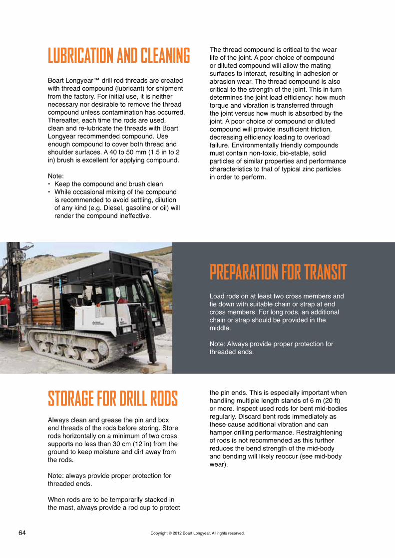
Load rods on at least two cross members and tie down with suitable chain or strap at end cross members. For long rods, an additional chain or strap should be provided in the middle.
Note: Always provide proper protection for threaded ends.
Always clean and grease the pin and box end threads of the rods before storing. Store rods horizontally on a minimum of two cross supports no less than 30 cm (12 in) from the ground to keep moisture and dirt away from the rods.
Note: always provide proper protection for threaded ends.
When rods are to be temporarily stacked in the mast, always provide a rod cup to protect
LUBrICATION ANd CLEANING
PrEPArATION FOr TrANSIT
STOrAGE FOr drILL rOdS
The thread compound is critical to the wear life of the joint. A poor choice of compound or diluted compound will allow the mating surfaces to interact, resulting in adhesion or abrasion wear. The thread compound is also critical to the strength of the joint. This in turn determines the joint load efficiency: how much torque and vibration is transferred through the joint versus how much is absorbed by the joint. A poor choice of compound or diluted compound will provide insufficient friction, decreasing efficiency loading to overload failure. Environmentally friendly compounds must contain non-toxic, bio-stable, solid particles of similar properties and performance characteristics to that of typical zinc particles in order to perform.
the pin ends. This is especially important when handling multiple length stands of 6 m (20 ft) or more. Inspect used rods for bent mid-bodies regularly. Discard bent rods immediately as these cause additional vibration and can hamper drilling performance. Restraightening of rods is not recommended as this further reduces the bend strength of the mid-body and bending will likely reoccur (see mid-body wear).

65Copyright © 2012 Boart Longyear. All rights reserved.
The wear of sliding steel-on-steel surfaces, such as in a rod or casing joint, is well defined in engineering literature. Galling is the common industry term given to thread wear which mainly consists of adhesion and abrasion wear as a result of making and breaking. While some wear can be tolerated without compromising performance, worn surfaces are prone to further wear. Unattended, the degree of wear can worsen to the point where it can cause premature failure or in case of mating surfaces of similar hardness, seize the joint. Alternatively, a worn thread can damage a good thread.
The rate of wear to be expected in a sliding metal-to-metal system can only be determined by considering all the following variables:• Lubrication or wear factor: published values
are greater for poor lubrication; less for mating surfaces of dissimilar hardness (see lubrication and cleaning)
• The hardness of the softer surface• The distance of contact slide• The contact load or pressure
Less Wear can be achieved by:• Cleaning and lubricating joints regularly;
preferably after every break. Dry lubrication coatings are available but these wear off and must also be cleaned and lubricated (See lubrication and cleaning)
THrEAd WEAr • Choosing joints with mating surfaces of dissimilar hardness. Published data shows that given equal contact pressures and equal hardness on the softer surfaces, a system with a harder mating surface (dissimilar hardness) can provide several times the wear life
• Choosing joints with greater hardness on the softer thread
• Reduce the sliding contact distance by choosing joints with greater taper
• Reduce or eliminate the contact pressure by adjusting the feed rate and rotation speed during make and break to match the thread pitch and compensate for rod and drill head weight.
Another source of rod joint wear is worn accessories. All threaded accessory equipment, such as drivers, adapter subs, hoist plugs, and cross-over adapter subs should be inspected prior to use to ensure they are in good condition. Use only genuine Boart Longyear accessories to ensure proper fits and maximum wear life. Boart Longyear tooling and gauging adhere to an uncompromising global standard.

66 Copyright © 2012 Boart Longyear. All rights reserved.
BOx ANd MIdBOdY WEArSimilar to the steel-on-steel wear systems of the joint, the box and mid-body are subject to relative sliding contact with the wall of the casing or hole. In the case of wear against the wall of the hole, the surface of the hole may be of significantly greater hardness and roughness (not to mention cuttings suspended in the drilling fluid) potentially resulting in rapid wear rates. However, in many applications other causes of drill rod/casing retirement is due to localized wear resulting from the deformation of the box being out of a flush position or of the typical mid-body being out of straight.
In typical joints, it is inherent for the box and box end shoulder to elastically deform radially or ‘bulge’. This is due to radial and hoop stresses imposed by conventional threads which add to drilling load stresses. This is evident by a polished area on the side of the joint where thread engagement begins or a thin section in the box shoulder.
As the wear progresses, the box becomes weaker and the deformation more pronounced, increasing the wear rate. It is inherent for a rod string to respond to significant drilling loads and rotation in a three dimensional corkscrew shape, a phenomenon first identified and defined by Boart Longyear as ‘helical whirling’. As loads or rotation increase, the contact pressure between the string and the hole increases contributing to an increased mid-body wear rate.
Given sufficient contact pressure and speed, the heat generated between the rod or casing string and casing or hole can cause heat-check cracking which ultimately appears as an axial crack, typically on the box end. The bending stresses associated with this helical whirling become significant under high load or rotation, especially in oversize holes or ‘caves’, and may cause permanent bending of the string.
LOAdS ANd dEvIATEd HOLESFatigue failures are brittle failures or cracks that occur under stress or load levels that are significantly below static load ratings; however, the loads are applied or cycled a large number of times. This phenomenon is common in rotary Sonic drilling, but is enhanced when a rod string is rotating in a deviated hole, the surface of the rod undergoes both tension and compression in each revolution in addition to the vibration. Due to the reduced cross-sections of material in the threaded ends, the joints between mated rods in the string are significantly weaker than the rod mid-bodies - regardless of heat treatment or deviation capacity of the joint.
A further limitation on the ability of a drill rod joint to perform through a bend is due to a peculiarity of the steel material itself. If there is a constant tension load applied in addition to a cyclical load, the fatigue strength is even further reduced. In the case of drill rod joints, if the joint is properly made up the pin end will always be under a greater tension load than the box end (see make-up torque). As a result, the pin end is the weakest part of a drill rod and is the typical location of failure under an excessive cyclic load. A fatigue failure crack always occurs perpendicular to the cyclic load or stress. Therefore the most common failure is a circumferentially oriented crack which indicates that the cyclic load or stress was axially oriented which can only be caused by bending. If the crack is axially oriented it is either the result of heat-check cracking or indicates that the cyclic load was circumferentially oriented and this can only be caused by improper fit of a joint in terms of make-up, deformation, foreign debris, or wear. Fatigue failures can be avoided by limiting the level of cyclic loads with consideration for the down pressure.

67Copyright © 2012 Boart Longyear. All rights reserved.
Lot Code Style #1This lot code style is most prevalent in tooling made before January 2009.
G - Refers to the manufacturing facility designation given by engineering (G=BLY Eiterfeld)
07.08 - Manufactured the 7th Mon of 2008
Lot Code Style #2This lot code style is most prevalent in tooling made after January 2009 by Boart Longyear - Germany.
The Boart Longyear logo is the designation for Boart Longyear - Germany Manufacturing Facility
24021311 - Part Number
09 - Refers to the month of manufacture;
09 - Year of manufacture; 2009
SErIALIZATION / LOT COdING
All Boart Longyear sonic tooling currently being manufactured will have the manufacturer’s lot code pin stamped or engraved into the pin end of the piece. Items that do not have a bit joint will have the lot code pin stamped or engraved into the top shoulder of one of the box ends.
It is important to find this information when reporting potential quality or safety issues to Boart Longyear.

68 Copyright © 2012 Boart Longyear. All rights reserved.
CONTACT INFOrMATIONGlobal Headquarters 10808 South River Front ParkwaySuite 600South Jordan, Utah 84095United States of [email protected]
Tel: +1 801 972 6430Fax: +1 801 977 3374
Latin America Portal RiescoAv. El Salto 4001, HuechurabaSantiago, Chile 858 [email protected]
Tel: +56 2 595 3300Fax: +51 242 671
Canada 2442 South Sheridan WayMississauga, OntarioCanada L5J [email protected]
Tel: +1 905 822 7922 Fax: +1 905 822 7232
Asia Pacific 26 Butler BoulevardAdelaide, [email protected]
Tel: +61 8 8375 8375Fax: +61 8 8375 8497
Europe 12 Avenue des MorginesCH1213 Petit-Lancy, [email protected]
Tel: +41 22 709 0800Fax: +41 22 709 0801
Sub-Saharan Africa Cycad House, Constantia Office ParkCnr 14th Avenue and Hendrik Potgieter Weltevreden Park, 1709Gauteng, South [email protected]
Tel: +27 11 767 9300Fax: +27 11 767 9301

www.BoartLongyear.com • ASX: BLYAugust 2012 Edition