drilling, coring, sampling and logging at hazardous substance
TRANSCRIPT
Drilling, Coring, Sampling and Logging at Hazardous Substance Release Sites
Guidance Manual for Ground Water Investigations
1
c
State of California Environmental Protection Agency

DRILLING, CORING, SAMPLING AND LOGGING AT HAZARDOUS SUBSTANCE RELEASE SITES
Guidance Manual for Ground Water Investigations
July 1995
Pete Wilson Governor State of California
James Strock Secretary California Environmental Protection Agency
The California Environmental Protection Agency:
Department of Toxic Substances Control State Water Resources Control Board Integrated Waste Management Board Air Resources Board Department of Pesticide Regulation Office of Environmental Health Hazard Assessment

FOREWORD
the state's environment. Within Cal/EPA, the Department of Toxic Substances Control (DTSC) has the responsibility of managing the state's hazardous waste program to protect public health and the environment. The State Water Resources Control Board and the nine Regional Water Quality Control Boards (RWQCBs), also part of Cal/EPA, have the responsibility for coordination and control of water quality, including the protection of the beneficial uses of the waters of the state. Therefore, the RWQCBs work closely with DTSC in protecting the environment.
To aid in characterizing and remediating hazardous substance release sites, DTSC had established a technical guidance work group to oversee the development of guidance documents and recommended procedures for use by its staff, local governmental agencies, responsible parties and their contractors. The Geological Support Unit (GSU) within DTSC provides geologic assistance, training and guidance. This document was prepared by GSU staff in cooperation with the technical guidance work group and the RWQCBs. This document has been prepared to provide guidelines for the investigation, monitoring and remediation of hazardous substance release sites. It should be used in conjunction with the two-volume companion reference for hydrogeologic characterization activities:
Guidelines for Hydrogeologic Characterization of Hazardous Substances Release Sites Volume 1: Field Investigation Manual Volume 2: Project Management Manual
Please note that, within the document, the more commonly used terms, hazardous waste site and toxic waste site, are used synonymously with the term hazardous substance release site. However, it should be noted that any unauthorized release of a substance, hazardous or not, that degrades or threatens to degrade water quality may require corrective action to protect its beneficial use.
This document supersedes the 1990 draft of the DTSC Scientific and Technical Standards for Hazardous Waste Sites, Volume 1, Chapter 6, and is one in a series of Cal/EPA guidance documents pertaining to the remediation of hazardous substance release sites.
The California Environmental Protection Agency (Cal/EPA) is charged with the responsibility of protecting

ACKNOWLEDGEMENTS
The preparation of this guidance document was achieved through the efforts of many individuals. The following people had primary responsibility for editing and writing:
Steve Belluomini Bill Owen John Woodling
Supervising Hazardous Substances Engineering Geologist I, Hazardous Substances Engineering Geologist, Senior Hazardous Substances Engineering Geologist.
Members of the technical guidance work group participated in the development of this document by providing comments and direction. Additional review and comments were provided by the Regional Water Quality Control Boards and Dennis Parfitt of the State Water Resources Control Board. We thank them for their cooperation and helpful suggestions.
Finally, thanks are extended to the staff of the Geological Support Unit and to the many anonymous reviewers outside DTSC, whose comments were indispensable for completing this document.
ii

TABLE OF CONTENTS
SECTION PAGE
FOREWORD ACKNOWLEDGEMENTS
1 INTRODUCTION
1.1 Purpose . . . . . . . . . . . . . . . . . . . . . . . . . . . . . . . . . . . . . . . . . . . .1.2 Application . . . . . . . . . . . . . . . . . . . . . . . . . . . . . . . . . . . . . . . . . .1.3 Limitations . . . . . . . . . . . . . . . . . . . . . . . . . . . . . . . . . . . . . . . . . . .
112
2 SUBSURFACE BORING PROGRAM . . . . . . . . . . . . . . . . . . . . . . . . . . . . . 2 3 LABORATORY ANALYSES OF SOIL. UNCONSOLIDATED
MATERIAL AND ROCK SAMPLES . . . . . . . . . . . . . . . . . . . . . . . . . . . . . . 10 4 BOREHOLE DRILLING METHODS . . . . . . . . . . . . . . . . . . . . . . . . . . . . . . . 12
4.1 Hollow-Stem Augers . . . . . . . . . . . . . . . . . . . . . . . . . . . . . . . . . . . 134.2 Solid-Stem Augers . . . . . . . . . . . . . . . . . . . . . . . . . . . . . . . . . . . . 17 4.3 Percussion Methods . . . . . . . . . . . . . . . . . . . . . . . . . . . . . . . . . . . . 18 4.4 Air Rotary. . . . . . . . . . . . . . . . . . . . . . . . . . . . . . . . . . . . . . . . . . . .. 18 4.5 Mud Rotary And Water Rotary . . . . . . . . . . . . . . . . . . . . . . . . . . . . . . 20 4.6 Dual-Wall Reverse-Circulation . . . . . . . . . . . . . . . . . . . . . . . . . . . . . . 21
5 6 STRATIGRAPHICCONTROL . . . . . . . . . . . . . . . . . . . . . . . . . . . . . . . . . 23
DECONTAMINATION OF DRILLING EQUIPMENT . . . . . . . . . . . . . . . . . . . . . 22
7 REFERENCES . . . . . . . . . . . . . . . . . . . . . . . . . . . . . . . . . . . . . . . . . . . 25
INDEX . . . . . . . . . . . . . . . . . . . . . . . . . . . . . . . . . . . . . . . . . . . . . . . . . . . . . . . .
iii
27

TABLE OF CONTENTS (CONTINUED)
ILLUSTRATIONS
Table Factors Influencing the Density of Boreholes. . . . . . . . . . . . . . . . . . . . . . . . . .
Table 2. Field Boring Log Information . . . . . . . . . . . . . . . . . . . . . . . . . . . . . . . . . . .
Table 3. Suggested Laboratory Methods for Sediment and Rock Samples . . . . . . . . . . . . . . . . . . . . . . . . . . . . . . . . . . . . . . .
Table 4. Applications and Limitations of Well Drilling Methods . . . . . . . . . . . . . . . . . . .
Table 5. Mud and Solids Control Recommendations for Lithologic Logging . . . . . . . . . . . . . . . . . . . . . . . . . . . . . . . . . . . . .
Figure 1. Possible Borehole Configurations for a Small Surface Impoundment . . . . . . . . . . . . . . . . . . . . . . . . . . . . . . . . . . .
Figure 2. Iteration of Borehole Program at a Small Surface Impoundment . . . . . . . . . . . . . . . . . . . . . . . . . . . . .
PAGE
3
9
11
14
22
6
8
iv

Drilling, Coring, Sampling and Logging
1 INTRODUCTION
The guidelines that follow are modified from the 1991 revision of Test Methods for Evaluating
Solid Waste, Volume 11, Chapter 11, published by the United States Environmental Protection Agency (USEPA). This document is commonly referenced by its document number, SW-846. The California Environmental Protection Agency (Cal/EPA) has incorporated appropriate sections of SW-846 into this document, in an effort to minimize redundant or contradictory guidance between the California Environmental Protection Agency (Cal/EPA) and USEPA.
Although developed for monitoring and corrective actions at permitted facilities under the Resource Conservation and Recovery Act (RCRA), the methods and materials discussed in Chapter 11 of SW-846 are applicable to all hazardous waste sites. As such, SW-846 is readily adaptable for investigations pursued under the authority of the Cal/EPA.
1.1 Purpose
This document is intended to provide guidelines for the sampling and description of soil and rock from boreholes drilled for the characterization of hazardous waste sites. The purpose of this document is to aid in the selection of drilling methods and sampling equipment, provide recommended quality assurance and quality control (QA/QC) procedures, and give a standardized approach to the description of samples and presentation of the resulting data. The recommendations contained herein represent, minimal criteria judged necessary to obtain quality data and assure reasonable and independently verifiable interpretations.
As of this writing, the American Society for Testing and Materials (ASTM) is also developing guidelines for drilling methods and sample description. We recognize that guidance developed by a general consensus (such as the ASTM balloting process) is often preferred by the regulated community. It is the intent of the California Environmental Protection Agency (Cal/EPA) to incorporate these and other guidelines, where technically and legally relevant, into the Cal/EPA guidance framework. The Cal/EPA is striving to keep up to date with the development of external guidelines, and every attempt has been made to incorporate the intent of those documents into the Cal/EPA guidelines. As new techniques gain acceptance and existing techniques are refined, this document will be updated accordingly to meet the state of the science.
The recommendations presented here are a subset of the larger site characterization process. The additional investigative tools necessary to adequately characterize a site are outlined in the Guidelines for Hydrogeologic Characterization of Hazardous Substa nce Release S ites (Cal/EPA, 1995).
1.2 Application
Drilling and sampling provide a means to directly observe subsurface stratigraphy. With this information, geology and hydrogeology can be characterized, contamination can be defined, and appropriate remedies can be designed to mitigate deleterious effects of a hazardous substance release. The following guidelines are presented in an effort to promote the efficient and proper use of drilling methods and sampling devices to increase the overall quality of site characterizations throughout the state.
1

Drilling, Coring, Sampling and Logging
1.3 Limitations
2
The recommendations presented here represent minimal criteria that can aid obtaining quality data and assuring reasonable and independently verifiable interpretations. Some sites may require investigative efforts above and beyond the scope of this document, while at other sites a less rigorous application of this guidance may be appropriate. It is the obligation of the responsible parties and the qualified professionals performing site investigations to consult with pertinent regulatory agencies, identify all requirements and meet them appropriately.
This document discusses broad categories of methods and devices that can be used in drilling and sampling investigations. It does not define specific operating procedures for drilling and sampling. Nor does this document propose guidelines for every available drilling method or sampling device. The qualified professional in charge of the field investigation should specify the methods, equipment and operating procedures in an appropriate work plan and document any significant departures from the work plan that were necessary during the course of the investigation.
This document does not supersede existing statutes and regulations. Federal, state and local regulations, statutes, and ordinances should be identified when required by law, and site characterization activities should be performed in accordance with the most stringent of these requirements where applicable, relevant and appropriate.
SUBSURFACE BORING PROGRAM
All hydrogeological site investigations should include a subsurface boring program. Information obtained from boreholes is necessary to characterize the subsurface at a site and to identify potential contaminant migration pathways. In some instances, preliminary site investigation techniques (e.g., soil gas, surface geophysics and cone penetrometer testing) can b e employed to optimize subsequent boring programs. A subsurface boring program should be designed as follows:
The initial number of borings and their spacing should be based on information obtained during the preliminary investigation and the spatial orientation of contaminant sources. Initial boreholes should be drilled to provide sufficientinformation to determine the scope of a more detailed evaluation of geology and to identify potential contaminant migration pathways. Boreholes should be spaced closely enough so that accurate cross-section(s) can be constructed. Factors that influence the initial number of borings are listed in Table 1.
Additional borings should be installed as needed to provide more information about the site and to refine the conceptual model. The number and placement of additional borings should be based on a preliminary conceptual model that has been refined with data obtained from initial borings and other site investigatory techniques (e.g., geophysical investigations).
2

Drilling, Coring, Sampling and Logging
Factors That May Substantiate Reduced Density of Boreholes
’Simple” geology (e.g., horizontal, thick, homogeneous geologic strata that are continuous across site and are unfractured) substantiated by site-specific geologic information
Use of electric cone penetrometer surveys with additional tools, i.e., d.c. resistivity, sampling
Use of surface geophysical methods to correlate hydrogeologic data between bore- holes. Suggested met hods: d.c. resistivity, seismic refraction and reflection, electro- magnetic induction, and ground penetrating radar
Use of surface to borehole and cross borehole geophysical methods to interpret complex subsurface geological structure. Suggested methods: d.c. resistivity, seismic refraction and reflection, electromagnetic induction, and ground penetrating radar
Factors That May Substantiate Increased Density of Boreholes
Fracture zones, conduits in karst terranes
Suspected pinchout zones (i.e., discontinuous strata across the site)
Tilted or folded geologic formations
@ Suspected zones of high hydraulic conductivity that would not be defined by drilling at large horizontal intervals
Laterally transitional geologic units with irregular hydraulic conductivity (e.g., sedimentary facies changes)
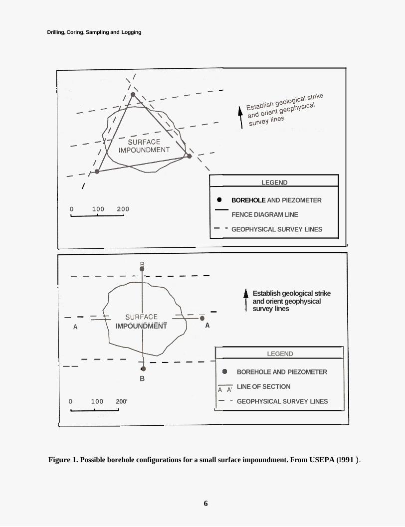
Table 1. Factors influencing the density of boreholes. From USEPA (1991).
Drilling, Coring, Sampling and Logging
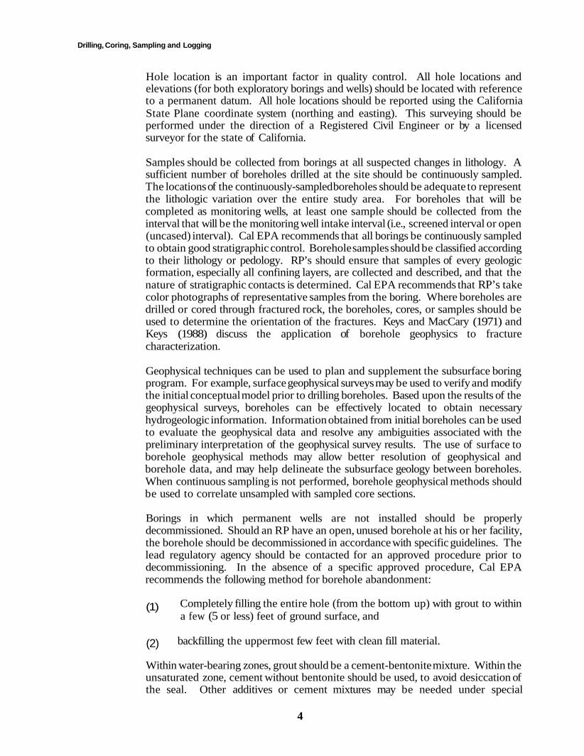
Hole location is an important factor in quality control. All hole locations and elevations (for both exploratory borings and wells) should be located with reference to a permanent datum. All hole locations should be reported using the California State Plane coordinate system (northing and easting). This surveying should be performed under the direction of a Registered Civil Engineer or by a licensed surveyor for the state of California.
Samples should be collected from borings at all suspected changes in lithology. A sufficient number of boreholes drilled at the site should be continuously sampled. The locations of the continuously-sampled boreholes should be adequate to represent the lithologic variation over the entire study area. For boreholes that will be completed as monitoring wells, at least one sample should be collected from the interval that will be the monitoring well intake interval (i.e., screened interval or open (uncased) interval). Cal EPA recommends that all borings be continuously sampled to obtain good stratigraphic control. Borehole samples should be classified according to their lithology or pedology. RP’s should ensure that samples of every geologic formation, especially all confining layers, are collected and described, and that the nature of stratigraphic contacts is determined. Cal EPA recommends that RP’s take color photographs of representative samples from the boring. Where boreholes are drilled or cored through fractured rock, the boreholes, cores, or samples should be used to determine the orientation of the fractures. Keys and MacCary (1971) and Keys (1988) discuss the application of borehole geophysics to fracture characterization.
Geophysical techniques can be used to plan and supplement the subsurface boring
program. For example, surface geophysical surveys may be used to verify and modify the initial conceptual model prior to drilling boreholes. Based upon the results of the geophysical surveys, boreholes can be effectively located to obtain necessary hydrogeologic information. Information obtained from initial boreholes can be used to evaluate the geophysical data and resolve any ambiguities associated with the preliminary interpretation of the geophysical survey results. The use of surface to borehole geophysical methods may allow better resolution of geophysical and borehole data, and may help delineate the subsurface geology between boreholes. When continuous sampling is not performed, borehole geophysical methods should be used to correlate unsampled with sampled core sections.Borings in which permanent wells are not installed should be properly decommissioned. Should an RP have an open, unused borehole at his or her facility, the borehole should be decommissioned in accordance with specific guidelines. The lead regulatory agency should be contacted for an approved procedure prior to decommissioning. In the absence of a specific approved procedure, Cal EPA recommends the following method for borehole abandonment:
(1) Completely filling the entire hole (from the bottom up) with grout to within a few (5 or less) feet of ground surface, and
(2) backfilling the uppermost few feet with clean fill material.
Within water-bearing zones, grout should be a cement-bentonite mixture. Within the unsaturated zone, cement without bentonite should be used, to avoid desiccation of the seal. Other additives or cement mixtures may be needed under special
4

Drilling, Coring, Sampling and Logging
circumstances. ASTM (1992) may be consulted for more information on grout mixtures. To prevent bridging and help ensure a good seal, grout should be kept under pressure during emplacement. This can be achieved by use of a tremie pipe to feed grout into the hole. At all times, the opening of the tremie pipe should be submerged several (2 or more) feet below the level of grout in the hole. The amount of submergence will be dependent on the amount of pressure needed to assure adequate penetration of grout into the formation. Free-fall emplacement of grout is not considered an acceptable practice.
In some situations, it may be necessary to drill through actual or possible confining layers at a site. Special precautions should be taken when investigators believe they may encounter a confining layer during drilling. Moreover, if field personnel suspect they may have encountered a possible confining layer while drilling a borehole, and an approved plan for drilling through confining layers does not exist, drilling should be stopped immediately and the borehole should be decommissioned. Investigators, in conjunction with the appropriate regulatory authority, may then develop an appropriate method for drilling through the confining layer. Extreme care should be taken when drilling into confining units so that the borehole does not create a pathway for the migration of contaminants, particularly dense non-aqueous phase liquids (DNAPLs), between upper and lower hydraulically separated saturated zones. In all cases, RP's should prevent mobilization of DNAPLs (e.g., through gravity-driven transport) when drilling boreholes. RP's should obtain approval of the lead regulatory agency prior to implementing a plan to drill through a possible confining layer.
There are at least two approaches for dealing with the problem of drilling through confining layers. Based on site-specific conditions, one or both of these approaches may be appropriate:
Install the first boreholes on the perimeter of the site (in less contaminated areas or uncontaminated areas). The initial boreholes could penetrate the confining zone to allow characterization of the lower units. This approach is essentially to monitor from the "outside in". At a minimum, boreholes upgradient of the source (and upgradient of a possible DNAPL and/or dissolved-phase plume) could be drilled through the possible confining layer to characterize the geology of the site. The appropriateness of this approach should be evaluated on a site-specific basis.
Drill the boreholes using techniques that minimize the danger of cross-contamination between water-bearing zones. Such techniques typically involve drilling an initial borehole partially into the possible confining layer, installing (grouting in) an exterior casing, emplacing grout in the cased portion of the borehole and, after flushing the interior of the casing, drilling a smaller diameter hole through the cased off/grouted portion of the borehole (i.e., telescoping casing) through the confining layer. Millison et al. (1989) provide one example of the use of telescoping casing to prevent cross- contamination of aquifers. The appropriateness and actual design of telescoping borings and casings should be determined on a site-specific basis. Telescoping boreholes may be completed as wells or piezometers.
Any boring that will not be completed as a monitoring well should be properly decommissioned. The lead regulatory agency should be contacted for an approved procedure prior to decommissioning. In the absence of a specific approved procedure, the method previously outlined in this section should be followed.
5
Drilling, Coring, Sampling and Logging
/
0 100 200 - LEGEND
0 BOREHOLE AND PIEZOMETER
FENCE DIAGRAM LINE - - - GEOPHYSICAL SURVEY LINES
I
- - A IMPOUNDMENT
Establish geological strike and orient geophysical t survey lines -
A
I LEGEND
0 BOREHOLE AND PIEZOMETER
_ _ - - - -
LINE OF SECTION - B A N
0 100 200' - - GEOPHYSICAL SURVEY LINES - Figure 1. Possible borehole configurations for a small surface impoundment. From USEPA (1991 ).
6
Drilling, Coring, Sampling and Logging
A subsurface boring program usually requires more than one round of borehole installation. The number and placement of initial borings should be planned to provide sufficient information upon which to plan a more detailed site characterization. An example of a simple boring program is illustrated in Figure 1. If characterization is largely achieved with the initial placement, fewer additional boreholes and fewer additional indirect investigations will be necessary. In most cases, however, Cal EPA believes that additional boreholes will be necessary to complete the characterization because most hydrogeologic settings are relatively complex, even to experienced ground-water scientists. Figure 2 illustrates how subsequent borings and supplementary indirect techniques can be added to an initial boring configuration to characterize the site-specific geology.
All borehole samples should be collected with a shelby tube, split barrel sampler, rock corer, or other appropriate device, and should be described in the field by a geologist who is either a California Registered Geologist or is under the direct supervision of a California Registered Geologist. Concise drilling logs and field records should be prepared detailing at least the following information:
The lithology or pedology (e.g., geologic or soil classification) of each geologic and soil unit in the unsaturated and saturated zones, including the confining layer. Soils should be described using either the Unified Soil Classification System (USCS) or United States Department of Agriculture (USDA) soil classification system (accompanied by the equivalent USCS designation); rock may be described using the classification schemes of Dunham (1962) for carbonates, Pettijohn et al. (1972) for sandstones, Potter et al. (1980) for shales, and the common textural and compositional classification schemes for igneous and metamorphic rock (e.g., rhyolite, granite, basalt, schist, slate, marble, gneiss, etc.);
Descriptions of stratigraphic and lithologic structural features encountered. This should include a description of planar features (e.g., bedding planes, graded bedding), lineations, voids, cementation, nodules, bioturbation zones, root holes and other features related to vegetation, and discontinuities. The orientation of these features should be measured and described when possible;
Moisture content (wet, moist, dry), degree of weathering, color (referenced to Munsell color charts), and stain (e.g., presence of mottles, Fe203);
If a field monitoring device (e.g. OVA, HNu, Geiger Counter etc.) is used, the data from these measurements, including sampling method, background and sample concentrations, probe type, span setting, and calibration gas type and concentration, should be provided to EPA as part of the boring log or field record;
Depth to water-bearing unit(s) and vertical extent of each water-bearing unit;
Depth of borehole and reason for termination of borehole;
Depth, location, and identification of any evidence of contamination (e.g., odor, staining) encountered in borehole;
Observations made during drilling (e.g., advance rate, water loss); and
Observations made during sampling (e.g., blow counts, sample recovery).
7

Drilling, Coring, Sampling and Logging
/
.* \ '- \
\ /.' /
\* D
/ /
0 loo' 200'
.
LEGEND
0 INITIAL BOREHOLE AND PIEZOMETER
NEW BOREHOLE AND PIEZOMETER - A A' LINEOFSECTON
- - GEOPHYSICAL SURVEY LINES
Figure 2. Iteration of borehole program at a small surface impoundment. From USEPA (1991).
8

Drilling, Coring, Sampling and Logging
Table 2. Field boring log information. From USEPA (1991).
General x proiect (facility) name x Hole name/number x Date started and finished x Geologist's name x Drilller's name
Sheet number x Hole location; map and elevation
surveyed)
x Rig type, bit size/auger size, hammer type x Sampling equipment used x Classification scheme used for soils
(e.g., USDA textural classifcation system, or unified soil classification system)
x Classification scheme used for rocks
Information Columns
x Depth of borehole x Sample depth/number/type x Blow counts and advance rate
x Pecent sample recovery x Narrative description x Depth to saturation (nearest 0.01 foot)
Geologic Observations (include depth, description): x soil/unconsolidated x fractures x sedimentary structures
material/rock type x solution cavities x presence of organic x color and stain x bedding, formation matter x texture boundaries x odor x gross petrology x discontinuities: x suspected contaminants
friability e.g.. foliation x moisture content x water-bearing zones x degree of weathering x dip of bedding, x presence of carbonate foliations, etc.
fossils, with a taxonomic identification (i.e., brachiopod. trilobite, etc.)
minerals
Drilling Observations:
x loss of circulation x amounts and types of x advance rates or equipment any drilling fluids used
rig chatter x presence of running sands x depth to water table or x cave/hole stability
saturation x reason for termination x drilling difficulties loss with depth of borehole
x changes in drilling method
x readings from detective
x amount of water yield or equipment, if any
Other Remarks: equipment failures
x possible contamination of soil/groundwater x deviations from drilling plan x weather
~~
x Indicates items that the owner/operator should record, at a minimum.
9

Drilling, Coring, Sampling and Logging
The subsurface boring log should contain at least the information identified with an "X " in Table 2 and be accurate to within 0.1 foot where applicable. The recommended log scale is 1" = 1'. Aller et al. (1989) provides an example of a field boring log form.
3 LABORATORY ANALYSES OF SOIL, UNCONSOLIDATED MATERIAL AND ROCK SAMPLES
In addition to the field descriptions outlined above, the RP's should conduct, where necessary, laboratory analyses of each significant geologic unit and soil zone in the unsaturated and saturated zones. These analyses can provide the following information:
Mineralogy and chemistry of the aquifer and confining units or layers, as determined by optical and analytical techniques, (e.g., microscopic analysis and other analyses such as cation exchange capacity, atomic absorption spectroscopy, inductively coupled plasma atomic emission spectroscopy, and X-ray diffraction). In some circumstances, it is particularly important to characterize the clay mineralogy accurately.
Petrographic analysis of the confining layer and each unit above the confining unit/layer to determine petrology and petrologic variation including:
(1) composition and degree of cementation of the matrix,
(2) composition, degree of sorting, size fraction, and textural variation in the framework grains, and
existence of small-scale structures that may affect fluid flow. (3)
Moisture content and moisture variation of each significant soil zone and geologic unit.
An estimate of hydraulic conductivity of each significant soil unit, unconsolidated geologic or fill deposit, and rock unit in the unsaturated zone as determined by constant head and falling head laboratory permeability tests on core samples that have been collected in a manner that minimizes sample disturbance. The results of laboratory hydraulic conductivity tests should be evaluated and used carefully because these tests may not quantify secondary permeability factors that are important in contaminant migration.
General composition of the sample as determined by examination of unconsolidated materials with a microscope.
Particle size analyses of unconsolidated or poorly consolidated samples using sieves and/or pipettes to determine gravel-sand-silt-clay content and the size range of sand and silt particles. For quality control, Cal EPA recommends 10 percent of soil samples collected for field identification be confirmed by laboratory analysis.
Table 3 lists these and other suggested methods for laboratory analysis of soil, unconsolidated
subsurface samples are provided by ASTM, as well as the American Society of Agronomy and the Soil Science Society of America.
materials, and rock samples. Laboratory methods for determining the properties of
10
Drilling, Coring, Sampling and Logging
Sample Type
'
Geologic formation, unconsolidated sediments, consolidated sediments
Contaminated samples (e.g., soils producing higher than background organic vapor readings)
Parameter
Hydraulic conductivity
Grain-site distribution
Soil moisture content
Soil particle specific gravity
Pet rolog yl/pedolog y
Mineralogy/confining
Atterberg limits
Soil pH
Appropriate subset of Appendix IX parameters
Total organic carbon
Laboratory Method
Falling head, constant head test
ASTM D422
ASTM D221 6
ASTM D854
Petrographic analysis
Atomic absorption spectrophotometry, Cation exchange capacity (see SW-846), X-ray diffraction
ASTM D427
(see SW-846)
(see SW-846)
(see SW-846)
Used to Determine
Hydraulic conductivity
Well screen slot size
Estimate of porosity
Estimate of porosity
Rock type, soil type
Geochemistry, potential flow paths, chemical compatibility
Soil cohesiveness
pH effect on sorption
Identity and concentration of contaminants
Contaminant mobility and time required for ground- water clean-up
Table 3. Suggested laboratory methods for sediment and rock samples. From USEPA (1991).
11
clay mineralogy/chemistry

Drilling, Coring, Sampling and Logging
4 BOREHOLE DRILLING METHODS
The method chosen for drilling a borehole depends largely on the following factors described by Aller et al. (1989):
Versatility of the drilling method,
Depth of the borehole,
Relative drilling cost,
Sample reliability (ground-water, soil, unconsolidated material, or rock samples),
Availability of drilling equipment,
Accessibility of drilling site,
Relative time required for well installation and development,
Ability of the drilling technology to preserve natural conditions,
Ability to install well of desired diameter and depth, and
Relative ease of well completion and development, including ability to install well in the given hydrogeologic setting.
In addition to these factors, Aller et al. (1989) have developed matrices to assist in selecting an appropriate drilling method. These matrices list the most commonly used drilling techniques for monitoring well installation taking into consideration hydrogeologic settings and the objectives of the monitoring program; also:
For monitoring well installation, drilling should be performed in a manner that minimizes disturbance of the natural properties of the subsurface materials;
Contamination and/or cross-contamination of ground water and aquifer materials should be avoided. In cases where cross-contamination is possible, it may be necessary to case off sections of the borehole prior to advancing the borehole to the desired depth to avoid possible vertical migration of contaminants between stratigraphic units or across natural confining layers. Drilling fluids used for the installation of one casing should generally not be re-used for the installation of another casing, particularly where contamination is suspected or present;
The drilling method should allow for the collection of representative samples of rock, unconsolidated materials; and soil;
For well installation, the drilling and sampling method should allow the geologist to determine where an appropriate location for the screened interval exists;
For well installation, the drilling method should allow for proper placement of the filter pack and annular sealants. The borehole should be at least 4 inches larger in
12

Drilling, Coring, Sampling and Logging
diameter than the nominal diameter of the well casing and screen to allow adequate space for placement of the filter pack and annular sealants;
The drilling method should allow for the collection of representative ground-water samples when necessary. Drilling fluids (including air) should be used only when minimal impact to the surrounding formation and ground-water can be ensured.
The following guidelines should govern the use of drilling fluids, drilling fluid additives, and lubricants when drilling ground-water monitoring wells:
Drilling fluids, drilling fluid additives, or lubricants that impact the analysis of hazardous constituents in ground-water samples should not be used.
The RP should demonstrate the inertness of drilling fluids, drilling fluid additives, and lubricants by performing analytical testing of drilling fluids, drilling fluid additives, and lubricants and/or by providing information regarding the composition of drilling fluids, drilling fluid additives, or lubricants obtained from the manufacturer.
The RP should provide a discussion of the potential impact of drilling fluids, drilling fluid additives, and lubricants on the physical and chemical characteristics of the subsurface and on ground-water quality.
The volume of drilling fluids, drilling fluid additives, and lubricants used during the drilling of a monitoring well should be recorded.
The following sections discuss the most commonly used methods for drilling exploratory borings and for installing ground-water monitoring wells. Table 4 summarizes the limitations and applications of each drilling method. Aller et al. (1989) should be consulted for additional information on the selection of drilling methods.
4.1 Hollow-Stem Augers
The hollow-stem, continuous-flight auger is the most frequently employed tool for drilling monitoring wells in unconsolidated materials. Augers are likened to giant screws, and continuous flighting refers to a design in which the flights ("threads") of the auger extend the entire length of the auger core or stem. Individual auger sections, typically 5-feet in length, are also called "flights."
When drilling, a cutting head is attached to the first auger flight, and as the auger is rotated downward, additional auger flights are attached, one at a time, to the upper end of the previous auger flight. As the augers are advanced downward, the cuttings move upward along the continuous flighting. The hollow-stem or core of the auger allows drill rods and samplers to be inserted through the center of the augers. The hollow-stem of the augers also acts to temporarily case the borehole, so that the well screen and casing may be inserted down through the center of the augers once the desired depth is reached, minimizing the risk of possible collapse of the borehole that might occur if it is necessary to withdraw the augers completely before installing the well casing and screen.
13

Drilling, Coring, Sampling and Logging
Table 4. Applications and limitations of some well drilling methods. From USEPA (1991).
14

Drilling, Coring, Sampling and Logging
Table 4 (continued). Applications and limitations of some well drilling methods. From USEPA (1991).
15

Drilling, Coring, Sampling and Logging
~
Table 4 (continued). Applications and limitations of some well drilling methods.
(1991 ).
From USEP A
16

Drilling, Coring, Sampling and Logging
The hollow-stem auger drilling technique is not without problems. These are more completely described in Aller et al. (1989) but generally include:
0 Cross-contamination of subsurface materials -- Because drill cuttings are in contact with the entire length of the borehole as they are transported up the auger flights, hollow-stem augers may cause cross-contamination of subsurface materials.
0 Heaving - - Sand heaving into the hollow-stem may be difficult to control, and may necessitate adding water to the borehole.
a Smearing of silts and clays along the borehole wall -- In geologic settings characterized by alternating sequences of sands, silts, and clays, the action of the augers during drilling may cause smearing of clays and silts into the sand zones, potentially resulting in a considerable decrease in aquifer hydraulic conductivity along the wall of the borehole. The smearing of clays and silts along the borehole wall may, depending on the site-specific properties of the geologic materials, significantly reduce well yield or produce unrepresentative ground-water samples even after a well has been developed. This effect may be mitigated, in relatively thick, sand-bearing zones, by reaming to the base of the screened interval with larger augers, taking care not to penetrate any underlying clay-bearing zones. This method, however, is not effective for thinly bedded sands and clays; in this environment, other drilling methods should be used for well installation.
Management of drill cuttings -- Control of contaminated drill cuttings is difficult with the auger method, especially when drilling below the water table.
Drill cuttings are often used as an aid to lithologic identification. This is acceptable only as an adjunct to coring and geophysical logging. Drill cuttings analysis should not be accepted as a primary diagnostic tool, due to uncertainty of sample origin and mixing from different depths. Mixing is particularly severe with augers; therefore, analysis of cuttings obtained from hollow stem augers should not be accepted under any circumstances.
4.2 Solid-Stem Augers
Drilling with solid-stem augers is similar to drilling with hollow-stem augers except solid-stem augers are made of solid steel, and therefore need to be removed from the borehole to collect split-spoon or thin-wall samples and to install casing. Boreholes drilled in unconsolidated and poorly consolidated deposits in which solid-stem augers are used will typically not remain stable after saturated materials are encountered, and will collapse after the augers are removed. Consequently, samples of the unconsolidated materials can generally be collected only above the water table. An alternative drilling method is generally used below the water table once the borehole is advanced through unsaturated deposits.
17

Drilling, Coring, Sampling
4.3 Percussion Methods
and Logging
Percussion drilling methods operate by pulverizing material at the bottom of a hole by dropping or pounding a bit. Three common types of percussion rigs exist: down- hole hammer, hammer-drive and cable tool.
The down-hole hammer operates pneumatically, like a jack hammer. Casing is driven as the hole is advanced. Cuttings are removed by circulating air through the hole. The primary advantages of down-hole hammer drilling are rapid drilling rate and no conductor casing requirement (since casing is driven during drilling). The disadvantages of down-hole hammer drilling are the inability to collect undisturbed samples and the risk of introducing contamination through the compressed air stream. This last disadvantage is discussed in more detail in the next section. In general, the same restrictions on air rotary drilling apply to down-hole hammer methods.
The hammer-drive uses pile driving as the method of hole advancement. Like the down-hole hammer, air is used to retrieve cuttings. The advantages and disadvantages of hammer-drive drilling are similar to the down-hole hammer technique. One notable difference is the ability to collect samples through the bottom of driven casing with standard sampling devices. An added disadvantage is that the pile driver emits a spray of diesel fuel with each stroke. In general, the restrictions on air rotary drilling apply to hammer-drive drilling, with the added requirement that diesel emissions from the pile driver should be controlled by capturing or routing the exhaust to a filtered outlet.
Cable tool drilling is a versatile method for sampling and well installation. When the drill rig is equipped with fishing jars and a sampling barrel, continuous samples of crushed material are retrieved and there is minimal disturbance to the borehole wall. Drilling progresses by raising and dropping the upper half of the jars (the jars are an interlocking set of steel hammers which slide independently of each other) while the lower half rests on the bottom of the borehole. Borehole instability can be overcome by using the jars to drive casing ahead of the sampling zone. Sand heaving can often be overcome by filling the casing with water to maintain a positive head.
The advantages of cable tool drilling include versatility, applicability to both hard and soft formations, minimal smearing, suitability for identifying thin subsurface zones, and usefulness over a wide range of depths. However, problems involving heaving and slow drilling rate may occur with cable tool drilling.
4.4 AirRotary
Rotary drilling involves the use of circulating fluids (i.e., mud, water, or air) to remove the drill cuttings and maintain an open hole as drilling progresses. Air rotary drilling forces air down the drill pipe and back up the borehole to remove the drill cuttings. The air rotary drilling technique is best suited for use in hard rock (versus unconsolidated or poorly consolidated materials).
Accurate detection of ground-water contamination is dependent on the generation of high-quality chemical data from the analysis of representative soil, unconsolidated material, rock, and ground-water samples. One of the most important goals of any
18

Drilling, Coring, Sampling and Logging
method used to obtain samples is to create minimal effects on the media and contaminants of concern. The air rotary drilling method may jeopardize the collection of representative and accurate chemical data. For this reason, and the others listed below, the air rotary drilling method should be used with caution during environmental investigations:
0 Air rotary does not allow collection of representative samples so the boring cannot be logged with accuracy. Moreover, air/ground water losses into fractures or other highly permeable zones cannot be measured.
0 The injection of air into the borehole during air rotary drilling may alter the natural properties of the subsurface. Specifically, the following chemical and physical processes may occur:
(1) Air-stripping of volatile organic constituents can occur during drilling, leading to erroneous chemical data for these compounds for both soil and ground-water samples.
(2) Injection of air into the subsurface can significantly alter aquifer geochemistry. Alteration of such properties as pH and redox potential can often be irreversible, thus preventing the well from yielding ground-water samples that are representative of in situ conditions. Changes in pH can affect the solubility of metallic compounds; changes in oxidation state can result in the precipitation of metallic and organo-metallic compounds.
(3) The introduction of oxygen into the aquifer can initiate or greatly increase biodegradation of organic compounds in the aquifer near the vicinity of the borehole. Monitoring wells installed under these circumstances would be unable to yield representative ground-water samples.
0 Unless an oil-less compressor is used, there is always the risk of introducing some quantity of compressor oil into the borehole. This can occur even when oil-removing filters are used, because their effectiveness depends on careful maintenance. At best, the issue of whether oil has been introduced into the aquifer will remain suspect. There is generally no way to tell when compressor filters need changing because most drilling equipment have safety bypass valves that route the air around plugged filters.
0 Control and containment of contaminated drill cuttings can be extremely difficult, and could result in the spread of contamination at the ground surface.
0 Personnel safety considerations may require upgrading to higher levels of respiratory and dermal protection due to the generation of dusts, mists, and volatilization of organic compounds.
Although the air rotary drilling method is not specifically prohibited by Cal/EPA, RP’s should comply with the following guidelines when using air rotary:
19

Drilling, Coring, Sampling and Logging
The air from the compressor should be filtered to ensure that compressor oil is not introduced into ground water. Filters will be monitored to prevent breakthrough.
Air rotary drilling should not be used in areas where upper soil horizons are contaminated. In such settings, sloughing of the sidewalls of the borehole would likely result in contamination of the ground water.
Air rotary drilling techniques should not be used in highly contaminated environments. When air rotary is used in an environment where even minor subsurface contamination is expected, shrouds, canopies, blooey lines, or directional pipes should be used to contain and direct the drill cuttings away from the drill crew. Any contaminated materials (soil and/or water) should be collected and properly treated or disposed of in an approved waste disposal facility. Moreover, when drilling through potentially contaminated zones, contaminants carried in the air flow can be introduced into other layers and increase the zone of contamination. This problem can be lessened by installing casing as the borehole is advanced.
The RP should provide a discussion of the potential impact of the air rotary drilling method on the physical and chemical characteristics of the subsurface and on ground-water quality.
Air rotary drilling requires that care be taken both to prevent cross-contamination of subsurface materials and to prevent contamination or chemical alteration of ground water or subsurface materials.
4.5 Mud Rotary and Water Rotary
The mud rotary and water rotary drilling methods involve the introduction of drilling fluids (various drilling muds or water) into the borehole through the drill pipe to maintain an open hole, provide lubrication to the drill bit, and remove drill cuttings.
Water rotary drilling is a rapid and effective drilling method for most geologic materials. However, the water used as a drilling fluid tends to react with the surrounding formation and ground water. For this reason, the utility of water rotary drilling is limited. In addition, there are other problems associated with water rotary drilling. The identification of water-bearing zones is hampered by the addition of water into the borehole. In clay-rich sediments, the water may form a slurry that can rapidly cause plugging of the formation, resulting in a well that is difficult to develop. In poorly consolidated sediments, drillers may have a problem with caving of the borehole prior to installation of the well screen and casing. In highly fractured rock, it may be difficult to maintain effective water circulation because of water losses to the subsurface. The drilling fluids used in rotary drilling can grossly contaminate upper or lower uncontaminated zones if a contaminated zone is penetrated. Driving casing as the borehole is advanced can help resolve this problem.
While there are hydrogeologic conditions where mud rotary drilling is the best option (e.g., where it is extremely difficult to maintain a stable borehole), mud rotary creates a high potential for affecting aquifer characteristics and ground-water quality. If the mud rotary method is used, the drilling mud(s) should not affect the chemistry of
20
Drilling, Coring, Sampling and Logging
ground-water samples or samples from the borehole, or adversely impact the operation of the well. To minimize the influence to the surrounding formation and ground water, drilling muds should be limited to water-based, locally-occurring clays. The following describes the type of adverse affects that can occur to the aquifer, ground-water quality, and/or well performance as a result of using certain drilling muds. A more comprehensive review of the properties, applications, and impacts of drilling fluids is given in Aller et al. (1989):
Bentonite muds form a filter cake on the sides of the borehole, thus reducing the effective porosity of formations in the borehole, and compromising the design of the well. Bentonite may also affect local ground-water pH. Additives to modulate viscosity and density may also introduce contaminants to the system or force large, unrecoverable quantities of mud into the formation.
Some organic polymers and compounds provide an environment for bacterial growth which, in turn, reduces the reliability of sampling results.
Bentonite muds may adsorb metals, potentially reducing contaminant concentrations and affecting the reliability of sampling results.
Direct mud rotary drilling is recommended by some investigators for use at heavily contaminated sites or sites where the contaminants of concern are highly toxic and proper containerization of drill cuttings and fluids is important. The technique requires creating a leak-proof seal in a portable mud pit, so that returned drilling fluids and cuttings will be contained within the pit. The cuttings may be transferred from the pit to drums as necessary. Heavy-gauge plastic sheeting may be used to cover the exclusion zone and to prevent equipment from contaminating surface soils. Obviously, RP’s should ensure that this application of direct mud rotary drilling does not cause cross-contamination of subsurface materials.
Drill cuttings are often used as an aid to lithologic identification. This is acceptable only as an adjunct to coring and geophysical logging. Drill cuttings analysis should not be accepted as a primary diagnostic tool, due to uncertainty of sample origin, mixing from different depths and the washout of fine-grained materials. If mud rotary drilling is used, proper mud maintenance should be followed to insure the collection of representative cuttings samples. These mud maintenance procedures are included in Table 5.
4.6 Dual-Wall Reverse-Circulation
The dual-wall reverse-circulation rotary method utilizes a double-wall drill pipe, and has the reverse circulation of other conventional rotary drilling methods. Air or water is forced down the outer casing and is circulated up the inner drill pipe. Cuttings are lifted up to the surface through the inner drill pipe. Either a hammer or tricone bit can be used to cut the formation. A triple wall design, involving the placement of an additional single-wall casing around the dual-wall drill string, may be useful in situations where it is necessary to case a contaminated upper formation to install a well in an underlying formation.
21

Drilling, Coring, Sampling and Logging
Table 5. Mud and solids control recommendations for lithologic logging.
Tools Required:
Mud scale Marsh funnel kit Sand content kit
These tools should be kept on-site and maintained in good working order during operations.
Mud Properties:
Mud density: sufficient to maintain hole stability, but less than 92 pounds per cubic foot (12.3 Ibs/gallon) (71 Ibs/ft3 [9.5 Ibs/gal] or less satisfactory for most drilling conditions)
Sand content: less than 4% (2% or less preferable for most drilling conditions)
Viscositya:
Procedures:
2.
fine sand 35-45 seconds medium sand 45-55 seconds coarse sand 55-65 seconds gravel 65-75 seconds coarse gravel 75-85 seconds
Mud properties should be measured every 20 feet of drilling.
If separation equipment is not used (e.g., shakers, desanders), the boring should be circulated clean before mud properties are checked (about 15-20 minutes).
3. Mud property data should be recorded on the lithologic logs.
4.
5.
6.
Properties found out of tolerance should be adjusted back into tolerance before drilling resumes.
Lag times should be checked at least every 100 feet, by circulating the hole clean, drilling ahead 1 foot and timing the arrival of cuttings at the surface.
All mud properties are at the discretion of the driller, should fluid loss, hole stability or equipment concerns arise. However, once these concerns are met, mud properties should be returned to appropriate levels.
aRecommended Marsh funnel values from Driscoll, 1986, Groundwater and Wells, p. 351.
The greatest advantage of dual-wall reverse-circulation drilling is that it allows continuous sampling of the subsurface, and largely eliminates or reduces problems associated with lost circulation and borehole stability. The disadvantages of dual-wall reverse-circulation drilling include the necessity of using larger drilling equipment and a large borehole to accommodate the dual-wall pipe.
5 DECONTAMINATION OF DRILLING EQUIPMENT
All drilling equipment that will encounter formation materials (e.g., augers, samplers, tremie pipes) shall, at a minimum, be decontaminated between boreholes, and in the case of samplers, between samples. When cross-contamination between zones within a single borehole is a concern, equipment should be decontaminated more frequently. Aller et al.
22
1.
Drilling, Coring, Sampling and Logging
(1989) provides a comprehensive discussion of decontamination of drilling and formation- sampling equipment.
The types of drilling and sampling equipment that should be decontaminated (Aller et al., 1989) include:
Drill bits;
Auger sections;
Drill-string tools;
Drill rods;
Sampling equipment (e.g., split spoons);
Bailers used for well development or removing large quantities of water from the well;
Tremie pipes;
Clamps;
Hand tools;
Steel cable; and
0 Drill rigs and support vehicles.
The general cleaning procedure for all of these types of equipment should include washing the equipment with potable water and/or hot pressurized potable water. For more contaminated equipment, this procedure should be followed by a wash with non-phosphate detergent and a final rinse with potable water (Moberly, 1985; Aller et al., 1989). Moberly (1985) presents a list of additional cleaning solutions that may be used to clean drilling and formation-sampling equipment, and provides their specific uses. If formation samples are being collected for chemical analysis, then the cleaning procedure followed for the samplers should be analogous to that provided for ground-water sampling equipment.
6 STRATIGRAPHIC CONTROL
Adequate stratigraphic control is critical to the geologic investigation. As previously stated, Cal/EPA recommends that samples be collected from borings at all suspected changes in lithology. A sufficient number of boreholes drilled at the site should be continuously sampled. For boreholes that will be completed as monitoring wells, at least one sample should be collected from the interval that will be the monitoring well intake (i.e., the screened or open (uncased) interval). Cal/EPA recommends that all boreholes be continuously sampled to ensure stratigraphic control. Borehole samples should be classified according to their lithology or pedology. Care should be taken to ensure that samples of every geologic formation, especially all confining layers, are collected, and that the nature of stratigraphic contacts is determined.
23

Drilling, Coring, Sampling and Logging
The RP should prepare stratigraphic cross-sections, both in the direction of ground-water flow and orthogonal to ground-water flow. The number and locations of the cross-sections should be sufficient to illustrate the geologic and hydrogeologic features that may influence contaminant transport. Cross-sections should be based on both the monitoring well boring logs and the boring logs from the subsurface boring program. Site stratigraphy represented on the cross-sections should be compared against known regional stratigraphy to verify the welnoring logs and to prepare an analysis of site-specific stratigraphy. Cal/EPA recommends that in complex geologic settings borehole geophysical logging, surface geophysical surveys, and/or cone penetrometer surveys be performed both to verify the logs of cuttings or samples and to assist in establishing stratigraphic control. When planning such surveys it is important to remember that drilling methods and well casings/screens will influence the selection of geophysical methods (e.g., electrical resistivity logging cannot be performed in cased wells).
24
Drilling, Coring. Sampling and Logging
7 REFERENCES
Aller, L., T.W. Bennett, G. Hackett, R.J. Petty, J.H. Lehr, H. Sedoris, D.M. Nielsen, and J.E. Denne. 1989. Handbook of Suggested Practices for the Design and Installation of Ground-Water Monitoring Wells. EPA/EMSL-Las Vegas, U.S. EPA Cooperative Agreement CR-812350-01, EPA/600/4-89/034, NTIS #PB90-159807.
ASTM. 1992a. Standard guide for decommissioning of ground water wells, vadose zone monitoring devices, boreholes, and other devices for environmental activities. American Society of Testing and Materials D5299-92. 1993 Annual Book of ASTM Standards, Philadelphia, pp. 1318-1333. ,
ASTM. 1992b. Method for particle-size analysis of soils. American Society of Testing and Materials D422-92. 1993 Annual Book of ASTM Standards, Philadelphia.
ASTM. 1992c. Test method for specific gravity of soil. American Society of Testing and Materials D854-92. 1993 Annual Book of ASTM Standards, Philadelphia.
ASTM. 1992d. Method for laboratory determination of water (moisture) content of soil, rock, and soil-aggregate mixtures. American Society of Testing and Materials D2216-92. 1993 Annual Book of ASTM Standards, Philadelphia.
ASTM. 1990. Test method for shrinkage factors of soils. American Society of Testing and Materials D427-83 (1990). 1993 Annual Book of ASTM Standards, Philadelphia.
Cal/EPA, 1995. Guidelines for Hydrogeologic Characterization of Hazardous Subst ance Release Sites California Environmental Protection Agency, Department of Toxic Substances Control.
Dunham, R.J. 1962. Classification of Carbonate Rocks According to Depositional Texture, in W.E. Ham, edl., Classification of Carbonate Rocks: AAPG Memoir 1, pp. 108-121.
Keys, W. S. 1988. Borehole Geophysics Applied to Ground-Water Investigations. U. S. Geological Survey Open File Report 87-539.
Keys, W. S. and L.M. MacCary . 197 1. Application of Borehole Geophysics to Water-Resources Investigations. Techniques of Water Resources Investigations of the United States Geological Survey, Book 2, Chapter E l , 126 pp.
Millison, D., T. Eckard, J. Muller, E. Vander Velde. 1989. Use of a Continuous Sampling Wireline System and Telescopic Casing to Optimize Well Construction and Prevent Cross-Contamination in Deep Monitor Well Installations. Third National Outdoor Action Conference on Aquifer Restoration, Ground Water Monitoring and Geophysical Methods, NWWA, May 22-25, 1989, pp. 273-287.
Moberly, R.L. 1985. Equipment Decontamination. Ground Water Age, v. 19, No. 8, pp. 36-39.
Pettijohn, F.J., P.E. Potter and R. Siever. 1972. Sand and Sandstone. Springer-Verlag, New York, 618 pp.
25

Drilling, Coring, Sampling and Logging
Potter, P.E., J.B. Maynard, and W.A. Pryor. 1980. Sedimentology of Shale. Springer-Verlag, New York, 306 pp.
USEPA. 1991. Test methods for evaluating solid waste. SW-846. United States Environmental Protection Agency, Office of Solid Waste.
26

Drilling, Coring, Sampling and Logging
INDEX
Annular Sealants 12, 13 Bentonite 4, 21 Borehole Drilling Methods 12 Borehole Samples 4, 7, 23 Confining Layers 4, 5, 12, 23 Cross-Contamination 5, 12, 17, 20-22, 25 Decommissioning 4, 5, 25 Decontamination 22, 23, 25 Drilling Fluids 12, 13, 20, 21 Dual-Wall Reverse-Circulation 21, 22 Filter Pack 12, 13 Geophysical Techniques 4 Ground-Water Samples 13, 17-19, 21 Hollow-Stem Augers 13, 17 Laboratory Analyses 10 Percussion Drilling 18 Rotary Drilling 18-21 Soil Classification 7 Stratigraphic Control 4, 23, 24 Subsurface Boring Program 2, 4, 7, 24
27

COMMIEINIT SHEETAs a user of this document, your comments are important. Please use this sheet to inform us of any errors,deficiencies or suggested improvements to this document. If you identify an error or deficiency, please suggesthow it can be corrected. Attach additional sheets if necessary. Send your comments to:
California Department ofToxic Substances ControlP.O. Box 806Sacramento, CA 95812-0806
Attention: Geological Support
Name: Address:
Name and address are optional, but including them will help us follow-up and address your comments.
Title: Drilling, Coring, Sampling and Logging at Hazardous Substance Release Sites
Section:Comment:
Q)
Qj.s::
"5QQ)VIIIIQ)11:
Suggested Revision:
~
x 95 76261