drill pipe float valves, pullers, baffle plates & float subs · drill pipe float valves,...
TRANSCRIPT
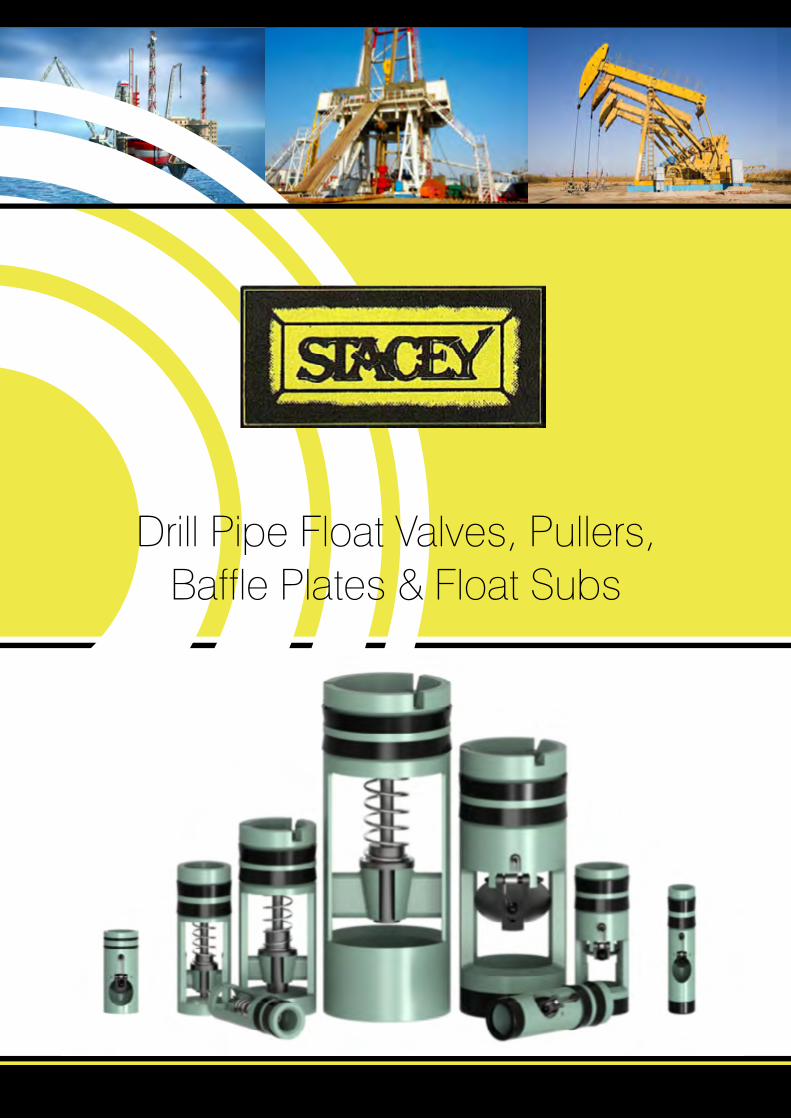
Drill Pipe Float Valves, Pullers, Baffle Plates & Float Subs

Integrated Approach
We work closely with Operators, Drilling Contractors, Well Service Companies, Directional Companies, Milling/Fishing Tool Companies, Coiled Tubing Companies, Rental Tool Companies, along with Consultant Companies.
Customer requirements and input is paramount, allowing us to supply Valves that are specific to the application.
We have an extensive Data Collection Policy, which allows us to monitor, assess and improve our equipment.
We are constantly looking at potential issues that may impact the performance of Float Valves.
Float Valves are run to prevent Drilling Fluids from back flowing up the Drill String to the surface. It is basically a one way or Downhole Check Valve.
Float Valves may be used for additional Well Control and also to protect high cost tools such as Rotary Steerables, MWD/LWD etc from Drilling Fluid, Cuttings and Metal Debris flowing up the Drill String whilst running in the hole.
Brief History Stacey was founded in 1975 on three basic principles, Optimum Safety, Quality Products, and excellent Service. This continues today.
Our products are used throughout the world.

Features
• InvestmentCastLowAlloySteelIntegralCages • Higherimpactproperties=LongerLife • Onepiececonstruction=MorereliableCage • Heattreatedtoahardnessof<22RockwellC • HighTemp & H2S ModelsAvailable • AirSteam&GeothermalModelsAvailable • IntegralPlungerValves • CaseHardenedFlapperValves • InconelSprings–CorrosionResistant • TrackingNumbersasStandard
AllStaceyvalveshavetrackingnumberfortraceabilitypurposes.H2S/HighTemperatureandSteamServiceValvesareavailableinbothFandGModels.
Stacey provides a full line of Float Valves, Repair Kits, Baffle Plates and Valve Puller Tools, cover-ing a wide range of Drilling Conditions, along with MillingandPlugging/Abandonmentoperations.
All Stacey Float Valves are manufactured with alloy steel integral, cages & plungers to produce the most reliable float valve on the market today.AllFlappersareinvestmentcastandthencase hardened for wear resistance. Elastomers available are Nitrile Butadiene (NMB/BUNA N),Hydrogen Nitrile Butadiene HNBR, and Viton(Fluoroelastmer/FKM). Inconel or stainless steelsprings come standard on all our valves and are significantly more resistant to corrosion when compared to standard service springs provided by most other manufacturers.
All Stacey Float Valves, Baffle Plates and ValvePullers are interchangeable with the Baker Style ModelF,andBakerStyleModelGFloatValves.
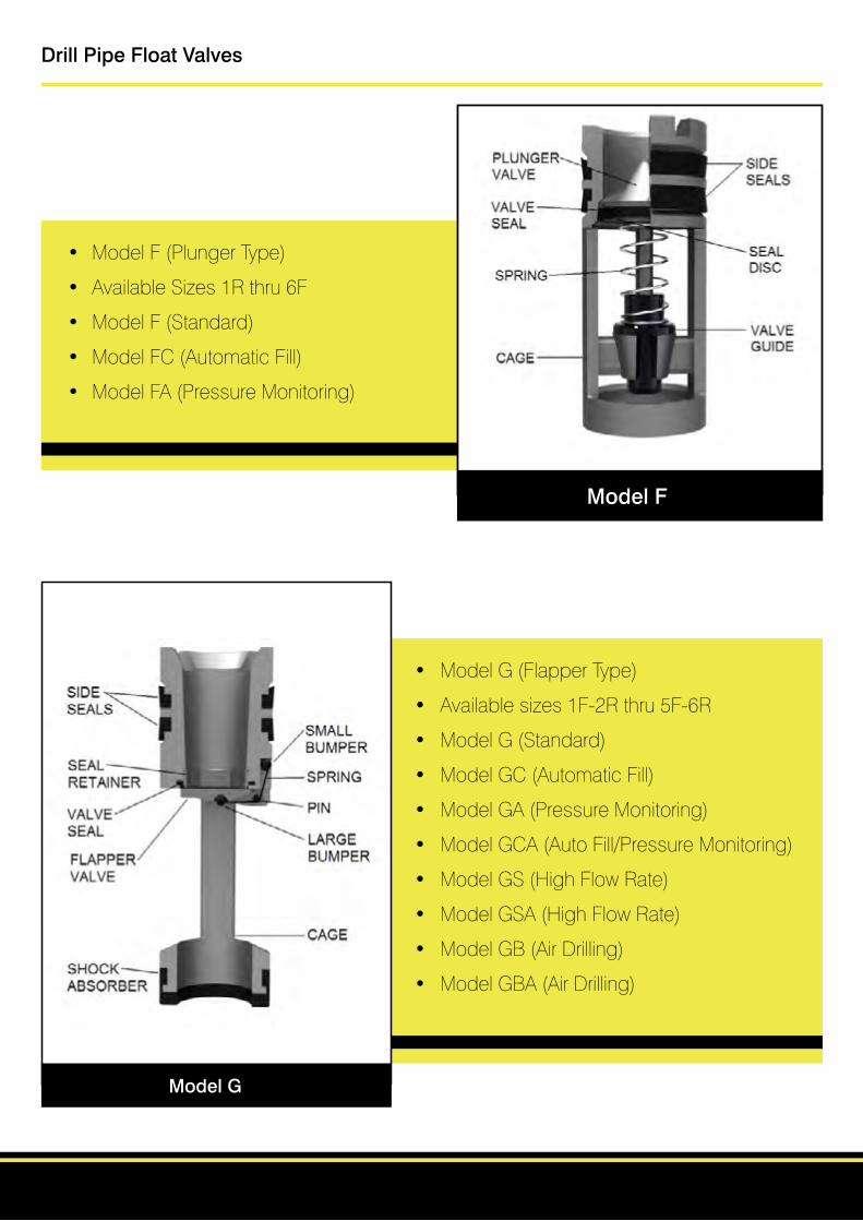
Model F
Model G
Drill Pipe Float Valves
• ModelF(PlungerType)
• AvailableSizes1Rthru6F
• ModelF(Standard)
• ModelFC(AutomaticFill)
• ModelFA(PressureMonitoring)
• ModelG(FlapperType)
• Availablesizes1F-2Rthru5F-6R
• ModelG(Standard)
• ModelGC(AutomaticFill)
• ModelGA(PressureMonitoring)
• ModelGCA(AutoFill/PressureMonitoring)
• ModelGS(HighFlowRate)
• ModelGSA(HighFlowRate)
• ModelGB(AirDrilling)
• ModelGBA(AirDrilling)
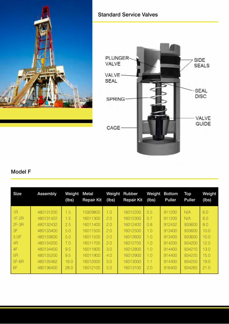
Model F
Size Assembly Weight Metal Weight Rubber Weight Bottom Top Weight (lbs) Repair Kit (lbs) Repair Kit (lbs) Puller Puller (lbs)
1R 480131200 1.5 15929800 1.0 16012200 0.5 911200 N/A 6.01F-2R 480131422 1.5 16011300 2.0 16012300 0.7 911200 N/A 6.02F-3R 480132432 2.5 16011400 2.0 16012400 0.8 912432 933600 8.03F 480133400 5.0 16011500 2.0 16012500 1.0 913400 933600 10.03.5IF 480133600 5.0 16011500 2.0 16012600 1.0 913400 933600 10.04R 480134200 7.0 16011700 2.0 16012700 1.0 914200 934200 12.04F 480134400 9.5 16011800 3.0 16012800 1.0 914400 934210 13.05R 480135200 9.5 16011900 4.0 16012900 1.0 914400 934225 15.05F-6R 480135462 16.0 16012000 5.0 16013000 1.1 914400 934250 19.06F 480136400 28.0 16012100 5.0 16013100 2.0 916400 934265 21.0
Standard Service Valves

Model FA
Size Assembly Weight Metal Weight Rubber Weight Bottom Top Weight (lbs) Repair Kit (lbs) Repair Kit (lbs) Puller Puller (lbs)
1R 480121200 1.5 15929805 1.0 16012200 0.1 911200 N/A 7.01F-2R 480121422 1.5 16011305 1.0 16012300 0.1 911200 N/A 7.02F-3R 480122432 2.5 16011405 2.0 16012400 0.8 912432 933600 8.03F 480123400 5.0 16011505 2.0 16012500 1.0 913400 933600 10.03.5IF 480123600 5.0 16011505 2.0 16012600 1.0 913400 933600 10.04R 480124200 7.0 16011705 2.0 16012700 1.0 914200 934200 12.04F 48012400 9.5 16011805 2.0 16012800 1.0 914400 934210 13.05R 480125200 10.5 16011905 3.5 16012900 10.0 914400 934225 15.05F-6R 480125462 16.0 16012005 5.0 16013005 1.1 914400 934250 19.06F 480126400 28.0 16012105 5.0 16013100 1.2 916400 934265 21.0
Standard Service Valves

Model FC
Size Assembly Weight Metal Weight Rubber Weight Bottom Top Weight (lbs) Repair Kit (lbs) Repair Kit (lbs) Puller Puller (lbs)
2F-3R 480182432 2.5 70017100 2.0 16012400 0.8 912432 933600 8.03F 480183400 5.0 70017300 2.0 16012500 1.0 913400 933600 10.03.5IF 480183600 5.0 70017300 2.0 16012600 1.0 913400 933600 10.04R 480184200 7.0 70017400 2.0 16012700 1.0 914200 934200 12.04F 480184400 9.5 70017500 3.0 16012800 1.0 914400 934210 13.05R 480185200 9.5 70017600 4.0 16012900 1.0 914400 934225 15.05F-6R 480185462 16.0 70017700 5.0 16013000 1.1 914400 934250 19.06F 480186400 28.0 70017800 5.0 16013100 2.0 916400 934265 21.0
Standard Service Valves
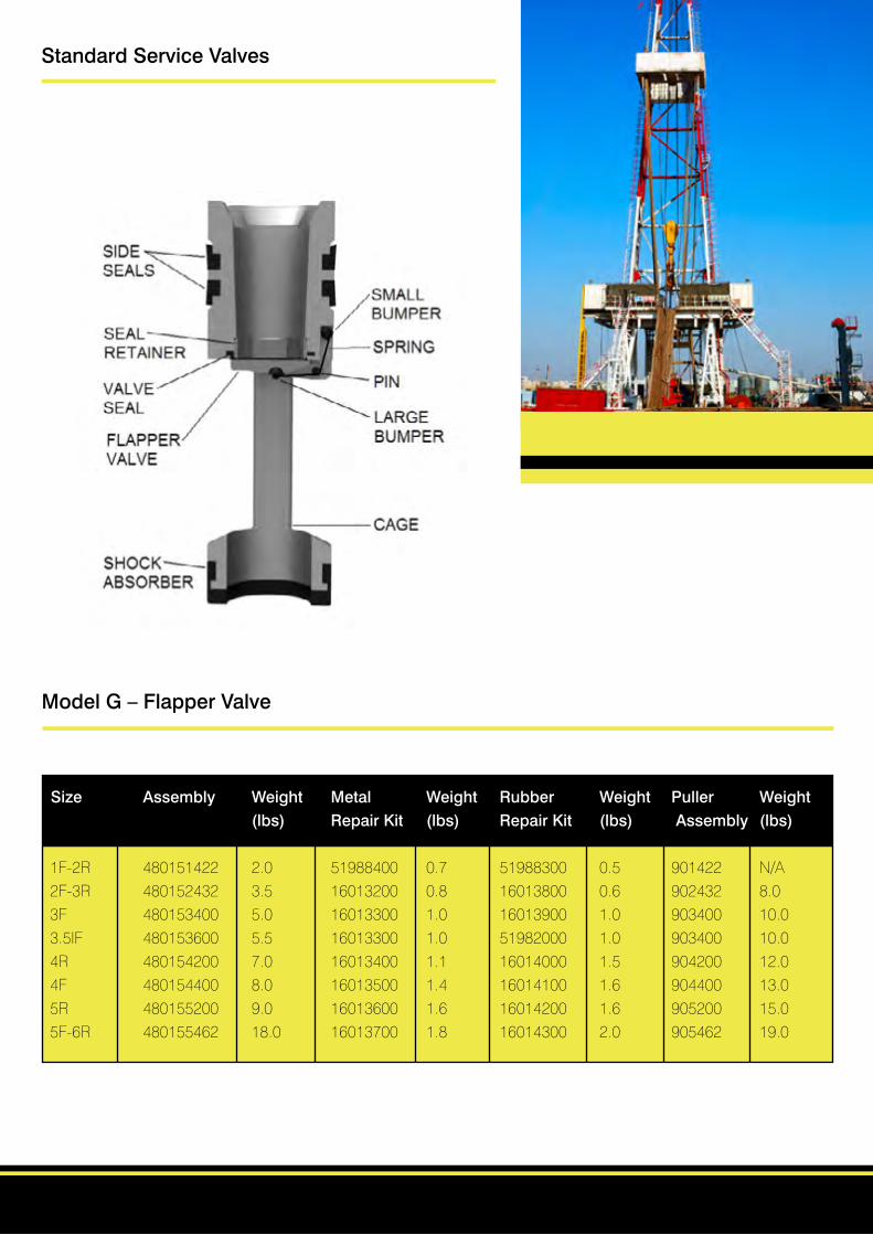
Model G – Flapper Valve
Size Assembly Weight Metal Weight Rubber Weight Puller Weight (lbs) Repair Kit (lbs) Repair Kit (lbs) Assembly (lbs)
1F-2R 480151422 2.0 51988400 0.7 51988300 0.5 901422 N/A2F-3R 480152432 3.5 16013200 0.8 16013800 0.6 902432 8.03F 480153400 5.0 16013300 1.0 16013900 1.0 903400 10.03.5IF 480153600 5.5 16013300 1.0 51982000 1.0 903400 10.04R 480154200 7.0 16013400 1.1 16014000 1.5 904200 12.04F 480154400 8.0 16013500 1.4 16014100 1.6 904400 13.05R 480155200 9.0 16013600 1.6 16014200 1.6 905200 15.05F-6R 480155462 18.0 16013700 1.8 16014300 2.0 905462 19.0
Standard Service Valves
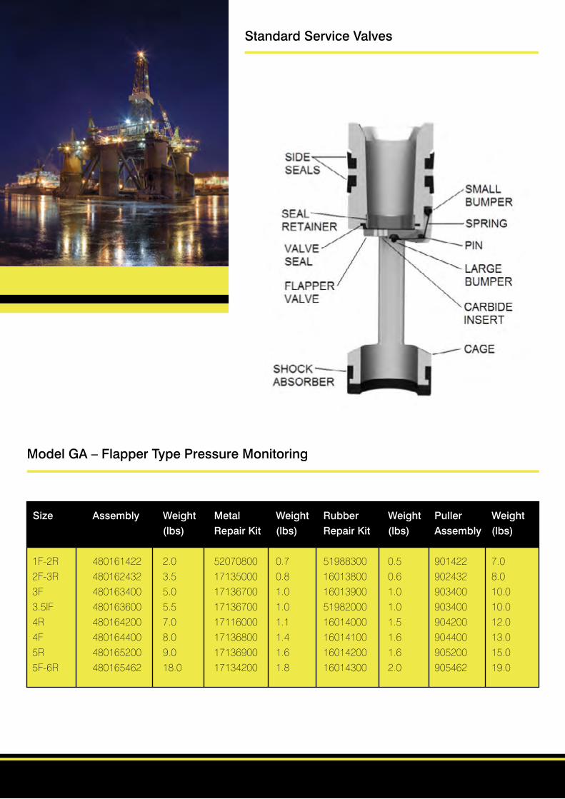
Model GA – Flapper Type Pressure Monitoring
Size Assembly Weight Metal Weight Rubber Weight Puller Weight (lbs) Repair Kit (lbs) Repair Kit (lbs) Assembly (lbs)
1F-2R 480161422 2.0 52070800 0.7 51988300 0.5 901422 7.02F-3R 480162432 3.5 17135000 0.8 16013800 0.6 902432 8.03F 480163400 5.0 17136700 1.0 16013900 1.0 903400 10.03.5IF 480163600 5.5 17136700 1.0 51982000 1.0 903400 10.04R 480164200 7.0 17116000 1.1 16014000 1.5 904200 12.04F 480164400 8.0 17136800 1.4 16014100 1.6 904400 13.05R 480165200 9.0 17136900 1.6 16014200 1.6 905200 15.05F-6R 480165462 18.0 17134200 1.8 16014300 2.0 905462 19.0
Standard Service Valves

Model GC – Flapper Type Automatic Fill
Size Assembly Weight Metal Weight Rubber Weight Puller Weight (lbs) Repair Kit (lbs) Repair Kit (lbs) Assembly (lbs)
2F-3R 480192432 3.5 16013200 0.8 16013800 0.6 902432 8.03F 480193400 5.0 16013300 1.0 16013900 1.0 903400 10.03.5IF 480193600 5.5 16013300 1.0 51982000 1.0 903400 10.04R 480194200 7.0 16013400 1.1 16014000 1.5 904200 12.04F 480194400 8.0 16013500 1.4 16014100 1.6 904400 13.05R 480195200 9.0 16013600 1.6 16014200 1.6 905200 15.05F-6R 480195462 18.0 16013700 1.8 16014300 2.0 905462 19.0
Standard Service Valves
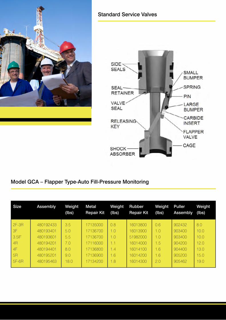
Model GCA – Flapper Type-Auto Fill-Pressure Monitoring
Size Assembly Weight Metal Weight Rubber Weight Puller Weight (lbs) Repair Kit (lbs) Repair Kit (lbs) Assembly (lbs)
2F-3R 480192433 3.5 17135000 0.8 16013800 0.6 902432 8.03F 480193401 5.0 17136700 1.0 16013900 1.0 903400 10.03.5IF 480193601 5.5 17136700 1.0 51982000 1.0 903400 10.04R 480194201 7.0 17116000 1.1 16014000 1.5 904200 12.04F 480194401 8.0 17136800 1.4 16014100 1.6 904400 13.05R 480195201 9.0 17136900 1.6 16014200 1.6 905200 15.05F-6R 480195463 18.0 17134200 1.8 16014300 2.0 905462 19.0
Standard Service Valves
Model FA
Model FC
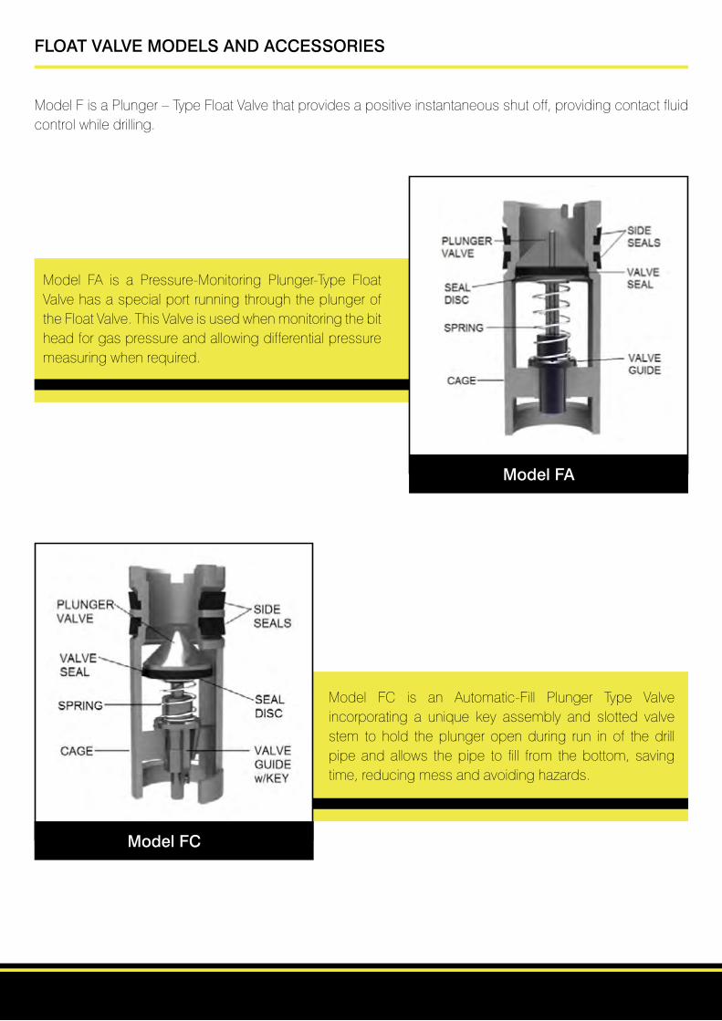
FLOAT VALVE MODELS AND ACCESSORIES
ModelFisaPlunger–TypeFloatValvethatprovidesapositiveinstantaneousshutoff,providingcontactfluidcontrol while drilling.
Model FA is a Pressure-Monitoring Plunger-Type FloatValve has a special port running through the plunger of the Float Valve. This Valve is used when monitoring the bit head for gas pressure and allowing differential pressure measuring when required.
Model FC is an Automatic-Fill Plunger Type Valve incorporating a unique key assembly and slotted valve stem to hold the plunger open during run in of the drill pipe and allows the pipe to fill from the bottom, saving time,reducingmessandavoidinghazards.

Model GC
Model GA
ModelGB–AirDrillingValve
ModelGBA–AirDrillingwithDifferentialPressureMonitoring Valve
ModelGAisaPressure-MonitoringFlapper-TypeValve,itisindistinguishablefromtheModelGwiththeexceptionof a tungsten-Carbide insert in the Flapper Valve.
ModelG isaFlapper-TypeFloatValve that,whenopenedoffers an unobstructed bore through the Float Valve.
ModelGCisanAutomatic-FillFlapper-TypeFloatValvewhich incorporates a unique self-raising key assembly that holds the flapper partially open during run in, allowing the pipe to fill from the bottom.
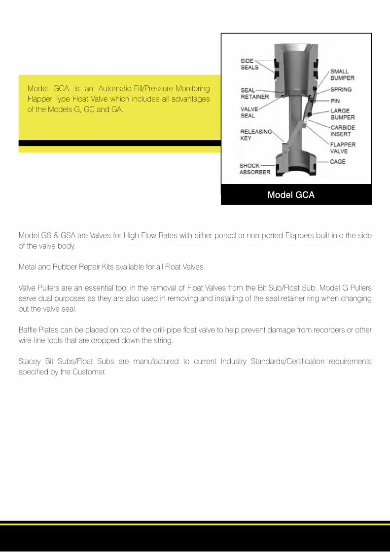
Model GCA
ModelGS&GSAareValvesforHighFlowRateswitheitherportedornonportedFlappersbuiltintothesideof the valve body.
Metal and Rubber Repair Kits available for all Float Valves.
ValvePullersareanessentialtoolintheremovalofFloatValvesfromtheBitSub/FloatSub.ModelGPullersserve dual purposes as they are also used in removing and installing of the seal retainer ring when changing out the valve seal.
Baffle Plates can be placed on top of the drill-pipe float valve to help prevent damage from recorders or other wire-line tools that are dropped down the string.
Stacey Bit Subs/Float Subs are manufactured to current Industry Standards/Certification requirements specified by the Customer.
Model GCA is an Automatic-Fill/Pressure-MonitoringFlapper Type Float Valve which includes all advantages oftheModelsG,GCandGA.

H2S/High Temp Service Valves
Model F – Plunger Type - H2S/High Temp Service Valves
Size Assembly Weight Metal Weight Rubber Weight Top Weight Bottom Weight
(lbs) Repair (lbs) Repair (lbs) Puller (lbs) Puller (lbs)
Kit Kit Assembly Assembly
1R 480301200 1.5 15929800 1.0 71081701 0.5 N/A N/A 911200 6.0
1F-2R 480301422 1.5 16011300 2.0 71081801 0.7 N/A N/A 911200 6.0
2F-3R 480302432 2.5 16011400 2.0 71081901 0.8 933600 8.0 912432 8.0
3F 480303400 5.0 16011500 2.0 71082001 1.0 933600 10.0 913400 10.0
3.5IF 480303600 5.0 16011500 2.0 71082101 1.0 933600 10.0 913400 10.0
4R 480304200 7.0 16011700 2.0 71082201 1.0 934200 12.0 914200 12.0
4F 480304400 9.5 16011800 3.0 71082301 1.0 934210 13.0 914400 13.0
5R 480305200 9.5 16011900 4.0 71082401 1.0 934225 15.0 914400 15.0
5F-6R 480305462 16.0 16012000 5.0 71082501 1.1 934250 19.0 914400 19.0
6F 480306400 28.0 16012100 5.0 71082601 2.0 934265 21.0 916400 21.0
Model FA – Plunger Type – Pressure Monitoring - H2S/High Temp Service Valves
Size Assembly Weight Metal Weight Rubber Weight Top Weight Bottom Weight
(lbs) Repair (lbs) Repair (lbs) Puller (lbs) Puller (lbs)
Kit Kit Assembly Assembly
2F-3R 480352432 2.5 16011405 2.0 71081901 0.8 933600 8.0 912432 8.0
3F 480353400 5.0 16011505 2.0 71082001 1.0 933600 10.0 913400 10.0
3.5IF 480353600 5.0 16011505 2.0 71082101 1.0 933600 10.0 913400 10.0
4R 480354200 7.0 16011705 2.0 71082201 1.0 934200 12.0 914200 12.0
5F-6R 480355462 16.0 16012005 5.0 71082501 1.1 934250 19.0 914400 19.0

H2S/High Temp Service Valves
Model G – Flapper Type – H2S/High Temp Service Valves
Size Assembly Weight Metal Weight Rubber Weight Puller Weight (lbs) Repair Kit (lbs) Repair Kit (lbs) Assembly (lbs)
1F-2R 480311422 2.0 51997300 0.7 51997200 0.5 901422 N/A2F-3R 480312432 3.5 71085901 0.8 71082701 0.6 902432 8.03F 480313400 5.0 71086001 1.0 71082801 1.0 903400 10.03.5IF 480313600 5.5 71086001 1.0 71082801 1.0 903400 10.04R 480314200 7.0 71086101 1.1 52125001 1.5 904200 12.04F 480314400 8.0 71086201 1.4 71083001 1.6 904400 13.05R 480315200 9.0 71086301 1.6 71083101 1.6 905200 15.05F-6R 480315462 18.0 71086401 1.8 71083201 2.0 905462 19.0
Model GA – Flapper Type – Pressure Monitoring - H2S/High Temp Service Valves
Size Assembly Weight Metal Weight Rubber Weight Puller Weight (lbs) Repair Kit (lbs) Repair Kit (lbs) Assembly (lbs)
1F-2R 480261422 2.0 52070801 0.7 51997200 0.5 901422 7.02F-3R 480262432 3.5 17135001 0.8 71082701 0.6 902432 8.03F 480263400 5.0 17136701 1.0 71082801 1.0 903400 10.03.5IF 480263600 5.0 17136701 1.0 52125001 1.0 903400 10.04R 480264200 7.0 17116001 1.1 71082901 1.5 904200 12.04F 480264400 8.0 17136801 1.4 71083001 1.6 904400 13.05R 480265200 9.0 17136901 1.6 71083101 1.6 905200 15.05F-6R 480265462 12.0 17134201 1.8 71083201 2.0 905462 19.0
Model GC – Flapper Type – Automatic Fill - H2S/High Temp Service Valves
Size Assembly Weight Metal Weight Rubber Weight Puller Weight (lbs) Repair Kit (lbs) Repair Kit (lbs) Assembly (lbs)
2F-3R 480332432 3.5 71085901 0.8 16013800 0.6 902432 8.03F 480333400 5.0 71086001 1.0 16013900 1.0 903400 10.03.5IF 480333600 5.0 71086001 1.0 52125001 1.0 903400 10.04R 480334200 7.0 71086101 1.1 16014000 1.5 904200 12.04F 480334400 8.0 71086201 1.4 16014100 1.6 904400 13.05R 480335200 9.0 71086301 1.6 16014200 1.6 905200 15.05F-6R 480335462 12.0 71086401 1.8 16014300 2.0 905462 19.0

Model F DPFV
Model F DPFV
Rubber Repair Kit F/Model F DPFV
RefertoModelNoofValve, when ordering, for correct Repair Kit
Metal Repair Kit F/Model F DPFV
RefertoModelNoofValve, when ordering, for correct Repair Kit
Model G DPFV
Model G DPFV
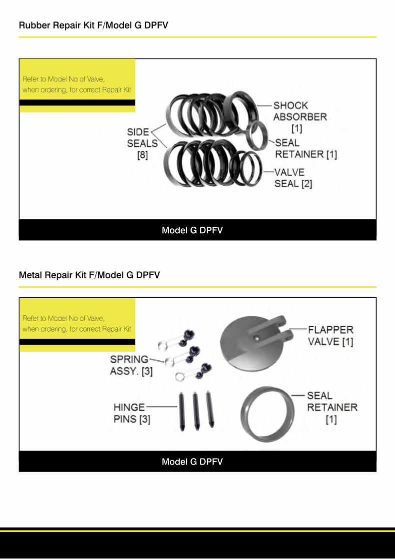
Rubber Repair Kit F/Model G DPFV
RefertoModelNoofValve, when ordering, for correct Repair Kit
Metal Repair Kit F/Model G DPFV
RefertoModelNoofValve, when ordering, for correct Repair Kit
Model G DPFV
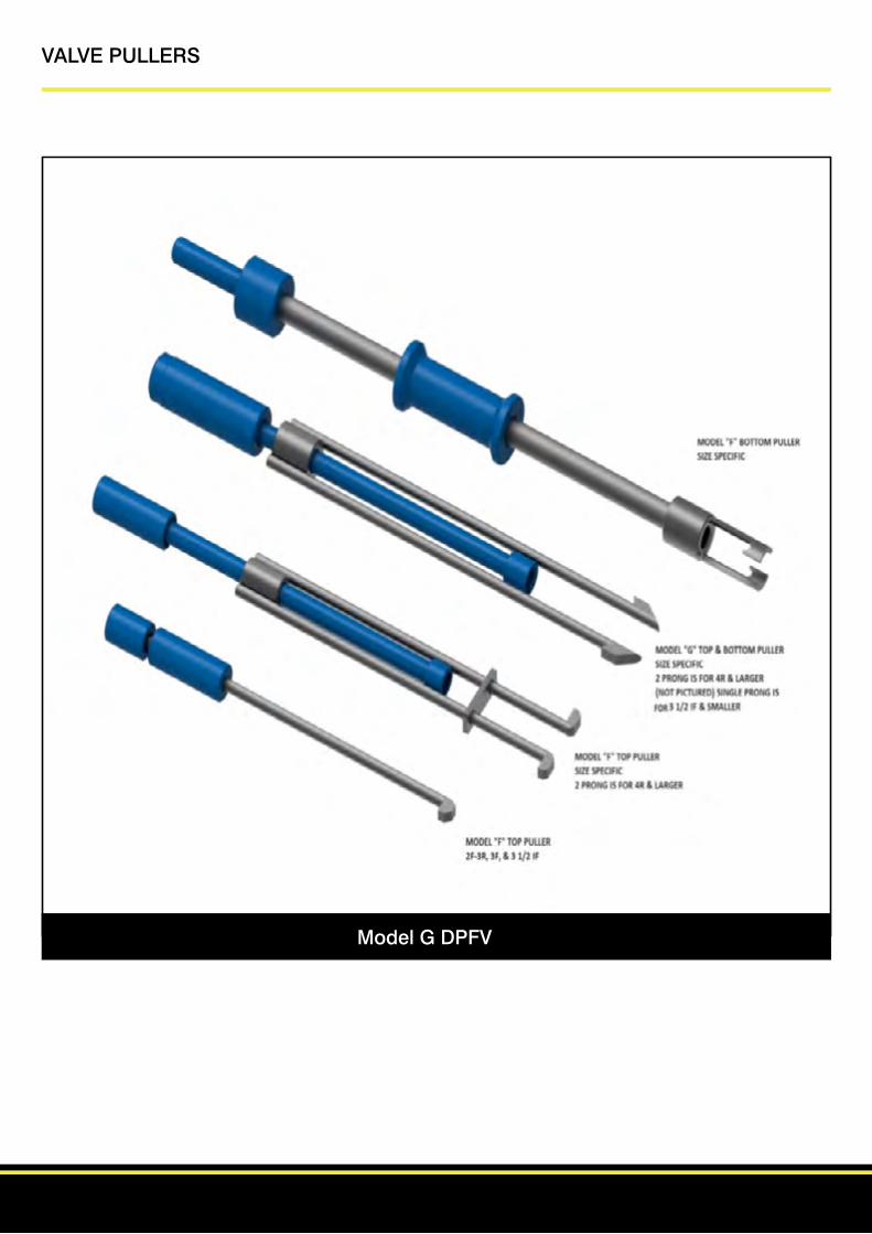
VALVE PULLERS

Installation Guide for Drill Pipe Float Valves
1.ThefirststepistodeterminethesizeoftheDrillPipeFloatValve(DPFV)tobeinstalledaccordingtothesizeand type of connection they are being installed into. Charts are available to guide this selection.
2.VisuallyinspecttheboreoftheFloatSubordrilledoutdrillcollarforshavingsand/orforeignobjectsthatcoulddam age the seals of the DPFV. Clean out as necessary.
3.LubricatethesidesealsoftheDPFVusinghydraulicoil(forinstallationpurposesonly,grade,brand,orviscosityis notimportant)andinsertintotheboreofthefloatsuborthedrilledoutdrillcollar(rotatingtheDPFVslightlywhile inserting will lessen the force required and the chances of damaging the side seals. Caution must be taken to en surethattheDPFVisalwaysinstalledwiththetopofthevalvefacingupwardsinthestring.(seefigure:1)
CAUTIONS
1. The top of the DPFV must be facing upward in the string. 2. Fillthedrillpiperegularlywhilerunning(tripping)in. 3. If running multiple DPFV’s in the same string it is recommended they be separated.
Figure 1:

Removal of Drill Pipe Float Valves
Model F valves
ModelF(TOP)PullerisusedforremovingModelFValvesfromthetopofthesub.Justsqueezetheforkstogetherandpress against the head of the valve plunger. Once the forks are engaged with the cage the valve can be pulled. Disengage byslidingtheseparatorawayfromthevalveandsqueezingtheforkstogetherandthepullercanberemoved.
ModelF(BOTTOM)Pullermakeseasyworkofremovingstuckortightfloatvalvesfromthesubordrillcollar.Justengagethe special catch into the bottom of the float valve, rotate 90 degree’s and slide bumper into the stop and the float valve is removed.
Model F Valves (continued)
Note:Whenusing theModelF (BOTTOM)Puller to remove theModelFCValve,specialcaremustbe takenwhen engaging the catch so that is does not make contact with the releasing key.
Model G Valves
TheModelGValvePullerisadualpurposetool,asidefromremovingtightorstuckfloatvalvesfromsubsordrillcollars,it also assists in removing and installing the seal retaining ring.
TheModelGValvePullerisusedinasimilarfashiontotheotherpullers,byengagingthecageofthevalvewiththeforksand then quickly pulling the driver upward to remove the valve
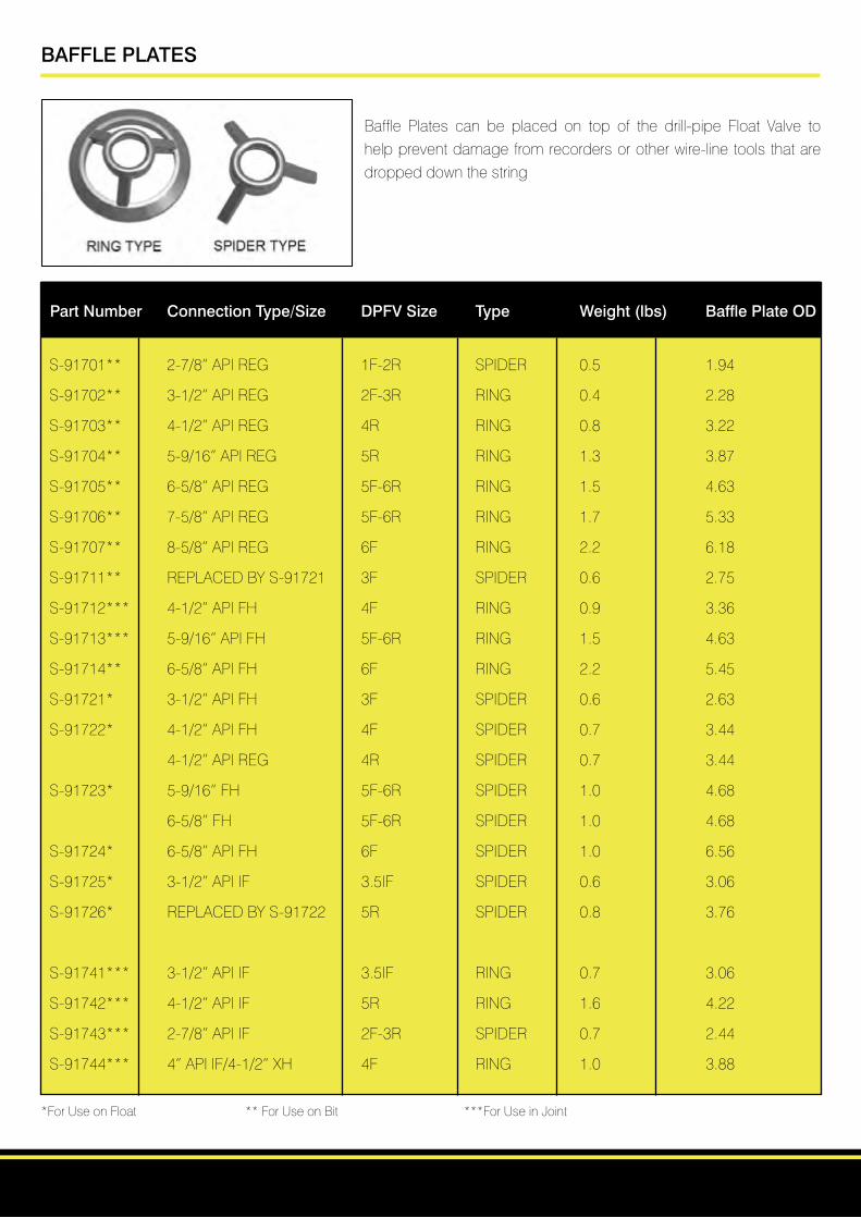
BAFFLE PLATES
Baffle Plates can be placed on top of the drill-pipe Float Valve to help prevent damage from recorders or other wire-line tools that are dropped down the string
Part Number Connection Type/Size DPFV Size Type Weight (lbs) Baffle Plate OD
S-91701** 2-7/8”APIREG 1F-2R SPIDER 0.5 1.94
S-91702** 3-1/2”APIREG 2F-3R RING 0.4 2.28
S-91703** 4-1/2”APIREG 4R RING 0.8 3.22
S-91704** 5-9/16”APIREG 5R RING 1.3 3.87
S-91705** 6-5/8”APIREG 5F-6R RING 1.5 4.63
S-91706** 7-5/8”APIREG 5F-6R RING 1.7 5.33
S-91707** 8-5/8”APIREG 6F RING 2.2 6.18
S-91711** REPLACEDBYS-91721 3F SPIDER 0.6 2.75
S-91712*** 4-1/2”APIFH 4F RING 0.9 3.36
S-91713*** 5-9/16”APIFH 5F-6R RING 1.5 4.63
S-91714** 6-5/8”APIFH 6F RING 2.2 5.45
S-91721* 3-1/2”APIFH 3F SPIDER 0.6 2.63
S-91722* 4-1/2”APIFH 4F SPIDER 0.7 3.44
4-1/2”APIREG 4R SPIDER 0.7 3.44
S-91723* 5-9/16”FH 5F-6R SPIDER 1.0 4.68
6-5/8”FH 5F-6R SPIDER 1.0 4.68
S-91724* 6-5/8”APIFH 6F SPIDER 1.0 6.56
S-91725* 3-1/2”APIIF 3.5IF SPIDER 0.6 3.06
S-91726* REPLACEDBYS-91722 5R SPIDER 0.8 3.76
S-91741*** 3-1/2”APIIF 3.5IF RING 0.7 3.06
S-91742*** 4-1/2”APIIF 5R RING 1.6 4.22
S-91743*** 2-7/8”APIIF 2F-3R SPIDER 0.7 2.44
S-91744*** 4”APIIF/4-1/2”XH 4F RING 1.0 3.88 *ForUseonFloat **ForUseonBit ***ForUseinJoint
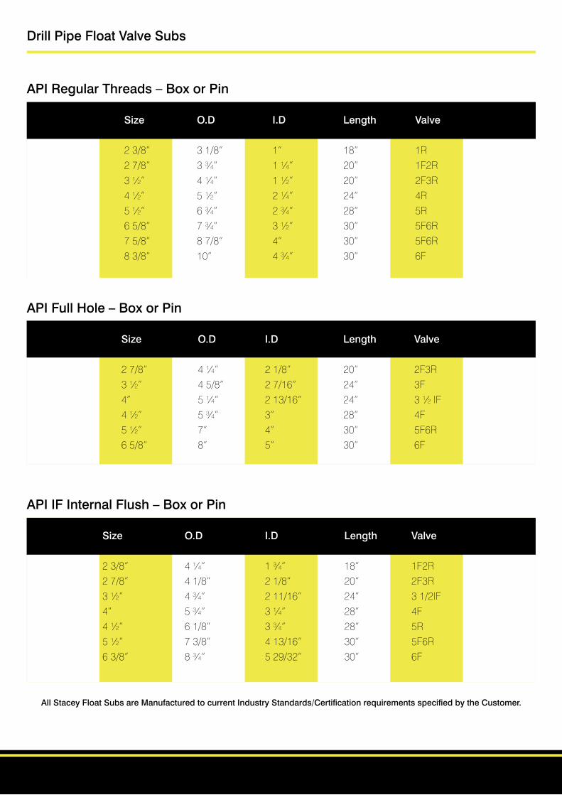
Drill Pipe Float Valve Subs
API Regular Threads – Box or Pin
Size O.D I.D Length Valve
23/8” 31/8” 1” 18” 1R 27/8” 3¾” 1¼” 20” 1F2R 3½” 4¼” 1½” 20” 2F3R 4½” 5½” 2¼” 24” 4R 5½” 6¾” 2¾” 28” 5R 65/8” 7¾” 3½” 30” 5F6R 75/8” 87/8” 4” 30” 5F6R 83/8” 10” 4¾” 30” 6F
API Full Hole – Box or Pin
Size O.D I.D Length Valve
27/8” 4¼” 21/8” 20” 2F3R 3½” 45/8” 27/16” 24” 3F 4” 5¼” 213/16” 24” 3½IF 4½” 5¾” 3” 28” 4F 5½” 7” 4” 30” 5F6R 65/8” 8” 5” 30” 6F
API IF Internal Flush – Box or Pin
Size O.D I.D Length Valve
23/8” 4¼” 1¾” 18” 1F2R 27/8” 41/8” 21/8” 20” 2F3R 3½” 4¾” 211/16” 24” 31/2IF 4” 5¾” 3¼” 28” 4F 4½” 61/8” 3¾” 28” 5R 5½” 73/8” 413/16” 30” 5F6R 63/8” 8¾” 529/32” 30” 6F
All Stacey Float Subs are Manufactured to current Industry Standards/Certification requirements specified by the Customer.
Drill Pipe Float Valve Subs
Dimensional Data
Diameter Length Diameter Model G Model F Size Valve Diameter of Recess for of Valve of Recess I.D. of Valve I.D. of Valve of Valve Valve for TOTCO Spider
N/A 1 1R 121/32 111/16 57/8 15/161 1¼ 1F2R 129/32 115/16 6¼ 1½1¼ 19/16 2F3R 213/32 27/16 6½ 129/3215/8 17/8 3F 213/16 227/32 10 27/1615/8 17/8 31/2IF 31/8 35/32 10 211/16131/32 25/16 4R 315/32 3½ 85/16 215/1623/16 2½ 4F 321/32 311/16 12 3¼2¼ 2¾ 5R 37/8 329/32 9¾ 33/827/8 3¼ 5F6R 425/32 413/16 11¾ 49/32N/A 41/8 6F 511/16 523/32 145/8 53/16
All Stacey Float Subs are Manufactured to current Industry Standards/Certification requirements specified by the Customer.

BIT SUB INFORMATION
Valve Size Thread Size Tool Joint Type Standard OD Face to Shoulder OR Face to Face
1R 2-3/8” APIREGULAR 3-1/8” 18”1F-2R 2-7/8” 3-3/4” 20”2F-3R 3-1/2” 4-1/4” 20”4R 4-1/2” 5-1/2” 24”5R 5-1/2” 6-3/4” 28”5F-6R 6-5/8” 7-3/4” 30”5F-6R 7-5/8” 8-7/8” 30”6F 8-5/8” 10” 30”
3F 3-1/2” APIFULLHOLE 4-5/8” 24”3.5IF 4” 5-1/4” 24”4F 4-1/2” 5-3/4” 28”5F-6R 5-1/2” 7” 30”6F 6-5/8” 8” 30”
1F-2R 2-3/8” APIIF 3-3/8” 18”
2F-3R 2-7/8” APIBOXXPIN 4-1/8” 20”
3.5IF 3-1/2” APIIF 4-3/4” 24”4F 4” 5-3/4” 28”5R 4-1/2” 6-3/8” 28”5F-6R 5-1/2” 7-3/8” 30”6F 6-5/8” 8-3/4” 30”
The information guide above is for reference purposes only. Please use appropriate API specification when manufacturing subs.
BIT AND SHANK CHART
Bit 3- 3- 4- 4- 5- 6 6- 6- 6- 7- 8- 8- 8- 9- 9- 10- 11 12- 13- 20 24 25
Size 4/1 3/8 1/2 3/4 1/2 1/8 1/4 3/4 7/8 1/4 1/2 3/4 1/2 3/4 1/2 1/4 1/2
(in.)
Std
API
Pin 2- 2- 2- 2- 3- 3- 3- 3- 3- 4- 4- 4- 4- 6- 6- 6- 6- 6- 6- 7- 7- 7-
Shank 3/8 3/8 3/8 7/8 1/2 1/2 1/2 1/2 1/2 1/2 1/2 1/2 1/2 5/8 5/8 5/8 5/8 5/8 5/8 5/8 5/8 5/8
Size
(in.)
All Stacey Bit Subs are Manufactured to current Industry Standards/Certification requirements specified by the Customer.
TOOL JOINT SPECIFICATION
Tool Joint Types Model Sizes
1R 1R-2R 2F-3R 3F 3.5IF 4R 4F 5R 5F-6R 6F
API 2-3/8” 2-7/8” 3-1/2” 4-1/2” 5-1/2” 6-5/8” 8-5/8”REGULAR 5-9/16”* 7-5/8”+
HUGHESOR 2-3/8” 2-7/8” 3-1/2” 4-1/2” 5-1/2” 6-5/8” 8-5/8”REEDACME 5-9/16”
UNIONTOOL 2-3/8” 2-7/8” 4-1/2” 5-1/2” 6-5/8”+ 3-1/2” 5-9/16”*
HUGHESORREED 2-7/8” 3-1/2” 4”4-1/2” 5” 5-1/2”DOUBLESTREAM-LINE 2-3/8” 5-9/16”*
APIFULLHOLE 2-3/8” 2-7/8” 3-1/2” 4” 4-1/2” 4-1/2”* 6-5/8”*
REEDACME 3-1/2”* 4-1/2”* 5-1/2”FULLHOLE 5-9/16”*
HUGHESACME 2-3/8” 2-7/8” 3-1/2”* 4-1/2”* 5-1/2”STREAMLINE 5-9/16”*
HUGHESXTRAHOLE 2-7/8” 3-1/2” 4-1/2” 5” 5-1/2” 5-9/16”*
REEDSEMI-INTERNAL 2-7/8” 3-1/2” 4-1/2” 5”FLUSH
APIINTERNALFLUSH 2-3/8” 2-7/8” 3-1/2” 4” 4-1/2”*
HYDRILTYPEIF 2-3/8”* 2-7/8”* 3-1/2”* 4-1/2” 5”(INT.FLUSHEXT.UP-SET)
HYDRILEIU 3-1/2” 4” 4-1/2” 5-1/2” 6-5/8”(EXT.INT.UPSET) 5-9/16”*
HYDRILTYPEF 2-7/8” 4-1/2”5” 5-1/2” 6-5/8”(EXT.FLUSH) 3-1/2”* 5-9/16”
HUGHESEXT. 3-1/2” 4-1/2” 5-1/2” 6-5/8”FLUSHACME 5-9/16”
HUGHESEXT.FLUSH 4-1/2” FULLHOLE
*IndicatesthatthefloatsubsidthesesizeshaveasmallerID.+Indicatesinterchangeability.ModelsGandGA,areavailableinsizes1F-2Rthru5F-6R,ModelsGCandGCAareavailableinsizes2F-3Rthru5F-6R.ModelsFandFAareavailableinallsizes.ModelFCisavailableinsizes2Fthru6F

Stacey Oil Services LtdUnitAJBadentoyCrescentBadentoy Park Ind EstPortlethen,Aberdeen,AB124YDTel:+44(0)1224781887Mobile:+44(0)7726700856Email:[email protected]
Stacey Oil Service & Rental Tools LLC PO Box 1580 479273USHwy64Roland OK 74954 Tel:1-918-427-3940 Mobile:1-479-461-9032Email:[email protected]