drill hydraulics
TRANSCRIPT
8/18/2019 Drill Hydraulics
http://slidepdf.com/reader/full/drill-hydraulics 1/39
1
PETE 411Well Drilling
Lesson 10Drilling Hydraulics (cont’d)

8/18/2019 Drill Hydraulics
http://slidepdf.com/reader/full/drill-hydraulics 2/39
2
10. Drilling Hydraulics (cont’d)
Effect of Buoyancy on BucklingThe Concept of Stability ForceStability AnalysisMass BalanceEnergy BalanceFlow Through Nozzles
Hydraulic Horsepower Hydraulic Impact Force

8/18/2019 Drill Hydraulics
http://slidepdf.com/reader/full/drill-hydraulics 3/39

8/18/2019 Drill Hydraulics
http://slidepdf.com/reader/full/drill-hydraulics 4/39
4
Bucklingof
Tubulars l
l
Slender pipe
suspendedin wellbore
Partiallybuckledslender
pipe
Neutral Point
Neutral Point
F h - F b
F h
F b

8/18/2019 Drill Hydraulics
http://slidepdf.com/reader/full/drill-hydraulics 5/39
5
Buckling of Tubulars
l
NeutralPoint
NeutralPoint
• Long slender columns, like DP,have low resistance tobending and tend to fail by
buckling if...• Force at bottom (F b) causes
neutral point to move up• What is the effect of buoyancy
on buckling?• What is NEUTRAL POINT?
F b

8/18/2019 Drill Hydraulics
http://slidepdf.com/reader/full/drill-hydraulics 6/39
6
What is NEUTRAL POINT?
l
NeutralPoint
NeutralPoint
• One definition of NEUTRALPOINT is the point abovewhich there is no tendencytowards buckling
• Resistance to buckling isindicated, in part, by:
The Moment of Inertia
444
64I ind d n

8/18/2019 Drill Hydraulics
http://slidepdf.com/reader/full/drill-hydraulics 7/39
7
Consider thefollowing :
19.5 #/ft drillpipeDepth = 10,000 ft.Mud wt. = 15 #/gal.
P HYD = 0.052 (MW) (Depth)
= 0.052 * 15 * 10,000 P HYD = 7,800 psi
Axial tensile stress in pipe at bottom
= - 7,800 psi
What is the axial force at bottom?

8/18/2019 Drill Hydraulics
http://slidepdf.com/reader/full/drill-hydraulics 8/39
8
What is the axial force at bottom?
Cross-sectional area of pipe= (19.5 / 490) * (144/1) = 5.73 in 2
Axial compressive force = pA
= 44,700 lbf.
Can this cause the pipe to buckle?
22 73.5800,7 in
inlbf

8/18/2019 Drill Hydraulics
http://slidepdf.com/reader/full/drill-hydraulics 9/39
9
Axial Tension:
FT = W1 - F2
FT = w x - P 2 (AO - Ai )
At surface, FT = 19.5 * 10,000 - 7,800 (5.73)
= 195,000 - 44,694
= 150,306 lbf.
At bottom, FT = 19.5 * 0 - 7,800 (5.73)
= - 44,694 lbf
Same as before!
FT
F2

8/18/2019 Drill Hydraulics
http://slidepdf.com/reader/full/drill-hydraulics 10/39
10
Stability Force:
FS = A ip i - A O p O
F S = (A i - A O) p (if p i = p O)
At surface, FS = - 5.73 * 0 = 0
At bottom, FS = (-5.73) (7,800) = - 44,694 lbs
THE NEUTRAL POINT is where F S = F T
Therefore, Neutral point is at bottom!PIPE WILL NOT BUCKLE!!
i

8/18/2019 Drill Hydraulics
http://slidepdf.com/reader/full/drill-hydraulics 11/39
8/18/2019 Drill Hydraulics
http://slidepdf.com/reader/full/drill-hydraulics 12/39
12
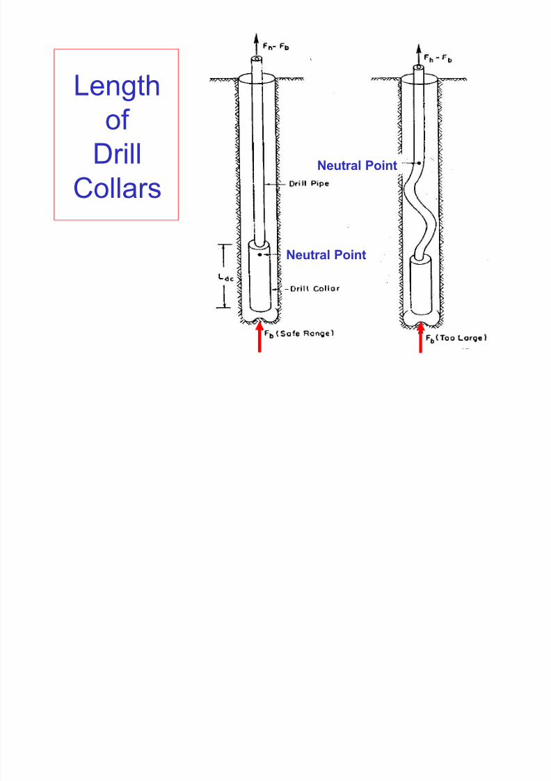
LengthofDrill
Collars
Neutral Point
Neutral Point

8/18/2019 Drill Hydraulics
http://slidepdf.com/reader/full/drill-hydraulics 13/39
13
Length of Drill Collars
ft /lbf
lbf WF
LDC
BITDCIn Air:
In Liquid:
In Liquidwith S.F.:(e.g., S.F =1.3)
s
f DC
BITDC
W
.F.S*FL
1
ft /lbf lbf
W
FL
s
f DC
BITDC
1
8/18/2019 Drill Hydraulics
http://slidepdf.com/reader/full/drill-hydraulics 14/39
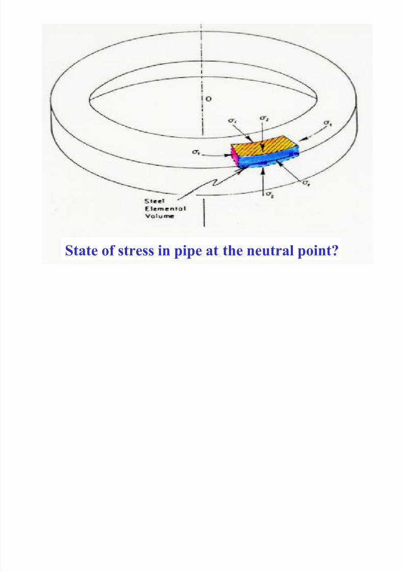
14State of stress in pipe at the neutral point?

8/18/2019 Drill Hydraulics
http://slidepdf.com/reader/full/drill-hydraulics 15/39
15
At the Neutral Point:
The axial stress is equal to the averageof the radial and tangential stresses.
2
t r Z

8/18/2019 Drill Hydraulics
http://slidepdf.com/reader/full/drill-hydraulics 16/39
16
Stability Force:
F S = A i P i - A o P o
If F S > axial tension thenthe pipe may buckle.
If F S < axial tension thenthe pipe will NOT buckle.
F S
F T
0 F T

8/18/2019 Drill Hydraulics
http://slidepdf.com/reader/full/drill-hydraulics 17/39
17
At the neutral point:
FS = axial load
To locate the neutral point:
Plot F S vs. depth on“axial load ( FT ) vs. depth plot”
The neutral point is located where thelines intersect.
8/18/2019 Drill Hydraulics
http://slidepdf.com/reader/full/drill-hydraulics 18/39
18
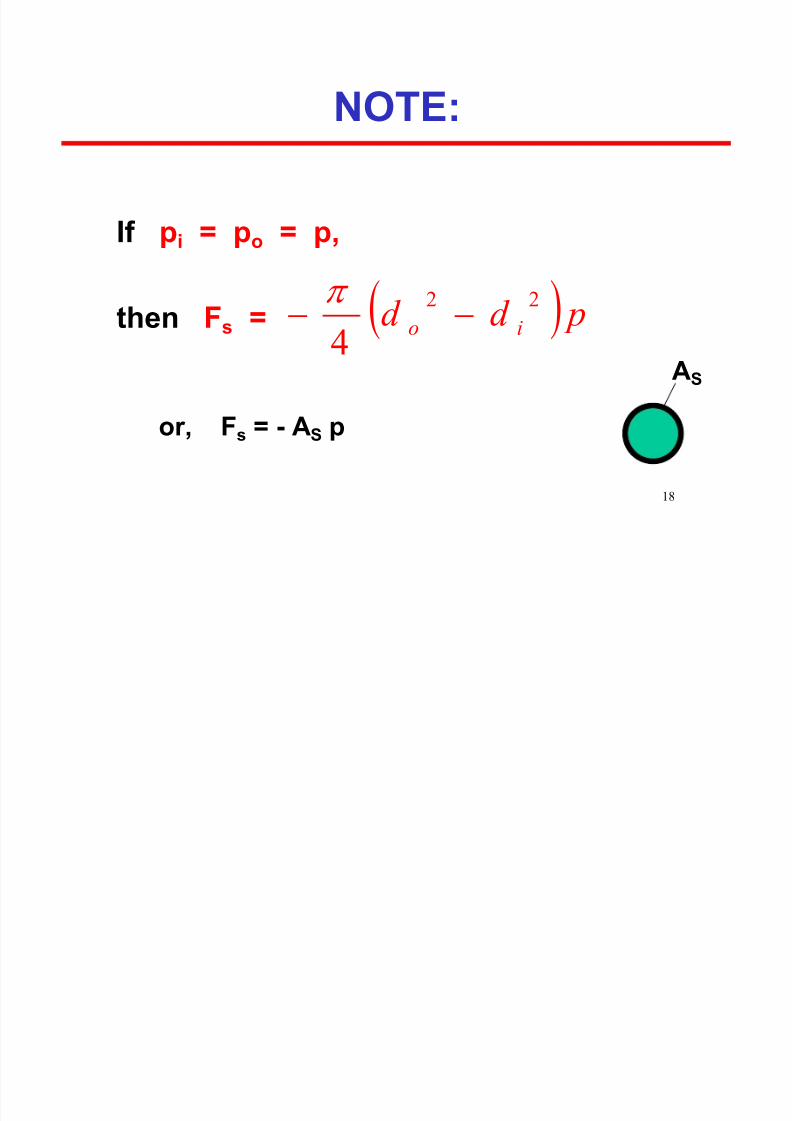
NOTE:
If p i = p o = p,
then F s = pd d io
22
4
or, F s = - A S p
AS

8/18/2019 Drill Hydraulics
http://slidepdf.com/reader/full/drill-hydraulics 19/39
19
Axial Load with F BIT = 68,000 lbf

8/18/2019 Drill Hydraulics
http://slidepdf.com/reader/full/drill-hydraulics 20/39
20
StabilityAnalysis with
FBIT = 68,000 lbf

8/18/2019 Drill Hydraulics
http://slidepdf.com/reader/full/drill-hydraulics 21/39
21
Nonstatic Well Conditions
Physical Laws
Rheological Models
Equations of State
FLUID FLOW

8/18/2019 Drill Hydraulics
http://slidepdf.com/reader/full/drill-hydraulics 22/39
22
Physical Laws
Conservation of mass
Conservation of energy
Conservation of momentum

8/18/2019 Drill Hydraulics
http://slidepdf.com/reader/full/drill-hydraulics 23/39
23
Rheological Models
Newtonian
Bingham PlasticPower – Law
API Power-Law
8/18/2019 Drill Hydraulics
http://slidepdf.com/reader/full/drill-hydraulics 24/39
24
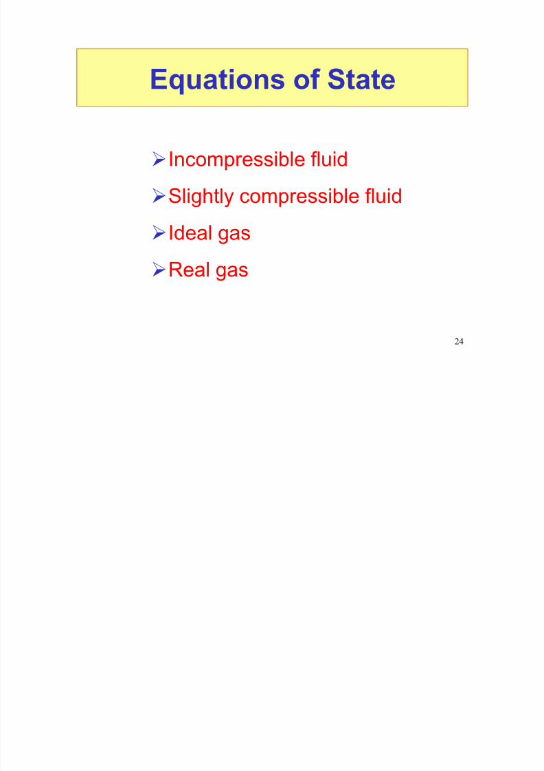
Equations of State
Incompressible fluid
Slightly compressible fluid
Ideal gas
Real gas

8/18/2019 Drill Hydraulics
http://slidepdf.com/reader/full/drill-hydraulics 25/39

8/18/2019 Drill Hydraulics
http://slidepdf.com/reader/full/drill-hydraulics 26/39
26

8/18/2019 Drill Hydraulics
http://slidepdf.com/reader/full/drill-hydraulics 27/39
27
Law of Conservation of Energy
States that as a fluid flowsfrom point 1 to point 2:
QW
vv D D g
V pV p E E
2
1
2
212
112212
2
1
In the wellbore, in many cases Q = 0 (heat) = constant{

8/18/2019 Drill Hydraulics
http://slidepdf.com/reader/full/drill-hydraulics 28/39
28
In practical field units this equation simplifies to:
f p p P vv
D D p p
21
22
4
1212
10*074.8
052.0
p 1 and p 2 are pressures in psi is density in lbm/gal.v 1 and v 2 are velocities in ft/sec. p p is pressure added by pump
between points 1 and 2 in psi p f is frictional pressure loss in psi
D1 and D2 are depths in ft.
where

8/18/2019 Drill Hydraulics
http://slidepdf.com/reader/full/drill-hydraulics 29/39
29
Determine the pressure at thebottom of the drill collars, if
psi 000,3 pin. 5.2
0 D
ft. 000,10 D
lbm/gal. 12
gal/min. 400 q
psi 1,400
p
1
2
DC
f
ID
p
(bottom of drill collars)
(mud pits)

8/18/2019 Drill Hydraulics
http://slidepdf.com/reader/full/drill-hydraulics 30/39
30
Velocity in drill collars
)(in
(gal/min) d448.2
qv 222
ft/se14.26)5.2(*448.2
400v 22
Velocity in mud pits, v 1 0

8/18/2019 Drill Hydraulics
http://slidepdf.com/reader/full/drill-hydraulics 31/39
31
400,1000,36.6240,60
400,1000,3)014.26(12*10*8.074-
0)-(10,00012*052.00p
PP)vv(10*074.8
)DD(052.0pp
224-
2
f p21
22
4-
1212
Pressure at bottom of drill collars = 7,833 psig
NOTE: KE in collars
May be ignored in many cases
0

8/18/2019 Drill Hydraulics
http://slidepdf.com/reader/full/drill-hydraulics 32/39
32
f p P P vv D D p p
)(10*074.8 )(052.0
21
22
4-
1212

8/18/2019 Drill Hydraulics
http://slidepdf.com/reader/full/drill-hydraulics 33/39

8/18/2019 Drill Hydraulics
http://slidepdf.com/reader/full/drill-hydraulics 34/39
34
If
95.0c 10*074.8
pcv
as writtenbemayEquation
d4dn
0 f P
This accounts for all the losses in the nozzle.
Example: ft/sec 30512*10*074.8
000,195.0v 4n

8/18/2019 Drill Hydraulics
http://slidepdf.com/reader/full/drill-hydraulics 35/39
35

8/18/2019 Drill Hydraulics
http://slidepdf.com/reader/full/drill-hydraulics 36/39
36
For multiple nozzles in //
Vn is the same for each nozzleeven if the d n varies!
This follows since p is the same across each nozzle.
tn A117.3
qv
2t
2d
2-5
bit AC
q10*8.311 Δp
10*074.8
pcv 4dn &

8/18/2019 Drill Hydraulics
http://slidepdf.com/reader/full/drill-hydraulics 37/39
8/18/2019 Drill Hydraulics
http://slidepdf.com/reader/full/drill-hydraulics 38/39
38
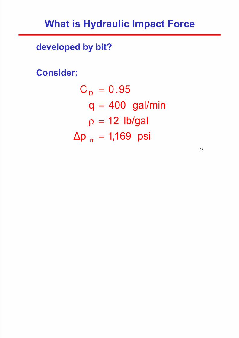
What is Hydraulic Impact Force
developed by bit?
Consider:
psi169,1 Δplb/gal12
gal/min400q
95.0C
n
D
8/18/2019 Drill Hydraulics
http://slidepdf.com/reader/full/drill-hydraulics 39/39
39
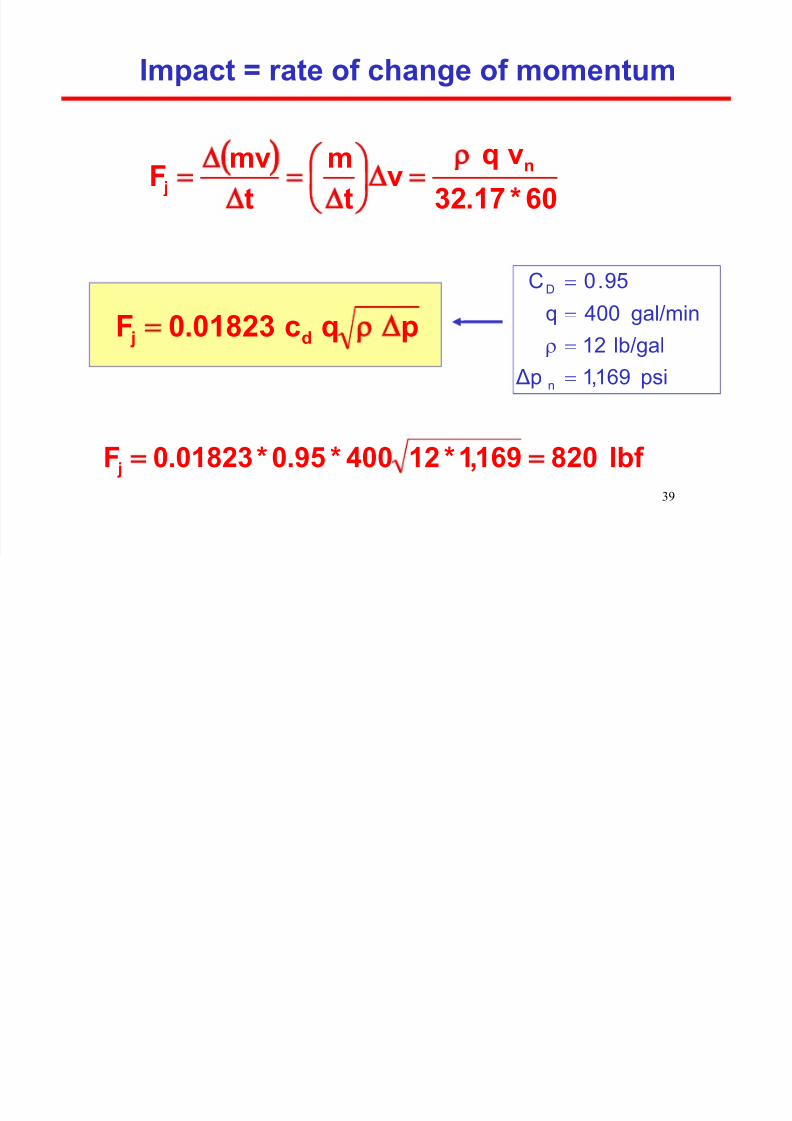
Impact = rate of change of momentum
60*17.32
vqv
tm
tmv
F n j
psi169,1 Δplb/gal12
gal/min400q95.0C
n
D
lbf 820169,1*12400*95.0*01823.0F j
pqc01823.0F d j