drexelbrook - escventura.com
TRANSCRIPT

Series CM3Cut Monitor
with HART® Protocolusing 409-1000 Electronics
The Leader of RFand Sonic Level
Installation andOperating Instructions
DREXELBROOK
Able Instruments & Controls Limited. Cutbush Park, Danehill, Lower Earley, Reading. Berkshire. RG6 4UT. UK.Tel: +44 (0) 118 9311188 Fax: +44 (0) 118 9312161 Email: [email protected] Web: www.able.co.uk Buy Online: www.247able.com

AMETEK Drexelbrook makes no warranty of any kind with regard to the material containedin this manual, including, but not limited to, implied warranties or fitness for a particularpurpose. Drexelbrook shall not be liable for errors contained herein or for incidental orconsequential damages in connection with the performance or use of material.
Copyright 2000 AMETEK Drexelbrook

EDO#2-99-255509-0277-LM
Series CM3Cut Monitor
with HART® Protocolusing 409-1000 Electronics
205 Keith Valley Road Horsham, PA 19044US Sales 800-553-9092 24 Hour Service 800-527-6297International 215-674-1234Fax 215-674-2731E-mail [email protected] www.drexelbrook.comAn ISO 9001 Certified Company
DREXELBROOK
EDO#2-99-255509-0277-LM
Table of Contents
SECTION 1 INTRODUCTION .......................................................................................... 11.1 Description ................................................................................................................. 11.2 Models Available ....................................................................................................... 1
SECTION 2 INSTALLATION......................................................................................... 52.1 Unpacking .................................................................................................................. 52.2 Mounting the Electronic Unit................................................................................... 52.3 Mounting the Sensing Element .............................................................................. 102.4 Wiring the Electronic Unit ..................................................................................... 132.5 Wiring the Sensing Element (Remote Electronic Units) ...................................... 152.6 Surge Voltage (Lightning Protection) .................................................................... 162.7 RFI (Radio Frequency Interference) ...................................................................... 16
SECTION 3 OPERATION ............................................................................................. 183.1 General Description ................................................................................................ 183.2 PC Software Model Number ................................................................................... 183.3 PC Software Specifications ..................................................................................... 193.4 Installing the Modem .............................................................................................. 193.5 Installing the Software on the Hard Drive ............................................................ 20
3.5.1 Running PC Software from the Hard Drive as a DOS Program ............... 203.5.2 Running PC Software from the Hard Drive in Windows 95®................... 21
3.6 Description of the Function Keys ........................................................................... 223.7 Using the PC Software Menu ................................................................................. 24
SECTION 4 CALIBRATION ......................................................................................... 254.1 Checking Calibration Data ..................................................................................... 254.2 Trimming Factory Calibration ............................................................................... 264.3 Recalibration............................................................................................................ 27
SECTION 5 SERVICE.................................................................................................... 285.1 Telephone Assistance .............................................................................................. 285.2 Equipment Return................................................................................................... 285.3 Field Service ............................................................................................................ 295.4 Customer Training .................................................................................................. 29
SECTION 6 SPECIFICATIONS ................................................................................... 306.1 Specifications for the Electronic Unit .................................................................... 306.2 Specifications for Coaxial Cable ............................................................................. 31
CM3 Series Cut Monitor with Universal III TransmitterTM
1
The instructions in this manual are for the DrexelbrookCM3 Series Cut Monitor used for measurement of water-in-oil (B.S.&W.) applications.
Each Drexelbrook CM3 Cut Monitor consists of aUniversal IIITM (409-1000) series two-wire, 4-20 mA elec-tronic unit and a 700 series sensing element (probe). A380 series connecting cable is also supplied when thesensing element is mounted remotely from the electronicunit.
The CM3 Cut Monitor is a smart capacitance-to-currentdevice. A change in oil composition produces a capaci-tance change that results in a change of signal current.
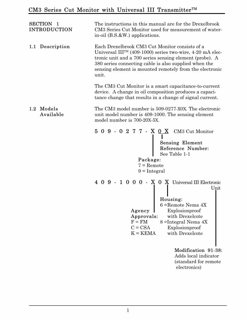
The CM3 model number is 509-0277-X0X. The electronicunit model number is 409-1000. The sensing elementmodel number is 700-20X-5X.
5 0 9 - 0 2 7 7 - X 0 X CM3 Cut Monitor
Sensing ElementReference Number:See Table 1-1
Package:7 = Remote9 = Integral
4 0 9 - 1 0 0 0 - X 0 X Universal III ElectronicUnit
Housing:6 =Remote Nema 4X
Agency ExplosionproofApprovals: with DrexelcoteF = FM 8 =Integral Nema 4XC = CSA ExplosionproofK = KEMA with Drexelcote
Modification 91-38:Adds local indicator(standard for remote electronics)
SECTION 1INTRODUCTION
1.1 Description
1.2 ModelsAvailable
CM3 Series Cut Monitor with Universal IIITM Transmitter
2
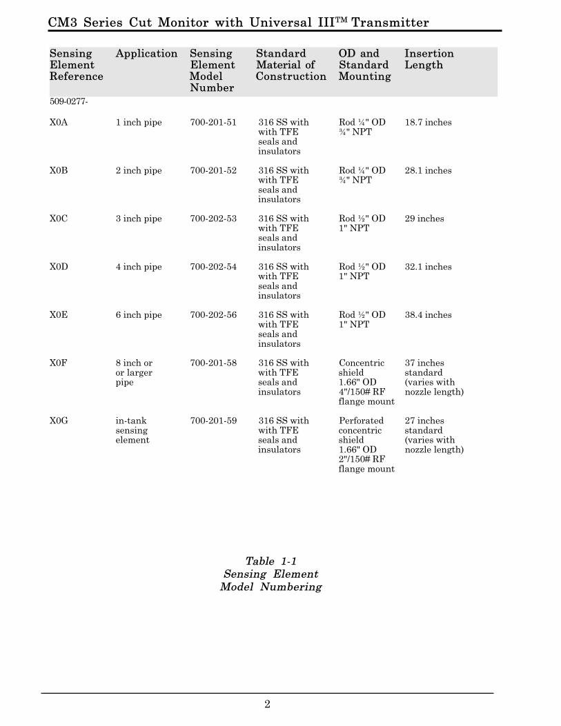
Sensing Application Sensing Standard OD and InsertionElement Element Material of Standard LengthReference Model Construction Mounting
Number509-0277-
X0A 1 inch pipe 700-201-51 316 SS with Rod ¼" OD 18.7 incheswith TFE ¾" NPTseals andinsulators
X0B 2 inch pipe 700-201-52 316 SS with Rod ¼" OD 28.1 incheswith TFE ¾" NPTseals andinsulators
X0C 3 inch pipe 700-202-53 316 SS with Rod ½" OD 29 incheswith TFE 1" NPTseals andinsulators
X0D 4 inch pipe 700-202-54 316 SS with Rod ½" OD 32.1 incheswith TFE 1" NPTseals andinsulators
X0E 6 inch pipe 700-202-56 316 SS with Rod ½" OD 38.4 incheswith TFE 1" NPTseals andinsulators
X0F 8 inch or 700-201-58 316 SS with Concentric 37 inchesor larger with TFE shield standardpipe seals and 1.66" OD (varies with
insulators 4"/150# RF nozzle length)flange mount
X0G in-tank 700-201-59 316 SS with Perforated 27 inchessensing with TFE concentric standardelement seals and shield (varies with
insulators 1.66" OD nozzle length)2"/150# RFflange mount
Table 1-1Sensing Element
Model Numbering
CM3 Series Cut Monitor with Universal III TransmitterTM
3
The standard electronic unit (409-1000-X0X) is mountedin an explosionproof housing that meets the followingclassifications:
•NEMA 4X Waterproof/Corrosion Resistant.
•NEMA 7 Explosionproof FM Approved for:Class I Gr. A,B,C & D;Class II Gr. E, F, & G;Class III.
The remote electronic unit and sensing element are con-nected by a three-terminal coaxial cable (380-0xx-12).
•The xx in the model number indicates the length of the cable in feet.•Maximum length is 25 feet.•Shorter lengths are available.•Cable can also be purchased in bulk lengths with
termination kits.
1.2 ModelsAvailable(cont.)
CM3 Series Cut Monitor with Universal IIITM Transmitter
4
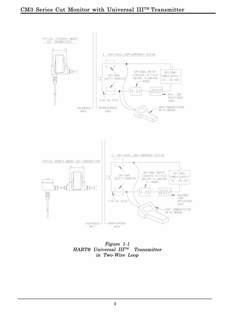
Figure 1-1HART® Universal IIITM Transmitter
in Two-Wire Loop

CM3 Series Cut Monitor with Universal III TransmitterTM
5
Carefully remove the contents of the carton and checkeach item against the packing list before destroying anypacking material. If there is any shortage or damage,report it immediately to the factory.
The integral electronic unit is mounted with the sensingelement. The remote electronic unit is designed for fieldmounting, but it should be mounted in a location as freeas possible from vibration, corrosive atmospheres, andany possibility of mechanical damage. For convenience atstart-up, mount the instrument in a reasonably accessiblelocation. Ambient temperatures should be between -40°Fand 185°F (-40°C and 85°C).
NOTEWhen installing conduit to the electronicunit, be sure that vertical conduit runs willnot cause water to enter the electronic unithousing, as shown in Figure 2-1.
Figure 2-1 shows the recommended conduit installation.See Figures 2-2 through 2-5 for mounting dimensions.
Figure 2-1Recommended Conduit Connection
SECTION 2INSTALLATION
2.1 Unpacking
2.2 Mounting theElectronic Unit
RECOMMENDED
ConduitBreather
Drain
DREXELBROOK
All Connectionssealed and gaskets
in place
DREXELBROOK
Condensation canenter Housing
NOTRECOMMENDED

CM3 Series Cut Monitor with Universal IIITM Transmitter
6
Figure 2-2Mounting DimensionsIntegral Electronics
1" through 6" Pipe Size

CM3 Series Cut Monitor with Universal III TransmitterTM
7
Figure 2-3Mounting DimensionsIntegral Electronics
Greater than 8" Pipe Size
CM3 Series Cut Monitor with Universal IIITM Transmitter
8
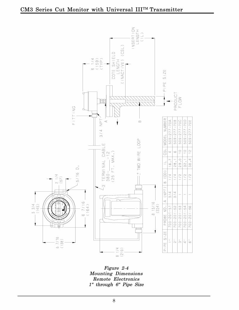
Figure 2-4Mounting Dimensions
Remote Electronics1" through 6" Pipe Size
CM3 Series Cut Monitor with Universal III TransmitterTM
9
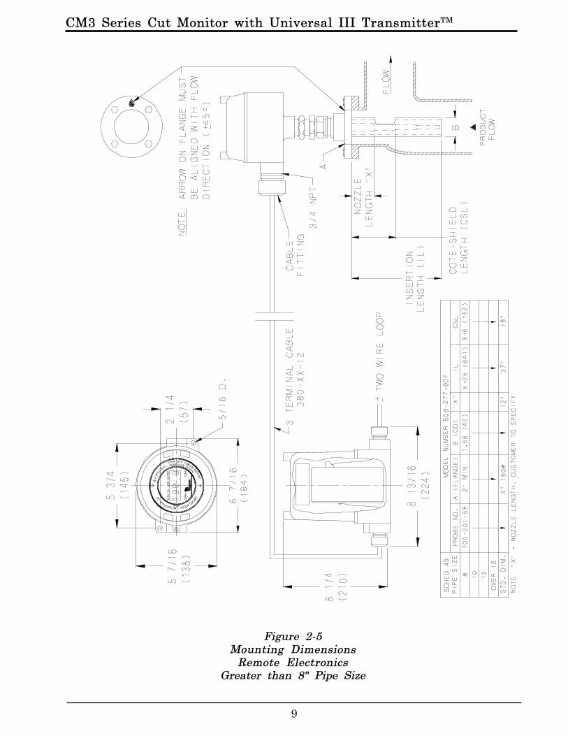
Figure 2-5Mounting Dimensions
Remote ElectronicsGreater than 8" Pipe Size
CM3 Series Cut Monitor with Universal IIITM Transmitter
10
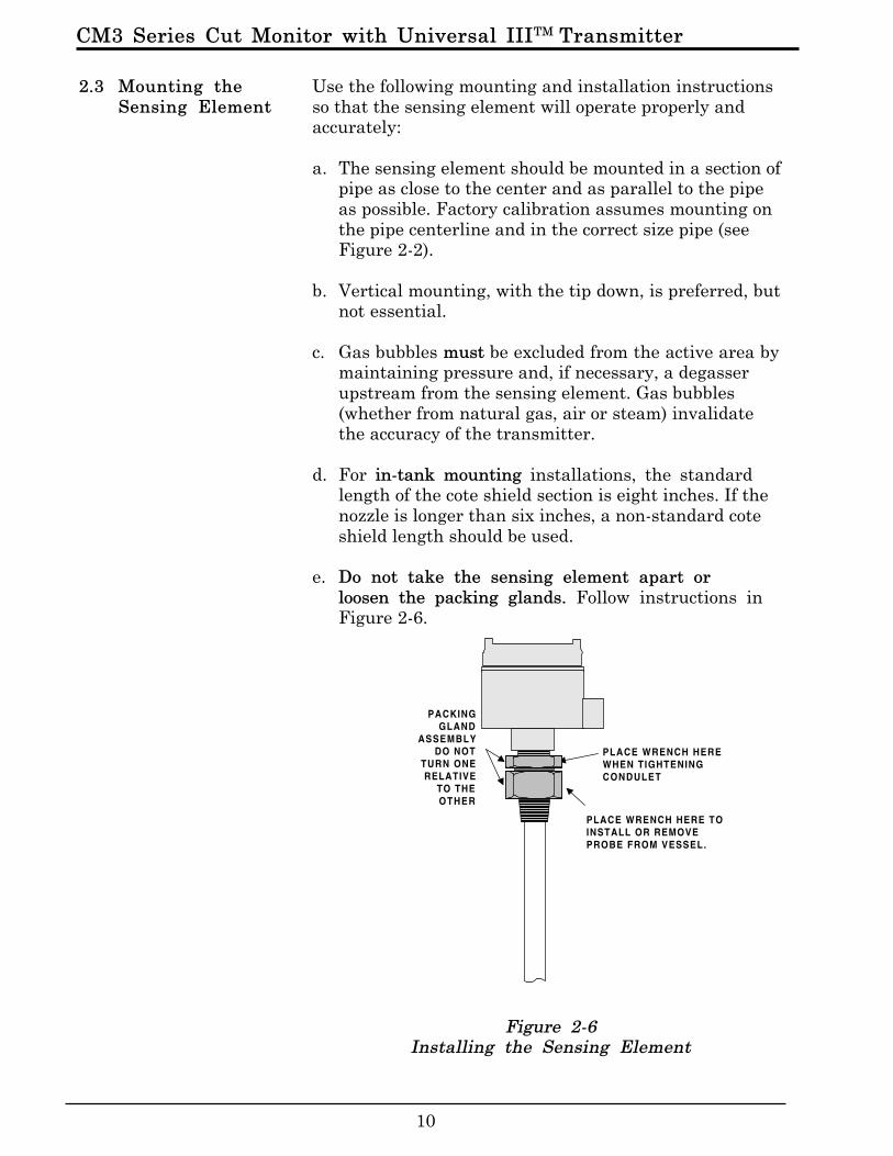
Use the following mounting and installation instructionsso that the sensing element will operate properly andaccurately:
a. The sensing element should be mounted in a section ofpipe as close to the center and as parallel to the pipeas possible. Factory calibration assumes mounting onthe pipe centerline and in the correct size pipe (seeFigure 2-2).
b. Vertical mounting, with the tip down, is preferred, butnot essential.
c. Gas bubbles must be excluded from the active area bymaintaining pressure and, if necessary, a degasserupstream from the sensing element. Gas bubbles(whether from natural gas, air or steam) invalidatethe accuracy of the transmitter.
d. For in-tank mounting installations, the standardlength of the cote shield section is eight inches. If thenozzle is longer than six inches, a non-standard coteshield length should be used.
e. Do not take the sensing element apart orloosen the packing glands. Follow instructions inFigure 2-6.
Figure 2-6Installing the Sensing Element
CONDULET
PLACE WRENCH HERE TOINSTALL OR REMOVEPROBE FROM VESSEL.
PACKINGGLAND
ASSEMBLYDO NOT
TURN ONERELATIVE
TO THEOTHER
PLACE WRENCH HEREWHEN TIGHTENINGCONDULET
2.3 Mounting theSensing Element
CM3 Series Cut Monitor with Universal III TransmitterTM
11
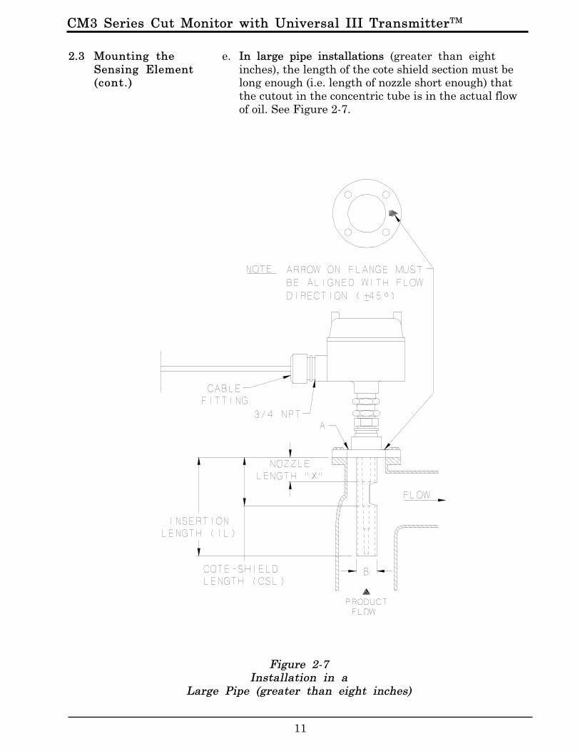
2.3 Mounting theSensing Element(cont.)
e. In large pipe installations (greater than eightinches), the length of the cote shield section must belong enough (i.e. length of nozzle short enough) thatthe cutout in the concentric tube is in the actual flowof oil. See Figure 2-7.
Figure 2-7Installation in a
Large Pipe (greater than eight inches)

CM3 Series Cut Monitor with Universal IIITM Transmitter
12
Figure 2-8Installation in a Pipe 18 inches or larger
f. For large pipes with no bends (18 inch and larger), it ispossible to mount the sensing element at a 45 degreeangle to provide sufficient flow through the shield ofthe sensing element. See Figure 2-8.
2.3 Mounting theSensing Element(cont.)
CM3 Series Cut Monitor with Universal III TransmitterTM
13
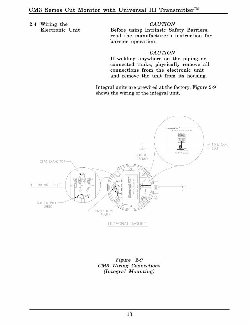
CAUTIONBefore using Intrinsic Safety Barriers,read the manufacturer's instruction forbarrier operation.
CAUTIONIf welding anywhere on the piping orconnected tanks, physically remove allconnections from the electronic unitand remove the unit from its housing.
Integral units are prewired at the factory. Figure 2-9shows the wiring of the integral unit.
2.4 Wiring theElectronic Unit
Figure 2-9CM3 Wiring Connections
(Integral Mounting)
CM3 Series Cut Monitor with Universal IIITM Transmitter
14
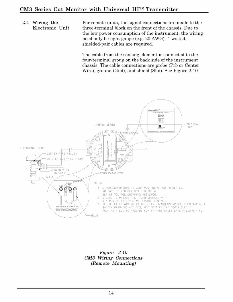
2.4 Wiring theElectronic Unit
Figure 2-10CM3 Wiring Connections
(Remote Mounting)
For remote units, the signal connections are made to thethree-terminal block on the front of the chassis. Due tothe low power consumption of the instrument, the wiringneed only be light gauge (e.g. 20 AWG). Twisted,shielded-pair cables are required.
The cable from the sensing element is connected to thefour-terminal group on the back side of the instrumentchassis. The cable connections are probe (Prb or CenterWire), ground (Gnd), and shield (Shd). See Figure 2-10
CM3 Series Cut Monitor with Universal III TransmitterTM
15
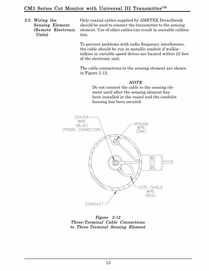
2.5 Wiring theSensing Element(Remote Electronic Units)
Figure 2-12Three-Terminal Cable Connectionsto Three-Terminal Sensing Element
Only coaxial cables supplied by AMETEK Drexelbrookshould be used to connect the transmitter to the sensingelement. Use of other cables can result in unstable calibra-tion.
To prevent problems with radio frequency interference,the cable should be run in metallic conduit if walkie-talkies or variable speed drives are located within 25 feetof the electronic unit.
The cable connections to the sensing element are shownin Figure 2-12.
NOTEDo not connect the cable to the sensing ele-ment until after the sensing element hasbeen installed in the vessel and the condulethousing has been secured.
CM3 Series Cut Monitor with Universal IIITM Transmitter
16
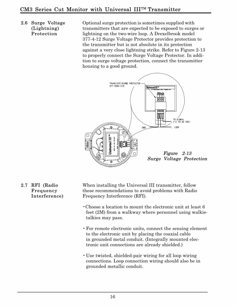
Optional surge protection is sometimes supplied withtransmitters that are expected to be exposed to surges orlightning on the two-wire loop. A Drexelbrook model377-4-12 Surge Voltage Protector provides protection tothe transmitter but is not absolute in its protectionagainst a very close lightning strike. Refer to Figure 2-13to properly connect the Surge Voltage Protector. In addi-tion to surge voltage protection, connect the transmitterhousing to a good ground.
When installing the Universal III transmitter, followthese recommendations to avoid problems with RadioFrequency Interference (RFI).
•Choose a location to mount the electronic unit at least 6feet (2M) from a walkway where personnel using walkie-talkies may pass.
• For remote electronic units, connect the sensing elementto the electronic unit by placing the coaxial cablein grounded metal conduit. (Integrally mounted elec-tronic unit connections are already shielded.)
• Use twisted, shielded-pair wiring for all loop wiringconnections. Loop connection wiring should also be ingrounded metallic conduit.
2.6 Surge Voltage(Lightning)Protection
2.7 RFI (RadioFrequencyInterference)
Figure 2-13Surge Voltage Protection

CM3 Series Cut Monitor with Universal III TransmitterTM
17
2.7 RFI (RadioFrequencyInterference)(cont.)
• Do not run power wiring in the same conduit with signalcables
• Ground the electronic unit and housing with a minimumof 14 gauge wire to a good earth ground. Make sure thatconduits entering and leaving the housing have a goodelectrical ground connection to the housing.
The RFI recommendations listed above provide a degreeof protection that is usually sufficient to protect againstwalkie-talkies used 3 feet (1M) or more from a typicalelectronic unit.
CM3 Series Cut Monitor with Universal IIITM Transmitter
18
This section instructs the user how to use the Drexelbrook401-700-20 Series PC software to calibrate the UniversalIII transmitter.
The 401-700-20 software package allows the use of anyDOS or Windows-based personal computer to interfacewith the CM3 HART protocol transmitter.
A PC and Drexelbrook software can be used in place ofthe Rosemount handheld calibrator used for multi-PVtransmitters.
4 0 1 - 0 7 0 0 - 0 2 X
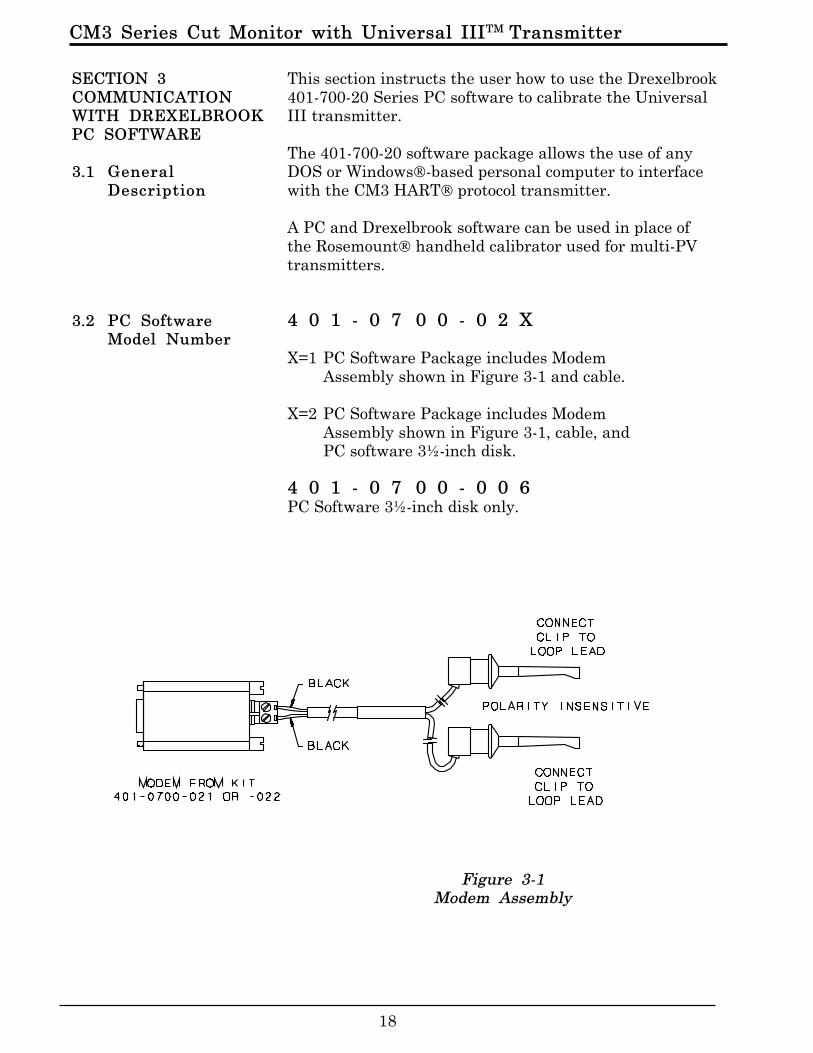
X=1 PC Software Package includes ModemAssembly shown in Figure 3-1 and cable.
X=2 PC Software Package includes ModemAssembly shown in Figure 3-1, cable, andPC software 3½-inch disk.
4 0 1 - 0 7 0 0 - 0 0 6PC Software 3½-inch disk only.
Figure 3-1Modem Assembly
SECTION 3COMMUNICATIONWITH DREXELBROOKPC SOFTWARE
3.1 GeneralDescription
3.2 PC SoftwareModel Number
CM3 Series Cut Monitor with Universal III TransmitterTM
19
—PC Requirements8088 DOS-based PC or higher using DOS version 3.1 orhigher. While it is possible to operate from the 1.44 mega-byte floppy disk furnished with the 401-700-20 package, itis recommended that the software be installed on a harddrive with 0.5 megabytes or more of space available.
—Input to ModemRS232 from the COM1 serial port. The PC provides oper-ating power for the modem but not for the transmitter.
—Cable (included with Modem)5-foot modem to transmitter loop connection
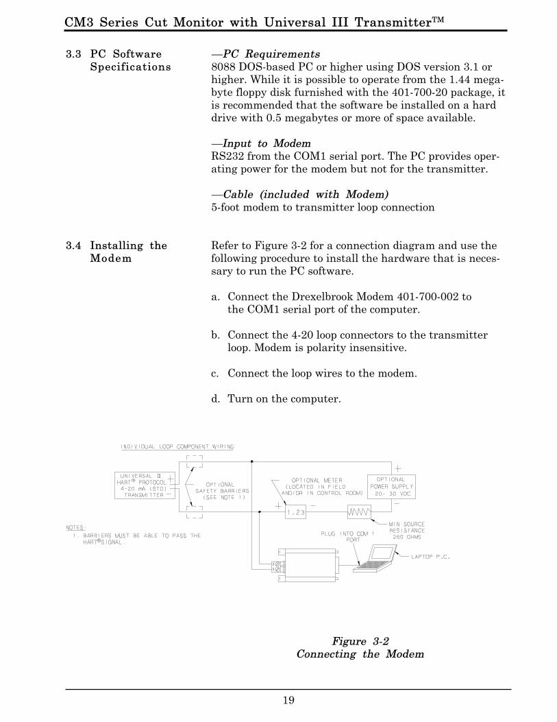
Refer to Figure 3-2 for a connection diagram and use thefollowing procedure to install the hardware that is neces-sary to run the PC software.
a. Connect the Drexelbrook Modem 401-700-002 tothe COM1 serial port of the computer.
b. Connect the 4-20 loop connectors to the transmitterloop. Modem is polarity insensitive.
c. Connect the loop wires to the modem.
d. Turn on the computer.
Figure 3-2Connecting the Modem
3.3 PC SoftwareSpecifications
3.4 Installing theModem

CM3 Series Cut Monitor with Universal IIITM Transmitter
20
NOTEWhile it is possible to operate from the 1.44 mega-byte floppy disk furnished with the 401-700-20package, it is recommended that the software beinstalled on a hard drive with 0.5 megabytes ormore of space available.
NOTEThe PC software is a DOS-based program. Itcannot be installed directly from Windows 3.1 orWindows 95.
a. If you are using Windows, go to the MS DOSprompt to install the PC software.
b. Place the 401-700-006 software disk into thedrive (usually drive a:).
c. At the c:> prompt, type a: install. The programwill create a directory on the hard drive calledHART60 and place the program file there.
d. At this point, the software is loaded onto the harddrive, you can:•run the software from the DOS mode, or•create a program icon (or shortcut) and run the software in Windows.
To run the PC software from DOS:
a. Type cd:\HART60
b. Type HART60
3.5 Installing theSoftware on theHard Drive
3.5.1 Running PCSoftware from theHard Drive as aDOS Program
CM3 Series Cut Monitor with Universal III TransmitterTM
21
To run the PC software from Windows 95:
a. Click the Start button, and then point to Settings.
b. Click Taskbar, and then click the Start MenuPrograms tab.
c. Click Add and type c:\hart60\hart60.exe
d. Click Next, and then double-click the Programsmenu where Hart60 is to appear.
e. Choose a name and icon and then click Finish andOK.
Steps a. through e. should have placed the DE LOGO iconin the Programs menu.
f. Double click on the DE LOGO icon and the HARTprogram should run under a window.
g. The software starts communicating with the HARTprotocol transmitter and returns with Tag ID andall existing configuration information. Press F1 atany time for on-line Help.
NOTEOn new units the Tag ID is preset by thefactory to the unit’s serial number.
h. Press F3 to read the HART Protocol transmitter’spresent database. It takes several seconds to uploadthe information in the transmitter. When the upload iscomplete, the screen shows the transmitter’s data-base parameters.
3.5.2 Running PCSoftware from theHard Drive inWindows 95
CM3 Series Cut Monitor with Universal IIITM Transmitter
22
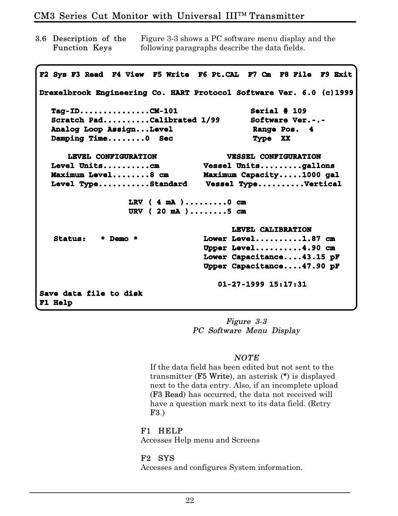
Figure 3-3 shows a PC software menu display and thefollowing paragraphs describe the data fields.
Figure 3-3PC Software Menu Display
NOTEIf the data field has been edited but not sent to thetransmitter (F5 Write), an asterisk (*) is displayednext to the data entry. Also, if an incomplete upload(F3 Read) has occurred, the data not received willhave a question mark next to its data field. (RetryF3.)
F1 HELPAccesses Help menu and Screens
F2 SYSAccesses and configures System information.
3.6 Description of theFunction Keys
F2 Sys F3 Read F4 View F5 Write F6 Pt.CAL F7 Cm F8 File F9 ExitF2 Sys F3 Read F4 View F5 Write F6 Pt.CAL F7 Cm F8 File F9 ExitF2 Sys F3 Read F4 View F5 Write F6 Pt.CAL F7 Cm F8 File F9 ExitF2 Sys F3 Read F4 View F5 Write F6 Pt.CAL F7 Cm F8 File F9 ExitF2 Sys F3 Read F4 View F5 Write F6 Pt.CAL F7 Cm F8 File F9 Exit
Drexelbrook Engineering Co. HART Protocol Software Ver. 6.0 (c)1999Drexelbrook Engineering Co. HART Protocol Software Ver. 6.0 (c)1999Drexelbrook Engineering Co. HART Protocol Software Ver. 6.0 (c)1999Drexelbrook Engineering Co. HART Protocol Software Ver. 6.0 (c)1999Drexelbrook Engineering Co. HART Protocol Software Ver. 6.0 (c)1999
Tag-ID...............CM-101Tag-ID...............CM-101Tag-ID...............CM-101Tag-ID...............CM-101Tag-ID...............CM-101 Serial # 109Serial # 109Serial # 109Serial # 109Serial # 109Scratch Pad..........Calibrated 1/99Scratch Pad..........Calibrated 1/99Scratch Pad..........Calibrated 1/99Scratch Pad..........Calibrated 1/99Scratch Pad..........Calibrated 1/99 Software Ver.-.-Software Ver.-.-Software Ver.-.-Software Ver.-.-Software Ver.-.-Analog Loop Assign...Level Range Pos. 4Analog Loop Assign...Level Range Pos. 4Analog Loop Assign...Level Range Pos. 4Analog Loop Assign...Level Range Pos. 4Analog Loop Assign...Level Range Pos. 4Damping Time........0 Sec Type XXDamping Time........0 Sec Type XXDamping Time........0 Sec Type XXDamping Time........0 Sec Type XXDamping Time........0 Sec Type XX
LEVEL CONFIGURATION VESSEL CONFIGURATION LEVEL CONFIGURATION VESSEL CONFIGURATION LEVEL CONFIGURATION VESSEL CONFIGURATION LEVEL CONFIGURATION VESSEL CONFIGURATION LEVEL CONFIGURATION VESSEL CONFIGURATIONLevel Units..........cmLevel Units..........cmLevel Units..........cmLevel Units..........cmLevel Units..........cm Vessel Units.........gallonsVessel Units.........gallonsVessel Units.........gallonsVessel Units.........gallonsVessel Units.........gallonsMaximum Level........8 cmMaximum Level........8 cmMaximum Level........8 cmMaximum Level........8 cmMaximum Level........8 cm Maximum Capacity.....1000 galMaximum Capacity.....1000 galMaximum Capacity.....1000 galMaximum Capacity.....1000 galMaximum Capacity.....1000 galLevel Type...........Standard Vessel Type..........VerticalLevel Type...........Standard Vessel Type..........VerticalLevel Type...........Standard Vessel Type..........VerticalLevel Type...........Standard Vessel Type..........VerticalLevel Type...........Standard Vessel Type..........Vertical
LRV ( 4 mA ).........0 cm LRV ( 4 mA ).........0 cm LRV ( 4 mA ).........0 cm LRV ( 4 mA ).........0 cm LRV ( 4 mA ).........0 cm URV ( 20 mA )........5 cm URV ( 20 mA )........5 cm URV ( 20 mA )........5 cm URV ( 20 mA )........5 cm URV ( 20 mA )........5 cm
LEVEL CALIBRATION LEVEL CALIBRATION LEVEL CALIBRATION LEVEL CALIBRATION LEVEL CALIBRATION Status: * Demo * Status: * Demo * Status: * Demo * Status: * Demo * Status: * Demo * Lower Level..........1.87 cmLower Level..........1.87 cmLower Level..........1.87 cmLower Level..........1.87 cmLower Level..........1.87 cm
Upper Level..........4.90 cmUpper Level..........4.90 cmUpper Level..........4.90 cmUpper Level..........4.90 cmUpper Level..........4.90 cmLower Capacitance....43.15 pFLower Capacitance....43.15 pFLower Capacitance....43.15 pFLower Capacitance....43.15 pFLower Capacitance....43.15 pFUpper Capacitance....47.90 pFUpper Capacitance....47.90 pFUpper Capacitance....47.90 pFUpper Capacitance....47.90 pFUpper Capacitance....47.90 pF
01-27-1999 15:17:31 01-27-1999 15:17:31 01-27-1999 15:17:31 01-27-1999 15:17:31 01-27-1999 15:17:31Save data file to diskSave data file to diskSave data file to diskSave data file to diskSave data file to diskF1 HelpF1 HelpF1 HelpF1 HelpF1 Help

CM3 Series Cut Monitor with Universal III TransmitterTM
23
Service: Access toll-free service phone number.Print: Print configuration screen.Other items are not applicable.
F3 READ (receive transmitter data)Reads all pertinent data from the transmitter and dis-plays it on the screen. The Tag-ID is displayed in thecommunication window. Once the tag is read and a validHART protocol transmitter is detected, you may use theESC key to abort the interrogation if this is not the cor-rect transmitter loop. However, if an incomplete uploadhas occurred, the data not received will have a questionmark (?) next to its data field. The READ function alsoupdates the real-time window level, vessel, capacitance,current and status after completing loading the data.
F4 VIEW (monitor transmitter data)Displays the real-time values of cut, sensor capacitance inpF, loop current, and percent of range from the UniversalIII transmitter. If the transmitter status is anythingother than OK, a detailed status message is displayed.Use the ESC key to abort the PV update.
F5 WRITE (send data to transmitter)Sends new or edited configuration data to the transmitter.Data that has been edited but not sent to the transmitterhas an asterisk next to its data field.
F6 PT. CAL (point calibration)Calibrates the Universal III transmitter using Pointcalibration with two actual composition points. The highand low water percentage must be known.
F7 CMSelects the Communication Port: COM1.
F8 FILEThis function loads or saves the data on the screen to aPC disk file with an .SLT and .TXT file extension.
F9 EXITExit PC software.
3.6 Description of theFunction Keys(cont.)
CM3 Series Cut Monitor with Universal IIITM Transmitter
24
All Drexelbrook CM3 Series Cut Monitor instruments areconfigured and calibrated at the factory.
Two of the data fields in the menu can be changed toidentify the instrument specifically for the application. Tomake an entry in these data fields, position the cursor andtype over the existing entry.
• Use Tag IDTag IDTag IDTag IDTag ID (8 characters) to identify the unit or vessel.
• Use the ScratchpadScratchpadScratchpadScratchpadScratchpad (32 characters) to record the dateof calibration or other similar notes.
Press F5 WriteF5 WriteF5 WriteF5 WriteF5 Write.
Other data fields on the menu relate to the cut monitormeasurement. These data fields should not be changedunless instructed by a factory service engineer.
•The Analog Loop AssignAnalog Loop AssignAnalog Loop AssignAnalog Loop AssignAnalog Loop Assignment is made at the factoryaccording to the desired range set by the coarse spanjumper on the side of the electronic unit. The jumper isset at the factory. Do not change the factory setting.
• For a cut monitor application, Level Units Level Units Level Units Level Units Level Units data fieldrepresents % Water Units, measured in cmcmcmcmcm (cut measure-ment).
•Maximum LevelMaximum LevelMaximum LevelMaximum LevelMaximum Level is factory set to coincide with the rangeset by the coarse span jumper. Do not change thefactory setting.
• For a cut monitor application, the LRVLRVLRVLRVLRV (4 mA) corre-sponds to dry oil or 0% water (0.00 cm).
• For a cut monitor application, the URVURVURVURVURV corresponds tothe full scale water percentage (e.g. 10.00 cm on the 10%water range).
3.7 Using the PCSoftware Menu
CM3 Series Cut Monitor with Universal III TransmitterTM
25
All Drexelbrook CM3 Series Cut Monitor instruments arecalibrated at the factory according to:
•size of pipe, and•density of oil specified.
Specific factors could cause the factory calibration to beless accurate than is required. For example,
a. Pipe I.D. is smaller than nominal size (Sched. 80,160, or extra heavy pipe)
b. Sensing element is not centered (parallel to axis) inpipe. This condition causes higher (never lower)readings.
c. Oil may be heavier (higher readings) or lighter(lower readings) than expected.
d. Major temperature deviations.
Do not change the factory calibration without obtain-ing data that indicates a calibration change is necessary.
If the output reading is low because of gas, steam, or airin the stream, then no amount of calibration will producesatisfactory performance. Eliminate the gas problem, orconsult the factory at 1-800-527-6297. Once the gas isgone, a legitimate calibration check can be made.
The following equipment is required to check the calibra-tion of a cut monitor application and record sample data:
•A centrifuge (or other API-approved standard) to sample BS&W content.
•If the stream temperature is greater than 150ºF (65ºC), a sampling bomb with a minimum capacity of 500 ml.
•Temperature stabilization bath.
SECTION 4CALIBRATION
4.1 CheckingCalibrationData
CM3 Series Cut Monitor with Universal IIITM Transmitter
26
To record the sample, proceed as follows:
a. With a personal computer connected to the loop, (asdetailed in section 3.3), use key F4 to displayReal-time View. As sample is taken, record the
•output value (cm) and•capacitance value (pF).
Generally, these two values should be recorded at oneor more different levels of water content (wetter ordryer).
b. If stream temperature is greater than 150ºF (65ºC),use the sampling bomb to take the sample andstabilize the temperature at 150ºF before attempt-ing to spin the sample in the centrifuge.
Compare spin results to the output readings to determineif calibration needs to be trimmed.
•If the deviation is less than 1.5% water, proceed to section 4.2 Trimming Calibration.•If the deviation is greater than 1.5% water, proceed to section 4.3 Recalibration.
Use the following procedure to trim (fine tune) the factorycalibration.
a. On the Menu display of the PC software, move thecursor to the LEVEL CALIBRATIONLEVEL CALIBRATIONLEVEL CALIBRATIONLEVEL CALIBRATIONLEVEL CALIBRATION submenu.
b. Enter the deviation amount plus the present real-time value for Lower LevelLower LevelLower LevelLower LevelLower Level (zero calibrationvalue). Press Enter.
For example, if the sampled output was .85% lowerthan the spin reading; and the present real-timevalue is 1.02 cm; enter 1.87 cm for Lower LevelLower LevelLower LevelLower LevelLower Level.
c. Enter the deviation amount plus the present real-time value for Upper LevelUpper LevelUpper LevelUpper LevelUpper Level (fullscale calibrationvalue). Press Enter.
Using the same example, if the present real-timevalue is 10.05 cm; enter 10.90 cm for Upper LevelUpper LevelUpper LevelUpper LevelUpper Level.
4.1 CheckingCalibrationData (cont.)
4.2 TrimmingFactoryCalibration

CM3 Series Cut Monitor with Universal III TransmitterTM
27
If the sample data recorded in section 4.1 Checking theCalibration Data, has a deviation greater than 1.5%water:
a. Record sample data and obtain the deviations atthe high and low ends of the range--at least half ofthe span apart.
For example, on a 0-1% range, the readings shoulddiffer by at least 0.50 cm. On a 0-50% range, thereadings should differ by at least 25.00 cm.
b. Graph the results of cm readings against actual cutat those readings.
c. Determine from the graph, the deviation values atthe zero and full scale points.
d. On the Menu display of the PC software, move thecursor to the LEVEL CALIBRATIONLEVEL CALIBRATIONLEVEL CALIBRATIONLEVEL CALIBRATIONLEVEL CALIBRATION submenu.
e. Enter the deviation amount plus the present real-time for Lower LevelLower LevelLower LevelLower LevelLower Level (zero calibration value).Press Enter.
For example, if the sampled output was .85% lowerthan the spin reading; and the present real-timevalue is 1.02 cm; enter 1.87 cm for Lower LevelLower LevelLower LevelLower LevelLower Level.
f. Enter the deviation amount plus the present real-time value for Upper LevelUpper LevelUpper LevelUpper LevelUpper Level (fullscale calibrationvalue). Press Enter.
Using the same example, if the present real-timevalue is 10.05 cm; enter 10.90 cm for UpperUpperUpperUpperUpperLevelLevelLevelLevelLevel.
If assistance is required, call the factory at 1-800-527-6297.
4.3 Recalibration

CM3 Series Cut Monitor with Universal IIITM Transmitter
28
If you are having difficulty with your Drexelbrook equip-ment, and attempts to locate the problem have failed,notify your local Drexelbrook representative, or call thefactory toll free 1-800-527-6297. Drexelbrook EngineeringCompany is located at 205 Keith Valley Road, Horsham,PA 19044.
To help us solve your problem quickly, please have asmuch of the following information as possible when youcall:Instrument Model # __________________________________P.O. #_______________________________________________Date________________________________________________Insertion Length_____________________________________Application__________________________________________Material being measured______________________________Temperature_________________________________________Pressure_____________________________________________Agitation____________________________________________Brief description of the problem _______________________Checkout procedures that failed _______________________
Do not return equipment without first contacting thefactory for a return authorization number. Any equipmentbeing returned must include the following information inaddition to the above.Reason for Return___________________________________Return Authorization # ______________________________Person to contact at your company_____________________“Ship To” address____________________________________
If available, please also include the original P.O. numberand the original Drexelbrook order number.
To keep the paperwork in order, you must include a pur-chase order with returned equipment, even though it maybe coming back for warranty repair. You will not becharged if the equipment is covered under warranty.Please return your equipment with freight charges pre-paid. We regret that we cannot accept collect shipments.Drexelbrook usually has exchange units available forfaster turnaround of repair orders. If you prefer your ownunit repaired rather than exchanged, please mark clearlyon the return unit, “Do Not Exchange”.
Spare instruments are generally in factory stock. If theapplication is critical, a spare chassis should be kept onhand.
SECTION 5SERVICE
5.1 TelephoneAssistance
5.2 EquipmentReturn

CM3 Series Cut Monitor with Universal III TransmitterTM
29
Trained field servicemen are available on a time-plus-expense basis to assist in start-ups, diagnosing difficultapplication problems, or in-plant training of personnel.Contact the service department for further details.
Periodically, Drexelbrook instrument training seminarsfor customers are held at the factory. These sessions areguided by Drexelbrook engineers and specialists, andprovide detailed information on all aspects of level mea-surement, including theory and practice of instrumentoperation. For more information about these valuableworkshops, write to Drexelbrook Engineering, attention:Communications/ Training Group, or call direct (215)674-1234.
5.3 Field Service
5.4 CustomerTraining
CM3 Series Cut Monitor with Universal IIITM Transmitter
30
—Power Requirement20 to 30 VdcMinimum of 12 Vdc at 20 mA at transmitter terminals
—Input Range409-1000: 1.0 to 45,000 pF
—Output Range4-20 mA
—Accuracy± .25% of range. Accuracy includes the combinedeffects of linearity, hysteresis, and repeatability. Itrefers to the transmitter only and is measured atreference conditions of 25 degrees C ±1°, 10-55% R.H.and 24 ±1.2 Vdc, using a capacitance standard(applied to the transmitter sensor terminals) in placeof the sensor.
—Load ResistanceMaximum Load Resistance = 750 ohmsMinimum Load Resistance = 250 ohms
—Temperature Effect ±1% of range per 50°F (30°C)
—Supply Voltage Effect< 0.1% from 12 to 30 Vdc
—Effect of Load Resistance< 0.1% for full resistance range at 24 Vdc supply.
—Response to Step Change1 second standard (to 90% of final value);0-90 seconds available with delay
—Ambient Temperature-40°F to +185°F (-40°C to 85°C)
SECTION 6SPECIFICATIONS
6.1 Specifications forElectronic Unit
CM3 Series Cut Monitor with Universal III TransmitterTM
31
—Lowest Permitted Resistance(bare sensing element to ground) causing 5% error ineach model:
600 ohms - 409-1000100K ohms - 409-1030
—Intrinsic SafetySensing element and cable: Designed to be intrinsi-cally safe for Class I Groups A, B, C and D; Class IIGroups E, F, and G, (Class III, Div. 1). Electronics andsignal wires: Intrinsically safe for Class I Groups A,B, C, and D, Class II Groups E, F and G (Div. 1) whenpowered by an intrinsically safe power supply. Non-incendive for Class I Groups A, B, C, and D;Class IIGroups E, F, and G, Class III, (Div. 2).
—General Purpose 380-xxx-12.51" (13mm) OD at largest point,160°F (70°C) temperature limit
—Sensing Element Cable Length150 feet maximum
6.1 Specifications forElectronic Unit
6.2 Specifications forCoaxial Cable

Able Instruments & Controls Limited. Cutbush Park, Danehill, Lower Earley, Reading. Berkshire. RG6 4UT. UK.Tel: +44 (0) 118 9311188 Fax: +44 (0) 118 9312161 Email: [email protected] Web: www.able.co.uk Buy Online: www.247able.com

Able Instruments & Controls Limited. Cutbush Park, Danehill, Lower Earley, Reading. Berkshire. RG6 4UT. UK.Tel: +44 (0) 118 9311188 Fax: +44 (0) 118 9312161 Email: [email protected] Web: www.able.co.uk Buy Online: www.247able.com