dreamstation bipap s/t and avaps service and techincal ... · page 1 1127179, ver. 02 dreamstation...
TRANSCRIPT

PAGE 1 1127179, VER. 02
DREAMSTATION BIPAP S/T AND AVAPS SERVICE & TECHNICAL REFERENCE MANUAL
DreamStation BiPAP S/T and AVAPS Service and Techincal Reference Manual

PAGE 2 1127179, VER. 02
DREAMSTATION BIPAP S/T AND AVAPS SERVICE & TECHNICAL REFERENCE MANUAL
Chapter 1. Introduction ................................................................................................................ 7
1.1 System Overview .................................................................................................................................. 7
Device Description ......................................................................................................................... 8
Therapy Modes .............................................................................................................................. 8
Therapy Features ........................................................................................................................... 9
1.2 Device Features .................................................................................................................................. 11
1.3 Humidifier System Overview ............................................................................................................... 12
1.4 Service Notice ..................................................................................................................................... 13
1.5 Service Training .................................................................................................................................. 13
1.6 Product Support Statement ................................................................................................................. 14
Chapter 2. Warnings, Cautions, & Notes .................................................................................. 14
Chapter 3. Specifications & Classifications ............................................................................. 14
Chapter 4. Cleaning and Disinfection ....................................................................................... 15
4.1 Cleaning and Disinfecting: Device and Humidifier Exterior ................................................................. 15
Chapter 5. Device Setup ............................................................................................................. 16
5.1 Supplying DC Power to the Device ..................................................................................................... 16
5.2 Supplying AC Power to the Device ..................................................................................................... 17
5.3 Connecting the Tubing to the PAP Device .......................................................................................... 18
5.4 Connecting the Humidifier to the PAP Device ..................................................................................... 19
5.5 Connecting the Tubing to the Humidifier ............................................................................................. 20
5.6 Disconnecting the Tubing .................................................................................................................... 21
5.7 Disconnecting the Devices .................................................................................................................. 21
5.8 Checking the Humidifier Lid Seal ........................................................................................................ 22
5.9 Installing/Replacing the Air Filters ....................................................................................................... 23
5.10 Starting the Device .......................................................................................................................... 25
5.11 Navigating the Device Screens........................................................................................................ 26
User Menu Navigation (Therapy On) and Optional Humidification Settings ................................ 27
Adjusting the Humidifier and Heated Tube Settings .................................................................... 28
User Menu Navigation (Therapy Off) ........................................................................................... 29
Accessing Provider Mode Screens .............................................................................................. 35
Navigating the Provider Mode Screens ....................................................................................... 35
Provider Settings .......................................................................................................................... 36
5.12 Therapy Event Detection ................................................................................................................. 44
5.13 Connecting to Wi-Fi (if available) ..................................................................................................... 45

PAGE 3 1127179, VER. 02
DREAMSTATION BIPAP S/T AND AVAPS SERVICE & TECHNICAL REFERENCE MANUAL
5.14 Bluetooth Wireless Technology ....................................................................................................... 46
Pairing to your Bluetooth enabled Mobile Device ........................................................................ 46
5.15 Check Mask Fit ................................................................................................................................ 47
5.16 Sleep Progress ................................................................................................................................ 47
5.17 Altitude Compensation ..................................................................................................................... 47
5.18 Performance Check Device Screening Tool .................................................................................... 48
5.19 Accessories ...................................................................................................................................... 48
Humidifier with or without Heated Tubing .................................................................................... 48
SD Card ........................................................................................................................................ 48
Cellular Modem ............................................................................................................................ 49
Wi-Fi Accessory ........................................................................................................................... 49
Link Module .................................................................................................................................. 49
Oximeter ....................................................................................................................................... 49
5.20 Updating the Software Using the SD Card ...................................................................................... 49
Chapter 6. Troubleshooting and Error Codes .......................................................................... 50
6.1 Introduction .......................................................................................................................................... 50
6.2 Bench Checkout .................................................................................................................................. 50
PAP Device: ................................................................................................................................. 50
Humidifier: .................................................................................................................................... 50
6.3 System Verification .............................................................................................................................. 51
Pressure Verification .................................................................................................................... 51
Heated Humidifier Performance Confirmation ............................................................................. 52
Verifying the Alarms ..................................................................................................................... 53
6.3.3.1 Patient Disconnect Alarm Test ............................................................................................. 53
6.3.3.2 Apnea Alarm Test ................................................................................................................. 54
6.3.3.3 Low Minute Ventilation Alarm Test ....................................................................................... 54
6.3.3.4 Loss of Power Alarm Test ..................................................................................................... 54
System Checkout Data Sheet ...................................................................................................... 55
6.4 Service Center Tools Suite .................................................................................................................. 56
Service Center Tools Suite Installation and Device Connection Process ................................... 57
Clearing the Error and Device Logs ............................................................................................. 59
Clearing Therapy Hours and Blower Hours ................................................................................. 59
Setting the Session ID .................................................................................................................. 59
Resetting First Time Use .............................................................................................................. 60
PAGE 4 1127179, VER. 02
DREAMSTATION BIPAP S/T AND AVAPS SERVICE & TECHNICAL REFERENCE MANUAL
6.5 Device Error Codes ............................................................................................................................. 61
6.6 Failure Mode Troubleshooting ............................................................................................................. 74
6.7 Device Alarms ..................................................................................................................................... 80
6.8 Device Alerts ....................................................................................................................................... 80
6.9 Alarm and Alert LED Indicators ........................................................................................................... 80
6.10 Alarm and Alert Audible Indicators .................................................................................................. 81
6.11 Silencing an Alarm ........................................................................................................................... 82
6.12 Alarm Message Screens .................................................................................................................. 82
6.13 What to Do When an Alarm Occurs ................................................................................................ 82
6.14 Alarm Summary Table ..................................................................................................................... 83
6.15 Alert Summary Table ....................................................................................................................... 87
Chapter 7. Repair & Replacement ............................................................................................. 91
7.1 Replacement Part (RP) Kits ................................................................................................................ 92
7.2 Replacement Instructions .................................................................................................................... 94
Replacing the Accessory Module and SD Flip Doors .................................................................. 94
Replacing the SD Card ................................................................................................................ 95
Replacing the Upper Enclosure/Keypad: ..................................................................................... 95
Replacing the UI Panel ................................................................................................................ 97
Replacing the PCA ....................................................................................................................... 98
Replacing the Flow and Pressure Sensor Seals ....................................................................... 101
Replacing the Blower Upper Cap ............................................................................................... 102
Replacing the Blower, Blower Box Assembly, and Rear Panel ................................................. 104
Replacing the Blower Outlet Seal and Blower Isolators ............................................................ 110
Replacing the DC Power Cable and DC Jack Color Insert ........................................................ 112
Replacing the Bottom Enclosure ................................................................................................ 113
7.3 Creating the Serial/Model Number Label .......................................................................................... 114
Equipment (Printer) .................................................................................................................... 114
Software ..................................................................................................................................... 115
Label Printing Options ................................................................................................................ 115
Chapter 8. Humidifier Repair and Replacement .................................................................... 116
8.1 Humidifier Replacement Part (RP) Kits ............................................................................................. 117
8.2 Replacement Instructions .................................................................................................................. 118
Replacing the Water Tank Assembly ......................................................................................... 118
Replacing the Flip Lid and Dry Box Inlet Seals .......................................................................... 119

PAGE 5 1127179, VER. 02
DREAMSTATION BIPAP S/T AND AVAPS SERVICE & TECHNICAL REFERENCE MANUAL
Replacing the Dry Box Assembly ............................................................................................... 120
Replacing the Wire Guard .......................................................................................................... 121
Replacing the Back Panel Assembly ......................................................................................... 124
Replacing the Flip Lid Latch ....................................................................................................... 125
Replacing the Lifting Tray .......................................................................................................... 126
Replacing the Bottom Cover ...................................................................................................... 129
Replacing the Heat Shield .......................................................................................................... 130
Replacing the Heater Plate O-Ring ............................................................................................ 131
Replacing the Bottom/Flip Lid Assembly ................................................................................... 132
Chapter 9. Testing .................................................................................................................... 137
9.1 Required Equipment .......................................................................................................................... 137
9.2 Testing Prerequisites ......................................................................................................................... 138
9.3 Testing Environment Specifications .................................................................................................. 138
9.4 Software Download and Installation .................................................................................................. 138
Windows 10 DreamStation Family Drivers Installation .............................................................. 139
9.5 Final Testing Procedure .................................................................................................................... 140
PAGE 6 1127179, VER. 02
DREAMSTATION BIPAP S/T AND AVAPS SERVICE & TECHNICAL REFERENCE MANUAL
© 2017 Koninklijke Philips N.V. All rights reserved.

PAGE 7 1127179, VER. 02
DREAMSTATION BIPAP S/T AND AVAPS SERVICE & TECHNICAL REFERENCE MANUAL
Chapter 1. Introduction This service manual provides information on servicing DreamStation BiPAP S/T and AVAPS devices and Hu-midifiers. Refer to the sections below for an overview of the device, cleaning, troubleshooting, repair and test-ing procedures.
CAUTION
U.S. federal law restricts this device to sale by or on the order of a physician.
1.1 System Overview
Device Description Model Number Series*
DreamStation BiPAP S/T 25 yyX1025Szz (C or W**)
DreamStation BiPAP S/T 25 w/ Humidifier and Standard Tube yyX1025Hzz (C or W**)
DreamStation BiPAP S/T 25 w/ Humidifier and Heated Tube yyX1025Tzz (C* or W**)
DreamStation BiPAP S/T 30 yyX1030Szz (C* or W**)
DreamStation BiPAP S/T 30 w/ Humidifier and Standard Tube yyX1030Hzz (C* or W**)
DreamStation BiPAP S/T 30 w/ Humidifier and Heated Tube yyX1030Tzz (C* or W**)
DreamStation BiPAP AVAPS 25 yyX1125Szz (C or W**)
DreamStation BiPAP AVAPS 25 w/ Humidifier and Standard Tube yyX1125Hzz (C or W**)
DreamStation BiPAP AVAPS 25 w/ Humidifier and Heated Tube yyX1125Tzz (C or W**)
DreamStation BiPAP AVAPS 30 yyX1130Szz (C or W**)
DreamStation BiPAP AVAPS 30 w/ Humidifier and Standard Tube yyX1130Hzz (C or W**)
DreamStation BiPAP AVAPS 30 w/ Humidifier and Heated Tube yyX1130Tzz (C or W**)
DreamStation BiPAP AVAPS 30 AE yyX1131Szz (C or W**)
DreamStation BiPAP AVAPS 30 AE w/ Humidifier and Standard Tube yyX1131Hzz (C or W**)
DreamStation BiPAP AVAPS 30 AE w/ Humidifier and Heated Tube yyX1131Tzz (C or W**)
DreamStation Humidifier yyXH
DreamStation Humidifier, Core Pack yyXHCP
PAGE 8 1127179, VER. 02
DREAMSTATION BIPAP S/T AND AVAPS SERVICE & TECHNICAL REFERENCE MANUAL
*yy and zz are variables that represent regional configurations, i.e. DOM or INTL models. X is fixed and represents the DreamStation platform. *A model ending in a C signifies a Cellular modem was installed in the device as part of the finished good. ** A model ending in a W signifies a Wi-Fi modem was installed in the device as part of the finished good.
Device Description The devices are intended to augment patient breathing by supplying pressurized air through a patient circuit. They sense the patient’s breathing effort by monitoring airflow in the patient circuit and adjusts its output to assist in inhalation and exhalation. This therapy is known as Bi-level ventilation. Bi-level ventilation provides a higher pressure, known as IPAP (Inspiratory Positive Airway Pressure), when inhaling, and a lower pressure, known as EPAP (Expiratory Positive Airway Pressure), when exhaling. The higher pressure supports inhala-tion, and the lower pressure makes it easier to exhale.
When prescribed, the device can also provide features to help make therapy more comfortable. The ramp function allows you to lower the pressure when trying to fall asleep. The air pressure will gradually increase until the prescription pressure is reached. Additionally, the Flex comfort feature provides increased pressure relief during the expiratory phase of breathing.
United States The BiPAP S/T and AVAPS devices are intended to provide non-invasive ventilatory support to treat adult and pediatric (> 7 years of age; > 40 Ibs) patients with obstructive Sleep Apnea (OSA) and Respiratory Insuffi-ciency. These devices may be used in the hospital or home.
Rest of World The BiPAP S/T and AVAPS devices are intended to provide non-invasive ventilatory support to Obstructive Sleep Apnea (OSA) and Respiratory Insufficiency patients weighing over 18 kg. These devices may be used in the hospital or home.
Therapy Modes Therapy Mode Description
CPAP Continuous Positive Airway Pressure; CPAP maintains a constant level of pressure throughout the breathing cycle.
S Spontaneous Pressure Support; A Bi-level therapy mode where breaths are patient-triggered and patient-cycled. The device triggers to IPAP (Inspiratory Positive Airway Pressure) in response to spontaneous inspiratory effort and cycles to EPAP (Expiratory Positive Airway Pressure) during exhalation. The device also cycles a patient-trig-gered breath if no patient exhalation effort is detected for 3 seconds. The level of Pressure Support delivered is de-termined by the difference between the IPAP and EPAP settings (PS = IPAP - EPAP)
S/T Spontaneous/Timed Pressure Support; A Bi-level therapy mode where each breath is patient-triggered and patient-cycled or machine-triggered and machine-cycled. S/T mode is similar to S mode, except that the device also will enforce a set minimum breath rate by, if necessary,

PAGE 9 1127179, VER. 02
DREAMSTATION BIPAP S/T AND AVAPS SERVICE & TECHNICAL REFERENCE MANUAL
providing machine (time) triggered breaths. For these breaths, the inspiratory time is also a set value.
T (BiPAP AVAPS device only)
Timed Pressure Support; A Bi-level therapy mode where breaths are machine-triggered and machine-cycled. T mode provides mandatory pressure assist with bi-level pressures. The patient’s breathing rate has no effect on the machine rate or pressure levels. The trigger to IPAP is determined by the breath rate setting, and the cycle time is determined by the Inspiratory Time setting.
PC (BiPAP AVAPS device only)
Pressure Control Pressure Support; A Bi-level therapy mode where each breath is patient or machine-triggered and machine-cycled. PC mode is similar to S/T mode, ex-cept that all breaths are machine-cycled. This is a pres-sure-limited, machine or patient-triggered, time-cycled mode. The cycle time is determined by the Inspiratory Time setting.
Therapy Features Automated Airway Management (AAM)
If enabled, AAM is a feature available in S, S/T, PC, and T modes. The device monitors the patient’s upper airway resistance and automatically adjusts the delivered EPAP required to maintain a patent airway. The AAM feature adjusts the EPAP level between the minimum (EPAP Min) and maximum (EPAP Max) settings. The IPAP level is controlled by the pressure support (PS) setting.
AVAPS (BiPAP AVAPS device only)
If enabled, Average Volume Assured Pressure Support (AVAPS) is a feature available in the S, S/T, PC, and T modes. It helps patients maintain a tidal volume (VT) equal to or greater than the target tidal volume (Vol-ume setting in the AVAPS) by automatically controlling the gradual change in pressure support (PS) provided to the patient. The rate of change is such that the patient is not aware of breath to breath pressure changes.
The AVAPS feature adjusts PS by varying the IPAP level between the minimum (IPAP Min) and maximum (IPAP Max) settings to meet the prescribed assured tidal volume setting.
If Automated Airway Management (AAM) is enabled, the AVAPS feature adjusts PS by varying the PS level between the minimum (PS Min) and maximum (PS Max) settings.
As patient effort decreases, AVAPS automatically increases PS to maintain the target tidal volume. The IPAP or PS level will not rise above IPAP Max or PS Max, even if the target tidal volume is not reached. Con-versely, as patient effort increases, AVAPS may reduce PS. IPAP will not fall below IPAP Min, even if the tar-get tidal volume is exceeded. If IPAP Max is reached and the target tidal volume is not achieved, the Low Tidal Volume alarm activates if it is enabled.

PAGE 10 1127179, VER. 02
DREAMSTATION BIPAP S/T AND AVAPS SERVICE & TECHNICAL REFERENCE MANUAL
Bi-Flex Comfort Feature
If enabled, the device provides a comfort feature called Bi-Flex. The Bi-Flex attribute adjusts therapy by in-serting a small amount of pressure relief during the latter stages of inspiration and during active exhalation (the beginning part of exhalation). Bi-Flex levels of 1, 2, or 3 progressively reflect increased pressure relief that will take place at the end of inspiration and at the beginning of expiration.
Ramp
The device is equipped with an optional ramp feature. The ramp feature is designed to offer lower pressures when activated and then gradually increase pressure over the set ramp period.
If ramp is activated with AVAPS and Automated Airway Management (AAM) disabled, it will reduce EPAP and IPAP pressures to Ramp Start pressure and Ramp start pressure plus a Delta, and ramp up to the original prescribed settings over the ramp time period. The Delta is the lesser of 2 cmH2O and the difference between the IPAP and EPAP pressure settings.
If ramp is activated with AAM enabled, it will also reduce EPAP pressure to the EPAP Min setting, after which EPAP shall change based on the airway’s resistance. If AVAPS is disabled, it will reduce the delivered PS to approximately 2 cmH2O and ramp to the PS setting over the ramp time period.
If ramp is activated with AVAPS enabled, it will reduce the maximum pressure support capability to IPAP Min or PS Min and ramp to the IPAP Max or PS Max over the ramp time period. During the ramp period, the pre-scribed tidal volume may not be achieved.

PAGE 11 1127179, VER. 02
DREAMSTATION BIPAP S/T AND AVAPS SERVICE & TECHNICAL REFERENCE MANUAL
Rise Time Comfort Feature
If enabled, the device provides a feature called Rise Time in all ventilation modes except CPAP. Rise time is the amount of time it takes the device to change from the expiratory pressure setting to the inspiratory pres-sure setting. Rise time levels of 1, 2, 3, 4, 5, or 6 progressively reflect slowed response of the pressure in-crease that will take place at the beginning of inspiration. A setting of 1 is the fastest rise time while a setting of 6 is the slowest. Adjust the rise time to find the most comfortable setting for the patient. Rise time cannot be adjusted when Bi-Flex is enabled.
Digital Auto-Trak
Digital Auto-Trak is an important ventilation feature due to its ability to recognize and compensate for uninten-tional leaks in the patient circuit. Digital Auto-Trak is an automated process that maintains optimum ventilator performance in the presence of leaks. The device continuously monitors the actual circuit and adjusts an in-ternal estimate of patient flow as natural variations in the circuit leak occur. As unintentional circuit leaks oc-cur, the triggering and cycling algorithms ensures optimum patient and machine synchrony. It also provides a high degree of accuracy for calculation of flow-based parameters, such as exhaled tidal volume.
1.2 Device Features

PAGE 12 1127179, VER. 02
DREAMSTATION BIPAP S/T AND AVAPS SERVICE & TECHNICAL REFERENCE MANUAL
The figure above illustrates some of the device features, described in the following table.
1.3 Humidifier System Overview The DreamStation Heated Humidifier attaches to the therapy device and provides an air outlet port to connect a breathing circuit. The breathing circuit is comprised of patient tubing, a mask, and in some instances a sep-arate exhalation device. The patient tubing can be Respironics heated tubing, 22 mm (non-heated) perfor-mance tubing or 15 mm (non-heated) performance tubing.
The DreamStation Heated Humidifier with Heated Tubing is designed to deliver humidification to provide added comfort during therapy. This humidification level is controlled through the output of the heated humidi-fier as well as the temperature of the optional heated tubing. Use of these two accessories allows for a com-fortable level of humidity to be maintained at the mask.
The DreamStation Heated Humidifier is comprised of the following components:
• Heated Humidifier - The heated humidifier is the primary source of humidification. Humidification is controlled by adjusting the temperature of the heater plate. The heater plate is then used to heat wa-ter found in the water tank. This manual includes instructions that explain how to set up and take care of the heated humidifier. For instructions on how to adjust the heated humidifier settings, refer to the instructions for use that accompanied the therapy device.
• Water Tank - The water tank stores the water that will be used by the heated humidifier. This manual includes instructions that cover how to use and take care of the water tank.
• Heated Tubing - The heated tubing is an optional accessory that is used, along with the heated hu-midifier, to control the provided humidification. This is accomplished by controlling the temperature of the air in order to ensure that it does not cool down prior to reaching the mask. This manual includes instructions that cover how to connect and take care of the heated tubing. For instructions on how to adjust the temperature of the heated tubing, refer to the instructions for use that accompanied the therapy device.

PAGE 13 1127179, VER. 02
DREAMSTATION BIPAP S/T AND AVAPS SERVICE & TECHNICAL REFERENCE MANUAL
1.4 Service Notice The service technician should have a good working knowledge and understanding of the principles of opera-tion and repair of electro-mechanical sleep therapy devices. By using the most current version of the service manual (found on my.respironics.com) and the latest testing software, all repairs and testing can be per-formed. If service training is desired, contact the Philips Respironics service location in your area to schedule training.
1.5 Service Training Philips Respironics offers service training for the devices. Training includes complete disassembly of the de-vice, troubleshooting sub-assemblies and components, and necessary safety testing. For more information, log onto my.respironics.com, and download the Service Training Schedule brochure from the Service Soft-ware and Documentation link.

PAGE 14 1127179, VER. 02
DREAMSTATION BIPAP S/T AND AVAPS SERVICE & TECHNICAL REFERENCE MANUAL
1.6 Product Support Statement For product support, please contact Philips Respironics Customer Satisfaction.
U.S.A. and Canada Phone:1-800-345-6443 Fax: 1-800-886-0245
International Phone: 1-724-387-4000
Fax: 1-724-387-5012
Chapter 2. Warnings, Cautions, & Notes Warnings, cautions, and notes are used throughout this manual to identify possible safety hazards, conditions that may result in equipment or property damage, and important information that must be considered when performing service and testing procedures on the device.
WARNING
Warnings indicate the possibility of injury to people.
CAUTION
Cautions indicate the possibility of damage to equipment.
NOTE
Notes are used to emphasize a characteristic or important con-sideration.
Refer to the device User Manual for warnings, cautions and notes.
User Manuals
DESCRIPTION PART NUMBER
DreamStation BiPAP S/T, AVAPS ,Manual, EN-DOM 1129570
DreamStation Humid, User Manual, EN-INTL CE 1121984
Chapter 3. Specifications & Classifications Refer to the device User Manual listed above for warnings, cautions and notes.

PAGE 15 1127179, VER. 02
DREAMSTATION BIPAP S/T AND AVAPS SERVICE & TECHNICAL REFERENCE MANUAL
Chapter 4. Cleaning and Disinfection 4.1 Cleaning and Disinfecting: Device and Humidifier Exterior
CAUTIONS
Only the cleaning and disinfection procedure listed in this manual are recommended by Respironics. Use of other cleaning and disinfecting processes, not specified by Respironics, may affect the performance of the product. If there are any uncertainties related to the disinfectants you are using, please contact Philips Respironics to see if they are approved for use. Follow all instructions from the manufacturer of the disinfectant product. Any deviation from these instructions, the manufacturer’s instructions, or agents not listed in this guide may impact the performance of the product. Review all applicable instructions for additional warnings and cautions.
WARNING
To avoid electrical shock, always unplug the power cord from the wall outlet before cleaning the device. DO NOT immerse the device in any fluids.
Perform the following steps to clean and disinfect the device and humidifier prior to servicing the devices:
1. Turn the device off and disconnect from the power source before cleaning. 2. Remove and dispose of the blue pollen filter and light-blue disposable ultra-fine filter (if returned with
the device). 3. As needed, clean the device and humidifier exterior using a mild liquid dishwashing detergent. Use a
mixture of 1 teaspoon (5 milliliters) dishwashing detergent/1 gallon (3.8 liters) of water. 4. Allow the device and humidifier to air dry. Use one of the following to disinfect all exterior surfaces of
the device and humidifier, including the filter and accessory access doors. • DisCide Ultra Towelettes • Cloth with chlorine bleach (8% sodium hypochlorite), 1 to 10 part reduction with water.
5. Pay close attention to all corners and crevices. 6. Open the humidifier lid and disinfect the latch area. 7. Allow the device and humidifier to air dry completely before plugging in the power cord and turning
the device on.

PAGE 16 1127179, VER. 02
DREAMSTATION BIPAP S/T AND AVAPS SERVICE & TECHNICAL REFERENCE MANUAL
Chapter 5. Device Setup This chapter provides an overview of the system setup including introductory information on the User and Provider modes and menus. Please refer to the device’s User Manual for further information.
WARNING
• Inspect the power cord often for any signs of damage. Replace a damaged power cord immediately.
• Be sure to route the power cord to the outlet in a way that will prevent the cord from being tripped over or interfered with by chairs or other furniture.
• This device is activated when the power cord is connected.
CAUTION
• If the device has been exposed to either very hot or very cold temperatures, allow it to adjust to room temperature (approximately two hours) before beginning setup.
• Do not use extension cords with this device.
NOTE
• Please refer to the Clinical Manual for additional information.
5.1 Supplying DC Power to the Device A Philips Respironics DC power cord can be used to operate this device in a stationary recreational vehicle, boat, or motor home. In addition, a Philips Respironics DC battery adapter cable, when used with a DC power cord, allows the device to be operated from a 12 VDC free-standing battery.
CAUTION
• Always ensure that the DC power cord securely fits into the therapy device prior to use. • When DC power is obtained from a vehicle battery, the device should not be used while
the vehicle’s engine is running. Damage to the device may occur. • Only use a Philips Respironics DC Power Cord and Battery Adapter Cable. Use of any
other system may cause damage to the device.
Refer to the instructions supplied with the DC power cord and adapter cable for information on how to operate the device using DC power.

PAGE 17 1127179, VER. 02
DREAMSTATION BIPAP S/T AND AVAPS SERVICE & TECHNICAL REFERENCE MANUAL
5.2 Supplying AC Power to the Device Complete the following steps to operate the device using AC power:
1. Plug the socket end of the AC power cord into the power supply. 2. Plug the pronged end of the AC power cord into an electrical outlet that is not controlled by a wall
switch.
3. Plug the power supply cord’s connector into the power inlet on the side of the device.
4. Verify that the plug at the side of the device, at the power supply, and at the electrical outlet are fully
inserted. This will help to ensure that a secure, reliable electrical connection has been made.
NOTE
If the following Incorrect Power Supply icon appears on the screen, please repeat step 4.

PAGE 18 1127179, VER. 02
DREAMSTATION BIPAP S/T AND AVAPS SERVICE & TECHNICAL REFERENCE MANUAL
5.3 Connecting the Tubing to the PAP Device To connect the Tubing to the device, complete the following steps:
1. Connect the flexible tubing to the air outlet on the back of the therapy device. Line up the connector (1) at the top of the heated tube to the top of the air outlet port on the back of the device.
2. Press the tubing into place over the air outlet port until the tabs on the side of the tube click into place in the slots on the sides of the outlet port.
NOTE
If you are using a standard tube (not shown) instead of a heated tube, simply slide the tubing over the air outlet port on the therapy device.
PAGE 19 1127179, VER. 02
DREAMSTATION BIPAP S/T AND AVAPS SERVICE & TECHNICAL REFERENCE MANUAL
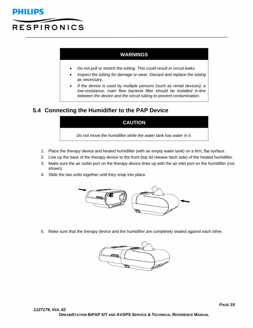
WARNINGS
• Do not pull or stretch the tubing. This could result in circuit leaks. • Inspect the tubing for damage or wear. Discard and replace the tubing
as necessary. • If the device is used by multiple persons (such as rental devices), a
low-resistance, main flow bacteria filter should be installed in-line between the device and the circuit tubing to prevent contamination.
5.4 Connecting the Humidifier to the PAP Device
CAUTION
Do not move the humidifier while the water tank has water in it.
1. Place the therapy device and heated humidifier (with an empty water tank) on a firm, flat surface. 2. Line up the back of the therapy device to the front (top lid release latch side) of the heated humidifier. 3. Make sure the air outlet port on the therapy device lines up with the air inlet port on the humidifier (not
shown). 4. Slide the two units together until they snap into place.
5. Make sure that the therapy device and the humidifier are completely seated against each other.

PAGE 20 1127179, VER. 02
DREAMSTATION BIPAP S/T AND AVAPS SERVICE & TECHNICAL REFERENCE MANUAL
5.5 Connecting the Tubing to the Humidifier 1. To attach the heated tube to the heated humidifier, line up the connector (1) at the top of the heated
tube to the top of the air outlet port (2) on the humidifier.
2. Press the tubing into place over the air outlet port until the tabs on the side of the tube click into place in the slots on the sides of the outlet port.
3. If you are using a standard tube (not shown) instead of a heated tube, simply slide the tubing over the air outlet port on the heated humidifier.

PAGE 21 1127179, VER. 02
DREAMSTATION BIPAP S/T AND AVAPS SERVICE & TECHNICAL REFERENCE MANUAL
5.6 Disconnecting the Tubing 1. To remove the heated tubing, press in the tabs (1) on the side of the tubing connector and pull the
tubing away from the outlet port.
2. If you are using a standard tube (not shown) instead of a heated tube, simply pull the tubing away from the outlet port.
5.7 Disconnecting the Devices
CAUTION
To avoid spilling, do not disconnect the humidifier from the therapy device with water in the tank. Remove the water tank from the humidifier before disconnecting the therapy device.
1. Disconnect power to the therapy device. 2. Pick up the system. 3. Place one hand on the therapy device and the other on the humidifier. 4. Press the humidifier release button (1) and pull apart to separate.
PAGE 22 1127179, VER. 02
DREAMSTATION BIPAP S/T AND AVAPS SERVICE & TECHNICAL REFERENCE MANUAL
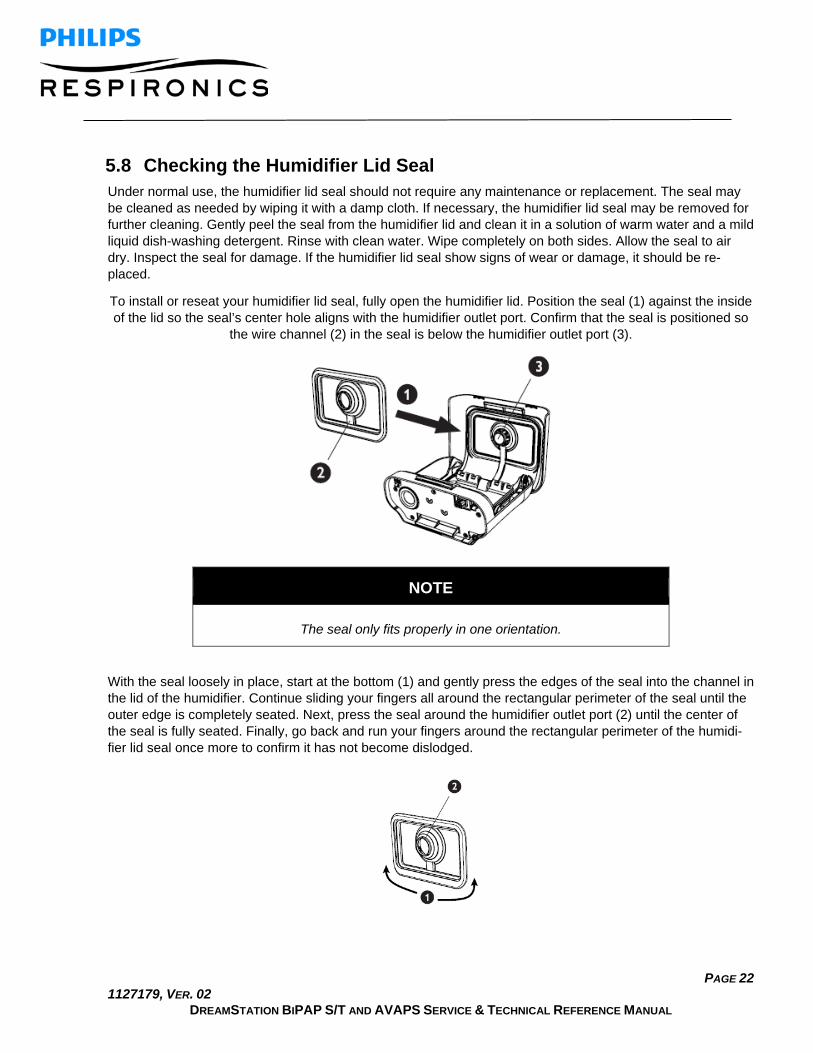
5.8 Checking the Humidifier Lid Seal Under normal use, the humidifier lid seal should not require any maintenance or replacement. The seal may be cleaned as needed by wiping it with a damp cloth. If necessary, the humidifier lid seal may be removed for further cleaning. Gently peel the seal from the humidifier lid and clean it in a solution of warm water and a mild liquid dish-washing detergent. Rinse with clean water. Wipe completely on both sides. Allow the seal to air dry. Inspect the seal for damage. If the humidifier lid seal show signs of wear or damage, it should be re-placed.
To install or reseat your humidifier lid seal, fully open the humidifier lid. Position the seal (1) against the inside of the lid so the seal’s center hole aligns with the humidifier outlet port. Confirm that the seal is positioned so
the wire channel (2) in the seal is below the humidifier outlet port (3).
NOTE
The seal only fits properly in one orientation.
With the seal loosely in place, start at the bottom (1) and gently press the edges of the seal into the channel in the lid of the humidifier. Continue sliding your fingers all around the rectangular perimeter of the seal until the outer edge is completely seated. Next, press the seal around the humidifier outlet port (2) until the center of the seal is fully seated. Finally, go back and run your fingers around the rectangular perimeter of the humidi-fier lid seal once more to confirm it has not become dislodged.

PAGE 23 1127179, VER. 02
DREAMSTATION BIPAP S/T AND AVAPS SERVICE & TECHNICAL REFERENCE MANUAL
5.9 Installing/Replacing the Air Filters
CAUTION
A properly installed, undamaged Philips Respironics blue pollen filter is required for proper operation.
The device uses a reusable blue pollen filter that can be rinsed and a disposable light-blue ultra-fine filter. The reusable blue filter screens out pollens, while the light-blue ultra-fine filter provides more complete filtration of very fine particles.
The reusable blue filter must be in place at all times when the device is operating. The ultra-fine filter is rec-ommended for people who are sensitive to tobacco smoke or other small particles.
The reusable blue filter is supplied with the device. A disposable light-blue ultra-fine filter may also be in-cluded. If your filter is not already installed when you receive your device, you must at least install the reusa-ble filter before using the device.
This device has an automatic air filter reminder. Every 30 days, the device will display a message reminding you to check your filters and replace them as directed.
NOTE
This message is a reminder only. The device does not detect the performance of the filters nor does it recognize when a filter has been rinsed or replaced.
PAGE 24 1127179, VER. 02
DREAMSTATION BIPAP S/T AND AVAPS SERVICE & TECHNICAL REFERENCE MANUAL
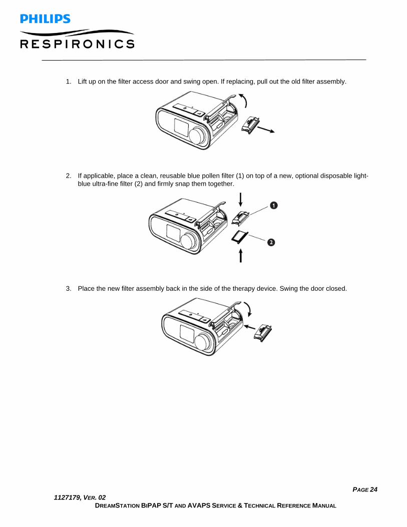
1. Lift up on the filter access door and swing open. If replacing, pull out the old filter assembly.
2. If applicable, place a clean, reusable blue pollen filter (1) on top of a new, optional disposable light-blue ultra-fine filter (2) and firmly snap them together.
3. Place the new filter assembly back in the side of the therapy device. Swing the door closed.

PAGE 25 1127179, VER. 02
DREAMSTATION BIPAP S/T AND AVAPS SERVICE & TECHNICAL REFERENCE MANUAL
5.10 Starting the Device 1. Ensure power is supplied to the device. The first screen to display will be the Philips Respironics logo,
followed by the device model screen, and then the Home screen.
The first time the device is powered on, a pop-up will prompt you to set the time on the device. The default setting is Greenwich Mean Time, but you may adjust the time in 30 minute increments to match your local time zone. If you choose to skip this initial time setting, the time can always be adjusted under the “My Setup” menu.
Note: This time setting is not displayed as a clock function on the device. It is only used to align therapy data for Provider’s data reports.
2. Press the Therapy button on top of the device to turn on airflow and begin therapy. The current delivered pressure will display on the screen.
3. Make sure that no air is leaking from the system. 4. Press the Therapy button for 2 seconds to turn off therapy.
NOTE
During therapy, it there is a mains interruption (i.e. power loss) the device will return to the Home screen once power is restored. You may resume therapy as needed.

PAGE 26 1127179, VER. 02
DREAMSTATION BIPAP S/T AND AVAPS SERVICE & TECHNICAL REFERENCE MANUAL
5.11 Navigating the Device Screens
NOTE
The display is not a touch screen. You must use the control dial to navigate the device menu.
The User Interface (UI) on this device allows you to adjust the device settings and view information about your therapy. The UI is comprised of the display screen and the control dial. Rotate the control dial in either direction to scroll through the menu options on the display screen. Press the control dial to open a menu.
To adjust a setting:
1. Rotate the control dial to your desired setting. 2. Press the control dial to select that setting. 3. Rotate the control dial to change the setting. 4. Press the control dial again to save the change.
NOTES
• The rotate dial icon on any screen indicates to rotate the dial to perform an action. The click dial icon on any screen indicates to press the dial to perform an action.
• Pressing the dial when the down arrow appears on any screen will take you to a sub-menu with more menu options. Pressing the dial when the up arrow appears on any sub-menu will return you back to the main menu.
• The screens shown throughout this manual are examples for reference only. Actual screens may vary based upon device model and provider settings.

PAGE 27 1127179, VER. 02
DREAMSTATION BIPAP S/T AND AVAPS SERVICE & TECHNICAL REFERENCE MANUAL
User Menu Navigation (Therapy On) and Optional Humidification Settings While the device is delivering therapy, you can adjust Tube Temperature or Humidifier Settings. Rotate the control dial to choose either setting. Press and rotate the dial to change the setting.
Note: If you are using the Humidifier without the Heated Tube, simply just rotate the control dial to change the Humidifier setting.

PAGE 28 1127179, VER. 02
DREAMSTATION BIPAP S/T AND AVAPS SERVICE & TECHNICAL REFERENCE MANUAL
Adjusting the Humidifier and Heated Tube Settings If you have a humidifier, you can adjust tube temperature or humidifier settings while the device is delivering therapy by following these steps:
1. Turn the control dial counter-clockwise to activate the humidifier setting and clockwise to activate the heated tube setting.
2. Press the control dial to edit the setting. 3. Turn the control dial until you reach the desired setting. The setting increments when you turn the dial
clockwise and decrements when your turn the dial counter-clockwise. Press the control dial to save the setting.
Note: If you are using the humidifier without the heated tube, simply just rotate the control dial in either direc-tion to change the humidifier setting.
Ramp Feature
The device is equipped with an optional ramp feature that can be enabled or disabled. This feature reduces the air pressure when you are trying to fall asleep and then gradually increases (ramps) the pressure until your prescription setting is reached, allowing you to fall asleep more comfortably.
If ramp is enabled on your device, after you turn on the airflow, press the Ramp button on the top of the de-vice. You can use the Ramp button as often as you wish during the night.
When you click the ramp button, the Therapy screen will change to reflect the Ramp pressure, and the green circle will reflect the gradual increase in pressure.

PAGE 29 1127179, VER. 02
DREAMSTATION BIPAP S/T AND AVAPS SERVICE & TECHNICAL REFERENCE MANUAL
User Menu Navigation (Therapy Off) From the Home screen, you can scroll between the following four options:
• My Info: This menu provides summary statistics of your therapy use. • Preheat: This function lets you warm up your humidifier for 30 minutes before starting a therapy ses-
sion. This only displays when a humidifier is attached to your device. • My Provider: This menu contains information that the provider may direct the user to read to them so
they can better assist them over the phone. • My Setup: This menu contains comfort settings that you can adjust as needed.
My Info:
When you select “My Info”, you will be able to view the following screens. You cannot change settings in the Info menu. These screens are only for reference.
Note: Additional icons may appear if optional accessories are being used (such as the oximetry module). Re-fer to the manual that accompanies the accessory for more information.
Icon Text Description
Therapy Hours This screen displays the amount of time the user is actually receiving therapy on the device for the most recent 1 day time frame. It also displays the average amount of time the patient is actually receiving therapy over the last 7 days and 30 days.
AHI AHI This screen displays the nightly Apnea/Hypopnea indices (AHI) value for the most recent 1 day time frame. It also displays the average of these individual nightly AHI values over a 7 day and a 30 day time frame. This screen only displays if your home care provider has enabled it.

PAGE 30 1127179, VER. 02
DREAMSTATION BIPAP S/T AND AVAPS SERVICE & TECHNICAL REFERENCE MANUAL
Mask Fit Displays the value “100% minus Large Leak”. Large Leak is the percentage of time that the mask leak was so high that it is no longer possible for the device to identify respiratory events with statistical accuracy. Displays the value for the most recent 1 day, as well as the values over last 7 days and 30 days. This screen only displays if your home care provider has enabled it.
Periodic Breathing
Periodic Breathing
Displays the percentage of time that the user experienced periodic breathing. Displays the value for the most recent 1 day time frame, as well as values for the last 7 days and 30 days. If you observe a large increase in the percent of time in periodic breathing indicated her, contact your home care provider for assistance. This screen only displays if your home care provider has enabled it.
90% Pressure
90% Pressure This screen displays the nightly value of 90% Pressure for the most recent 1 day time frame. It also displays the average of these individual nightly values of 90% Pressure over a 7 day and a 30 day time frame. Available on the Auto model.
Preheat:
When using a humidifier, the device can preheat the water tank for up to 30 minutes prior to starting therapy.
In order to activate the preheat mode, the blower must be “off” and a humidifier must be attached. When “Pre-heat” is selected, you will be able to turn the control dial to choose between “on” or “off”. Press the control dial again to make your selection. During the 30 minute preheat, you will still be able to use the control dial to se-lect other menu options from the Home screen.
Note: This screen only displays when a humidifier is attached.

PAGE 31 1127179, VER. 02
DREAMSTATION BIPAP S/T AND AVAPS SERVICE & TECHNICAL REFERENCE MANUAL
My Provider:
When you select “My Provider”, you will be able to view the following screens. You cannot change settings in the Provider menu. These screens are only for reference.
Icon Text Description
Therapy
This screen displays your therapy settings. Settings cannot be adjusted from this screen.
Alarms
This screen displays your alarm settings. Settings cannot be adjusted from this screen.
Provider Contact Info
This screen will display the contact information for your provider if it has been uploaded to your device.
Phone-In This screen displays the total therapy hours for the device,
the total blower hours, the total number of days used when the sessions were greater than 4 hours, and a compliance check number used by your home care provider to validate that the data provided by you is the data taken from this screen.
Compliance This screen displays your start date, the total number of
days used when the sessions were greater than 4 hours, and a check code number used by your home care provider.
VIC90 VIC 90 This Visual Inspection Check screen will display a check code number created from information gathered over the most recent 90 day period. This 15 digit number will display as: xxx.xxxx.xxxx.xxxx. Your home care provider may periodically ask you for this information.

PAGE 32 1127179, VER. 02
DREAMSTATION BIPAP S/T AND AVAPS SERVICE & TECHNICAL REFERENCE MANUAL
Upload Allows user to initiate a modem call when an optional
Cellular or Wi-Fi Accessory is installed. Signal strength is indicated at the top right of this screen. After the modem upload has finished, the screen will either display a green checkmark with the text “Completed” to indicate a successful upload, or a red X with the text “Failed” to indicate an unsuccessful upload. If the upload fails, initiate an upload a second time, or contact your home care provider if the issue persists. This screen is locked if modem is off.
Device Info This screen displays your therapy device information: serial
number, model and software version.
Performance Check
Your device is equipped with a self-diagnostic tool called “Performance Check.” This tool can evaluate your device for certain errors. It also allows you to share key device settings with your home care provider. Use Performance Check when directed to by your home care provider. At conclusion of the scan, the screen displays a green checkmark if no issue is detected. If device displays a red “X”, please contact your home care provider for assistance.

PAGE 33 1127179, VER. 02
DREAMSTATION BIPAP S/T AND AVAPS SERVICE & TECHNICAL REFERENCE MANUAL
My Setup:
When you select “My Setup”, you will be able to view the following screens. You can change the settings in the Setup menu. These screens will only display if they are available and enabled on the device.
Icon Text Description
Ramp This displays the ramp starting pressure. You can increase or decrease
the ramp starting pressure in 0.5 cm H2O increments.
Ramp Time When you set the Ramp time, the device increases the pressure from the value set on the Ramp screen to the therapy pressure setting over the length of time specified here.
Rise Time Rise time is the time it takes for the device to change from EPAP to IPAP. If rise time is prescribed for you, you can adjust the rise time from 1 to 6 to find the setting that provides you with the most comfort. A setting of 1 is the fastest rise time, while 6 is the slowest.
Flex When in S mode and Bi-Flex is enabled, you can adjust the Bi-Flex setting. This allows you to adjust the level of air pressure relief that you feel when you exhale during therapy. Your home care provider can enable or disable this feature. When your provider enables Flex, a level will already be set for you on the device. You can increase or decrease the setting from 1 to 3. The setting of 1 provides a small amount of pressure relief, with higher numbers providing additional relief. Note: If a lock icon is displayed on this screen, it indicates that your provider has locked this setting and you cannot change it
Humidification This displays the Humidification Mode being used. You can choose between Fixed or Adaptive Humidification. If a heated tube is being used, the device will automatically switch to Heated Tube Humidification Mode. A “lock” symbol will appear next to the mode setting indicating that so long as the heated tube is attached to the device, this mode cannot be changed. However, the heater plate and tube temperature settings can still be adjusted on the device Therapy screen as normal.

PAGE 34 1127179, VER. 02
DREAMSTATION BIPAP S/T AND AVAPS SERVICE & TECHNICAL REFERENCE MANUAL
Mask Type This setting allows you to adjust the level of air pressure relief based on the specific Philips Respironics mask. Each Philips Respironics mask may have a “System One” resistance control setting. Contact your home care provider if you cannot find this resistance setting for your mask. Note: If a lock icon is displayed on this screen, it indicates that your provider has locked this setting and you cannot change it.
Tube Type This setting allows you to select the correct size diameter tubing that you are using with the device. You can choose either (22) for the Philips Respironics 22 mm tubing, or (15) for the Philips Respironics 15 mm tubing. When using Heated Tubing, the device will automatically change this setting to the appropriate tubing type (15H) and you will not be able to change it. Note: Tubing is identified on the cuff with the tubing identifier symbol: “15”, “22” or “15H”. Note: If a lock icon is displayed on this screen, it indicates that your provider has locked this setting and you cannot change it.
Language This feature allows you to choose which language to display on the interface. You can also turn off (0) text mode which means the device will display the “Icon Mode” on the interface.
Check Mask Fit This feature allows you to check the fit of your mask prior to starting
therapy. This is done by measuring the amount of leak.
Wi-Fi
Wi-Fi This feature allows you to setup or edit your Wi-Fi connection. It only displays when a Wi-Fi modem is installed and turned on.
Modem Allows you to turn modem off temporarily or turn it back on. When modem is turned off, it will automatically turn on again after 3 days. Only displays when modem is installed.
Bluetooth Allows you to turn Bluetooth off and on. Also, it allows you to clear the pairing with a compatible Bluetooth device.
Time Allows you to adjust the time. The default setting is Greenwich Mean Time, but you may adjust the time in 30 minute increments to match your local time zone. Note: This time setting is not displayed as a clock function on the device. It is only used to align your therapy data for your Provider’s data reports.
Brightness This feature allows you to adjust the screen brightness. The default set-
ting is Auto. You can change the setting from 20%-100% brightness.

PAGE 35 1127179, VER. 02
DREAMSTATION BIPAP S/T AND AVAPS SERVICE & TECHNICAL REFERENCE MANUAL
Accessing Provider Mode Screens Accessing provider mode unlocks settings that cannot be modified by the user. To access provider mode:
1. Supply power to the device. 2. Once the device is powered, press and hold both the control dial and the Ramp button on the
device for at least 5 seconds. 3. You are now in Provider mode. You can choose between the following Provider mode screens.
Navigating the Provider Mode Screens The User Interface (UI) on this device allows you to adjust the device settings and view information about therapy. The UI is composed of the display screen and the control dial. Rotate the control dial in either direc-tion to scroll through the menu options on the display screen.
To adjust a setting:
1. Rotate the control dial to your desired menu option. 2. Press the control dial to select that setting. 3. Rotate the control dial to change the setting. The rotate dial icon on any screen indicates to rotate the
dial to perform an action. 4. Press the control dial again to save the change. The click dial icon on any screen indicates to press
the dial to perform an action.
NOTES
Pressing the dial when the down arrow appears on any screen will take you to a sub-menu with more menu options. Pressing the dial when the up arrow ap-pears on any sub-menu will return you back to the main menu.
The screens shown throughout this guide are examples for reference only. Actual screens may vary based upon device model and provider settings.

PAGE 36 1127179, VER. 02
DREAMSTATION BIPAP S/T AND AVAPS SERVICE & TECHNICAL REFERENCE MANUAL
Provider Settings Therapy Settings:
Choosing this screen will take you to a sub-menu where you can adjust the device therapy modes and pres-sure settings. These settings are described here.
Note: Not all settings shown here will display on the device. The display will vary based on therapy device model and device settings.
Icon Text Description
CPAP S
S/T T
PC
Mode This setting allows you to select a therapy mode. The default setting is S/T. The available modes are: BiPAP S/T: CPAP, S, or S/T BiPAP AVAPS: CPAP, S, S/T, T, or PC Note: If the therapy mode is changed while the blower is turned on, a confirmation pop-up screen appears. Select Yes if you would like to activate the selected mode.
AVAPS AVAPS This screen allows you enable or disable AVAPS. Select On to enable AVAPS and Off to disable.
AAM AAM This setting allows you to enable or disable Automated Airway Management (AAM). Select On to enable AAM and Off to dis-able.
Max Pressure
This setting displays the current maximum pressure setting. You can adjust the setting as follows: 25 cm device: 4 to 25 cmH2O in 0.5 increments 30 cm device: 4 to 30 cmH2O in 0.5 increments
EPAP Min This setting allows you to modify the Minimum EPAP setting. This setting will be the minimum level of pressure applied dur-ing the expiratory breath phase. You may adjust the setting as follows: 25 cm device: 4 cmH2O up to the lesser value of either maxi-mum pressure or 21 cmH2O 30 cm device: 4 cmH2O up to the lesser value of either maxi-mum pressure or 25 cmH2O

PAGE 37 1127179, VER. 02
DREAMSTATION BIPAP S/T AND AVAPS SERVICE & TECHNICAL REFERENCE MANUAL
EPAP Max This setting allows you to modify the Maximum EPAP setting. This setting will be the maximum level of pressure applied dur-ing the expiratory breath phase. You may adjust the setting as follows: 25 cm device: From the minimum EPAP setting up to the lesser value of either maximum pressure or 21 cmH2O 30 cm device: From the minimum EPAP setting up to the lesser value of either maximum pressure or 25 cmH2O
PS PS This screen allows you to modify the Pressure Support setting.
PS Min This setting allows you to modify the Minimum Pressure Sup-port setting. This setting is the minimum difference that is per-mitted between IPAP and EPAP. You may adjust the setting from 0 cm H2O to the difference between the maximum pres-sure setting minus the maximum EPAP setting.
PS Max This setting allows you to modify the Maximum Pressure Sup-port setting. This setting is the maximum difference that is per-mitted between IPAP and EPAP. You may adjust the setting from the minimum pressure support setting to the difference between the maximum pressure setting minus the minimum EPAP setting.
IPAP Min This setting is available only if AVAPS is enabled. Increase or decrease the setting as follows: 25 cm device: 6 to 25 cmH2O in increments of 0.5 30 cm device: 6 to 30 cmH2O in increments of 0.5 The IPAP Min Pressure must be equal to or greater than the EPAP value, and it must be less than or equal to the IPAP Max Pressure.
IPAP Max This setting is available only if AVAPS is enabled. Increase or decrease the setting as follows: 25 cm device: 6 to 25 cmH2O in increments of 0.5 30 cm device: 6 to 30 cmH2O in increments of 0.5 The IPAP Max Pressure must be equal to or greater than the IPAP Min value.
Pressure Pressure This setting is available only when CPAP mode is selected. This screen allows you to increase or decrease the CPAP pressure setting from 4 to 20 cmH20 in increments of 0.5.
IPAP IPAP This setting is available only if AVAPS is Off. Increase or de-crease the Inspiratory Positive Airway Pressure (IPAP) as fol-lows: 25 cm device: 4 to 25 cmH2O in increments of 0.5
PAGE 38 1127179, VER. 02
DREAMSTATION BIPAP S/T AND AVAPS SERVICE & TECHNICAL REFERENCE MANUAL
30 cm device; 4 to 30 cmH2O in increments of 0.5You cannot set the IPAP setting lower than the EPAP setting. IPAP is lim-ited to 25 cmH2O when the Flex feature is enabled.
EPAP EPAP This setting allows you to increase or decrease the Expiratory Positive Airway Pressure (EPAP) as follows: 25 cm device: 4 to 21 cmH2O in increments of 0.5 30 cm device: 4 to 25 cmH2O in increments of 0.5
BPM
BPM This screen allows you to modify the Breaths Per Minute set-ting. The Breaths Per Minute setting is a back-up breath rate where there is a machine-triggered breath to the patient within the defined timeframe per breath. You can choose between Off and 0 through 30 BPM. When in Timed mode, the minimum setting is 4 BPM.
Ti
Ti This screen allows you to modify the Inspiratory Time setting. You may adjust the setting from 0.5 to 3.0 seconds in 0.1 in-crements. This setting only displays if PS max is greater than zero and BPM is not set to Off or Auto.
Vt Vt This screen allows you to modify the target tidal volume from 200 to 1500 ml in 10 ml increments. This setting is available only if AVAPS is enabled.
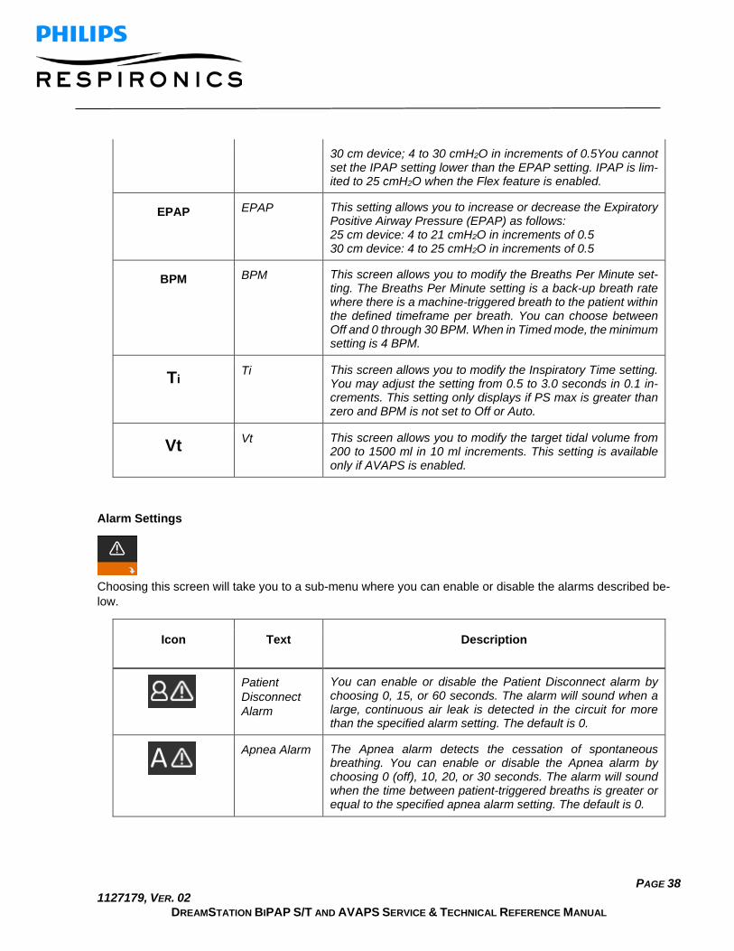
Alarm Settings
Choosing this screen will take you to a sub-menu where you can enable or disable the alarms described be-low.
Icon Text Description
Patient Disconnect Alarm
You can enable or disable the Patient Disconnect alarm by choosing 0, 15, or 60 seconds. The alarm will sound when a large, continuous air leak is detected in the circuit for more than the specified alarm setting. The default is 0.
Apnea Alarm The Apnea alarm detects the cessation of spontaneous breathing. You can enable or disable the Apnea alarm by choosing 0 (off), 10, 20, or 30 seconds. The alarm will sound when the time between patient-triggered breaths is greater or equal to the specified apnea alarm setting. The default is 0.

PAGE 39 1127179, VER. 02
DREAMSTATION BIPAP S/T AND AVAPS SERVICE & TECHNICAL REFERENCE MANUAL
Low Min Vent Alarm
You can enable or disable this alarm by choosing 0 (off) to 99 lpm in 1.0 increments. The alarm will sound when the calcu-lated minute ventilation is less than or equal to the specified setting. The default is 0.
Low Tidal Vol-ume
You can enable or disable this alarm by selecting On or Off. This alarm will sound if IPAP max is reached and the target tidal volume is not achieved. This alarm is only available when AVAPS is enabled. The default is Off.

PAGE 40 1127179, VER. 02
DREAMSTATION BIPAP S/T AND AVAPS SERVICE & TECHNICAL REFERENCE MANUAL
Comfort Settings:
Choosing this screen will take you to a sub-menu where you can adjust the humidification and pressure com-fort settings. These settings are described here.
Note: Not all settings shown here will display on the device. The display will vary based on therapy device model and device settings.
Icon Text Description
Humidification This setting allows you to select the Humidification Mode being
used. You can choose between Fixed or Adaptive (A) Humidification. If a heated tube is attached to the device, then the device will automatically switch to Heated Tube Humidification Mode. Fixed mode applies a constant heat on the humidifier heater plate. Under certain conditions and settings, this mode can allow condensation to occur in the tube. Adaptive mode adapts the heater plate temperature to the ambient conditions in the room, and is designed to not allow condensation to occur in the tube.
Humidifier This setting allows you to choose the desired humidity setting
for the humidifier: 0, 1, 2, 3, 4 or 5.
Tube Temperature
This setting allows you to choose the desired temperature for the heated tube: 0, 1, 2, 3, 4 or 5.
Ramp Time This enables you to modify the Ramp time setting in 5 minute increments. The range for this setting is 0 (off) to 45 minutes. This setting only displays if EPAP min is greater than 4 cm H2O.
Ramp Start You can increase or decrease the ramp starting pressure in 0.5 cm H2O increments. You may adjust the setting from 4 cm H2O to the EPAP min setting. This setting only displays if Ramp time is not zero and EPAP min is greater than 4 cm H2O.
Flex When in S mode, this screen displays the comfort mode
setting. You can select None or Bi-Flex.
Flex Setting When in S mode and Bi-Flex is enabled, you can adjust the Bi-
Flex setting by selecting 1, 2, or 3. This setting allows you to adjust the level of air pressure relief that the patient feels when exhaling during therapy. The setting of 1 provides a small

PAGE 41 1127179, VER. 02
DREAMSTATION BIPAP S/T AND AVAPS SERVICE & TECHNICAL REFERENCE MANUAL
amount of pressure relief, with higher numbers providing addi-tional relief. The default setting of Off. Note: If you do not lock the Bi-Flex setting, the patient has ac-cess to the setting and can adjust it from 1-3. They cannot dis-able Bi-Flex. Note: Bi-Flex is available up to 25 cmH2O in S mode.
Flex Lock This enables you to lock the Flex setting if you do not want the patient to change it.
Rise Time Rise time is the time it takes for the device to change from the
expiratory pressure setting to the inspiratory pressure setting. This screen allows you to adjust the rise time so you can find the desired setting. A setting of 1 is the fastest rise time, while 6 is the slowest.
Rise Time Lock This enables you to lock the Rise Time setting. Select Off to
allow the user to adjust the Rise Time setting from 1-6. Select On to lock the user from adjusting the setting.
Tube Type This setting allows you to select the correct size diameter
tubing that you are using with the device. You can choose either (22) for the Philips Respironics 22 mm tubing, or (15) for the Philips Respironics 15 mm tubing. When using Heated Tubing, the device will automatically change this setting to the appropriate tubing type (15H).
Tube Type Lock This enables you to lock the Tubing type setting for either the 15 mm or the 22 mm tubing if you do not want the patient to change it.
Mask Type This setting allows you to select the appropriate Mask Type
resistance setting (also known as System One Resistance Control) for your Philips Respironics mask. This feature allows the device to adjust the level of pressure compensation to match your mask. Refer to the packaging of your mask to identify the resistance setting for your mask. Note: It is important to use the appropriate “Mask Type” resistance setting to ensure proper pressure delivery to the patient.
Mask Type Lock This enables you to lock the Mask Type resistance setting if you do not want the patient to change it.
Check Mask Fit You can enable or disable the check mask fit setting. This
feature allows the patient to check the fit of their mask prior to starting therapy. This is done by measuring the amount of leak in the patient circuit.

PAGE 42 1127179, VER. 02
DREAMSTATION BIPAP S/T AND AVAPS SERVICE & TECHNICAL REFERENCE MANUAL
Device Settings:
Choosing this screen will take you to a sub-menu where you can adjust the way the device displays infor-mation. These settings are described here.
Note: Not all settings shown here will display on the device. The display will vary based on therapy device model and device settings.
Icon Text Description
AHI
Show AHI/Fit/PB
You can select whether or not the Apnea/Hypopnea index, Mask Fit averages, and Periodic Breathing averages are displayed on the Patient Info screens.
cmH2O or
hPa
cmH2O or hPa
You can select the units of pressure that are displayed on the screen.
Language This feature allows you to choose which language to display on the interface.
Clear Default Reminders
This setting turns off the default patient reminders that are enabled in the therapy device from the factory. Note: This does not turn off additional reminders that you may have activated in Encore. Encore messages must be cleared or modified in Encore.
Reset Data Use the Reset Data function to clear patient data from the ther-apy device, as well as an SD card and modem (if installed). After you press the control dial to execute Reset Data, the de-vice will display a message asking you to confirm the reset. Press the control dial again to reset data in the device. Note: Reset Data resets Blower Hours that are visible to the patient, but it does not reset Machine Hours in the Provider Menu.
Reset Blower Hours
Select Yes if you want to reset the blower hours (e.g., to track device usage between patients).
Reset Therapy Hours
Select Yes if you want to reset the therapy hours back to the default of 0 hours.

PAGE 43 1127179, VER. 02
DREAMSTATION BIPAP S/T AND AVAPS SERVICE & TECHNICAL REFERENCE MANUAL
Provider Lock This setting unlocks provider mode. While unlocked, the pro-
vider mode key sequence is not needed to access the therapy, comfort, and device settings. The unlocked icon appears on the screen while in this mode.
Info Screens:
Choosing this screen will take you to a sub-menu where you can view information on patient usage. The Info screens are described in above sections of this manual.
Return to Patient Mode:
Choosing this screen will exit Provider mode and the device will return to the Patient mode. Provider mode will also time out after 5 minutes of inactivity and automatically return to the Patient mode.

PAGE 44 1127179, VER. 02
DREAMSTATION BIPAP S/T AND AVAPS SERVICE & TECHNICAL REFERENCE MANUAL
5.12 Therapy Event Detection
Text Description
Obstructed airway apnea/ Clear airway apnea detection
An apnea is detected when there is an 80% reduction in airflow from baseline for at least 10 seconds or if there is no airflow detected for 10 seconds. During the apnea, one or more pressure test pulses are delivered by the device. The device evaluates the response of the patient to the test pulse(s) and assesses whether the apnea has occurred while the patient has a clear airway or an obstructed airway. The airway is determined to be clear if the pressure test pulse generates a significant amount of flow; otherwise, the airway is determined to be obstructed.
RERA detection
RERA (Respiratory effort-related arousal) is defined as an arousal from sleep that follows a 10 second or longer sequence of breaths that are characterized by increasing respiratory effort, but which does not meet criteria for an apnea or hypopnea. Snoring, though usually associated with this condition, need not be present. The RERA algorithm monitors for a sequence of breaths that exhibit both a subtle reduction in airflow and progressive flow limitation. If this breath sequence is terminated by a sudden increase in airflow along with the absence of flow limitation, and the event does not meet the conditions for an apnea or hypopnea, a RERA is indicated.
Periodic breathing
A persistent waning and waxing breathing pattern which repeats itself between 30 and 100 seconds. The nadir of the breathing pattern is characterized by at least a 40% reduction in airflow from an established baseline flow. The pattern must be present for several minutes before it can be identified as periodic breathing.
Hypopnea detection
A hypopnea is detected when there is an approximately 40% reduction in airflow from baseline for at least 10 seconds.
Snore detection
Vibration snore is disabled at pressures greater than 16 cmH2O in CPAP mode. Vibration snore is disabled at IPAP settings greater than 20 cmH2O or max pressure support (IPAP – EPAP) greater than or equal to 10 cmH2O in bi-level modes. It is also disabled during any machine triggered breaths when EPAP settings are greater than or equal to 10 cmH2O.
Large leak The level of leak is so large, it is no longer possible to determine respiratory events with statistical accuracy.

PAGE 45 1127179, VER. 02
DREAMSTATION BIPAP S/T AND AVAPS SERVICE & TECHNICAL REFERENCE MANUAL
5.13 Connecting to Wi-Fi (if available) If your device has a Wi-Fi accessory installed and enabled, follow the steps below to connect your device to Wi-Fi. For additional information, see the instructions included with your Wi-Fi accessory.
1. From the My Setup menu, select Wi-Fi. 2. The Wi-Fi accessory will search for available networks within range of your device. Press the control
dial to select your network.
3. If your network is secure, a Passkey pop-up screen appears. Enter your network password, and then select the green check mark.
4. Once your password is entered, the Wi-Fi accessory will connect to your network. When the com-pleted screen appears, press the control dial to close the screen.
NOTE
If a red X appears over the signal strength icon, the Wi-Fi accessory detects a wireless router but cannot connect to it. Try repeating steps 1-3 above, mak-ing sure you select the correct network and enter the correct password.

PAGE 46 1127179, VER. 02
DREAMSTATION BIPAP S/T AND AVAPS SERVICE & TECHNICAL REFERENCE MANUAL
5.14 Bluetooth Wireless Technology The device has Bluetooth wireless technology, which is one method by which you can transfer the therapy device’s data to DreamMapper. DreamMapper is a mobile and web-based system designed to help obstruc-tive Sleep Apnea (OSA) patients enhance their sleep therapy experience.
Pairing to your Bluetooth enabled Mobile Device
NOTES
• You will not receive alarms on your mobile device through the Bluetooth connection.
• You can only pair your therapy device to one mobile device at any given time.
• Pairing works best when your therapy device and mobile device are in the same room.
• The current version of DreamMapper will guide you through these instructions.
• After initiating pairing, you will have 30 seconds to complete the setup. After this time, it will be cancelled automatically.
Follow the steps below to manually pair to your mobile phone or tablet.
1. With your therapy device powered up and the blower off, initiate Bluetooth Setup from the DreamMapper mobile app.
2. If you need to select from a list of available Bluetooth devices, the therapy device will appear as “PR BT XXXX” (XXXX will be the last four digits of the serial number listed on your therapy device).
3. Your mobile device will require you to confirm pairing via one of these two methods: Enter a PIN code • Enter a PIN Code
The following icon will appear on your therapy device screen with Pair?:
Rotate the therapy device’s control dial to select Yes, and press the control dial. Your therapy device will display a 6-digit PIN. Enter this PIN on your mobile device to complete pairing.
• Confirm a PIN code The following icon will appear on your therapy device screen with a 6-digit PIN and Pair?:
Verify that the PIN is the same on both the therapy device and the mobile device. If so, rotate the therapy device’s control dial to select Yes and then press the control dial. Then, accept on the mobile device to complete pairing.
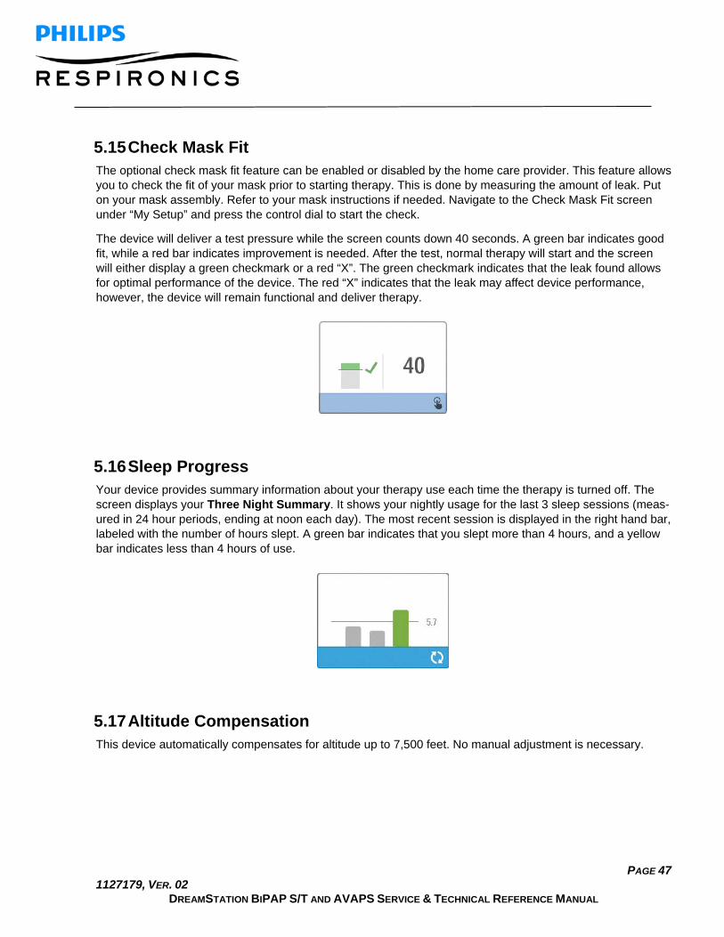
PAGE 47 1127179, VER. 02
DREAMSTATION BIPAP S/T AND AVAPS SERVICE & TECHNICAL REFERENCE MANUAL
5.15 Check Mask Fit The optional check mask fit feature can be enabled or disabled by the home care provider. This feature allows you to check the fit of your mask prior to starting therapy. This is done by measuring the amount of leak. Put on your mask assembly. Refer to your mask instructions if needed. Navigate to the Check Mask Fit screen under “My Setup” and press the control dial to start the check.
The device will deliver a test pressure while the screen counts down 40 seconds. A green bar indicates good fit, while a red bar indicates improvement is needed. After the test, normal therapy will start and the screen will either display a green checkmark or a red “X”. The green checkmark indicates that the leak found allows for optimal performance of the device. The red “X” indicates that the leak may affect device performance, however, the device will remain functional and deliver therapy.
5.16 Sleep Progress Your device provides summary information about your therapy use each time the therapy is turned off. The screen displays your Three Night Summary. It shows your nightly usage for the last 3 sleep sessions (meas-ured in 24 hour periods, ending at noon each day). The most recent session is displayed in the right hand bar, labeled with the number of hours slept. A green bar indicates that you slept more than 4 hours, and a yellow bar indicates less than 4 hours of use.
5.17 Altitude Compensation This device automatically compensates for altitude up to 7,500 feet. No manual adjustment is necessary.

PAGE 48 1127179, VER. 02
DREAMSTATION BIPAP S/T AND AVAPS SERVICE & TECHNICAL REFERENCE MANUAL
5.18 Performance Check Device Screening Tool Performance Check troubleshooting tool is a self-diagnostic utility built into the therapy device. It allows you to quickly evaluate a therapy device remotely. If a patient calls indicating that their therapy does not seem to be operating properly, just direct them to click on Performance Check in the patient’s My Provider menu. The check operates the blower and screens the device for any operation errors. The screen then displays whether the device passed the check (displays a green check mark) or should be returned for service (displays a red X). If a modem is installed, Performance Check will automatically upload a troubleshooting dashboard to the Encore Anywhere patient management software. This dashboard gives you an overview of key device set-tings and statistics to help make troubleshooting over the phone easier. If there is not a modem installed in the therapy device, you can direct the patient to read you the five codes off the Performance Check screen over the phone. You can decode these codes in EncoreAnywhere, EncorePro or Encore Basic to populate the troubleshooting dashboard.
5.19 Accessories There are several accessories available for the DreamStation system such as a Humidifier, Cellular Modem, Wi-Fi Accessory or a Link Module. When using optional accessories, always follow the instructions enclosed with the accessories.
CAUTION
Pins of connectors should not be touched. Connections should not be made to these connectors unless ESD precautionary procedures are used. Precautionary procedures include methods to prevent build-up of electrostatic charge (e.g., air conditioning, humidification, conductive floor coverings, non-synthetic clothing), discharging one’s body to the frame of the equipment or system or to earth or a large metal object, and bonding oneself by means of a wrist strap to the equipment or system or to earth.
Humidifier with or without Heated Tubing You can use the heated humidifier and the heated tube with the device. A humidifier may reduce nasal dry-ness and irritation by adding moisture to the airflow.
WARNING
For safe operation, the humidifier must always be positioned below the breathing circuit connection at the mask. The humidifier must be level for proper operation.
SD Card The DreamStation device comes with an SD card inserted in the SD card slot on the side of the device. The SD card records information for the home care provider. Your home care provider may ask you to periodically remove the SD card and send it to them for evaluation.

PAGE 49 1127179, VER. 02
DREAMSTATION BIPAP S/T AND AVAPS SERVICE & TECHNICAL REFERENCE MANUAL
Cellular Modem The DreamStation Cellular Modem is designed for use with select Philips Respironics therapy devices. Once installed, it automatically transfers data between the therapy device and Philips Respironics proprietary com-pliance software. The cellular modem is able to receive oximetry data and transfer it to the therapy device.
Wi-Fi Accessory Wi-Fi accessory is designed for use with select Philips Respironics therapy devices. Once installed and con-nected to a local Wi-Fi network it can transfer data between the therapy device and Philips Respironics propri-etary compliance software. If available on your model, the accessory is able to receive oximetry data and transfer it to the therapy device.
Link Module The Link Module is able to receive oximetry data and transfer it to the therapy device for home use or in a la-boratory setting. For use in a laboratory setting, the Link Module also includes an RS-232 (or “DB9”) port to allow remote control of the DreamStation BiPAP autoSV device by a personal computer.
Oximeter The DreamStation oximetry system, when part of the DreamStation BiPAP autoSV device, measures and dis-plays %SpO2 and heart rate in adult patients.
WARNING
Use only Philips Respironics recommended SpO2 cables and pulse oximeter sensors. Use of incompatible sensors can result in inaccurate pulse oximeter performance.
5.20 Updating the Software Using the SD Card You can update the device software using the SD card. The software update must be done when the therapy is off.
1. Insert an SD card with the new software version into the device. A pop-up screen appears asking “Would you like to upgrade software?”
2. Turn the control dial to select Yes and then press the control dial to start the upgrade. The busy icon appears while the upgrade is in progress. Do not remove power from the device.
3. If the software update is successful, the Change Accepted icon appears on the screen. Removed the SD card from the device to restart the device and use the new software.
4. If an SD card error is detected, the Change Rejected icon appears . Remove the SD card and
reinsert. If the alert continues to occur, try a new SD card.

PAGE 50 1127179, VER. 02
DREAMSTATION BIPAP S/T AND AVAPS SERVICE & TECHNICAL REFERENCE MANUAL
Chapter 6. Troubleshooting and Error Codes 6.1 Introduction This section provides an overview of device troubleshooting, along with corrective actions to take based on the outcome. You will also find bench checkout procedures, along with tables that include error codes and descriptions. In addition, you will find troubleshooting guidance based on issues unrelated to error codes.
6.2 Bench Checkout
PAP Device: If the PAP device was returned with a Humidifier, perform these steps with and without the Humidifier if nec-essary.
1. Visually inspect the outside of the device for physical damage and broken/missing parts. 2. Verify all components are aligned/seated properly, and not damaged. 3. Turn on the device and verify proper operation of the unit. 4. If the device was returned with a power cord and power supply, verify that they function properly
with/without the device. 5. Turn on the device and verify proper operation of the unit. 6. Verify the device pressure by using a manometer. 7. Listen to the device for noisy operation or loose components. 8. Verify the alarms function properly (refer to section 6.3.3). 9. Refer to section 6.4 to retrieve the device Error Log, and refer to the chart for troubleshooting
guidance based on the Error. 10. Check all other components for physical damage. 11. Perform repairs to the device as necessary.
Humidifier: If the Humidifier was returned with a PAP device, perform these steps with the returned PAP device.
1. Visually inspect the outside of the device for physical damage and broken/missing parts. 2. Verify all seals and all other components are aligned/seated properly, and not damaged. 3. Connect the Humidifier to the PAP device and apply power. 4. If the device was returned with a power cord and power supply, verify that they function properly
with/without the device. 5. Verify the Heater Plate operates (refer to section 6.3.2). 6. If a Heated Tube was returned, connect the Tube to the Humidifier, adjust the Heated Tube setting
using the UI Knob to any setting but 0, and verify the Tube is warming. 7. Verify the pressure at the Humidifier ISO Port by using a manometer. 8. Check all other components for physical damage. 9. Perform any repairs as necessary.

PAGE 51 1127179, VER. 02
DREAMSTATION BIPAP S/T AND AVAPS SERVICE & TECHNICAL REFERENCE MANUAL
6.3 System Verification
NOTE
Use the test data sheet located at the end of this section to record the results of these procedures.
Pressure Verification Please use the following instructions to ensure that the device is functioning properly. You will need the fol-lowing equipment to verify the pressure:
• Philips Respironics Pressure Calibration Kit, which includes: o Philips Respironics Whisper Swivel II (REF 332113) o Philips Respironics O2 Enrichment Final Assembly (REF 312710) o 0.25 inch orifice (REF 332353) o End cap, stopper, or equivalent
• Philips Respironics flexible tubing (REF 622038) • Pressure tubing, as needed • Pollen Filter (REF 1122446 – single pack)
Philips Respironics Digital Manometer (REF 302227) or equivalent, with the following minimum specifications:
o 0 - 30 cm H2O (or better) o ±0.3 cm H2O accuracy o ±0.1 cm H2O resolution
To verify the pressure on a BiPAP S/T or AVAPS device, complete the following steps. Refer to the figure above for proper configuration.
1. Connect the patient tubing to the device/humidifier outlet port (4). 2. Connect the Whisper Swivel II to the end of the patient tubing (1). 3. Place the O2 Enrichment Attachment on the end of the Whisper Swivel II (2). 4. Place the end cap (3) on the end of the O2 Enrichment attachment. 5. Connect a Digital Manometer (6) to the pressure pick-off (5) on the O2 Enrichment attachment. 6. Supply power to the device, and then access the Provider menu. Set the device to CPAP Mode and
the pressure value 4 cmH2O. 7. Exit the Provider menu, and then press the Therapy button to start therapy. 8. Record the manometer reading on the test data sheet. 9. Press and hold the Therapy button for 2 seconds to end therapy.

PAGE 52 1127179, VER. 02
DREAMSTATION BIPAP S/T AND AVAPS SERVICE & TECHNICAL REFERENCE MANUAL
10. Enter the Provider menu and set the CPAP pressure value to 20 cmH2O. Record the manometer value on the test data sheet, and then stop therapy.
11. Set the device to S mode and set the IPAP pressure to 10 cm H2O and EPAP pressure to 5 cm H2O. • Remove the end cap. • Fit 0.25 inch orifice, (REF 332353). • Exit the Provider menu. • Press the Therapy button to start therapy.
12. Occlude and then open the outlet repeatedly to verify that the device triggers and cycles between IPAP and EPAP modes on the display screen and the manometer. Record the results on the test data sheet.
13. Set the device to S/T mode and set the IPAP pressure to 10 cmH2O, the EPAP pressure to 5 cmH2O, BPM to 10, Inspiration time (Ti) to 2.0, and Rise Time to 2. Exit the Provider menu, and then start therapy.
14. Visually verify that the device switches between IPAP and EPAP modes on the display screen and record the results on the test data sheet.
Heated Humidifier Performance Confirmation Humidifier preheat mode can be used to determine if the DreamStation Humidifier is working properly. The following steps should be followed to confirm the performance of the humidifier.
WARNINGS
It is important to follow the exact steps below when performing this test in order to avoid injury. Read all steps first, before performing this test. Do not place your hand directly on the heater plate at any time as it could result in an injury.
1. While the device and humidifier are not running, place your hand above the heater plate (without touching it) to assess the temperature of the heater plate when the humidifier is off for later comparison.
2. Disconnect the patient tubing (if attached) and remove the water chamber. 3. Verify that the humidification is enabled and set to 1. 4. In order to activate the preheat mode, the blower must be off and a humidifier must be attached.
From the device’s Preheat screen, turn the control dial to select On. The device will now be in preheat mode and the humidifier icon will illuminate during this time with the setting number 1.
5. Allow the device to run in preheat mode for 30 seconds. Place your hand above the heater plate (without touching it) to confirm an increase in heater plate temperature.
WARNING
Do not place your hand directly on the heater plate at any time as it could result in an injury.

PAGE 53 1127179, VER. 02
DREAMSTATION BIPAP S/T AND AVAPS SERVICE & TECHNICAL REFERENCE MANUAL
6. Press the Therapy button to enter therapy and end preheat mode. 7. Press and hold the Therapy button for 2 seconds to end therapy. 8. Record the results on the data sheet.
Verifying the Alarms Use the test orifice from the Verifying the Pressure instructions and the patient’s prescription for the follow-ing tests. Make sure the blower is turned On before starting each alarm test.
6.3.3.1 Patient Disconnect Alarm Test
NOTE
The Patient Disconnect Alarm relies on a fixed relationship between the patient pressure settings and the open circuit flow of the patient circuit. You must verify that the Patient Disconnect Alarm operates properly with the prescribed patient pressures and circuit.
1. Set the Patient Disconnect Alarm setting to 15 seconds.
2. Exit to the Home screen.
3. Connect a standard circuit with Whisper Swivel II and an end cap.
4. Press the Therapy button to start therapy.
5. Simulate breathing by alternately occluding and opening the outlet port.
6. Remove the end cap.
7. Verify that the Patient disconnect alarm occurs in approximately 15 seconds.
8. Press the control dial to silence the alarm, and wait for one minute until the alarm sounds again.
9. Press the control dial twice to silence and clear the alarm.
10. Replace the closed end cap.
11. Press and hold the Therapy button for 2 seconds to end therapy.
12. Set the Patient Disconnect alarm to Off.
13. Record the patient disconnect alarm test results on the data sheet.

PAGE 54 1127179, VER. 02
DREAMSTATION BIPAP S/T AND AVAPS SERVICE & TECHNICAL REFERENCE MANUAL
6.3.3.2 Apnea Alarm Test
1. Set the Apnea alarm setting to 10 seconds. Exit to the Home screen.
2. Press the Therapy button to start therapy.
3. Remove the closed end cap. Verify that the device triggers to IPAP.
4. Replace the closed end cap. Verify that the Apnea alarm occurs in approximately 10 seconds.
5. Press the control dial twice to silence and clear the alarm.
6. Press and hold the Therapy button for 2 seconds to end therapy.
7. 7. Set the Apnea Alarm setting to Off.
8. Record the Apnea alarm test result on the data sheet.
6.3.3.3 Low Minute Ventilation Alarm Test
1. Press the Therapy button to start therapy.
2. Simulate 6 breaths by alternately occluding and opening the outlet port for 2 seconds each.
3. With the therapy still on, set the Low Minute Ventilation Alarm setting = 10.0 LPM.
4. Simulate 1 or 2 breaths by occluding and opening the outlet port.
5. Verify that the Low Minute Ventilation alarm occurs.
6. Press and hold the Therapy button for 2 seconds to end therapy.
7. Set the Low Minute Ventilation Alarm setting to 0.0 (Off).
8. Record the Low Minute Ventilation alarm test result on the data sheet.
6.3.3.4 Loss of Power Alarm Test
1. While the device is providing therapy, remove the power connector and verify that Loss of Power alarm sounds.
2. Reconnect power and verify that the device resumes providing therapy.
3. Record the test result on the data sheet.
IMPORTANT NOTE
When testing is complete, and before patient use, adjust the device to the appropriate patient settings if applicable.

PAGE 55 1127179, VER. 02
DREAMSTATION BIPAP S/T AND AVAPS SERVICE & TECHNICAL REFERENCE MANUAL
System Checkout Data Sheet
Device Information
Notification # (if applicable) Model #/Serial # Model name Device firmware version Blower hours
Humidifier Verification
Test Result (circle one)
Humidification test: heater plate operation Pass/Fail
System and Alarm Verification
Test Result/Tolerance Result (circle one)
CPAP @ 4 cmH2O [ ] +/- 1 cmH2O Pass/Fail
CPAP @ 20 cmH2O [ ] +/- 2 cmH2O Pass/Fail
S mode trigger performance Pass/Fail
S/T mode - machine-delivered breath Pass/Fail
Apnea Pass/Fail
Patient Disconnect Pass/Fail
Low Minute Ventilation Pass/Fail
Loss of Power Pass/Fail

PAGE 56 1127179, VER. 02
DREAMSTATION BIPAP S/T AND AVAPS SERVICE & TECHNICAL REFERENCE MANUAL
6.4 Service Center Tools Suite The Service Center Tools Suite will provide you the necessary tools to view the device’s error/event log, along with additional functions necessary to service the device. To download the software you must log onto my.respironics.com. If you do not have an account, click on the “Sign Up” link to register for an account.

PAGE 57 1127179, VER. 02
DREAMSTATION BIPAP S/T AND AVAPS SERVICE & TECHNICAL REFERENCE MANUAL
Service Center Tools Suite Installation and Device Connection Process 1. Once you have opened the Service and Software Documentation page, click on the Utility Tools link
on the left side or drop down menu of the page. 2. Click on the Download button adjacent to the Service Center Tools Suite (v3.8 or greater).
3. Save the Service Center Tools Installer to your PC (default directory is recommended). 4. To use the Service Center Tools suite, launch the Service Center Tools Suite software.
5. Connect power to the device. 6. Connect the Link Module (PN 1120293) between the Device and PC COM port 1 using the DB-9
Serial Cable. 7. Select a function to execute. Refer to the table below for functions that are available for DreamStation
devices:

PAGE 58 1127179, VER. 02
DREAMSTATION BIPAP S/T AND AVAPS SERVICE & TECHNICAL REFERENCE MANUAL
Available Functions for DreamStation Devices
Read SN & MN This function allows you to read the serial and model numbers of the device.
RTC Calibration This function allows you to set and verify the real time clock on the device.
Get Session ID This function allows you to retrieve the session ID on the device. The session ID is a unique number that interfaces with Encore.
Set Session ID This function allows you to set the session ID on the device. This should only be executed when the Therapy PCA is replaced on a device.
Read Time Meters This function allows you to read the therapy and blower hours on the device.
DS Logs (DreamStation Logs)
This function allows you the retrieve certain data from the device, including device error codes (if any are logged). Within this function, you can also choose to clear the error log, device log, therapy and/or blower hours, and first time use. This function will also prompt you if the returned power cord and power supply are functional, with the options of “Yes”, “No”, or “Not Returned”. See Figure 5-4 below for an example of data retrieved from the device.

PAGE 59 1127179, VER. 02
DREAMSTATION BIPAP S/T AND AVAPS SERVICE & TECHNICAL REFERENCE MANUAL
Clearing the Error and Device Logs
• There should be no errors on the device after repairs are made. If there are any errors logged on the device that do not affect device functionality, the error(s) must be cleared. Refer to section 6.3 for a list of error codes, descriptions and corrective actions.
• The device log cannot be read, however the device log should be cleared on the device as part of routine servicing.
Clearing Therapy Hours and Blower Hours
• If the PCA is NOT replaced during device servicing, the therapy hours should only be cleared if the device is going to a different patient. Otherwise, the therapy hours should remain on the de-vice.
• If the PCA is NOT replaced during device servicing, the blower hours should be cleared only if the Blower is replaced. Otherwise, the blower hours should remain on the device.
Setting the Session ID
NOTE
The Session ID should be set on the device when the Therapy PCA is replaced. If the Therapy PCA is not replaced on the device, the Session ID should not be set.
1. Connect the device to your PC and launch the Service Center Tools Suite. 2. Select QPAP SET SESSIONS ID, then click on the EXECUTE TOOL button. 3. Enter the date manufactured of the PAP device in the DATE MANUFACTURED box, then select the
SET SESSION ID button.
NOTE
The Manufactured Date is located on the device’s serial/model number label in format YYYY-MM-DD. When entering the date into the software application, do not include the dashes (-).
Example Label Only

PAGE 60 1127179, VER. 02
DREAMSTATION BIPAP S/T AND AVAPS SERVICE & TECHNICAL REFERENCE MANUAL
4. The following screen should appear indicating the Session ID has been set.
5. Select the OK button. 6. Select the New Device button if you are setting sessions on multiple devices, otherwise, select the
Close button to exit the tool.
Resetting First Time Use
• The First Time Use should only be reset if the device is going to a different patient.

PAGE 61 1127179, VER. 02
DREAMSTATION BIPAP S/T AND AVAPS SERVICE & TECHNICAL REFERENCE MANUAL
6.5 Device Error Codes The following table lists the error level and descriptions for the DreamStation devices.
Error Level Description
STOP The error information is recorded in NVRAM and the unit is placed into Safe State. The only functionality available to the user is serial communication, turning off the audible alarm via a key press and removing power.
REBOOT The error information is recorded in NVRAM and the unit is rebooted. The fifth occurrence of a REBOOT level error within a 24 hour period (while power is maintained), will be promoted by the system to a STOP level error.
ABORT The error information is recorded in NVRAM. The fifth occurrence of an ABORT level error within a 24 hour period (while power is maintained), will be promoted by the system to a STOP level error. This error is similar to a Reboot-Level Error with the exception that the system is unable to handle the error prior to the reset, e.g. watchdog timeout.
CONTINUE The error information is recorded in NVRAM and the unit continues to operate without noticeable alteration.
The following table should be used to aid in troubleshooting device error codes for the DreamStation devices.
Code Error Name Error Level Failed Component Actions
E-0 ERR_NONE STOP N/A N/A
E-3 ERR_INT_RAM REBOOT CPU 1. If error was NOT Last Stop Error, clear error log and test.
2. If error was Last Stop Error, replace PCA and test.

PAGE 62 1127179, VER. 02
DREAMSTATION BIPAP S/T AND AVAPS SERVICE & TECHNICAL REFERENCE MANUAL
Code Error Name Error Level Failed Component Actions
E-4 ERR_NULL_PTR REBOOT CPU 1. If error was NOT Last Stop Error, clear error log and test.
2. If error was Last Stop Error, replace PCA and test.
E-6 ERR_STATE_MACHINE REBOOT
CPU 1. If error was NOT Last Stop Error, clear error log and test.
2. If error was Last Stop Error, replace PCA and test.
E-7 ERR_SOFTWARE REBOOT CPU 1. If error was NOT Last Stop Error, clear error log and test.
2. If error was Last Stop Error, replace PCA and test.
E-8 ERR_CRC_FAILED STOP CPU 1. Replace PCA and retest
E-10 ERR_WDOG_TEST_RAM REBOOT CPU 1. If error was NOT Last Stop Error, clear error log and test. 2. If error was Last Stop Error, replace PCA and test.
E-11 ERR_WDOG_TEST REBOOT CPU 1. If error was NOT Last Stop Error, clear error log and test.
2. If error was Last Stop Error, replace PCA and test.
E-15 ERR_CYCLE_HANDLER_OVERRUN
REBOOT CPU 1. If error was NOT Last Stop Error, clear error log and test.
2. If error was Last Stop Error, replace PCA and test.

PAGE 63 1127179, VER. 02
DREAMSTATION BIPAP S/T AND AVAPS SERVICE & TECHNICAL REFERENCE MANUAL
Code Error Name Error Level Failed Component Actions
E-19 ERR_WDOG_TIMEOUT ABORT CPU 1. If error was NOT Last Stop Error, clear error log and test.
2. If error was Last Stop Error, replace PCA and test.
E-20 ERR_MOTOR_SPINUP_FLUX_LOW
REBOOT 1. Motor connection 2. Blower Box 3. PCA
1. Reseat motor connector, clear error log and test. 2. If error still occurs, replace blower and retest. 3. If 2nd retest fails, replace PCA.
E-21 ERR_MOTOR_VBUS_HIGH
STOP PCA 1. Replace PCA and retest
E-22 ERR_MOTOR_FLUX_MAGNITUDE
REBOOT 1. Motor connection 2. Blower Box 3. PCA
1. Reseat motor connector, clear error log and test. 2. If error still occurs, replace blower and retest. 3. If 2nd retest fails, replace PCA.
E-23 ERR_MOTOR_OVERSPEED
REBOOT PCA 1. If error was NOT Last Stop Error, clear error log and test.
2. If error was Last Stop Error, replace PCA and test.
E-24 ERR_MOTOR_SPEED_REVERSE
REBOOT PCA 1. If error was NOT Last Stop Error, clear error log and test.
2. If error was Last Stop Error, replace PCA and test.

PAGE 64 1127179, VER. 02
DREAMSTATION BIPAP S/T AND AVAPS SERVICE & TECHNICAL REFERENCE MANUAL
Code Error Name Error Level Failed Component Actions
E-27 ERR_MOTOR_RL_NOCONVERGE
STOP 1. Motor connection 2. Blower Box 3. PCA
1. Reseat motor connector, clear error log and test. 2. If error still occurs, replace blower and retest. 3. If 2nd retest fails, replace PCA.
E-28 ERR_NEGATIVE_QUADRATURE_VOLTAGE_VECTOR
REBOOT 1. Motor connection 2. Blower Box 3. PCA
1. Reseat motor connector, clear error log and test. 2. If error still occurs, replace blower and retest. 3. If 2nd retest fails, replace PCA.
E-29 ERR_VBUS_GAIN_ZERO REBOOT PCA 1. If E9 was not recorded, clear error log and test. 2. If E9 was recorded, replace PCA and test.
E-30 ERR_MOTOR_SPINUP_FLUX_HIGH
REBOOT 1. Motor connection 2. Blower Box 3. PCA
1. Reseat motor connector, clear error log and test. 2. If error still occurs, replace blower and retest. 3. If 2nd retest fails, replace PCA.
E-34 ERR_MOTOR_TYPE_UNKNOWN
STOP PCA 1. Replace PCA and retest
E-35 ERR_MOTOR_BLOCKED_INLET
CONTINUE 1. Air Path 2. PCA 3. Blower Box
1. Clear air path including filter and test. 2. Load latest software version if not up-to-date. 3. If test fails, replace PCA and retest. 4. If retest fails, replace blower box and retest.

PAGE 65 1127179, VER. 02
DREAMSTATION BIPAP S/T AND AVAPS SERVICE & TECHNICAL REFERENCE MANUAL
Code Error Name Error Level Failed Component Actions
E-36 ERR_MOTOR_BLOCKED_OUTLET
CONTINUE 1. Air Path 2. PCA 3. Blower Box
1. Clear air path including filter and test. 2. If test fails, replace PCA and retest. 3. If retest fails, replace blower box and retest.
E-40 ERR_NVRAM STOP PCA 1. Replace PCA and test.
E-41 ERR_STORAGE_UNIT_RAM
REBOOT PCA 1. If error was NOT Last Stop Error, clear error log and test. 2. If error was Last Stop Error, replace PCA and test.
E-48 ERR_NVRAM_MAX_RETRIES_EXCEEDED
REBOOT PCA 1. If error was NOT Last Stop Error, clear error log and test. 2. If error was Last Stop Error, replace PCA and test.
E-50 ERR_DAILY_VALUES_CORRUPT
CONTINUE N/A 1. Clear error log and test.
E-51 ERR_CORRUPT_COMPLIANCE_LOG
CONTINUE N/A 1. Clear error log and test.
E-53 ERR_COMP_LOG_SEM_TIMEOUT
CONTINUE PCA 1. If there are multiple E53s in the error log, replace PCA and test. 2. Otherwise: a. Clear error log and test.
E-55 ERR_THERAPY_QUEUE_FULL
CONTINUE N/A 1. Clear error log and test.
E-56 ERR_COMPLOG_PACKET_STATUS
REBOOT N/A 1. If error was NOT Last Stop Error, clear error log and test. 2. If error was Last Stop Error, replace PCA and test.
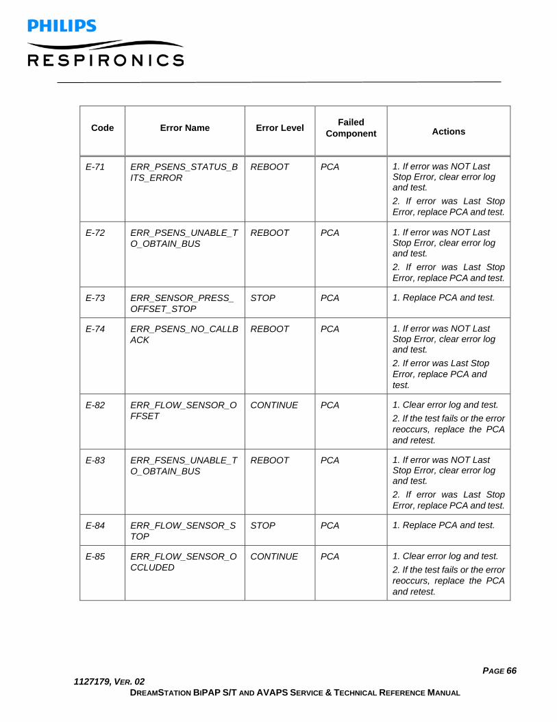
PAGE 66 1127179, VER. 02
DREAMSTATION BIPAP S/T AND AVAPS SERVICE & TECHNICAL REFERENCE MANUAL
Code Error Name Error Level Failed Component Actions
E-71 ERR_PSENS_STATUS_BITS_ERROR
REBOOT PCA 1. If error was NOT Last Stop Error, clear error log and test. 2. If error was Last Stop Error, replace PCA and test.
E-72 ERR_PSENS_UNABLE_TO_OBTAIN_BUS
REBOOT PCA 1. If error was NOT Last Stop Error, clear error log and test. 2. If error was Last Stop Error, replace PCA and test.
E-73 ERR_SENSOR_PRESS_OFFSET_STOP
STOP PCA 1. Replace PCA and test.
E-74 ERR_PSENS_NO_CALLBACK
REBOOT PCA 1. If error was NOT Last Stop Error, clear error log and test. 2. If error was Last Stop Error, replace PCA and test.
E-82 ERR_FLOW_SENSOR_OFFSET
CONTINUE PCA 1. Clear error log and test. 2. If the test fails or the error reoccurs, replace the PCA and retest.
E-83 ERR_FSENS_UNABLE_TO_OBTAIN_BUS
REBOOT PCA 1. If error was NOT Last Stop Error, clear error log and test. 2. If error was Last Stop Error, replace PCA and test.
E-84 ERR_FLOW_SENSOR_STOP
STOP PCA 1. Replace PCA and test.
E-85 ERR_FLOW_SENSOR_OCCLUDED
CONTINUE PCA 1. Clear error log and test. 2. If the test fails or the error reoccurs, replace the PCA and retest.

PAGE 67 1127179, VER. 02
DREAMSTATION BIPAP S/T AND AVAPS SERVICE & TECHNICAL REFERENCE MANUAL
Code Error Name Error Level Failed Component Actions
E-87 ERR_FLOW_SENSOR_BUS
CONTINUE PCA 1. Clear error log and test. 2. If the test fails or the error reoccurs, replace the PCA and retest.
E-93 ERR_RTC_VALUE CONTINUE N/A 1. Clear error log, set the RTC and test. 2. If the test fails or the error reoccurs, replace the PCA and retest.
E-94 ERR_RTC_STOPPED CONTINUE PCA 1. Replace PCA and test.
E-100 ERR_HUMID_NO_HEAT CONTINUE Heater Plate 1. Clear error log and test. 2. Test humidifier separately.
E-101 ERR_HUMID_MAX_TEMP
CONTINUE Heater Plate 1. Clear error log and test. 2. Test humidifier separately.
E-105 ERR_HUMID_AMBIENT_COMM
CONTINUE PCA 1. Clear error log and test. 2. If the test fails or the error reoccurs, replace the PCA and retest.
E-106 ERR_HEATED_TUBE_MAX_TEMP
CONTINUE Heated Tube 1. Clear error log and test. 2. Test humidifier separately.
E-107 ERR_HEATEDTUBE_DISCONNECT
CONTINUE N/A 1. Clear error log and test.
E-108 ERR_HUMIDIFIER_DISCONNECT
CONTINUE N/A 1. Clear error log and test.
E-130 ERR_TASK_WDOG_TIMEOUT
REBOOT PCA 1. If error was NOT Last Stop Error, clear error log and test. 2. If error was Last Stop Error, replace PCA and test.

PAGE 68 1127179, VER. 02
DREAMSTATION BIPAP S/T AND AVAPS SERVICE & TECHNICAL REFERENCE MANUAL
Code Error Name Error Level Failed Component Actions
E-131 ERR_WIN_WDOG_TIMEOUT
ABORT PCA 1. If error was NOT Last Stop Error, clear error log and test. 2. If error was Last Stop Error, replace PCA and test.
E-132 ERR_WIN_WDOG_TEST REBOOT PCA 1. If error was NOT Last Stop Error, clear error log and test. 2. If error was Last Stop Error, replace PCA and test.
E-133 ERR_WIN_WDOG_TEST_RAM
REBOOT PCA 1. If error was NOT Last Stop Error, clear error log and test. 2. If error was Last Stop Error, replace PCA and test.
E-150 ERR_CPU_NMI ABORT PCA 1. Replace PCA and test.
E-151 ERR_CPU_HARD_FAULT ABORT PCA 1. Replace PCA and test.
E-152 ERR_CPU_MEM_MANAGE_FAULT
ABORT PCA 1. Replace PCA and test.
E-153 ERR_CPU_BUS_FAULT ABORT PCA 1. Replace PCA and test.
E-154 ERR_CPU_USAGE_FAULT
ABORT PCA 1. Replace PCA and test.
E-155 ERR_CPU_UNHANDLED_EXCEPTION
ABORT PCA 1. Replace PCA and test.
E-170 ERR_BT_RESET_TX CONTINUE PCA 1. Replace PCA and test.
E-171 ERR_BT_RESET_RX CONTINUE PCA 1. Replace PCA and test.
E-172 ERR_BT_STACK_ERROR
CONTINUE PCA 1. Replace PCA and test.
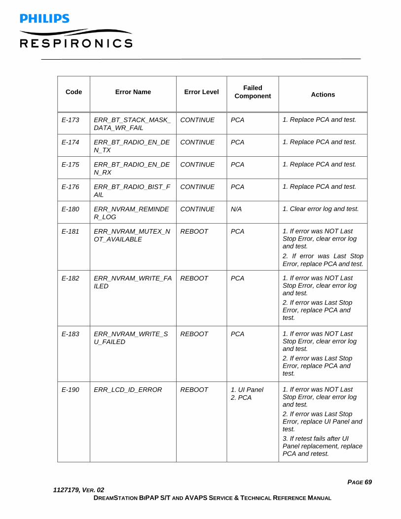
PAGE 69 1127179, VER. 02
DREAMSTATION BIPAP S/T AND AVAPS SERVICE & TECHNICAL REFERENCE MANUAL
Code Error Name Error Level Failed Component Actions
E-173 ERR_BT_STACK_MASK_DATA_WR_FAIL
CONTINUE PCA 1. Replace PCA and test.
E-174 ERR_BT_RADIO_EN_DEN_TX
CONTINUE PCA 1. Replace PCA and test.
E-175 ERR_BT_RADIO_EN_DEN_RX
CONTINUE PCA 1. Replace PCA and test.
E-176 ERR_BT_RADIO_BIST_FAIL
CONTINUE PCA 1. Replace PCA and test.
E-180 ERR_NVRAM_REMINDER_LOG
CONTINUE N/A 1. Clear error log and test.
E-181 ERR_NVRAM_MUTEX_NOT_AVAILABLE
REBOOT PCA 1. If error was NOT Last Stop Error, clear error log and test. 2. If error was Last Stop Error, replace PCA and test.
E-182 ERR_NVRAM_WRITE_FAILED
REBOOT PCA 1. If error was NOT Last Stop Error, clear error log and test. 2. If error was Last Stop Error, replace PCA and test.
E-183 ERR_NVRAM_WRITE_SU_FAILED
REBOOT PCA 1. If error was NOT Last Stop Error, clear error log and test. 2. If error was Last Stop Error, replace PCA and test.
E-190 ERR_LCD_ID_ERROR REBOOT 1. UI Panel 2. PCA
1. If error was NOT Last Stop Error, clear error log and test. 2. If error was Last Stop Error, replace UI Panel and test. 3. If retest fails after UI Panel replacement, replace PCA and retest.

PAGE 70 1127179, VER. 02
DREAMSTATION BIPAP S/T AND AVAPS SERVICE & TECHNICAL REFERENCE MANUAL
Code Error Name Error Level Failed Component Actions
E-191 ERR_ALS_BIST CONTINUE PCA 1. Clear error log and test. 2. If the retest fails or the error reoccurs, replace the PCA and retest.
E-192 ERR_USB_DEVICE_LOST
REBOOT Accessory Module
1. Remove and reinsert the accessory module. 2. If error continues, replace accessory module if pulse oximetry is required.
E-193 ERR_USB_HOST_NO_DEVICE
CONTINUE Accessory Module
1. Remove and reinsert the accessory module. 2. If error continues, replace accessory module if pulse oximetry is required.
E-200 ERR_RTOS_ABORT_ERROR
STOP PCA 1. Replace PCA and test.
E-201 ERR_RTOS_TIMEOUT REBOOT PCA 1. If error was NOT Last Stop Error, clear error log and test. 2. If error was Last Stop Error, replace PCA and test.
E-202 ERR_RTOS_ONE_SHOT_TASK_NOT_STOPPED
REBOOT PCA 1. If error was NOT Last Stop Error, clear error log and test. 2. If error was Last Stop Error, replace PCA and test.
E-210 ERR_PERF_CHECK_MSG_TO
STOP PCA 1. Replace PCA and test.
E-211 ERR_PERF_CHECK_POST_FAIL
STOP PCA 1. Replace PCA and test.

PAGE 71 1127179, VER. 02
DREAMSTATION BIPAP S/T AND AVAPS SERVICE & TECHNICAL REFERENCE MANUAL
Code Error Name Error Level Failed Component Actions
E-220 ERR_MOTOR_ID_TIMEOUT
REBOOT PCA 1. If error was NOT Last Stop Error, clear error log and test. 2. If error was Last Stop Error, replace PCA and test.
E-221 ERR_MOTOR_SHUNT_SAFETY_TIMEOUT
REBOOT PCA 1. If error was NOT Last Stop Error, clear error log and test. 2. If error was Last Stop Error, replace PCA and test.
E-222 ERR_MOTOR_DIV_ZERO CONTINUE N/A 1. Clear error log and retest.
E-223 ERR_LOW_PRESSURE_REGULATION
CONTINUE N/A 1. Load latest software version if not up to date. 2. Clear air path including filter and test. 3. If test fails, replace PCA and retest. 4. If retest fails, replace blower box and retest.
E-224 ERR_HIGH_PRESSURE_REGULATION
CONTINUE N/A 1. If applying negative pressure to the unit remove that first and retest. 2. Load latest software version if not up to date. 3. Clear air path including filter and test. 4. If test fails, replace PCA and retest.
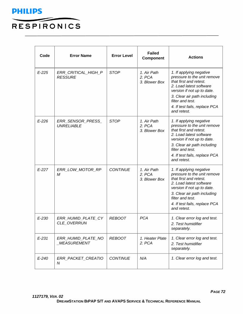
PAGE 72 1127179, VER. 02
DREAMSTATION BIPAP S/T AND AVAPS SERVICE & TECHNICAL REFERENCE MANUAL
Code Error Name Error Level Failed Component Actions
E-225 ERR_CRITICAL_HIGH_PRESSURE
STOP 1. Air Path 2. PCA 3. Blower Box
1. If applying negative pressure to the unit remove that first and retest. 2. Load latest software version if not up to date. 3. Clear air path including filter and test. 4. If test fails, replace PCA and retest.
E-226 ERR_SENSOR_PRESS_UNRELIABLE
STOP 1. Air Path 2. PCA 3. Blower Box
1. If applying negative pressure to the unit remove that first and retest. 2. Load latest software version if not up to date. 3. Clear air path including filter and test. 4. If test fails, replace PCA and retest.
E-227 ERR_LOW_MOTOR_RPM
CONTINUE 1. Air Path 2. PCA 3. Blower Box
1. If applying negative pressure to the unit remove that first and retest. 2. Load latest software version if not up to date. 3. Clear air path including filter and test. 4. If test fails, replace PCA and retest.
E-230 ERR_HUMID_PLATE_CYCLE_OVERRUN
REBOOT PCA 1. Clear error log and test. 2. Test humidifier separately.
E-231 ERR_HUMID_PLATE_NO_MEASUREMENT
REBOOT 1. Heater Plate 2. PCA
1. Clear error log and test. 2. Test humidifier separately.
E-240 ERR_PACKET_CREATION
CONTINUE N/A 1. Clear error log and test.

PAGE 73 1127179, VER. 02
DREAMSTATION BIPAP S/T AND AVAPS SERVICE & TECHNICAL REFERENCE MANUAL
Code Error Name Error Level Failed Component Actions
E-241 ERR_INVALID_COMPLIANCE_SIZE
CONTINUE N/A 1. Clear error log and retest.
E-250 ERR_BAROMETRIC_COMM
CONTINUE PCA 1. Clear error log and test. 2. If the test fails or the error reoccurs, replace the PCA and retest.
E-260 ERR_CIRCUIT_COMP_MODEL_DIV_ZERO_1
CONTINUE N/A
1. Clear error log and test.
E-261 ERR_CIRCUIT_COMP_MODEL_DIV_ZERO_2
CONTINUE N/A
1. Clear error log and test.
E-262 ERR_CIRCUIT_COMP_DRIFT_DIV_ZERO
CONTINUE N/A
1. Clear error log and test.
E-270 ERR_SDC_UPG_FAILED CONTINUE N/A 1. Clear error log and test.
32767 ERR_INVALID REBOOT PCA 1. If error was NOT Last Stop Error, clear error log and test. 2. If error was Last Stop Error, replace PCA and test.
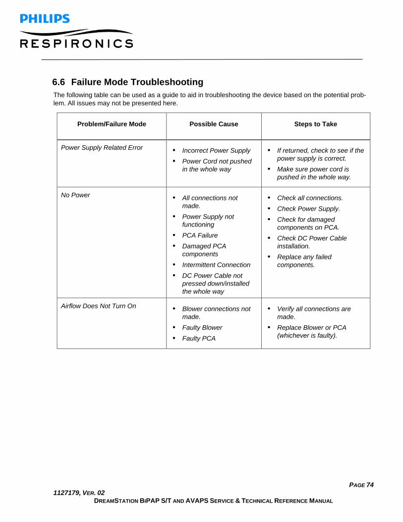
PAGE 74 1127179, VER. 02
DREAMSTATION BIPAP S/T AND AVAPS SERVICE & TECHNICAL REFERENCE MANUAL
6.6 Failure Mode Troubleshooting The following table can be used as a guide to aid in troubleshooting the device based on the potential prob-lem. All issues may not be presented here.
Problem/Failure Mode Possible Cause Steps to Take
Power Supply Related Error • Incorrect Power Supply • Power Cord not pushed
in the whole way
• If returned, check to see if the power supply is correct.
• Make sure power cord is pushed in the whole way.
No Power • All connections not made.
• Power Supply not functioning
• PCA Failure • Damaged PCA
components • Intermittent Connection • DC Power Cable not
pressed down/installed the whole way
• Check all connections. • Check Power Supply. • Check for damaged
components on PCA. • Check DC Power Cable
installation. • Replace any failed
components.
Airflow Does Not Turn On • Blower connections not made.
• Faulty Blower • Faulty PCA
• Verify all connections are made.
• Replace Blower or PCA (whichever is faulty).

PAGE 75 1127179, VER. 02
DREAMSTATION BIPAP S/T AND AVAPS SERVICE & TECHNICAL REFERENCE MANUAL
Problem/Failure Mode Possible Cause Steps to Take
General Noise • Humidifier Seals are damaged or not seated
• Humidifier Back Panel not secure
• Enclosures not secure • Blower Box is cracked • Blower Isolators not
seated • Blower is contaminated • Blower noisy in general • Something fell inside
Blower Box • Too much Blower wire
slack outside of the Blower Box (pulled too tight - causing vibration)
• Make sure all Seals are seated.
• Make sure PCA is aligned on seals.
• Make sure enclosures are secure.
• Check for any component damage.
• Check for loose components. • Check Blower wire length
outside of Blower Box (should measure approx. 9.5 inches).
• Replace any failed/damaged component.
Whistling Noise from Humidifier • Humidifier Seals are damaged or not seated
• Humidifier Back Panel not seated
• Wire guard loose • Tank is cracked • Dry Box not seated • Flip Lid latch damaged or
not latching well • PAP and Humidifier not
fully connected
• Make sure all Seals and components are seated.
• Check for any component damage.
• Replace damaged components.
Whistling Noise from PAP Device • PAP and Humidifier not fully connected
• PAP Enclosure separated.
• Blower noisy
• Check all connections. • Replace blower if noisy.

PAGE 76 1127179, VER. 02
DREAMSTATION BIPAP S/T AND AVAPS SERVICE & TECHNICAL REFERENCE MANUAL
Problem/Failure Mode Possible Cause Steps to Take
Airflow is Warm • The air filters may be dirty
• The device may be operating in direct sunlight or near a heater
• Heater Plate or Heated Tube settings are high
• Make sure there is no debris in the filters.
• Make sure the device is properly ventilated.
• Keep the device away from direct sunlight and heating equipment.
• Check and record Heater Plate and Heated Tube settings.
Unit Shuts Off • Auto Off feature is enabled and high leak exists for a duration that triggers Auto Off
• System Issue • Power Supply faulty
• Examine Auto Off setting in provider mode.
• Check Power Supply. • Check all connections. • Run device for extended
period of time is necessary. • Replace any failed
component.
Dial Does Not Work • The UI ribbon cable is damaged or not seated.
• Check Encoder ribbon cable. • Remove and reinsert Encoder
ribbon cable. • Replace UI Panel if problem
still occurs.
Therapy Button Does Not Work • Damage to PCA • Damage to mechanical
buttons • Therapy Button damaged • Contamination • User perception
• Check for physical damage or enclosure separation.
• Replace damaged component(s).
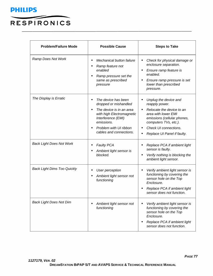
PAGE 77 1127179, VER. 02
DREAMSTATION BIPAP S/T AND AVAPS SERVICE & TECHNICAL REFERENCE MANUAL
Problem/Failure Mode Possible Cause Steps to Take
Ramp Does Not Work • Mechanical button failure • Ramp feature not
enabled • Ramp pressure set the
same as prescribed pressure
• Check for physical damage or enclosure separation.
• Ensure ramp feature is enabled.
• Ensure ramp pressure is set lower than prescribed pressure.
The Display is Erratic • The device has been dropped or mishandled
• The device is in an area with high Electromagnetic Interference (EMI) emissions.
• Problem with UI ribbon cables and connections.
• Unplug the device and reapply power.
• Relocate the device to an area with lower EMI emissions (cellular phones, computers TVs, etc.).
• Check UI connections. • Replace UI Panel if faulty.
Back Light Does Not Work • Faulty PCA • Ambient light sensor is
blocked.
• Replace PCA if ambient light sensor is faulty.
• Verify nothing is blocking the ambient light sensor.
Back Light Dims Too Quickly • User perception • Ambient light sensor not
functioning
• Verify ambient light sensor is functioning by covering the sensor hole on the Top Enclosure.
• Replace PCA if ambient light sensor does not function.
Back Light Does Not Dim • Ambient light sensor not functioning
• Verify ambient light sensor is functioning by covering the sensor hole on the Top Enclosure.
• Replace PCA if ambient light sensor does not function.
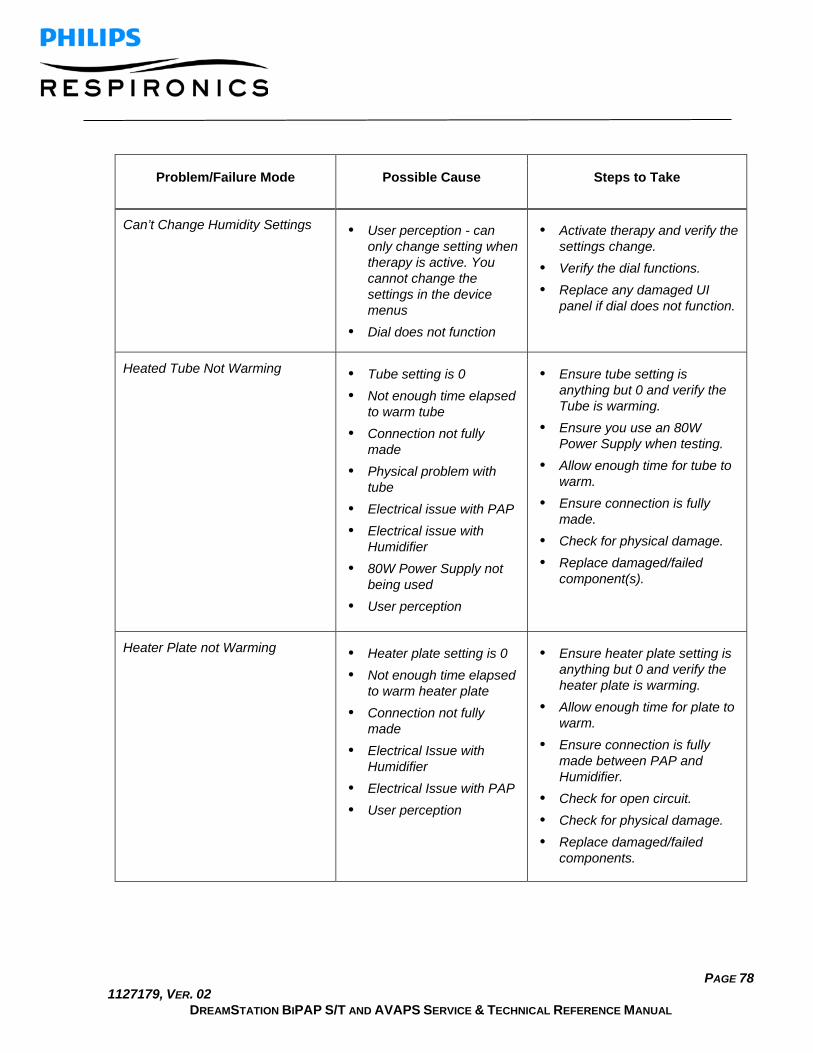
PAGE 78 1127179, VER. 02
DREAMSTATION BIPAP S/T AND AVAPS SERVICE & TECHNICAL REFERENCE MANUAL
Problem/Failure Mode Possible Cause Steps to Take
Can’t Change Humidity Settings • User perception - can only change setting when therapy is active. You cannot change the settings in the device menus
• Dial does not function
• Activate therapy and verify the settings change.
• Verify the dial functions. • Replace any damaged UI
panel if dial does not function.
Heated Tube Not Warming • Tube setting is 0 • Not enough time elapsed
to warm tube • Connection not fully
made • Physical problem with
tube • Electrical issue with PAP • Electrical issue with
Humidifier • 80W Power Supply not
being used • User perception
• Ensure tube setting is anything but 0 and verify the Tube is warming.
• Ensure you use an 80W Power Supply when testing.
• Allow enough time for tube to warm.
• Ensure connection is fully made.
• Check for physical damage. • Replace damaged/failed
component(s).
Heater Plate not Warming • Heater plate setting is 0 • Not enough time elapsed
to warm heater plate • Connection not fully
made • Electrical Issue with
Humidifier • Electrical Issue with PAP • User perception
• Ensure heater plate setting is anything but 0 and verify the heater plate is warming.
• Allow enough time for plate to warm.
• Ensure connection is fully made between PAP and Humidifier.
• Check for open circuit. • Check for physical damage. • Replace damaged/failed
components.

PAGE 79 1127179, VER. 02
DREAMSTATION BIPAP S/T AND AVAPS SERVICE & TECHNICAL REFERENCE MANUAL
Problem/Failure Mode Possible Cause Steps to Take
Tank Runs Out of Water • Settings are at max for an unsuitable environment
• User has high mask leak • Tank is leaking
• Examine Humidifier settings. • Check for damage to the
Tank.
Humidifier Lid Won’t Latch/Open • Latch is damaged • Enclosure is damaged
• Check for component damage.
• Replace any damaged components.
Doesn’t Make a Call • Interface between PAP and Modem not functioning
• Verify the PAP recognizes the Modem in the My Provider menu.
• Attempt to make a call and verify it was successful.
SD Card Error • SD Card corrupted • Problem with PCA
• Eject and reinsert the SD Card.
• If error still occurs, check to see if you get an error with a test SD Card that works properly.
• Clear any errors on the PCA. • If error is not duplicated,
replace SD Card. • If same error occurs with a
properly working SD Card and after PCA errors are cleared, replace the PCA.
Can’t Read SD Card Data • A previous version of Encore is being used
• SD Card corrupted
• Ensure Encore is up-to-date. • Use Encore or similar
software to verify SD Card data can be read.

PAGE 80 1127179, VER. 02
DREAMSTATION BIPAP S/T AND AVAPS SERVICE & TECHNICAL REFERENCE MANUAL
6.7 Device Alarms There are two types of alarms:
• High priority - Require immediate response by the operator. • Medium priority - Require prompt response by the operator.
When an alarm condition occurs: • The audio pause icon appears and the control dial LED indicator lights. • The audible alarm sounds. • A message appears on the screen describing the type of alarm.
6.8 Device Alerts Alerts are informational and confirmation messages that notify you of conditions that require attention but are not alarm conditions. Most alerts do not appear while therapy is being delivered. The different types of alerts are:
• Status - Message appears on the screen. • Notification - Message appears on the screen and Therapy button LED flashes. • Alert - Message appears on the screen, Therapy button LED flashes, and audible sound
beeps once while alert is displayed.
6.9 Alarm and Alert LED Indicators
Red flashing alarm LED When a high priority alarm is de-tected, the audio pause icon (1) and control dial LED (2) flash red.
Yellow flashing alarm LED When a medium priority alarm is detected, the audio pause icon (1) and control dial LED (2) flash yellow.
Flashing Therapy button LED When an alert or notification message appears on the screen, the Therapy button LED flashes. If the alert occurs while therapy is being delivered, the alert or notification will appear on the screen, but the LED will not flash.

PAGE 81 1127179, VER. 02
DREAMSTATION BIPAP S/T AND AVAPS SERVICE & TECHNICAL REFERENCE MANUAL
6.10 Alarm and Alert Audible Indicators An audible indicator sounds when any of the following occurs:
• A device inoperative condition occurs • The blower is on and a power failure occurs • An alarm condition occurs • An alert message appears on the screen
Alarm/Alert Type Audible Indicator
Device Inoperative When a device inoperative alarm occurs, a continuous audible indicator sounds.
Power failure When a power failure occurs, a series of beeps sounds in a 1 beep pat-tern, repeating one second on, then one second off.
• •
High priority When a high priority alarm is active, a series of beeps sounds in the fol-lowing pattern, which is repeated twice: 3 beeps, a pause, and then 2 more beeps. This indicator continues until the cause of the alarm is cor-rected or the audible alarm is silenced.
• • • • • • • • • •
Medium priority When a medium priority alarm is active, a series of beeps sounds in a 3-beep pattern. This pattern repeats until the cause of the alarm is cor-rected or the audible alarm is silenced. T
• • •
Alerts When an alert appears on screen, a brief, 1-beep audible indicator sounds.
•

PAGE 82 1127179, VER. 02
DREAMSTATION BIPAP S/T AND AVAPS SERVICE & TECHNICAL REFERENCE MANUAL
6.11 Silencing an Alarm You can temporarily silence an alarm by pressing the control dial. The alarm is silenced for 60 seconds and then sounds again if the cause of the alarm has not been corrected. If another alarm occurs while the silence period is active, the audible alarm portion of the new alarm will not sound until the silence period expires. When the silence period expires, the alarm’s audible alarm is reactivated if the alarm condition has not be cor-rected.
6.12 Alarm Message Screens When an alarm message is activated, an alarm screen is displayed, showing the text or icon specific to the most recent, highest priority alarm.
Pressing the control dial once will silence the audible alarm. Press the control dial again to remove the alarm screen from the display. Resetting the alarm allows you to return to the previous screen. If multiple alarms occur during the same period of time, the alarm screen will display the higher priority alarm (higher priority alarms take precedence over lower priority alarms).
6.13 What to Do When an Alarm Occurs Complete the following steps when an alarm occurs:
1. Listen to the audible alarm and look at the alarm indicators and whether the LED is solid or flashing. 2. Look at the display to check the alarm message that appears on-screen and whether it is red or yel-
low. 3. Press the control dial to temporarily silence the audible alarm. Or, press the control dial twice to ac-
knowledge and remove the alarm from the screen. In case of loss of power, use the control dial to both silence and terminate the alarm.
4. Look up the alarm in the alarm descriptions in this chapter to determine the source of the alarm and the appropriate action.

PAGE 83 1127179, VER. 02
DREAMSTATION BIPAP S/T AND AVAPS SERVICE & TECHNICAL REFERENCE MANUAL
6.14 Alarm Summary Table The following table summarizes the alarms. See Alarm and alert LED indicators and Alarm and alert audi-ble indicators earlier in this chapter for LED and audible indicators for each alarm type.
Alarm Priority Device Action User Action
High Operates This alarm occurs when the calculated minute ventilation is less than or equal to the alarm setting. Press the con-trol dial to silence the alarm. Press the control dial again to acknowledge and remove the alarm from the screen.
High Operates This alarm occurs when the patient has not triggered a breath within the time speci-fied in the apnea alarm set-ting. The device continues to operate. The alarm will auto-matically terminate when two consecutive patient breaths are detected that meet the apnea alarm time setting.
Press the control dial to si-lence the alarm. Press the control dial again to acknowledge and remove the alarm from the screen.
Medium Operates Only enabled if AVAPS ther-apy feature is enabled. This alarm occurs when the de-vice is unable to reach the target tidal volume setting. Press the control dial to si-lence the alarm. Press the control dial again to acknowledge and remove the alarm from the screen.
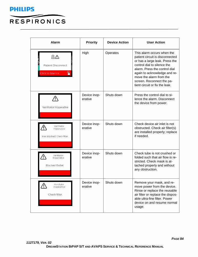
PAGE 84 1127179, VER. 02
DREAMSTATION BIPAP S/T AND AVAPS SERVICE & TECHNICAL REFERENCE MANUAL
Alarm Priority Device Action User Action
High Operates This alarm occurs when the patient circuit is disconnected or has a large leak. Press the control dial to silence the alarm. Press the control dial again to acknowledge and re-move the alarm from the screen. Reconnect the pa-tient circuit or fix the leak.
Device inop-erative
Shuts down Press the control dial to si-lence the alarm. Disconnect the device from power.
Device inop-erative
Shuts down Check device air inlet is not obstructed. Check air filter(s) are installed properly; replace if needed.
Device inop-erative
Shuts down Check tube is not crushed or folded such that air flow is re-stricted. Check mask is at-tached properly and without any obstruction.
Device inop-erative
Shuts down Remove your mask, and re-move power from the device. Rinse or replace the reusable air filter or replace the dispos-able ultra-fine filter. Power device on and resume normal usage.
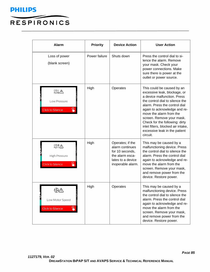
PAGE 85 1127179, VER. 02
DREAMSTATION BIPAP S/T AND AVAPS SERVICE & TECHNICAL REFERENCE MANUAL
Alarm Priority Device Action User Action
Loss of power
(blank screen)
Power failure Shuts down Press the control dial to si-lence the alarm. Remove your mask. Check your power connections. Make sure there is power at the outlet or power source.
High Operates This could be caused by an excessive leak, blockage, or a device malfunction. Press the control dial to silence the alarm. Press the control dial again to acknowledge and re-move the alarm from the screen. Remove your mask. Check for the following: dirty inlet filters, blocked air intake, excessive leak in the patient circuit.
High Operates; if the alarm continues for 10 seconds, the alarm esca-lates to a device inoperable alarm.
This may be caused by a malfunctioning device. Press the control dial to silence the alarm. Press the control dial again to acknowledge and re-move the alarm from the screen. Remove your mask, and remove power from the device. Restore power.
High Operates This may be caused by a malfunctioning device. Press the control dial to silence the alarm. Press the control dial again to acknowledge and re-move the alarm from the screen. Remove your mask, and remove power from the device. Restore power.

PAGE 86 1127179, VER. 02
DREAMSTATION BIPAP S/T AND AVAPS SERVICE & TECHNICAL REFERENCE MANUAL
Alarm Priority Device Action User Action
Medium Operates Press the control dial again to acknowledge and remove the alarm from the screen. Re-move your mask. Remove power from the device. Con-firm a compatible Philips Respironics power supply is attached. Switch to compati-ble power supply, if needed. If battery is being used, en-sure battery is adequately charged.

PAGE 87 1127179, VER. 02
DREAMSTATION BIPAP S/T AND AVAPS SERVICE & TECHNICAL REFERENCE MANUAL
6.15 Alert Summary Table The following table summarizes the alerts. See Alarm and alert LED indicators and Alarm and alert audi-ble indicators for LED and audible indicators for each alert type. The screen below is an example of an alert screen. The icons shown in the table below appear on the top of each alert screen.
Alert Icon Priority Description User Action
Data Activity: Do not remove SD card.
Status SD card read/write underway.
No action needed.
Change Accepted
Status Confirms acceptance
of prescription change or device upgrade.
No action needed.
Oximetry: Good Connec-tion (icon only)
Status Displays on the ther-apy screen when the blower is on and 3 sec-onds of good connec-tion is detected. Ap-pears at the beginning of therapy. This screen will not display again if the oximetry sensor is removed and reapplied unless therapy is stopped and restarted.
No action needed.
Pair?: 123456 Yes/No
Status Prompts to accept or decline pairing to a Bluetooth compatible device. This device can be identified by the digits displayed.
Rotate control dial to accept pairing (Yes), or decline (No), then press control dial to confirm selection.

PAGE 88 1127179, VER. 02
DREAMSTATION BIPAP S/T AND AVAPS SERVICE & TECHNICAL REFERENCE MANUAL
Alert Icon Priority Description User Action
Pair? Yes/No
Status Prompts to accept or decline pairing to a Bluetooth compatible device.
Rotate the control dial to accept pairing (Yes), or decline (No), then press the control dial to confirm selection. Selecting Yes opens the Bluetooth passkey screen.
Flow Sensor Error: Limited Therapy
Notification
Flow sensor malfunction.
Press the control dial to acknowledge and clear the message. Disconnect the device from power. Immediately remove patient from ventilator and connect them to alternate source of ventilation.
SD Card Removed.
Notification or Alert 2
Indicates SD card has been removed from therapy device and not reinserted before the start of the current therapy session.
Reinsert SD card, or click to clear alert.
Oximetry: Good Study (icon only)
Notification After exiting therapy,
the therapy device will display the Good Oxi-metry pop-up screen if the oximetry sensor maintained a good con-nection for at least 4 consecutive hours within a 24 hour win-dow with breaks in ther-apy no greater than 1 hour each.
Press Control Dial to acknowledge and clear the message.
SD Card Error: Remove and Reinsert
Notification SD card error detected.
Remove SD card and reinsert. If alert continues to occur, replace with another card.
SD Card Full.
Notification SD card is full. Remove SD card and replace with a new card.
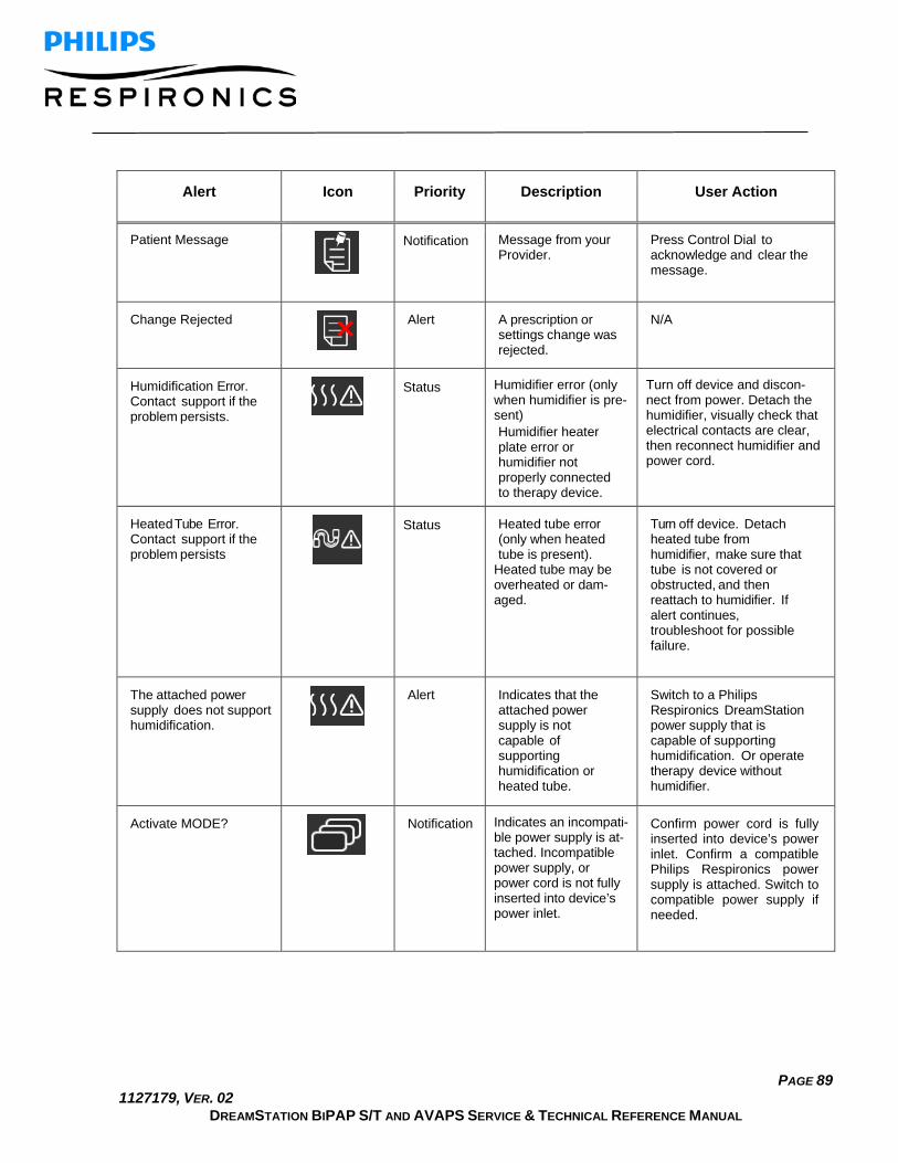
PAGE 89 1127179, VER. 02
DREAMSTATION BIPAP S/T AND AVAPS SERVICE & TECHNICAL REFERENCE MANUAL
Alert Icon Priority Description User Action
Patient Message
Notification Message from your Provider.
Press Control Dial to acknowledge and clear the message.
Change Rejected
Alert A prescription or settings change was rejected.
N/A
Humidification Error. Contact support if the problem persists.
Status Humidifier error (only when humidifier is pre-sent) Humidifier heater plate error or humidifier not properly connected to therapy device.
Turn off device and discon-nect from power. Detach the humidifier, visually check that electrical contacts are clear, then reconnect humidifier and power cord.
Heated Tube Error. Contact support if the problem persists
Status Heated tube error (only when heated tube is present).
Heated tube may be overheated or dam-aged.
Turn off device. Detach heated tube from humidifier, make sure that tube is not covered or obstructed, and then reattach to humidifier. If alert continues, troubleshoot for possible failure.
The attached power supply does not support humidification.
Alert Indicates that the attached power supply is not capable of supporting humidification or heated tube.
Switch to a Philips Respironics DreamStation power supply that is capable of supporting humidification. Or operate therapy device without humidifier.
Activate MODE?
Notification Indicates an incompati-ble power supply is at-tached. Incompatible power supply, or power cord is not fully inserted into device’s power inlet.
Confirm power cord is fully inserted into device’s power inlet. Confirm a compatible Philips Respironics power supply is attached. Switch to compatible power supply if needed.

PAGE 90 1127179, VER. 02
DREAMSTATION BIPAP S/T AND AVAPS SERVICE & TECHNICAL REFERENCE MANUAL
Alert Icon Priority Description User Action
Check Power
Notification Indicates an incompati-ble power supply is at-tached. Incompatible power supply, or power cord is not fully inserted into device’s power inlet.
Confirm power cord is full inserted into device’s power inlet. Confirm a compatible Philips Respironics power supply is attached. Switch to compatible power supply if needed.
Busy
Status Displayed when the device is temporarily inaccessible due to data communication.
No action needed.
Three Night Summary N/A Status Displays last 3 nights of hourly use.
Press control dial to acknowledge and clear the screen. Otherwise message times out after 30 seconds.
Check Mask Fit N/A Status Displayed when Check Mask Fit function is enabled from Patient Menu.
This alert can be cleared by pressing the control dial. Otherwise, it will time out after 60 seconds.
Loading Language and Rebooting
Status Displayed when a new language is selected from the menu.
No action needed. Times out when complete.
Accessory Unsupported
Notification Warning! If this screen appears, you have an accessory connected to the device that could impact therapy.
Detach the unsupported accessory.

PAGE 91 1127179, VER. 02
DREAMSTATION BIPAP S/T AND AVAPS SERVICE & TECHNICAL REFERENCE MANUAL
Chapter 7. Repair & Replacement This Chapter illustrates the names and locations of the replaceable components in the DreamStation devices. Prior to executing the repair and replacement procedures, the troubleshooting procedures must first be exe-cuted. Refer to Chapter 6 for troubleshooting procedures.
IMPORTANT NOTE
The device must be tested after any repairs are made. Refer to Chapter 9 for details on testing the device.
WARNING
To prevent electrical shock, disconnect the electrical supply before attempting to make any repairs to these devices.
CAUTION
Components used in this device are subject to damage from static electricity. Repairs made to this device must be performed only in an anti-static, Electro-Static Discharge (ESD) protected environment.
CAUTION
Do not attempt to power on the PCA/device without all connections being made. Otherwise, false errors or failure detections could occur. The device must be fully assembled in order to properly assess any functionality.

PAGE 92 1127179, VER. 02
DREAMSTATION BIPAP S/T AND AVAPS SERVICE & TECHNICAL REFERENCE MANUAL
7.1 Replacement Part (RP) Kits
DESCRIPTION RP KIT NUMBER
Accessory Module Flip Door 1115485
SD Cover Flip Door 1115542
Upper Enclosure (Includes Keypad) 1115486
UI Panel Assembly, BiPAP S/T 1130519
UI Panel Assembly, BiPAP AVAPS 1130520
UI Knob 1130437
PCA, BiPAP S/T 25 – IN, DE, CN 1130523
PCA, BiPAP S/T 30 – US, FR, BR 1130734
PCA, BiPAP S/T 30 – IN, DE, CN 1130737
PCA, BiPAP AVAPS 25 - IN 1130524
PCA, BiPAP AVAPS 30 – US 1130758
PCA, BiPAP AVAPS 30 – CA, IN, DE, FR, CN, BR
1130759
PCA, BiPAP AVAPS 30 AE – IN, JP, CN 1130760
Pressure Sensor Seal 1121527
Flow Sensor Seal 1115484
Blower Upper Cap 1115481
Blower Box Assembly 1121548
Blower Assembly, Moog 1130521
Blower Isolators, Moog 1121551
Blower Outlet Seal 1121553
DC Power Cable 1121554
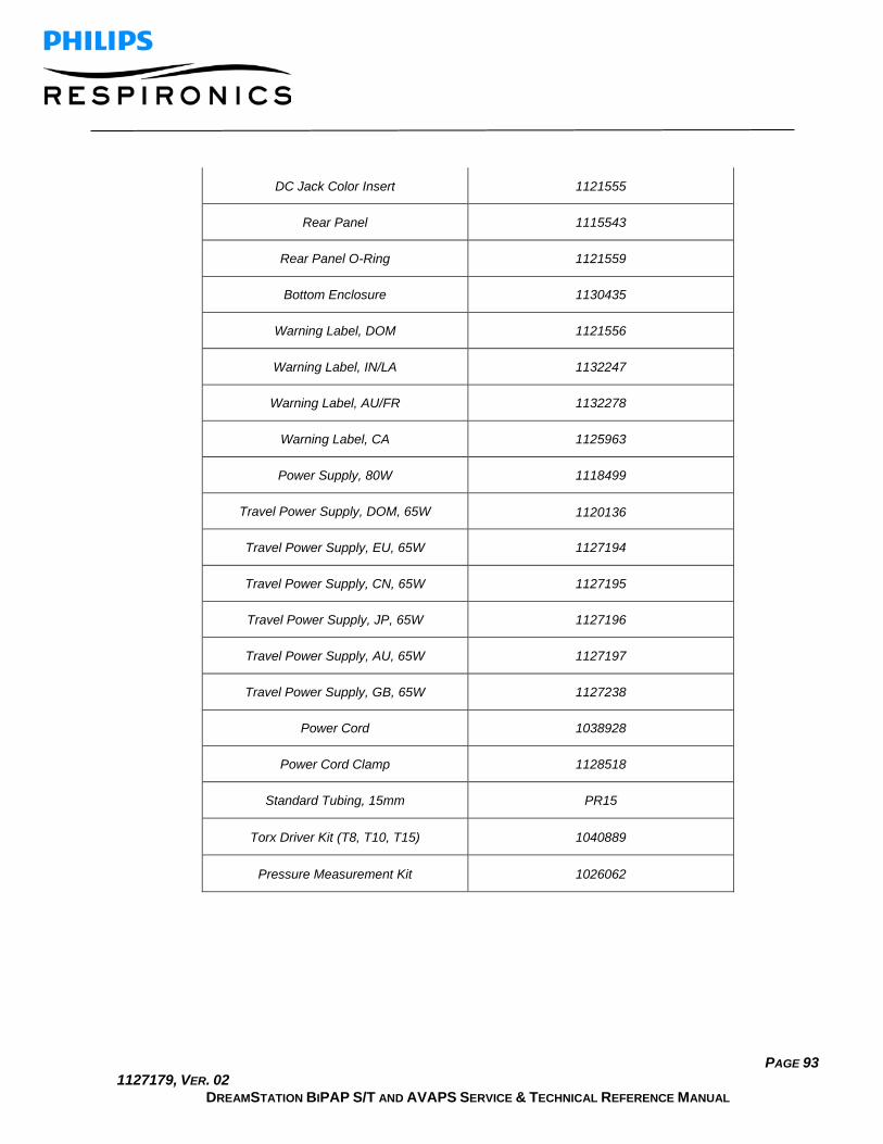
PAGE 93 1127179, VER. 02
DREAMSTATION BIPAP S/T AND AVAPS SERVICE & TECHNICAL REFERENCE MANUAL
DC Jack Color Insert 1121555
Rear Panel 1115543
Rear Panel O-Ring 1121559
Bottom Enclosure 1130435
Warning Label, DOM 1121556
Warning Label, IN/LA 1132247
Warning Label, AU/FR 1132278
Warning Label, CA 1125963
Power Supply, 80W 1118499
Travel Power Supply, DOM, 65W 1120136
Travel Power Supply, EU, 65W 1127194
Travel Power Supply, CN, 65W 1127195
Travel Power Supply, JP, 65W 1127196
Travel Power Supply, AU, 65W 1127197
Travel Power Supply, GB, 65W 1127238
Power Cord 1038928
Power Cord Clamp 1128518
Standard Tubing, 15mm PR15
Torx Driver Kit (T8, T10, T15) 1040889
Pressure Measurement Kit 1026062

PAGE 94 1127179, VER. 02
DREAMSTATION BIPAP S/T AND AVAPS SERVICE & TECHNICAL REFERENCE MANUAL
7.2 Replacement Instructions Prior to executing repair and replacement procedures, device troubleshooting must be performed. Refer to Chapter 6 for troubleshooting procedures.
Replacing the Accessory Module and SD Flip Doors
Kit Included in Kit
Tools Required
Accessory Module Flip Door
• Accessory Module Flip Door
• None
SD Cover Flip Door • Accessory Cover Flip Door
To remove the Flip Doors:
1. Squeeze the Flip Door standoffs inward and pull the cover away from the device. 2. Repeat on other side.
To install the Flip Doors:
1. Place the Flip Door standoffs back into the holes on the device. 2. Repeat on other side. 3. Verify the Doors are fully seated.
Note: The cutout on the Flip Doors should be towards the back of the device.
Standoffs

PAGE 95 1127179, VER. 02
DREAMSTATION BIPAP S/T AND AVAPS SERVICE & TECHNICAL REFERENCE MANUAL
Replacing the SD Card To remove the SD Card:
1. Press the SD Card in to release. 2. Pull the SD Card out of the device.
To install the SD Card: 1. Slide the SD Card into the slot until it locks into place.
Replacing the Upper Enclosure/Keypad:
Kit Included in Kit Tools Required
Upper Enclosure Assembly • Upper Enclosure • Keypad • # 4 x 1/2” screws (qty
2)
• Torx Screwdriver (T10 is recommended)
To remove the Upper Enclosure/Keypad: 1. Remove the Flip Doors (refer to previous section). 2. Remove the two # 4 x 1/2” screws that secure the Upper Enclosure to the Bottom Enclosure using a
T-10 Torx driver (refer to illustration below). 3. Pull the Upper Enclosure off the device.

PAGE 96 1127179, VER. 02
DREAMSTATION BIPAP S/T AND AVAPS SERVICE & TECHNICAL REFERENCE MANUAL
To install the Upper Enclosure/Keypad: 1. Align and snap the Upper Enclosure into place. 2. Secure the Upper Enclosure to the Bottom Enclosure using the two # 4 x 1/2” (torque to 6 IN-LB). 3. Install the Keypad on the Upper Enclosure as shown in Figure 6-3 above, and verify it is fully seated. 4. Assemble the remainder of the device as instructed in the previous section.
Torque screws to 6 IN-LB when installing Upper Enclosure
Verify Top is fully seated
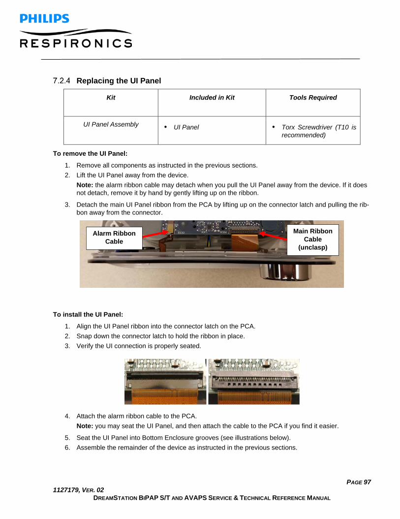
PAGE 97 1127179, VER. 02
DREAMSTATION BIPAP S/T AND AVAPS SERVICE & TECHNICAL REFERENCE MANUAL
Replacing the UI Panel
Kit Included in Kit
Tools Required
UI Panel Assembly • UI Panel • Torx Screwdriver (T10 is recommended)
To remove the UI Panel: 1. Remove all components as instructed in the previous sections. 2. Lift the UI Panel away from the device. Note: the alarm ribbon cable may detach when you pull the UI Panel away from the device. If it does
not detach, remove it by hand by gently lifting up on the ribbon.
3. Detach the main UI Panel ribbon from the PCA by lifting up on the connector latch and pulling the rib-bon away from the connector.
To install the UI Panel: 1. Align the UI Panel ribbon into the connector latch on the PCA. 2. Snap down the connector latch to hold the ribbon in place. 3. Verify the UI connection is properly seated.
4. Attach the alarm ribbon cable to the PCA.
Note: you may seat the UI Panel, and then attach the cable to the PCA if you find it easier.
5. Seat the UI Panel into Bottom Enclosure grooves (see illustrations below). 6. Assemble the remainder of the device as instructed in the previous sections.
Alarm Ribbon Cable
Main Ribbon Cable
(unclasp)

PAGE 98 1127179, VER. 02
DREAMSTATION BIPAP S/T AND AVAPS SERVICE & TECHNICAL REFERENCE MANUAL
GOOD BAD GOOD BAD
Replacing the PCA
Kit Included in Kit Tools Required
PCA • PCA • # 4 x 1/2” screws (qty 2)
• Torx Screwdriver (T10 is recommended)
To remove the PCA: 1. Remove all components as instructed in the previous sections. 2. Remove the two # 4 x 1/2” screws that secure the PCA to the Blower Cap using a T-10 Torx driver. 3. Lift the PCA up away from the device. 4. Disconnect the DC Connector and Blower Connector from the PCA.

PAGE 99 1127179, VER. 02
DREAMSTATION BIPAP S/T AND AVAPS SERVICE & TECHNICAL REFERENCE MANUAL
To install the PCA: 1. Connect the DC and Blower Connectors to the PCA Connectors. 2. Seat the PCA onto the Blower Cap standoff and screw bosses, ensuring to position the Humidifier
Connector located on the PCA into the groove of the Rear Panel, and positioning the Flow and Pres-sure Sensors into the Seals (refer to the illustrations below).
3. Secure the PCA with the two # 4 x 1/2” screws (torque to 2.5 IN-LB). 4. Assemble the remainder of the device as instructed in the previous sections.

PAGE 100 1127179, VER. 02
DREAMSTATION BIPAP S/T AND AVAPS SERVICE & TECHNICAL REFERENCE MANUAL
CAUTION
The PCA’s Flow and Pressure Sensors must be in proper alignment with the Seals. Otherwise, the device will not operate properly.
Align humidifier connector into Rear Panel groove
Align screw bosses Align standoff
Underside of PCA: Position Flow and Pres-sure Sensors into Seals
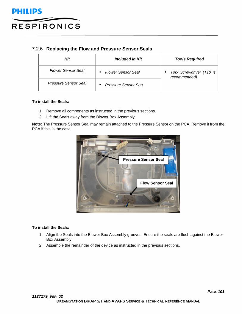
PAGE 101 1127179, VER. 02
DREAMSTATION BIPAP S/T AND AVAPS SERVICE & TECHNICAL REFERENCE MANUAL
Replacing the Flow and Pressure Sensor Seals
Kit Included in Kit Tools Required
Flower Sensor Seal • Flower Sensor Seal • Torx Screwdriver (T10 is recommended)
Pressure Sensor Seal • Pressure Sensor Sea
To install the Seals:
1. Remove all components as instructed in the previous sections. 2. Lift the Seals away from the Blower Box Assembly.
Note: The Pressure Sensor Seal may remain attached to the Pressure Sensor on the PCA. Remove it from the PCA if this is the case.
To install the Seals: 1. Align the Seals into the Blower Box Assembly grooves. Ensure the seals are flush against the Blower
Box Assembly. 2. Assemble the remainder of the device as instructed in the previous sections.
Pressure Sensor Seal
Flow Sensor Seal

PAGE 102 1127179, VER. 02
DREAMSTATION BIPAP S/T AND AVAPS SERVICE & TECHNICAL REFERENCE MANUAL
Replacing the Blower Upper Cap
Kit Included in Kit Tools Required
Blower Upper Cap • Blower Upper Cap • # 4 x 1/2” screws (qty 4)
• Torx Screwdriver (T10 is recommended)
• Flathead Screwdriver
To remove the Blower Upper Cap: 1. Remove all components as instructed in the previous sections 2. Remove the four # 4 x 1/2” screws holding the Blower Cap to the Blower Box Assembly. 3. Using a small flathead screwdriver, carefully pry the Blower Cap off of the Blower Box Assembly
around the Blower Cap chimney as to not damage the Blower Cap seal.
CAUTION
Damage can occur to the seal on the underside of the Blower Upper Cap if prying in the wrong spots. Be sure to pry the Cap off only at the Chimney (refer to the Figure below).
Torque screws to 2.5 IN-LB when installing Blower Cap
Pry off Blower Cap around Chimney edge
Blower Cap Chimney

PAGE 103 1127179, VER. 02
DREAMSTATION BIPAP S/T AND AVAPS SERVICE & TECHNICAL REFERENCE MANUAL
To install the Blower Upper Cap: 1. Align the Blower Cap with the screw holes on the Blower Box Assembly, verifying the Blower Cap is
fully seated. 2. Secure the Blower Cap to the Blower Box Assembly using the four # 4 x 1/2” screws (torque to 2.5
IN-LB). 3. Assemble the remainder of the device as instructed in the previous sections.
CAUTION
Ensure the Blower Cap is seated properly.
Seated (Good) Not seated (Bad)

PAGE 104 1127179, VER. 02
DREAMSTATION BIPAP S/T AND AVAPS SERVICE & TECHNICAL REFERENCE MANUAL
Replacing the Blower, Blower Box Assembly, and Rear Panel
Kit Included in Kit Tools Required
Blower Assembly, Moog • Blower • Torx Screwdriver (T10 is recommended)
Blower Box Assembly • Blower Box Assembly
Rear Panel Assembly • Rear Panel • Rear Panel O-Ring
To remove the Blower, Blower Box Assembly and Rear Panel:
1. Remove all components as instructed in the previous sections. 2. Remove the two # 4 x 1/2” screws holding the Blower Box Assembly to the Bottom Enclosure.
3. Lift the back end of the Blower Box Assembly slightly out of the Bottom Enclosure and carefully pull the Rear Panel from the Blower Box Assembly by pulling it out of the grooves.
4. Remove the DC Connector ferrite from the Rear Panel (refer to the illustration below). 5. Lift the Blower Box Assembly out of the Bottom Enclosure.
Torque screws to 6 IN-LB when in-stalling the Blower Box Assembly
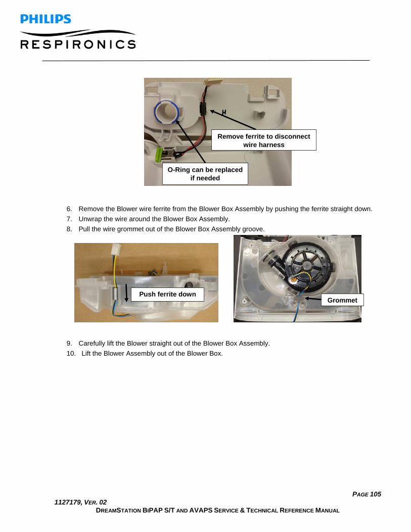
PAGE 105 1127179, VER. 02
DREAMSTATION BIPAP S/T AND AVAPS SERVICE & TECHNICAL REFERENCE MANUAL
6. Remove the Blower wire ferrite from the Blower Box Assembly by pushing the ferrite straight down. 7. Unwrap the wire around the Blower Box Assembly. 8. Pull the wire grommet out of the Blower Box Assembly groove.
9. Carefully lift the Blower straight out of the Blower Box Assembly. 10. Lift the Blower Assembly out of the Blower Box.
Remove ferrite to disconnect wire harness
O-Ring can be replaced if needed
Push ferrite down Grommet

PAGE 106 1127179, VER. 02
DREAMSTATION BIPAP S/T AND AVAPS SERVICE & TECHNICAL REFERENCE MANUAL
To install the Blower, Blower Box Assembly and Rear Panel:
1. Position the Blower inside the Blower Box Assembly so that the Blower Outlet Seal and Blower Isolators are aligned in their grooves.
CAUTION
• The Blower with the Isolators attached should be rested inside the Blower Box. Do not press down on the Blower after installation.
2. Insert Grommet into slot. 3. Set Blower wire length to approximately 9.5 in from the outside of the Blower Box Assembly.
Blower Outlet Seal Blower Isolators
Ensure wires are routed as shown
Grommet
Wire length approx. 9.5 inches from this point

PAGE 107 1127179, VER. 02
DREAMSTATION BIPAP S/T AND AVAPS SERVICE & TECHNICAL REFERENCE MANUAL
4. Verify the Blower Outlet Seal is properly seated.
GOOD – Seated BAD – Not Seated
5. Route the Blower wires as shown below.
Seat in groove

PAGE 108 1127179, VER. 02
DREAMSTATION BIPAP S/T AND AVAPS SERVICE & TECHNICAL REFERENCE MANUAL
6. Snap DC Cable ferrite into groove on Rear Panel.
Slide ferrite up to the top of the groove
Snap ferrite into groove

PAGE 109 1127179, VER. 02
DREAMSTATION BIPAP S/T AND AVAPS SERVICE & TECHNICAL REFERENCE MANUAL
7. Attach Rear Panel onto Blower Box Assembly.
Note: Ensure O-Ring is properly seated.
GOOD BAD GOOD BAD

PAGE 110 1127179, VER. 02
DREAMSTATION BIPAP S/T AND AVAPS SERVICE & TECHNICAL REFERENCE MANUAL
8. Place the Blower Box Assembly with the Real Panel attached into the Bottom Enclosure. 9. Secure the Blower Box Assembly with the two # 4 x 1/2” screws (torque to 6 IN-LB). 10. Assemble the remainder of the device as instructed in the previous sections.
Replacing the Blower Outlet Seal and Blower Isolators
Kit Included in Kit Tools Required
Blower Outlet Seal • Blower Outlet Seal • Torx Screwdriver (T10 is recommended)
Blower Isolators, Moog • Blower Isolators
To remove the Blower Outlet Seal and Blower Isolators:
1. Remove all components as instructed in the previous sections. 2. Pull the Blower Outlet Seal and Blower Isolators off of the Blower.
Torque screws to 6 IN-LB when installing the Blower

PAGE 111 1127179, VER. 02
DREAMSTATION BIPAP S/T AND AVAPS SERVICE & TECHNICAL REFERENCE MANUAL
To install the Blower Outlet Seal and Blower Isolators:
1. Position the Blower Outlet Seal and Blower Isolators on the Blower and verify they are fully seated. 2. Assemble the remainder of the device as instructed in the previous sections.
GOOD
CAUTION
The Isolators are prone to falling off the Blower. Ensure they are fully seated and stay fully seated during installation and throughout the remainder of the repair process.
BAD
Blower Outlet Seal
Blower Isolators

PAGE 112 1127179, VER. 02
DREAMSTATION BIPAP S/T AND AVAPS SERVICE & TECHNICAL REFERENCE MANUAL
Replacing the DC Power Cable and DC Jack Color Insert
Kit Included in Kit Tools Required
DC Power Cable • DC Power Cable • Torx Screwdriver (T10 is recommended).
DC Jack Color Insert • DC Jack Color Insert
To remove the DC Power Cable and DC Jack Color Insert:
1. Remove all components as instructed in the previous sections.
Note: It is not required to remove the Blower Upper Cap, Blower or Blower Isolators – these can be left assembled and lifted from the Bottom Enclosure as one assembly.
2. Turn the Bottom Enclosure Over. 3. Push downward on the DC Jack Color Insert.
To install the DC Power Cable and DC Jack Color Insert:
1. Align the DC Jack Color Insert and DC Cable into the grooves as shown in the Figure below. 2. Assemble the remainder of the device as instructed in the previous sections.
Ensure black tab from either side of cable is facing upward
and label is facing inward
Push DC Jack Color Insert downward

PAGE 113 1127179, VER. 02
DREAMSTATION BIPAP S/T AND AVAPS SERVICE & TECHNICAL REFERENCE MANUAL
Replacing the Bottom Enclosure
Kit Included in Kit Tools Required
Bottom Enclosure • Bottom Enclosure • Torx Screwdriver (T10 is recommended).
Warning Label • Warning Label
To remove the Bottom Enclosure:
1. Remove all components as instructed in the previous sections (it is not required to remove the Blower Upper Cap, Blower or Blower Isolators – these can be left assembled and lifted from the Bottom En-closure as one assembly if they do not require replacement).
To install the Bottom Enclosure:
1. Place a new warning label and Serial/Model Number label on the bottom of the Bottom Enclosure (refer to Section 7.3 for Serial/Model Number label creation).
2. Assemble the remainder of the device as instructed in the previous sections.
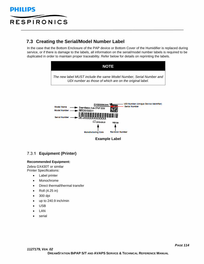
PAGE 114 1127179, VER. 02
DREAMSTATION BIPAP S/T AND AVAPS SERVICE & TECHNICAL REFERENCE MANUAL
7.3 Creating the Serial/Model Number Label In the case that the Bottom Enclosure of the PAP device or Bottom Cover of the Humidifier is replaced during service, or if there is damage to the labels, all information on the serial/model number labels is required to be duplicated in order to maintain proper traceability. Refer below for details on reprinting the labels.
NOTE
The new label MUST include the same Model Number, Serial Number and UDI number as those of which are on the original label.
Example Label
Equipment (Printer)
Recommended Equipment: Zebra GX430T or similar Printer Specifications:
• Label printer • Monochrome • Direct thermal/thermal transfer • Roll (4.25 in) • 300 dpi • up to 240.9 inch/min • USB • LAN • serial

PAGE 115 1127179, VER. 02
DREAMSTATION BIPAP S/T AND AVAPS SERVICE & TECHNICAL REFERENCE MANUAL
Software Recommended Software:
Loftware Software and Print Key (Fees Apply)
• For a full detailed list of Loftware supported printers and fees, please refer to http://www.loft-ware.com/support/tech_printers.cfm
• For software support, visit their website at www.loftware.com
Label Printing Options There are three different options available for reprinting the serial number label. One of these three options must be used. If option 3 cannot be duplicated to match the original label, options 1 and 2 may be used in its place.

PAGE 116 1127179, VER. 02
DREAMSTATION BIPAP S/T AND AVAPS SERVICE & TECHNICAL REFERENCE MANUAL
Chapter 8. Humidifier Repair and Replacement This Chapter illustrates the names and locations of the replaceable components in the DreamStation Humidi-fiers. Prior to executing these procedures, troubleshooting procedures must first be executed (refer to Chap-ter 6 for troubleshooting procedures.
IMPORTANT NOTE
The device must be tested after any repairs are made. Refer to Chapter 9 for details on testing the device.
WARNING
To prevent electrical shock, disconnect the Humidifier from the PAP device before attempting to make any repairs.
CAUTION
Components used in this device are subject to damage from static electricity. Repairs made to this device must be performed only in an anti-static, Electro-Static Discharge (ESD) protected environment.
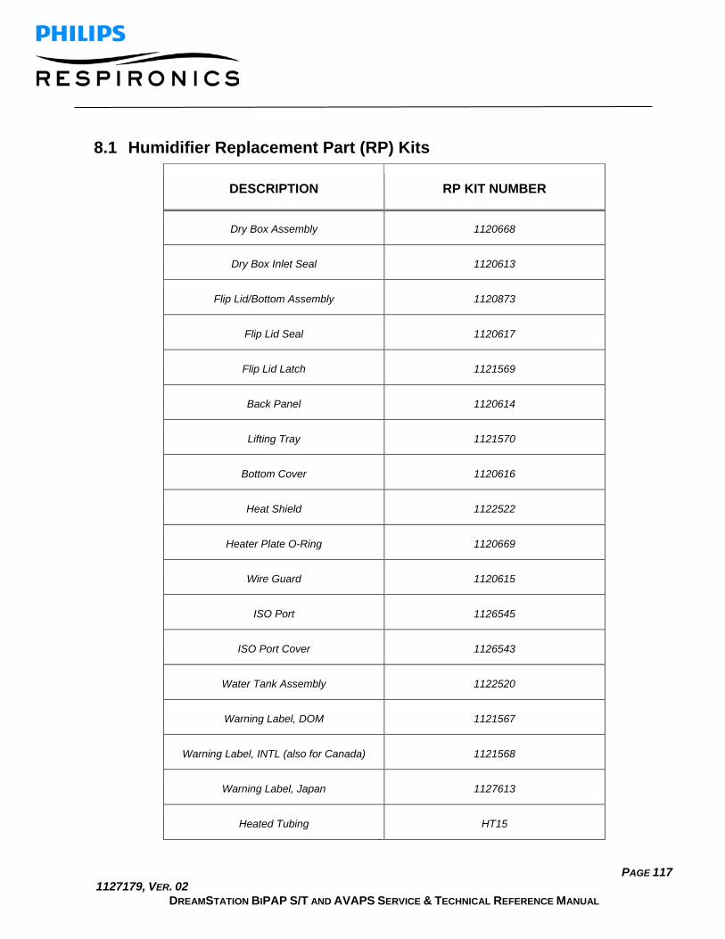
PAGE 117 1127179, VER. 02
DREAMSTATION BIPAP S/T AND AVAPS SERVICE & TECHNICAL REFERENCE MANUAL
8.1 Humidifier Replacement Part (RP) Kits
DESCRIPTION RP KIT NUMBER
Dry Box Assembly 1120668
Dry Box Inlet Seal 1120613
Flip Lid/Bottom Assembly 1120873
Flip Lid Seal 1120617
Flip Lid Latch 1121569
Back Panel 1120614
Lifting Tray 1121570
Bottom Cover 1120616
Heat Shield 1122522
Heater Plate O-Ring 1120669
Wire Guard 1120615
ISO Port 1126545
ISO Port Cover 1126543
Water Tank Assembly 1122520
Warning Label, DOM 1121567
Warning Label, INTL (also for Canada) 1121568
Warning Label, Japan 1127613
Heated Tubing HT15

PAGE 118 1127179, VER. 02
DREAMSTATION BIPAP S/T AND AVAPS SERVICE & TECHNICAL REFERENCE MANUAL
8.2 Replacement Instructions Prior to executing repair and replacement procedures, device troubleshooting must be performed. Refer to Chapter 6 for troubleshooting procedures.
Replacing the Water Tank Assembly
Kit Included in Kit Tools Required
Tank Assembly • Tank Assembly • None
To remove the Water Chamber Assembly:
1. Pull back on the latch located on the Bottom Assembly and lift up the Flip Lid. 2. Pull the Water Tank Assembly out of the Humidifier.
To Install the Water Tank Assembly:
1. Position the Water Tank back into the Humidifier as shown above. 2. Close the Flip Lid and verify it latches into place.
Pull back on latch
Tank Assembly

PAGE 119 1127179, VER. 02
DREAMSTATION BIPAP S/T AND AVAPS SERVICE & TECHNICAL REFERENCE MANUAL
Replacing the Flip Lid and Dry Box Inlet Seals
Kit Included in Kit Tools Required
Flip Lid Seal • Flip Lid Seal • None
Dry Box Seal • Dry Box Seal
To remove the Seals:
1. Remove the Water Tank as instructed in the previous section (not required for Flip Lid Seal replace-ment only).
2. Pull the Flip Lid Seal off of the Flip Lid and pull the Dry box Inlet Seal from the Dry Box Assembly.
GOOD BAD
Flip Lid Seal

PAGE 120 1127179, VER. 02
DREAMSTATION BIPAP S/T AND AVAPS SERVICE & TECHNICAL REFERENCE MANUAL
To Install the Seals:
1. Press the Seals into the place as shown above. 2. Press the Tank Top Seal onto the Patient Outlet Swivel Clip.
Note: The Seal only aligns one way. Be sure to press the Seal the whole way around to ensure it is seated properly.
Replacing the Dry Box Assembly
Kit Included in Kit Tools Required
Dry Box Assembly • Dry Box Assembly • None
To remove the Dry Box Assembly:
1. Remove the Water Tank and Dry Box Seal (refer to previous corresponding sections). 2. Pull back on the Dry Box Latch and pull the Dry Box out of the Bottom Assembly.
Dry Box Seal
Pull back on latch to remove
Dry Box Assembly

PAGE 121 1127179, VER. 02
DREAMSTATION BIPAP S/T AND AVAPS SERVICE & TECHNICAL REFERENCE MANUAL
To Install the Dry Box Assembly:
1. Position the Dry Box into the Bottom Assembly. 2. Snap the Dry Box into place and verify it is fully seated. 3. Assemble the remainder of the device as instructed in the previous sections.
Replacing the Wire Guard
Kit Included in Kit Tools Required
Wire Guard • Wire Guard • Flathead Screwdriver
To remove the Wire Guard:
1. Remove the Water Tank and Flip Lid Seal (refer to previous corresponding sections). 2. Push the bottom of the Wire Guard down and inward toward the Flip Lid while prying upward with a
small flathead screwdriver. 3. Pull the Wire Guard away from the Flip Lid.
Wire Guard Push at base of
Wire Guard and pry upward to remove

PAGE 122 1127179, VER. 02
DREAMSTATION BIPAP S/T AND AVAPS SERVICE & TECHNICAL REFERENCE MANUAL
To Install the Wire Guard:
1. Position the top of the Wire Guard into the Flip Lid groove and then position the bottom of the Wire Guard into place, but do not fully seat Wire Guard.
2. Verify wires are properly seated by wiping your finger across Wire Gard in location shown in the illus-
tration below. If Wire Guard is not flush with the Flip Lid surface, remove Wire Guard, re-seat wires, and reinstall Wire Guard. Repeat process if necessary.
3. Complete installation of the Wire Guard. 4. Assemble the remainder of the device as instructed in the previous sections.
Note: Ensure the wires are not pinched when installing the Wire Guard, and verify it is fully seated/secure (re-fer to illustrations below).

PAGE 123 1127179, VER. 02
DREAMSTATION BIPAP S/T AND AVAPS SERVICE & TECHNICAL REFERENCE MANUAL

PAGE 124 1127179, VER. 02
DREAMSTATION BIPAP S/T AND AVAPS SERVICE & TECHNICAL REFERENCE MANUAL
Replacing the Back Panel Assembly
Kit Included in Kit Tools Required
Back Panel Assembly • Back Panel Assembly • # 4 x 1/2” screws (qty 5)
• Torx Screwdriver (T10 is recommended)
To remove the Back Panel Assembly:
1. Remove the Water Chamber Assembly (refer to previous corresponding section). 2. Pull the Back Panel away from the Humidifier while lifting up on the top to release the Back Panel tab
from the latch area.
To install the Back Panel Assembly:
1. Align the Back Panel onto the Bottom Assembly. 2. Secure the Back Panel with the four # 4 x 1/2” screws (torque to 6 IN-LB). 3. Verify the Back Panel is fully seated/secure.
Torque screws to 6 IN-LB when installing Back Panel

PAGE 125 1127179, VER. 02
DREAMSTATION BIPAP S/T AND AVAPS SERVICE & TECHNICAL REFERENCE MANUAL
Replacing the Flip Lid Latch
Kit Included in Kit Tools Required
Flip Lid Latch • Flip Lid Latch • Torx Screwdriver (T10 is recommended)
To remove the Flip Lid Latch:
1. Remove the Back Panel Assembly and open the Flip Lid (refer to previous corresponding section). 2. Push up on the 2 Latch tabs and pull the Latch out of the Humidifier Assembly.
To install the Flip Lid Latch:
1. Align the Latch into the Bottom Assembly grooves. 2. Push up on the Latch tabs while pushing the Latch until it clicks into place. 3. Verify the Flip Lid latches into place.
Push tabs up and pull Latch out

PAGE 126 1127179, VER. 02
DREAMSTATION BIPAP S/T AND AVAPS SERVICE & TECHNICAL REFERENCE MANUAL
Replacing the Lifting Tray
Kit Included in Kit Tools Required
Lifting Tray • Lifting Tray • None
To remove the Lifting Tray:
1. Push out one side of the Lifting Tray out of the groove, and then repeat on the other side.

PAGE 127 1127179, VER. 02
DREAMSTATION BIPAP S/T AND AVAPS SERVICE & TECHNICAL REFERENCE MANUAL
2. Lift up the Lifting Tray and push one side inward out of the groove, and then repeat on the other side.
To install the Lifting Tray:
1. Place one end of the Lifting Tray back into the cut-out groove, and then repeat on other side. Note: The Tray will only fit one way into the groove. Refer to illustration below.
2. Once both ends of the Lifting Tray are placed into the cut-out holes, turn the Tray downward. 3. Pull back one of the other ends of the Lifting Tray and align into the groove (refer to illustration be-
low.). 4. Repeat on other side.

PAGE 128 1127179, VER. 02
DREAMSTATION BIPAP S/T AND AVAPS SERVICE & TECHNICAL REFERENCE MANUAL
Pull back Tray and align into groove
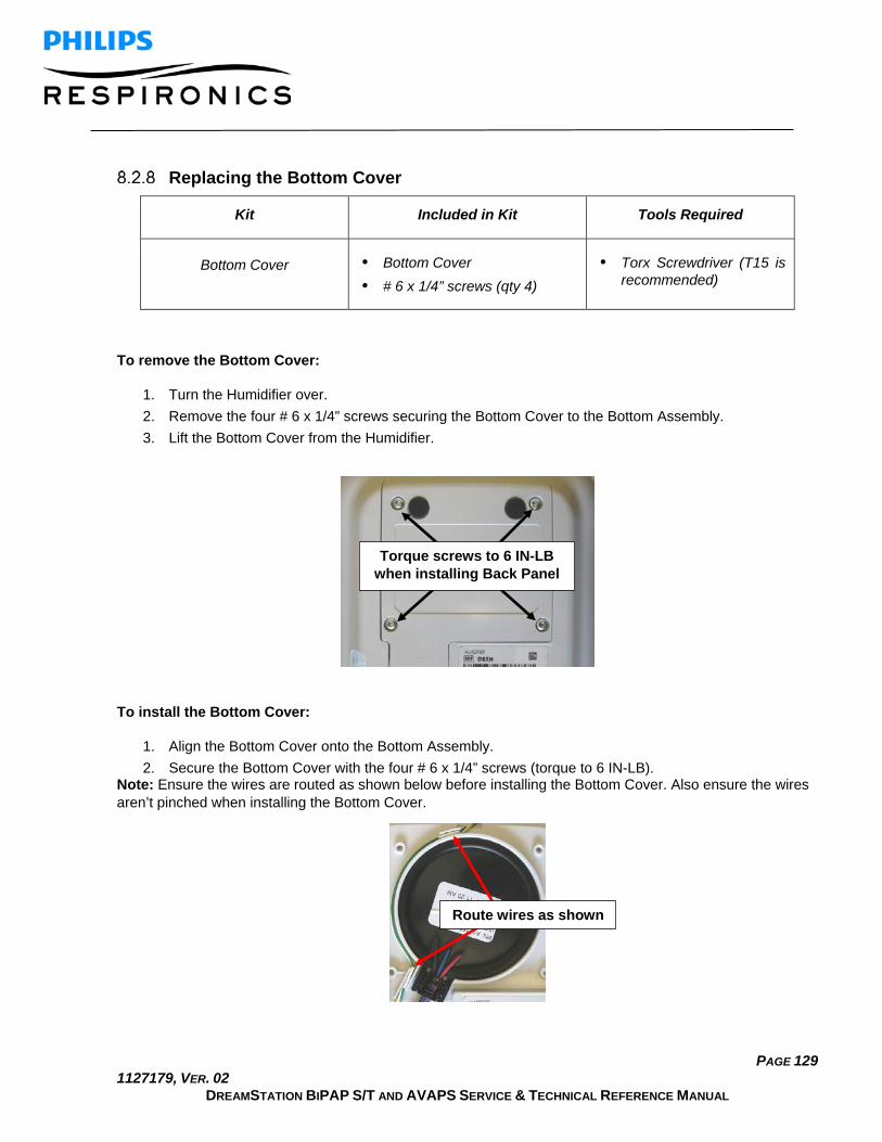
PAGE 129 1127179, VER. 02
DREAMSTATION BIPAP S/T AND AVAPS SERVICE & TECHNICAL REFERENCE MANUAL
Replacing the Bottom Cover
Kit Included in Kit Tools Required
Bottom Cover • Bottom Cover • # 6 x 1/4” screws (qty 4)
• Torx Screwdriver (T15 is recommended)
To remove the Bottom Cover:
1. Turn the Humidifier over. 2. Remove the four # 6 x 1/4” screws securing the Bottom Cover to the Bottom Assembly. 3. Lift the Bottom Cover from the Humidifier.
To install the Bottom Cover:
1. Align the Bottom Cover onto the Bottom Assembly. 2. Secure the Bottom Cover with the four # 6 x 1/4” screws (torque to 6 IN-LB).
Note: Ensure the wires are routed as shown below before installing the Bottom Cover. Also ensure the wires aren’t pinched when installing the Bottom Cover.
Torque screws to 6 IN-LB when installing Back Panel
Route wires as shown

PAGE 130 1127179, VER. 02
DREAMSTATION BIPAP S/T AND AVAPS SERVICE & TECHNICAL REFERENCE MANUAL
Replacing the Heat Shield
Included in Kit Included in Kit Tools Required
Heat Shield • Heat Shield • Torx Screwdriver (T15 is recommended)
To remove the Heat Shield:
1. Remove the Bottom Cover as instructed in the previous section. 2. Remove the Heat Shield from the Bottom Cover.
To install the Heat Shield:
1. Place the Heat Shield on the Bottom Cover as shown above. 2. Install the Bottom Cover as instructed in the previous section.
Route wires as shown

PAGE 131 1127179, VER. 02
DREAMSTATION BIPAP S/T AND AVAPS SERVICE & TECHNICAL REFERENCE MANUAL
Replacing the Heater Plate O-Ring
Included in Kit Included in Kit Tools Required
Heater Plate O-Ring • Heater Plate O-Ring • Torx Screwdriver (T15 is recommended)
To remove the Heater Plate O-Ring:
1. Remove the Bottom Cover as instructed in the previous section. 2. Lift up the Heater Plate. 3. Pull the O-Ring from the Bottom Assembly.
To install the Heater Plate O-Ring:
1. Place the O-Ring into the groove on the Bottom Assembly as shown in the above. 2. Place the Heater Plate back into position. 3. Install the Bottom Cover as instructed in the previous section.
Note: Ensure the Heater Plate is seated properly and the wires are routed as shown below before installing the Bottom Cover. Also ensure the wires aren’t pinched when installing the Bottom Cover.
Route wires as shown
Heater Plate O-Ring
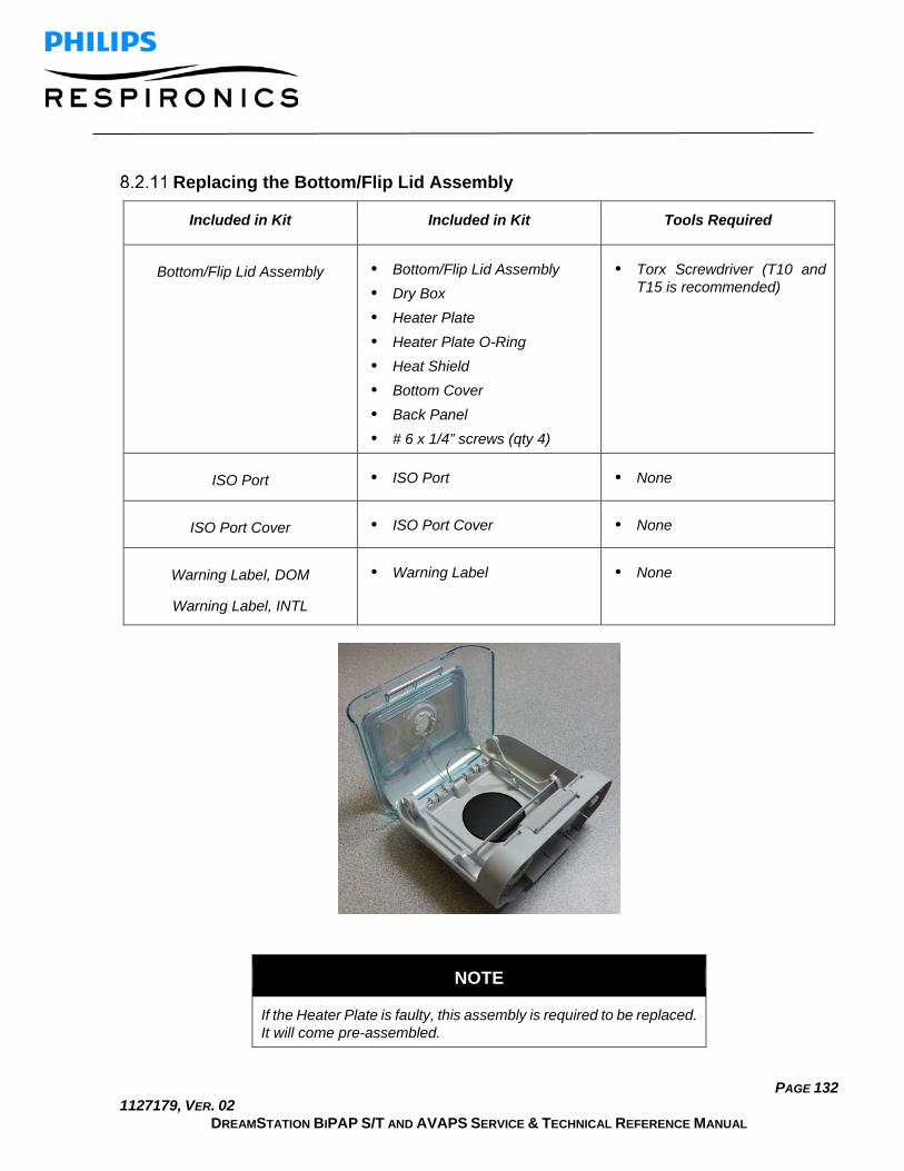
PAGE 132 1127179, VER. 02
DREAMSTATION BIPAP S/T AND AVAPS SERVICE & TECHNICAL REFERENCE MANUAL
Replacing the Bottom/Flip Lid Assembly
Included in Kit Included in Kit Tools Required
Bottom/Flip Lid Assembly • Bottom/Flip Lid Assembly • Dry Box • Heater Plate • Heater Plate O-Ring • Heat Shield • Bottom Cover • Back Panel • # 6 x 1/4” screws (qty 4)
• Torx Screwdriver (T10 and T15 is recommended)
ISO Port • ISO Port • None
ISO Port Cover • ISO Port Cover • None
Warning Label, DOM
Warning Label, INTL
• Warning Label • None
NOTE
If the Heater Plate is faulty, this assembly is required to be replaced. It will come pre-assembled.

PAGE 133 1127179, VER. 02
DREAMSTATION BIPAP S/T AND AVAPS SERVICE & TECHNICAL REFERENCE MANUAL
Removing/installing the Bottom/Flip Lid Assembly:
1. Remove the Tank Assembly, Flip Lid Seal, Dry Box Seal, and the Back Panel Assembly (refer to pre-vious corresponding sections).
2. Install Back Panel Assembly, Flip Lid Seal, Dry Box Seal and Tank Assembly onto the new Bot-tom/Flip Lid Assembly as instructed in the previous sections.
3. Place a new warning label and Serial/Model number label on the bottom of the Humidifier (refer to Section 7.3 for creating the Serial/Model number label.
4. Route the heated tube wire harness through the Flip Lid opening as shown below.
5. Install ISO Port Cover over heated tube wire harness.

PAGE 134 1127179, VER. 02
DREAMSTATION BIPAP S/T AND AVAPS SERVICE & TECHNICAL REFERENCE MANUAL
6. Install heated tube wire connector into ISO Port, and verify it is connected the whole way as shown below.
7. Install the ISO Port into the top opening of ISO Port Cover and snap into place.

PAGE 135 1127179, VER. 02
DREAMSTATION BIPAP S/T AND AVAPS SERVICE & TECHNICAL REFERENCE MANUAL
8. Verify the ISO Port is installed properly and flush with the ISO Port Cover.
9. Verify correct orientation of ISO Port assembly as shown below (port facing toward front of unit) and fully install ISO Port assembly into Flip Lid.

PAGE 136 1127179, VER. 02
DREAMSTATION BIPAP S/T AND AVAPS SERVICE & TECHNICAL REFERENCE MANUAL
10. Open the Flip Lid and ensure there are no pinched wires.
11. Route the wires flat as shown, and ensure they are in the middle within the grooves.
12. Install the Wire Guard.

PAGE 137 1127179, VER. 02
DREAMSTATION BIPAP S/T AND AVAPS SERVICE & TECHNICAL REFERENCE MANUAL
Chapter 9. Testing
Final testing of a device is a mandatory requirement after any repairs are made to the device, or if the device enclosure has been opened for any reason.
NOTE
Testing must occur in a lab equipment environment only.
9.1 Required Equipment Hardware:
• DreamStation Power Supply, 80W, (PN 1118499), Qty 1 ea. • DreamStation Serial Accessory Module (PN 1123881 or PN 1126240 (includes serial and micro-USB ca-
bles listed below)), Qty 1 ea. • Serial RS232 Cable DB9F-DB9M, 6 ft (PN 1037268), Qty 1 ea. • USB Cable, Type A to Micro B (PN 1104765), Qty. 1 ea. • Hose 22mm-18 in. (PN 1008198), Qty 1 ea. • 15mm Heated Tube (PN HT15), Qty 1 ea. • German Leak Device (ISO Port) (PN 1127131), Qty 1 ea. • Pollen Filter (PN 1122446), Qty 1 ea. • SD Card (PN 1063859 - 10 pk), Qty 1 ea. • Printer (network or local connection) • PC with the following minimum requirements:
• Windows 7 or Windows 10 32/64 Bit Operating System, Professional (Enterprise can be used for Philips network users only)
• 3.20 GHz Processor • 100 GB Free hard drive space • 8 GB RAM • 1 serial port • Minimum 4 USB port • Keyboard, mouse and 17 inch monitor • Supports 220 VAC +/- 10% and 50 Hz +/- 1Hz, or 120 VAC +/- 10% and 60 Hz +/- 1Hz power

PAGE 138 1127179, VER. 02
DREAMSTATION BIPAP S/T AND AVAPS SERVICE & TECHNICAL REFERENCE MANUAL
Software (download and install from my.respironics.com): • NI LabVIEW 2014 Support Package • DreamStation Family Drivers, Version 1.0 or higher • DreamStation Test Executive, Version 1.0 or higher (required if the DreamStation Field Service Applica-
tion is not already installed on your PC) • DreamStation BiPAP autoSV, S/T and AVAPS Field Service Application (FSA), Version 1.0.1 or higher
9.2 Testing Prerequisites Prior to testing any DreamStation device, the following must be ensured:
1. The device error log must be cleared. 2. The device real time clock must be accurate. 3. The DreamStation base unit and Humidifier must both be at room temperature. Refer to Section 9.3
for testing environmental specifications.
Refer to Chapter 6 on using the Service Center Tools software to clear the device error log and to reset the real time clock.
9.3 Testing Environment Specifications The DreamStation devices must be tested within the following temperature specifications:
41 º F to 95 º F (+5 º C to 35º C)
9.4 Software Download and Installation 1. Download the NI LabVIEW 2014 Support Package from my.respironics.com, and install the software
by accepting all license agreements and default installation locations. 2. Download the DreamStation Family Drivers from my.respironics.com, and unzip the files to your
PC. a. For Windows 7, run the installer and follow all prompts to install the drivers. b. For Windows 10, refer to Section 9.4.1 Windows 10 DreamStation Family Driver Installa-
tion. 3. Download the DreamStation Test Executive (if the DreamStation FSA is not already installed on
your PC), and install the Test Executive by accepting all license agreements and default installation locations.
4. Download the DreamStation BiPAP autoSV, S/T and AVAPS Field Service Application (FSA) from my.respironics.com, and install the software by accepting all license agreements and default in-stallation locations.
PAGE 139 1127179, VER. 02
DREAMSTATION BIPAP S/T AND AVAPS SERVICE & TECHNICAL REFERENCE MANUAL
Windows 10 DreamStation Family Drivers Installation Follow these steps to disable/enable signed driver enforcement on a Windows 10 system, so that the Dream-Station Family Drivers can be installed.
Disabling Driver Signature Enforcement in Windows 10:
1. Locate the Windows Command Prompt by typing in “CMD” in the Windows search engine (aka Cor-tana), then right click on the Command Prompt and select “Run as Administrator”.
2. Type in “ bcdedit -set loadoptions DISABLE_INTEGRITY_CHECKS” (do not include the quotations (“”)) then hit Enter on the keyboard.
3. To finalize the process, type “bcdedit -set TESTSIGNING ON” (do not include the quotations (“”)), then hit Enter on the keyboard.
4. Exit the Command prompt and reboot the PC. 5. Locate and install the DreamStation Family Drivers.
Notes: A Windows Security prompt should pop up. Select “Install this driver software anyway” when this prompt appears. In addition, the Command Prompt window will pop up. Do not close the Command Prompt window during the installation. Enabling Driver Signature Enforcement in Windows 10:
1. Locate the Windows Command Prompt by typing in “CMD” in the Windows search engine (aka Cor-tana), then right click on the Command Prompt and select “Run as Administrator”.
2. Type in “bcdedit -set loadoptions ENABLE_INTEGRITY_CHECKS” (do not include the quotations (“”), then hit Enter on the keyboard.
3. Type in “bcdedit -set TESTSIGNING OFF” (do not include the quotations (“”), then hit Enter on the keyboard.
4. Exit the Command prompt and reboot the PC.
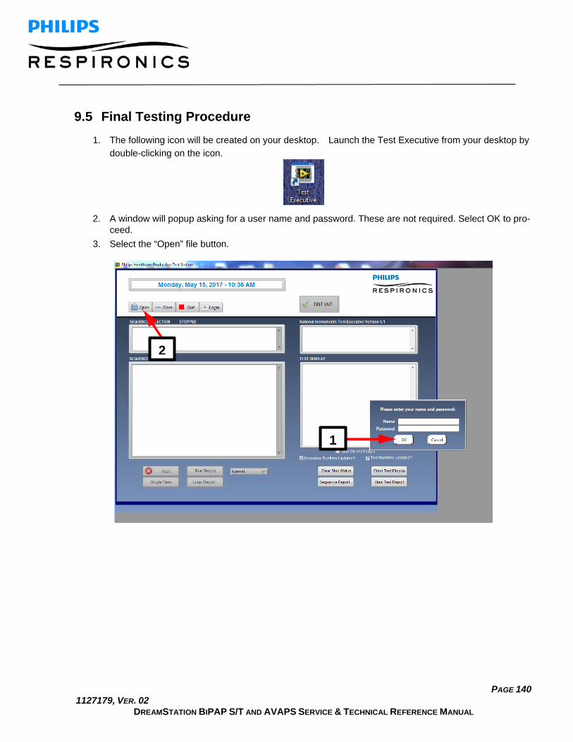
PAGE 140 1127179, VER. 02
DREAMSTATION BIPAP S/T AND AVAPS SERVICE & TECHNICAL REFERENCE MANUAL
9.5 Final Testing Procedure 1. The following icon will be created on your desktop. Launch the Test Executive from your desktop by
double-clicking on the icon.
2. A window will popup asking for a user name and password. These are not required. Select OK to pro-ceed.
3. Select the “Open” file button.
2
1
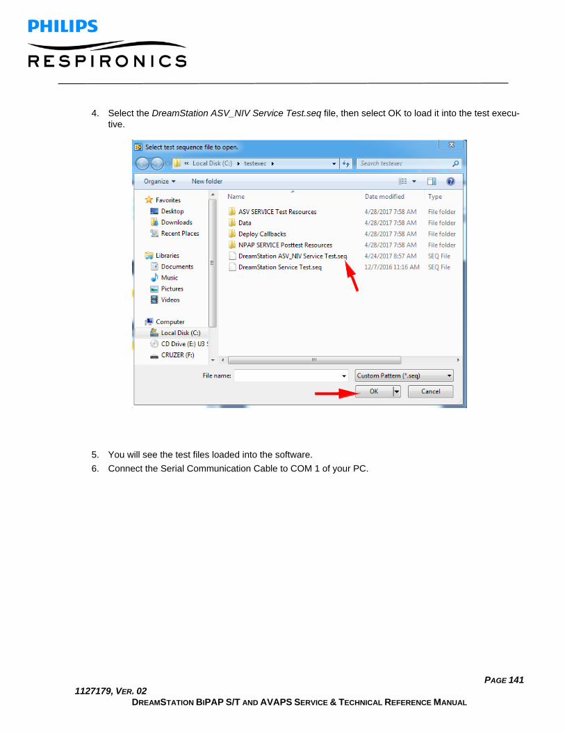
PAGE 141 1127179, VER. 02
DREAMSTATION BIPAP S/T AND AVAPS SERVICE & TECHNICAL REFERENCE MANUAL
4. Select the DreamStation ASV_NIV Service Test.seq file, then select OK to load it into the test execu-tive.
5. You will see the test files loaded into the software. 6. Connect the Serial Communication Cable to COM 1 of your PC.

PAGE 142 1127179, VER. 02
DREAMSTATION BIPAP S/T AND AVAPS SERVICE & TECHNICAL REFERENCE MANUAL
7. Select “Test UUT”.
8. Follow the prompts and enter in the device identification information (serial/model number, etc). 9. Follow the next prompt by connecting all hardware items listed and as shown below, and then select
OK. The Serial-USB Cable must be connected to COM 1. The Micro-USB Cable can be connected to any other USB COM port.

PAGE 143 1127179, VER. 02
DREAMSTATION BIPAP S/T AND AVAPS SERVICE & TECHNICAL REFERENCE MANUAL
10. Continue to follow all prompts. 11. Once the pressure and flow testing is complete, the following prompt will be displayed.
12. Connect the Humidifier and Heated Tube as shown below, then select OK.
13. Continue to follow all prompts until the test is complete. 14. If the test fails, evaluate for possible causes and make any necessary adjustments or repairs, and
then retest the device. 15. Print and keep a copy of the test report for your records.

PAGE 144 1127179, VER. 02
DREAMSTATION BIPAP S/T AND AVAPS SERVICE & TECHNICAL REFERENCE MANUAL