drdc toronto cr-2005-256 - defence research …cradpdf.drdc-rddc.gc.ca/pdfs/unc48/p525046.pdf ·...
TRANSCRIPT

DRDC Toronto CR-2005-256
DERIVATION OF OPTICAL AND LASER SIGHT OFFSETS
by:
Philip Gaughan
Humansystems© Incorporated 111 Farquhar St., 2nd floor
Guelph, ON N1H 3N4
Project Manager: David W. Tack (519) 836 5911
PWGSC Contract No. W7711-017747/001/TOR
Call-Up 7747-01 HSI® SIREQ Item #31
On behalf of
DEPARTMENT OF NATIONAL DEFENCE
as represented by Defence Research and Development Canada - Toronto
1133 Sheppard Avenue West Toronto, Ontario, Canada
M3M 3B9
DRDC Toronto Scientific Authority Maj Linda Bossi (416) 635-2197
August 2005
This document contains information that may not be passed or shared, even in confidence, with foreign military, research and development representatives or civilian contractors of any nationality
without the expressed prior permission of the Exploitation Manager of SIREQ TD.
The scientific or technical validity of this Contract Report is entirely the responsibility of the contractor and the contents do not necessarily have the approval or endorsement of Defence R&D
Canada
© Her Majesty the Queen as represented by the Minister of National Defence, 2005
© Sa Majesté la Reine, représentée par le ministre de la Défense nationale, 2005

Humansystems ® Derivation of Optical and Laser Sight Offsets Page i
Abstract
To prepare for the Soldier Information Requirements (SIREQ) project field experiment (Examination of the Effects of Night Vision Devices on Urban Off-Bore Target Detection and Engagement) the proposed sighting systems were trialled to determine a standardized laser boresighting and zeroing procedure. The resulting “master” offset targets provided a quick and efficient way to ensure standardization with respect to boresighting and zeroing the C7A1 Rifle for experiment participants. The offset sheets provide the appropriate targeting information for use with the AN/PEM-1 Laser Borelight System.
Representative “master” offset targets for each of the weapon/sight combinations are found in Annex A. The targets are representative in that they are scaled reproductions of the actual offset targets derived from the study.
Should any or all weapon sights/aiming aids be chosen and procured for the Canadian Forces, it is recommended that definitive offset targets be produced using bench test weapons and ammunition. The tests should also be conducted under pristine conditions (no wind, no shooter error, no qualitative determination of MPI, etc.).

Humansystems ® Derivation of Optical and Laser Sight Offsets Page ii
Résumé En préparation d’une expérience sur le terrain (Examen des effets de dispositifs de vision nocturne sur la détection et l’engagement de cibles hors de l’axe de visée en milieu urbain) dans le cadre du projet SIREQ (Soldier Information Requirements, ou besoins en information du soldat), les systèmes de visée proposés ont été mis à l’essai afin d’établir une procédure normalisée de simbleautage et de zérotage laser. Les cibles décalées « maîtresses » résultantes ont fourni aux participants de l’expérience un moyen rapide et efficace d’assurer la normalisation du simbleautage et du zérotage du fusil C7A1. Les feuilles de décalage présentent l’information de ciblage à utiliser avec le système de simbleautage laser AN/PEM-1.
Les cibles décalées « maîtresses » représentatives pour chacune des combinaisons arme-viseur sont présentées à l’annexe 1. Les cibles sont représentatives dans la mesure où ce sont des reproductions à l’échelle des cibles décalées réelles obtenues à partir de l’étude.
Pour tout choix et acquisition d’une partie ou de l’ensemble des viseurs d’arme et aides au pointage pour les Forces canadiennes, il est recommandé de produire des cibles décalées définitives en utilisant les munitions et les armes d’essai au banc. Les essais devraient en outre être menés dans ces conditions parfaites (absence de vent, d’erreurs du tireur, de détermination qualitative du PMI, etc.).

Humansystems ® Derivation of Optical and Laser Sight Offsets Page iii
Executive Summary To prepare for the Soldier Information Requirements (SIREQ) project field experiment (Examination of the Effects of Night Vision Devices on Urban Off-Bore Target Detection and Engagement) the proposed sighting systems were trialled to determine a standardized laser boresighting and zeroing procedure. This study was conducted at Winona Firing Range in Grimsby, Ontario, on 15 November 2001. The sighting systems evaluated included the following:
a. C79 Optical Sight; b. Iron Sight (Rear aperture add-on); c. Red Dot (Aimpoint) Scope; d. EOTECH Holographic Sight; e. CVL 001 Visible Laser; f. AN/PAQ-4C IR Laser; g. AN/PEQ-2A IR Flood and Laser.
The sequence of activities to generate the offset targets comprised of the following:
• Laser boresight • Shooting • Confirmation of Zero point • Recording of borelight offsets • Confirmation of borelight zero
The resulting “master” offset targets provided a quick and efficient way to ensure standardization with respect to boresighting and zeroing the C7A1 Rifle for experiment participants. The offset sheets provide the appropriate targeting information for use with the AN/PEM-1 Laser Borelight System.
Representative “master” offset targets for each of the weapon/sight combinations are found in Annex A. The targets are representative in that they are scaled reproductions of the actual offset targets derived from the study.
Should any or all weapon sights/aiming aids be chosen and procured for the Canadian Forces, it is recommended that definitive offset targets be produced using bench test weapons and ammunition. The tests should also be conducted under pristine conditions (no wind, no shooter error, no qualitative determination of MPI, etc.).

Humansystems ® Derivation of Optical and Laser Sight Offsets Page iv
Sommaire
En préparation d’une expérience sur le terrain (Examen des effets de dispositifs de vision nocturne sur la détection et l’engagement de cibles hors de l’axe de visée en milieu urbain dans le cadre du projet SIREQ (Soldier Information Requirements, ou besoins en information du soldat), les systèmes de visée proposés ont été mis à l’essai afin d’établir une procédure normalisée de simbleautage et de zérotage laser. Cette étude a été menée au Winona Firing Range, à Grimsby (Ontario), le 15 novrembre 2001. Les systèmes de visée évalués comprenaient les suivants :
a. Viseur optique C79; b. Dispositif de visée métallique (à oeilleton d’appoint); c. Viseur à marqueur à tache rouge (point de visée); d. Viseur holographique EOTECH; e. Laser visible CVL 001; f. Laser AN/PAQ-4C IR; g. Dispositif IR et laser AN/PEQ-2A.
La séquence d’activités pour la production des cibles décalées comprenait ce qui suit :
• Simbleautage laser • Tir • Confirmation du point zéro • Enregistrement des décalages de simbleau • Confirmation du zéro de simbleau
Les cibles décalées « maîtresses » résultantes ont fourni aux participants de l’expérience un moyen rapide et efficace d’assurer la normalisation du simbleautage et du zérotage du fusil C7A1. Les feuilles de décalage présentent l’information de ciblage à utiliser avec le système de simbleautage laser AN/PEM-1.
Les cibles décalées « maîtresses » représentatives pour chacune des combinaisons arme-viseur sont présentées à l’annexe 1. Les cibles sont représentatives dans la mesure où ce sont des reproductions à l’échelle des cibles décalées réelles obtenues à partir de l’étude.
Pour tout choix et acquisition d’une partie ou de l’ensemble des viseurs d’arme et aides au pointage pour les Forces canadiennes, il est recommandé de produire des cibles décalées définitives en utilisant les munitions et les armes d’essai au banc. Les essais devraient en outre être menés dans ces conditions parfaites (absence de vent, d’erreurs du tireur, de détermination qualitative du PMI, etc.).

Humansystems ® Derivation of Optical and Laser Sight Offsets Page v
Table of Contents
ABSTRACT ......................................................................................................................................................I
RÉSUMÉ......................................................................................................................................................... II
EXECUTIVE SUMMARY ...........................................................................................................................III
SOMMAIRE ..................................................................................................................................................IV
TABLE OF CONTENTS ............................................................................................................................... V
LIST OF FIGURES.......................................................................................................................................VI
1. BACKGROUND .................................................................................................................................... 1
2. AIM ......................................................................................................................................................... 3
3. METHOD ............................................................................................................................................... 3 3.1. SUBJECTS ........................................................................................................................................ 3 3.2. STIMULI AND APPARATUS ............................................................................................................... 3
3.2.1 C79 Optical Sight ...................................................................................................................... 4 3.2.2 Iron Sight (Rear aperture Add-on) ............................................................................................ 4 3.2.3 Red Dot (Aimpoint) Scope ......................................................................................................... 4 3.2.4 EOTech Holographic Sight........................................................................................................ 5 3.2.5 CVL 001 Visible Laser (Insight Technology Incorporated)....................................................... 5 3.2.6 AN/PAQ-4C IR Laser (Insight Technology Incorporated) ........................................................ 6 3.2.7 AN/PEQ-2A IR Target Pointer/Illuminator/Aiming Laser (Insight Technology Incorporated) 6 3.2.8 AN/PEM-1 Laser Borelight System (Insight Technology Incorporated) ................................... 7
3.3. TEST ENVIRONMENT ....................................................................................................................... 8 3.4. GENERAL PROCEDURE..................................................................................................................... 8
3.4.1 Boresighting............................................................................................................................... 8 3.4.2 Zeroing....................................................................................................................................... 9 3.4.3 Laser Offset Recording .............................................................................................................. 9 3.4.4 Confirmation of Borelight Zero ................................................................................................. 9
4. RESULTS ............................................................................................................................................. 10
5. DISCUSSION ....................................................................................................................................... 11
6. REFERENCES..................................................................................................................................... 12
ANNEX A: BORE SIGHTING TEMPLATES.........................................................................................A-1

Humansystems ® Derivation of Optical and Laser Sight Offsets Page vi
List of Figures FIGURE 1: C79 OPTICAL SIGHT (ELCAN)............................................................................................................ 4 FIGURE 2: AIMPOINT (RED DOT) COMPM2 SIGHT......................................................................................... 5 FIGURE 3: EOTECH HOLOGRAPHIC WEAPON SIGHT .......................................................................................... 5 FIGURE 4: CVL CARBINE VISIBLE LASER .......................................................................................................... 6 FIGURE 5: AN/PAQ-4C IR LASER (MOUNTED TO C7A1 RIFLE) ........................................................................ 6 FIGURE 6: INSIGHT TECHNOLOGY INC. AN/PAQ-4C INFRARED AIMING LIGHT ................................................ 7 FIGURE 7: LASER BORELIGHT SYSTEM (WITH MANDRELS) ................................................................................ 7 FIGURE 8: LASER BORELIGHT SYSTEM (MOUNTED ON C7A1 RIFLE).................................................................. 8

Humansystems ® Derivation of Optical and Laser Sight Offsets Page 1
1. Background There are a number of new sighting systems that support close combat rifle engagements, including aim points and laser sights. These devices are marketed as significantly improving day and night shooting performance. Isolated studies and field research have identified a number of advantages and disadvantages with rifle sighting systems. Whilst not exhaustive, the effectiveness of rifle sighting systems can be examined in terms of precision accuracy, speed of target acquisition and engagement, attention narrowing, ease of adjustment, and durability. While open or iron sights are very durable and hold their aim, they are difficult to aim quickly to deliver precision accuracy. Conversely, optical sights are more fragile, even more difficult to use quickly, and cause attention narrowing. However, they do offer precision accuracy. Laser sights are affected by environmental factors and are limited by eye-safe laser safety considerations. The latest optical technology in rifle aiming systems is the reflex sight or red-dot aiming sight. These sights are advertised as improving day and night rapid target engagement performance. A number of military forces and police forces are now equipped with light un-cooled thermal weapon sights. While the benefits of these systems are well known to police emergency response teams and military special force teams, controlled field trial evidence is not available. In order to assess the performance and benefits of these novel sights the Soldier Information Requirements -Technology Demonstration (SIREQ-TD) Project has conducted a series of scientific investigations. One of these studies (Angel & Hawes, 2004) involved live firing on a combat range. The sighting systems evaluated included the following:
a. C79 Optical Sight;
b. Iron Sight (Rear aperture add-on);
c. Red Dot (Aimpoint) Scope;
d. EOTECH Holographic Sight;
e. CVL 001 Visible Laser;
f. AN/PAQ-4C IR Laser; and
g. AN/PEQ-2A IR Flood and Laser.
Sights and rifles must be accurately aligned with the user’s Point of Aim (POA) in order to properly assess the effects of the sight on subject performance. According to CFP 317-018 (1987) paragraphs 421.3-421.4 “The act of zeroing is to superimpose the true position of the Mean Point of Impact (MPI) on the Correct Zero Position (CZP) so that with the appropriate sight setting and wind allowance the group will form centrally at all other ranges.… It is essential that each soldier zero his or her own rifle.” For this study, the rifle

Humansystems ® Derivation of Optical and Laser Sight Offsets Page 2
referred to in the final sentence quoted is taken to refer to the entire rifle-sight system. In layman’s terms zeroing is the adjustment of sights achieved by live firing and the actions of the shooter to bring the rifle sights into a position so that when accurately fired by the soldier for whom it has been adjusted, the weapon fires rounds to the centre of the target. Proper zeroing requires the shooter to fire a large number of shots, not less than 20, fired at the same aiming mark under the same conditions. As well, the firer must be capable of consistently achieving an average of a 200 mm group with five rounds at 100 metres (CFP 317-018).
Traditionally zeroing the C7 rifle is undertaken at 100m, but it can be zeroed at 25m if required. The zeroing procedure may also begin with preliminary sight adjustment or boresighting so that the first rounds fired during the zeroing procedure will hit the target. A number of optical and laser systems are now available to allow operators to boresight their weapon in a field location, within seconds, without going to a 25 or 100m range. While there may be differences with each shooter in zeroing their sight and weapon, successful boresighting and zeroing (for some sights) can be accomplished with the use of predetermined aiming point offsets at 10 or 25m.
A number of zeroing offsets have been developed by the US forces for the use of the AN/PAQ-4C and AN/PEQ-2A Laser Aiming Devices (LADs) with their M16, M4A1, M249, M2, and M60 weapon systems. The LADs can be attached to these weapons using a number of different brackets or rail grabbers and the zeroing offsets change depending on the location where the LAD is attached to the weapon, e.g. left side rail, right side rail, top rail, hand guard bracket etc. The SIREQ-TD Project is using the Knight Technology Rail Interface System (RIS) or hand guards to attach LADS to the C7 rifle and while these rail systems are similar to those found on the M4A1 concerns were raised as to the possible effect of zeroing offsets. As well zeroing offsets for the Aimpoint and EOTech optical sights were not available for the C7 rifle. Given the significant time demands to live zero the C7 and the variety of different sighting systems it was decided by the SIREQ-TD Project team to develop standardized laser boresighting and zeroing procedures for the novel sights under investigation. The resulting procedures would be used to achieve significant economies in preparation and setup timings for trials in Ft Benning.
Participants were required to perform standard C7 Rifle grouping and application serials in order to zero each weapon/sight combination. The data collected for off-set boresighting formed the baseline for laser boresighting and zeroing tasks with each sight. The resulting “master” offsets targets provided a quick and efficient way to ensure standardization with respect to boresighting and zeroing the C7A1 Rifle for experiment participants.

Humansystems ® Derivation of Optical and Laser Sight Offsets Page 3
2. Aim The aim of this field study was to develop boresighting procedures and laser bore light aim point offsets for a variety of optical and laser sights.
3. Method This study was conducted at Winona Firing Range in Grimsby, Ontario, on 15 November 2001. The study involved the derivation of borelight laser zeroing offsets.
3.1. Subjects Two volunteers (one major and one captain) from the 11th Field Regiment, Royal Canadian Artillery, Canadian Forces Primary Reserve were recruited to participate in this study. The subjects were selected based upon their shooting ability (they both achieved the highest possible scores on their Personal Weapons Test (PWT) for the past three consecutive years.)
3.2. Stimuli and Apparatus The targets for live fire zeroing portion of this study were Figure 11 paper targets superimposed on a 1.3 m high witness screen with a suitable white aiming mark.
Humansystems ® Derivation of Optical and Laser Sight Offsets Page 4
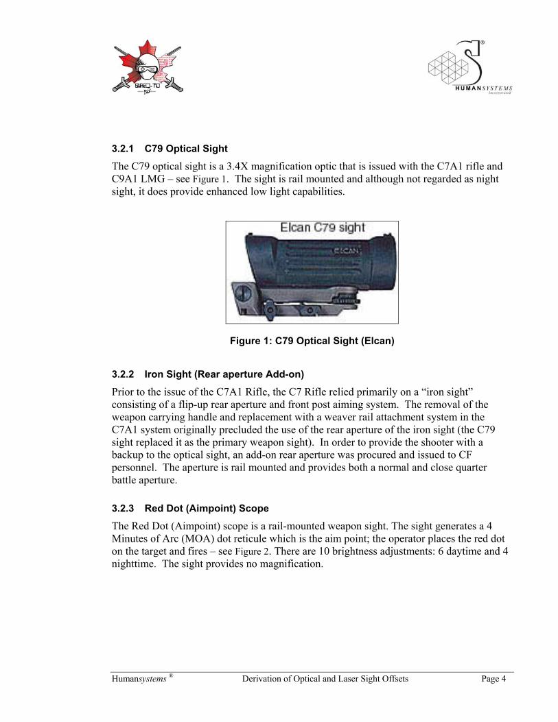
3.2.1 C79 Optical Sight
The C79 optical sight is a 3.4X magnification optic that is issued with the C7A1 rifle and C9A1 LMG – see Figure 1. The sight is rail mounted and although not regarded as night sight, it does provide enhanced low light capabilities.
Figure 1: C79 Optical Sight (Elcan)
3.2.2 Iron Sight (Rear aperture Add-on)
Prior to the issue of the C7A1 Rifle, the C7 Rifle relied primarily on a “iron sight” consisting of a flip-up rear aperture and front post aiming system. The removal of the weapon carrying handle and replacement with a weaver rail attachment system in the C7A1 system originally precluded the use of the rear aperture of the iron sight (the C79 sight replaced it as the primary weapon sight). In order to provide the shooter with a backup to the optical sight, an add-on rear aperture was procured and issued to CF personnel. The aperture is rail mounted and provides both a normal and close quarter battle aperture.
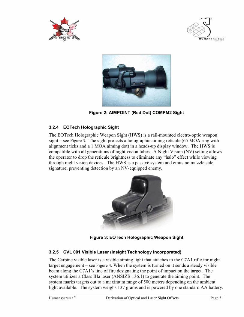
3.2.3 Red Dot (Aimpoint) Scope
The Red Dot (Aimpoint) scope is a rail-mounted weapon sight. The sight generates a 4 Minutes of Arc (MOA) dot reticule which is the aim point; the operator places the red dot on the target and fires – see Figure 2. There are 10 brightness adjustments: 6 daytime and 4 nighttime. The sight provides no magnification.
Humansystems ® Derivation of Optical and Laser Sight Offsets Page 5
Figure 2: AIMPOINT (Red Dot) COMPM2 Sight
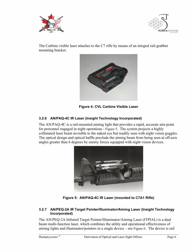
3.2.4 EOTech Holographic Sight
The EOTech Holographic Weapon Sight (HWS) is a rail-mounted electro-optic weapon sight – see Figure 3. The sight projects a holographic aiming reticule (65 MOA ring with alignment ticks and a 1 MOA aiming dot) in a heads-up display window. The HWS is compatible with all generations of night vision tubes. A Night Vision (NV) setting allows the operator to drop the reticule brightness to eliminate any “halo” effect while viewing through night vision devices. The HWS is a passive system and emits no muzzle side signature, preventing detection by an NV-equipped enemy.
Figure 3: EOTech Holographic Weapon Sight
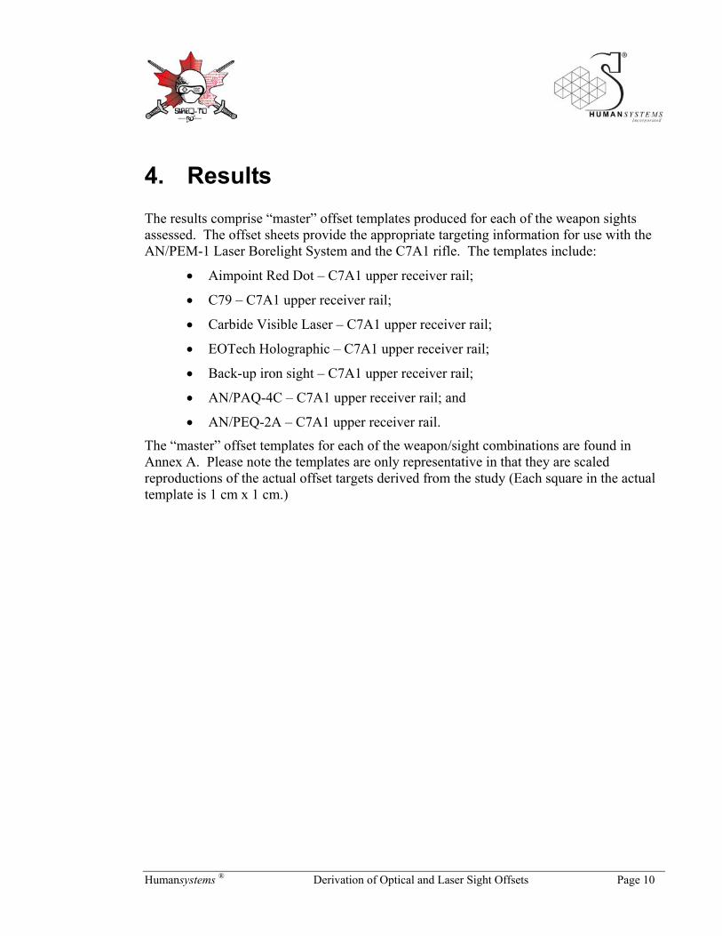
3.2.5 CVL 001 Visible Laser (Insight Technology Incorporated)
The Carbine visible laser is a visible aiming light that attaches to the C7A1 rifle for night target engagement – see Figure 4. When the system is turned on it sends a steady visible beam along the C7A1’s line of fire designating the point of impact on the target. The system utilizes a Class IIIa laser (ANSIZB 136.1) to generate the aiming point. The system marks targets out to a maximum range of 500 meters depending on the ambient light available. The system weighs 137 grams and is powered by one standard AA battery.
Humansystems ® Derivation of Optical and Laser Sight Offsets Page 6
The Carbine visible laser attaches to the C7 rifle by means of an integral rail-grabber mounting bracket.
Figure 4: CVL Carbine Visible Laser
3.2.6 AN/PAQ-4C IR Laser (Insight Technology Incorporated)
The AN/PAQ-4C is a rail-mounted aiming light that provides a rapid, accurate aim point for personnel engaged in night operations - Figure 5. The system projects a highly collimated laser beam invisible to the naked eye but readily seen with night vision goggles. The optical design and optical baffle preclude the aiming beam from being seen at off-axis angles greater than 6 degrees by enemy forces equipped with night vision devices.
Figure 5: AN/PAQ-4C IR Laser (mounted to C7A1 Rifle)
3.2.7 AN/PEQ-2A IR Target Pointer/Illuminator/Aiming Laser (Insight Technology Incorporated)
The AN/PEQ-2A Infrared Target Pointer/Illuminator/Aiming Laser (ITPIAL) is a dual beam multi-function laser, which combines the utility and operational effectiveness of aiming lights and illuminator/pointers in a single device – see Figure 6. The device is rail

Humansystems ® Derivation of Optical and Laser Sight Offsets Page 7
mounted and provides adjustment settings for elevation and windage for both the aiming and illuminator beams. The illumination beam is able to focus from a pinpoint spot to a wide-angle flood. The aim spot of the aiming beam can be centered in the illumination area.
Figure 6: Insight Technology Inc. AN/PAQ-4C Infrared Aiming Light
3.2.8 AN/PEM-1 Laser Borelight System (Insight Technology Incorporated)
The Laser Borelight System (LBS) is a Class IIIa laser that emits a highly collimated beam of visible light for precise zeroing of an aiming light or weapon sight to the weapon - see Figure 7 and Figure 8. The LBS includes mandrels which are attached inline to the visible laser component of the borelight. The assembly is inserted into the muzzle end of the weapon to accomplish weapon boresighting. The LBS can be used with any weapon-sight combination using naked eyes, direct view optics, or night vision device.
Figure 7: Laser Borelight System (with Mandrels)

Humansystems ® Derivation of Optical and Laser Sight Offsets Page 8
Figure 8: Laser Borelight System (mounted on C7A1 Rifle)
The LBS includes offset targets for use with a variety of weapon sights and laser aiming units. The offsets provided are intended for use with the US M16A2 Rifle as well as the M249 Light Machine Gun as well as the new M240B Machine Gun.
3.3. Test Environment The testing was conducted during clear and dry weather conditions at the Winona Firing Range in Grimsby, Ontario, on 15 November 2001. The mean temperature (09:00 – 16:00hrs) was 25.7ºC with an average wind speed (09:00 – 16:00hr) of 12 Km/h from the southwest. The Winona Range is a known distance range with firing points at 100, 200 and 300m and the range is oriented to the northeast (resulting in little cross winds on the range).
3.4. General procedure The sequence of activities followed to generate the boresighting offset templates comprised the following:
• Laser boresighting
• Grouping and zeroing
• Confirmation of Zero point
• Recording of borelight offsets
• Confirmation of borelight zero
These procedures are described in further detail below.
3.4.1 Boresighting
The laser boresighting procedure began by selecting the correct mandrel for the caliber of the weapon and attaching it to the borelight. The weapon was then stabilized (in a

Humansystems ® Derivation of Optical and Laser Sight Offsets Page 9
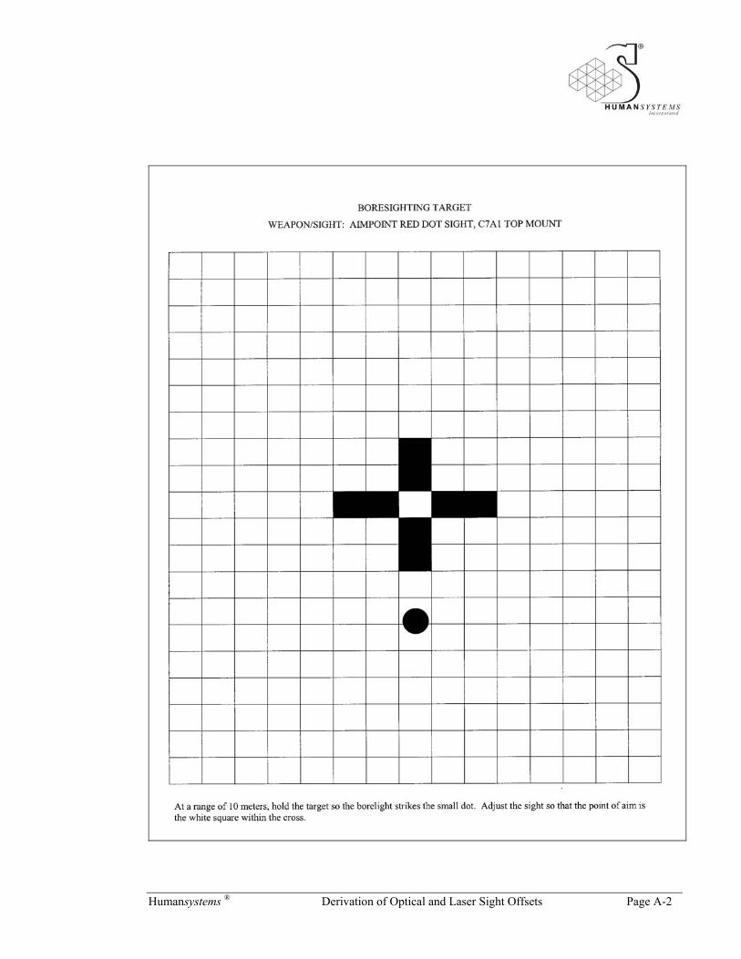
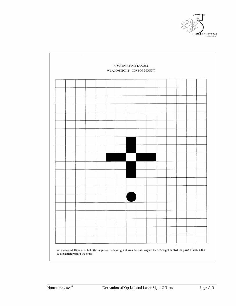
weapons box or by using sandbags, etc) and the mandrel was inserted into the muzzle of the weapon. The borelight was rotated with the unit turned on to ensure that the laser beam was centered with the bore of the weapon. Appropriate templates (see Annex A) provided by the Laser Borelight System were placed 10 meters from the muzzle of the weapon using the measuring cord included with the Laser Borelight. The elevation and azimuth of the sight or LAD were adjusted to match the required aim point offsets. The offsets used at this stage of the study were those provided with the Laser Borelight System, and while they were generated for the M16A2 rifle, they provided a starting point for boresighting the various sights.
3.4.2 Zeroing
After boresighting the sights the participants moved to the firing range and zeroed their weapons. The participants followed the zeroing procedures detailed in CFP 317-018 (1987). With the various sights or aiming lights affixed to the weapon, the shooter fired a series of 5 round groupings from the 100 meter firing point at a Figure 11 target (standard CF range target). After each grouping serial the shooters inspected their results and measured the size of their group. As well adjustments were made to the weapon sight in order to ensure that the MPI of the grouping and point of aim were coincidental. Shooters who achieved a 15 cm grouping at their point of aim moved back to the 200 meter firing point to confirm their groupings.
3.4.3 Laser Offset Recording
Following a successful shoot, the firers moved back to the laser borelight station and offsets were determined. This procedure involved securing the rifle into a rest. The borelight was rotated with the unit turned on to ensure that the laser beam was centered. The shooter aimed for the template cross-hair and once satisfied the location of the borelight was recorded. The borelight location was then marked and the offset in elevation and azimuth for the sight to the borelight aim point was recorded.
The offsets developed for each sight for both shooters were recorded. The offset values were compared and no notable differences were observed for the sights. A master off-set was then prepared for each sight.
3.4.4 Confirmation of Borelight Zero
Once the borelight zeroing offsets were developed they were confirmed by the two shooters using different sights and weapons. The two shooters used the offsets to “dry zero” their weapon and then proceeded to perform a live fire confirmatory zero.
Humansystems ® Derivation of Optical and Laser Sight Offsets Page 10
4. Results The results comprise “master” offset templates produced for each of the weapon sights assessed. The offset sheets provide the appropriate targeting information for use with the AN/PEM-1 Laser Borelight System and the C7A1 rifle. The templates include:
• Aimpoint Red Dot – C7A1 upper receiver rail;
• C79 – C7A1 upper receiver rail;
• Carbide Visible Laser – C7A1 upper receiver rail;
• EOTech Holographic – C7A1 upper receiver rail;
• Back-up iron sight – C7A1 upper receiver rail;
• AN/PAQ-4C – C7A1 upper receiver rail; and
• AN/PEQ-2A – C7A1 upper receiver rail.
The “master” offset templates for each of the weapon/sight combinations are found in Annex A. Please note the templates are only representative in that they are scaled reproductions of the actual offset targets derived from the study (Each square in the actual template is 1 cm x 1 cm.)
Humansystems ® Derivation of Optical and Laser Sight Offsets Page 11
5. Discussion AN/PEM-1 Laser Borelight System zeroing offsets were developed for a variety of sights and the C7A1 rifle. While the results of this trial provide offset targets for the C7A1 rifle and the sighting systems tested, they provide a quick reference only. In order to determine the definitive offsets for these systems, a more rigorous and detailed study should be conducted. As mentioned in the Background section, the study was performed to establish a quick zeroing and boresighting procedure that would reduce the significant delays introduced by the requirement to zero several different weapon/sight combinations prior to SIREQ-TD testing. The weapon/sight combinations still required a confirmation zero to be performed in order to ensure that engagement data, with respect to accuracy, was valid.
Should any or all weapon sights/aiming aids be chosen and procured for the Canadian Forces, it is recommended that definitive offset targets be produced using bench test weapons and ammunition. The tests should also be conducted under pristine conditions (no wind, no shooter error, no qualitative determination of MPI).

Humansystems ® Derivation of Optical and Laser Sight Offsets Page 12
6. References A. Angel, H.A., &Hawes, H.J. (2004). Examination of the Effect of Night Vision
Devices on C7A1 Target Engagement Accuracy. (DRDC T Report CR 2004-173). Toronto, ON: Defence Research and Development Canada – Toronto
B. Chief of the Defence Staff. (1987). WEAPONS VOLUME 18: THE RIFLE 5.56 Mm C7 AND THE CARBINE 5.56 mm C8. CFP B-GL-317-018/PT-001. Queens Printers. Ottawa, ON
Humansystems ® Derivation of Optical and Laser Sight Offsets Page A-1
ANNEX A: Bore Sighting Templates
AN/PEM-1 Laser Borelight Offsets For Use With C7A1 Upper Receiver Rail
Humansystems ® Derivation of Optical and Laser Sight Offsets Page A-2
Humansystems ® Derivation of Optical and Laser Sight Offsets Page A-3

Humansystems ® Derivation of Optical and Laser Sight Offsets Page A-4

Humansystems ® Derivation of Optical and Laser Sight Offsets Page A-5

Humansystems ® Derivation of Optical and Laser Sight Offsets Page A-6
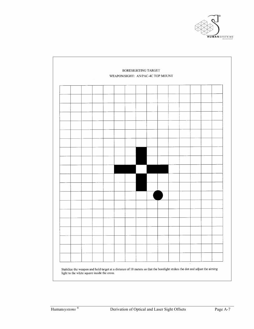
Humansystems ® Derivation of Optical and Laser Sight Offsets Page A-7

Humansystems ® Derivation of Optical and Laser Sight Offsets Page A-8
UNCLASSIFIED
DOCUMENT CONTROL DATA(Security classification of the title, body of abstract and indexing annotation must be entered when the overall document is classified)
1. ORIGINATOR (The name and address of the organization preparing the document, Organizationsfor whom the document was prepared, e.g. Centre sponsoring a contractor's document, or taskingagency, are entered in section 8.)
Publishing: DRDCToronto
Performing: Humansystems® Incorporated, 111 Farquhar St., 2ndfloor, Guelph, ON N1H 3N4
Monitoring:
Contracting: DRDCToronto
2. SECURITY CLASSIFICATION(Overall security classification of the documentincluding special warning terms if applicable.)
UNCLASSIFIED
3. TITLE (The complete document title as indicated on the title page. Its classification is indicated by the appropriate abbreviation (S, C, R, or U) in parenthesis atthe end of the title)
Derivation of Optical and Laser Sight Offsets (U)Calcul des Décalages de Viseurs Optiques et Laser
4. AUTHORS (First name, middle initial and last name. If military, show rank, e.g. Maj. John E. Doe.)
Philip Gaughan
5. DATE OF PUBLICATION(Month and year of publication of document.)
August 2005
6a NO. OF PAGES(Total containing information, includingAnnexes, Appendices, etc.)
35
6b. NO. OF REFS(Total cited in document.)
2
7. DESCRIPTIVE NOTES (The category of the document, e.g. technical report, technical note or memorandum. If appropriate, enter the type of document,e.g. interim, progress, summary, annual or final. Give the inclusive dates when a specific reporting period is covered.)
Contract Report
8. SPONSORING ACTIVITY (The names of the department project office or laboratory sponsoring the research and development − include address.)
Sponsoring: DLR 5, NDHQ OTTAWA,ON K1A 0K2
Tasking:
9a. PROJECT OR GRANT NO. (If appropriate, the applicableresearch and development project or grant under which the document waswritten. Please specify whether project or grant.)
12QG01
9b. CONTRACT NO. (If appropriate, the applicable number under whichthe document was written.)
W7711−017747/001/TOR
10a. ORIGINATOR'S DOCUMENT NUMBER (The officialdocument number by which the document is identified by the originatingactivity. This number must be unique to this document)
DRDC Toronto CR 2005−256
10b. OTHER DOCUMENT NO(s). (Any other numbers under whichmay be assigned this document either by the originator or by thesponsor.)
SIREQ #31
11. DOCUMENT AVAILABILIY (Any limitations on the dissemination of the document, other than those imposed by security classification.)
Defence departments in approved countries − Document has initial limited distributionthrough Exploitation Manager − TTCP and NATO countries and agencies − Unlimitedafter initial limited distribution
12. DOCUMENT ANNOUNCEMENT (Any limitation to the bibliographic announcement of this document. This will normally correspond to the DocumentAvailability (11), However, when further distribution (beyond the audience specified in (11) is possible, a wider announcement audience may be selected.))
Other − Document to have initial Limited announcement
UNCLASSIFIED

UNCLASSIFIED
DOCUMENT CONTROL DATA(Security classification of the title, body of abstract and indexing annotation must be entered when the overall document is classified)
13. ABSTRACT (A brief and factual summary of the document. It may also appear elsewhere in the body of the document itself. It is highly desirable that the abstract
of classified documents be unclassified. Each paragraph of the abstract shall begin with an indication of the security classification of the information in the paragraph(unless the document itself is unclassified) represented as (S), (C), (R), or (U). It is not necessary to include here abstracts in both official languages unless the text isbilingual.)
(U) To prepare for the Soldier Information Requirements (SIREQ) project field experiment(Examination of the Effects of Night Vision Devices on Urban Off−Bore Target Detectionand Engagement) the proposed sighting systems were trialled to determine astandardized laser boresighting and zeroing procedure. The resulting “master” offsettargets provided a quick and efficient way to ensure standardization with respect toboresighting and zeroing the C7A1 Rifle for experiment participants. The offset sheetsprovide the appropriate targeting information for use with the AN/PEM−1 Laser BorelightSystem.Representative “master” offset targets for each of the weapon/sight combinations arefound in Appendix 1. The targets are representative in that they are scaled reproductionsof the actual offset targets derived from the study.Should any or all weapon sights/aiming aids be chosen and procured for the CanadianForces, it is recommended that definitive offset targets be produced using bench testweapons and ammunition. The tests should also be conducted under pristine conditions(no wind, no shooter error, no qualitative determination of MPI, etc.).
14. KEYWORDS, DESCRIPTORS or IDENTIFIERS (Technically meaningful terms or short phrases that characterize a document and could be helpful in
cataloguing the document. They should be selected so that no security classification is required. Identifiers, such as equipment model designation, trade name,military project code name, geographic location may also be included. If possible keywords should be selected from a published thesaurus, e.g. Thesaurus ofEngineering and Scientific Terms (TEST) and that thesaurus identified. If it is not possible to select indexing terms which are Unclassified, the classification of eachshould be indicated as with the title.)
(U) Soldier Information Requirements Technology Demonstration Project; SIREQ TD; OpticalSight; Laser Sight; Sight Offsets; boresighting; zeroing; aim; weapon sight
UNCLASSIFIED