drawing systems & procedures - caliber design
TRANSCRIPT

www.caliberdesign.co.nz HO
W T
O G
UID
E
Drawing Systems
& Procedures
Eight key ideas for
working smarter
In order to consistently create professional engineering
drawings, it is important to have a well thought out
system that works for you.
Can you answer these questions?
Do you have procedures in place to ensure
that every drawing produced is to a defined
standard?
Do you have templates set up to save you
time, money, and rework?
Does your revision system eliminate potential
confusion?
Are you employing advanced techniques
such as drawing development macros to
make your life easier?
If you are serious about producing professional
drawings efficiently and to a high standard then
you should be able to confidently answer these
questions.
Read on for some more tips on how to start
improving your drawing systems today!
Think about your 3D CAD drawing system
The key is to develop a system that minimises upfront and
ongoing time, so the next time a project needs drawings,
everyone on your team knows exactly what is expected of
them.

Before you draw, you need a plan!
The most important part of a quality drawing system is laying out
your procedures clearly.
Start a procedures document with a step-by-step guide on how to
create a drawing. Templates, naming structure, drawing standards etc
should all be listed to avoid future confusion. This is an example of a
drawing procedure index:
Drawings should be laid out similarly so you can present professional
drawing packs. This can be achieved with templates (discussed later)
and sufficient detail in your procedures document.
Everyone should be trained or made aware of the relevant drawing
standard for your company and/or client. That way you can be sure
that every engineer is creating drawings with the same symbols,
dimensions, hole callouts, etc.
1. PROCEDURES
Where do I start? How do I do it?

Templates greatly increase the speed at which drawings can be created. Plus,
a good template ensures your drawings will contain the necessary information
every time.
Poor templates require you to enter text directly, update multiple sheets for
changes and type in notes—ultimately costing you time and money.
A drawing template with a border and title block should be set up for part,
weldment, and assembly drawings. A good template will contain some of the
following:
NOTES FOR THE RELEVANT DRAWING: This way you know the
correct information will be captured for each case. For example, the
weldment drawing should mention the likes of specific welding tolerances
and standards, whilst the part drawing may have surface finish notes.
Drawings should mention material type, grade, and supplier. If it’s a plastic
part, include the allowable visual imperfections and flash, etc.
LIBRARY NOTES: Create templates for commonly used notes and
symbols and store them in your CAD library. Then they can easily be
dragged into drawings, saving time and ensuring repeatability.
AUTOMATIC PROPERTIES: These will save you time without having
to update the title block for every sheet if there is a change! A good
template will automatically update information such as dates and names.
Furthermore the details for the drawing should be entered in the custom
properties area, so any update will automatically be extrapolated to all
relevant sheets.
LINK YOUR PROPERTIES: If, for example, your drawing template has
an entry for cut length, make sure that the actual value is linked to the
model. The last thing you want is someone updating the model but the
drawing still shows the old cut length!
2. TEMPLATES
There’s no need to reinvent the wheel!
A good template will never have you entering data directly
into the title block or BOM!

Have you ever opened a part and wondered where the drawing is, or what
assembly it came from?
Use a workable structure! Naming your files sensibly will mean it’s
easy to group together parts, assemblies, and their respective drawings.
Create a system in your procedures and stick to it! If all of your engineers
are working to the same structure, confusion can be avoided.
The structure shown below is clearly numbered and ordered so its obvious
where to look. Create something that makes sense for you workflow.
Note that any ordered part numbering system always has exceptions and
inconsistencies. We recommend just having a number which means
nothing, but is unique. There are lots of ways to sort by part, weldment,
assembly etc. These days it is not
so necessary to sort your files
like this due to CAD tracking
technology.
Experiment and work
out a system that’s
best for you!
3. FILE STRUCTURE
Setup a system for everyone to follow

Having a good checking system is paramount to catching
problems before they leave the office and supplying the
customer with quality drawings.
First of all, print and check your own drawing. Self checking is an
essential and measurable activity that can drive down rework.
If possible, have someone else check your drawings. A fresh set of
eyes will often notice errors that you have missed. Ideally your ‘checker’
will be more experienced than you. Dedicated checkers are valuable in
the context of maintaining drawing standards.
Have a procedure for signing off drawings so someone is responsible
for making sure they have been checked and marked up as required.
That way you know it was done!
4. CHECKING
Catch mistakes before it’s too late
Revisions mean you can easily and efficiently keep track of what’s
changing and why. Without a solid revision system, changes may be lost
and items could be manufactured to old drawings.
In the initial stages, drawings should be labelled Draft00, Draft01 etc.
The purpose of draft revisions is that many changes are expected in the
initial stages of development.
Once the drawing is deemed suitable for release, the revision should be
changed to Released to “re-set” the changes.
Revision tables should show what has changed between releases.
This is used by the manufacturer to identify what he needs to adjust for
the next item.
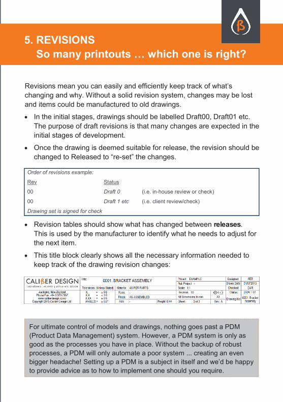
This title block clearly shows all the necessary information needed to
keep track of the drawing revision changes:
5. REVISIONS
So many printouts … which one is right?
For ultimate control of models and drawings, nothing goes past a PDM
(Product Data Management) system. However, a PDM system is only as
good as the processes you have in place. Without the backup of robust
processes, a PDM will only automate a poor system ... creating an even
bigger headache! Setting up a PDM is a subject in itself and we’d be happy
to provide advice as to how to implement one should you require.
Order of revisions example:
Rev Status
00 Draft 0 (i.e. in-house review or check)
00 Draft 1 etc (i.e. client review/check)
Drawing set is signed for check

Keep a record! Hard copies with changes scribbled on them should be
filed in a project folder. This way they can be looked at later to see why
a change was made. Include asbuilts in your records.
All revision bumps should be saved out as PDFs. It only takes a
second, and means you can refer to old drawings easily when needed.
Another tip is to ensure you have ’Previous Version’ enabled within
your system setup.
Redundant saves in an ordered environment is not confusing and limits
the need to bother your IT department to restore backups when
required.
Backup your backups! If your hard drive ever has a problem you will
still need access to the latest files. With the right network setup
this can be done automatically.
Don’t send your CAD files directly to just everyone! Even if you
have signed NDAs, sending a PDF might be better.
Use a PDF writer that has the option to add security to your files.
This can stop images or text from being copied, the document
from being modified, or even the document from being printed.
If you need to you can even add a password to open files or time
limit them.
6. BACKUPS
Anything that can go wrong, will go wrong!
7. IP PROTECTION
Engage advanced technologies

Macros can be employed to do boring repetitive
tasks in an instant.
Here are some examples of helpful macros that you could
implement:
Replace sheet format macro—replaces the sheet format for
your set of drawings.
A custom properties macro can be used to automatically fill in
basic properties and create boxes for users to enter data.
Revision macros can save out your drawing set from Draft
to Released or vice-versa.
Save as PDF macros can save out a whole folder of
drawings as PDFs and/or print the drawing to hard copy. Use
this when you think your drawing set is ready for a release
pack.
Make DXFs macro—automate output of DXF files of your flat
patterns for an updated drawing pack.
8. MACROS
Why waste your time on repetitive tasks

So, what should a professional drawing system
include?
1. PROCEDURES: Setup a ‘procedures document’ so that drawing files
are setup in a consistent way. Keep your procedures up to date,
encourage you team to add to them, and insist that everyone in your
team to use them!
2. TEMPLATES: Invest some time in setting up a solid drawing
template and you’ll save yourself time and energy on every job, and
reduce the chance of mistakes sneaking in!
3. FILE STRUCTURE: Create a file naming structure that makes
sense for your workplace and your workflow. Document it and stick to it.
4. CHECKING: A well thought out review procedure ensures that
every drawing gets checked thoroughly every time. Print and check
your drawings thoroughly. Have someone else check your drawings.
5. REVISIONS: Develop a clear and efficient system for keeping track
of what’s changing and why it changed. Without one, changes may be
lost and items manufactured to old drawings!
6. BACKUPS: Files get lost, computer systems break down. Keep
hard copy records of your work, save revisions, and backup your
backups.
7. IP PROTECTION: Your intellectual property is a valuable asset.
Don’t distribute your CAD files unnecessarily—PDFs often suffice. Use
the security settings within your PDF writer to your advantage.
8. MACROS: Use your software’s capabilities to the max and you’ll save
time and money. Macros can be setup to do boring repetitive tasks in
an instant.
Quick Summary

Caliber Design is a engineering, analysis, and mechanical
design consultancy.
Our team of expert engineers has multi-disciplinary experience
across a diverse range of industries and products. This broad
base means you get the benefit of engineers who ….
can innovate and engineer products successfully
have hands on experience over multiple industry types
are experienced working in multiple environments over a
wide range of product groups
Engineering design projects can be complex and provide
significant risk to business. At Caliber we specialise in
mitigating design risk. Our experienced team embed analysis
and engineering rigor into every project. Caliber will help you
design and manufacture better quality products, achieve a
better time to market, and net a greater return on investment.
About Us
Call the Caliber team now for a no obligation discussion
about your next project. We can very quickly provide
you with an estimate for a product requirements
specification that will set you up for a successful
project.
Visit us at www.caliberdesign.co.nz for contact
information.

Our robust drawing systems help us produce quality drawings every time with minimal hassle.
This How To Guide includes some key ideas to help you setup an effective drawing system.
Ultimately your company will reach a new level of professionalism for your customers, whilst saving both time and money. It’s a win-win for everyone!
© Caliber Design Ltd. All rights reserved.
Caliber Design | 97 Cook Street, Auckland 1010
E [email protected] | P +64 9 379 7357
www.caliberdesign.co.nz