drawing machines workshop - university of utah school of computing
TRANSCRIPT
Drawing Machines Workshop SIGGRAPH 2013
Overview: The workshop is about computing in an arts context. This hands-‐on introduction to physical computing and embedded programming will have participants make computer-‐controlled machines that make drawings. Using Arduino C-‐based software, attendees will build circuits and modify code to control sensors and servos. Art materials are used to turn the circuits into mesmerizing contraptions that draw.
Instructors: Erik Brunvand, School of Computing, University of Utah ([email protected]) Ginger Alford, Trinity Valley School, Ft. Worth, TX ([email protected]) Paul Stout, Dept. of Art and Art History, Univ. of Utah ([email protected])
Motivation: Arduino and microcontrollers like it have invigorated students, hobbyists, and makers of all types to add electronics and computer control to their hand-‐made contraptions. The integration of electronics and electro-‐mechanical components with computer control is known more generally as physical computing.
A concise definition from Wikipedia is: Physical computing, in the broadest sense, means building interactive physical systems by the use of software and hardware that can sense and respond to the analog world.
For artists, this provides tools that enable interaction with people and the environment. For engineers, this is an exciting and novel creative context for technology. For educators, this is a powerful way to introduce programming and physical computing concepts to students from high school to undergraduate and to students who might not normally be intrigued by a computer engineering course. The workshop will include a brief introduction to Drawing Machines, establishing a creative and artistic context in which the technical content will be explored in the workshop. Workshop participants will build (in teams) a simple drawing machine using foam core, nuts/bolts, and masking tape. The machine will be controlled using potentiometers and servos connected to an Arduino microcontroller. Topics that are covered by this activity include basics of microcontroller programming and electronic components, including how to use a breadboard, how to read a circuit diagram and how to interact with the physical world using programmatic control of a variety of input and output components.
Contents of Kit (one per team) (please return after the workshop) • Arduino microcontroller (either Duemilanove or Uno) • Solderless breadboard • Wires for connecting components • Two standard 180° servos • Two potentiometers (blue plastic) • Assorted LEDs • 220Ω resistors (red red brown stripes) • Two CDS light sensors (squiggly lines on flat top) • 10kΩ resistors (brown black orange stripes) • USB cable • Masking tape
Shared supplies
• Foam core board • Box cutters for cutting foam core (please cut on masonite cuttings boards) • Pens, pencils, markers, etc. • Extra servos • Extra wires • Extra LEDs • Extra resistors • Extra potentiometers • Extra light sensors • Assorted screws, washers, nuts, etc. • Drawing papers rolls (cut off 2ft sections for making drawings) • Wood blocks for drawing machine supports • Extension wires for connecting servos to breadboard
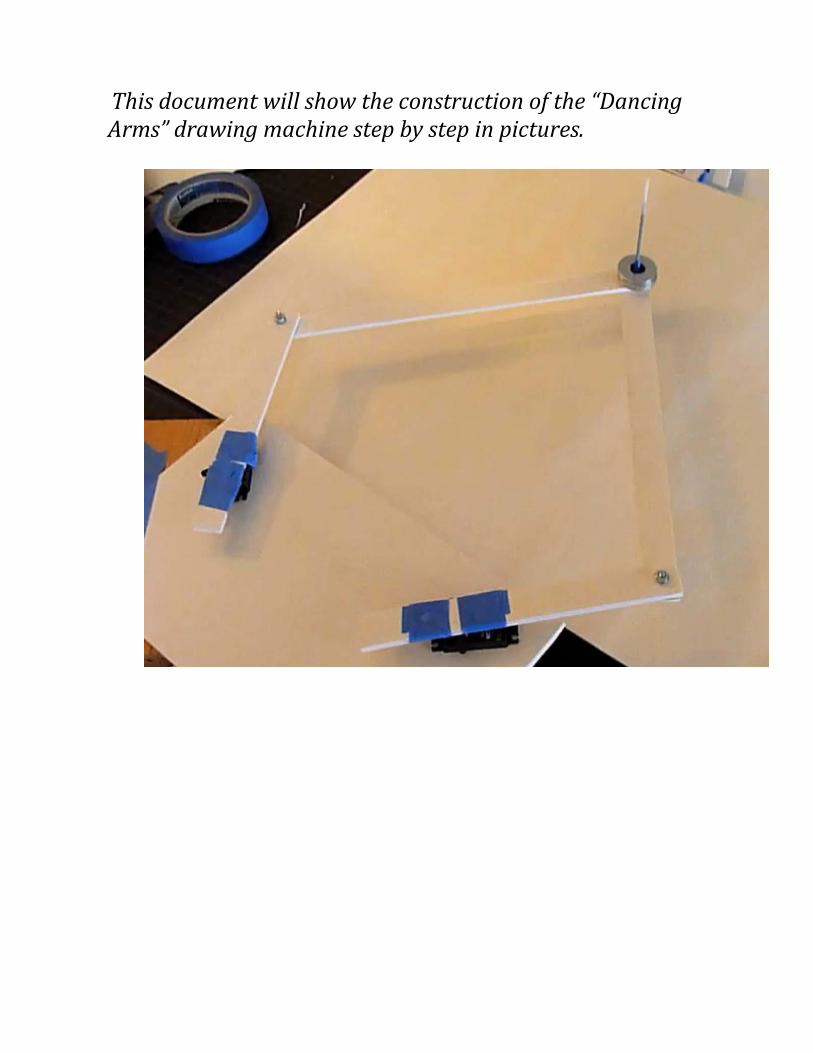
This document will show the construction of the “Dancing Arms” drawing machine step by step in pictures.
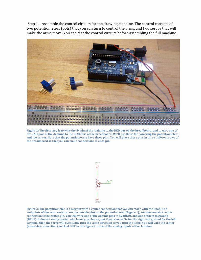
Step 1 – Assemble the control circuits for the drawing machine. The control consists of two potentiometers (pots) that you can turn to control the arms, and two servos that will make the arms move. You can test the control circuits before assembling the full machine.
Figure 1: The first step is to wire the 5v pin of the Arduino to the RED bus on the breadboard, and to wire one of the GND pins of the Arduino to the BLUE bus of the breadboard. We’ll use these for powering the potentiometers and the servos. Note that the potentiometers have three pins. You will place those pins in three different rows of the breadboard so that you can make connections to each pin.
Figure 2: The potentiometer is a resistor with a center connection that you can move with the knob. The endpoints of the main resistor are the outside pins on the potentiometer (Figure 1), and the movable center connection is the center pin. You will wire one of the outside pins to 5v (RED), and one of them to ground (BLUE). It doesn’t really matter which one you choose, but if you choose 5v for the right and ground for the left terminal then the servo will eventually turn the same direction as you turn the knob. You will wire the center (movable) connection (marked OUT in this figure) to one of the analog inputs of the Arduino.
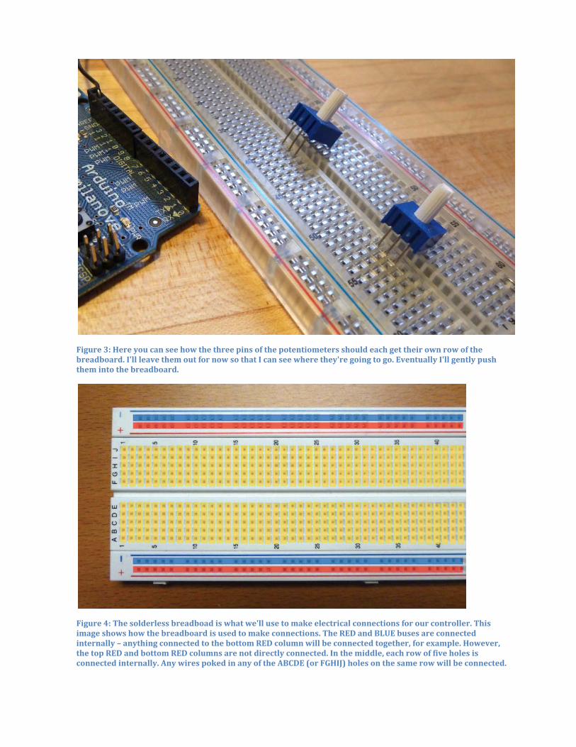
Figure 3: Here you can see how the three pins of the potentiometers should each get their own row of the breadboard. I'll leave them out for now so that I can see where they're going to go. Eventually I'll gently push them into the breadboard.
Figure 4: The solderless breadboad is what we'll use to make electrical connections for our controller. This image shows how the breadboard is used to make connections. The RED and BLUE buses are connected internally – anything connected to the bottom RED column will be connected together, for example. However, the top RED and bottom RED columns are not directly connected. In the middle, each row of five holes is connected internally. Any wires poked in any of the ABCDE (or FGHIJ) holes on the same row will be connected.
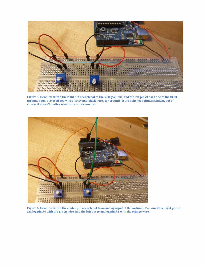
Figure 5: Here I've wired the right pin of each pot to the RED (5v) bus, and the left pin of each one to the BLUE (ground) bus. I've used red wires for 5v and black wires for ground just to help keep things straight, but of course it doesn’t matter what color wires you use.
Figure 6: Here I've wired the center pin of each pot to an analog input of the Arduino. I've wired the right pot to analog pin A0 with the green wire, and the left pot to analog pin A1 with the orange wire.
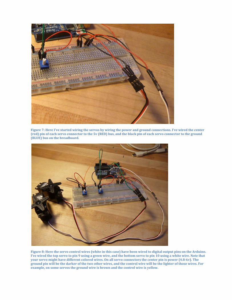
Figure 7: Here I've started wiring the servos by wiring the power and ground connections. I’ve wired the center (red) pin of each servo connector to the 5v (RED) bus, and the black pin of each servo connector to the ground (BLUE) bus on the breadboard.
Figure 8: Here the servo control wires (white in this case) have been wired to digital output pins on the Arduino. I’ve wired the top servo to pin 9 using a green wire, and the bottom servo to pin 10 using a white wire. Note that your servo might have different colored wires. On all servo connectors the center pin is power (4.8-6v). The ground pin will be the darker of the two other wires, and the control wire will be the lighter of those wires. For example, on some servos the ground wire is brown and the control wire is yellow.
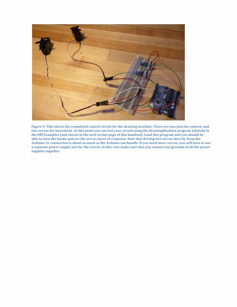
Figure 9: This shows the completed control circuit for the drawing machine. There are two pots for control, and two servos for movement. At this point you can test your circuit using the DrawingMachine program (sketch) in the DM Examples (and shown in the next-to-last page of this handout). Load this program and you should be able to turn the knobs and see the servos move in response. Note that driving two servos directly from the Arduino 5v connection is about as much as the Arduino can handle. If you need more servos, you will have to use a separate power supply just for the servos. In this case make sure that you connect toe grounds of all the power supplies together.
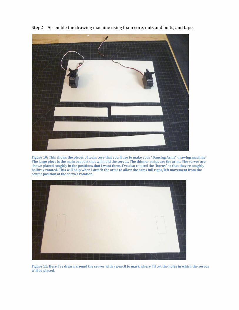
Step2 – Assemble the drawing machine using foam core, nuts and bolts, and tape.
Figure 10: This shows the pieces of foam core that you'll use to make your "Dancing Arms" drawing machine. The large piece is the main support that will hold the servos. The thinner strips are the arms. The servos are shown placed roughly in the positions that I want them. I’ve also rotated the “horns” so that they’re roughly halfway rotated. This will help when I attach the arms to allow the arms full right/left movement from the center position of the servo’s rotation.
Figure 11: Here I've drawn around the servos with a pencil to mark where I'll cut the holes in which the servos will be placed.
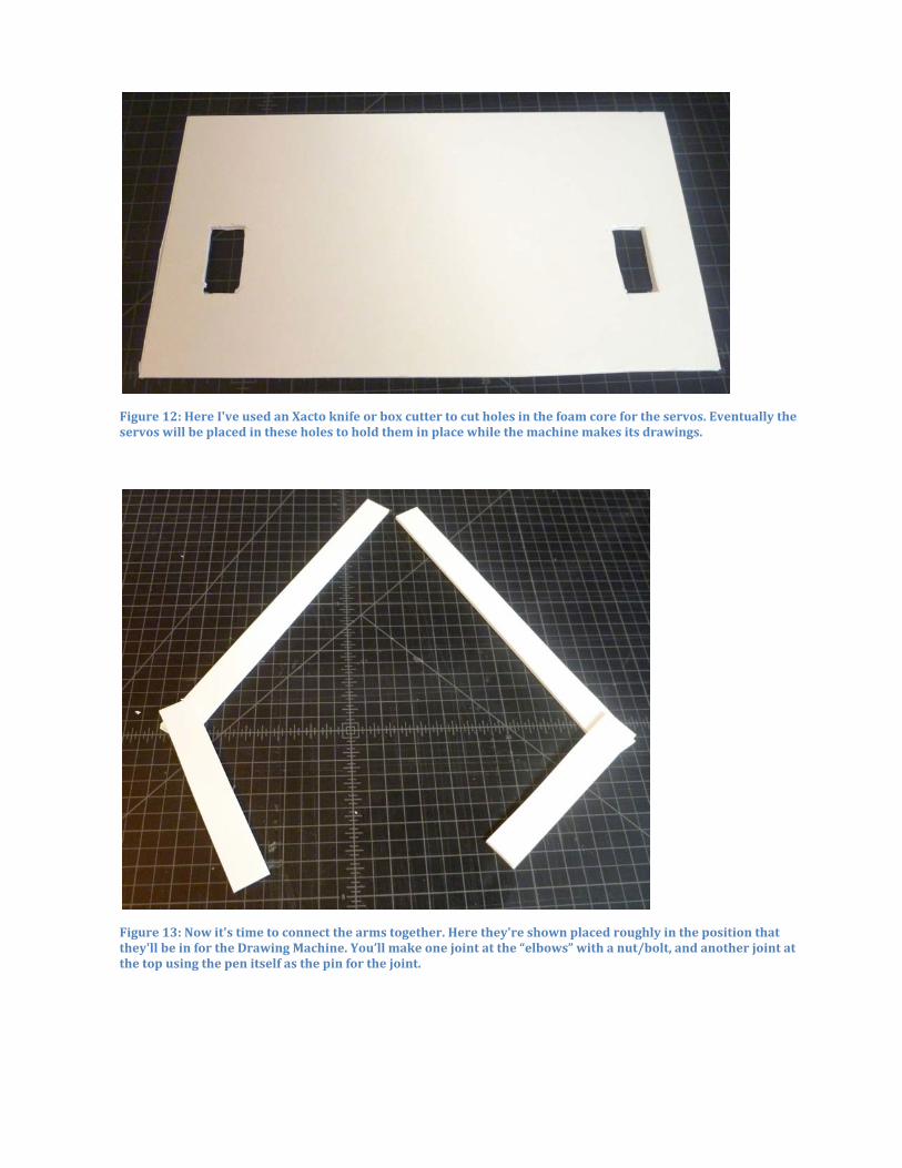
Figure 12: Here I've used an Xacto knife or box cutter to cut holes in the foam core for the servos. Eventually the servos will be placed in these holes to hold them in place while the machine makes its drawings.
Figure 13: Now it's time to connect the arms together. Here they're shown placed roughly in the position that they'll be in for the Drawing Machine. You’ll make one joint at the “elbows” with a nut/bolt, and another joint at the top using the pen itself as the pin for the joint.
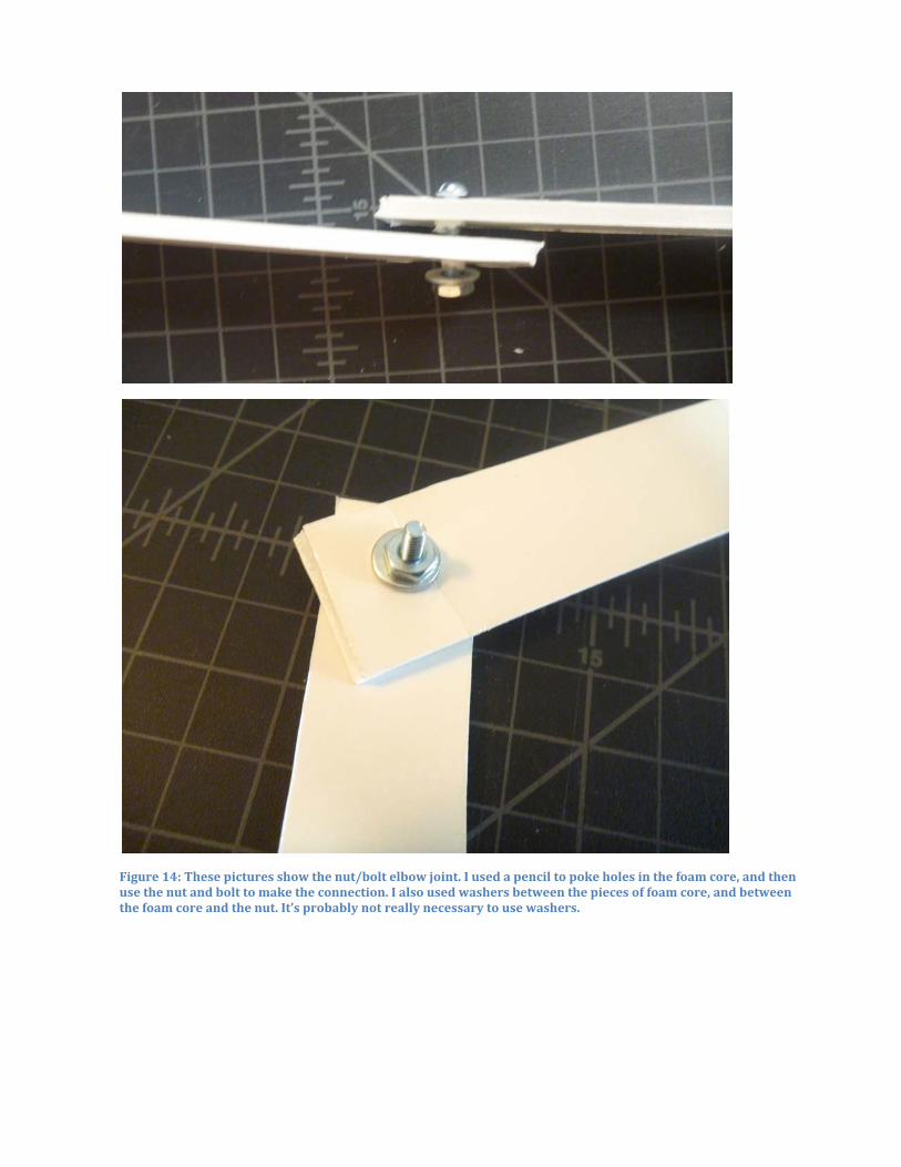
Figure 14: These pictures show the nut/bolt elbow joint. I used a pencil to poke holes in the foam core, and then use the nut and bolt to make the connection. I also used washers between the pieces of foam core, and between the foam core and the nut. It’s probably not really necessary to use washers.
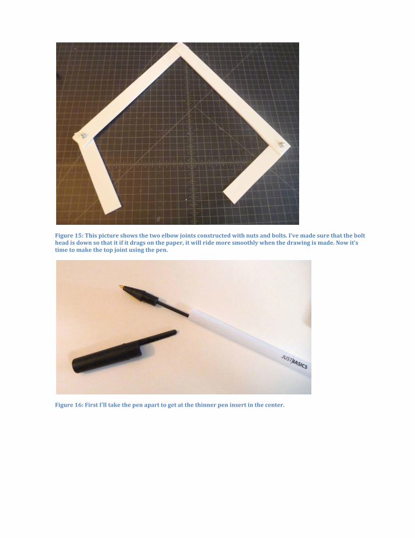
Figure 15: This picture shows the two elbow joints constructed with nuts and bolts. I’ve made sure that the bolt head is down so that it if it drags on the paper, it will ride more smoothly when the drawing is made. Now it’s time to make the top joint using the pen.
Figure 16: First I'll take the pen apart to get at the thinner pen insert in the center.
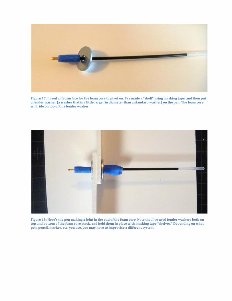
Figure 17: I need a flat surface for the foam core to pivot on. I've made a "shelf" using masking tape, and then put a fender washer (a washer that is a little larger in diameter than a standard washer) on the pen. The foam core will ride on top of this fender washer.
Figure 18: Here's the pen making a joint in the end of the foam core. Note that I’ve used fender washers both on top and bottom of the foam core stack, and held them in place with masking tape “shelves.” Depending on what pen, pencil, marker, etc. you use, you may have to improvise a different system.
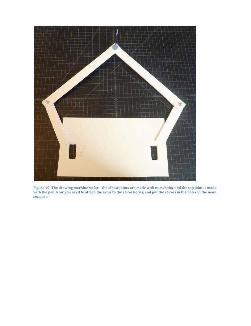
Figure 19: The drawing machine so far – the elbow joints are made with nuts/bolts, and the top joint is made with the pen. Now you need to attach the arms to the servo horns, and put the servos in the holes in the main support.
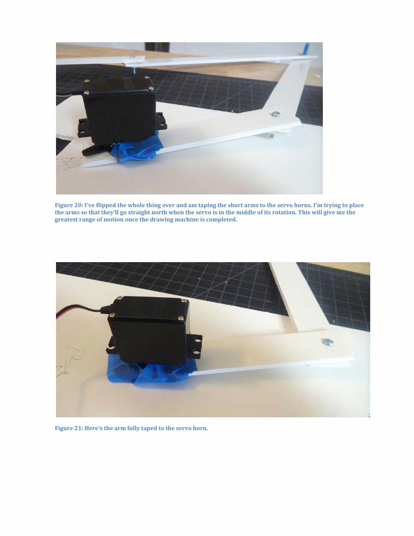
Figure 20: I've flipped the whole thing over and am taping the short arms to the servo horns. I'm trying to place the arms so that they’ll go straight north when the servo is in the middle of its rotation. This will give me the greatest range of motion once the drawing machine is completed.
Figure 21: Here's the arm fully taped to the servo horn.
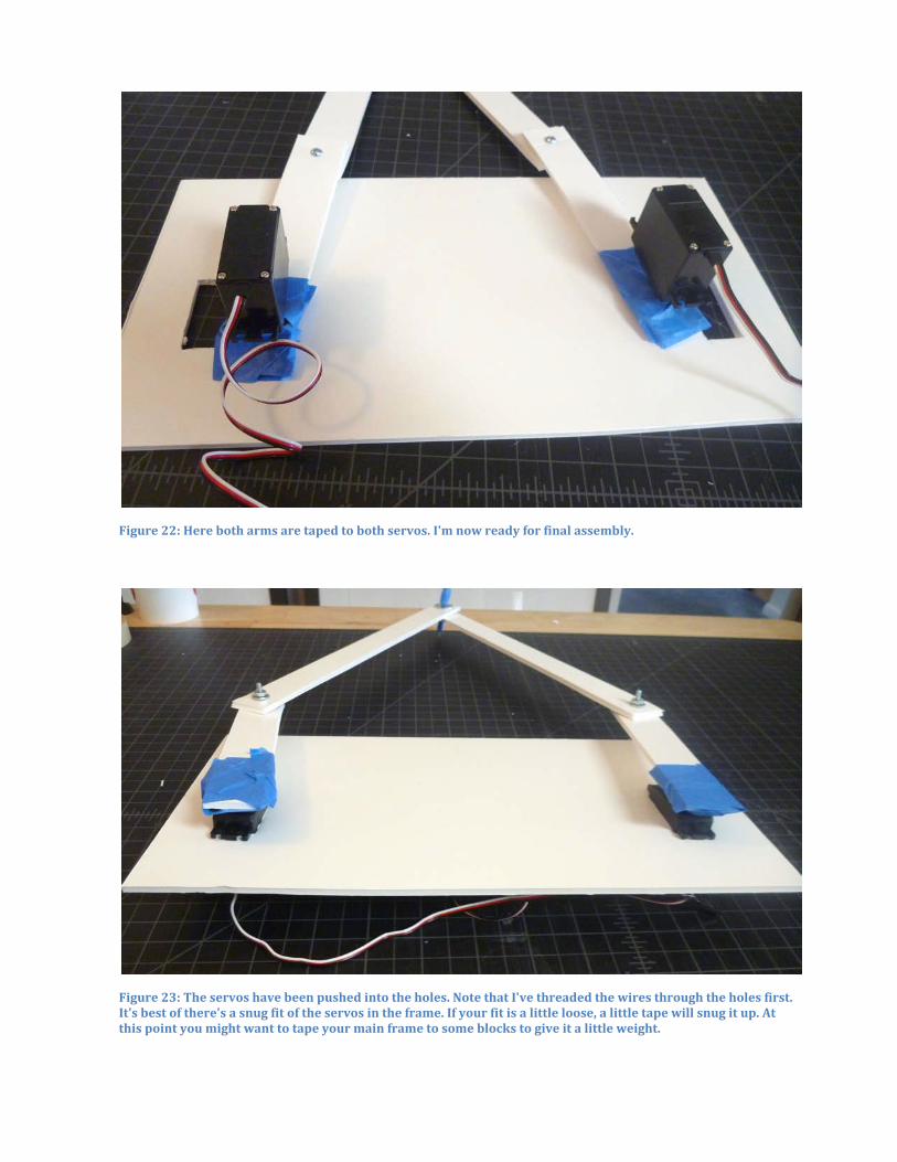
Figure 22: Here both arms are taped to both servos. I'm now ready for final assembly.
Figure 23: The servos have been pushed into the holes. Note that I've threaded the wires through the holes first. It's best of there's a snug fit of the servos in the frame. If your fit is a little loose, a little tape will snug it up. At this point you might want to tape your main frame to some blocks to give it a little weight.
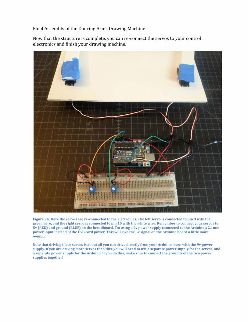
Final Assembly of the Dancing Arms Drawing Machine
Now that the structure is complete, you can re-‐connect the servos to your control electronics and finish your drawing machine.
Figure 24: Here the servos are re-connected to the electronics. The left servo is connected to pin 9 with the green wire, and the right servo is connected to pin 10 with the white wire. Remember to connect your servos to 5v (RED) and ground (BLUE) on the breadboard. I’m using a 9v power supply connected to the Arduino’s 2.1mm power input instead of the USB cord power. This will give the 5v signal on the Arduino board a little more oomph.
Note that driving these servos is about all you can drive directly from your Arduino, even with the 9v power supply. If you are driving more servos than this, you will need to use a separate power supply for the servos, and a separate power supply for the Arduino. If you do this, make sure to connect the grounds of the two power supplies together!
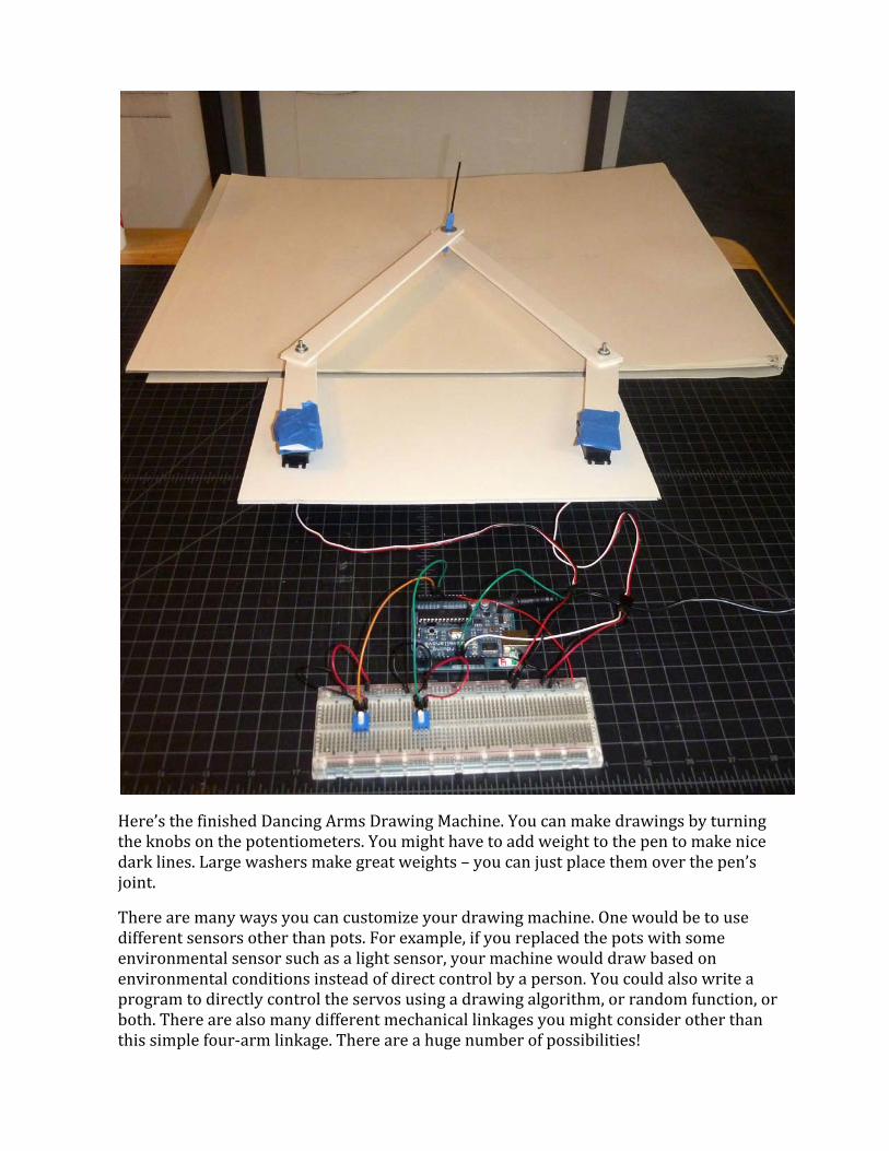
Here’s the finished Dancing Arms Drawing Machine. You can make drawings by turning the knobs on the potentiometers. You might have to add weight to the pen to make nice dark lines. Large washers make great weights – you can just place them over the pen’s joint.
There are many ways you can customize your drawing machine. One would be to use different sensors other than pots. For example, if you replaced the pots with some environmental sensor such as a light sensor, your machine would draw based on environmental conditions instead of direct control by a person. You could also write a program to directly control the servos using a drawing algorithm, or random function, or both. There are also many different mechanical linkages you might consider other than this simple four-‐arm linkage. There are a huge number of possibilities!
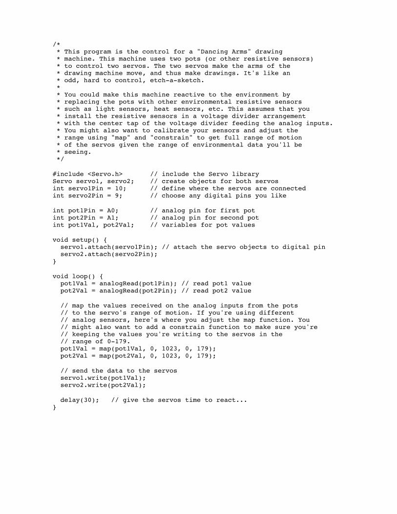
/* * This program is the control for a "Dancing Arms" drawing * machine. This machine uses two pots (or other resistive sensors) * to control two servos. The two servos make the arms of the * drawing machine move, and thus make drawings. It's like an * odd, hard to control, etch-a-sketch. * * You could make this machine reactive to the environment by * replacing the pots with other environmental resistive sensors * such as light sensors, heat sensors, etc. This assumes that you * install the resistive sensors in a voltage divider arrangement * with the center tap of the voltage divider feeding the analog inputs. * You might also want to calibrate your sensors and adjust the * range using "map" and "constrain" to get full range of motion * of the servos given the range of environmental data you'll be * seeing. */
#include <Servo.h> // include the Servo library Servo servo1, servo2; // create objects for both servos int servo1Pin = 10; // define where the servos are connected int servo2Pin = 9; // choose any digital pins you like
int pot1Pin = A0; // analog pin for first pot int pot2Pin = A1; // analog pin for second pot int pot1Val, pot2Val; // variables for pot values
void setup() { servo1.attach(servo1Pin); // attach the servo objects to digital pin servo2.attach(servo2Pin); }
void loop() { pot1Val = analogRead(pot1Pin); // read pot1 value pot2Val = analogRead(pot2Pin); // read pot2 value
// map the values received on the analog inputs from the pots // to the servo's range of motion. If you're using different // analog sensors, here's where you adjust the map function. You // might also want to add a constrain function to make sure you're // keeping the values you're writing to the servos in the // range of 0-179. pot1Val = map(pot1Val, 0, 1023, 0, 179); pot2Val = map(pot2Val, 0, 1023, 0, 179);
// send the data to the servos servo1.write(pot1Val); servo2.write(pot2Val);
delay(30); // give the servos time to react... }

This drawing machine is a simple project, but one that demonstrates a large number of physical computing concepts. These are just a few of those concepts:
• The project demonstrates the control of physical movement by a program. The program sends signals to the servos using pulse width modulation to tell the servos what angular position they should assume. The Arduino Servo.h library handles the details, but the basic concept is that by driving signals to a digital output pin your program can cause things to move physically.
• The pots are a good example of external sensors providing information to a program. Programs need inputs to provide data to be processed. In this case the inputs are real-‐time environmental inputs that are sampled by the program.
• The environmental condition being sensed here is the position of the knob, but this extends naturally to a wide range of environmental sensors, especially so-‐called “resistive sensors.” These are sensors that change their resistance in response to environmental conditions such as light, heat, movement, distance, etc.
• This project involves simple electronics concepts such as power and ground being required for electronic and electromechanical components. As a side note it can bring up topics such as power and current limits, and using multiple power supplies.
• The controller introduces the “solderless breadboard” as a prototyping substrate for electronics. These breadboards are commonly used to quickly assemble electronics for testing or debugging. By poking wires in the breadboards, electrical connections can be made and modified quickly and easily.
• The control program running on the Arduino demonstrates a “reactive programming” approach to algorithm design. The “loop” program in the Arduino programming environment (previous page) is an endless loop. Each time through the loop the environmental sensors (pots) are sampled to get their new values. Those values are interpolated (mapped) to the desired range, and then used to control the position of the servos. Each time through the loop, the control program reacts to the environmental conditions by causing some activity in the outputs.
• This project also demonstrates the strong connection that can exist between technology and the arts. This drawing machine will not make masterpieces, but it does demonstrate the basic concepts of how physical computing can be used to create kinetic sculptures. Imagine a more complex drawing machine, or a room full of simple drawing machines reacting to environmental conditions. That could be a really compelling art piece. This can help CS students see a very different application domain for computing, and can also help art students understand the possibilities of computer control in their art practice.