drawing a site plan

2
DRAWING A SITE PLAN All drawings shall conform to the following requirements. (1) Sheet size Preferred sizes are 11"x17", 18"x24", or 24"x36" An 8½"x11" site plan is acceptable only if all information can be shown at a legible and reproducible scale. One 8 ½"x11" reduced copy is required for recording by the Auditor for Land Use Permits. We must receive at least one site plan at or reduced to 8½“x11” or 11”x17” (2) Title Block Locate the following information on the right hand or bottom margin of all sheets: (11) Adjacent Roads Locate and label the existing roads or rights of way, both county and private. Show centerlines. (12) Spot Elevations and Topography Show surface elevations at each corner of the site and at each corner of the structure base. Where any portion of the parcel has a slope that exceeds 1:10, show existing and proposed contours at 5-foot intervals. (13) Show location of Water Supply, Service lines and Storage Tanks Include zones of protection for well, and zones of protection for any well on adjoining property that extends across property boundaries. Also see item 7 for additional requirements. (14) Show location of all Sewage Disposal Systems Include location of all test holes for sewage disposal permits and the general area and layout planned for the sewage disposal system. If the system is built, show as built. (15) Water Bodies, Wetlands, and Drainage Show all ponds, wetlands, wetland buffers, streams, and bodies of water. Calculate the total sf that will be disturbed during your project, including site preparation. For Shoreline Parcels The remaining items are required to be shown on the site plan if any portion of the proposed construction is located within 200’ of the shoreline (O.H.W.M.). (16) Ordinary High Water Mark (O.H.W.M.) Must be shown for all shoreline parcels. (17) Top and Toe of Bank Show top and toe of bank or berm. (18) Setback from Top of Bank Show distance from the top of the bank to the seaward face of the structure(s). To be measured at a right angle from the top of the bank or berm. (19) 200’ Shoreline Jurisdiction Show a line marking 200 feet from Ordinary High Water Mark. This line should follow the contour of the shoreline. (20) Tree Plan – Show species and trunk diameter for all existing trees that exceed 3- inches in diameter at 4-feet above the ground located within the 200’ shoreline area. Also identify any trees that you will be removing in the future. (21) Lot Width – Indicate lot width at seaward face of building. In addition you will need to provide photographs taken from the shoreline toward the project and from the project to the shoreline. Owner’s Name Date Owner’s Address Site Address Page Number Tax Parcel Number Lot Description Drawing Title Drawing Scale Revision Date & Number Name, Address & Phone number of person preparing drawings (3) Scale All site plans should be drawn to a standard Engineering scale. Indicate scale with bar symbol for plan reduction integrity. Site drawings are preferred to be at a scale of 1” = 20’, 30’, 40’, or 50’. Scales of 1” = 100’ or 200’ should only be used for very large parcels, and then a smaller scale drawing should also be submitted to provide greater detail of the area where new work is proposed. (4) North Arrow Include on all site and site-related drawings (i.e., vicinity map, detail enlargements, floor plan, etc.). (5) Property Lines Show the location and dimension of all property lines. (6) Easements Show location for all existing and proposed utility, open space, drainage, and access easements and/or private roads; draw to scale and accurately dimension. (7) Existing and Proposed Structures Show location, dimensions (including height), and use of all existing and proposed buildings and structures on the site, include number of rooms and bedrooms; show distances to EACH property line from the furthest most projection of the structure, including overhangs and decks. All setbacks are measured to the furthest most projection of any structure, including overhangs and decks. (8) Adjacent Buildings, Wells, and Septic Systems When your building, well or septic system is within 50 feet of any adjacent property line, you must show all buildings, septic systems and well locations on the adjacent parcel that are located within 50’ of the property line. Show distances from the adjacent property line to the neighboring structures. (9) Setbacks Show applicable minimum setbacks to ALL property lines and to the center- line of ALL adjacent roads. (10) Driveways and Parking Show location of on-site driveways and parking, and square footage of all existing and proposed impervious surfaces. N:\FORMS, LISTS & HANDOUTS\Building Forms\Individual Forms\Drawings & Instructions\DwgSitePlan_inst.doc IN ADDITION, A DRAINAGE PLAN MUST BE SUBMITTED WITH THE BUILDING PERMIT APPLICATION WHEN REQUIRED BY SAN JUAN COUNTY CODE SECTION 18.60.070 .

Upload: others

Post on 27-Jan-2022

3 views

Category:

Documents


0 download

TRANSCRIPT

DRAWING A SITE PLAN

All drawings shall conform to the following requirements.

(1) Sheet size – Preferred sizes are 11"x17", 18"x24", or 24"x36" An 8½"x11" site plan is acceptable only if all information can be shown at a legible and reproducible scale. One 8 ½"x11" reduced copy is required for recording by the Auditor for Land Use Permits. We must receive at least one site plan at or reduced to 8½“x11” or 11”x17”

(2) Title Block – Locate the following information on the right hand or bottom margin of all sheets:

(11) Adjacent Roads – Locate and label the existing roads or rights of way, both county and private. Show centerlines.

(12) Spot Elevations and Topography – Show surface elevations at each corner of the site and at each corner of the structure base. Where any portion of the parcel has a slope that exceeds 1:10, show existing and proposed contours at 5-foot intervals.

(13) Show location of Water Supply, Service lines and Storage Tanks – Include zones of protection for well, and zones of protection for any well on adjoining property that extends across property boundaries. Also see item 7 for additional requirements.

(14) Show location of all Sewage Disposal Systems – Include location of all test holes for sewage disposal permits and the general area and layout planned for the sewage disposal system. If the system is built, show as built.

(15) Water Bodies, Wetlands, and Drainage – Show all ponds, wetlands, wetland buffers, streams, and bodies of water. Calculate the total sf that will be disturbed during your project, including site preparation.

For Shoreline Parcels The remaining items are required to be shown on the site plan if any portion of the proposed construction is located within 200’ of the shoreline (O.H.W.M.).

(16) Ordinary High Water Mark (O.H.W.M.) – Must be shown for all shoreline parcels.

(17) Top and Toe of Bank – Show top and toe of bank or berm.

(18) Setback from Top of Bank – Show distance from the top of the bank to the seaward face of the structure(s). To be measured at a right angle from the top of the bank or berm.

(19) 200’ Shoreline Jurisdiction – Show a line marking 200 feet from Ordinary High Water Mark. This line should follow the contour of the shoreline.

(20) Tree Plan – Show species and trunk diameter for all existing trees that exceed 3- inches in diameter at 4-feet above the ground located within the 200’ shoreline area. Also identify any trees that you will be removing in the future.

(21) Lot Width – Indicate lot width at seaward face of building. In addition you will need to provide photographs taken from the shoreline toward the project and from the project to the shoreline.

Owner’s Name Date Owner’s Address Site Address Page Number

Tax Parcel Number Lot Description Drawing Title Drawing Scale Revision Date & Number

Name, Address & Phone number of person preparing drawings

(3) Scale – All site plans should be drawn to a standard Engineering scale. Indicate scale with bar symbol for plan reduction integrity. Site drawings are preferred to be at a scale of 1” = 20’, 30’, 40’, or 50’. Scales of 1” = 100’ or 200’ should only be used for very large parcels, and then a smaller scale drawing should also be submitted to provide greater detail of the area where new work is proposed.

(4) North Arrow – Include on all site and site-related drawings (i.e., vicinity map, detail enlargements, floor plan, etc.).

(5) Property Lines – Show the location and dimension of all property lines.

(6) Easements – Show location for all existing and proposed utility, open space, drainage, and access easements and/or private roads; draw to scale and accurately dimension.

(7) Existing and Proposed Structures – Show location, dimensions (including height), and use of all existing and proposed buildings and structures on the site, include number of rooms and bedrooms; show distances to EACH property line from the furthest most projection of the structure, including overhangs and decks. All setbacks are measured to the furthest most projection of any structure, including overhangs and decks.

(8) Adjacent Buildings, Wells, and Septic Systems – When your building, well or septic system is within 50 feet of any adjacent property line, you must show all buildings, septic systems and well locations on the adjacent parcel that are located within 50’ of the property line. Show distances from the adjacent property line to the neighboring structures.

(9) Setbacks – Show applicable minimum setbacks to ALL property lines and to the center- line of ALL adjacent roads.

(10) Driveways and Parking – Show location of on-site driveways and parking, and square footage of all existing and proposed impervious surfaces.

N:\FORMS, LISTS & HANDOUTS\Building Forms\Individual Forms\Drawings & Instructions\DwgSitePlan_inst.doc

IN ADDITION, A DRAINAGE PLAN MUST BE SUBMITTED WITH THE BUILDING PERMIT APPLICATION WHEN REQUIRED BY

SAN JUAN COUNTY CODE SECTION 18.60.070 .

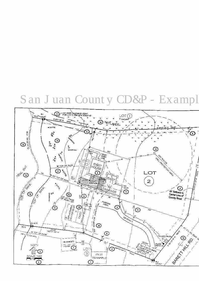
San Juan County CD&P - Example