draft - upm
TRANSCRIPT
DR
AFT
The four towers of theCuatro Torres Business Area
of MadridMartínez Pañeda, Miguel
Keywords: Structure, Madrid, Cuatro Torres Business Area, tall buildings, TorreBankia, Torre PwC, Torre Cristal, Torre Espacio.
Abstract
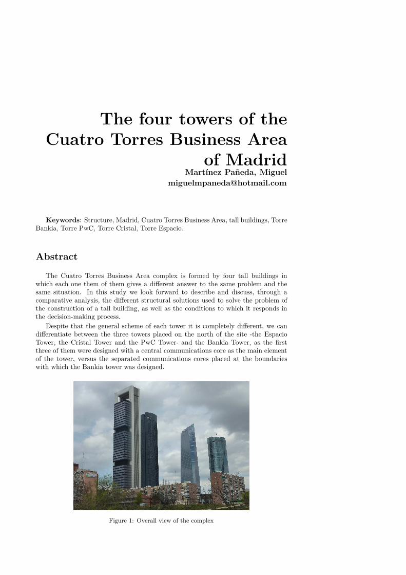
The Cuatro Torres Business Area complex is formed by four tall buildings inwhich each one them of them gives a different answer to the same problem and thesame situation. In this study we look forward to describe and discuss, through acomparative analysis, the different structural solutions used to solve the problem ofthe construction of a tall building, as well as the conditions to which it responds inthe decision-making process.
Despite that the general scheme of each tower it is completely different, we candifferentiate between the three towers placed on the north of the site -the EspacioTower, the Cristal Tower and the PwC Tower- and the Bankia Tower, as the firstthree of them were designed with a central communications core as the main elementof the tower, versus the separated communications cores placed at the boundarieswith which the Bankia tower was designed.
Figure 1: Overall view of the complex
DR
AFT
1 Introduction
The Four Towers Business Area (CTBA) is located in the extension of the axis ofPaseo de la Castellana, on the site of the former Real Madrid Sport Complex. Thecomplex consists of four tall buildings 250 meters high that have become the newtallest buildings in Spain. The previous highest building in Madrid was the PicassoTower, 100 meters shorter, and in Spain it was the Gran Hotel Bali, from Benidorm,that is 65 meters shorter than the towers of the CTBA. As the four of them arelocated on the same site and are devoted mostly to offices, they show us differentways of facing the same problem.
The specificity of tall buildings
Tall buildings have the particularity that, from a certain height, the horizontalforces play a much more important role than the gravity loads in the design of thestructure. The behavior of a tall building against the wind forces could be resembled tothe behavior of a cantilever fixed on the ground, with the flexural moments producedby the wind load as the main stresses to resist.
In tall buildings, the critical condition of the structure is the movement that thewind produces in the top of the tower. Not just for the damage that the horizontalmovements can produce to the tower, if not because of the accelerations, becauseof the discomfort that could mean for the users the perception of the movements ofthe building. Thus, to optimize the structure of a tower the structural mass shouldbe located on the boundaries, so that the tower gains more inertia against the hor-izontal bending forces. At the same time, the elements in charge of resisting thehorizontal stresses should receive enough gravity load so they could work better inflexo-compression. The basic optimal shape of a tower would be like the shape of achimney, with all its structural mass in the boundary and receiving all the gravityloads.
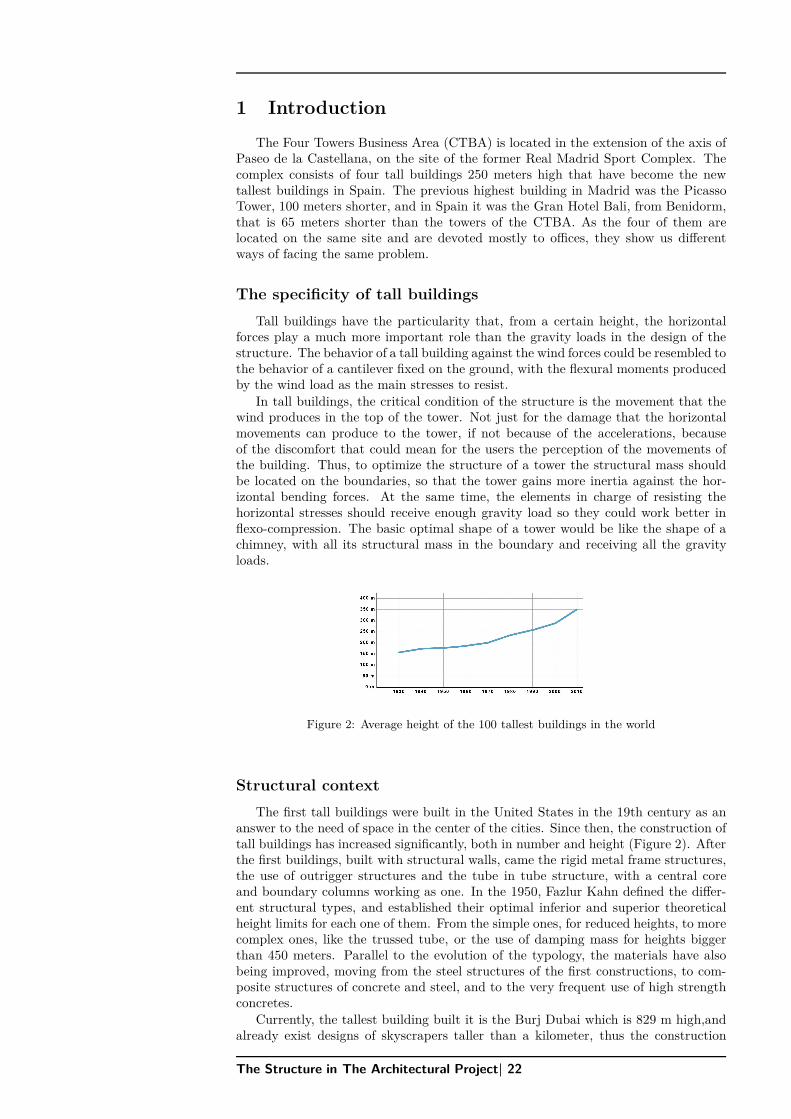
Figure 2: Average height of the 100 tallest buildings in the world
Structural context
The first tall buildings were built in the United States in the 19th century as ananswer to the need of space in the center of the cities. Since then, the construction oftall buildings has increased significantly, both in number and height (Figure 2). Afterthe first buildings, built with structural walls, came the rigid metal frame structures,the use of outrigger structures and the tube in tube structure, with a central coreand boundary columns working as one. In the 1950, Fazlur Kahn defined the differ-ent structural types, and established their optimal inferior and superior theoreticalheight limits for each one of them. From the simple ones, for reduced heights, to morecomplex ones, like the trussed tube, or the use of damping mass for heights biggerthan 450 meters. Parallel to the evolution of the typology, the materials have alsobeing improved, moving from the steel structures of the first constructions, to com-posite structures of concrete and steel, and to the very frequent use of high strengthconcretes.
Currently, the tallest building built it is the Burj Dubai which is 829 m high,andalready exist designs of skyscrapers taller than a kilometer, thus the construction
The Structure in The Architectural Project| 22
DR
AFT
of 250 m high tall buildings, like in this case, has become an usual situation ininternational context.
2 Four Towers Business Area (CTBA)
Espacio Tower
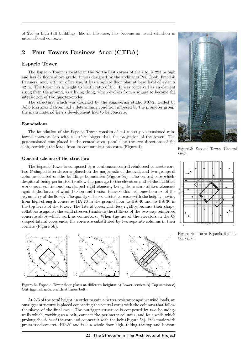
The Espacio Tower is located in the North-East corner of the site, is 223 m highand has 57 floors above grade. It was designed by the architects Pei, Cobb, Freed &Partners, and, with an office use, it has a square floor plan at base level of 42 m x42 m. The tower has a height to width ratio of 5.3. It was conceived as an elementrising from the ground, as a living thing, which evolves from a square to become theintersection of two quarter-circles.
Figure 3: Espacio Tower. Generalview.
The structure, which was designed by the engineering studio MC-2, leaded byJulio Martínez Calzón, had a determining condition imposed by the promoter group:the main material for its development had to be concrete.
Foundations
The foundation of the Espacio Tower consists of a 4 meter post-tensioned rein-forced concrete slab with a surface bigger than the projection of the tower. Thepos-tensioned was placed in the central area, parallel to the two directions of theslab, receiving the loads from its communications cores (Figure 4).
Figure 4: Torre Espacio founda-tions plan.
General scheme of the structure
The Espacio Tower is composed by a continuous central reinforced concrete core,two C-shaped laterals cores placed on the major axis of the oval, and two groups ofcolumns located on the buildings boundaries (Figure 5a). The central core which,despite of being perforated to allow the passage to the elevators and of the facilities,works as a continuous box-shaped rigid element, being the main stiffness elementsagainst the forces of wind, flexion and torsion (caused this last ones because of theasymmetry of the floor). The quality of the concrete decreases with the height, movingfrom high-strength concretes HA-70 in the ground floor to HA-40 and to HA-30 inthe top levels of the tower. The lateral cores, with less rigidity because their shape,collaborate against the wind stresses thanks to the stiffness of the two-way reinforcedconcrete slabs which work as connectors. When the use of the elevators in the C-shaped lateral cores ends, the cores are substituted by two separate columns in theircorners (Figure 5b).
Figure 5: Espacio Tower floor plans at different heights: a) Lower section b) Top section c)Outrigger structure with stiffness belt.
At 2/3 of the total height, in order to gain a better resistance against wind loads, anoutrigger structure is placed connecting the central cores with the columns that followthe shape of the final oval. The outrigger structure is composed by two boundarywalls which, working as a belt, connect the perimeter columns, and four walls whichprolong the sides of the core and connect it with the belt (Figure 5c). It is made withprestressed concrete HP-80 and it is a whole floor high, taking the top and bottom
23| The Structure in The Architectural Project
DR
AFT
floors, 43 cm thick, as their chords, being therefore strengthen with more density ofreinforcements and prestressed bars.
Structural elements
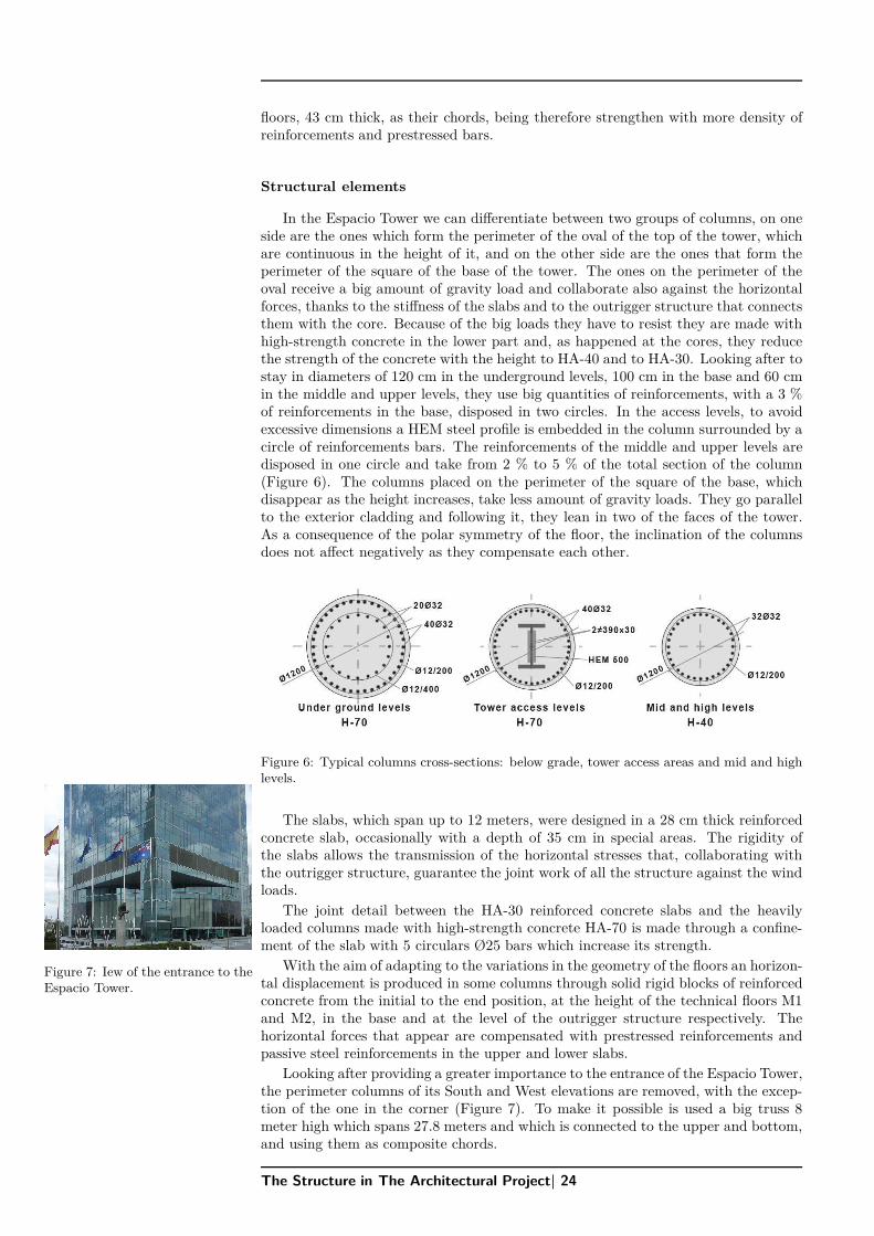
In the Espacio Tower we can differentiate between two groups of columns, on oneside are the ones which form the perimeter of the oval of the top of the tower, whichare continuous in the height of it, and on the other side are the ones that form theperimeter of the square of the base of the tower. The ones on the perimeter of theoval receive a big amount of gravity load and collaborate also against the horizontalforces, thanks to the stiffness of the slabs and to the outrigger structure that connectsthem with the core. Because of the big loads they have to resist they are made withhigh-strength concrete in the lower part and, as happened at the cores, they reducethe strength of the concrete with the height to HA-40 and to HA-30. Looking after tostay in diameters of 120 cm in the underground levels, 100 cm in the base and 60 cmin the middle and upper levels, they use big quantities of reinforcements, with a 3 %of reinforcements in the base, disposed in two circles. In the access levels, to avoidexcessive dimensions a HEM steel profile is embedded in the column surrounded by acircle of reinforcements bars. The reinforcements of the middle and upper levels aredisposed in one circle and take from 2 % to 5 % of the total section of the column(Figure 6). The columns placed on the perimeter of the square of the base, whichdisappear as the height increases, take less amount of gravity loads. They go parallelto the exterior cladding and following it, they lean in two of the faces of the tower.As a consequence of the polar symmetry of the floor, the inclination of the columnsdoes not affect negatively as they compensate each other.
Figure 6: Typical columns cross-sections: below grade, tower access areas and mid and highlevels.
The slabs, which span up to 12 meters, were designed in a 28 cm thick reinforcedconcrete slab, occasionally with a depth of 35 cm in special areas. The rigidity ofthe slabs allows the transmission of the horizontal stresses that, collaborating withthe outrigger structure, guarantee the joint work of all the structure against the windloads.
The joint detail between the HA-30 reinforced concrete slabs and the heavilyloaded columns made with high-strength concrete HA-70 is made through a confine-ment of the slab with 5 circulars Ø25 bars which increase its strength.
Figure 7: Iew of the entrance to theEspacio Tower.
With the aim of adapting to the variations in the geometry of the floors an horizon-tal displacement is produced in some columns through solid rigid blocks of reinforcedconcrete from the initial to the end position, at the height of the technical floors M1and M2, in the base and at the level of the outrigger structure respectively. Thehorizontal forces that appear are compensated with prestressed reinforcements andpassive steel reinforcements in the upper and lower slabs.
Looking after providing a greater importance to the entrance of the Espacio Tower,the perimeter columns of its South and West elevations are removed, with the excep-tion of the one in the corner (Figure 7). To make it possible is used a big truss 8meter high which spans 27.8 meters and which is connected to the upper and bottom,and using them as composite chords.
The Structure in The Architectural Project| 24
DR
AFT
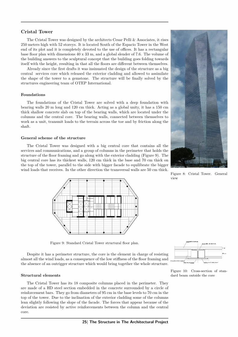
Cristal Tower
The Cristal Tower was designed by the architects Cesar Pelli & Associates, it rises250 meters high with 52 storeys. It is located South of the Espacio Tower in the Westend of its plot and it is completely devoted to the use of offices. It has a rectangularbase floor plan with dimensions 40 x 33 m, and a global slender of 7.6. The volume ofthe building answers to the sculptural concept that the building goes folding towardsitself with the height, resulting in that all the floors are different between themselves.
Already since the first drafts it was insinuated the design of the structure as a bigcentral services core which released the exterior cladding and allowed to assimilatethe shape of the tower to a gemstone. The structure will be finally solved by thestructures engineering team of OTEP International.
Figure 8: Cristal Tower. Generalview
Foundations
The foundations of the Cristal Tower are solved with a deep foundation withbearing walls 20 m long and 120 cm thick. Acting as a global unity, it has a 150 cmthick shallow concrete slab on top of the bearing walls, which are located under thecolumns and the central core. The bearing walls, connected between themselves towork as a unit, transmit loads to the terrain across the toe and by friction along theshaft.
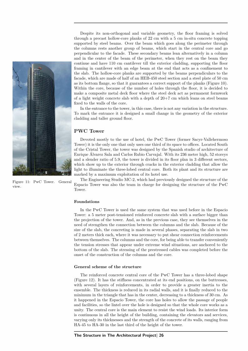
General scheme of the structure
The Cristal Tower was designed with a big central core that contains all theservices and communications, and a group of columns in the perimeter that holds thestructure of the floor framing and go along with the exterior cladding (Figure 9). Thebig central core has its thickest walls, 120 cm thick in the base and 70 cm thick onthe top of the tower, parallel to the side with bigger facade to equilibrate the biggerwind loads that receives. In the other direction the transversal walls are 50 cm thick.
Figure 9: Standard Cristal Tower structural floor plan.
Despite it has a perimeter structure, the core is the element in charge of resistingalmost all the wind loads, as a consequence of the low stiffness of the floor framing andthe absence of an outrigger structure which would bring together the whole structure.
Figure 10: Cross-section of stan-dard beam outside the coreStructural elements
The Cristal Tower has its 18 composite columns placed in the perimeter. Theyare made of a HD steel section embedded in the concrete surrounded by a circle ofreinforcement bars. They go from diameters of 95 cm in the base levels to 70 cm in thetop of the tower. Due to the inclination of the exterior cladding some of the columnslean slightly following the slope of the facade. The forces that appear because of thedeviation are resisted by active reinforcements between the column and the centralcore.
25| The Structure in The Architectural Project
DR
AFT
Despite its non-orthogonal and variable geometry, the floor framing is solvedthrough a precast hollow-core planks of 22 cm with a 5 cm in-situ concrete toppingsupported by steel beams. Over the beam which goes along the perimeter throughthe columns rests another group of beams, which start in the central core and goperpendicular to the facade. These secondary beams lean alternatively in a columnand in the center of the beam of the perimeter, when they rest on the beam theycontinue and have 110 cm cantilever till the exterior cladding, supporting the floorframing in cantilever with an edge beam at the end that acts as a confinement tothe slab. The hollow-core planks are supported by the beams perpendiculars to thefacade, which are made of half of an HEB-450 steel section and a steel plate of 50 cmas its bottom flange, so that it guarantees a correct support of the planks (Figure 10).Within the core, because of the number of holes through the floor, it is decided tomake a composite metal deck floor where the steel deck act as permanent formworkof a light weight concrete slab with a depth of 20+7 cm which leans on steel beamsfixed to the walls of the core.
In the entrance to the tower, in this case, there is not any variation in the structure.To mark the entrance it is designed a small change in the geometry of the exteriorcladding and taller ground floor.
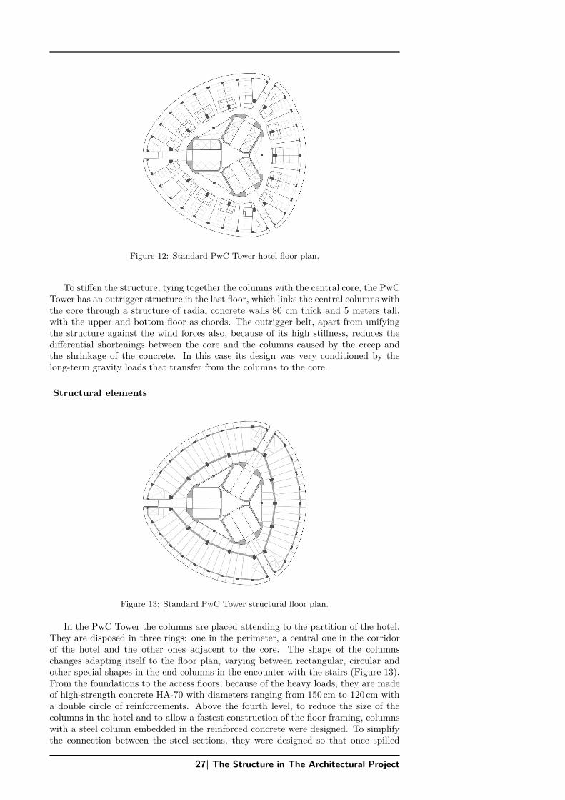
PWC Tower
Devoted mostly to the use of hotel, the PwC Tower (former Sacyr-VallehermosoTower) it is the only one that only uses one third of its space to offices. Located Southof the Cristal Tower, the tower was designed by the Spanish studio of architecture ofEnrique Álvarez Sala and Carlos Rubio Carvajal. With its 236 meter high, 52 storeysand a slender ratio of 5.9, the tower is divided in its floor plan in 3 different sectors,which show up to the exterior through cracks in the exterior cladding that allow thelight to illuminate the three-lobed central core. Both its plant and its structure aremarked by a maximum exploitation of its hotel use.
Figure 11: PwC Tower. Generalview.
The Engineering Studio MC-2, which had previously designed the structure of theEspacio Tower was also the team in charge for designing the structure of the PwCTower.
Foundations
In the PwC Tower is used the same system that was used before in the EspacioTower: a 5 meter post-tensioned reinforced concrete slab with a surface bigger thanthe projection of the tower. And, as in the previous case, they see themselves in theneed of strengthen the connection between the columns and the slab. Because of thesize of the slab, the concreting is made in several phases, separating the slab in twoof 2 meters thick each, where it was necessary to put shear connection reinforcementsbetween themselves. The columns and the core, for being able to transfer convenientlythe tension stresses that appear under extreme wind situations, are anchored to thebottom of the slab. The stressing of the prestressed cables was completed before theonset of the construction of the columns and the core.
General scheme of the structure
The reinforced concrete central core of the PwC Tower has a three-lobed shape(Figure 12). It has the stiffness concentrated at its end positions, on the buttresses,with several layers of reinforcements, in order to provide a greater inertia to theensemble. The thickness is reduced in its radial walls, and it is finally reduced to theminimum in the triangle that has in the center, decreasing to a thickness of 30 cm. Asit happened in the Espacio Tower, the core has holes to allow the passage of peopleand facilities, so the lintel over the hole is designed so that the whole core works as aunity. The central core is the main element to resist the wind loads. Its interior formis continuous in all the height of the building, containing the elevators and services,varying only its thicknesses and the strength of the concrete of its walls, ranging fromHA-45 to HA-30 in the last third of the height of the tower.
The Structure in The Architectural Project| 26
DR
AFTFigure 12: Standard PwC Tower hotel floor plan.
To stiffen the structure, tying together the columns with the central core, the PwCTower has an outrigger structure in the last floor, which links the central columns withthe core through a structure of radial concrete walls 80 cm thick and 5 meters tall,with the upper and bottom floor as chords. The outrigger belt, apart from unifyingthe structure against the wind forces also, because of its high stiffness, reduces thedifferential shortenings between the core and the columns caused by the creep andthe shrinkage of the concrete. In this case its design was very conditioned by thelong-term gravity loads that transfer from the columns to the core.
Structural elements
Figure 13: Standard PwC Tower structural floor plan.
In the PwC Tower the columns are placed attending to the partition of the hotel.They are disposed in three rings: one in the perimeter, a central one in the corridorof the hotel and the other ones adjacent to the core. The shape of the columnschanges adapting itself to the floor plan, varying between rectangular, circular andother special shapes in the end columns in the encounter with the stairs (Figure 13).From the foundations to the access floors, because of the heavy loads, they are madeof high-strength concrete HA-70 with diameters ranging from 150 cm to 120 cm witha double circle of reinforcements. Above the fourth level, to reduce the size of thecolumns in the hotel and to allow a fastest construction of the floor framing, columnswith a steel column embedded in the reinforced concrete were designed. To simplifythe connection between the steel sections, they were designed so that once spilled
27| The Structure in The Architectural Project
DR
AFT
the concrete, the steel column does not receive any tension, resisting only the onesproduced by the wind during the construction process, as the steel construction goes3 floors ahead of the concreting. The perimeter reinforcements will be the ones incharge of resisting the tensions that could appear in the columns.
Because of the higher loads, the location of holes, and columns with a largerdistance between them, the floors under level N04 are made with a solid reinforcedconcrete slab. Upwards level N04 the floor framing consists a composite structure ofsteel and concrete. It is designed a composite metal deck slab supported by compositebeams of steel profiles provided with shear studs. There are three rings of beams,bolted to the three rings of columns respectively. The radial joists rest over theexterior ring of beams and have a cantilever that supports the two layers of theexterior cladding. The exterior curved perimeter is solved with a border stiffnesselement which acts as an edge beam at the end of the slab, shaped like a steel coffin,is supported by the radial joists and acts as composite formwork of the concrete ofthe slab.
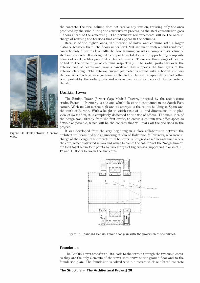
Bankia Tower
The Bankia Tower (former Caja Madrid Tower), designed by the architecturestudio Foster + Partners, is the one which closes the compound in its South-Eastcorner. With its 250 meters high and 42 storeys, is the tallest building in Spain andthe tenth of Europe. With a height to width ratio of 11, and dimensions in its planview of 53 x 43 m, it is completely dedicated to the use of offices. The main idea ofthe design was, already from the first drafts, to create a column free office space asflexible as possible, which will be the concept that will mark all the decisions in theproject.
Figure 14: Bankia Tower. Generalview.
It was developed from the very beginning in a close collaboration between thearchitectural team and the engineering studio of Halvorson & Partners, who were incharge of the design of the structure. The tower is designed as a “mega-frame” wherethe core, which is divided in two and which becomes the columns of the “mega-frame”,are tied together in four points by two groups of big trusses, supporting blocks of 11,12 and 11 floors between the two cores.
Figure 15: Standard Bankia Tower floor plan with the projection of the trusses.
Foundations
The Bankia Tower transfers all its loads to the terrain through the two main cores,as they are the only elements of the tower that arrive to the ground floor and to thefoundation plan. The foundation is solved with a 5 meters thick reinforced concrete
The Structure in The Architectural Project| 28
DR
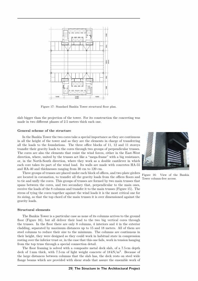
AFTFigure 17: Standard Bankia Tower structural floor plan.
slab bigger than the projection of the tower. For its construction the concreting wasmade in two different phases of 2.5 meters thick each one.
General scheme of the structure
In the Bankia Tower the two cores take a special importance as they are continuousin all the height of the tower and as they are the elements in charge of transferringall the loads to the foundations. The three office blocks of 11, 12 and 11 storeystransfer their gravity loads to the cores through two groups of perpendicular trusses.The cores are also the elements that resist the wind forces, either in the East-Westdirection, where, united by the trusses act like a “mega-frame” with a big resistance,or, in the North-South direction, where they work as a double cantilever in whicheach core takes its part of the wind load. Its walls are made with concretes HA-55and HA-40 and thicknesses ranging from 30 cm to 120 cm.
Figure 16: View of the BankiaTower column-free access.
Three groups of trusses are placed under each block of offices, and two plate girdersare located in coronation, to transfer all the gravity loads from the offices floors andto tie and unify the cores. This groups of trusses are formed by two main trusses thatspans between the cores, and two secondary that, perpendicular to the main ones,receive the loads of the 8 columns and transfer it to the main trusses (Figure 15). Thestress of tying the cores together against the wind loads it is the most critical one forits sizing, so that the top chord of the main trusses it is over dimensioned against thegravity loads.
Structural elements
The Bankia Tower is a particular case as none of its columns arrives to the groundfloor (Figure 16), but all deliver their load to the two big vertical cores throughthe trusses. In the floor there are only 8 columns, 4 interiors and 4 in the exteriorcladding, separated by maximum distances up to 15 and 18 meters. All of them aresteel columns to reduce their size to the minimum. The columns are continuous intheir height, they were designed so they could work in habitual state in compressionresting over the inferior trust or, in the case that this one fails, work in tension hangingfrom the top truss through a special connection detail.
The floor framing is solved with a composite metal deck slab, of a 7.5 cm depthdeck of 1 mm thick, with 7.5 cm of light weight concrete of 18 kN/m3. Because ofthe large distances between columns that the slab has, the deck rests on steel wideflange beams which are provided with shear studs that assure the ensemble work of
29| The Structure in The Architectural Project
DR
AFT
the slab. Towards North and South the slab has a 9 meters cantilever respect thecores, with a cantilever also in each corner as it does not have any columns, just the8 interiors in its central area (Figure 17). As a special case, over the technical floorsand to ensure a better acoustic insulation, the light weight concrete is substituted bynormal dense concrete and the layer of concrete is increased to 15 cm. In the facadeof each office block, to improve its behavior, a Vierendeel frame is formed with theexterior columns and the edge beams.
3 Comparison of the four solutions
Foundations
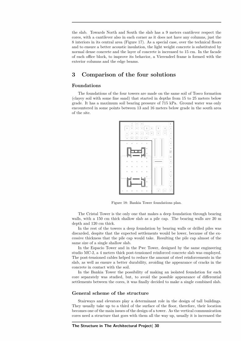
The foundations of the four towers are made on the same soil of Tosco formation(clayey soil with some fine sand) that started in depths from 15 to 25 meters belowgrade. It has a maximum soil bearing pressure of 715 kPa. Ground water was onlyencountered in some points between 13 and 16 meters below grade in the south areaof the site.
Figure 18: Bankia Tower foundations plan.
The Cristal Tower is the only one that makes a deep foundation through bearingwalls, with a 150 cm thick shallow slab as a pile cap. The bearing walls are 20 mdepth and 120 cm thick.
In the rest of the towers a deep foundation by bearing walls or drilled piles wasdiscarded, despite that the expected settlements would be lower, because of the ex-cessive thickness that the pile cap would take. Resulting the pile cap almost of thesame size of a single shallow slab.
In the Espacio Tower and in the Pwc Tower, designed by the same engineeringstudio MC-2, a 4 meters thick post-tensioned reinforced concrete slab was employed.The post-tensioned cables helped to reduce the amount of steel reinforcements in theslab, as well as ensure a better durability, avoiding the appearance of cracks in theconcrete in contact with the soil.
In the Bankia Tower the possibility of making an isolated foundation for eachcore separately was studied, but, to avoid the possible appearance of differentialsettlements between the cores, it was finally decided to make a single combined slab.
General scheme of the structure
Stairways and elevators play a determinant role in the design of tall buildings.They usually take up to a third of the surface of the floor, therefore, their locationbecomes one of the main issues of the design of a tower. As the vertical communicationcores need a structure that goes with them all the way up, usually it is increased the
The Structure in The Architectural Project| 30
DR
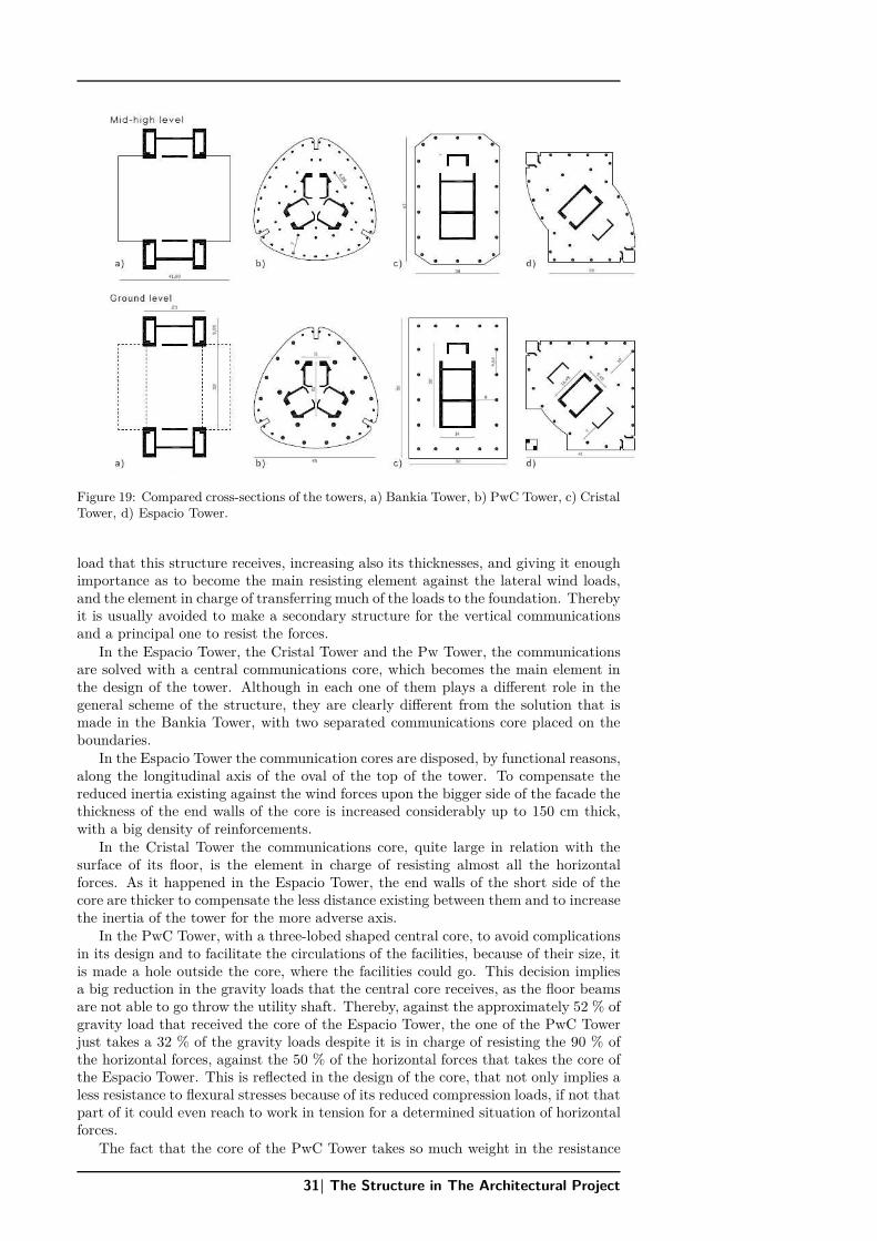
AFTFigure 19: Compared cross-sections of the towers, a) Bankia Tower, b) PwC Tower, c) Cristal
Tower, d) Espacio Tower.
load that this structure receives, increasing also its thicknesses, and giving it enoughimportance as to become the main resisting element against the lateral wind loads,and the element in charge of transferring much of the loads to the foundation. Therebyit is usually avoided to make a secondary structure for the vertical communicationsand a principal one to resist the forces.
In the Espacio Tower, the Cristal Tower and the Pw Tower, the communicationsare solved with a central communications core, which becomes the main element inthe design of the tower. Although in each one of them plays a different role in thegeneral scheme of the structure, they are clearly different from the solution that ismade in the Bankia Tower, with two separated communications core placed on theboundaries.
In the Espacio Tower the communication cores are disposed, by functional reasons,along the longitudinal axis of the oval of the top of the tower. To compensate thereduced inertia existing against the wind forces upon the bigger side of the facade thethickness of the end walls of the core is increased considerably up to 150 cm thick,with a big density of reinforcements.
In the Cristal Tower the communications core, quite large in relation with thesurface of its floor, is the element in charge of resisting almost all the horizontalforces. As it happened in the Espacio Tower, the end walls of the short side of thecore are thicker to compensate the less distance existing between them and to increasethe inertia of the tower for the more adverse axis.
In the PwC Tower, with a three-lobed shaped central core, to avoid complicationsin its design and to facilitate the circulations of the facilities, because of their size, itis made a hole outside the core, where the facilities could go. This decision impliesa big reduction in the gravity loads that the central core receives, as the floor beamsare not able to go throw the utility shaft. Thereby, against the approximately 52 % ofgravity load that received the core of the Espacio Tower, the one of the PwC Towerjust takes a 32 % of the gravity loads despite it is in charge of resisting the 90 % ofthe horizontal forces, against the 50 % of the horizontal forces that takes the core ofthe Espacio Tower. This is reflected in the design of the core, that not only implies aless resistance to flexural stresses because of its reduced compression loads, if not thatpart of it could even reach to work in tension for a determined situation of horizontalforces.
The fact that the core of the PwC Tower takes so much weight in the resistance
31| The Structure in The Architectural Project
DR
AFT
against the horizontal forces compared to the one of the Espacio Tower (been bothstructures designed by the same engineering team MC-2), is determined also by thelocation of the outrigger structure in the top level of the tower, versus its location at2/3 the height of the tower, its optimal position, that they have previously made inthe Espacio Tower. Although the contribution against the horizontal forces that theoutrigger structure makes in the PwC Tower is just of a 10 %, against the 19 % thattakes the one in the Espacio Tower, as all the plants are equal, and to avoid stoppingthe constructive process, in the PwC Tower was decided to place it in its top floor.
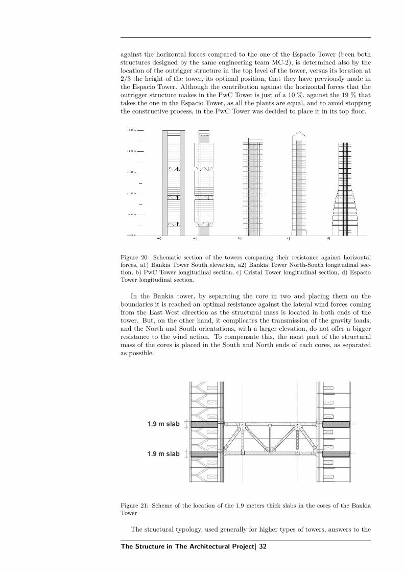
Figure 20: Schematic section of the towers comparing their resistance against horizontalforces, a1) Bankia Tower South elevation, a2) Bankia Tower North-South longitudinal sec-tion, b) PwC Tower longitudinal section, c) Cristal Tower longitudinal section, d) EspacioTower longitudinal section.
In the Bankia tower, by separating the core in two and placing them on theboundaries it is reached an optimal resistance against the lateral wind forces comingfrom the East-West direction as the structural mass is located in both ends of thetower. But, on the other hand, it complicates the transmission of the gravity loads,and the North and South orientations, with a larger elevation, do not offer a biggerresistance to the wind action. To compensate this, the most part of the structuralmass of the cores is placed in the South and North ends of each cores, as separatedas possible.
Figure 21: Scheme of the location of the 1.9 meters thick slabs in the cores of the BankiaTower
The structural typology, used generally for higher types of towers, answers to the
The Structure in The Architectural Project| 32
DR
AFT
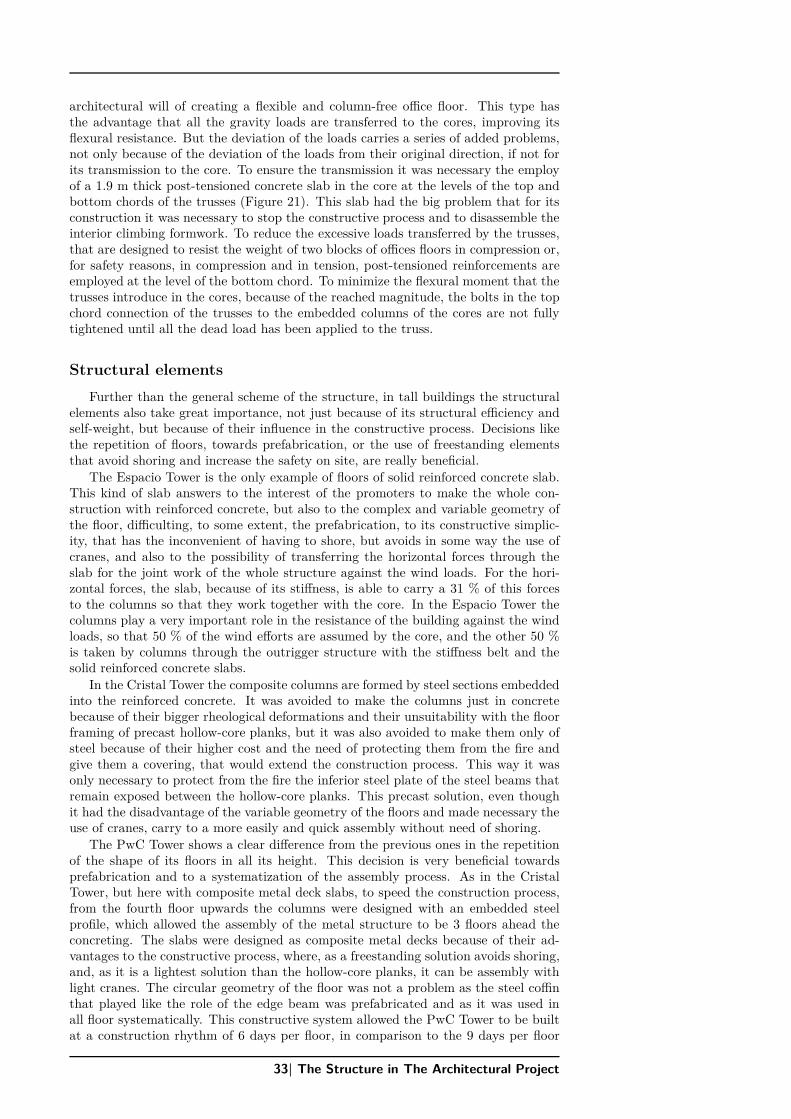
architectural will of creating a flexible and column-free office floor. This type hasthe advantage that all the gravity loads are transferred to the cores, improving itsflexural resistance. But the deviation of the loads carries a series of added problems,not only because of the deviation of the loads from their original direction, if not forits transmission to the core. To ensure the transmission it was necessary the employof a 1.9 m thick post-tensioned concrete slab in the core at the levels of the top andbottom chords of the trusses (Figure 21). This slab had the big problem that for itsconstruction it was necessary to stop the constructive process and to disassemble theinterior climbing formwork. To reduce the excessive loads transferred by the trusses,that are designed to resist the weight of two blocks of offices floors in compression or,for safety reasons, in compression and in tension, post-tensioned reinforcements areemployed at the level of the bottom chord. To minimize the flexural moment that thetrusses introduce in the cores, because of the reached magnitude, the bolts in the topchord connection of the trusses to the embedded columns of the cores are not fullytightened until all the dead load has been applied to the truss.
Structural elements
Further than the general scheme of the structure, in tall buildings the structuralelements also take great importance, not just because of its structural efficiency andself-weight, but because of their influence in the constructive process. Decisions likethe repetition of floors, towards prefabrication, or the use of freestanding elementsthat avoid shoring and increase the safety on site, are really beneficial.
The Espacio Tower is the only example of floors of solid reinforced concrete slab.This kind of slab answers to the interest of the promoters to make the whole con-struction with reinforced concrete, but also to the complex and variable geometry ofthe floor, difficulting, to some extent, the prefabrication, to its constructive simplic-ity, that has the inconvenient of having to shore, but avoids in some way the use ofcranes, and also to the possibility of transferring the horizontal forces through theslab for the joint work of the whole structure against the wind loads. For the hori-zontal forces, the slab, because of its stiffness, is able to carry a 31 % of this forcesto the columns so that they work together with the core. In the Espacio Tower thecolumns play a very important role in the resistance of the building against the windloads, so that 50 % of the wind efforts are assumed by the core, and the other 50 %is taken by columns through the outrigger structure with the stiffness belt and thesolid reinforced concrete slabs.
In the Cristal Tower the composite columns are formed by steel sections embeddedinto the reinforced concrete. It was avoided to make the columns just in concretebecause of their bigger rheological deformations and their unsuitability with the floorframing of precast hollow-core planks, but it was also avoided to make them only ofsteel because of their higher cost and the need of protecting them from the fire andgive them a covering, that would extend the construction process. This way it wasonly necessary to protect from the fire the inferior steel plate of the steel beams thatremain exposed between the hollow-core planks. This precast solution, even thoughit had the disadvantage of the variable geometry of the floors and made necessary theuse of cranes, carry to a more easily and quick assembly without need of shoring.
The PwC Tower shows a clear difference from the previous ones in the repetitionof the shape of its floors in all its height. This decision is very beneficial towardsprefabrication and to a systematization of the assembly process. As in the CristalTower, but here with composite metal deck slabs, to speed the construction process,from the fourth floor upwards the columns were designed with an embedded steelprofile, which allowed the assembly of the metal structure to be 3 floors ahead theconcreting. The slabs were designed as composite metal decks because of their ad-vantages to the constructive process, where, as a freestanding solution avoids shoring,and, as it is a lightest solution than the hollow-core planks, it can be assembly withlight cranes. The circular geometry of the floor was not a problem as the steel coffinthat played like the role of the edge beam was prefabricated and as it was used inall floor systematically. This constructive system allowed the PwC Tower to be builtat a construction rhythm of 6 days per floor, in comparison to the 9 days per floor
33| The Structure in The Architectural Project
DR
AFT
of the Espacio Tower. To protect the slabs against fire only the beams were coveredwith projected fire-proof mortar, as a supplementary reinforcement was placed on thebottom of the slabs ribs.
The Bankia Tower, following its architectural intentions of achieving a floor asdiaphanous as possible, was designed with a slab with the less possible number ofcolumns, resulting in distances up to 18 meters between their 8 columns. Because ofthis large distances between columns the composite metal deck slab only has 7.5 cmlight weight concrete of 18 kN/m3 and the steel beams are mostly designed with cam-bering, to compensate the self-weight of the slab. Even though this particularities toanswer in an ideal way to the architectural wills could become a problem, this is mini-mized thanks to the repetition of all floors along the tower, allowing the prefabricationand standardization of all elements.
In relation with the importance that takes, in tall buildings, the deformationsassociated to the creep and shrinkage of the concrete, the towers opt for differentsolutions.
At the Espacio Tower and the PwC Tower, both designed with concrete columnsand cores, the problem of the differential creep and shrinkage between them —whichtends to create differential deflections in the slabs—, is assumed by the outriggerstructure, that, because of its stiffness, avoids the appearing of differential shortenings.
In the Cristal Tower, as it has not got any outrigger structure that compensatesthe bigger settlements in the columns against the ones produced in the core, it isdecided to anticipate to those shortenings and increase the length of the columns ineach segment.
In the Bankia Tower, to equilibrate the big values of creep and shrinkage that hasthe concrete of the core versus the steel frames of the office blocks, relative displace-ments between the different blocks of offices were allowed through a special joint detailat the connection with each group of trusses, becoming the offices blocks independentand limiting the accumulation of stresses and differential movements to each block ofoffices separately.
4 Conclusions
The typology of towers of the Cuatro Torres Business Area, with heights up to250 meters and height to width ratios ranging from 5.3 to 11, offers several structuralalternatives. In this case, the most common choice was the central core with perimetercolumns. This solution was used in the Espacio Tower, in the Cristal Tower and inthe PwC Tower, although in each one of them plays a different role.
In the Espacio Tower and in the Cristal Tower the central cores, with a differentbehaviour in each one of them, answer to the interest of leaving free and continuousthe facade, as it becomes the image of the design and of the tower. In the PwC Towerthe central core answers more to the intention of allowing a maximum exploitationof the surface of the floor to the hotel use, releasing the surface of facade to this use.The Bankia Tower, looking forward to having a diaphanous office floor, was designwith a completely different typology, with two cores situated on the boundaries. Inall of them, whether in a greater or lesser extent, the main objectives of each towerare reflected on the choice of its structural typology.
Tied together to the election of the structural typology goes the choice of thedifferent structural elements that will form the structure of the tower. In this case itis covered a wide range of possibilities, from composite metal deck slabs, to reinforcedconcrete slabs or to precast concrete hollow-core slabs, and from steel, to reinforcedconcrete or to composite columns. Depending on the structural typology of the towerand the role that the structural elements play on it, it can be seen the differentpossibilities and attributes that each one of them provides.
The different structural solutions highlight, as we have tried to point up, theabsence of a unique structural solution and the direct relationship between this andall the aspects that cover the construction of a tower. The analysis of the structure ofthe four towers reveal the need of an interaction between the structural answer andthe architectural designs wills already from the first phases of the project.
The Structure in The Architectural Project| 34

DR
AFT
References
-Alarcón López de la Manzanara, Jaime.: “La Torre Espacio en Madrid” Realizacionesnº 935, Diciembre 2009.-Corres Peiretti, Hugo: “La visión estructural del hormigón autocompactante” FHECOR,Ingenieros Consultores, 2009.-Corres, H.; Romo, J.; Romero, E.: “High Rise Buildings. The Challenge of a NewField of Possibilities of the use of Structural Concrete”. FHECOR, Ingenieros Con-sultores.-FCC Construcción. “Torre Caja Madrid” Informe técnico 809, junio 2010.-Hoogendoorn, Peter Paul; Álvarez Cabal, Ramón: “Four tall buildings in Madrid.Study of the wind-induced response in serviceability limit state”. Council on TallBuildings and Urban Habitat, 2009.-“Edificios altos de Cuatro Torres Business Area”, Hormigón y acero V. 59 nº 249,July-September 2008.-Lakota, Gregory: “Standing Tall in Madird”, Modern Steel Construction, July 2009.-Lakota, Gregory; Alarcón, Arantzazu: “Design Challenges for the Talles Building inMadrid”. 17th Congress of IABSE, Chicago, 2008.-Martínez Calzón, Julio: “Hormigones de alta resistencia en la edificación de granaltura”, Hormigón y Acero, nº 228-229, 2º y 3er trimestre 2003.-Martínez Calzón, J.; Gómez Navarro, M.: “Estructura del edificio de gran alturaTorre Espacio en la Castellana de Madrid”. Realizaciones, III Congreso de ACHE depuentes y estructras-Perez Gutierrez, Maria Concepción. “Evolución del tipo estructural “torre” en Es-paña”. Tesis 2009. Escuela Técnica Superior de Arquitectura de Madrid.-“Proyecto de Edificios Altos” Asociación Científico-Técnica del Hormigón Estruc-tural. Grupo de Trabajo 1/5 Proyecto de Edificios Altos, 2013.-“Tall Buildings in numbers”, CTBUH Journal, 2008.
35| The Structure in The Architectural Project

DRAFT