draft site operating procedures july 2011 · pdf file · 2013-01-12draft site...
TRANSCRIPT

Attachment9
Carbon8AggregatesLtd.
ENVIRONMENTALPERMITAPPLICATIONFOR
BRANDONAGGREGATEMANUFACTURINGPLANT
DRAFTSiteOperatingProcedures
July2011

Site Operating Procedures
Manufacture of Aggregates from Air Pollution Control Residues Using Accelerated Carbonation Technology
Operation of Full-Scale Commercial Plant, Manufacturing aggregate for use in concrete blocks, using accelerated carbonation technology (ACT).
Issue: 1
Page 1 of 18
This document describes the draft operating procedures for a site to manufacture aggregate using Accelerated Carbonation Technology (ACT) based at the Lignacite Block works at Brandon in Suffolk. Building and initial commissioning of the plant will be the responsibility of the engineering contractor employed for this purpose. The operation is a development from a full-scale trial undertaken in November and December 2010 (MWRP RPS 084) and consists of a three-stage process in which Air Pollution Control residues (APCr) are treated with carbon dioxide and then mixed with binders and fillers prior to further carbonation in a tumbling pelletiser. The aggregate product is then stored in covered bays, until use in concrete blocks either onsite by Lignacite, or offsite at other block manufacturing plants. Some of the ingredients such as Cement and the APCr are potential irritants and therefore, appropriate personal protective equipment (PPE) must be worn by personnel. In addition, monitoring of carbon dioxide levels will be undertaken to ensure a safe working environment. There are no point source emissions from the plant to air, land or water. The carbon dioxide will be delivered to the process at a rate at which it will be absorbed into the product, all water used is either absorbed into the material or, in the case of wash down water, trapped in a sump and recycled through the process. Any spills or sub-standard product will be reprocessed. The plant will be subject to an environmental permit issued by the Environment Agency.
AUTHORISATION Date Name (Print) Signature
Prepared By:
21.06.11 Paula Carey Reviewed By:
04.08.11 Mark Orsbourn Received By:
Received By:
Received By:

Site Operating Procedures
ManufactureofAggregatefromAirPollutionControlResidues(APCr)Issue: 1 Page 2 of 18
Contents 1 Location
1.1 MainSiteLocation 31.2 SiteLocation 32.1 Installationofequipment 62.2 Deliveriesofmaterialstosite 72.3 TrafficManagement 72.4 Operationofproductionplant 8
3 Materials
3.1 Reagents 93.2 Wastes 93.3 Qualitycontrolofaggregate 10
4 SiteManagement
4.1 WorkingHours 114.2 Personnel 114.3 SiteDiary 12
5 Health,SafetyandWelfare
5.1 PPE 125.2 Training 135.3 Accidents/NearMisses 135.4 SiteConduct 135.5 SiteFacilities 13
6 EnvironmentalandEcologicalissues
6.1 MitigationofEnvironmentalRisks 136.2 Monitoring 156.3 EmergencyResponses 15
7 Permitting 16

Site Operating Procedures
ManufactureofAggregatefromAirPollutionControlResidues(APCr)Issue: 1 Page 3 of 18
1 Location
1.1 Main Site Location The site is located on the Lignacite block-making site at:
Carbon8 Aggregates Ltd c/o Lignacite Ltd, High Street, Brandon Suffolk, IP27 0AX.
1.2 Site Location The operation will take place in the former block curing building, located in the middle of the site (see figures 1 and 2). The building is located away from the public road, and is shielded from nearby residential areas by a railway track to the north, and the adjacent site buildings to the south and west.
Figure 1. Lignacite site layout
100 metres
N
Area enlarged below
New Block plant

Site Operating Procedures
ManufactureofAggregatefromAirPollutionControlResidues(APCr)Issue: 1 Page 4 of 18
Figure 2. Lignacite site layout showing location of the former Block Curing Building
1.3 Site Layout The former block curing building will be divided into two sections; the southern section will be used by Carbon8 Aggregates with the main access from the southern elevation of the building. An illustrative layout plan is shown in figure 3.
Main Site Entrance
Former Block Curing Building
30 metres
N
Aggregate Storage
Car Park
Main Traffic Flow
Alternative Site Entrance

Site Operating Procedures
ManufactureofAggregatefromAirPollutionControlResidues(APCr)Issue: 1 Page 5 of 18
Five Bays
25m
12m
13.0m
3.3m
3.1m
3.7m
2.7m 3.0m
4.4m
3.5m
9.0m 5.0m
Elec3.0m
7.0m
25m
5 Bays
5.0m
8.0m
5.5m
7.5m 5.0m
5.5m
5.0m
25.0m
Wood Chip
CementTower
woodchipwash
Diesel
Elec
Water
5.8m
25m
3.64.4
4.44.7
4.0
1APCr
3Cement
2APCr
Mixer 1 Mixer 2Pellet 3a
Scre
w
Conv
eyor
Scr
ewC
onve
yor
BeltConveyor
Scre
wCo
nvey
or
Belt
Conveyor
Lorry UnloadPlatform Ramp (3.5m wide)
Belt Conveyor
Pellet 3b
Horizontal Layout in Former Curing Oven
28/31tC02
CO2to plant
fridge4.75base
Vapor- iser
Sand
Former BlockCuring Building
WaterTank
Access
Access
Figure 3: Illustrative Layout of Carbon8 Plant at Lignacite.
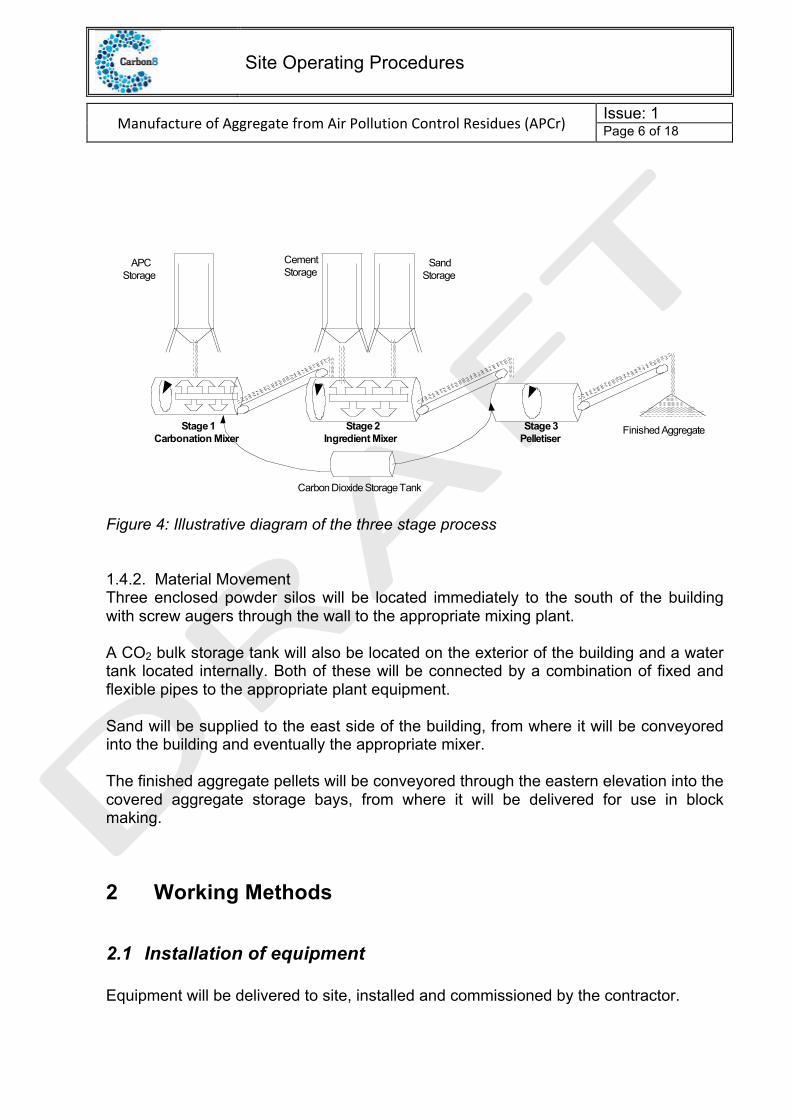
1.4 Process Illustration & Materials Movement 1.4.1 Process A plant will be constructed to consisting of a three stage process on a single production line. The three stages (Figure 3) of the process comprise:
• Stage 1: carbonation treatment of the APCr • Stage 2: blending with reagents • Stage 3: pelletising / curing.
Site Operating Procedures
ManufactureofAggregatefromAirPollutionControlResidues(APCr)Issue: 1 Page 6 of 18
Figure 4: Illustrative diagram of the three stage process 1.4.2. Material Movement Three enclosed powder silos will be located immediately to the south of the building with screw augers through the wall to the appropriate mixing plant. A CO2 bulk storage tank will also be located on the exterior of the building and a water tank located internally. Both of these will be connected by a combination of fixed and flexible pipes to the appropriate plant equipment. Sand will be supplied to the east side of the building, from where it will be conveyored into the building and eventually the appropriate mixer. The finished aggregate pellets will be conveyored through the eastern elevation into the covered aggregate storage bays, from where it will be delivered for use in block making.
2 Working Methods
2.1 Installation of equipment Equipment will be delivered to site, installed and commissioned by the contractor.
APC
Storage
Cement
StorageSand
Storage
Stage 2
Ingredient Mixer
Stage 3
PelletiserFinished Aggregate
Carbon Dioxide Storage Tank
Stage 1
Carbonation Mixer

Site Operating Procedures
ManufactureofAggregatefromAirPollutionControlResidues(APCr)Issue: 1 Page 7 of 18
2.2 Deliveries of materials to site
APCr and cements are fine powders, which will be delivered to site in standard powder tankers operated by third party operators (with appropriate licences, insurances etc.). The powders will be pumped into one of the silos located outside the southern wall of the building, which will be clearly identified and fitted with dust filters. Sand will be delivered by tipper lorry and/or loading shovel, where it will be placed in an initial receiving hopper for conveyoring into the process building. Carbon dioxide will be delivered by liquid tanker and pumped into a bulk storage tank. The tank and associated fittings will be installed and maintained under the direction of the CO2 supplier. A Carbon8 responsible person, trained for the task, will check all material deliveries. This will include checking the relevant paperwork, the connections to the correct receiving vessels and acting as a reversing banksman if required. All paperwork for delivered materials will be recorded in a site file.
2.3 Traffic Management The whole Lignacite site is subject to continuous traffic in the form of deliveries of sand and cement, dispatch of products, and forklift movements. On figures 1 and 2, the main traffic flow is indicated. A one-way system operates on the site. The site is entered and exited via the main entrance. The route around the site encircles the finished concrete block storage areas, as well as the main production and block finishing buildings. Various routes in certain areas are designated and appropriate for the actual deliver and collection points of a variety of materials and goods. The Carbon8 facility will operate as a sub-set of the main Lignacite facility and all Carbon8 vehicle management will be compatible and agreed by Lignacite. . Additionally, vehicles for the Carbon8 Aggregates plant may utilise the second gate adjacent to the railway. Again the actual traffic flow and use of this gate will be incorporated into the Lignacite general site plan. Carbon8 personnel will use the site car park for parking their personal vehicles. During deliveries, all non-essential personnel will vacate the immediate delivery area. If required, one member of Carbon8 staff may assist the delivery driver by acting as a banksman.

Site Operating Procedures
ManufactureofAggregatefromAirPollutionControlResidues(APCr)Issue: 1 Page 8 of 18
2.4 Operation of production plant 2.4.1 Silos Three sealed powder silos will be placed on site: two for storing the APCr, and another for storing cement. To the base of each silo, screw conveyor arms will be fitted. The conveyor from the APCR silo will feed into the stage 1 mixer. The conveyor from the cement silo will feed into the stage 2 mixer. The silos will be mounted on a level solid concrete slab constructed outside the process building. 2.4.2 Conveyors To prevent dust and wind-blown risk, sealed screw auger conveyors will be used where fine powders need to be transported. Belt conveyors will be used for the moist and bulk materials. 2.4.3 Mixers Three mixers are used in series to physically and chemically process the materials, changing their characteristics and properties, converting from fine powders into hard rounded pellets, suitable as a replacement aggregate in concrete blocks. 2.4.4 Carbon dioxide Pure carbon dioxide is added to the process, delivered from a bulk storage tank as either liquid or vapour as appropriate for the stage of the process. 2.4.5 Handling and Storage of product The pelletised product from the stage 3 mixer will be transported via an adjustable conveyor into the covered, storage bays to the eastern end of the building; with approximately one day’s production in each bay. Following quality control procedures, the majority of the finished aggregate will be moved, by mechanical shovel, from each bay in sequence and transported across the site for processing into concrete blocks. Some aggregates may also be loaded onto trucks and transported to other block making plants. 2.4.6 Cleaning and maintenance Regular cleaning will be necessary to maintain performance of the machines, which will generally be done at the end of each day. Cleaning of the mixers will involve opening the inspection hatches and loosening any material caked onto the mixer wall and blades. Material may also adhere to conveyor belts, which would be removed by regular scraping and hosing down. All loosened materials can be re-introduced into the process and is not discarded. All washing water will be collected in a sump and reused in the process.

Site Operating Procedures
ManufactureofAggregatefromAirPollutionControlResidues(APCr)Issue: 1 Page 9 of 18
3 Materials
3.1 Reagents The process involves blending the wastes with different reagents, including: a) Binder such as Portland cement (COSHH in appendix) b) Filler such as sand (COSHH in appendix) c) Water d) Carbon dioxide (COSHH in appendix)
3.2 Wastes The wastes that could potentially be processed through the plant are listed in table 1. Table 1. Wastes materials
EWC codes Waste type 01.04.09 Waste sand and clays 10.01.02 Coal fly ash 10.01.03 Fly ash from peat and untreated wood 10.01.16* 10.01.17
Fly ash from co-incineration
10.01.18* 10.01.19
Wastes from gas cleaning
10.01.24 Sands from fluidised beds 10.02.01 Wastes from processing slag 10.02.02 Unprocessed slag 10.02.07*
10.02.08 Solid wastes from gas treatment
10.03.19* 10.03.20
Flue gas dust
10.03.21* 10.03.22
Other particulates and dust (including ball-mill dust)
10.03.23* 10.03.24
Solid wastes from gas treatment
10.13.04 Wastes from calcination and hydration of lime 10.13.12* 10.13.13
Solid wastes from gas treatment
17.05.03* 17.05.04
Soil and stones
17.05.06 Dredging spoil 19.01.05* Filter cake from gas treatment 19.01.07 Solid wastes from gas treatment (APCr1) 19.01.11* 19.01.12
Bottom ash and slag
19.01.13* 19.01.14
Fly ash
19.01.15* 19.01.16
Boiler dust
19.01.19 Sands from fluidised beds

Site Operating Procedures
ManufactureofAggregatefromAirPollutionControlResidues(APCr)Issue: 1 Page 10 of 18
19.04.02* Fly ash and other flue-gas treatment wastes 19.08.05 Sludges from treatment of urban waste water 19.08.08* Membrane system waste containing heavy metals 19.08.14 Sludges from other treatment of industrial waste water 19.13.02 Solid wastes from soil remediation 19.13.04 Sludges from soil remediation
3.3 Quality control of aggregate Wastes will be accepted at the site in accordance with the Sector Guidance Note S5.06 and subject to a program of testing to ensure that the process parameters are appropriate for the particular source. The final product will be tested to ensure that the aggregate meets the Carbon8 Aggregate standard. In the unlikely event of the discovery of substandard aggregate, the product can be recycled through the process. The main stages and control mechanisms are illustrated in Figure 6 below.

Site Operating Procedures
ManufactureofAggregatefromAirPollutionControlResidues(APCr)Issue: 1 Page 11 of 18
Main Stages and Control Mechanisms of the
Carbon8 Aggregates Quality Process
1) APCr inputAPCr Pre -acceptance and acceptance compliant withSector Guidance Note S5.06
2) Recovery ProcessThree Stage process of Carbonation, Mixing andPelletising with individual recipes per EfW plant sourceand in accordance with permit conditions.
3) Sample and TestTest Manufactured Aggregates meet the Carbon8Aggregate Approved Standard, (agreed suitable for usein the manufacture Concrete Blocks to BS EN 771-3)
4) Carbon8 Aggregate Compliant ProductReady for Despatch to known and contracted customers
5) Produce Supply Documentation
6) TransportIn accordance with good practice to designated ConcreteBlock Manufacturers to be used in factory controlledprocesses for the production of blocks,
Records M
anagement & Audit Trails
Reject
Reject
Pass
Start
Fail
Point at whichAPCr ceases to
be a waste
4 Site Management
4.1 Working Hours The site will be operated within the current planning approval (currently 06:00 -22.00 Monday to Friday and 06:00 to 20:00 Saturday)
4.2 Personnel The site will normally require a minimum of two trained persons on site at all times. Lone working will not be permitted, without suitable arrangements in place, utilising support from the rest of the Lignacite workforce on site.
Site Operating Procedures
ManufactureofAggregatefromAirPollutionControlResidues(APCr)Issue: 1 Page 12 of 18
Following commissioning and at the commencement of production, an organisational chart will be displayed on the Carbon8 notice board, indicating management structure, emergency contact numbers, and individual responsibilities such as first aider, fire warden etc.
General support from Lignacite’s personnel may also be provided, such as workshop staff for minor fabrication, and a forklift driver.
4.3 Site Diary A site diary will be maintained throughout the operation of the plant. This will be used to record personnel on site and log deliveries of materials, daily activities including volumes of material processed, maintenance undertaken, any accidents or near misses, environmental monitoring etc.
5 Health, Safety and Welfare The Carbon8 facility will operate as a sub-set of the main Lignacite facility and all Health, Safety and Welfare requirements will be compatible and agreed by Lignacite.
5.1 PPE During the operation of the site the following PPE is mandatory as per Lignacite current assessments for all workers and visitors to the site: • stout footwear • high visibility vests or jackets In addition to the above, the following is mandatory for all workers on site: • boots with steel toe caps • overalls • hard hats • gloves Certain tasks will be further risk assessed and additional PPE will be specified and incorporated within the specific task related training. For these duties additional PPE may be required including (but not limited to) :
• heavy duty gloves • eye protection, from glasses to goggles • dust masks, rated up to FFP3 for fine dusts and vapours • ear protection • personal alarms for Carbon Dioxide

Site Operating Procedures
ManufactureofAggregatefromAirPollutionControlResidues(APCr)Issue: 1 Page 13 of 18
5.2 Training The personnel using the plant will be trained in its operation, with appropriate refresher training. Personnel must be familiar with the risk assessment and COSHH forms. Untrained personnel are not permitted to operate the machinery.
5.3 Accidents/Near Misses Any incidents and near misses will be reported to the project manager and a record of them logged in the site diary. Amendments will be made as necessary to the risk assessment, and appropriate changes to working practices to reduce the likelihood of repeat occurrences.
5.4 Site Conduct A no smoking, drugs and alcohol policy will be enforced at the site. Heavily contaminated PPE should not be worn in the welfare facilities, to prevent soiling of clean areas. Samples of waste materials and products will be stored in a designated area.
5.5 Site Facilities Welfare facilities will be made available and shared with Lignacite. Facilities comprise toilets, hot running water, kettle, and first aid kit, fire blanket and fire fighting equipment. An additional fire extinguisher, fire blanket and first aid kit will be installed in the plant area.
6 Environmental and Ecological issues
6.1 Mitigation of Environmental Risks 6.1.1 Release of Dust to Atmosphere Powders will be stored in sealed powder silos, with fitted filters to prevent exposure to the atmosphere of dust during filling. Screw conveyors are to be used to transport material from the silos into the mixing units. Rubber gaskets will be used to create an airtight seal with the silo, and a neoprene rubber sock secured with jubilee clips between the conveyor discharge and the filling nozzle on the mixers.

Site Operating Procedures
ManufactureofAggregatefromAirPollutionControlResidues(APCr)Issue: 1 Page 14 of 18
After passing through the first stage carbonation process, the APCr is wetted and treated, posing less of an airborne hazard. 6.1.2 Release of Water from the Treatment Process Water is used at several stages of the treatment process. However, it will only be introduced into the sealed mixing units via metering systems to ensure the required quantity is used. Therefore, there will be no ‘free water’ generated by the process as it will be bound with the solid materials. Hence, it is not likely that the treatment process will give rise to point source emissions to surface water. Washing water and any water spilt will drain to a sump from where it will be recycled into the process 6.1.3 Runoff Generated by Precipitation A small amount of rainfall will possibly hit the aggregate stored in covered bays, but the bays have a concrete floor and runoff will be collected and absorbed by the aggregate. 6.1.4 Noise The site is located on an existing industrial site. The working plant will occupy a fully enclosed building as shown in Figure 2. The site will only be operated during the operating hours permitted by the planning permission, and below those of the existing and detailed noise consent levels for the site. 6.1.5 Release of Carbon Dioxide Carbon dioxide is supplied to the site in liquid form. It is released into the process in a controlled form and fully incorporated chemically into the reactive materials of the treatment process, thus none should be released to atmosphere through the aggregate manufacturing process. The plant will be operated in a well-ventilated area and continuously monitored. In the event of a release, the supply will be isolated, and the problem rectified before proceeding with the process. 6.1.6 Disposal of Processing Wastes and Sub-Standard Product Operation of the plant will be associated with small unavoidable amount of spillage from some equipment such as the underside of conveyor belts. Wherever possible, engineered collection and control equipment will be incorporated into the design. All spillages will be swept up regularly and all spilt material and any sub standard product will be recycled through the treatment process. Other wastes generated (principally gloves, masks and office paper waste) will be recycled where reasonable facilities exist, or disposed of thorough an appropriate waste company.

Site Operating Procedures
ManufactureofAggregatefromAirPollutionControlResidues(APCr)Issue: 1 Page 15 of 18
6.2 Monitoring 6.2.1 Carbon Dioxide The building has an opening doors and roof ventilation. Additionally ‘forced air’ fans will be installed as required to provide adequate ventilation and prevent accumulation of carbon dioxide. Carbon dioxide alarms will be placed in the plant area to continuously monitor the gas emissions. The safe limits for air emissions are indicated in Table 3. The alarm will be set to trigger at 5,000ppm. Records of the background carbon dioxide levels will be made at the start of each working day, and on at least one occasion daily during operation of the plant. Any incidences of the alarm triggering will be recorded in the site diary. Table 3: Safe limits for CO2 levels in air
Determinant Trigger level
CO2 10,000 ppm (over 8 hours period)
30,000 ppm (over 15 minutes period)
6.2.2 Dust The storage, conveying, and mixing equipment used for the powders will be sealed, therefore dust will be minimal. Dust in the air will be monitored visually during the treatment and recorded in the site diary. Should any dust be observed, modifications will be made to the equipment to reduce this as much as practically possible. Regular checks will be carried out to ensure the materials are kept safe and no spillages occur. If a problem occurs then this will be recorded in the site diary. 6.2.3 Water The personnel on site will constantly monitor the plant and the weather conditions. Records will be kept in the site diary. 6.2.4 Noise As part of the commissioning of the plant, noise readings within the building will be taken and recorded and included within the appropriate risk assessment.
6.3 Emergency Responses Emergency procedures operating on the site will be detailed in an emergency plan held in the site office. The procedures will build upon and be compatible with those of the Lignacite block works. The emergency plan takes into account sources of ignition, fuel and oxygen immediately beyond the area of the Carbon8 Aggregates operation.

Site Operating Procedures
ManufactureofAggregatefromAirPollutionControlResidues(APCr)Issue: 1 Page 16 of 18
In the unlikely event of an uncontrolled release, the following procedures will be followed. 6.3.1 Release of dust Dust release may occur as a result of a failed seal or blockage in a conveyor. In the event of a dust release, the offending conveyor or mixer will be immediately stopped. Spilled material will be dampened with water and swept/shovelled into spill bins, prior to recycling back into the process. 6.3.2 Release of water Release of water may occur from the plant itself or precipitation onto the site. In the case of the former, the supply will be shut off, and dry sand will be brought in from the nearby stockpile to absorb the water and prevent runoff. In the case of the latter, run off is collected into surface water drains with sediment catchment, these will be checked regularly for level of sediment to prevent material entering the main site drainage areas. The limited precipitation able to fall on the aggregate stockpile will run to the back of the covered bays where it will be absorbed by the stockpile. 6.3.3 Release of carbon dioxide In the event of an uncontrolled carbon dioxide release, the supply will be isolated, and the fault rectified before proceeding. 6.3.4 Fire-fighting water runoff In the unlikely event of a major fire, all vessels containing Air Pollution Control Residues will remain closed and the APCr will not mix with the fire-fighting run-off water. The water can therefore be allowed to run into the surface water drains.
7 Permitting The plant will be operated under an environmental permit issued by the Environment Agency. The storage of APC residues is limited by the capacity of the storage silos, thus no more than 160t of untreated waste will be on site at any one time.

Page 17 of 18
Thispageisintentionallyblank