draft - section c operating (folder 2). · 21 main boiler feed pump trip (manual reactor trip m all...
TRANSCRIPT

Appendix D Scenario Outline Form ES-D-1
2
Facility: Indian Point 2 Scenario No.: NRC#1 Op-Test No.: 1
XMT- RCS020A
Examiners : Operators:
5
6
7
Initial Conditions: 3% Rated Thermal Power, MOL
MAL- ATS007A
MAL- RCSO14B
MAL- EPS001
MOC- SIS001
Turnover: Unit 2 is at 3% power, recovering from a 7 day forced outage to repair body to bonnet leak on PRZR Spray Loop 23 Bypass Valve 524. Shift orders are to continue the startup in accordance with Pop 1.3 Plant Startup, Mode 2 to Mode 1. The previous shift completed POP 1.3 though step 4.23. Operations Manager has directed you to baseload the HP Steam Dumps to approximately 8% prior to placing the unit on line per POP-2.1. The Operations Manager, Reactor Engineering and Power Marketing have authorized a rate of power increase of 200 MWe per hour to 100% RTP.
RCSO14B
RCP007C
* (N)ormal (R)eac
Event Type*
N SRO/BOP
R RO
Event Description
Raise reactor power
I ALL
Pressurizer Level Channel 2 (LT-460) Fails Low (TS SRO)
C ALL
22 SG Tube Leak (5 gpm) (TS SRO)
C SRO/BOP
23 RCP High Vibration
21 Main Boiler Feed Pump Trip (Manual reactor trip
M ALL
SGTR
with subsequent
I ~ o s s of Offsite Power
21 SI Pump Fails to Auto Start r- I
ity, (I)nstrument, (C)omponent, (M)ajor
NUREG-1021, Draft Revision 9 1 of 19

Simulator Setup
Reset to IC-124 Validation time = 105 minutes.
Execute batch file Bat "NRC#l .bat" from Ph.D Expert window:
A MOC-SIS001 SI1 SAFETY INJECTION PUMP 21 MOTOR IMF MOC-SISOO1 (-1 0) 4
XMT-RCS020A FIXED OUTPUT: LT-460 PZR LEVEL CH.2 IMF XMT-RCS020A (1 0) 0.000000 0 40.412601 A MAL-RCS014B STEAM GENERATOR 22 TUBE LEAK (NR) IMF MAL-RCS014B (2 0) 0.050000 0 0.000000 A MAL-RCP007C IMF MAL-RCP007C (3 0) 10.000000 7200 4.000000 A MAL-ATS007A MBFP 21 THRUST BEARING FAILURE (NR) IMF MAL-ATS007A (4 0) TRUE
RCP 23 HIGH VIBRATION
A Loss of Offsite Power when manual SI pushed TRGSET 29 "xaoi610a.eq.l"
A SGTR 22 SG gets big when reactor trips TRGSET 30 "JBKRTA.EQ.0"
TRG 29 "IMF MAL-EPS001 (-1 0) TRUE"
TRG 30 "IMF MAL-RCS014B (-1 0) 5.00000 0 0.050000"
Verifv that the following commands amear in the Instructor Station Summarv: -1111 X I $ , I .
?? Desapboo Delay Romp Event Value Fnal InserlTime
030000 O O C O O O hone n:a 3u-c 5 ooonoo 0 000000 -RCSOZoH FlrED OUTPU LT-460 PZ 000000 000000 1 47 6603
RCSOl4B STEAM GENERATOR 22 TUBE LEAK 000000 000000 2 0 0 0 5 OD0000 0 1 0 ~ 1 ~ l 0 0 0 0
ATS007A MBFP 21 THRUST BEARING FAILUF? 000000 000000 4 FALSE FALSE 00 0000 RCW0iC RCP22 H1i;HVlBRATION o o o o o o 020000 3
I
2of19

Simulator SetuD
Verify that Conditional Trigger 29 & 30 appears on Event Trigger 29 and 30 as follows:
""I f a , , k j , ,
Event# Event Action
130 JBKRTA.EQ.0 TI1 I
, .. - . : - l o l x l :i:
Event# Event Action
I
1-1 Finish 1 # Action 1 6 Available 17 Available 1 8 Available 19 Available 20 Available 21 Available 22 Available 23 Available 24 Available 25 Available 26 Available 27 Available 28 Available
1
TRUE
FALSE
3of 19

Appendix D Required Operator Actions Form ES-D-2
Prior to start of scenario, brief team on power escalation orders. Allow them to formulate a reactivity plan and do their brief outside the simulator. Provide them required graphs and NUPOP, and turnover sheet.
Op-Test No.: 1 Scenario No.: 1 Event No.: 1
Event Description: Raise Reactor Power from 3% reactor power
Page 1 of 1
Time Position
SRO
RO
SRO
BOP
SRO
Directs activities associated with power increase per 2-POP-1.3, “Plant Startup, Mode 2 to Mode 1”:
- Rod Motion
- Dilution
Adds Positive reactivity
- Rod Motion
- Dilution
Directs activities associated with shifting Feedwater from Auxiliary Feedwater Pumps to Main Feedwater Pumps
Shifts Feedwater from Auxiliary Feedwater Pumps to Main Feedwater Pumps per 2-SOP-21.1 “Main Feedwater System.”
- Checks operation of main feed and bypass feed flow control valves
Shifts Feedwater control from AFW pumps to Main Feedwater System
Control SG levels on main Feedwater bypass flow control valves
Align AFW pumps and flow control valves for automatic operation per 2-SOP-21.3 “Auxiliary Feedwater Operation”
-
-
-
Initiates Turbine Generator startup operations per 2-SOP-26.4, “Turbine Generator Startup, Synchronizing, Voltage Control and Shutdown”
SI MU LATO R 0 P ERATO R: Activate trigger 1 to start the next event Pressurizer Level Channel 2 (LT-460) Fails Low (TS SRO) when directed by the Lead Evaluator.
4o f19 NUREG-1021, Draft Revision 9

Appendix D Required Operator Actions Form ES-D-2
Op-Test No.: 1 Scenario No.: 1 Event No.: 2 Page1 o f3
Event Description: Pressurizer Level Channel 2 (LT-460) Fails Low
Time - Position
RO
BOP
SRO
RO
SRO
BOP
SRO
RO
Applicant’s Actions or Behavior
Diagnose Pressurizer Level Channel 2 failed low P -
Refers to Alarm response Procedure -
- - -
SAF 3-3 Pressurizer Low Level 18% 5% SAF 4-3 Pressurizer Lo Lo Level Channel Trip 5% SGF 2-9 RCS Reduced Inventory SFF 1-7 PRZR Heater Group Tripped
Directs RO to perform immediate operator actions (from memory) of 2-AOP-INST-1, “Instrument/Controller Malfunctions”
Places 22 Charging Pump speed controller in manual and adjusts charging flow as necessary to maintain Pressurizer Level on program (per Graph RCS-2, “Pressurizer Level vs. Tave”)
Directs actions to select operable channels for control and alarm
Defeats controlling PRZR Level Channel by placing U460A (Pressurizer Level Defeat Transfer Switch) in DEFEAT CH2 (located in Foxboro rack B-6)
Directs initiation of actions to restore letdown using SOP-3.1, “Charging Seal Water and Letdown Control”
Restores letdown: -
- Verifies a charging pump is in service
Verifies HCV-142, Charging Line Flow Controller is throttled open
Verifies Charging flow established with 204A 22 Hot Leg Alternate Charging Stop is OPEN
Verifies letdown orifice stops CLOSED (200 A, B, C)
Verifies that switch Letdown Flow Control Valves ABC in REMOTE
Verifies Letdown Line Isolation Stops 200A and 2008 are OPEN
-
-
-
-
50f 19 NUREG-1021, Draft Revision 9
Appendix D Required Operator Actions Form ES-D-2
Event Description: Pressurizer Level Channel 2 (LT-460) Fails Low
Position
RO
SRO
RO
SRO
RO
SRO
Amlieant’s Actions or Behavior
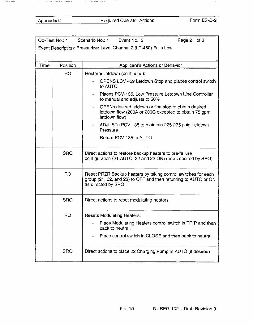
Restores letdown (continued): - OPENS LCV 459 Letdown Stop and places control switch
to AUTO
Places PCV-135, Low Pressure Letdown Line Controller to manual and adjusts to 50%
OPENS desired letdown orifice stop to obtain desired letdown flow (200A or 200C excepted to obtain 75 gpm letdown flow)
ADJUSTS PCV-135 to maintain 225-275 psig Letdown Pressure
-
-
-
- Return PCV-135 to AUTO
Direct actions to restore backup heaters to pre-failure configuration (21 AUTO, 22 and 23 ON) (or as desired by SRO)
Reset PRZR Backup heaters by taking control switches for each group (21, 22, and 23) to OFF and then returning to AUTO or ON as directed by SRO
Direct actions to reset modulating heaters
Resets Modulating Heaters: - Place Modulating Heaters control switch in TRIP and then
back to neutral.
Place control switch in CLOSE and then back to neutral -
Direct actions to place 22 Charging Pump in AUTO (if desired)
6o f19 NUREG-1021, Draft Revision 9

Appendix D Required Operator Actions Form ES-D-2
Page3 o f 3 Op-Test No.: 1 Scenario No.: 1 Event No.: 2
Event Description: Pressurizer Level Channel 2 (LT-460) Fails Low
Time - Position
RO -
SRO
SRO
BOP
Places 22 Charging Pump to AUTO: -
-
-
-
-
-
Place speed control to MAN-BAL
Adjust bias knob until deviation meter indicates zero
Place speed controller to AUTO
Slowly return bias knob to zero
Verify RCP Seal Injection Flow 6-1 2 GPM
Monitor automatic Przr level control per Graph RCS-2, “Pressurizer Level vs Tave”
Refer to Technical Specification 3.3 “Instrumentation” and Table 3.3.1 -1 “Reactor Protection System Instrumentation” for required actions:
-
- Determine that TS 3.3.1 Condition A applies
Determine from table 3.3.1 -1 function 8 directs that Condition K applies
Determine form TS 3.3.1 Condition K that the bistable must be placed in trip within 72
-
Direct actions to trip bistable LC-460A (LOOP 2) Hi Level Trip in the White Foxboro Rack A-12
CUE: IF the SM is asked if Bistables should be tripped, direct the team to trip the appropriate bistables.
Place bistable LC-460A (LOOP 2) Hi Level Trip in the White Foxboro Rack A-12 to TRIP
SI MU LATOR OPERATOR: Activate Trigger 2 to start the next event (22 SG Tube Leak) when directed by the lead evaluator. (Wait until PRZR level is stable from previous event, else team will have to wait in AOP-SG-1 to determine leak rate)
7o f19 NUREG-1021, Draft Revision 9

Required Operator Actions Form ES-D-2 Appendix D
3p-Test No.: 1 Scenario No.: 1 Event No.: 3 Page 1 of 3
Event Description: 22 SG Tube Leak (5 GPM)
Time - Position
BOP
TEAM
SRO
SRO/RO
SRO
TEAM
RO/BOP
Applicant’s Actions or Behavior
Acknowledge alarms and perform ARPs - SA-1 (3-7) R49 Steam Generator Blowdown Hi
RadRrouble (WARN SETPOINT(after about 1 minute))
SA-1 (3-9) R-45 Air Ejector Radiogas Hi RadRrouble (after about 6 minutes)
-
Diagnose steam generator tube leak
Enter 2-AOP-SG-1, “Steam Generator Tube Leak”
Verify that Pressurizer level is being maintained by charging flow:
Checks PRZR level able to be maintained with two charging pumps
Checks PRZR level > 11%
Checks RCS Pressure and Subcooling
-
-
-
Directs RO to evaluate plant conditions for indication of Gross TubeLeakage
EVALUATOR NOTE: The team will not have clear indication of Gross Tube Leakage at this point.
Initiate determination of affected SG. Checks:
- N-16 Monitor
- Steam Line surveys
- Chemistry results
BOOTH OPERATOWCOMMUNICATOR: When chemistry or the NPO are contacted, report back that 22 SG is affected.
Check R-45 operable
8o f19 NUREG-1021, Draft Revision 9

_______~
Appendix D Required Operator Actions Form ES-D-2
Op-Test No.: 1 Scenario No.: 1 Event No.: 3 Page2 of 3
Event Description: 22 SG Tube Leak (5 GPM)
~
Time Position
BOP
BOP
SRO
SRO
BOP
TEAM
SRO
SRO
Initiate attachment 1, “R-45 Estimated Leak Rate”
NOTE: If chemistry is requested, provide the following information:
-
-
Condenser air in leakage = 6 SCFM
RCS total gaseous activity = 2.5 e-3 uCi/cc
Calculates leak rate of approximately 5 gpm
Directs Chemistry to perform Primary to Secondary Leak Rate determination
BOOTH OPERATOWCOMMUNICATOR: After about 10 minutes, report that Pri to Sec leakrate is 4.3 GPM
Notify Health Physics of SGTL ~~
Initiate Attachment 2, SG Leak Rate Data Sheet
Determine primary to secondary leak rate using
- N-16
- Chemistry grab sample results
- Attachment 1
id EVALUATOR NOTE: N-16 data is not vz )elow 30% power. Team should use Chemistry results and Attachment 1 calculation to determine that leak rate is 3-5 gpm
Determine that leak rate is >lo0 gpd
Direct chemistry to draw backup samples and re-perform Primary to Secondary Leak Rate calculation.
BOOTH OPERATOWCOMMUNICATOR: When Chemistry is contacted, report that additional samples have been obtained and that the leak rate has been verified at 4.3 gpm
9of 19 NUREG-1021, Draft Revision 9

Appendix D Required Operator Actions Form ES-D-2
Op-Test No.: 1 Scenario No.: 1 Event No.: 3
Event Description: 22 SG Tube Leak (5 GPM)
Page3 of 3
Time Position t SRO
SRO
- Applicant’s Actions or Behavior
Initiate notifications per SAO-124, Oral Reporting of Non- Emergency Events and Items of Interest and Significant Occurrence Reporting
P -
Direct Chemistry to calculate leak rate every 2 hours while shutting down
Evaluate attachment 3 and Technical Specification 3.4.1 3 to determine Shutdown Requirements:
TS 3.4.1 3 Condition A - reduce leak rate to allowable in 4 hours (cannot be met)
Be in mode 3 in additional 6 hours
Be in mode 5 in additional 36 hours
-
-
-
Initiate plant shutdown IAW POP-3.1, “Plant Shutdown Mode 1 to Mode 3.”
SI MU LATO R 0 PERATOR: Activate Trigger 3 when directed by the Lead Evaluator to proceed to the next event (23 RCP High Vibration)
10 of 19 NUREG-1021, Draft Revision 9

Appendix D Required Operator Actions Form ES-D-2
Op-Test No.: 1 Scenario No.: 1 Event No.: 4 Page 1 of 1
Event Description: 23 RCP High Vibration
Time P
Position
BOP
SRO
TEAM
BOP
SRO
BOP
BOP
BOP
SRO
-
x_I
Applicant’s Actions or Behavior ___I
Acknowledge alarm and perform ARP: - SF 4-6 23 RCP HI Vibration
Enter 2-AOP-RCP-1, Reactor Coolant Pump Malfunction
Determine immediate reactor trip and RCP trip NOT required: -
-
-
-
-
-
Checks Stator winding temp 2 250°F AND Tave 2 547°F
Stator winding temp 2 270°F AND Tave < 547°F.
RCS seal 1 AP < 200 psig.
Sustained RCP vibration > 20 mils
RCP motor bearing temp 2 200°F
#1 Seal inlet temp 2 225°F
Initiate data collection per Attachment 1, RCP Data Sheet
Notify Plant Engineering
Check vibration e1 3 mils (no)
Check vibration spiking (no)
Check vibration trend increasing < 1 mil/hr (no)
Note: Vibration trend is increasing at a rate of 3 mils/hr
Continue plant shutdown per POP-3.1
SI MU LATOR OPERATOR: Activate trigger 4 when directed by Lead Evaluator to proceed to the next event (21 MBFP trips)
11 of 19 NUREG-1021, Draft Revision 9

Appendix D Required Operator Actions Form ES-D-2
Op-Test No,: 1 Scenario No.: 1 Event No.: 5
Event Description: 21 Main Boiler Feed Pump Trips
Page 1 of 1
Time - Position
RO -
SRO
RO
SRO
Applicant’s Actions or Behavior - P
Diagnose trip of 21 Main Boiler Feed Pump
Diagnose Loss of Feedwater: - Direct RO to perform immediate operator actions of 2-
AOP-FW-1 Loss of Main Feedwater
Performed from memory: -
-
- Manually trip the reactor
Checks any Main Boiler Feed Pump operating (no)
Checks Reactor power greater than 4% (yes)
Directs team to perform immediate operator actions of EOP E-0, Reactor Trip or Safety Injection
NOTE: 1. The SGTL will increase in size to a SG Tube Rupture (600 gpm) when the
reactor is tripped (from conditional trigger 30 which actuates from condition of reactor trip breakers open)
2. A loss of offsite power will occur when SI is manually actuated (from conditional trigger 29 which actuates from condition of manual SI buttons pushed)
12 of 19 NUREG-1021, Draft Revision 9
Appendix D Required Operator Actions Form ES-D-2
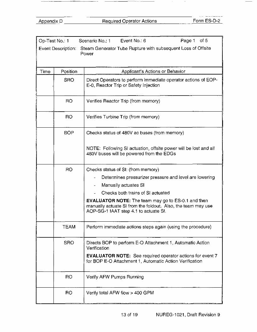
Op-Test No.: 1 Scenario No.: 1 Event No.: 6 Page 1 of 5
Event Description: Steam Generator Tube Rupture with subsequent Loss of Offsite Power
Time P
Position
SRO
RO
RO
BOP
RO
TEAM
SRO
RO
RO
Amlicant’s Actions or Behavior
Direct Operators to perform immediate operator actions of EOP- E-0, Reactor Trip or Safety Injection
Verifies Reactor Trip (from memory)
Verifies Turbine Trip (from memory)
~~
Checks status of 480V ac buses (from memory)
NOTE: Following SI actuation, offsite power will be lost and all 480V buses will be powered from the EDGs
Checks status of SI: (from memory) -
- Manually actuates SI -
Determines pressurizer pressure and level are lowering
Checks both trains of SI actuated
EVALUATOR NOTE: The team may go to ES-0.1 and then manually actuate SI from the foldout. Also, the team may use AOP-SG-1 IAAT step 4.1 to actuate SI.
Perform immediate actions steps again (using the procedure)
Directs BOP to perform E - 0 Attachment 1, Automatic Action Verification
EVALUATOR NOTE: See required operator actions for event 7 for BOP E-0 Attachment 1, Automatic Action Verification
Verify AFW Pumps Running
Verify total AFW flow > 400 GPM
- - P
13 of 19 NUREG-1021 Draft Revision 9

Appendix D Required Operator Actions Form ES-D-2
Op-Test No.: 1 Scenario No.: 1 Event No.: 6 Page2 of 5
Event Description: Steam Generator Tube Rupture with subsequent Loss of Offsite Power
Time __j
Position
RO
RO
RO
RO
RO
RO
RO
SRO
~~
Amlicant’s Actions or Behavior
Verify SI System Flow -
- Checks RCS Pressure c 11 60 psig (no)
Places one RHR pump in pullout
Check RCP Seal Cooling - Dispatch an NPO to align backup cooling to the Charging
Pumps, RHR pumps, and SI pumps
Dispatch an NPO to locally close SWN-4 and SWN-5 in the zurn strainer pit
-
Check cold leg temperatures stable at or trending to 547°F
Check PRZR Porvs and Spray Valves Closed
Check RCPS stopped (yes- loss of offsite power)
Check if any SG is faulted (no)
Check if SG tubes are intact (no, 22 SG is Ruptured) -
-
-
-
Main Steam Line radiation recorder
Condenser air ejector radiation recorder
SG Blow down radiation recorder
No SG Level increasing in an uncontrolled manner
Transitions to EOP E-3, Steam Generator Tube Rupture
14of 19 NUREG-1021 , Draft Revision 9

Appendix D Required Operator Actions Form ES-D-2
Op-Test No.: 1 Scenario No.: 1 Event No.: 6
Event Description: Steam Generator Tube Rupture with subsequent Loss of Offsite
SRO Determine required core exit temperature:
NOTE: 51 0°F expected with 22 SG pressure > 1025 PSlG
15of 19 NUREG-1021, Draft Revision 9

Appendix D Required Operator Actions Form ES-D-2
Op-Test No.: 1 Scenario No.: 1 Event No.: 6 Page4 of 5
Event Description: Steam Generator Tube Rupture with subsequent Loss of Offsite Power
Time Position
BOP
RO
BOP
BOP
RO
RO
RO
RO
RO
TEAM
Applicant's Actions or Behavior
Check Intact SG Levels - Maintain total feed flow > 400 gpm until narrow range
level > lo% in at least one SG
Check PORVs and Block Valves
Reset SI and CI Phase A
Check RCS pressure greater than 320 PSlG and then stop RHR pumps and place in AUTO
Establish maximum charging flow
Check 22 SG pressure stable or increasing
Check RCS subcooling > value from table (>39"F expected)
Depressurize RCS using PORV
- Opens one PORV - Monitors RCS Pressure, 22 SG Pressure, PRZR Level,
and RCS subcooling
Closes PORV when RCS pressure < 22 SG Pressure, o PRZR Level > 71 %, or subcooling < value from table
-
Checks RCS pressure increasing
Checks if SI flow can be terminated -
-
-
- PRZR Level > 14%
Checks subcooling greater than value from table
AFW flow > 400 GPM
RCS Pressure stable or increasing
160f 19 NUREG-1021, Draft Revision 9

Appendix D Required Operator Actions Form ES-D-2
Page4 o f5 I I Op-Test No.: 1 Scenario No.: 1 Event No.: 6
Event Description: Steam Generator Tube Rupture with subsequent Loss of Offsite Power
TEAM Verify SI system flow not required -
- PRZR Level > 14%
Checks Subcooling greater than value from table
EVALUATOR NOTE: Terminate scenario after SI dumps stopped, or at the discretion ot the lead evaluator.
17of 19 NUREG-1021, Draft Revision 9

Appendix D Required Operator Actions Form ES-D-2
Op-Test No.: 1 Scenario No.: 1 Event No.: 7 Page 1 of 1
Event Description: 21 SI Pump Fails to Auto Start (E-0, Attachment 1 Automatic Action Verification)
Time I Position
BOP
1 BOP
I BOP
BOP I
I I BOP
I BOP
I BOP
I BOP
A p I
Verify charging system operation -
- Starts one charging pump in manual at maximum speed
Align charging system to the RWST (opens LCV-l12B, Closes LC-l12C, place Makeup Control Switch to STOP)
Check 345 KV MO Disc Switch F7-9 Open - verifes BKR 7 and 9 open
Check status of 480 V buses -
-
Determines all are powered from EDGs
Direct personnel to align lighting to TSC bus
Verify FW Isolation
Check if MSlVs should be isolated
Check SW system operation
Check Three SI Pumps running - Manually starts 21 SI pump
- OPEN851B
- Check RHR pumps running
Check SI system valve aligment
Verify Containment Fan Coolers in service
Verify AFW Flow to all SGs
NOTE: The team may use prudent operator action to isolate AFW flow to 22 SG when NR Level is > 10%
Verify Containment Ventilation Isolation
Verify Containment Isolation Phase A
Check if CS should be actuated ~~
Verify CCR Air Conditioner status
Notify SRO Attachment 1 complete
18 of 19 NUREG-1 021, Draft Revision 9

Shift Turnover
Watch Team Turnover Sheet:
Datemime:
RCS Temp:
RCS Press:
PZR Level:
RCS Total Leakage:
RCS Unidentified Leakage:
Xenon:
EFPD:
PZR Press Control:
PZR Level Control:
Service Water:
Risk Assessment:
TODAY
549 O F
2235 psig
38 %
0.1 gpm
0.1 gpm
Increasing
30
Channel 1
Channel 2
3 Header Ops
Green
Condition: Power Ops
% Power: 3%
MW Gross: 0
River Water: 63 O F
Boron Conc: 1530 ppm
Control Rods 105 CBD
Condenser Air leakage 6 SCFM
RCS Gas activity 2.5E-3 pCi/cc
Daily Risk Factor: 0.78
Plant Equipment Status :
No equipment out of service
Instructions to the Shift:
Continue plant startup IAW POP-1.3. Unit 2 is at 3% power, recovering from a 7 day forced outage to repair body to bonnet leak on PRZR Spray Loop 23 Bypass Valve 524. Shift orders are to continue the startup in accordance with Pop 1.3 Plant Startup, Mode 2 to Mode 1. The previous shift completed POP 1.3 though step 4.23.
Operations Manager has directed you to baseload the HP Steam Dumps to approximately 8% prior to placing the unit on line per POP-2.1
The Operations Manager, Reactor Engineering and Power Marketing have authorized a rate of power increase of 200 MWe per hour to 100% RTP.
Page 19 of 19

Appendix D Scenario Outline Form ES-D-1
Facility: Indian Point 2 Scenario No.: NRC#2 Op-Test No.: 1
Examiners: Operators:
Initial Conditions: 100% Rated Thermal Power, MOL. 21 EDG is out of Service. 22 Charging Pump is out of service.
Turnover: Unit 2 is at 100% Power steady state conditions 340 EFPD. 21 EDG is out of service and has been inoperable for 42 hours. Maintenance is currently performing repairs.
In addition, 22 Charging Pump was removed from service for corrective maintenance 18 hours ago. Expected return to service in 35 hours.
Event No. 1
2
3
4
5
Malf. No.
RLY- DSGOOS
MAL- EPS007D
MOT- CVC003A
MAL- EPS001
MAL- DSG003B
MOC- swso10
MOC- sws-011 -
' (N)ormal (R)eac:
Event ~ Type*
N BO P/S RO
R RO
C ALL
C ALL
M ALL
C SRO/BOP
Event Description
23 EDG inoperable due to 86 Lockout Relay tripped Begin TS required plant shutdown
Loss of Bus 6A (Lose 23 CHG Pump, Starts 21 CHG Pump)
21 Charging Pump Trips
Manual Reactor Trip
Loss of all AC Station Aux Xfmr fails
22 EDG fails to start
25 SW Pump Fails to auto start following start of 22 EDG and energizing associated 480V buses
(I)nstrument, (C)omponent, (M)ajor
1 of 13

Simulator Setup
1. Execute batch file Bat "NRC2.bat from Ph.D Expert window:
A LOA-DSG055 DSG-NT-89 DG-21 MANUAL-OFF-AUTO (ECS) IRF LOA-DSG055 (-1 0) OFF A LOA-DSG032 DSG-NT-110 BKR 52/EG1 RACK-OUT/RACK-IN IRF LOA-DSG032 (-1 0) OUT A LOA-EPSO10 52-C1 C 21 480V BKR RACK OUT/ RACK IN IRF LOA-EPS010 (-1 0) OUT A MOC-SWSO10 SW5-2A SW PUMP MOTOR 25 480V BUS 2A IMF MOC-SWS010 (-1 0) 4 A MOC-SWSOll SW5-3A IMF MOC-SWSO11 (-1 0) 4 A MAL-DSG003B IMF MAL-DSG003B (-1 0) TRUE A RLY-DSGOOS RELAY FAILURES: 86-DG23 DG23 LOCKOUT RELAY IMF RLY-DSGOO9 (1 0) 3 A MAL-EPSOO7D IMF MAL-EPS007D (2 0) TRUE A MOT-CVC003A C1 CHARGING PMP 21 MOTOR IMF MOT-CVC003A (3 0) 3
SW PUMP MOTOR 25 480V BUS NO. 3A
DG 22 AIR START FAILURE
480V BUS 6A FAULT
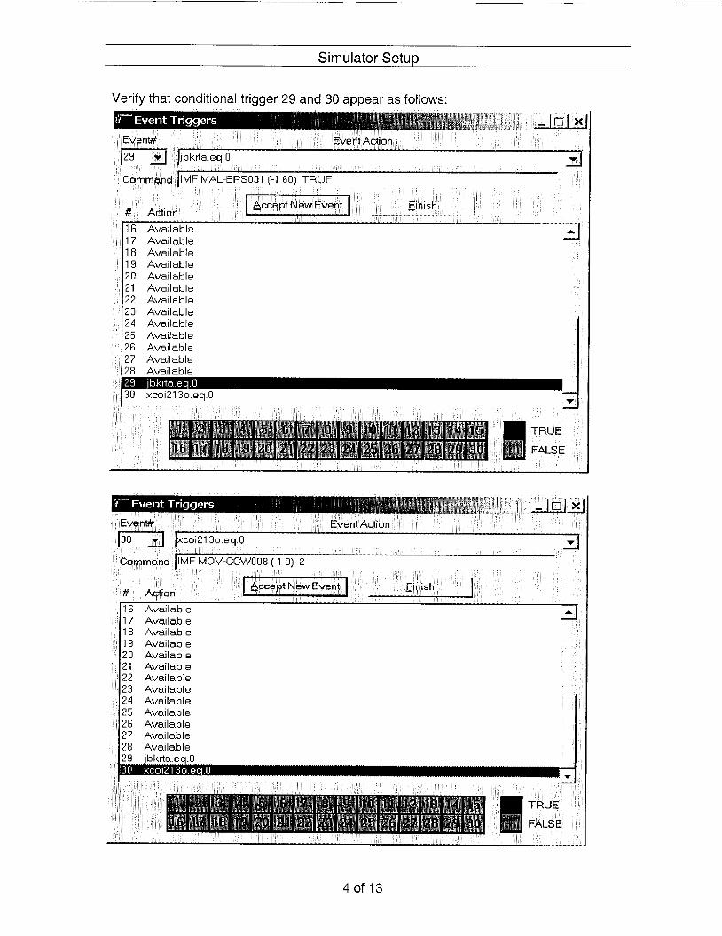
A MOV 625 fails closed after 204 closed TRGSET 30 "xcoi213o.eq.O"
A Loss of Statin Aux Transforem 60 seconds after RX Trip TRGSET 29 "jbkrta.eq.0"
TRG 30 "IMF MOV-CCW008 (-1 0) 2 'I
TRG 29 "IMF MAL-EPS001 (-1 60) TRUE"
2. 3. 4. 5.
Place CS for 21 EDG in Pullout Place 23 Charging pump in auto operation. Place CS for 22 Charging Pump in Pullout Verify that standard PlCs screens are displayed (no screens that could cue the team to upcoming events)
2of 13

Simulator Setup
Validation time 105 minutes
Verify the following commands appear in the instructor station summary:
GC-5WSU11 5% ?A SW W'dPMCTOR 25 46 110 IJII 00 00 00 0 0 INone nia Pllt CIS on 110 (10 000000 0 0 0 0 0 0 None FALSE FALSE o o o o o n
LY-DSG309 RELAY F4ILCIRES 85 DG?3 DG ooo3no nnnoon 1 n h i?natgi?e 000000 onndun oooooo i FALSE FALSE co uo no X-EPSUUiD 400'~ BUS 6A FAUL-
OT-CVCOC?A i l CI-WRGII'JG FMP21 MG nnnnoo oooooo 3 nia mding short 00 00 00
AL-DSGOEB DG ZZARSTAGTFALURE
Tuggers TRUE
FALSE
3of 13
Si m u lato r Setup
Verify that conditional trigger 29 and 30 appear as follows:
20 Available 21 Available 22 Available 23 Available 24 Available 25 Available 26 Available 27 Available
I J U xcoi213o.eq 0 71 I 2
TRUE
FALSE
19 Available 20 Available 21 Available 22 Available 23 Available 24 Available 25 Available 26 Available 27 Available 28 Available
T . I . ....... . ~
d
TRUE
FALSE
4of 13
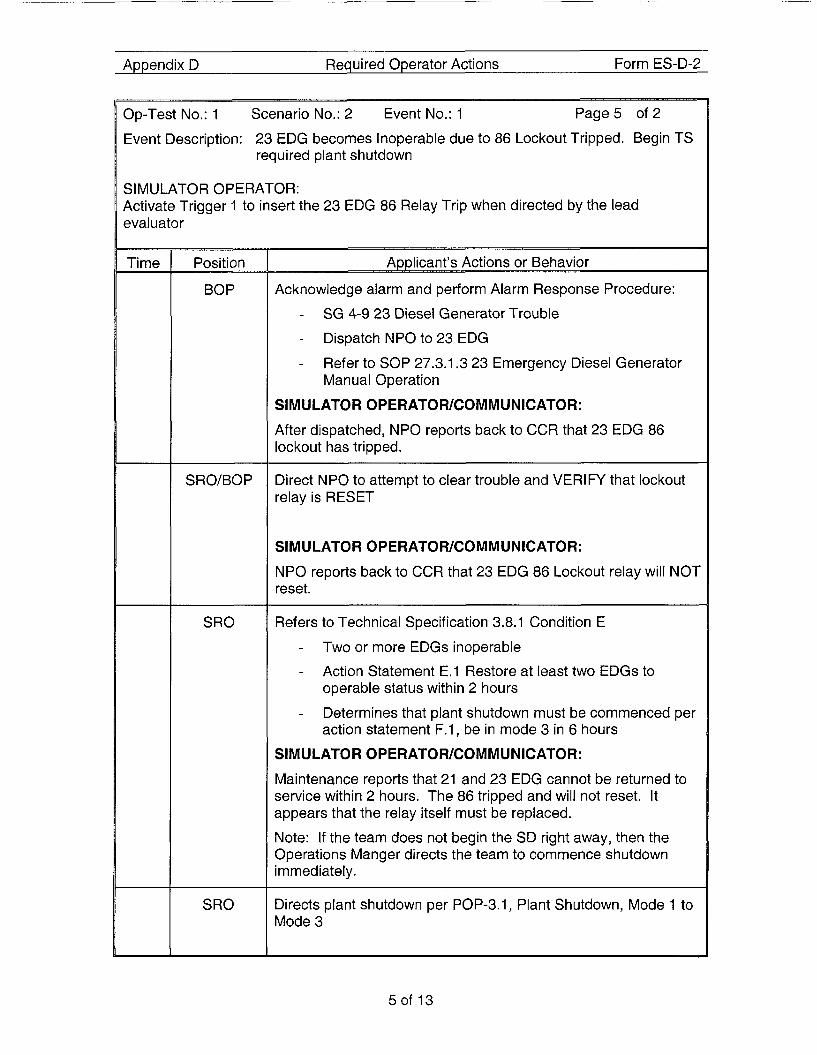
Appendix D Required Operator Actions Form ES-D-2
Op-Test No.: 1 Scenario No.: 2 Event No.: 1 Page5 of 2
Event Description: 23 EDG becomes Inoperable due to 86 Lockout Tripped. Begin TS required plant shutdown
SIMULATOR OPERATOR: Activate Trigger 1 to insert the 23 EDG 86 Relay Trip when directed by the lead evaluator
Time Position
BOP P
SRO/BOP
SRO
SRO
Acknowledge alarm and perform Alarm Response Procedure: -
-
-
SG 4-9 23 Diesel Generator Trouble
Dispatch NPO to 23 EDG
Refer to SOP 27.3.1.3 23 Emergency Diesel Generator Manual Operation
SIMULATOR OPERATOWCOMMUNICATOR:
After dispatched, NPO reports back to CCR that 23 EDG 86 lockout has tripped.
Direct NPO to attempt to clear trouble and VERIFY that lockout relay is RESET
SIMULATOR OPERATOWCOMMUNICATOR:
NPO reports back to CCR that 23 EDG 86 Lockout relay will NOT reset.
Refers to Technical Specification 3.8.1 Condition E -
-
Two or more EDGs inoperable
Action Statement E.l Restore at least two EDGs to operable status within 2 hours
Determines that plant shutdown must be commenced per action statement F.1, be in mode 3 in 6 hours
-
SIM U LATO R 0 PER AT0 WCOMM U Nl CAT0 R :
Maintenance reports that 21 and 23 EDG cannot be returned to service within 2 hours. The 86 tripped and will not reset. It appears that the relay itself must be replaced.
Note: If the team does not begin the SD right away, then the Operations Manger directs the team to commence shutdown immediately.
Directs plant shutdown per POP-3.1, Plant Shutdown, Mode 1 to Mode 3
5of 13

Appendix D Required Operator Actions Form ES-D-2
Op-Test No.: 1 Scenario No.: 2 Event No.: 1 Page2 o f 2
Event Description: 23 EDG becomes Inoperable due to 86 Lockout Tripped. Begin TS required plant shut down
Time Position
RO
BOP
Applicant’s Actions or P Behavior - Adds negative reactivity:
- Boration
- Control rod insertion - Maintains Delta-flux within the target band
Lowers turbine load using Turbine Governor (or LLl/LL2 if directed)
SI MU LATOR OPERATOR: Activate Trigger 2 to insert the Loss of Bus 6A when directed by the lead evaluator
6of 13
Amendix D Reauired ODerator Actions Form ES-D-2
Position
BOP
SRO
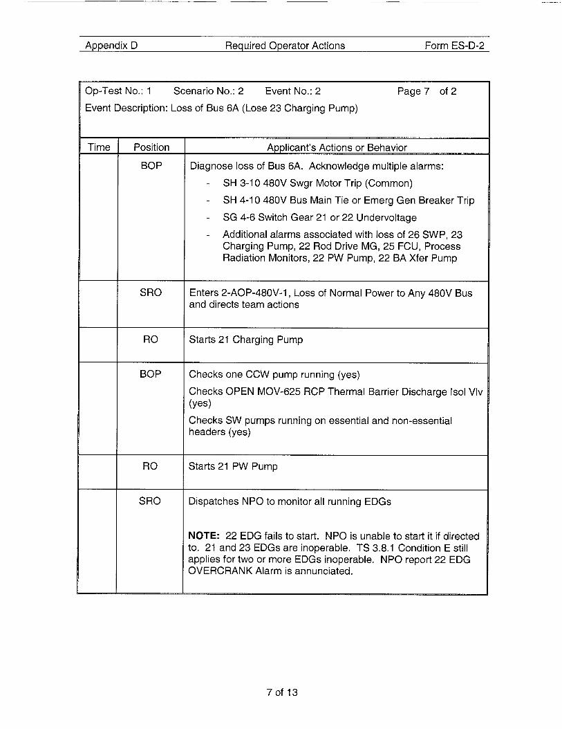
Event Description: Loss of Bus 6A (Lose 23 Charging Pump)
RO
BOP
RO
SRO
App l l can t ' sons or Behavior - Diagnose loss of Bus 6A. Acknowledge multiple alarms:
SH 3-1 0 480V Swgr Motor Trip (Common)
SH 4-1 0 480V Bus Main Tie or Emerg Gen Breaker Trip
SG 4-6 Switch Gear 21 or 22 Undervoltage
Additional alarms associated with loss of 26 SWP, 23 Charging Pump, 22 Rod Drive MG, 25 FCU, Process Radiation Monitors, 22 PW Pump, 22 BA Xfer Pump
-
-
-
-
Enters 2-AOP-480V-1, Loss of Normal Power to Any 480V Bus and directs team actions
Starts 21 Charging Pump
Checks one CCW pump running (yes)
Checks OPEN MOV-625 RCP Thermal Barrier Discharge Is01 Vlv
Checks SW pumps running on essential and non-essential headers (yes)
(Yes)
Starts 21 PW Pump
Dispatches NPO to monitor all running EDGs
NOTE: 22 EDG fails to start. NPO is unable to start it if directed to. 21 and 23 EDGs are inoperable. TS 3.8.1 Condition E still applies for two or more EDGs inoperable. NPO report 22 EDG OVERCRANK Alarm is annunciated.
7of 13

Amendix D Reauired OPerator Actions Form ES-D-2
Op-Test No.: 1 Scenario No.: 2 Event No.: 2 Page2 o f2
Event Description: Loss of Bus 6A (Lose 23 Charging Pump)
Time I
Position
BOP
SRO
Applicant’s Actions or Behavior
Performs Attachment 3 Restoring Normal Power to 480V Bus 6A: -
-
-
Dispatch NPO to start 23 EDG
Notifies SRO that 23 EDG cannot be started
Diagnoses fault on bus 6A (observes 6A fault lamp extinguished)
Dispatch NPO to open bus 6A MCC breakers and perform visual inspection of Bus 6A
Places Control Switches for Bus 6A loads to pullout:
-
-
SIMULATOR OPERATOWCOMMUNICATOR:
Report that the back of Bus 6A switchgear appears damaged and smells burned.
Refer to attachment 5 “480V Bus Equipment” for loads lost and perform a review of Technical Specifications for required actions
- Refers to TS 3.8.9 Condition A
SI MULATOR OPERATOR: Activate Trigger 3 to insert Trip of 21 Charging Pump when directed by the lead evaluator
8of 13

Amendix D Form ES-D-2
Op-Test No.: 1 Scenario No.: 2 Event No.: 3 Page9 o f4
Event Description: 21 Charging Pump Trips (Loss of all charging)
Time Position
RO
SRO
RO
BOP
BOP
SRO
RO
BOP
SRO
~ ~ _ _ ~ ~~~
Amlicant’s Actions or Behavior
Diagnose trip of 21 Charging Pump
Enter 2-AOP-CVCS-1, Chemical and Volume Control System Malfunction and Directs operator actions
Closes the following valves -
-
-
- LCV-459 Letdown Stop
200A Letdown Orifice 75 GPM
2008 Letdown Orifice 45 GPM
200C Letdown Orifice 75 GPM
Closes 204A Alternate Charging 22 Hot Leg
NOTE: MOV-625 should close at this time
Observe MOV-625 RCP Thermal Barrier Disc CLOSED -
-
Place control switch for MOV-625 in OPEN positon
Determine MOV 625 does not open
Directs team to
- Trip Reactor
- Stop all RCPs
- Goto E-0
4ctuates manual reactor trip
Stops all RCPs
3irects team to perform immediate actions of E-0
9of 13

Appendix D Required Operator Actions Form ES-D-2
Op-Test No.: 1 Scenario No.: 2 Event No.: 4
Event Description: Loss of All AC Power
NOTE: Loss of all AC occurs 60 seconds after reactor is tripped
Position
RO
BOP
SRO
RO
RO
Page2 of 4
Applicant’s Actions or Behavior
Directs team actions in EOPs
Verifies Reactor Trip
Verifies Turbine Trip
Checks status of AC Buses - Determines that no AC bus is energized
Enters EOP ECA-0.0 Loss of All AC Power - Directs team to perform ECA-0.0 immediate actions
Verifies Reactor Trip
Verifies Turbine Trip
Verifies RCS isolated. Observes the following valves CLOSED:
- PRZRPORVS,
- LCV-459, Letdown Stop -
- 200A, B, C, Letdown Isolation valves
21 3, Excess letdown isolation
Establish at least 400 gpm AFW flow to the SGs before SG dry-out occurs (WR level less than 14%)
4lign AFW to SGs using 22 Turbine Drive AFW Pump
Checks Open PCV-1139, steam supply regulator
Manually aligns TD AFW Flow Control Valves
Observes > 400 GPM flow
-
-
- Adjust HCV-1118, steam supply -
10 of 13

Appendix D Required Operator Actions Form ES-D-2
Op-Test No.: 1 Scenario No.: 2 Event No.: 4
Event Description: Loss of All AC Power
Page3 o f4
Position
TEAM
BOP
RO
SRO
Applicant’s Actions or Behavior P
Attempt to restore Power to any 480V Bus
Dispatch NPO to emergency start EDGs
SIMULATOR OPERATOR:
NPO is initially unsuccessful at starting an EDG
Performs 2-AOP-138KV-1, Loss of Power to 6.9KV Bus 5 AND/OR 6
SIMULATOR OPERATOR :
CONED DO provides permission use Feeder 13W92. However, 22EDG will be started by NPO BEFORE bus 5A is restored.
Places Control Switches- in Pull-Out: - CSPumps - SI Pumps
- MDAFWPumps - Turning Gear Oil Pump - Bearing Oil Pump - Turb Aux Oil Pump - CCWPumps - RHRPumps
- FCUS
Dispatch personnel to locally restore AC power
SIMULATOR OPERATORKOMMUNICATOR:
After this step is performed, report back to CCR that 22 EDG is ready to start. When permission is given to start 22 EDG, then delete the air start malfunction MAL-DSG003B and execute batch file bat EDG22-1 .bat to reset and start 22 EDG
ReDort back immediatelv after 22 EDG starts.
11 Of 13

Appendix D Required Operator Actions Form ES-0-2
Op-Test No.: 1 Scenario No.: 2 Event No.: 4
Event Description: Loss of All AC Power
Page4 o f 4
Time Position
TEAM
SRO
Verify equipment loaded onto energized bus:
- MCC24
- MCC24A
- 22 Battery Charger -
- PA system inverter
22 Static Inverter on alternate power
- MCC26C
- MCC211
- 23 Battery Charger
Selects Recovery Procedure based upon conditions - ECA-0.1, Loss of All AC Power Recovery Without SI
Required (expected)
ECA-0.2, Loss of All AC Power Recovery With SI Required (if RCP seals degrade)
-
NOTE:
Terminate the scenario when the transition from ECA-0.0 is made, or at the discretion of the lead examiner.
12 of 13

Shift Turnover
Watch Team Turnover Sheet:
Datemime:
RCS Temp:
RCS Press:
PZR Level:
RCS Total Leakage:
RCS Unidentified Leakage:
Xenon:
EFPD:
PZR Press Control:
PZR Level Control:
Service Water:
Risk Assessment:
TODAY
562 O F
2235 psig
48 %
0.1 gpm
0.1 gpm
Equilibrium
340
Channel 1
Channel 2
3 Header Ops
Condition: Power Ops
% Power: 100%
MW Gross: 1017
River Water: 78 O F
Boron Conc: 972 ppm
Control Rods 214 CBD
Condenser Air leakage 6 SCFM
RCS Gas activity 2.54e-2 pCi/cc
Yellow Daily Risk Factor: 3.45
Plant Equipment Status:
1. EDG 21 is out of service for bearing replacement. It was removed from service 42 hours ago and is due back in 12 hours. Maintenance is currently performing repairs. TS 3.8.1.B surveillance (2ptw 19) requirement last performed 3 hours ago.
2. 21 and 22 EDGs are protected equipment. 3. 22 Charging Pump was removed from service for corrective maintenance 18 hours ago.
Expected return to service in 35 hours.
Instructions to the Shift: Maintain current plant conditions.
Page 13 of 13
Appendix D Scenario Outline Form ES-D-1
XMT- SG N026A
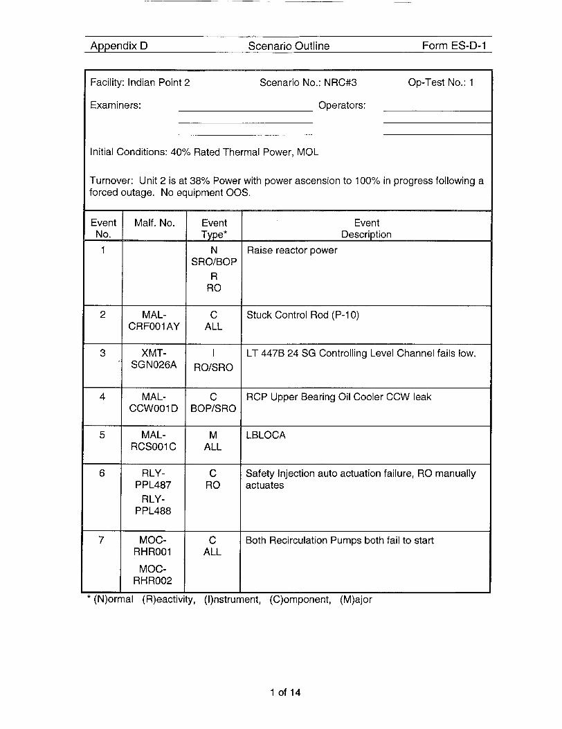
Facility: Indian Point 2 Scenario No.: NRC#3 Op-Test No.: 1
I RO/SRO
Examiners: Operators:
MAL- CCWOO1 D
Initial Conditions: 40% Rated Thermal Power, MOL
C BOP/SRO
Turnover: Unit 2 is at 38% Power with power ascension to 100% in progress following a forced outage. No equipment 00s.
MAL- RCS001 C
Event No. 1
2
M ALL
3
RLY- PPL487
RLY- PPL488
4
C RO
5
MOC- RHR001
MOC- RH ROO2
6
C ALL
7
MAL- C CRF001 AY ALL
Event Description
Raise reactor power
Stuck Control Rod (P-IO)
LT 4478 24 SG Controlling Level Channel fails low.
RCP Upper Bearing Oil Cooler CCW leak
LBLOCA
Safety Injection auto actuation failure, RO manually actuates
Both Recirculation Pumps both fail to start
I
(N)ormal (R)eactivity, (I)nstrument, (C)omponent, (M)ajor
1 of 14

Simulator Setup
Reset to IC-125
Execute batch file Bat "NRC3.bat from Ph.D Expert window:
A MAL-CRF001 AY ROD: P10 STUCK ROD IMF MAL-CRF001AY (-1 0) 1 A RLY-PPL487 RELAY FAILURES: SIA-1 (A) SAFETY INJECTION AUTO MASTE IMF RLY-PPL487 (-1 0) 2 A RLY-PPL488 RELAY FAILURES: SIA-2 (6) SAFETY INJECTION AUTO MASTE IMF RLY-PPL488 (-1 0) 2
IMFMOC-RHR001 (-1 0) 5
IMF MOC-RHR002 (-1 0) 5 AXMT-SGNO26A FIXED OUTPUT: LT-4476 S/G 24 LEVEL IMF XMT-SGN026A (1 0) 0.000000 0 48.796101 A MAL-CCW001 D RCP 24 OIL COOLER TUBE LEAK (NR) IMF MAL-CCW001 D (2 0) 1 .OOOOOO 180 0.000000
IMF MAL-RCS001 C (30 0) TRUE
A MOC-RHR001 R1 RECIRC PUMP NO. 21 MOTOR
A MOC-RHR002 R2 RECIRC PUMP NO. 22 MOTOR
A MAL-RCS001C RUPTURE LOOP C COLD LEG (N R)
A Set Up trigger to actuate LBLOCA when Rx Trips TRGSET 30 "j b krta.eq.0"
Verify the following commands appear in the instructor station summary:
'T'FPILCIRES SIA-1 (A) S4 oooooo O O O O ~ O None n/a aturk cnntactc 00 00 00 ~'FAIltlfiEIS SIA-Z(F) SA nonnoo ononnn PJnn? n i b durh contartc ' i o no on
RECIRC PUMP YO 21 000000 000000 None nla asis 000000 FiEClkCPUMP NO 2 asis U O D O O 0
IXED OUTPUT LT-4178 S,' 48 3509 0 OU 30 00 RCF 24 OIL COOLER TUBE LEAK UPTl.IRE LOOP C COL@ LEG FPLS E FPLSE 0 0 0 0 0 0
-. I
.. .. ........... . . . . . . . 1
TRUE
FALSE I - - . . - . . . . -. .. -. ..... - .....................
2of 14

Simulator Setup
Verify that conditional trigger 30 appears as follows
g i y . r - , P i I ’
Ih, I._, n*
Event# Event Action i
3of 14

Appendix D Required Operator Actions Form ES-D-2
Op-Test No.: 1 Scenario No.: 3 Event No.: 1
Event Description: Raise reactor power
Page1 of 1
Time Position
SRO
RO
BOP
Applicant’s Actions or Behavior - Directs activities associated with power increase per 2-POP-1.3, “Plant Startup, Mode 2 to Mode 1”:
- Rod Motion
- Dilution
- Turbine Load
Adds Positive reactivity
- Rod Motion
- Dilution
Raises turbine load using Turbine Governor (or LLl/LL2 if directed)
CUE: Generator Flux surveys have been performed. Extraction steam Bypass valves are closed.
Fuel conditioning 3% per hour limit on power increase is not required.
If questioned about the MBFP seal water injection pump, I&C is investigating the low delta-P alarm setpoint.
EVALUATOR NOTE: Proceed to the next event after sufficient rod motion has resulted in positive indication of rod misalignment
4of 14 NUREG-1021, Draft Revision 9
Appendix D Required Operator Actions Form ES-D-2
Position
RO
BOP
SRO
RO
SRO
RO
BOP
SRO
RO
Applicant’s Actions or Behavior _5
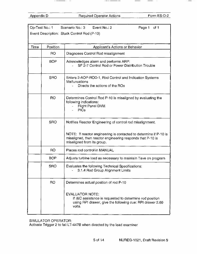
Diagnoses Control Rod misalignment
Acknowledges alarm and performs ARP: - SF 2-7 Control Rod or Power Distribution Trouble
Enters 2-AOP-ROD-1, Rod Control and Indication Systems Malf uncations
- Directs the actions of the ROs
Determines Control Rod P-10 is misaligned by evaluating the following indications:
- Flight Panel DVM - PlCS
Notifies Reactor Engineering of control rod misalignment.
NOTE: If reactor engineering is contacted to determine if P-10 is misaligned, then reactor engineering responds that P-10 is misaligned from its group.
Places rod control in MANUAL
Adjusts turbine load as necessary to maintain Tave on program
Evaluates the following Technical Specifications: 3.1.4 Rod Group Alignment Limits -
Determines actual position of rod P-10
EVALUATOR NOTE: If I&C assistance is requested to determine rod position using RPI drawer, give the following cue: RPI drawer 2.60 volts.
SI MU LATOR OPERATOR: Activate Trigger 2 to fail LT-4476 when directed by the lead examiner
5of 14 NUREG-1021, Draft Revision 9

Appendix D Required Operator Actions Form ES-D-2
Op-Test No.: 1 Scenario No.: 3 Event No.: 3 Page 1 of 1 Event Description: LT 4478, 24 SG Controlling Level Channel fails low.
Time
*
Position
RO
BOP
SRO
RO
SRO
BOP
Applicant’s Actions or Behavior - P
Diagnoses 24 SG Level control deviation
Performs ARP for associated alarms: -
- FB 1-1 Steam Generator Level Control Deviation
SB-2 4-3 24 SG Low Level Channel Trip
Directs RO to perform immediate action of 2-AOP-INST-I , Instrument/Controller Failures
Diagnoses failure of LT-447B, 24 SG controlling level channel - Places 24 SG Feedwater Regulating Valve controller in
Manual and adjusts FRV position as necessary to control 24 SG level at program.
Evaluates the following Technical Specifications: -
-
-
3.3.1 Table 1 Function 13 (condition E applies)
3.3.2 Table 1 Functions 5.b and 6.b (condition D applies)
Determines that bistable must be tripped within 72 hours per 3.3.1 Condition E and 3.3.2 Condition D
Places bistable trip switches in trip: -
- LC-447E, Loop 4B High Level, in Foxboro Blue Rack 8-2
LC-447F, Loop 4B Low Level, in Foxboro Blue Rack B-2
* EXAMINER NOTE: the next event takes -6 minutes until the first alarm providing a cue to the operator. Therefore, the next malfunction should be activated accordingly.
SIMULATOR OPERATOR: Insert the next malfunction by activating trigger 2 to cause RCP Upper Bearing Oil Cooler CCW leak when directed by the lead evaluator.
6o f 14 NUREG-1021, Draft Revision 9

Appendix D Required Operator Actions Form ES-D-2
Position
BOP
SRO
BOP
BOP
SRO
SRO
RO
BOP
SRO
Acknowledge alarm and perform ARP: -
-
-
SA 3-1, Reactor Coolant Pump Motor Bearing Oil High Level 1.25 Observes status light and identifies 24 RCP Upper bearing High lamp illuminated Monitors motor bearing temperatures and vibration
Enters 2-AOP-RCP-1 Reactor Coolant Pump Malfunctions and directs the actions of the team
Event Description: RCP Upper Bearing Oil Cooler CCW leak
Monitors the following parameters: - Stator Winding Temperature - #1 Seal Delta-P - RCP Vibrations - RCP Motor Bearing Temperatures - #I Seal Inlet Temperatures
Notifies the SRO WHEN RCP Motor Bearing Temperatures exceed 200°F (or at a lower value provided by the SRO)
NOTE: RCP BRG Temp High Alarm at 180F
Monitors RCP motor bearing temperatures and notifies the SRO when 24 RCP motor bearing temperature is >= 185°F
When 24 RCP motor bearing temperature >= 185"F, INITIATES plant shutdown using POP-3.1 (with goal of stopping 24 RCP prior to reaching 200°F)
When 24 RCP temperatures reach 200°F (or earlier if a band is provided by the SRO) directs the team to trip the Reactor, Stop 24 RCP and INITIATE EOP E-0
Trips the reactor
Stops 24 RCP
Directs team to perform immediate actions of EOP E-0, Reactor Trip or Safety Injection
EXAMINER NOTE: Proceed to the next event after the reactor is tripped. The LBLOCA will occur automatically from the reactor trip.
7of 14 NUREG-1021, Draft Revision 9
Appendix D Required Operator Actions Form ES-D-2
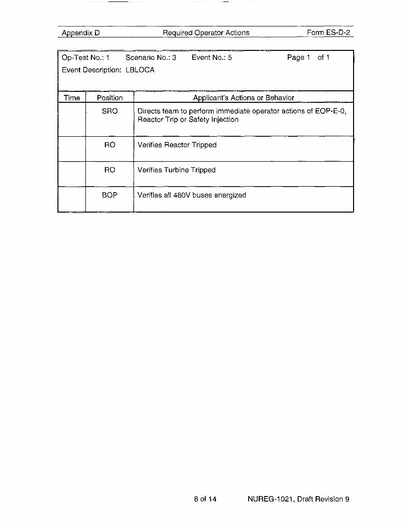
Event Description: LBLOCA
Directs team to perform immediate operator actions of EOP-E-0, Reactor Trip or Safety Injection
Verifies Reactor Tripped
Verifies Turbine Tripped
Verifies all 480V buses energized
80f 14 NUREG-1021, Draft Revision 9

Appendix D Required Operator Actions Form ES-D-2
Op-Test No.: 1 Scenario No.: 3 Event No.: 6 Page1 o f3
Event Description: Safety Injection auto actuation failure, RO manually actuates
._
Time __p
Position
RO
BOP
Checks Status of Safety Injection -
- Determines that neither train of SI is actuated
Manually actuates both trains of Safety Injection
Performs Attachment 1 while SRO and RO continue in E-0: Verify charging system operation - - Closes LC-l12C, place Makeup Control Switch to STOP) Check 345 KV MO Disc Switch F7-9 Open -
Check status of 480 V buses - and 29A - Stops all Condensate Pumps Verify FW Isolation Check if MSlVs should be isolated Check SW system operation Check SI System Operation Check SI system valve aligment Verify Containment Fan Coolers in service Verify AFW Flow to all SGs Verify Containment Ventilation Isolation Verify Containment Isolation Phase A Check if CS status Verify CCR Air Conditioner status Notify SRO Attachment 1 complete
Starts one charging pump in manual at maximum speed Align charging system to the RWST (opens LCV-l12B,
verifes BKR 7 and 9 open
Dispatches NPO to reset all lighting and MCCs 24A, 27A,
9of 14 NUREG-1021, Draft Revision 9

Appendix D Required Operator Actions Form ES-D-2
Op-Test No.: 1 Scenario No.: 3 Event No.: 6 Page2 of 3
Event Description: Safety Injection auto actuation failure, RO manually actuates
Position
RO ~
RO
SRO
RO
SRO/RO
SRO
A p p l i c a n t ’ m n s or Behavior
Observes RCS Subcooling less than 30°F and at least one SI Pump Running
Stops all RCPs
-
Verifies AFW Pumps running and supplying > 400 GPM AFW flow to the SGs
Verifies SI Pump flow and RHR pump flow
Checks RCP seal cooling
Starts 22 SWP
Controls RCS Cool-Down by verifying not dumping steam, reducing AFW flow to >400gpm check MSlVs closed
Checks PORVS and Spray Valves closed
Dispatches NPO to close SWN-4 and SWN-5 in the Zurn strainer pit
Checks for Faulted and ruptured SGs
Diagnose RCS is not intact
Transition to EOP E-1 , Loss of Reactor or Secondary Coolant
10 of 14 NUREG-1021, Draft Revision 9

Appendix D Required Operator Actions Form ES-D-2
Op-Test No.: 1 Scenario No.: 3 Event No.: 6 Page3 o f3
Event Description: Safety Injection auto actuation failure, RO manually actuates
Position
RO
BOP
RO
BOP
SRO
Applicant’s Actions or Behavior
Verifies RCPs stopped
Check for any faulted SG
Checks SG levels and maintains >400gpm until one SG level >
Opens one Block Valve
27%
Resets SI
Resets Phase A and Phase B
Opens PCV-1228 to supply IA to containment
Check for ruptured SG
Check charging flow
Notifies team when RWST level c 9.24 feet
Transitions to ES-1.3, Transfer to Cold Leg Recirculation
11 of 14 NUREG-1021, Draft Revision 9

Appendix D Required Operator Actions Form ES-D-2
Event Description: Both Recirculation Pumps both fail to start
Position
Team
SRO
RO
SRO
RO
Verify SI reset (Resets SI if not previously performed)
Dispatch NPO to fully open SWN-35 and SWN-35-1 CCW Heat Exchanger SW Outlet valves
Stop all Charging Pumps
Turn off all PRZR Heaters
Reset Containment Spray
Place Recirc Switches 1 and 3 to ON
Check SW aligned for three header
Check SWN-4 an SWN-5 have been closed
Place SI Recirc Switch 2 to ON
Check Containment Sump Level Greater than 47’1 0”
Place SI Recirc Switch 4 to ON - - -
Determines 21 Recirculation Pump will not start Attempts to manually start 22 Recirculation Pump Determines neither Recirculation Pump can be started
Transfer to cold-leg recirculation and establish minimum required ECCS recirculation flow per ES-1.3 Step 10 Table prior to core uncovery based upon RVLIS indication (41 %).
Performs Attachment 2 Cold Leg Recirculation Using RHR Pumps
Establish Cold Leg Recirculation Using RHR Pumps
Check 885A and 8858 both energized -
12of 14 NUREG-1021 Draft Revision 9

Appendix D Required Operator Actions Form ES-D-2
Op-Test No.: 1 Scenario No.: 3 Event No.: 7 Page2 of 2
Event Description: Both Recirculation Pumps both fail to start
I SRO 1 Return to ES-1.3 step 10
Determine if adequate low head recirculation flow has been established
Checks flow indicators 946A-D and provides values to SRO
Place SI Recirc Switch 7 to ON
Place SI Recirc Switch 8 to ON
EXAMINER NOTE: Terminate the scenario after adequate Recirc flow has been established and verified, or at the Lead Examiner’s discretion.
13 of 14 NUREG-1021, Draft Revision 9
Shift Turnover
Watch Team Turnover Sheet:
Datemime:
RCS Temp:
RCS Press:
PZR Level:
RCS Total Leakage:
RCS Unidentified Leakage:
Xenon:
EFPD:
PZR Press Control:
PZR Level Control:
Service Water:
Risk Assessment:
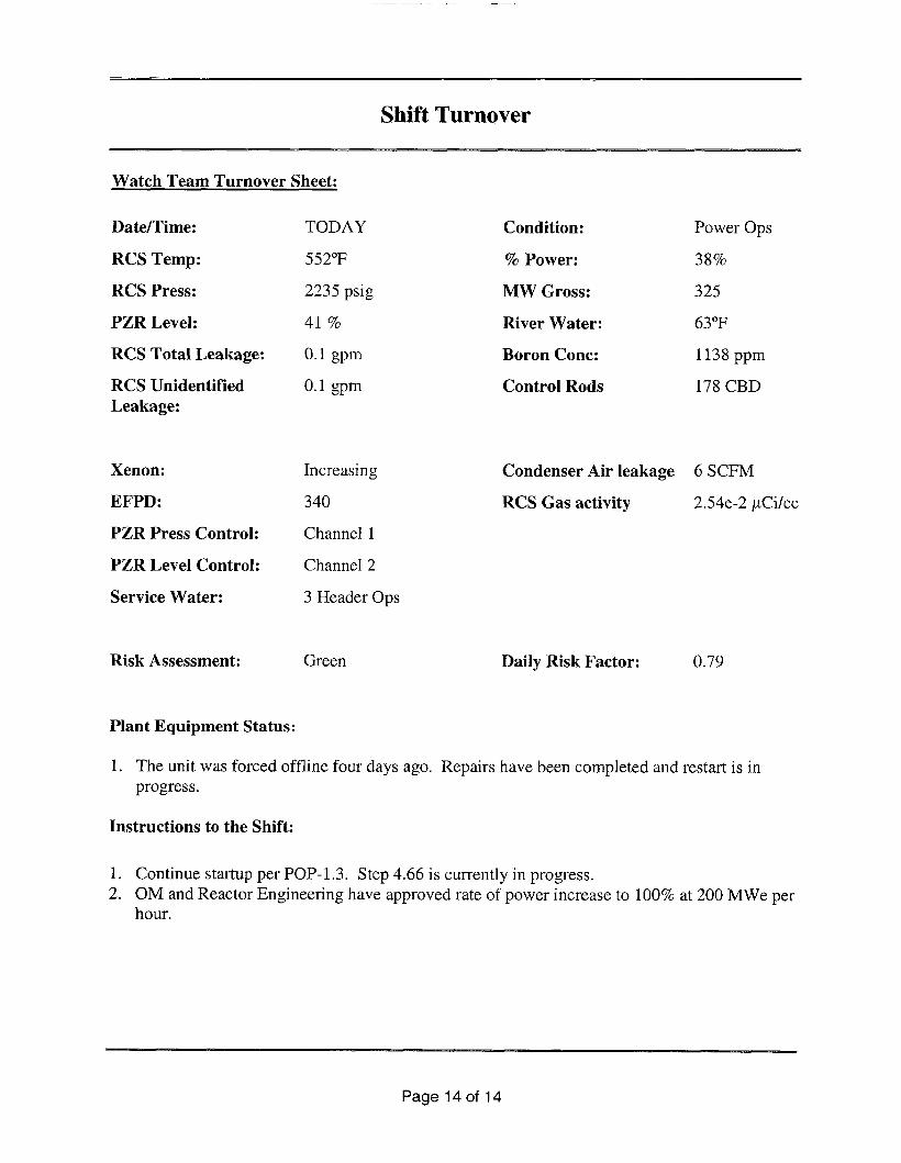
TODAY
552°F
2235 psig
41 %
0.1 gpm
0.1 gpm
Increasing
340
Channel 1
Channel 2
3 Header Ops
Green
Condition: Power Ops
% Power: 38%
MW Gross: 325
River Water: 63°F
Boron Conc: 1138 ppm
Control Rods 178 CBD
Condenser Air leakage 6 SCFM
RCS Gas activity 2.54e-2 pCi/cc
Daily Risk Factor: 0.79
Plant Equipment Status :
1. The unit was forced offline four days ago. Repairs have been completed and restart is in progress.
Instructions to the Shift:
1. Continue startup per POP-1.3. Step 4.66 is currently in progress. 2. OM and Reactor Engineering have approved rate of power increase to 100% at 200 MWe per
hour.
Page 14 of 14

Appendix D Scenacio Outline Form ES-D-1
-Facility: Indian Point 2 Scenario No.: NRC#4 Op-Test No.: 1
Examiners: Operators:
Initial Conditions: 100% Rated Thermal Power, MOL. 21 EDG is out of Service. 21 Charging Pump is out of service.
Turnover: Unit 2 is at 100% Power steady state conditions 340 EFPD. 21 EDG is out of service and has been inoperable for 42 hours. Maintenance is currently performing repairs.
In addition, 22 Charging Pump was removed from service for corrective maintenance 18 hours ago. Expected return to service in 35 hours.
RCS002A
* (N)ormal (R)eactivity,
Event Type*
N
ALL
C BO P/S RO
R RO
I ALL
M ALL
C RO/SRO
(1)nstrumer
Event Description
Raise main generator reactive load (MVARS)
23 Condensate Pump trips Reduce steam flow<Feed Flow Reduce Tave using boration and rod insertion
VCT Level Transmitter fails low
Faulted Steam Generator Reactor auto and manual trips fail to actuate
~ ~ ~ ~
PORV Fails Open. Block valve used to isolate it.
, (C)omponent, (M)ajor
1 of 11
Simulator Setut,
1. 2.
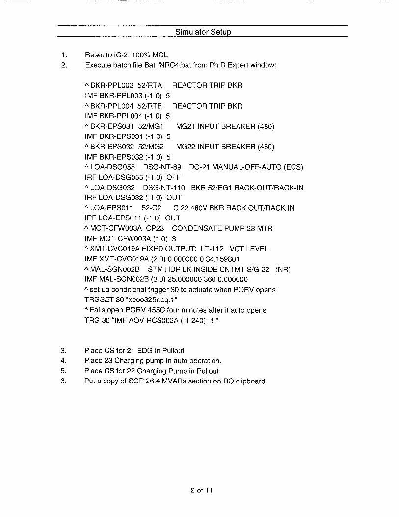
Reset to IC-2, 100% MOL Execute batch file Bat "NRC4.bat from Ph.D Expert window:
A BKR-PPL003 52/RTA REACTOR TRIP BKR IMF BKR-PPL003 (-1 0) 5 A BKR-PPL004 52/RTB REACTOR TRIP BKR IMF BKR-PPL004 (-1 0) 5 A BKR-EPS031 52/MG1 MG21 INPUT BREAKER (480) IMFBKR-EPS031 (-1 0) 5 A BKR-EPS032 52/MG2 IMF BKR-EPS032 (-1 0) 5 A LOA-DSG055 DSG-NT-89 DG-21 MANUAL-OFF-AUTO (ECS) IRF LOA-DSG055 (-1 0) OFF A LOA-DSG032 DSG-NT-110 BKR 52/EG1 RACK-OUT/RACK-IN IRF LOA-DSG032 (-1 0) OUT A LOA-EPSO1 1 52-C2 IRF LOA-EPSO11 (-1 0) OUT A MOT-CFW003A CP23 IMF MOT-CFW003A (1 0) 3 A XMT-CVCOl9A FIXED OUTPUT: LT-112 VCT LEVEL IMF XMT-CVCO19A (2 0) 0.000000 0 34.159801 A MAL-SGN002B STM HDR LK INSIDE CNTMT S/G 22 (NR) IMF MAL-SGN002B (3 0) 25.000000 360 0.000000
MG22 INPUT BREAKER (480)
C 22 480V BKR RACK OUT/RACK IN
CONDENSATE PUMP 23 MTR
* set up conditional trigger 30 to actuate when PORV opens TRGSET 30 "xeoo325r.eq.l 'I * Fails open PORV 455C four minutes after it auto opens TRG 30 "IMF AOV-RCS002A (-1 240) 1 'I
3. 4. 5. 6.
Place CS for 21 EDG in Pullout Place 23 Charging pump in auto operation. Place CS for 22 Charging Pump in Pullout Put a copy of SOP 26.4 MVARs section on RO clipboard.
2of 11

Simulator Setup
EkR-PPL004 S?/RTB REACTOR TRiP B’J3 00 00 00 00 00 00 None fbl *LIS 00 00 00 BKH-EPS031 5PlMGl MG?l INWTRPEAI’EP. 00ODDO 0 0 0 0 0 0 None nia fali 00 no 00
FPSO3Z 52:MGZ M G E 2 lNMJTBP.Ex<Fii (io 03 00 ii(i rici on I\lonp n/a fell AElS r10 00 00
-om 9 4 FIXED IOIJTFI JT L T-i 1 ? L’C Oil Ill1 no 00 00 Oil 2 34 1w 11 00 loll [Ill -SGt.IOO:G ZTTM t IDR A INSIDE CNTbiT S/C E n o o o o o O O O E O O 3 0 :5 0 o o o o o
CF#003A W E 3 C€JND€N%TE PUMP23 000000 0 0 0 0 0 0 1 n:o winding short 00 00 00
I Triggers
I
I
TRUE
FALSE
17 Available 18 Available 19 Available 20 Available 21 Available 22 Available 23 Available 24 Available 25 Available 26 Available 27 Available 28 Available
I
TRUE
FALSE
3o f 11
Appendix D Required Operator Actions Form ES-D-2
~
Position
CRS
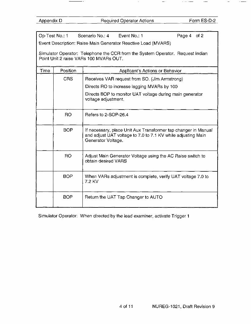
Op-Test No.: 1 Scenario No.: 4 Event No.: 1 Page4 o f2
Event Description: Raise Main Generator Reactive Load (MVARS)
Simulator Operator: Telephone the CCR from the System Operator. Request Indian Point Unit 2 raise VARs 100 MVARs OUT.
RO
BOP
RO
BOP
BOP
~~~~~
Atmlicant’s Actions or Behavior
Receives VAR request from SO. (Jim Armstrong)
Directs RO to increase lagging MVARs by 100
Directs BOP to monitor UAT voltage during main generator voltage adjustment.
Refers to 2-SOP-26.4
If necessary, place Unit Aux Transformer tap changer in Manual and adjust UAT voltage to 7.0 to 7.1 KV while adjusting Main Generator Voltage.
Adjust Main Generator Voltage using the AC Raise switch to obtain desired VARS
When VARs adjustment is complete, verify UAT voltage 7.0 to 7.2 KV
Return the UAT Tap Changer to AUTO
Simulator Operator: When directed by the lead examiner, activate Trigger 1
4of 11 NUREG-1021, Draft Revision 9

Appendix D Required Operator Actions Form ES-D-2
Op-Test No.: 1 Scenario No.: 4 Event No.: 2 Page1 of 1 Event Description: 23 Condensate Pump trips, Reduce Steam flow<Feed Flow, Reduce Tave using boration and rod insertion
SI MU LATO R OPE RATOR: Activate Trigger 1 when directed by Lead Examiner to start event.
Time - Position
BOP
SRO
RO
SRO
RO
BOP
RO
Applicant’s Actions or Behavior
Diagnoses trip of 23 Condensate Pump
Directs RO to perform immediate actions of 2-AOP-FW-1, Loss of Main Feedwater
Verifies Main Feedwater Pumps running
Directs team actions using 2-AOP-FW-1 , Loss of Main Feedwater
Reduces turbine load as necessary to maintain Feed Flow 2 Steam Flow
Adds negative reactivity using boration and/or control rods to maintain Tave on program
Monitors delta-flux during reactivity addition and uses control rods when required to maintain delta-flux within the target band
Monitors MBFP suction pressure and if suction pressure cutback actuates, then places MBFP Master Speed Controller in MANUAL and slowly lowers MBFP speed to maintain suction pressure > 31 0 psig
EXAMINER NOTE: Suction pressure will not immediately respond after manual action is taken: Suction pressure will respond after Feed Flow is > Steam Flow AND the Main Feed Regulating Valves begin to throttle closed.
Places Main Feed Regulating Valve controllers to manual as necessary and controls feed flow when level in SG > 60% or when controller windup is to be removed.
Places Main Boiler Feed Pump Master Controller back to automatic using SOP 21.1
SIMULATOR OPERATOR: Activate trigger 2 when directed by the Lead Examiner to proceed to event 2: VCT Level Transmitter fails low
5of 11 NUREG-1021, Draft Revision 9

Appendix D Required Operator Actions Form ES-D-2
Op-Test No.: 1 Scenario No.: 4 Event No.: 3
Event Description: VCT Level Transmitter fails low
Page 1 of 1
BOP
RO
BOP
Applicant’s Actions or Behavior
Diagnoses VCT Level Transmitter failure
Enters 2-AOP-CVCS-1, Chemical and Volume Control System Malfunctions, and directs the operator’s actions
Holds LCV-112C Control Switch in OPEN
When LCV-112C indicates open, then CLOSES LCV-1128
Places Makeup Control Switch in STOP
If necessary, reduces turbine load to keep Tave on program
When necessary to raise VCT pressure, initiates manual VCT makeup per SOP-3.2, Reactor Coolant System Boron Concentration Control
Monitors VCT Pressure. Controls VCT pressure 2-5 psig above pre-malfunction (1 9-20 psig) pressure as follows:
- Coordinates with RO to raise VCT Pressure by manual makeup to VCT per SOP-3.2, Reactor Coolant System Boron Concentration Control
Lowers VCT Pressure by manually diverting letdown via - LCV-112A
SIMULATOR OPERATOR: When directed by the Lead Examiner, actuate trigger 3 to cause Faulted Steam Generator, Reactor auto and manual trips fail to actuate
6of 11 NUREG-1021, Draft Revision 9

Appendix D Required Operator Actions Form ES-D-2
actuate
Diagnose failure of reactor to trip
SIMULATOR OPERATOR: Trip both Rod Drive MG set Output Breakers to insert control rods at this time.
7of 11 NUREG-1021, Draft Revision 9

Appendix D Required Operator Actions Form ES-D-2
Op-Test No.: 1 Scenario No. 4: Event No.: 4 Page2 o f 2 Event Description: Faulted Steam Generator, Reactor auto and manual trips fail to
actuate
Verify Containment Ventilation Isolation
Verify Containment Pressure Relief Valves Closed
I I RO I Check reactor trip and turbine trip have occurred
Maintain total feed flow > 800 gpm until NR level in at least one SG > 10%
1 RO I Verify all dilution paths isolated: - Check FCV-111 A demin water flow control valve
CLOSED
Check no flow indicated on FI-11 1 Primary Water Flow - Check for Reactivity Insertion from Uncontrolled RCS Cooldown
RO Check CETs e 120OOF
Verify Reactor Subcritical
I I SRO 1 Return to EOP E-0, Reactor Trip or Safety Injection
8of 11 NUREG-1021, Draft Revision 9

Appendix D Required Operator Actions Form ES-D-2
L
Op-Test No.: 1 Scenario No.: 4 Event No.: 5 Page 1 o f 2
Event Description: PORV Fails Open. Block valve used to isolate it.
Time Position
RO
BOP
RO
BOP
Applicant’s Actions or Behavior
Verify Reactor Trip
Verify Turbine Trip
Verify power to 480V Buses
Verify SI Status
Performs Attachment 1 while SRO and RO continue in E-0: Verify charging system operation - - Closes LC-11 2CJ place Makeup Control Switch to STOP)
Check 345 KV MO Disc Switch F7-9 Open - Check status of 480 V buses - and 29A
- Stops all Condensate Pumps
Verify FW Isolation
Check if MSlVs should be isolated
Check SW system operation
Check SI System Operation
Check SI system valve aligment
Verify Containment Fan Coolers in service
Verify AFW Flow to all SGs
Verify Containment Ventilation Isolation
Verify Containment Isolation Phase A
Check if CS status
Verify CCR Air Conditioner status
Starts one charging pump in manual at maximum speed
Align charging system to the RWST (opens LCV-1128,
verifes BKR 7 and 9 open
Dispatches NPO to reset all lighting and MCCs 24AJ 27AJ
Notify SRO Attachment 1 complete
9of 11 NUREG-1021, Draft Revision 9

Appendix D Required Operator Actions Form ES-D-2
Op-Test No.: 1 Scenario No.: 4 Event No.: 5 Page2 o f 2
Event Description: PORV Fails Open. Block valve used to isolate it.
I Ro + TEAM
I SRO
I TEAM I CRS
EXAMINER NOTE:
Amlicant's Actions or Behavior
Verifies AFW Pumps running and supplying > 400 GPM AFW flow to the SGs
Verifies SI Pump flow and RHR pump flow
Checks RCP seal cooling
Starts 22 SWP
Controls RCS Cool-Down by verifying not dumping steam, reducing AFW flow to >400gpm and closing MSlVs
Check if RCPs should be stopped
Checks for any faulted SG
Transitions to E-2, Faulted SG Isolation
Verify all actions to isolate 22 SG have been completed
Transition to E-1 , Loss of Reactor or Secondary Coolant
Verify that SI Termination Criteria are met
Transition to ES-1 .l, SI Termination
Terminate the scenario when transition to ES-1.1 is made, or at the discretion of the Lead Examiner
10 of 11 NUREG-1021, Draft Revision 9

Shift Turnover _ _ ~
Watch Team Turnover Sheet:
Date/Time:
RCS Temp:
RCS Press:
PZR Level:
RCS Total Leakage:
RCS Unidentified Leakage:
Xenon:
EFPD:
PZR Press Control:
PZR Level Control:
Service Water:
Risk Assessment:
TODAY
562 O F
2235 psig
48 %
0.1 gpm
0.1 gpm
Equilibrium
340
Channel 1
Channel 2
3 Header Ops
Condition: Power Ops
% Power: 100%
MW Gross: 1017
River Water: 78 O F
Boron Conc: 972 ppm
Control Rods 214 CBD
Condenser Air leakage 6 SCFM
RCS Gas activity 2.54e-2 pCi/cc
Yellow Daily Risk Factor: 3.45
Plant Equipment Status:
1. EDG 21 is out of service for bearing replacement. It was removed from service 42 hours ago and is due back in 12 hours. Maintenance is currently performing repairs. TS 3.8.1.B surveillance requirement last performed 3 hours ago.
2. 21 and 22 EDGs are protected equipment. 3. 22 Charging Pump was removed from service for corrective maintenance 18 hours ago.
Expected return to service in 35 hours.
Instructions to the Shift: Maintain current plant conditions.
Page 11 of 11