draft rfp notice to reviewer - ct.gov … rfp notice to reviewer this document is being provided for...
TRANSCRIPT
DRAFT RFP NOTICE TO REVIEWER
This document is being provided for review and comment by the interested parties. The sections and attached provisions
are at various stages of draft and may undergo minor or extensive revisions prior to the issuance of the RFP by the
Department.
The Department invites all interested parties to comment on the draft documents by email to:
The Email subject line must be as follows:
{Date} {Project number} {Proposer name} ”RFP Comments”
In the body of the email explain the comment citing specific part, page, detail heading and other related identifying
information and then state the question. As an alternate the body of the email may briefly explain that the comment(s)
and identifying information is attached.
i
REHABILITATION OF BRIDGE NOS. 02366, 02367, AND 02369 IN EAST HARTFORD AND
BRIDGE NO. 00847 IN WILLINGTON
EAST HARTFORD AND WILLINGTON, CONNECTICUT
Project No. 171-431
DESIGN-BUILD PROCUREMENT
REQUEST FOR PROPOSALS
TECHNICAL PROVISIONS
September 13, 2016
i
CONNECTICUT DEPARTMENT OF TRANSPORTATION
REHABILITATION OF BRIDGE NOS. 02366, 02367, AND 02369
IN EAST HARTFORD AND BRIDGE NO. 00847 IN
WILLINGTON, CONNECTICUT
DESIGN-BUILD PROCUREMENT
REQUEST FOR PROPOSALS
TECHNICAL PROVISIONS
TABLE OF CONTENTS
DRAFT RFP NOTICE TO REVIEWER ....................................................................................................................
{Date} {Project number} {Proposer name} ”RFP Comments” ...................................................................
Project Requirements and Provisions for Work ........................................................... 1
1.1. PROJECT MANAGEMENT ............................................................................................................................... 1
1.1.1. Project Overview ....................................................................................................... 1
1.1.2. General ..................................................................................................................... 3
1.1.3. Project Management ................................................................................................. 3
1.1.4. Department’s Role .................................................................................................... 4
1.1.5. Federal Highway Administration’s (FHWA) Role ....................................................... 4
1.2. REFERENCE DOCUMENTS AND STANDARDS ...................................................................................... 4
1.2.1. BTC-Related Reference Documents ......................................................................... 4
1.2.2. AASHTO, Department, and Other Applicable Standards ........................................... 5
1.2.3. Preliminary Design Documents ................................................................................. 5
1.2.4. Historical Documents ................................................................................................ 5
1.3. ADMINISTRATION AND COORDINATION .............................................................................................. 5
1.3.1. Introduction ............................................................................................................... 5
1.3.2. Police, Fire, Public Transit, CTDOT Highway Operations, Town Officials and Emergency................................................................................................................ 7
1.3.3. Coordination with Other Projects ............................................................................... 8
1.3.4. Coordination of Traffic Officers .................................................................................. 9
1.4. RISK MANAGEMENT........................................................................................................................................ 9
1.4.1. Utilities .................................................................................................................... 10
1.4.2. Right of Way ........................................................................................................... 10
1.4.3. Geotechnical ........................................................................................................... 10
1.4.4. Construction/Traffic Sequencing and Staging ......................................................... 10
1.4.5. [Roadways or Features Spanned] ........................................................................... 11
ii
1.4.6. Hazardous Materials ............................................................................................... 11
1.4.7. Community Impacts ................................................................................................ 11
1.5. PROJECT CONTROLS .................................................................................................................................... 11
1.5.1. Electronic Document Management ........................................................................ 11
1.5.2. Change Management ............................................................................................. 11
1.5.3. Schedule Management ........................................................................................... 12
1.5.4. Project Safety ......................................................................................................... 12
1.6. QUALITY MANAGEMENT ........................................................................................................................... 12
1.6.1. General ................................................................................................................... 12
1.6.2. Approach to Quality Matters .................................................................................... 12
1.6.3. Quality Management ............................................................................................... 13
1.6.4. Quality Control ........................................................................................................ 13
Information Supplied To Contractor/ Acknowledgement by the Contractor ... 14
2.1. GENERAL ........................................................................................................................................................... 14
2.2. DEPARTMENT-SUPPLIED DESIGN ELEMENTS AND DOCUMENTATION .............................. 14
Project Design and Construction ....................................................................................... 15
3.1. GENERAL DESCRIPTION AND EXISTING CONDITIONS ................................................................. 15
3.2. WORK AT RISK ................................................................................................................................................ 15
3.3. CODES, STANDARDS AND SPECIFICATIONS ...................................................................................... 15
3.3.1. General Exceptions: ................................................................................................ 15
3.3.2. Mandatory Special Provisions: ................................................................................ 16
3.3.3. Guidance Special Provisions:.................................................................................. 16
3.3.4. Other Special Provisions: ........................................................................................ 16
3.4. DESIGN REVIEWS AND SUBMITTALS ................................................................................................... 17
3.4.1. Department Reviews ............................................................................................... 17
3.4.2. Over-the-Shoulder Reviews .................................................................................... 17
3.4.3. Comment Resolution Meeting ................................................................................. 17
3.4.4. Design Submittal Review Process .......................................................................... 18
3.4.5. Design Documents .................................................................................................. 20
3.5. EARLY RELEASE CONSTRUCTION PROCESS ..................................................................................... 21
3.6. CONSTRUCTION STAGING ......................................................................................................................... 23
3.6.1. General Approach ................................................................................................... 23
3.6.2. Road Closure Readiness Packages ........................................................................ 24
3.7. BID ITEMS ......................................................................................................................................................... 25
3.7.1. Estimated Quantity Items ........................................................................................ 25
iii
3.7.2. Estimated Cost Items .............................................................................................. 25
3.8. SURVEY .............................................................................................................................................................. 26
3.8.1. General ................................................................................................................... 26
3.8.2. Project Survey Control ............................................................................................ 26
3.8.3. Project Datum ......................................................................................................... 27
3.9. HIGHWAY DESIGN ......................................................................................................................................... 27
3.9.1. General ................................................................................................................... 27
3.9.2. Roadway Design Criteria ........................................................................................ 28
3.9.3. Pavement Design.................................................................................................... 32
3.9.4. Pavement Patching ................................................................................................. 33
3.9.5. Potential Alternatives .............................................................................................. 34
3.10. TRAFFIC ENGINEERING .............................................................................................................................. 34
3.10.1. General ................................................................................................................... 34
3.10.2. Maintenance and Protection of Traffic Plan ............................................................. 34
3.10.3. Permanent Roadside Elements ............................................................................... 40
3.10.4. Permanent Pavement Markings .............................................................................. 40
3.11. GEOTECHNICAL .............................................................................................................................................. 40
3.11.1. General ................................................................................................................... 40
3.11.2. Investigations .......................................................................................................... 40
3.11.3. Existing Geotechnical Information ........................................................................... 41
3.11.4. Geotechnical Study by the Contractor ..................................................................... 41
3.11.5. Geotechnical Reports ............................................................................................. 42
3.11.6. Bridge Substructures .............................................................................................. 42
3.11.7. Geotechnical Design Criteria .................................................................................. 44
3.11.8. Potential Alternatives .............................................................................................. 44
3.11.9. Disallowed Alternatives ........................................................................................... 44
3.12. BRIDGE DESIGN AND OTHER STRUCTURES ...................................................................................... 44
3.12.1. General ................................................................................................................... 44
3.12.2. Demolition of Structures .......................................................................................... 46
3.12.3. Bridge Superstructure Replacement ....................................................................... 49
3.12.4. Bridge Substructures .............................................................................................. 51
3.12.5. Design Criteria ........................................................................................................ 52
3.12.6. Drawings and Calculations ...................................................................................... 52
3.12.7. Materials and Samples............................................................................................ 52
3.12.8. Bridge Ratings ........................................................................................................ 52
iv
3.12.9. Potential Alternatives .............................................................................................. 52
3.12.10. Disallowed Alternatives ........................................................................................... 53
3.13. DRAINAGE DESIGN ....................................................................................................................................... 53
3.13.1. General ................................................................................................................... 53
3.14. LIGHTING AND ELECTRICAL .................................................................................................................... 53
3.14.1. General ................................................................................................................... 53
3.14.2. Design Criteria ........................................................................................................ 53
3.14.3. Existing Conditions ................................................................................................. 53
3.14.4. Materials ................................................................................................................. 55
3.14.5. Methods .................................................................................................................. 57
3.14.6. Temporary Illumination............................................................................................ 58
3.14.7. Potential Alternatives .............................................................................................. 59
3.14.8. Disallowed Alternatives ........................................................................................... 60
3.15. INCIDENT MANAGEMENT SYSTEM ("IMS") ....................................................................................... 60
3.15.1. Existing [Descriptive Title of Equipment] ................................................................. 60
3.16. ENVIRONMENTAL COMPLIANCE ........................................................................................................... 61
3.16.1. General ................................................................................................................... 61
3.16.2. Hazmat ................................................................................................................... 61
3.17. LANDSCAPING ................................................................................................................................................. 61
3.17.1. General ................................................................................................................... 61
3.17.2. Design Criteria ........................................................................................................ 61
3.17.3. Drawings ................................................................................................................. 62
3.18. CONSTRUCTION ............................................................................................................................................. 62
3.18.1. General ................................................................................................................... 62
3.18.2. Submittals ............................................................................................................... 63
3.18.3. Construction Survey ................................................................................................ 63
3.18.4. Issue Escalation/Resolution .................................................................................... 63
Environmental Approvals .................................................................................................... 65
4.1. ACQUIRED ENVIRONMENTAL APPROVALS ....................................................................................... 65
4.2. STORMWATER POLLUTION CONTROL PLAN ................................................................................... 66
Utilities ....................................................................................................................................... 67
5.1. GENERAL STATEMENT ............................................................................................................................... 67
5.2. CONTRACTOR RESPONSIBILITIES ......................................................................................................... 67
5.3. ASCERTAINING THE LOCATION OF UTILITIES ................................................................................ 67
5.3.1. Existing Utilities Known to the Department .............................................................. 67
v
5.4. SPECIAL REQUIREMENTS FOR COMMENCEMENT OF WORK NEAR UTILITIES ................ 68
5.5. MEETINGS AND COOPERATION WITH UTILITY OWNERS .......................................................... 69
5.6. AVOIDING RELOCATIONS .......................................................................................................................... 69
5.7. SCHEDULING AND COST RISKS ............................................................................................................... 69
5.8. UTILITY WORK PRIOR TO SCHEDULE SUBMISSION ...................................................................... 70
Right of Way .............................................................................................................................. 71
6.1. GENERAL STATEMENT ............................................................................................................................... 71
Railroad ...................................................................................................................................... 72
vi
APPENDICES
APPENDIX A: SPECIAL PROVISIONS A.01 DESIGN-BUILD SPECIAL PROVISIONS A.02 GUIDANCE SPECIAL PROVISIONS
APPENDIX B: PROJECT REFERENCE DOCUMENTS B.01 BASE TECHNICAL CONCEPT PLANS B.02 ENVIRONMENTAL PERMIT APPLICATIONS B.03 EXISTING TRAFFIC VOLUMES B.04 GEOTECHNICAL INFORMATION B.05 DESIGN EXCEPTION REPORT B.06 CALCULATIONS B.07 DRAINAGE REPORT B.08 ENVIRONMENTAL COMPLIANCE REPORTS B.09 EXISTING BRIDGE PLANS B.10 EXISTING BRIDGE INSPECTION REPORTS B.11 ADDITIONAL GEOTECHNICAL BORINGS
Appendices B.01 through B.XX will be provided during Step 2 of the BVDB selection process
APPENDIX C: MILESTONES
Page 1
Project Requirements and Provisions for Work
1.1. Project Management
1.1.1. Project Overview This project consists of four (4) bridge superstructure replacements and substructure rehabilitations, three (3) in the town of East Hartford and one (1) in the town of Willington. Each bridge involves a superstructure replacement with repairs and modifications to the existing substructures. No profile modifications are proposed to either the roadway over or the roadway under the bridges.
Bridge No. 02366 in East Hartford The BTC for Bridge No. 02366 includes a superstructure replacement providing three (3) simple spans consisting of steel beams with a composite reinforced concrete deck. A waterproofing membrane will be applied to the deck with a bituminous concrete overlay. Link slabs will be installed over the existing piers to eliminate deck joints at these locations. The out to out width of the proposed superstructure shall match the existing and 42” high standard parapets shall be provided. The existing bridge carries Route 2 WB and SR 500-806 over I-84 EB and I-84 TR 828 in the town of East Hartford. The existing bridge consists of three (3) simple spans of combined rolled steel beams and welded plate girders with a concrete deck and a total length of 168’. The existing substructures consist of two (2) reinforced concrete abutments and two (2) reinforced concrete pier caps supported by either three (3) or four (4) reinforced concrete columns. The abutments, U-type wingwalls, and existing piers will be patched using typical patching methods and the piers will be strengthened to support the additional load of the new superstructure. The superstructure replacement will be completed in a single stage, during which the bridge will be fully closed to all traffic. Route 2 WB and SR 500-806 traffic normally passing over the bridge will be detoured using local roads. Traffic must be maintained in accordance with limitation specified in section 3.10. Work done to the substructure will be completed in a single construction season prior the replacement of the superstructure. The superstructure replacement will be entirely completed in three (3) months using either traditional construction methods or accelerated bridge construction techniques. The work will be coincident with work to the adjacent Bridge No. 02367 superstructure. The minimum vertical underclearance is proposed to be improved by reducing the superstructure depth as compared to the existing bridge. No changes to the profile of the roadway over or under the bridge are proposed. A Design Exception has been approved for the minimum vertical underclearance at this bridge.
Bridge No. 02367 in East Hartford The BTC for Bridge No. 02367 includes a superstructure replacement providing three (3) simple spans consisting of steel beams with a composite reinforced concrete deck. A waterproofing membrane will be applied to the deck with a bituminous concrete overlay. Link slabs will be installed over the existing piers to eliminate deck joints at these locations. The out to out width of the proposed superstructure shall match the existing and 42” high standard parapets shall be provided. The existing bridge carries I-84 TR 829 over I-84 EB and I-84 TR 828 in the town of East Hartford. The existing bridge consists of three (3) simple spans of rolled steel beams with a concrete deck and a total length of 143’. The existing substructures
Page 2
consist of two (2) reinforced concrete abutments and two (2) reinforced concrete piers. The abutments have been previously widened to support a widened superstructure. The piers are pier caps supported by thee (3) columns with a standalone pier to the south supporting the widened portion of superstructure. The abutments, U-type wingwalls, and existing piers will be patched using typical patching methods and the piers will be strengthened to support the additional load of the new superstructure. The superstructure replacement will be completed in two (2) stages. During each stage, the number of traffic lanes on the bridge will be reduced to two and all traffic maintained within the reduced number of lanes on the bridge. The first stage will shift traffic to one half of the bridge superstructure while the other half of the bridge superstructure is replaced. The second stage will shift traffic onto the newly reconstructed portion of bridge superstructure and the remainder of the bridge superstructure will be replaced. Traffic must be maintained in accordance with limitation specified in section 3.10. Work done to the substructure will be completed in a single construction season prior the replacement of the superstructure. The superstructure replacement will be entirely completed in 6 months, 3 months per stage, using either traditional construction methods or accelerated bridge construction techniques. The work will be coincident with work to Bridge No. 02366 superstructure. The minimum vertical underclearance is proposed to be improved by reducing the superstructure depth as compared to the existing bridge. No changes to the profile of the roadway over or under the bridge are proposed. A Design Exception has been approved for the minimum vertical underclearance at this bridge.
Bridge No. 02369 in East Hartford The BTC for Bridge No. 02369 includes a superstructure replacement providing three (3) simple spans consisting of steel beams with a composite reinforced concrete deck. A waterproofing membrane will be applied to the deck with a bituminous concrete overlay. Link slabs will be installed over the existing piers to eliminate deck joints at these locations. The out to out width of the proposed superstructure shall match the existing and 42” high standard parapets shall be provided. The existing bridge carries Route 2 EB and I-84 TR 828 over I-84 TR 831 and I-84 TR 833 in the town of East Hartford. The existing bridge consists of (3) simple spans of rolled steel beams and plate girders with a concrete deck and a total length of 185’. The existing substructures consist of two (2) reinforced concrete abutments and two (2) reinforced concrete piers. The piers consist of reinforced concrete pier caps supported by three (3) reinforced concrete columns. The abutments, U-type wingwalls, and existing piers will be patched using typical patching methods and the piers will be strengthened to support the additional load of the new superstructure. The superstructure replacement will be completed in two (2) stages. During each stage, the number of traffic lanes on the bridge will be reduced to one and traffic from I-84 EB to Route 2 EB maintained with the single lane. The ramp from Downtown Hartford/Founders Bridge to Route 2 EB will be closed and traffic detour utilizing local streets. The first stage will shift traffic to one half of the bridge while the other half of the bridge is replaced. The second stage will shift traffic onto the newly reconstructed portion of bridge and the remainder of the bridge will be constructed Traffic must be maintained in accordance with limitation specified in section 3.10. Work done to the substructure will be completed in a single construction season prior the replacement of the superstructure. The superstructure replacement will be entirely
Page 3
completed in 6 months, 3 months per stage using either traditional construction methods or accelerated bridge construction techniques. The minimum vertical underclearance is proposed to be improved by reducing the superstructure depth as compared to the existing bridge. No changes to the profile of the roadway over or under the bridge are proposed. A Design Exception has been approved for the minimum vertical underclearance at this bridge.
Bridge No. 00847 in Willington The BTC for Bridge No. 00847 includes a superstructure replacement providing two (2) simple spans steel beams with a composite reinforced concrete deck. The out to out width of the proposed superstructure shall match the existing and 32” high standard parapets with protective fence shall be provided. The existing bridge carries Potter School Road over I-84 in the town of Willington. The existing bridge consists of two (2) simple spans of welded plate girders and a reinforced concrete deck with a total length of 182’. The existing substructures consist of two (2) reinforced concrete abutments and one (1) reinforced concrete pier. The pier is a pier cap supported by two (2) reinforced concrete columns. The abutments and pier are spread footings founded on bedrock It is anticipated that the abutments, U-type wingwalls, and existing pier will be patched using typical patching methods and that the pier will be strengthened to support the additional load of the new superstructure. Potter School Road over the bridge will be fully closed at the bridge location for the duration of construction and a detour utilized. Traffic must be maintained in accordance with limitation specified in section 3.10. Work done to the substructure will be completed in a single construction season prior the replacement of the superstructure. The superstructure replacement will be completed in two (2) months using either traditional construction methods or accelerated bridge construction techniques. The minimum vertical underclearance is proposed to be improved to meet current CTDOT standards by reducing the superstructure depth as compared to the existing bridge. No Design Exception for minimum vertical underclearance has been provided or will be entertained for this bridge. Adjustments to the cross slope of the bridge are required and will be transitioned back to existing cross slopes beyond the limits of the bridge. The cross slope changes will be accommodated by raising the crown of the roadway and holding the gutterlines.
1.1.2. General
The Contractor shall plan, schedule and execute all aspects of the Work and shall be responsible for coordinating its activities with all parties directly affected by the Work. The Contractor shall document and report all Work in accordance with the Contract requirements. The Contractor shall be responsible for distribution of all plan sets to the Department and other parties.
1.1.3. Project Management
The Contractor shall at all times provide a Project Manager (who has been approved by the Department) who will have full responsibility for the prosecution of the Project and will act as the primary point of contact in all matters on behalf of the Contractor. His responsibilities shall include oversight and integration of design, procurement, construction as well as Quality Control for all activities. The Contractor shall not change this manager without the prior written approval of same by the Department; whether or not to give such approval will lie in the
Page 4
Department's sole discretion. In the event that the Contractor fails to obtain approval of a replacement before the existing Project Manager leaves, the Contractor shall not be entitled to receive any progress payments hereunder until such time as the approved replacement has started work on the Project.
1.1.4. Department’s Role
The Department’s role in the Project will be similar in structure to its role in Design-Bid-Build projects. The Department intends to perform Project oversight, design acceptance/approval and construction acceptance and independent assurance actions for the purpose of ensuring that the Contractor’s work meets the requirements of the RFP and the Contract. Department oversight activities will include design reviews, design acceptance/approval at key design milestones (i.e., Semi-Final Design Submittal, Final Design Submittal) and construction independent assurance and acceptance. The Department will also serve as a liaison with regulatory agencies in connection with the Contractor's application for Environmental Approvals/Clearances and amendments thereof. None of the Department's oversight activities, however, shall relieve the Contractor from its obligations as defined in the RFP and Contract.
1.1.5. Federal Highway Administration’s (FHWA) Role This project is not a full federal oversight project. Personnel of the Federal Highway Administration (“FHWA”) will not be involved with the Project.
1.2. Reference Documents and Standards
Reference Documents and Standards provide the basis for the design and construction of the Project.
1.2.1. BTC-Related Reference Documents The Base Technical Concept ("BTC"), including Plans and Special Provisions, has been developed in order to define the Department’s baseline design requirements, which must be met or exceeded by the Contractor's final design. In the event that the Contractor, through design development, proposes changes to its Technical Proposal or the BTC requirements, it shall submit to the Department a request for change and include in it a written justification in their technical submission for the Department’s review and concurrence before incorporating any changes into a Design Submission. Any proposed changes to the BTC that are not demonstrated to be equal or better than the BTC or that are, in the sole opinion of the Department, found not to be in the best interest for the State, will be rejected.
All attached historical documents, design reports; preliminary design documents, and BTC documents shall be considered for reference only, except when specific requirements included therein are referenced in the RFP. It shall be the Contractor’s responsibility to evaluate the information included in the reference documents when developing the final design. The Contractor acknowledges by receipt of such documents that it explicitly understands that while these documents have been advanced to the level indicated by the Department, the Contractor shall be required to provide a final, complete Project design that is stamped, sealed and certified by its own Professional Engineers of Record, Land Surveyor of Record, and Landscape Architect of Record, for review and approval by the Department and possible third parties. The Professional Engineers, Land Surveyor, and Landscape Architect must be registered in the State of Connecticut.
Revisions or additions to information in the reference documents being provided may be necessary, based on comments received during ongoing reviews. The Department makes no representations as to the accuracy or completeness of information contained in any documents not obtained from the Department, and will not be responsible in any way for the Contractor’s reliance on or use of the contents of such documents. See Appendix B for a complete listing of Project-specific reference documents.
Page 5
1.2.2. AASHTO, Department, and Other Applicable Standards AASHTO, Department, and other reference standards are applicable to the final design and construction documents to be developed by the Contractor, including, but not limited to the Department’s Project Development Guide, Bridge Design Manual, and Highway Design Manual, and any applicable Consultant General Memoranda. The Department’s Standard Specifications for Roads Bridges and Incidental Construction (Form 817) and other documents are available on the Department’s website. (Please note: these manuals should not be considered to represent a comprehensive list of all required documents. Additional specifications and Department Standards may apply to the given matter.) All work performed under this Contract (as it may be amended) shall be in conformance with AASHTO and Department standards, except to the extent that the Contract specifically allows exceptions therefrom. In the case of a conflict between different individual standards, the more stringent requirements shall apply. Where dates are not specified, the most current version shall apply. All BTC plans have been prepared using Microstation CAD; using the Department’s Digital Design Environment ("DDE"). The Department does not claim that all of BTC Drawings conform entirely to these standards. The Contractor shall prepare Drawings in accordance with the Department’s Standards. Any changes to the selected DDE standards, including adjustments made as required for Building Information Modeling software (if used), shall be submitted and approved by the Department.
1.2.3. Preliminary Design Documents A preliminary concept for the Project has been completed by the Department in order to establish the BTC.
1.2.4. Historical Documents
Bridge No. 02366 – Historical documents are available for the bridge structures and adjacent roadways. This includes, but is not limited to the original bridge plans, roadway plans, and bridge inspection reports.
Bridge No. 02367 – Historical documents are available for the bridge structures and adjacent roadways. This includes, but is not limited to the original bridge plans, 1998 rehabilitation plans, roadway plans, and bridge inspection reports.
Bridge No. 02369 – Historical documents are available for the bridge structures and adjacent roadways. This includes, but is not limited to the original bridge plans, roadway plans, and bridge inspection reports.
Bridge No. 00847 – Historical documents are available for the bridge structures and adjacent roadways. This includes, but is not limited to the original bridge plans, roadway plans, 1976 interstate reconstruction plans, and bridge inspection reports.
Historic geotechnical information
1.3. Administration and Coordination
1.3.1. Introduction Public involvement and communications are essential to the Project’s development and construction. The Department has worked with stakeholders and elected officials on this Project to facilitate open communication and information sharing about the Project. To continue this outreach and to fulfill related commitments, the Contractor will be required to perform all coordination and public outreach during the final design and construction of the Project. The Department will assist and attend meetings as needed, however the development and implementation of this plan will be the responsibility of the Contractor. The Contractor, working closely with the Department, shall engage the public and communicate Project information as required. The Contractor will be required to use all
Page 6
available resources to communicate Project information including, but not limited to, broadcast and print media, variable message signs, Department-maintained Design-Build website, social media, existing Department websites and other websites, fliers, fact sheets, newsletters, email, presentations, briefings, meetings, and signs. The Contractor will perform public involvement and communications and shall prepare all materials, presentations, and any other media required for communicating Project information to all interested persons, groups and government organizations. All materials, where appropriate, shall incorporate the Project’s message points, which will be reviewed for acceptance by the Department. All costs for the preparation of these materials and the Contractors participation shall be included in the Design-Build Lump Sum price. The materials shall include, at a minimum:
Information for bi-weekly construction updates, including twenty-one-(21-)day look-ahead schedules, detailed updates for the upcoming two weeks: including anticipated problems and any changes in information to be provided to the public.
Photographs of Project activities for posting on the Design Build website immediately after completion of milestones (such as completion of substructure, superstructure erection, Stage I construction, etc.). The Contractor shall provide photographs of Project activities to the Department for its use throughout the Project.
Presentation slides, presentation boards, and graphics for one Public Information Meeting unless an ATC is proposed that necessitates a second Public Information Meeting.
Daily traffic updates and alerts.
Detour maps of each detour route for use on the website and distribution to media, stakeholders groups, etc.
Briefings and Meetings.
The Contractor must:
Conduct bi-weekly coordination meetings with Department and other stakeholders as determined by the Department, and must record and submit meeting minutes to the Department for approval.
Prepare, provide and conduct briefings and meetings for interested neighborhood groups, business and professional groups, other organizations.
Conduct, organize, prepare for and attend meetings and hearings with stakeholders, construction meetings, Semi-Final design public hearings, and meetings before milestones and major traffic changes; and prepare and provide graphics, other visual aids, and handouts for public meetings and hearings.
Hold briefings for the community with the first occurring thirty (30) days prior to the start of each of the four bridge superstructure replacements. The briefings shall be coordinated with the Department and shall specifically address traffic management and upcoming construction activities. This shall be coordinated with the Department.
Public Information. The Contractor must:
Develop a Project Public Involvement Plan to keep stakeholders informed during all stages of design and construction.
Page 7
Provide information and content for the Department’s Design Build Project website to be maintained by the Department, including announcements for public meetings and hearings, agendas, presentations, and minutes, plans, detour routes, etc. that may be posted by the Department on the Design Build Project website.
Provide photographs and video footage of Project activities to the Department throughout the Project for posting on the Design Build Project website, especially right after completion of milestones.
Prepare, provide and distribute bi-weekly construction updates, including ninety-(90-)day look-ahead schedules, detailed updates for the upcoming two weeks; including anticipated problems and any changes in information to be provided to the public. The Contractor will provide any metrics needed by the Department for Project reporting.
Develop and conduct a public communications plan. The plan shall be prepared and submitted for acceptance by the Department prior to implementation. This plan will include but not be limited to updating the public on the status of the Project; coordinating briefings (for elected and municipal officials, for example); and providing strategic planning, coordination, and staffing for public meetings.
Provide and distribute any other content as requested by the Department for public outreach.
Public Information Materials.
The Contractor must:
Conduct all public information meetings required during the project duration. This shall include reserving meeting rooms and all costs associated with using said rooms. Provide a stenographer to record all meetings and comments received during these meetings. Provide interpreters for languages other than English as required for each meeting. Provide set up prior to the start of meetings and clean up after completion of meetings. Provide all audio visual equipment required to conduct the meeting for the given size of the room an audience.
Produce multi-lingual (English and Spanish) newsletters and fact sheets at key points in the Project; and shall design a template for a general Project fact sheet, providing a draft copy to the Department for its approval. The goal of these materials will be to provide the basic information about the Project to the public and a record of the Project for the future.
Prepare presentation boards, slide shows, and displays.
Prepare and distribute “camera-ready” detour maps of each detour route to media, stakeholder groups, etc. and for use on the Project website.
1.3.2. Police, Fire, Public Transit, CTDOT Highway Operations, Town Officials and Emergency
The Contractor shall supply all materials to the Department for the preparation of updates on Project work and information, to be forwarded to the Department’s District 1 for formal review prior to the Contractors coordination with State Police, local Police, Fire, Public Transit, CTDOT Highway Operations, Town Officials and Emergency Responders from Hartford, East Hartford, Willington and Stafford. The Contractor, along with the Department, will be required
Page 8
to hold meetings with the emergency response and public entities personnel listed above, in order to review with them upcoming construction work and Maintenance and Protection of Traffic (“MPT”) plans. These meetings must occur at least thirty (30) days prior to any major construction sequence. At any of the Emergency Personnel's request, these meetings may occur more frequently. The Contractor shall also coordinate with Emergency Responders for adjacent projects.
1.3.3. Coordination with Other Projects In addition to the requirements of Section 1.05.07 of the General Provisions (Part 3), during the construction phase of the Project the Contractor shall be required to coordinate its efforts with local and government agencies including the municipalities of Hartford, East Hartford, Willington and Stafford, community groups, adjacent land owners, utility companies and other planned Department projects that may be under design or construction during the construction phase of the Project. The coordination will include, but is not limited to, providing sufficient notice of roadway closures and/or other significant operations prior to their occurrence. The Contractor shall review design plans and shall coordinate and monitor the work of any entity performing or proposing work adjacent to the Project. The Contractor must anticipate allocating responsible personnel to this aspect of the Project. Coordination of the Contractor's work with that of any entity working on projects adjacent to the Site includes, but is not limited to, work on the following projects:
Project No. 042-317 – Resurfacing, Bridge and Safety Improvements on Route 2, East Hartford
Project No. 042-304, 042-305, 042-316, and 043-310 – Rehabilitation or Replacement of Br. Nos. 002374, 02375, 02376, 02368A I-84/Route 2 Interchange in East Hartford
Project No. 063-703 – Relocation of I-91 NB Interchange 29 and Widening of I-91 NB & Route 15 NB
Project No. 063-700/701 - Rehabilitation of Bridges No. 01765 and 01766 Interstate 84 over Amtrak and Local Roads.
Project No. 063-699 – Rehabilitation of Aetna Viaduct
Project No. 063-705/707/708 – Rehabilitation of Bridges No. 03367, 03368 and 01686A Sisson Avenue Interchange
Project No. 063-694/695 - Bridges Nos. 03399D, 03400D & 03402A Carrying I-84 TR 824 and 823 Over Parking Lots and SR 503 WB over Amtrak Railroad and Capitol Avenue (Bridges within the I-84, Sisson Avenue Interchange at Exit 46)
Project No. 063-692 - Rehabilitation of the Dutch Point Viaduct Bridge No. 01469A & 01469C
The Department anticipates that under Project No. 42-304, 42-305, 42-316, and 43-310 the current traffic detour for the reconstruction of Bridge No. 02368A in East Hartford and associated detour for traffic on Route 2WB to Founders Bridge/Downtown Hartford that utilizes Pitkin Street should be completed by June 2017. In addition, a future traffic detour under this project for the reconstruction of Bridge No. 02375 SR 500 to Governor Street will also utilize Pitkin Street and should be completed by October 2017.
The Department anticipates that under Project No. 042-317, there will be detours and lane closures implemented that will need to be specifically coordinated with detours and lane closures on this project. It is also anticipated that Project No. 042-317 will include work on the existing ramp from Route 2 WB to Pitkin Street which is part of the detour route to be utilized while constructing the superstructure replacement for Bridge No. 02366.
Page 9
The Contractor will be responsible to coordinate its work on the Project with any entity’s work on other public or private projects in the area on and adjacent to the Site. At times it may be necessary for the Contractor to allow adjacent Department project’s contractors free and unobstructed access to and through the Project area. This will not be deemed justification for a Project claim or delay. The aforementioned types of access include temporary lane closures on I-84, Route 2 and associated ramps, roadway reconstruction work on adjacent town roads, and detours of traffic using local roadways. Any alterations or deviations from the traffic management plan due to conflicts with an adjacent project’s maintenance and protection of traffic ("MPT") plan shall be coordinated by the Contractor with the Department. The Department is currently developing a Regional Transportation Management Plan due to the significant number of state and local construction contracts being let between the spring of 2017 and fall of 2019. The Regional Traffic Management Plan is being prepared with the intent to ensure coordinating of traffic impacts across all active projects in the Greater Hartford area. The Regional TMP will ensure that this project and other projects in close proximity are well coordinated with other ongoing state and municipal projects along the I-84, I-91, Rte. 2, Rte. 15 corridors and major state and local streets for lane shifts/closures on I-84, periodic ramp closures, and the local road detours associated with each project. The Contractor will be responsible for this projects participation in this coordination. The Department will provide access to the Regional Transportation Management Plan. Be aware, the Regional TMP coordination efforts ongoing may require the Contractor to make adjustment to the planned timing of specific maintenance and protection of traffic activities (lane closures and ramp closings) on this project.
1.3.4. Coordination of Traffic Officers The Contractor shall coordinate, to the satisfaction of all, Project MPT requirements through the Department’s field representatives and the District 1 Office. The Department handles traffic persons in various ways. State Police Officers shall be managed in accordance with the Standard Specifications, Article 9.70 as revised by this RFP, with respect to orders and payments issued to them. After the Contractor submits and the Department approves the number of State Police to be used, in accordance with the Standard Specifications, the Department will engage the appropriate State Police Officers. The Department will cover the costs for the approved services of State Police Officers by making a direct payment for them to the Department of Emergency Services and Public Protection. Payment for State Police Officers used by the Contractor for its convenience, not approved by the Department, is the responsibility of the Contractor. No separate payment item for State Police Officers is included in the Contract. Any costs associated with coordination of State Police Officers shall be included under the D-B Lump Sum Price. Other Trafficpersons including but not limited to, Municipal Police Officers and Uniformed Flaggers, shall be in accordance with the Mandatory Special Provisions for Trafficperson included in Appendix A.01.
1.4. Risk Management The following is a list potential significant risks that have been identified by the Department. This list may not be all inclusive. Contractors shall address in their Proposals how they will mitigate the risks. Contractors shall also identify any other significant Project risks and propose mitigation of any such risks.
Page 10
1.4.1. Utilities There are no anticipated impacts to private utilities on Bridge No. 02366, 02367 or 02369. At Bridge No. 02367 there are surface mounted conduits utilized by the Department’s Incident Management System (IMS) installed on the north side of the bridge superstructure. The conduit contain fiber is surface mounted conduit is attached to the north fascia and will need to be coordinated as per Section 3.15 of Volume 2 of the RFP and applicable special provisions. 5’ north of Pier No. 2 of Bridge No. 02369, the fiber optic alignment changes direction and is oriented parallel to the SW wingwall of Bridge No. 02369. Placement of equipment and materials over existing underground utilities could present a risk of damage to utilities. At Bridge No. 02369 there is a telephone fiber optic line installed below grade at the south side of and parallel to TR 833. Approximately 5’ north of Pier No. 2 of Bridge No. 02369, the fiber optic alignment changes direction and is oriented parallel to the SW wingwall of Bridge No. 02369. Placement of equipment and materials over existing underground utilities could present a risk of damage to utilities. At Bridge No. 00847 there are overhead utility wires installed on associated utility poles at the west side of Potter School Road that may need to be relocated to accommodate the demolition of the existing superstructure as well as the erection of the new superstructure. The selected Proposer will be charged with coordinating any utility relocations required. The Selected Proposer will also be charged with maintaining and protecting all existing utilities. Operation of equipment and materials adjacent to existing overhead utilities could present a risk of damage to utilities. As with any large project to be constructed, there is a potential that active utility lines may be encountered that have not yet been identified by or to the Department. To mitigate this risk, the Department has performed a preliminary utility investigation. A field survey has been performed. Record drawings have been obtained and examined. Meetings have been held with utility companies on the subject of utility location and ownership. The information obtained from this investigation is provided on the BTC Plans, but it was supplied by third parties and should be considered only approximate. The Contractor is strongly encouraged to perform its own research and due diligence in an effort to identify all active utilities prior to commencement of construction activities.
1.4.2. Right of Way Existing right-of-way boundaries and easements have been identified by the Department in the BTC. No additional temporary construction easements have also been acquired by the Department. Access to land outside these limits is not guaranteed. The Contractor is responsible for the acquisition of any additional property rights for its convenience (i.e., staging, storage, etc.) at no additional cost to the State. See the Right-of-Way section later in this part for further detail.
1.4.3. Geotechnical The following items represent potential risks with regard to geotechnical aspects of the Project:
Varying subsurface soil conditions from those shown in available boring logs
Obstructions encountered below grade
Potential differential immediate, consolidation and secondary settlement across and between substructure units
1.4.4. Construction/Traffic Sequencing and Staging
The construction sequencing in the BTC has been coordinated closely with affected agencies. If an ATC changes these BTC Stages, the Contractor will be responsible for obtaining required
Page 11
approvals from any affected third parties. A traffic management plan ("TMP") shall be submitted by the Contractor for approval by the Department, and shall be implemented prior to any lane closures or outages. The Contractor shall allow the Department at least forty-five (45) days for review and possible approval of the TMP. The construction/traffic sequencing and staging of the Project offers both risks and opportunities. If the Contractor proposes an ATC to expedite the schedule, it will be the Contractor’s responsibility to prepare construction/traffic sequencing and staging plans that will not negatively affect the Town of East Hartford and Regional Traffic Patterns. Negative effects on access within the Project limits (vehicular user, pedestrians or bicyclist) shall also be addressed in any ATC. The Department will not override any restrictions imposed by local governments in these regards.
1.4.5. [Roadways or Features Spanned] This Section intentionally left blank.
1.4.6. Hazardous Materials An ASTM Phase I Environmental Site Assessment has been completed for the Project (see Appendix [B.08]). Based on the Assessment, no evidence of contamination of the soils within the Sites. The Department has not established a hazardous materials handling program for the Project. Should contaminated soils be found during construction, The Contractor will be responsible for providing further investigation of same and development of a hazardous materials handling program prior to completion of the final design.
1.4.7. Community Impacts Construction activities and traffic management will have a substantial impact on the neighboring communities, including, but not limited to, hospitals, residential, commercial, and tourist attractions. Special attention should be given to noise and dust control, since the adjacent properties make use of outdoor facilities. The Contractor should anticipate that necessary coordination and cooperation with adjacent property owners may affect the construction schedule. Any mitigation of effects on adjacent property or its use by its owners will not be grounds for additional Contract time or compensation.
1.5. Project Controls
1.5.1. Electronic Document Management Information to be provided at a later date.
1.5.2. Change Management
The Contractor shall develop and maintain contingency plans for potential problems that may arise during construction that will have an effect on overall Project progress. The plans shall include, but not be limited, to the following:
Severe weather forecast that may negatively affect operations.
Equipment breakdowns or malfunctions.
Incidents on the Site, both in waterways and roadways.
Incidents involving delivery or removal of material.
Temporary traffic control equipment breakdowns or staff non-responsiveness.
Emergency repairs of existing structures.
The need for responses to natural disasters.
Necessary replacement of Key Personnel due to injury or illness.
Page 12
Incident management staging, equipment and response to incidents on the Site, including MPT areas.
Unforeseen Site conditions.
Unmarked utilities.
Environmental compliance problems. The Contractor shall discuss with the Department any suggested course of action that might be taken should any of these potential issues arise, in an effort to minimize Project construction and schedule delays.
1.5.3. Schedule Management
The Contractor’s approach to construction of the Work shall be disclosed to the Department by submission of a computerized construction schedule satisfying the requirements of the Mandatory Special Provision for “Progress and Payment Schedule” included in Appendix A.01 hereof. These requirements are in addition to, and not in limitation of, requirements imposed in other Sections hereof.
1.5.4. Project Safety
The Contractor shall take all reasonable precautions and be solely responsible for the safety of all its employees and Subcontractors working on the Project, and for other persons on the Site or that would reasonably be expected to be affected by the Project work; the protection of Project construction, materials and equipment shall be dealt with therein; as well as the protection of all other property on, adjacent to, or near the Right-of-Way that one might reasonably expect to be affected by Project work. From the issuance by the Department of a Notice to Proceed until Project Acceptance, the Contractor will provide adequate protection and security for the Site and will be responsible for all damages and losses to any properties at the Site that might be caused by Project operations. The Contractor will provide appropriate security for the approved staging areas and will be responsible for damage or loss caused by the Project or the Contractor’s other actions to any property on the Site that is owned by the Contractor, the Department, or any other person., The Contractor shall be solely responsible for the safety and security of the work zone, including the installation and maintenance of perimeter controls such as fences and gates in areas that do not affect the traveled way or its use. The Contractor shall not interfere with access into or through private property via existing entrances and pathways, and shall maintain alternative temporary accessible pedestrian detour routes, where applicable, at all times.
1.6. Quality Management
1.6.1. General
To ensure that goals for Project quality will be met, the Department has established overall Quality Assurance ("QA") requirements outlined in Part 3 of the RFP and the Mandatory Special Provisions, "Quality Management Plan and Quality Control Plans." These Provisions include comprehensive requirements for a Design QA Program to address quality in the design process and a Construction QA Program to ensure the quality of construction.
1.6.2. Approach to Quality Matters The Department expects that the Contractor will take a lead role in ensuring the quality of Project design and construction of the. This lead role should be a core principle of the Contractor's daily operations and overall approach to the Project.
Page 13
1.6.3. Quality Management The Contractor shall develop, implement, and maintain a comprehensive Quality Management Plan ("QMP"). The QMP shall be organized following the format outlined in the Mandatory Special Provision for “Quality Management Plan” included in Appendix A.01 hereof. The QMP shall address the information required in said Provision and any additional Quality Control requirements in this RFP or the Contract. The Department will not accept any Early-Release-for-Construction packages or Shop Drawing submittals until the QMP has been accepted by the Department. The Contractor shall not revise any portion of the accepted QMP without the prior written consent of the Department thereto. Additional requirements related to the QMP are also included in Part 3 of this RFP.
1.6.4. Quality Control
The Contractor shall develop, implement and maintain Quality Control Plans ("QCP") to supplement the QMP for the design and construction of the project as outlined in the mandatory special provision “Quality Control Plans” included in Appendix [A.01] as well as in Part 3 of this RFP.

Page 14
Information Supplied To Contractor/ Acknowledgement by the Contractor
2.1. General The Contractor shall have full responsibility for completing the final design of all Project elements and acknowledges that it shall be the Engineer of Record for the final design, with the exception of the items listed below. The Contractor acknowledges by receipt of such plans that it explicitly understands that while these plans have been advanced to a certain level, the Contractor shall be required to provide a final, complete Project design stamped, sealed and certified by its own Professional Engineers of Record, Licensed and Registered in the State of Connecticut. The concept plans, specifications, reports and all other information provided as part of the BTC constitute the BTC and provide the Department’s design baseline. The Contractor shall diligently review and verify the Department-supplied Design (BTC) for errors, omissions, inconsistencies or other defects. The BTC (as modified by approved and implemented ATCs) within this RFP shall be incorporated into the final design by the Contractor. The Contractor shall promptly notify the Department of any errors, omissions, inconsistencies, or other defects it discovers therein.
By submitting a Proposal, the Contractor acknowledges that the Department-supplied Design documentation presents a feasible concept for the Project which can and shall be used as the basis for the completion of the Project. The Contractor also acknowledges that the Project can be completed within the schedule, timeframes and milestone durations specified elsewhere in this RFP, and agrees that it shall have no right to seek additional Contract time or compensation in relations to such matters, except as specifically permitted by negotiated Project changes.
2.2. Department-Supplied Design Elements and Documentation This section intentionally left blank..
Page 15
Project Design and Construction
3.1. General Description and Existing Conditions Chapter 1 contains a general description of the Project, including the existing conditions at the Site. Additional information on the existing conditions is also included in the appendices of this document and on the Departments Design-Build Program website. The BTC plans also contain information regarding the existing conditions.
3.2. Work at Risk If the Contractor decides to pursue work before or during the review process, it will be at its own risk, and no costs will be paid for rework of items due to changes made during the review process. No physical construction work shall commence until the Department issues a Notice to Proceed” or “Release for Construction” to the Contractor for the related work. No payment will be made for “work at risk” until approval of final design or approval of early release construction work as applicable and the work has been deemed acceptable by the Department.
3.3. Codes, Standards and Specifications All design and construction documents developed by the Contractor shall be governed by requirements of the Contract and other applicable codes. (Please note: the lists included in Section [1.2] are not intended to represent a comprehensive list of all required documents; additional standards may apply). The Contractor shall perform supplemental testing, data collection, survey, borings, etc. as necessary in order to complete the design. It is the responsibility of the Contractor to use the latest approved version of the supporting design guidance standards, regulations, etc. in doing so. Unless a specific edition or revision is indicated, reference shall imply that the latest edition or revision of the standard shall apply, including any interim revisions or updates. For utility-related work, the Contractor shall be responsible for obtaining and ensuring adherence of design and construction to the criteria for each utility. Unless specified elsewhere, the construction specifications shall conform to the Department standards, and with the standards, policies, and specifications identified in Divisions II and III of the Connecticut Department of Transportation Standard Specifications for Roads, Bridges and Incidental Construction (Form 817), and further amended by the provisions included in Appendices to Parts 2 and 3 of this RFP. Division I of the Form 817 has been replaced in its entirety for this Project by Part 3 of this RFP and by associated Special Provisions. In general, references to the “Engineer” within Division II and III of the Standard Specifications, Form 817, and the Special Provision or other reference documents, shall mean:
The “Department” for matters concerning Contractual acceptance and payment.
The “Engineer of Record” with concurrence of the Department, for matters concerning review of shop drawings, working drawings, and temporary works.
The “Engineer of Record” with concurrence of the Department, for language such as “as directed by the Engineer”.
The Contractor shall identify and immediately bring to the attention of the Department uses of the term "the Engineer" that do not clearly fall within these meanings. The Department will make the final determination of the term's meaning in such instances.
3.3.1. General Exceptions:
Page 16
Except for those items shown in the Price Proposal as separate bid items, and except for Appendix [A.01] of Part 2, the following interpretive guidelines shall be applied by the Contractor while bidding and developing the final Project specifications and plans:
1. Such terms as “Measurement for Payment,” “Method of Measurement,” or “Payment” shall
be disregarded insofar as it is not the intent of the Design-Build Contract that the various components of the Project will be measured for payment.
2. Such terms as “Basis of Payment,” or “unit prices” shall be disregarded, except when unit prices are identified herein as applicable to disincentives or incentives based upon the quality of work, in which case the reference shall be taken to refer either to the specific dollar amount set forth in the Standard Specifications or to a unit price proposed by the Contractor and approved by the Department.
3. Such terms as “Extra Work,” “compensation for,” “at the Department’s expense,” “quantity adjustments,” “equivalent quantities,” or similar phrases shall be disregarded.
4. The term “Special Provision” shall refer to a provision of the Contract. 5. The term “incidental” any similar term shall mean that the costs shall be included in the
Contractor’s Price Proposal. 6. The payment of the D-B Lump Sum Price will be full compensation for all Project work
except other items identified by the Department in the bid proposal form.
3.3.2. Mandatory Special Provisions: Design-Build Special Provisions (not to be altered)
Design-Build Special Provisions shall be used for the completion of the Project design. These mandatory Special Provisions contained in Appendix A.01 add to and amend the Form 817. The Contractor shall not change these Design-Build Special Provisions in any way unless the Department determines that it is necessary to do so. If the Contractor believes there is a situation in which it is necessary to alter a mandatory Design-Build Special Provision or a mandatory General Special provision, it shall submit to the Department in writing what it believes would be the justification for doing so. For those special provisions which contain reference to methods of measurement and basis of payment that does not apply, The Contractor shall not change the Description, Materials or Construction Methods of these Provisions, except for updating the term Engineer, consistent with the guidance herein, without the prior consent of the Department to its doing so. Any related method of measurement or basis of payment will require revision as part of the final design process. The work related to these Provisions will be paid for as part of the lump sum Design-Build price.
3.3.3. Guidance Special Provisions:
The guidance Special Provisions are contained in Appendix A.02. Guidance Special Provisions are similar to Mandatory Special Provisions in that they are required to be submitted for the Project. These specifications differ from Mandatory Special Provisions in that they may be modified by the Contractor to meet the specific requirements of the Project. The work related to these provisions will be paid for as part of the lump sum Design-Build Price.
3.3.4. Other Special Provisions:
Other Special Provisions are Special Provisions not contained in Appendices A.01 or A.02 that may be required to complete the design of the Project or may be necessary for the development of ATCs.
Page 17
The Contractor shall identify, during the preparation of its Technical Proposal, the need for any other Special Provisions for the anticipated items of work. The Contractor shall be responsible for seeking out from the Department any Special Provisions necessary for the anticipated work, making any revisions necessary as allowed above, and submitting these to the Department for review. The Contractor shall contact the Department with a list of Special Provision necessary for the completion of the design, prior to creation of such Special Provisions, since the Department may already have a specification that covers the pertinent work which may be provided by the Department for implementation into the design. If the Department identifies or provides a specification for the purpose, the Contractor shall use it for the Final Design. If the Department does not have a specification the covers the pertinent work, the Contractor shall develop a specification for inclusion in the design and submit this to the Department for review. In any event, lack of familiarity by the Proposer with the Departments processes for specifications and Special Provisions shall not be a reason for a change order. The work related to these provisions will be paid for as part of the lump sum Design-Build Price.
3.4. Design Reviews and Submittals It is the Contractor’s responsibility to develop, internally review, and check all design submittals for quality, completeness, constructability, and compliance with the requirements of the RFP prior to their submission to the Department for review and possible concurrence. Failure by the Contractor to perform such quality checks may result in additional comments, required revisions or resubmissions, and in additional time required for their review by the Department. Extended review time necessitated by incomplete or noncompliant submissions will not be a reason for a time extension.
3.4.1. Department Reviews
Reviews will consist of examination of formal design submittals per Section [3.4.3] to ensure that RFP, Contract requirements, Permit requirements, design criteria are being followed, and that Quality Control activities are following the Contractor's approved QMP. Reviews, at the Department’s discretion, may include, but are not limited to, review of Design Documents, electronic files, calculations, reports, specifications, geotechnical data, and other relevant design information. It is the Department’s intent to provide acceptance of submittals that meet all Contract and RFP requirements as confirmed by the Designer(s) of Record, Project Manager, Quality Control Manager Design, and Quality Control Manager Construction, as necessary conditions for construction to begin on any particular element.
3.4.2. Over-the-Shoulder Reviews Over-the-shoulder reviews are examinations by the Department (or its designated representative) of design documents during the design process. Formal assembly and submittal of drawings or other documents will not be required. Written comments will not be provided and no acceptance of any information presented at meeting will be provided. All information must be formally submitted for review and acceptance. The Department will
schedule at least one over‐the‐shoulder review prior to the Semi-Final Design Submittal. The Contractor shall submit all documents to be reviewed at the meeting a minimum of 48 hours in advance of the meeting.
3.4.3. Comment Resolution Meeting Comment Resolution Meetings are intended to provide an opportunity for the Contractor to ask for clarification on review comments previously provided by the Department on design submittals. They also provide an opportunity for the Contractor to present draft resolutions to review comments for review by the Department. No acceptance of any information presented by the Contractor in the meetings will be provided by the Department. The Contractor shall schedule a Comment Resolution Meeting prior to resubmission of any submittals for which the
Page 18
Department previously provided review comments. The Contractor shall prepare meeting minutes for all Comment Resolution Meetings.
3.4.4. Design Submittal Review Process
All submittals are subject to review and approval by the Department. The Department maintains the right to refuse and reject any submittal that does not comply with the requirements related to the preparation and submittal of Contract Documents and the satisfaction of Project requirements. If the Department considers a submittal incomplete, the Department may reject it due to incompleteness and the Contractor will be required to re-submit it with the appropriate information described below. All design submittals shall be in accordance with the Project Development Guide and shall be in English units. All submittals shall conform to the QMP submitted by the Contractor. All submittals shall be provided in electronic format according to the current Department Digital Project Development Manual. The Contractor shall provide the Department with a submittal schedule outlining all submittals to be made including submittal name, description, anticipated submittal date and status. This schedule is to be amended as needed as the design progresses. Submittals not listed on the schedule at the time of submission will be rejected by the Department. The Department will review design submittals according to the following schedule:
Completeness Check: two (2) calendar days from receipt of a submission to determine completeness
Initial Submission: twenty-one (21) calendar days from receipt of a complete submission
The Contractor shall:
Respond to comments within fourteen (14) calendar days of any Department comment on the submittal.
The comments shall be addressed to the satisfaction of the Department prior to the next design submission. A record of disposition of comments shall be provided at the time of resubmission stating disposition, description of any revisions made to the submittal to incorporate disposition and evidence of review of disposition by the appropriate quality manager. The Contractor may request a comment resolution meeting within 7 days of receipt of Department comments on a submittal to review comments for understanding. No acceptance of responses to any comments or acceptance of any changes to the design will be provided by the Department at a comment resolution meeting.
The Contractor should be aware that the review time stated above is based on an expectation that the submissions will be scheduled in a reasonable sequence coordinated according to a submission schedule. The Contractor shall develop and abide by a reasonable submittal schedule such that there are not an unreasonable number of submissions or multiple volumous submission within a given time period. Unreasonable number of submission or multiple volumous submittals may be cause for the Department to extend the review time. Extension of any review time by the Department will not be grounds for a request for additional time or compensation by the Contractor. If submittals are received after 12 p.m. (noon), the review duration will start on the next calendar day.
Page 19
The Contractor acknowledges that the Department has not guaranteed any specific review period for reviews by federal, state (non-DOT) or local agencies, or utility owners. The period of each such review shall be established by the reviewing entity, at its discretion, after a plan submittal has been made to such entity. The initial, provisional assumption for the length of time for external reviews shall be sixty (60) calendar days unless specified otherwise in the RFP.
Design Exceptions The Project BTC currently incorporates several approved design exceptions for proposed roadway or bridge deficiencies. Design exceptions were approved for the following:
1. Design Exception: Minimum Vertical Clearance: Freeway Under Bridge Description: Bridge No. 02366, Proposed 15-foot – 0-inches minimum. 2. Design Exception: Minimum Vertical Clearance: Freeway Under Bridge
Description: Bridge No. 02367, Proposed 15-foot – 7-inches minimum. 3. Design Exception: Minimum Vertical Clearance: Freeway Under Bridge
Description: Bridge No. 02369, Proposed 15-foot – 0- inches minimum.
Details of the design exceptions can be found in the Design Exception Report included in the Appendix [B]. Any design change that results in the need for additional design exceptions, will be considered an ATC. The design exception need and the justification for it shall be clearly identified during the ATC submittal and review process (during Step 2 of the BVDB Process). The Contractor shall document and submit additional Design Exceptions as required by the Project Development Guide. Design Exceptions must be approved by the Department prior to the Semi-Final Submittal. The Contractor shall make every effort to improve the conditions which required the exceptions obtained. The proposed design shall not violate the existing approved exceptions.
Semi-Final Design Submittal
The Semi-Final Design package shall be submitted as outlined in the Department’s Project Development Guide. The submittal will not need to include the following if the design is in accordance with the BTC:
Hydraulic report.
Draft Proposal Estimate and Cost estimate.
The Semi-Final Design Submittal shall also include any Early Release Construction ("ERC") packages prepared to-date that involve permanent work. Acceptance of the Semi-Final Design package must be obtained from the Department prior to proceeding to Final Design. The Contractor may elect to start final design activities at its own risk prior to acceptance of the semi-final design package in accordance to the terms outlined in Section [3.2].
Final Design Submittal
The Final Design Submittal shall consist of detailed, complete and checked drawings, reports and specifications necessary for construction of the complete
Page 20
Project. Acceptance of the Final Design Documents will be in the form of a designation of "Released for Construction." The Final Design package shall be submitted as outlined in the Department’s Project Development Guide. The submittal will not need to include the following if the design is in accordance with the BTC:
Proposal Estimate and Federal estimate
The Final Design Submittal shall also include any ERC packages prepared to date that involve permanent work. Within thirty (30) days of acceptance by the Department, as applicable, of the final design of all aspects of the Project, the Contractor shall provide the Final Design Documents (plans, specifications, reports, and calculations). All plans, specifications, and reports shall be signed and sealed by the Professional Engineer(s), who must be registered as such in the State of Connecticut, and who must be responsible for each portion of the Project. A written statement shall accompany the Final Design Submittal from the Design Manager indicating that the Final Design Submittal complies with all RFP and Contract requirements.
Resubmittal Process
Re-submittals of any Design Submittal shall be required if the Department deems it necessary. Each re-submittal shall address to the Department's satisfaction all comments received from a prior submittal. Each resubmittal must be accompanied by a “comment resolution report,” identifying all previous comments and the respective responses to them in a format acceptable to the Department. The Contractor shall not be entitled to any additional Contract time or compensation due to any re-submittal requirement by the Department or any federal, state, or local agency. The Contractor may continue its design efforts, at its sole risk, during the design submittal or re-submittal review process. Such continuation in no way relieves the Contractor of the responsibility to adequately address comments in the Design Documents.
Release for Construction/Concurrence/Approval/Acceptance
The Contractor acknowledges and agrees that the Department and pertinent local agencies must concur with the Design Documents prior to the issuance of a "Release for Construction" designation. After Design Documents receive the Department’s “Release for Construction" designation, -- but the minimum number of days specified elsewhere in this RFP before fabrication may proceed, or seven (7) calendar days prior to proceeding with such work, if not further restricted by other notice requirements -- the Contractor shall submit to the Department digitally-signed documents in accordance with the Department’s Digital Project Development Manual. In addition, the Contractor shall, at a minimum, provide the Department with twelve (12) print sets of digitally-signed Design Documents (five [5] full‐size copies and fourteen [14] half-size copy of each submittal).
3.4.5. Design Documents
The BTC plans and documents included in this RFP are as follows:
BTC Drawings, Dated: [Month, Day, Year].
Special Provisions
Approved Design Exception Report.
Preliminary Functional Design Report.
Page 21
Miscellaneous documents (permits, etc.). The final design documents shall include, but not be limited to, the following plans and Special Provisions as required by the Project Development Guide:
Title Sheet & Index
Legends & Abbreviations
General Notes
Key Plan 20 Scale
Boring Locations
Survey Control Plans
Typical Sections and Pavement Notes
Construction Details
Construction Plans
Bridge Plans
Profiles
Intersection Grading Plans
Drainage Plans
Drainage Details
Utility Plans
Utility Details
Sign and Pavement Marking Plans and Details
Traffic Signal Plans (include the Department’s design in the documents)
Temporary Traffic Control Plans
Traffic Standard Sheets, Guide Sheets and Miscellaneous Details
Construction Staging Plans
Demolition Plans
Lighting General Notes and Legend
Lighting Plans
Lighting Details
Cross Sections Plan sets and sheet types for partial construction work elements, or Early Release Construction, prior to a completed final design shall be coordinated with the Contractor’s QC process and the Department’s oversight as per Section [3.5] of this RFP.
3.5. Early Release Construction Process The Contractor's schedule and work plan shall identify the items, portions, segments, or stages of work including demolition, temporary construction, temporary traffic management, and substructure work that the Contractor plans to release as ERC packages (i.e., construction to start prior to completion of Final Design Documents). The only final construction works that will be allowed for early construction (prior to the completion of the final design) are as follows:
Substructure repairs to piers and abutments.
Strengthening of piers
Traffic Signal hardware related to temporary signalization
Early Steel Girders
Early Precast deck panels if required The Contractor may request additional ERC items submissions prior to award of the Contract. Approval of these requests is at the discretion of the Department.
Page 22
Description of ERC design packages shall include a summary of all major work activities that will be included in the early-work package as well as a listing of submittals and any other documents to be provided for review. When the Contractor has completed the Design and other necessary preparation for an item or segment and wishes to submit that portion of the Design, the Designer(s) of Record, Project Manager, Quality Control Manager for Design, and Quality Control Manager for Construction shall determine whether or not, and, if so, certify that:
The Design meets all applicable requirements.
The Design has been examined and evaluated in accordance with the Contractor's approved Quality Management Plan.
All required Construction QC Plans for the work item(s) have been approved.
Said item, portion, segment, or stage is ready for construction.
The Contractor has obtained all required state, local, environmental, and utilities approvals and permits.
The Department will then conduct an oversight review of the ERC Design Submittal for said item, portion, segment or stage. Oversight reviews will consist mainly of checks to ensure that RFP, Contract requirements, permit requirements, and design criteria are being met or followed and that Quality Control activities follow the Contractor's approved QMP and QCPs. Oversight Reviews, at the Department’s discretion, may include, but are not limited to, review of Design Documents, electronic files, calculations, reports, specifications, geotechnical data, and other relevant design information. The Department must be satisfied that the submittals meet all Contract and RFP requirements, and the same must be confirmed by the Contractor’s representatives identified above, before work may begin on any particular element. If the Department identifies problems with a submission, it will communicate those to the Contractor. After the Contractor has satisfactorily addressed the design review comments in its Design and answered any questions to the satisfaction of the Department, the Contractor shall prepare a formal ERC Submittal including all related:
Design plans.
Design calculations.
Design reports.
Specifications.
Electronic files.
Documentation that the Contractor has obtained all required Governmental Approvals and Utility Owner Approvals.
Documentation of resolution of comments in the form of a comment resolution report.
Re-certifications of the revised plans, in the respects described above, from the Designer(s) of Record, Project Manager, Quality Control Manager for Design, and Quality Control Manager for Construction.
The Project Executive’s written approval of the ERC. The Contractor shall not commence fabrication or other work until the Department’s design review is complete; the Department provides the “Release for Construction,” indicating general concurrence with the Contractor’s statement approving construction; and the Contractor provides the plans as outlined in Section [3.4.3.5]. Department's concurrence with the Contractor’s approval statement will not constitute approval or acceptance of the Design or subsequent construction, nor relieve the Contractor of its responsibility to meet the requirements hereof. Regardless of whether or not the Department provides the Contractor with the authority to begin construction on elements of the Project prior to completion of the entire Design, the Contractor shall bear the responsibility for ensuring that construction meets the RFP and Contract requirements. Any approved component procured under the ERC process shall have their actual dimensions and unique fabrication information incorporated into
Page 23
all subsequent design and construction submittals. The plans and field work shall reflect all of the information. The Department will not accept ERC submittals without an approved QMP and related QCPs.
3.6. Construction Staging The construction staging shown in the BTC reflects the requirements for maintaining regional vehicular connections between Hartford, I-84, Route 2 and Governor’s Street, while at the same time maintaining traffic flow through the entire Project area. The overall construction staging presented in the BTC may be revised if the Contractor demonstrates to the satisfaction of the Department that it would be beneficial for advancing the Project construction, reducing the construction duration, limiting user cost delays, and limiting detrimental effects on the City. The proposed construction activities are not necessarily intended to be performed sequentially. Various stages and activities may overlap to the extent that the limitations of operations and maintenance of traffic are preserved. Detailed construction staging shall be fully designed by the Contractor and is considered part of the Contractor’s means and methods. The BTC plans and specifications indicate the general traffic management that is required for the Project. Significant variations from the traffic management presented in the BTC are considered an ATC. Proposers shall clearly describe their proposed construction staging in their Technical Proposals, identifying any schedule amendments or additions to the environmental approvals that may be required as a result of those proposed changes in the construction staging. All construction stages and methods must meet the requirements of Section [3.10], Traffic Engineering, and doing so will require close coordination by the Contractor with the Department and the Town of East Hartford, Town of Willington and final acceptance by the Department.
The Contractor is required to include within its Proposal a complete description of its proposed construction staging, the planned duration for each construction stage, and all anticipated negative effects that the construction staging may have on local and regional traffic (motor vehicle, bicycle, and pedestrian), and local businesses, residences and emergency services. It is strongly recommended that the Contractor present in its Proposal the logical staging of construction of the temporary construction details and final details of the roadways and bridges (i.e., locations of temporary supports, construction joints, etc.), as well as anticipated negative effects on traffic flow (motor vehicle, bicycle, pedestrian). The Contractor shall recognize that other construction projects may be underway or in progress within the vicinity of the Site and may have a direct impact on the execution of this Project. The Contractor should evaluate those constructions and coordinate their activities to minimize associated conflicts and delays.
3.6.1. General Approach The BTC outlines an initial preparation work stage, two (2) general construction stages, and a final restoration stage. The list of activities provided in the BTC is intended to provide the major work to be completed during each stage but shall not be considered all inclusive. The Contractor bears the full responsibility for identifying all required work and shall include the details of this work in the Technical Proposal. The information provided herewith shall be considered a guide. The Contractor shall develop stage construction plans for the initial stage, two (2) general construction stages, and a final restoration stage. These plans shall include plans, profiles, and details of the roadways, signing, pavement markings, safety appurtenances, and any other details required for Department approval. Temporary Precast Concrete Barrier Curb ("TPCBC") is required for all work areas where traffic is exposed to hazards, such as but not limited to, removal of the existing roadside protective measures that will remain longer than the end of the work-shift or drop-offs created due to excavation that do not meet the conditions
Page 24
of the “Maintenance and Protection of Traffic” requirements outlined in the BTC. A minimum two-foot-(2')-wide shoulder is required between the travelway and the TPCBC. Permanent lane closures as outlined in the “Maintenance and Protection of Traffic” special provision, diminishing the existing number of travel lanes, will not be allowed except during the closure periods for the bridge superstructure replacements ([name stages with lane closures: e.g. stage 1 and 2]). 1. Initial Preparation Work Stage – For each bridge, the Contractor shall construct the
substructure repairs, pier strengthening and any roadway improvements required for temporary traffic required. Improvements for temporary traffic may include, but is not limited to: intersection improvements, construction of temporary roadways or roadway widenings, modifications to barriers, drainage improvements, and removal of rumble strips. [Provide a description of limitations imposed on Initial Upgrades. This may include but is not limited to TPCBC placement, duration limitations, and limitations on winter conditions.]
2. Stage 1: Superstructure replacement of Bridge No. 02369 The work to be performed during Stage 1 includes, but is not limited to:
Superstructure replacement of Bridge No. 02369.
[Description of work to be performed].
[Description of work to be performed].
[Description of work to be performed].
3. Stage 2: Superstructure replacement of Bridges No. 02366 and 02367 The work to be performed during Stage 2 includes, but is not limited to:
Superstructure replacement of Bridge No. 02366
Superstructure replacement of Bridge No. 02367
Superstructure replacement of Bridge No. 00847
[Description of work to be performed].
4. Final Restoration Stage: The work to be performed during Final Restoration Stage includes, but is not limited to:
Restoration of line striping on local roads
. [Provide a description of limitations imposed on Final Restoration Stage(s). This may include but is not limited to TPCBC placement, duration limitations, and limitations on winter conditions.]
3.6.2. Road Closure Readiness Packages The Contractor shall also develop and submit Road Closure Readiness Packages with the stage construction plans. The purpose of this plan package is to ensure that all resources are in place prior to the closure and to eliminate possible delays. The information included in this package contains but is not limited to:
Schedule of Submittals
Material Acceptance and Delivery Dates
Confirmation of materials for required construction
Detailed sequence of activities including staffing, and shift times
Description of any special resources
MPT Coordination
Page 25
The Contractor shall not proceed with the implementation of a stage of the project without the applicable notice to proceed from the Department. The Notice to Proceed will be issued following approval or approval with conditions by the Department of the applicable Stage Construction Plans and Readiness Package as outlined below. The stage construction plans and readiness packages shall be submitted to the Department a minimum of 45 days prior to the anticipated start of the applicable road closure period, which the Department will review and provide comments. A minimum of 14 calendar days prior to the anticipated closure date, the Contractor shall provide a confirmation report to the Department detailing how the Contractor has addressed all Department comments and pending items for the readiness plan. 5 business days prior to the start of the road closure, the Contractor shall meet with the Department to review any outstanding readiness items and coordinate final details for the implementation of the road closure.
3.7. Bid Items
3.7.1. Estimated Quantity Items [Estimated quantity items are used to cover work that is defined by pre-construction explorations, but difficult to place exact quantities. The goal being to control the total cost for these items by giving the Contractor a range of applicable quantities that are to be used to establish the bid price. The Department will estimate the quantities based on the available information. The Contractor will price the work based on these estimates. The goal of these items is to NOT track payment quantities for this work unless a significant change to the project construction methods is anticipated. Edit items in table below as required for the Project. Delete this section if estimated quantity items are not included in the project.] The work shown in the BTC includes work items that are variable depending on the Contractor’s proposed design and construction of the Project. The Department has roughly estimated the quantities based on the BTC to be as shown in the table below and on the plans. In order to provide sufficient information to establish a price for this work, the Contractor shall make its own assessment of the quantities based upon its plan for the work.
Item No. Item Description Unit Quantity Range
TBD
The Contractor shall include the cost of these items in the Lump Sum D-B price and supply a lump-sum-schedule-of-values items as detailed in Part 1 of this RFP. The Proposal Price for the Project will not be revised in relation to this work unless the Contractor can prove the existence and influence of a differing site condition or the Department makes a Project change that significantly alters the work.
3.7.2. Estimated Cost Items
[Estimated cost items are used to cover work that has quantities that are subject to significant changes in the field. The Department will estimate the quantities based on the best available information, and establish a budget value for each item that will be used to draw off of as the work progresses. The unit price for each item will be negotiated according to Article 1.09.04.
Page 26
Edit items in table below as required for the Project. Delete this section if estimated cost items are not included in the project.] The Department has determined that the work shown in the BTC plans for the items in the table below have quantities that cannot be estimated reasonably prior to construction.
[Edit items in table below as required for the Project.]
Item No. Item Description
TBD
This work will be measured and paid for as follows:
Measurement and Payment
The sum of money identified in the Schedule of Values in Part 1 of the RFP and on the Price Proposal Form as "Estimated Cost" for each of these items of work will be considered the bid price for them, even though payment will be made as described below. The estimated cost figure is not to be altered in any manner by the Proposer. Should the Proposer alter the amount shown, the altered figures will be disregarded and the original price will be used to determine the total amount for the Contract. The Department will pay the Contractor consistent with Section 1.09.04 in Part 3 – Terms and Conditions, of the Contract. Prices negotiated for this work shall be consistent with the applicable special provision for the unit of measure and method of measurement. Work under these items performed without prior approval from the Department will not be measured for compensation.
3.8. Survey
3.8.1. General All available survey files needed to generate the BTC Project plans were provided by the Department’s District 1 Surveys and will be made available to Proposers. The Contractor is responsible for verifying and updating the existing survey data and obtaining any additional survey as required for use in the preparation of the construction documents. Any additional survey shall comply with the Department’s Location Survey Manual.
3.8.2. Project Survey Control
All mainline horizontal and vertical control is included in the survey files provided. Any additional survey control for this Project shall be tied into the horizontal and vertical control provided by the Department. Temporary benchmarks are shown on the Survey Control Plans contained in the BTC. Survey Data, from preliminary design through as-built data after construction, shall be on the datum used in the digital files provided by the Department. Care should be used with electronic CAD data during the entire Project that no translation or rotation of data occurs. Prior to establishment of any additional survey control, the Department’s Survey Section at District 1 shall be contacted for advice on nearby control and procedures needed in order to achieve the required accuracy for the Project. The Survey Section can be reached at (860) 258-4576. When the control observations have been completed and adjusted, a copy of the
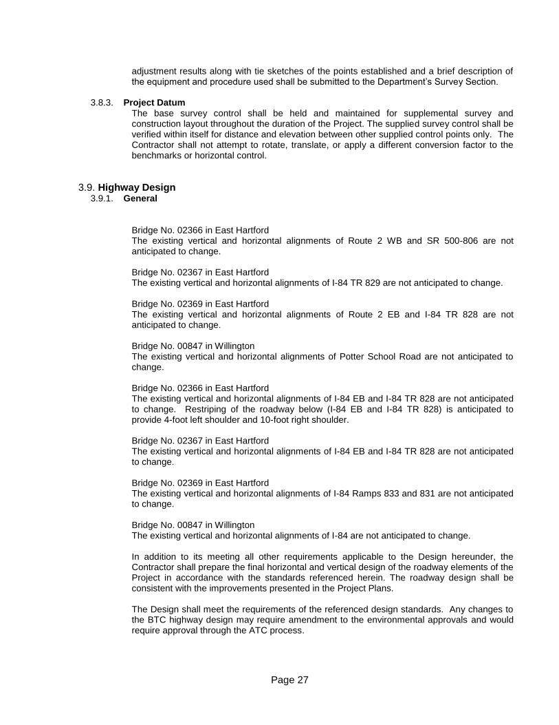
Page 27
adjustment results along with tie sketches of the points established and a brief description of the equipment and procedure used shall be submitted to the Department’s Survey Section.
3.8.3. Project Datum
The base survey control shall be held and maintained for supplemental survey and construction layout throughout the duration of the Project. The supplied survey control shall be verified within itself for distance and elevation between other supplied control points only. The Contractor shall not attempt to rotate, translate, or apply a different conversion factor to the benchmarks or horizontal control.
3.9. Highway Design 3.9.1. General
Bridge No. 02366 in East Hartford The existing vertical and horizontal alignments of Route 2 WB and SR 500-806 are not anticipated to change. Bridge No. 02367 in East Hartford The existing vertical and horizontal alignments of I-84 TR 829 are not anticipated to change. Bridge No. 02369 in East Hartford The existing vertical and horizontal alignments of Route 2 EB and I-84 TR 828 are not anticipated to change. Bridge No. 00847 in Willington The existing vertical and horizontal alignments of Potter School Road are not anticipated to change. Bridge No. 02366 in East Hartford The existing vertical and horizontal alignments of I-84 EB and I-84 TR 828 are not anticipated to change. Restriping of the roadway below (I-84 EB and I-84 TR 828) is anticipated to provide 4-foot left shoulder and 10-foot right shoulder.
Bridge No. 02367 in East Hartford The existing vertical and horizontal alignments of I-84 EB and I-84 TR 828 are not anticipated to change. Bridge No. 02369 in East Hartford The existing vertical and horizontal alignments of I-84 Ramps 833 and 831 are not anticipated to change. Bridge No. 00847 in Willington The existing vertical and horizontal alignments of I-84 are not anticipated to change. In addition to its meeting all other requirements applicable to the Design hereunder, the Contractor shall prepare the final horizontal and vertical design of the roadway elements of the Project in accordance with the standards referenced herein. The roadway design shall be consistent with the improvements presented in the Project Plans. The Design shall meet the requirements of the referenced design standards. Any changes to the BTC highway design may require amendment to the environmental approvals and would require approval through the ATC process.

Page 28
The Department will not accept any ATC that reduces the final number of lanes on any roadway as shown in the BTC. Design Exceptions have previously been approved and are listed in Section [3.4.3.1].
3.9.2. Roadway Design Criteria
The following sections contain design criteria for the various roadways in the Project. These criteria shall be used for the design of the roadways pending Design Approval.
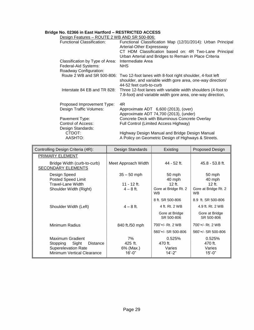
Page 29
Bridge No. 02366 in East Hartford – RESTRICTED ACCESS Design Features – ROUTE 2 WB AND SR 500-806: Functional Classification: Functional Classification Map (12/31/2014): Urban Principal
Arterial-Other Expressway CT HDM Classification based on: 4R Two-Lane Principal Urban Arterial and Bridges to Remain in Place Criteria
Classification by Type of Area: Intermediate Area Federal-Aid Systems: NHS Roadway Configuration: Route 2 WB and SR 500-806: Two 12-foot lanes with 8-foot right shoulder, 4-foot left
shoulder, and variable width gore area, one-way direction/ 44-52 feet curb-to-curb
Interstate 84 EB and TR 828: Three 12-foot lanes with variable width shoulders (4-foot to 7.8-foot) and variable width gore area, one-way direction,
Proposed Improvement Type: 4R Design Traffic Volumes: Approximate ADT 6,600 (2013), (over) Approximate ADT 74,700 (2013), (under) Pavement Type: Concrete Deck with Bituminous Concrete Overlay Control of Access: Full Control (Limited Access Highway) Design Standards: CTDOT: Highway Design Manual and Bridge Design Manual
AASHTO: A Policy on Geometric Design of Highways & Streets.
Controlling Design Criteria (4R): Design Standards Existing Proposed Design
PRIMARY ELEMENT
Bridge Width (curb-to-curb) Meet Approach Width 44 - 52 ft. 45.8 - 53.8 ft. SECONDARY ELEMENTS
Design Speed 35 – 50 mph 50 mph 50 mph Posted Speed Limit
40 mph 40 mph Travel-Lane Width 11 - 12 ft. 12 ft. 12 ft. Shoulder Width (Right) 4 – 8 ft. Gore at Bridge Rt. 2
WB
8 ft. SR 500-806
Gore at Bridge Rt. 2 WB
8.9 ft. SR 500-806
Shoulder Width (Left) 4 – 8 ft. 4 ft. Rt. 2 WB
Gore at Bridge SR 500-806
4.9 ft. Rt. 2 WB
Gore at Bridge SR 500-806
Minimum Radius 840 ft./50 mph 700’+/- Rt. 2 WB
560’+/- SR 500-806
700’+/- Rt. 2 WB
560’+/- SR 500-806
Maximum Gradient 7% 0.525% 0.525% Stopping Sight Distance (min.)
425 ft. 470 ft. 470 ft. Superelevation Rate 6% (Max.) Varies Varies Minimum Vertical Clearance 16’-0”
14’-2”
15’-0”
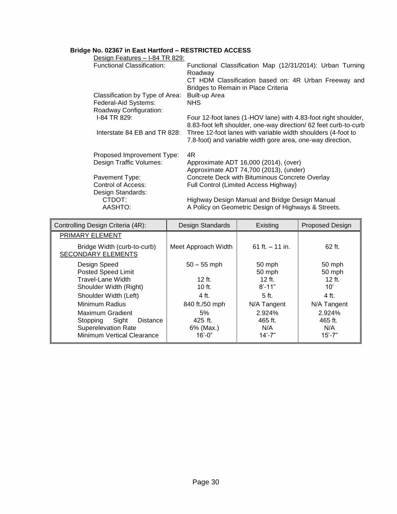
Page 30
Bridge No. 02367 in East Hartford – RESTRICTED ACCESS Design Features – I-84 TR 829: Functional Classification: Functional Classification Map (12/31/2014): Urban Turning
Roadway CT HDM Classification based on: 4R Urban Freeway and Bridges to Remain in Place Criteria
Classification by Type of Area: Built-up Area Federal-Aid Systems: NHS Roadway Configuration: I-84 TR 829: Four 12-foot lanes (1-HOV lane) with 4.83-foot right shoulder,
8.83-foot left shoulder, one-way direction/ 62 feet curb-to-curb Interstate 84 EB and TR 828: Three 12-foot lanes with variable width shoulders (4-foot to
7.8-foot) and variable width gore area, one-way direction, Proposed Improvement Type: 4R Design Traffic Volumes: Approximate ADT 16,000 (2014), (over) Approximate ADT 74,700 (2013), (under) Pavement Type: Concrete Deck with Bituminous Concrete Overlay Control of Access: Full Control (Limited Access Highway) Design Standards: CTDOT: Highway Design Manual and Bridge Design Manual
AASHTO: A Policy on Geometric Design of Highways & Streets.
Controlling Design Criteria (4R): Design Standards Existing Proposed Design
PRIMARY ELEMENT
Bridge Width (curb-to-curb) Meet Approach Width 61 ft. – 11 in. 62 ft. SECONDARY ELEMENTS
Design Speed 50 – 55 mph 50 mph 50 mph Posted Speed Limit
50 mph 50 mph Travel-Lane Width 12 ft. 12 ft. 12 ft. Shoulder Width (Right) 10 ft. 8’-11” 10’
Shoulder Width (Left) 4 ft. 5 ft. 4 ft.
Minimum Radius 840 ft./50 mph N/A Tangent N/A Tangent
Maximum Gradient 5% 2.924% 2.924% Stopping Sight Distance (min.)
425 ft. 465 ft. 465 ft. Superelevation Rate 6% (Max.) N/A N/A Minimum Vertical Clearance 16’-0”
14’-7”
15’-7”
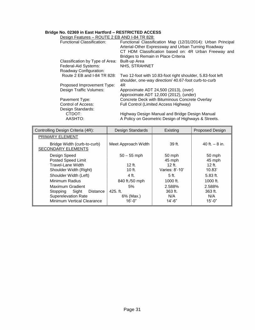
Page 31
Bridge No. 02369 in East Hartford – RESTRICTED ACCESS Design Features – ROUTE 2 EB AND I-84 TR 828: Functional Classification: Functional Classification Map (12/31/2014): Urban Principal
Arterial-Other Expressway and Urban Turning Roadway CT HDM Classification based on: 4R Urban Freeway and Bridges to Remain in Place Criteria
Classification by Type of Area: Built-up Area Federal-Aid Systems: NHS, STRAHNET Roadway Configuration: Route 2 EB and I-84 TR 828: Two 12-foot with 10.83-foot right shoulder, 5.83-foot left
shoulder, one-way direction/ 40.67-foot curb-to-curb Proposed Improvement Type: 4R Design Traffic Volumes: Approximate ADT 24,500 (2013), (over) Approximate ADT 12,000 (2012), (under) Pavement Type: Concrete Deck with Bituminous Concrete Overlay Control of Access: Full Control (Limited Access Highway) Design Standards: CTDOT: Highway Design Manual and Bridge Design Manual
AASHTO: A Policy on Geometric Design of Highways & Streets.
Controlling Design Criteria (4R): Design Standards Existing Proposed Design
PRIMARY ELEMENT
Bridge Width (curb-to-curb) Meet Approach Width 39 ft. 40 ft. – 8 in. SECONDARY ELEMENTS
Design Speed 50 – 55 mph 50 mph 50 mph Posted Speed Limit
45 mph 45 mph Travel-Lane Width 12 ft. 12 ft. 12 ft. Shoulder Width (Right) 10 ft. Varies: 8’-10’ 10.83’
Shoulder Width (Left) 4 ft. 5 ft. 5.83 ft.
Minimum Radius 840 ft./50 mph 1000 ft. 1000 ft.
Maximum Gradient 5% 2.588% 2.588% Stopping Sight Distance (min.)
425. ft. 363 ft. 363 ft. Superelevation Rate 6% (Max.) N/A N/A Minimum Vertical Clearance 16’-0”
14’-6”
15’-0”
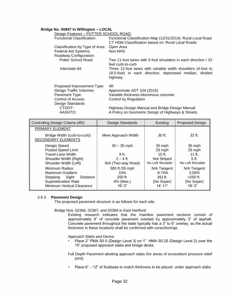
Page 32
Bridge No. 00847 in Willington – LOCAL Design Features – POTTER SCHOOL ROAD: Functional Classification: Functional Classification Map (12/31/2014): Rural Local Road
CT HDM Classification based on: Rural Local Roads Classification by Type of Area: Open Area Federal-Aid Systems: Non-NHS Roadway Configuration:
Potter School Road: Two 11-foot lanes with 5-foot shoulders in each direction / 32 feet curb-to-curb
Interstate 84: Three 12-foot lanes with variable width shoulders (4-foot to 18.5-foot) in each direction, depressed median, divided highway
Proposed Improvement Type: 4R Design Traffic Volumes: Approximate ADT 104 (2016) Pavement Type: Variable thickness bituminous concrete Control of Access: Control by Regulation Design Standards: CTDOT: Highway Design Manual and Bridge Design Manual
AASHTO: A Policy on Geometric Design of Highways & Streets.
Controlling Design Criteria (4R): Design Standards Existing Proposed Design
PRIMARY ELEMENT
Bridge Width (curb-to-curb) Meet Approach Width AApproach Width
30 ft. 32 ft. SECONDARY ELEMENTS
Design Speed 30 – 35 mph 35 mph 35 mph Posted Speed Limit
25 mph 25 mph Travel-Lane Width 9 ft. 15 ft. 11 ft. Shoulder Width (Right) 2 – 4 ft. Not Striped 5 ft. Shoulder Width (Left) N/A (Two-way Road) No Left Shoulder No Left Shoulder
Minimum Radius 385 ft./35 mph N/A Tangent N/A Tangent Maximum Gradient 10% -9.74% 3.00% Stopping Sight Distance (min.)
250 ft. 261 ft. >250 ft. Superelevation Rate 6% (Max.) (No Super) (No Super) Minimum Vertical Clearance 16’-3”
14’-11”
16’-3”
3.9.3. Pavement Design
The proposed pavement structure is as follows for each site: Bridge Nos. 02366, 02367, and 02369 in East Hartford:
Existing research indicates that the mainline pavement sections consist of approximately 9” of concrete pavement overlaid by approximately 3” of asphalt. Concrete pavement throughout the state typically has a 3” to 6” overlay, so the actual thickness in these locations shall be confirmed with cores/borings. Approach Slabs and Decks: • Place 2” PMA S0.5 (Design Level 3) on 1” HMA S0.25 (Design Level 2) over the
15” proposed approach slabs and bridge decks Full Depth Pavement abutting approach slabs (for areas of excavation/ pressure relief
joint): • Place 6” – 12” of Subbase to match thickness to be placed under approach slabs
Page 33
• Place 9” of PMA S1.0 (Design Level 3) in two equal 4.5” lifts to match the Portland cement concrete pavement on the roadway
• Next, depending on the thickness of the bituminous over the mainline concrete pavement, place one of the following combinations to match existing elevation of the roadway ( again thickness to be confirmed with borings/cores):
o 2” PMA S0.5 (Design Level 3) on 1” HMA S0.25 (Design Level 2) to make up
3 inches o 2.5” S0.5 (Design Level 3) on 1” HMA S0.25 (Design Level 2) to make up 3.5
inches o 2” S0.5 (Design Level 3) on 2” S0.5 (Design Level 3) to make up 4 inches o 2.25” S0.5 (Design Level 3) on 2.25” S0.5 (Design Level 3) to make up 4.5
inches o 2.5” S0.5 (Design Level 3) on 2.5” S0.5 (Design Level3) to make up 5 inches o 2.25” S0.5 (Design Level 3) on 2.25” S0.5 (Design Level 3) on 1” HMA S0.25
(Design Level 2) to make up 5.5 inches o 2” S0.5 (Design Level 3) on 2” S0.5 (Design Level3) on 2” S0.5 (Design Level
3) to make up 6 inches These full depth pavement sections should extend from curb to curb and be a minimum of 10 feet long. The excavation to remove the approach slab may also require removal of some portion of the mainline concrete slabs for 02366, 02367 and 02369. If partial removal of concrete pavement slabs is necessary, no slab should be reduced by more than 50% of the current length. If removal of more than 50% of the slab is needed the entire slab should be removed and the full depth flexible pavement section should be extended back to the next concrete pavement joint. . No changes to the pavement structure are allowed, and no subsequent design for pavement structure by the Contractor is required.] For the East Hartford sites, borings shall be obtained within the shoulders and gore areas if they are intended to have traffic during construction staging. An adequate number of borings and data shall be collected to determine whether the shoulder and gore areas are suitable for traffic loading. If the pavement structure is inadequate, the MPT Plans shall include staging to upgrade the pavement structure prior to traffic loads within the shoulder and gore areas. The scheduling of the borings, boring data, and MPT for the boring operation shall be the inclusive in this item. Any costs associated with taking the borings including temporary traffic control, determining the suitability, design of any improvements required, constructing improvements, and any final restoration of the areas shall be included in the proposal. See Traffic Engineering section for additional information on pavement design required for temporary traffic conditions. Bridge No. 00847 in Willington:
Records indicate that this section is a flexible pavement leading up to the bridge.
Full Depth Pavement abutting approach slabs (for areas of excavation):
• Place 4” of HMA S0.5 (Design Level 2) on 4” of HMA S1.0 (Design Level 2) on 12” of Subbase
3.9.4. Pavement Patching The Contractor is responsible for maintenance of the existing pavement throughout the duration of construction. For Bridge Nos. 02366, 02367, and 02369 East Hartford, 350 square yards are estimated for pavement patches. All patches must be approved by Department
Page 34
before the repairs may be made. The cost of pavement patching shall be included in the Lump Sum Cost for the Project. Patching in excess of this quantity will be considered extra work.
3.9.5. Potential Alternatives
ATC’s that provide a different pavement structure than that specified in the BTC will not be allowed.
3.10. Traffic Engineering 3.10.1. General
The Contractor is responsible for the final design of all traffic engineering aspects of the Project.
3.10.2. Maintenance and Protection of Traffic Plan
The MPT concepts presented in the RFP have been coordinated closely with affected agencies including the Town of Willington, the Town of East Hartford, East Hartford Fire Department, East Hartford Police Department and emergency services serving the area. If an ATC changes these MPT concepts and Stages, the Contractor will be responsible for obtaining required approvals of said changes from affected third parties with relevant authority. The construction staging sequence and MPT concepts may be revised if approved by the Department. The various lane configurations and roadway closures, detours and temporary access roads shall be followed as shown in the staging plans unless a modification of same has been accepted by the Department through the ATC process. Changes to the number of traffic lanes shown in the staging plans will not be allowed. Each bridge construction project and their associated detours described below will be conducted separately during different construction seasons.
Bridges No. 02366/02367 Bridge No. 02367 carries traffic from I-84 Westbound Exit 54 and the I-84 Westbound High-Occupancy Vehicle (HOV) lane to the Founders Bridge and downtown Hartford over I-84 Eastbound and Exit 55 – Route 2 Eastbound. Bridge No. 02366 carries traffic from Route 2 Westbound to the Founders Bridge and downtown Hartford and traffic from Governor Street over I-84 Eastbound and Exit 55 – Route 2 Eastbound. The proposed project would maintain two (2) of the current three (3) lanes of traffic on Bridge No. 02367 but would completely close Bridge No. 02366. In order to accommodate the closure on Bridge No. 02366, traffic from Route 2 Westbound will be detoured to Route 2 Westbound Exit 3 – Pitkin Street, turning left at the bottom of ramp. Traffic would continue westbound on Pitkin Street, through the Jayce Street intersection to Darlin Street where it would turn right. Traffic would then turn left onto the Route 2 Westbound on-ramp to the Founders Bridge and downtown Hartford. Traffic from Governor Street destined for the Founders Bridge and downtown Hartford will be directed to Thomas Street, across Connecticut Boulevard onto Ash Street to East River Drive. Traffic would then turn left onto Darlin Street and then right onto the Route 2 Westbound on-ramp to the Founders Bridge. To accommodate the traffic detour, the Pitkin Street off-ramp will be changed to provide a left- and left-plus-right turn lane on the ramp. Westbound Pitkin Street will be restriped to provide two lanes of travel from the ramp, through the Jayce Street
Page 35
intersection to Darlin Street where the right lane will drop as a right-turn only lane. Traffic signals at the ramp, Jayce Street and Darlin Street may need to be retimed to better facilitate the movement of traffic along the detour route. Bridge No. 02369 Bridge No. 02369 carries Route 2 Eastbound over the ramp connecting the Founders Bridge and downtown Hartford to I-84 Eastbound. Traffic on the bridge comes from two (2) ramps: one from the Founders Bridge and downtown Hartford and the other from I-84 Eastbound destined for Route 2 Eastbound. During reconstruction of this bridge, only one lane of traffic will be allowed over the bridge which necessitates the closing of the ramp from the Founders Bridge and downtown Hartford. In order to accommodate this closure, traffic from the Founders Bridge and downtown Hartford destined for Route 2 Eastbound will be diverted off the highway at Exit 3 – Pitkin Street, turning left at the bottom of the ramp, through the Darlin Street intersection, to a right-turn on Jayce Street. Traffic would then follow Jayce Street south directly to the Route 2 Eastbound on-ramp at East River Drive. In order to facilitate the flow of traffic along the Founders Bridge detour route, a series of local street improvements are being proposed. The Exit 3 off-ramp will be widened to accommodate two lanes of traffic to provide a left- and left-plus-right turn lane on the ramp. Eastbound Pitkin Street from the ramp to Jayce Street will be restriped to provide two lanes of traffic (at Jayce Street the right lane will drop as a right-turn only lane) and traffic signals at the ramp, Darlin Street and Jayce Street may need to be retimed to better facilitate the movement of traffic along the detour route. Bridge No. 00847 Bridge No. 00847 carries Potter School Road over I-84 Eastbound and Westbound in Willington, Connecticut. It connects Mihaliak Road to the north with Balazs Road to the south and is part of a network of low volume local roads serving low-density residential properties in the area. It is one of only three crossings along the 5.9 miles of I-84 in Willington. The Average Daily Traffic (ADT) for Potter School Road has been estimated to be 400 vehicles per day. In order to minimize the length of time to reconstruct Bridge No. 00847, the state is proposing to temporarily close the road to through traffic on Potter School Road and detour vehicles to the crossing at Rudy Road (State Route 320) to the west. The detour for southbound traffic will begin at the Mihaliak Road intersection where traffic would be detoured by turning right onto Old County Road into the Town of Stafford. Old County Road turns back into Mihaliak Road in Willington until the I-84 Westbound ramps where it changes to Ruby Road ((State Route 320). Traffic would then cross over I-84 on Ruby Road, turn left onto Turnpike Road and follow it until it gets to Balazs Road where traffic can turn left to get back to Potter School Road south of I-84, right onto Fermer Road or continue on Turnpike Road to their destination.
The detour for Potter School Road northbound traffic would begin at the intersection of Balazs Road/Fermer Road and Turnpike Road where traffic will be advised of the Potter School Road bridge closure at I-84. Traffic would be directed to go west onto Turnpike Road and follow it to Rudy Road (State Route 320). Traffic will then turn right onto Ruby Road (State Route 320), following it over I-84 past the I-84 Southbound ramps where it turns into Mihaliak Road. Traffic would follow Mihaliak Road into the Town of Stafford where the road turns into Old County Road. Traffic would follow Old County Road to the intersection of Potter School Road and Mihaliak
Page 36
Road where it can turn right onto the northern section of Potter School Road or left to continue on Mihaliak Road back into Stafford.
Pedestrian facilities including ADA compliance shall be maintained wherever pedestrian travel is currently permitted on all open roads. The Contractor is not responsible for maintaining pedestrian travel on closed roadways. The Contractor will be responsible for maintenance and providing an acceptable operating condition of the travel lanes within the Site. Any proposed changes to the requirements of this section are considered to be Alternative Technical Concept (ATC) and must be submitted for pre-approval before incorporation into the Technical Proposal. Current traffic movements through intersections in the surrounding Project area shall be modified to accommodate traffic detours during construction. The Contractor shall facilitate the necessary detours and maintenance of intersections, including early notifications to the stakeholders of upcoming road closures and detours. For the East Hartford sites, any shoulders and gore areas intended to have traffic during construction staging will require the Contractor to provide a determination to the Department as to whether the shoulder and gore areas are suitable for traffic loading. Refer to Highway Design section above for additional requirements related to these investigations, design and construction. A detailed MPT Plan is required for all major construction elements. Plans shall be drawn to scale and include all proposed traffic control devices, signing and pavement markings. Traffic management of all bicycle, pedestrian, and vehicular traffic must be maintained within the limits of work throughout construction. The Contractor shall provide traffic mitigation plans as needed for the intersections within the proposed detour routes. The MPT Plan shall depict the intended staging and lane requirements during construction. The requirements of the MPT plan include:
Vehicular, bicycle and pedestrian access to local businesses and tourist attractions is at all times during construction. The use of the detours shown in the BTC for this purpose is acceptable.
A minimum of 11-foot wide vehicle travel lane[s] and 1-foot wide shoulders on [Road Name] during construction.
Traffic signal monitoring, with the potential for traffic signal timing changes at the locations defined in this RFP. Monitoring of signal timings, suggested changes, and implementation shall be coordinated and implemented by the Contractor. The Contractor shall coordinate all work with the Department and obtain approval from the Department prior to implementation.
Implementation of detours specified above as necessary. If an alternate route is considered, a plan shall be prepared by the Contractor and approved by the Department, the Town of Willington and the Town of East Hartford prior to implementation. Such a plan would be considered an ATC.
Police detail or officers as required. Certified flaggers may also be used if the traffic volume and conditions meet the Department, the Town of Willington and the Town of East Hartford criteria for flaggers. The Contractor shall coordinate this effort with the Department.
Access during Construction Access to local businesses and residences in the Project area must be maintained during construction. Temporary closures and detailed construction sequencing must allow traffic to be maintained during the construction of the project. The Contractor will be responsible for maintenance of traffic and providing
Page 37
an acceptable operating condition of the travel lanes within the Project area. The Contractor shall facilitate the detours and maintenance of intersection operations.
The Contractor will be required to maintain access (vehicles, bicycles, and pedestrians) to adjacent businesses and recreational facilities at all times during construction. For Bridge No. 00847 in Willington, access to the west side of the bridge is via Old County Road or Michalec Road in Stafford. These existing rural local roads are narrow and partially paved. The Contractor is responsible for radio transmission during construction equipment and large material deliveries. If construction equipment or large material deliveries are sent up Mihaliak Road/Old County Road, a flagger with radios should be stationed at the intersection of Mihaliak Road and Mihaliak Road Extension or the driveway just south of the Willington/Stafford town line and the intersection of Potter School Road and Old County Road. The exact locations will depend upon the size of the equipment and maneuverability to allow safe passage of construction equipment, material deliveries, and other vehicles utilizing the town roads. It is the Contractor’s responsibility to fully investigate the existing roads for construction access.
Access to all work zones shall be detailed in the Maintenance and Protection of Traffic Plans.
Temporary Roadside Elements All temporary roadside design elements including but not limited to highway guiderails, construction barriers, sign supports, and drainage outlets shall be designed in accordance with the most current AASHTO Roadside Design Guide and the AASHTO Manual for Assessing Safety Hardware ("MASH"). The structural design of all temporary roadside elements including all components, support poles, appurtenances, and anchorages shall be designed in accordance with the AASHTO Standard Specifications for Structural Supports for Highway Signs, Luminaires, and Traffic Signals. The sign supports shall be designed without the assistance of any guying wires or external supports. Proposed signing plans shall include the layouts showing locations of existing and proposed ground mounted and overhead signs, special sign details, legend, sign lighting and structural and foundation requirements. Any required electric service shall be provided by the Contractor in coordination with the local electric utility. The Contractor will be responsible for the maintenance of all temporary roadside elements and the resolution of any found to be impeding safe operation of traffic, subject to the oversight and discretion of the Department.
Temporary Pavement Markings
The Contractor will provide temporary pavement markings as required within the Project limits to provide a complete traffic pattern at all times during the Project. The Contractor will be required to design and install pavement markings in accordance with Department and MUTCD work zone standards and specifications. All lane configurations during all stages of construction shall be delineated with temporary pavement markings. Temporary lane configurations on other roadways that will remain in place for more than thirty-six (36) hours shall be delineated with temporary pavement markings. Two options for temporary pavement markings are allowed: 1. Use of Temporary Plastic Pavement Marking Tape:
Page 38
Under this option, the Contractor shall cover all temporary and existing conflicting pavement markings with black temporary plastic pavement tape. Removal of temporary plastic pavement markings through the use of grinding will not be allowed. The temporary plastic tape pavement marking shall be maintained for the duration of the Project.
2. Hot-Applied Paint Pavement Markings: Under this option, the contractor shall grind off all temporary and existing conflicting pavement markings during all stages of construction. Black temporary plastic pavement tape may be used in lieu of grinding. At the completion of staged construction, all pavement areas that were affected by grinding of markings shall be milled to a minimum depth of 2” and replaced with new pavement that matches the specified pavement in the vicinity of the bridges. Other non-destructive methods for removal in lieu of grinding off existing or temporary pavement markings and repaving may be proposed through the ATC process. Upon completion of this work, all previous markings shall be re-established with permanent pavement markings according to the project specifications.
Regardless of the option chosen, the Contractor shall promptly respond to all requests by the Department to refresh or remove markings within the Project limits during the construction period. The pavement markings on Pitkin Street in East Hartford are currently designed to accommodate two lanes of traffic in the westbound direction and one lane of traffic in the eastbound direction. Pitkin Street will require a change of pavement markings from the existing conditions in order to accommodate the detour of traffic associated with the superstructure replacement of Bridge No. 02369, which shall provide for two lanes of traffic in the eastbound direction and one lane of traffic in the westbound direction. Pitkin Street will require a subsequent change of pavement markings to accommodate the subsequent detour of traffic associated with the superstructure replacement of Bridge No. 02366. All temporary pavement markings on Pitkin Street shall be painted pavement markings. The Contractor shall provide permanent pavement markings on Pitkin Street at the completion of the project. Pavement marking plans have been provided by the Town of East Hartford for Pitkin Street. The Contractor shall prepare a final design for pavement markings on Pitkin Street as part of the final roadway design on this project.
Temporary Barrier
The Contractor shall provide TPCBC as shown on the MPT plans. Movable precast concrete barrier may be substituted for standard TPCBC. The type of movable barrier proposed shall be submitted for approval by the Department.
Off-Site Traffic Signals
The Contractor is expected to alleviate increased delays and queues that may occur at intersections near the Site. The intersections likely to be so affected are shown on the Contractor’s Construction Staging and Detour Plans The Construction Staging and Detour Plan for Bridges 02366 and 02369 traffic propose to detour traffic onto Pitkin Street, Darlin Street and Jayce Street in East Hartford. The detours associated with these bridge closings and reconstruction will require the modification of pavement markings and traffic signal timings along the detour routes. For the Bridge 02366 project, three signals on Pitkin Street (Pitkin Street at Route 2 WB Exit Ramp No.3; Pitkin Street at Jayce Street and Pitkin Street at Darlin Street) may require modifications to signal timings. For
Page 39
Bridge 02369, signal timing revisions at four intersections (Pitkin Street at Founders Bridge EB Exit 3; Pitkin Street at Darlin Street, Pitkin Street at Jayce Street and Jayce Street at East River Drive) may be required Traffic volumes are included in the Appendix. If additional traffic counts are required for the final design due to an ATC proposed by the Contractor, the Contractor shall obtain them at no cost to the Department. Prior to detouring traffic, the Contractor shall submit to the Department for approval, temporary signalization plans with revised timings based on capacity analysis using the latest version of Synchro Software. The Contractor is expected to have a Monitoring Plan in place and make controlling-signal-timing changes to accommodate the changes in the traffic patterns. The Monitoring Plan must be prepared by the Contractor and submitted for approval to the Department and the Towns of Willington and East Hartford before the commencement of construction activities that may delay or disrupt AM or PM peak-period traffic. The Monitoring Plan must include proposed staffing by the Contractor for all identified intersections during each peak traffic period during all stages of construction. The Plan shall define the methodology to be used to react to traffic problems identified during the monitoring. All signal timing changes must be approved by the Department, and if approved will then be implemented by the Contractor.
Transportation Management Plan (TMP)
[Insert and edit the following section if a TMP is required for the project] The need for a Transportation Management Plan ("TMP") has been evaluated by the Department and it has been determined that the development of a TMP is required for this Project. The Contractor is required to submit a TMP to the Department in accordance with the FHWA guidance document titled “Developing and Implementing Transportation Management Plans for Work Zones.” This document can be found on the FHWA website at http://www.ops.fhwa.dot.gov/wz/resources/publications/trans_mgmt_plans/index.htm. Documentation of the TMP pertinent to the Project Design shall be included in the Design Report which is required with the standard milestone submissions. Elements of the TMP shall be presented in the Contract plans (such as the Temporary Traffic Control Plan(s)) and specifications. In addition to the project specific Traffic Management Plan, there is also a Regional Transportation Management Plan currently under development. Due to the number of state and local construction contracts being let between the spring of 2017 and fall of 2019, a Regional Traffic Management Plan is being prepared with the intent to coordinate traffic impacts across all active projects in the Greater Hartford area. The Regional TMP will ensure that lane shifts/closures on I-84, periodic ramp closures, and the local road detours associated with this project and other projects in close proximity are well coordinated with other ongoing state and municipal projects along the I-84, I-91, Rte. 2, Rte. 15 corridors and major state and local streets.
Be aware, the Regional TMP coordination efforts ongoing may require adjustment to the planned timing of specific maintenance and protection of traffic activities (lane closures and ramp closings) on this project.
Temporary Changeable Message Signs
Page 40
The Contractor shall provide temporary changeable message signs outside of the immediate construction area in order to provide advance warnings to motorists. The Contractor shall work with the Department to finalize the changeable message sign locations and text. Such signs shall not be placed on private property or on sidewalks. The Contractor should be aware that multiple construction projects are planned in the immediate vicinity of the Project. It shall be the responsibility of the Contractor to work with contractors on those adjacent projects and determine a common plan of advance warning and changeable message signs that works for all stages of construction. The Contractor will be responsible for supplying and maintaining the temporary changeable message signs. The Contractor will promptly respond to all Department requests to relocate or update text on the changeable message signs during the Project.
3.10.3. Permanent Roadside Elements
All permanent roadside design elements, including, but not limited to highway guiderail, vehicle barriers, sign supports, drainage outlets, railings, curbs, light poles, gates, and fences shall be designed in accordance with the most current AASHTO Roadside Design Guide and the MASH. All permanent roadside design elements, including, but not limited to highway guiderail, vehicle barriers, sign supports, drainage outlets, railings, curbs, light poles, gates, and fences shall be maintained and protected during construction. Any damage to these elements or equipment shall be repaired or replaced in kind at no cost to the Department.
3.10.4. Permanent Pavement Markings
The Contractor shall provide permanent pavement markings as required within the Project limits as necessary for the proper prosecution of the Project. The Contractor must design and install pavement markings in accordance with Department and MUTCD standards and specifications.
3.11. Geotechnical 3.11.1. General
Geotechnical engineering has not been completed for the BTC by the Department. Geotechnical engineering will be required by the Contractor for the bridge substructures in the final design. The BTC is based on the reuse of the existing substructures and footings including the strengthening shown in the BTC plans. The BTC includes strengthening by means of infilling all portions of the piers above the footings, and is based on the superstructure replacements shown in the BTC plans. Any change to the BTC that, in the Department’s opinion, affects the geotechnical design will constitute an ATC. In that case, the Contractor will be responsible for all supplemental geotechnical explorations, testing, research, and other measures necessary to support the ATC.
3.11.2. Investigations No Geotechnical report for the BTC has been included in RFP. The results of a subsurface exploration program, along with historical information, is provided in Appendix B The Contractor shall be responsible for assessing this information, retaining a geotechnical engineer and preparing a Geotechnical Report in support of the final design. All geotechnical construction shall be conducted in accordance with the geotechnical reports prepared as part

Page 41
of the Final Design. Any additional subsurface explorations required to complete the Geotechnical report shall be the responsibility of the Contractor.
3.11.3. Existing Geotechnical Information
Subsurface geotechnical investigations have been performed for the development of the BTC, to supplement the original boring information and other historical information. Archive boring and foundation information from the drawing sets for the existing bridges and other sources are included in Appendix B.
3.11.4. Geotechnical Study by the Contractor
As indicated above, geotechnical study and analysis by the Contractor will be necessary for completion of the final design and preparation of the Geotechnical Report. This work shall be included in the proposal price. Additional geotechnical explorations and analyses, if required, shall be performed in accordance with the Department’s Geotechnical Engineering Manual, and any relevant Consulting Engineering Memoranda. This additional work shall also be included in the proposal price. The Geotechnical Report shall be submitted with the Semi-Final Design submittal. The Contractor shall meet all requirements and obtain all governmental approvals necessary for geotechnical explorations, including “Call before You Dig” requirements, and all approvals and permits required for access road grading, drilling, and groundwater protection from inter-aquifer contamination. All rock samples shall be delivered for review by the Department to a location agreed upon by the Department.
Page 42
3.11.5. Geotechnical Reports
No Geotechnical reports are provided in this RFP. Geotechnical reports will need to be prepared as part of the final design .
3.11.6. Bridge Substructures
The Contractor will be required to provide confirmation that the rehabilitated substructures are adequate for the proposed construction under the final design provided by the Contractor. The stability and capacity investigations by the Contractor for the foundations as part of the final design shall include all construction activities, construction staging, groundwater table, final ground surface, and temporary and final load condition on the foundations. The Contractor shall demonstrate that the proposed revised designs meet both strength and serviceability requirements of the latest Department’s Bridge Design Manual and the applicable Geotechnical Memorandum and Reports.
Bridge No. 02366
The existing Bridge No. 02366 is a three span bridge consisting of a cast-in-place concrete deck made composite with steel girders that carries [Road Name] over [Road or Spanned Feature(s)]. The superstructure is supported on two cast-in-place concrete abutments and two cast-in-place concrete piers, all of which are supported on spread footings. The BTC includes normal substructure repairs as required to address any deficiencies including concrete patching and crack sealing. Work also includes strengthening by means of infilling between the undersides of the pier cap and the top of footing as shown in the BTC plans. Strengthening of the piers is required to address anticipated substandard structural capacity and load rating of the piers after construction of the replacement superstructure. The Contractor shall implement a monitoring program that shall measure vertical and lateral movement of the substructures during construction. The monitoring program may consist of survey benchmarks logged on a daily basis during the stage construction of the bridges. Any movement noted during construction shall be reported to the Department immediately. The Department will determine if any remedial action is required. The cost of remedial actions will be assumed by the responsible party.
Bridge No. 02367
The existing Bridge No. 02367 is a three span bridge consisting of a cast-in-place concrete deck made composite with steel girders that carries [Road Name] over [Road or Spanned Feature(s)]. The superstructure is supported on two cast-in-place concrete abutments and two cast-in-place concrete piers, all of which are supported on spread footings. The BTC includes normal substructure repairs as required to address any deficiencies including concrete patching and crack sealing. Work also includes strengthening by means of infilling between the undersides of the pier cap and the top of footing as shown in the BTC plans.
Page 43
Strengthening of the piers is required to address structural capacity and load rating of the piers after construction of the replacement superstructure. Preliminary rating calculations show the pier components to have a substandard rating after construction of the new superstructure under the latest AASHTO code requirements. The Contractor shall implement a monitoring program that shall measure vertical and lateral movement of the substructures during construction. The monitoring program may consist of survey benchmarks logged on a daily basis during the stage construction of the bridges. Any movement noted during construction shall be reported to the Department immediately. The Department will determine if any remedial action is required. The cost of remedial actions will be assumed by the responsible party.
Bridge No. 02369 The existing Bridge No. 02369 is a three span bridge consisting of a cast-in-place concrete deck made composite with steel girders that carries [Road Name] over [Road or Spanned Feature(s)]. The superstructure is supported on two cast-in-place concrete abutments and two cast-in-place concrete piers, all of which are supported on spread footings. The BTC includes normal substructure repairs as required to address any deficiencies including concrete patching and crack sealing. Work also includes strengthening by means of infilling between the undersides of the pier cap and the top of footing as shown in the BTC plans. Strengthening of the piers is required to address structural capacity and load rating of the piers after construction of the replacement superstructure. Preliminary rating calculations show the pier components to have a substandard rating after construction of the new superstructure under the latest AASHTO code requirements. The Contractor shall implement a monitoring program that shall measure vertical and lateral movement of the substructures during construction. The monitoring program may consist of survey benchmarks logged on a daily basis during the stage construction of the bridges. Any movement noted during construction shall be reported to the Department immediately. The Department will determine if any remedial action is required. The cost of remedial actions will be assumed by the responsible party.
Bridge No. 00847 The existing Bridge No. 00847 is a two span bridge consisting of a cast-in-place concrete deck made composite with steel girders that carries Potter School Road over I-84. The superstructure is supported on two cast-in-place concrete abutments and a single cast-in-place concrete pier, all of which are supported on spread footings. The BTC includes normal substructure repairs as required to address any deficiencies including concrete patching and crack sealing. Work also includes strengthening by means of infilling between the undersides of the pier cap and the top of footing as shown in the BTC plans.
Page 44
Strengthening of the pier is required to address structural capacity and load rating of the piers after construction of the replacement superstructure. Preliminary rating calculations show the pier components to have a substandard rating after construction of the new superstructure under the latest AASHTO code requirements. The Contractor shall implement a monitoring program that shall measure vertical and lateral movement of the substructures during construction. The monitoring program may consist of survey benchmarks logged on a daily basis during the stage construction of the bridges. Any movement noted during construction shall be reported to the Department immediately. The Department will determine if any remedial action is required. The cost of remedial actions will be assumed by the responsible party.
3.11.7. Geotechnical Design Criteria In addition to requirements identified above, the Contractor shall be responsible to:
Provide all final design and details for all bridges.
Select and design all temporary earth support systems required for the Project. Any temporary earth support systems that will remain in place and become part of the permanent construction shall meet the “Buy America” regulations.
Select dewatering systems based on their construction means and methods.
Protect existing structures.
3.11.8. Potential Alternatives The following alternatives may be considered for the design. It is not guaranteed that any of these alternatives, if proposed, would be accepted by the Department; they would need to be vetted by the Proposer and submitted as an ATC as described in Part 1 of the RFP. This list is not all-inclusive. Proposers are encouraged to submit other beneficial ATCs that are not listed.
Complete replacement of the pier cap and columns above the top of footing on any pier in lieu of strengthening of the existing pier will require the submission of an ATC.
Strengthening of any pier by any means other than infilling from the top of footing to underside of the pier cap will require the submission of an ATC.
Elimination of the concrete infilling work of any portion of or all infilling of any pier will require the submission of an ATC.
3.11.9. Disallowed Alternatives
ATCs that contain the following items will not be accepted by the Department:
Reuse of the existing piers without strengthening to increase structural capacity will not be allowed
Any ATC that provides for a MVC less than those in the DE will not be allowed
3.12. Bridge Design and Other Structures 3.12.1. General
The Project includes replacement of the superstructures of three (3) bridges located in the town of East Hartford and the replacement of the superstructure of one (1) bridge located in the Town of Willington. The general scope of the Project is based on the attached BTC Drawings and Special Provisions, except as modified herein. Work to each bridge consist of demolishing the existing superstructure, modifications to the existing substructures to accommodate the new superstructures, installing new steel beams on new bearings, installing a cast in place reinforced concrete deck with standard parapets, applying waterproofing membrane to the deck, and installing a bituminous concrete overlay. The replacement bridge
Page 45
superstructure shall be supported on the existing abutments and piers. Also included in the work is minor rehabilitation of the substructures including but not limited to concrete patching and crack repairs, along with strengthening by means of infilling between the top of footing and underside of the pier cap on the existing piers. The general scope of work at each bridge is as follows: Bridge Nos. 02366, 02367, and 02369 in East Hartford, I-84 EB and I-84 EB Ramps
Patch the existing substructures
Strengthen by means of Infill the existing piers to increase the load carrying capacity and other modifications
Demolish the existing superstructures
Install steel reinforced elastomeric bearings
Install new beams and diaphragms
Install new reinforced concrete deck with 42” standard parapets.
Install link slabs over the piers to eliminate joints at those locations
Apply waterproofing membrane
Install bituminous concrete overlay
Install expansion joints at the abutments
Install RB-350 MBR in approaches with standard bridge attachment Bridge No. 00847 in Willington, Potter School Road over I-84
Patch existing substructure units
Strengthen by means of Infilling the existing pier to increase the load carrying capacity and other modifications
Install new continuous beams and diaphragms
Install new reinforced concrete deck
Install 32” standard parapets with protective fence
Install expansion joints at the abutments, no joints at pier allowed
Install RB-350 MBR in approaches with standard bridge attachment A more detailed summary of the Project bridge structures is included in following sections. BTC drawings were developed for all bridges. The scope of work includes, but is not limited to, design and construction based on the BTC plans and the work described below. The Contractor acknowledges by receipt of such documents that it explicitly understands that while these plans have been advanced to a significant level, the Contractor shall be required to provide a final, complete Project design stamped, sealed and certified by a Professional Engineer and Land Surveyor, for review and approval by the Department and possibly third parties. The Professional Engineer and Land Surveyor must be registered as such in the State of Connecticut. The BTC Drawings show the general configuration and bridge type that have been developed through the preliminary design phase for each bridge, which included public outreach and for which approvals have been obtained. The final design and details of the bridges in this Project will be the responsibility of the Contractor. This narrative will specify components and concepts that were developed to a greater level of design for the purpose of establishing a minimum level of design and details that must be met or exceeded by the Contractor. The Contractor shall address construction loading on all bridge elements, including but not limited to loads on all of the bridge spans during fabrication, transportation and placement, consistent with the proposed method of erection. Construction loading on bridge elements is not addressed on the BTC Plans.
Page 46
3.12.2. Demolition of Structures
The Contractor shall fully remove existing superstructure and all attachments in order to construct the proposed superstructure and meet the requirements of regulatory agencies and the Department. The Project demolition work consists of removal and disposal of existing bridge superstructures as detailed on the BTC Drawings. Demolition work also includes partial removal of portions of the substructures of the existing bridge to accommodate the new superstructure. The removal limits include but are not limited to the concrete bearing pads and a portion of the existing wingwalls.
All calculations shall demonstrate crane capacity as listed on the manufacture’s load charts equal to or greater than 150% of the lifted load including all forces and dynamic effects applicable. The existing bridge superstructures and portions of the bridge wingwalls shall become the property of the Contractor, except insofar as the existing elements are to be incorporated into the Project. Protection of Persons and Property during Demolition:
The Contractor shall take care not to damage existing portions of a structure that is to remain a part of the Project. Any item damaged, or otherwise made incapable of continued use due to demolition operations, shall be repaired or replaced with an equal or better product by the Contractor at no cost to the State. The Contractor shall provide adequate shoring and bracing to prevent unstable structures from collapsing. The shoring shall be designed, stamped, sealed and certified by a Professional Engineer for review and acceptance by the Department and possibly third parties. The Professional Engineer must be registered as such in the State of Connecticut. During the prosecution of the work under this Section, the Department may reject the use of any method or equipment that causes undue vibration or damage to any part of the remaining structure. The Contractor shall take effective measures to prevent windblown dust and erosion. There are businesses, traffic and residences in the vicinity of the bridge that would be adversely affected by dust. The Contractor shall take precautions beyond normal operating procedures for the purpose of minimizing or eliminating dust caused by demolition. The Contractor should meet with the adjacent property owners to consider means for mitigating the negative effects of dust on their operations. If during the course of the work, the Department deems that the dust accumulation on the adjacent properties or roadways is excessive, the Department will order a cessation of the work until more effective means of dust control are established.
The existing structures and facilities within the vicinity of the project bridges not being altered by the construction activities shall be protected from damage during demolition. Prior to the start of construction, the Department will document the condition of the existing facility. The Contractor may review the documentation for accuracy. During and after construction, the Department will re-evaluate the condition of these facilities. If damage from construction activities to said facilities is noted, the Contractor shall repair the damage at no additional cost to the Department.
Condition of Structures:
The Department assumes no responsibility and makes no claim as to the actual condition or structural adequacy of any existing construction to be demolished. The Contractor shall investigate and assure itself of the condition of the work to be demolished and shall take all precautions to ensure the safety of persons and property on or near the Site.
Page 47
Utilities:
The Contractor shall maintain and protect all overhead and underground utilities except those requiring removal or relocation. The Contractor shall be responsible for adequately protecting existing utility lines, so that they can remain in service. If any utilities are damaged due to the Contractor’s operations, the Contractor shall repair them at its expense. The Contractor shall examine the existing information provided in the RFP for additional utility information and to determine potential impacts.
Traffic: The Contractor shall coordinate and conduct operations and removal of debris to ensure minimum interference with the normal use of public ways and other adjacent facilities. The BTC plans contain detours for each stage of construction. The demolition process shall be in accordance with the BTC staging and MPT plans shown in the BTC. Modifications of the MPT plans will require coordination with the Town of East Hartford for Bridge Nos. 02366, 02367 and 02369 and with the Town of Willington for Bridge No. 00847. Modification of the MPT plans will require coordination with local businesses as well.
The Contractor shall not close or obstruct traffic on streets in addition to those shown in the BTC plans without the written permission of the Department and the Town of East Hartford and the Town of Willington as applicable to do so.
Salvage: All materials removed under this Section not to be re-used for the proposed structure shall become the property of the Contractor and shall be removed from the Site.
Explosives: The use of explosives in the demolition process will not be permitted under any circumstances.
Construction Staging: The demolition work shall be coordinated with the intended staging of construction and/or roadway closures proposed by the Contractor.
Submittals: The Contractor shall be responsible for submitting the following information to the Department for review and approval:
1. Plan identifying off-Site disposal locations. 2. Agency certification(s) for off-Site disposal locations. 3. Prior to the submission of a periodic invoice for payment for work including
materials disposal, all disposal receipts from the solid waste facility or the recycling site. Such receipts shall bear the printed name of the facility operator and shall specify the date of delivery and the quantity and type of material delivered, and shall be signed by an on-Site representative of the facility operator. No payments will be made for the disposal of materials for which there are no signed disposal receipts.
4. A demolition scheme indicating procedures, sequence of operations, placement of shields, barriers, equipment types and placement, dust control, and plan of demolition. The demolition scheme shall be coordinated with proposed construction staging and MPT Plans. As a minimum, the following information shall be included in the submittal.
Page 48
a. Plan(s) showing the location of all roadways, utilities, structure to be removed, adjacent structure(s) not included in demolition, protective barriers and shielding as required, and other appurtenances in the vicinity of the demolition area.
b. Proposed work area including right-of-way lines and easement lines. c. Approximate location of loading areas for trucks used to remove
debris and beams. d. Identification of crane type and model, crane set-up location(s) and
intended operating radii and pick loads. e. Crane and lifting equipment technical information, including rating
data. Information shall include equipment geometry, weight, boom-lift capacity, and crawler pressure tables.
f. Identification of the order and sequence for the use of lifts and the repositioning of equipment; and intended pick weights.
g. If applicable, identify methods and materials proposed for temporary structures or strengthening of specific structural members for stability during the demolition process.
h. Identification of other equipment proposed for use in the demolition process.
i. A schedule of demolition operations identifying their durations and sequence.
j. Any other pertinent information that describes the proposed demolition procedures and activities
5. The methods and schemes proposed for demolition shall be prepared under the supervision of a Professional Engineer registered as such in the State of Connecticut. Such Engineer must be familiar with these specifications, those of AASHTO, the Department's Form 817, and the Project, and must be experienced in the relevant technical field. All drawings and calculations shall be stamped with the seal of the Professional Engineer.
6. Any acceptance of the above-described submissions by the Department shall not relieve the Contractor of complete responsibility for all demolition procedures and operations and their effects.
Demolition of Bridge No. 02366, 02367, and 02369 in East Hartford
The three East Hartford bridges are each three (3) span simply supported bridges comprised of steel beams and reinforced concrete decks. Bridge No. 02366 has 7 beams in Span No. 1 and 8 in the other spans. Bridge No. 02367 has 10 beams in each span and Bridge No. 02369 has 6 beams in each span. The existing curb to curb widths are 43’ min, 61’-11”, and 39’ accordingly. The bridge superstructures are to be removed to and including the existing bearings. This includes the existing steel beams, cross frames and/or diaphragms, reinforced concrete deck, attached utilities and conduits, bridge parapets, and bridge bearings for each bridge. The top portion of the wingwalls will be removed and replaced with standard parapets to match the proposed 42” bridge parapets and will include a standard RB-350 MBR attachment at each corner of the bridge. The approach slabs for all bridges will need to be removed and replaced with new approach slabs. Additional demolition may be required based on the final design of the bridges by the Contractor.
Demolition of Bridge No. 00847 in Willington
Page 49
The Willington bridge is a two (2) span simply supported bridge comprised of steel beams and a reinforced concrete deck. The bridge has 7 welded plate girders in each span. The existing curb to curb width of the bridge is 30’. The bridge superstructure is to be removed to and including the existing bearings. This includes the existing steel girders, cross frames, reinforced concrete deck, bridge parapets, and bridge bearings. The top portion of the wingwalls will be removed and replaced with standard parapets to match the proposed 32” parapet and will include standard RB-350 MBR attachment at each corner of the bridge. Additional demolition may be required based on the final design of the bridges by the Contractor.
3.12.3. Bridge Superstructure Replacement
The following are additional criteria and restrictions that are specific to the bridge superstructures:
All structural steel shall be new material and conform to the requirements of AASHTO M270 (ASTM A709) Grade 50. The use of AASHTO M270 (ASTM A709) Grade HPS 70W or hybrid girders using both grades of steel shall not require an ATC.
All new structural steel shall be metalized/painted/weathering steel. All utility supports, cross frames, bolsters, and diaphragms shall be galvanized.
The replacement superstructures shown in the BTC are comprised of steel girders with a concrete deck slab. This superstructure type was selected to provide a total superstructure weight approximately equal to the existing. Superstructure types that would provide a total weight significantly greater than the existing, including precast, prestressed concrete beams were discounted due to the increased loading that the existing foundations would be subject to. Any change of the superstructure type from steel girders to any other type of main members will necessitate the submission of an ATC. In this case, the Contractor will be responsible at a minimum for verifying the structural capacity of the substructures and ensuring that the elements can be shipped and erected.
Bridge No. 02366 in East Hartford The BTC for Bridge No. 02366 superstructure includes an 8½” epoxy coated reinforced concrete deck composite with the steel beams and intermediate and end diaphragms. Waterproofing membrane will be used to protect the new deck and will be covered by bituminous concrete overlay. The spans will be simple spans with link slabs over the piers to eliminate joints at those locations. Parapets shall be 42” standard parapets per CTDOT Bridge Manual. The superstructure shall be supported by steel reinforced elastomeric bearings. The superstructure will be constructed using conventional construction methods and a full closure of the roadway above. Listed below are the reasons this superstructure was chosen:
Steel beams were chosen as a lighter weight bridge superstructure to minimize loads on the existing piers and soils below the footing. Lighter weight is necessary to minimize settlement of the soils below the bridge.
Link slabs are proposed over the piers to eliminate deck joints at these locations to prevent leakage onto the substructure and steel beams below.
Page 50
Intermediate and end diaphragms, waterproofing membrane, bituminous overlay, link slabs, standard 42” parapets, and steel reinforced elastomeric bearings are preferred by CTDOT.
Any change of superstructure type will necessitate the submission of an ATC. In this case, the Contractor will be responsible at the least for verifying the structural capacity of the substructures and ensuring that the elements can be shipped and erected. CTDOT will not entertain any deck type other than epoxy coated reinforced concrete deck with waterproofing membrane and bituminous concrete overlay. A final design that includes precast concrete deck slabs with concrete closure pours will require the submission of an ATC.
Bridge No. 02367 in East Hartford
The BTC for Bridge No. 02367 superstructure includes an 8½” epoxy coated reinforced concrete deck composite with the steel beams and intermediate and end diaphragms. Waterproofing membrane will be used to protect the new deck and will be covered by bituminous concrete overlay. The spans will be simple spans with link slabs over the piers to eliminate joints at those locations. Parapets shall be 42” standard parapets per CTDOT Bridge Manual. The superstructure shall be supported by steel reinforced elastomeric bearings. The superstructure will be constructed using conventional construction methods and staged construction maintaining traffic on the roadway above. Listed below are the reasons this superstructure was chosen:
Steel beams were chosen as a lighter weight bridge superstructure to minimize loads on the existing piers and soils below the footing. Lighter weight is necessary to minimize settlement of the soils layer below the bridge.
Link slabs are proposed over the piers to eliminate deck joints at these locations to prevent leakage onto the substructure and steel beams below.
Intermediate and end diaphragms, waterproofing membrane, bituminous overlay, link slabs, standard 42” parapets, and steel reinforced elastomeric bearings are preferred by CTDOT.
Any change of superstructure type will necessitate the submission of an ATC. In this case, the Contractor will be responsible at the least for verifying the structural capacity of the substructures and ensuring that the elements can be shipped and erected. CTDOT will not entertain any deck type other than epoxy coated reinforced concrete deck with waterproofing membrane and bituminous concrete overlay. A final design that includes precast concrete deck slabs with concrete closure pours will require the submission of an ATC.
Bridge No. 02369 in East Hartford The BTC for Bridge No. 02369 superstructure includes an 8½” epoxy coated reinforced concrete deck composite with the steel beams and intermediate and end diaphragms. Waterproofing membrane will be used to protect the new deck and will be covered by bituminous concrete overlay. The spans will be simple spans with link slabs over the piers to eliminate joints at those locations. Parapets shall be 42” standard parapets per CTDOT Bridge Manual. The superstructure shall be supported by steel reinforced elastomeric bearings. The superstructure
Page 51
will be constructed using conventional construction methods and staged construction maintaining traffic on the roadway above. Listed below are the reasons this superstructure was chosen:
Steel beams were chosen as a lighter weight bridge superstructure to minimize loads on the existing piers and soils below the footing. Lighter weight is necessary to minimize settlement of the soils below the bridge.
Link slabs are proposed over the piers to eliminate deck joints at these locations to prevent leakage onto the substructure and steel beams below.
Intermediate and end diaphragms, waterproofing membrane, bituminous overlay, link slabs, standard 42” parapets, and steel reinforced elastomeric bearings are preferred by CTDOT.
Any change of superstructure type will necessitate the submission of an ATC. In this case, the Contractor will be responsible at the least for verifying the structural capacity of the substructures and ensuring that the elements can be shipped and erected. CTDOT will not entertain any deck type other than epoxy coated reinforced concrete deck with waterproofing membrane and bituminous concrete overlay. A final design that includes precast concrete deck slabs with concrete closure pours will require the submission of an ATC.
Bridge No. 00847 in Willington The BTC for Bridge No. 00847 superstructure includes an 8½” epoxy coated reinforced concrete deck composite with the steel beams and intermediate and end diaphragms. Waterproofing membrane will be used to protect the new deck and will be covered by bituminous concrete overlay. The spans will be simple spans with link slabs over the piers to eliminate joints at those locations. Parapets shall be 32” standard parapets with protective fencing per CTDOT Bridge Manual. The superstructure shall be supported by steel reinforced elastomeric bearings. The superstructure will be constructed using conventional construction methods and a full closure of the roadway above. Listed below are the reasons this superstructure was chosen:
Steel beam were chosen as a lighter weight bridge superstructure to minimize loads on the existing piers.
Link slabs are proposed over the pier to eliminate deck joints at this location to prevent leakage onto the substructure and steel beams below.
Intermediate and end diaphragms, waterproofing membrane, bituminous overlay, link slabs, standard 42” parapets, and steel reinforced elastomeric bearings are preferred by CTDOT.
Any change of superstructure type will necessitate the submission of an ATC. In this case, the Contractor will be responsible at the least for verifying the structural capacity of the substructures and ensuring that the elements can be shipped and erected. CTDOT will not entertain any deck type other than epoxy coated reinforced concrete deck with waterproofing membrane and bituminous concrete overlay. A final design that includes precast concrete deck slabs with concrete closure pours will require the submission of an ATC.
3.12.4. Bridge Substructures
Page 52
Each of the bridge substructures require modification to accommodate the proposed superstructure. These modification include raising the beam seats to account for shallower superstructure and profile adjustments over the bridge as well as strengthening by means of infilling the existing pier to increase the load carrying capacity. The top portion of the bridge wingwalls will require modification to match the proposed bridge parapet.
3.12.5. Design Criteria
The design of the bridges and structures shall comply with the Connecticut Department of Transportation Bridge Design Manual and any applicable CE General Memoranda. The AASHTO LRFD Bridge Design Specifications shall be used for the design of the superstructures and bearings. Live loading shall be HL-93 for superstructure and substructure designs.
Seismic Design Requirements The seismic design requirements for this bridge shall accord with the requirements of the Standard Specifications for Highway Bridges, Division 1-A, Section 5. In general, the design of the bridges for seismic will be limited to the connection of the superstructure to the substructure and the seat width of the substructures. According to the above-listed specification, the seismic connection does not need to be applied to the substructure elements or the foundations.
3.12.6. Drawings and Calculations
The Department has advanced the design development for the bridges included in this Project to a concept level. A Type Study, Structure Layout for Design ("SL/D") Plans, Preliminary Design ("PD") plans will be required following the details in the BTC.
3.12.7. Materials and Samples Materials shall be as specified in the BTC. Approval of substitution for alternate materials is not guaranteed. Proposed changes of materials must be submitted as an ATC.
3.12.8. Bridge Ratings
The Contractor will be required to prepare a Bridge Rating Report in compliance with Chapter 7 of the Department’s Bridge Inspection Manual for each of the new superstructures in the Project. The Contractor shall perform this task after the bridges have been constructed, inspected by the Department, and opened to traffic. As a condition of final Project acceptance, the Contractor will provide to the Department a Structure Rating Report establishing the bridge-load carrying capacity for each of the bridges. This report will be prepared by a Professional Engineer registered as such in the State of Connecticut, in full compliance with the current requirements of the Department's Office of Bridge Safety and Evaluation (including CE General Memoranda on this subject). The Load and Resistance Factor ("LRFR") method of bridge rating shall be used. The ratings shall be completed using the AASHTO software, “Bridge Rating” (formerly Vertis). The Contractor may request a special consultant or agency option for the license through the Department, for use in connection with Department bridges.
3.12.9. Potential Alternatives
The following alternatives may be considered for the design. These alternatives are not guaranteed to be found acceptable by the Department and would need to be vetted by the Proposer and submitted as an ATC. This list is not all-inclusive. Proposers are encouraged to submit other beneficial ATCs that are not listed.
The use of precast concrete deck slabs with cast-in-place concrete closure pours will require the submission of an ATC.
The replacement of the pier columns and cap with a new pier wall or pier cap supported on new pier columns will require the submission of an ATC.
Page 53
Any reduction in the number of vehicular lanes during temporary closures on any bridge versus those shown in the BTC will require the submission of an ATC
The use of a continuous superstructure for Bridge No. 00847 will require the submission of an ATC. The ATC shall include consideration of any increase of loading at the pier.
3.12.10. Disallowed Alternatives
ATCs that include the following items will not be accepted by the Department.
Any ATC not satisfying the required vertical clearance, including any design exceptions granted by the Department, over the roadway below the bridges is not allowed.
Any ATC not meeting the Roadway Design Criteria specified in Section 3.9 is not allowed.
Any ATC which incorporates Fracture Critical Members will not be allowed.
Any ATC which incorporates a deck joint over a Pier will not be allowed.
Any ATC which incorporate precast concrete deck slabs with post tensioning will not be allowed
Any ATC which incorporates post-tensioning in either the superstructure or substructures will not be allowed. Any ATC which results in a reduction in the number of vehicular lanes in the final condition on any bridge versus those shown in the BTC will not be allowed
3.13. Drainage Design 3.13.1. General
Information to be provided at a late date.
3.14. Lighting and Electrical 3.14.1. General
This Section contains information regarding the design and construction of lighting and electrical components. References to “Sections” and “Articles” refer to the Department's Form 817.
3.14.2. Design Criteria
The lighting and electrical system shall be designed and installed in compliance with the Form 817, the National Electrical Code, and the requirements and details in the Technical Provisions.
3.14.3. Existing Conditions A partial listing of existing facilities and conditions are as described below. The Contractor shall fully investigate the existing facilities within the Contract limits to confirm their existence. The Contractor shall fully investigate if any of these facilities will be in conflict with any temporary or permanent construction proposed under this contract, as well as any means and methods proposed by the Contractor. The existing lighting circuitry is three phase, 480 volt, and is fed from an outdoor lighting control cabinet located at Summer Street in the Town of East Hartford. The lighting circuits are energized from a central photocell and lighting contactor located in the control cabinet. The lighting circuits are energized from dusk until dawn and de-energized during daylight hours. The existing light standards provide a 40’ luminaire mounting height over the roadway and are Equipped with 250 watt high pressure sodium roadway luminaires with semi-cutoff optics. There are existing high mast lighting in the vicinity of Bridge No. 02367 and 02369. They are equipped with two or three fixtures per pole. The pole heights vary from 100’ to 110’ depending on location.

Page 54
The existing illumination was previously installed under State project 42-196.
Light standards in close proximity to the bridges are located at the following locations:
Roadway Baseline Station Offset
I-84 EB 161+55.44 50.17’ RT
168+70.55 44.33’ LT
TR 831 & 833 94+61.09 37.17’ RT
Note: The Stations listed correspond to the stations on the BTC drawings Illumination hand holes in close proximity to the bridges are located at the following locations:
Roadway Baseline Station Offset
Route 2 WB 61+04.12 19.80’ RT
61+05.87 28.38’ LT
63+28.16 42.08’ LT
63+50.98 19.07’ RT
I-84 EB 161+72.25 38.51’ RT
162+32.53 40.62’ RT
166+41.75 28.06’ RT
167+21.28 29.15’ RT
168+55.12 43.78’ LT
TR 829 17+14.16 42.71’ LT
17+56.07 41.92’ LT
19+13.65 38.41’ LT
21+06.08* 41.94’ LT*
21+22.58 36.37’ LT
21+28.67 31.61’ RT
Route 2 EB 142+58.03 24.54’ RT
142+85.28 22.73’ RT
142+85.46 12.23’ LT
143+26.98 10.96’ LT
145+49.98 13.12’ LT
145+51.68 37.98’ RT
148+11.13 38.36’ RT
TR 831 & 833 90+94.42 33.72’ RT
94+43.27 28.16’ RT
*This location consist of an electrical box. Note: The Stations listed correspond to the stations on the BTC drawings. Existing light standards are anchored to concrete Light Standard Foundations with anchor bolts, nuts and washers. The foundations include rigid metal conduits that connect the light standards to nearby concrete handholes. Underbridge Lighting consists of HPS 100W pendant type fixtures located on the following bridges and as described below. Bridge No. 02366 contains underbridge illumination and an active lighting circuit in the south parapet. There are two underbridge luminaires mounted to the underside of Bridge 02366 in the center span. They are fed through surface mounted conduits beneath the superstructure
Page 55
originating from conduits in the south fascia. The south fascia includes RMC cast in the south fascia parapet. The conduit in the south fascia parapet is fed from the west end from a junction box located just off the bridge in the embankment. The junction box is fed from conduits originating in the roadway below. They are fed from Circuit #1. Bridge No. 02367 contains underbridge illumination and an active lighting circuit in the north parapet. There are two underbridge luminaires mounted to the underside of Bridge 02367 in the center span. They are fed through surface mounted conduits beneath the superstructure originating from conduits in the north fascia. The north fascia includes RMC cast in the north fascia parapet. The conduit in the north fascia parapet is fed from the east end from a junction box located just off the bridge in the embankment. The junction box is fed from conduits crossing below the roadway and originating from the south. They are fed from Circuit #1. Bridge No. 02369 contains an active lighting circuit in the west parapet. There are no under bridge luminaires on Bridge No. 02369. Bridge 00847 – There are no under bridge luminaires on Bridge No. 00847. Bridge No. 00847 contains no active illumination circuits or adjacent lighting on I-84.
3.14.4. Materials
The following materials shall be used for the lighting and electrical design and construction.
Light Standards All light standards shall be installed new and shall conform to the requirements of Article M.15.04. Light standards installed on concrete foundations shall have a TB1-17 breakaway transformer base. Light standards installed on a bridge parapet or retaining wall anchorages shall have a shoe base. Light standards shall be designed in accordance with the 2009 AASHTO specification for 90-mph base wind. The light standard shall be fabricated of 6063 T6 aluminum and shall provide a 40’ luminaire mounting height over the roadway surface. The aluminum pole shaft shall have a ten-inch (10”) bottom diameter, a six-inch (6”) top diameter, and shall have a wall thickness of .188”. The bracket arms shall be twelve feet (12’) in length, truss type, in conformance with Article M.15.04-d. The light pole base (shoe and transformer) shall accept 1”-diameter anchor bolts at a bolt circle diameter of 15”. The light standards shall be installed in strict compliance with Section 10.03 hereof.
Luminaires
The luminaires shall be “cobrahead”-type, 250-watt high-pressure sodium, with semi-cutoff Type II optics. The luminaire shall not have a photocell and shall operate at four hundred and eighty (480) volts. The luminaire shall comply to the requirements of Article M.15.05. The luminaire shall be installed in compliance with Section 10.04. The underbridge luminaires shall be pendant type, 150-watt high-pressure sodium, 480-volt, and shall meet the requirements of Article M.15.07. The underbridge luminaire shall be installed in compliance with Section 10.06. Branch circuit conductors for underbridge lights shall be No. 10 AWG contained in ¾” surface-mounted RMC.
Foundations
The light standard foundations shall be fabricated of pre-cast Class A concrete and shall be as indicated in the standard details. The foundation shall feature four one-inch (1”) diameter galvanized anchor bolts at a bolt-circle diameter of fifteen inches (15”) and shall have two (2) 2½” rigid metal conduit sweeps at one
Page 56
hundred and eighty degrees (180°). The light standard foundation shall meet with the requirements of Section 10.02. In areas where metal guide rail is present, the foundation shall be installed twenty-four inches (24”) behind the railing to the centerline of the foundation. In areas where no guide rail is present, the foundation shall be installed seven feet (7’) from the edge of roadway to the centerline of the foundation. When installed in the fill area behind a roadway barrier wall, the foundation shall be installed directly behind the wall. The top of the foundation shall extend no more than one-and-a-half inches (1.5”) above finished grade. A ten foot by five-eights-inch (10’ x 5/8”) ground rod shall be installed through the foundation as indicated in the details.
Conductors
Conductors shall be No. 2 AWG with XHHW insulation rated at six hundred (600) volts and shall conform to the requirements of Section M.15.11. Conductors shall feature full-length factory applied paint-stripe color coding throughout their entire length. Colored XLP insulation will also be accepted. Three-phase color coding shall be: black, red and blue. Conductors shall be installed in compliance with Section 10.12. A single grounding conductor shall be installed throughout all lighting circuits and shall be No. 8 bare copper, soft-drawn, in compliance with Article M.15.13. The grounding conductor shall be bonded to all light standards, RMC, cast-iron junction boxes, steel handhole covers and ground rods in compliance with Section 10.15.
Conduit
Conduit for lighting circuits shall be two-and-a-half-inch (2½”) galvanized rigid metal ("RMC") and shall meet the requirements of Article M.15.09-1. Conduit for underbridge lighting-branch conductors shall be three-quarter-inch (¾”) galvanized RMC. Conduit shall be installed in c compliance with Section 10.08.
Junction Boxes and Handholes and Miscellaneous Materials
Junction boxes shall be galvanized cast iron, shall have internal dimensions of eighteen by twelve by eight inches (18” x 12” x 8”), and shall meet the requirements of Article M.15.10. A cast-iron junction box shall be installed at each light standard (with RMC stub-up to pole anchorage) and wherever it is needed in order to transition surface-mounted conduit to conduit cast into a parapet wall. The cast-iron junction box shall be installed in compliance with Section 10.09. Concrete handholes shall be Type 1, fabricated of Class F concrete, shall have internal dimensions of thirty by thirty by thirty-six inches (30” x 30” x 36”), and shall meet the requirements of Section 10.10. Breakaway Fuse holders shall be of watertight rubber or molded plastic housing. They shall be rated for six hundred (600) volts. Fuses shall be UL-listed, fast-acting, current-limited and rated at 10 amp, 600 volt, and 100,000 AIC.
Temporary Lighting
Bridge Nos. 02366 and 02367 East Hartford shall have temporary wall mounted lights once underbridge lights are removed. The wall mounted lights may be installed as permanent lighting instead of temporary. Materials for temporary lighting shall include breakaway fiberglass poles, roadway luminaries, and pre-assembled aerial cable. The pole shaft shall be constructed of a fiberglass-reinforced composite. The pole shall be non-conductive and chemically inert. The pole shall meet the current AASHTO LTS-2 Street Lighting
Page 57
Standard Specifications for Structural Supports for Highway Signs, Luminaires and Traffic Signals, and shall be approved by FHWA for use on Federal Aid projects. For direct buried break-away poles, the butt end shall be enlarged so as to provide resistance to rotation and pull-out. For foundation/structure-mounted poles, the pole shaft shall be equipped with an anchor base of heavy-duty A356-T6 aluminum which shall be permanently bonded to the outside of the fiberglass shaft. The luminaire bracket arm shall be twelve feet (12') in length (single-member) of an upsweep design fabricated from tubular aluminum. Temporary luminaires shall meet the pertinent requirements of Article M.15.05, and shall be high-pressure sodium. The luminaire wattage shall be 250-watt. The socket shall be adjustable to provide I.E.S. light distribution type M S II. Pre-assembled aerial cable shall be seven-(7-)strand aluminum containing a No. 2 AWG bare messenger, with three (3) No. 2 AWG cross-linked polyethylene-insulated conductors rated at six hundred (600) volts.
3.14.5. Methods
The lighting and electrical system shall be installed in compliance with the Form 817, the National Electrical Code, and the requirements as set forth in the Technical Provisions and details. The Contractor shall abide by the Department’s lockout/tagout procedures when access to a circuit is required. The Contractor shall contact the District Electrical Supervisor of District 1 Electrical Maintenance at telephone number (860) 566-3156 when access to a circuit is required. Prior to trenching and excavation, the Contractor shall contact “Dig Safe” and the Department’s District 1 Electrical Maintenance to ensure that all existing underground facilities will be properly marked out. For Bridge Nos. 02366, 02367, 02369 in East Hartford, circuits in the parapets must be maintained as they feed the highmast lights which illuminate a large area. Underbridge lights should be maintained as long as possible depending on construction; however, selective removal of these lights will be allowed when required by construction. Removing them all at once at the start of construction will not be allowed. Underbridge lights may be removed on an “as required” basis due to the construction work. All conduit, cable and underbridge lights shall be replaced upon completion of the bridge work. Cable shall be replaced back to the nearest handholes. If existing highmast lights are temporarily removed for construction, the existing circuits shall be maintained and temporary lighting shall be provided. The highmast light shall be reinstalled after construction. Refer to Section 3.14.6 for temporary illumination requirements. Removal and replacement of any highmast lighting is not required under this project. Rigid metal conduit shall be run between splice points (light standard bases, junction boxes, and handholes). Conduit shall be run in such a manner as to minimize conduit bends. Under no circumstances shall the cumulative total of conduit bends between splice points exceed three hundred and sixty degrees (360°). RMC may be installed using the following methods: cast into concrete parapet walls, surface-mounted to the back face of a parapet or underside of a bridge deck, or installed in the fill area behind guide rail or a barrier wall. For conduit in structure and surface-mounted conduit, expansion fittings shall be installed in the conduit at all locations subject to expansion or movement. Conduit in trench shall be installed at a depth of twenty-four inches (24”).
Page 58
All existing lighting circuit conductors within the areas effected shall be removed and replaced. Three-phase lighting circuit conductors shall consist of three (3) #2 AWG conductors and one (1) #8 AWG bare copper grounding conductor. All damaged, defective, or inoperable underbridge luminaires shall be removed and replaced. Where necessary due to construction or conditions, existing surface-mounted RMC and branch circuit conductors shall be replaced with new ones.
3.14.6. Temporary Illumination
It is the Contractor’s responsibility to maintain the integrity of the highway lighting circuits through the Project limits. All existing circuits in parapets must be maintained as they feed other light standards and high mast lighting which must remain active to illuminate areas they serve. The Contractor shall organize its work so that any portion of the roadway that has existing illumination and is open for use remains lighted. The lighting may consist of: existing lighting, new lighting or temporary lighting (or any combination of the above). It is the Contractor’s responsibility to stage the installation of new lighting so that all roadways with existing illumination that are open for traffic remain lighted. If it is necessary to install temporary poles, lights, or circuitry, the proposed installation work shall be submitted for approval to the Engineer prior to the installation. Temporary lighting, where installed, shall be spaced so as to maintain existing luminance and uniformity levels. At Bridge No. 02366 and 02367, the Contractor may request authorization from the Department to not provide temporary illumination beneath the bridges for the time period when the superstructure is removed until such time that the new bridge girders are erected. Illumination beneath bridge, either temporary or permanent, shall be restored prior to installation of the new bridge deck, deck formwork or other features which would create darkened conditions beneath the bridge. Under no circumstances shall proper nighttime operation of the lighting system on active roadways be disrupted by construction activities. The Contractor shall comply with the specific requirements in Section 10.00, with the following additions: Prior to the start of any work that will interfere with the existing lighting system, the Contractor, along with the District Electrical Maintenance, shall inspect the system for lighting outages, pole knockdowns, and circuit malfunctions. If discovered, these deficiencies shall be noted and repaired by the Department prior to the start of said work by the Contractor. Once the Contractor’s work interferes with or detrimentally affects the existing roadway lighting system, maintenance of that system on the Site becomes the Contractor’s responsibility. The repair of any lighting system malfunctions occurring outside of the Site, caused by the Contractor’s work, shall also be the Contractor’s responsibility. The Department’s District Construction personnel will note the start and end date of the Contractor’s responsibility for maintenance of the existing lighting system. The Contractor shall maintain the illumination throughout the duration of the Project, until accepted by the State. The Contractor shall supply to the Project Engineer and to the Department’s District Electrical Maintenance Supervisor the names and telephone numbers of a primary and back-up Contractor's representative, to be contacted should a problem with the lighting system occur. Initial notification of lighting outages or pole knockdowns on the Site should immediately be given to the Department’s Highway Operations Division, who would then notify the Department’s Electrical Maintenance of the problem. The Department’s Highway Operations can be reached at the following telephone number: District 1 (860) 594-3447. The following procedures will be followed for lighting outages:
Page 59
1. Once notified of a lighting outage, the Department’s Electrical Maintenance personnel will assess the situation, and in the case of a pole knockdown, may clear the pole from the roadway and make safe any exposed wires.
2. Upon assessment of the lighting outage, the Department’s Electrical Maintenance will notify the Project Inspector and the Contractor’s designated representative of the outage, thereby transferring responsibility for any further repairs to the Contractor.
3. Upon notification of the problem, The Contractor shall be responsible to repair the lighting system before the normal nighttime turn-on of the lights. If this cannot be achieved, the Contractor will be required to make the lighting operational prior to the next normal nighttime turn-on of the lights, up to a maximum of twenty-four (24) hours from the time that the Contractor was notified of the problem. The Contractor shall contact the District Construction field office and apprise the Project Inspector of the situation, and brief him on what steps will be taken to bring the lighting back on line, along with an anticipated time frame for doing this.
4. For isolated individual luminaire outages (not a continuous circuit), the Contractor shall repair such luminaires within forty-eight (48) hours of its notification of the problem.
The Contractor shall follow standard “lock-out”, “tag-out”, and “Call before You Dig” procedures when working on the lighting circuit. Both the Contractor and the Department’s Electrical Maintenance shall have access to active lighting control cabinets. The Contractor shall be reimbursed for any costs associated with the maintenance of the existing lighting system that are generated by factors beyond its control. Such reimbursements would, for instance, cover damage caused by the general public or by normal system aging related to component failures (lamp burn-out, ballast/starter failure, cable splice failure, etc.). The Contractor shall be responsible, however, for repair of damage to the existing lighting system incurred as the result of the Contractor's operations, such as damage caused by improper wiring methods. All repairs or replacements necessitated by the Contractor’s operations shall be made by the Contractor at its expense. Temporary illumination circuitry may consist of pre-assembled aerial cable. If aerial cable cannot be installed due to specific construction activities (driving of piles, placing of bridge girders, etc.), the Contractor shall notify the Department and suggest alternative methods of installation. Alternative options may include installing cable in duct underground, or installing surface-mounted cable in duct or PVC conduit, with cable along the backside of a bridge parapet or temporary concrete barrier curbing. Temporary cable in duct or conduit lying directly on the ground will not be allowed. The option of surface-mounting duct or conduit to the backside of a parapet or barrier will only be allowed when construction activities make it necessary and where the surface-mounted conduit will not expose workers to a high-voltage hazard. The Department’s approval will be required prior to the installation of any temporary circuitry not installed overhead. When temporary circuitry is installed in trench, the Contractor must follow the standard warning-tape procedures set forth in Article 1.05.15. When temporary circuitry is surface-mounted to the backside of a parapet or barrier wall, the Contractor shall install warning placards reading: “Live Electricity.” Warning placards shall be installed at the beginning, end, and at intermittent points 100’ (30 meters) apart along the exposed length, of the duct or conduit. All temporary lighting circuits shall include a continuous No. 8 bare-copper grounding conductor connected to all light standards and effectively grounded as per the NEC.
3.14.7. Potential Alternatives
The following alternatives may be considered for the design. These alternatives are not guaranteed to be acceptable to the Department, and they would need to be vetted by the Proposer and submitted as an ATC (unless otherwise noted in this Contract) as described in
Page 60
Part 1 of the RFP. This list is not all-inclusive. Proposers are encouraged to submit other beneficial ATCs that are not listed.
Alternative Routing of Lighting Conduit: The Contractor may submit alternative concepts for the routing of lighting conduits and placement of light standards as compared to replacing light standards and conduit in the current locations. Attachment of light standards to bridge parapets will require the submission of an ATC.
3.14.8. Disallowed Alternatives
ATCs that include the following items will not be accepted by the Department.
Elimination of Temporary Lighting: Any ATC which includes elimination of the temporary illumination requirements stated above, including maintenance of active circuits, will not be accepted by the Department.
3.15. Incident Management System ("IMS")
The Connecticut Department of Transportation operates an Incident Management System (IMS) within the limits of the proposed projects. The system includes a series of CCTV Cameras, detections, Variable Message Signs (VMS), Highway Advisory Radio Stations (HARS) and optical fiber communications systems used to monitor and advise public safety personnel and the traveling public of traffic conditions. A number of IMS appurtenances are on or in the vicinity of the proposed bridge projects. Because of the importance of the system and its service, the contractor will be required to maintain the IMS during construction with limited service disruptions as directed by the Department. The Contractor will be responsible for performing the following tasks:
The Contractor shall review the plans for the existing IMS appurtenances provided by the Department to gain a thorough knowledge of the appurtenances on or near the bridges being reconstructed under this project.
The Contractor shall review the Notices to Contractor in the BTC for information and limitations relating to the IMS appurtenances and service.
No new IMS appurtenances are proposed for this project, however the Contractor must maintain and protect all existing IMS appurtenances during construction and maintain IMS service during the hours indicated by the Department.
The Contractor will develop IMS mitigation and protection plans for the appurtenances impacted by the project. The plan should include but not be limited to protection of conduits, cameras and detectors on or near the bridges. The plan also needs to indicate a schedule for IMS shutdowns or service interruptions in accordance with the limitations set for by the Department.
The Contractor shall revise or modify the IMS mitigation and protection plan as directed by the Department. Upon the satisfaction of the Department a written approval of the plan will be issued.
No work on the bridges or the IMS can be begun without a fully approved plan for mitigation and protection of the IMS appurtenances or service.
3.15.1. Existing [Descriptive Title of Equipment]
Three (3) IMS conduits are attached to the north side of the parapet for Bridge No. 02367. The conduits serve a CCTV Camera Site 2-10 which is located immediately northeast of the bridge. Also on the Bridge 02367 parapet is a 4-inch (100 mm) rigid metal conduit which contains the mainline optical-fiber communications cable for the I-84 IMS. It is particularly imperative that these IMS appurtenances and conduits be maintained and supported during the times and days required in the Department’s Notice to Contractors. In addition to these, other underground conduits and handholes are near or within the construction limits for the
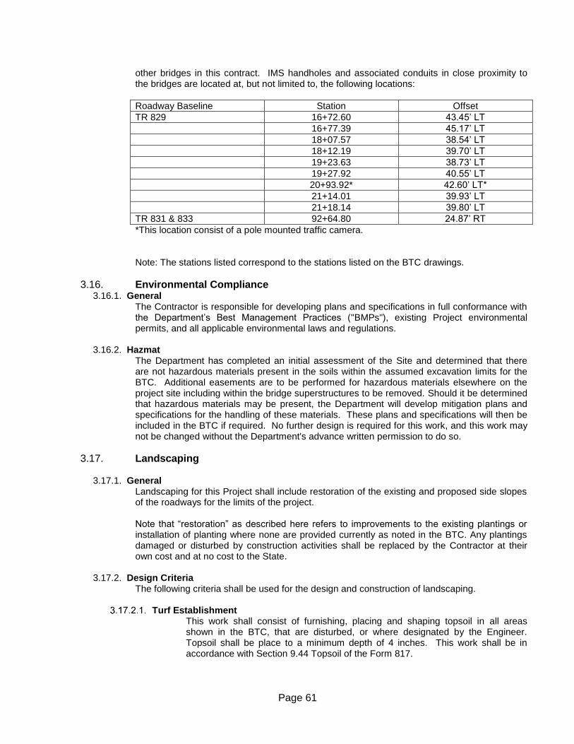
Page 61
other bridges in this contract. IMS handholes and associated conduits in close proximity to the bridges are located at, but not limited to, the following locations:
Roadway Baseline Station Offset
TR 829 16+72.60 43.45’ LT
16+77.39 45.17’ LT
18+07.57 38.54’ LT
18+12.19 39.70’ LT
19+23.63 38.73’ LT
19+27.92 40.55’ LT
20+93.92* 42.60’ LT*
21+14.01 39.93’ LT
21+18.14 39.80’ LT
TR 831 & 833 92+64.80 24.87’ RT
*This location consist of a pole mounted traffic camera. Note: The stations listed correspond to the stations listed on the BTC drawings.
3.16. Environmental Compliance 3.16.1. General
The Contractor is responsible for developing plans and specifications in full conformance with the Department’s Best Management Practices ("BMPs"), existing Project environmental permits, and all applicable environmental laws and regulations.
3.16.2. Hazmat
The Department has completed an initial assessment of the Site and determined that there are not hazardous materials present in the soils within the assumed excavation limits for the BTC. Additional easements are to be performed for hazardous materials elsewhere on the project site including within the bridge superstructures to be removed. Should it be determined that hazardous materials may be present, the Department will develop mitigation plans and specifications for the handling of these materials. These plans and specifications will then be included in the BTC if required. No further design is required for this work, and this work may not be changed without the Department's advance written permission to do so.
3.17. Landscaping
3.17.1. General Landscaping for this Project shall include restoration of the existing and proposed side slopes of the roadways for the limits of the project. Note that “restoration” as described here refers to improvements to the existing plantings or installation of planting where none are provided currently as noted in the BTC. Any plantings damaged or disturbed by construction activities shall be replaced by the Contractor at their own cost and at no cost to the State.
3.17.2. Design Criteria
The following criteria shall be used for the design and construction of landscaping.
Turf Establishment This work shall consist of furnishing, placing and shaping topsoil in all areas shown in the BTC, that are disturbed, or where designated by the Engineer. Topsoil shall be place to a minimum depth of 4 inches. This work shall be in accordance with Section 9.44 Topsoil of the Form 817.
Page 62
This work shall consist of providing an accepted uniform stand of established perennial turf grasses by furnishing and placing fertilizer, seed, and mulch on all areas to be treated as shown in the BTC, that are disturbed, or where designated by the Engineer. This work shall be in accordance with Section 9.50 of the Form 817
Landscaping Establishment
This section intentionally left blank.
Hazard Trees
. At Bridge Nos. 02366, 02367, and 02369, trees and shrubs that inhibit sightline shall be trimmed or removed at the bridges and approaches. Minimum stopping sight distance at these bridges is 425 feet. At Bridge No. 00847 Willington, trees and shrubs shall be trimmed or removed to provide sightline at the bridge and at the three driveways west of the bridge and to the first driveway to the east of the bridge. Passenger car intersection sight distance for 35 mph design speed is 390 feet with the location of eye 15 feet from the edge of road desirably; however, can be measured from edge of traveled way where restrictions limit offset. The height of eye for passenger cars is assumed to be 3.5 feet above the surface and the height of the approaching object is assumed to be 3.5 feet.
3.17.3. Drawings
Plans shall delineate slopes and areas that shall have topsoil, turf establishment, and sightline trimming. Plans shall be submitted demonstrating both horizontal and vertical sightline.
3.18. Construction
3.18.1. General
Before construction activities may begin for a specific segment or component of the Project, the Contractor must have met all requirements for “Release for Construction,” as well as the other requirements of this RFP related to pre-construction submittals, approvals and notifications. These pre-construction submittals include, but are not limited to, shop drawings, working drawings, testing, schedule and public information. All design and construction documents shall be prepared using the English system. The Contractor shall construct the work incompliance with this RFP, with the following objectives as guides:
Attain the highest quality product possible.
Keep the Stakeholders informed of the work and use public outreach to reduce congestion.
Successful performance of the Design-Build Project.
Completion of the Project within the estimated Contract time.
Completion of the Project within the Proposed Price.
Successful application of ABC technologies.
Maximum beneficial use of innovation. Innovate when possible in order to achieve the best results possible.
Minimize the detrimental effects of the work on the Transportation System and the neighboring community.
Page 63
Maintain or improve, to the maximum extent possible, the quality of existing traffic operations, both in terms of flow rate and safety, throughout the duration of the Project.
Minimize the number of different Traffic Control phases, i.e., number of different diversions and detours for a given traffic movement.
Take advantage of newly-constructed portions of the permanent facility as soon as possible when it is in the best interest of traffic operations and construction progress and quality.
Maintain direct access to adjacent properties at all times, with the exception of areas of limited access right-of-way where direct access is not permitted.
Properly coordinate with entities working on adjacent construction projects and on maintenance of existing facilities.
3.18.2. Submittals All submittals shall be made in accordance with the RFP. Unless otherwise specified, the Contractor shall seek guidance from District personnel administering the Contract as to the proper recipient(s) of such submittals to.
Shop and Working Drawings
All Shop and Working Drawings shall be reviewed and approved by the Designer of Record, Contractor’s Lead Designer, Project Manager, Superintendent and Quality Control Manager for Construction and Quality Control Manager for Design) prior to submission to the Department, as required elsewhere in this RFP.
RFI and RFC
The Special Provision, "Document Control Specialist" contains review timeframes and other requirements for these submissions.
3.18.3. Construction Survey
The majority of the requirements related to construction staking are included in the Special Provision for “Construction Staking” included in Appendix [A.02].
Baselines The construction baselines shall be staked in the field, offset and maintained throughout Project construction. Baseline stations shall be staked at every fifty (50) feet (stations and half-station), point of curves, points on curves, points of tangency, and other locations as necessary. The control shall originate from the Project survey control and be verified by physical features. Record baselines are included on the base survey. The Contractor shall be responsible for tying any newly-created baselines to the record baseline.
Construction Survey related to ABC Techniques Any use of ABC techniques will require additional construction survey efforts in order to conform to the requirements of the "Construction Staking" Special Provision. For this work, the Contractor shall use licensed surveyors to perform survey of the constructed bridge substructure and to verify at the time of the pre-assembly of any portions of the superstructure that the superstructure will match the substructure necessities and related plan requirements.
3.18.4. Issue Escalation/Resolution
The Contractor shall have the necessary personnel available at all times to resolve construction issues in order to expedite the construction progress and ensure a quick resolution of Project issues that otherwise would delay and, in some cases, hinder the progress of Project construction. The Department representatives shall be kept apprised of all
Page 64
issues and proposed solutions and will be afforded a review of proposed solutions or resolutions prior to their implementation. Lines of communication between Contractor personnel and Department personnel should always be open, and cooperation in the field shall be treated as being of paramount importance in resolve Project issues as soon as possible. In the event that an issue cannot be resolved at a certain staff level in a timely manner, either due to its complexity or lack of sufficient authority, the Contractor and Department representatives shall promptly elevate the issue in their respective chains of command, as appropriate and necessary, in order to resolve the issue in as timely and effectual a manner as practicable.
Page 65
Environmental Approvals
4.1. Acquired Environmental Approvals The BTC developed by the Department requires certain design, construction, and mitigation measures to be taken for this Project. The Department has already taken significant steps to clear the way for said measures, including obtaining initial determinations for the need for any necessary permits from regulatory agencies and meeting with those agencies and with the public to discuss the Project. Project Need Determination Forms (PNDF) have been prepared by the Department based on the BTC and initial assumption of possible activities to be undertaken by proposers under this project. These assumptions are preliminary and not guaranteed to be fully representative of the final means and methods to be undertaken by the Contractor. Proposers shall fully review the PNDF provided in Appendix B for all preliminary information Developed by the Department and used to make any initial permit need determinations shown and shall identify any information shown that is potentially in conflict with their proposed means and methods, including all temporary and final work and means and methods of construction. Based on the information shown in the PNDFs, a General Permit for Discharge of Stormwater and Dewatering Wastewaters from Construction Activities will not be required for this project. The total area on site where soil will be exposed or susceptible to erosion during the course of all phases of the project has been assumed to not exceed 1 acre. The Contractor is expected to not work beyond the given threshold of 1 acre. Should the Contractor adhere to the disturbance areas noted on the PNDF, no additional stormwater will be required for this project. Should the Contractor perform work beyond the given threshold of 1 acre, additional permits including but not limited to a General Permit for Discharge of Stormwater and Dewatering Wastewaters from Construction Activities may be required. Any work which takes place as part of this project which triggers a permit of any kind will be the full responsibility of the Contractor. Proposers shall identify in their proposals if additional permitting efforts are necessary. The Contractor will not work within regulated wetland areas as delineated on survey. The Contractor should be conscious of drainage pipes, outlets and appurtenances, and not damage any during the construction phases. If drainage infrastructure or appurtenances are damaged during construction, there repair will be the responsibility of the Contractor along with all design and regulatory requirements as required by CT DOT, in order to bring the damaged areas back into compliance The Contractor will be required to finalize coordination with Windham Water Works (WWW). This coordination includes notifying WWW of the construction start date. Comments noted in the initial coordination with Windham Water Works are expected to be included in the design. An amended Section 1.10 Spec has been included in this document. No additional environmental approvals or permits for the Project will be needed by the Contractor if it completes the Project in accordance with the BTC and in conformance with the information shown in the PNDF’s provided. Requirements for environmental compliance by the Contractor are outlined in Chapter 1.10 of Part 3 of this RFP. Any changes or revisions of the conditions of the Project by the Contractor through its final design or through the submission and approval of an ATC shall make it necessary for the Contractor to provide all documentation required for any application for any such environmental approval or any amendment of any such environmental approval. Any such changes of Project conditions must be coordinated through the Department, since the Department is the official applicant for such approvals. The Contractor is encouraged to develop a close working relationship with the Department for the purpose of ensuring that its designs will be acceptable to the Department and to regulatory agencies from an environmental perspective. The Department takes no responsibility for any time delay or cost associated with related submissions that are refused, rejected, conditioned or modified by the
Page 66
Department or any regulatory agency, or for any redesigns that such agencies or the Department require from the Contractor.
4.2. Stormwater Pollution Control Plan
No Stormwater Pollution Control Plan has been developed for the BTC based on the estimated area of disturbance in the PNDFs. Any proposed changes to the BTC may require registration under the General Permit for Discharge of Stormwater and Dewatering Wastewaters from Construction Activities. This may include the need for creation of a Stormwater Pollution Control Plan which shall include stormwater management measures. This may also require designing and constructing improvements by the Contractor to any outfalls within the project found to be deteriorated or substandard. The Contractor will be responsible for supplying the Department with all the required documentation for obtaining the applicable permits or modifications of existing permits necessitated by such changes. The Department will not allow the Contractor to revise the Project schedule because of any change to the drainage design or associated permits.
Page 67
Utilities
5.1. General Statement The Department has conducted preliminary coordination with the owners of utilities to be affected by the Project. Final utility coordination will be the responsibility of the Contractor, which should expect to devote resources to such coordination as may be necessary in order to complete the Project. The Contractor will be required to protect existing utilities from construction activities and shall comply with the requirements of Section 5.4. The Contractor shall provide sixty (60) days’ notice to the Department of any need to have a utility owner relocate any of its facilities. If the Contractor damages any utility assets, it shall notify the affected utility owner(s) and the Department of same, and it shall assume any costs related to repair of those assets. The Contractor shall ensure that any utility work that it performs on the Project complies with the latest “Buy America” provisions. Any proposed change to the BTC that results in an increase in utility relocations or modifications will constitute an ATC. All justifications for the utility adjustments shall be stated in the ATC submission.
5.2. Contractor Responsibilities The Contractor shall coordinate with the Department regarding any Project activities that may affect the services or facilities of a private, state or municipal utility entity. The Contractor will be responsible for coordinating with the Department and utility owners to arrange for required utility relocations on the Project. Other Sections in this Chapter and the BTC plans contain detailed information regarding that work. The Contractor shall meet with the Department and all owners of affected utilities within thirty (30) days from the award date for the purpose of briefing such utilities on proposed construction schedules, detours, etc. If during the development of the design the Contractor realizes that the proposed design will change the Project's effects on any utilities from what is indicated in the BTC, the Contractor shall immediately notify the Department of same. The Contractor shall then be required to submit preliminary design plans to the Department for review and approval prior to incorporating the changes into the Project. In addition, the Contractor shall be responsible to communicate changes or alterations of the proposed construction to the affected utilities and to assume responsibility for all additional costs and negotiations regarding the effects on utilities. Permits may be required to work in the vicinity of existing utilities. It will be the responsibility of the Contractor to obtain any such permits sufficiently in advance of the work's commencement. Any costs related to acquisition of utility permits will be borne by the Contractor.
5.3. Ascertaining the Location of Utilities The utilities shown on the BTC survey are based on limited investigations and are not guaranteed to be accurate or comprehensive. The Contractor bears full responsibility for ascertaining the existence and exact location and size of all utilities on the Site.
5.3.1. Existing Utilities Known to the Department
The BTC documents and all other documentation reflect the early coordination process engaged in by the Department. The Contractor will be responsible for confirming all existing conditions in the field prior to commencing work.
Page 68
The following is a list of utility owners with facilities on the Site and those that are likely to be affected by the construction, as determined during the preliminary investigations by the Department. Additional utilities may be affected by certain Project activities depending on the final design and the construction methods chosen by the Contractor.
Department of Transportation Electrical The Department maintains electrical services on the Sites of Bridge No. 02366, 02367, 02369 and 00847 that feed power to the applicable bridge, roadway lights, and VMS facilites. The electrical requirements for this Project generally include demolition of portions of the existing electrical systems and the installment of a new electrical power distribution system for these facilities The BTC does not includes specific locations of all new lighting features as this is considered part of the final design. In general, the new features replace existing features, in kind, with minor changes. The Contractor will be responsible for the final design, detailing and construction of such facilities.
Communications Frontier Communications Company and Contact Person:
Mr. Eric Clark Construction Manager – Statewide Structures Access Frontier Communications of Connecticut 1441 North Colony Road Meriden, CT 06477 Project Contact: Karen Garofalo 203-237-2681
The proposed work and temporary construction for Bridge No. 00847 may conflict with an aerial cable located on the west side of Potter School Road affixed to utility poles. The Contractor is responsible for the coordination of any relocation or any work to protect and maintain in place required to complete the work under this contract. The work shall comply with Frontier Communications requirements.
Communications
Charter Communications Company and Contact Person: Mr. Theodore J. Michaud Construction Supervisor Charter Communications Entertainment, LLC. 207 Tuckie Road North Windham, CT 06256 860-4568346 ext. 53070
The proposed work and temporary construction for Bridge No. 00847 may conflict with an aerial cable located on the west side of Potter School Road affixed to utility poles. The Contractor is responsible for the coordination of any relocation or any work to protect and maintain in place required to complete the work under this contract. The work shall comply with Charter Communications requirements.
5.4. Special Requirements for Commencement of Work near Utilities Special attention must be given to the placement of cranes and to the paths of delivery vehicles and equipment within the project limits. There is a buried utilities under at the west side of Bridge No. 02369 which may be susceptible to damage from construction equipment. The Contractor shall provide the Utility companies with a detailed description and plans for the proposed crane placement, including any placements that may be shown as part of the BTC, and the proposed path of delivery vehicles and construction activities within the Project limits for review and
Page 69
comment. The Contractor must demonstrate to the Department that all utility company concerns and comments have been addressed prior to the commencement of construction activities involving heavy equipment or delivery vehicles within the Project limits. Special attention must be given to the operation of cranes and the operation of construction equipment within the project limits. There are overhead utilities at the west side of Bridge No. 00847 which may be susceptible to damage from construction equipment. The Contractor shall provide the Utility companies with a detailed description and plans for the proposed crane operation, including any operation that may be shown as part of the BTC, and the proposed operation of construction vehicles and construction activities within the Project limits for review and comment. The Contractor must demonstrate to the Department that all utility company concerns and comments have been addressed prior to the commencement of construction activities involving heavy equipment or delivery vehicles within the Project limits. The Contractor shall comply with the “Call Before you Dig” requirements contained in Part 3 of this Contract for all work.
5.5. Meetings and Cooperation with Utility Owners The Contractor shall coordinate meetings with the owners of utilities whose facilities or services will likely be affected by Project activities, in order to make certain that Project construction can be completed. Such meetings may entail, for instance, obtaining information, or coordinating activity scheduling, design review, inspections, or various kinds of approvals. The Contractor shall notify the Department of all utility coordination meetings and shall not conduct a meeting without a Department representative being present. The Contractor shall copy the Department on all correspondence with utility owners related to the Project. The Contractor shall immediately notify the Department if the Contractor becomes aware that a utility owner(s) is not cooperating in providing needed work or approvals. The Department agrees to make reasonable efforts to assist the Contractor in obtaining the cooperation of utility owners, but such assistance shall not be relieve the Contractor of its sole responsibility for the satisfactory compliance of its Contractual obligations in this regard. The Contractor shall incorporate all utility phases of construction into the overall work schedule. No additional time or compensation will be provided as a result of delays due to a need for utility coordination or staging. The Contractor shall be responsible for all work associated with or necessitated by the need to continue expeditious Project completion despite the presence of or conflicts with utilities on the Site. The Department will be responsible for checking and verifying material quantity and labor hours submitted by the utility companies in requests for compensation for costs or damages connected with the Project.
5.6. Avoiding Relocations The location of utilities and the potential effects on the Project of utility relocations shall be considered by the Contractor in developing any proposed changes to the BTC, with the following goals:
Avoiding relocations.
Protecting the utility in place to the extent practicable, if a relocation is not reasonably avoidable.
Minimizing potential costs and delays related to relocations.
5.7. Scheduling and Cost Risks The Contractor shall be solely responsible to communicate to affected utilities and to the Department any changes or alterations that the Contractor proposes to make regarding utility relocations contemplated in or necessitated by the BTC. In addition, the Contractor shall also be responsible to communicate to those parties any changes or alterations that it proposes to make regarding the
Page 70
proposed construction staging, insofar as they might affect the timing of utility relocations. Should the Contractor propose for its convenience any relocations other than those described in the RFP, the Contractor shall be responsible for any additional costs and any scheduling changes caused by those relocations. In the event of any changes to the staging or scope of utility relocation work contemplated in or necessitated by the BTC, it shall be the Contractor’s responsibility to mitigate any negative effects that those changes might have on the Project progress or schedule; and the Department will not grant additional payment or Contract time to the Contractor in connection with those changes. This includes effects on the meeting of Project milestones with related incentives or liquidated damages.
5.8. Utility Work Prior to Schedule Submission If the Contractor anticipates that utility work will need to start before the first submission of a schedule required by the Contract, the Contractor shall inform the Department of the relevant facts, providing an Initial Schedule detailing when each early utility activity is required to start either (1) at the pre-construction conference, or (2) at the time of the initial schedule submission required by the Contract, whichever is earlier.
Page 71
Right of Way
6.1. General Statement No right-of-way acquisitions have been included in the BTC and no right-of-way acquisitions have been acquired by the Department. No acquisition for construction access or temporary work zones are anticipated at this time. The Proposer must evaluate and verify that the Right-of-Way limits shown on the BTC plans are adequate for completion of the Project prior to submitting its proposal. Any proposed need for acquisition of any property easements or acquisitions for construction of the permanent or temporary work at the Site will constitute an ATC. The Proposer will be required to propose and gain approval of the ATC as outlined elsewhere in this RFP. Should permanent property acquisitions or temporary property rights be deemed necessary for the construction of the work at the site, through the Departments acceptance of an ATC proposal for the completion of the project, the Department will acquire the pertinent property acquisitions or rights. The Proposer agrees to the condition, through its submittal of the ATC and Proposal that the Department cannot guarantee a timeframe for the acquisitions or rights and shall not be liable for time impacts or increased costs to the project related to additional acquisitions or rights based on a proposal that requires such. The Proposer also agrees, through submission of the ATC that, potential additional costs for property acquisition or rights may be the responsibility of the Proposer as determined through the ATC process. Should the Contractor require any additional property rights for its convenience during construction, for storage and staging areas on or off the site, it shall provide the Department with copies of said agreements prior to impacting or occupying property. These agreements will be subject to review and approval by the Department. The Contractor must ensure that all the conditions included in these agreements are met prior to the final acceptance of the Work.

Page 72
Railroad Chapter intentionally left blank.