draft quality assurance program plan for multi-task
TRANSCRIPT

201386
D»AFT
ffcOtjCAAA QUALITY ASSURANCE MM PLAN
FOR
MULTI-TASK CONTRACT FOR REMEDIAL . MEASURES AT UNCONTROLLED HAZARDOUS
WASTE SITES
EPA Contract No. 58-03-3113
APPROVALS:
JRS Associates
Robert A. Colonr.a Pro^e^t Manager
Signature Date
Richard V/^Sawards Project /gjailrcy, Assurance Officer
KI ' /1/,.̂ . ,<— Signature Date
Environmental Protection Agency
Frank J. Preestor.e Project Officer
•s-
Signature Date
Donald Sanning
Project Officer-
/ C f . . . u( 1 ( , . . • . .
Signature J
/
Date
Lawrence Kamphake Quaiitv Assurance Officer /
^ /Date Signature
001
268204
llllllllil

SssUor.
i.o
2 . 0
3-0
tt.O
5.0
5.0
7.0
3.0
9.0
10.0
n.o
12.0
13.0
:a.o
15.0
TABLE OF CONTENTS
EaSSfl. Revision Date
JRP's Ability to Implement a Quality Assurance Program
Project Description
Project Organization and Responsibilities
Quality Assurance Objectives
Sampling Procedures
Sample Cust^dv
Calibration Procedures and ?reouencv
Analytical Procedures
Data Analysis, Validation and Reporting
Internal Duality Control Checks ana Freouen.cy
Performance and System Audits ana Frequency
Preventive Maintenance Procedures and Schedules
Specific Procedures to be Used to Routinely Assess Data Precision, Accuracy and Completeness
Corrective Action
Quality Assurance Reports to M a n a g e m e n t . . . . . . . . . . . . . . .
Appendix A Standard Operating Procedures
Appendix B Quality Assurance Project Officer Resume
Appendix C Bibliography
002

Section Mo. 1 3 evis lor. Mo. 1
Date 7/5/R2 Page 1 of 6
1.0 JRB'S A5ILITY TO IMPLEMENT A QUALITY ASSURANCE PROGRAM
JRB's Ouality Assurance (OA) program ensures generation of measurement
data of adequate quality to meet the specifications of the "Multi-Task
Contract for Remedial Measures at Uncontrolled Hazardous Waste Sites". It also ensures the high quality of general project management responsibilities,
including records and reports, facilities ana equipment, performance ana system audits, and corporate corrective action or follow-up.
JRB's OA program is designed to oversee the activities of JRB as well as
our subcontractors and consultants. JRB recognizes the extreme importance of
strict qualitv assurance for ail work performed under this contract because of
our past experience, ana can tailor our OA program to meet the specific aemar.ds
of all task areas.
The adherence to OA procedures for technical ana enforcement support
ensures that ail data presented are as scientifically sound and statistically accurate as possible.
These qualities are essential for litigation and prosecution proceedings
that may arise from the types of activities which will be conducted in this
contract. Specific OA procedures related to activities such as sample
collection, flow monitoring, laboratory analysis, engineering data reduction, and document control will ensure that data are fit for enforcement support.
In addition, OA procedures for other project activities, such as employee credentials verification ana company-wide compliance with DCAA accounting
practice, etc., will ensure high quality ana cost effective project management, products and services. Without a total OA program, work efforts performed
would be of limited use and sometimes invalid.

Section wo. 1 Revision Mo. i
Date 7/5/82 Paee 2 of 5
1.2 JRB ORGANIZATION CHART
A JRB organizational chart is presented in Fiaure 1, and demonstrates
direct reporting by the Quality Assurance Director to the President. It also
displays the Quality Assurance Director's overall authority to interact with
th9 other functional groups of the organization.
1.3 JPB CORPORATE QUALITY ASSURANCE POLICY STATEMENT
To reinforce the corporate commitment to excellence, a corporate-wide Quality Assurance Program (QAP) is being established. This program will supple
ment the traditional and continuing role of the project manager who carries the primarv responsibility for qualitv assurance on individual projects. It
will establish the President of the company as the corporate officer responsible for Quality Assurance at JRR.
The corporate QA? will be apolied to every ar®a of JRS's activities. It
will cover especially those aspects of QA which extend beyond individual projects or are common among projects, such as the following:
• Fulfillment of every JR8 commitment to quality, integrity, ana propriety
• Identification, anticipation, and avoidance of potential risks
• Corrective actions
• Establishment of senior review for selected products
• Credibility and credentials of personnel
• Liaison with client organizations regarding overall QA policies and practices
• In-house staff training
• Authenticity of past project achievement descriptions
• Establishment of QA policies and procedures for all JRB activities.
\
004

Section Mo. I Revision Mo. I
Date 7/6/92 page 3 of 6
JRB
*M Hitfim am mimaa io oct tor PfOMOom md umn a* ipcm i
FIGURE 1-1. JRB Organizational Chart
005
Section No. 1 Revision 'io. i
Date 7/6/32 page u of 5
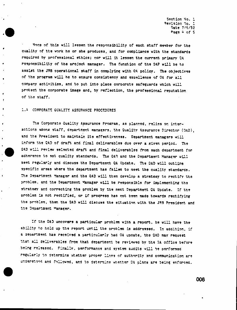
None of this will lessen the responsibility of each staff member for the quality of the work he or she produces, and for compliance with the standards required by professional ethics; nor will it lessen the current primary QA responsibility of the oroject manager. The function of the 3AP will be to
assist the JR8 operational staff in complying with 0A policy. The objectives of the program will he to ensure consistency and excellence of OA for all
company activities, ar.d to put into place eoroorate safeguards which will protect the corporate image and, by reflection, the professional reputation
of the staff.
l . ' - i CORPORATE QUALITY ASSURANCE PROCEDURES
The Corporate Quality Assurance Protrram, as planned, relies on inter
actions anor.a staff, department managers, the Quality Assurance Director (DAD),
and the President to maintain its effectiveness. Department managers will
inform the QAD of draft and final deliverables due over a given period. The
QAD will review selected draft and final deliverables from each department for adherence to set quality standards. The QAD and the Department Manager will
meet regularly and discuss the Department QA Update. The QAD will outline specific areas where the department has failed to meet the quality standards.
The Department Manager and the QAD will then develop a strategy to rectify the problem, and the Department Manager will be responsible for implementing the
strategy and correcting the problem by the next Department QA Update. If the problem is not rectified, or if progress has not been made towards rectifying
the problem, then the QAD will discuss the situation with the JRS President and the Department Mar.ager.
If the QAD uncovers a particular problem with a report, he will have the
ability to hold up the report until the Droblem is addressed. In addition, if a department has received a particularly baa QA update, the QAD may request
that ail deliverables from that department be reviewed by the DA office before
being released. Finally, performance and system audits will be performed
regu.arly to determine whether proper lines of authority and communication are
understood and followed, and to determine whether QA plans are being enforced.
006

Section 'Jo. 1 Revision Vo. i
Date 7'6'S2 Paae 5 of 5
A written, report, prepared at the conclusion of each audit, will become a part of the official record for each contract.
This program will work because:
• The OAD is responsible to the Dresident and not to the department managers.
• The OAD randomly samples deliverables so project personnel are not aware of which deliverables will be reviewed.
• The QAD and the department manager regularly discuss Department OA progress and develop strategies to correct deficiencies.
• The OAD can hold up reports if major QA problems are discovered.
• Primary responsibility for OA remains with project and department managers.
1.5 CORRECTIVE ACTION FOLLOW-UP PLAN
The Duality Assurance Director (OAD) will be empowered to take anv
corrective action necessary to preserve quality control of project activi
ties. He will have the full support of the project manager and qualitv
control representatives of our subcontractors. In the event that corrective
action is needed ana the project manager is unable to help resolve the
situation, the OAD and the project manager will enlist the support of JRB's President.
One of the critical roles of a QA/QC program is the implementation of
corrective actions ir. the event that a problem is encountered. During the
lifetime of a project, aar.v problems, both large and small, mav be encountered.
The OAD will document these problems ir. a formal report to be sent to the pro
ject manager, who has the primary responsibility for making the appropriate
corrections. If the problem is discovered internally, he may simply correct
007

Section Mo. 1 Sevisior. No. 1
Oate 7/5/32 Page 5 of 6
the problem within hie staff or he nay consult with the relevant parties to plan the proper course of action. If the problem is discovered bv external
audit, the project manager must consult with the OA staff prior to imple
menting corrective measures. All remedial procedures will be documented ana,
along with the initial report, will become a part of the permanent, project file.
008
Section No. 2 Revision No. 1
Date 7/6/3? Page 1 of 2
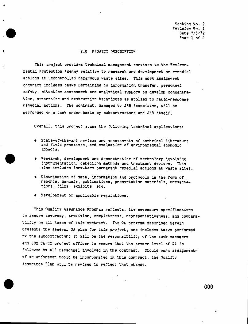
2.0 PROJECT DESCRIPTION
This project Drovldes technical aanagement services to the Environ
mental Protection Agency relative to research and development or. remedial
actions at uncontrolled hazardous waste sites. This work assignment
contract includes tasks pertaining to information transfer, personnel safety, situation assessment and analytical support to develop concentra
tion, separation and destruction techr.ioues as applied to rapia-respor.se remedial actions. The contract, managed by JE8 Associates, will be
performed or. a task order basis by subcontractors and JR8 itself.
Overall, this project spans the following technical applications:
• State-of-the-art reviews and assessments of technical literature and field practices, and evaluation of environmental economic impacts.
• "esearch, development ana demonstration of technology ir.volvirjr instrumentation, detection methods and treatment devices. This also includes low-term permanent remedial actions at waste sites.
• Distribution of data, information and protocols in the form of reports, manuals, publications, presentation materials, presentations, films, exhibits, etc.
• Development of applicable regulations.
This Quality Assurance Program reflects, the necessary specifications to assure accuracy, precision, completeness, representativeness, ana compara
bility on all tasks of this contract. The OA program described herein
presents the general QA plan for this project, and includes tasks performed
bv the subcontractor; it will be the responsibility of the task managers
ar.a JR3 QA'QC project officer to ensure that the proper level of QA is
followed bv all personnel involved ir. the contract. Should work assignments
of an ur.forseer. topic be incorporated in this contract, the Qualitv
Assurance ?lar. will be revised to reflect that change.

Section Mo. 2 Revision Mo. 1
Date 7/6/32 Page 2 of 2
It will be necessary to prepare specific QA plans for those individual tasks which include research, monitoring and measurement activities which generate and process environmentally related data as part of the deliverables.
It is important to note, however, that where several research tasks have
essentially similar QA requirements, the same plan may cover all of them.
2.1 DE?r»ITIOMS
For this plan, the following terms are defined:
• Data Quality: The totality of features and characteristics of data that bear on their ability to satisfy a given purpose. The characteristics of major importance are accuracy, precision, completeness, representativeness, ana comparability.
• Quality Assurance (OA): An organization's total system of activities for assurine the reliability of the data is produces. This system integrates the quality planning, assessment, and improvement efforts of various aroups in the organization to ensure that the requirements of the project are met.
• Quality Assurance Officer (QftO): The J"B staff member with overall responsibility for Quality Assurance for the contract activities. The CAO reports directly to the JBB Corporate President.
• Quality Assurance Program Plan: An orderly assembly of mar.aee-rnent policies, objectives, principles, and general procedures by which an organization outlines how it intends to produce cuality data.
• Quality Assurance Pro<ect Plan: An orderly assembly of detailed and specific procedures by which an organization delineates how it produces quality data for a specific project or measurement method. An organization may have only one ouality assurance program plan, but would have a quality assurance project plan for each of its projects.
• Cualltv Control (CC): The routine aoplicatior. of procedures for obtaining prescribed standards of Derformar.ee in the monitoring and measurement process.
010

Section Mo. 3 Revision Mo. 1
Date 7/5/32 page i of 5
3-0 PROJECT 0PCAMIZATI0W AMD RESPONSIBILITIES
This section describes each JRB management function, both technical ana Quality Assurance (OA), and describes how we plan to ensure the highest
possible standard of quality at each level.
Proiect Manager
Mr. Robert A. Colorna, JRB's project mar.aaer, has overall responsibility
for technical quality, cost control, project personnel management, ana
adherence to schedules. His overall management involves the quality assurance of the following items:
• Work Plans ,
• Deliverable Resorts
• Subcontractor ana Consultant Work Products
• Adherence to Delivery Schedules
• Cost Control ar.a Cost Accounting on the proj°ct
• Performance of Key Personnel on the Tasks
Mr. Color.r.a reports directly to Mr. Gregory Woods, President of JRB. The
organization of this project is shown in Figure 3-1. on the following page.
His primary interfaces at EPA are with the project officer and the contracts specialist.
Task Area Managers
Six task area managers have been assigned to cover the malor task areas encompassed by this project. Tasks have not been assigned ir. all of these
task areas as of this date. The task area manager is the first technical
person involved when a work assignment is made. The task area manager,
011

PREMIUM , IRU
liri'UHi y Wood*
PROJECT MAIIACER
Robert A. Co I oiin j
i.v. i: A R I A I :
I'lKMINAl. S.MI IV
Mr . Coirge I.iwIimi
TASK 4 » : IMIRCEUCY RESPONSI
Rolicit A. Co I oho.i
TASK AREA ?:
SITUATION ASSESSMENT Alil>
ANALYTICAL SUPPORT
Manager; Mr. Joint Simmons
I _ . .
.. i TASK AREA 1:
CONCENTRATION ANI) SEPARATION
Manager: To be Named
TASK AREA 4:
CONTAINMENT ANN ENCAPSULATION
Manager; Mr. Roger IJettel
4)UAI ITV ASSURANCE PROJECT OEEICPR
Richard V. Edwards
~r
TASK AREA S:
DESTRUCTION TECIINII|ULS
Manager: Dr. Donald Michel son
TASK AREA 6:
LONC-TERM PERMANENT REMEDIAL MEASURES
Manager: Mr. Charles Kola
J I Profeuwlonnl Staff, Ollie I Took Managers, Subrontrocior I and Console (into
V I tore I
O tO
FICURH J-l Project Organization (Quality Assurance Reporting Relationships)
4J <D */> < (0 o o I-4- o ID ID U) (t n cr lfc J...
• 0 <D O o .1 ."3 ro -d *>» «S (J) O o N • • U0 rvi 1 •- u)

Section Mo. 3 ®»vls'or. Mo« 1
Date 7y5/S2 Page 3 of 6
along with the JPS project manager, and appropriate representatives from 3PA (project officer, task officer), meet to discuss the strategy of work plan
preparation. Thev then select a JflB task manager and assign him the responsi
bility for the task. The responsibilities of the task area manager include:
• Selection of task manager
• Selection of consultants (if necessary)
• Decision on whether to employ a subcontractor
• Supervision of task manager with respect to technical nuality
• Preparation of work plans
• Peview of work products
The task managers are responsible for technical performance on each task. They meet with SPA task officers during the work plan preparation ana during
the performance of the task. They also oversee consultants' and subcontractors'
work. Their responsibilities include:
• Tschnic&i• ouaiity of work plan
• Technical quality of work on their task
• Technical quality of subcontractors' work products
• Adherence to QA procedures
• Adherence to delivery schedules
Their primary interface with 3?A is the ~?' task officers ana staff. Task managers report to the appropriate JP3 tasK area manager.
013

Section Ho. 3 Revision Mb. i
Sate 7/6/32 °aee U of 6
TMS-IH QA^C Offi??r,
Mr. Richard Edwards has beer, assigned as the project 0A/9C officer because
of his technical, management and QA experience, and his familiarity with hazardous waste problems and issues. He has complete authority to enforce
auality assurance procedures on this project. This includes all activities performed by JRB and any of our subcontractors or consultants. In the case
where subcontractors have established their own quality control procedures and
lines of authority, Mr. Edwards will retain oversight authority to ensure that
all activities on this contract receive the recuisite level of Quality control. Mr. Edwards' resume is attached as an appendix to this plan. His responsi
bilities are:
• Management - The 9A0 will be responsible for ensuring that proper lines of communication are maintained during this project. He '-'111 routinely interview key staff to ascertain their knowledge ana understanding of selected oroject issues. He will also work closely with the Task Leaders in the work assignment planning stage. He will maintain the resume and Job description, of each person responsible for the design, supervision, conduct or analysis of ar.v study or test OP. this project for a period of three years following the performance of the activity.
• Technical Assessment - The 9A0 will be responsible for enforcing all Quality control procedures for work assignment final reports and deliverables. ?or certain critical documents, the 9A0 will ensure that the formal sign-off procedures are followed and that proper records are retained for the official project file. In particular, he will:
Review each work plan for 9A conformance and ensure appropriate revisions
Review a sample of work products on a Quarterly basis
- Review a sample of draft final task reports
Review laboratory ar.d testing procedures on a Quarterly basis
014
«

Section Mo. Revision Mo.
Date 7/6/3 Page 5 of
- Review a sample of each subcontractors' work products on a quarterly basis
- Review project cost accounting orocedures quarterly
- Review delivery schedule comoliance on a quarterly basis
- "sport his findings or. each of the above items to the SPA OA officer and to JRB's President on a quarterly basis
- Make corrections and updates to the QA/OC plan as needed
- Provide feedback to the JRB project manager on problems with duality so that corrective actions can be taken
- Training - The QAO will be responsible for determining staff training needs, and for ensuring that the proper training . takes place to meet the training needs.
- Sampling ana Laboratory Analysis - The QAO will require strict adherence by JRP's project team to establish monitoring and sampling procedures and laboratory protocols. The details of this aspect of our Quality Assurance Program are presented in JR9's sampling ar.d analysis protocols. These protocols address such factors as monitoring and sampling controls; transport and storage of sampling; laboratory protocols; accuracy and precision checks; and data handling and verification procedures.
- Confidential Document Control - The QAO will monitor the activities of JRB's Document Control Officer to ensure that J»B's Security Plan is being enforced. The details of our plan include such factors as access to confidential business information, storage and retrieval of confidential documents, document control log, proper disposal of confidential information, ar.d computer security procedures.
Plan Review. Approval and Distribution
Each specific QA °rojeet Plan shall be approved by the JRB Project
Manager, JRB QAO, the EPA Project Officer and other EPA personnel (such as '
the MERL 0A0) as specified by the Agency. Environmental measurements
will not be initiated until the specific OA Project Plan has received the
necessary approvals.

Section Vo. 3 Revision Vo. I
Da*.s 7/6/32 Page 6 of 5
A copy of the approved QA °roject Plan shall be distributed by the Project
Manager to each person who has a major responsibility for the quality of the measurement data. In addition, one copy of the approved plan must be placed
in a permanent file by the QAO, Mr. Edwards.
For assigned tasks which involve the use of subcontractors, the QAO shall
be responsible for seeing that the involvement of the subcontractors in
environmental measurements are part of the specific OA Project Plan.
The QAO will work with the Project Manager and FPA Project Officer to
resolve any QA problems which arise. He will submit a quarterly report
to the EPA Project Officer ana the JR3 Project Manager. In general, the
report will cover:
• Status of QA on project plans for the cuarter
• Data quality assessments
• Significant QA problems
• Results of system and performance audits.
raellltieg and Equipment
The reouihements for all program facilities ana eauipner.t are determined
by the kinds of measurements made in a particular task or project and the
specific objectives (both technical ana OA) of the program. Evaluation of
task-specific facilities ana equipment is the responsibility of the task area
manager. Evaluation of facilities and eauipmer.t for the program as a whole
are the responsibility of the Project Manager and QAO.

Section 'Jo. *» Revision Vo. i
Date 7/6'32 Page 1 of 3
U.O QUALITY ASSURANCE OBJECTIVES
Section 3.0 addressed management ana broader OA/QC functions. This section focuses on technical OA'OC as it relates to data development ar.d
analysis.
The objectives for QA on the TVS-III contract are to have the highest level of OA that is both possible and feasible. Because of the possibilities
of litigative suoport, the OA plan described here is targeted to be in accordance with MEPL Level I standards. JPB's current analytic protocols
encompass the CA procedures described herein ar.d it is not expected that a task will be performed that reduces these procedures to a lower level of
OA acceptability. While many of the TVS-III tasks will not reouire quantitative data collection, all tasks are expected to be conducted in an
accurate, precise, reproducible, representative, complete and comparable
manner. OA procedures will also be utilized for the tasks which are
largely composed of literature reviews and information collection. This
will ensure the credibility and reliability of the information aathered and
incorporated into the project reports. Should the EPA project and task
managers decide that a Level I OA effort is not necessary for a particular
task, JP9 will reduce the effort as directed.
When a w*rk assignment is given to JR3, QA objectives for a particular task will be described in the work plan. To do so, a detailed experimental
design for each task will be developed; once the technical considerations for the deslzr. have been developed, the OA objectives will be developed.
These objectives will clearlv state how accuracy, Drecision, representativeness, completeness and comparability will be determined during the perfor
mance of the task.

Section ?Jo. u Sevisior. Vo. I
Date 7/6/82 Page 2 of 3
Specifically, these objectives are:
• The data should be accurate in terms of their agreement with reference or true values.
• The data should be precise in that there is agreement among individual measurements made under similar conditions.
• The data should be complete in terms of the amount of data available versus the amount of data evaluated.
• The data should be representative of the overall population or data base.
• The data should be comparable to other data for evaluation ana testing purposes.
• The data should be reproducible under similar conditions, whether performed by same entity or another.
The auality assurance plan presented herein is intended to cover the major analytical parameters ana situations that are currently anticipated
on the 7MS-III contract, at a minimum to cover the general analytical
work. These procedures will be followed by all personnel on the project
incluaing subcontractors and consultants. If a work assignment includes functions that have not been previously addressed, JR3 will prepare a
QA/QC plan for the particular assignment. The task manager and OA project
officer will prepare the QA/QC plan. All "VA/QC plans will be submitted
to the £?A project officer for his approval. >
The TMS-III contract, as previously stated, covers a variety of
technical subjects and activities from literature searches and data analvsis
to detailed experimentation "and analytical worx. Much of this manual is
devoted to the analytical and sampling activities which will be performed
on this contract. Section 5.0 is devotee specifically to the sampling of
ambient air, water, sediments, soils, and waste materials at hazardous,
waste sites. Sampling other media such as stacks, biologic materials,
018

Section Mo. n Sevisior . Mo. i
Date 7/6/32 Page 3 of 3
etc. . are not currently anticipated in the contract so were not included in the manual. If a need was developed to sample these neaias, the Q4 manual
would be revised as previously discussed. Section 3.0 is devotea to
a n a l y t i c a l p r o c e d u r e s f o r t h e p r i o r i t y p o l l u t a n t s a n d o t h e r p a r a m e t e r s .

Section Mo. 5 Revision Mo. 1
Oate 7/6/32 Page i of i
5.0 SAMPLING PROCEDURES
Ultimate accuracy of any data generation activity begins with a sampling
procedure which is well conceived and implemented. Prior to sample collection,
a sampling plan with a clear purpose of analysis and methods to realize that
purpose will be prepared. This will be preceded by proper sample container
preparation, sample collection, preservation, and shipment requirements.
Sampling procedures that are recognized as standard methods by EPA must be utilized when applicable. (See Appendix A: Standard Operating Procedures)
020

Section No. 6 Pevisior. No. i
Date 7/6/32 °age i of 7
6.0 SAMPLE CUSTODY
A critical aspect of sound sampling ar.ci analysis protocols is the maintenance of strict chain-of-custody procedures. Chair.-of-custoay pro
cedures include inventorying ar.a record keeping during sample collection, shipment and laboratory processing. Proper record keeping is a must, and
Level I OA/QC guidelines will be used to ensure the sample custody procedures are aaeouate to support any legal challenges, as was discussed in
Section 4.0. The following specific information, at a minimum, will be entered in appropriate field logbooks; these notebooks will be official,
bound logs in which data are recorded in ink ana signed and dated with
each entry.
• Sample number assigned
• Sampling location description to include source(s)
• Detailed description of sampling method including a list of the settings on any equipment used in the sampling process
• Date ana time of sampling
• Name of individuals taking the.sample
• Amount of sample collected
• QA/QC procedures followed at the site - such as taking sample blanks
• If a composite, frecuer.cy of sampling ar.a volume of aliauots
• Plow information
• Observations
• weather conditions
• Field measurement such as temperature and pH.

Section Mo. 6 Revision Vo. 1
Date 7/6/92 Page 2 of 7
Each sample then will be uniquely and completely labeled immediately following collection. \ seal is attached to *ach saools container in such a manner that the container cannot be opened without breaking the seal. This seal will list
sample number, data and time of sample collection, and signature of the sampler;
it is designed to assure that the sample is not tampered with during shipment.
4 sampling chain-of-custody form shown in Figure 6-1 will be prepared. Such
a form will accompany the samples throughout the shipping and analytical
process. The chain-of-custody form includes:
1. Unique field sample number
2. Date and time sample taken
3- Date and time sample submitted to the laboratory
11. Sample taken bv (signature)
9. Information describing source of sample and its location
6. Sample matrix
7. Sampling method
3. Field chemist involved (signature)
9. Pemarks (expected interferences, hazards, unusual events at sampling, etc.)
10. Preservatives added (if any)
If more information on any sample is necessary, the appropriate field notebook pages are referenced on the chain-of-custody forms under "Remarks".
Samples are maintained under proper holding conditions by the field
chemist until custody is relinquished to the laboratory and formal documen
tation of such transfer is completed.
022

Section *Io. 5 Revision M0. 1
Date 7/5/32 Page ? of 7
noon receipt of samples in the laboratory, all samples are assigned a unique JR3 log number (cross-coded with the Project's field numbering) and pertinent information is recorded in a bound log book. This log number
applied to all analyses on the same sample and is recorded on the sample contair.er(s) in waterproof ink. Samples are stored and analyzed in accor
dance with standard methods previously set out in the work plan.
The laboratory task manager directs work performance for each sample using Analysis Request Forms, as in Figure 6-2. Copies of these forms are
eiver. to the chemist performing the analyses. For certain projects involving
multiple laboratories, instruments ana analysts, a sample tracking form is
used which accompanies each sample through the stages of analysis (example in Figure 5-3).
Each project or task is assigned a unique Project (or Task) File which
includes the work statement, the auproved work plan, the approved DA plan, all field documentation, analysis request forms, analytical results reports,
and copies of DA/QC forms for permanent records. Raw data sheets are also
included, as are cost tracking information and general correspondence ana
log books.
When samples are sent to another laboratory (split or otherwise) a sample shipment form is utilized (Figure 5-1). One copy of this form
remains in the project file ana another copy is sent with the transmitted samples.
After analyses are complete, samoles are archived or disposed according
to the requirements of the project or tasx, as stated in the contract or task work plan. Archived samples are so noted in the sample log book as
to conditions ana location.

SCUHCi APPIICAUOMS. INC. SAMPLE SHIPPING RECORD DIVISION OF ENVIRONMENTAL CHEMISTRY A GEOCHEMISTRY </6PHOSI>ECI Sllttei lA JOIIA. OA »W»3B . |/|4) 4S4-3BII
CONSIGNEE
SlMpoMmi Mo
iAI |lir| IktRH) 0"- | 1lOI» Rscsnud By (fttyn) | o« Time Received By Couner |t*on) I 0«. Time biM|4MfMj MuttMHl | Slupt^d By |hun| CcNMter hoin AmrotI f Mf n| | D... 1mm Received By Cooliacl I eb liignl 0«. Tone
WhllR-SAI Canary-Lob Representative Ptnk-Conlraci Lab Goldenrod-Lab Ralurns lo 8AI
so iO (A < «b v o i* n P) (I) (A (t
A c* |* I-* <D >D O O 3 rs *= -4
N 4 4 O JIQ o N • • u> >1 f\> I * u>
o IO -p.
I'Mjjure 6-1 CliaIn-of-Custody Record

Section Mo. 5 Revision Mo. i
Date 7/5/92 Pag? 5 of 7
3C ANALYSIS 3E0UE3T PORM
late Suomitted Person SuPmltting Samples
Contract Laoor and Analysis Charge No.
Samole No. Sample Type Analysis Aeculred
1 1 1
1
•
Standards Suomitted Do 'ou «ant These Analyses on Cassette Taoe? Chromatograms To Saoole Remainders To __ Date Analyses Reoulred _____ Comments or Suggestions -
Figure 6-2 Analysis Request Form

Sect lor. No. 7 Revision No. 1
Date 7/6/32 Paee 6 of 7
PROJECT NAME: PROJECT MUMS£3: _________ 34<«
COLLECTION LOCATION: SAMPLERS:
SAMPLE NUMBER DATs TINE SAMPLE T7PE
•# OF CONTAINERS
PRESERVATIVES ACQS REMARKS
1
1 1
1 1 1 1
II 1 1 • II II 1
II 1 1 RELINQUISHES 37: DATS/TIME:
REASON: RECEIVED 3Y:
RELINQUISHED 37: DATE/TIME: REASON:
RECEIVED 37:
RELINQUISHED BY: cats/time: REASON:
RECEIVE 37:
RELINQUISHED BY: DATLTIME: REASON:
RECEIVE 37:
RELINQUISHED 3Y: DATE/"" QMS: REASON:
REEVE 37:
RELINQUISHED BY: DATS/TIME: REASON:
REEVE 37:
Figure 6-3 Chain-of-Cuscody Log-In Sheet
026

Section No. 6 Revision No. 1
Date 7/6/32 Page 7 of 7
Results are reported on standard laboratory forms unless a project or task soeeifies a tailored reporting format. Reports are signed by the analyst and the reviewer; originals are supplied to the task manager and copies are kept
ir. the Task (or Project) File.
027

Section No. 7 Revision No. 1
Oats 7/6/82 Page i of 4
7.0 CALIBRATION PROCEDURES AND FREQUENCY
The following describes methods of performing calibration of the analytical
instrumentation and field equipment, and the frequencv of which each calibration
type will be performed.
7.1 INSTRUMENT CALIBRATION
Step-by-step written calibration procedures are kept with each instrument.
Ail calibration procedures are based on reference standards traceable to the
MBS. Manufacturer's recommendations are followed when periodic calibration
of an instrument is ail that is required. To insure calibration on instru
ments with daily variances, three calibration samples at the low, middle and
high ends of the wonting range are analyzed before any samples are run, ana
at the end of the instrument working dav.
Gas Chromatography,, Spectrometer Calibration
CC/VS system resolution and performance are evaluated and calibrated
using decafiuorotriphenyiphosphine to satisfy the EPA specified criteria
described by Eicheiberger, Harris and Budde (1975). GC/MS system sensitivity
is tested by 50 pg injections of DFTPP and TpF3 for the electron impact
ionization mode. Glass capillary GC/MS resolution is monitored using a
capillary test mix of alcohols, ketones and n-alkanes.
Gas ChrosaSograah Calibration
Gas chromatography (glass capillarv column, EC, FID) are recalibrated
daily or after every eight injections durira 2" hour/day operation using
a series of even and odd n-alkar.es from r.-Cj, through r.-CJ2. Retention times
and response factors of each standard run are logged in a bound notebook
kept at the instrument. Less than optimal instrument performance is remedied
028

Section Mo. 7 Revision Mo. I
Date 7/6/92 Page 2 of 1
at this point if necessary. In addition to retention time and response factor calibration of the instrument, linearity plots are run and recorded routinely to insure that analyses are being completed within the linear range of the
instrument.
Electron capture gas chromatograph calibrations and linearity determina
tions similar to those described above are completed for chlorinated hydro
carbon and pesticide analyses. 4s with FID procedures, individual standards
and mixtures of standards (such as PCB's) are injected to determine retention
times and response factors for all compounds of Interest, and values are
recorded. Remedial action is instituted if necessary. Calibration procedures
for the CC-eouipped NPFID and FPD detectors are similarly enacted.
In addition to the calibration and quantitation procedures described
above, daily checks on instrument parameters are also performed to insure
that gas chromatographs and supporting hardware (i.e., septums, pneumatic systems, tape and disc drives, etc.) function properly. Hand calculations
(checks) of software programs used in data reduction systems are performed
on selected samples.
av-Vis Spectrophotometer Calibration
The spectrophotometers are calibrated semi-annually with dilute potassium
permanganate at dual peaks of 526 and 516. Readings are recorded in a bound
log.
atomic Absorption Optimization
In atomic absorotion spectrophotometry (A4S), a number of variables must-
be held constant before the system is in statistical control. These variables
include instrument warmuo, burner alignment, gas flow, lamp intensity, slit
width, wavelength, matrix effects, aspiration time and aspiration rate.
029

Section Mo. 7 Revision. Mo. i
Date 7/6/92 Page 3 of 4
Procedure will ir.cluae a minimum warm-up period of 30 minutes. The hollow cathode tube is aligned to produce the maximum emitted light to the detector.
In flameless AAS, the inert gas flow inside the furnace is optimized to ensure maximum sensitivity.
For routine sample concentrations at levels greater than the highest
standard of the analytical method, a secondary absorption line raav be used in
lieu of dilution, as specified by the Project Officer.
The digital readout values obtained for the standard curve of each
element should fall within a specified range. If readings are excessively
low, the operator should check gas flows, burner or cell alignment, wave
length, slit width, photomultiplier voltage ana lamp intensity prior to analysis.
If large amounts of dissolved salts are present in the solution to be
analyzed, the nebulizer will not handle the solution in the same manner as
it will a solution with small quantities of dissolved salts. Such an inter
ference should be accounted for by adding a salt to the standards or by
matching the density of the samples and standards.
Burner heads, nebulizers, quartz cells and reduction flasks are cleaned
according to manufacturer's instructions whenever excessive electronic noise
is apparent or whenever indicated by visual inspection. Tygor. tubing is
replaced when deterioration is apparent. Optical lenses are cleaned on a periodic basis.
7.2 CONTROL SAMPLES AND CALIBRATION FREQUENCY
The Laboratory OA Monitor determines the lot size for each analysis and
accordingly sets standards for the number and type of control samples to be
analyzed with each lot. The OA Monitor will introduce control samples
030
Section No. 7 Pevisiop. No. 1
hate 7/6/32 °age 1 of 1
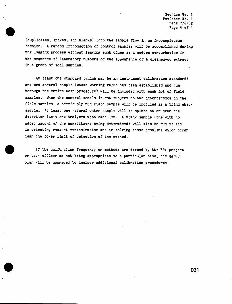
(duplicates, spikes, and blar.ks) into the sample flow in an inconspicuous fashion. A random introduction of control samples will be accomplished during the logging process without leaving such clues as a sudden perturbation in
the seouer.ee of laboratory numbers or the appearance of a clear.ea-up extract in a group of soil samples.
At least one standard (which may be an instrument calibration standard)
and one control sample (whose working value has been established and run through the entire test procedure) will be included with each lot of field
samples. When the control sample is not subject to the interference in the field samples, a previously run field sample will be included as a blind check
sample. At least one natural water sample will be spiked at or near the
detection limit and analyzed with each lot. A blank sample (one with no
added amount of the constituent being determined) will also be run to aid in detecting reagent contamination and ir. solving those problems which occur
near the lower limit of detection of the method.
. If the calibration frequency or methods are deemed by the SPA project
or task officer as not being appropriate to a particular task, the QA/3C
plan will be upgraded to include additional calibration procedures.
031

Section Mo. 3 Revision Mo. 1
Date 7/6/32 Page I'of 1
9.0 ANALYTICAL PROCEDURES
The following is a list of the analytical procedures typically used in
quantitatively analyzing samples from hazardous waste disposal sites. If the task reauired or EPA requested a substitution of analytical procedures this
would be done. If not, these methods listed below will be used.
Priority Pollutant Analysis
1. Organic Extractable Compounds
- semivolatiles and pesticides - EPA Method 625
- volatiles - EPA Method 624
2. Metals - EPA Method 600/4-79-020*
3. Cvaniae and Phenols - ESA Method 600/11-70-020*
Conventional Pollutants - EPA Method 600/4-79-020*
1. BOD - EPA Method 405.1 Bioassay
2. COD - EPA Method 410.3 Titrimetrie
3. T0C - EPA Method 4.5.1 Oxidation
4. pH - EPA Method 150.1 Electrometric
5. Oil and Grease - EPA Method 413.2 Spectophotometric
5. Ammonia - EPA Method 350.3 Potentiometric
7. Nitrate - EPA Method 352.1 Colorimetric
TCPD - EPA Method 513
RCRA Irritability - 40 CFR 261.21
RCBA Co-roslvltv - 40 CFR 251.22
RCRA Reactivity - 40 CFR 251.23
RCRA Extraction Procedure - 40 CFR 261.24
Herbicides: Methods for Benzidine, Chlorinated Organic Compounds, Psntachiorophenol, and Pesticides in Water and Wastewater, Sept. 1973.
•EPA Method 500/4-79-020: Methods for Chemical Analysis for Water and Wastes.

Section, 'to. 9 Revision Mo. i
Date 7/6/82 Page 1 of i
9.0 D4TA ANALYSIS, VALIDATION, AND REPORTING
For each major measurement parameter a brief description will be given for
• The data analysis scheme planned for collected data, including units and equations used to calculate values of measured parameters.
• Principle criteria to be used in validation of data integrity during collection and reporting
• Plans for treating outliers
• The data reporting scheme, including Identification of key individuals who will handle data in this scheme
• Criteria to be used to validate non-analytical measurements such as literature reviews/surveys, i.e.; spotchecks of data being gathered, Senior Management Review, etc.
All data will be reviewed and approved by JRB's laboratory QA/QC Monitor prior
to reporting. Standard Operating Procedures are included in Appendix A. Where
SOP's are not specifically mentioned, EPA SOP's will be used.

Section Mo. 10 Revision Mo. 1
Date 7/6/82 Page 1 of 2
10.0 IMTERMAL QUALITY COMTROL CHECKS
Ir. the analytical work plan, QC will be incorporated- ir. the form of OA
samples. This plan is reviewed by the QAO ana EPA for approval before the task begins.
Field quality control includes the collection of all blanks; typically
one blank per type parameter or media is necessary. Field blanks car.
include unused adsorbents, chemical solutions and unused filters. Field
QA/QC samples include duplicate ana/or field-spiked liquids or solids. In
the laboratory, the general scheme of each analysis type includes a set of
approoriate standards (generally U), a method blank, and one duplicate ana
one spike at a level of aporoximately 15t of a typical sample concentration
(including sample blanks). Reference material samples (S?MA) are analyzed
periodically, at least or.ce for each 10 batches. When spiking is not
practical, the percentage of duplicates will be doubled or multiple spikes will be analyzed.
Spiked field and lab samples will be treated in the exact manner-that
the samples are handled. Analysis of split sample lots are often included.
The exact scope of the QA/QC for any project will be determined dually by
the laboratory task manager and the QA/OC project officer, with approval of
the EPA and JR3 project/task manager's.
gfftWtigP.
Sufficient standards and blanks will be run to statistically establish
the lowest measurable signal and the lowest concentration which may be dis
tinguished from zero. The lowest calculated concentration will be reported
as the detection limit of the method, provided that at least one of the
spikes is below the calculated detection limit. The highest standard repre
sents the upper limit of reportable data. For the purposes of calculating
the detection limit, any nor.-linear portion at the upper concentration end
of the calibration curve will be discarded.
Section No. 10 Revision No- 1
Date 7/6/82 Page 2 of 2
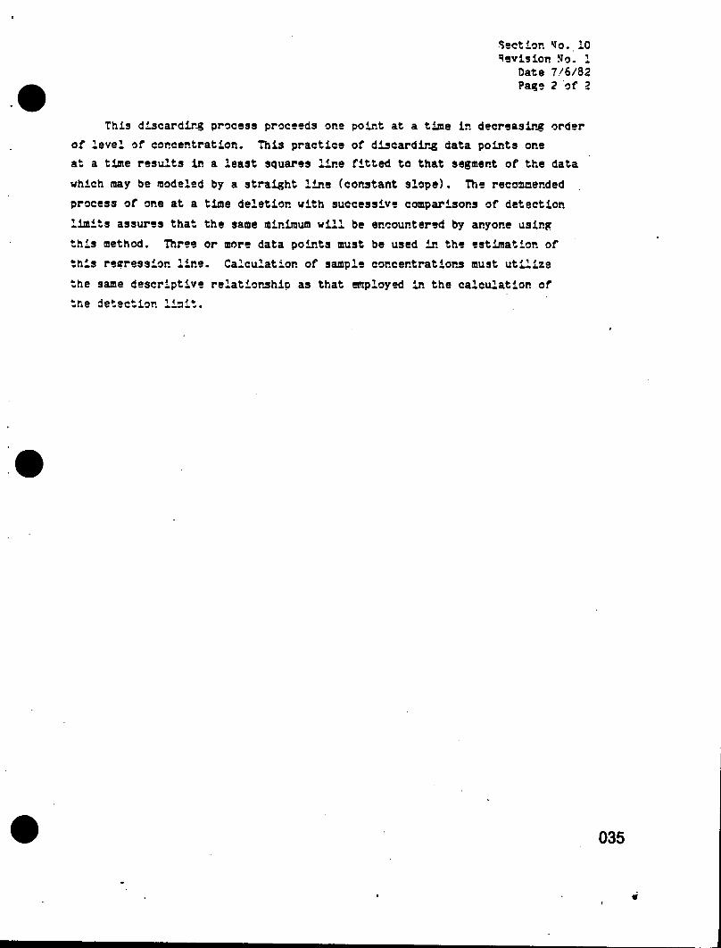
This discarding process proceeds one point at a time in decreasing order of level of concentration. This practice of discarding data points one at a time results in a least squares line fitted to that segment of the data
which may be modeled by a straight line (constant slope). The recommended
process of one at a time deletion with successive comparisons of detection
limits assures that the same minimum will be encountered by anyone using
this method. Three or more data points must be used in the estimation of
this regression line. Calculation of sample concentrations must utilize
the same descriptive relationship as that employed in the calculation of the detection limit.

Section. Mo. 11 Revision Mo. 1
Date 7/6/82 Page 1 of 3
11.0 PERFORMANCE AMD SYSTEM AUDITS
JR9 recognizes the need for regular and unscheduled system and performance
audits during the course of this contract. System audits will be performed
every six months and will encompass all activities being conducted on this task. Unscheduled system and performance audits will be conducted ones each
six months or more often if determined necessary by the QAO. The following
discusses specific details of each of these two audits.
System Anrt'f.
Or.ce every six months, the project OA/QC officer and the corporate QA
Director will conduct detailed systems audits across all active tasks on this contract. Specifically, record keeping practices will be reviewed, data
analysis techniques evaluated and adherence to quality control procedures
determined. The systems audit will also evaluate data management techniques
and particularly quality control procedures where computerized data management techniques are employed. Reports which have been generated since the
previous system audit will be randomly selected and data validation will be performed. At a minimum, this will include a spot check of references, veri
fication of any calculations, data validation of raw to hard copy and an assessment of conclusions drawn from the analysis.
The results of the system audit will be reported to the EPA project
officer, the JRB corporate QA Director and the project manager within two weeks following the completion of the audit.
Performance Audit
For each task which includes quantitative analysis as part of its work
plan, performance audits will be conductea. The first audit will be per
formed just prior to the initiation of the analytical program. During this
auait, the analytical techniques ar.d the experimental assign will be
evaluated by the project officer and a peer of the responsible party who

Section JJo. 11 Revision ?Jo. 1
Date 7/6/82 Page 2 of 1
will be performing the analysis (i.e., an experienced technologist who is not
partaking ir. the analysis will assist ir. the performance audit). Particular emphasis of this audit will be placed on the QA/QC plan and methodology which
have been written into the experimental design. Performance audits will also
be conducted on sampling activities including at the point Just prior to
the initiation of the sampling activity.
At a minimum, a second performance audit will be conducted after systems
are operational and are either generating or analyzing data. However, this
audit will be attempted at the earliest possible point in the measurement
program to minimize the effects if corrective action is warranted.
In sampling activities, the second performance audit will consist of
observing the sampling procedure and the occasional taking of a field sample
and blank which will be analyzed or evaluated immediately to detect if the
sampling procedures are causing contamination. If field measurement equipment is being used, such as a pH meter, another meter will be brought to
the site and simultaneous recordings will be taken.
•or monitorins laboratory measurements, a sample will periodically be
split and analyzed by another analyst on a different piece of equipment.
This analysis will be performed blind; the QA/OC officer will make the
comparison of results. Whenever possible, the performance audits will be
performed ir.-house. In cases where only one instrument of a particular
type exists, a determination will be made, along with the EPA project
officer, as to how the performance audit will be performed. Two options exist: the split sample will be sent to another laboratory for analysis
or the sample will be analyzed on a different day by a different analyst on the same piece of equipment or participates ir. EPA inter-calibration
effort ar.d/or EPA performance evaluation samples. Performance evaluation
samples will be utilized whenever possible. These samples will either
be provided by EPA or another government agency. Similarly, samples could
be purchased from HBS for evaluation purposes.

Section Mo. 11 Revision Mo. 1
Date 7'8/32
Ail results of the performance audit will he kept on record ar.a made available to the EPA project officer. Summary results of the performance
audit will be sent to the EPA project officer every six months.
038

Section Mo. 12 Revision Mo. 1
Date 7/6/82 Pace 1 of 1
12.0 PREVENTATIVE MAINTENANCE PROCEDURES AND SCHEDULES
To obtain reliable data, eouipment ar.d facilities must perform properly
at all times. Therefore, such eouipment and facilities shall undergo regular
inspection and preventative maintenance to guarantee that they are in good
working order. A pre-arranged plan and schedule using accepted and documented
procedures shall govern these activities. The specific QA Project Plan will
give only the most important occasions or instances of reouired preventative
maintenance. JRS's Standard Operating Procedures for preventative maintenance
are included in Appendix A.

Section No..13 Revision No. 1
Date 7/6/S2 Page 1 of 5
13-0 SPECIFIC PROCEDURES IN USE TO ROUTINELY ASSESS DATA PRECISION, ACCURACY AND COMPLETENESS
The following describe the methods that will be used on the TMS-III contract to assess accuracy, precision and completeness of data being
generated. The end of this section discusses how determination will be made
on non-analytical tasks.
AsswrasY
The accuracy of a method is expressed as the slope (b) of the least
scuares regression line of a plot of "measured" vs. "target" concentrations.
The regression line is based on a minimum of three concentrations. Data
are initially generated using standard samples, which provide the "best-case"
value of the slope. Natural samples will be analyzed similarly, and these
data will be added to the control chart. Values from sample sets will be added as they are generated.
Accuracy control charts will typically be generated as follows, unless otherwise directed by a project's requirements:
1. Sever, standard samples are spiked at the levels of 1DL, 10DL ana 100DL and analyzed.
2. The mean and standard deviation at each concentration level are calculated.
3. A plot of the "measured" vs. "target" concentrations is constructed. The least squares regression line of this plot is derived, and the mean and standard deviation of the slope are calculated.
The mean is the center line of the control chart. The standard aeviatior.(s) of the slope (over several days) is the basis of the warning and control limits. Warning limits are placed at the mean *,23. and control limits are the sear. +3s.
040
*»

Section Mo. 13 Revision No. 1
Date 7/6/32 Page 2 of 5
5. Data outside of the control lialts is not valid and subject to OA review. Similarly, sever, points on the same side of the central line constitute an errant situation, and QA review is needed. No data generated since the last valid control sample is submitted until the problem(s) is rectified.
5. With each sample lot, the slope is calculated and added to the control chart. The slope is then pooled with previous data to determine the values for control of the next sample set.
Prtsisior.
The measure used to estimate the precision of a method is the stan
dard error of the estimates (Sy,x) for the least square regression line of
"measured'' vs. "target" concentrations. For example, data from standard
waters are used first to determine the precision of the method, and then data from natural source water are used to determine the variability added
by the source (and the sampling). Distinct precision data is generated for specific narrow concentration ranges.
The primary role of this application is to characterize the precision
of any analysis method under specified conditions. This allows immediate
comparison of precision of different methods of analysis and/or different
results under the same method. Operating on data generated from standards
water will produce only one estimate of Sy,x, which is retained for refer
ence purposes. This precision estimate should alwavs be smaller than that found for any natural system, exceptions to this must be verified through
a careful cheek of all calculations. Operations with natural samples will theoretically produce as many Sy, x estimates as there are sample types. In
establishing a methodological approach, these several values should be pooled (for a given narrow concentration range) in accordance with the
following formula:
£S . frCyi-y)2 -b" (Zxj-x)^| y.» L "~2 -I
041

Section Mo. 13 'evisiop. Mo. 1
Date 7/6/82 Page 3 of 5
where
r. s number of replicates of each target concentration
N s number of target concentration.
This pooled estimate of the standard error is assumed to be the best estimate of the variability of the method. It is a sir.cle parameter estimate
of the precision of tne method and car. be compared with similarly derived
values. Future analyses should fail within these precision boundaries,
ana failure to do so flags the analyst, the task manager and the OA project officer.
Daily precision control charts will be used and constructed similarly
to the accuracy charts. For any given concentration, the mean and standard
deviation of the replicates will be calculated. The mean is the center
line, and warning and control iiaits are £2s and ,£33, respectively. Data
from each sample set will be pooled with previous data points to generate new
control values for the next set.
The following additional laboratory OA/QC procedures will be used to
assess accuracy and precision; these include linearity, recovery and use of standard additions.
i;r.?ar,tY
The measure of linearity between the spike level and the response
signal is represented by the correlation coefficient (Rxy). Accuracy and
precision test data should always reflect a positive value of Rxy equal to
or greater than 0.90. The laboratory has found that virtually all standards
addition data shows positive correlation measures in excess of +0.99. The
slope of the regression line is expected to be *1.0 after suitable correc
tions for scale differentials between spike and signal levels. Fxperi-
mer.tal values will deviate from this expected value, in a random Gaussian.
These deviations are assumed to be random Gaussian except when influenced
by insolutior. disturbances.

Section Mo. 13 Revision Mo. 1
Date 7/6/92 Page U of 5
Pqooverv
The recovery of the method for the analysis of environmental samples
is determined by adding a spike (T^, true value) of 50 ppb PC8 to the sample
selected earlier for replicate analysis. After the sample is analyzed and
the observed value (Dj.) is calculated, the recovery for the soike will be calculated as follows:
Pi = 100 (o i - Xi)/Ti
where is the percent recovery. If the sample was diluted due to the
addition of the spike, Xi is adjusted accordingly. After determining P^ for at least 15 spike results, calculate the mean percent recovery (P) ana
standard deviation (Sp) of the recovery as follows:
(2 ?,)/= i-L *
5 2 P? - ( 2 ? i-l 1 i-L ~ J
where
n = number of percent recovery values available.
If the percent recovery of the spike is not within the interval of? *, 3 Sp, the system aceuracv is out of control and the source of this systematic
error must be ider.tifiea and resolved before continuing with routine analysis.
At least one spiked sample will be analyzed along with each set of 20
samples or less that is analyzed at a giver, tine. These spiked data are
obtained for each parameter of interest. The recovery data of all spikea analyses are recorded and periodically (every 25 to 30 data points) the ,
accuracy criterion are revised, updated, and improved.
043
%

Section No. 13 Revision "o. 1
Date 7/6/32 Page 5 of 5
M-thcd of Standard Addition
When the results of an analysis by standard additions are plotted, any
observed departures from the predicted slope (equal to 1) may be taken as
estimates of inaccuracy. These inaccuracies are due to the inability of
the system to generate data which are independent of interferences. The
results of the sever, samples will be averaged as an estimate of the inaccur
acy of the method for such a population of samples.
Completeness
Completeness will be expressed as the percentage of the amount of valid data obtained compared to the amount of data expected. On the percent recovery
required to ensure data accuracy, unless specified in the work plan, a minimum •901 completeness will be the goal for the contract. For r.on-anaiytical tasks,
accuracy, precision and completeness will be assessed in a qualitative fashion. The following describes some ways in which these parameters could be determined.
• Accuracy: in determining accuracy in a data analysis task, the methodology used to perform the analysis will be evaluated for its ability to generate reliable and reproducible results. Data will be cross-cheeked and during systems audit will be traced to its origin to check the accuracy.
• Precision: if an analysis included developing a generalized model or developing scenarios as a means of performing a study, precision would be determined by comparing these outputs to a "known." situation. An example would be a technology assessment which included a set of conclusions from various data sources; these conclusions would be compared with a known test site and precision would be determined based on this comparison.
• Completeness will be determined by evaluating the sources studied versus the total universe of data available.

Section Mo. 14 Revision No. 1
Date 7/6/82 Pas? 1 of 1
14.0 CORRECTIVE ACTION
The need for corrective action comes from several sources: equipment
malfunction; failure of internal QA/OC checks; failure of performance or
system audits; and noncompliance with OA requirements. Each task in the experimental design will define what the acceptable limits are beyond which
corrective action must be implemented.
If measurement equipment or analytical methods fail QA./QC, the problem
will immediately be brought to the attention of the task manager and project
OA officer. If failure is due to eouipmer.t malfunction, the eouipmer.t will
be repaired, precision and accuracy will be reassessed, and the analysis will
be rerun.
If noncompliance is determined in the nor.analytical parts of the project,
the cause of this noncompliance will be assessed and a determination made
by the project OA officer as to how to rectify the problem. Corrective action
in this case can take several forms. Work will be reanalyzed or repeated
by the sane or different entity or a new work plan will be developed which refocuses the manner in which the work will be performed. All work which will
be performed as part of corrective action will be directlv supervised bv the JRS project officer and will be subjected to a rigorous evaluation by the
quality assurance officer prior to submittal to EPA.
In both cases of noncompliance, ail attempts will be made to reanalyze
ail affected parts of the analysis so that in the end, the product is not
affected by failure of QA requirements.
All incidents of OA failure and the corrective action tasks will be
reported immediately to the EPA project offficer.
045

Section No. 15 Revision No. 1
hate 7/6/92 Page 1 of I
15.0 QUALITY ASSURANCE REPORTS TO MANAGEMENT
Each task final report and technical outputs will include a section or statement that discusses and evaluates data quality and validity. At a
minimum, the following information will be covered in the progress reports and the final task report:
• Assessment of measurement data precision, accuracy, and completeness
• Documentation of QA/OC practices
• Performance audit results
• System audit results
• Significant OA Droblems and recommended solutions.
Eor the total TMS-III project, a report by tt\e JR3 OA Officer will be submitted ouarterly to the EPA Project Officer and the JRB Project Manager covering in general:
• Status of this project plan
• Status on the coverage of specific QA project plans under this contract
• Data quality assessments
• Significant QA probleos
• Results of system and performance audits.
046