draft permit permit significant amendment to. aquifer protection ... demonstrated pursuant to...
TRANSCRIPT

www.azdeq.gov
DRAFT PERMIT
SIGNIFICANT AMENDMENT TO AQUIFER PROTECTION PERMIT NO. P- 100329
PLACE ID 838, LTF 63316
1.0 AUTHORIZATION In compliance with the provisions of Arizona Revised Statutes (A.R.S.) Title 49, Chapter 2, Articles 1, 2 and 3, and Chapter 4, Arizona Administrative Code (A.A.C.) Title 18, Chapter 9, Articles 1 and 2, A. A. C. Title 18, Chapter 11, Article 4 and amendments thereto, and the conditions set forth in this permit, Pinto Valley Mining Corp., is hereby authorized to operate the discharging facilities located at the Pinto Valley Mine. The Pinto Valley Mine is located approximately 8 miles west of Miami, Arizona, in Gila County, over groundwater of the Salt River groundwater basin in Township 01 N, Ranges 13E and 14E, Section 30 of the Gila and Salt River Baseline and Meridian.
This permit becomes effective on the date of the Water Quality Division Director’s signature and Waste Programs Division Director’s signature and shall be valid for the life of the facility (operational, closure, and post-closure periods), unless suspended or revoked pursuant to A.A.C. R18-9-A213. The permittee shall construct, operate and maintain the permitted facilities:
1. Following all the conditions of this permit including the design and operational information documented or referenced below, and
2. Such that Aquifer Water Quality Standards (AWQS) are not violated at the applicable point(s) of compliance (POC) set forth below, or if an AWQS for a pollutant has been exceeded in an aquifer at the time of permit issuance, that no additional degradation of the aquifer relative to that pollutant, and as determined at the applicable POC, occurs as a result of the discharge from the facility.
1.1 Permittee Information Facility Name:
Pinto Valley Mine
Permittee:
Mailing Address:
Facility’s Street Address:
Pinto Valley Mining Corp.
P. O. Box 100 Miami, AZ 85539-0100
2911 N Forest Service Road 287 Miami, AZ 85539
Facility Contact: Manuel Estrada, General Manager
928-473-6214
Emergency Telephone Number: 928-473-6444 Latitude: 33° 24′ 33.0" North
Longitude: 110° 57′ 48.0" West
Legal Description: Township 01 N, Ranges 13E and 14E, Gila and Salt River Baseline and
Meridian.
1.2 Authorizing Signature
________________________________________ _______________________________________ Trevor Baggiore, Director Laura Malone, Director Water Quality Division Waste Programs Division Arizona Department of Environmental Quality Arizona Department of Environmental Quality Signed this _____day of _____________, 2016 Signed this _____day of _____________, 2016
THIS AMENDMENT SUPERSEDES ALL PREVIOUS AMENDMENTS

AQUIFER PROTECTION PERMIT APP NO. P-100329, LTF 63316
Page 2 of 73
2.0 SPECIFIC CONDITIONS [A.R.S. §§ 49-203(4), 49-241(A)]
2.1 Facility / Site Description [A.R.S. § 49-243(K)(8)] The Pinto Valley Mine includes an open pit copper and molybdenum mine and ore beneficiation facilities. The facility consists of ore crushing and flotation concentrating operations, dump leaching and solvent extraction/electrowinning (SX-EW) operations, tailings impoundments, waste rock dumps, process solution ponds, stormwater runoff ponds, process pipelines, ancillary maintenance operation facilities, a solid waste landfill and a wastewater treatment plant (WWTP). The discharging facilities regulated under this permit, listed below, were reviewed according to the design and operational plans approved by the Arizona Department of Environmental Quality (ADEQ) Aquifer Protection Permit (APP) Program. The original APP for this facility was issued in 1996. Millable ore is crushed and concentrated on-site. Copper concentrate is transported off-site to a third-party smelter. Molybdenum concentrates are containerized and shipped off-site. Low-grade ore is deposited in the dump leaching area referred to as Gold Gulch. Raffinate solutions consisting of weak sulfuric acid are sprayed over the low-grade ore. The resulting pregnant leach solution (PLS) is collected in a double-lined facility with a leak detection system and pumped to the SX-EW Plant (APP-exempt) where it is processed using an organic SX-EW process. Resulting cathode copper is shipped off-site for further refining. The site includes the following permitted discharging facilities:
FACILITY LATITUDE LONGITUDE DRAINAGE Low-grade Ore Leach Piles, Gold Gulch Drainage and PLS Facilities Raffinate Pond 33° 24′ 27" N 110° 59′ 20" W Whitman Draw Low-grade Ore Leaching Piles 33° 25′ 30" N 110° 58′ 10" W Gold Gulch Gold Gulch No. 1 PLS Pond 33° 24′ 59" N 110° 58′ 53" W Gold Gulch Gold Gulch No. 1A PLS Pond 33° 25′ 2" N 110° 58′ 58" W Gold Gulch Lower Gold Gulch Caisson 33° 25′ 07" N 110° 59′ 10" W Gold Gulch Gold Gulch Dam No. 2 and Reservoir 33° 25′ 29" N 110° 59′ 30" W Gold Gulch
Seepage/Stormwater Retention Facilities No. 1 Seepage Toe Drain and Caisson 33° 23′ 44" N 110° 59′ 00" W Miller Gulch
No. 1 Upper Basin 33° 23′ 41" N 110° 59′ 05" W Miller Gulch No. 1 Lower Basin 33° 23′ 41" N 110° 59′ 08" W Miller Gulch Upper Catchment Upper Pond 33° 23′ 43" N 110° 58′ 39" W Miller Gulch Upper Catchment Lower Pond 33° 23′ 41" N 110° 58′ 41" W Miller Gulch Upper Catchment Toe Drain 33° 23′ 37" N 110° 58′ 43" W Miller Gulch Upper Tule Pond 33° 23’16” N 110° 58’ 20” W Miller Gulch Lower Tule Pond 33° 23′ 18" N 110° 58′ 24" W Miller Gulch Lower Tule Caisson 33° 23′ 16" N 110° 58′ 23" W Miller Gulch North Pond 33° 23′ 52" N 110° 58′ 11" W Miller Gulch Peeples Pond 33° 23′ 50" N 110° 58′ 15" W Miller Gulch Southside Ditch 33° 23′ 24" N 110° 58′ 20" W Miller Gulch East Catchment & East Catchment Caisson 33° 25′ 21" N 110° 59′ 37" W Whitman Draw
Slack/Conklin Pond 33° 25′ 14" N 110° 59′ 45" W Whitman Draw No. 3 Seepage Caisson 33° 25′ 22" N 110° 59′ 52" W Whitman Draw West Catchment 33° 25′ 11" N 110° 59′ 53" W Whitman Draw Canyon Dam 33° 25′ 24" N 111° 00′ 00" W Whitman Draw Road Crossing Pond 33° 24′ 14" N 110° 58′ 46" W Gold Gulch Able Pond 33° 25′ 34" N 110° 59′ 45" W Gold Gulch Gold Gulch Final Catchment 33° 25′ 39" N 110° 59′ 36" W Gold Gulch Baker Pond 33° 25′ 45" N 110° 59′ 53" W Gold Gulch

AQUIFER PROTECTION PERMIT APP NO. P-100329, LTF 63316
Page 3 of 73
FACILITY LATITUDE LONGITUDE DRAINAGE Rosa′s Pond System 33° 27′ 19" N 110° 59′ 27" W Eastwater Canyon Cottonwood Canyon Reservoir 33° 23′ 23" N 110° 57′ 37" W Cottonwood
Canyon Cottonwood Seepage Caisson System 33° 23′ 04" N 110° 58′ 14" W Cottonwood
Canyon Tailings Impoundments Tailings Storage Facility No. 1 (TSF 1) (in post closure) 33° 23′ 55" N 110° 58′ 50" W Miller Gulch
No. 2 Tailings Storage Facility (TSF2) 33° 24′ 30" N 110° 59′ 05" W Whitman Draw
Tailings Storage Facility No. 3 (TSF3) 33° 25′ 00" N 110° 59′ 34" W Whitman Draw
Tailings Storage Facility No. 4 (TSF4) 33° 27′ 04" N 110° 59′ 00" W Eastwater Canyon
Yasin Impoundment 33° 26′ 59" N 110° 59′ 41" W Eastwater Canyon Rosa’s Pond Diversion Ditch 33° 27′ 20" N 110° 59′ 28" W Eastwater Canyon Road Pond/Lower Runoff Catchment Pond No. 1 33° 27′ 15" N 110° 59′ 40" W Eastwater Canyon
Charlie Pond/Lower Runoff Catchment Pond No. 2 33° 27′ 18" N 110° 59′ 50" W Eastwater Canyon
Waste Rock Dumps Northside Dump 9.1 33° 25′ 35" N 110° 58′ 47" W Gold Gulch Northside Dump 9.11 33° 25′ 23" N 110° 58′ 49" W Gold Gulch Northside Dump 9.12 33° 25′ 13" N 110° 58′ 44" W Gold Gulch Northside Dump 9.3 33° 24′ 25" N 110° 58′ 43" W Gold Gulch Southside Dump 13 33° 24′ 03" N 110° 58′ 18" W Cottonwood
Canyon Southside Dump 14 (in post closure) 33° 23′ 59" N 110° 58′ 36" W Miller Gulch
19 Dump 33° 23′ 36" N 110° 57′ 24" W Cottonwood Canyon
19.1 Dump 33° 23′ 49" N 110° 57′ 51" W Cottonwood Canyon
19 Extension Dump 33° 23′ 31" N 110° 57′ 04" W Cottonwood Canyon
North Barn Marginal Dump 33°24’17.77”N 110°58’37.41”W Gold Gulch Castle Dome Marginal Dump 33°24’28.70”N 110°57’33.52”W Open Pit Main Dump 33°25’22.64”N 110°58’00.65”W Gold Gulch Miscellaneous Facilities Open Pit 33º 24' 37" N 110° 57' 7" W N/A Concentrator 33° 23' 37" N 110° 57' 57" W Miller Gulch Wastewater Treatment Plant 33º 23' 30" N 110º 58' 17"W Tule Tank Solid Waste Landfill 33º 24' 19" N 110º 58’ 41" W N/A
Annual Registration Fee [A.R.S. § 49-242 and A.A.C. R18-14-104] The Annual Registration Fee for this permit is established by A.R.S. § 49-242 and is payable to ADEQ each year. The design flow is 22,464,000 gallons per day (gpd). The permittee shall notify ADEQ of any change in the facility contact information according to Section 2.7.7. Financial Capability [A.R.S. § 49-243(N) and A.A.C. R18-9-A203] The permittee has demonstrated financial capability under A.R.S. § 49-243(N) and A.A.C. R18-9-A203. The permittee shall maintain financial capability throughout the life of the facility. The estimated closure and post-closure cost is $63,051,344. The financial assurance mechanism was demonstrated pursuant to A.A.C. R18-9-A203.C.2 through a Performance Surety Bond.

AQUIFER PROTECTION PERMIT APP NO. P-100329, LTF 63316
Page 4 of 73
2.2 Best Available Demonstrated Control Technology [A.R.S. § 49-243(B) and A.A.C. R18-9-A202(A)(5)] Facilities regulated by this permit shall be designed, constructed, operated, and maintained to meet requirements specified by A.R.S. §49-243(B) and A.A.C. R18-9-A202(A)(5). The Pinto Valley Mine shall rely on the demonstrated passive containment capture zone (PCCZ), operational, hydrologic, and engineering controls to demonstrate BADCT as prescribed under this section. The facilities not relying on the PCCZ shall demonstrate BADCT as prescribed by this section. The permittee is authorized to operate the discharging facilities listed in Section 2.1 and detailed below. 2.2.1 Engineering Design
None of the facilities listed in this permit rely on the PCCZ for BADCT because they are outside the sink area; however monitoring of the PCCZ shall be conducted under this permit. The pit is dewatered by numerous vertical wells and barge pumps. Various catchments and associated diversion ditches prevent stormwater runoff from the surrounding hillsides from impacting the south and northeast areas of the wall slopes of the open pit. While the open pit is not considered an APP-discharging facility, this permit authorizes storing stormwater and/or process water in the open pit during operations and temporary cessation. BADCT for the pit shall consist of maintaining the pit as containment by preventing the water level from exceeding an elevation of 3,450 feet above mean sea level (amsl) except for brief periods of time during emergency situations. The exception for emergency situations is not to exceed 30 days in length without written approval of continuation by ADEQ. The stored water may be reclaimed to the extent practicable or allowed to evaporate if uses for it cannot be found. Ponds G, H, J, K and L collect stormwater and are exempt from regulation as surface impoundments pursuant to A.R.S. §49-250(B)(10). These ponds intercept stormwater runoff from adjacent watersheds to prevent water from flowing into the pit. Stormwater from these ponds can be piped to Cottonwood Canyon Reservoir.
2.2.1.1 Low-grade Ore Leaching Piles, Gold Gulch Drainage and PLS Facilities
The Gold Gulch No. 1 PLS Pond, Gold Gulch No. 1A PLS Pond, and the North and south Spillways are all part of the overall Gold Gulch Drainage Facility. The system is designed for recovery of PLS from the low-grade ore leach piles, collection of PLS and conveyance of PLS to the SX-EW Plant. The North and South Spillways shall consist of a series of pumps, leaching piles, collection ponds, dams, and ditches designed to collect and recycle PLS and stormwater runoff. 2.2.1.1.1 Raffinate Pond
The Raffinate Pond is located south of and adjacent to the SX-EW Plant. This pond was constructed by excavating into underlying limestone and was lined with a 6-inch low-permeability clay-soil-cement mixture that is compatible with the raffinate (Golder, 1998). The permeability of the liner was 1 x 10⁻⁶ centimeters per second (cm/sec) or less (Golder, 1998). The acidic solution (raffinate) from the SX-EW Plant is brought to the proper pH range by adding sulfuric acid before discharging to the Raffinate Pond. The raffinate is then pumped and applied to the Low-grade Ore Leaching Piles. The storage capacity is 23.0 acre-feet. The impoundment is designed and maintained so that the underlying rocks provide neutralization of normal seepage through the clay-soil-cement liner and for capture of seepage at APP-regulated facilities located downgradient to ensure that AWQS are not violated at a POC. Site-specific characteristics for this facility are described further in Section 2.2.2 of this permit. The facility is regularly inspected and maintained. Piping for PLS and raffinate solutions between the SX-EW Plant and the Low-grade Ore Leaching Piles was constructed of raffinate-compatible, high-density polyethylene (HDPE) and stainless steel to eliminate the potential for corrosion.

AQUIFER PROTECTION PERMIT APP NO. P-100329, LTF 63316
Page 5 of 73
2.2.1.1.2 Low-grade Ore Leaching Piles
During the leaching process, copper shall be extracted from the rock by passing an acidic solution (raffinate) from the Raffinate Pond through the leach piles. PLS from the Low-grade Ore Leaching Piles shall be collected in the Gold Gulch No. 1 and No. 1A PLS Ponds. BADCT components shall include seepage detection and collection systems, collection ponds and ditches, stormwater controls, and contouring and covering at closure, as well as use of site-specific characteristics. Site-specific characteristics for this facility are described further in Section 2.2.2 of this permit.
2.2.1.1.3 Gold Gulch PLS Ponds Two ponds collect PLS from the Low-grade Ore Leaching Piles: Gold Gulch No. 1 and Gold Gulch No. 1A. Two spillways from Gold Gulch No. 1 to Gold Gulch No. 1A act as an elevation control, preventing overtopping and freeboard exceedances. Gold Gulch No. 1 PLS Pond was located approximately 3,000 feet west of the open pit. It was constructed between 1975 and 1976 and was an existing structure at the time of permitting. Gold Gulch No. 1 PLS Pond was designed to capture PLS produced in the Low-grade Ore Leaching Piles as it flows to the head of Gold Gulch from beneath the piles. It was lined with compacted low-permeability materials with an estimated hydraulic conductivity of 1x 10⁻³ cm/sec or less and served as a sedimentation basin for settling of sediment prior to flow of PLS to Gold Gulch No. 1A. The pond was largely filled with 2-inch to 6-inch drainage material (quartzite) and covered with a 60-foot high buttress in 2007. Gold Gulch No.1 PLS Pond also collected stormwater runoff from the immediate vicinity of the PLS pond. PLS now flows through the former Gold Gulch No. 1 PLS Pond to Gold Gulch No. 1A PLS Pond. From there, PLS is pumped to the SX-EW Plant for recovery of copper. Stormwater management practices shall route stormwater runoff to Gold Gulch Dam No. 2 and Reservoir. Gold Gulch No. 1A PLS Pond receives PLS from Gold Gulch No. 1 PLS Pond from one of two spillways: the North Spillway and the South spillway pipe. Gold Gulch No. 1A PLS Pond is double-lined with geomembrane and includes a leak collection and recovery system (LCRS). The LCRS is monitored in accordance with Section 4.1, Table 4.1-1 and Section 2.5 of this permit. The capacity of Gold Gulch No. 1A PLS Pond shall be designed and maintained per BADCT criteria to eliminate the possibility of overflow. The holding capacity of this pond is approximately 423 acre-feet with 4.25 feet of freeboard. The pond shall be operated and maintained to prevent overtopping or berm breaches. In the event of an emergency, solution feed shall be diverted to the SX-EW Plant to prevent overflow. Design of this pond includes the Lower Gold Gulch Caisson, a concrete sump that collects PLS for pumpage back to the SX-EW Plant. The design of Gold Gulch No. 1A PLS Pond was based on flows to the SX-EW Plant. The impoundment employs an under-drain cutoff trench keyed into bedrock to capture any PLS migrating under the impoundment. This cut off trench is used to prevent flow to the underlying bedrock aquifer. These facilities are operated and inspected
AQUIFER PROTECTION PERMIT APP NO. P-100329, LTF 63316
Page 6 of 73
according to the requirements in Section 4.1, Table 4.1-4. The South Spillway between the two PLS ponds is a 36-inch-diameter, HDPE pipe installed at a 1.0 percent grade. The higher elevation is at the inlet in Gold Gulch No. 1 PLS Pond and the lower elevation is at the discharge into Gold Gulch No. 1A PLS Pond. The materials used in spillway construction include controlled low-strength material, HDPE geomembrane liner material, a geonet drainage layer, and HDPE large-diameter profile wall non-pressure pipe. The South Spillway culvert pipe shall be operated such that the solution surface at the pipe inlet for normal operation conditions shall be maintained to an elevation no greater than 1 foot below the existing spillway invert elevation of 3,525.5 feet amsl.
2.2.1.1.4 Gold Gulch Stormwater Containment Gold Gulch stormwater shall be contained by Gold Gulch Dam No. 2 and Reservoir, which retain stormwater from Gold Gulch and the waste rock dumps. The dam was built in 1982. The dam shall be maintained as a rock-filled embankment approximately 100 feet high with a low-permeability clay core and a 3-foot-thick transition zone of tailings sand. The dam shall be 413 feet long with a crest width of 20 feet with a grout curtain to control seepage. The dam shall be designed and maintained to retain 206 acre-feet of water. Water collected behind the dam is pumped to the mill process water system for reuse via Tank 16 (APP-exempt), Gold Gulch Dam No. 2 and Reservoir, TSF4 via the No. 4 Tailings Pipeline, or the Raffinate Pond. All seepage/stormwater retention facilities related to APP-regulated facilities shall at a minimum be so designed, constructed, and operated to contain the direct precipitation plus watershed runoff from the 100-year, 24-hour storm event plus the normal operating volumes.
2.2.1.2 Seepage/Stormwater Retention Facilities All seepage/stormwater retention facilities for APP-regulated facilities shall be, at a minimum, designed, constructed, and operated to contain the contact/impacted runoff from the 100-year, 24-hour storm event plus the normal operating volumes or to manage the maximum amount of runoff produced during 5 consecutive days of a MSE whichever is larger, including 2 feet of freeboard. Each facility has been designed and shall be maintained to manage runoff from the 100-year, 24-hour storm event plus the normal operating volumes, in addition to freeboard requirements. Pumping equipment and backup power sources shall be maintained where necessary for use in controlling stormwater runoff and recycle it to the process water control system. These facilities shall be operated and inspected according to the requirements in Table 4.1-4, Section 4.1. 2.2.1.2.1 No. 1 Seepage Toe Drain and Caisson
The No. 1 Seepage Toe Drain was constructed along the southwestern base of the TSF1 dam and consists of coarse rock emplaced in a 4-foot-deep, cobble-lined ditch. Commingled tailings seepage and stormwater runoff from TSF1 shall be collected and conveyed to the No. 1 Seepage Caisson. The bottom of the ditch is lined with fine tailings with an estimated permeability of 1 x 10⁻³ cm/sec or less to limit infiltration. The slope of the drain shall be maintained to prevent water from ponding in the bottom of the ditch. The Caisson consists of a rock-filled basin with a 4-foot-diameter, perforated, concrete caisson emplaced vertically approximately 30 feet into the ground. Water collected in the Caisson shall be pumped to the Upper Catchment Sand Trap (APP-exempt); overflow from the Caisson shall be collected in the No. 1

AQUIFER PROTECTION PERMIT APP NO. P-100329, LTF 63316
Page 7 of 73
Upper Basin. The seepage shall be collected and returned to the mill process water system, which is equipped with redundant power. Inspections of the structure, pumps, and emergency power shall occur on a routine basis and in accordance with the requirements in Section 4.1, Table 4.1-6 of this permit.
2.2.1.2.2 No. 1 Upper Basin (No. 1 Seepage Pond) The No. 1 Upper Basin is an excavated basin in native soil at the southwest corner of TSF1. This basin shall receive and retain overflow from the No. 1 Toe Drain and No. 1 Seepage Caisson, and stormwater runoff from the southern face of the TSF1 dam via the Upper Catchment Toe Drain. The embankment and pond bottom were constructed of select compacted materials; accumulated fine sediment covers the bottom and embankment sides. The overflow/spillway shall consist of a 36-inch inner diameter steel pipe and a 10.5-inch inner diameter HDPE pipe serving as conveyance piping. Overflows shall be routed to the No. 1 Lower Basin or No. 1 Seepage Caisson or Upper Catchment Sand Tank (APP-exempt). The facility and related equipment shall be regularly inspected and maintained in accordance with requirements in Section 4.1, Table 4.1-4 of this permit. The capacity of the basin together with the overflow facilities shall provide storage in excess of the 100-year, 24-hour storm event. Water from this basin is recycled and reused by the mine mill water process system, and water reclamation was considered as a component of existing facility BADCT for this mine.
2.2.1.2.3 No. 1 Lower Basin (No. 1 Seepage Pond)
The No. 1 Lower Basin is a basin excavated in native soil and located below the No. 1 Upper Basin and separated from it by a roadway berm. The embankment and pond bottom were constructed of select compacted materials; accumulated fine sediment covers the bottom and embankment sides. The basin shall be maintained for use during unusual precipitation events. It receives seepage and stormwater runoff from the No. 1 Upper Basin. Water collected in the basin is pumped to the No. 1 Seepage Caisson or the Upper Catchment Sand Tank (APP-exempt). Permitted overflow discharges may report to the AZPDES Outfall 002 and Pinto Creek and these discharges are monitored in accordance with AZPDES Permit AZ0020401. The facility and related equipment are regularly inspected and maintained.
2.2.1.2.4 Upper Catchment Upper Pond The Upper Catchment Diversion Ditch (APP-exempt) starts at a point below the Mine Office Building along the east side of Forest Service Road 287 and discharges into Upper Catchment Upper Pond. The Upper Catchment Diversion Ditch is part of the Upper Catchment Collection and Pumping System and consists of a corrugated metal pipe culvert system that collects stormwater associated with the 100-year, 24-hour storm event and returns it to the Upper Catchment Upper Pond or Upper Catchment Lower Pond for return to the mill process water system for reuse as a part of BADCT for the Upper Catchment Upper Pond. The Upper Catchment Upper Pond is located east of the southern-most point of TSF1. This pond receives runoff flows from the Upper Catchment Diversion Ditch, seepage flows from the southern face of the TSF1 dam, flows from the Upper Catchment Sand and Holding Tanks (exempt from APP) during storm events that exceed tank capacity, and runoff from the Concentrator Area.

AQUIFER PROTECTION PERMIT APP NO. P-100329, LTF 63316
Page 8 of 73
The pond was excavated in native soil; the embankment was constructed from selected excavated materials, which were then compacted. The pond shall have an approximate storage capacity of 0.18 acre-ft, and serve as a sedimentation basin for the Upper Catchment Lower Pond (below), from which it is separated by an earthen berm with a 24-inch corrugated metal pipe that acts as an overflow outlet.
2.2.1.2.5 Upper Catchment Lower Pond
The Upper Catchment Lower Pond is located east of the southernmost point of TSF1 and is separated from the Upper Catchment Upper Pond by an earthen berm with a 24-inch corrugated metal pipe that acts as outlet for drainage to the Upper Catchment Toe Drain. The drainage is pumped through pipes into the Upper Catchment Holding Tank (APP-exempt) and then to the Upper Catchment Upper Pond. This impoundment was excavated in native soils and the bottom and sides of the embankment were constructed of compacted borrow material and lined with accumulated fine sediment with an estimated conductivity of 1 x 10⁻³ cm/sec or less. Water from the pond is recycled by pump back to the APP-exempt Upper Catchment Holding Tank and then returned to the mill process water system or pumped to Cottonwood Canyon Reservoir or Upper Tule Pond for storage. The pond shall have a storage capacity of approximately 14.5 acre-feet. Seepage and flow reaching the elevation of the metal outlet pipe shall be captured in a French drain system (the Upper Catchment Toe Drain). The facility is equipped with diesel engine-driven pumps for emergency use and the facility and pumps shall be regularly inspected and maintained.
2.2.1.2.6 Upper Catchment Toe Drain
The Upper Catchment Toe Drain is located at the base of the Upper Catchment Lower Pond and extends in a westerly direction. This French drain system consists of a 3,000-foot-long, 6-inch-diameter, buried, slotted HDPE pipe at the base of the Upper Catchment Lower Pond berm. The toe drain captures seepage and flows through the metal pipe from the Upper Catchment Lower Pond. This drain discharges to the No. 1 Upper Basin, where the water is reclaimed for use in the Concentrator via the mill process water system.
2.2.1.2.7 Upper Tule Pond Upper Tule Pond is located southwest of the Concentrator, west of and adjacent to the Forest Service Road 287. The pond was excavated into native soil; the bottom was compacted; and fine sediments accumulated on the bottom to provide a low-permeability bottom, with an estimated permeability of 1 x 10⁻³ cm/sec or less. Upper Tule Pond collects stormwater runoff from the Concentrator Area and South Truck Shop area (roof and concrete aprons) via the Southside Ditch and Mine Office area, pumped discharge from the Upper Catchment Lower Pond, seepage and stormwater runoff from the Cottonwood Tailings Impoundment, and pumped seepage from the Cottonwood Seepage Caisson System. Accumulated water in this pond is pumped by a floating barge-mounted pump to the mill process water system. Overflows from this Pond are directed to the Lower Tule Pond. The Upper Tule Pond shall have a storage capacity of 17.8 acre-feet. The storage and pumping capacity shall be sufficient to manage the 100-year, 24-hour storm event.
2.2.1.2.8 Lower Tule Pond
AQUIFER PROTECTION PERMIT APP NO. P-100329, LTF 63316
Page 9 of 73
Lower Tule Pond is located southwest of the Concentrator and northwest and adjacent to Upper Tule Pond. It was excavated into the native soil below and is separated from the Upper Tule Pond by an embankment constructed of compacted fill. The sides and bottom are lined with accumulated fine particulates. The Lower Tule Pond shall have a storage capacity of approximately 28.9 acre-feet and receives overflow from Upper Tule Pond. Inflows from the Upper Tule Pond consist of stormwater runoff, seepage from tailings impoundment, and treated wastewater from the wastewater treatment plant. Discharge from Lower Tule Pond is to Tule Holding Tank (APP-exempt). Lower Tule Pond is part of a closed-loop system and inflows to this Pond are returned to the mill process water system for water reclamation.
2.2.1.2.9 Lower Tule Caisson
The Lower Tule Caisson is located downstream of the Lower Tule Pond. The caisson is a vertically-emplaced pipe that intercepts and collects seepage from the Lower Tule Pond for pump back to the mill process water system for water reclamation. Seepage is pumped back to Lower Tule Pond by a submersible, level-actuated pump, with sufficient capacity to return all flow to Lower Tule Pond, where it is part of a closed-circuit system that returns all flows to the mill process water system.
2.2.1.2.10 North Pond
North Pond is located northwest of the Concentrator and is adjacent to the final tailings thickeners. North Pond shall have a 3-acre-feet storage capacity and collect stormwater runoff from the Concentrator Area and excess tailings that may flow out of the final tailing thickener feed distribution box. This pond was excavated in native soil with accumulated fine tailings providing a low permeability bottom. A compacted berm was constructed at the west side of the pond to separate it from Peeples Pond. Accumulated tailings shall periodically be pumped back to the thickeners and water pumped to the mill process water system or discharged to Peeples Pond. North Pond is a closed loop system. Pumps with a maximum capacity of 600 gpm shall be used and are installed at the North Pond. The combined pumping capacity of pumps (in gpm) shall exceed the normal expected inflow to this pond including flows associated with 100-year, 24-hour storm event. Portable pumps shall be available for use in emergency situations as a backup.
2.2.1.2.11 Peeples Pond
Peeples Pond is located west of North Pond and northwest of the final tailings thickeners. This pond collects process water and stormwater runoff from the Concentrator Area, and also receives overflow from North Pond. This water is captured and is returned to the mill circuit water system upstream of Peeples Pond. Peeples Pond was excavated into native soil below the mine access road and the excavation was lined with an engineered, compacted clay liner to reduce seepage. The estimated permeability is less than 1 x 10⁻³ cm/sec. The pond is equipped with three barge-mounted discharge pumps to return the water to the mill process water system. The pond shall have a storage capacity of 40.17 acre-feet, which is adequate to handle a 100-year, 24-hour storm event and contain it for 5 days. The capacity of the pumps shall exceed expected inflow rates to ensure that pump back capacity can stay ahead of normal inflow and flow associated with the 100-year, 24-hour storm event.
AQUIFER PROTECTION PERMIT APP NO. P-100329, LTF 63316
Page 10 of 73
2.2.1.2.12 Southside Ditch The Southside Ditch is located south of the South Truck Shop Facility (APP-exempt) and was excavated into native soil, with culverts used to pass flow under the roadway. The Southside Ditch collects stormwater runoff and process spillage from the Concentrator Area and South Truck Shop and directs it via a collection ditch located west of the Mine Office buildings into an existing pipe culvert that carries runoff south to Upper Tule Pond where water is pumped to the APP-exempt Tule Holding Tank and back to the mill process water system. The bottom of the Southside Ditch is partially formed from culvert, which reduces the potential for infiltration. The ditch shall have a carrying capacity sufficient to contain a maximum flow of approximately 4,000 gpm and shall be sloped to prevent ponding in the bottom of the ditch. Accumulated fine sediment in the ditch shall reduce the permeability in the base and side walls of the ditch to approximately 1 x 10⁻³ cm/sec or less to limits infiltration.
2.2.1.2.13 East Catchment and East Catchment Caisson
The East Catchment and East Catchment Caisson are located on the east side of TSF3 and collect stormwater runoff and seepage from it. East Catchment was excavated into the natural soil and the bottom and embankments were constructed of imported compacted fill, with accumulated fine particulates providing a low-permeability bottom to the pond of 1 x 10⁻³ cm/sec or less. The East Catchment Caisson shall allow fluid to be collected for pump back for use in water reclamation. The Caisson is installed within the East Catchment. The facility is a closed-circuit, with all inflows being pumped to the mill process water system and a downstream seepage collection system to capture any seepage. The storage capacity of the facility shall maintain a sufficient volume (5.52 acre feet) to contain the 100-year, 24-hour storm event and normal operating discharges.
2.2.1.2.14 Slack/Conklin Pond
Slack/Conklin Pond is located downstream and due north of the center of TSF3 dam and is between East Catchment and Canyon Dam. The pond was constructed by excavating down in native soil and the embankment shall be maintained as an engineered, permitted, jurisdictional dam fitted with a concrete spillway. Slack/Conklin Pond collects stormwater runoff and seepage from a small drainage area below TSF3, overflow and seepage from West Catchment, pumped discharge from No. 3 Caisson, and is an alternate collection point for water pumped from Canyon Dam. Commingled seepage and stormwater runoff discharge to Tank 16 on TSF3 decant pond, and overflow is captured by Canyon Dam. Seepage from Slack/Conklin Pond shall be collected in No. 3 Seepage Caisson. This pond shall have a storage capacity of 51.10 acre-feet. The capacity shall be sufficient to contain the 100-year, 24-hour storm event. The pond shall be equipped with sufficient pump back capacity to handle cumulative inflows.
2.2.1.2.15 No. 3 Seepage Caisson
The No. 3 Seepage Caisson is located west of and downstream of Slack/Conklin Pond. This vertically emplaced pipe shall collect seepage from the French drain system located below Slack/Conklin Pond. The seepage shall be pumped back to Slack/Conklin Pond by a submersible, level-actuated pump, which has sufficient capacity to return all flow to Slack/Conklin Pond. The pipe shall have a storage capacity of approximately 2,000 gallons. Minor seepage that might bypass the caisson shall be captured by Canyon Dam.
AQUIFER PROTECTION PERMIT APP NO. P-100329, LTF 63316
Page 11 of 73
2.2.1.2.16 West Catchment
West Catchment is located downstream of the westernmost portion of the No. 3 Tailings Impoundment dam. This retention pond shall capture stormwater runoff from the TSF3 dam face and from the header road located at the top of the dam. West Catchment was excavated into the natural soil and the embankment was constructed of imported compacted fill. The bottom of the facility is formed from compacted fill and accumulated fine sediment with an estimated low permeability of 1 x 10⁻³ cm/sec. A barge pump shall be used to pump discharge to Slack/Conklin Pond or Tank 16. The basin shall have a storage capacity of 7.90 acre-feet, augmented by gravity overflow to Slack/Conklin Pond, which can contain the 100-year, 24-hour storm event. The permittee shall perform frequent inspections, and periodically remove accumulated particulates from the bottom of the pond as needed to maintain storage capacity, and shall maintain the barge-mounted dewatering pump.
2.2.1.2.17 Canyon Dam
Canyon Dam is located approximately 1,000 feet west of and downstream of Slack/Conklin Pond. This dam is constructed into native soil with an embankment constructed of imported compacted fill. The bottom of the facility was also constructed from compacted fill and is lined with accumulated sediment. The dam shall be equipped with a concrete spillway that acts as an AZPDES outfall. The pond behind the dam collects stormwater runoff and seepage for the drainage area located west of the TSF3 and below Slack/Conklin Pond. A diversion ditch shall be located upstream and to the southwest of Canyon Dam to divert undisturbed stormwater runoff. This pond shall have an 8.56 acre-feet storage capacity, sufficient to contain the100-year, 24-hour storm event. The pumping capacity shall be sufficient to prevent overflow discharge during a 100-year, 24-hour storm event. Commingled stormwater runoff and seepage discharges shall be pumped to Slack/Conklin Pond or Tank 16; and overflow shall be directed to AZPDES Outfall 003.
2.2.1.2.18 Able Pond
Able Pond is located northwest of Gold Gulch Dam No. 2 and just west of TSF4 access road. It is a constructed impoundment located adjacent to the No. 4 Tailings Pipeline that is used to convey tailings from the Concentrator to TSF4. Able Pond was excavated into native soils. A berm was constructed from excavated spoils and native material. The bottom and berm were compacted so as to provide a low-permeability surface. The estimated permeability of this surface is 1 x 10⁻³ cm/sec or less. Able Pond shall collect and contain tailings in the event of an emergency that requires draining or of failure of the No. 4 Tailings Pipeline. Inflow to Able Pond shall only occur during emergency situations and discharge would include tailings decant water and stormwater runoff. Able Pond shall have a design storage capacity of 6.49 acre-feet. The capacity of Able Pond (6.49 acre-feet) shall be sufficient to contain the entire volume of the No. 4 Tailings Pipeline located upgradient of the pond. Decant water from this pond is pumped to Tank 16 for return to the mill process water system and solids are excavated for disposal as needed to maintain storage capacity.
2.2.1.2.19 Gold Gulch Final Catchment
Gold Gulch Final Catchment is located downgradient of Gold Gulch Dam No. 2 and Reservoir, and adjacent to the No. 4 Tailings Pipeline,

AQUIFER PROTECTION PERMIT APP NO. P-100329, LTF 63316
Page 12 of 73
which conveys tailings from the Concentrator to TSF4. The Gold Gulch Final Catchment was excavated into native soils. The berm was constructed from excavated soils and native material. The bottom and berm were compacted to provide a low-permeability surface and contained fine-grained solids reduce the permeability of the bottom. The estimated permeability of this surface is 1 x 10⁻³ cm/sec or less. Gold Gulch Final Catchment collects and contains tailings in the event of a failure of the No. 4 Tailings Pipeline or as a result of an emergency requiring draining the pipeline. The Gold Gulch Final Catchment has a storage capacity of 2.8 acre-feet. The capacity of 2.8 acre-feet shall be sufficient to contain the entire volume of the pipeline located upgradient of the pond for complete containment in the event of pipeline failure. Decant water from this catchment shall be pumped to Tank 16 for return to the mill process water system and solids shall be excavated for disposal as needed to maintain storage capacity.
2.2.1.2.20 Baker Pond
Baker Pond is located northwest of Able Pond and is a constructed impoundment located near the No. 4 Tailings Pipeline. Baker Pond is used for emergency tailings storage if tailings are released from the tailings pipeline during the few minutes it would take for detection of the failure. In the event of tailings release, the system is designed to collect tailings from the area between TSF4 and Baker Pond. Baker Pond was excavated into native soils and a berm was constructed from excavated soils and native material. The bottom and berm were compacted so as to provide a low-permeability layer to limit infiltration. The estimated permeability of materials in the base and berm is 1 x 10-
3 cm/sec or less. The storage capacity of Baker Pond is 20.01 acre-feet and shall be sufficient to contain the entire volume of the No. 4 Tailings Pipeline located upgradient of the pond and extending north to TSF4, so complete containment will occur. Water in Baker Pond shall be disposed through evaporation. Sediment shall be removed periodically as needed to maintain the pond’s storage and collection capacity.
2.2.1.2.21 Rosa’s Pond System
Rosa’s Pond System is located at the downstream toe of TSF4 dam near the center of the dam. The system consists of one evaporation pond excavated into the native ground, the bottom of which is highly impermeable. The estimated permeability of the pond base is 1 x 10⁻³ cm/sec or less. Rosa’s Pond System collects seepage and stormwater runoff from the face of TSF4 dam and the area below Yasin Impoundment, which is regulated by this permit as part of TSF4. Rosa’s Pond System shall be designed and maintained as a containment and evaporation area and is not equipped with a pumping system. The capacity of 2.85 acre-feet shall be sufficient to contain the 100-year, 24-hour storm event.
2.2.1.2.22 Cottonwood Canyon Reservoir
Cottonwood Canyon Reservoir is located southeast of the Concentrator on the northeast side of the Cottonwood Tailings Impoundment. It has a maximum height of 32 feet and is approximately 700 feet in length with an upstream face covered with rip rap and a downstream drainage blanket. This reservoir was constructed of tailings from downstream of the reservoir, with a drainage blanket of sand and gravel placed on the downstream portion of the dam to control seepage and reduce piping of the existing tailings. The upstream filter consists of silty sand and gravel material. The upstream face of the dam was covered with a riprap layer of cobbles and boulders ranging in size from 3 to 18 inches.
AQUIFER PROTECTION PERMIT APP NO. P-100329, LTF 63316
Page 13 of 73
Cottonwood Canyon Reservoir is the primary process water storage facility for Pinto Valley Mine and receives stormwater runoff, seepage, reclaimed water and process make-up water. A floating barge-mounted pump shall be used to deliver recycled water from the reservoir to the mill head tank. The reservoir storage capacity shall be 453.63 acre-feet based on a design discharge rate of up to 5,000 gpm. Accumulated fine-grained tailings have rendered the bottom of the reservoir relatively impermeable and infiltration that passes through the bottom of the reservoir shall be collected as seepage in the Cottonwood Seepage Caisson System. In extreme storm events, surface water may flow over the reservoir spillway onto the surface of the Cottonwood Tailings Impoundment to be captured in the Cottonwood Settling Basin. The Cottonwood Canyon Reservoir is a closed system.
2.2.1.2.23 Cottonwood Seepage Caisson System
The Cottonwood Seepage Caisson System is located at the western edge of Cottonwood Tailings Impoundment and consists of a collection tank, caisson, and transfer pump. The system collects seepage and stormwater runoff from within Cottonwood Tailings Impoundment and from the western face of the impoundment. The caisson is 22 feet deep, and the water level is maintained at 19 feet below surface. The collection tank is 4 feet deep and receives seepage water from a 4-inch diameter pipeline that connects with the decant tower located within the impoundment. Overflow from the collection tank flows to the caisson. Pumps within the caisson transfer water to Tule Holding Tank, where it is pumped to the mill process water system. The Cottonwood Seepage Caisson System is fully contained collection point that collects water to be reclaimed for use in the Concentrator. Pumps shall be of sufficient capacity to prevent the possibility of inadvertent release. In the event of overflow, the facility is permitted for release of water through AZPDES Outfall 004
2.2.1.3 Tailings Impoundments Tailings impoundments were constructed using the upstream construction method. Tailings shall be deposited in two active engineered tailings impoundments (TSF3 and TSF4) using cycloning and spigotting to separate the coarse portion of the tailings from the slimes. The coarse portion shall be used for dam construction. The slimes were used for lining the tailings decant ponds during the construction of the decant ponds and were used as low permeability liner material to decrease infiltration and seepage. This use of slimes is not an on-going operational method. Decant pond size shall be minimized by constant reclaiming and recycling of decant water to the process water control system. Beach widths shall be optimized to enhance dam stability. Dam stability shall be monitored using piezometers. These facilities shall be operated and inspected according to the requirements in Section 4.1, Table 4.1-4.
2.2.1.3.1 TSF1
TSF1 has been decommissioned and has not received tailings material since 1989. The closure work for this facility consisted of: re-grading the sloped areas, rock armoring on the faces of TSF1 and Southside Dump 14, placement of evapotranspiration cover on the top and faces, construction of stormwater diversion channels, and implementing re-vegetation. The facility remains in post-closure maintenance.
2.2.1.3.2 TSF2 TSF2 is located north of TSF1 and includes accumulated tailings and a

AQUIFER PROTECTION PERMIT APP NO. P-100329, LTF 63316
Page 14 of 73
former decant pond. Deposition of tailings in TSF2 was discontinued in 1989. Any seepage from TSF2 flows into TSF3 in the Gold Gulch drainage area.
2.2.1.3.3 TSF3
TSF3 is located north-northwest of TSF2 and is permitted to accept tailings from the flotation process at the concentrator. It consists of a tailings impoundment, a series of pumps, caissons, collection drains, ditches, ponds, and tanks designed to collect and recycle seepage and stormwater runoff from the face of TSF3 Dam. All stormwater runoff and seepage collected (in the nearby East Catchment and Caisson, Slack/Conklin Pond, West Catchment, No. 3 Seepage Caisson, and Canyon Dam) shall be returned to the mill process water system, except for overflow that is permitted through AZPDES Outfall 003. The facility shall be operated as a closed-circuit system that meets BADCT requirements. The facility components shall be regularly inspected and periodically maintained to ensure proper operation in accordance with the requirements of this permit.
2.2.1.3.4 TSF4
TSF4 is located approximately 4 miles north of the Concentrator in Eastwater Canyon and is permitted to accept tailings from the flotation process at the concentrator. The starter dam was originally constructed by the upstream method. The design consisted of an excavated dacite rock-fill embankment with a low-permeability cap on the upstream face. A 30-foot-thick layer of drain material was placed between the rock fill and soil cover of Gila Conglomerate with a 10-foot-thick layer of river run gravel placed on the Gila Conglomerate to act as a toe drain and shall be maintained to serve in this function. Tailings slimes were used to line the bottom of the impoundment to create a low-permeability base. Decant water is recycled to the mill process water system and seepage and stormwater runoff are directed to downstream intercept ponds and basins (Yasin Impoundment Rosa’s Pond System, and Lower Runoff Catchment Pond No. 1 [also called Road Pond] and Lower Runoff Catchment Pond No. 2 [also called Charlie Pond]), which have been upgraded to increase capture of seepage from the dam. In addition, operational engineering controls shall be used to reduce the size of the decant pond, therefore decreasing the seepage emanating from the pond. The dam face (below elevation 3,790 feet) has been reclaimed with a minimum 2-foot-thick soil cover, which is subsequently protected with 6 to 13 inches of rock armor, depending upon slope angle and locations. While re-vegetation activities are applied to reclaimed areas to enhance aesthetics and water uptake, the rock armor prevents erosion. Any discharging dam faces that are not reclaimed will be stabilized with tackifiers, re-vegetation, or equivalent techniques to prevent erosion. The Yasin Impoundment was excavated into the northwest face of the TSF4 dam and collects stormwater runoff from the face of the dam, as well as spills from the TSF4 Pumping Station, spilled tailings and gland seal pump drips which shall discharge to the concrete lined gland water sump (APP-exempt) and then through pipes to Yasin Impoundment for pumpage to TSF4 Dam. Yasin Impoundment is located on TSF4. The collected water is then pumped back to the mill process water system. Charlie and Road Ponds and the Rosa’s Diversion Ditch are all part of BADCT for TSF4 and collect and divert contact stormwater from the face of the tailings to downstream structures. These ponds evaporate stormwater received from TSF4. Stormwater run-on at TSF4 is collected and reused in mine processes. As long as stormwater run-on is allowed at this facility, pumps shall be

AQUIFER PROTECTION PERMIT APP NO. P-100329, LTF 63316
Page 15 of 73
maintained to be used in support of BADCT. In order to fill TSF4 to its maximum permitted elevation of 4,005 feet above mean sea level (amsl) and remain on patented land or land authorized by the US Forest Service for such use, TSF4 may require addition four boundary dams located on the east side of the facility. A separate Saddle Dam located on the west side of the PVM will be required. The dams would be constructed in a staged manner, beginning as early as 2016, and would maintain 5 feet of freeboard between the TSF4’s supernatant pool and the top of each boundary dam. The boundary dams were analyzed for static and pseudo-static slope stability and for seismic hazard and meet or exceeded the BADCT requirements for tailings impoundments. An acceptable seepage analysis was completed to assess the steady-state seepage condition and evaluate embankment stability for the maximum pool condition. The boundary dams are non-discharging facilities (structures). Boundary Dam 1 (BD1): BD1 will consist of engineered fill, upstream and downstream slopes of 2:1 (horizontal:vertical), and a crest maximum elevation of 4,005 feet amsl. Boundary Dam 2 (BD2): BD2 will consist of engineered fill, upstream and downstream slopes of 2:1, and a maximum crest elevation of 4,005 feet amsl. Boundary Dam 3 (BD3): BD3 will consist of engineered fill, upstream and downstream slopes of 2:1, and a maximum crest elevation of 4,005 feet amsl. Boundary Dam 4 (BD4): BD4 will consist of engineered fill, downstream slope of 2.5:1, upstream slope of 2:1, and a maximum crest elevation of 4,005 feet amsl. Saddle Dam: Saddle Dam will consist of engineered fill, downstream slope of 2.5:1, upstream slope of 2:1, and a maximum crest elevation of 4,005 feet amsl.
2.2.1.4 Waste Rock Dumps The waste rock dumps and associated runoff impoundments shall be operated and inspected according to Section 4.1, Table 4.1-4. Waste rock dumps at the facility fall into two categories: 1) those developed pre-APP and that are in use or 2) those that were part of the original APP application and have yet to be developed, but BADCT was approved at the time the original APP was issued. The permittee may test materials for inertness to determine whether the materials are exempt.
2.2.1.4.1 Northside Dump 9.1
The Northside Dumps are located north of Gold Gulch and are used to contain waste rock from the open pit. They include Northside Dump 9.1, 9.11, and 9.12, which are located west of the Low-grade Ore Leaching Piles, and Northside Dump 9.3, which is located south of Gold Gulch and west of the open pit. Inflows consist of stormwater and discharges of stormwater runoff. Seepage from these dumps is not known to occur. The potential for acid generation and attendant leaching of heavy metal constituents by percolating waters through the waste rock dumps to the underlying bedrock system is low, based on the results of the geochemical sampling and analyses which indicate that materials in the Northside dumps are non-acid forming (Hargis, 1995) (Schafer & Associates, 1995). Stormwater runoff from the 9.11,
AQUIFER PROTECTION PERMIT APP NO. P-100329, LTF 63316
Page 16 of 73
9.12, and 9.3 Dumps is contained by runoff diversion or collection facilities. Northside Dump 9.1 primarily overlies dacite and consists of approximately 680,000 tons of rock in equal mixtures of granodiorite, diabase, quartz monzonite, and altered limestone, with small quantities of Gila conglomerate, Whitetail conglomerate, granite porphyry, schist, and quartzite. Runoff from the 9.1 Dump shall follow natural drainages and terminate prior to reaching Pinto Creek. Stormwater intercept and diversion ditches shall be regularly inspected and cleaned.
2.2.1.4.2 Northside Dump 9.11
Northside Dump 9.11 consists of approximately 13.5 million tons of rock consisting mainly of quartz monzonite and diabase, with smaller amounts of granodiorite, granite porphyry, Whitetail conglomerate, Gila conglomerate, schist, and quartzite. It overlies Whitetail conglomerate and dacite.
2.2.1.4.3 Northside Dump 9.12
Northside Dump 9.12 consists of 560,000 tons of rock consisting mainly of quartz monzonite and Whitetail conglomerate, with smaller quantities of diabase, Gila conglomerate, quartzite, and altered limestone. It overlies Whitetail conglomerate and dacite.
2.2.1.4.4 Northside Dump 9.3
Northside Dump 9.3 consists of approximately 9 million tons of waste rock consisting mostly of diabase and Whitetail conglomerate, with additional granodiorite, schist, quartzite, basalt, altered limestone, and some tailings. This waste rock was placed above Gila conglomerate.
2.2.1.4.6 Southside Dump 13 The inactive Southside Dumps are located on the south side of the mine and are used to contain waste rock from the open pit. They include Southside Dump 13 and Southside Dump 14, which are located northwest of the Concentrator and southwest of the open pit and southeast of TSF1, and 19 Dump and 19.1 Dump, which are located south of Schist Hill, south of the open pit. The overall acid-forming potential of the Southside Dumps is considered to be moderate to low because of the composition of the rock types deposited there. Drainage from the Southside waste rock dumps shall be controlled and contained. Diversion ditches shall limit the amount of stormwater run-on to the dumps and direct runoff to collection ponds or other facilities for reclamation. No stormwater runoff from the waste rock dumps is discharged. The potential for acid generation and attendant leaching of heavy metal constituents by percolating waters within the waste rock dumps to the underlying bedrock system is low, based on the results of the geochemical sampling and analyses. Southside Dump 13 (6.9 acres) consists of approximately 1 million tons of rock composed primarily of diabase and quartz monzonite, with smaller amounts of granodiorite, Gila conglomerate, Whitetail conglomerate, and basalt. It overlies Gila conglomerate and basalt.
2.2.1.4.7 Southside Dump 14
The Southside Dump 14 has been decommissioned and was closed as part of TSF1 closure. The area where the Southside Dump 14 existed overlaid TSF1 and the majority of the material was used in constructing the cover layer for TSF1. The closure work for this facility consisted

AQUIFER PROTECTION PERMIT APP NO. P-100329, LTF 63316
Page 17 of 73
of: re-grading the sloped areas, rock armoring on the faces of TSF1 and Southside Dump 14, placement of evapotranspiration cover on the top and faces, construction of stormwater diversion channels, and implementing re-vegetation. The facility remains in post-closure maintenance.
2.2.1.4.8 19 Dump The 19 Dump has a disposal capacity of 101.3 acres and consists of approximately 27 million tons of rock composed mostly of schist. The dump overlies granite. Stormwater runoff from 19 Dump shall flow to Cottonwood Canyon Reservoir.
2.2.1.4.9 19.1 Dump
The 19.1 Dump has a disposal capacity of 1.3 acres and is a small dump consisting of less than one million tons of waste rock comprised of schist. It overlies schist. Stormwater runoff from 19.1 Dump shall flow into the open pit.
2.2.1.4.10 Extension Dump
The 19 Extension Dump shall be located south of the existing 19 Dump in Cottonwood Canyon and shall be used to contain waste rock from the open pit. It shall consist of approximately 19 million tons of waste rock and will cover 156 acres. Stormwater runoff from the Cottonwood Canyon drainage area will be discharged to the Cottonwood Canyon Reservoir, where it shall be fully captured and returned to the mill process water system. No direct releases to the aquifer will occur. The dump shall be designed, constructed, and operated in accordance with the requirements of the approved BADCT design. It will be constructed exclusively from non acid-forming schist and will be constructed partially on the existing 19 Dump and will bridge the upper reaches of Cottonwood Canyon.
2.2.1.4.12 North Barn Marginal Dump (NBMD) The NBMD will be located along the west-southwest side of the PVM Open Pit and contain approximately 11,000,000 tons of marginal-grade waste rock on approximately 36 acres of disturbed ground and existing waste rock dump material. The NBMD was analyzed for both static and dynamic loading conditions and meet the BADCT (Appendix E) factor of safety (FOS) design criteria. The build-out height of the NBMD shall be no greater than 257 feet at a crest elevation of 4,175 feet amsl. Geochemical modeling along with static tests indicated that there is moderate potential for the NBMD to generate acidic rock drainage, however the geologic formations located below the NBMD will buffer (neutralize) the potential discharge from the marginal material.
2.2.1.4.13 Castle Dome Marginal Dump (CDMD) The CDMD will be located adjacent to the south edge of the PVM Open Pit and contain approximately 10,000,000 tons of marginal-grade waste rock on 45 acres, of which 15 acres will be on undisturbed ground, 15 acres on disturbed ground (historic mill site), and approximately 15 acres will be outside the area of the mill site. The Castle Dome mill site is not part of BADCT for a discharging facility. The CDMD was analyzed for both static and dynamic loading conditions and meets the BADCT (Appendix E) factor of safety (FOS) design criteria. The build-out height of the CDMD shall be no greater than 360 feet at a crest elevation of 4,370 feet amsl. Geochemical modeling along with static tests indicated that there is potential for the CDMD to generate acidic rock drainage, which will discharge to the Open Pit (hydrologic sink).

AQUIFER PROTECTION PERMIT APP NO. P-100329, LTF 63316
Page 18 of 73
2.2.1.4.14 Main Dump
The Main Dump, totaling approximately 342 acres of waste rock, will be located on a portion of the retired Low-grade Ore Leaching Piles (LGLP) north of the Open Pit. The total volume of material to be placed on the Main Dump will be approximately 142,760,000 million tons. This facility will occupy the footprints of the formerly permitted but unbuilt APP facilities namely: Gold Gulch West Dump (GGWD), Gold Gulch East Dump (GGED), and the LGLP expansion consisting of additional lifts of leach ore material on approximately 170 acres on the northwestern portion of the existing LGLP. While a majority of the Main Dump will be located on the retired leach pile, about 27.3 acres of the eastern portion will be located on undisturbed ground. The eastern portion of the dump that will be located on undisturbed land will be underlain by limestone and dacite which have hydraulic conductivity values ranging from 2 x 10⁻³ to 2 x 10⁻⁶ cm/sec. The previously permitted Gold Gulch dumps were analyzed for both static and dynamic loading conditions and meet the BADCT factor of safety (FOS) design criteria.
There is no change to the stability assessment for the waste rock in Main Dump, as the design heights and slopes are designed to the same stability criteria as for the prior GGDs and leach dump material. Slope angles for the surface of the Main Dump vary slightly over the facility but range from 29 to 30 degrees as was previously designed for the GGDs and the leach material. The Main Dump design incorporates design heights that are not substantially different than used in 2014. The top bench of western portion of the Main Dump, for example, is 6 feet higher than the bench height for the “New Low-Grade Leach Material”. The top benches of the central and eastern portion of the Main Dump are 14 feet lower than the top benches of the GGDs. The maximum crest elevation of the Main Dump will vary from approximately 4,444 feet near the west end, to approximately 4,804 feet near the east end of the dump.
2.2.1.5 Concentrator Area
The Concentrator Area consists of several related structures and facilities used to recover copper-rich and molybdenum-rich concentrates from sulfide ore. These facilities include primary and secondary crushing, and intermediate ore storage; the main Concentrator where grinding and froth flotation are performed; concentrated and tailings thickeners; various storage tanks, which are exempt from APP used for concentrate and water; reagent preparation; and concentrate handling. Runoff from the Concentrator Area is directed to APP-regulated storage facilities because of the presence of intermediate ore stockpiles. The concentrate facility is located in above ground tanks and is exempt from APP regulation. Runoff from the Concentrator Area will be contained by downstream seepage/stormwater retention facilities as described in the approved plans submitted with the original APP application. The run-off impoundments associated with the Concentrator Area are listed in this permit as discharging facilities and shall be operated and inspected according to Section 4.1, Table 4.1-6.

AQUIFER PROTECTION PERMIT APP NO. P-100329, LTF 63316
Page 19 of 73
2.2.1.6 Solid Waste Landfill Between 1 and 2 feet of cover shall be placed over solid waste materials when the landfill is in active use. The facility shall be inspected after significant storm events to ensure stormwater runoff control features are maintained to prevent stormwater ponding. A maximum of 60,000 cubic yards of Northwest Study Area (NWSA) soils from the remediation site near Superior, Arizona, were used as landfill daily cover at the Pinto Valley Mine. Placement of the soil was restricted as follows:
1. Stockpiled soils shall remain within the northern one-third (1/3) of the footprint
of the Solid Waste Landfill. 2. The stockpiled NWSA soils were used as daily cover at the Solid Waste
Landfill as needed, but must remain protected by the same stormwater run-on and runoff controls that are in effect for the landfill. Berms shall be used to control and direct stormwater run-on/runoff in order to minimize infiltration and erosion, and eliminate ponding on the disposal area and the NWSA soil stockpile.
2.2.1.7 Wastewater Treatment Plant
Sewage from most buildings in the main plant area is delivered by gravity to the WWTP via a subgrade pipeline system. The WWTP is a factory built, Smith & Loveless Model 20-B-25 Oxigest extended aeration-type sewage treatment plant that consists of primary and secondary treatment. The primary filtration system removes large solids and trash from the system. After primary filtration, the effluent is gravity-fed to a secondary treatment system consisting of an aerobic degradation system. The effluent is treated by injecting air into the receiving tank to increase the oxygen content of the incoming effluent and to provide agitation of the tank. The WWTP is designed to meet the treatment performance criteria for existing facilities as specified in A.A.C. R18-9-B205.
2.2.1.8 Open Pit The open pit is located northeast of the Concentrator in the Gold Gulch drainage area and is the source of ore and waste rock. The Pinto Valley ore body contains chalcopyrite, pyrite, and minor molybdenite as the only significant primary sulfide minerals and is hosted in the Lost Gulch quartz monzonite. Although there was mining between 1943 and 1953, development of the current mining operation began in 1972. In 1995, the open pit covered approximately 1,100 acres (7,300 ft by 6,500 ft) and was approximately 700 feet deep. The pit is dewatered by numerous vertical wells and pumps. Various catchments and associated diversion ditches prevent stormwater runoff from the surrounding hillsides from impacting the south and northeast areas of the wall slopes of the open pit. This permit authorizes storing stormwater and/or process water in the open pit during operations and temporary cessation. BADCT for the pit shall consist of maintaining the pit as containment by preventing the water level from exceeding an elevation of 3,450 feet amsl except for brief periods of time during emergency situations. The exception for emergency situations is not to exceed 30 days in length without written pre-approval of ADEQ. The stored water may be reclaimed to the extent practicable or allowed to evaporate if uses for it cannot be found. Ponds G, H, J, K and L collect stormwater and are exempt from regulation as surface impoundments pursuant to A.R.S. §49-250(B)(10), but are a part of BADCT for the open pit. These ponds intercept stormwater runoff from adjacent watersheds to prevent water from flowing into the pit. Stormwater from these ponds is piped to Cottonwood Canyon Reservoir.

AQUIFER PROTECTION PERMIT APP NO. P-100329, LTF 63316
Page 20 of 73
2.2.2 Site-specific Characteristics Site-specific characteristics that were used in the BADCT demonstration are included in this section. The depth to groundwater beneath this facility ranges from artesian conditions in APP-6 to 405 feet below ground surface (bgs) in APP-1Br, but varies seasonally. Groundwater modeling results have been presented to ADEQ to demonstrate that the open pit constitutes a hydrologic sink. Modeling (Hargis & Associates, 1995) was used as the basis for the BADCT demonstration for containment in the pit. At present the Castle Dome Marginal Dump is the only regulated facility that relies on the hydrologic sink as part of BADCT. Monitoring, inspection, and reporting requirements associated with the pit lake and hydrologic sink shall be conducted in accordance with Table 4.1-4 of this permit. 2.2.2.1 Low-grade Ore Leach Piles, Gold Gulch Drainage and PLS Facilities
The following sections describe the site-specific BADCT for discharging facilities, if used in the BADCT demonstration. 2.2.2.1.1 Raffinate Pond
The soil cement-lined Raffinate Pond was constructed by excavation into an underlying limestone formation, which has a buffering capacity to neutralize acidic seepage, as demonstrated by column testing (Hargis & Associates, 1997). This neutralization capacity shall be used to minimize infiltration of acidic solution and was considered and approved as part of BADCT design. If over time the neutralization potential of the underlying system is exceeded, BADCT upgrades may be required for this facility.
2.2.2.1.2 Low-grade Ore Leaching Piles
The bedrock underlying the low grade leaching piles has an estimated hydraulic conductivity of less than 1 x 10⁻³ cm/sec, as demonstrated through a water budget analysis and testing (Hargis & Associates, 1995). In addition, upward vertical gradients have been observed in wells in this area and there are springs located near-by (Hargis & Associates, 1995). The low hydraulic conductivity of the bedrock system that underlies the Low-grade Ore Leaching Piles and the presence of upward hydraulic gradients and springs in the area were considered as part of BADCT design for this facility. These characteristics shall be used to minimize the opportunity for infiltration of PLS into the underlying rocks.
2.2.2.1.3 Gold Gulch PLS Ponds
Gold Gulch No. 1 PLS Pond was constructed using on-site materials containing sufficient fines to provide a compacted, low permeability embankment which shall serve as a sedimentation pond prior to PLS conveyance to Gold Gulch No. 1A PLS Pond to reduce fines in PLS solutions pumping back for extraction. The estimated permeability of these materials is 1 x 10⁻³ cm/sec or less and this characteristic and the fact that PLS No. 1 was an existing facility at the time of permitting were used as part of the BADCT demonstration for this facility. These characteristics shall be used to prevent loss and migration of PLS to the bedrock aquifer that underlies the impoundment.
2.2.2.1.4 Stormwater Containment at Gold Gulch
No site-specific characteristics were used in support of BADCT for these facilities.
2.2.2.2 Seepage/Stormwater Retention Facilities
No site-specific characteristics were used in support of BADCT for these facilities.

AQUIFER PROTECTION PERMIT APP NO. P-100329, LTF 63316
Page 21 of 73
2.2.2.3 Tailings Storage Facilities
Site-specific conditions shall be used to minimize the opportunity for acid-rock drainage production or accumulation and monitoring and characterization shall be performed in accordance with Sections 2.3.3 and 2.5.1.3 of this permit. 2.2.2.3.1 TSF1
TSF1 is underlain by Gila Conglomerate and limestone. The demonstrated acid neutralizing potential of these two formations, based on testing, is used in support of BADCT for this impoundment (Hargis, 1997).
2.2.2.3.2 TSF2
TSF2 is underlain by volcanic rock and limestone. The demonstrated acid neutralizing potential of these two formations, based on testing, is used in support of BADCT for this impoundment (Hargis, 1997).
2.2.2.3.3 TSF3
TSF3 is underlain by volcanic rock. The demonstrated acid neutralizing potential of the volcanic rock, based on testing, is used in support of BADCT for this impoundment (Hargis, 1997).
2.2.2.3.4 TSF4
TSF4 is underlain by dacite and Gila Conglomerate. The demonstrated acid neutralizing potential of these two formations, based on testing, is used in support of BADCT for this impoundment (Hargis, 1997).
2.2.2.4 Waste Rock Dumps
For existing waste rock dumps constructed prior to 1986, no site-specific characteristics were used in support of BADCT. The underlying rock types for each waste rock dump are known and an analysis of the acid-neutralizing characteristics of the rock types at Pinto Valley was conducted by Hargis & Associates (1997) that concluded that the waste rock dumps were constructed on neutralizing or non-acid-generating bedrock. For planned waste rock sumps, site-specific conditions shall be used to minimize the opportunity for acid-rock drainage production or accumulation. For BADCT in new waste rock dump locations, tests shall be performed prior to emplacement to ensure that leaching will not occur and acid generating waste rock shall be encapsulated by neutralizing rock. Stormwater runoff from the Waste Rock Dump areas shall be contained, reclaimed, and recycled into the process water control system. The east and south waste rock dumps shall consist of waste rock placed on non-acid generating schist, Gila Conglomerate, and Whitetail Conglomerate, as determined by testing for acid generating potential, Synthetic Precipitation Leaching Procedure tests and Acid Base Accounting. Runoff from these dumps shall either discharge to the open pit or the process water storage reservoir where it shall be contained, reclaimed, and recycled into the process water control system.
2.2.2.5 Concentrator Area No site-specific characteristics were used in support of BADCT for this facility.
2.2.2.6 Solid Waste Landfill The Solid Waste Landfill is located within the footprint of the Northside Dump 9.3. Formerly, disposal areas were prepared by excavating trenches within the waste rock dump, placing the materials in a trench, and covering the materials with
AQUIFER PROTECTION PERMIT APP NO. P-100329, LTF 63316
Page 22 of 73
additional waste rock. Currently, solid waste is placed on top of the disposal area. Waste materials are compacted and covered with 1 to 2 feet of local borrow materials when the landfill is actively used. A maximum of 60,000 cubic yards of tailings-impacted soil, excavated from properties within the Northwest Study Area (NWSA) as part of voluntary remediation activities conducted, may also be used as cover material for the landfill provided that the soil is not classified as hazardous waste under the Resource Conservation and Recovery Act (RCRA). Berms shall be used to control and direct stormwater run-on/runoff in order to minimize infiltration and erosion, and eliminate ponding on the disposal area and the NWSA soil stockpile. Stockpiling of the NWSA soils shall remain within the northern one-third (1/3) of the footprint of the Solid Waste Landfill
2.2.2.7 Wastewater Treatment Plant
No site-specific characteristics were used in support of BADCT for the WWTP. 2.2.2.8 Open Pit
No site-specific characteristics were used in support of BADCT for the open pit. 2.2.3 Operational Requirements
The discharging facilities shall be operated according to and inspected for compliance with the requirements in Section 4.1, Table 4.1-4. If damage is identified during an inspection that could cause or contribute to a discharge, proper repairs shall be promptly performed in accordance with Section 2.6 of this permit. 2.2.3.1 Low-grade Ore Leaching Pile, Gold Gulch Drainage and PLS Facilities
Gold Gulch No. 1 and No 1A PLS Ponds shall be inspected in accordance with Table 4.1-4, daily to ensure there are no visible cracks, holes or leaks in liner; the discharge pump is in good working order; there is no evidence of seepage; a minimum of 2 feet of freeboard is maintained; the spillways are free of debris, sediments, vegetation, or other obstructions; there is no substantial erosion, subsidence, cracking or other damage to berm or dam; the collection sump pumps are working properly; the backup power generator is in good working order; there is no impairment of access to leak detection and gravity drain system; and that the leak detection and gravity drain system is in good working order. These facilities shall also be inspected annually and after every rainfall greater than or equal to 3 inches in 24 hours to verify that liquid storage facility is maintained at 80 percent of design volume. 2.2.3.1.1 Raffinate Pond
The Raffinate Pond shall be inspected weekly in accordance with Section 4.1, Table 4.1-4 to ensure there is no substantial erosion, subsidence, cracking, piping soughing, or sliding of dams and berms; no visible seepage from dams and berms; and at least 2 feet of freeboard as measured from the pond gauge. The Raffinate Pond shall be operated to contain normal operating pond process solution volume plus the storm volume associated with the 100-year, 24-hour storm event. Embankment integrity and the pond access shall be maintained so that operation of the pond and BADCT design are not impaired; conveyances and diversions shall not have excessive erosion; and accumulated debris in conveyances and diversions shall be removed when fluid flow is impaired. Pumps, valves, and structures for pump operation and structural integrity shall be inspected at pump locations. The Raffinate Pond was monitored for discharge characterization per Table 4.4-1.
AQUIFER PROTECTION PERMIT APP NO. P-100329, LTF 63316
Page 23 of 73
2.2.3.1.2 Low-grade Ore Leaching Piles The Low-grade Ore Leaching Piles shall be irrigated with raffinate at a rate of approximately 7,600 gpm. The PLS produced in the Low-grade Ore Leaching Piles flows to the head of Gold Gulch from beneath the piles and is captured in Gold Gulch No.1 PLS Pond.
2.2.3.1.3 Gold Gulch PLS Ponds (No. 1 and 1A)
Gold Gulch No. 1 PLS Pond shall capture PLS from the Low-grade Ore Leaching Piles. PLS shall be collected at the toe of the leach piles in the PLS pond and be pumped to the SX-EW Plant for processing. Entrained solids in the PLS sink to the bottom of Gold Gulch No. 1 PLS Pond under the influence of gravity. This settling process reduces sediment content in the PLS, which prevents restriction of the flow of PLS from Gold Gulch No. 1 PLS Pond into Gold Gulch No. 1A PLS Pond.
2.2.3.2 Seepage/Stormwater Retention Facilities
The No. 1 Upper Basin, No. 1 Lower Basin, Upper Catchment/Upper Pond, Upper Catchment/Lower Pond, East Catchment and East Catchment Caisson, West Catchment, and the Gold Gulch Dam No. 2 and Reservoir shall be inspected weekly to ensure there is no substantial erosion, subsidence, cracking, piping, sloughing, or sliding of dams and berms; no visible seepage from dams and berms; pumps in good working order; that backup power supply is operational; there are no exceedances of BMP-required surge capacity; and that a minimum of 2 feet freeboard is maintained. These facilities shall also be inspected annually and after every rainfall greater than or equal to 3 inches in 24 hours or after a natural disaster to check for unexpected or sudden losses of fluids and to verify that liquid storage in the facility is maintained at 80 percent of design volume. Upper Tule Pond, Lower Tule Pond, North Pond, Peeples Pond, Slack/Conklin Pond, Canyon Dam, Able Pond, Gold Gulch Final Catchment, Baker Pond, Rosa’s Pond System, and the Cottonwood Canyon Reservoir shall be inspected weekly to ensure there is no substantial erosion, subsidence, cracking, piping, sloughing, or sliding of dams and berms; no visible seepage from dams and berms; and a minimum of 2 feet of freeboard shall be maintained. These facilities shall also be inspected annually and after every rainfall greater than or equal to 3-inch in 24 hours or after a natural disaster to check for unexpected or sudden losses of fluids. The No. 1 Seepage Toe Drain and Caisson, Lower Tule Caisson, Cottonwood Seepage Caisson System, and the East Catchment Caisson shall be inspected weekly to ensure that they are free of debris, sediments, vegetation, or other obstructions; there is no impairment of access; that the system is working properly, that pumps are in good working order; and that the backup power supply is operational. Stormwater runoff that has come in contact with mining-impacted areas shall be reclaimed and recycled to the mill process water system. Stormwater that has not come in contact with impacted ground will be segregated by diversion ditches and barriers and prevented from commingling with seepage water or mining-impacted water. The un-impacted stormwater will be allowed to exit the site. Impacted waters shall be reclaimed and recycled into the mill process water system.
2.2.3.3 Tailings Impoundments TSF1 and TSF2 were operated in accordance with the APP application, and inspected quarterly to ensure there is no visible evidence of crest failure, no visible slips at the toe, and no substantial cracks or erosion features. Quarterly inspections shall be performed to verify that standpipe piezometers and pneumatic piezometers are operating properly and have no obstructions. Inspection

AQUIFER PROTECTION PERMIT APP NO. P-100329, LTF 63316
Page 24 of 73
monitoring results and any corrective actions shall be documented in the log book and included in the Annual Report. Results of standpipe and piezometer monitoring shall be summarized in the Annual report. TSF3 and TSF4 shall be operated in accordance with the APP application and inspected quarterly to ensure that there is no visible evidence of crest failure, no visible slips at the toe, and no substantial cracks or erosion features. The berms shall be inspected monthly for structural integrity. The tailings ponds and associated decant ponds shall be inspected monthly and after a significant storm or natural disaster to ensure that a minimum two feet freeboard is maintained. Quarterly inspections shall be conducted to verify that standpipe piezometers and pneumatic piezometers are operating properly and have no obstructions. Quarterly inspections shall be conducted on open standpipe piezometers and pneumatic piezometers for proper operation and no obstructions. The average annual deposition volume shall be monitored to ensure that the Maximum Deposition Limit (MDL) does not exceed 32,000,000 tons. Inspection monitoring results and any corrective actions shall be documented in the log book and included in the Annual Report. The ultimate dam height shall not exceed 3,860 feet amsl at TSF3 and 4,005 feet amsl at TSF4 at the end of mining.
2.2.3.4 Waste Rock Dump Waste rock from the open pit mining operation shall be deposited in appropriate areas where stormwater run-on is diverted and runoff is contained and in accordance with this permit and the mine plan. Waste rock dumps shall be inspected quarterly to ensure there are no substantial slips at the toe and no substantial evidence of crest failures. Stormwater run-on/runoff control features shall be inspected monthly and after significant storm events to ensure that stormwater control features and berms are maintained to divert run on and prevent stormwater from ponding on closed in-place facilities and that no visible erosion or other damage that may impact berm integrity or stability is present. Berm integrity and bank storage shall be inspected monthly for visible structural damage, breach, erosion of embankments that compromise structural integrity or seepage and to verify that sufficient storage capacity is available.
2.2.3.5 Concentrator Area Ore shall be crushed and concentrated to minimize contact with natural stormwater runoff. Copper concentrate shall be dewatered and contained for transport to an off-site smelter. Unauthorized discharges from this area shall be addressed under Section 2.6.3 of this permit. Facilities shall be maintained and inspected on a weekly basis. Runoff from the Concentrator Area shall be contained, reclaimed and recycled back into the process water control system.
2.2.3.6 Pit Lake and Containment
Groundwater modeling results have been presented to ADEQ to demonstrate that the pit lake constitutes a sink. Modeling was used as the basis for the BADCT demonstration for containment in the pit. The permittee shall utilize a comprehensive water management plan to ensure that passive containment in the open pit shall be maintained throughout the life of the facility. The pit lake water elevation shall not exceed 3,450 feet amsl. Modeling and field verification shall be performed as required by this permit to demonstrate that containment is achieved throughout the life, closure and post-closure period of this permit.

AQUIFER PROTECTION PERMIT APP NO. P-100329, LTF 63316
Page 25 of 73
2.2.3.7 Wastewater Treatment Plant The wastewater treatment plant shall be operated in accordance with the manufacturer’s operation and maintenance procedures. The facility has the design capacity to treat 25,000 gallons per day. The facility will be inspected monthly for visible structure damage and proper operation. The facility shall be inspected after significant storm events to ensure stormwater run-on/runoff control features are maintained to prevent stormwater ponding.
2.2.3.8 Open Pit The permittee shall be authorized to store stormwater and/or process water in the open pit during operations and temporary cessation. The water level in the pit shall not exceed an elevation of 3,450 feet amsl except for brief periods of time during emergency situations. This stored water may be reclaimed to the extent practicable or allowed to evaporate if uses for it cannot be found.
2.3 Discharge Limitations [A.R.S. §§ 49-201(14), 49-243 and A.A.C. R18-9-A205(B)] The permittee shall operate and maintain all permitted facilities to prevent unauthorized discharges pursuant to A.R.S. § 49-201(12) resulting from failure or bypassing of BADCT pollutant control technologies including liner failure, uncontrollable leakage, berm breaches that result in an unexpected loss of fluid, accidental spills, or other unauthorized discharges. Liner failure in a lined impoundment is any condition that would result in leakage exceeding 550 gallons per day per acre to the vadose zone. The discharge limits (DLs) in this section are not applicable to any discharge caused by precipitation in excess of a single 100-year, 24-hour storm event. 2.3.1 Low-grade Ore Leaching Piles, Gold Gulch Drainage and PLS Facilities
2.3.1.1 Raffinate Pond
Inflow to the Raffinate Pond shall not exceed the storage capacity of 23.0 acre-feet. Discharge from the Raffinate Pond shall be intercepted and monitored at Seep MG1-7a, which has ALs specified in Table 4.2-15.
2.3.1.2 Low-grade Ore Leaching Piles
Dump leaching shall be restricted to the Low-grade Ore Leaching Piles and associated solution collection and transport ditches, PLS ponds, and raffinate pond, as specified in the approved plans and designs contained in the original APP application. A dilute sulfuric acid dump leach process shall be used as described in the approved plans submitted with the original APP application. Leached ore generated by dump leach processing shall not be removed from the dump leach areas. Removal or transfer of leached ore, except for purposes of pilot-scale testing or closure, shall be considered a major modification to the facility and require permit amendment and ADEQ approval.
2.3.1.3 Gold Gulch PLS Impoundments and Dams
Discharge shall be restricted to the action leakage rate listed in Section 4.1, Table 4.1-2 for the LCRS of Gold Gulch No. 1A PLS Pond.
The permittee shall be authorized to discharge the following solutions into Gold Gulch No. 1A PLS Pond: 1. PLS derived from dump leaching operations at the Pinto Valley Mine of
materials obtained from the Pinto Valley Mine and leaching of waste and ore materials from the remediation of the former Gibson Mine;
2. Stormwater runoff derived from the leach dumps at the Pinto Valley Mine; 3. Solutions pumped from Gold Gulch Dam No. 2 and Reservoir, including
stormwater runoff; 4. Solutions derived from upset conditions or stormwater from the tailings,

AQUIFER PROTECTION PERMIT APP NO. P-100329, LTF 63316
Page 26 of 73
leaching, and other mine process facilities; 5. Solutions from the Gold Gulch No. 1 PLS Pond ; and
2.3.2 Seepage/Stormwater Retention Facilities The permittee shall construct, operate, and maintain the seepage/stormwater collection facilities consistent with the design and operational practices described in the approved plans submitted with the original APP application and amendments. Able and Baker Ponds and Gold Gulch Final Catchment may receive discharges of tailings from the tailings slurry line under an upset condition.
2.3.3 TSF1, TSF2, TSF3, and TSF4 The permittee shall be restricted to a total annual maximum deposition of 32,000,000 tons of tailings by dry weight from Pinto Valley's copper extraction flotation process according to Section 4.1, Table 4.1-3 in TSF3 and TSF4. Total deposition of tailings over the life of the facility shall not cause the ultimate dam height to exceed an elevation of 3,860 ft amsl at TSF3 and an elevation of 4,005 ft amsl at TSF4. All tailings deposited at the permitted site shall be derived from the flotation process at the Pinto Valley Concentrator as referenced in Component B of the original APP application.
2.3.4 Waste Rock Dumps
Runoff from waste rock dumps shall be contained by downstream seepage/stormwater retention facilities as described in the approved plans submitted with the original APP application. Potentially acid-generating waste rock deposited in tailings shall be enclosed in non acid-generating waste rock overlying fine-grained tailings. Annual waste rock characterization monitoring shall be conducted according to Section 4.1, Table 4.1-3 to assess if the waste rock is potentially acid generating. The waste rock dumps and associated runoff impoundments shall be operated and inspected according to Section 4.1, Table 4.1-4. Results of waste rock characterization shall be summarized in the Annual Report submitted in accordance with Section 2.7.4.2 of this permit. 2.3.4.1 Northside Dump 9.1
The total permitted storage capacity of this existing waste rock dump of 680,000 tons shall not be exceeded.
2.3.4.2 Northside Dump 9.11
The total permitted storage capacity of this existing waste rock dump of 13,500,000 tons shall not be exceeded.
2.3.4.3 Northside Dump 9.12
The total permitted storage capacity of this existing waste rock dump of 560,000 tons shall not be exceeded.
2.3.4.4 Northside Dump 9.3
The total permitted storage capacity of this existing waste rock dump of 9,000,000 tons shall not be exceeded.
2.3.4.5 Southside Dump 13 The total permitted storage capacity of this existing waste rock dump of 1,000,000 tons shall not be exceeded.
2.3.4.6 19 Dump
The total permitted storage capacity of this existing waste rock dump of 2,700,000 tons shall not be exceeded.

AQUIFER PROTECTION PERMIT APP NO. P-100329, LTF 63316
Page 27 of 73
2.3.4.7 19.1 Dump
The total permitted storage capacity of this existing waste rock dump of 1,000,000 tons shall not be exceeded.
2.3.4.8 19 Extension
The total permitted storage capacity of this planned waste rock dump of 19,000,000 tons shall not be exceeded.
2.3.4.9 Castle Dome Marginal Dump (CDMD)
The total permitted storage capacity of this planned waste rock dump of 10,000,000 tons shall not be exceeded.
2.3.4.10 North Barn Marginal Dump (NBMD)
The total permitted storage capacity of this planned waste rock dump of 11,000,000 tons shall not be exceeded.
2.3.4.11 Main Dump
The total permitted storage capacity of both (combined) planned waste rock dumps of 142,760,000 tons shall not be exceeded.
2.3.5 Concentrator Area
Runoff from the Concentrator Area shall be contained by downstream seepage/stormwater retention facilities as described in the approved plans submitted with the original APP application.
2.3.6 Open Pit The permittee shall be authorized to store stormwater and/or process water in the open pit during operations and temporary cessation. The water level in the pit shall not exceed an elevation of 3,450 feet amsl except for brief periods of time during emergency situations. This stored water may be reclaimed to the extent practicable or allowed to evaporate if uses for it cannot be found.
2.3.7 Wastewater Treatment Plant The permittee is authorized to operate the WWTP with a maximum average daily flow of 25,000 gpd. Specific DLs are listed in Table 4.3-1. The permittee shall notify all users that the materials authorized to be disposed of through the WWTP are typical household sewage and pre-treated commercial wastewater and shall not include motor oil, gasoline, paints, varnishes, hazardous wastes, solvents, pesticides, fertilizers, or other materials not generally associated with toilet flushing, food preparation, laundry facilities and personal hygiene.
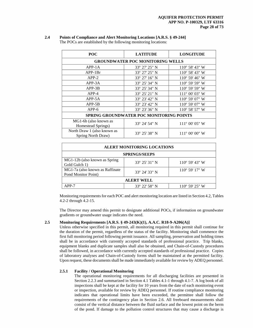
AQUIFER PROTECTION PERMIT APP NO. P-100329, LTF 63316
Page 28 of 73
2.4 Points of Compliance and Alert Monitoring Locations [A.R.S. § 49-244] The POCs are established by the following monitoring locations:
POC LATITUDE LONGITUDE
GROUNDWATER POC MONITORING WELLS APP-1A 33° 27' 25" N 110° 58' 43" W APP-1Br 33° 27' 25" N 110° 58' 43" W
APP-2 33° 27' 16" N 110° 59' 46" W APP-3A 33° 25' 34" N 110° 59' 59" W APP-3B 33° 25' 34" N 110° 59' 59" W APP-4 33° 25' 21" N 111° 00' 03" W
APP-5A 33° 23' 42" N 110° 59' 07" W APP-5B 33° 23' 42" N 110° 59' 07" W APP-6 33° 23' 36" N 110° 58' 57" W
SPRING GROUNDWATER POC MONITORING POINTS MG1-6b (also known as
Homestead Springs) 33° 24' 54" N 111° 00' 05" W
North Draw 1 (also known as Spring North Draw) 33° 25' 38" N 111° 00' 00" W
ALERT MONITORING LOCATIONS
SPRINGS/SEEPS MG1-12b (also known as Spring Gold Gulch 1) 33° 25' 31" N 110° 59' 43" W
MG1-7a (also known as Raffinate Pond Monitor Point) 33° 24' 33" N 110° 59' 17" W
ALERT WELL APP-7 33° 22' 58" N 110° 59' 25" W
Monitoring requirements for each POC and alert monitoring location are listed in Section 4.2, Tables 4.2-2 through 4.2-15. The Director may amend this permit to designate additional POCs, if information on groundwater gradients or groundwater usage indicates the need.
2.5 Monitoring Requirements [A.R.S. § 49-243(K)(1), A.A.C. R18-9-A206(A)] Unless otherwise specified in this permit, all monitoring required in this permit shall continue for the duration of the permit, regardless of the status of the facility. Monitoring shall commence the first full monitoring period following permit issuance. All sampling, preservation and holding times shall be in accordance with currently accepted standards of professional practice. Trip blanks, equipment blanks and duplicate samples shall also be obtained, and Chain-of-Custody procedures shall be followed, in accordance with currently accepted standards of professional practice. Copies of laboratory analyses and Chain-of-Custody forms shall be maintained at the permitted facility. Upon request, these documents shall be made immediately available for review by ADEQ personnel. 2.5.1 Facility / Operational Monitoring
The operational monitoring requirements for all discharging facilities are presented in Section 2.2.3 and summarized in Section 4.1 Tables 4.1-1 through 4.1-7. A log book of all inspections shall be kept at the facility for 10 years from the date of each monitoring event or inspection, available for review by ADEQ personnel. If routine compliance monitoring indicates that operational limits have been exceeded, the permittee shall follow the requirements of the contingency plan in Section 2.6. All freeboard measurements shall consist of the vertical distance between the fluid surface and the lowest point on the berm of the pond. If damage to the pollution control structures that may cause a discharge is

AQUIFER PROTECTION PERMIT APP NO. P-100329, LTF 63316
Page 29 of 73
identified during an inspection, proper repair procedures shall be performed. All repair or modification procedures and material(s) used shall be documented in a logbook or similar. If no damage to the pollution control structures is identified during the quarter, the permittee shall indicate that the required inspections occurred.
2.5.1.1 PLS and Raffinate Processing Facilities
The raffinate used to leach ore is collected as PLS in Gold Gulch No. 1A. The LCRS of the Gold Gulch No. 1A PLS Pond shall be monitored and reported according to the terms and frequencies in Section 4.1, Table 4.1-1.
2.5.1.1.1 Gold Gulch PLS Pond Liner Leakage Monitoring
The Gold Gulch No. 1A PLS Pond LCRS shall be monitored on a weekly basis for liner leakage and pumped as specified in Table 4.1-1 in Section 4.1 of this permit. Records shall be maintained of the volumes pumped and volumes shall be compared to alert levels (ALs) for liner leakage in Table 4.1-1 on a weekly basis to determine response actions. Results shall be submitted to ADEQ in accordance with Table 4.1-1.
2.5.1.2 Tailings Impoundments and Ponds Tailings generated by Pinto Valley's Concentrator shall be monitored and results of monitoring recorded annually in the site logbook according to the terms and frequencies in Section 4.1, Table 4.1-2. Any exceeded values shall be reported in accordance with Section 2.7.3 (Permit Violation and Alert Level Status Reporting). The total average annual deposition volume into both TSF3 and TSF4 shall be monitored and reported according to the terms and frequencies in Section 4.1, Table 4.1-2.
2.5.1.3 Waste Rock Dump Characterization The waste rock shall be characterized, monitored and results reported according to the terms and frequencies in Section 4.1, Table 4.1-3.
2.5.1.4 Facility Operation and BADCT Performance Inspection BADCT associated with each APP-regulated discharging facility, shall be inspected according to the requirements in Table 4.1-4 in Section 4.1. A log book of all inspections shall be kept at the facility for 10 years from the date of each monitoring event or inspection, available for review by ADEQ personnel in accordance with Section 2.7.2. If compliance monitoring indicates that operational limits have been exceeded, the permittee shall follow the requirements of the contingency plan in Section 2.6.
2.5.1.5 Active Monitoring of Pit Containment
Groundwater modeling results have been presented to ADEQ to demonstrate that the pit lake constitutes a sink (PCCZ). Modeling was used as the basis for the BADCT demonstration for containment in the pit. The permittee shall utilize a comprehensive water management plan to ensure that passive containment in the open pit shall be maintained throughout the life of the facility. Modeling and field verification shall be performed as required by this permit to demonstrate that containment is achieved throughout the life, closure and post-closure period of this permit. Pit containment shall be monitored annually through static water level measurements collected from the available and suitable wells listed in Table 4.1-5. These measurements shall be used to confirm pit containment with local groundwater flow toward the open pit and pit water elevation of not more than 3,450 ft amsl except for brief periods of time during emergency situations. The results of the monitoring will be reported to ADEQ as described in Section 2.7.4.3.

AQUIFER PROTECTION PERMIT APP NO. P-100329, LTF 63316
Page 30 of 73
If monitoring indicates that the pit is not contained, the permittee shall follow the requirements of the contingency plan in Section 2.6.2.1 (Exceeding of Alert Levels Set for Operational Conditions).
2.5.1.6 Routine Discharge Monitoring for the Wastewater Treatment Plant
Routine discharge monitoring of the WWTP shall be conducted in accordance with Section 4.3, Table 4.3-1.
2.5.2 Groundwater Monitoring and Sampling Protocols Static water levels shall be measured and recorded prior to sampling. Wells shall be purged of at least three borehole volumes (as calculated using the static water level) or until field parameters (pH, temperature, conductivity) are stable, whichever represents the greater volume. If evacuation results in the well going dry, the well shall be allowed to recover to 80 percent of the original borehole volume, or for 24 hours, whichever is shorter, prior to sampling. If after 24 hours there is not sufficient water for sampling, the well shall be recorded as “dry” for the monitoring event. An explanation for reduced pumping volumes, a record of the volume pumped, and modified sampling procedures shall be reported and submitted with the Self monitoring Report Form (SMRF). Alternatively, the permittee may conduct the sampling using the low-flow purging method as described in the Arizona Water Resources Research Center, March 1995 Field Manual for Water Quality Sampling. The well must be purged until indicator parameters stabilize. Indicator parameters shall include dissolved oxygen, turbidity, pH, temperature, and conductivity. 2.5.2.1 Routine Groundwater Monitoring in POC Wells
Groundwater monitoring of wells listed in Section 4.2, Table 4.2-1 shall be performed on a quarterly basis and a biennial (every 2 years) basis for wells and constituents listed in Section 4.2, Tables 4.2-2 through 4.2-10. SMRFs shall be submitted to ADEQ in accordance with reporting frequencies specified in these tables.
2.5.2.2 Routine Monitoring in POC Springs
Groundwater monitoring shall be performed on a quarterly and biennial in accordance with Section 4.2 Tables 4.2-11 and 4.2-12 to assess groundwater quality in POC springs North Draw 1 and MG1-6b (also known as Homestead Springs). SMRFs shall be submitted to ADEQ in accordance with reporting frequencies specified in these tables.
2.5.2.3 Routine Groundwater Alert Level Monitoring and Seep Monitoring Groundwater monitoring shall be performed on a quarterly and biennial basis in accordance with Section 4.2 Tables 4.2-13 through 4.2-15 to assess groundwater quality in the well APP-7, and in seeps MG1-7a (Raffinate Pond) and MG1-12b (Spring Gold Gulch). SMRFs shall be submitted to ADEQ in accordance with reporting frequencies specified in these tables.
2.5.2.4 Point of Compliance Well Replacement In the event that one or more of the designated POC wells should become unusable or inaccessible due to damage or any other event, a replacement POC well shall be constructed and installed upon approval by ADEQ. If the replacement well is 50 feet or less from the original well, the ALs and aquifer quality limits (AQLs) calculated for the designated POC well shall apply to the replacement well.
2.5.2.5 Aquifer Quality Limits for POC Wells For each of the monitored analytes for which a numeric AWQS has been adopted, the AQL shall be established as follows: 1. If the calculated AL is less than the AWQS, then the AQL shall be set equal
AQUIFER PROTECTION PERMIT APP NO. P-100329, LTF 63316
Page 31 of 73
to the AWQS. 2. If the calculated AL is greater than the AWQS, then the AQL shall be set
equal to the calculated AL value, and no AL shall be set for that constituent at that monitoring point.
ADEQ reserves the right to set ALs and AQLs, where applicable, for those analytes that may have a numeric standard adopted by rule at a future time.
2.5.3 Surface Water Monitoring and Sampling Protocols Surface water monitoring is not required by this permit.
2.5.4 Analytical Methodology
All samples collected for compliance monitoring shall be analyzed using Arizona state-approved methods. If no state-approved method exists, then any appropriate EPA-approved method shall be used. Regardless of the method used, the detection limits must be sufficient to determine compliance with the regulatory limits of the parameters specified in this permit. If all methods have detection limits higher than the applicable limit, the permittee shall follow the contingency requirements of Section 2.6 and may propose “other actions” including amending the permit to set higher limits. Analyses shall be performed by a laboratory licensed by the Arizona Department of Health Services, Office of Laboratory Licensure and Certification unless exempted under A.R.S. § 36-495.02. For results to be considered valid, all analytical work shall meet quality control standards specified in the approved methods. A list of Arizona state-certified laboratories can be obtained at the address below: Arizona Department of Health Services Office of Laboratory Licensure and Certification 250 North 17th Avenue Phoenix, AZ 85007 Phone: (602) 364-0720
2.5.5 Installation and Maintenance of Monitoring Equipment Monitoring equipment required by this permit shall be installed and maintained so that representative samples required by the permit can be collected. If new groundwater wells are determined to be necessary, the construction details shall be submitted to the ADEQ Water Permits Section for approval prior to installation and the permit shall be amended to include any new points.
2.6 Contingency Plan Requirements [A.R.S. § 49-243(K)(3), (K)(7) and A.A.C. R18-9-A204 and R18-9-A205]
2.6.1 General Contingency Plan Requirements
At least one copy of this permit and the approved Contingency & Emergency Response Plan (CERP) shall be maintained at the location where day-to-day decisions regarding the operation of the facility are made. The permittee shall be aware of and follow the CERP. Any AL that is exceeded or any violation of an AQL, DL, or other permit condition shall be reported to ADEQ following the reporting requirements in Section 2.7.3. Some contingency actions involve verification sampling. Verification sampling shall consist of the first follow-up sample collected from a location that previously indicated a violation or the exceedance of an AL or an AQL. Collection and analysis of the verification sample shall use the same protocols and test methods to analyze for the pollutant or pollutants that exceeded an AL or violated an AQL. The permittee is subject to enforcement action for the failure to comply with any contingency actions in this permit. Where verification sampling is specified in this permit, it is the option of the permittee to perform such sampling. If verification sampling is not conducted within the timeframe allotted,
AQUIFER PROTECTION PERMIT APP NO. P-100329, LTF 63316
Page 32 of 73
ADEQ and the permittee shall presume the initial sampling result to be confirmed as if verification sampling has been conducted. The permittee shall be responsible for compliance with contingency plans relating to the exceedance of an AL or violation of a DL, AQL or any other permit condition.
2.6.2 Exceeding of Alert Levels/Performance Levels
2.6.2.1 Exceeding of Performance Levels Set for Operational Conditions 1. Performance Levels Set for Freeboard
In the event that freeboard performance levels in a surface impoundment are not maintained, the permittee shall: a. As soon as practicable, cease or reduce discharging to the impoundment to prevent
overtopping. Remove and properly dispose or recycle to other operations the excess fluid in the reservoir until the water level is restored at or below the permitted freeboard limit.
b. Within 5 days of discovery, evaluate the cause of the incident and adjust operational conditions as necessary to avoid future occurrences.
c. Record in the facility log, the amount of fluid removed, a description of the removal method, and the disposal arrangements. The facility log shall be maintained according to Section 2.7.2.
d. The facility is no longer on alert status once the operational indicator no longer indicates that the freeboard performance level is being exceeded. The permittee shall, however, complete all tasks necessary to return the facility to its pre-alert operating condition.
2. Performance Levels, Other Than Freeboard
a. If exceedance of an operational performance level (PL) listed in Section 4, Table 4.1-4 has been observed or noted during required inspection and operational monitoring, such that the result could cause or contribute to an unauthorized discharge, the permittee shall immediately investigate to determine the cause of the condition. The investigation shall include the following: i. Inspection, testing, and assessment of the current condition of all treatment
or pollutant discharge control systems that may have contributed to the operational performance condition.
ii. Review of recent process logs, reports, and other operational control information to identify any unusual occurrences.
b. The PL exceedance, results of the investigation, and any corrective action taken shall be reported to the Water Quality Compliance Section (WQCS), within 30 days of the discovery of the condition. Upon review of the submitted report, the Department may amend the permit to require additional monitoring, increased frequency of monitoring, or other actions.
c. The permittee shall initiate actions identified in the approved contingency plan referenced in Section 5 and any specific contingency measures identified in Section 2.6 to resolve any problems identified by the investigation which may have led to a PL being exceeded. To implement any other corrective action the permittee shall obtain prior approval from ADEQ according to Section 2.6.6.
2.6.2.3 Exceeding of Alert Levels Set for Action Leakage Rates (ALR)
1. If the operational ALR (action leakage rate) set in Section 4.1, Table 4.1-1, has been exceeded the permittee shall initiate the following actions within 5 days of becoming aware of the exceedance of the action leakage rate at the Gold Gulch 1A PLS Pond LCRS:
a. Pump out all fluid collected in the LCRS into either Gold Gulch No. 1A
PLS Pond or Gold Gulch No. 1 PLS Pond to reduce head on the liner system.
b. Quantify and record the amount of fluid pumped from the LCRS. c. Initiate repair of all identified points of leakage into the LCRS.

AQUIFER PROTECTION PERMIT APP NO. P-100329, LTF 63316
Page 33 of 73
d. Follow reporting requirements in Section 2.7.3 of this permit. Additional response actions based on leakage rates in excess of 2,000 gallons per acre per day, based on the reported wetted acreage, shall at a minimum include all the following, in addition to the requirements in Section 2.7.3:
a. Head reduction on the liner including emptying of the impoundment if
necessary, b. Visual inspections to identify areas of leakage, c. Repair of all identified areas of leakage.
2. The facility is no longer on alert status once the operational indicator no
longer indicates that an AL is being exceeded. The permittee shall, however, complete all tasks necessary to return the facility to its pre-alert operating condition.
3. Upon review of the submitted reports required in Section 2.7.3, the
Department may amend the permit to require additional monitoring, increased frequency of monitoring, amendments to permit conditions or other actions.
2.6.2.4 Exceeding of Alert Levels in Groundwater, Seep and Spring Monitoring
2.6.2.4.1 Alert Levels for Indicator Parameters Not applicable for this permit. 2.6.2.4.2 Alert Levels for Pollutants with Numeric Aquifer Water Quality
Standards 1. If an AL for a pollutant set in Section 4.2, Tables 4.2-2 through 4.2-
15 has been exceeded, the permittee may conduct verification sampling within 5 days of becoming aware of an AL being exceeded. The permittee may use the results of another sample taken between the date of the last sampling event and the date of receiving the result as verification.
2. If verification sampling confirms the AL being exceeded or if the
permittee opts not to perform verification sampling, then the permittee shall increase the frequency of monitoring to monthly. In addition, the permittee shall immediately initiate an investigation of the cause of the AL being exceeded, including inspection of all discharging units and all related pollution control devices, review of any operational and maintenance practices that might have resulted in an unexpected discharge, and hydrologic review of groundwater conditions including upgradient water quality.
3. The permittee shall initiate specific contingency actions identified
in Section 2.6 to resolve any problems identified by the investigation which may have led to an AL being exceeded. To implement any other corrective action the permittee shall obtain prior approval from ADEQ according to Section 2.6.6. Alternatively, the permittee may submit a technical demonstration, subject to written approval by the Water Permits Section, that although an AL is exceeded, pollutants are not reasonably expected to cause a violation of an AQL. The demonstration may propose a revised AL or monitoring frequency for approval in writing by the Water Permits Section.
4. Within 30 days after confirmation of an AL being exceeded, the
permittee shall submit the laboratory results to the Water Quality

AQUIFER PROTECTION PERMIT APP NO. P-100329, LTF 63316
Page 34 of 73
Compliance Section, Data Unit along with a summary of the findings of the investigation, the cause of the AL being exceeded, and actions taken to resolve the problem.
5. Upon review of the submitted report, the Department may amend
the permit to require additional monitoring, increased frequency of monitoring, or other actions.
6. The increased monitoring required as a result of ALs being exceeded
may be reduced back to the pre-alert frequency if the results of three sequential sampling events demonstrate that no parameters exceed the AL.
2.6.2.4.3 Alert Levels to Protect Downgradient Users from Pollutants without
Numeric Aquifer Water Quality Standards Not applicable for this permit.
2.6.2.5 Exceeded Alert Levels for Waste Rock Characterization
Waste rock will be tested for acid-generating potential, according to Table 4.1-3. Potentially acid-generating waste rock deposited in tailings as indicated by exceedances of the criterion for action in Table 4.1-3 shall be enclosed in non acid-generating waste rock overlying fine-grained tailings. Any action other than isolating the acid-generating waste rock requires prior notification and approval by ADEQ. Any toe slips and crest failures at waste rock dumps or damage to the stability or integrity of stormwater controls associated with waste rock dumps identified during regular inspections required in Table 4.1-6 shall be immediately repaired.
2.6.3 Discharge Limitations Violations
2.6.3.1 Liner Failure, Containment Structure Failure, or Unexpected Loss of Fluid
In the event of liner failure, containment structure failure, or unexpected loss of fluid as described in Section 2.3, the permittee shall take the following actions: 1. As soon as practicable, cease all discharges to the surface impoundment as
necessary to prevent any further releases to the environment. 2. Within 24 hours of discovery, notify ADEQ WQCS. 3. Within 5 days of discovery of a failure that resulted in a release to the
subsurface, collect representative samples of the fluid remaining in the surface impoundment. Samples shall be analyzed for the parameters specified in Section 4, Table 4.2.3. Within 30 days of the incident, submit a copy of the analytical results to ADEQ WQCS.
4. Within 15 days of discovery, initiate an evaluation to determine the cause for the incident. Identify the circumstances that resulted in the failure and assess the condition of the surface impoundment and liner system. Implement corrective actions as necessary to resolve the problems identified in the evaluation. Initiate repairs to any failed liner, system, structure, or other component as needed to restore proper functioning of the surface impoundment. The permittee shall not resume discharging to the surface impoundment until repairs of any failed liner or structure are performed. Repair procedures, methods, and materials used to restore the system(s) to proper operating condition shall be described in the facility log/recordkeeping file and available for ADEQ review.
5. As soon as practicable, remove fluid remaining in the surface impoundment as necessary to prevent further releases to the subsurface and/or to perform repairs. Record in the facility log/recordkeeping file the amount of fluid removed, a description of the removal method, and other disposal arrangements. The facility log/recordkeeping file shall be maintained according to Section 2.7.2.
AQUIFER PROTECTION PERMIT APP NO. P-100329, LTF 63316
Page 35 of 73
6. Within 30 days of discovery of the incident, submit a report to ADEQ as specified in Section 2.7.3. Include a description of the actions performed in Subsections 1 through 5 listed above. Upon review of the report, ADEQ may request additional monitoring or remedial actions.
7. Within 60 days of discovery, conduct an assessment of the impacts to the subsoil and/or groundwater resulting from the incident. If soil or groundwater is impacted such that it could cause or contribute to an exceedance of an AQL at the applicable point of compliance, submit to ADEQ, for approval, a corrective action plan to address such impacts, including identification of remedial actions and/or monitoring, and a schedule for completion of activities. At the direction of ADEQ, the permittee shall implement the approved plan.
8. Within 30 days of completion of corrective actions, submit to ADEQ, a written report as specified in section 2.6.6. Upon review of the report, ADEQ may amend the permit to require additional monitoring, increased frequency of monitoring, amendments to permit conditions, or other actions.
2.6.3.2 Overtopping of a Surface Impoundment
If overtopping of fluid from a permitted surface impoundment occurs, and results in a discharge pursuant to A.R.S. § 49-201(12), the permittee shall: 1. As soon as practicable, cease all discharges to the surface impoundment to
prevent any further releases to the environment. 2. Within 24 hours of discovery, notify ADEQ WQCS. 3. Within 5 days, collect representative samples of the fluid contained in the
surface impoundment. Samples shall be analyzed for the parameters specified in Section 4.1, Table 4.4-1. Within 30 days of the incident, submit a copy of the analytical results to ADEQ WQCS.
4. As soon as practicable, remove and properly dispose of excess water in the impoundment until the water level is restored at or below the appropriate freeboard as described in Section 4.1, Table 4.1-4. Record in the facility log, the amount of fluid removed, a description of the removal method, and the disposal arrangements. The facility log/recordkeeping file shall be maintained according to Section 2.7.2.
5. Within 30 days of discovery, evaluate the cause of the overtopping and identify the circumstances that resulted in the incident. Implement corrective actions and adjust operational conditions as necessary to resolve the problems identified in the evaluation. Repair any systems as necessary to prevent future occurrences of overtopping.
6. Within 30 days of discovery of overtopping, submit a report to ADEQ as specified in section 2.7.3. Include a description of the actions performed in Items 1 through 5 listed above. Upon review of the report, ADEQ may request additional monitoring or remedial actions.
7. Within 60 days of discovery, and based on sampling in Item 3 above, conduct an assessment of the impacts to the subsoil and/or groundwater resulting from the incident.
8. If soil or groundwater is impacted such that it could cause or contribute to an exceedance of an AQL at the applicable point of compliance, submit to ADEQ for approval, a corrective action plan to address such impacts, including identification of remedial actions and/or monitoring, and a schedule for completion of activities. At the direction of ADEQ, the permittee shall implement the approved plan.
9. Within 30 days of completion of corrective actions, submit to ADEQ, a written report as specified in Section 2.6.6. Upon review of the report, ADEQ may amend the permit to require additional monitoring, increased frequency of monitoring, amendments to permit conditions, or other actions.
2.6.3.3 Inflows of Unexpected Materials to a Surface Impoundment
The types of materials that are expected to be placed in the permitted surface

AQUIFER PROTECTION PERMIT APP NO. P-100329, LTF 63316
Page 36 of 73
impoundments are specified in Section 2.2. If any unexpected materials flow to a permitted surface impoundment, the permittee shall: 1. As soon as practicable, cease all unexpected inflows to the surface
impoundment(s). 2. Within 24 hours of discovery, notify ADEQ WQCS. 3. Within 5 days of the incident, identify the source of the material and
determine the cause for the inflow. Characterize the unexpected material and contents of the affected impoundment, and evaluate the volume and concentration of the material to determine if it is compatible with the surface impoundment liner. Based on the evaluation of the incident, repair any systems or equipment and/or adjust operations, as necessary to prevent future occurrences of inflows of unexpected materials.
4. Within 30 days of an inflow of unexpected materials, submit a report to ADEQ as specified in section 2.7.3. Include a description of the actions performed in Items 1 through 3 listed above. Upon review of the report, ADEQ may request additional monitoring or remedial actions.
5. Upon review of the report, ADEQ may amend the permit to require additional monitoring, increased frequency of monitoring, amendments to permit conditions, or other actions.
2.6.3.1 Waste Rock Dump Failures
Mitigating actions for the waste rock dumps shall be initiated if there is evidence of any of the following conditions: measurable slips at the toe of a waste rock dump, evidence of a crest failure, evidence of breaching of stormwater run on/runoff control features and berms protecting closed facilities, ponding on closed facilities, evidence of visible erosion or other damage that may impact berm integrity or stability. Mitigating actions shall include repairing the affected facility, removing discharged material that has the potential to affect the aquifer, and other actions necessary to meet permit requirements.
2.6.3.2 Slope and Berm Failures If a slope or berm failure involving the leach dumps, liners, surface impoundments or retention structures (dams) occurs which affects the ability of the facility to operate safely or results in an unauthorized discharge, the permittee shall promptly close the active area in the vicinity of the failure, and conduct a field investigation of the failure to analyze its origin and extent, its impact on the facility operations, temporary and permanent repairs and changes in operational plans considered necessary. Within 30 days of a slope or berm failure, the permittee shall submit a written report which includes the documentation specified in Section 2.7.3 of this permit. The permittee shall initiate the actions necessary to mitigate the impacts of the failure, consistent with Department approval.
2.6.3.3 Maximum Deposition Limit Violation
The permittee shall notify the Department in accordance with Section 2.7.3, should a MDL as specified in Table 4.1-2, Section 4.1 be violated. The permittee shall submit a written report which includes the documentation specified in Section 2.7.3 of this permit if the MDL is exceeded.
2.6.4 Aquifer Quality Limit Violation
1. If an AQL set in Section 4.2, for a POC Well has been exceeded, the permittee may conduct verification sampling within 5 days of becoming aware of an AQL being exceeded. The permittee may use the results of another sample taken between the date of the last sampling event and the date of receiving the result as verification. If verification sampling does not verify the exceedance, the initial exceedance shall be
AQUIFER PROTECTION PERMIT APP NO. P-100329, LTF 63316
Page 37 of 73
reported in the Annual Monitoring and Compliance Report and no further action is required by the permittee for that event.
2. If verification sampling confirms that the AQL is violated for any parameter or if the
permittee opts not to perform verification sampling, then within 30 days the permittee shall increase the frequency of monitoring to monthly in the subject well or spring with the exceeded value for the quarterly monitoring constituents in Section 4.2.
In addition, the permittee shall immediately initiate an evaluation for the cause of the
violation, including inspection of all discharging units and all related pollution control devices, and review of any operational and maintenance practices that might have resulted in unexpected discharge.
The permittee also shall submit a report according to Section 2.7.3, which includes a
summary of the findings of the investigation, the cause of the violation, and actions taken to resolve the problem. A verified exceedance of an AQL will be considered a violation unless the permittee demonstrates within 30 days that the exceedance was not caused or contributed to by pollutants discharged from the facility. Unless the permittee has demonstrated that the exceedance was not caused or contributed to by pollutants discharged from the facility, the permittee shall consider and ADEQ may require corrective action that may include control of the source of discharge, cleanup of affected soil, surface water or groundwater, and mitigation of the impact of pollutants on existing uses of the aquifer. Corrective actions shall either be specifically identified in this permit, included in an ADEQ approved contingency plan, or separately approved according to Section 2.6.6.
3. Upon review of the submitted report, the Department may amend the permit to require
additional monitoring, increased frequency of monitoring, or other actions. 4. If the exceedance continues for 120 days, the permittee shall notify any downstream
or down gradient users who may be directly affected by the discharge. 5. The permittee shall continue monitoring at the increased frequency until the
contaminant(s) are below the AQL and AL for three consecutive months.
2.6.5 Emergency Response and Contingency Requirements for Unauthorized Discharges [A.R.S. § 49-201(12) and A.R.S. § 49-241] 2.6.5.1 Duty to Respond
The permittee shall act immediately to correct any condition resulting from a discharge pursuant to A.R.S. § 49-201(12) if that condition could pose an imminent and substantial endangerment to public health or the environment.
2.6.5.2 Discharge of Hazardous Substances or Toxic Pollutants
In the event of any unauthorized discharge pursuant to A.R.S. § 49-201(12) of suspected hazardous substances (A.R.S. § 49-201(19)) or toxic pollutants (A.R.S. § 49-243(I)) on the facility site, the permittee shall promptly isolate the area and attempt to identify the discharged material. The permittee shall record information, including name, nature of exposure and follow-up medical treatment, if necessary, on persons who may have been exposed during the incident. The permittee shall notify the ADEQ Water Quality Compliance Section within 24 hours upon discovering the discharge of hazardous material which (a) has the potential to cause an AWQS or AQL to be exceeded, or (b) could pose an endangerment to public health or the environment.
2.6.5.3 Discharge of Non-hazardous Materials
In the event of any unauthorized discharge pursuant to A.R.S. § 49-201(12) of
AQUIFER PROTECTION PERMIT APP NO. P-100329, LTF 63316
Page 38 of 73
non-hazardous materials from the facility, the permittee shall promptly attempt to cease the discharge and isolate the discharged material. Discharged material shall be removed and the site cleaned up as soon as possible. The permittee shall notify the ADEQ Water Quality Compliance Section within 24 hours upon discovering the discharge of non-hazardous material which (a) has the potential to cause an AQL to be exceeded, or (b) could pose an endangerment to public health or the environment.
2.6.5.4 Reporting Requirements
The permittee shall submit a written report for any unauthorized discharges reported under Sections 2.6.5.2 and 2.6.5.3 to ADEQ Water Quality Compliance Section within 30 days of the discharge or as required by subsequent ADEQ action. The report shall summarize the event, including any human exposure, and facility response activities and include all information specified in Section 2.7.3. If a notice is issued by ADEQ subsequent to the discharge notification, any additional information requested in the notice shall also be submitted within the time frame specified in that notice. Upon review of the submitted report, ADEQ may require additional monitoring or corrective actions.
2.6.6 Corrective Actions
Specific contingency measures identified in Section 2.6 have already been approved by ADEQ and do not require written approval to implement. With the exception of emergency response actions taken under Section 2.6.5, the permittee shall obtain written approval from the Water Permits Section prior to implementing a corrective action to accomplish any of the following goals in response to exceeding an AL or violation of an AQL, DL, or other permit condition: 1. Control of the source of an unauthorized discharge; 2. Soil cleanup; 3. Cleanup of affected surface waters; 4. Cleanup of affected parts of the aquifer; and/or 5. Mitigation to limit the impact of pollutants on existing uses of the aquifer. Within 30 days of completion of any corrective action, the operator shall submit to the ADEQ Water Quality Compliance Section, a written report describing the causes, impacts, and actions taken to resolve the problem.
2.7 Reporting and Recordkeeping Requirements [A.R.S. §49-243(K)(2) and A.A.C. R18-9-A206(B) and R18-9-A207] 2.7.1 Self-monitoring Report Forms
1. When submitting hard copy, the permittee shall complete the Self-monitoring Report Form (SMRF) provided by ADEQ including contact information for the person completing the form. Submit the completed form to the Water Quality Compliance Data and Enforcement Unit.
2. The permittee shall complete the SMRF to the extent that the information reported may be entered on the form. If no information is required during a reporting period, the permittee shall enter “not required” on the form and include an explanation, and submit form to the Water Quality Compliance Data and Enforcement Unit. The permittee shall use the format devised by ADEQ.
3. The tables contained in Section 4.2 list the parameters to be monitored and the frequency for reporting results for groundwater compliance monitoring.
4. In addition to the SMRF, the information contained in A.A.C. R18-9-A206(B)(1) shall be included for exceeding an AL or violation of an AQL, DL, or any other permit condition being reported in the current reporting period.
AQUIFER PROTECTION PERMIT APP NO. P-100329, LTF 63316
Page 39 of 73
2.7.2 Operation Inspection / Log Book Recordkeeping A signed copy of this permit shall be maintained at all times at the location where day-to-day decisions regarding the operation of the facility are made. A log book (paper copies, forms or electronic data) of the inspections and measurements required by this permit shall be maintained at the location where day-to-day decisions are made regarding the operation of the facility. The log book shall be retained for ten years from the date of each inspection, and upon request, the permit and the log book shall be made immediately available for review by ADEQ personnel. The information in the log book shall include, but not be limited to, the following information as applicable: 1. Name of inspector; 2. Date and shift inspection was conducted; 3. Condition of applicable facility components; 4. Any damage or malfunction, and the date and time any repairs were performed; 5. Documentation of sampling date and time; 6. Any other information required by this permit to be entered in the log book, and 7. Monitoring records for each measurement shall comply with R18-9-A206(B)(2). 8. Results of routine inspections performed in accordance with Section 4.1, Table 4.1-4.
2.7.3 Permit Violation and Alert Level Status Reporting 1. The permittee shall notify the Water Quality Compliance Section, Enforcement Unit
in writing within 5 days (except as provided in Section 2.6.5) of becoming aware of a violation of any permit condition, DL, or of an AL being exceeded.
2. The permittee shall submit a written report to the Water Quality Compliance Section,
Enforcement Unit within 30 days of becoming aware of the violation of any permit condition or DL. The report shall document all of the following: a. Identification and description of the permit condition for which there has been a
violation and a description of its cause. b. The period of violation including exact date(s) and time(s), if known, and the
anticipated time period during which the violation is expected to continue. c. Any corrective action taken or planned to mitigate the effects of the violation, or
to eliminate or prevent a recurrence of the violation. d. Any monitoring activity or other information which indicates that any pollutants
would be reasonably expected to cause a violation of an Aquifer Water Quality Standard.
e. Proposed changes to the monitoring which include changes in constituents or increased frequency of monitoring.
f. Description of any malfunction or failure of pollution control devices or other equipment or processes.
2.7.4 Operational, Other or Miscellaneous Reporting
The permittee shall report operational conditions listed in Section 4.1, Table 4.1-4 in a log book according to Section 2.7.6. If none of the conditions occur, the report shall say “no event" for a particular reporting period. If the facility is not in operation, the permittee shall indicate that fact in the log book. The permittee shall submit data required in Section 4.1 and 4.2 tables regardless of the operating status of the facility unless otherwise approved by the ADEQ or allowed in this permit. 2.7.4.1 Groundwater Assessment 5-Year Reports
The permittee shall submit a Groundwater Assessment Report every 5 years under the Compliance Schedule in Section 3.0 of this permit. The purpose of this assessment shall be to verify the adequacy of the POC monitoring well locations, assess hydraulic capture in the pit, evaluate the adequacy of the groundwater monitoring program, evaluate BADCT performance as observed in groundwater monitoring, and to assess the status of the water elevation in the pit.
AQUIFER PROTECTION PERMIT APP NO. P-100329, LTF 63316
Page 40 of 73
2.7.4.2 Annual Reporting As required by this permit, the permittee shall submit Annual Reports for various forms of monitoring performed under this permit. Each year the permittee shall submit an Annual Report to the Water Quality Compliance Section and the Water Permits Section summarizing the results of the Facility’s performance monitoring for the calendar year in accordance with the table in Section 2.7.6. Results of piezometer monitoring at the Tailings Impoundments shall be summarized in the Annual Report. Reports for waste rock characterization/monitoring shall be included in this report along with an assessment of whether waste rock monitoring results suggest that waste rock is acid generating and assessing the potential impact to groundwater quality with respect to compliance with AWQS at designated POCs for waste rock disposal areas. The report shall be divided into Groundwater, Discharge and BADCT Monitoring and Compliance Status (a summary of all permit exceedances and violations if any and response actions taken). The report shall also include identification and discussion of any laboratory results that fell outside of the laboratory QA/QC criteria and AQLs and ALs required by this permit. Response actions for BADCT performance monitoring shall be summarized in this report for any exceeded performance monitoring as described in (2) below. Appropriate components of the report required by this Section shall be sealed by an Arizona-registered professional geologist or registered professional engineer, in accordance with Arizona Board of Technical Registration (BTR) requirements. 1. Groundwater Monitoring. This section of the Annual Monitoring and
Compliance Report shall contain the following information: a. Quarterly groundwater monitoring summary tables of results for each
POC well and Alert Well in separate tables; b. All exceedances verified during the one year reporting period; and, c. Annual groundwater contour map for each aquifer at the facility
intersected by POC wells, developed using modeling software or if hand developed, accompanied by calculations.
2. Results of BADCT Monitoring required by Table 4.1-4 shall be summarized
in the annual report along with response actions taken under Section 2.7.3. BADCT monitoring shall follow the inspection and monitoring schedule in Table 4.1-4.
3. Results of Active Monitoring for Pit Containment required by Table 4.1-5 shall be summarized in the annual report along with response actions taken under Section 2.7.3. The summary shall include a potentiometric surface map and longitudinal and transverse cross-sections of the open pit.
2.7.4.3 Well Installation Reports
A well installation report shall be submitted to ADEQ within 90 days of the completion of any new well installations in accordance with Section 2.4 of this permit and the Compliance Schedule in Section 3.0. Well installation reports shall be sealed in accordance with Arizona BTR requirements and shall include the following:
1. Arizona Department of Water Resources (ADWR) Notice of Intent (NOI)
and Well Drilling Report; 2. Boring log and well as-built diagram;

AQUIFER PROTECTION PERMIT APP NO. P-100329, LTF 63316
Page 41 of 73
3. Total depth of well measured after installation; 4. Top of well casing or sounding tube (whichever is used as the fixed reference
measuring point) and ground surface elevation; 5. Geophysical logging reports and subsurface sampling results; 6. Description of well drilling method; 7. Description of well development method; 8. Summary of analytical results for initial groundwater sample collected after
installation; and 9. GPS coordinates for each new well.
2.7.4.4 Well Abandonment Reports
If monitor wells associated with this permit are abandoned due to poor performance, casing collapse, or other reasons, or are abandoned at the end of the post-closure period, then within 90 days of completing abandonment, the permittee shall submit a well abandonment report to ADEQ Water Permits Section. Appropriate contents of the report shall be sealed by an Arizona professional geologist or professional engineer, in accordance with BTR requirements. Well abandonment records shall be provided to ADEQ within 90 days of monitor well abandonment and shall include: 1. Copies of ADWR NOI to Abandon; 2. Copies of ADWR Abandonment Reports; 3. A description of the methods used to seal the well casing and the perforated
or screened interval of the well; and 4. GPS coordinates of the former well location.
2.7.5 Reporting Location
All SMRFs shall be submitted to: Arizona Department of Environmental Quality Water Quality Compliance Data and Enforcement Unit Mail Code: 5415B-1 1110 W. Washington Street Phoenix, AZ 85007 Phone (602) 771-4681
All documents required by this permit to be submitted to the Water Quality Compliance Section shall be directed to:
Arizona Department of Environmental Quality Water Quality Compliance Section Mail Code: 5415B-1 1110 W. Washington Street Phoenix, AZ 85007 Phone (602) 771-4497
All documents required by this permit to be submitted to the Water Permits Section shall be directed to:
Arizona Department of Environmental Quality Water Permits Section Mail Code: 5415B-3 1110 W. Washington Street Phoenix, AZ 85007 Phone (602) 771-4428
2.7.6 Reporting Deadline
The following table lists the quarterly report due dates1:
1 A post-mark date no later than the due date is considered meeting the due date requirements under this Section.

AQUIFER PROTECTION PERMIT APP NO. P-100329, LTF 63316
Page 42 of 73
Monitoring conducted during quarter: Quarterly Report due by: January-March April 30
April-June July 30 July-September October 30
October-December January 30 The following table lists the additional report due dates2:
Report: Report due by: Annual (previous Calendar Year) March 30
Biennial SMRFs (Previous 2-year Period) March 30
2.7.7 Changes to Facility Information in Section 1.0 The Water Permits Section and Water Quality Compliance Section shall be notified within 10 days of any change of facility information including Facility Name, Permittee Name, Mailing or Street Address, Facility Contact Person or Emergency Telephone Number.
2.8 Temporary Cessation [A.R.S. § 49-243(K)(8) and A.A.C. R18-9-A209(A)] The permittee shall give written notice to the Water Quality Compliance Section before ceasing operation of the facility for a period of 60 days or greater. The permittee shall take the following measures upon temporary cessation: At the time of notification the permittee shall submit for ADEQ approval a plan for maintenance of discharge control systems and for monitoring during the period of temporary cessation. Immediately following ADEQ’s approval, the permittee shall implement the approved plan. If necessary, ADEQ shall amend permit conditions to incorporate conditions to address temporary cessation. During the period of temporary cessation, the permittee shall provide written notice to the Water Quality Compliance Section of the operational status of the facility every 3 years. If the permittee intends to permanently cease operation of any facility, the permittee shall submit closure notification, as set forth in Section 2.9 below.
2.9 Closure [A.R.S. §§ 49-243(K)(6), 49-252 and A.A.C. R18-9-A209(B)] For a facility addressed under this permit, the permittee shall give written notice of closure to the Water Quality Compliance Section of the permittee’s intent to cease operation without resuming activity for which the facility was designed or operated.
2.9.1 Closure Plan
Within 90 days following notification of closure, the permittee shall submit for approval to the Water Permits Section, a Closure Plan which meets the requirements of A.R.S. § 49-252 and A.A.C. R18-9-A209(B)(3). Closure of the various facilities at the Pinto Valley Mine shall use one of the following general closure methods, depending on the particular facility: 1. Contouring slopes to appropriate angles. 2. Reservoir, pond, and ditch closures. 3. Overall drainage control. These methods are detailed in the Pinto Valley Operations Closure and Post-Closure Strategy dated August 13, 2013, as amended. If the closure plan achieves clean closure immediately, ADEQ shall issue a letter of approval to the permittee. If the closure plan contains a schedule for bringing the facility to a clean closure configuration at a future date, ADEQ may incorporate any part of the schedule as an amendment to this permit.
2.9.2 Closure Completion
2 A post-mark date no later than the due date is considered meeting the due date requirements under this Section.

AQUIFER PROTECTION PERMIT APP NO. P-100329, LTF 63316
Page 43 of 73
Upon completion of closure activities, the permittee shall give written notice to the Water Permits Section indicating that the approved Closure Plan has been implemented fully and providing supporting documentation to demonstrate that clean closure has been achieved (soil sample results, verification sampling results, groundwater data, as applicable). If clean closure has been achieved, ADEQ shall issue a letter of approval to the permittee at that time. If any of the following conditions apply, the permittee shall follow the terms of post-closure stated in this permit: 1. Clean closure cannot be achieved at the time of closure notification or within 1 year
thereafter under a diligent schedule of closure actions; 2. Further action is necessary to keep the facility in compliance with AWQS at the
applicable POC; 3. Continued action is required to verify that the closure design has eliminated discharge
to the extent intended; 4. Remediation or mitigation measures are necessary to achieve compliance with Title
49, Ch. 2; and/or 5. Further action is necessary to meet property use restrictions.
2.10 Post-closure [A.R.S. §§ 49-243(K)(6), 49-252 and A.A.C. R18-9-A209(C)] Post-closure requirements shall be established based on a review of facility closure actions and will be subject to review and approval by the Water Permits Section. In the event clean closure cannot be achieved pursuant to A.R.S. § 49-252, the permittee shall submit for approval to the Water Permits Section a Post-closure Plan that addresses post-closure maintenance and monitoring actions at the facility. The Post-closure Plan shall meet all requirements of A.R.S. §§ 49-201(30) and 49-252 and A.A.C. R18-9-A209(C). Upon approval of the Post-closure Plan, this permit shall be amended or a new permit shall be issued to incorporate all post-closure controls and monitoring activities of the Post-closure Plan. 2.10.1 Post-closure Plan
The Post-closure Plan will be developed at the time of closure, if required. 2.10.2 Post-closure Completion
The permittee shall indicate ADEQ notification process and post-closure completion requirements in the Post-closure Plan, if required.

AQUIFER PROTECTION PERMIT APP NO. P-100329, LTF 63316
Page 44 of 73
3.0 COMPLIANCE SCHEDULE [A.R.S. § 49-243(K)(5) AND A.A.C. R18-9-A208] For each compliance schedule item listed below, the permittee shall submit the required information, including a cover letter that lists the compliance schedule items, to the Water Permits Section. A copy of the cover letter must also be submitted to the Water Quality Compliance Section.
No. Description Due By: Permit
Amendment Required?
Groundwater Assessment
1
Groundwater Assessment Reports: Every 5 years, perform a groundwater assessment regarding data gaps and adequacy of well locations and/or screened intervals and the passive containment in the Pit. Update groundwater model in accordance with Section 2.7.4 of this permit.
Every 5 Years, last completed in 2012
No
2
First Annual Report on Pit Containment and Assessment of the Adequacy of the Pit Containment Active Monitoring Well Network. As part of the first annual report on Pit Containment assess the adequacy of the network of monitoring wells in Table 4.1-5. If the network is inadequate to demonstrate pit containment, the permittee will propose additional wells specifying well locations, depths and screened intervals and a schedule for well installation. This compliance schedule item may require an “other” permit amendment adding wells to Table 4.1-5.
Completed: 3/20/08, and annually thereafter
No
Annual and Biennial reports
3
Annual Reporting: Submit an Annual Report. Submit SMRFs as required for specific monitoring and Section 2.7.1 and provide a summary of results in the next Annual Report. Submit Annual Report in accordance with Section 2.7.4of this permit.
Every Year No
4
Biennial Reporting: Submit SMRFs as required for specific monitoring and provide a summary of results in the next Annual Report, as per Table 4.2.1 through 4.2.15.
Every 2 Years (even numbered years)
.No
Road Crossing Pond
5
Provide BADCT design and closure costs for the non-stormwater pond: Submit acceptable design details per BADCT Section 2.2 for the Road Crossing Pond, a non-stormwater pond. Also, submit acceptable closure and post-closure costs for this facility.
No later than 5/28/16 Yes
Financial Assurance Mechanism
6
The permittee shall submit updated cost estimates for facility closure and post-closure, as per A.A.C. R18-9-A201(B)(5) and A.R.S. 49-243.N.2.a, and an updated financial assurance demonstration for the updated cost estimate as per A.A.C. R18-9-A203.
Every 6 years from the date of permit signature, for the duration of the permit.
Yes
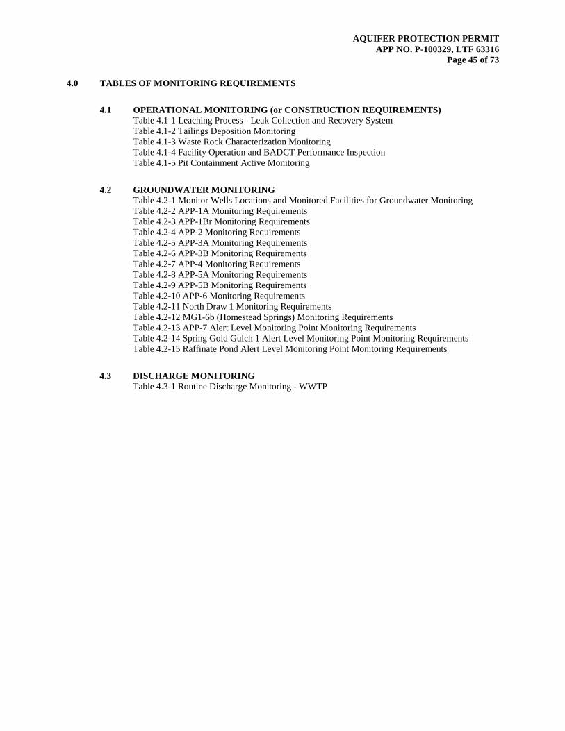
AQUIFER PROTECTION PERMIT APP NO. P-100329, LTF 63316
Page 45 of 73
4.0 TABLES OF MONITORING REQUIREMENTS
4.1 OPERATIONAL MONITORING (or CONSTRUCTION REQUIREMENTS) Table 4.1-1 Leaching Process - Leak Collection and Recovery System Table 4.1-2 Tailings Deposition Monitoring Table 4.1-3 Waste Rock Characterization Monitoring Table 4.1-4 Facility Operation and BADCT Performance Inspection Table 4.1-5 Pit Containment Active Monitoring
4.2 GROUNDWATER MONITORING Table 4.2-1 Monitor Wells Locations and Monitored Facilities for Groundwater Monitoring Table 4.2-2 APP-1A Monitoring Requirements Table 4.2-3 APP-1Br Monitoring Requirements Table 4.2-4 APP-2 Monitoring Requirements Table 4.2-5 APP-3A Monitoring Requirements Table 4.2-6 APP-3B Monitoring Requirements Table 4.2-7 APP-4 Monitoring Requirements Table 4.2-8 APP-5A Monitoring Requirements Table 4.2-9 APP-5B Monitoring Requirements Table 4.2-10 APP-6 Monitoring Requirements Table 4.2-11 North Draw 1 Monitoring Requirements Table 4.2-12 MG1-6b (Homestead Springs) Monitoring Requirements Table 4.2-13 APP-7 Alert Level Monitoring Point Monitoring Requirements Table 4.2-14 Spring Gold Gulch 1 Alert Level Monitoring Point Monitoring Requirements Table 4.2-15 Raffinate Pond Alert Level Monitoring Point Monitoring Requirements
4.3 DISCHARGE MONITORING Table 4.3-1 Routine Discharge Monitoring - WWTP

AQUIFER PROTECTION PERMIT APP NO. P-100329, LTF 63316
Page 46 of 73
4.1 Operational Monitoring
Table 4.1-1 Leaching Process – Leak Collection and Recovery System
Sampling Point Number Identification Latitude Longitude
002 Gold Gulch No. 1A Leak Detection Sump 33o 25' 04" N 110o 59' 03" W
Parameter / Unit Liner Leakage Alert Level Monitoring Frequency Reporting Frequency
Fluid Presence / gal/day N/A3 Weekly Quarterly4
Volume Pumped / gal/day N/A Weekly Quarterly Rate Pumped / gal/day N/A Weekly Quarterly Pond Elevation / feet N/A Weekly Quarterly Action Leakage Rate (ALR) / gal/day Maximum ALR5: 8,130 Weekly Quarterly pH / Standard Units (SU) N/A Weekly Quarterly Specific Conductance / µmho/cm N/A Weekly Quarterly
Table 4.1-2 Tailings Deposition Monitoring (TSF3 and TSF4
Maximum Deposition Limit (MDL) Monitoring Frequency Reporting Frequency 32,000,000 tons annually Annually Annual in site logbook
3 N/A = not applicable 4 SMRFs shall be submitted on a Quarterly Basis in accordance with Section 2.7 of this permit. Exceeded values shall be reported
in accordance with Section 2.7.3. 5 Based on a maximum dry weather pond acreage of 6.5 acres and pond level elevation of 3495.5 feet amsl. If leakage totals from
Sump 002 is less than this amount, no action is necessary.

AQUIFER PROTECTION PERMIT APP NO. P-100329, LTF 63316
Page 47 of 73
Table 4.1-3 Waste Rock Characterization Monitoring
Sampling Point Number Identification Latitude Longitude
008 Northside Dump 9.1 33o 25' 35" N 110o 58' 47" W 009 Northside Dump 9.11 33o 25' 23" N 110o 58' 49" W 010 Northside Dump 9.12 33o 25' 13" N 110o 58' 44" W 011 Northside Dump 9.3 33o 24' 25" N 110o 58' 43" W
013 Southside Dump 13 33o 24' 03" N 110o 58' 18" W 015 19 Dump 33o 23' 36" N 110o 57' 24" W 016 19.1 Dump 33o 23' 49" N 110o 57' 51" W 017 19 Extension Dump 33o 23' 20" N 110o 57' 25" W 018 North Barn Marginal Dump 33° 24' 17" N 110° 58' 37" W 019 Castle Dome Marginal Dump 33° 24' 28" N 110° 57' 33" W
022 Main Dump 33°25’22.64”N 110°58’00.65”W
Parameter Monitoring Frequency
Reporting Frequency Criteria for Action
Acid Base Accounting (ABA) by Modified Sobek Method
Every 10 million tons per active
dump
Annually If large volume of waste rock has significant AP; NNP < -20 kilograms (kg) equivalent CaCO3/ton or if NP/AP <1
Synthetic Precipitation Leaching Procedure (SPLP) by EAP 1312
Every 10 million tons per active
dump
Annually SPLP results will be used to assess the potential for metal leaching and develop closure remediation plans.
If ABA results indicate acid-generating potential, then that section of the waste rock dump shall be covered at closure on the top and sides with non-acid generating waste rock. SPLP results will be used in assessing the potential impact of waste rock on aquifer water quality at closure and in developing closure remediation plans.
Notes: Arizona Mining BADCT Guidance Manual, Arizona Department of Environmental Quality, 2005, Appendix B, p. B-8 NP = Acid-neutralizing Potential AP = Acid-generating Potential NNP = Net Neutralizing Potential = NP-AP, as kg CaCO3/ton of sample
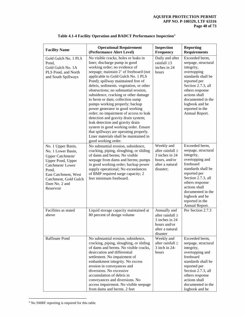
AQUIFER PROTECTION PERMIT APP NO. P-100329, LTF 63316
Page 48 of 73
Table 4.1-4 Facility Operation and BADCT Performance Inspection6
Facility Name Operational Requirement (Performance Alert Level)
Inspection Frequency
Reporting Requirements
Gold Gulch No. 1 PLS Pond, Gold Gulch No. 1A PLS Pond, and North and South Spillways
No visible cracks, holes or leaks in liner; discharge pump in good working order; no evidence of seepage; maintain 2’ of freeboard (not applicable to Gold Gulch No. 1 PLS Pond); spillway maintained free of debris, sediments. vegetation, or other obstructions; no substantial erosion, subsidence, cracking or other damage to berm or dam; collection sump pumps working properly; backup power generator in good working order; no impairment of access to leak detection and gravity drain system; leak detection and gravity drain system in good working order. Ensure that spillways are operating properly. Liner materials shall be maintained in good working order.
Daily and after rainfall ≥3 inches in 24 hours
Exceeded berm, seepage, structural integrity, overtopping standards shall be reported per Section 2.7.3, all others response actions shall documented in the logbook and be reported in the Annual Report.
No. 1 Upper Basin, No. 1 Lower Basin, Upper Catchment/ Upper Pond, Upper Catchment/ Lower Pond, East Catchment, West Catchment, Gold Gulch Dam No. 2 and Reservoir
No substantial erosion, subsidence, cracking, piping, sloughing, or sliding of dams and berms; No visible seepage from dams and berms; pumps in good working order; backup power supply operational; No exceedances of BMP required surge capacity; 2 feet minimum freeboard.
Weekly and after rainfall ≥3 inches in 24 hours, and/or after a natural disaster;
Exceeded berm, seepage, structural integrity, overtopping and freeboard standards shall be reported per Section 2.7.3, all others response actions shall documented in the logbook and be reported in the Annual Report.
Facilities as stated above
Liquid storage capacity maintained at 80 percent of design volume
Annually and after rainfall ≥3 inches in 24 hours and/or after a natural disaster
Per Section 2.7.3
Raffinate Pond No substantial erosion, subsidence, cracking, piping, sloughing, or sliding of dams and berms. No visible cracks, desiccation and differential settlement. No impairment of embankment integrity. No excess erosion in conveyances and diversions. No excessive accumulation of debris in conveyances and diversions. No access impairment. No visible seepage from dams and berms. 2 feet
Weekly and after rainfall ≥ 3 inch in 24-hours
Exceeded berm, seepage, structural integrity, overtopping and freeboard standards shall be reported per Section 2.7.3, all others response actions shall documented in the logbook and be
6 No SMRF reporting is required for this table.
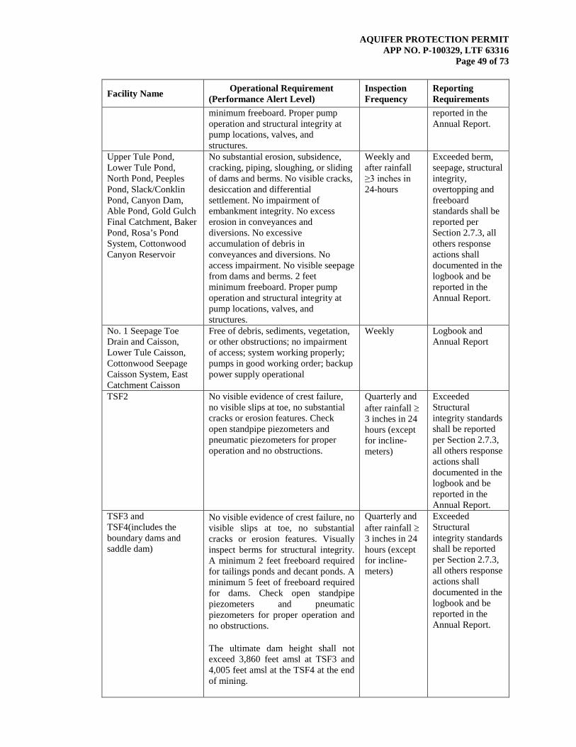
AQUIFER PROTECTION PERMIT APP NO. P-100329, LTF 63316
Page 49 of 73
Facility Name Operational Requirement (Performance Alert Level)
Inspection Frequency
Reporting Requirements
minimum freeboard. Proper pump operation and structural integrity at pump locations, valves, and structures.
reported in the Annual Report.
Upper Tule Pond, Lower Tule Pond, North Pond, Peeples Pond, Slack/Conklin Pond, Canyon Dam, Able Pond, Gold Gulch Final Catchment, Baker Pond, Rosa’s Pond System, Cottonwood Canyon Reservoir
No substantial erosion, subsidence, cracking, piping, sloughing, or sliding of dams and berms. No visible cracks, desiccation and differential settlement. No impairment of embankment integrity. No excess erosion in conveyances and diversions. No excessive accumulation of debris in conveyances and diversions. No access impairment. No visible seepage from dams and berms. 2 feet minimum freeboard. Proper pump operation and structural integrity at pump locations, valves, and structures.
Weekly and after rainfall ≥3 inches in 24-hours
Exceeded berm, seepage, structural integrity, overtopping and freeboard standards shall be reported per Section 2.7.3, all others response actions shall documented in the logbook and be reported in the Annual Report.
No. 1 Seepage Toe Drain and Caisson, Lower Tule Caisson, Cottonwood Seepage Caisson System, East Catchment Caisson
Free of debris, sediments, vegetation, or other obstructions; no impairment of access; system working properly; pumps in good working order; backup power supply operational
Weekly Logbook and Annual Report
TSF2 No visible evidence of crest failure, no visible slips at toe, no substantial cracks or erosion features. Check open standpipe piezometers and pneumatic piezometers for proper operation and no obstructions.
Quarterly and after rainfall ≥3 inches in 24 hours (except for incline-meters)
Exceeded Structural integrity standards shall be reported per Section 2.7.3, all others response actions shall documented in the logbook and be reported in the Annual Report.
TSF3 and TSF4(includes the boundary dams and saddle dam)
No visible evidence of crest failure, no visible slips at toe, no substantial cracks or erosion features. Visually inspect berms for structural integrity. A minimum 2 feet freeboard required for tailings ponds and decant ponds. A minimum 5 feet of freeboard required for dams. Check open standpipe piezometers and pneumatic piezometers for proper operation and no obstructions. The ultimate dam height shall not exceed 3,860 feet amsl at TSF3 and 4,005 feet amsl at the TSF4 at the end of mining.
Quarterly and after rainfall ≥3 inches in 24 hours (except for incline-meters)
Exceeded Structural integrity standards shall be reported per Section 2.7.3, all others response actions shall documented in the logbook and be reported in the Annual Report.

AQUIFER PROTECTION PERMIT APP NO. P-100329, LTF 63316
Page 50 of 73
Facility Name Operational Requirement (Performance Alert Level)
Inspection Frequency
Reporting Requirements
Northside Waste Rock Dumps, Southside Waste Rock Dump, 19 Extension Dump, Castle Dome Marginal Dump, North Barn Marginal Dump, Main Dump
No substantial slips at toe. No substantial evidence of crest failures. If facility has not yet been constructed, the inspections are to be performed when the facility has been constructed.
Quarterly Per Section 2.7.3
Stormwater run-on/runoff control features and berms protecting closed in-place facilities
Maintained to divert run-on and prevent stormwater from ponding on closed in-place facilities. No visible erosion or other damage that may impact berm integrity or stability.
Monthly and after a significant storm or natural disaster, regardless of operating status
Per Section 2.7.3
Freeboard in all impoundments until closure configuration results achieved and contain non-contact stormwater only
Maintain at least 2 feet of freeboard from top of berm, except in those impoundments equipped with spillway at a specific elevation that are designed to discharge to the next impoundment down line or to the outfall under a valid AZPDES permit (perform response actions per Section 2.6.2.2)
Monthly and after a significant storm or natural disaster, regardless of operating status
Per Section 2.7.3
POC Wells and Alert Wells
Well cap in place and no visible damage to casing
Quarterly Annual Report
Impoundment Fluid Level
No unexpected or sudden loss of fluid (perform response actions per Section 2.6.3.1)
Monthly and after a significant storm or natural disaster, regardless of operating status
Per Section 2.7.3
Solid Waste Landfill Cover placed over construction debris when landfill is in active use; Drainage control systems free of obstructions, breaches; nuisance control measures such as litter, vector, and fire controls in place.
Quarterly and after rainfall ≥3 inches in 24 hours
Operational response actions shall be documented in the logbook and be reported in the Annual report
Wastewater Treatment Plant
No structural damage; Distribution box free flowing; Entrance pipe clear; Effluent water clear; Air flow adequate.
Monthly and after rainfall ≥3 inches in 24 hours
Operational response actions shall be documented in the logbook and be reported in the Annual report

AQUIFER PROTECTION PERMIT APP NO. P-100329, LTF 63316
Page 51 of 73
Table 4.1-5 Pit Containment Active Monitoring
Well Name ADWR Number Latitude Longitude
Measuring Point
Elevation (ft amsl7)
Total Drilled Depth
(ft bgs8)
Screened Interval (ft bgs)
APP-1A 55-543407 33° 27’ 25” N 110° 58’ 43” W 3588.99 200 90-190 APP-1Br 55-563251 33° 27’ 25” N 110° 58’ 43” W 3590.50 460 370-450 APP-2 55-543406 33° 27’ 16” N 110° 59’ 46” W 3170.30 250 140-240 APP-3A 55-543404 33° 25’ 34” N 110° 59’ 59” W 3168.50 48 23.6-43.6 APP-3B 55-543405 33° 25’ 34” N 110° 59’ 59” W 3166.26 250 145-245 APP-4 55-543403 33° 25’ 21” N 111° 00’ 03” W 3256.29 153 45-145 APP-5A 55-543402 33° 23’ 42” N 110° 59’ 07” W 3468.41 35 25-35 APP-5B 55-553712M 33° 23’ 42” N 110° 59’ 07” W 3471.51 200 92-192 APP-6 55-543401 33° 23’ 36” N 110° 58’ 57” W 3516.00 135 24-114 APP-7 55-560644 33° 22’ 58” N 110° 59’ 25” W 3442.61 124 58-118 Domestic 1 55-640808 33° 23’ 07” N 110° 58’ 39” W 3625.00 300 –9 GTI-MW-3 55-525044 33° 23’ 13” N 110° 58’ 10”W 3878.58 81 19-79 GTI-MW-4 55-525043 33° 23’ 01” N 110° 58’ 11”W 3886.34 81 19-79 GTI-MW-5 55-526381 33° 23’ 13” N 110° 57’ 60”W 3947.45 100 50-100 Miller Springs 2 55-612310 33° 22’ 41” N 110° 58’ 10”W 3830.00 750 –
MW-04-01 – 33° 22’ 31” N 110° 58’ 09”W 3740.07 103 40-100 MW-04-02 – 33° 22’ 46” N 110° 57’ 39”W 4026.85 100 50-100 MW-04-03 – 33° 23’ 06” N 110° 58’ 36”W 3581.65 90 40-90 MW-04-04 – 33° 23’ 22” N 110° 59’ 06”W 3484.35 153 100-150 MW-04-05 – 33° 23’ 44” N 110° 58’ 27”W 3908.00 210 170-240 MW-04-06 – 33° 23’ 53” N 110° 59’ 16”W 3882.67 100 70-100
MW-04-07 – 33° 24’ 04” N 110° 58’ 42”W 4003.88 400 280.5-320.5
MW-04-09 – 33° 24’ 36” N 110° 59’ 03”W 3441.65 400 30-60 MW-04-10 – 33° 24’ 58” N 110° 58’ 42”W 4134.20 497 300-340 MW-04-12 – 33° 26’ 50” N 110° 59’ 23”W 3347.35 320 290-320 MW-04-13 – 33° 24’ 25” N 110° 58’ 36”W 4032.08 515 484-514 MW-04-15 – 33° 25’ 42” N 110° 58’ 04”W 3871.84 230 200-230 Northeast 27 – 33° 24’ 31” N 110° 57’ 28” W 4347.83 800 –
Northeast 29 – 33° 24’ 29” W 110° 57’ 19” N 4360.52 110 –
Northwest 31 – 33° 24’ 19” W 110° 58’ 17” N 3904.43 940 –
PZ-5 – 33° 23’ 55” W 110° 57’ 28” N 4065.00 – – Shop Site 2 55-612354 33° 23’ 05” W 110° 57’ 55” N 4023.37 1510 40-1510 South 34 – 33° 23’ 31” W 110° 57’ 57” N 4070.21 – – South 4 – 33° 23’ 32” W 110° 57’ 52” N 4172.00 360 – South 5B – 33° 23’ 40” W 110° 57’ 42” N 3995.00 340 – South 6 – 33° 23’ 33” W 110° 57’ 59” N 4007.10 550 – South 8 – 33° 23’ 28” W 110° 57’ 54” N 4101.58 600 – Southeast 1B – 33° 23’ 55” W 110° 57’ 37” N 4022.69 200 –
7 ft amsl = feet above mean sea level 8 ft bgs = feet below ground surface 9 (-) indicates no data

AQUIFER PROTECTION PERMIT APP NO. P-100329, LTF 63316
Page 52 of 73
Well Name ADWR Number Latitude Longitude
Measuring Point
Elevation (ft amsl7)
Total Drilled Depth
(ft bgs8)
Screened Interval (ft bgs)
Unknown Exp. 1 – 33° 23’ 59” W 110° 57’ 42” N 3950.00 – –
Unknown Exp. 2 – 33° 24’ 07” W 110° 57’ 16” N 4085.00 – –
Unknown Exp. 3 – 33° 24’ 08” W 110° 57’ 05” N – – –
Unknown B – 33° 24’ 18” W 110° 57’ 05” N 4370.00 – –
Unknown K – 33° 25’ 07” W 110° 57’ 29” N 4680.00 – –
West 32 – 33° 23’ 38” W 110° 58’ 16” N 3985.98 690 – West 33 – 33° 23’ 56” W 110° 58’ 24” N 3824.89 730 – West 35 – 33° 23’ 42” W 110° 58’ 19” N 3955.13 700 – West 36 – 33° 24’ 01” W 110° 58’ 23” N 3770.92 810 –
Parameter Monitoring Frequency
Reporting frequency Criteria for Action
Pit Containment Annually Annually
Water level measurements will be used to develop groundwater potentiometric surface maps. If groundwater flow direction towards open pit and pit containment is not demonstrated contingency requirements in Section 2.6.2.1 must be followed.
Open pit water level Annually Annually Pit water level greater than 3,450 ft amsl triggers contingency requirements.
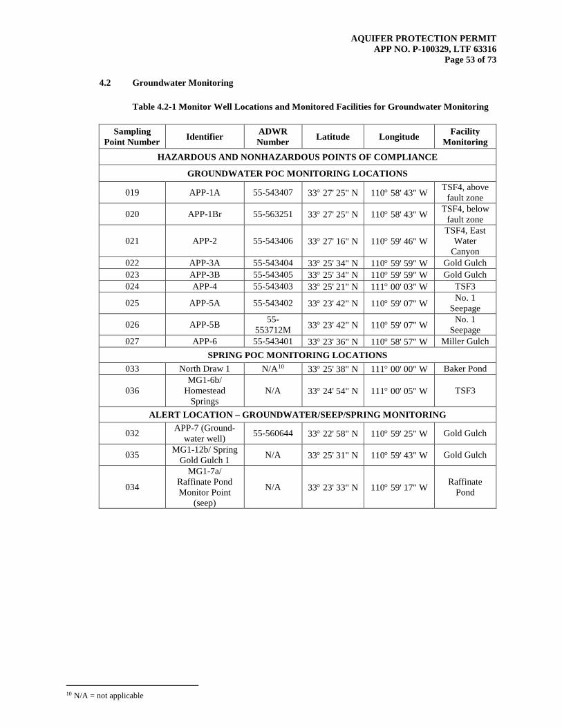
AQUIFER PROTECTION PERMIT APP NO. P-100329, LTF 63316
Page 53 of 73
4.2 Groundwater Monitoring
Table 4.2-1 Monitor Well Locations and Monitored Facilities for Groundwater Monitoring
Sampling Point Number Identifier ADWR
Number Latitude Longitude Facility Monitoring
HAZARDOUS AND NONHAZARDOUS POINTS OF COMPLIANCE
GROUNDWATER POC MONITORING LOCATIONS
019 APP-1A 55-543407 33° 27' 25" N 110° 58' 43" W TSF4, above fault zone
020 APP-1Br 55-563251 33° 27' 25" N 110° 58' 43" W TSF4, below fault zone
021 APP-2 55-543406 33° 27' 16" N 110° 59' 46" W TSF4, East
Water Canyon
022 APP-3A 55-543404 33° 25' 34" N 110° 59' 59" W Gold Gulch 023 APP-3B 55-543405 33° 25' 34" N 110° 59' 59" W Gold Gulch 024 APP-4 55-543403 33° 25' 21" N 111° 00' 03" W TSF3
025 APP-5A 55-543402 33° 23' 42" N 110° 59' 07" W No. 1 Seepage
026 APP-5B 55-553712M 33° 23' 42" N 110° 59' 07" W No. 1
Seepage 027 APP-6 55-543401 33° 23' 36" N 110° 58' 57" W Miller Gulch
SPRING POC MONITORING LOCATIONS 033 North Draw 1 N/A10 33° 25' 38" N 111° 00' 00" W Baker Pond
036 MG1-6b/
Homestead Springs
N/A 33° 24' 54" N 111° 00' 05" W TSF3
ALERT LOCATION – GROUNDWATER/SEEP/SPRING MONITORING
032 APP-7 (Ground-water well) 55-560644 33° 22' 58" N 110° 59' 25" W Gold Gulch
035 MG1-12b/ Spring Gold Gulch 1 N/A 33° 25' 31" N 110° 59' 43" W Gold Gulch
034
MG1-7a/ Raffinate Pond Monitor Point
(seep)
N/A 33° 23' 33" N 110° 59' 17" W Raffinate Pond
10 N/A = not applicable
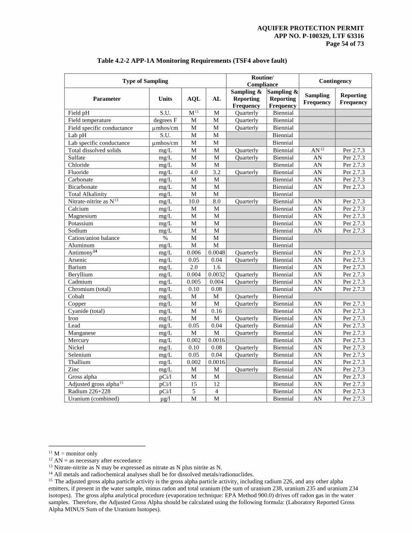
AQUIFER PROTECTION PERMIT APP NO. P-100329, LTF 63316
Page 54 of 73
Table 4.2-2 APP-1A Monitoring Requirements (TSF4 above fault)
Type of Sampling Routine/ Compliance Contingency
Parameter Units AQL AL Sampling & Reporting Frequency
Sampling & Reporting Frequency
Sampling Frequency
Reporting Frequency
Field pH S.U. M11 M Quarterly Biennial Field temperature degrees F M M Quarterly Biennial Field specific conductance µmhos/cm M M Quarterly Biennial Lab pH S.U. M M Biennial Lab specific conductance µmhos/cm M M Biennial Total dissolved solids mg/L M M Quarterly Biennial AN12 Per 2.7.3 Sulfate mg/L M M Quarterly Biennial AN Per 2.7.3 Chloride mg/L M M Biennial AN Per 2.7.3 Fluoride mg/L 4.0 3.2 Quarterly Biennial AN Per 2.7.3 Carbonate mg/L M M Biennial AN Per 2.7.3 Bicarbonate mg/L M M Biennial AN Per 2.7.3 Total Alkalinity mg/L M M Biennial Nitrate-nitrite as N13 mg/L 10.0 8.0 Quarterly Biennial AN Per 2.7.3 Calcium mg/L M M Biennial AN Per 2.7.3 Magnesium mg/L M M Biennial AN Per 2.7.3 Potassium mg/L M M Biennial AN Per 2.7.3 Sodium mg/L M M Biennial AN Per 2.7.3 Cation/anion balance % M M Biennial Aluminum mg/L M M Biennial Antimony14 mg/L 0.006 0.0048 Quarterly Biennial AN Per 2.7.3 Arsenic mg/L 0.05 0.04 Quarterly Biennial AN Per 2.7.3 Barium mg/L 2.0 1.6 Biennial AN Per 2.7.3 Beryllium mg/L 0.004 0.0032 Quarterly Biennial AN Per 2.7.3 Cadmium mg/L 0.005 0.004 Quarterly Biennial AN Per 2.7.3 Chromium (total) mg/L 0.10 0.08 Biennial AN Per 2.7.3 Cobalt mg/L M M Quarterly Biennial Copper mg/L M M Quarterly Biennial AN Per 2.7.3 Cyanide (total) mg/L M 0.16 Biennial AN Per 2.7.3 Iron mg/L M M Quarterly Biennial AN Per 2.7.3 Lead mg/L 0.05 0.04 Quarterly Biennial AN Per 2.7.3 Manganese mg/L M M Quarterly Biennial AN Per 2.7.3 Mercury mg/L 0.002 0.0016 Biennial AN Per 2.7.3 Nickel mg/L 0.10 0.08 Quarterly Biennial AN Per 2.7.3 Selenium mg/L 0.05 0.04 Quarterly Biennial AN Per 2.7.3 Thallium mg/L 0.002 0.0016 Biennial AN Per 2.7.3 Zinc mg/L M M Quarterly Biennial AN Per 2.7.3 Gross alpha pCi/l M M Biennial AN Per 2.7.3 Adjusted gross alpha15 pCi/l 15 12 Biennial AN Per 2.7.3 Radium 226+228 pCi/l 5 4 Biennial AN Per 2.7.3 Uranium (combined) µg/l M M Biennial AN Per 2.7.3
11 M = monitor only 12 AN = as necessary after exceedance 13 Nitrate-nitrite as N may be expressed as nitrate as N plus nitrite as N. 14 All metals and radiochemical analyses shall be for dissolved metals/radionuclides. 15 The adjusted gross alpha particle activity is the gross alpha particle activity, including radium 226, and any other alpha emitters, if present in the water sample, minus radon and total uranium (the sum of uranium 238, uranium 235 and uranium 234 isotopes). The gross alpha analytical procedure (evaporation technique: EPA Method 900.0) drives off radon gas in the water samples. Therefore, the Adjusted Gross Alpha should be calculated using the following formula: (Laboratory Reported Gross Alpha MINUS Sum of the Uranium Isotopes).

AQUIFER PROTECTION PERMIT APP NO. P-100329, LTF 63316
Page 55 of 73
Table 4.2-3 APP-1Br Monitoring Requirements (TSF4 below fault)
Type of Sampling Routine/ Compliance Contingency
Parameter Units AQL AL Sampling & Reporting Frequency
Sampling & Reporting Frequency
Sampling Frequency
Reporting Frequency
Field pH S.U. M16 M Quarterly Biennial Field temperature degrees F M M Quarterly Biennial Field specific conductance µmhos/cm M M Quarterly Biennial Lab pH S.U. M M Biennial Lab specific conductance µmhos/cm M M Biennial Total dissolved solids mg/L M M Quarterly Biennial AN17 Per 2.7.3 Sulfate mg/L M M Quarterly Biennial AN Per 2.7.3 Chloride mg/L M M Biennial AN Per 2.7.3 Fluoride mg/L 4.0 3.2 Quarterly Biennial AN Per 2.7.3 Carbonate mg/L M M Biennial AN Per 2.7.3 Bicarbonate mg/L M M Biennial AN Per 2.7.3 Total Alkalinity mg/L M M Biennial Nitrate-nitrite as N18 mg/L 10.0 8 Quarterly Biennial AN Per 2.7.3 Calcium mg/L M M Biennial AN Per 2.7.3 Magnesium mg/L M M Biennial AN Per 2.7.3 Potassium mg/L M M Biennial AN Per 2.7.3 Sodium mg/L M M Biennial AN Per 2.7.3 Cation/anion balance % M M Biennial Aluminum mg/L M M Biennial Antimony19 mg/L 0.006 0.0048 Quarterly Biennial AN Per 2.7.3 Arsenic mg/L 0.05 0.04 Quarterly Biennial AN Per 2.7.3 Barium mg/L 2.0 1.6 Biennial AN Per 2.7.3 Beryllium mg/L 0.004 0.0032 Quarterly Biennial AN Per 2.7.3 Cadmium mg/L 0.005 0.004 Quarterly Biennial AN Per 2.7.3 Chromium (total) mg/L 0.10 0.08 Biennial AN Per 2.7.3 Cobalt mg/L M M Quarterly Biennial Copper mg/L M M Quarterly Biennial AN Per 2.7.3 Cyanide (total) mg/L M 0.16 Biennial AN Per 2.7.3 Iron mg/L M M Quarterly Biennial AN Per 2.7.3 Lead mg/L 0.054 M Quarterly Biennial AN Per 2.7.3 Manganese mg/L M M Quarterly Biennial AN Per 2.7.3 Mercury mg/L 0.002 0.0016 Biennial AN Per 2.7.3 Nickel mg/L 0.10 0.08 Quarterly Biennial AN Per 2.7.3 Selenium mg/L 0.05 0.04 Quarterly Biennial AN Per 2.7.3 Thallium mg/L 0.002 0.0016 Biennial AN Per 2.7.3 Zinc mg/L M M Quarterly Biennial AN Per 2.7.3 Gross alpha pCi/l M M Biennial AN Per 2.7.3 Adjusted gross alpha20 pCi/l 15 12 Biennial AN Per 2.7.3 Radium 226 + 22821 pCi/l 5 4 Biennial AN Per 2.7.3 Uranium (combined) µg/l M M Biennial AN Per 2.7.3
16 M = monitor only 17 AN = as necessary after exceedance 18 Nitrate-nitrite as N may be expressed as nitrate as N plus nitrite as N. 19 All metals and radiochemical analyses shall be for dissolved metals/radionuclides. 20. The adjusted gross alpha particle activity is the gross alpha particle activity, including radium 226, and any other alpha
emitters, if present in the water sample, minus radon and total uranium (the sum of uranium 238, uranium 235 and uranium 234 isotopes). The gross alpha analytical procedure (evaporation technique: EPA Method 900.0) drives off radon gas in the water samples. Therefore, the Adjusted Gross Alpha should be calculated using the following formula: (Laboratory Reported Gross Alpha MINUS Sum of the Uranium Isotopes).
21 Total radium is expressed as the sum of radium-226 plus radium-228.

AQUIFER PROTECTION PERMIT APP NO. P-100329, LTF 63316
Page 56 of 73
Table 4.2-4 APP-2 Monitoring Requirements (TSF4 Eastwater Canyon)
Type of Sampling Routine/ Compliance Contingency
Parameter Units AQL AL Sampling & Reporting Frequency
Sampling & Reporting Frequency
Sampling Frequency
Reporting Frequency
Field pH S.U. M22 M Quarterly Biennial Field temperature degrees F M M Quarterly Biennial Field specific conductance µmhos/cm M M Quarterly Biennial Lab pH S.U. M M Biennial Lab specific conductance µmhos/cm M M Biennial Total dissolved solids mg/L M M Quarterly Biennial AN23 Per 2.7.3 Sulfate mg/L M M Quarterly Biennial AN Per 2.7.3 Chloride mg/L M M Biennial AN Per 2.7.3 Fluoride mg/L 4.0 3.2 Quarterly Biennial AN Per 2.7.3 Carbonate mg/L M M Biennial AN Per 2.7.3 Bicarbonate mg/L M M Biennial AN Per 2.7.3 Total Alkalinity mg/L M M Biennial Nitrate-nitrite as N24 mg/L 10.0 8.0 Quarterly Biennial AN Per 2.7.3 Calcium mg/L M M Biennial AN Per 2.7.3 Magnesium mg/L M M Biennial AN Per 2.7.3 Potassium mg/L M M Biennial AN Per 2.7.3 Sodium mg/L M M Biennial AN Per 2.7.3 Cation/anion balance % M M Biennial Aluminum mg/L M M Biennial Antimony25 mg/L 0.006 0.0048 Quarterly Biennial AN Per 2.7.3 Arsenic mg/L 0.05 0.04 Quarterly Biennial AN Per 2.7.3 Barium mg/L 2.0 1.6 Biennial AN Per 2.7.3 Beryllium mg/L 0.004 0.0032 Quarterly Biennial AN Per 2.7.3 Cadmium mg/L 0.005 0.004 Quarterly Biennial AN Per 2.7.3 Chromium (total) mg/L 0.10 0.08 Biennial AN Per 2.7.3 Cobalt mg/L M M Quarterly Biennial Copper mg/L M M Quarterly Biennial AN Per 2.7.3 Cyanide (total) mg/L M 0.16 Biennial AN Per 2.7.3 Iron mg/L M M Quarterly Biennial AN Per 2.7.3 Lead mg/L 0.05 0.04 Quarterly Biennial AN Per 2.7.3 Manganese mg/L M M Quarterly Biennial AN Per 2.7.3 Mercury mg/L 0.002 0.0016 Biennial AN Per 2.7.3 Nickel mg/L 0.10 0.08 Quarterly Biennial AN Per 2.7.3 Selenium mg/L 0.05 0.04 Quarterly Biennial AN Per 2.7.3 Thallium mg/L 0.002 0.0016 Biennial AN Per 2.7.3 Zinc mg/L M M Quarterly Biennial AN Per 2.7.3 Gross alpha pCi/l M M Biennial AN Per 2.7.3 Adjusted gross alpha26 pCi/l 15 12 Biennial AN Per 2.7.3 Radium 226 + 22827 pCi/l 5 4 Biennial AN Per 2.7.3 Uranium (combined) µg/l M M Biennial AN Per 2.7.3
22 M = monitor only 23 AN = as necessary after exceedance 24 Nitrate-nitrite as N may be expressed as nitrate as N plus nitrite as N. 25 All metals and radiochemical analyses shall be for dissolved metals/radionuclides. 26 The adjusted gross alpha particle activity is the gross alpha particle activity, including radium 226, and any other alpha
emitters, if present in the water sample, minus radon and total uranium (the sum of uranium 238, uranium 235 and uranium 234 isotopes). The gross alpha analytical procedure (evaporation technique: EPA Method 900.0) drives off radon gas in the water samples. Therefore, the Adjusted Gross Alpha should be calculated using the following formula: (Laboratory Reported Gross Alpha MINUS Sum of the Uranium Isotopes).
27 Total radium is expressed as the sum of radium-226 plus radium-228.
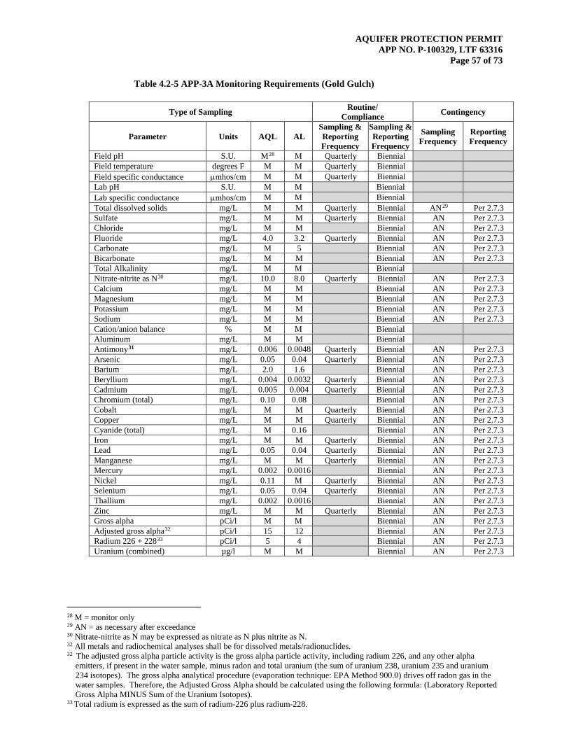
AQUIFER PROTECTION PERMIT APP NO. P-100329, LTF 63316
Page 57 of 73
Table 4.2-5 APP-3A Monitoring Requirements (Gold Gulch)
Type of Sampling Routine/ Compliance Contingency
Parameter Units AQL AL Sampling & Reporting Frequency
Sampling & Reporting Frequency
Sampling Frequency
Reporting Frequency
Field pH S.U. M28 M Quarterly Biennial Field temperature degrees F M M Quarterly Biennial Field specific conductance µmhos/cm M M Quarterly Biennial Lab pH S.U. M M Biennial Lab specific conductance µmhos/cm M M Biennial Total dissolved solids mg/L M M Quarterly Biennial AN29 Per 2.7.3 Sulfate mg/L M M Quarterly Biennial AN Per 2.7.3 Chloride mg/L M M Biennial AN Per 2.7.3 Fluoride mg/L 4.0 3.2 Quarterly Biennial AN Per 2.7.3 Carbonate mg/L M 5 Biennial AN Per 2.7.3 Bicarbonate mg/L M M Biennial AN Per 2.7.3 Total Alkalinity mg/L M M Biennial Nitrate-nitrite as N30 mg/L 10.0 8.0 Quarterly Biennial AN Per 2.7.3 Calcium mg/L M M Biennial AN Per 2.7.3 Magnesium mg/L M M Biennial AN Per 2.7.3 Potassium mg/L M M Biennial AN Per 2.7.3 Sodium mg/L M M Biennial AN Per 2.7.3 Cation/anion balance % M M Biennial Aluminum mg/L M M Biennial Antimony31 mg/L 0.006 0.0048 Quarterly Biennial AN Per 2.7.3 Arsenic mg/L 0.05 0.04 Quarterly Biennial AN Per 2.7.3 Barium mg/L 2.0 1.6 Biennial AN Per 2.7.3 Beryllium mg/L 0.004 0.0032 Quarterly Biennial AN Per 2.7.3 Cadmium mg/L 0.005 0.004 Quarterly Biennial AN Per 2.7.3 Chromium (total) mg/L 0.10 0.08 Biennial AN Per 2.7.3 Cobalt mg/L M M Quarterly Biennial AN Per 2.7.3 Copper mg/L M M Quarterly Biennial AN Per 2.7.3 Cyanide (total) mg/L M 0.16 Biennial AN Per 2.7.3 Iron mg/L M M Quarterly Biennial AN Per 2.7.3 Lead mg/L 0.05 0.04 Quarterly Biennial AN Per 2.7.3 Manganese mg/L M M Quarterly Biennial AN Per 2.7.3 Mercury mg/L 0.002 0.0016 Biennial AN Per 2.7.3 Nickel mg/L 0.11 M Quarterly Biennial AN Per 2.7.3 Selenium mg/L 0.05 0.04 Quarterly Biennial AN Per 2.7.3 Thallium mg/L 0.002 0.0016 Biennial AN Per 2.7.3 Zinc mg/L M M Quarterly Biennial AN Per 2.7.3 Gross alpha pCi/l M M Biennial AN Per 2.7.3 Adjusted gross alpha32 pCi/l 15 12 Biennial AN Per 2.7.3 Radium 226 + 22833 pCi/l 5 4 Biennial AN Per 2.7.3 Uranium (combined) µg/l M M Biennial AN Per 2.7.3
28 M = monitor only 29 AN = as necessary after exceedance 30 Nitrate-nitrite as N may be expressed as nitrate as N plus nitrite as N. 32 All metals and radiochemical analyses shall be for dissolved metals/radionuclides. 32 The adjusted gross alpha particle activity is the gross alpha particle activity, including radium 226, and any other alpha
emitters, if present in the water sample, minus radon and total uranium (the sum of uranium 238, uranium 235 and uranium 234 isotopes). The gross alpha analytical procedure (evaporation technique: EPA Method 900.0) drives off radon gas in the water samples. Therefore, the Adjusted Gross Alpha should be calculated using the following formula: (Laboratory Reported Gross Alpha MINUS Sum of the Uranium Isotopes).
33 Total radium is expressed as the sum of radium-226 plus radium-228.
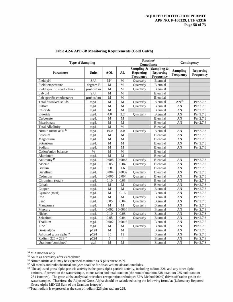
AQUIFER PROTECTION PERMIT APP NO. P-100329, LTF 63316
Page 58 of 73
Table 4.2-6 APP-3B Monitoring Requirements (Gold Gulch)
Type of Sampling Routine/ Compliance Contingency
Parameter Units AQL AL Sampling & Reporting Frequency
Sampling & Reporting Frequency
Sampling Frequency
Reporting Frequency
Field pH S.U. M34 M Quarterly Biennial Field temperature degrees F M M Quarterly Biennial Field specific conductance µmhos/cm M M Quarterly Biennial Lab pH S.U. M M Biennial Lab specific conductance µmhos/cm M M Biennial Total dissolved solids mg/L M M Quarterly Biennial AN35 Per 2.7.3 Sulfate mg/L M M Quarterly Biennial AN Per 2.7.3 Chloride mg/L M M Biennial AN Per 2.7.3 Fluoride mg/L 4.0 3.2 Quarterly Biennial AN Per 2.7.3 Carbonate mg/L M M Biennial AN Per 2.7.3 Bicarbonate mg/L M M Biennial AN Per 2.7.3 Total Alkalinity mg/L M M Biennial Nitrate-nitrite as N36 mg/L 10.0 8.0 Quarterly Biennial AN Per 2.7.3 Calcium mg/L M M Biennial AN Per 2.7.3 Magnesium mg/L M M Biennial AN Per 2.7.3 Potassium mg/L M M Biennial AN Per 2.7.3 Sodium mg/L M M Biennial AN Per 2.7.3 Cation/anion balance % M M Biennial Aluminum mg/L M M Biennial Antimony37 mg/L 0.006 0.0048 Quarterly Biennial AN Per 2.7.3 Arsenic mg/L 0.05 0.04 Quarterly Biennial AN Per 2.7.3 Barium mg/L 2.0 1.6 Biennial AN Per 2.7.3 Beryllium mg/L 0.004 0.0032 Quarterly Biennial AN Per 2.7.3 Cadmium mg/L 0.005 0.004 Quarterly Biennial AN Per 2.7.3 Chromium (total) mg/L 0.10 0.08 Biennial AN Per 2.7.3 Cobalt mg/L M M Quarterly Biennial AN Per 2.7.3 Copper mg/L M M Quarterly Biennial AN Per 2.7.3 Cyanide (total) mg/L M 0.16 Biennial AN Per 2.7.3 Iron mg/L M M Quarterly Biennial AN Per 2.7.3 Lead mg/L 0.05 0.04 Quarterly Biennial AN Per 2.7.3 Manganese mg/L M M Quarterly Biennial AN Per 2.7.3 Mercury mg/L 0.002 0.0016 Biennial AN Per 2.7.3 Nickel mg/L 0.10 0.08 Quarterly Biennial AN Per 2.7.3 Selenium mg/L 0.05 0.04 Quarterly Biennial AN Per 2.7.3 Thallium mg/L 0.002 0.0016 Biennial AN Per 2.7.3 Zinc mg/L M M Quarterly Biennial AN Per 2.7.3 Gross alpha pCi/l M M Biennial AN Per 2.7.3 Adjusted gross alpha38 pCi/l 15 12 Biennial AN Per 2.7.3 Radium 226 + 22839 pCi/l 5 4 Biennial AN Per 2.7.3 Uranium (combined) µg/l M M Biennial AN Per 2.7.3
34 M = monitor only 35 AN = as necessary after exceedance 36 Nitrate-nitrite as N may be expressed as nitrate as N plus nitrite as N. 37 All metals and radiochemical analyses shall be for dissolved metals/radionuclides. 38 The adjusted gross alpha particle activity is the gross alpha particle activity, including radium 226, and any other alpha
emitters, if present in the water sample, minus radon and total uranium (the sum of uranium 238, uranium 235 and uranium 234 isotopes). The gross alpha analytical procedure (evaporation technique: EPA Method 900.0) drives off radon gas in the water samples. Therefore, the Adjusted Gross Alpha should be calculated using the following formula: (Laboratory Reported Gross Alpha MINUS Sum of the Uranium Isotopes).
39 Total radium is expressed as the sum of radium-226 plus radium-228.

AQUIFER PROTECTION PERMIT APP NO. P-100329, LTF 63316
Page 59 of 73
Table 4.2-7 APP-4 Monitoring Requirements (TSF3)
Type of Sampling Routine/ Compliance Contingency
Parameter Units AQL AL Sampling & Reporting Frequency
Sampling & Reporting Frequency
Sampling Frequency
Reporting Frequency
Field pH S.U. M40 M Quarterly Biennial Field temperature degrees F M M Quarterly Biennial Field specific conductance µmhos/cm M M Quarterly Biennial Lab pH S.U. M M Biennial Lab specific conductance µmhos/cm M M Biennial Total dissolved solids mg/L M M Quarterly Biennial AN41 Per 2.7.3 Sulfate mg/L M M Quarterly Biennial AN Per 2.7.3 Chloride mg/L M M Biennial AN Per 2.7.3 Fluoride mg/L 4.0 3.2 Quarterly Biennial AN Per 2.7.3 Carbonate mg/L M M Biennial AN Per 2.7.3 Bicarbonate mg/L M M Biennial AN Per 2.7.3 Total Alkalinity mg/L M M Biennial Nitrate-nitrite as N42 mg/L 10.0 8.0 Quarterly Biennial AN Per 2.7.3 Calcium mg/L M M Biennial AN Per 2.7.3 Magnesium mg/L M M Biennial AN Per 2.7.3 Potassium mg/L M M Biennial AN Per 2.7.3 Sodium mg/L M M Biennial AN Per 2.7.3 Cation/anion balance % M M Biennial Aluminum mg/L M M Biennial AN Per 2.7.3 Antimony43 mg/L 0.006 0.0048 Quarterly Biennial AN Per 2.7.3 Arsenic mg/L 0.05 0.04 Quarterly Biennial AN Per 2.7.3 Barium mg/L 2.0 1.6 Biennial AN Per 2.7.3 Beryllium mg/L 0.004 0.0032 Quarterly Biennial AN Per 2.7.3 Cadmium mg/L 0.005 0.004 Quarterly Biennial AN Per 2.7.3 Chromium (total) mg/L 0.10 0.08 Biennial AN Per 2.7.3 Cobalt mg/L M M Quarterly Biennial AN Per 2.7.3 Copper mg/L M M Quarterly Biennial AN Per 2.7.3 Cyanide (total) mg/L M 0.16 Biennial AN Per 2.7.3 Iron mg/L M M Quarterly Biennial AN Per 2.7.3 Lead mg/L 0.05 0.04 Biennial AN Per 2.7.3 Manganese mg/L M M Quarterly Biennial AN Per 2.7.3 Mercury mg/L 0.002 0.0016 Biennial AN Per 2.7.3 Nickel mg/L 0.10 0.08 Biennial AN Per 2.7.3 Selenium mg/L 0.05 0.04 Quarterly Biennial AN Per 2.7.3 Thallium mg/L 0.002 0.0016 Biennial AN Per 2.7.3 Zinc mg/L M M Quarterly Biennial AN Per 2.7.3 Gross alpha pCi/l M M Biennial AN Per 2.7.3 Adjusted gross alpha44 pCi/l 15 12 Biennial AN Per 2.7.3 Radium 226 + 22845 pCi/l 5 4 Biennial AN Per 2.7.3 Uranium (combined) µg/l M M Biennial AN Per 2.7.3
40 M = monitor only 41 AN = as necessary after exceedance 42 Nitrate-nitrite as N may be expressed as nitrate as N plus nitrite as N. 43 All metals and radiochemical analyses shall be for dissolved metals/radionuclides. 44 The adjusted gross alpha particle activity is the gross alpha particle activity, including radium 226, and any other alpha
emitters, if present in the water sample, minus radon and total uranium (the sum of uranium 238, uranium 235 and uranium 234 isotopes). The gross alpha analytical procedure (evaporation technique: EPA Method 900.0) drives off radon gas in the water samples. Therefore, the Adjusted Gross Alpha should be calculated using the following formula: (Laboratory Reported Gross Alpha MINUS Sum of the Uranium Isotopes).
45 Total radium is expressed as the sum of radium-226 plus radium-228.
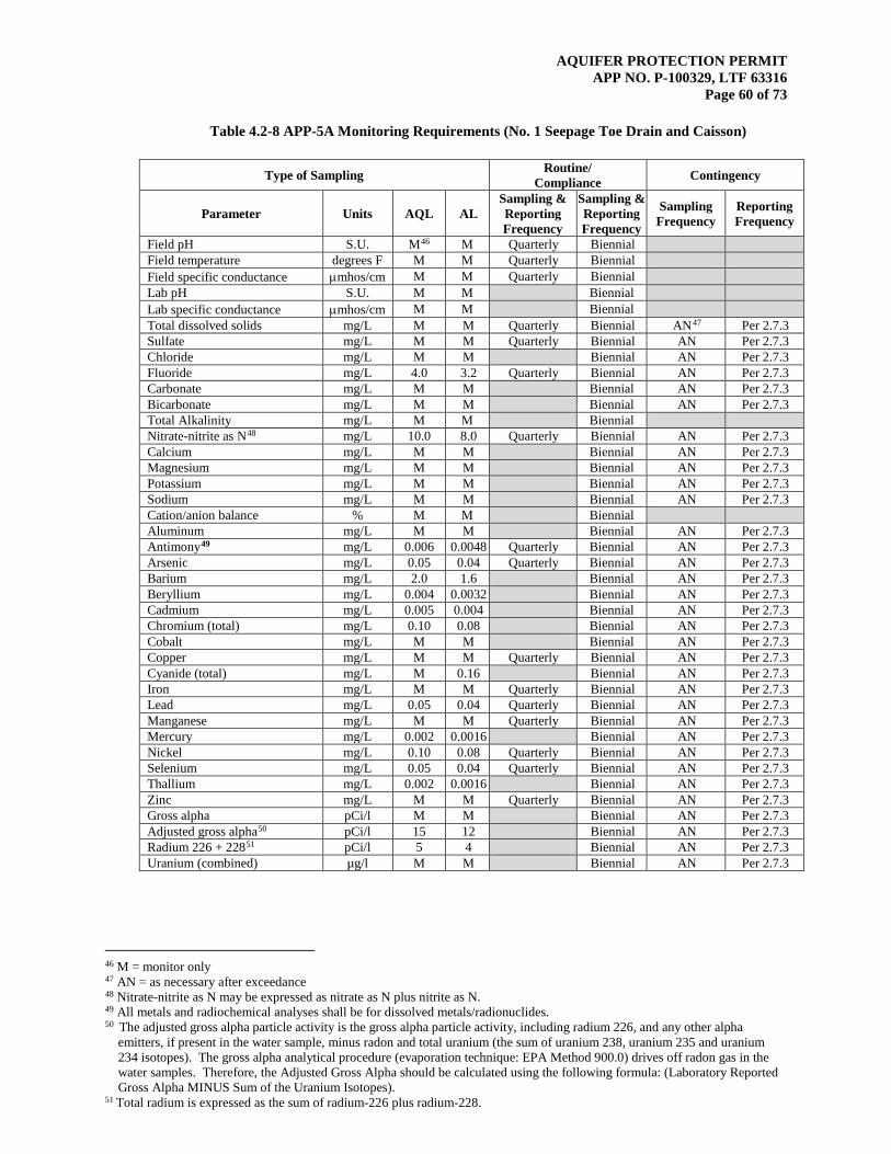
AQUIFER PROTECTION PERMIT APP NO. P-100329, LTF 63316
Page 60 of 73
Table 4.2-8 APP-5A Monitoring Requirements (No. 1 Seepage Toe Drain and Caisson)
Type of Sampling Routine/ Compliance Contingency
Parameter Units AQL AL Sampling & Reporting Frequency
Sampling & Reporting Frequency
Sampling Frequency
Reporting Frequency
Field pH S.U. M46 M Quarterly Biennial Field temperature degrees F M M Quarterly Biennial Field specific conductance µmhos/cm M M Quarterly Biennial Lab pH S.U. M M Biennial Lab specific conductance µmhos/cm M M Biennial Total dissolved solids mg/L M M Quarterly Biennial AN47 Per 2.7.3 Sulfate mg/L M M Quarterly Biennial AN Per 2.7.3 Chloride mg/L M M Biennial AN Per 2.7.3 Fluoride mg/L 4.0 3.2 Quarterly Biennial AN Per 2.7.3 Carbonate mg/L M M Biennial AN Per 2.7.3 Bicarbonate mg/L M M Biennial AN Per 2.7.3 Total Alkalinity mg/L M M Biennial Nitrate-nitrite as N48 mg/L 10.0 8.0 Quarterly Biennial AN Per 2.7.3 Calcium mg/L M M Biennial AN Per 2.7.3 Magnesium mg/L M M Biennial AN Per 2.7.3 Potassium mg/L M M Biennial AN Per 2.7.3 Sodium mg/L M M Biennial AN Per 2.7.3 Cation/anion balance % M M Biennial Aluminum mg/L M M Biennial AN Per 2.7.3 Antimony49 mg/L 0.006 0.0048 Quarterly Biennial AN Per 2.7.3 Arsenic mg/L 0.05 0.04 Quarterly Biennial AN Per 2.7.3 Barium mg/L 2.0 1.6 Biennial AN Per 2.7.3 Beryllium mg/L 0.004 0.0032 Biennial AN Per 2.7.3 Cadmium mg/L 0.005 0.004 Biennial AN Per 2.7.3 Chromium (total) mg/L 0.10 0.08 Biennial AN Per 2.7.3 Cobalt mg/L M M Biennial AN Per 2.7.3 Copper mg/L M M Quarterly Biennial AN Per 2.7.3 Cyanide (total) mg/L M 0.16 Biennial AN Per 2.7.3 Iron mg/L M M Quarterly Biennial AN Per 2.7.3 Lead mg/L 0.05 0.04 Quarterly Biennial AN Per 2.7.3 Manganese mg/L M M Quarterly Biennial AN Per 2.7.3 Mercury mg/L 0.002 0.0016 Biennial AN Per 2.7.3 Nickel mg/L 0.10 0.08 Quarterly Biennial AN Per 2.7.3 Selenium mg/L 0.05 0.04 Quarterly Biennial AN Per 2.7.3 Thallium mg/L 0.002 0.0016 Biennial AN Per 2.7.3 Zinc mg/L M M Quarterly Biennial AN Per 2.7.3 Gross alpha pCi/l M M Biennial AN Per 2.7.3 Adjusted gross alpha50 pCi/l 15 12 Biennial AN Per 2.7.3 Radium 226 + 22851 pCi/l 5 4 Biennial AN Per 2.7.3 Uranium (combined) µg/l M M Biennial AN Per 2.7.3
46 M = monitor only 47 AN = as necessary after exceedance 48 Nitrate-nitrite as N may be expressed as nitrate as N plus nitrite as N. 49 All metals and radiochemical analyses shall be for dissolved metals/radionuclides. 50 The adjusted gross alpha particle activity is the gross alpha particle activity, including radium 226, and any other alpha
emitters, if present in the water sample, minus radon and total uranium (the sum of uranium 238, uranium 235 and uranium 234 isotopes). The gross alpha analytical procedure (evaporation technique: EPA Method 900.0) drives off radon gas in the water samples. Therefore, the Adjusted Gross Alpha should be calculated using the following formula: (Laboratory Reported Gross Alpha MINUS Sum of the Uranium Isotopes).
51 Total radium is expressed as the sum of radium-226 plus radium-228.

AQUIFER PROTECTION PERMIT APP NO. P-100329, LTF 63316
Page 61 of 73
Table 4.2-9 APP-5B Monitoring Requirements (No. 1 Seepage Toe Drain and Caisson)
Type of Sampling Routine/ Compliance Contingency
Parameter Units AQL AL Sampling & Reporting Frequency
Sampling & Reporting Frequency
Sampling Frequency
Reporting Frequency
Field pH S.U. M52 M Quarterly Biennial Field temperature degrees F M M Quarterly Biennial Field specific conductance µmhos/cm M M Quarterly Biennial Lab pH S.U. M M Biennial Lab specific conductance µmhos/cm M M Biennial Total dissolved solids mg/L M M Quarterly Biennial AN53 Per 2.7.3 Sulfate mg/L M M Quarterly Biennial AN Per 2.7.3 Chloride mg/L M M Biennial AN Per 2.7.3 Fluoride mg/L 4.0 3.2 Quarterly Biennial AN Per 2.7.3 Carbonate mg/L M M Biennial AN Per 2.7.3 Bicarbonate mg/L M M Biennial AN Per 2.7.3 Total Alkalinity mg/L M M Biennial Nitrate-nitrite as N54 mg/L 10.0 8.0 Quarterly Biennial AN Per 2.7.3 Calcium mg/L M M Biennial AN Per 2.7.3 Magnesium mg/L M M Biennial AN Per 2.7.3 Potassium mg/L M M Biennial AN Per 2.7.3 Sodium mg/L M M Biennial AN Per 2.7.3 Cation/anion balance % M M Biennial Aluminum mg/L M M Biennial Antimony55 mg/L 0.006 0.0048 Quarterly Biennial AN Per 2.7.3 Arsenic mg/L 0.05 0.04 Quarterly Biennial AN Per 2.7.3 Barium mg/L 2.0 1.6 Biennial AN Per 2.7.3 Beryllium mg/L 0.004 0.0032 Quarterly Biennial AN Per 2.7.3 Cadmium mg/L 0.005 0.004 Quarterly Biennial AN Per 2.7.3 Chromium (total) mg/L 0.10 0.08 Biennial AN Per 2.7.3 Cobalt mg/L M 0.25 Quarterly Biennial AN Per 2.7.3 Copper mg/L M 0.10 Quarterly Biennial AN Per 2.7.3 Cyanide (total) mg/L M 0.16 Biennial AN Per 2.7.3 Iron mg/L M 4.3 Quarterly Biennial AN Per 2.7.3 Lead mg/L 0.05 0.04 Quarterly Biennial AN Per 2.7.3 Manganese mg/L M 0.25 Quarterly Biennial AN Per 2.7.3 Mercury mg/L 0.002 0.0016 Biennial AN Per 2.7.3 Nickel mg/L 0.10 0.08 Quarterly Biennial AN Per 2.7.3 Selenium mg/L 0.05 0.04 Quarterly Biennial AN Per 2.7.3 Thallium mg/L 0.002 0.0016 Biennial AN Per 2.7.3 Zinc mg/L M M Quarterly Biennial AN Per 2.7.3 Gross alpha pCi/l M M Biennial AN Per 2.7.3 Adjusted gross alpha56 pCi/l 15 12 Biennial AN Per 2.7.3 Radium 226 + 22857 pCi/l 5 4 Biennial AN Per 2.7.3 Uranium (combined) µg/l M M Biennial AN Per 2.7.3
52 M = monitor only 53 AN = as necessary after exceedance 54 Nitrate-nitrite as N may be expressed as nitrate as N plus nitrite as N. 55 All metals and radiochemical analyses shall be for dissolved metals/radionuclides. 56 The adjusted gross alpha particle activity is the gross alpha particle activity, including radium 226, and any other alpha
emitters, if present in the water sample, minus radon and total uranium (the sum of uranium 238, uranium 235 and uranium 234 isotopes). The gross alpha analytical procedure (evaporation technique: EPA Method 900.0) drives off radon gas in the water samples. Therefore, the Adjusted Gross Alpha should be calculated using the following formula: (Laboratory Reported Gross Alpha MINUS Sum of the Uranium Isotopes).
57 Total radium is expressed as the sum of radium-226 plus radium-228.
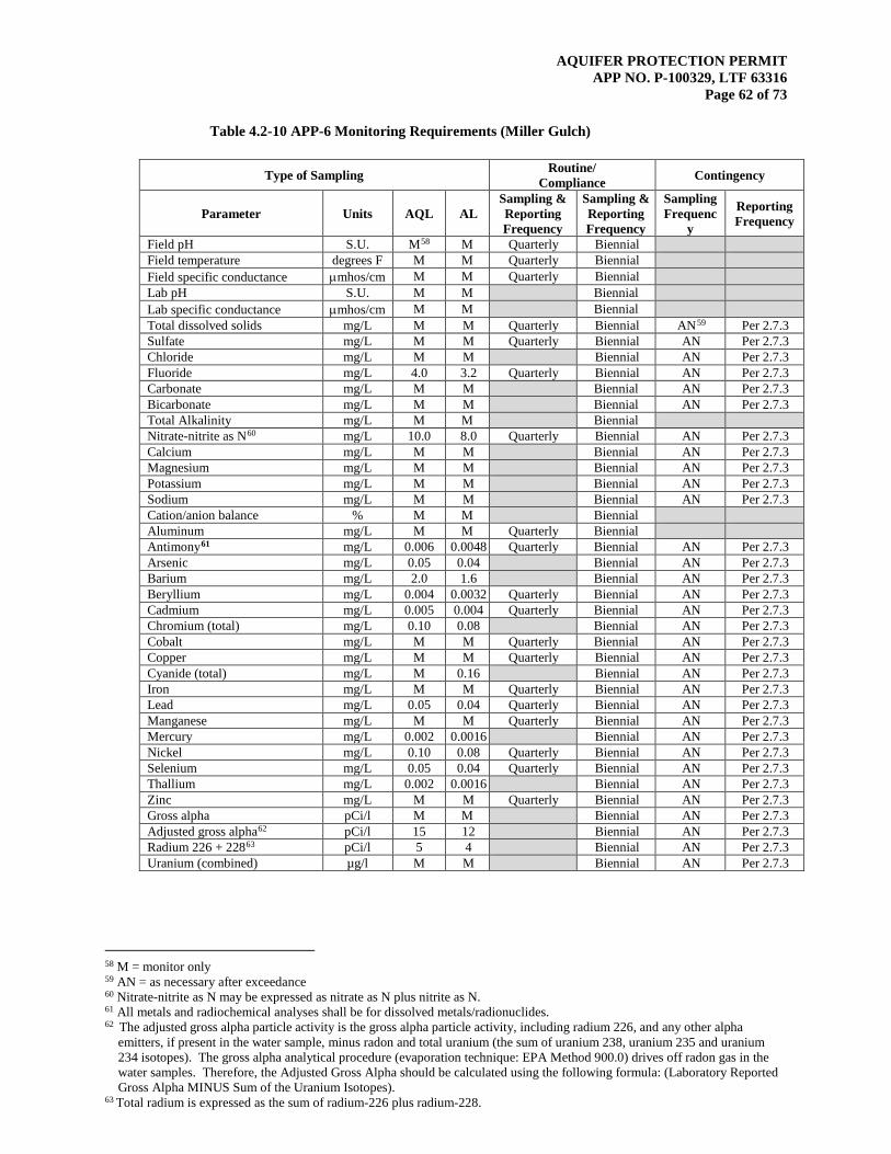
AQUIFER PROTECTION PERMIT APP NO. P-100329, LTF 63316
Page 62 of 73
Table 4.2-10 APP-6 Monitoring Requirements (Miller Gulch)
Type of Sampling Routine/ Compliance Contingency
Parameter Units AQL AL Sampling & Reporting Frequency
Sampling & Reporting Frequency
Sampling Frequenc
y
Reporting Frequency
Field pH S.U. M58 M Quarterly Biennial Field temperature degrees F M M Quarterly Biennial Field specific conductance µmhos/cm M M Quarterly Biennial Lab pH S.U. M M Biennial Lab specific conductance µmhos/cm M M Biennial Total dissolved solids mg/L M M Quarterly Biennial AN59 Per 2.7.3 Sulfate mg/L M M Quarterly Biennial AN Per 2.7.3 Chloride mg/L M M Biennial AN Per 2.7.3 Fluoride mg/L 4.0 3.2 Quarterly Biennial AN Per 2.7.3 Carbonate mg/L M M Biennial AN Per 2.7.3 Bicarbonate mg/L M M Biennial AN Per 2.7.3 Total Alkalinity mg/L M M Biennial Nitrate-nitrite as N60 mg/L 10.0 8.0 Quarterly Biennial AN Per 2.7.3 Calcium mg/L M M Biennial AN Per 2.7.3 Magnesium mg/L M M Biennial AN Per 2.7.3 Potassium mg/L M M Biennial AN Per 2.7.3 Sodium mg/L M M Biennial AN Per 2.7.3 Cation/anion balance % M M Biennial Aluminum mg/L M M Quarterly Biennial Antimony61 mg/L 0.006 0.0048 Quarterly Biennial AN Per 2.7.3 Arsenic mg/L 0.05 0.04 Biennial AN Per 2.7.3 Barium mg/L 2.0 1.6 Biennial AN Per 2.7.3 Beryllium mg/L 0.004 0.0032 Quarterly Biennial AN Per 2.7.3 Cadmium mg/L 0.005 0.004 Quarterly Biennial AN Per 2.7.3 Chromium (total) mg/L 0.10 0.08 Biennial AN Per 2.7.3 Cobalt mg/L M M Quarterly Biennial AN Per 2.7.3 Copper mg/L M M Quarterly Biennial AN Per 2.7.3 Cyanide (total) mg/L M 0.16 Biennial AN Per 2.7.3 Iron mg/L M M Quarterly Biennial AN Per 2.7.3 Lead mg/L 0.05 0.04 Quarterly Biennial AN Per 2.7.3 Manganese mg/L M M Quarterly Biennial AN Per 2.7.3 Mercury mg/L 0.002 0.0016 Biennial AN Per 2.7.3 Nickel mg/L 0.10 0.08 Quarterly Biennial AN Per 2.7.3 Selenium mg/L 0.05 0.04 Quarterly Biennial AN Per 2.7.3 Thallium mg/L 0.002 0.0016 Biennial AN Per 2.7.3 Zinc mg/L M M Quarterly Biennial AN Per 2.7.3 Gross alpha pCi/l M M Biennial AN Per 2.7.3 Adjusted gross alpha62 pCi/l 15 12 Biennial AN Per 2.7.3 Radium 226 + 22863 pCi/l 5 4 Biennial AN Per 2.7.3 Uranium (combined) µg/l M M Biennial AN Per 2.7.3
58 M = monitor only 59 AN = as necessary after exceedance 60 Nitrate-nitrite as N may be expressed as nitrate as N plus nitrite as N. 61 All metals and radiochemical analyses shall be for dissolved metals/radionuclides. 62 The adjusted gross alpha particle activity is the gross alpha particle activity, including radium 226, and any other alpha
emitters, if present in the water sample, minus radon and total uranium (the sum of uranium 238, uranium 235 and uranium 234 isotopes). The gross alpha analytical procedure (evaporation technique: EPA Method 900.0) drives off radon gas in the water samples. Therefore, the Adjusted Gross Alpha should be calculated using the following formula: (Laboratory Reported Gross Alpha MINUS Sum of the Uranium Isotopes).
63 Total radium is expressed as the sum of radium-226 plus radium-228.

AQUIFER PROTECTION PERMIT APP NO. P-100329, LTF 63316
Page 63 of 73
Table 4.2-11 North Draw 1 Monitoring Requirements
Type of Sampling Routine/ Compliance Contingency
Parameter Units AQL AL Sampling & Reporting Frequency
Sampling & Reporting Frequency
Sampling Frequency
Reporting Frequency
Field pH S.U. M64 M Quarterly Biennial Field temperature degrees F M M Quarterly Biennial Field specific conductance µmhos/cm M M Quarterly Biennial Lab pH S.U. M M Biennial Lab specific conductance µmhos/cm M M Biennial Total dissolved solids mg/L M M Quarterly Biennial Sulfate mg/L M M Quarterly Biennial Chloride mg/L M M Biennial Fluoride mg/L 4 3.2 Biennial AN65 Per 2.7.3 Carbonate mg/L M M Biennial Bicarbonate mg/L M M Biennial Total Alkalinity mg/L M M Biennial Nitrate-nitrite as N66 mg/L 10.0 8.0 Quarterly Biennial AN Per 2.7.3 Calcium mg/L M M Biennial Magnesium mg/L M M Biennial Potassium mg/L M M Biennial Sodium mg/L M M Biennial Cation/anion balance % M M Biennial Aluminum mg/L M M Biennial Antimony67 mg/L 0.006 0.0048 Quarterly Biennial AN Per 2.7.3 Arsenic mg/L 0.05 0.04 Quarterly Biennial AN Per 2.7.3 Barium mg/L 2 1.6 Biennial AN Per 2.7.3 Beryllium mg/L 0.004 0.0032 Quarterly Biennial AN Per 2.7.3 Cadmium mg/L 0.005 0.004 Quarterly Biennial AN Per 2.7.3 Chromium (total) mg/L 0.1 0.08 Biennial AN Per 2.7.3 Cobalt mg/L M M Quarterly Biennial Copper mg/L M M Quarterly Biennial Cyanide (total) mg/L 0.2 0.16 Biennial AN Per 2.7.3 Iron mg/L M M Quarterly Biennial Lead mg/L 0.05 0.04 Quarterly Biennial AN Per 2.7.3 Manganese mg/L M M Quarterly Biennial Mercury mg/L 0.002 0.0016 Biennial AN Per 2.7.3 Nickel mg/L 0.1 0.08 Quarterly Biennial AN Per 2.7.3 Selenium mg/L 0.05 0.04 Quarterly Biennial AN Per 2.7.3 Thallium mg/L 0.002 0.0016 Biennial AN Per 2.7.3 Zinc mg/L M M Quarterly Biennial Gross alpha pCi/l M M Biennial AN Per 2.7.3 Adjusted gross alpha68 pCi/l 15 12 Biennial AN Per 2.7.3 Radium 226 + 22869 pCi/l 5 4 Biennial AN Per 2.7.3 Uranium (combined) µg/l M M Biennial AN Per 2.7.3
64 M = monitor only 65 AN = as necessary after exceedance 66 Nitrate-nitrite as N may be expressed as nitrate as N plus nitrite as N. 67 All metals and radiochemical analyses shall be for dissolved metals/radionuclides. 68 The adjusted gross alpha particle activity is the gross alpha particle activity, including radium 226, and any other alpha
emitters, if present in the water sample, minus radon and total uranium (the sum of uranium 238, uranium 235 and uranium 234 isotopes). The gross alpha analytical procedure (evaporation technique: EPA Method 900.0) drives off radon gas in the water samples. Therefore, the Adjusted Gross Alpha should be calculated using the following formula: (Laboratory Reported Gross Alpha MINUS Sum of the Uranium Isotopes).
69 Total radium is expressed as the sum of radium-226 plus radium-228.

AQUIFER PROTECTION PERMIT APP NO. P-100329, LTF 63316
Page 64 of 73
Table 4.2-12 Homestead Spring (MG1-6b) Monitoring Requirements
Type of Sampling Routine/ Compliance Contingency
Parameter Units AQL AL Sampling & Reporting Frequency
Sampling & Reporting Frequency
Sampling Frequency
Reporting Frequency
Field pH S.U. M70 M Quarterly Biennial Field temperature degrees F M M Quarterly Biennial Field specific conductance µmhos/cm M M Quarterly Biennial Lab pH S.U. M M Biennial Lab specific conductance µmhos/cm M M Biennial Total dissolved solids mg/L M M Quarterly Biennial AN71 Per 2.7.3 Sulfate mg/L M M Quarterly Biennial AN Per 2.7.3 Chloride mg/L M M Biennial Fluoride mg/L 4 3.2 Biennial AN Per 2.7.3 Carbonate mg/L M M Biennial Bicarbonate mg/L M M Biennial Total Alkalinity mg/L M M Biennial Nitrate-nitrite as N72 mg/L 10.0 8.0 Quarterly Biennial AN Per 2.7.3 Calcium mg/L M M Biennial Magnesium mg/L M M Biennial Potassium mg/L M M Biennial Sodium mg/L M M Biennial Cation/anion balance % M M Biennial Aluminum mg/L M M Biennial Antimony73 mg/L 0.006 0.0048 Quarterly Biennial AN Per 2.7.3 Arsenic mg/L 0.05 0.04 Quarterly Biennial AN Per 2.7.3 Barium mg/L 2 1.6 Biennial AN Per 2.7.3 Beryllium mg/L 0.004 0.0032 Quarterly Biennial AN Per 2.7.3 Cadmium mg/L 0.005 0.004 Quarterly Biennial AN Per 2.7.3 Chromium (total) mg/L 0.1 0.08 Biennial AN Per 2.7.3 Cobalt mg/L M M Quarterly Biennial Copper mg/L M M Quarterly Biennial Cyanide (total) mg/L 0.2 0.16 Biennial AN Per 2.7.3 Iron mg/L M M Quarterly Biennial Lead mg/L 0.05 0.04 Quarterly Biennial AN Per 2.7.3 Manganese mg/L M M Quarterly Biennial Mercury mg/L 0.002 0.0016 Biennial AN Per 2.7.3 Nickel mg/L 0.1 0.08 Quarterly Biennial AN Per 2.7.3 Selenium mg/L 0.05 0.04 Quarterly Biennial AN Per 2.7.3 Thallium mg/L 0.002 0.0016 Biennial AN Per 2.7.3 Zinc mg/L M M Quarterly Biennial Gross alpha pCi/l M M Biennial AN Per 2.7.3 Adjusted gross alpha74 pCi/l 15 12 Biennial AN Per 2.7.3 Radium 226 + 22875 pCi/l 5 4 Biennial AN Per 2.7.3 Uranium (combined) µg/l M M Biennial AN Per 2.7.3
70 M = monitor only 71 AN = as necessary after exceedance 72 Nitrate-nitrite as N may be expressed as nitrate as N plus nitrite as N. 73 All metals and radiochemical analyses shall be for dissolved metals/radionuclides. 74 The adjusted gross alpha particle activity is the gross alpha particle activity, including radium 226, and any other alpha
emitters, if present in the water sample, minus radon and total uranium (the sum of uranium 238, uranium 235 and uranium 234 isotopes). The gross alpha analytical procedure (evaporation technique: EPA Method 900.0) drives off radon gas in the water samples. Therefore, the Adjusted Gross Alpha should be calculated using the following formula: (Laboratory Reported Gross Alpha MINUS Sum of the Uranium Isotopes).
75 Total radium is expressed as the sum of radium-226 plus radium-228.

AQUIFER PROTECTION PERMIT APP NO. P-100329, LTF 63316
Page 65 of 73
Table 4.2-13 APP-7 Alert Level Monitoring Point Monitoring Requirements (Gold Gulch)
Type of Sampling Routine/ Compliance Contingency
Parameter Units AL Sampling & Reporting Frequency
Sampling & Reporting Frequency
Sampling Frequency
Reporting Frequency
Field pH S.U. M76 Quarterly Biennial Field temperature degrees F M Quarterly Biennial Field specific conductance µmhos/cm M Quarterly Biennial Lab pH S.U. M Biennial Lab specific conductance µmhos/cm M Biennial Total dissolved solids mg/L M Quarterly Biennial AN77 Per 2.7.3 Sulfate mg/L M Quarterly Biennial AN Per 2.7.3 Chloride mg/L M Biennial Fluoride mg/L 3.2 Quarterly Biennial AN Per 2.7.3 Carbonate mg/L M Biennial AN Per 2.7.3 Bicarbonate mg/L M Biennial AN Per 2.7.3 Total Alkalinity mg/L M Biennial Nitrate-nitrite as N78 mg/L 8.0 Quarterly Biennial AN Per 2.7.3 Calcium mg/L M Biennial AN Per 2.7.3 Magnesium mg/L M Biennial AN Per 2.7.3 Potassium mg/L M Biennial AN Per 2.7.3 Sodium mg/L M Biennial AN Per 2.7.3 Cation/anion balance % M Biennial Aluminum mg/L M Biennial Antimony79 mg/L 0.0048 Quarterly Biennial AN Per 2.7.3 Arsenic mg/L 0.04 Quarterly Biennial AN Per 2.7.3 Barium mg/L 1.6 Biennial AN Per 2.7.3 Beryllium mg/L 0.0032 Quarterly Biennial AN Per 2.7.3 Cadmium mg/L 0.004 Quarterly Biennial AN Per 2.7.3 Chromium (total) mg/L 0.08 Biennial AN Per 2.7.3 Cobalt mg/L M Quarterly Biennial Copper mg/L M Quarterly Biennial AN Per 2.7.3 Cyanide (total) mg/L 0.16 Biennial AN Per 2.7.3 Iron mg/L M Quarterly Biennial AN Per 2.7.3 Lead mg/L 0.04 Quarterly Biennial AN Per 2.7.3 Manganese mg/L M Quarterly Biennial AN Per 2.7.3 Mercury mg/L 0.0016 Biennial AN Per 2.7.3 Nickel mg/L 0.08 Quarterly Biennial AN Per 2.7.3 Selenium mg/L 0.04 Quarterly Biennial AN Per 2.7.3 Thallium mg/L 0.0016 Biennial AN Per 2.7.3 Zinc mg/L M Quarterly Biennial AN Per 2.7.3 Gross alpha pCi/l M Biennial AN Per 2.7.3 Adjusted gross alpha80 pCi/l 12 Biennial AN Per 2.7.3 Radium 226 + 22881 pCi/l 4 Biennial AN Per 2.7.3 Uranium (combined) µg/l M Biennial AN Per 2.7.3
76 M = monitor only 77 AN = as necessary after exceedance 78 Nitrate-nitrite as N may be expressed as nitrate as N plus nitrite as N. 79 All metals and radiochemical analyses shall be for dissolved metals/radionuclides. 80 The adjusted gross alpha particle activity is the gross alpha particle activity, including radium 226, and any other alpha
emitters, if present in the water sample, minus radon and total uranium (the sum of uranium 238, uranium 235 and uranium 234 isotopes). The gross alpha analytical procedure (evaporation technique: EPA Method 900.0) drives off radon gas in the water samples. Therefore, the Adjusted Gross Alpha should be calculated using the following formula: (Laboratory Reported Gross Alpha MINUS Sum of the Uranium Isotopes).
81 Total radium is expressed as the sum of radium-226 plus radium-228.
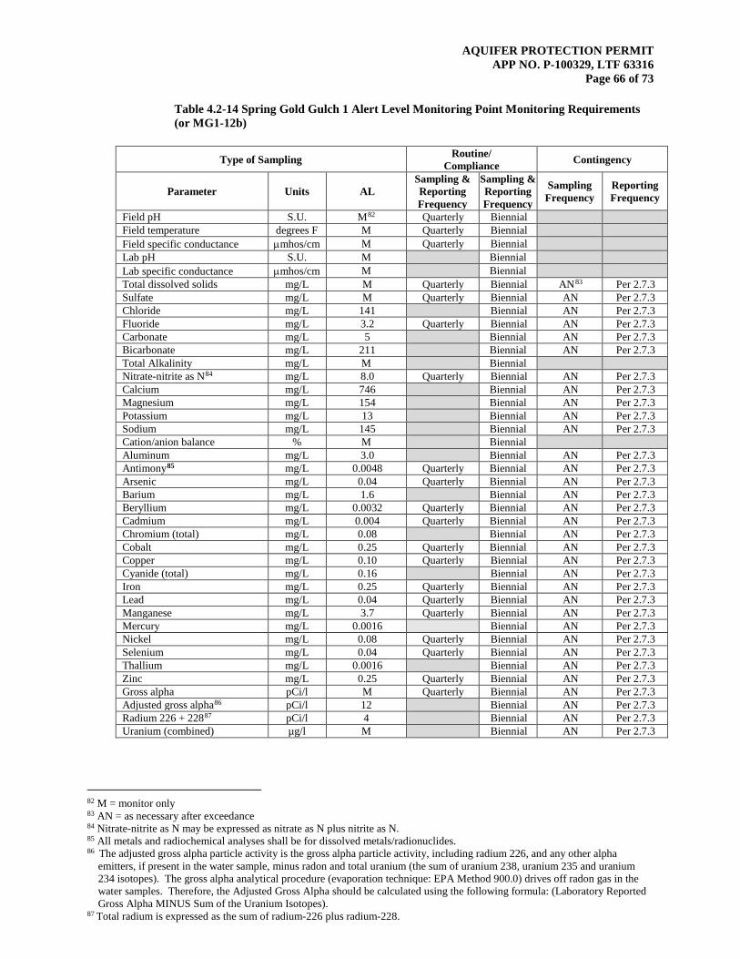
AQUIFER PROTECTION PERMIT APP NO. P-100329, LTF 63316
Page 66 of 73
Table 4.2-14 Spring Gold Gulch 1 Alert Level Monitoring Point Monitoring Requirements (or MG1-12b)
Type of Sampling Routine/ Compliance Contingency
Parameter Units AL Sampling & Reporting Frequency
Sampling & Reporting Frequency
Sampling Frequency
Reporting Frequency
Field pH S.U. M82 Quarterly Biennial Field temperature degrees F M Quarterly Biennial Field specific conductance µmhos/cm M Quarterly Biennial Lab pH S.U. M Biennial Lab specific conductance µmhos/cm M Biennial Total dissolved solids mg/L M Quarterly Biennial AN83 Per 2.7.3 Sulfate mg/L M Quarterly Biennial AN Per 2.7.3 Chloride mg/L 141 Biennial AN Per 2.7.3 Fluoride mg/L 3.2 Quarterly Biennial AN Per 2.7.3 Carbonate mg/L 5 Biennial AN Per 2.7.3 Bicarbonate mg/L 211 Biennial AN Per 2.7.3 Total Alkalinity mg/L M Biennial Nitrate-nitrite as N84 mg/L 8.0 Quarterly Biennial AN Per 2.7.3 Calcium mg/L 746 Biennial AN Per 2.7.3 Magnesium mg/L 154 Biennial AN Per 2.7.3 Potassium mg/L 13 Biennial AN Per 2.7.3 Sodium mg/L 145 Biennial AN Per 2.7.3 Cation/anion balance % M Biennial Aluminum mg/L 3.0 Biennial AN Per 2.7.3 Antimony85 mg/L 0.0048 Quarterly Biennial AN Per 2.7.3 Arsenic mg/L 0.04 Quarterly Biennial AN Per 2.7.3 Barium mg/L 1.6 Biennial AN Per 2.7.3 Beryllium mg/L 0.0032 Quarterly Biennial AN Per 2.7.3 Cadmium mg/L 0.004 Quarterly Biennial AN Per 2.7.3 Chromium (total) mg/L 0.08 Biennial AN Per 2.7.3 Cobalt mg/L 0.25 Quarterly Biennial AN Per 2.7.3 Copper mg/L 0.10 Quarterly Biennial AN Per 2.7.3 Cyanide (total) mg/L 0.16 Biennial AN Per 2.7.3 Iron mg/L 0.25 Quarterly Biennial AN Per 2.7.3 Lead mg/L 0.04 Quarterly Biennial AN Per 2.7.3 Manganese mg/L 3.7 Quarterly Biennial AN Per 2.7.3 Mercury mg/L 0.0016 Biennial AN Per 2.7.3 Nickel mg/L 0.08 Quarterly Biennial AN Per 2.7.3 Selenium mg/L 0.04 Quarterly Biennial AN Per 2.7.3 Thallium mg/L 0.0016 Biennial AN Per 2.7.3 Zinc mg/L 0.25 Quarterly Biennial AN Per 2.7.3 Gross alpha pCi/l M Quarterly Biennial AN Per 2.7.3 Adjusted gross alpha86 pCi/l 12 Biennial AN Per 2.7.3 Radium 226 + 22887 pCi/l 4 Biennial AN Per 2.7.3 Uranium (combined) µg/l M Biennial AN Per 2.7.3
82 M = monitor only 83 AN = as necessary after exceedance 84 Nitrate-nitrite as N may be expressed as nitrate as N plus nitrite as N. 85 All metals and radiochemical analyses shall be for dissolved metals/radionuclides. 86 The adjusted gross alpha particle activity is the gross alpha particle activity, including radium 226, and any other alpha
emitters, if present in the water sample, minus radon and total uranium (the sum of uranium 238, uranium 235 and uranium 234 isotopes). The gross alpha analytical procedure (evaporation technique: EPA Method 900.0) drives off radon gas in the water samples. Therefore, the Adjusted Gross Alpha should be calculated using the following formula: (Laboratory Reported Gross Alpha MINUS Sum of the Uranium Isotopes).
87 Total radium is expressed as the sum of radium-226 plus radium-228.

AQUIFER PROTECTION PERMIT APP NO. P-100329, LTF 63316
Page 67 of 73
Table 4.2-15 Raffinate Pond Alert Level Seep Monitoring Point Monitoring Requirements (Seep MG1-7a)
Type of Sampling Routine/ Compliance Contingency
Parameter Units AL Sampling & Reporting Frequency
Sampling & Reporting Frequency
Sampling Frequency
Reporting Frequency
Field pH S.U. M88 Quarterly Biennial Field temperature degrees F M Quarterly Biennial Field specific conductance µmhos/cm M Quarterly Biennial Lab pH S.U. M Biennial Lab specific conductance µmhos/cm M Biennial Total dissolved solids mg/L M Quarterly Biennial AN89 Per 2.7.3 Sulfate mg/L M Quarterly Biennial AN Per 2.7.3 Chloride mg/L 87 Biennial AN Per 2.7.3 Fluoride mg/L 3.2 Quarterly Biennial AN Per 2.7.3 Carbonate mg/L 5 Biennial AN Per 2.7.3 Bicarbonate mg/L 739 Biennial AN Per 2.7.3 Total Alkalinity mg/L M Biennial Nitrate-nitrite as N90 mg/L 8.0 Quarterly Biennial AN Per 2.7.3 Calcium mg/L 792 Biennial AN Per 2.7.3 Magnesium mg/L 168 Biennial AN Per 2.7.3 Potassium mg/L 17 Biennial AN Per 2.7.3 Sodium mg/L 140 Biennial AN Per 2.7.3 Cation/anion balance % M Biennial Aluminum mg/L 3.0 Biennial AN Per 2.7.3 Antimony91 mg/L 0.0048 Quarterly Biennial AN Per 2.7.3 Arsenic mg/L 0.04 Quarterly Biennial AN Per 2.7.3 Barium mg/L 1.6 Biennial AN Per 2.7.3 Beryllium mg/L 0.0032 Quarterly Biennial AN Per 2.7.3 Cadmium mg/L 0.004 Quarterly Biennial AN Per 2.7.3 Chromium (total) mg/L 0.08 Biennial AN Per 2.7.3 Cobalt mg/L 0.25 Quarterly Biennial AN Per 2.7.3 Copper mg/L 0.10 Quarterly Biennial AN Per 2.7.3 Cyanide (total) mg/L 0.16 Biennial AN Per 2.7.3 Iron mg/L 0.43 Quarterly Biennial AN Per 2.7.3 Lead mg/L 0.04 Quarterly Biennial AN Per 2.7.3 Manganese mg/L 1.8 Quarterly Biennial AN Per 2.7.3 Mercury mg/L 0.0016 Biennial AN Per 2.7.3 Nickel mg/L 0.08 Quarterly Biennial AN Per 2.7.3 Selenium mg/L 0.04 Quarterly Biennial AN Per 2.7.3 Thallium mg/L 0.0016 Biennial AN Per 2.7.3 Zinc mg/L 0.25 Quarterly Biennial AN Per 2.7.3 Gross alpha pCi/l M Quarterly Biennial AN Per 2.7.3 Adjusted gross alpha92 pCi/l 12 Biennial AN Per 2.7.3 Radium 226 + 22893 pCi/l 4 Biennial AN Per 2.7.3 Uranium (combined) µg/l M Biennial AN Per 2.7.3
88 M = monitor only 89 AN = as necessary after exceedance 90 Nitrate-nitrite as N may be expressed as nitrate as N plus nitrite as N. 91All metals and radiochemical analyses shall be for dissolved metals/radionuclides. 92 The adjusted gross alpha particle activity is the gross alpha particle activity, including radium 226, and any other alpha
emitters, if present in the water sample, minus radon and total uranium (the sum of uranium 238, uranium 235 and uranium 234 isotopes). The gross alpha analytical procedure (evaporation technique: EPA Method 900.0) drives off radon gas in the water samples. Therefore, the Adjusted Gross Alpha should be calculated using the following formula: (Laboratory Reported Gross Alpha MINUS Sum of the Uranium Isotopes).
93 Total radium is expressed as the sum of radium-226 plus radium-228.
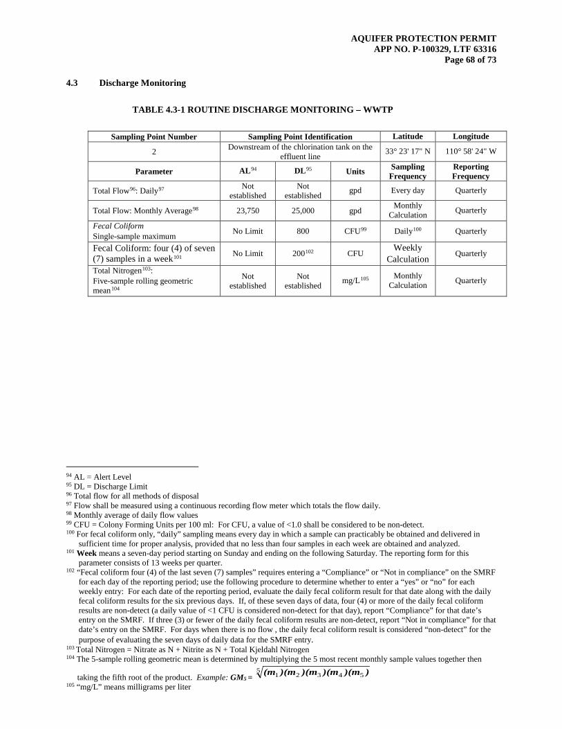
AQUIFER PROTECTION PERMIT APP NO. P-100329, LTF 63316
Page 68 of 73
4.3 Discharge Monitoring TABLE 4.3-1 ROUTINE DISCHARGE MONITORING – WWTP
Sampling Point Number Sampling Point Identification Latitude Longitude
2 Downstream of the chlorination tank on the effluent line 33° 23' 17" N 110° 58' 24" W
Parameter AL94 DL95 Units Sampling Frequency
Reporting Frequency
Total Flow96: Daily97 Not established
Not established gpd Every day Quarterly
Total Flow: Monthly Average98 23,750 25,000 gpd Monthly Calculation Quarterly
Fecal Coliform Single-sample maximum No Limit 800 CFU99 Daily100 Quarterly
Fecal Coliform: four (4) of seven (7) samples in a week101 No Limit 200102 CFU
Weekly Calculation
Quarterly
Total Nitrogen103: Five-sample rolling geometric mean104
Not established
Not established mg/L105 Monthly
Calculation Quarterly
94 AL = Alert Level 95 DL = Discharge Limit 96 Total flow for all methods of disposal 97 Flow shall be measured using a continuous recording flow meter which totals the flow daily. 98 Monthly average of daily flow values 99 CFU = Colony Forming Units per 100 ml: For CFU, a value of <1.0 shall be considered to be non-detect. 100 For fecal coliform only, “daily” sampling means every day in which a sample can practicably be obtained and delivered in
sufficient time for proper analysis, provided that no less than four samples in each week are obtained and analyzed. 101 Week means a seven-day period starting on Sunday and ending on the following Saturday. The reporting form for this
parameter consists of 13 weeks per quarter. 102 “Fecal coliform four (4) of the last seven (7) samples” requires entering a “Compliance” or “Not in compliance” on the SMRF
for each day of the reporting period; use the following procedure to determine whether to enter a “yes” or “no” for each weekly entry: For each date of the reporting period, evaluate the daily fecal coliform result for that date along with the daily fecal coliform results for the six previous days. If, of these seven days of data, four (4) or more of the daily fecal coliform results are non-detect (a daily value of <1 CFU is considered non-detect for that day), report “Compliance” for that date’s entry on the SMRF. If three (3) or fewer of the daily fecal coliform results are non-detect, report “Not in compliance” for that date’s entry on the SMRF. For days when there is no flow , the daily fecal coliform result is considered “non-detect” for the purpose of evaluating the seven days of daily data for the SMRF entry.
103 Total Nitrogen = Nitrate as N + Nitrite as N + Total Kjeldahl Nitrogen 104 The 5-sample rolling geometric mean is determined by multiplying the 5 most recent monthly sample values together then
taking the fifth root of the product. Example: GM5 = 5
54321 ))(m)(m)(m)(m(m 105 “mg/L” means milligrams per liter
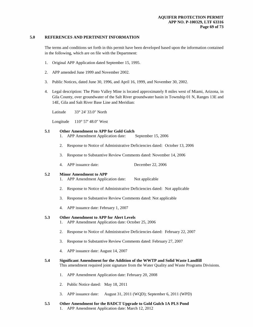
AQUIFER PROTECTION PERMIT APP NO. P-100329, LTF 63316
Page 69 of 73
5.0 REFERENCES AND PERTINENT INFORMATION
The terms and conditions set forth in this permit have been developed based upon the information contained in the following, which are on file with the Department:
1. Original APP Application dated September 15, 1995.
2. APP amended June 1999 and November 2002.
3. Public Notices, dated June 30, 1996, and April 16, 1999, and November 30, 2002.
4. Legal description: The Pinto Valley Mine is located approximately 8 miles west of Miami, Arizona, in Gila County, over groundwater of the Salt River groundwater basin in Township 01 N, Ranges 13E and 14E, Gila and Salt River Base Line and Meridian:
Latitude 33° 24' 33.0" North
Longitude 110° 57' 48.0" West
5.1 Other Amendment to APP for Gold Gulch 1. APP Amendment Application date: September 15, 2006
2. Response to Notice of Administrative Deficiencies dated: October 13, 2006
3. Response to Substantive Review Comments dated: November 14, 2006
4. APP issuance date: December 22, 2006
5.2 Minor Amendment to APP 1. APP Amendment Application date: Not applicable
2. Response to Notice of Administrative Deficiencies dated: Not applicable
3. Response to Substantive Review Comments dated: Not applicable
4. APP issuance date: February 1, 2007
5.3 Other Amendment to APP for Alert Levels 1. APP Amendment Application date: October 25, 2006
2. Response to Notice of Administrative Deficiencies dated: February 22, 2007
3. Response to Substantive Review Comments dated: February 27, 2007
4. APP issuance date: August 14, 2007
5.4 Significant Amendment for the Addition of the WWTP and Solid Waste Landfill This amendment required joint signature from the Water Quality and Waste Programs Divisions.
1. APP Amendment Application date: February 20, 2008
2. Public Notice dated: May 18, 2011
3. APP issuance date: August 31, 2011 (WQD); September 6, 2011 (WPD)
5.5 Other Amendment for the BADCT Upgrade to Gold Gulch 1A PLS Pond 1. APP Amendment Application date: March 12, 2012
AQUIFER PROTECTION PERMIT APP NO. P-100329, LTF 63316
Page 70 of 73
5.6 Significant Amendment for the Closure of TSF1
1. APP Amendment Application date: August 14, 2012
2. Public Notice dated: August 28, 2013
3. APP issuance date: September 30, 2013
5.7 Other Amendment to Transfer Ownership to Pinto Valley Mining Corp.
1. APP Amendment Application date: October 1, 2013
2. APP issuance date: October 8, 2013 (WPD), October 11, 2013 (WQD)
5.8 Other Amendment to APP to change Financial Assurance Mechanism
1. APP Amendment Application date: May 9, 2014
2. APP issuance date: June 23, 2014 (WQD), June 24, 2014 (WPD)
5.9 Significant Amendment to APP APP for the Addition of CDMD, NBMD, GGED, GGWD, Expansion of the LGLP, and removal of the East Dump
1. APP Amendment Application date: November 7, 2014
2. Public Notice dated: July 22, 2015
3. APP issuance date: October 9, 2015 (WQD), October 19, 2015 (WPD)
5.10 Significant Amendment to APP to Consolidate GGED, GGWD and the Expansion of the LGLP to form the Main Dump, and Removal of the North Dump
1. APP Amendment Application dated: December 1, 2015
2. Public Notice dated:

AQUIFER PROTECTION PERMIT APP NO. P-100329, LTF 63316
Page 71 of 73
6.0 NOTIFICATION PROVISIONS
6.1 Annual Registration Fees The permittee is notified of the obligation to pay an Annual Registration Fee to ADEQ. The Annual Registration Fee is based upon the amount of daily influent or discharge of pollutants in gallons per day as established by A.R.S. § 49-242.
6.2 Duty to Comply [A.R.S. §§ 49-221 through 49-263] The permittee is notified of the obligation to comply with all conditions of this permit and all applicable provisions of Title 49, Chapter 2, Articles 1, 2 and 3 of the Arizona Revised Statutes, Title 18, Chapter 9, Articles 1 through 4, and Title 18, Chapter 11, Article 4 of the Arizona Administrative Code. Any permit non-compliance constitutes a violation and is grounds for an enforcement action pursuant to Title 49, Chapter 2, Article 4 or permit amendment, suspension, or revocation.
6.3 Duty to Provide Information [A.R.S. §§ 49-243(K)(2) and 49-243(K)(8)] The permittee shall furnish to the Director, or an authorized representative, within a time specified, any information which the Director may request to determine whether cause exists for amending or terminating this permit, or to determine compliance with this permit. The permittee shall also furnish to the Director, upon request, copies of records required to be kept by this permit.
6.4 Compliance with Aquifer Water Quality Standards [A.R.S. §§ 49-243(B)(2) and 49-243(B)(3)] The permittee shall not cause or contribute to a violation of an aquifer water quality standard at the applicable point of compliance for the facility. Where, at the time of issuance of the permit, an aquifer already exceeds an aquifer water quality standard for a pollutant, the permittee shall not discharge that pollutant so as to further degrade, at the applicable point of compliance for the facility, the water quality of any aquifer for that pollutant.
6.5 Technical and Financial Capability [A.R.S. §§ 49-243(K)(8) and 49-243(N) and A.A.C. R18-9-A202(B) and R18-9-A203(E) and (F)] The permittee shall have and maintain the technical and financial capability necessary to fully carry out the terms and conditions of this permit. Any bond, insurance policy, trust fund, or other financial assurance mechanism provided as a demonstration of financial capability in the permit application, pursuant to A.A.C. R18-9-A203(D), shall be in effect prior to any discharge authorized by this permit and shall remain in effect for the duration of the permit.
6.6 Reporting of Bankruptcy or Environmental Enforcement [A.A.C. R18-9-A207(C)] The permittee shall notify the Director within five days after the occurrence of any one of the following:
1. The filing of bankruptcy by the permittee.
2. The entry of any order or judgment not issued by the Director against the permittee for the enforcement of any environmental protection statute or rule.
6.7 Monitoring and Records [A.R.S. § 49-243(K)(8) and A.A.C. R18-9-A206] The permittee shall conduct any monitoring activity necessary to assure compliance with this permit, with the applicable water quality standards established pursuant to A.R.S. §§ 49 221 and 49 223 and §§ 49 241 through 49 252.
AQUIFER PROTECTION PERMIT APP NO. P-100329, LTF 63316
Page 72 of 73
6.8 Inspection and Entry [A.R.S. §§ 41-1009, 49-203(B) and 49-243(K)(8)] In accordance with A.R.S. §§ 41-1009 and 49-203(B), the permittee shall allow the Director, or an authorized representative, upon the presentation of credentials and other documents as may be required by law, to enter and inspect the facility as reasonably necessary to ensure compliance with Title 49, Chapter 2, Article 3 of the Arizona Revised Statutes, and Title 18, Chapter 9, Articles 1 through 4 of the Arizona Administrative Code and the terms and conditions of this permit.
6.9 Duty to Modify [A.R.S. § 49-243(K)(8) and A.A.C. R18-9-A211] The permittee shall apply for and receive a written amendment before deviating from any of the designs or operational practices specified by this permit.
6.10 Permit Action: Amendment, Transfer, Suspension & Revocation [A.R.S. §§ 49-201, 49-241 through 251, A.A.C. R18-9-A211, R18-9-A212 and R18-9-A213] This permit may be amended, transferred, renewed, or revoked for cause, under the rules of the Department.
The permittee shall notify the Water Permits Section in writing within 15 days after any change in the owner or operator of the facility. The notification shall state the permit number, the name of the facility, the date of property transfer, and the name, address, and phone number where the new owner or operator can be reached. The operator shall advise the new owner or operators of the terms of this permit and the need for permit transfer in accordance with the rules.

AQUIFER PROTECTION PERMIT APP NO. P-100329, LTF 63316
Page 73 of 73
7.0 ADDITIONAL PERMIT CONDITIONS
7.1 Other Information [A.R.S. § 49-243(K)(8)] Where the permittee becomes aware that it failed to submit any relevant facts in a permit application, or submitted incorrect information in a permit application or in any report to the Director, the permittee shall promptly submit the correct facts or information.
7.2 Severability [A.R.S. §§ 49-201, 49-241 through 251, A.A.C. R18-9-A211, R18-9-A212 and R18-9-A213] The provisions of this permit are severable, and if any provision of this permit, or the application of any provision of this permit to any circumstance, is held invalid, the application of such provision to other circumstances, and the remainder of this permit, shall not be affected thereby. The filing of a request by the permittee for a permit action does not stay or suspend the effectiveness of any existing permit condition.
7.3 Permit Transfer This permit may not be transferred to any other person except after notice to and approval of the transfer by the Department. No transfer shall be approved until the applicant complies with all transfer requirements as specified in A.A.C. R18-9-A212(B) and (C).