draft baseline and monitoring methodology am00xx “prevention of sf6...
TRANSCRIPT

CDM – Meth Panel Thirty-seventh meeting Report Annex 1 Sectoral scope: 11
1/30
Draft baseline and monitoring methodology AM00XX
“Prevention of SF6 venting following tests of Gas insulated electrical equipment”
I. SOURCE, DEFINITIONS AND APPLICABILITY
Sources
This baseline and monitoring methodology is based on the following proposed new methodology:
• NM0251 “Prevention of SF6 venting following tests of Gas insulated electrical equipment”, prepared by EcoSecurities.
This methodology refers to the latest approved versions of the following tools:
• Tool to calculate project or leakage CO2 emissions from fossil fuel combustion; • Tool to calculate baseline, project and/or leakage emissions from electricity consumption; • Combined tool to identify the baseline scenario and demonstrate additionality.
For more information regarding the proposed new methodologies and the tools as well as their consideration by the Executive Board please refer to <http://cdm.unfccc.int/goto/MPappmeth>.
Selected approach from paragraph 48 of the CDM modalities and procedures
“Existing actual or historical emissions, as applicable”.
Definitions
For the purpose of this methodology, the following definitions apply:
Recovery. Recovery means the collection and storage of fluorinated greenhouse gases from, for example, machinery, equipment and containers.1 Reclamation. Reclamation means the reprocessing of a recovered fluorinated greenhouse gas in order to meet a specified standard of performance.2 Test. A series of operations used to determine if an apparatus (e.g. a circuit breaker) complies with certain standards for operating performance. Tests are performed as part of a certification process or as part of development stage testing. Testing Item. Each separate operation that together compose the series of operations making up a test.
1 REGULATION (EC) No 842/2006 OF THE EUROPEAN PARLIAMENT AND OF THE COUNCIL of 17 May 2006 on certain fluorinated greenhouse gases. 2 REGULATION (EC) No 842/2006 OF THE EUROPEAN PARLIAMENT AND OF THE COUNCIL of 17 May 2006 on certain fluorinated greenhouse gases.

CDM – Meth Panel Thirty-seventh meeting Report Annex 1 Sectoral scope: 11
2/30
Electrical Test. A test that examines the electrical functionality of a gas insulated electrical equipment (GIEE) and requires the equipment to be filled with SF6 gas; restricted to any test involving short-circuit, capacitive current switching, load current switching, inductive current switching or switching operations.
Applicability
This methodology applies to projects where SF6 emissions are reduced by implementing recovery of used SF6 gas that would be vented after the testing of gas insulated electrical equipment (GIEE) at a testing facility, called the SF6 recovery site. This methodology applies when the recovered gas is then reclaimed at an SF6 production facility, called the SF6 reclamation site. This methodology applies to projects that involve installation of recovery systems at the SF6 recovery site and transport of used SF6 to an existing SF6 production facility for the purpose of its reclamation.
The methodology is applicable under the following conditions:
• The SF6 recovery site uses SF6 in the testing of gas insulated electrical equipment (GIEE) (e.g. circuit breaker, switchgear). Such tests are performed as part of a certification or rating process, or during development or production of new electrical equipment;
• The testing considered for the project is Electrical Tests of medium and high voltage rated equipment ( >1 kV);
• Before the project, SF6 gas used in the equipment for tests is vented following testing. • There is no option to reuse the vented SF6 in the SF6 recovery site; • The recovered gas is reclaimed by using it as a feedstock in the production of new SF6 on the
premises of an existing SF6 production facility; • Reclaimed SF6 is a minor component of the total SF6 production of the SF6 reclamation site (less
than 5% of total production); • Issuance requests shall be formulated for periods equal to one or several years as the procedures to
remove the possibility of gaming are designed on a yearly basis; • The testing is performed at the request of a client according to a national or international standard,
and the facility operator has no discretion in the type or frequency of tests.
In addition, the applicability conditions included in the tools referred to above apply.
Finally, this methodology is only applicable if the application of the procedure to identify the baseline scenario results in a baseline involving the venting of SF6 as the most plausible scenario for the SF6 recovery site.
II. BASELINE METHODOLOGY PROCEDURE
Identification of the baseline scenario
Project proponents shall apply the following steps to identify the baseline scenario:
Use the “Combined tool to identify the baseline scenario and demonstrate additionality”, taking into account the specifications below, to determine the most plausible baseline scenario for management of used SF6 gas at the SF6 recovery site and to demonstrate the additionality of the project activity.
CDM – Meth Panel Thirty-seventh meeting Report Annex 1 Sectoral scope: 11
3/30
Baseline Alternatives
The baseline must be determined for the management of used SF6 gas at the SF6 recovery site.
Consider at least the following alternatives for managing used SF6 gas at the SF6 recovery site:
(a) Continuation of current practice, which shall be described in the CDM PDD. (b) Capture and incineration of used SF6. (c) Capture and reclamation of used SF6 at the chosen SF6 reclamation site (the project activity
without CDM). (d) Capture and transport of used SF6 to other facilities for reclamation.
Consistency with mandatory applicable laws and regulations
During baseline alternative selection, eliminate any options that do not comply with existing laws and regulations.
Additionality
Additionality will be demonstrated using the latest version of the “Combined tool to identify the baseline scenario and demonstrate additionality”. The demonstration of additionality must take into account the entire activity within the project boundary, including the recovery, transport, and reclamation facilities.
If the investment analysis of the combined tool is applied, it should consider the costs and benefits of the baseline alternatives for used SF6 gas. For example following costs can be included for CDM project activity at both the sites; SF6 recovery site and SF6 reclamation site.
• Cost to install SF6 recovery system; • Increased O&M costs at reclamation site; • Savings on raw materials to produce SF6 at reclamation site (including raw materials such as
anhydrous hydrogen fluoride (AHF) and molten sulphur); • The transportation costs.
Project boundary
The spatial extent of the project boundary encompasses:
The SF6 recovery site
• The locations where test equipment is filled with SF6, where this equipment is tested, and where the gas is vented (in the baseline scenario) and recovered (in the project scenario);
• All equipment for recovery of used SF6; • The dedicated recovery cylinders in which used SF6 is stored.
The SF6 reclamation site
• The dedicated recovery cylinders in which used SF6 is stored; • The laboratory where recovered gas is tested for SF6 content;
CDM – Meth Panel Thirty-seventh meeting Report Annex 1 Sectoral scope: 11
4/30
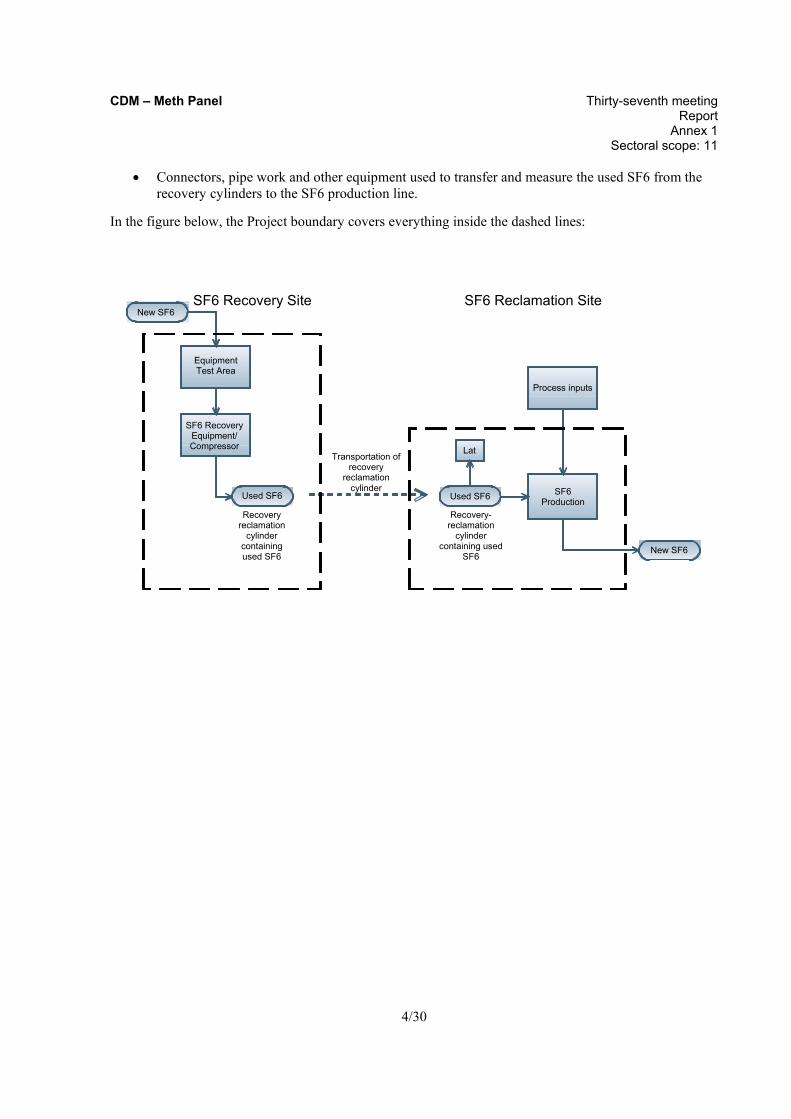
• Connectors, pipe work and other equipment used to transfer and measure the used SF6 from the recovery cylinders to the SF6 production line.
In the figure below, the Project boundary covers everything inside the dashed lines:
Equipment Test Area
SF6 Production
Process inputs
New SF6
New SF6
Used SF6
SF6 Recovery Site SF6 Reclamation Site
Lat
Used SF6
SF6 Recovery Equipment/ Compressor
Recovery-reclamation
cylinder containing used
SF6
Transportation of recovery
reclamation cylinder
Recovery reclamation
cylinder containing used SF6
CDM – Meth Panel Thirty-seventh meeting Report Annex 1 Sectoral scope: 11
5/30
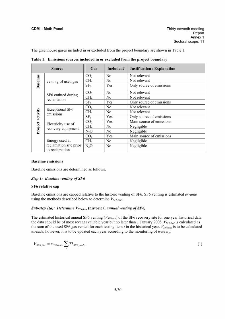
The greenhouse gases included in or excluded from the project boundary are shown in Table 1.
Table 1: Emissions sources included in or excluded from the project boundary
Source Gas Included? Justification / Explanation
CO2 No Not relevant CH4 No Not relevant
Bas
elin
e
venting of used gas SF6 Yes Only source of emissions
CO2 No Not relevant CH4 No Not relevant SF6 emitted during
reclamation SF6 Yes Only source of emissions CO2 No Not relevant CH4 No Not relevant Exceptional SF6
emissions SF6 Yes Only source of emissions CO2 Yes Main source of emissions CH4 No Negligible Electricity use of
recovery equipment N2O No Negligible CO2 Yes Main source of emissions CH4 No Negligible
Proj
ect a
ctiv
ity
Energy used at reclamation site prior to reclamation
N2O No Negligible
Baseline emissions
Baseline emissions are determined as follows.
Step 1: Baseline venting of SF6
SF6 relative cap
Baseline emissions are capped relative to the historic venting of SF6. SF6 venting is estimated ex-ante using the methods described below to determine VSF6,hist..
Sub-step 1(a): Determine VSF6,hist (historical annual venting of SF6) The estimated historical annual SF6 venting (VSF6,hist) of the SF6 recovery site for one year historical data, the data should be of most recent available year but no later than 1 January 2008. VSF6,hist is calculated as the sum of the used SF6 gas vented for each testing item t in the historical year. VSF6,hist is to be calculated ex-ante; however, it is to be updated each year according to the monitoring of wSF6,BL,y.
∑=t
tusedSFhistSFhistSF TIwV ,,6,6,6
(1)

CDM – Meth Panel Thirty-seventh meeting Report Annex 1 Sectoral scope: 11
6/30
Where: VSF6,hist = Historical annual venting of SF6, in tonnes SF6 TISF6,used,t = Used gas vented during eligible testing item t, tonnes gas (see Sub-step 1(b)) wSF6,hist = Concentration of SF6 expected in used gas in the historical period, tonnes
SF6/tonnes gas
Sub-step 1(b): Determine TISF6,used,t (Used gas vented during eligible testing items t)
Testing of equipment may be comprised of one or several testing items performed on different subparts of a single equipment. Records, in the form of direct measurements or other indirect data to estimate SF6 emissions are required for each testing item to be included in the historical baseline determined ex-ante. Two different methods are described in this section to determine or estimate the used SF6 gas vented, TISF6,used,t, for each testing item t.
Method 1. Records of gas use (preferred)
If the SF6 recovery site has historical records of SF6 gas vented for the testing instance t in the form of measurements of SF6 filled into the equipment prior to or used gas removed after the test that complies with the monitoring requirements stated in section “Data and Parameters not Monitored”, then TISF6,used,t is to be taken from the monitored data.
Method 2. Reconstruction based on Manufacturer Specification/ Nameplate or estimated equipment capacity
If the SF6 recovery site does not have monitored data of used gas vented for testing item t, then TISF6,BL,t shall be reconstructed using the procedure described in Annex A. Note that, for the purpose of conducting Step 3 below, the procedure described in Annex A needs to be conducted even when the record of gas use is available.
Step 2: Annual SF6 reclamation during the project activity
Next, amount of SF6 reclaimed as a result of the project activity shall be monitored annually. For this purpose, monitored data from project year y to determine SF6 reclaimed in that year shall be used. Given the nature of the project activity, the unit used as a basis for calculation is the recovery-reclamation cylinder i. Note that recovery-reclamation cylinder i refers to each cycle that a cylinder goes through (i.e. from the moment the cylinder is taken to the recovery site until the moment the gas contained in the cylinder has been injected into the reclamation facility) and not the physical cylinder.3
Only those cylinders that complete the recovery-reclamation process in year y can be included in the calculation of emissions avoided in year y. If a recovery cylinder has not completed the recovery-reclamation process in the crediting year y, then it must be included in the year y+1, as illustrated below.
3 In some cases the same physical cylinder may be used for more than one recovery-reclamation cycle in the
crediting period y. However, if a cylinder is reused, it will have to be clearly labelled in each recovery-reclamation cycle.

CDM – Meth Panel Thirty-seventh meeting Report Annex 1 Sectoral scope: 11
7/30
i i+1 … n-1 n
y y + 1
i i+1 …
y y + 1
n-1 n
The emissions avoided in year y from each cylinder i, CAi,y is determined ex-post based on the minimum among the following:
Where: MRGas,i,y = Mass of used gas recovered into cylinder i at the SF6 recovery site in year y MS Gas, i,y = Mass of used gas stored in recovery cylinder i in year y, tonnes gas MIGas, i,y = Mass of used gas from cylinder i which is injected for reclamation process in year y,
tonnes gas i = Sub-index used for each cylinder that completed a recovery-reclamation cycle
included in the estimation of emissions avoided for the year y
Take the minimum of the three to determine the cylinder minimum for each cylinder i:
{ }yiGasyiGasyiGasyi MIMSMRMINCA ,,,,,,, ,,=
(2)
Where: CAi,y = Cylinder minimum for cylinder i in year y, tonnes gas
Determine the quantity of SF6 reclaimed during the year y:
∑ ∗=i
iSFyiy wCAEA ,6,
(3)
Where: EAy = Quantity of SF6 reclaimed during the year y, tonnes SF6 wSF6,i = Concentration of SF6 in the cylinder i, tonnes SF6/tonnes gas
Step 3: Establish the discount factor for number of testing
Thirdly, the cylinder minimum obtained as per Step 2 shall be discounted for any possible increase in the number of testing per equipment compared with the historic baseline period. In order to address this, the following steps shall be taken.

CDM – Meth Panel Thirty-seventh meeting Report Annex 1 Sectoral scope: 11
8/30
Sub-step 3(a) Define the maximum number of equal range, in KV, categories that contain at least 5 equipments both of the historic and project samples. For example, if the number of categories is 5, and the equipments ranging from 50kV to 500kV are tested in the historic baseline period and the equipments ranging from 100kV to 800kV are tested in the project year, then the range shall be set at 50kV to 800kV, and the categories should be: 50 to 200kV, 201 to 350kV, 351 to 500kV, 501 to 650kV, and 651 to 800kV. If less than 5 equipments are tested either in the historic or project period, then there shall be one category. Sub-step 3(b) Derive the average number of eligible testing items where venting occurred per equipment in category k in the baseline (NTBL,k), by using the database compiled when determining TISF6,used,t. Sub-step 3(c) Derive the average number of total testing items where recovery was done per equipment in the project in category k in the year y, (NTPJ,k,y) by using the testing records from the project year.
Sub-step 3(d)
Calculate the ratio of number of eligible testing items for each category k as follows:
ykPJ
kBLyk NT
NTRT
,,
,, = (4)
Where: RTk,y = Ratio of number of eligible testing items in category k (maximum value is set at 1) NTBL,k = Average number of eligible testing items where venting occurred per equipment in
the baseline, for category k NTPJ,k,y = Average number of total testing items where recovery was done per equipment in
the project, for category k
Obtain discount factor for testing, DFTy:
( )ySF
kykykSF
y Q
RTQDFT
,6
,,,6 *∑= (5)
∑=j
yjkSFykSF QQ ,,,6,,6 (5.1)
∑=k
ykSFySF QQ ,,6,6 (5.2)

CDM – Meth Panel Thirty-seventh meeting Report Annex 1 Sectoral scope: 11
9/30
Where: DFTy = Discount factor for testing in year y QSF6,k,y = Total amount of SF6 filled in the testing of equipments in category k in year y,
tonnes SF6 QSF6,y = Total amount of SF6 filled in testing of all equipments in the project activity in year
y, tonnes SF6 RTk,y = Ratio of number of eligible testing items in category k (maximum value is set at 1) QSF6,k,j,y = Amount of SF6 that is filled into equipment j of category k in year y at the SF6
recovery site, tonnes SF6
Step 4: Calculate the baseline emissions
Calculate baseline emissions as the minimum between the quantity of SF6 reclaimed during the year, discounted for number of testing, and the best estimate of historical annual emissions VSF6,hist, determined in Step 1.
{ } 6,6 *, SFyyhistSFy GWPEADFTVMINBE ∗=
(6)
Where: BEy = Baseline emissions year y, tCO2e DFTy = Discount factor for testing in year y EAy = Quantity of SF6 reclaimed during the year y, tonnes SF6 VSF6,hist = Historical annual baseline venting of SF6, tonnes SF6 GWPSF6 = Global warming potential of SF6, tCO2e / tonnes SF6
Project emissions
Project emissions include used SF6 emitted during reclamation and any exceptional emissions at the SF6 reclamation site.
Step 1: Used SF6 emitted during reclamation
Project proponents shall identify every point in the production of SF6 at the SF6 reclamation site, after the point of injection of used SF6, where SF6 gas is emitted (for example, a purge gas outlet). During the project year y, a mass balance of inputs and products should be carried out (this should take into account inter alia: anhydrous hydrogen fluoride (AHF), molten sulfur, recycled SF6 and finished products), and any discrepancy shall be proportionately allocated in the following manner.
( )
⋅−= ∑=
y
n
iySFhistyiPJSFyRCL BEPFEFEGWPMINPE ,.
1,6,,6, (7)
and
yiSFySFyiPJ QPFE ,,6,6,, /1−= (8)
histSFhistSFhist QPFE ,6,6 /1−= (9)

CDM – Meth Panel Thirty-seventh meeting Report Annex 1 Sectoral scope: 11
10/30
Where: PERCL,y = Project emissions from the emission of SF6 during reclamation in the year y, tCO2e GWPSF6 = Global warming potential of SF6, tCO2e / t SF6 FEPJ,i,y = SF6 emitted during reclamation of used SF6 as compared to total production during
the reclamation period of cylinder i in project year y, by comparing the discrepancy of the inputs and products
FEhist = SF6 emitted during production of SF6 in the baseline as compared to total production of SF6 during the baseline period, by comparing the discrepancy of the inputs and product
PSF6,y = Production of SF6 during the project year y, tonnes SF6 PSF6,hist = Production of SF6 during the historical period, tonnes SF6 QSF6,i,y = Theoretical production of SF6 during the reclamation period of cylinder i in project
year y, in tonnes SF6, as obtained by a stoichiometric calculation based on the consumption data of reclaimed SF6, AHF, molten sulphur and any other inputs
QSF6,hist = Theoretical production of SF6 during the historical period, tonnes SF6, as obtained by a stoichiometric calculation based on the consumption data of AHF and molten sulphur and any other inputs
i = Sub-index used for each cylinder that completed a recovery-reclamation cycle included in the estimation of emissions avoided for the year y
n = Number of cylinders that completed a recovery-reclamation cycle in the year y. Only these cylinders are eligible to be included in the estimation of emissions avoided for the year y
Step 2: Electricity use of recovery equipment
Emissions as a result of electricity consumption at the testing facility (PETF,y) and reclamation facility (PERF,y)due to the use of recovery equipment shall be taken into account, according to “Tool to calculate baseline, project and/or leakage emissions from electricity consumption”. Since emissions due to electricity consumption of these facilities are assumed to be small, electricity consumption can be approximated by the rated capacity of the operating equipment multiplied by operating hours of the facility.
Step 3: Exceptional Project Emissions
It is unlikely but not impossible that an exceptional event at the SF6 reclamation site, for example an accident or emergency plant shutdown, could lead to the emission of SF6 injected for reclamation.
The project proponent must record the date and time of any such exceptional event that occurs in year y that results in the exceptional emission of SF6. The SF6 quantity (EXCSF6,y) from any reclamation that coincides with the event must be considered as project emissions (PEEXC,y). For example, if a recovery cylinder of used gas was being reclaimed when the event occurred, then the amount of gas extracted from the cylinder between 5 hours prior to the exceptional event and the time that the injection line was closed must be considered as EXCSF6,y.
ySFSFyEXC EXCGWPPE ,66, ⋅= (10)

CDM – Meth Panel Thirty-seventh meeting Report Annex 1 Sectoral scope: 11
11/30
Where PEEXC,y = Project emissions from exceptional event(s) at the SF6 reclamation site in year y,
tCO2e GWPSF6 = Global warming potential of SF6, t CO2e / t SF6 EXCSF6,y = Quantity of SF6 which was being injected to the reclamation facility during
exceptional events occurred in year y, tonnes SF6
Step 4: Total Project Emissions
The project emissions in year y are the sum of the two potential sources.
yEXCyRFyTFyRCLy PEPEPEPEPE ,,,, +++= (11)
Where: PEy = Project emissions in year y, tCO2e PERCL,y = Project emissions from emission of SF6 during reclamation in year y, tCO2e PETF,y = Project emissions as a result of increased electricity consumption at the testing
facility attributable to project activity in year y, tCO2e (Refer the “data monitored” section)
PERF,y = Project emissions as a result of increased electricity consumption at the reclamation facility attributable to project activity in year y, tCO2e (Refer the “data monitored” section)
PEEXC,y = Project emissions from exceptional event(s) at the SF6 reclamation site in year y, tCO2e
Leakage
Leakage emissions attributable to the project activity could result from the following:
(a) Transportation of the cylinders from the SF6 recovery site to the SF6 reclamation site (LEtrans,y);
If ( )
%1.0, ≤− yy
estTrans
PEBELE
(12)
LETrans,est = Estimated annual emissions from transport of the cylinders from the SF6 recovery
site to the SF6 reclamation site, tCO2e (Refer the “data not monitored” section)
Then the leakage emissions associated with the Project are deemed to be negligible compared to the range of uncertainty of the GWP estimate, and they can be ignored during the crediting period (LEy = 0).
In the case that the estimated leakage emissions do not fulfil the above condition, use the following to calculate LEy each year:
yTransy LELE ,= (13)
CDM – Meth Panel Thirty-seventh meeting Report Annex 1 Sectoral scope: 11
12/30
Where: LEy = Leakage emissions in year y, tCO2e LETrans,y = Emissions from transport of the cylinders from the SF6 recovery site to the SF6
reclamation site in year y, tCO2e (Refer the “data monitored” section)
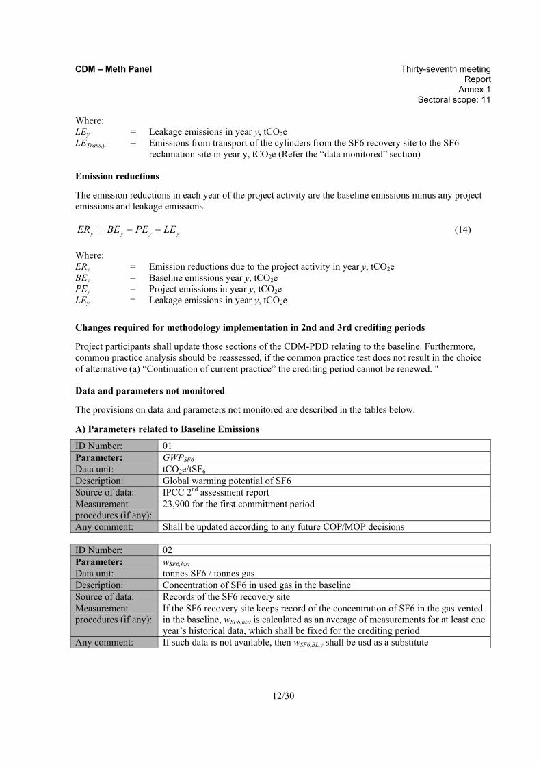
Emission reductions
The emission reductions in each year of the project activity are the baseline emissions minus any project emissions and leakage emissions.
yyyy LEPEBEER −−= (14)
Where: ERy = Emission reductions due to the project activity in year y, tCO2e BEy = Baseline emissions year y, tCO2e PEy = Project emissions in year y, tCO2e LEy = Leakage emissions in year y, tCO2e
Changes required for methodology implementation in 2nd and 3rd crediting periods
Project participants shall update those sections of the CDM-PDD relating to the baseline. Furthermore, common practice analysis should be reassessed, if the common practice test does not result in the choice of alternative (a) “Continuation of current practice” the crediting period cannot be renewed. "
Data and parameters not monitored
The provisions on data and parameters not monitored are described in the tables below.
A) Parameters related to Baseline Emissions
ID Number: 01 Parameter: GWPSF6 Data unit: tCO2e/tSF6 Description: Global warming potential of SF6 Source of data: IPCC 2nd assessment report Measurement procedures (if any):
23,900 for the first commitment period
Any comment: Shall be updated according to any future COP/MOP decisions ID Number: 02 Parameter: wSF6,hist Data unit: tonnes SF6 / tonnes gas Description: Concentration of SF6 in used gas in the baseline Source of data: Records of the SF6 recovery site Measurement procedures (if any):
If the SF6 recovery site keeps record of the concentration of SF6 in the gas vented in the baseline, wSF6,hist is calculated as an average of measurements for at least one year’s historical data, which shall be fixed for the crediting period
Any comment: If such data is not available, then wSF6,BL,y shall be usd as a substitute

CDM – Meth Panel Thirty-seventh meeting Report Annex 1 Sectoral scope: 11
13/30
ID Number: 03 Parameter: TISF6,used,t Data unit: tonnes gas Description: Used gas vented during eligible testing item t for the historical baseline year Source of data: records of the SF6 recovery site Measurement procedures (if any):
Method 1: Measurements of filling: Use the value resulting from measurement by a flow meter that was subject to calibration according to manufacturer recommendations or better. Provide the records described in Annex A Steps 1 and 4. Method 2: Follow procedures described in Annex A and provide all “CDM Records” as required by the procedure. Project proponents should clearly state which Method is used for each testing item t.All testing records of the baseline year(s) are to be made available to the validator, and a summary of these to the UNFCCC at request for registration; however, these are not published online due to business interests of the third party testing institute (the SF6 recovery site).Testing records should be available in electronic records and/or paper
Any comment: Uncertainty for Method 1 is low since it relies on actual measurements of SF6 gas quantities Uncertainty for Method 2: When using manufacturer specification/ nameplate as the source of SF6 capacity, manufacturer specifications imply the minimum gas required to meet equipment performance requirements. Consequently, the use of this method implies a low estimate. Therefore uncertainty of the SF6 quantity per equipment is low. When using estimated equipment capacities, an uncertainty explanation is to be included
ID Number: 04 Parameter: Decision flow chart for the destination of removed SF6 Data unit: dimensionless Description: A decision flow chart to determine instances where used gas was legitimately
vented in the past Source of data: Use the default provided here Measurement procedures (if any):
Apply the default Decision flow chart for the destination of removed SF6 provided in Annex A. The Decision flow chart should reflect or be more conservative than the current practice at the recovery site as documented in response to the Identification of the baseline scenario section
Any comment:

CDM – Meth Panel Thirty-seventh meeting Report Annex 1 Sectoral scope: 11
14/30
ID Number: 05 Parameter: k Data unit: dimensionless Description: Sub-index used for equipment categories Source of data: N/A Measurement procedures (if any):
Equipment is assigned to a category according to historical or project testing records of the equipment voltage rating
Any comment: See Step 3 of baseline emissions
ID Number: 06 Parameter: NTBL,k
Data unit: dimensionless Description: Average number of eligible testing items where venting occurred per equipment in
the baseline, for category k Source of data: records of the SF6 recovery site Measurement procedures (if any):
Use the database compiled when determining TISF6,used,t For each equipment in the database, assign the equipment to a category k. Count the number of eligible testing items where venting occurred for each equipment. For each category k, make an average of the counts for equipment in that category to derive NTBL,k.
Any comment: See Step 3 of baseline emissions
B) Parameters related to Project emissions
ID Number: 07 Parameter: PSF6,hist Data unit: tonnes SF6 Description: Production of SF6 during the historical period, tonnes SF6 Source of data: Records of the SF6 reclamation site Measurement procedures (if any):
Production or sales records
Any comment:
ID Number: 08 Parameter: QSF6,hist Data unit: tonnes SF6 Description: Theoretical production of SF6 during the reclamation period of cylinder i in
project year y, in tonnes SF6, as obtained by a stoichiometric calculation based on the consumption data of reclaimed SF6, AHF, molten sulphur and any other inputs
Source of data: Records of the SF6 reclamation site Measurement procedures (if any):
Purchase or production records of AHF and sulphur as well as records of production, taking into account inventory change
Any comment: Production of SF6 shall be estimated on the basis of AHF and sulphur used, and not consumed by any other products

CDM – Meth Panel Thirty-seventh meeting Report Annex 1 Sectoral scope: 11
15/30
C) Parameters related to Leakage
ID Number: 09 Parameter: LETrans,est
Data unit: tCO2e Description: Estimated annual emissions from transport of the cylinders from the SF6
recovery site to the SF6 reclamation site Source of data: project proponent Measurement procedures (if any):
Estimate based on the “Tool to calculate project or leakage CO2 emissions from fossil fuel combustion” or on the “Baseline emissions accounting method” of AMS-III.C. Emission reductions by low-greenhouse gas emitting vehicles
Any comment:
III. MONITORING METHODOLOGY
All data collected as part of monitoring should be archived electronically and be kept at least for 2 years after the end of the last crediting period. All measurements should be conducted with calibrated measurement equipment according to relevant industry standards.
In addition, the monitoring provisions in the tools referred to in this methodology apply.
The monitoring plan described in the PDD should address the following:
• Data collection; • Data archiving; • Responsibility for each component of the monitoring plan; • Ultimate responsibility for monitoring of the CDM project.
The following figure illustrates schematically the monitoring system for baseline and project emissions:

CDM – Meth Panel Thirty-seventh meeting Report Annex 1 Sectoral scope: 11
16/30
Project Monitoring Plan
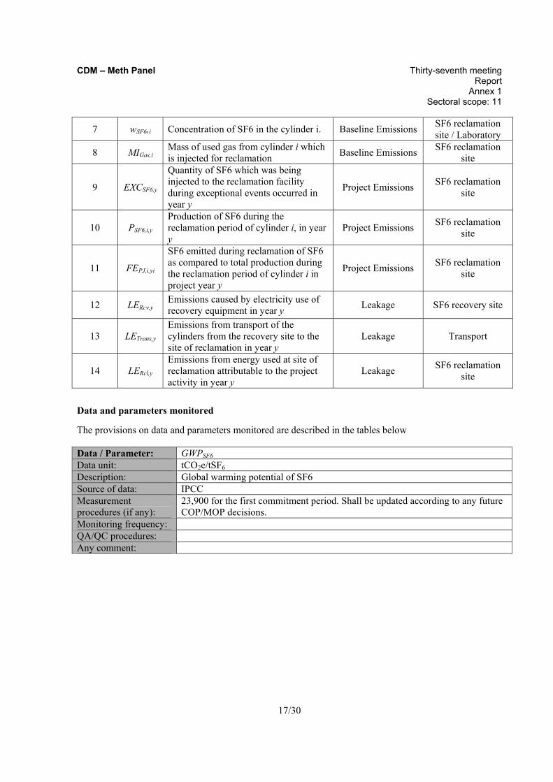
Number Code Description Purpose / Use Location
1 QSF6,k,j,y
Mass of SF6 that is filled into equipment j in year y at the SF6 recovery site
Baseline Emissions SF6 recovery site
2 NTPJ,k,y
Average number of total testing items where recovery was done per equipment in the project, for category k
Baseline Emissions SF6 recovery site
3 MRGas,i Mass of used gas that is recovered into cylinder i at the SF6 recovery site Baseline Emissions SF6 recovery site
4 i
Sub-index used for each cylinder that completed a recovery-reclamation cycle included in the estimation of emissions avoided for the year y
Baseline Emissions SF6 recovery site, SF6 reclamation
site
5 n
Number of cylinders that completed a recovery-reclamation cycle in the year y. Only these cylinders are eligible to be included in the estimation of emissions avoided for the year y
Baseline Emissions SF6 recovery site, SF6 reclamation
site
6 MSGas,i Mass of used gas stored in recovery cylinder i during the year y Baseline Emissions SF6 recovery site
CDM – Meth Panel Thirty-seventh meeting Report Annex 1 Sectoral scope: 11
17/30
7 wSF6,i Concentration of SF6 in the cylinder i. Baseline Emissions SF6 reclamation site / Laboratory
8 MIGas,i Mass of used gas from cylinder i which is injected for reclamation Baseline Emissions SF6 reclamation
site
9 EXCSF6,y
Quantity of SF6 which was being injected to the reclamation facility during exceptional events occurred in year y
Project Emissions SF6 reclamation site
10 PSF6,i,y Production of SF6 during the reclamation period of cylinder i, in year y
Project Emissions SF6 reclamation site
11 FEPJ,i,yi
SF6 emitted during reclamation of SF6 as compared to total production during the reclamation period of cylinder i in project year y
Project Emissions SF6 reclamation site
12 LERcv,y Emissions caused by electricity use of recovery equipment in year y Leakage SF6 recovery site
13 LETrans,y Emissions from transport of the cylinders from the recovery site to the site of reclamation in year y
Leakage Transport
14 LERcl,y Emissions from energy used at site of reclamation attributable to the project activity in year y
Leakage SF6 reclamation site
Data and parameters monitored
The provisions on data and parameters monitored are described in the tables below Data / Parameter: GWPSF6
Data unit: tCO2e/tSF6 Description: Global warming potential of SF6 Source of data: IPCC Measurement procedures (if any):
23,900 for the first commitment period. Shall be updated according to any future COP/MOP decisions.
Monitoring frequency: QA/QC procedures: Any comment:
CDM – Meth Panel Thirty-seventh meeting Report Annex 1 Sectoral scope: 11
18/30
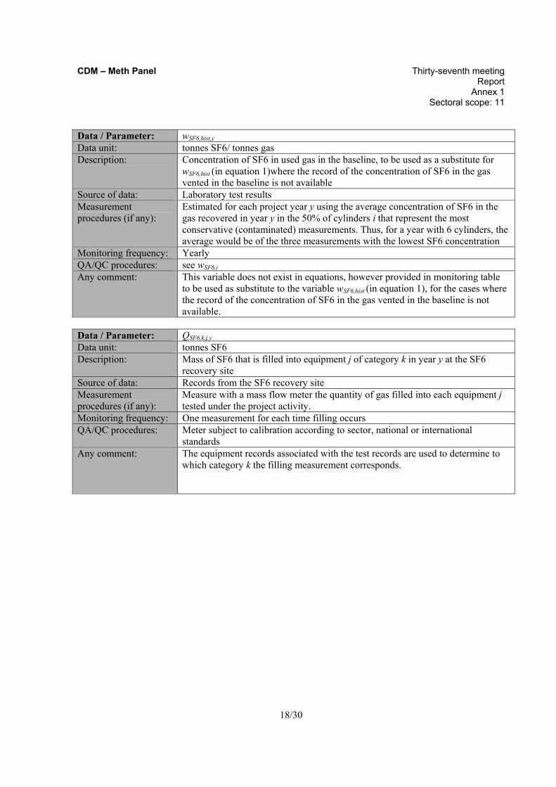
Data / Parameter: wSF6,hist,y
Data unit: tonnes SF6/ tonnes gas Description: Concentration of SF6 in used gas in the baseline, to be used as a substitute for
wSF6,hist (in equation 1)where the record of the concentration of SF6 in the gas vented in the baseline is not available
Source of data: Laboratory test results Measurement procedures (if any):
Estimated for each project year y using the average concentration of SF6 in the gas recovered in year y in the 50% of cylinders i that represent the most conservative (contaminated) measurements. Thus, for a year with 6 cylinders, the average would be of the three measurements with the lowest SF6 concentration
Monitoring frequency: Yearly QA/QC procedures: see wSF6,i Any comment: This variable does not exist in equations, however provided in monitoring table
to be used as substitute to the variable wSF6,hist (in equation 1), for the cases where the record of the concentration of SF6 in the gas vented in the baseline is not available.
Data / Parameter: QSF6,k,j,y Data unit: tonnes SF6 Description: Mass of SF6 that is filled into equipment j of category k in year y at the SF6
recovery site Source of data: Records from the SF6 recovery site Measurement procedures (if any):
Measure with a mass flow meter the quantity of gas filled into each equipment j tested under the project activity.
Monitoring frequency: One measurement for each time filling occurs QA/QC procedures: Meter subject to calibration according to sector, national or international
standards Any comment: The equipment records associated with the test records are used to determine to
which category k the filling measurement corresponds.
CDM – Meth Panel Thirty-seventh meeting Report Annex 1 Sectoral scope: 11
19/30
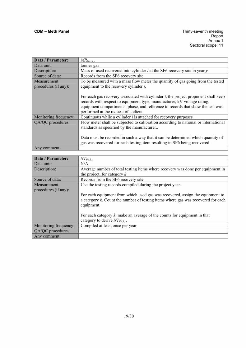
Data / Parameter: MRGas,i,y Data unit: tonnes gas Description: Mass of used recovered into cylinder i at the SF6 recovery site in year y Source of data: Records from the SF6 recovery site Measurement procedures (if any):
To be measured with a mass flow meter the quantity of gas going from the tested equipment to the recovery cylinder i. For each gas recovery associated with cylinder i, the project proponent shall keep records with respect to equipment type, manufacturer, kV voltage rating, equipment compartments, phase, and reference to records that show the test was performed at the request of a client
Monitoring frequency: Continuous while a cylinder i is attached for recovery purposes QA/QC procedures: Flow meter shall be subjected to calibration according to national or international
standards as specified by the manufacturer.. Data must be recorded in such a way that it can be determined which quantity of gas was recovered for each testing item resulting in SF6 being recovered
Any comment: Data / Parameter: NTPJ,k,y Data unit: N/A Description: Average number of total testing items where recovery was done per equipment in
the project, for category k Source of data: Records from the SF6 recovery site Measurement procedures (if any):
Use the testing records compiled during the project year For each equipment from which used gas was recovered, assign the equipment to a category k. Count the number of testing items where gas was recovered for each equipment. For each category k, make an average of the counts for equipment in that category to derive NTPJ,k,y.
Monitoring frequency: Compiled at least once per year QA/QC procedures: Any comment:

CDM – Meth Panel Thirty-seventh meeting Report Annex 1 Sectoral scope: 11
20/30
Data / Parameter: i Data unit: - Description: Sub-index used for each cylinder that completed a recovery-reclamation cycle
included in the estimation of emissions avoided for the year y. Source of data: Records from the SF6 recovery site and SF6 reclamation site Measurement procedures (if any):
Each recovery cylinder should be clearly identified and marked so that it can be uniquely identified and associated with gas recovery operations (MRgas,i), gas weight (MSGas,i), wSF6,i, and gas injected (MIgas,i)
Monitoring frequency: - QA/QC procedures: When used gas is filled into a recovery cylinder, weighed, and sent for
reclaiming, the activity should be noted using the cylinder identification information
Any comment: Recovery cylinders must be visibly distinguishable from new gas cylinders. Records from both sites should coincide An individual cylinder may be used more than one time per year, i.e. it may go through the recovery-reclamation process more than once. However, the labelling will show the unique identity of each cylinder as it is involved in one recovery-reclamation process
Data / Parameter: n Data unit: - Description: Number of cylinders that completed a recovery-reclamation cycle in the year y.
Only these cylinders are eligible to be included in the estimation of emissions avoided for the year y
Source of data: Records from the SF6 recovery site and SF6 reclamation site Measurement procedures (if any):
-
Monitoring frequency: - QA/QC procedures: The appropriate site must keep record of each cylinder i for which recovery has
been completed, for which reclamation has been completed, and the cylinder i identification information
Any comment: Records from both sites should coincide. In the case in which a cylinder has not completed reclamation in year y, it will have to be accounted in year y+1 as mentioned in Step 2 of baseline emissions

CDM – Meth Panel Thirty-seventh meeting Report Annex 1 Sectoral scope: 11
21/30
Data / Parameter: MSGas,i,y Data unit: tonnes gas Description: Mass of used gas stored in recovery cylinder i in year y Source of data: Records from SF6 recovery site Measurement procedures (if any):
Measuring device:weigh scale Mass is the weight of the cylinder i at the beginning of the recovery cycle (when the cylinder i is empty) minus the weight of the cylinder i at the end of the recovery cycle (when the cylinder i is ready to be sent to reclamation).
Monitoring frequency: Calculated once per cylinder QA/QC procedures: Weigh scale shall be subjected to calibration according to national or
international standards as specified by the manufacturer.. Data must be recorded in such a way that it can be determined which quantity of gas was recovered for each testing item resulting in SF6 being recovered. The monitored values should be kept along with: a) date and time when the measurement was taken b) cylinder i identification information
Any comment: Data / Parameter: wSF6,i Data unit: tonnes SF6/ tonnes gas Description: Concentration of SF6 in the cylinder i Source of data: laboratory test result Measurement procedures (if any):
The proportion must be measured for each cylinder of used gas collected, using a laboratory test. Gas chromatography is an appropriate method to determine wSF6,i
Monitoring frequency: Once per cylinder QA/QC procedures: Test according to ASTM D2685 or other applicable national or international
standards Any comment: Given that the recovery and reclamation process are batch processes, and that the
concentration of SF6 in the used gas remains constant after recovery and before reclamation, wSF6,c needs to be measured only once per cylinder to determine the proportion of SF6 in the gas contained in that cylinder The PDD should include the minimum specification for used SF6 gas reclamation at the SF6 reclamation site
CDM – Meth Panel Thirty-seventh meeting Report Annex 1 Sectoral scope: 11
22/30
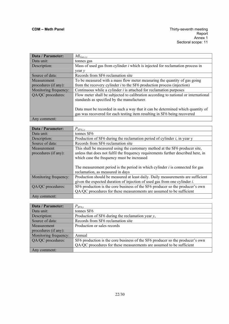
Data / Parameter: MIGas,i,y Data unit: tonnes gas Description: Mass of used gas from cylinder i which is injected for reclamation process in
year y Source of data: Records from SF6 reclamation site Measurement procedures (if any):
To be measured with a mass flow meter measuring the quantity of gas going from the recovery cylinder i to the SF6 production process (injection)
Monitoring frequency: Continuous while a cylinder i is attached for reclamation purposes QA/QC procedures: Flow meter shall be subjected to calibration according to national or international
standards as specified by the manufacturer. Data must be recorded in such a way that it can be determined which quantity of gas was recovered for each testing item resulting in SF6 being recovered
Any comment: Data / Parameter: PSF6,i,y Data unit: tonnes SF6 Description: Production of SF6 during the reclamation period of cylinder i, in year y Source of data: Records from SF6 reclamation site Measurement procedures (if any):
This shall be measured using the customary method at the SF6 producer site, unless that does not fulfil the frequency requirements further described here, in which case the frequency must be increased The measurement period is the period in which cylinder i is connected for gas reclamation, as measured in days
Monitoring frequency: Production should be measured at least daily. Daily measurements are sufficient given the expected duration of injection of used gas from one cylinder i.
QA/QC procedures: SF6 production is the core business of the SF6 producer so the producer’s own QA/QC procedures for these measurements are assumed to be sufficient
Any comment: Data / Parameter: PSF6,y Data unit: tonnes SF6 Description: Production of SF6 during the reclamation year y, Source of data: Records from SF6 reclamation site Measurement procedures (if any):
Production or sales records
Monitoring frequency: Annual QA/QC procedures: SF6 production is the core business of the SF6 producer so the producer’s own
QA/QC procedures for these measurements are assumed to be sufficient Any comment:
CDM – Meth Panel Thirty-seventh meeting Report Annex 1 Sectoral scope: 11
23/30
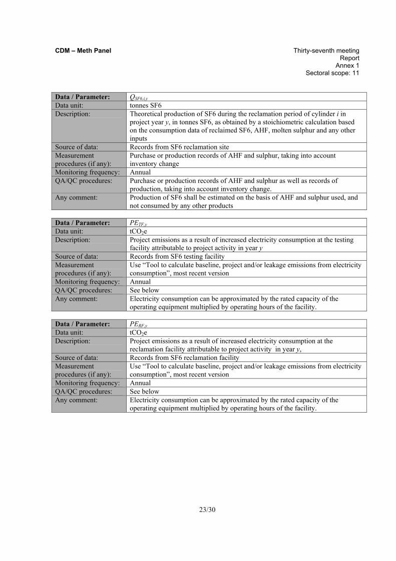
Data / Parameter: QSF6,i,y Data unit: tonnes SF6 Description: Theoretical production of SF6 during the reclamation period of cylinder i in
project year y, in tonnes SF6, as obtained by a stoichiometric calculation based on the consumption data of reclaimed SF6, AHF, molten sulphur and any other inputs
Source of data: Records from SF6 reclamation site Measurement procedures (if any):
Purchase or production records of AHF and sulphur, taking into account inventory change
Monitoring frequency: Annual QA/QC procedures: Purchase or production records of AHF and sulphur as well as records of
production, taking into account inventory change. Any comment: Production of SF6 shall be estimated on the basis of AHF and sulphur used, and
not consumed by any other products Data / Parameter: PETF,y Data unit: tCO2e Description: Project emissions as a result of increased electricity consumption at the testing
facility attributable to project activity in year y Source of data: Records from SF6 testing facility Measurement procedures (if any):
Use “Tool to calculate baseline, project and/or leakage emissions from electricity consumption”, most recent version
Monitoring frequency: Annual QA/QC procedures: See below Any comment: Electricity consumption can be approximated by the rated capacity of the
operating equipment multiplied by operating hours of the facility. Data / Parameter: PERF,y Data unit: tCO2e Description: Project emissions as a result of increased electricity consumption at the
reclamation facility attributable to project activity in year y, Source of data: Records from SF6 reclamation facility Measurement procedures (if any):
Use “Tool to calculate baseline, project and/or leakage emissions from electricity consumption”, most recent version
Monitoring frequency: Annual QA/QC procedures: See below Any comment: Electricity consumption can be approximated by the rated capacity of the
operating equipment multiplied by operating hours of the facility.

CDM – Meth Panel Thirty-seventh meeting Report Annex 1 Sectoral scope: 11
24/30
Data / Parameter: EXCSF6,y Data unit: tonnes SF6 Description: Quantity of SF6 which was being injected to the reclamation facility during
exceptional events occurred in year y Source of data: Records from SF6 reclamation site Measurement procedures (if any):
The project proponent must record the date and time of any exceptional event that occurs in year y that results in the unusual emission of SF6 The SF6 quantity (EXCSF6,y) from any reclamation that coincides with the event must be considered as project emissions (PEEXC,y) For example, if a cylinder of used gas was being reclaimed when the event occurred, then the total amount of gas from the cylinder between 5 hours prior to the event and until the time that the injection line was shut off must be considered as EXCSF6,y. The total amount of gas is to be taken from the continuous measurement of the flow meter on the injection line used to determine MIGas,i
Monitoring frequency: Quantity shall be determined for every exceptional event in year y QA/QC procedures: Furthermore, the project proponent may be asked by the verifier to demonstrate
records of production of SF6 in year y (PSF6,y,i) to demonstrate the functioning of the SF6 production at the SF6 reclamation site during periods of reclamation, and a reason shall be given for any low production outliers that do not coincide with a recorded exceptional event
Any comment: Data / Parameter: LETrans,y Data unit: tCO2e Description: Emissions from transport of the cylinders from the recovery site to the site of
reclamation in year y Source of data: Records from SF6 recovery site or SF6 reclamation site Measurement procedures (if any):
Use the “Tool to calculate project or leakage CO2 emissions from fossil fuel combustion” or the “Baseline emissions accounting method” of AMS-III.C. Emission reductions by low-greenhouse gas emitting vehicles
Monitoring frequency: QA/QC procedures: Any comment: Does not need to be monitored if it is demonstrated in the PDD that these
emissions are marginal according to Step 1 of the leakage section
IV. REFERENCES AND ANY OTHER INFORMATION
Not applicable.

CDM – Meth Panel Thirty-seventh meeting Report Annex 1 Sectoral scope: 11
25/30
Annex A
Under Method 2, a best estimate of the historical baseline venting amount (TISF6,used,t ) per testing item is made by using historical records of testing to determine when venting must have occurred in the past, and then by assigning an SF6 amount to each of the instances of venting based on either manufacturer specification/nameplate SF6 capacities or a list of standard SF6 capacities and information about the equipment as included in the historical records.
Step 1: Creation of CDM Records
Action: Gather the historical records of testing, where the tests were Electrical Tests performed on medium- and high-voltage rated equipment that uses SF6 gas, as a part of a certification or rating process or during development or production, for the baseline year.
• These records must include, at a minimum, the following information about the test: reference to the client request for the test, list of the tests & testing items undertaken and their results, reference to the testing procedure/ standards followed (e.g. IEC 62271-200), reference to the report(s) produced for the client as a result;
• These records must include, at a minimum, information about the equipment tested: manufacturer, equipment type, kV voltage rating, equipment compartments, phase.
Create CDM Records: Create the following records to be made available at validation:
• Prepare an overview of where historical records are kept and in what form, for easy reference of the validating Designated Operational Entity (DOE);
• Database showing, at a minimum, a summary of all the information described under “Action” for every test and testing item t to be included in the historical baseline;
Step 2: Use of Decision-making flowchart
Action: Use the default decision-making flowchart for the destination of used SF6 gas in the baseline, as contained in this annex. This chart is used as a key to interpret the historical testing records to determine the destination for the used SF6 gas. The flowchart indicates when eligible SF6 venting would occur during a test. The eligible venting can be determined from examining the historical test records and comparing the record for each testing item to the flowchart. The output of the Decision-making flowchart will therefore be the destination of the SF6 after each testing item (i.e., remained in equipment or vented).
The default decision making chart is shown below. For each testing record, project proponents should follow through the chart to the end to identify eligible venting events that occurred. The PDD shall describe the signals from the testing records that indicate when the conditions of the flow chart are fulfilled (to be used in the reconstruction), including the conditions that demonstrate that when a testing item needed to be repeated and when an equipment was dismantled.

CDM – Meth Panel Thirty-seventh meeting Report Annex 1 Sectoral scope: 11
26/30
Default decision-making flowchart
For any project, it can be assumed that gas is removed from equipment when a test is finished (all testing items of an equipment completed), or when a testing item must be repeated and the equipment must be dismantled prior to repetition. SF6 gas used in a test may be contaminated to an unknown degree. The condition required to be met for above assumption is that the gas used during a test is not reused in further tests, since the SF6 gas may be contaminated to an unknown degree, it will therefore not be reused in the absence of recovery and reclamation..

CDM – Meth Panel Thirty-seventh meeting Report Annex 1 Sectoral scope: 11
27/30
Examples of applying the Decision making flowchart are as follows:
Example 1: The testing record shows that one test comprising four testing items was performed on the equipment X. No testing items were repeated. Therefore, it is assumed that used SF6 gas was removed (vented) once, after the last testing item of the test, from this equipment X.
Example 2: The testing record shows that one test comprising six testing items were performed on the equipment Z. The first testing item was invalid according to the record due to an assembly error. As a result the equipment was dismantled and then reassembled prior to repeating the testing item. Therefore, it is assumed that used SF6 was removed twice, once after the invalid testing item 1 and once after the last testing item of the test.
In the case that the decision making for historical venting differs from the default, project proponents may submit an alternative method via a request for deviation or revision. The decision making flowchart should reflect the current practice at the recovery site as documented in response to the identification of the baseline scenario section. Create CDM Records: Create the following records, as necessary to be made available at validation:
• The Decision making flow chart that was used for reconstructing the baseline; • List of the signals from the testing records that indicate when the conditions of the flow chart are
fulfilled (to be used in the reconstruction), so that an external party could find the same resulting historical baseline if they were to review all the historical year testing records.
Step 3: Establish SF6 capacities
Action: Next, capacity of SF6 in each of the equipment tested needs to be established, to derive both historic and current situations. For this purpose, the following options shall be pursued.
a) Use the manufacturer specification or nameplate (if available);
b) Use default capacities contained in Table B.1 and B.2 in Annex B of the methodology;
c) Develop a procedure to determine default SF6 capacities for the equipment covered by the project activity (this must be submitted as a request for deviation to the methodology).
The following guidelines apply when using the default capacities in Tables B.1 and B.2 from Annex B:
(1) For equipment of a rated voltage within the range of the default values provided, but not explicitly listed in the default table, the project proponent shall use the SF6 capacity for the closest lower rated equipment. For instance, if the equipment is rated at 123kV, the default capacity corresponding to 84kV must be used.
(2) For voltage ratings that are outside the range of default values provided, the project proponent shall follow the procedure contained in Annex B to determine default SF6 capacity, or use a default capacity of zero for lower ratings below the available range and the default capacity for highest rating available in table for higher ratings above the available range.

CDM – Meth Panel Thirty-seventh meeting Report Annex 1 Sectoral scope: 11
28/30
Create CDM Records: Create the following records to be made available at validation:
• The list of SF6 capacities that were used for reconstruction of the historical baseline.
Step 4: Obtain TISF6,used,t , the used SF6 gas vented during each testing item t
Action: For each test and testing item for which a record exists (Step 1), examine the testing item record and compare it to the Decision-making flowchart (Step 2) to determine the destination of used SF6 at the end of each testing item. Create CDM Records: Create the following records to be made available at validation:
• In the database described in Step 1, for every testing item t , add the result of the decision making flow chart (eligible or ineligible) and the signal in the testing record that provided this result. Indicate every testing item t that resulted in venting.
Step 5: Assign an SF6 capacity
Action: For every testing item t that resulted in eligible venting, assign an SF6 amount vented by assigning the corresponding SF6 capacity (Step 3) for the equipment type in question. The equipment type in question is determined from the equipment characteristics included in the testing record. Create CDM Records: Create the following records to be made available at validation:
• In the database described in Step 1, for every testing item t that resulted in venting, include the SF6 capacity as derived from the default list from Step 3. For every entry, there should be enough information in the database to be able to select the SF6 capacity shown from the list provided in Step 3.
Step 6: Sum
Sum all of the SF6 capacities, following equation 1 (Determine VSF6,hist). This equation also takes into account the SF6 content of the used gas, thereby accounting for the decomposition of SF6 during testing.
CDM – Meth Panel Thirty-seventh meeting Report Annex 1 Sectoral scope: 11
29/30
Annex B
Default SF6 Capacity Tables & Procedure to Estimate SF6 Capacity
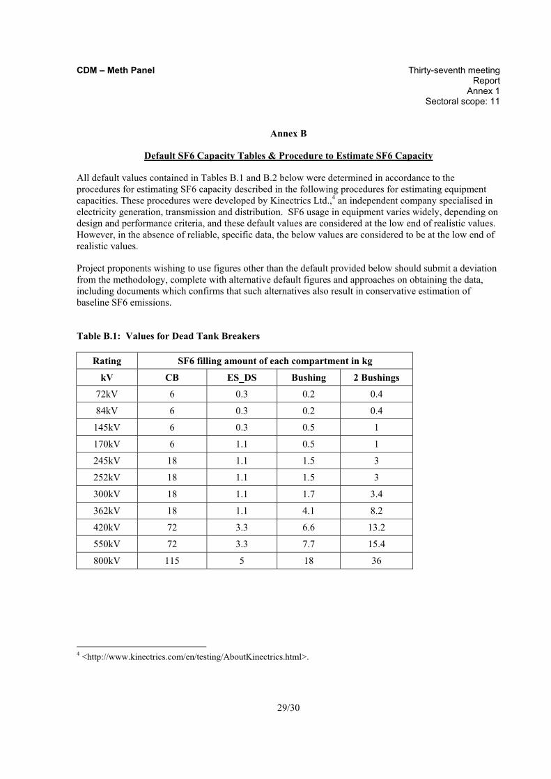
All default values contained in Tables B.1 and B.2 below were determined in accordance to the procedures for estimating SF6 capacity described in the following procedures for estimating equipment capacities. These procedures were developed by Kinectrics Ltd.,4 an independent company specialised in electricity generation, transmission and distribution. SF6 usage in equipment varies widely, depending on design and performance criteria, and these default values are considered at the low end of realistic values. However, in the absence of reliable, specific data, the below values are considered to be at the low end of realistic values.
Project proponents wishing to use figures other than the default provided below should submit a deviation from the methodology, complete with alternative default figures and approaches on obtaining the data, including documents which confirms that such alternatives also result in conservative estimation of baseline SF6 emissions.
Table B.1: Values for Dead Tank Breakers
4 <http://www.kinectrics.com/en/testing/AboutKinectrics.html>.
Rating SF6 filling amount of each compartment in kg
kV CB ES_DS Bushing 2 Bushings
72kV 6 0.3 0.2 0.4
84kV 6 0.3 0.2 0.4
145kV 6 0.3 0.5 1
170kV 6 1.1 0.5 1
245kV 18 1.1 1.5 3
252kV 18 1.1 1.5 3
300kV 18 1.1 1.7 3.4
362kV 18 1.1 4.1 8.2
420kV 72 3.3 6.6 13.2
550kV 72 3.3 7.7 15.4
800kV 115 5 18 36

CDM – Meth Panel Thirty-seventh meeting Report Annex 1 Sectoral scope: 11
30/30
Table B.2: Values for Live Tank Breakers
- - - - -
History of the document
Version Date Nature of revision(s) 01 EB 46, Annex #
25 March 2009 To be considered at EB 46.
Rating SF6 filling amount in kg
kV CB
72kV 1.5
84kV 1.5
145kV 2
170kV 2.5
245kV 4.8
252kV 4.8
300kV 5
362kV 8
420kV 8
550kV 10
CB: Circuit Breaker
ES : Earthing Switch
DS : Disconnected Switch