draft advisory circular - civil aviation safety … · advisory circular . ... cs&e cabin...
TRANSCRIPT

v1.0 – April 2015
Project Number: CS 13/12
DRAFT
AC 21-24
Flight recorder and underwater locating
device maintenance
ADVISORY CIRCULAR
FLIGHT RECORDERS AND UNDERWATER
LOCATING DEVICES REQUIREMENTS
Advisory Circulars are intended to provide advice and guidance to illustrate a means, but not necessarily the only
means, of complying with the Regulations, or to explain certain regulatory requirements by providing informative,
interpretative and explanatory material.
Advisory Circulars should always be read in conjunction with the relevant regulations.
Unless specified otherwise, all subregulations, regulations, divisions, subparts and parts
referenced in this AC are references to the Civil Aviation Safety Regulations 1998 (CASR 1998).
AC 21-24 v1.0 DRAFT April 2015 Page 1
Audience
This Advisory Circular (AC) applies to:
Subpart 21.B type certificate holders
Subpart 21.E supplemental type certificate (STC) holders
Subpart 21.M authorised persons
Subpart 21.J approved design organisations
Part 42 of the Civil Aviation Safety Regulations 1998 (CASR 1998) - Continuing
airworthiness management organisations
Part 145 - Approved maintenance organisations
Part 30 of the Civil Aviation Regulations 1988 (CAR 1988) maintenance certificate of
approval holder
Purpose
The purpose of this AC is to provide guidance maintenance of aircraft flight data recorders
(FDRs), cockpit voice recorders (CVRs) and underwater locating devices (ULDs). This AC does
not provide advice or standards for the installation of recorders and ULDs, however the contents
of this AC should be considered when preparing the instructions for continued airworthiness
(ICA) for a new installation.
For further information
For further information on this AC, contact the Civil Aviation Safety Authority's (CASA’s)
Airworthiness and Engineering Standards Branch (telephone 131 757).

FLIGHT RECORDER AND UNDERWATER
LOCATING DEVICE MAINTENANCE
AC 21-24 v1.0 DRAFT April 2015 Page 2
Status
Version Date Details
1.0 This AC was compiled with information from Civil Aviation Advisory Publication (CAAP) 42L-4(0), 42L-7(0) and 42L-8(0). Any information was updated to latest technical requirements. Added additional information on using FDRs for a flight data analysis program (FDAP).
FLIGHT RECORDERS AND UNDERWATER
LOCATING DEVICES REQUIREMENTS
AC 21-24 v1.0 DRAFT April 2015 Page 3
Contents
1 Reference material 5
1.1 Acronyms 5
1.2 Definitions 7
1.3 References 8
2 Flight data recorders 10
2.1 Various types and uses for FDRs 10
2.2 Existing standards 14
2.3 Installation information 16
2.4 FDR maintenance program 16
2.5 Minimum equipment list considerations 18
2.6 Documentation 18
3 Combination recorders 20
3.1 Background 20
3.2 Installation information 20
4 Recorder independent power supply 21
4.1 Background 21
4.2 Existing Standards 21
4.3 Installation information 21
4.4 Instructions for continued airworthiness 21
5 Lightweight flight recorders 22
5.1 Background 22
5.2 Existing standards 22
5.3 Installation information 22
6 Cockpit voice recorders 24
6.1 Background 24
6.2 Existing standards 24
6.3 Recommended functional test 25
6.4 Operators maintenance program 26
6.5 Effects of modifications 26
6.6 First of type/model CVR installation 27
7 Underwater locating device 28
FLIGHT RECORDERS AND UNDERWATER
LOCATING DEVICES REQUIREMENTS
AC 21-24 v1.0 DRAFT April 2015 Page 4
7.1 Background 28
7.2 Existing standards 28
7.3 Maintenance program 29
7.4 Installation information 29
Appendix A Cockpit voice recorder flight test 30
Appendix B Typical flight data recorder system check procedures 34

FLIGHT RECORDERS AND UNDERWATER
LOCATING DEVICES REQUIREMENTS
AC 21-24 v1.0 DRAFT April 2015 Page 5
1 Reference material
1.1 Acronyms
The acronyms and abbreviations used in this AC are listed in the table below.
Acronym Description
AC Advisory Circular
AMC Acceptable Means of Compliance
ATSB Australian Transport Safety Bureau
BITE Built-In Test Equipment
CAAP Civil Aviation Advisory Publication
CAO Civil Aviation Order
CAP Civil Aviation Publication (CAA UK)
CAR Civil Aviation Regulations 1988
CASA Civil Aviation Safety Authority
CASR Civil Aviation Safety Regulations 1998
CoA Certificate of Airworthiness
CS&E Cabin Systems and Equipment
CS-ETSO Certification Specifications - European Technical Standard Orders
CVR Cockpit Voice Recorder
EASA European Aviation Safety Agency
ED EUROCAE Document
ETSO European Technical Standard Order
EU Engineering Units
EUROCAE European Organisation for Civil Aviation Equipment
FDAU Flight Data Acquisition Unit
FAA Federal Aviation Administration (of the USA)
FDAP Flight Data Analysis Program
FDR Flight Data Recorder
GSE Ground Support Equipment
ICA Instructions for Continued Airworthiness
ICAO International Civil Aviation Organization
MEL Minimum Equipment List
MPS Minimum Performance Standards

FLIGHT RECORDERS AND UNDERWATER
LOCATING DEVICES REQUIREMENTS
AC 21-24 v1.0 DRAFT April 2015 Page 6
MTOW Maximum Take-Off Weight
OEM Original Equipment Manufacturer
QAR Quick Access Recorders
STC Supplemental Type Certificate
RIPS Recorder Independent Power Supply
RMT Rule Making Task
SMS Safety Management System
SoM System of Maintenance
SPO Specialised Air Operations
TC Type Certificate
TCAS Traffic Collision Avoidance System
ToR Terms of Reference
TSO Technical Standard Order
ULD Underwater Locating Device

FLIGHT RECORDERS AND UNDERWATER
LOCATING DEVICES REQUIREMENTS
AC 21-24 v1.0 DRAFT April 2015 Page 7
1.2 Definitions
Terms that have specific meaning within this AC are defined in the table below.
Term Definition
Cockpit voice recorder A device that uses a combination of microphones and other audio and digital inputs to collect and record the aural environment of the cockpit and communications to, from and between the flight crew members.
Combination recorder A single recorder that combines the functions of two or more accident recording functions in a single crash protected box.
Correlation The parallel relationship of two or more corresponding events.
Data conversion Conversion of binary data to a scaled value.
Download Copying the digital data (also known as raw data) stored in the crash protected memory module for replaying at a later time.
Drop out Loss of synchronisation, corrupted bit or data word that was recorded and cannot be correctly recovered by data recovery and analysis system.
Engineering units Scaled value relating to the data source (e.g. altitude scaled to feet, airspeed scaled to knots).
Flight data recorder A device or devices that uses a combination of data providers to collect and record parameters that reflect the state and performance of an aircraft.
Flight recorder Any type of recorder installed in the aircraft for the purpose of complementing accident/incident investigation or flight analysis.
Functional check A quantitative check to determine if one or more functions of an item performs within specified limits. When applied to an FDR parameter, the functional check determines that the recorded parameter is within the limits (range, accuracy, sampling rate, and resolution) specified in the operating rule. The maintenance functional check should exercise the recording system from the sensor or transducer to check the range, accuracy, resolution, and sampling rate of the recorded data.
Operational check An operational check is a task to determine that an item is fulfilling its intended purpose. This task does not require quantitative tolerances as it is a failure finding task. When applied to an FDR, the operational check determines that the FDR is active and recording each parameter value within the normal operating range of the sensor. The operational check must also verify verifies each electrical interface to the FDR. A check to determine the reasonableness and quality of the data being recorded is considered an operational check.
Parameter Aircraft system or motion required to be recorded (e.g. for control surface – flap position and for aircraft velocity – airspeed).
Quality Amount of data that cannot be recovered or is corrupted.
Reasonableness An off-airplane review of recorded data to assess the overall health of the recorded system parameters. The recorded parameter values are assessed against expected magnitude, direction and rates of change. For further information see Federal Aviation Administration (FAA) AC 20-141B.
Recorder independent power supply (RIPS)
A supplemental energy source that supplies direct current voltage to applicable aircraft recorder(s), for a specified duration whenever the primary aircraft power is removed from the recorder(s).

FLIGHT RECORDERS AND UNDERWATER
LOCATING DEVICES REQUIREMENTS
AC 21-24 v1.0 DRAFT April 2015 Page 8
Term Definition
Simulation The use of a laboratory-installed system of avionic components (test bench) representative of the aircraft in which the recording system is to be certified. The test bench may be controlled by a computer-based system including analogue and discrete inputs, to create specific operating conditions, such as 90° pitch up, or other conditions that cannot be tested in flight or are difficult to test on the aircraft. The test bench should be configured so the computer or analogue inputs to the system drive the instruments and displays in a way representative of the aircraft. All avionic components installed in the test bench should be either of production standard or representative of the final production configuration.
Solid state An electronic device that is capable of performing a function without the use of moving parts, using semiconductor material or similar.
Stimulation The use of test equipment, traceable to a known standard, to induce aircraft systems to produce a specific result.
Synchronisation A technique to align two independent events to a common point in time.
Test A means of demonstrating compliance, using a test aircraft in a configuration representative of the configuration to be certified, in a ground and/or flight environment.
1.3 References
Regulations
Regulations are available on the ComLaw website http://www.comlaw.gov.au/Home
Document Title
Part 21 of CASR Certification and airworthiness requirements for aircraft and parts
Part 42 of CASR Continuing Airworthiness requirements for aircraft and aeronautical products
Part 145 of CASR Continuing airworthiness - Part 145 approved maintenance organisations
Part 30 of CAR Certificates of approval
Part 4A of CAR Maintenance
Civil Aviation Order (CAO) 20.18
Aircraft equipment - Basic operational requirements
CAO 100.5 General requirements in respect of maintenance of Australian aircraft
CAO 103.19 Equipment standards - flight data recorders
CAO 103.20 Equipment standards - cockpit voice recorders
Advisory material
CASA’s advisory material is available at http://www.casa.gov.au/scripts/nc.dll?WCMS:STANDARD::pc=PC_90902
Document Title

FLIGHT RECORDERS AND UNDERWATER
LOCATING DEVICES REQUIREMENTS
AC 21-24 v1.0 DRAFT April 2015 Page 9
Document Title
Annex 6 to the Convention on International Civil Aviation (Chicago Convention)
Operation of Aircraft
CAAP SMS-4(0) Guidance on the establishment of a Flight Data Analysis Program (FDAP) Safety Management Systems (SMS)
CAAP 232A-1 Administration of Aircraft Related Ground Support Network Security Programs
CAAP 37-1 Minimum equipment lists (MEL)
European Aviation Safety Agency (EASA) Specialised Air Operations (SPO).IDE.A.140
Cockpit voice recorder
EASA SPO.IDE.A.145 Flight data recorder
EASA SPO.IDE.A.155 Flight data recorder and cockpit voice combination recorder
FAA AC 20-141B Airworthiness and Operational Approval of Digital Flight Data Recorder
UKCAA CAP 739 Flight Data Monitoring
AO-2014-083 Loss of control involving a Cirrus SR22, N802DK, ATSB Transport Safety Report
FAA AC 20-168 Certification Guidance for Installation of Non-Essential, Non-Required Aircraft Cabin Systems & Equipment (CS&E)
SAE Aerospace Standard (AS) 8045a
Minimum Performance Standard for Underwater Locating Devices (Acoustic) (Self-Powered)
Technical Standard Order (TSO)-C121b
Underwater Locating Devices (Acoustic) (Self-Powered)
ETSO-C121b Underwater Locating Devices
TSO-C200 Airframe Low Frequency Underwater Locating Devices (Acoustic) (Self Powered)
ETSO-C200 Low-frequency Underwater Locating Device (ULD)
SAE AS 6254 Minimum Performance Standard for Low Frequency Underwater Locating Devices (Acoustic) (Self-Powered)
EASA Terms of Reference (ToR) RMT.0271 & 0272
Inflight recording for light aircraft
ARINC 647A Flight Recorder Electronic Documentation
Notice for Aircraft Flight Recorder and Cockpit Voice Recorder
Federal Register / Vol. 60, No. 74 / Tuesday, April 18, 1995 / Notices 19443
FLIGHT RECORDERS AND UNDERWATER
LOCATING DEVICES REQUIREMENTS
AC 21-24 v1.0 DRAFT April 2015 Page 10
2 Flight data recorders
2.1 Various types and uses for FDRs
2.1.1 Background
2.1.1.1 Historically the principal purpose of FDRs was to assist accident investigators to
determine the cause of air crashes. This was possible by recovering the FDR and
analysing the recorded flight data. FDRs proved very useful in providing a better
understanding of serious incidents.
2.1.1.2 In the early 1970s, a number of progressive operators appreciated the capabilities of
FDRs and the valuable insights they could provide for the conduct of safe flight.
2.1.1.3 Regularly gathering and analysing flight data from the flight recorders can reveal useful
information that can assist in monitoring operational efficiency. It also provides
performance information of airframes and engines that can assist in continuing
airworthiness.
2.1.2 Flight data analysis
2.1.2.1 Today it is realised by aviation agencies and airlines alike, that the practice of routinely
analysing recorded data from routine operations is a cornerstone in support of their
accident prevention programs. Rather than reacting to serious incidents, operators have
a very useful tool to proactively monitor the aircraft operation to identify safety hazards
and mitigate the potential risks.
2.1.2.2 The analysis of FDRs is done by an FDAP. This is a pro-active, non-punitive program
for gathering and analysing data recorded during routine flights to improve flight crew
performance, operating procedures, flight training, air traffic control procedures, air
navigation services, or aircraft maintenance and design.
2.1.2.3 Information from an operator's FDAP can assist in:
detect exceedances or other related events
routine data measurements
incident investigations
continued airworthiness investigations.
Note: For further information on FDAPs see CAAP SMS-4
2.1.2.4 Solid state recorders have been successfully used in an operator's FDAP. It is not
recommended to use magnetic storage medium recorders for an operator's FDAP
downloads as playback will affect serviceability. For further information on standards for
solid state recorders see paragraph 2.2 of this AC.
2.1.2.5 Rather than using the FDR to directly access the stored data, quick access recorders
(QARs) provide a way to easily obtain the data for an operator's FDAP. QAR
technology has evolved with many different methods available. FAA AC 20-168 is
acceptable guidance material for the installation of QAR equipment.
FLIGHT RECORDERS AND UNDERWATER
LOCATING DEVICES REQUIREMENTS
AC 21-24 v1.0 DRAFT April 2015 Page 11
2.1.2.6 Wireless QARs can transmit data using mobile phone or wifi technologies and security
of sensitive flight data should be protected from general public access. CAAP 232A-1
provides guidance material for security of data.
2.1.2.7 There is a selection of Original Equipment Manufacturer (OEM) specified and
proprietary devices available to perform this FDAP functions. Equipment not specified
by the OEM may be used if it can be proven that it will fulfil the requirements. The
advantage of the proprietary devices is that they display the information in both digital
format and engineering units (EU), which can assist in troubleshooting service
difficulties.
2.1.2.8 Any alternate tooling or test equipment that is not specified by the aircraft manufacturer
requires approval.
2.1.3 Types of recorders - Annex 6
Annex 6 to the Chicago Convention classifies FDRs aircraft by type depending upon the number of parameters and the duration required for the retention of the recorded information. (see Table 1):

FLIGHT RECORDERS AND UNDERWATER
LOCATING DEVICES REQUIREMENTS
AC 21-24 v1.0 DRAFT April 2015 Page 12
Table 1: ICAO classification of FDRs
FDR Type Use Maximum Take-off Weight (MTOW)
Recording duration
Parameters categories
Number of parameters
Type I Fixed wing >27,000 kg 25 hours flight path, speed, attitude, engine power, configuration and operation
First 32 parameters of Table A8-1 in Annex 6 Part I
Type IA Fixed wing 5,700 kg 25 hours flight path, speed, attitude, engine power, configuration and operation
First 78 parameters of Table A8-1 in Annex 6 Part I
Type II Fixed wing 5,700 to 27,000 kg
25 hours flight path, speed, attitude, engine power and configuration of lift and drag devices
First 16 parameters of Table A8-1 in Annex 6 Part I
Type IIA Fixed wing <5,700 kg 30 minutes Same as Type II and retain information from preceding take-off for calibration
First 16 parameters of Table A8-1 in Annex 6 Part I
Type IV Rotorcraft >7,000 kg 10 hours flight path, speed, attitude, engine power and operation
First 30 parameters of Table A4-1 in Annex 6 Part III
Type IVA Rotorcraft >3,175 kg 10 hours flight path, speed, attitude, engine power, configuration and operation
First 48 parameters of Table A4-1 in Annex 6 Part III
Type V Rotorcraft 3,175 to 7,000 kg 10 hours flight path, speed, attitude, engine power
First 15 parameters of Table A4-1 in Annex 6 Part III

FLIGHT RECORDERS AND UNDERWATER
LOCATING DEVICES REQUIREMENTS
AC 21-24 v1.0 DRAFT April 2015 Page 13
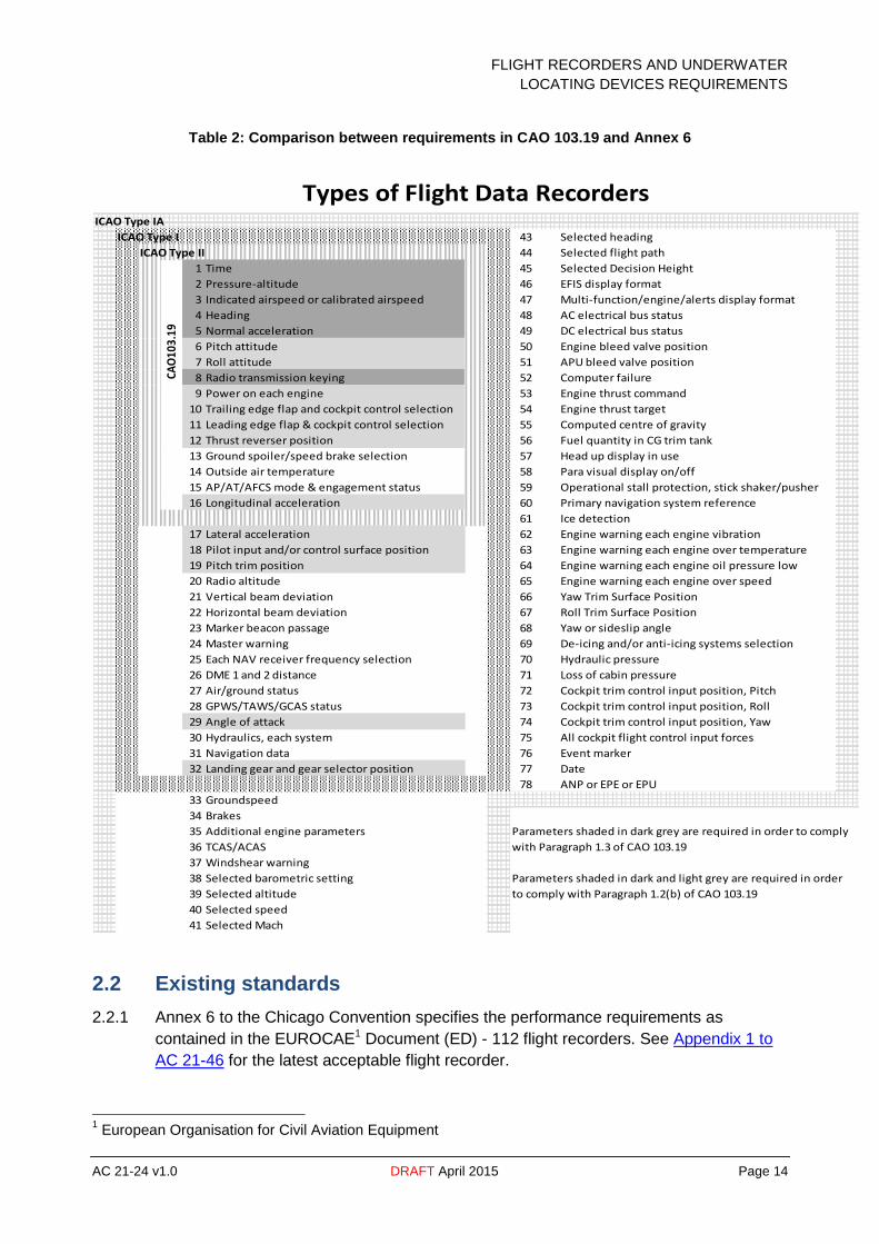
2.1.4 Table 2 illustrates the difference between the requirements in accordance with
Paragraph 1.2b and 1.3 of CAO 103.19 to the International Standards in Annex 6 to the
Chicago Convention. Parameters shaded in dark grey are minimum number of
parameters required to comply with Paragraph 1.3 of CAO 103.19. Both dark grey and
light grey shaded parameters are the minimum number of parameters required to
comply with subparagraph 1.2 (b) of CAO 103.19. The use of further parameters
beyond the minimum requirements of CAO 103.19 will capture more useful data for an
operator's FDAP.
2.1.5 The adoption of the different types of FDRs, as detailed in Parts I and III of Annex 6 to
the Chicago Convention, is undergoing review as part of the changes to the CASA
Flight Operations regulations development.
FLIGHT RECORDERS AND UNDERWATER
LOCATING DEVICES REQUIREMENTS
AC 21-24 v1.0 DRAFT April 2015 Page 14
Table 2: Comparison between requirements in CAO 103.19 and Annex 6
ICAO Type IA
ICAO Type I 43 Selected heading
44 Selected flight path
1 Time 45 Selected Decision Height
2 Pressure-altitude 46 EFIS display format
3 Indicated airspeed or calibrated airspeed 47 Multi-function/engine/alerts display format
4 Heading 48 AC electrical bus status
5 Normal acceleration 49 DC electrical bus status
6 Pitch attitude 50 Engine bleed valve position
7 Roll attitude 51 APU bleed valve position
8 Radio transmission keying 52 Computer failure
9 Power on each engine 53 Engine thrust command
10 Trailing edge flap and cockpit control selection 54 Engine thrust target
11 Leading edge flap & cockpit control selection 55 Computed centre of gravity
12 Thrust reverser position 56 Fuel quantity in CG trim tank
13 Ground spoiler/speed brake selection 57 Head up display in use
14 Outside air temperature 58 Para visual display on/off
15 AP/AT/AFCS mode & engagement status 59 Operational stall protection, stick shaker/pusher
16 Longitudinal acceleration 60 Primary navigation system reference
61 Ice detection
17 Lateral acceleration 62 Engine warning each engine vibration
18 Pilot input and/or control surface position 63 Engine warning each engine over temperature
19 Pitch trim position 64 Engine warning each engine oil pressure low
20 Radio altitude 65 Engine warning each engine over speed
21 Vertical beam deviation 66 Yaw Trim Surface Position
22 Horizontal beam deviation 67 Roll Trim Surface Position
23 Marker beacon passage 68 Yaw or sideslip angle
24 Master warning 69 De-icing and/or anti-icing systems selection
25 Each NAV receiver frequency selection 70 Hydraulic pressure
26 DME 1 and 2 distance 71 Loss of cabin pressure
27 Air/ground status 72 Cockpit trim control input position, Pitch
28 GPWS/TAWS/GCAS status 73 Cockpit trim control input position, Roll
29 Angle of attack 74 Cockpit trim control input position, Yaw
30 Hydraulics, each system 75 All cockpit flight control input forces
31 Navigation data 76 Event marker
32 Landing gear and gear selector position 77 Date
78 ANP or EPE or EPU
33 Groundspeed
34 Brakes
35 Additional engine parameters Parameters shaded in dark grey are required in order to comply
36 TCAS/ACAS with Paragraph 1.3 of CAO 103.19
37 Windshear warning
38 Selected barometric setting Parameters shaded in dark and light grey are required in order
39 Selected altitude to comply with Paragraph 1.2(b) of CAO 103.19
40 Selected speed
41 Selected Mach
Types of Flight Data Recorders
ICAO Type II
CAO
103.
19
2.2 Existing standards
2.2.1 Annex 6 to the Chicago Convention specifies the performance requirements as
contained in the EUROCAE1 Document (ED) - 112 flight recorders. See Appendix 1 to
AC 21-46 for the latest acceptable flight recorder.
1 European Organisation for Civil Aviation Equipment
FLIGHT RECORDERS AND UNDERWATER
LOCATING DEVICES REQUIREMENTS
AC 21-24 v1.0 DRAFT April 2015 Page 15
2.2.2 TSO-C51a or later amendment is still acceptable in accordance with CAO.103.19 (see
Note 1); however, this standard was cancelled by the FAA in 1995 due to less stringent
fire protection requirements (see Note 2). There are no amendments to the obsolete
TSO-C51a standard. The relevance of CAO 103.19 is undergoing review as part of the
changes to the CASA Flight Operations regulations development.
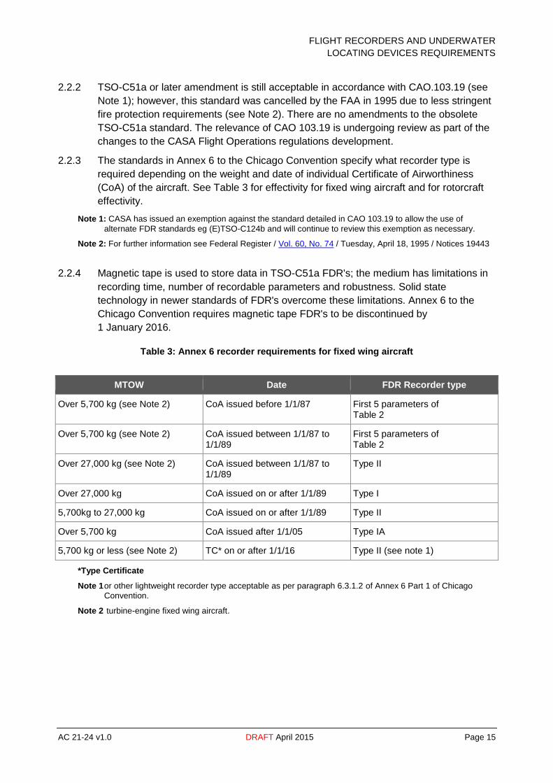
2.2.3 The standards in Annex 6 to the Chicago Convention specify what recorder type is
required depending on the weight and date of individual Certificate of Airworthiness
(CoA) of the aircraft. See Table 3 for effectivity for fixed wing aircraft and for rotorcraft
effectivity.
Note 1: CASA has issued an exemption against the standard detailed in CAO 103.19 to allow the use of
alternate FDR standards eg (E)TSO-C124b and will continue to review this exemption as necessary.
Note 2: For further information see Federal Register / Vol. 60, No. 74 / Tuesday, April 18, 1995 / Notices 19443
2.2.4 Magnetic tape is used to store data in TSO-C51a FDR's; the medium has limitations in
recording time, number of recordable parameters and robustness. Solid state
technology in newer standards of FDR's overcome these limitations. Annex 6 to the
Chicago Convention requires magnetic tape FDR's to be discontinued by
1 January 2016.
Table 3: Annex 6 recorder requirements for fixed wing aircraft
MTOW Date FDR Recorder type
Over 5,700 kg (see Note 2) CoA issued before 1/1/87 First 5 parameters of Table 2
Over 5,700 kg (see Note 2) CoA issued between 1/1/87 to 1/1/89
First 5 parameters of Table 2
Over 27,000 kg (see Note 2) CoA issued between 1/1/87 to 1/1/89
Type II
Over 27,000 kg CoA issued on or after 1/1/89 Type I
5,700kg to 27,000 kg CoA issued on or after 1/1/89 Type II
Over 5,700 kg CoA issued after 1/1/05 Type IA
5,700 kg or less (see Note 2) TC* on or after 1/1/16 Type II (see note 1)
*Type Certificate
Note 1 or other lightweight recorder type acceptable as per paragraph 6.3.1.2 of Annex 6 Part 1 of Chicago
Convention.
Note 2 turbine-engine fixed wing aircraft.

FLIGHT RECORDERS AND UNDERWATER
LOCATING DEVICES REQUIREMENTS
AC 21-24 v1.0 DRAFT April 2015 Page 16
Table 4: Annex 6 requirements for rotorcraft
MTOW Date FDR Recorder type
Over 7,000 kg or more 19 passengers
CoA issued on or after 1/1/89 Type IV
Over 3,180 kg CoA on or after 1/1/16 Type IVA
Between 2,250 kg to 3,180 kg TC issued on or after 1/1/18 Type IVA (see Note)
Note: or other lightweight recorder type acceptable as per paragraph 4.3.1.2.4 of Annex 6, Part 3 of Chicago
Convention.
2.3 Installation information
2.3.1 Chapter 2 of FAA AC 20-141B is acceptable guidance material for the installation of
FDRs.
2.3.2 Book 2 of the EASA Certification Specifications contains the acceptable means of
compliance (AMC) for installation of FDRs. The EASA AMCs detail placement of FDRs
as far aft as practicable to minimise the probability of damage from crash impact and
subsequent fire. AMC 25.1459 has additional requirements for detection of various FDR
failures by the built-in test equipment (BITE).
2.3.3 There can be a number of different combinations of FDR systems within the same
model that may record different parameters and utilise different transducers. Individual
aircraft configurations may have corresponding differences in the data conversion
algorithms.
2.3.4 Use of data conversion algorithms for the wrong aircraft configuration may provide data
that is misleading or incorrect, limiting the effectiveness of any analysis. This is an
important factor that should be considered when assessing the introduction into service
of a new aircraft. Therefore, it is advisable for the operator to check with the Australian
Transport Safety Bureau (ATSB) to determine if they have data conversion algorithms
for their particular FDR system in their aircraft type.
2.3.5 To meet the requirements of Paragraph 6.4 of CAO 20.18, a report from the
manufacturer needs to detail:
the part numbers of the FDR system
the conversion algorithms that convert the recorded data to EU
the original recorder or a copy of the recorded binary data for evaluation.
sufficient information to confirm that the FDR Run/Stop logic meets CAO 20.18
parameters.
2.4 FDR maintenance program
2.4.1 A maintenance program should be in place for each flight recorder system. This
program should be reviewed on a regular basis, especially when:
a new aircraft type is added to the fleet
FLIGHT RECORDERS AND UNDERWATER
LOCATING DEVICES REQUIREMENTS
AC 21-24 v1.0 DRAFT April 2015 Page 17
a change is made to flight recorder equipment
both airborne and Ground Support Equipment (GSE)
if an operator's FDAP is introduced or modified.
2.4.2 Adequate ICA would include administrative procedures for scheduling, accomplishing,
and recording maintenance actions on the FDR system.
2.4.3 The ICAs should also specify inspection items, establish time-in-service intervals for
maintenance, and provide the details of the proposed methods and procedures. For
further information on Installation Calibration and Correlation tests see paragraph II-6.3
of EUROCAE/ED-112. An example of an assessment method is included in Appendix 1
and readout in EU is recommended.
2.4.4 Any checks of the FDR system also include verification of sensor calibration (where
appropriate). Subparagraph 6.5 (c) of CAO 20.18 requires data from the last 2
occasions on which the FDR system was calibrated. This data may be requested by the
ATSB.
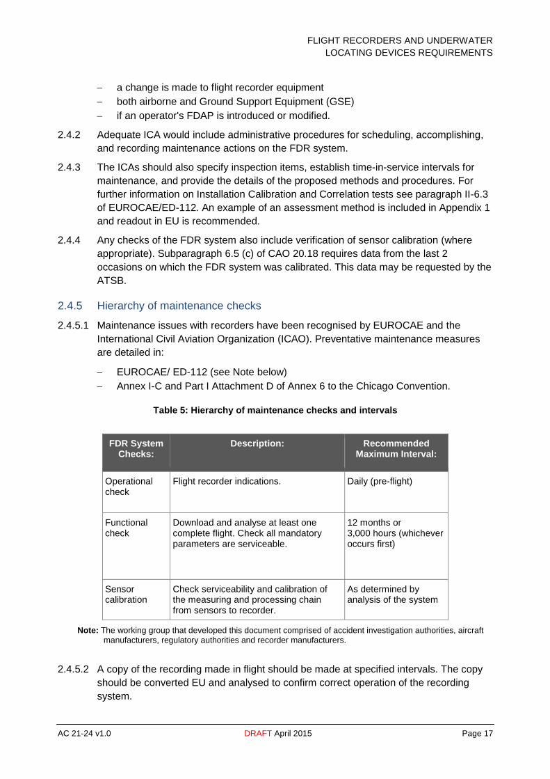
2.4.5 Hierarchy of maintenance checks
2.4.5.1 Maintenance issues with recorders have been recognised by EUROCAE and the
International Civil Aviation Organization (ICAO). Preventative maintenance measures
are detailed in:
EUROCAE/ ED-112 (see Note below)
Annex I-C and Part I Attachment D of Annex 6 to the Chicago Convention.
Table 5: Hierarchy of maintenance checks and intervals
FDR System Checks:
Description: Recommended Maximum Interval:
Operational check
Flight recorder indications. Daily (pre-flight)
Functional check
Download and analyse at least one complete flight. Check all mandatory parameters are serviceable.
12 months or 3,000 hours (whichever occurs first)
Sensor calibration
Check serviceability and calibration of the measuring and processing chain from sensors to recorder.
As determined by analysis of the system
Note: The working group that developed this document comprised of accident investigation authorities, aircraft
manufacturers, regulatory authorities and recorder manufacturers.
2.4.5.2 A copy of the recording made in flight should be made at specified intervals. The copy
should be converted EU and analysed to confirm correct operation of the recording
system.
FLIGHT RECORDERS AND UNDERWATER
LOCATING DEVICES REQUIREMENTS
AC 21-24 v1.0 DRAFT April 2015 Page 18
2.4.5.3 Inspection of the data may reveal defective or noisy sensors and indicate necessary
maintenance actions. Credit can be given where the serviceability of flight recorder
sensors is checked by inspection of the record produced by a maintenance provider.
2.4.5.4 A method should be used to verify the operation of the BITE for the FDR and optional
Flight Data Acquisition Unit (FDAU) prior to the first flight of the day. This can be
monitored by manual and/or automatic means. The BITE test may not necessarily
evaluate the quality of the recorded data.
2.4.5.5 An annual inspection to evaluate the quality of the recorded data for the flight recorder
system including the FDR, acquisition unit (if installed), data source sensors and any
tools used to extract the data from the FDR. A conversion of the data from recorded
values to engineering values may be required when downloading the data.
2.4.5.6 There is an obligation for altitude and airspeed sensors supplying data for the FDR
system to meet the requirements in Appendix 1 of CAO 100.5 and the testing
procedures for pitot-static system sensors are detailed in Attachment 1 to Appendix 1.
All other sensors dedicated to the FDR system are required to meet either the approved
system of maintenance (SoM) or maintenance program.
2.5 Minimum equipment list considerations
2.5.1 Where an organisation prepares its operator's minimum equipment list (MEL) for
approval, the structure should ensure that the minimum of inconvenience is caused by
having a non-mandatory parameter inoperative. Unserviceability periods for FDR
systems are detailed in Paragraph 6.7 of CAO 20.18.
2.5.2 The MEL should also consider the operational environment of the aircraft and the
availability of spares and staff to effect rectification. Proper assessment and evaluation
may limit operational delays at a later time. The MEL should also consider the FDAU
and QAR, as these items may affect the efficiency of data collection used in an
operator's FDAP.
Note: Further guidance on the format for MELs is detailed in CAAP 37-1.
2.6 Documentation
2.6.1 There should be procedures for the retention of FDR correlation documents applicable
to each individual aircraft. This includes any additional documents needed to enable
accurate conversion of recorded values to their corresponding EU. The ATSB may
require these documents, after an accident or a reportable occurrence.
2.6.2 It is important to review the FDR correlation and data conversion documentation for
each individual aircraft, especially when there is update or modification of the FDR
system.
2.6.3 Correlation measures the values recorded by the FDR and the corresponding values
being measured. Paragraph 2.9 of CAO 103.19 requires correlation of FDR recorded
airspeed, altitude and heading parameters to the pilot in command instruments. The
installer and the operator should retain correlation data between actual ground and
flight test data.

FLIGHT RECORDERS AND UNDERWATER
LOCATING DEVICES REQUIREMENTS
AC 21-24 v1.0 DRAFT April 2015 Page 19
Table 6: Example of Parameter Calibration Record
PITCH ATTITUDE : PARAMETER NUMBER 013 : RATE 1Hz
SELECT CAL. POINT
-10° -10° 0° +5° +10
CALCULATED VALUE
655-665 673-683 689-699 703-713 716-726
TEST SET READING
2.6.4 Operators may retain the actual FDR data and corresponding data conversion
algorithms used at the time the FDR data was collected in electronic format; however
the operator should be able to print out the data or otherwise provide it in a readable
format at the request of ATSB or CASA. It is acceptable to use a tabular computer
printout(s) if there is no capability to download or retain the data in electronic format.
Industry specification for documentation concerning flight recorder parameters may be
found in ARINC) Specification 647A-1, or equivalent document.
2.6.5 Any processing time delays between the FDR acquisition system input and FDR
recording output should be documented. (See Appendix B).
bits per FDR word
FDR words per subframe
seconds per subframe
parameter name
subframe numbers (location of parameter)
parameter word numbers
bits (comprising word)
superframe cycle counter name (if applicable)
superframe cycle numbers (if applicable)
signed value
raw data range
polynomial coefficients
tabular data
predefined equation
conversion description
units (e.g. degrees, radians, feet, knots, G)
sign convention
discrete interpretation.
FLIGHT RECORDERS AND UNDERWATER
LOCATING DEVICES REQUIREMENTS
AC 21-24 v1.0 DRAFT April 2015 Page 20
3 Combination recorders
3.1 Background
3.1.1 A combination recorder (or combined recorder) is a unit where two or more individual
recording functions are combined in a single unit. The major advantage of this is
increasing the probability of recovering all information following an accident. Using
combination recorders is a way to comply with CAO 20.18.
3.1.2 There are other additional advantages of using combined recorders, such as:
commonality of parts
reduction of test equipment
less technical training.
3.2 Installation information
3.2.1 If combination recorders are installed, paragraph 6.3.4.5.2 of Part I to Annex 6 to the
Chicago Convention recommends that one recorder is located as close to the cockpit as
practicable and other located as far aft as practicable while still allowing reasonable
access for maintenance.
3.2.2 Forward mounted recorders have the advantage of shorter wiring lengths between the
cockpit and the recorder; therefore reducing the chance of wires being breached during
inflight fire or breakup. Traditional aft mounted recorders maximize impact survivability.
3.2.3 A single combination recorder is inadequate to meet the requirements of subparagraph
6.1 (a) of CAO 20.18, as failure of a single combination unit may cause complete
incompliance.
3.2.4 When an aircraft is required to have both a CVR and an FDR, the following list meets
compliance of Paragraph 6.1 of CAO 20.18:
2 combination recorders (CVR/FDR)
1 combination recorder (CVR/FDR) and 1 FDR
1 combination recorder (CVR/FDR) and 1 CVR.
3.2.5 It is recommended to connect each combination recorder to a separate and
independent electrical power bus, if more than one electrical power source is available.

FLIGHT RECORDERS AND UNDERWATER
LOCATING DEVICES REQUIREMENTS
AC 21-24 v1.0 DRAFT April 2015 Page 21
4 Recorder independent power supply
4.1 Background
4.1.1 A recorder independent power supply (RIPS) is a supplemental energy source that
supplies power to the applicable aircraft recorder(s) for 10 minutes, whenever primary
aircraft power is unavailable.
4.1.2 In 2008, Title 14 of the Code of Federal Regulations Part 23.1457 at amendment 23-58
introduced requirement for an independent power source for the CVR. RIPS is a way to
meet this requirement.
4.2 Existing Standards
4.2.1 The latest RIPS standards based on Minimum Performance Standards (MPS) of
EUROCAE/ED-112A are:
TSO-C155a
ETSO-C155a.
4.3 Installation information
4.3.1 There is a requirement by subparagraph (d) (5) (ii) of 14 CFR 23.1457 to locate the
independent power source as close as practicable to the CVR.
4.4 Instructions for continued airworthiness
4.4.1 The following ground test procedure, taken from paragraphs 5 - 6.3 of
EUROCAE/ED-112, can be used to supplement the ICAs:
apply aircraft power for at least 15 minutes
verify that the recorder is operating
remove aircraft power form the RIPS/recorder (Pull circuit breaker)
verify that the recorder(s) continue to operate for 10 ±1 minutes
apply aircraft power
verify that the recorder(s) continues normal operation through aircraft switching
transients such as ground to Auxiliary Power Unit (APU), APU to engine, ground to
engine, engine to APU, APU to ground and engine to ground.

FLIGHT RECORDERS AND UNDERWATER
LOCATING DEVICES REQUIREMENTS
AC 21-24 v1.0 DRAFT April 2015 Page 22
5 Lightweight flight recorders
5.1 Background
5.1.1 Many aircraft categories and types of operation fall outside the scope of current
recorder carriage requirements as detailed in Paragraph 1.2 of CAO 103.19. In the
absence of in-flight recording of the aircraft condition and operation, it can be very
difficult to reconstruct the sequence of events that led to an accident or a serious
incident. Moreover, this sequence of events is important for defining actions in order to
prevent future occurrences. Many investigations of aircraft accidents and serious
incidents are hindered by the absence of accurate data on what happened. Lightweight
recorders have been useful in ATSB investigations see ATSB Transport Safety Report
AO-2014-083.
5.1.2 There have been safety recommendations addressed to EASA that recommend the
introduction of in-flight recording for light aircraft. In July 2014, EASA established a rule
making team regarding in-flight recording for light aircraft.
Note: For further information see EASA terms of reference (ToR) RMT2.0271 and ToR RMT.0.272
5.1.3 The use of lightweight recorders is a safety enhancement and can provide economic
benefits for operators by using the data available. For further information see CAAP
SMS-4 and UK CAA CAP 739.
5.2 Existing standards
5.2.1 Fitting a lightweight recorder in lieu of a traditional FDR gives more flexibility and scope
for reducing the cost of installation.
5.2.2 The latest lightweight flight recording system standards based on MPS of
EUROCAE/ED-155. See Appendix 1 of AC 21-46 for the latest acceptable standards on
lightweight flight recorders.
5.2.3 The TSOs and CS-ETSOs covers recording systems such as:
cockpit audio recording
aircraft data recording
airborne image recording
data-link recording.
5.3 Installation information
5.3.1 Equipment installation
5.3.1.1 Various sections of chapter 2-5 of EUROCAE/ED-155 detail considerations to take into
account when installing lightweight flight recorders, they are:
aircraft environment - the recorder is required to function in all types of operating
conditions
2 Rule making task
FLIGHT RECORDERS AND UNDERWATER
LOCATING DEVICES REQUIREMENTS
AC 21-24 v1.0 DRAFT April 2015 Page 23
failure protection - failure of the recorder will not degrade airworthiness of the
aircraft
interference effects - electromagnetic compatibility
effects of stray magnetic fields
minimum insulation resistance
inadvertent turnoff
essential aircraft electrical power source.
5.3.2 Location of recorder
5.3.2.1 The ideal location for the recorder should minimise the probability of container rupture
resulting from a crash and minimised from any subsequent damage from fire.
5.3.3 Mounting of recorder
5.3.3.1 The mounts for the recorder should take into account loads resulting from severe
vibration or buffeting and also be able to withstand crash safety loads prescribed for the
aircraft.
FLIGHT RECORDERS AND UNDERWATER
LOCATING DEVICES REQUIREMENTS
AC 21-24 v1.0 DRAFT April 2015 Page 24
6 Cockpit voice recorders
6.1 Background
6.1.1 CVRs are fitted to aircraft as a significant aid to accident or incident investigation. The
installation of a CVR is required to meet an operational requirement; however, the
maintenance the required equipment is an airworthiness responsibility.
6.1.2 Amendments of Annex 6 to the Chicago Convention recommend the discontinuation of
magnetic tape, magnetic wire and frequency modulation, as these technologies are
deemed unreliable. In many investigations, flight recorders using these technologies
were found unserviceable by safety investigation authorities. For further information see
EASA RMT.0400-RMT.0401.
6.2 Existing standards
6.2.1 Annex 6 to the Chicago Convention specifies EUROCAE/ED-112 flight recorders. See
Appendix 1 of AC 21-46 for the latest acceptable flight recorder.
6.2.2 TSO-C84 or a later amendment is still acceptable in accordance with CAO.103.20 (see
Note 1); however this standard was cancelled by the FAA in 1995 due to less stringent
fire protection requirements (see Note 2). There are no amendments to the obsolete
TSO-C84. The relevance of CAO 103.20 and CAO 20.18 is undergoing review as part
of the changes to the CASA Flight Operations regulations development.
Note 1: CASA has issued an exemption against the standard detailed in CAO 103.20 to allow the use of
alternate CVR standards eg (E)TSO-C123c and will continue to review this exemption as necessary.
Note 2: For further information see Federal Register / Vol. 60, No. 74 / Tuesday, April 18, 1995 / Notices 19443
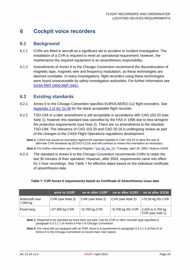
6.2.3 The standard in Annex 6 to the Chicago Convention recommends CVRs to retain the
last 30 minutes of their operation. However, after 2003, requirements came into effect
for 2 hour recordings. See Table 7 for effective dates based on the individual certificate
of airworthiness date.
Table 7: CVR Annex 6 requirements based on Certificate of Airworthiness issue date
prior to 1/1/87 on or after 1/1/87 on or after 1/1/03 on or after 1/1/16
Rotorcraft over 7,000 kg
CVR (see Note 2) CVR (see Note 2) CVR (see Note 2) >70,00 kg 2hr CVR
Fixed wing >27,000 kg CVR >5,700 kg CVR >5,700 kg 2hr CVR 2,250 to 5,700 kg CVR (see note 1)
Note 1: Required to be operated by more than one pilot. Can be CVR or other recorder type specified in
paragraph 6.3.2.1.1 of Annex 6 Part I of Chicago Convention.
Note 2: For rotorcraft not equipped with an FDR, there is a requirement in paragraph 4.3.2.1.3 of Part III of
Annex 6 to the Chicago Convention to record main rotor speed.
FLIGHT RECORDERS AND UNDERWATER
LOCATING DEVICES REQUIREMENTS
AC 21-24 v1.0 DRAFT April 2015 Page 25
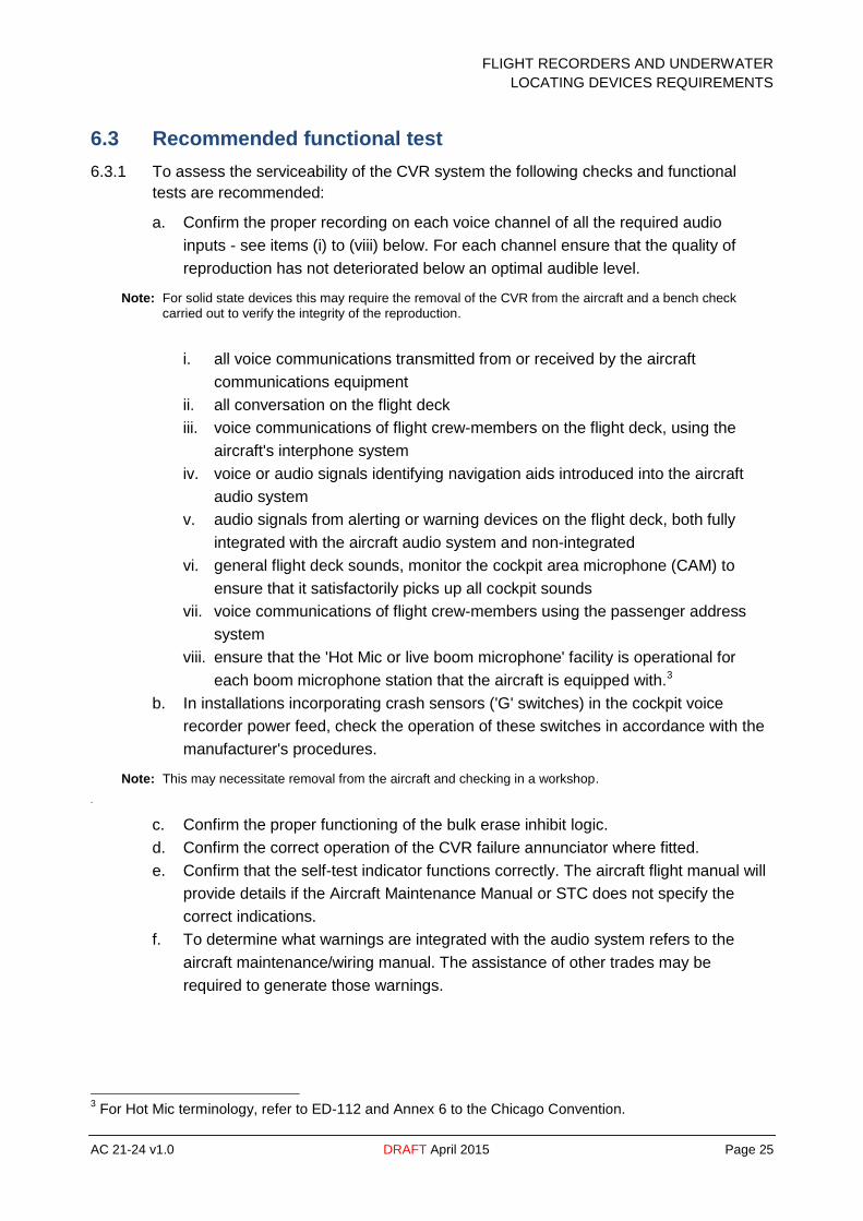
6.3 Recommended functional test
6.3.1 To assess the serviceability of the CVR system the following checks and functional
tests are recommended:
a. Confirm the proper recording on each voice channel of all the required audio
inputs - see items (i) to (viii) below. For each channel ensure that the quality of
reproduction has not deteriorated below an optimal audible level.
Note: For solid state devices this may require the removal of the CVR from the aircraft and a bench check
carried out to verify the integrity of the reproduction.
i. all voice communications transmitted from or received by the aircraft
communications equipment
ii. all conversation on the flight deck
iii. voice communications of flight crew-members on the flight deck, using the
aircraft's interphone system
iv. voice or audio signals identifying navigation aids introduced into the aircraft
audio system
v. audio signals from alerting or warning devices on the flight deck, both fully
integrated with the aircraft audio system and non-integrated
vi. general flight deck sounds, monitor the cockpit area microphone (CAM) to
ensure that it satisfactorily picks up all cockpit sounds
vii. voice communications of flight crew-members using the passenger address
system
viii. ensure that the 'Hot Mic or live boom microphone' facility is operational for
each boom microphone station that the aircraft is equipped with.3
b. In installations incorporating crash sensors ('G' switches) in the cockpit voice
recorder power feed, check the operation of these switches in accordance with the
manufacturer's procedures.
Note: This may necessitate removal from the aircraft and checking in a workshop.
.
c. Confirm the proper functioning of the bulk erase inhibit logic.
d. Confirm the correct operation of the CVR failure annunciator where fitted.
e. Confirm that the self-test indicator functions correctly. The aircraft flight manual will
provide details if the Aircraft Maintenance Manual or STC does not specify the
correct indications.
f. To determine what warnings are integrated with the audio system refers to the
aircraft maintenance/wiring manual. The assistance of other trades may be
required to generate those warnings.
3 For Hot Mic terminology, refer to ED-112 and Annex 6 to the Chicago Convention.
FLIGHT RECORDERS AND UNDERWATER
LOCATING DEVICES REQUIREMENTS
AC 21-24 v1.0 DRAFT April 2015 Page 26
6.4 Operators maintenance program
6.4.1 A maintenance program should be in place for the CVR. This program should be
reviewed on a regular basis, especially when:
a new aircraft type is added to the fleet
a change is made to flight recorder equipment
an operator's FDAP is introduced or modified (if applicable).
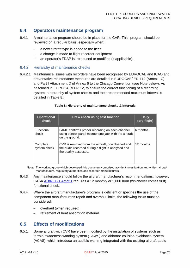
6.4.2 Hierarchy of maintenance checks
6.4.2.1 Maintenance issues with recorders have been recognised by EUROCAE and ICAO and
preventative maintenance measures are detailed in EUROCAE/ ED-112 (Annex I-C)
and Part I Attachment D of Annex 6 to the Chicago Convention (see Note below). As
described in EUROCAE/ED-112, to ensure the correct functioning of a recording
system, a hierarchy of system checks and their recommended maximum interval is
detailed in Table 8.:
Table 8: Hierarchy of maintenance checks & intervals
Operational check
Crew check using test function. Daily (pre-flight)
Functional check
LAME confirms proper recording on each channel using control panel microphone jack with the aircraft on the ground.
6 months
Complete system check
CVR is removed from the aircraft, downloaded and the audio recorded during a flight is analysed and the quality assessed.
12 months
Note: The working group which developed this document comprised accident investigation authorities, aircraft
manufacturers, regulatory authorities and recorder manufacturers.
6.4.3 Any maintenance should follow the aircraft manufacturer’s recommendations; however,
CASA AD/REC/1 Amdt 1 requires a 12 monthly or 2,000 hour (whichever comes first)
functional check.
6.4.4 Where the aircraft manufacturer’s program is deficient or specifies the use of the
component manufacturer’s repair and overhaul limits, the following tasks must be
considered:
overhaul (when required)
retirement of heat absorption material.
6.5 Effects of modifications
6.5.1 Some aircraft with CVR have been modified by the installation of systems such as
terrain awareness warning system (TAWS) and airborne collision avoidance system
(ACAS), which introduce an audible warning integrated with the existing aircraft audio
FLIGHT RECORDERS AND UNDERWATER
LOCATING DEVICES REQUIREMENTS
AC 21-24 v1.0 DRAFT April 2015 Page 27
system. When these modifications are made, suitable information about the introduced
audible warning should be added to the maintenance instructions for the aircraft audio
system. This information enables the audible warnings to be checked to ensure correct
recording on the CVR. Operators of such aircraft should ensure that suitable
maintenance information is available for the audible warning introduced by the
modification.
6.6 First of type/model CVR installation
6.6.1 As the ATSB has to be able to analyse the recorded data on the CVR in the event of an
incident or accident, a first of type/first of model installation must be validated as reliable
and the recording maintained to allow identification of various sounds in the cockpit. For
this reason the installation is test flown and the CVR sent to ATSB for analysis.
6.6.2 The flight check requirements are included in Appendix 1 of CAO 103.20; however, they
are reproduced in 7.4.1Appendix A of this AC for convenience.
FLIGHT RECORDERS AND UNDERWATER
LOCATING DEVICES REQUIREMENTS
AC 21-24 v1.0 DRAFT April 2015 Page 28
7 Underwater locating device
7.1 Background
7.1.1 As a result of accidents involving submerged aircraft and the failure of ULD, the United
States Of America National Transportation Safety Board (NTSB) issued a safety
recommendation that requires periodic testing of the beacon and batteries to ensure
their proper operation. Australia adopted this requirement as part of AD/REC/1.
7.1.2 Among other factors, the NTSB concluded that these acoustic ULDs were not tested in
accordance with manufacturer’s recommended procedures.
7.1.3 In one accident, the battery had been replaced but still failed to operate when
submerged underwater at the time of the accident. According to the maintenance
records, it was discovered that the operator had no program to routinely test in-service
acoustic ULD, nor did the operator perform any functional or off-current tests when the
batteries were replaced consistent with the manufacturers' requirements. Post-accident
testing revealed that the batteries discharged due to inadvertent activation induced by
metal filings around their water switch posts.
7.2 Existing standards
7.2.1 37.5 kHz operating frequency ULD
7.2.1.1 These devices are installed on flight recording equipment. The latest ULD standards
based on MPS of SAE 8045a are:
TSO-C121b
ETSO-C121b
7.2.1.2 Version b of the TSO standard extended the life of the ULD to 90 days, following of
catastrophic accident of Air France flight 447 in 2009.
7.2.1.3 A note in paragraph 2.5 of CAO 103.19 references FAA AC 21-10 as an acceptable
performance standard for ULDs; however current acceptable guidance is contained in
FAA AC 20-168.
7.2.2 8.8 kHz operating frequency ULD
7.2.2.1 The airframe low frequency ULD is intended to be mounted directly to the aircraft
airframe as a supplement to the existing ULDs, which are attached to the crash
protected recorders.
7.2.2.2 The latest ULD standards based on minimum performance standards of SAE AS 6254
are:
TSO-C200
ETSO-C200.
7.2.2.3 Amendment 36 in 2012 to Annex 6 to the Chicago Convention, states that a low
frequency ULD shall be installed on all aircraft with a maximum take-off mass of over
FLIGHT RECORDERS AND UNDERWATER
LOCATING DEVICES REQUIREMENTS
AC 21-24 v1.0 DRAFT April 2015 Page 29
27,000 kg, operating over water at particular distances to land suitable for making an
emergency landing. The installation of low frequency ULDs is undergoing review as part
of the changes to the CASA Flight Operations regulations development.
7.3 Maintenance program
7.3.1 An aircraft maintenance program is required to ensure that procedures for testing the
ULD, conducted concurrently with battery replacement, provide for functionally testing
the ULDs prior to replacing the old battery. This ensures that the ULD is still operating
properly.
7.3.2 The maintenance program should address the periodic maintenance of the ULD, such
as the:
periodic checking of the device operation in accordance with the manufacturers
requirements
life limits on the battery of the ULD
cleaning of the switch contacts.
7.3.3 CASA recommends ( an interval of):
90 days for an operational test and switch clean
battery replacement within the life limits of the battery.
Note: Some ULD do not have a replaceable battery. These units should be retired from service at the expiry of
the battery life limit.
7.4 Installation information
7.4.1 When installing the ULD on the flight recorder ensure that the switch contacts are
located in a manner that is not likely to encourage the build-up of debris that will cause
the contacts to short inadvertently. Either have the contacts vertical or facing down.
Executive Manager
Standards Division
April 2015

FLIGHT RECORDERS AND UNDERWATER
LOCATING DEVICES REQUIREMENTS
AC 21-24 v1.0 DRAFT April 2015 Page 30
Appendix A
Cockpit voice recorder flight test
FLIGHT RECORDERS AND UNDERWATER
LOCATING DEVICES REQUIREMENTS
AC 21-24 v1.0 DRAFT April 2015 Page 31
A.1 Introduction
A.1.1 First of type aircraft/recorder combinations must be flight tested and the recording,
obtained during that flight, must be analysed. The test and analysis must demonstrate
adequate recording quality during all normal regimes of flight including taxiing, take-off,
cruise, approach and landing. For helicopters, hover and auto-rotation should be
included.
A.1.2 Since the duration of the recording is limited, the CVR circuit breaker should be tripped
between each test phase and at the end of the landing run.
A.1.3 If time permits, systems that generate sounds on the flight deck, and might not
otherwise be used during the test flight, should be operated with appropriate
announcements.
A.1.4 This Appendix provides guidance for flight testing both aircraft and helicopters. It may
need to be adapted to suit the particular installation being tested.
A.1.5 The replay and analysis must be performed by the Technical Analysis section of the
ATSB. The Bureau will ensure the privacy of the recordings.
A.1.6 Recordings offered for analysis may be released to the operator’s engineering
organisation, the ATSB and CASA. The agreement of the flight crew concerned is
assumed unless instructions, in writing, are given by the flight crew stating any
restrictions to be applied.
A.2 Procedure
A.2.1 IMPORTANT: To enable proper analysis of the recording, it is essential that adequate
commentary on the flight is provided, e.g. crew actions altitudes and speed. Each test
should be clearly announced and the crew member identified, e.g. “Co-pilot testing -
oxygen mask microphone with interphone off”.
a. Prior to Engine Start
i. Check that the CVR is operating.
ii. Press the ERASE button.
iii. Press the CVR TEST button.
iv. Select BOOM microphone and interphone ‘ON’ at all positions.
v. Call out aircraft type, registration, date, time and crew complement.
b. Engine Start
i. (Helicopters only) During rotor spin-up, call out RPM at 50%, 80% and 100%.
ii. Make a test announcement from each crew member position in turn using the
boom microphones with interphone selected ‘ON’ followed by a second
announcement with the interphone ‘OFF’ (to evaluate the ‘hot’ microphone):
A. LEFT HAND SEAT POSITION
— INTERPHONE ON
"this is the Captain’s Position with boom microphone interphone on"
— INTERPHONE OFF
“this is the Captain’s Position with boom microphone interphone off”

FLIGHT RECORDERS AND UNDERWATER
LOCATING DEVICES REQUIREMENTS
AC 21-24 v1.0 DRAFT April 2015 Page 32
B. RIGHT HAND SEAT POSITION
— INTERPHONE ON
“this is the First Officer’s Position with boom microphone interphone on”
— INTERPHONE OFF
“this is the First Officer’s Position with boom microphone interphone off”
C. ENGINEER/THIRD CREW POSITION
— INTERPHONE ON
“this is the Engineer’s Position/third crew Position with boom microphone
interphone on'
— INTERPHONE OFF
'this is the Engineer’s Position/third crew Position with boom microphone
interphone off'
iii. Repeat steps A2.1 (b) (ii) using the oxygen mask microphone.
iv. (Aeroplanes only) Announce and test the stall warning stick shaker.
v. (Helicopters only) Close the flight deck windows.
c. Take-off
i. With headsets worn and boom microphones available for use, record a normal
take-off and initial climb.
ii. Announce landing gear and flap selections and other actions.
d. Cruise
i. With interphone OFF, announce and activate aural warnings.
ii. (Aeroplanes only) Accelerate to, and announce VMO. Continue until the
overspeed warning sounds. Reduce speed as required.
iii. Perform a test transmission from each pilot’s station using VHF and boom
microphones.
iv. Perform a test transmission from each pilot’s station using VHF, a hand-held
microphone and the flight deck loudspeakers (for response from ground
station).
v. Perform a test transmission from each pilot’s station using HF (if fitted) and
boom microphones.
vi. Perform a test transmission using the Marine radio if fitted.
vii. Perform test broadcasts from the flight deck and the cabin using the passenger
address system.
viii. (Helicopters only) Call out rotor RPM.
ix. Announce and open the flight deck cabin door. Announce and close the door
after 30 seconds.
x. Where permitted by the AFM and in cruise, announce and open the flight deck
windows. Announce and close the windows after 30 seconds.
xi. Select and identify navigation aids on each navigation set (this may be carried
out at any stage of the flight).
e. Helicopter Auto-Rotation and Hover
i. At a safe altitude, perform an auto-rotation descent with power recovery.
ii. Announce and hover for approximately one minute.

FLIGHT RECORDERS AND UNDERWATER
LOCATING DEVICES REQUIREMENTS
AC 21-24 v1.0 DRAFT April 2015 Page 33
f. Landing
i. Record final approach and landing including ILS and Marker audio
identification. Announce landing gear and flap selection and other actions.
ii. At end of landing run call out the time.
Note: check recording limitations
iii. Select BOOM microphone and interphone ‘ON’ at all positions and announce
'End of Test'.
g. DO NOT ERASE
h. PULL CVR CIRCUIT BREAKER.
A.3 Replay and analysis
A.3.1 The CVR should be sent to:
Attention: Team Leader Technical Analysis
ATSB
GPO Box 976
Civic Square ACT 2608
CANBERRA ACT 2601
Phone 1800 020 616 or 6257 4150 Fax 02 62743117.
A.3.2 A copy of the test schedule used during the flight should accompany the information
recorded from the CVR. In all cases, the manufacturer and model of the CVR and the
position of the area microphone in the particular aircraft should be stated in the
documentation supplied with the CVR recording.
A.3.3 ATSB will establish if recordings of adequate quality have been made on all channels
for the test conditions stated in 2.
A.3.4 ATSB will furnish a report to the operator, together with a copy to CASA. The report will
identify the aircraft and test flight concerned and will confirm that all input channels were
identified for the various test conditions. Details of any other observations made from
the recording will be included.
FLIGHT RECORDERS AND UNDERWATER
LOCATING DEVICES REQUIREMENTS
AC 21-24 v1.0 DRAFT April 2015 Page 34
Appendix B
Typical flight data recorder system check
procedures
FLIGHT RECORDERS AND UNDERWATER
LOCATING DEVICES REQUIREMENTS
AC 21-24 v1.0 DRAFT April 2015 Page 35
B.1 General
B.1.1 The operator should accomplish a reasonableness and quality check of the recorded
flight data to ascertain that the data is being recorded correctly, and that noise and data
dropouts do not interfere with the ability to interpret the recorded data. The check may
be performed using data that is in electronic format or using hard copy data. If a hard
copy printout is used, data traces should also be available.
B.1.2 The check should be performed using data that has been extracted in engineering
units. Octal, binary coded decimal, or hexadecimal coded data does not provide the
analyst a clear understanding of how the parameters are varying and how they are
correlated to each other. Particular attention should be paid to using the correct data
conversion algorithm appropriate to the aircraft recording system configuration.
B.1.3 It should be noted that the actual parameter fitment to an aircraft may be much more
comprehensive than required under the regulations and the structure of the check
should include a check of all parameters recorded.
B.2 Procedure/report
B.2.1 The analyst should use a checklist to ensure that all necessary checks have been
accomplished. The checklist should ensure the analyst accurately documents
inconsistencies in the data so that appropriate troubleshooting/repair procedures be
instigated.
B.2.2 The output of the reasonableness and quality process is a report that documents the
status of the aircraft recording system as a result of an Operational or Functional
Check.
B.3 Data analysis/flight segment selection
B.3.1 Parameter check
B.3.1.1 Failed Parameters: The analyst should examine the extracted data to determine if parameters that normally vary in flight do so within expected ranges, e.g. flight controls, flight control surface positions, and heading, are indeed varying. Pegged or unmoving parameter values are indications of an inoperative sensor or other failure. Accelerometers tend to fail in the 'pegged' position. If the accelerometer trace is unmoving throughout all segments of flight, check to see if it indicates maximum or minimum acceleration. An accelerometer failure indicating a mid-point value is uncommon.
B.3.1.2 Correlation to Other Parameters: The reasonableness check should include a check of
the correlation between parameters that depend upon each other.
For example:
If ROLL increases, a turn is indicated and HEADING should begin to change soon after the
increase is detected. Also, AILERON POSITION and CONTROL WHEEL POSITION should
have changed before the ROLL increase. One may even note a variation in LATERAL
ACCELERATION
FLIGHT RECORDERS AND UNDERWATER
LOCATING DEVICES REQUIREMENTS
AC 21-24 v1.0 DRAFT April 2015 Page 36
B.3.1.3 The data to be used by the analyst should be extracted from take-off, cruise and landing
phases of flight. The take-off and landing segments of flight provide the analyst an
opportunity to observe data that is changing as the aircraft climbs, descends,
accelerates, decelerates, and banks or turns. During the cruise segment of a flight most
parameters should remain reasonably steady. A lack of stability may reveal a fault in the
recording system.
B.3.1.4 Table 9 and
FLIGHT RECORDERS AND UNDERWATER
LOCATING DEVICES REQUIREMENTS
AC 21-24 v1.0 DRAFT April 2015 Page 37
B.3.1.5 Table 10 of this Appendix are samples provided as an aid in preparing a
reasonableness checklist. It summarises the mandatory parameters recorded in a 6-
parameter digital flight data recorder system and 20-parameter digital flight data
recorder system respectively. A check mark () in a block indicates that the parameter
identified in the row and the parameter identified in the column are interdependent at
some time during take-off and climb or approach and landing. Therefore, a change in
value of one parameter may cause or be caused by a change in the value of the other.
B.3.1.6 The following examples show how the tables may be used in developing a
reasonableness checklist for each parameter. Actual operation of the recorded
parameters may vary depending on the sensors installed and the aircraft systems that
are monitored.
B.3.2 A typical thrust reverser position reasonableness and quality check
In
FLIGHT RECORDERS AND UNDERWATER
LOCATING DEVICES REQUIREMENTS
AC 21-24 v1.0 DRAFT April 2015 Page 38
B.3.2.1 Table 10 the column labelled Thrust Reverser Position contains check marks in the
rows labelled airspeed, engine thrust, longitudinal acceleration and air/ground sensing.
In preparing the checklist, the operator would normally expect the thrust reverser to
deploy during rollout after landing. Therefore, the following checklist might be developed
using the parameters identified by a check mark:
Examine the thrust reverser in-transit and the thrust reverser deployed data to
determine that they indicate in-transit only for a short period during the landing roll
and deployed at the end of the in-transit period. Following touchdown, as indicated
by a change in the air/ground sensing discrete, the data should indicate a change
in the in-transit discrete followed by a change in the deployed/stowed discrete.
Examine the engine thrust data during the in-transit period and immediately after
the deployed indication. During the in-transit period, engine thrust should have
decreased to ground idle and immediately after the deployed indication, the engine
thrust should remain at ground idle or increase.
Examine the airspeed and longitudinal acceleration data. These two parameters
should be decreasing during the in-transit period and should dramatically decrease
immediately after the deployed indication as reverse thrust comes into effect.
Examine the engine thrust, thrust reverser deployed and thrust reverser in-transit
data to determine cancellation of reverse thrust. The engine thrust should remain at
ground idle or decrease to ground idle, the thrust reverser deployed/stowed and the
thrust reverser in transit discretes change state. Check that the discrete parameters
examined return to the values prior to landing.
Examine the remaining data for the thrust reverser discrete to ascertain that no in-
transit or deployed indications appear. If intermittent indications appear, determine
that they are within allowed values and do not have sufficient duration to be
interpreted as an actual deployment and that they would not obscure an actual
deployment.
B.3.3 Typical Lateral Control Surface Position Reasonableness and Quality Check
In

FLIGHT RECORDERS AND UNDERWATER
LOCATING DEVICES REQUIREMENTS
AC 21-24 v1.0 DRAFT April 2015 Page 39
B.3.3.1 Table 10 the column labelled lateral control surface position contains check marks in
the rows labelled heading, roll attitude and lateral control position. The lateral control
surfaces are typically ailerons that are used in establishing the aircraft in a turn and
returning the aircraft to straight flight from a turn. The lateral control surface position
data may be checked along with the lateral control position data. These checks may be
accomplished during the approach and landing segment.
Examine the lateral control surface position trace for deviations during the initial
approach segment. A large sustained deviation would normally indicate the aircraft
turning onto final approach heading. Check that the lateral control position and roll
attitude make a large change at the same time.
Check to determine that heading begins to change immediately after the lateral
control surface position begins to change. Heading should continue to change after
the lateral control surface position returns to the zero or null value. The heading
data should begin to change at a lower rate when the lateral control surface
position data moves in the opposite direction and after the lateral control position is
again returned to zero or null the heading data should again be constant.
B.3.3.2 Check the lateral control surface position data to determine that there are no data
dropouts and that there is no noise in the data. If dropouts or noise are detected,
determine that they are within allowable values and that they would not be interpreted
as an actual control surface position movement.
Table 9: 6-parameter correlation
Num
ber
Para
met
er
Tim
e
Pres
sure
Alt
itud
e
Indi
cate
d A
irsp
eed
Hea
ding
Ver
tica
l acc
eler
atio
n
Pres
s to
tran
smit
1 Time
2 Pressure Altitude
3 Indicated Airspeed
4 Heading
5 Vertical acceleration
6 Press to transmit
Note: The parameters are numbered as per Appendix 1 of CAO 103.19

FLIGHT RECORDERS AND UNDERWATER
LOCATING DEVICES REQUIREMENTS
AC 21-24 v1.0 DRAFT April 2015 Page 40
Table 10: 20-parameter correlation
Note: The parameters are numbered as per Appendix 1 of CAO 103.19
Tim
e
Alt
itud
e
Air
spee
d
Hea
ding
Ver
tica
l Acc
eler
atio
n
Pitc
h A
ttit
ude
Rol
l Att
itud
e
Pres
s to
tra
nsm
it fo
r ea
ch t
rans
ceiv
er
Thru
st o
f ea
ch e
ngin
e
Long
itud
inal
Acc
eler
atio
n
Pitc
h C
ontr
ol P
osit
ion
Late
ral C
ontr
ol P
osit
ion
Yaw
Con
trol
Pos
itio
n
Pitc
h C
ontr
ol S
urfa
ce P
osit
ion
Late
ral C
ontr
ol S
urfa
ce P
osit
ion
Yaw
Con
rol S
urfa
ce P
osit
ion
Late
ral A
ccel
erat
ion
Pitc
h tr
im s
urfa
ce p
osit
ion
Trai
ling
edge
Fla
ps S
lats
Lead
ing
edge
Fla
ps S
lats
Thru
st R
ever
se p
osit
ion
Und
erca
rria
ge s
quat
or
tilt
sw
itch
Ang
le o
f at
tack
1 Time
2 Altitude
3 Airspeed
5 Heading
4 Vertical Acceleration
7 Pitch Attitude
8 Roll Attitude
6 Press to transmit for each transceiver
9 Thrust of each engine
11 Longitudinal Acceleration
18 Pitch Control Position
19 Roll Control Position
20 Yaw Control Position
18 Pitch Control Position
19 Roll Control Position
20 Yaw Control Position
16 Lateral Acceleration
17 Pitch Trim
10 Trailing edge Flaps
14 Leading edge Devices stowed/deployed
13 Thrust Reverser stowed/deployed (each engine)
12 Undercarriage squat or tilt switch
15 Angle of attack