dr. n.n.c.e mech/ vi sem te lab ii - lm ii lab manual.pdf · dr. n.n.c.e mech/ vi sem te lab ii -...
TRANSCRIPT
Dr. N.N.C.E MECH/ VI Sem TE LAB II - LM
1
ME2355-THERMAL ENGINEERING LABORATORY II
LABORATORY MANUAL
FOR SIXTH SEMESTER MECHANICAL ENGG.
(FOR PRIVATE CIRCULATION ONLY)
ACADEMIC YEAR 2013 – 2014(EVEN)
ANNA UNIVERSITY CHENNAI
DEPARTMENT MECHANICAL ENGINEERING
Dr. NAVALAR NEDUNCHEZHIYAN COLLEGE OF ENGINEERING
THOLUDUR – 606 303, CUDDALORE DIST.,
Dr. N.N.C.E MECH/ VI Sem TE LAB II - LM
2
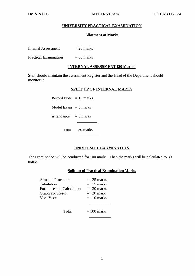
UNIVERSITY PRACTICAL EXAMINATION
Allotment of Marks
Internal Assessment = 20 marks Practical Examination = 80 marks
INTERNAL ASSESSMENT [20 Marks]
Staff should maintain the assessment Register and the Head of the Department should monitor it.
SPLIT UP OF INTERNAL MARKS
Record Note = 10 marks Model Exam = 5 marks Attendance = 5 marks __________ Total 20 marks ___________
UNIVERSITY EXAMINATION
The examination will be conducted for 100 marks. Then the marks will be calculated to 80 marks.
Split up of Practical Examination Marks Aim and Procedure = 25 marks Tabulation = 15 marks Formulae and Calculation = 30 marks Graph and Result = 20 marks Viva Voce = 10 marks ___________ Total = 100 marks ___________
Dr. N.N.C.E MECH/ VI Sem TE LAB II - LM
3
GENERAL INSTRUCTIONS FOR LABORATORY CLASSES
• Enter the Lab with CLOSED FOOTWEAR.
• Boys should “TUCK IN” the shirts.
• Students should wear uniform only .
• LONG HAIR should be protected, let it not be loose especially near ROTATING
MACHINERY.
• Any other machines / equipments should not be operated other than the prescribed
one for that day.
• POWER SUPPLY to your test table should be obtained only through the LAB
TECHNICIAN.
• Do not LEAN and do not be CLOSE to the rotating components.
• TOOLS, APPARATUS and GUAGE sets are to be returned before leaving the lab.
• HEADINGS and DETAILS should be neatly written
i. Aim of the experiment
ii. Apparatus / Tools / Instruments required
iii. Procedure / Theory / Algorithm / Program
iv. Model Calculations
v. Neat Diagram / Flow charts
vi. Specifications / Designs Details
vii. Tabulations
viii. Graph
ix. Result / discussions.
• Before doing the experiment, the student should get the Circuit / Program approval by
the FACULTY-IN-CHARGE.
• Experiment date should be written in the appropriate place.
• After completing the experiment, the answer to the viva-voce questions should be
neatly written in the work book.
• Be PATIENT, STEADY, SYSTEMATIC AND REGULAR.

Dr. N.N.C.E MECH/ VI Sem TE LAB II - LM
4
LIST OF EXPERIMENTS
HEAT TRANSFER
1. Thermal conductivity measurement by guarded plate method.
2. Thermal conductivity of pipe insulation using lagged pipe apparatus.
3. Natural convection heat transfer from a vertical cylinder.
4. Forced convection inside tube.
5. Heat transfer from pin-fin(natural & forced convection modes)
6. Determination of Stefan-Boltzmann constant.
7. Determination of emissivity of a gray surface.
8. Effectiveness of Parallel/counter flow heat exchanger.
REFRIGERATION AND AIR CONDITIONING
1. Determination of COP of a refrigeration system.
2. Experiments on air-conditioning system.
3. Performance test on single/two stage reciprocating air compressor.
LIST OF EXPERIMENTS BEYOND THE SYLLUBUS
1. Thermal Conductivity of insulating powder.
2. Thermal Conductivity of metal rod.
3. Calorific value determination by Junker’s gas calorimeter.
Dr. N.N.C.E MECH/ VI Sem TE LAB II - LM
5
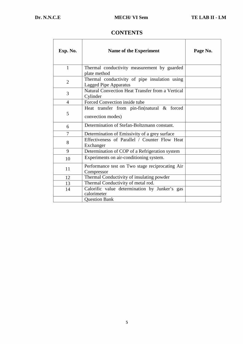
CONTENTS
Exp. No.
Name of the Experiment Page No.
1
Thermal conductivity measurement by guarded plate method
2 Thermal conductivity of pipe insulation using Lagged Pipe Apparatus
3 Natural Convection Heat Transfer from a Vertical Cylinder
4 Forced Convection inside tube
5 Heat transfer from pin-fin(natural & forced
convection modes)
6 Determination of Stefan-Boltzmann constant.
7 Determination of Emissivity of a grey surface
8 Effectiveness of Parallel / Counter Flow Heat Exchanger
9 Determination of COP of a Refrigeration system
10 Experiments on air-conditioning system.
11 Performance test on Two stage reciprocating Air Compressor
12 Thermal Conductivity of insulating powder 13 Thermal Conductivity of metal rod. 14 Calorific value determination by Junker’s gas
calorimeter
Question Bank

Dr. N.N.C.E MECH/ VI Sem TE LAB II - LM
6
OBSERVATION:
MINIMUM 40 VOLTS [BOTH]
S.
No. Volts Amps Volts Amps T1 T2 T3 T4 T5 T6 T7 T8 T9
1.
2.
3.
39
36
32
0.18
0.16
0.14
44.1
41
36
0.14
0.13
0.12
34.2
22.6
23.8
32.3
34.5
35.0
41.3
44.4
44.5
80.9
85.0
82.5
62.5
66.4
65.4
92.1
95.6
92.0
98.4
102.8
98.7
42.0
44.9
45.0
34.6
37.4
38.2
CALCULATION:
Insulating material : Asbestos sheet [commercial grade] Specimen diameter = 150 mm = 0.15 m. Area of specimen = π / 4 x [0.15]2 = 0.018 m2. Specimen thickness = ∆ L = 12 mm = 0.012 m. Volts = 32 Amps = 0.14 Main heater Volts = 36 Amps = 0.12 Ring heater Heat input q = q [main heater] + q [guard heater] = [32 x 0.14 x 0.86] + [36 x 0.12 x 0.86] = 3.85 + 3.71 = 7.56 kcal/hr. It should be noted that out of this heat input, ideally only a half will pass through each of the specimens [top and bottom]. Hence q = q / 2 = 7.56 / 2 = 3.78 kcal/hr. ∆ T = {[T4 – T3] + [T7 – T8]} / 2 = {[82.5 – 44.5] + [98.7 – 45.0]} / 2 = [38 + 53.7] / 2 = 91.7 / 2 = 45.850C. Thermal conductivity of specimen K = q ∆L / A ∆T = 3.78 x 0.012 / 0.018 x 45.85 = 0.04536 / 0.8253 = 0.05496 kcal/hr m0C.
Dr. N.N.C.E MECH/ VI Sem TE LAB II - LM
7
Experiment Number: 1 Title of the Experiment: Thermal Conductivity Measurement By Guarded
Plate Method
Date of the Experiment:
OBJECTIVE [AIM] OF THE EXPERIMENT
To determine the thermal conductivity of a poor conducting material, say Asbestos sheet.
RELEVANT THEORY Thermal conductivity is a specific property of conducting material which is defined below for a homogeneous solid as the quantity of heat conducted across a unit area normal to the flow direction in unit time and for unit temperature gradient along the flow. K = q dL / A dT Where, q = heat conducted in watts dL = thickness [m] A = Area of conduction heat transfer, m2 dT = temperature difference across the length dL [0C]
MEASUREMENT:
Experimental measurement of thermal conductivities of solids can be accomplished by a variety of methods, all based on the observation of the temperature gradient across a given area of the material conducting heat at a known rate. Each of these methods has certain unique limitations, and the choice of one over another is governed by the general temperature level at which K is measured, by the physical structure of the material in question and by whether the material is a good or poor conductor.
In measuring the thermal conductivity of poor conductors, the specimens are taken in the form of sheets in order that the heat flow path is short and the conducting area large. [low dL, higher A].
Dr. N.N.C.E MECH/ VI Sem TE LAB II - LM
8
FACILITIES REQUIRED AND PROCEDURE
a] Facilities required to do the experiment:
Sl. No.
Facilities required
Quantity
1.
Guarded plate apparatus
1
SPECIFICATIONS:
Material = Asbestos sheet [commercial grade] Specimen diameter [d] = 150 mm or 0.15 m. Specimen thickness dL = 12 mm or 0.012 m. Area of specimen = π / 4 x [0.15]2 m2 Heat input = VI watts [q]
b] Guarded Hot Plate method [Solids] The apparatus consists of a Guarded Hot Plate, the arrangement along with thermocouple positions [T3, T4] across the specimen and T5, T6 guarded heater temperature [only for check] [T1, T2] Top and Bottom pad temperatures.
The panel consists of voltmeter, ammeter, temperature indicator [all digital], dimmer controls, voltmeter and ammeter selector [common switch, thermocouple selector switch].
c] Operation: a] Connect the three pin plug top to 230 V, 50 Hz, 5 Amps power supply socket, dimmers in OFF position. b] Keep the voltmeter and ammeter switch in 1 position. Turn the dimmer in clockwise and adjust the power input to main heater to any desired value by looking at voltmeter and ammeter. c] Turn the voltmeter and ammeter switch to position marked 2 and check the voltage & current are same for ring heater. d] Allow the unit to stabilize [approx 30 minutes].
e] Note down the temperature indicated by the digital temperature indicator by turning the thermocouple selector switch clockwise step by step [1, 2, 3, 4, 5, and 6].
f] Repeat the experiment for different power inputs to the heater. g] Tabulate all the readings and calculate for different conditions. h] After the experiment is over turn all the dimmer knobs anti clockwise, direction to zero. i] Disconnect the three pin plug top from the mains.

Dr. N.N.C.E MECH/ VI Sem TE LAB II - LM
9
CAUTION:
The equipment should be operated between 0 and 150 V.
d] Procedure for doing the experiment:
Step No. Details of the Step
1. Supply a small quantity of energy to the source ‘H’ [the main heater MH].
2. Now adjust the input to the guard heaters such that the temperature is same
as that of the main heater
3. Allow water through the cooling circuit slowly.
4. Allow 30 – 60 minutes for the temperatures to stabilize.
5. Note down all the parameter
6. Repeat the experiment at different temperature values by adjusting
appropriately the input conditions.
e] Result:
Thus the thermal conductivity of a poor conducting material [Asbestos sheet] is determined. K= 0.05496 Kcal / hr m0C.
Dr. N.N.C.E MECH/ VI Sem TE LAB II - LM
10
VIVA QUESTIONS
1. Define heat transfer.
Heat transfer can be defined as the transmission of energy from one region to
another due to temperature difference.
2. What are the modes of heat transfer?
1. Conduction
2. Convection
3. Radiation.
3. What is conduction?
Heat conduction is a mechanism of heat transfer from a region of high temperature to
a region of low temperature within a medium [solid, liquid or gases] or different
medium in direct physical contact.
4. State Fourier’s law of conduction.
The rate of heat conduction is proportional to the area measured normal to the
direction of heat flow and to the temperature gradient in that direction.
Q α – A dT / dx
Q = -kA dT /dx
Where, A – Area in m2.
dT / dx – Temperature gradient, K/m
k – Thermal conductivity, W/mK.
5. Define Thermal conductivity.
Thermal conductivity is defined as the ability of a substance to conduct heat.

Dr. N.N.C.E MECH/ VI Sem TE LAB II - LM
11
Experiment Number: 2 Title of the Experiment: Thermal Conductivity Of Pipe Insulation Using
Lagged Pipe Apparatus Date of the Experiment:
OBJECTIVE [AIM] OF THE EXPERIMENT:
To plot the radial temperature distribution in the composite cylinder and to determine the thermal conductivity of the pipe insulation.
THEORY
Consider one dimensional radial heat flow through a hollow cylinder, under steady state conditions. q = 2πKL [T 1 – T2] / ln [r2/r1] Where T1, T2 are the inner and outer wall temperature r1 and r2 are the inner and outer radii of the pipe. K = Thermal conductivity of the material. FACILITIES REQUIRED AND PROCEDURE
a] Facilities required to do the experiment:
Sl. No.
Facilities required
Quantity
1.
Lagged Pipe Apparatus
1
b] Description of the Apparatus:
The apparatus consists of a metal pipe with two layers of insulation. An electric heating coil wound on a silica rod is placed at the center. The ends are thickly insulated to prevent heat loss so that, heat flow only in a radial direction. Three thermocouples each are placed at different radii to measure the temperature distribution within the cylinder. c] Technical Data:
Location of thermocouples 1, 2, 3 at a radius = 25 mm. Location of thermocouples 4, 5, 6 at a radius = 37.5 mm. Location of thermocouples 7, 8, 9 at a radius = 50 mm. Location of thermocouples 10, 11, 12 at a radius = 62.5 mm. Length of the pipe L = 500 mm.
TABULATION

Dr. N.N.C.E MECH/ VI Sem TE LAB II - LM
12
S.No
Heat Input
[watts]
Temp at Radius
R1 0C
Temp at Radius
R2 0C
Temp at Radius
R3 0C
Temp at Radius
R4 0C
1.
V A q T1 T2 T3 T4 T5 T6 T7 T8 T9 T10 T11 T12
75
0.44
33
111.8
133.8
102.2
37.2
41.9
37.3
35.4
39.9
39.7
31.8
30.2
30.4
MODEL CALCULATION:
At r1 = 25 mm T1 = (111.8 + 133.8 + 102.2) / 3 = 115.930C.
At r2 = 37.5 mm T2 = (37.2 + 41.9 + 37.3) / 3 = 38.80C. At r3 = 50 mm T3 = (35.4 + 39.9 + 39.7) / 3 = 38.330C. At r4 = 62.5 mm T4 = (31.8 + 30.2 + 30.4) / 3 = 30.80C. q = 2 π KL [T2 – T3] / ln [r3/r2] q = V x I = 75 x 0.44 = 33. K = q ln [r3/r2] / 2π L [T2 – T3] = 33 ln [0.05/0.0375] / 2π x 0.5 [38.8 – 38.33] K = 0.1948 W/mK.

Dr. N.N.C.E MECH/ VI Sem TE LAB II - LM
13
d] Procedure for doing the experiment:
Step No. Details of the Step
1. Connect the equipment to a 230V, 5 amps, and 50 HZ electrical source. 2. Twin the dimmerstat knob clockwise and fix the heat input to a desired
wattage [V x I] 3. Allow the equipment to stabilize and attain steady state. 4. Turn the thermocouple selector switch knob clockwise and note down
temperature T1 to T12. 5. Repeat the experiment for different heat inputs.
d] Formula: q = 2 π KL [T2 – T3] / ln [r3/r2]
T2 = Temperature at radius r2 0 C
T3 = Temperature at radius r3 0C r = radius of the pipe ‘m’ K = Thermal Conductivity – W/m K L = Length of the pipe – ‘m’ e] Result: Thus the thermal Conductivity of the pipe insulation is determined.
K = 0.1948 W/m K.
Dr. N.N.C.E MECH/ VI Sem TE LAB II - LM
14
VIVA QUESTIONS
1. What is conduction? Heat conduction is a mechanism of heat transfer from a region of high temperature to a region of low temperature within a medium [solid, liquid or gases] or different medium in direct physical contact.
2. State Fourier’s law of conduction. The rate of heat conduction is proportional to the area measured normal to the
direction of heat flow and to the temperature gradient in that direction. Q α – A dT / dx Q = -kA dT /dx Where, A – Area in m2. dT / dx – Temperature gradient, K/m k – Thermal conductivity, W/mK.
3. Define Thermal conductivity. Thermal conductivity is defined as the ability of a substance to conduct heat.
4. Write down the equation for conduction of heat through a slab or plane wall. Heat transfer, Q = ∆ Toverall / R Where, ∆ T = T1 – T2 R = L / kA – Thermal resistance of slab L – Thickness of slab K – Thermal conductivity of slab A – Area
5. Write down the equation for conduction of heat through a hollow cylinder. Heat transfer, Q = ∆ Toverall / R Where ∆ T = T1 – T2 R = 1 / 2πLk in [r2 / r1] – Thermal resistance of slab. L – Length of cylinder k – Thermal conductivity r2 – Outer radius r1 – Inner radius
6. What are the factors affecting the thermal conductivity? a. Moisture b. Density of material c. Pressure d. Temperature e. Structure of material.
Dr. N.N.C.E MECH/ VI Sem TE LAB II - LM
15
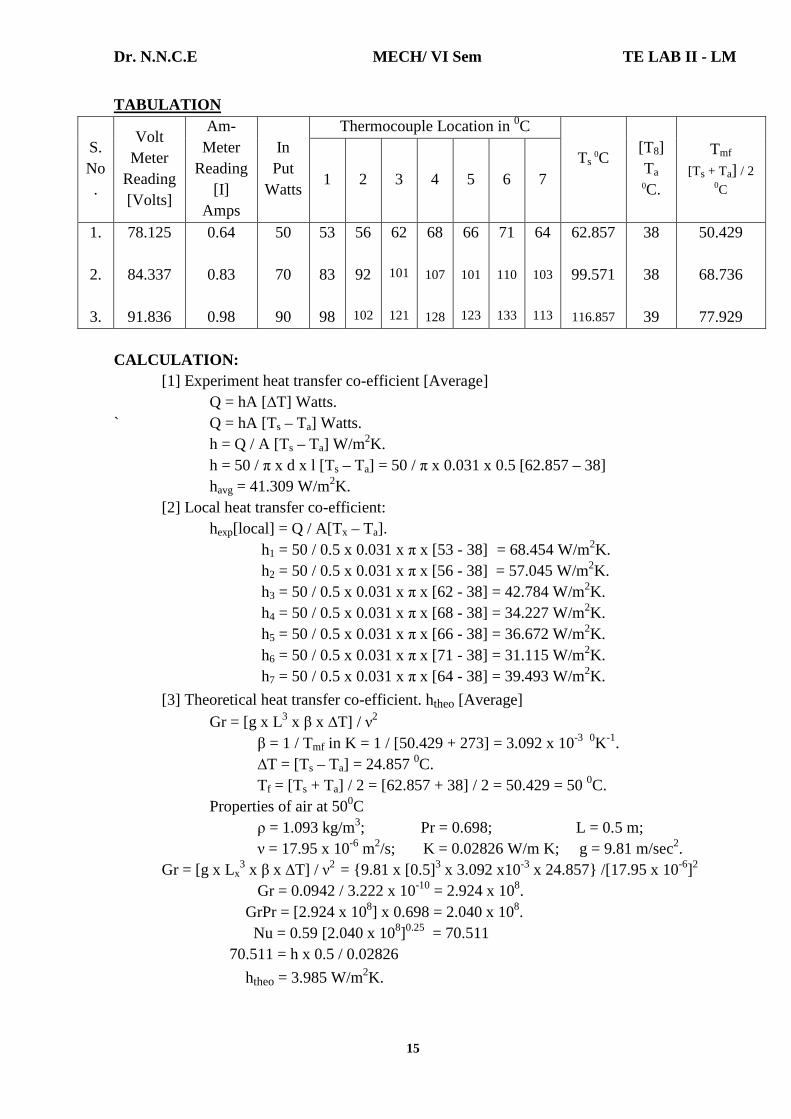
TABULATION
S. No.
Volt Meter
Reading [Volts]
Am- Meter
Reading [I]
Amps
In Put
Watts
Thermocouple Location in 0C
Ts 0C
[T8] Ta 0C.
Tmf [Ts + Ta] / 2
0C 1 2 3 4 5 6 7
1.
2.
3.
78.125
84.337
91.836
0.64
0.83
0.98
50
70
90
53
83
98
56
92
102
62
101
121
68
107
128
66
101
123
71
110
133
64
103
113
62.857
99.571
116.857
38
38
39
50.429
68.736
77.929
CALCULATION: [1] Experiment heat transfer co-efficient [Average]
Q = hA [∆T] Watts. ` Q = hA [Ts – Ta] Watts. h = Q / A [Ts – Ta] W/m2K. h = 50 / π x d x l [Ts – Ta] = 50 / π x 0.031 x 0.5 [62.857 – 38] havg = 41.309 W/m2K.
[2] Local heat transfer co-efficient: hexp[local] = Q / A[Tx – Ta]. h1 = 50 / 0.5 x 0.031 x π x [53 - 38] = 68.454 W/m2K. h2 = 50 / 0.5 x 0.031 x π x [56 - 38] = 57.045 W/m2K. h3 = 50 / 0.5 x 0.031 x π x [62 - 38] = 42.784 W/m2K. h4 = 50 / 0.5 x 0.031 x π x [68 - 38] = 34.227 W/m2K. h5 = 50 / 0.5 x 0.031 x π x [66 - 38] = 36.672 W/m2K. h6 = 50 / 0.5 x 0.031 x π x [71 - 38] = 31.115 W/m2K. h7 = 50 / 0.5 x 0.031 x π x [64 - 38] = 39.493 W/m2K.
[3] Theoretical heat transfer co-efficient. htheo [Average] Gr = [g x L3 x β x ∆T] / ν2
β = 1 / Tmf in K = 1 / [50.429 + 273] = 3.092 x 10⁻³ 0K-1. ∆T = [Ts – Ta] = 24.857 0C. Tf = [Ts + Ta] / 2 = [62.857 + 38] / 2 = 50.429 = 50 0C. Properties of air at 500C ρ = 1.093 kg/m3; Pr = 0.698; L = 0.5 m; ν = 17.95 x 10⁻⁶ m2/s; K = 0.02826 W/m K; g = 9.81 m/sec2. Gr = [g x Lx
3 x β x ∆T] / ν2 = {9.81 x [0.5]3 x 3.092 x10-3 x 24.857} /[17.95 x 10-6]2 Gr = 0.0942 / 3.222 x 10-10 = 2.924 x 10⁸. GrPr = [2.924 x 108] x 0.698 = 2.040 x 10⁸. Nu = 0.59 [2.040 x 10⁸]0.25 = 70.511
70.511 = h x 0.5 / 0.02826
htheo = 3.985 W/m2K.
Dr. N.N.C.E MECH/ VI Sem TE LAB II - LM
16
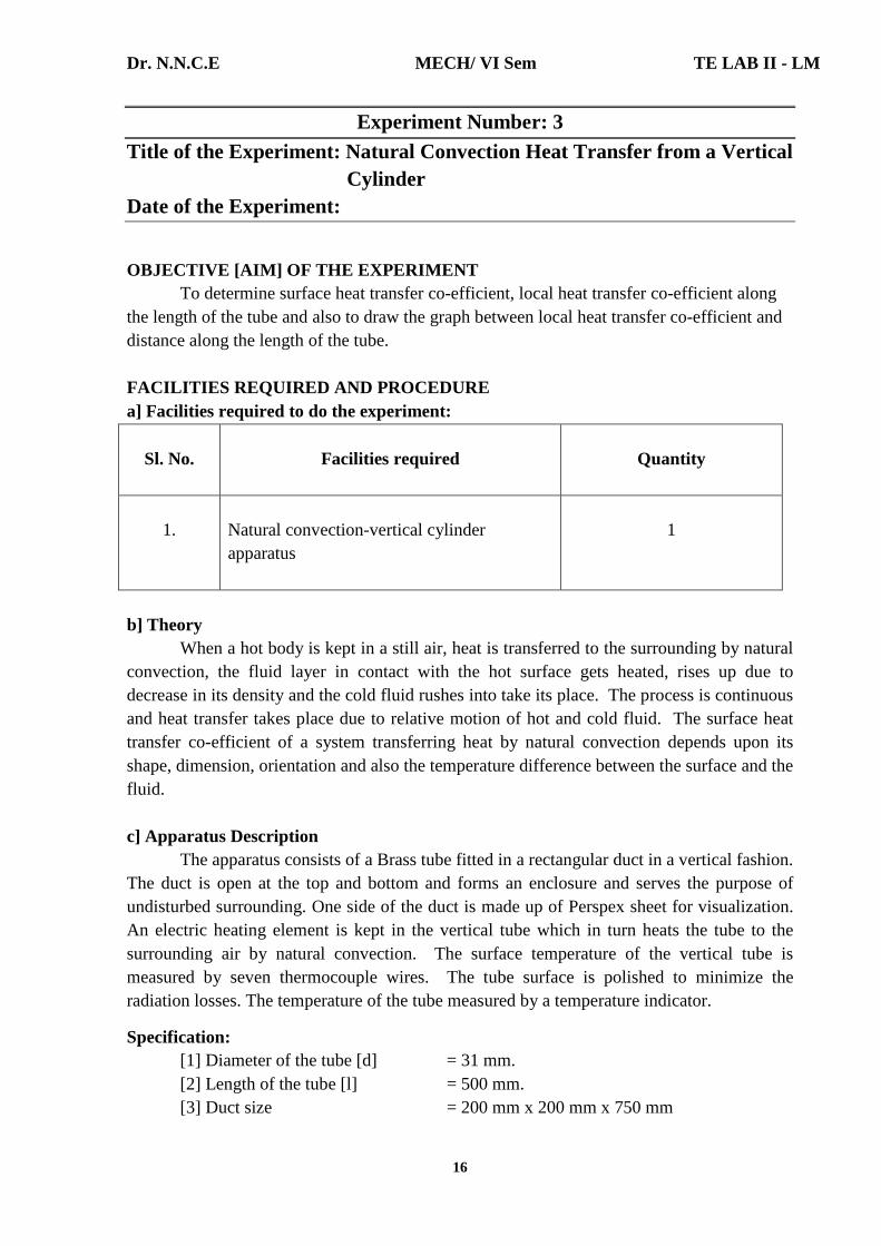
Experiment Number: 3 Title of the Experiment: Natural Convection Heat Transfer from a Vertical
Cylinder Date of the Experiment:
OBJECTIVE [AIM] OF THE EXPERIMENT To determine surface heat transfer co-efficient, local heat transfer co-efficient along the length of the tube and also to draw the graph between local heat transfer co-efficient and distance along the length of the tube. FACILITIES REQUIRED AND PROCEDURE a] Facilities required to do the experiment:
Sl. No.
Facilities required
Quantity
1.
Natural convection-vertical cylinder apparatus
1
b] Theory When a hot body is kept in a still air, heat is transferred to the surrounding by natural convection, the fluid layer in contact with the hot surface gets heated, rises up due to decrease in its density and the cold fluid rushes into take its place. The process is continuous and heat transfer takes place due to relative motion of hot and cold fluid. The surface heat transfer co-efficient of a system transferring heat by natural convection depends upon its shape, dimension, orientation and also the temperature difference between the surface and the fluid. c] Apparatus Description The apparatus consists of a Brass tube fitted in a rectangular duct in a vertical fashion. The duct is open at the top and bottom and forms an enclosure and serves the purpose of undisturbed surrounding. One side of the duct is made up of Perspex sheet for visualization. An electric heating element is kept in the vertical tube which in turn heats the tube to the surrounding air by natural convection. The surface temperature of the vertical tube is measured by seven thermocouple wires. The tube surface is polished to minimize the radiation losses. The temperature of the tube measured by a temperature indicator.
Specification: [1] Diameter of the tube [d] = 31 mm. [2] Length of the tube [l] = 500 mm. [3] Duct size = 200 mm x 200 mm x 750 mm

Dr. N.N.C.E MECH/ VI Sem TE LAB II - LM
17
[4] Theoretical Local heat transfer co-efficient. htheo [Local] Gr [local] = [g x β x Lx
3 x ∆T] / ν2 [i] Tmf [Local] = [Tx + Ta] / 2 = [53 +38] / 2 = 45.50C. Properties of air at 45.50C ρ = 1.109 kg/m3; Pr = 0.685; Lx = 0.01 m; ν = 17.505 x 10⁻⁶ m2/s K = 0.02795 W/mK; g = 9.81 m2/s; Gr = [g x β x Lx
3 x ∆T] / ν2 β = 1 / 318.5 = 3.140 x 10⁻³. = 9.81 x 3.140 x 10-3 x 0.013 x [53 – 38] / [17.505 x 10⁻⁶]2 Gr = 1.508 x 10³. Gr Pr = [1.508 x 10³] [0.685] Gr Pr = 1.033 x 10³. 104 ≤ Gr Pr ≤ 109 Nu = [0.59] [Gr Pr] 0.25 = [0.59] [1.033 x 10³] 0.25 = 3.345 Nu = hL Lx / K 3.345 = hL [0.01] / 0.02795
hL1 = 9.349 W/m2K. [ii] T mf [Local] = [Tx + Ta] / 2 = [56 + 38] / 2 = 470C.
Properties of air at 470C ρ = 1.104 kg/m3; Pr = 0.689; Lx = 0.05 m; ν = 17.653 x 10⁻⁶ m2/s K = 0.02805 W/mK; β = 1 /320 = 3.125 x 10⁻³
Gr = [g x β x Lx3 x ∆T] / ν2
= 9.81 x 3.125 x 10-3 x 0.053 x [56 - 38] / [17.653 x 10⁻⁶]2
Gr = 2.214 x 10⁵. Gr Pr = [2.214 x 105] x [0.689] = 1.525 x 10⁵ Nu = [0.59] [1.525 x 10⁵]0.25 = 11.66. Nu = hL Lx / K 11.66 = [hL x 0.05] / 0.02805
hL2 = 6.54 W/m2K. [iii] T mf = [Tx + Ta] / 2 = [62 + 38] / 2 = 500C.
Properties of air at 500C ρ = 1.093 kg/m3; Pr = 0.698; Lx = 0.1 m; ν = 17.95 x 10⁻⁶ m2/s K = 0.02826 W/mK; β = 3.0296 x 10⁻³
Gr = g x β x Lx3 x ∆T / ν2
Gr = 9.81 x 3.096 x 10-3 x 0.13 x [62 - 38]/ [17.95 x 10⁻⁶]2 = 2.262 x 10⁶. Gr Pr = [2.262 x 106] x [0.698] = 1.579 x 10⁶. Nu = [0.59] [1.579 x 10⁶]0.25 = 20.91. Nu = hL Lx / K 20.91 = [hL x 0.1] / 0.02826
hL3 = 5.909 W/m2K. [iv] T mf = [Tx + Ta] / 2 = [68 + 38] / 2 = 530C.
Properties of air at 530C ρ = 1.083 kg/m3; Pr = 0.697; Lx = 0.2 m;
ν = 18.26 x 10⁻⁶ m2/s K = 0.02847 W/mK; β = 3.067 x 10⁻³

Dr. N.N.C.E MECH/ VI Sem TE LAB II - LM
18
[4] Number of Thermocouples = 7 and are shown as [1] – [7] and as marked on temperature indicator switch.
[5] Thermocouple number 8 reads the temperature of the air in the duct. [6] Temperature indicator 0 – 3000C. Multichannel type, calibrated for chromel – alumel thermo couples. [7] Ammeter = [0 – 2A] [8] Voltmeter = [0 – 100/200V] [9] Dimmer start = 2A/230Volt. [10] Heater – cartridge type = 400 Watts
d] Procedure for doing the experiment:
Step No. Details of the Step
1. Switch on the supply and adjust the dimmerstat to obtain the required heat
input.
2. Wait till the fairly steady state is reached, which is confirmed from
temperature readings [T1 to T7].
3. Note down surface temperature at various points.
4. Note the Ambient Temperature [T8].
5. Repeat the experiment at different heat inputs.
Precautions:
[1] Do not exceed 100 Watts. [2] Operate the change over selector switch gently from position [1] to [8].
Formula Used: [1] Ts = [T1 + T2 + T3 + T4 + T5 + T6 + T7] / 7 0C Where T1, T2, T3,………..T7 are temperature at locations 1, 2 --7 Mean film temperature [Tmf] = [Ts + Ta] / 2.
Where Ts = Average surface temperature in 0C. Ta = Ambient Temperature in 0C. Experiment heat transfer co-efficient [Average] Q = hA [∆T] Watts. Where h = Experimental convective heat transfer co-efficient [Average] W/m2K. A = Area of heat transfer πd L m2. ∆T = Ts – Ta in 0C. Ts = Surface temperature in 0C. Ta = Ambient temperature in 0C. Q = Average rate of heat transfer by convection in [Watts]. hexp [average] = Q / As[Ts – Ta] W/m2K.
Dr. N.N.C.E MECH/ VI Sem TE LAB II - LM
19
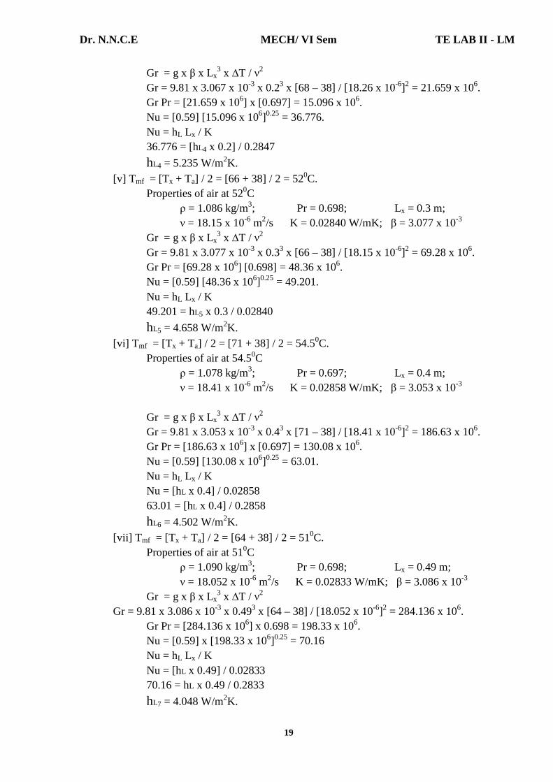
Gr = g x β x Lx3 x ∆T / ν2
Gr = 9.81 x 3.067 x 10-3 x 0.23 x [68 – 38] / [18.26 x 10⁻⁶]2 = 21.659 x 10⁶. Gr Pr = [21.659 x 106] x [0.697] = 15.096 x 10⁶. Nu = [0.59] [15.096 x 10⁶]0.25 = 36.776. Nu = hL Lx / K 36.776 = [hL4 x 0.2] / 0.2847
hL4 = 5.235 W/m2K.
[v] Tmf = [Tx + Ta] / 2 = [66 + 38] / 2 = 520C. Properties of air at 520C ρ = 1.086 kg/m3; Pr = 0.698; Lx = 0.3 m; ν = 18.15 x 10⁻⁶ m2/s K = 0.02840 W/mK; β = 3.077 x 10⁻³
Gr = g x β x Lx3 x ∆T / ν2
Gr = 9.81 x 3.077 x 10-3 x 0.33 x [66 – 38] / [18.15 x 10⁻⁶]2 = 69.28 x 10⁶. Gr Pr = [69.28 x 10⁶] [0.698] = 48.36 x 10⁶. Nu = [0.59] [48.36 x 10⁶]0.25 = 49.201. Nu = hL Lx / K 49.201 = hL5 x 0.3 / 0.02840
hL5 = 4.658 W/m2K. [vi] T mf = [Tx + Ta] / 2 = [71 + 38] / 2 = 54.50C. Properties of air at 54.50C ρ = 1.078 kg/m3; Pr = 0.697; Lx = 0.4 m; ν = 18.41 x 10⁻⁶ m2/s K = 0.02858 W/mK; β = 3.053 x 10⁻³
Gr = g x β x Lx
3 x ∆T / ν2 Gr = 9.81 x 3.053 x 10-3 x 0.43 x [71 – 38] / [18.41 x 10⁻⁶]2 = 186.63 x 10⁶. Gr Pr = [186.63 x 106] x [0.697] = 130.08 x 10⁶. Nu = [0.59] [130.08 x 10⁶]0.25 = 63.01. Nu = hL Lx / K
Nu = [hL x 0.4] / 0.02858 63.01 = [hL x 0.4] / 0.2858
hL6 = 4.502 W/m2K.
[vii] T mf = [Tx + Ta] / 2 = [64 + 38] / 2 = 510C. Properties of air at 510C ρ = 1.090 kg/m3; Pr = 0.698; Lx = 0.49 m; ν = 18.052 x 10⁻⁶ m2/s K = 0.02833 W/mK; β = 3.086 x 10⁻³
Gr = g x β x Lx3 x ∆T / ν2
Gr = 9.81 x 3.086 x 10-3 x 0.493 x [64 – 38] / [18.052 x 10⁻⁶]2 = 284.136 x 10⁶. Gr Pr = [284.136 x 106] x 0.698 = 198.33 x 10⁶. Nu = [0.59] x [198.33 x 106]0.25 = 70.16 Nu = hL Lx / K
Nu = [hL x 0.49] / 0.02833 70.16 = hL x 0.49 / 0.2833
hL7 = 4.048 W/m2K.
Dr. N.N.C.E MECH/ VI Sem TE LAB II - LM
20
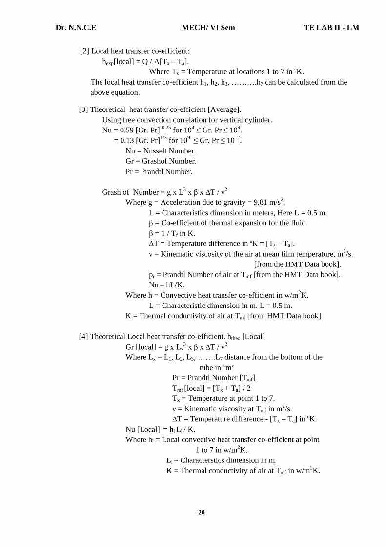
[2] Local heat transfer co-efficient: hexp[local] = Q / A[Tx – Ta]. Where Tx = Temperature at locations 1 to 7 in 0K. The local heat transfer co-efficient h1, h2, h3, ……….h7 can be calculated from the
above equation.
[3] Theoretical heat transfer co-efficient [Average]. Using free convection correlation for vertical cylinder. Nu = 0.59 [Gr. Pr] 0.25 for 104 ≤ Gr. Pr ≤ 109. = 0.13 [Gr. Pr]1/3 for 109 ≤ Gr. Pr ≤ 1012. Nu = Nusselt Number. Gr = Grashof Number. Pr = Prandtl Number. Grash of Number = g x L3 x β x ∆T / ν2 Where g = Acceleration due to gravity = 9.81 m/s2. L = Characteristics dimension in meters, Here L = 0.5 m. β = Co-efficient of thermal expansion for the fluid
β = 1 / Tf in K. ∆T = Temperature difference in 0K = [Ts – Ta]. ν = Kinematic viscosity of the air at mean film temperature, m2/s.
[from the HMT Data book]. pr = Prandtl Number of air at Tmf [from the HMT Data book]. Nu = hL/K. Where h = Convective heat transfer co-efficient in w/m2K. L = Characteristic dimension in m. L = 0.5 m. K = Thermal conductivity of air at Tmf [from HMT Data book] [4] Theoretical Local heat transfer co-efficient. htheo [Local] Gr [local] = g x Lx
3 x β x ∆T / ν2 Where Lx = L1, L2, L3, …….L7 distance from the bottom of the tube in ‘m’ Pr = Prandtl Number [Tmf] Tmf [local] = [Tx + Ta] / 2 Tx = Temperature at point 1 to 7. ν = Kinematic viscosity at Tmf in m2/s. ∆T = Temperature difference - [Tx – Ta] in 0K. Nu [Local] = hl Ll / K. Where hl = Local convective heat transfer co-efficient at point
1 to 7 in w/m2K. Ll = Characterstics dimension in m. K = Thermal conductivity of air at Tmf in w/m2K.

Dr. N.N.C.E MECH/ VI Sem TE LAB II - LM
21
Result: Thus the average surface heat transfer co-efficient and local heat transfer co-efficient along the length of the tube are determined and also the graph b/w local heat transfer co-efficient and the distance along the height of the tube is drawn. The results are tabulated. Experiment local heat transfer co-efficient:
S. No. Input
[watts] Local heat transfer co-efficient [w/m2K] [experiment]
Average Surface
Heat Transfer
Co-efficient [w/m2K]
h1 h2 h3 h4 h5 h6 h7 1. 50 68.45 57.045 42.784 34.227 36.672 31.17 39.493 41.309
Theortical Local heat transfer co-efficient:
S. No. Input
[watts]
[Theortical]Local heat transfer co-efficient experiment [w/m2K]
Average Heat
Transfer Co-
efficient [w/m2K]
h1 h2 h3 h4 h5 h6 h7 1. 50 9.349 6.54 5.909 5.235 4.658 4.502 4.048 3.983
VIVA QUESTIONS 1. What is meant by free or natural convection?
It is fluid motion is produced due to change in density resulting from temperature gradients, the mode of heat transfer is said to be free or natural convection.
2. Define Grashof number [Gr]. It is defined as the ratio of product of inertia force and buoyancy force to the
square of viscous force. Gr = Inertia force x Buoyancy force / [Viscous force]2 3. Define Stanton number [St].
It is the ratio of Nusselt number to the product of Reynolds number and Prandtl number. St = Nu / Re x Pr.
4. What is meant by Newtonion and non-newtonion fluids? The fluids which obey the Newton’s law of viscosity are called Newtonion
fluids and those which do not obey are called no-newtonion fluids. 5. What is meant by laminar flow ?
Laminar flow: Laminar flow is sometimes called stream line flow. In this type of flow, the fluid moves in layers and each fluid particle follows a smooth continuous path. The fluid particles in each layer remain in an orderly sequence without mixing with each other.

Dr. N.N.C.E MECH/ VI Sem TE LAB II - LM
22
Experiment Number: 4 Title of the Experiment: Forced Convection inside Tube
Date of the Experiment:
OBJECTIVE [AIM] OF THE EXPERIMENT
To determine the heat transfer coefficient on the given Forced Convection inside tube
Apparatus.
FACILITIES REQUIRED AND PROCEDURE
a] Facilities required to do the experiment:
Sl. No.
Facilities Required
Quantity
1. Forced Convection inside tube Apparatus 1
b] Description
The experimental setup consists of a tube through which air is sent in by a blower. The test section consists of a long electrical surface heater on the tube which serves as a constant heat flux source on the flowing medium. The inlet and outlet temperatures of the flowing air are measured by thermocouples and also the temperatures at several locations along the surface heater from which on average temperature can be obtained. An orifice meter in the tube is used to measure the air flow rate with a ‘U tube water manometer. An ammeter and a voltmeter are provided to measure the power input to the heater. A power regulator is provided to vary the power input to heater. A multipoint digital temperature indicator is provided to measure the above thermocouples input. A valve is provided to regulate the flow rate of air. c] Procedure for doing the experiment:
Step No. Details of the Step 1. Switch on the main. 2. Switch on the blower. 3. Adjust the regulator to any desired power into input to heater. 4. Adjust the position of the valve to any desired flow rate of air. 5. Wait till steady state temperature is reached. 6. Note manometer reading h1 and h2. 7. Note temperatures along the tube. Note air inlet and outlet temperature. 8. Note voltmeter and ammeter reading. 9. Adjust the position of the valve and vary the flow rate of air and repeat the
experiment. 10. For various valve openings and for various power inputs the readings may
be taken to repeat the experiments.

Dr. N.N.C.E MECH/ VI Sem TE LAB II - LM
23
TABULATION:
S.No. Voltage
[V] [Volts]
Current [A]
[Amps]
Inlet Temperature of air [T1]
[0C]
Outlet Temperature of air [T6]
[0C]
Temperature along the duct
Manometer reading
T2 [0C]
T3 [0C]
T4 [0C]
T5 [0C]
h1
[cm] h2
[cm]
1
50
1
35
38
42
45
46
47
9
19
MODEL CALCULATIONS: EXPERIMENTAL METHOD: PI = V x I = 50 watts VI = h x A x ∆t ∆t = Average temperature of heater – Average temperature of air ∆t = 45 – 36.5 ∆t = 8.50C Average temperature of heater = T2 + T3 + T4 + T5 / 4 = 42+45+46+47 / 4 = 450C. Average temperature of air = T1 + T6 / 2 = 35 + 33 / 2 = 36.50C. A = Area of heat transfer A = π x d x l Diameter of tube d = 0.04m Length of the tube l = 0.5m A = 3.14 x 0.04 x 0.5 A = 0.0634m2. VI = h x A x ∆t 50 = h X 0.0634 X 8.5 h = 92.782 W/m2C. THEORTICAL METHOD Q = Cd x a1 x a2 √2gho / √a1
2 – a22
ho = [h1 – h2] x [ρw/ρa] m3/sec
ρw = 1000 kg/m3 ρa = 1.16 kg/m3.
Dr. N.N.C.E MECH/ VI Sem TE LAB II - LM
24
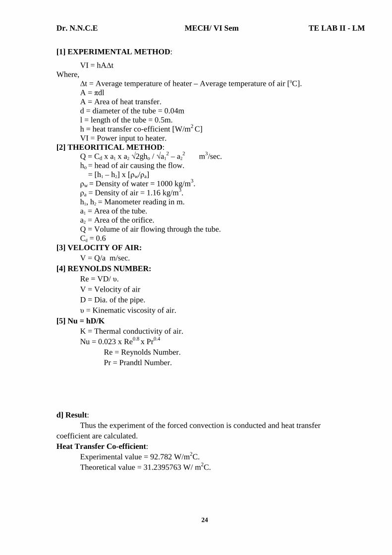
[1] EXPERIMENTAL METHOD :
VI = hA∆t Where, ∆t = Average temperature of heater – Average temperature of air [0C]. A = πdl A = Area of heat transfer. d = diameter of the tube = 0.04m l = length of the tube = 0.5m. h = heat transfer co-efficient [W/m2 C] VI = Power input to heater. [2] THEORITICAL METHOD : Q = Cd x a1 x a2 √2gho / √a1
2 – a22 m3/sec.
ho = head of air causing the flow. = [h1 – h2] x [ρw/ρa] ρw = Density of water = 1000 kg/m3. ρa = Density of air = 1.16 kg/m3. h1, h2 = Manometer reading in m. a1 = Area of the tube. a2 = Area of the orifice. Q = Volume of air flowing through the tube. Cd = 0.6 [3] VELOCITY OF AIR: V = Q/a m/sec. [4] REYNOLDS NUMBER: Re = VD/ υ. V = Velocity of air D = Dia. of the pipe. υ = Kinematic viscosity of air. [5] Nu = hD/K K = Thermal conductivity of air. Nu = 0.023 x Re0.8 x Pr0.4 Re = Reynolds Number. Pr = Prandtl Number. d] Result: Thus the experiment of the forced convection is conducted and heat transfer coefficient are calculated. Heat Transfer Co-efficient:
Experimental value = 92.782 W/m2C. Theoretical value = 31.2395763 W/ m2C.
Dr. N.N.C.E MECH/ VI Sem TE LAB II - LM
25
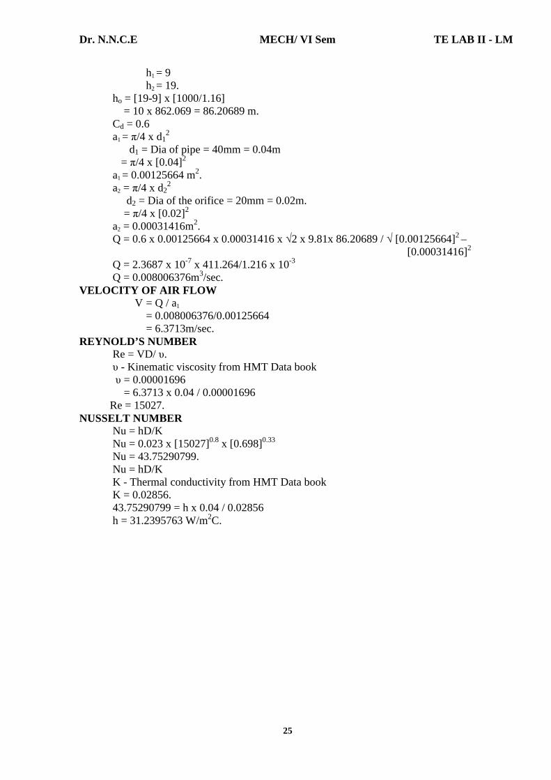
h1 = 9 h2 = 19. ho = [19-9] x [1000/1.16] = 10 x 862.069 = 86.20689 m. Cd = 0.6 a1 = π/4 x d1
2 d1 = Dia of pipe = 40mm = 0.04m = π/4 x [0.04]2 a1 = 0.00125664 m2. a2 = π/4 x d2
2 d2 = Dia of the orifice = 20mm = 0.02m. = π/4 x [0.02]2 a2 = 0.00031416m2. Q = 0.6 x 0.00125664 x 0.00031416 x √2 x 9.81x 86.20689 / √ [0.00125664]2 – [0.00031416]2 Q = 2.3687 x 10-7 x 411.264/1.216 x 10-3
Q = 0.008006376m3/sec. VELOCITY OF AIR FLOW
V = Q / a1 = 0.008006376/0.00125664 = 6.3713m/sec.
REYNOLD’S NUMBER Re = VD/ υ.
υ - Kinematic viscosity from HMT Data book υ = 0.00001696
= 6.3713 x 0.04 / 0.00001696 Re = 15027. NUSSELT NUMBER Nu = hD/K Nu = 0.023 x [15027]0.8 x [0.698]0.33
Nu = 43.75290799. Nu = hD/K
K - Thermal conductivity from HMT Data book K = 0.02856.
43.75290799 = h x 0.04 / 0.02856 h = 31.2395763 W/m2C.

Dr. N.N.C.E MECH/ VI Sem TE LAB II - LM
26
VIVA QUESTIONS
1. Define Convection. Convection is a process of heat transfer that will occur between a solid surface
and a fluid medium when they are at different temperatures. 2. Define Reynolds number [Re].
It is defined as the ratio of inertia force to viscous force. Re = Inertia force / Viscous force
3. Define Prandtl number [Pr]. It is the ratio of the momentum diffusivity to the thermal diffusivity.
Pr = Momentum diffusivity / Thermal diffusivity 4. Define Nusselt Number [Nu].
It is defined as the ratio of the heat flow by convection process under an unit temperature gradient to the heat flow rate by conduction under an unit temperature gradient through a stationary thickness [L] of metre. Nusselt Number [Nu] = qconv /qcond
5. State Newton’s law of convection. Heat transfer from the moving fluid to solid surface is given by the equation.
Q = h A = [Tw - T∞] This equation is referred to as Newton’s law of cooling. Where h = Local heat transfer coefficient in W/m2K. A = Surface area in m2. Tw = Surface [or] Wall temperature in K. T∞ = Temperature of fluid in K.
6. What is forced convection? If the fluid motion is artificially created by means of an external force like a
blower or fan, that type of heat transfer is known as forced convection. 7. What are the dimensionless parameters used in forced convection?
1. Reynolds number [Re]. 2. Nusselt number [Nu]. 3. Prandtl number [Pr].

Dr. N.N.C.E MECH/ VI Sem TE LAB II - LM
27
Experiment Number: 5 Title of the Experiment: Heat transfer from pin-fin (natural & forced convection modes) Date of the Experiment:
OBJECTIVE [AIM] OF THE EXPERIMENT To determine Heat transfer from pin-fin(natural & forced convection modes) . FACILITIES REQUIRED AND PROCEDURE a] Facilities required to do the experiment:
Sl. No. Facilities required Quantity 1. Pin-fin Apparatus 1
b] Apparatus Description The heat transfer from a heated surface to the ambient surrounding is given by the relation, q = h A ∆T. In this relation hc is the convective heat transfer coefficient, ∆T is the temperature difference & A is the area of heat transfer. To increase q, h may be increased or surface area may by increased. In some cases it is not possible to increase the value of heat transfer coefficient & the temperature difference ∆T & thus the only alternative is to increase the surface area of heat transfer. The surface area is increased by attaching extra material in the form of rod (circular or rectangular) on the surface where we have to increase the heat transfer rate. "This extra material attached is called the extended surface or fin."The fins may be attached on a plane surface, and then they are called plane surface fins. If the fins are attached on the cylindrical surface, they are called circumferential fins. The cross section of the fin may be circular, rectangular, triangular or parabolic. c] Procedure for doing the experiment: Step No. Details of the Step
1. Connect the equipment to electric power supply. 2. Keep the thermocouple selector switch to zero position. 3. Turn the Variac (dimmerstat) clockwise and adjust the power input to the heater to
the desired value and switch on the blower. 4. Set the air–flow rate to any desired value by adjusting the difference in mercury
levels in the manometer and allow the unit to stabilize. 5. Note down the temperatures, T1 to T6 from the thermocouple selector switch. 6. Note down the difference in level of the manometer and repeat the experiment for
different power inputs to the heater. 7. Connect the equipment to electric power supply. 8. Keep the thermocouple selector switch to zero position.
FORMULA:

Dr. N.N.C.E MECH/ VI Sem TE LAB II - LM
28
Where;
d0 = Diameter of the Orifice; dp = Diameter of the pipe
Where;
ρρρρm = density of manometric fluid = 13.6 x 10³ kg/m³
ρρρρa = density of air = 1.17 kg/m³
Velocity at orifice x cross sectional area of orifice Va = Velocity of air in the duct = Cross sectional area of duct V0 x (ππππd0²)/4 Va = = W x B
Where,
dp = diameter of pipe
d0 = diameter of orifice
W = Width of the duct
B = Breadth of duct
Average surface temperature of fin is given by
T1 + T2 + T3 + T4 + T5
Ts = + 273.15 = K 5 T∞∞∞∞ = T6 = Ambient temperature = + 273.15 = K
Tm = Mean temperature = Ts + T∞∞∞∞
2
Properties of air at _____0C
ν = , Pr = , K =
Va df
Re = ----------- = Re = Reynolds number ν Pr = Prandtl number
Nu = Nusselt number
The relationship for Nu is
n 1/3
Nu = C Re Pr
Dr. N.N.C.E MECH/ VI Sem TE LAB II - LM
29
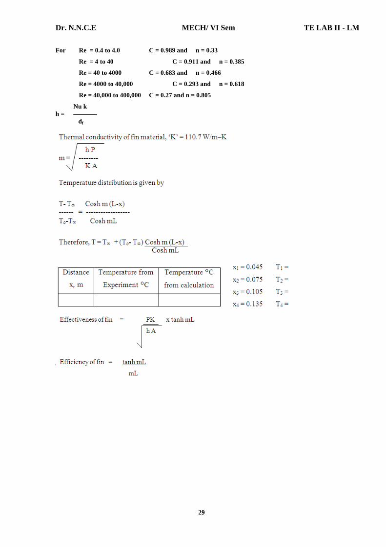
For Re = 0.4 to 4.0 C = 0.989 and n = 0.33
Re = 4 to 40 C = 0.911 and n = 0.385
Re = 40 to 4000 C = 0.683 and n = 0.466
Re = 4000 to 40,000 C = 0.293 and n = 0.618
Re = 40,000 to 400,000 C = 0.27 and n = 0.805
Nu k h = df
TABULATION:

Dr. N.N.C.E MECH/ VI Sem TE LAB II - LM
30
TABULATION:
CALCULATION:
1 . β = = = 0.4 Thermal Expansion β = 0.4 2. Velocity of ofifice :
X(1/1-β)
.
d] Result: Thus the heat transfer coefficient under forced convection is found out the efficiency of fin. (i).Theoretical value of temperature of fin= 327 K (ii).Effectiveness of fin=0.6 (iii).Efficiency of fin=40%
Sl.
No.
Heat Input Pressure drop, ‘h’
mm of mercury,
Temperatures, 0C
V A T1 T2 T3 T4 T5 T6
1
61
0.27
5mm 70
62
58
56
54
40

Dr. N.N.C.E MECH/ VI Sem TE LAB II - LM
31
VIVA QUESTIONS 1. What is fin?
Fins are extended surfaces used primarily to enhance the heat transfer rate between the solid fins and an adjoining fluid
2. Define Fin effectiveness
3. List out the Fin types.
1. Straight fin of uniform cross section 2. Straight fin of non-uniform cross section 3. Annular fin 4. Pin fin
5. Sketch all types of fins

Dr. N.N.C.E MECH/ VI Sem TE LAB II - LM
32
Experiment Number: 6 Title of the Experiment: Determination of stefan-boltzmann constant Date of the Experiment:
OBJECTIVE [AIM] OF THE EXPERIMENT To determine the value of Stefan boltzman constant for radiation heat transfer. FACILITIES REQUIRED AND PROCEDURE a] Facilities required to do the experiment:
Sl. No. Facilities required Quantity 1. Stefan-Boltzmann constant Apparatus 1
b] Apparatus Description
The apparatus consists of a flanged copper hemisphere fixed on a flat non-
conducting plate. A test disc made of copper is fixed to the plate. Thus the test disc is
completely enclosed by the hemisphere. The outer surface of the hemisphere is enclosed in a
vertical water jacket used to heat the hemisphere to a suitable constant temperature. Three
Cr-Al thermocouples are attached at four strategic places on the surface of the hemisphere to
obtain the temperatures. The disc is mounted on an ebonite rod which is fitted in a hole
drilled at the center of the base plate. Another Cr-Al thermocouple is fixed to the disc to
record its temperature. Fill the water in the SS water container with immersion heater kept on
top of the panel.
c] Procedure for doing the experiment: Step No. Details of the Step
1. Remove the test disc before starting the experiment. 2. Heat the water in the ss containers to its boiling point . 3. Allow the boiling water into the container kept at the bottom containing copper
bemisphere units it is full .allow sufficient time to attain thermal equilibrium which is indicated by the four thermocouple provided on the hemisphere.
4. Insert the test disc fixed on the ebonite rod sleeve completwly inside and lock it. Start the stop clock simultaneously .
5. Note down the temperature of the test disc at an inter val of about 15 sec for about 15 to 20 minutes.
6. Remove the test disc before starting the experiment. 7. Heat the water in the ss containers to its boiling point . 8. Allow the boiling water into the container kept at the bottom containing copper
bemisphere units it is full .allow sufficient time to attain thermal equilibrium which is indicated by the four thermocouple provided on the hemisphere.
Dr. N.N.C.E MECH/ VI Sem TE LAB II - LM
33
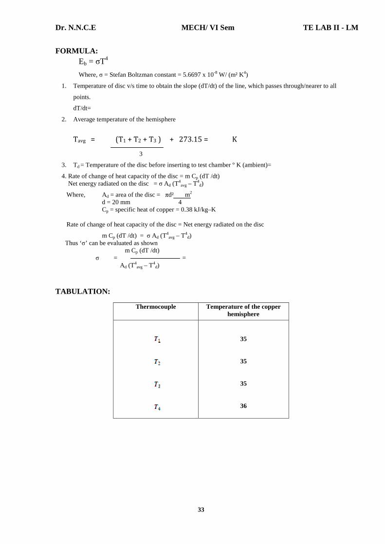
FORMULA: Eb = σT4
Where, σ = Stefan Boltzman constant = 5.6697 x 10⁻⁸ W/ (m² K4)
1. Temperature of disc v/s time to obtain the slope (dT/dt) of the line, which passes through/nearer to all
points.
dT/dt=
2. Average temperature of the hemisphere
Tavg = (T1 + T2 + T3 ) + 273.15 = K
3
3. Td = Temperature of the disc before inserting to test chamber º K (ambient)=
4. Rate of change of heat capacity of the disc = m Cp (dT /dt) Net energy radiated on the disc = σ Ad (T
4avg – T4
d)
Where, Ad = area of the disc = πd² m2 d = 20 mm 4 Cp = specific heat of copper = 0.38 kJ/kg–K Rate of change of heat capacity of the disc = Net energy radiated on the disc
m Cp (dT /dt) = σ Ad (T4avg – T4
d) Thus ‘σ’ can be evaluated as shown
m Cp (dT /dt) σ = = Ad (T
4avg – T4
d) TABULATION:
Thermocouple Temperature of the copper hemisphere
35
35
35
36
Dr. N.N.C.E MECH/ VI Sem TE LAB II - LM
34
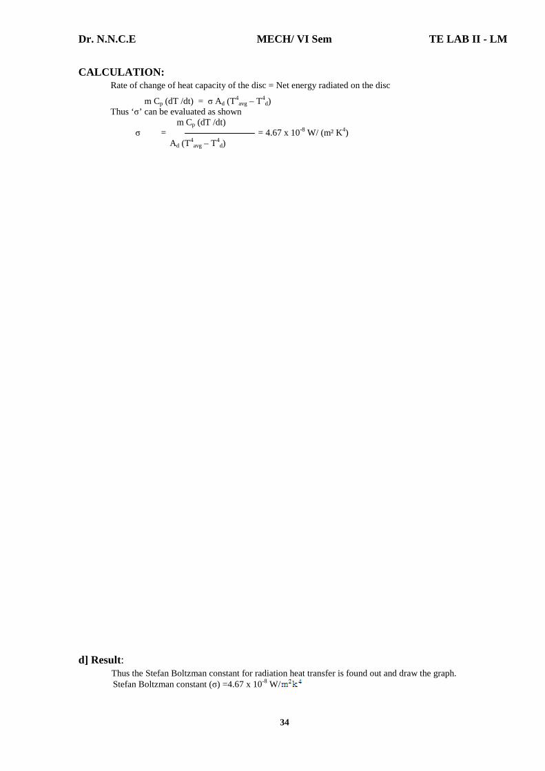
CALCULATION: Rate of change of heat capacity of the disc = Net energy radiated on the disc
m Cp (dT /dt) = σ Ad (T4avg – T4
d) Thus ‘σ’ can be evaluated as shown
m Cp (dT /dt) σ = = 4.67 x 10⁻⁸ W/ (m² K4) Ad (T
4avg – T4
d)
d] Result: Thus the Stefan Boltzman constant for radiation heat transfer is found out and draw the graph. Stefan Boltzman constant (σ) =4.67 x 10⁻⁸ W/

Dr. N.N.C.E MECH/ VI Sem TE LAB II - LM
35
VIVA QUESTIONS 1. Mention Stefan boltzman contant.
σ = Stefan Boltzman constant = 5.6697 x 10⁻⁸ W/ (m² K4) 2. Define Stefan boltzman contant.
Stefan Boltzman law states that the total emissive power of a perfect black body is proportional to
fourth power of the absolute temperature of black body surface
Eb = σT4
σ = Stefan Boltzman constant = 5.6697 x 10⁻⁸ W/ (m² K4)
3. Define Emissive power [Eb]. The emissive power is defined as the total amount of radiation emitted by a body per unit time
and unit area. It is expressed in W/m2. 4. Define monochromatic emissive power. [Ebλ]
The energy emitted by the surface at a given length per unit time per unit area in all directions is known as monochromatic emissive power.
5. What is meant by absorptivity? Absorptivity is defined as the ratio between radiation absorbed and incident radiation.
Absorptivity, α = Radiation absorbed / Incident radiation.

Dr. N.N.C.E MECH/ VI Sem TE LAB II - LM
36
Experiment Number: 7 Title of the Experiment: Determination of Emissivity of a Grey Surface
Date of the Experiment:
OBJECTIVE [AIM] OF THE EXPERIMENT To determine the emissivity of the test plate at any desired temperature. FACILITIES REQUIRED AND PROCEDURE a] Facilities required to do the experiment:
Sl. No. Facilities required Quantity 1. Emissivity Measurement Apparatus 1
b] Apparatus Description The experimental setup consists of two circular Al plates identical in size and is provided with heating coils at the bottom. The plates are mounted on an asbestos cement sheet and are kept in an enclosure so as to provide undisturbed natural convection surroundings. The heat input to the heaters is varied by separate dimmerstats and is measured by a wattmeter with the help of a double pole double throw switch. The temperatures of the plates are measured by separate thermocouples which are connected diametric opposite points to get the average temperature of the places. Other thermocouples are kept in the enclosure to read the ambient temperature.
Plate 1 is blackened by a thick layer of lamp black to form the idealized black surface where as the plates 2 is the test plate whose emissivity is to be determined. c] Procedure for doing the experiment: Step No. Details of the Step
1. Switch on the power supply. 2. Keep the thermocouple selector switch in first position. 3. Adjust the position of the regulator to provide desired input to heater. 4. Allow the unit to stabilize. 5. Note down the temperature indicated by temperature indicator. 6. Tabulate the readings and calculate. 7. After the experiment is over turn both the energy regulators 1 and 2 to zero position. 8. For various power input repeat the experiment.
FORMULA:
Emissivity εp = εb[Tb4 – Ta4] / [Tp4 – Ta4]
Where εb = Emissivity block body Temperature [εb = 1] Tb = Block Body Temperature in K. Tp = Polished Body Temperature in K. Ta = Chamber Temperature in K.

Dr. N.N.C.E MECH/ VI Sem TE LAB II - LM
37
TABULATION:
S.No. Voltage Current Black Body
Temperature [0C]
Polished Body Temperature
[0C]
Chamber Temperature
[0C] 1
100
0.4
80
90
40
CALCULATION: [1] Black body Temperature [Tb] = 800 + 273 = 353 K. [2] Polished body Temperature [Tp] = 900 + 273 = 363 K. [3] Chamber Temperature [Ta] = 400 + 273 = 313 K. EMISSIVITY:
εp = εb [Tb4 – Ta4] / [Tp4 – Ta4] [εb = 1] = 1 x [3534 – 3134] / [3634 – 3134] = [1.55 x 10¹⁰ – 9.59 x 10⁹] / [1.736 x 10¹⁰ – 9.59 x10⁹]
εp = 0.7626.
d] Result: Thus the Emissivity of the test plate is determined.
Emissivity εp = 0.7626.
Dr. N.N.C.E MECH/ VI Sem TE LAB II - LM
38
VIVA QUESTIONS 6. Define Radiation.
The heat transfer from one body to another without any transmitting medium is known as radiation. It is an electromagnetic wave phenomenon.
7. Define Emissivity. It is defined as the ability of the surface of a body to radiate heat. It is also
defined as the ratio of emissive power of any body to the emissive power of a black body of equal temperature.
Emissivity, ε = E / Eb. 8. Define Emissive power [Eb].
The emissive power is defined as the total amount of radiation emitted by a body per unit time and unit area. It is expressed in W/m2.
9. Define monochromatic emissive power. [Ebλ] The energy emitted by the surface at a given length per unit time per unit area
in all directions is known as monochromatic emissive power. 10. What is meant by absorptivity?
Absorptivity is defined as the ratio between radiation absorbed and incident radiation. Absorptivity, α = Radiation absorbed / Incident radiation.
11. What is meant by reflectivity? Reflectivity is defined as the ratio of radiation reflected to the incident
radiation. Reflectivity, ρ = Radiation reflected / Incident radiation.
12. What is meant by transmissivity? Transmissivity is defined as the ratio of radiation transmitted to the incident
radiation. Transmissivity, τ = Radiation transmitted / Incident radiation.
13. What is black body? Black body is an ideal surface having the following properties.
1. A black body absorbs all incident radiation, regardless of wav e length and direction.
2. For a prescribed temperature and wave length, no surface can emit more energy than black body.
14. What is meant by gray body? If a body absorbs a definite percentage of incident radiation irrespective of
their wave length, the body is known as gray body. The emissive power of a gray body is always less than that of the black body.

Dr. N.N.C.E MECH/ VI Sem TE LAB II - LM
39
PARALLEL FLOW SIDE
HOT WATER SIDE
COLD WATER SIDE
Flow rate [kg/s]
Thi [0C]
Tho [0C]
Flow rate [kg/s]
Tci [0C]
Tco [0C]
400ml/10sec. 56 45 400ml/12sec 34 39 COUNTER FLOW SIDE
HOT WATER SIDE
COLD WATER SIDE
Flow rate [kg/s]
Thi [0C]
Tho [0C]
Flow rate [kg/s]
Tci [0C]
Tco [0C]
800ml/10sec. 82 57 800ml/15sec 35 51 CALCULATION: PARALLEL FLOW : LMTD = [Thi – Tci] - [Tho – Tco] / ln [Thi – Tci/Tho – Tco] Tci = Entry temperature of cold fluid [0C]. Tco = Exit temperature of cold fluid [0C]. Thi = Entry temperature of hot fluid [0C]. Tho = Exit temperature of hot fluid [0C]. = [329 – 307] – [318 – 312] / ln [(329 – 307) / (318 – 312)] = 12.31 K. Mass flow rate of hot water mh = 400/10 x 10-6 x 1000 = 400 x 10-4 Kg/s. Mass flow rate of cold water mc = 400 / 12 x 10-6 x 1000 = 333.3 x 10⁻⁴ Kg/s. Qh = mh x Cph [Thi – Tho] = 400 x 10-4 x 4.187 x [329 – 318] Qh = 1.842 KJ/sec. Qc = mc x cpc [Tco –Tci] = 333.3 x 10-4 x 4.187 [312 – 307] Qc = 0.698 KJ/sec.
Qact = [Qh + Qc] / 2 = [1.842 + 0.698] / 2
Qact = 1.27 KJ/sec.
Overall heat transfer co-efficient A = π x D x L
= π x 0.013 x 1.5 = 0.06123 m2.
U = Qact/A x LMTD = 1.27 / 0.06123 x 12.31 = 1.685 W/m2K. U = Overall heat transfer co-efficient.

Dr. N.N.C.E MECH/ VI Sem TE LAB II - LM
40
Experiment Number: 8 Title of the Experiment: Effectiveness Of Parallel / Counter Flow Heat
Exchanger Date of the Experiment:
OBJECTIVE [AIM] OF THE EXPERIMENT To determine the overall heat transfer co-efficient on the given double pipe parallel flow and counter flow heat exchanger. FACILITIES REQUIRED AND PROCEDURE a] Facilities required to do the experiment:
Sl. No.
Facilities required
Quantity
1.
Parallel/Counter flow heat exchanger apparatus.
1
b] Theory: A heat exchanger is defined as equipment which transfers the heat from a hot fluid to a cold fluid. Types of Heat Exchanger There are several types of heat exchangers which may be classified on the basis of
I. Nature of heat exchange process II. Relative direction of fluid motion III. Design and constructional features IV. Physical state of fluids.
I. Nature of heat exchange process On the basis of the nature of heat exchange process, heat exchangers are classified as a] Direct contact heat exchangers or Open heat exchangers b] Indirect contact heat exchangers. a] Direct contact heat exchangers or Open heat exchangers In direct contact heat exchanger, the heat exchange takes place by direct mixing of hot and cold fluids. This heat transfer is usually accompanied by mass transfer. Examples: Cooling towers, direct contact feed heaters. b. Indirect contact heat exchangers In this type of heat exchangers, the transfer of heat between two fluids could be carried out by transmission through a wall which separates the two fluids. It may be classified as [i] Regenerators [ii] Recuperators [or] Surface heat exchangers.
Dr. N.N.C.E MECH/ VI Sem TE LAB II - LM
41
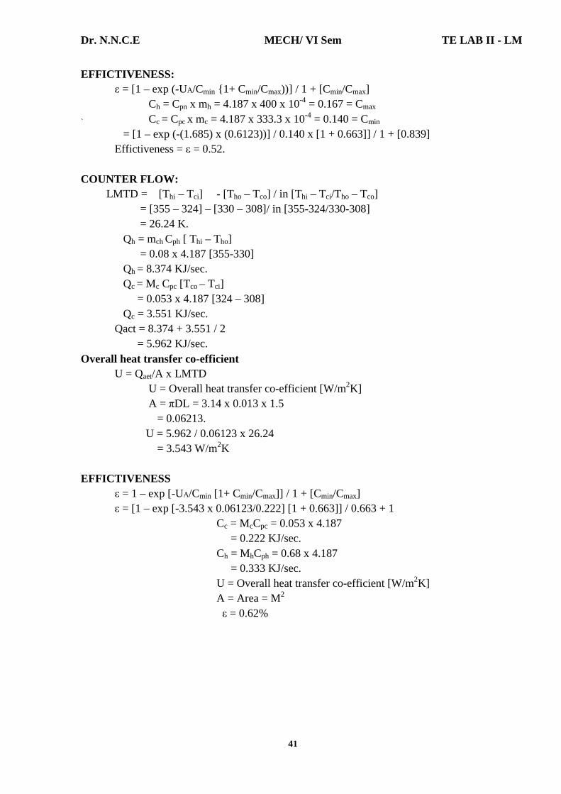
EFFICTIVENESS: ε = [1 – exp (-UA/Cmin {1+ Cmin/Cmax))] / 1 + [Cmin/Cmax] Ch = Cpn x mh = 4.187 x 400 x 10-4 = 0.167 = Cmax
` Cc = Cpc x mc = 4.187 x 333.3 x 10-4 = 0.140 = Cmin = [1 – exp (-(1.685) x (0.6123))] / 0.140 x [1 + 0.663]] / 1 + [0.839] Effictiveness = ε = 0.52. COUNTER FLOW: LMTD = [Thi – Tci] - [Tho – Tco] / in [Thi – Tci/Tho – Tco] = [355 – 324] – [330 – 308]/ in [355-324/330-308] = 26.24 K. Qh = mch Cph [ Thi – Tho] = 0.08 x 4.187 [355-330] Qh = 8.374 KJ/sec. Qc = Mc Cpc [Tco – Tci] = 0.053 x 4.187 [324 – 308] Qc = 3.551 KJ/sec.
Qact = 8.374 + 3.551 / 2 = 5.962 KJ/sec.
Overall heat transfer co-efficient U = Qaet/A x LMTD U = Overall heat transfer co-efficient [W/m2K] A = πDL = 3.14 x 0.013 x 1.5 = 0.06213. U = 5.962 / 0.06123 x 26.24 = 3.543 W/m2K EFFICTIVENESS ε = 1 – exp [-UA/Cmin [1+ Cmin/Cmax]] / 1 + [Cmin/Cmax] ε = [1 – exp [-3.543 x 0.06123/0.222] [1 + 0.663]] / 0.663 + 1 Cc = McCpc = 0.053 x 4.187 = 0.222 KJ/sec. Ch = MhCph = 0.68 x 4.187 = 0.333 KJ/sec. U = Overall heat transfer co-efficient [W/m2K] A = Area = M2 ε = 0.62%

Dr. N.N.C.E MECH/ VI Sem TE LAB II - LM
42
[i] Regenerators In this type of heat exchangers, hot and cold fluids flow alternately through the same space. Examples: IC engines, gas turbines. [ii] Recuperators [or] Surface heat exchangers This is the most common type of heat exchanger in which the hot and cold fluid do not come into direct contact with each other but are separated by a tube wall or a surface. Examples: Automobile radiators, Air pre heaters, Economisers etc. Advantages
1. Easy construction 2. More economical 3. More surface area for heat transfer.
Disadvantages 1. Less heat transfer co-efficient 2. Less generating capacity.
II. Relative direction of fluid motion This type of heat exchangers are classified as follows a] Parallel flow heat exchanger b] Counter flow heat exchanger c] Cross flow heat exchanger. a] Parallel flow heat exchanger In this type, hot and cold fluids move in the same direction. b] Counter flow heat exchanger In this type, hot and cold fluids move in parallel but opposite directions. c] Cross flow heat exchanger In this type, the hot and cold fluids move at right angles to each other. III Design and constructional features On the basis of design and constructional features, the heat exchangers are classified as follows. a] Concentric tubes b] Shell and tube c] Multiple shell and tube passes d] Compact heat exchangers. a] Concentric tubes In this type, two concentric pipes, each carrying one of the fluids are used as a heat exchanger. The direction of flow may be parallel or counter. b] Shell and tube In this type of heat exchanger, one or the fluids move through a bundle of tubes enclosed by a shell. The other fluid is forced through the shell and it moves over the outside surface of the tubes. c] Multiple shell and tube passes In order to increase the over all heat transfer, multiple shell and tube passes are used. In this type, the two fluids traverse the exchanger more than one time. This type of exchanger is preferred due to its low cost of manufacture, and easy to repair.

Dr. N.N.C.E MECH/ VI Sem TE LAB II - LM
43
d] Compact heat exchangers There are many special purpose heat exchangers called compact heat exchangers. They are generally employed when convective heat transfer co-efficient associated with one of the fluids is much smaller than that associated with the other fluid. IV Physical state of fluids Based on the physical state of fluids inside the exchanger, heat exchangers are classified as a] Condensers b] Evaporators. a] Condensers In a condenser, the condensing fluid remains at constant temperature throughout the exchanger while the temperature of the colder fluid gradually increased from inlet to outlet. In other words, the hot fluid loses latent heat which is accepted by the cold fluid. b] Evaporators In a evaporator, the cold fluid remains at constant temperature while the temperature of hot fluid gradually decreases from inlet to outlet.
APPARATUS DESCRIPTION Apparatus consists of the constrict tube heat exchanger. The hot fluid that is hot water is obtained from an electric geyser and it flows through the outer tube. The cold fluid that is cold water can be admitted at one of the ends enabling the heat exchanger to run as parallel flow apparatus [or] a counter flow apparatus. This can be done by operating the different valves can be provided. Temperature of the fluid can be measured using thermometer. Flow rate can be measured using stopwatch and measuring clock. The outer tube is provided with adequate asbestos rope insulation to minimize the heat loss to the surroundings. FORMULA USED: Heat Transfer rate ‘q’ is calculated Qh = Heat transfer rate from hot water. Qh = mh x Cph [Thi – Tho] Where mh = Mass flow rate of hot water [Kg/s] Cph = Specific heat of hot water [KJ/KgK] Thi = Hot water inlet temperature [0C] Tho = Hot water outlet temperature [0C] Qc = Heat Transfer rate to the cold water Qc = mc x Cpc [Tco- Tci] Where mc = Mass flow rate of cold water [Kg/s] Cpc = Specific heat of cold water [KJ/KgK] Tco = Cod water outlet temperature [0C] Tci = Cold water inlet temperature [0C]
Dr. N.N.C.E MECH/ VI Sem TE LAB II - LM
44
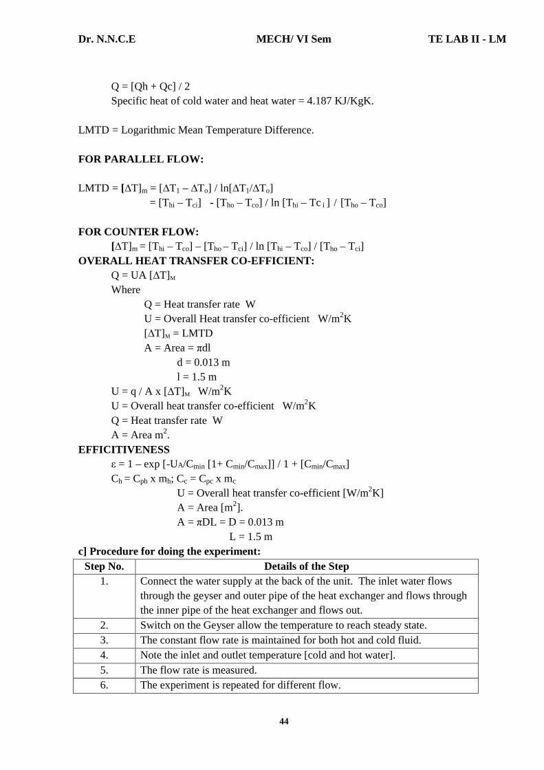
Q = [Qh + Qc] / 2 Specific heat of cold water and heat water = 4.187 KJ/KgK. LMTD = Logarithmic Mean Temperature Difference. FOR PARALLEL FLOW: LMTD = [∆T]m = [∆T1 – ∆To] / ln[∆T1/∆To] = [Thi – Tci] - [Tho – Tco] / ln [Thi – Tc i ] / [Tho – Tco] FOR COUNTER FLOW: [∆T]m = [Thi – Tco] – [Tho – Tci] / ln [Thi – Tco] / [Tho – Tci] OVERALL HEAT TRANSFER CO-EFFICIENT: Q = UA [∆T]M
Where Q = Heat transfer rate W U = Overall Heat transfer co-efficient W/m2K [∆T]M = LMTD A = Area = πdl d = 0.013 m l = 1.5 m U = q / A x [∆T]M W/m2K U = Overall heat transfer co-efficient W/m2K Q = Heat transfer rate W A = Area m2. EFFICITIVENESS ε = 1 – exp [-UA/Cmin [1+ Cmin/Cmax]] / 1 + [Cmin/Cmax] Ch = Cph x mh; Cc = Cpc x mc U = Overall heat transfer co-efficient [W/m2K] A = Area [m2]. A = πDL = D = 0.013 m L = 1.5 m c] Procedure for doing the experiment:
Step No. Details of the Step 1. Connect the water supply at the back of the unit. The inlet water flows
through the geyser and outer pipe of the heat exchanger and flows through the inner pipe of the heat exchanger and flows out.
2. Switch on the Geyser allow the temperature to reach steady state. 3. The constant flow rate is maintained for both hot and cold fluid. 4. Note the inlet and outlet temperature [cold and hot water]. 5. The flow rate is measured. 6. The experiment is repeated for different flow.

Dr. N.N.C.E MECH/ VI Sem TE LAB II - LM
45
d] Result: Thus the heat transfer experiment was conducted in a double pipe parallel flow and counter flow heat exchanger. PARALLEL FLOW: COUNTER FLOW LMTD = 12.31 K LMTD = 26.24 K Heat Transfer Q = 1.27 KJ/sec. Heat Transfer Q = 5.962 KJ/sec. Overall heat transfer Overall heat transfer co-efficient U = 1.685 W/m2K co-efficient U = 3.543 W/m2K Effictiveness ε = 0.52 = 52% Effictiveness ε = 0.62 = 62% VIVA QUESTIONS
1. What is heat exchanger? A heat exchanger is defined as an equipment which transfers the heat from a
hot fluid to a cold fluid. 2. What is meant by Direct heat exchanger [or] open heat exchanger?
In direct contact heat exchanger, the heat exchange takes place by direct mixing of hot and cold fluids.
3. What is meant by Indirect contact heat exchanger? In this type of heat exchangers, the transfer of heat between two fluids could
be carried out by transmission through a wall which separates the two fluids. 4. What is meant by parallel flow heat exchanger?
In this type of heat exchanger, hot and cold fluids move in the same direction. 5. What is meant by counter flow heat exchanger?
In this type of heat exchanger, hot and cold fluids move in parallel but opposite directions.
6. What is meant by cross flow heat exchanger? In this type of heat exchanger, hot and cold fluids move at right angles to each
other. 7. What is meant by Shell and tube heat exchanger?
In this type of heat exchanger, one of the fluids moves through a bundle of tubes enclosed by a shell. The other fluid is forced through the shell and it moves over the outside surface of the tubes.
8. What is meant by LMTD? We know that the temperature difference between the hot and cold fluids in
the heat exchanger varies from point to point. In addition various modes of heat transfer are involved. Therefore based on concept of appropriate mean temperature difference, also called logarithmic mean temperature difference, the total heat transfer rate in the heat exchanger is expressed as Q = U A [∆T]m Where, U=Overall heat transfer co-efficient [W/m2K], A=Area, m2 [∆T]m = Logarithmic mean temperature difference.
9. What is meant by Effectiveness? The heat exchanger effectiveness is defined as the ratio of actual heat transfer
to the maximum possible heat transfer. Effectiveness ε = Actual heat transfer / Maximum possible heat transfer = Q / Qmax
Dr. N.N.C.E MECH/ VI Sem TE LAB II - LM
46
Experiment Number: 9 Title of the Experiment: Determination of COP of a Refrigeration System Date of the Experiment:
OBJECTIVE [AIM] OF THE EXPERIMENT To determine the [i] Theoretical COP, [ii] Experimental COP, [iii] Carnot COP, [iv] Relative COP on a refrigeration system. FACILITIES REQUIRED AND PROCEDURE a] Facilities required to do the experiment:
Sl. No. Facilities required Quantity 1. Refrigeration test rig. 1
b] Description Vapour compression cycle is widely used refrigeration cycle. The main object of the trainer is to demonstrate refrigeration system with basic components and necessary controls. The practical working is demonstrated in the system and considerable amount of theoretical analysis and performance can be studied. The trainer consists of components of a refrigeration system viz. Hermetically sealed components, evaporator, condenser, capillary tube. The condenser is air cooled type for which a condenser fans and motor has been provided. Evaporator is water immersion type which is housed in a thermally insulated calorimeter. Calorimeter is provided with a electric heater which can be used for heating the water initially to be desired temperature. In addition to capillary tube a thermostatic expansion valve is also provided. We have to select either a capillary tube or thermostatic expansion valve at a time. A toggle switch has been provided to facilitate this selection. A temperature indicator with six point selection switch has been provided to get the various temperature of Freon – 12 viz. Compressor suction, compressor discharge after condenser and after expansion and water temperature. Special gauges have been provides for indicating Freon – 12 pressure at above mentioned points except for colorimeter water. An energy meter has been provided which indicates the consumption of energy of compressor. An additional energy meter has been provided to indicate the energy consumption of water heater. The students are advised to find out the saturation temperature of F – 12 after knowing the pressures at various points and based on the saturation temperatures study the working of refrigeration considering the cycle based on [a] Reversed Carnot cycle, [b] Simple vapour compression cycle.

Dr. N.N.C.E MECH/ VI Sem TE LAB II - LM
47
TABULATION
S. No.
Time [s]
Energy Meter
Reading For 10 Rev. in
sev.
Pressure Temperature [0C]
P1 P2 P3 P4 T1 T2 T3 T4 T5
1.. 2. 3. 4. 5. 6. 7. 8.
2.15 2.25 2.35 2.45 2.55 3.05 3.15 3.25
176 186 191 201 206 209 212 208
25
22.5 24 24 25 24 24 24
195 195 195 200 200 200 200 200
150 150 160 160 160 165 170 170
20 20 22 22 25 25 24 22
20 20 22 22 22 24 26 20
52 53 54 55 53 51 49 46
22 24 23 24 24 26 23 27
-12 -14 -13 -15 -17 -19 -21 -20
29.5 29 28 27 26 22 19 16
Quantity of water in tank: 10 kg. Initial temperature of water: 300C.] Pressure in bar: Convert all the pressures in [PSIG] to bar [multiply the value in PSIG by 0.06894 and add 1.013 to convert to bar abs.] P1 = 25 x 0.06894 + 1.013 = 2.736 bar. P2 = 195 x 0.06894 + 1.013 = 14.456 bar. P3 = 150 x 0.06894 + 1.013 = 11.354 bar.
P4 = 20 x 0.06894 + 1.013 = 2.391 bar. [1] Total Refrigerant Effect:
Q = mCp ∆T/∆t. Q = 10 x 4.186 x [30-16] / 60 x 60 Q = 0.1627 KJ/sec. [2] Theoretical COP. = [h1 - h3]/ [h2 - h1] h1 corresponding to P1 and T1 = 370 KJ/kg. h2 corresponding to P2 and T2 = 382 KJ/kg. h3 = h4 corresponding to P3 and T3 = 350 KJ/kg. Where h1, h2, h3 are enthalpies of refrigerant taken from p-h chart. Theoretical COP = [370 – 350] / [382 – 370] Theoretical C.O.P. = 1.667.
Dr. N.N.C.E MECH/ VI Sem TE LAB II - LM
48
The interested students can also study the saturation temperature against the actual temperatures obtained during the experimentation and thus study the actual cycle of refrigeration system. Specification: [1] Compressor: Hermetically sealed compressor. [2] Air cooled condenser. [3] Expansion valve [a] Capillary tube. [b] Thermostatic Expansion valve. [4] Evaporator. [5] Rota meter: For liquid refrigerant flow rate. [6] Refrigerant: Freon – 12. [7] Energy meters for power measurement of compressor and the fans and heater. [8] Pressure gauges – 4 Nos. [Two for H.P. and Two for L.P.] [9] Temperature indicator. [10] Solenoid valves. [11] H.P. / L.P. cut out. [12] Ammeter. [13] Voltmeter. [14] Thermostat. c] Procedure for doing the experiment:
Step No. Details of the Step 1. Switch on the main. 2. Switch on the fan motor and then compressor motor. 3. Allow the plant to run to reach steady conditions. Take readings for every
10 minutes to know the steady state. 4. Observe the readings in compressor motor energy meter. Freon flow
meter, pressure gauges and thermometer and record it is a tubular form. 5. Switch off the plant after experiment is over by switching off the
compressor motor first. Allow the fan motors to run for 10 minutes and then switch off.
Specimen Calculations: P1 = Pressure of the Refrigerant before the compressor. P2 = Pressure of the Refrigerant after the compressor. P3 = Pressure of the Refrigerant before the expansion valve. P4 = Pressure of the Refrigerant after the expansion valve. Sensor Meter Reading: T1 = Temperature of Refrigerant before compression. T2 = Temperature of Refrigerant after compression. T3 = Temperature of Refrigerant before evaporation. T4 = Temperature of Refrigerant after evaporation.

Dr. N.N.C.E MECH/ VI Sem TE LAB II - LM
49
[3] Experimental COP Time for 10 rev. of energy meter, t = 208 sec.
t = 208 sec. Energy consumed by the compressor P = 10/t x 1/1500 x 3600 x 0.9 KW. = 10/208 x 1/1500 x 3600 x 0.9 P = 0.104 KW. Experimental COP = Actual Refrigeration effect / workdone = Q / p = 0.1627 / 0.104 Experimental COP = 1.564. [4] Carnot COP = TL / [TH - TL] TL = Pmin = [P1 + P4] / 2 = [2.736 + 2.391] / 2 = 2.5635 bar.
TH = Pmax = [P2 + P3] / 2 = [14.456 + 2.391] / 2 = 12.905 bar. Lowest Temperature from table.
TL = -120C = 261 K. Corresponding to Pmin Highest Temperature from table. TH = 560C = 329 K Corresponding to Pmax
Carnot COP = TL/TH - TL
= 261 / [329 – 261] = 3.84.
[5] Relative COP = Actual COP / Carnot COP = 1.564 / 3.84 = 0.407.
Dr. N.N.C.E MECH/ VI Sem TE LAB II - LM
50
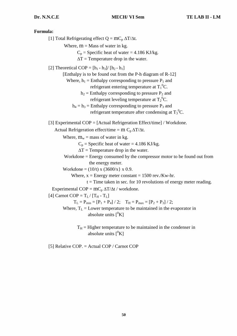
Formula:
[1] Total Refrigerating effect Q = mCp ∆T/∆t.
Where, m = Mass of water in kg. Cp = Specific heat of water = 4.186 KJ/kg. ∆T = Temperature drop in the water.
[2] Theoretical COP = [h1 - h3]/ [h2 - h1] [Enthalpy is to be found out from the P-h diagram of R-12] Where, h1 = Enthalpy corresponding to pressure P1 and refrigerant entering temperature at T1
0C. h2 = Enthalpy corresponding to pressure P2 and refrigerant leveling temperature at T2
0C. h4 = h3 = Enthalpy corresponding to pressure P3 and refrigerant temperature after condensing at T3
0C.
[3] Experimental COP = [Actual Refrigeration Effect/time] / Workdone.
Actual Refrigeration effect/time = m Cp ∆T/∆t.
Where, mw = mass of water in kg. Cp = Specific heat of water = 4.186 KJ/kg. ∆T = Temperature drop in the water. Workdone = Energy consumed by the compressor motor to be found out from the energy meter. Workdone = (10/t) x (3600/x} x 0.9. Where, x = Energy meter constant = 1500 rev./Kw-hr. t = Time taken in sec. for 10 revolutions of energy meter reading.
Experimental COP = mCp ∆T/∆t / workdone. [4] Carnot COP = TL / [TH - TL] TL = Pmin = [P1 + P4] / 2; TH = Pmax = [P2 + P3] / 2; Where, TL = Lower temperature to be maintained in the evaporator in absolute units [0K] TH = Higher temperature to be maintained in the condenser in absolute units [0K] [5] Relative COP. = Actual COP / Carnot COP

Dr. N.N.C.E MECH/ VI Sem TE LAB II - LM
51
d] Result: The COP of the Refrigeration system were determined and tabulated.
Theortical COP. Experimental [Actual] COP
Carnot COP Relative COP
1.667
1.564
3.34
0.407
VIVA QUESTIONS
1. Power requirement of a refrigerator is___________. Inversely proportional to COP.
2. In SI units, one ton of refrigeration is equal to _________. 210 kJ/min.
3. Define tons of refrigeration and COP. A tonne of refrigeration is defined as the quantity of heat required to be
removed from one tonne of water [1000 kg] at 00C to convert that into ice at 00C in 24 hours. In actual practice,
1 tonne of refrigeration = 210kJ/min = 3.5kW. 4. The capacity of a domestic refrigerator is in the range of ___________.
1 to 3 tonne. 5. Name four important properties of a good refrigerant.
1. Low boiling point. 2. High critical temperature & pressure. 3. Low specific heat of liquid.
6. What is the difference between air conditioning and refrigeration? Refrigeration is the process of providing and maintaining the temperature in
space below atmospheric temperature. Air conditioning is the process of supplying sufficient volume of clean air containing a specific amount of water vapour and maintaining the predetermined atmospheric condition with in a selected enclosure.
7. Name any four commonly used refrigerants. 1. Ammonia [NH3]. 2. Carbon dioxide [CO2]. 3. Sulphur di oxide [SO2]. 4. Freon – 12.

Dr. N.N.C.E MECH/ VI Sem TE LAB II - LM
52
8. What are the advantages and disadvantages of air refrigeration system? Advantages:
1. The refrigerant used namely air is cheap and easily available. 2. There is no danger of fire or toxic effects due to leakages. 3. The weight to tonne of refrigeration ratio is less as compared to other systems.
Disadvantages: 1. The quantity of refrigerant used per tonne of refrigeration is high as compared to other system. 2. The COP of the system is very low. Therefore running cost is high. 3. The danger of frosting at the expander valves is more as the air contains moisture content.
9. What is net refrigerating effect of the refrigerant? Refrigerating effect is the total heat removed from the refrigerant in the
evaporator. COP = Refrigeration effect / Work done. Refrigeration effect = COP x Work done.
10. Define refrigerant. Any substance capable of absorbing heat from another required substance can
be used as refrigerant.
Dr. N.N.C.E MECH/ VI Sem TE LAB II - LM
53
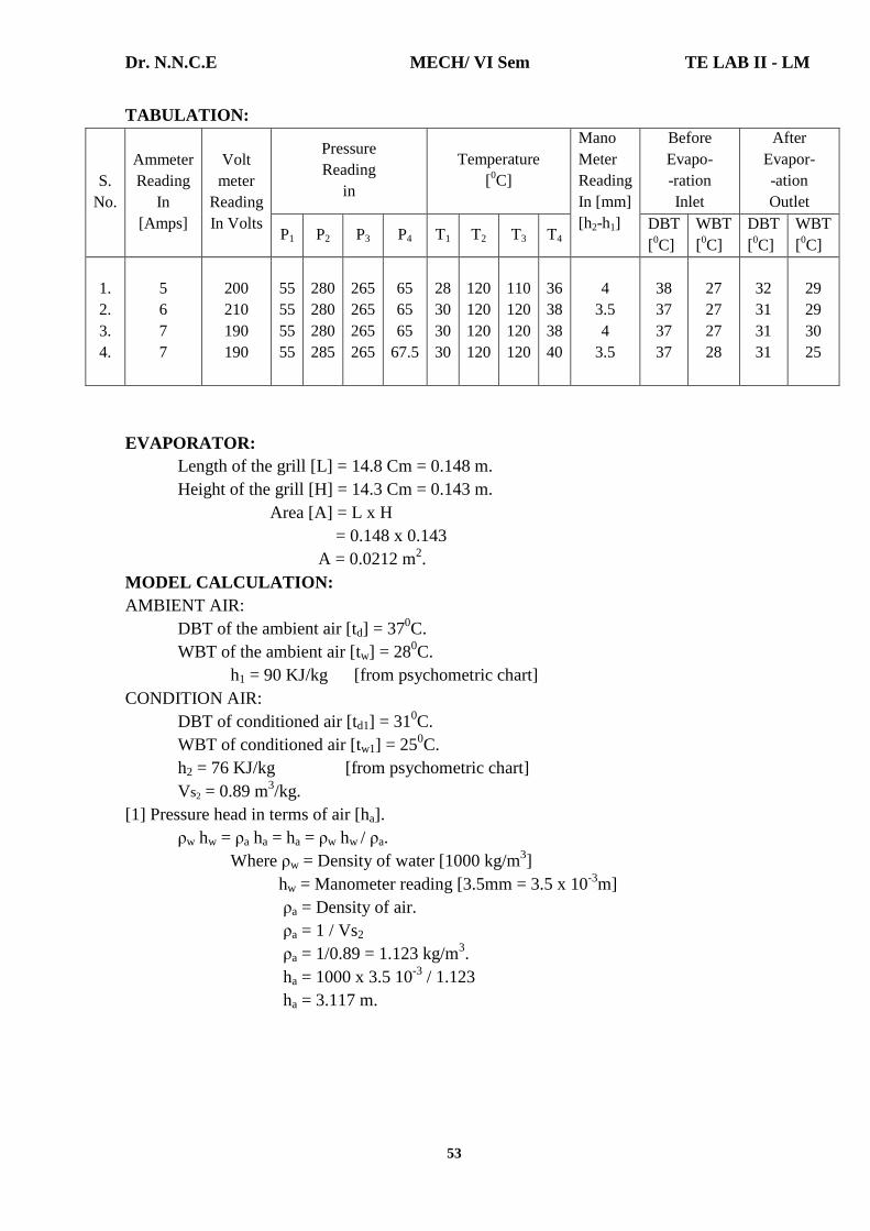
TABULATION:
S. No.
Ammeter Reading
In [Amps]
Volt meter
Reading In Volts
Pressure Reading
in
Temperature [0C]
Mano Meter Reading In [mm] [h2-h1]
Before Evapo- -ration Inlet
After Evapor- -ation Outlet
P1 P2 P3 P4 T1 T2 T3 T4 DBT [0C]
WBT [0C]
DBT [0C]
WBT [0C]
1. 2. 3. 4.
5 6 7 7
200 210 190 190
55 55 55 55
280 280 280 285
265 265 265 265
65 65 65
67.5
28 30 30 30
120 120 120 120
110 120 120 120
36 38 38 40
4
3.5 4
3.5
38 37 37 37
27 27 27 28
32 31 31 31
29 29 30 25
EVAPORATOR: Length of the grill [L] = 14.8 Cm = 0.148 m. Height of the grill [H] = 14.3 Cm = 0.143 m. Area [A] = L x H = 0.148 x 0.143 A = 0.0212 m2. MODEL CALCULATION: AMBIENT AIR: DBT of the ambient air [td] = 370C. WBT of the ambient air [tw] = 280C. h1 = 90 KJ/kg [from psychometric chart] CONDITION AIR: DBT of conditioned air [td1] = 310C. WBT of conditioned air [tw1] = 250C. h2 = 76 KJ/kg [from psychometric chart] Vs2 = 0.89 m3/kg. [1] Pressure head in terms of air [ha]. ρw hw = ρa ha = ha = ρw hw / ρa. Where ρw = Density of water [1000 kg/m3] hw = Manometer reading [3.5mm = 3.5 x 10⁻³m] ρa = Density of air. ρa = 1 / Vs2 ρa = 1/0.89 = 1.123 kg/m3. ha = 1000 x 3.5 10-3 / 1.123 ha = 3.117 m.

Dr. N.N.C.E MECH/ VI Sem TE LAB II - LM
54
Experiment Number: 10 Title of the Experiment: Experiments on Air Conditioning System Date of the Experiment:
OBJECTIVE [AIM] OF THE EXPERIMENT To determine the carnot COP, theoretical COP and capacity of the refrigeration and air conditioning system. FACILITIES REQUIRED AND PROCEDURE a] Facilities required to do the experiment:
Sl. No. Facilities required Quantity 1. Air-conditioning test rig. 1
b] Introduction: Air Conditioning for human comfort or industrial process requires certain processes to be carried out on air to vary the psychometric properties of air to requirements. These processes may involve the mixing of air streams, heating of air, cooling of the air, humidifying air, and dehumidifying air and combination of the process. All such processes are studied with the given air-condition test rig. c] Procedure for doing the experiment:
Step No. Details of the Step 1. Switch on the mains. 2. Switch on the condenser, fan and blower. 3. Switch on the compressor and allow the unit to stabilize. 4.
Note down the following. a] Pressure P1, P2, P3 and P4 from the respective pressure gauge. b] Note the corresponding Temperatures T1, T2, T3 and T4 at the respective state points. c] Monometer readings. d] Note DBT and WBT at the inlet of the duct [before evaporation]. e] Note DBT and WBT at the outlet of the duct [after evaporation].
FORMULA: DBT = Dry Bulb Temperature [Td] WBT = Wet Bulb Temperature [Tw] [1] ha = ρw hw / ρa
ρw = Density of water [1000 kg/m3]. hw = Manometer reading. ρa = Density of air [1.123 kg/m3].
[2] Va = Velocity of air Va = √2 x g x ha g = acceleration due to gravity 9.81m/s2.

Dr. N.N.C.E MECH/ VI Sem TE LAB II - LM
55
[2] Velocity of air [Va] Va = √2 x g x ha
= √2 x 9.81 x 3.117 Va = 7.82 m/s.
[3] Mass of air [ma] = ρa x A x Va
= 1.123 x 0.0212 x 7.82
ma = 0.186 kg/sec.
[4] Refrigeration effect = ma [h2 – h1]. = 0.186 [90-76] = 2.604 KJ/sec. [or] KW. [5] Capacity = Refrigeration effect / 3.5 = 2.604 / 3.5 [1 tonne of refrigeration = 210 KJ/min. = 3.5 KW] = 0.744 tonne of refrigeration. [6] Carnot COP = TL / [TH - TL] TL = Lower temperature to be maintained in the evaporator. P1 = 55 PSI = 55 x 0.07 + 1.013 = 4.863 bar. P4 = 67.5 PSI = 67.5 x 0.07 + 1.013 = 5.738 bar.
Pmin = [P1 + P4] / 2 = [4.863 + 5.738] / 2 = 5.3 bar. From Table R – 22 TL = 20C = 275 K
TH = Higher temperature to be maintained in the condenser. P2 = 285 PSI = 285 x 0.07 + 1.013 = 20.963 bar.
P3 = 270 PSI = 270 x 0.07 + 1.013 = 19.913 bar. Pmax = [P2 + P3] / 2 = [20.963 + 19.913] / 2 = 20.438 bar.
From Table Freon – 22, TH = 520C = 325 K. Carnot COP = TL / [TH - TL] = 275 / [325 – 275] = 5.5 Carnot COP = 5.5. [7] Theoretical COP
Theoretical COP = [h1–h3] / [h2–h1] [Where h1, h2, h3 are enthalpies of refrigerant taken from p-h chart.] P1 = 4.863 bar; T1 = 1.1120C; h1 = 260 KJ/kg. P2 = 5.738 bar; T2 = 48.880C; h2 = 300 KJ/kg. P3 = 19.913 bar; T3 = 48.880C; h3 = 100 KJ/kg. Theoretical COP = [260 – 100] / [300 – 260] Theoretical COP = 4.

Dr. N.N.C.E MECH/ VI Sem TE LAB II - LM
56
[3] Mass of air ma = ρa x A x Va ρa = Density of air [kg/m3] Va = Velocity of air [m/s] A = H x L
[4] Refrigeration effect = ma [h2 – h1]. h2 = Enthalpy of ambient air [KJ/kg.] h1 = Enthalpy of condition air [KJ/kg.] [5] Capacity = Refrigeration effect /3.5 [6] Carnot COP = TL / [TH - TL] TL = Lower temperature to be maintained in the evaporator in absolute
unit [0K]. TH = Higher temperature to be maintained in the condenser in absolute
unit [0K]. [7] Theoretical COP = [h1–h3] / [h2–h1] h1 corresponding to P1 and T1. h2 corresponding to P2 and T2. h3 corresponding to P3 and T3.
[Enthalpy is to be found out from the P-h diagram of R-22]
Dr. N.N.C.E MECH/ VI Sem TE LAB II - LM
57
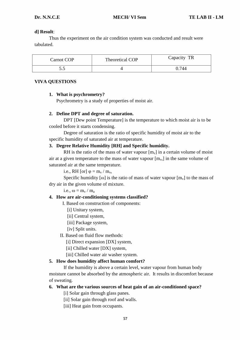
d] Result: Thus the experiment on the air condition system was conducted and result were tabulated.
Carnot COP Theoretical COP Capacity TR
5.5 4 0.744 VIVA QUESTIONS
1. What is psychrometry? Psychrometry is a study of properties of moist air.
2. Define DPT and degree of saturation. DPT [Dew point Temperature] is the temperature to which moist air is to be
cooled before it starts condensing. Degree of saturation is the ratio of specific humidity of moist air to the
specific humidity of saturated air at temperature. 3. Degree Relative Humidity [RH] and Specific humidity.
RH is the ratio of the mass of water vapour [mv] in a certain volume of moist air at a given temperature to the mass of water vapour [mvs] in the same volume of saturated air at the same temperature.
i.e., RH [or] φ = mv / mvs
Specific humidity [ω] is the ratio of mass of water vapour [mv] to the mass of dry air in the given volume of mixture.
i.e., ω = mv / ma 4. How are air-conditioning systems classified? I. Based on construction of components: [i] Unitary system, [ii] Central system,
[iii] Package system, [iv] Split units. II. Based on fluid flow methods: [i] Direct expansion [DX] system, [ii] Chilled water [DX] system, [iii] Chilled water air washer system. 5. How does humidity affect human comfort?
If the humidity is above a certain level, water vapour from human body moisture cannot be absorbed by the atmospheric air. It results in discomfort because of sweating. 6. What are the various sources of heat gain of an air-conditioned space?
[i] Solar gain through glass panes. [ii] Solar gain through roof and walls. [iii] Heat gain from occupants.
Dr. N.N.C.E MECH/ VI Sem TE LAB II - LM
58
[iv] Heat gain from appliances and lights. [v] Duct leakage. [vi] Infiltration. [vii] Vapour transmission.
7. Define bypass factor [BPF] of a coil. The ratio of the amount of air which does not contact the cooling coil [amount
of bypassing air] to the amount of supply air is called BPF. i.e., BPF = Amount of air bypassing the coil / Total amount of air passed.
8. What factors affect by pass factor? 1. Pitch of fins. 2. Number of coil tubes. 3. Air velocity over the coil. 4. Direction of air flow.
9. What are the requirements of comfort a/c? 1. Supply of O2 and removal of CO2. 2. Removal of heat of occupants. 3. Removal of moisture of occupants. 4. Good air distribution. 5. Maintaining air purity.
10. What factors affect effective temperature? 1. Climatic and seasonal differences. 2. Clothing. 3. Age and sex. 4. Activity. 5. Stay duration. 6. Air velocity.
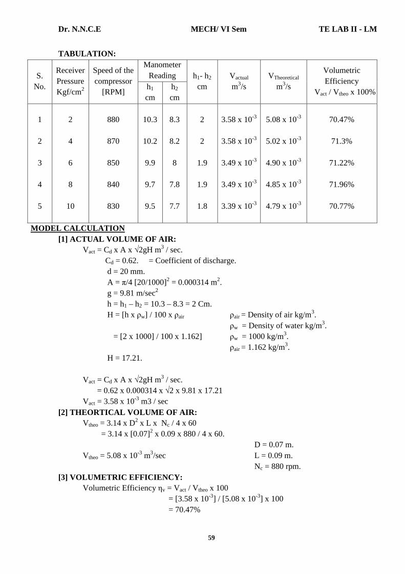
Dr. N.N.C.E MECH/ VI Sem TE LAB II - LM
59
TABULATION:
S. No.
Receiver Pressure Kgf/cm2
Speed of the compressor
[RPM]
Manometer Reading h1- h2
cm Vactual m3/s
VTheoretical
m3/s
Volumetric Efficiency
Vact / Vtheo x 100% h1 cm
h2 cm
1 2 3 4 5
2 4 6 8
10
880
870
850
840
830
10.3
10.2
9.9
9.7
9.5
8.3
8.2
8
7.8
7.7
2 2
1.9
1.9
1.8
3.58 x 10⁻³
3.58 x 10⁻³
3.49 x 10⁻³
3.49 x 10⁻³
3.39 x 10⁻³
5.08 x 10⁻³
5.02 x 10⁻³
4.90 x 10⁻³
4.85 x 10⁻³
4.79 x 10⁻³
70.47%
71.3%
71.22%
71.96%
70.77%
MODEL CALCULATION [1] ACTUAL VOLUME OF AIR: Vact = Cd x A x √2gH m3 / sec. Cd = 0.62. = Coefficient of discharge. d = 20 mm. A = π/4 [20/1000]2 = 0.000314 m2. g = 9.81 m/sec2 h = h1 – h2 = 10.3 – 8.3 = 2 Cm. H = [h x ρw] / 100 x ρair ρair = Density of air kg/m3. ρw = Density of water kg/m3. = [2 x 1000] / 100 x 1.162] ρw = 1000 kg/m3. ρair = 1.162 kg/m3. H = 17.21. Vact = Cd x A x √2gH m3 / sec. = 0.62 x 0.000314 x √2 x 9.81 x 17.21 Vact = 3.58 x 10⁻³ m3 / sec [2] THEORTICAL VOLUME OF AIR: Vtheo = 3.14 x D2 x L x Nc / 4 x 60 = 3.14 x [0.07]2 x 0.09 x 880 / 4 x 60. D = 0.07 m. Vtheo = 5.08 x 10⁻³ m3/sec L = 0.09 m. Nc = 880 rpm. [3] VOLUMETRIC EFFICIENCY: Volumetric Efficiency ηv = Vact / Vtheo x 100 = [3.58 x 10⁻³] / [5.08 x 10-3] x 100 = 70.47%
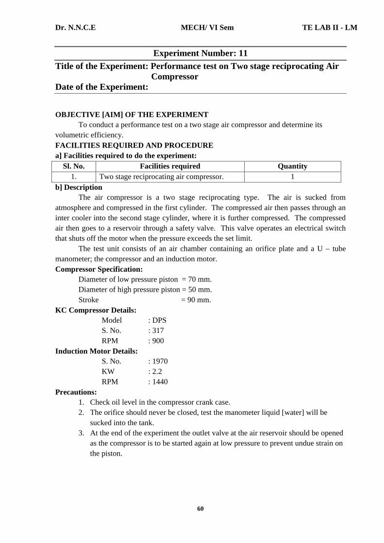
Dr. N.N.C.E MECH/ VI Sem TE LAB II - LM
60
Experiment Number: 11 Title of the Experiment: Performance test on Two stage reciprocating Air
Compressor Date of the Experiment:
OBJECTIVE [AIM] OF THE EXPERIMENT To conduct a performance test on a two stage air compressor and determine its volumetric efficiency. FACILITIES REQUIRED AND PROCEDURE a] Facilities required to do the experiment:
Sl. No. Facilities required Quantity 1. Two stage reciprocating air compressor. 1
b] Description The air compressor is a two stage reciprocating type. The air is sucked from atmosphere and compressed in the first cylinder. The compressed air then passes through an inter cooler into the second stage cylinder, where it is further compressed. The compressed air then goes to a reservoir through a safety valve. This valve operates an electrical switch that shuts off the motor when the pressure exceeds the set limit. The test unit consists of an air chamber containing an orifice plate and a U – tube manometer; the compressor and an induction motor. Compressor Specification: Diameter of low pressure piston = 70 mm. Diameter of high pressure piston = 50 mm. Stroke = 90 mm. KC Compressor Details: Model : DPS S. No. : 317 RPM : 900 Induction Motor Details: S. No. : 1970 KW : 2.2 RPM : 1440 Precautions:
1. Check oil level in the compressor crank case. 2. The orifice should never be closed, test the manometer liquid [water] will be
sucked into the tank. 3. At the end of the experiment the outlet valve at the air reservoir should be opened
as the compressor is to be started again at low pressure to prevent undue strain on the piston.
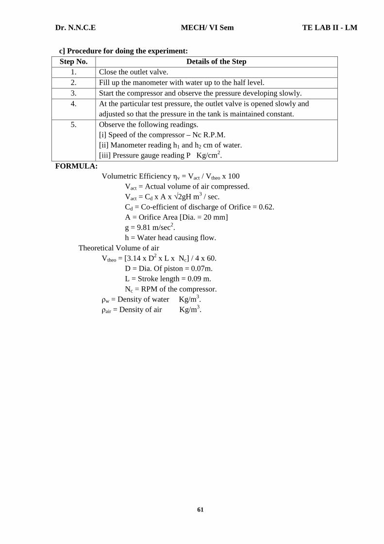
Dr. N.N.C.E MECH/ VI Sem TE LAB II - LM
61
c] Procedure for doing the experiment: Step No. Details of the Step
1. Close the outlet valve. 2. Fill up the manometer with water up to the half level. 3. Start the compressor and observe the pressure developing slowly. 4. At the particular test pressure, the outlet valve is opened slowly and
adjusted so that the pressure in the tank is maintained constant. 5. Observe the following readings.
[i] Speed of the compressor – Nc R.P.M. [ii] Manometer reading h1 and h2 cm of water. [iii] Pressure gauge reading P Kg/cm2.
FORMULA: Volumetric Efficiency ηv = Vact / Vtheo x 100 Vact = Actual volume of air compressed. Vact = Cd x A x √2gH m3 / sec. Cd = Co-efficient of discharge of Orifice = 0.62. A = Orifice Area [Dia. = 20 mm] g = 9.81 m/sec2. h = Water head causing flow. Theoretical Volume of air Vtheo = [3.14 x D2 x L x Nc] / 4 x 60. D = Dia. Of piston = 0.07m. L = Stroke length = 0.09 m. Nc = RPM of the compressor. ρw = Density of water Kg/m3. ρair = Density of air Kg/m3.

Dr. N.N.C.E MECH/ VI Sem TE LAB II - LM
62
d] Result: Thus the volumetric efficiency of the reciprocating air compressor are determined.
S. No.
Pressure [Kgf/cm2]
Volumetric Efficiency [τvol]
1. 2. 3. 4. 5.
2 4 6 8 10
70.47% 71.3% 71.22% 71.96% 70.7%
VIVA QUESTIONS
1. Classify the various types of air-compressors. 1] According to the design and principle of operation a] Reciprocating compressors. b] Rotary compressors. 2] According to the action a] Single acting compressors. b] Double acting compressors. 3] According to the number of stages a] Single stage compressors. b] Multistage compressors. 4] According to the pressure limit a] Low pressure compressors. b] Medium pressure compressors. c] High pressure compressors. 5] According to the capacity a] Low capacity compressors [Volume delivered 0.15 m3/s or less]. b] Medium capacity compressors [Volume delivered 0.15 m3/s to 5m2/s]. c] High capacity compressors [Volume delivered is above 5 m3/s].
2. What is meant by single acting compressor? In single acting compressor, the suction, compression and delivery of air takes
place on one side of the piston. 3. What is meant by double acting compressor?
In double acting reciprocating compressor, the suction, compression and delivery of air takes place on both sides of the piston.
4. What is meant by single stage compressor? In single stage compressor, the compression of air from the initial pressure to
the final pressure is carried out in one cylinder only. 5. What is meant by multistage compressor?
In multistage compressor, the compression of the air from the initial pressure to the final pressure is carried out in more than one cylinder.

Dr. N.N.C.E MECH/ VI Sem TE LAB II - LM
63
6. Indicate the applications of reciprocating compressors in industry. The applications of compressed air are as follows:
1. Pneumatic brakes. 2. Pneumatic drills. 3. Pneumatic jacks. 4. Pneumatic lifts. 5. Spray painting. 6. Shop cleaning. 7. Injecting fuel in diesel engines. 8. Supercharging internal combustion engines. 9. Refrigeration and air conditioning systems.
7. Define the terms as applied to air compressors: Volumetric efficiency and isothermal compression efficiency. Volumetric efficiency: Volumetric efficiency is defined as the ratio of volume of free air sucked into the compressor per cycle to the stroke volume of the cylinder. ηVol = Volume of free air taken per cycle / Stroke volume of the cylinder. Isothermal compression efficiency: Isothermal efficiency is defined as the ratio between isothermal work to the actual work of the compressor. Isothermal efficiency, ηIsothermal = Isothermal work / Actual work. Mechanical efficiency: Mechanical efficiency is defined as the ratio between brake power to the indicated power. Mechanical efficiency, ηmech = Brake power / Indicated power.
8. Define clearance ratio. Clearance ratio is defined as the ratio of clearance volume to swept volume
[or] stroke volume. C = Vc / Vs Vc = clearance volume. Vs = swept volume.
9. Define isentropic efficiency. It is the ratio of the isentropic power to the brake power required to drive the
compressor. Isentropic efficiency = Isentropic power / Actual brake power.
10. What is compression ratio? Compression ratio is defined as the ratio between total volume and clearance
volume. Compression ratio = Total volume / Clearance volume.

Dr. N.N.C.E MECH/ VI Sem TE LAB II - LM
64
Experiment Number: 12 Title of the Experiment: Thermal Conductivity of insulating powder Date of the Experiment:
OBJECTIVE [AIM] OF THE EXPERIMENT To determine the Thermal Conductivity of insulating powder [a] Description The apparatus consists of two thin walled concentric copper spheres. The inner sphere houses the heating coil. The insulating powder [Asbestos powder – Lagging Material] is packed between the two shells. The powder supply to the heating coil is by using a dimmer stat and is measured by Voltmeter and Ammeter. Choromel Alumel thermocouples are use to measure the temperatures. Temperature readings in turn enable to find out the Thermal Conductivity of the insulating powder as an isotropic material and the value of Thermal Conductivity can be determined. Consider the transfer of heat by conduction through the wall of a hollow sphere formed by the insulating powdered layer packed between two thin copper spheres. Let, ri = Radius of inner sphere in meters. ro = Radius of outer sphere in meters. Ti = Average Temperature of the inner sphere in 0C. To = Average Temperature of the outer sphere in 0C. Where, Ti = [T1+T2+T3+T4] / 4 and To = [T5+T6+T7+T8+T9+T10] / 6 Note that T1 to T10 denote the temperature of thermocouples [1] to [10]. From the experimental values of q, Ti and To the unknown thermal conductivity K cal be determined as …… K = q[ro – ri] / 4πri x ro[T i+To] Specifications:
1. Radius of the inner copper sphere, ri = 50 mm. 2. Radius of the outer copper sphere, ro = 100 mm. 3. Voltmeter [0 – 100 – 200 V]. 4. Ammeter [0 – 2 Amps.] 5. Temperature Indicator 0 – 3000C calibrated for chromel alumel. 6. Dimmerstat 0 – 2A, 0 – 230 V. 7. Heater coil - Strip Heating Element sandwiched between mica sheets – 200 watts.
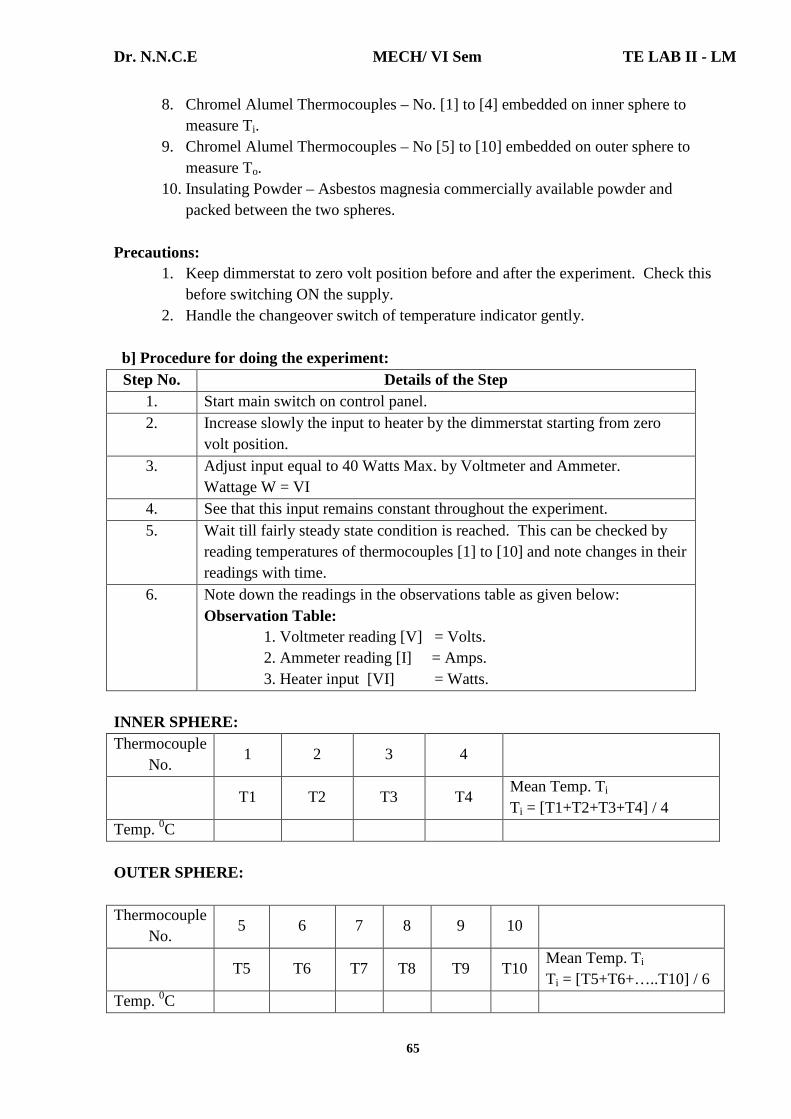
Dr. N.N.C.E MECH/ VI Sem TE LAB II - LM
65
8. Chromel Alumel Thermocouples – No. [1] to [4] embedded on inner sphere to measure Ti.
9. Chromel Alumel Thermocouples – No [5] to [10] embedded on outer sphere to measure To.
10. Insulating Powder – Asbestos magnesia commercially available powder and packed between the two spheres.
Precautions:
1. Keep dimmerstat to zero volt position before and after the experiment. Check this before switching ON the supply.
2. Handle the changeover switch of temperature indicator gently. b] Procedure for doing the experiment:
Step No. Details of the Step 1. Start main switch on control panel. 2. Increase slowly the input to heater by the dimmerstat starting from zero
volt position. 3. Adjust input equal to 40 Watts Max. by Voltmeter and Ammeter.
Wattage W = VI 4. See that this input remains constant throughout the experiment. 5. Wait till fairly steady state condition is reached. This can be checked by
reading temperatures of thermocouples [1] to [10] and note changes in their readings with time.
6. Note down the readings in the observations table as given below: Observation Table: 1. Voltmeter reading [V] = Volts. 2. Ammeter reading [I] = Amps. 3. Heater input [VI] = Watts.
INNER SPHERE: Thermocouple
No. 1 2 3 4
T1 T2 T3 T4
Mean Temp. Ti Ti = [T1+T2+T3+T4] / 4
Temp. 0C OUTER SPHERE: Thermocouple
No. 5 6 7 8 9 10
T5 T6 T7 T8 T9 T10
Mean Temp. Ti Ti = [T5+T6+…..T10] / 6
Temp. 0C
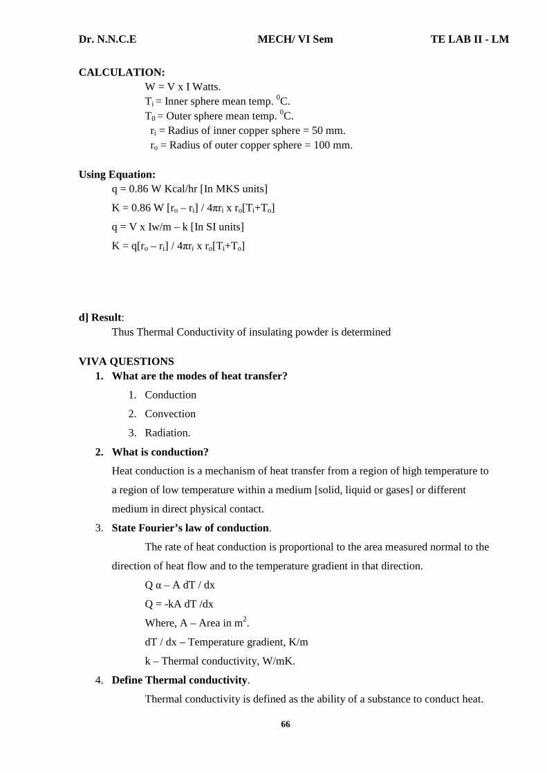
Dr. N.N.C.E MECH/ VI Sem TE LAB II - LM
66
CALCULATION: W = V x I Watts. Ti = Inner sphere mean temp. 0C. T0 = Outer sphere mean temp. 0C. ri = Radius of inner copper sphere = 50 mm. ro = Radius of outer copper sphere = 100 mm. Using Equation: q = 0.86 W Kcal/hr [In MKS units]
K = 0.86 W [ro – ri] / 4πri x ro[T i+To]
q = V x Iw/m – k [In SI units]
K = q[ro – ri] / 4πri x ro[T i+To]
d] Result:
Thus Thermal Conductivity of insulating powder is determined VIVA QUESTIONS
1. What are the modes of heat transfer?
1. Conduction
2. Convection
3. Radiation.
2. What is conduction?
Heat conduction is a mechanism of heat transfer from a region of high temperature to
a region of low temperature within a medium [solid, liquid or gases] or different
medium in direct physical contact.
3. State Fourier’s law of conduction.
The rate of heat conduction is proportional to the area measured normal to the
direction of heat flow and to the temperature gradient in that direction.
Q α – A dT / dx
Q = -kA dT /dx
Where, A – Area in m2.
dT / dx – Temperature gradient, K/m
k – Thermal conductivity, W/mK.
4. Define Thermal conductivity.
Thermal conductivity is defined as the ability of a substance to conduct heat.
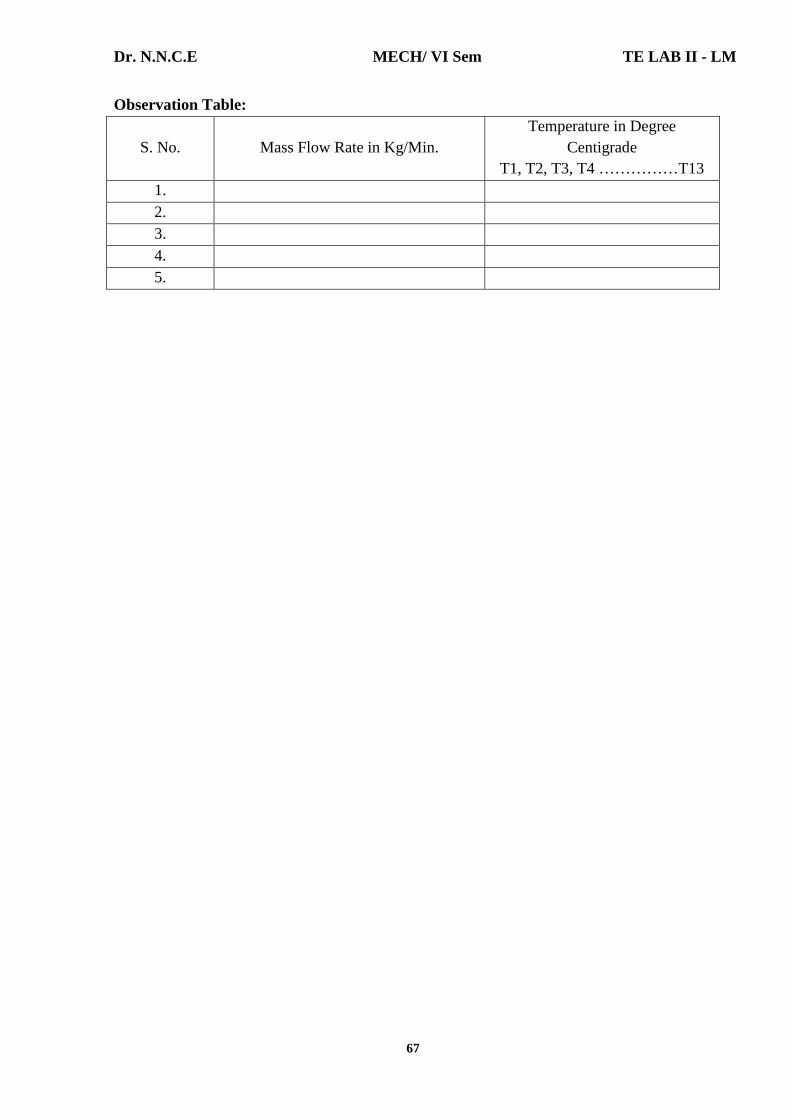
Dr. N.N.C.E MECH/ VI Sem TE LAB II - LM
67
Observation Table:
S. No. Mass Flow Rate in Kg/Min. Temperature in Degree
Centigrade T1, T2, T3, T4 ……………T13
1. 2. 3. 4. 5.
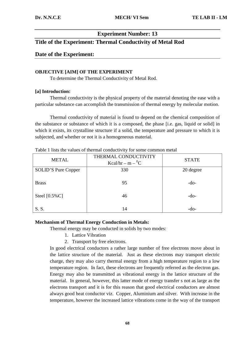
Dr. N.N.C.E MECH/ VI Sem TE LAB II - LM
68
Experiment Number: 13 Title of the Experiment: Thermal Conductivity of Metal Rod Date of the Experiment:
OBJECTIVE [AIM] OF THE EXPERIMENT To determine the Thermal Conductivity of Metal Rod. [a] Introduction: Thermal conductivity is the physical property of the material denoting the ease with a particular substance can accomplish the transmission of thermal energy by molecular motion. Thermal conductivity of material is found to depend on the chemical composition of the substance or substance of which it is a composed, the phase [i.e. gas, liquid or solid] in which it exists, its crystalline structure if a solid, the temperature and pressure to which it is subjected, and whether or not it is a homogeneous material. Table 1 lists the values of thermal conductivity for some common metal
METAL THERMAL CONDUCTIVITY
Kcal/hr – m – 0C STATE
SOLID’S Pure Copper Brass Steel [0.5%C] S. S.
330
95
46
14
20 degree
-do-
-do-
-do- Mechanism of Thermal Energy Conduction in Metals: Thermal energy may be conducted in solids by two modes:
1. Lattice Vibration 2. Transport by free electrons.
In good electrical conductors a rather large number of free electrons move about in the lattice structure of the material. Just as these electrons may transport electric charge, they may also carry thermal energy from a high temperature region to a low temperature region. In fact, these electrons are frequently referred as the electron gas. Energy may also be transmitted as vibrational energy in the lattice structure of the material. In general, however, this latter mode of energy transfer s not as large as the electrons transport and it is for this reason that good electrical conductors are almost always good heat conductor viz. Copper, Aluminium and silver. With increase in the temperature, however the increased lattice vibrations come in the way of the transport
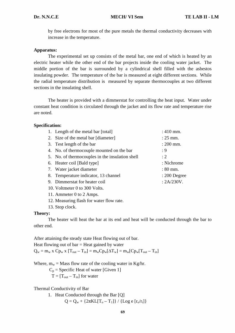
Dr. N.N.C.E MECH/ VI Sem TE LAB II - LM
69
by free electrons for most of the pure metals the thermal conductivity decreases with increase in the temperature.
Apparatus: The experimental set up consists of the metal bar, one end of which is heated by an electric heater while the other end of the bar projects inside the cooling water jacket. The middle portion of the bar is surrounded by a cylindrical shell filled with the asbestos insulating powder. The temperature of the bar is measured at eight different sections. While the radial temperature distribution is measured by separate thermocouples at two different sections in the insulating shell. The heater is provided with a dimmerstat for controlling the heat input. Water under constant heat condition is circulated through the jacket and its flow rate and temperature rise are noted. Specification:
1. Length of the metal bar [total] : 410 mm. 2. Size of the metal bar [diameter] : 25 mm. 3. Test length of the bar : 200 mm. 4. No. of thermocouple mounted on the bar : 9 5. No. of thermocouples in the insulation shell : 2 6. Heater coil [Bald type] : Nichrome 7. Water jacket diameter : 80 mm. 8. Temperature indicator, 13 channel : 200 Degree 9. Dimmerstat for heater coil : 2A/230V. 10. Voltmeter 0 to 300 Volts. 11. Ammeter 0 to 2 Amps. 12. Measuring flash for water flow rate. 13. Stop clock.
Theory: The heater will heat the bar at its end and heat will be conducted through the bar to other end. After attaining the steady state Heat flowing out of bar. Heat flowing out of bar = Heat gained by water Qw = mw x Cpw x [Tout – Tin] = mwCpw[∆Tw] = mw[Cpw[Tout – Tin] Where, mw = Mass flow rate of the cooling water in Kg/hr. Cp = Specific Heat of water [Given 1] T = [Tout – Tin] for water Thermal Conductivity of Bar
1. Heat Conducted through the Bar [Q] Q = Qw + {2πKL[T o – T1]} / {Log e [r o/ri]}

Dr. N.N.C.E MECH/ VI Sem TE LAB II - LM
70
Where, Qw = Heat conducted through water K = Thermal conductivity of Asbestos powder is 0.3 Kcal/hr – m – degree ro & r i = Radial distance of thermocouple in insulating shell.
2. Thermal conductivity of Bar [K] Q = K [dt/dx] x A
Where, dt = Change in temperature [T1 – T9] dx = Length across temperature [0.2] A = Area of the bar [π/4 x d2] π/4 x [0.025]2 = 4.9 x 10⁻⁴ m2
b] Procedure for doing the experiment:
Step No. Details of the Step 1. Start the electric supply. 2. Adjust the temperature in the temperature indicator by means of rotating
the knob for compensation of temperature equal to room temperature. [Normally this is per adjusted]
3. Give input to the heater by slowly rotating the dimmer stat and adjust it to voltage equal to 80 V, 120 V etc.
4. Start the cooling water supply through the jacket and adjust it about 350cc per minute.
5. Go on checking the temperature at some specified time interval say 5 minute and continue this till a satisfactory steady state condition is reached.
6. Note the temperature reading 1 to 13. 7. Note the mass flow rate of water in Kg/minute and temperature rise in it.
Observations: Mass flow rate of water [m] : Kg/min Water inlet temperature [T12] : Degree Centigrade Water outlet temperature [T13] : Degree Centigrade Rod Temperature [T1 to T9] : Degree Centigrade Radial distance of Thermocouples [ro] : 40 mm. Insulating shell [ri] : 25 mm. Specific heat of water [Cp] : 1 Kcal/Kg0K = 4.186 KJ/Kg K Thermal conductivity of Asbestos powder [K] : 0.3 Kcal/hr-m-0C 0.3 x 4.18 KJ/Kg K Length of bar [L] : 200 mm. Demeter of bar [d] : 50 mm Area of the bar [A] : 4.9 x 10⁻⁴ m2. Plot the temperature distribution along the length of the bar using observed values.

Dr. N.N.C.E MECH/ VI Sem TE LAB II - LM
71
CALCULATIONS:
1. Heat flowing out of bar. Q bar = Qw Qw = m x Cp x [∆Tw] [Kcal/hr] Where, m = Mass flow rate of the cooling water in Kg/hr. Cp = Specific Heat of water [Given 1] ∆Tw = [Tout – Tin] for water
2. Heat conducted through the bar [Q] Q = Qw + {2πKL[T10 – T11]} / {Log e [ro/ri]} [Kcal / Hr] Where, Qw = Heat conductivity of bar [K] K = Thermal conductivity of Asbestos powder is 0.3 Kcal/hr-m-degree ro& r i = Radial distance of thermocouple in insulating shell.
3. Thermal conductivity of Bar [K] Q = K [dt/dx] x A [Kcal/Hr-m-0C] Where, dt = Change in temperature [T1 – T9] dx = Length Across temperature [0.2] A = Area of the bar [n/4 x d2]. n/4 x [0.025]2 = 4.9 x 10⁻⁴ m2
c] Result:
Thus Thermal Conductivity of Metal Rod is determined.
VIVA QUESTIONS 1. Define heat transfer.
Heat transfer can be defined as the transmission of energy from one region to
another due to temperature difference.
2. What are the modes of heat transfer?
1. Conduction
2. Convection
3. Radiation.

Dr. N.N.C.E MECH/ VI Sem TE LAB II - LM
72
3. What is conduction?
Heat conduction is a mechanism of heat transfer from a region of high temperature to
a region of low temperature within a medium [solid, liquid or gases] or different
medium in direct physical contact.
4. State Fourier’s law of conduction.
The rate of heat conduction is proportional to the area measured normal to the
direction of heat flow and to the temperature gradient in that direction.
Q α – A dT / dx
Q = -kA dT /dx
Where, A – Area in m2.
dT / dx – Temperature gradient, K/m
k – Thermal conductivity, W/mK.
5. Define Thermal conductivity.
Thermal conductivity is defined as the ability of a substance to conduct heat.

Dr. N.N.C.E MECH/ VI Sem TE LAB II - LM
73
Observation Table:
Sl. No. Description Set - I Set - II
1. Volume of water collected during test period [m3] 2. Inlet temperature of water [T1
0C] 3. Outlet temperature [T2
0C] 4. Gas inlet temperature [Tact
0C] 5. Duration of test period [t sec.] 6. Volume of gas burnt during test period [Vg lit] 7. Barometer reading [mm Hg]

Dr. N.N.C.E MECH/ VI Sem TE LAB II - LM
74
Experiment Number: 14 Title of the Experiment: Calorific Value Determination by Junker’s Gas
Calorimeter Date of the Experiment:
OBJECTIVE [AIM] OF THE EXPERIMENT To determine the higher calorific value of given gaseous fuel using gas calorimeter. FACILITIES REQUIRED AND PROCEDURE a] Facilities required to do the experiment:
Sl. No.
Facilities required
Quantity
1. Junker’s gas calorimeter 1 2. LPG cylinder with pressure regulator 1 3. Gas flow meter 1 4. Measuring jar of two lit capacity 1 5. Thermometers [0 – 1000C] 3 6. Stop watch 1
b] Theory: The calorific value of a gaseous fuel is the total amount of energy liberated in the form of heat due to the combustion of unit volume of fuel under standard conditions. The unit of calorific value is KJ/m3. The heat energy liberated by the controlled combustion of LPG fuel is transferred to the circulating cooling water in the calorimeter. Under steady state conditions, the heat energy liberated by burning the fuel is equal to the energy gained by the water. By calculating this, the calorific value of the fuel can be found out. c] Description: The instrument consists of a gas-meter, a gas pressure regulator, vertical cylindrical chamber and a burner to maintain perfect combustion. The gas first passes through the gas flow meter and then through a regulator, finally the gas is burned by the Bunsen burner. The gas is burned in a burner placed underneath of the chamber and then downward through the tubes. The tubes are surrounded by continuously flowing water which enters at the bottom and leaves at constant head to ensure uniform circulation. The flowing water absorbs the heat produced by the burning gas whose calorific value is to be determined. Water which is flowing through the calorimeter is collected and weighed. Precaution:
1. Check the rubber hose joints at the regulator valve, gas flow meter for leak proof. 2. Keep the LPG cylinder in vertical position.

Dr. N.N.C.E MECH/ VI Sem TE LAB II - LM
75
3. Ensure no gas leak. 4. Ensure proper flame in the burner. 5. Pour water in the pressure regulator till it over flows. 6. Pour water to the level marked in the flow meter. 7. Before inserting the lighted burner, ensure proper circulation of water through the
calorimeter. 8. After the completion of the experiment, the water supply should be closed only
after the gas supply is closed.
c] Procedure for doing the experiment:
Step No. Details of the Step 1. Level the calorimeter by adjusting the legs. 2. Insert thermometers and check all the connections to ensure that there is no
leakage of gas. 3. Open the water tap and circulate water through the calorimeter and ensure
that the water is flowing through the flow pipe uniform and continuous. 4. Open the regulator on the LPG cylinder and measure the gas flow using gas
flow meter. The time taken for a required volume of gas to pass the flow meter is noted.
5. The air regulator on the Bunsen burner is adjusted to get a blue non-luminous flame.
6. The water flow to the calorimeter is adjusted to get a temperature difference of 100C to 150C between the inlet and outlet.
7. The water coming out of the calorimeter is collected using a measuring jar and the time taken is noted.
8. Take all the readings after steady state conditions are reached. 9. Repeat the experiment by altering the quantity of water and the tabulate the
readings.
Specimen Calculation:
1. Volume of gas burnt per sec at STP is obtained from the following relation: {[Pact x Vact] / Tact} – {[P STP x VSTP] / TSTP Where, VSTP = Volume of gas burnt as STP [m3/s] Pact = Actual pressure of gas [mm of Hg] PSTP = Standard atmospheric pressure [760 mm Hg] Tact = Actual room temperature [K] Vact = Vg x 10-3 / t [m3/sec] TSTP = Standard atmospheric temperature [250C]
2. Water flow rate, [mw] = [Volume of water collected in m3 x density]xTime taken kg/s
3. Higher calorific value [HCV] = {mw x Cpw x [T2-T1]}/V STP kJ/m3

Dr. N.N.C.E MECH/ VI Sem TE LAB II - LM
76
Where, Cpw = Specific heat of water = 4.187 kJ/kg K. T2 –T1 = difference in temperature between inlet and outlet, 0C.
d] Result: The average higher calorific value of give LPG gas at standard conditions = -------- MJ/m3
VIVA QUESTIONS 1. Define Calorific Value.
The amount of heat released in one kg of fuel in one hour is called as calorific value. It is denoted by CV. It’s unit is kJ/hr.
2. State the types of fuels 1. Solid fuels 2. Liquid fuels. 3. Gaseous fuels.
3. State advantages of Liquid fuels. 1. It has higher calorific value. 2. It requires lesser space in use. 3. It keeps cleanliness surroundings. 4. It eliminates wear and tear of grate. 5. It is easy to control of combustion. 6. It is easy to handle and supply.
Dr. N.N.C.E MECH/ VI Sem TE LAB II - LM
77
QUESTION BANK
THERMAL ENGINEERING LAB II
HEAT TRANSFER
1. Determine Thermal conductivity measurement by guarded plate method.
2. Determine Thermal conductivity of pipe insulation using lagged pipe apparatus.
3. Determine Natural convection heat transfer from a vertical cylinder.
4. Determine Forced convection inside tube.
5. Determine Heat transfer from pin-fin(natural & forced convection modes)
6. Determination of Stefan-Boltzmann constant.
7. Determination of emissivity of a gray surface.
8. Find Effectiveness of Parallel/counter flow heat exchanger.
REFRIGERATION AND AIR CONDITIONING
9. Determination of COP of a refrigeration system.
10. Determine COP on air-conditioning system.
11. Conduct Performance test on single/two stage reciprocating air compressor.
LIST OF QUESTIONS BEYOND THE SYLLUBUS
12. Determine the Thermal Conductivity of insulating powder.
13. Determine the Thermal Conductivity of metal rod.
14. Determine the higher calorific value of given gaseous fuel using gas calorimeter.