dp25 - olympus : globalcn.olympus.com/upload/accessory/20114/20114111530579758985.pdf · the dp25...
TRANSCRIPT

This instruction manual is for the OLYMPUS DP25 Microscope Digital Camera. Toensure safety, obtain optimum performance and familiarize yourself fully with the use ofthis camera, we recommend that you study this manual thoroughly before operating thecamera. Retain this manual in an easily accessible place near a system for future reference.⎯⎯This publication is printed on 100% recycled paper.⎯⎯
INSTRUCTIONS
MICROSCOPE DIGITAL CAMERADP25

Any copyrights relating to this manual shall belong to OLYMPUS CORPORATION. We at OLYMPUS CORPORATION have tried to make the information contained in this manual as accurate and reliable as possible. Nevertheless, OLYMPUS CORPORATION disclaims any
warranty of any kind, whether expressed or implied, as to any matter whatsoever relating to this manual, including without limitation the merchantability or fitness for any particular purpose.
OLYMPUS CORPORATION will from time to time revise the software described in this manual and reserves the right to make such changes without obligation to notify the purchaser. In no event shall OLYMPUS CORPORATION be liable for any indirect, special, incidental, or consequential
damages arising out of purchase or use of this manual or the information contained herein.
No part of this document may be reproduced or transmitted in any form or by any means,electronic or mechanical, for any purpose, without the prior written permission of
OLYMPUS CORPORATION.
Microsoft Windows, Microsoft Word, Microsoft Excel and Microsoft Access are trademarks of Microsoft Corporation which can be registered in various countries. Adobe and Acrobat are
trademarks of Adobe Sytems Incorporated which can be registered in various countries.
© OLYMPUS CORPORATIONAll rights reserved
Printed in Germany
Contents
Important information....................................................... 3About the contents of this manual ..................................................................3Warning ............................................................................................................3Maintenance and Storage ................................................................................4Conformity of the System ................................................................................4
Restrictions .................................................................................................................4Operating Environment ...............................................................................................5
System Chart..................................................................... 6
Nomenclature .................................................................... 7
Installation and operation of the DP25 for TWAIN......... 8System Requirements ......................................................................................8Installation of the camera ................................................................................9Using the TWAIN Interface .............................................................................20
Acquiring images ......................................................................................................21Adjusting the exposure time .....................................................................................21Carrying out a white balance ....................................................................................24Selecting the resolution ............................................................................................24Trimming the image (subarray) .................................................................................25Focusing the sample .................................................................................................25Zooming the image ...................................................................................................26Shift Metering Regions .............................................................................................26Settings .....................................................................................................................26
Installation of the DP25 for the DP2-BSW software..... 35System Requirements ....................................................................................35Installation of the camera ..............................................................................36Acquiring your first images ...........................................................................47Special camera functions ..............................................................................48

Contents
Specifications.................................................................. 50
Help with Problems......................................................... 52Your image doesn't look as good as it should ..........................................................52"Live" and "Snap" are not active ...............................................................................54When connecting the camera to the Firewire interface before installing the DP25 TWAIN driver software or the DP2-BSW software ....................................................54
Declarations of Conformity............................................ 61

Important information3
Important informationAbout the contents of this manual
The DP25 is a high resolution CCD color camera for large scale applications in thebrightfield microscopy field. Impressive features of this camera are its superior colorquality and rendition. Not to mention the DP25 camera's compact design and easeof use.The DP25 is a camera that you can use both with the DP2-BSW software ofOLYMPUS, as well as with any other software you wish, that supports TWAIN. This manual is made up of two parts. Should you work with the DP2-BSW software,you will only need to read the part "Installation of the DP25 for the DP2-BSW soft-ware", beginning on page 35.Should you wish to use the camera without the DP2-BSW software, read only thepart "Installation and operation of the DP25 for TWAIN", beginning on page 8.
Warning Warning Please install the DP 25 TWAIN driver software (TWAIN Interface) or the software
with DP25 camera driver (especially DP2-BSW) before connecting the camera to theFireWire interface.
Warning Do not disassemble the camera housing! CCD image sensors are easily damagedby static discharge.
Warning To avoid damage to the cable and the risk of fire, make sure that the camera cablesdo not come into contact with the light source or other sources of heat.
Warning In case of a fire toxic gases can be given off!
Warning Arrange the cables in such a way that nobody can stumble or trip over them.
Warning Do not touch cover slip (over the CCD chip) with your hand or have any object comein contact with glass surface. Should dust stick to the cover slip, blow it off gently withan air blower. (For dust stuck due to static electricity, ionized air is recommended.)
Warning Do not subject the camera to too much mechanical shock.
Warning If the FireWire cable is damaged or severed, you risk an electric shock if you comein direct contact with it. Shut off the hardware and change the FireWire cable imme-diately!

Important information4
OperatingEnvironment
• Do not expose to strong light (sunlight) for long periods.• High temperatures (> 40°C) and humidity (> 80%) can influence the camera's
capabilities. Avoid storage or usage under such conditions.Start up • The FireWire cable plug is not symmetrical. You must make sure that the cable
plug is facing the same way as the camera socket when you plug the cable intothe camera jack.
• Do not disconnect the FireWire cable while the TWAIN Interface or theDP2-BSW software is running.
Maintenance and Storage1) To clean the lenses and other glass components, simply blow dirt away using a
commercially available blower and wipe gently using a piece of cleaning paper(or clean gauze). If a lens is stained with fingerprints or oil smudges, wipe it withgauze slightly moistened with commercially available absolute alcohol.
2) Parts other than the glass components should be cleaned by wiping with a cleancloth. Do not use organic solvents to remove major stains. Use a soft clothslightly moistened with a neutral detergent solution.
3) Do not disassemble any part of the camera as this could result in malfunction orreduced performance.
Conformity of the SystemRestrictions
1) The recommended camera adapter is the U-TV0.5XC-3, U-TV0.63XC, MVX-TV0.63XC or the combination U-TV1X-2 + U-CMAD3.The U-TV0.5XC should not be used because it deteriorates the image flatness.A camera adapter with a magnification below 0.5X cannot be used because partof image will be cut off.
2) When the D25 is connected to the rear port of the U-DPT or U-MPH, the peri-pheral part of the recorded image may be deteriorated due to the optical perfor-mance of the U-DPT or U-MPH.
3) When the U-TV0.5XC-2 or U-TV0.5XC-3 is used, using two or more inter-mediate attachments* may obscure or cut off the peripheral part of the field ofview or may make flare noticeable.
Warning To prevent the microscope from toppling down, avoid using microscope attachmentsthat may make the total height of the microscope above 1 m when they are attached.
Warning Since the absolute alcohol is highly flammable, it must be handled carefully. Be sure to keep it away from open flames or potential sources of electric sparks - forexample, electrical equipment that is being switched on or off. Also remember toalways use these chemicals only in a well-ventilated room.

Important information5
* Example of two intermediate attachments: BX microscope + Vertical illumina-tor + Intermediate attachment with a length equivalent to the U-CA
4) Under fluorescent ring illumination or other AC-driven illumination such as aphase control light intensity adjusting illumination system, the following phe-nomena may be observed when the light intensity is increased and exposuretime is decreased:
• Flickering of the displayed image.• Instability in exposure.
However, provided that the brightness can be adjusted using the light intensitycontrol knob is possible or ND filters, the above phenomena may be attenuatedby adjusting the brightness so that the exposure time exceeds 20 ms.For details on the microscope models using AC-driven illumination, consultOlympus.
5) Non-Olympus microscopes and commercially available C-mount lenses can beused provided that they match a CCD with a size of no less than 2/3 inch andthe lens projection length from the C-mount body attaching section is no morethan 6 mm. However, problems due to optical adaptability, such as shading,may be observed.
6) When the specimen has a low contrast (near transparent) or high reflectance(mirror status) and the aperture iris diaphragm is stopped down near the small-est aperture, spot flare may be noticeable.
7) When the edge of a non-transmitting object is observed under the STM6 trans-mitted illumination, flare may be noticeable due to the difference in brightnessbetween the transmitted sections (over-exposure) and non-transmitting section(underexposure).To reduce the flare, set a lower exposure using the exposure correction functionor setting the exposure manually.
8) When a low-power objective (below 4X) is used, the peripheral part of the fieldof view may be obscured. In this case, use an ultralow-magnification condenser(U-ULC-2).
9) This system cannot photograph dark specimens in reflected light fluorescenceor darkfield observation (a specimen that required exposure of 1/2 sec. or morewhen the ISO is equivalent to 100).
10) When using a stereo microscope at low zoom magnification, insufficient periph-eral illumination may lead to the image brightness shading and/or vignetting.
11) Do not shut the aperture iris and field iris diaphragms of the microscope morethan required.
Operating EnvironmentTemperature: 5° to 40° C. Humidity: 5% to 80% (without condensation).

System Chart6
System ChartPlease note: Microscopes that are not listet in the system chart may also be applicable. For details, pleaseconsult Olympus.
Camera HeadIEEE 1394aFireWire Cable
IEEE 1394aFireWire PCI Board
DP25TWAIN Driver
PC
Monitor
U-CMAD3C-MountAdapter
U-TV1X-2CameraAdapter
U-TV0.5XC-3C-MountCamera Adapter
U-TV0.63XCC-MountCamera Adapter
MVX-TV0.63XCC-MountCamera Adapter
MVX-TV1 XCC-MountCamera Adapter
GX-TV0.5XCC-MountCamera Adapter
GX-TV0.7XCC-MountCamera Adapter
STM6MeasuringMicroscope
IX81/IX71/IX51InvertedMicrosope
MVX10BX61/BX51/BX41CX41/CX31MX80/MX50/MX40MX61L/MX61/MX51Microscope
SZX16/SZX10SZX12/SZX9SZX7/SZ61StereoMicroscope
GX71/GX51InvertedMetallurgicalMicroscope
DP25
DP2-BSWBasic Software

Nomenclature7
NomenclatureCamera Head
C-Mount thread
FireWire PCI Board
DP25 TWAIN driver
(PCI standard half size)
(CD-ROM)
IEEE 1394aFireWire PCI CableConnectors
Connector

Installation and operation of the DP25 for TWAIN8
Installation and operation of the DP25 for TWAIN
With the TWAIN Interface you control the acquisition of images. You can open theTWAIN Interface from every application program that supports TWAIN. In this way,you can easily acquire, look at, and edit images, with a software that you are familiarwith, for example, with Microsoft Word®.
System RequirementsTo run your DP25 you have to use the Microsoft Windows XP operating system.Tomake proper use of your DP25 via TWAIN, the following system requirements foryour PC have to be observed:
Warning Please install the TWAIN driver software (TWAIN Interface) before connecting thecamera to the FireWire interface.
Hard- / Software Required RecommendedCPU Pentium 4, 2.4 GHz or higher
Pentium M, 1.4 GHz or higherPentium D930, 3.0 GHz, Dual CorePentium M, 2.6 GHz
Hard Disk Storage 5 GB or more 20 GB
Memory 512 MB or more 1024 MB
Operating system Microsoft Windows XP Pro SP 2
Ports IEEE 1394a (Firewire™)6 pin typeRequired power supply capacity : 12 V, 0.2 A
Application program Application program that supports TWAIN

Installation and operation of the DP25 for TWAIN9
Installation of the cameraPLEASE NOTE Please read this chapter carefully before you begin the installation.
If you wish to run your camera with TWAIN, you will need to complete the followingsteps.
Start the application program that supports TWAIN.
Mount the camera on your microscope and connect it to your PC.Select the TWAIN driver.
Install the TWAIN Interface.
Check if a FireWire interface is available on your PC.
If necessary, install a FireWire PCI board.(The FireWire PCI board is included in your camera package.)

Installation and operation of the DP25 for TWAIN10
Checking if a FireWire interface is available onyour PCIf your PC already has a FireWire interface onboard or a separate FireWire PCI boardinstalled, you do not need to install the board provided with the camera.If you are not sure whether a FireWire interface is available, open the Microsoft Win-dows Device Manager via Start > Control Panel > System > System Properties >Hardware > Device Manager... . Check that the IEEE 1394 Bus host controllers entryis there.
Installing the FireWire PCI board IEEE 1394a
1) Turn off the PC and disconnect the power supply.
2) Remove the cover from the PC.
3) One PCI slot is required for the FireWire board. Insert the board into the slot.
Warning When you install the FireWire PCI board, sharp edges may cut your fingers, so takeextra care.

Installation and operation of the DP25 for TWAIN11
FireWire PCI boardinstalled
4) Replace the cover on the PC.
5) Restart your PC.
Installing the TWAIN Interface
1) Put the CD-ROM that has been supplied into your CD-ROM drive.The installation program will start automatically - unless you have deactiva-ted the autorun function. If so, please start the setup.exe file manually.
Warning Please install the TWAIN driver software (TWAIN Interface) before connecting thecamera to the FireWire interface.

Installation and operation of the DP25 for TWAIN12
The TWAIN installationwill be prepared.
A dialog box with thelicense text will appear
automatically.
2) Read the license agreement carefully.If you agree, select the Yes ... option and click the Next > button.
Installation and operation of the DP25 for TWAIN13
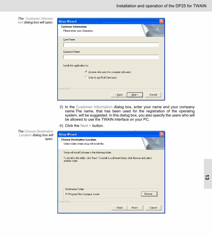
The Customer Informa-tion dialog box will open.
3) In the Customer Information dialog box, enter your name and your companyname.The name, that has been used for the registration of the operatingsystem, will be suggested. In this dialog box, you also specify the users who willbe allowed to use the TWAIN interface on your PC.
4) Click the Next > button.The Choose DestinationLocation dialog box will
open.

Installation and operation of the DP25 for TWAIN14
5) If you want the change the directory on which the TWAIN interface is to beinstalled, click the Browse... button. Select the desired directory. You shouldonly change the suggested directory if there is an important reason for it.
6) Click the Next > button.The Start Copying Files
dialog box will open.
7) To start the actual installation click the Next > button.The installation of theTWAIN Interface has
been completed. Clickthe Finish button to exit
the Setup Wizard dialogbox.
8) Click the Finish button to finalize the installation.The TWAIN Interface has now been installed.
Installation and operation of the DP25 for TWAIN15
Mounting the camera and selecting the cameradriver
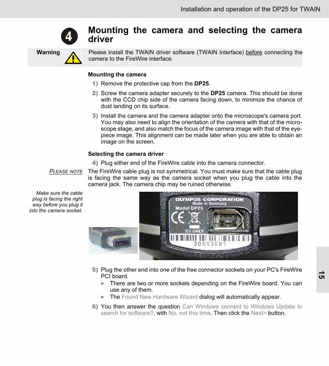
Mounting the camera1) Remove the protective cap from the DP25.
2) Screw the camera adapter securely to the DP25 camera. This should be donewith the CCD chip side of the camera facing down, to minimize the chance ofdust landing on its surface.
3) Install the camera and the camera adapter onto the microscope's camera port.You may also need to align the orientation of the camera with that of the micro-scope stage, and also match the focus of the camera image with that of the eye-piece image. This alignment can be made later when you are able to obtain animage on the screen.
Selecting the camera driver4) Plug either end of the FireWire cable into the camera connector.
PLEASE NOTE The FireWire cable plug is not symmetrical. You must make sure that the cable plugis facing the same way as the camera socket when you plug the cable into thecamera jack. The camera chip may be ruined otherwise.
Make sure the cableplug is facing the rightway before you plug it
into the camera socket.
5) Plug the other end into one of the free connector sockets on your PC's FireWirePCI board.
There are two or more sockets depending on the FireWire board. You canuse any of them.The Found New Hardware Wizard dialog will automatically appear.
6) You then answer the question Can Windows connect to Windows Update tosearch for software?, with No, not this time. Then click the Next> button.
Warning Please install the TWAIN driver software (TWAIN Interface) before connecting thecamera to the FireWire interface.

Installation and operation of the DP25 for TWAIN16
You then answer thequestion Can Windows
connect to WindowsUpdate to search for
software?, with No, notthis time.
A new dialog box entitled Found New Hardware Wizard will open.
7) Select the Install from a list or specific location (Advanced) option, and click theNext > button.
In this dialog box, selectthe Install from a list or
specific location(Advanced) option.
A new dialog box entitled Found New Hardware Wizard will open.
Installation and operation of the DP25 for TWAIN17
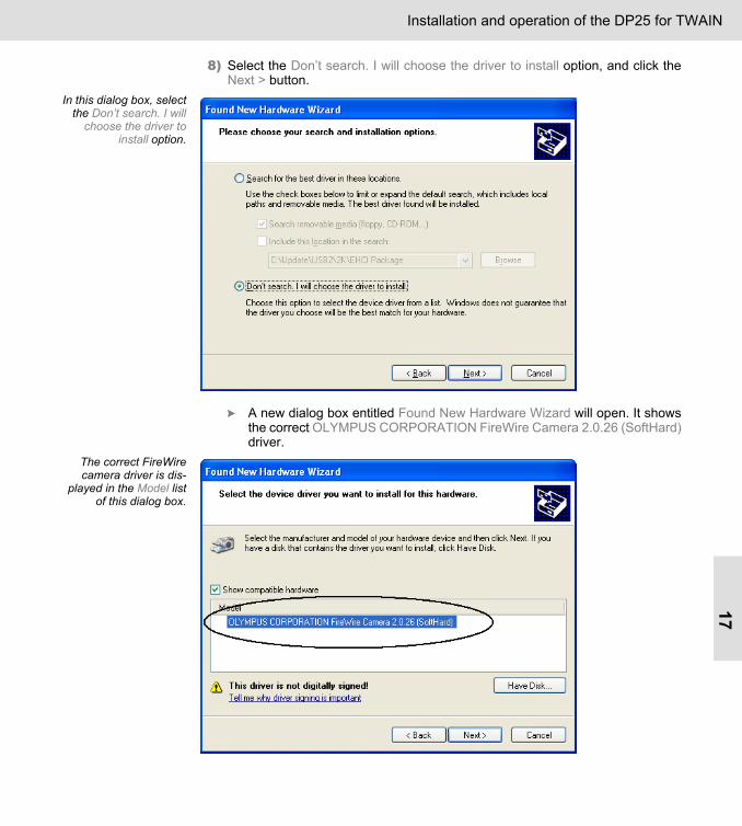
8) Select the Don’t search. I will choose the driver to install option, and click theNext > button.
In this dialog box, selectthe Don’t search. I will
choose the driver toinstall option.
A new dialog box entitled Found New Hardware Wizard will open. It showsthe correct OLYMPUS CORPORATION FireWire Camera 2.0.26 (SoftHard)driver.
The correct FireWirecamera driver is dis-
played in the Model listof this dialog box.

Installation and operation of the DP25 for TWAIN18
9) Select the OLYMPUS CORPORATION FireWire Camera 2.0.26 (SoftHard)entry in the list.
10) Click the Next > button.The next Found New Hardware Wizard dialog box will be opened in thebackground, displaying the message to wait while the Wizard installs thesoftware.
The HardwareInstallation dialog box
shown here maypop up.
11) As the information given in this dialog box is not important for the installation,simply click the Continue Anyway button.
The Hardware Installation dialog box closes.The Found New Hardware Wizard dialog box which had been in the back-ground, comes to the foreground.

Installation and operation of the DP25 for TWAIN19
12) When the camera driver for the DP25 has been selected, the following dialog
box will open.
13) Click the Finish button to end the Found New Hardware Wizard.The DP25 is now ready for use.

Installation and operation of the DP25 for TWAIN20
Starting the application programStart the application program of your choice that supports TWAIN.
The DP25 is now registered as a TWAIN device and can be selected.
Using the TWAIN InterfaceSelect the DP25 as a TWAIN source, and start the image acquisition. The exactname of the commands, used to select the TWAIN source and start the image acqui-sition, depends on the application program you are using. For more detailed informa-tion please refer to the user’s manual of the application program you are using.
The Olympus Twain window will open. This is the TWAIN Interface.The TWAIN Interface's image window displays the live-image.
The TWAIN Interface's image window displays the live-image.
Camera ControlImage Window

Installation and operation of the DP25 for TWAIN21
Acquiring imagesClick the Snap button.
The image will be transferred to the software application from which youstarted TWAIN. You can edit or save it there.
On the right-hand sideof the Olympus Twain
window, you will find allof the controls you need
to optimally adjustimages.
Adjusting the exposure timeAn automatic exposure time mode, which will already produce excellent results for agreat variety of acquisitions, is preset. Depending on the properties of your sample,however, it can become necessary to switch to the manual exposure time mode (e.g.,samples with a strongly reflecting surface).If you want to change the exposure time mode, click the option you want in the Expo-sure group (either Manual or Automatic).
Perform a white balance,Use Shift Metering Regions
Close TWAIN Interface / Acquire Image
Select exposure time mode andSet exposure time
Select resolution (and Binning)
Use focus indicator
Trim the image (subarray)
Open the Camera Settings dialog box

Installation and operation of the DP25 for TWAIN22
Manual exposuretime mode
In the manual exposure time mode you can enter the exposure time yourself. Thismode can be recommended, for example, when you want to make a variety of differ-ent acquisitions of a sample to be able to compare their brightness.
This is how you set the exposure time manuallyYou have the following options:
• Use the slide controls.• Click the plus and minus buttons. • Click the arrow buttons at the right-hand end of the edit field.• Enter an exposure time in the edit field, then press the [Enter] key.
In the manual exposuretime mode you can
select the exposure timeyourself.
The exposure time will be adjusted accordingly.If you wish, the TWAIN Interface can supply you with a benchmark, with the help ofwhich you will be able to set a suitable exposure time. To obtain this, click the Onetime Auto Exposure button.
The value set will be that which the automatic exposure time mode currentlysupplies. You can then adjust this value as you wish.
Automaticexposure time
mode
In the automatic exposure time mode, the TWAIN Interface automatically defines theexposure time for each single acquisition, so that the brightest part of the imagealways remains the same. This way you can always see the optimal image.
In automatic exposuretime mode the exposure
time is constantlychecked and updated
automatically.
This is how you set the exposure time automaticallyIf it is not already selected, click the Automatic option. You will find this option in theExposure group.
The TWAIN Interface will then calculate the exposure time automatically.PLEASE NOTE In the camera settings, maximum exposure times that limit the upwards search for
the correct exposure times, are defined. You can see these values in the CameraSettings dialog box, and can also change them there. Click the Settings button in thecamera control. Activate the DP25 > Exposure option. Then you will see the Maxi-mum exposure time group.

Installation and operation of the DP25 for TWAIN23
This is how you configure the automatic exposure timeClick the Lock Current Exposure Time button to freeze the current exposure time.
Even when you move to a completely different place on your sample whichexhibits a different brightness, the exposure time will not be adjustedaccordingly. The Lock Current Exposure Time button will remain active (also for laterimages), until you switch it off again.
Region If you want to, you can determine that the exposure time will only be measured on apart of the image, you do this in the Region field. Select an entry from the picklist.
If you have selected a spot, you have to define the Region of Interest (ROI)on which the exposure time is to be measured, in the image. Should you want to position the spot in the center of the image, you shoulduse the Center Spot on Image button for this.Select the Full Image entry, if the exposure time is to be measured on thewhole image.
Adjustment If you want to, you can select a value from the Adjustment picklist. With this valueyou can correct the automatic exposure time that has been calculated by the TWAINInterface.
To correct the automatic exposure time, switch to the live-mode and selecta value from the Adjustment list. The largest possible correction value is 4,the smallest -4. Should your images be overexposed or appear to be too bright, when youuse the automatic exposure time, select a negative correction value. Should your images be underexposed when you use the automatic expo-sure time, select a positive correction value. Select the value 0, if there is no need to correct the automatic exposure time.Test the effect of the exposure time correction in the live-image.
Installation and operation of the DP25 for TWAIN24
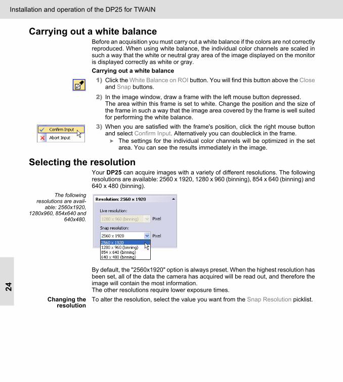
Carrying out a white balanceBefore an acquisition you must carry out a white balance if the colors are not correctlyreproduced. When using white balance, the individual color channels are scaled insuch a way that the white or neutral gray area of the image displayed on the monitoris displayed correctly as white or gray. Carrying out a white balance1) Click the White Balance on ROI button. You will find this button above the Close
and Snap buttons.
2) In the image window, draw a frame with the left mouse button depressed.The area within this frame is set to white. Change the position and the size ofthe frame in such a way that the image area covered by the frame is well suitedfor performing the white balance.
3) When you are satisfied with the frame's position, click the right mouse buttonand select Confirm Input. Alternatively you can doubleclick in the frame.
The settings for the individual color channels will be optimized in the setarea. You can see the results immediately in the image.
Selecting the resolutionYour DP25 can acquire images with a variety of different resolutions. The followingresolutions are available: 2560 x 1920, 1280 x 960 (binning), 854 x 640 (binning) and640 x 480 (binning).
The followingresolutions are avail-
able: 2560x1920,1280x960, 854x640 and
640x480.
By default, the "2560x1920" option is always preset. When the highest resolution hasbeen set, all of the data the camera has acquired will be read out, and therefore theimage will contain the most information.The other resolutions require lower exposure times.
Changing theresolution
To alter the resolution, select the value you want from the Snap Resolution picklist.

Installation and operation of the DP25 for TWAIN25
Trimming the image (subarray)If you are only interested in a part of the image on display, you can determine thatonly the data pertaining to this part of the image will be read out of the camera. Youcan define which part that is in the image. With a subarray you limit the amount of data that is exported from the camera to theTWAIN Interface. You trim the image already before the acquisition. This willincrease the frame rate, and reduce the file size of the acquired images.
This is how you set up a subarray1) Define which part of the image you are interested in. To do so, click the Set ROI
for Subarray button.The last previously defined ROI (Region of Interest) will be displayed.
2) Move the ROI to the place in the image that interests you. To do this, click in theROI, then with the left mouse button depressed, drag it to the place you want it.
3) Then adjust its size. To do this, drag the handles of the ROI. Confirm the ROIeither by doubleclicking in it, or by selecting the Confirm Input command in thecontext menu. Rightclick to open the context menu.
By doing so, you switch the subarray on. The image will then only show theimage segment you have defined.
This is how you switch off a subarrayClick the Toggle Subarray button to switch the subarray method on or off.
Focusing the sampleFocus Indicator Use the Focus Indicator to bring the sample into focus. Unlike the human eye, the
Focus Indicator calculates the sharpness of the image on a mathematical basis. The Focus Indicator enables you to control the focus settings. To begin with, youdefine a rectangular area of the image that is to be analyzed for this calculation. Themaximum contrast serves as a monitor for the sharpness in this area. The Focus Indicator has a display that indicates the relative degree of sharpness bymeans of two superimposed bars. One of these bars is red, the other blue. The redbar shows the greatest sharpness that has currently been achieved. The blue barshows the sharpness that is being achieved with the current focusing.
This is how you bring the sample into focus by using the Focus Indicator 1) Go to the place in the sample that interests you.2) Click the Toggle Focus Indicator button to switch the Focus Indicator on.
The sharpness monitor in the Focus Indicator will appear.A yellow rectangle will appear in the image. Only the pixels that are withinthis rectangle will be taken into account for the measurement of the sharp-ness of your image.

Installation and operation of the DP25 for TWAIN26
3) Change the position and size of the rectangle, so that an area of the sample thatespecially interests you will be measured. Please, make sure that the areawithin the yellow rectangle shows a high contrast portion of the sample.
4) Turn the precision focusing knob on your microscope to change the focusing.While doing this, watch the display in the Focus Indicator.
The red bar shows the greatest sharpness that has currently been achieved.The blue bar shows the sharpness that is being achieved with the currentfocusing.
5) Change the focusing on your microscope until the display is as completely blueas possible.
6) Click the Reset Focus Indicator button, to reset the sharpness monitor's bars atthe relative value of 75% for a better visualization.
PLEASE NOTE A binning that has been set does not influence the functionality of the FocusIndicator.
Zooming the imageThe image located in the TWAIN interface’s image window can be zoomed in or out.
Zooming in theimage
If your mouse is equipped with a mouse wheel, turn the mouse wheel backwards tozoom in the image. Or, press the [Crtl] key and then click the left mouse button.
Zooming out theimage
If your mouse is equipped with a mouse wheel, turn the mouse wheel forwards tozoom out the image. Or, press the [Crtl + Alt] keys simultaneously and then click theleft mouse button.
Shift Metering RegionsFor two of the DP25 functions you will need to define a rectangular image area. Oneof these functions is the Spot mode, used for the calculation of the automatic expo-sure time, the other is the Focus Indicator. The areas you have defined can, at any time, be moved or changed in size. Releasethe Shift Metering Regions button when you want to fix the position of these areas onan image.
SettingsIf you want to change the camera settings, click the Settings... button. The dialogbox's tree view offers you access to the General, Color, Adjustment, Exposure andInformation dialog boxes. Select an entry in the tree view to load the respective dialogbox.Click the Default button to return the settings in the active dialog box to their defaultvalues. The current settings will then be lost. Confirm your settings with OK.

Installation and operation of the DP25 for TWAIN27
GeneralUse this dialog box in the Camera Settings to make a variety of general camera set-tings. You can, for example, mirror the camera image, or select a pseudo color table.
The General dialog box
Mirror Select the Horizontal check box to mirror the image horizontally during acquisition.Select the Vertical check box to mirror the image vertically during acquisition.The two forms of mirroring can be combined with each other.
Image Type Select the default option "24 bit RGB Color", to acquire images of the "24-bit true-color" type.Select the "8 bit Gray Scale" option to acquire images of the "8-bit gray-value" type.
Pseudo Color You can use pseudo color tables to have images displayed in color on your monitor. By default, when you acquire images, no pseudo color tables will be used. In thiscase, the Pseudo Color > Off option is selected.Select the Use high/low pseudo color table option to have all of the pixels with a lowintensity value displayed in blue, and all of those with a high intensity value displayedin red. When you acquire this image, it will show all of the pixels in their actual color.With this pseudo color table you can immediately see if the image is well illuminated.When there are both blue and red pixels in the image, the camera's completedynamic range will be in use. If too many blue pixels can be seen, the image is under-exposed. If too many red pixels can be seen, the image is overexposed.

Installation and operation of the DP25 for TWAIN28
ColorUse this dialog box in the Camera Settings to change the camera's color settingsmanually.In this way you can change the Parameters Gain, Offset and Saturation individuallyfor each color channel. To do this, move their slide controls. R, G and B stand for theRed, Green and Blue color channels.
The Color dialog box
Gain(White Balance)
With the Gain (White Balance) value, you can weight the individual color channelsseparately. Increase, e.g. the R value, to increase the amount of red in the image.
Saturation Increase the Saturation value, if the color is too pale, and you want a better colorsaturation.

Installation and operation of the DP25 for TWAIN29
AdjustmentUse this dialog box in the Camera Settings to change the camera's contrast settingsmanually.
The Adjustment dialogbox
You will change the settings for all color channels simultaneously. If you want toaccentuate or tone down one particular color channel, use the functions in the Colordialog box.
Gamma Gamma increases, respectively lowers the image contrast, subject to the intensity Iof a pixel, according to the following equation.
with I = intensity value of the destination image, I0= the intensity value of the sourceimage. The values for Gamma vary between 0.2 and 5. Values smaller than 1 make theimage altogether darker. At the same time, the contrast in bright areas of the imagewill be increased. Values greater than 1 make the image altogether brighter. At thesame time, the contrast in dark areas of the image will be increased.
Sharpness Use the sharpen filter to increase or decrease the sharpness of the image by edgeenhancement. You change the strength of the sharpen filter by moving its slide con-trol. Values ranging from -30 to 30 are possible, whereas the default value is 0. The imagegains a smoother appearance when you use negative values and a sharper onewhen you use positive values. Raising sharpness will accentuate edges, but alsoincreases image noise. Entering a value of 0 will result in the sharpen filter having noeffect at all.
I0 I1 γ⁄=

Installation and operation of the DP25 for TWAIN30
Gain The intensity value will be multiplied by the Gain value. The image will then becomealtogether brighter.
Contrast Move the Contrast slide to change the contrast values of the image. Values smallerthan 1 lower the image contrast. Values greater than 1 enhance the image contrast.When changing the image contrast the brightest part of the image always remainsthe same. After changing the image contrast it may be that dark or bright image areasare not displayed optimally anymore. In this case use the Brightness slider to makethe whole image brighter or darker.
Brightness Use the Brightness slider, if the whole image is too bright or too dark. Values smallerthan 0 lower the image brightness. Values greater than 0 increase the image bright-ness.
Shading correctionIn the Shading Correction group you can correct two different shadings. First of all,the shading correction corrects the effect of an inhomogeneous illumination(Illumination correction). Additionally, the shading correction corrects the differentsensitivity of individual pixels on the CCD chip (Noise correction). Select the Dark option to activate the Noise Correction. Select the Flatfield option toactivate both the Illumination Correction and the Noise Correction. Select the Offoption to disable the a shading correction. Click the Edit... button to check whether correction images have already beenacquired or not. If correction images exist, you will find them listed in this dialog box.In the Image Type column the correction images used for the Noise Correction areindicated by the Dark entry, the correction images used for the Illumination Correc-tion by the Flatfield entry.
In this dialog box check,whether there are
correction images of theDark or Flatfield type, or
not.
Definition"Shading"
Every optical system with a camera and microscope creates, even when the deviceshave been set up very carefully set up, image inhomogeneities in the illumination ofthe sample. These are called shading.

Installation and operation of the DP25 for TWAIN31
The left illustrationshows an image where
the online shadingcorrection has not been
activated. In compari-son to the image on theright, one can notice the
inhomogoneities in theillumination.
For a shading correction, the shading will first be determined in order to be able tomake corrections to the acquired image. To determine which shading there is in theimage, two types of correction images will be acquired:
Dark correctionimage
The Dark correction image is an acquisition during which no light falls on the camera.Here, pixels with different brightness resulting from noise or different sensitivity ofindividual pixels on the camera chip can be corrected by the correction image. TheDark correction image is characteristic for each camera and need only be acquiredonce. It is valid for all objectives.
Flatfield correctionimage
On the Flatfield correction image the illumination of the complete optical system with-out a sample will be shown. An individual correction image must be made for everyobjective and for every resolution of your camera.
PLEASE NOTE You will need to acquire new illumination correction images every time you makechanges in your optical system. For example, when you clean your microscope,change the objectives or change the camera.
Acquiring images for the shading correction1) Open the Camera Settings > Adjustment dialog box. Click the Calibrate...
button.The Shading Correction wizard will open.

Installation and operation of the DP25 for TWAIN32
The wizard leads youstep by step through the
calibration of theshading correction.
2) If you have already acquired a Dark correction image, the Skip recording darkcorrection image check box will be automatically selected. Clear the check box, if you want to acquire a new Dark correction image.Click the Next > button.
The Dark correctionimage is an acquisition
during which no lightfalls on the camera. This
image is subtractedfrom the acquired
image.
3) Then follow the instructions given you by the software wizard. Close the lightpath selector knob on your microscope, so that no light can fall on the camera.Then click Next.
The Dark correction image will be acquired. The next dialog box of the wizard will open.

Installation and operation of the DP25 for TWAIN33
On the Flatfieldcorrection images the
illumination of the com-plete optical system
without a sample will beshown.
PLEASE NOTE The Flatfield correction image depends on the objective being used. Correspond-ingly, an individual correction image must be made for every objective. If you want touse another objective for acquiring images, you will have to acquire a new Flatfieldcorrection image.
4) Move to a position where is no sample and no scratches, and defocus.
5) Click the Next button and acquire the correction images for the currentlyselected objective.
The TWAIN interface automatically acquires the correction images for allcamera resolutions.
6) Click the Finish button to finalize the calibration and return to the Camera Set-tings > Adjustment dialog box.
Installation and operation of the DP25 for TWAIN34
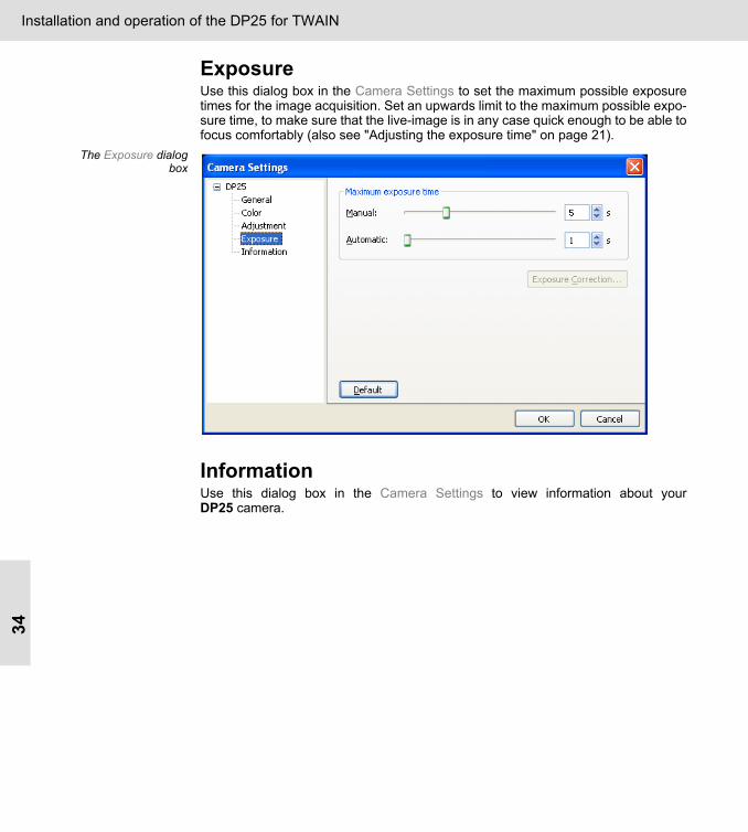
ExposureUse this dialog box in the Camera Settings to set the maximum possible exposuretimes for the image acquisition. Set an upwards limit to the maximum possible expo-sure time, to make sure that the live-image is in any case quick enough to be able tofocus comfortably (also see "Adjusting the exposure time" on page 21).
The Exposure dialogbox
InformationUse this dialog box in the Camera Settings to view information about yourDP25 camera.

Installation of the DP25 for the DP2-BSW software35
Installation of the DP25 for the DP2-BSW softwareSystem Requirements
To run your DP25 you have to use the Microsoft Windows XP operating system.Tomake proper use of your DP25, the following system requirements for your PC andthe DP2-BSW software have to be observed:
Hard- / Software Required RecommendedCPU Pentium 4, 2.4 GHz or higher
Pentium M, 1.4 GHz or higherPentium D930, 3.0 GHz, Dual Core
Pentium M, 2.6 GHz
Hard Disk Storage 5 GB or more 20 GB
Memory 512 MB or more 1024 MB
Operating system Microsoft Windows XP Pro SP 2
Ports IEEE 1394a (Firewire™)6 pin typeRequired power supply capacity 12 V, 0.2 A
Image analysisapplication
DP2-BSW

Installation of the DP25 for the DP2-BSW software36
Installation of the cameraIn order to avoid problems, you will have to follow the steps of the procedure in theorder given here.
Checking if a FireWire interface is available onyour PCIf your PC already has a FireWire interface onboard or a separate FireWire PCI boardinstalled, you do not need to install the board provided with the camera.If you are not sure whether a FireWire interface is available, open the Microsoft Win-dows Device Manager via Start > Control Panel > System > System Properties >Hardware > Device Manager... . Check that the IEEE 1394 Bus host controllers entryis there.
Check if a FireWire interface is available on your PC.
If necessary, install a FireWire PCI board.(The FireWire PCI board is included in your camera package.)
Install the DP2-BSW program on your PC.(The camera driver will also be automatically installed.)
Mount the camera on your microscope and connect it to your PC.
Select the camera driver.
Start the DP2-BSW software.

Installation of the DP25 for the DP2-BSW software37
Installing the FireWire PCI board IEEE 1394a
1) Turn off the PC and disconnect the power supply.
2) Remove the cover from the PC.
3) One PCI slot is required for the FireWire board. Insert the board into the slot.
Warning When you install the FireWire PCI board, sharp edges may cut your fingers, so takeextra care.

Installation of the DP25 for the DP2-BSW software38
FireWire PCI boardinstalled
4) Replace the cover on the PC.
5) Restart your PC.
Installing the DP2-BSW software
You can install the DP2-BSW software on your PC even if you have already installedanother software package from Olympus Soft Imaging Solutions on it.1) Insert the software protection key (dongle) into a USB port of your PC.
Warning Please install the DP2-BSW software before connecting the camera to the FireWireinterface.Should the DP25 have already been connected to the PC before the DP2-BSW soft-ware was installed, Microsoft Windows XP will have installed its own driver, which willprevent the installation of the correct driver. Please note that this does not apply to the DP20! Should you decide to use the DP20instead of the DP25, the PC will not automatically install the camera driver. Whenusing the DP20 with the DP2-BSW software, you will need to manually install thecamera driver from the CD-ROM.
Installation of the DP25 for the DP2-BSW software39
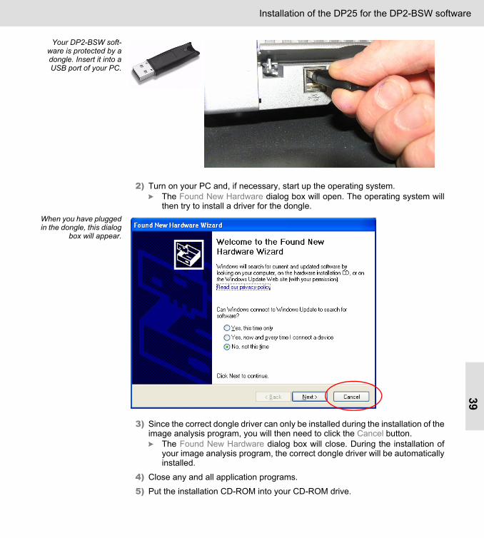
Your DP2-BSW soft-ware is protected by adongle. Insert it into aUSB port of your PC.
2) Turn on your PC and, if necessary, start up the operating system.The Found New Hardware dialog box will open. The operating system willthen try to install a driver for the dongle.
When you have pluggedin the dongle, this dialog
box will appear.
3) Since the correct dongle driver can only be installed during the installation of theimage analysis program, you will then need to click the Cancel button.
The Found New Hardware dialog box will close. During the installation ofyour image analysis program, the correct dongle driver will be automaticallyinstalled.
4) Close any and all application programs.
5) Put the installation CD-ROM into your CD-ROM drive.
Installation of the DP25 for the DP2-BSW software40
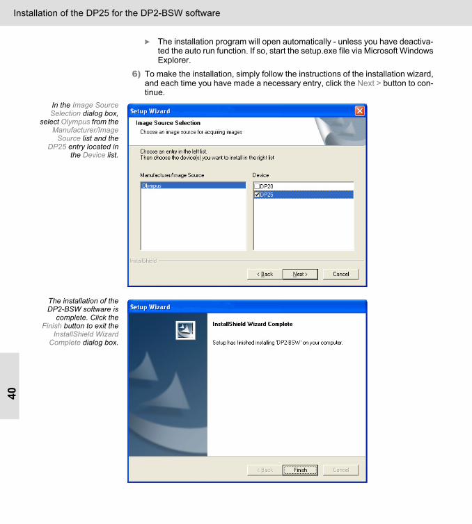
The installation program will open automatically - unless you have deactiva-ted the auto run function. If so, start the setup.exe file via Microsoft WindowsExplorer.
6) To make the installation, simply follow the instructions of the installation wizard,and each time you have made a necessary entry, click the Next > button to con-tinue.
In the Image SourceSelection dialog box,
select Olympus from theManufacturer/Image
Source list and theDP25 entry located in
the Device list.
The installation of theDP2-BSW software is
complete. Click theFinish button to exit the
InstallShield WizardComplete dialog box.

Installation of the DP25 for the DP2-BSW software41
Mounting the camera
Mounting the camera1) Remove the protective cap from the DP25.
2) Screw the camera adapter securely to the DP25 camera. This should be donewith the CCD chip side of the camera facing down, to minimize the chance ofdust landing on its surface.
3) Install the camera and the camera adapter onto the microscope's camera port.You may need to align the orientation of the camera with that of the microscopestage, and also match the focus of the camera image with that of the eyepieceimage. This alignment can be made later when you are able to obtain an imageon the screen.
4) Plug either end of the FireWire cable into the camera connector.PLEASE NOTE 5) The FireWire cable plug is not symmetrical. You must make sure that the cable
plug is facing the same way as the camera socket when you plug the cable intothe camera jack. The camera chip may be ruined otherwise.
Make sure the cableplug is facing the rightway before you plug it
into the camera socket.
6) Plug the other end into one of the free connector sockets on your PC's FireWirePCI board. There are two or more sockets depending on the FireWire board.You can use any of them.
Warning Please install the DP2-BSW software before connecting the camera to the FireWireinterface.

Installation of the DP25 for the DP2-BSW software42
Selecting the camera driverPrerequisite You have installed the DP2-BSW software and then connected the DP25 camera to
the FireWire slot.The Found New Hardware Wizard dialog will automatically appear.
1) You then answer the question Can Windows connect to Windows Update tosearch for software?, with No, not this time. Then click the Next> button.
You then answer thequestion Can Windows
connect to WindowsUpdate to search for
software?, with No, notthis time.
A new dialog box entitled Found New Hardware Wizard will open.
2) Select the Install from a list or specific location (Advanced) option, and click theNext > button.

Installation of the DP25 for the DP2-BSW software43
In this dialog box, selectthe Install from a list or
specific location(Advanced) option.
A new dialog box entitled Found New Hardware Wizard will open.
3) Select the Don’t search. I will choose the driver to install option, and click theNext > button.
In this dialog box, selectthe Don’t search. I will
choose the driver toinstall option.
Installation of the DP25 for the DP2-BSW software44
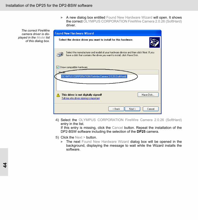
A new dialog box entitled Found New Hardware Wizard will open. It showsthe correct OLYMPUS CORPORATION FireWire Camera 2.0.26 (SoftHard)driver.
The correct FireWirecamera driver is dis-
played in the Model listof this dialog box.
4) Select the OLYMPUS CORPORATION FireWire Camera 2.0.26 (SoftHard)entry in the list.If this entry is missing, click the Cancel button. Repeat the installation of theDP2-BSW software including the selection of the DP25 camera.
5) Click the Next > button.The next Found New Hardware Wizard dialog box will be opened in thebackground, displaying the message to wait while the Wizard installs thesoftware.
Installation of the DP25 for the DP2-BSW software45
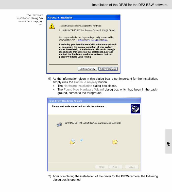
The HardwareInstallation dialog boxshown here may pop
up.
6) As the information given in this dialog box is not important for the installation,simply click the Continue Anyway button.
The Hardware Installation dialog box closes.The Found New Hardware Wizard dialog box which had been in the back-ground, comes to the foreground.
7) After completing the installation of the driver for the DP25 camera, the following
dialog box is opened.

Installation of the DP25 for the DP2-BSW software46
8) Click the Finish button to end the Found New Hardware Wizard.The DP25 is now ready for use.
Starting the DP2-BSW software

Installation of the DP25 for the DP2-BSW software47
Acquiring your first imagesPrerequisites You have successfully installed your system (DP2-BSW software, camera, and
camera driver). You would like to acquire your first images. 1) Start the DP2-BSW software.
You will automatically be in the Acquisition layout. This means that all of thesoftware controls are optimally positioned on your monitor for acquiringimages.On the right-hand edge of your screen you will find the Camera Control toolwindow. There, the Live and Snap buttons are active. You can now acquireimages and make changes in the camera settings.
LiveClick the Live button in the Camera Control tool window or use the Acquire > Livecommand.The acquired image is shown live in the document window.Use the live-mode for focussing or when arranging the camera or the sample.
SnapClick the Snap button in the Camera Control tool window or use the Acquire > Snapcommand.Use the Snap mode, to stop the live-image or to acquire a snapshot.You can edit or save the image you have acquired. The way to make image acquisi-tions is described in detail in your DP2-BSW software manual.

Installation of the DP25 for the DP2-BSW software48
Special camera functionsIn the following you will find a description of two controls that can be found in yourDP2-BSW software's Camera Control tool window when you work with the DP25.You will only find these two controls when you work with the DP25. All of the otherfunctions you will find described in detail in your DP2-BSW software's manual.
The DP2-BSWprogram's Camera
Control tool window.Here, only the twofunctions that are
specific to the DP25,"Field Update" and
"Trimming the image"will be described.
DP25 > Field Update
Trim the image (subarray)

Installation of the DP25 for the DP2-BSW software49
Trimming the image (subarray)If you are only interested in a part of the image on display, you can determine thatonly the data pertaining to this part of the image will be read out of the camera (PartialReadout). You can define which part that is in the live-image. With a subarray you limit the amount of data that is exported from the camera to yourDP2-BSW system. You trim the image already before the acquisition. The frame rateof the live-image will then increase and the size of the file in which the acquiredimages are saved will be reduced.
Setting a subarray1) First you define which part of the image you are interested in. To do so, click the
Set ROI for Subarray button.The mouse pointer will appear within the image. The last previously definedROI (Region of Interest) will be displayed.
2) Move the ROI to the place in the image that interests you. To do this, click in theROI, then with the left mouse button depressed, drag it to the place you want it.
3) Then adjust its size. To do this, drag the handles of the ROI. Confirm the ROIeither by doubleclicking in it, or by selecting the Confirm Input command in thecontext menu. Rightclick to open the context menu.
By doing so, the subarray is switched on. The live-image will then only showthe image segment you have defined.
4) Then determine whether the subarray is only to be employed for displaying thelive-image, or also for the acquisition. If it is also to be employed for the acquiredimage, clear the Live only check box.
By default, the subarray will only be employed for the live-image, that is whythe Live only check box is preselected. The display will be updated.
Field UpdateThe Field Update check box switches between a simple and an enhanced frame rate.The performance of the CPU in your PC determines the extend to which the framerate can be enhanced. Select the Field Update check box to increase the frame rate. By default, theenhanced frame rate is set. This means that the live-image will be quickly updated,even if the image information changes quickly. However, this setting will require aconsiderable amount of your CPU's performance.Clear the Field Update check box, if an enhanced frame rate is not especially impor-tant for you. This will avoid blocking more of your CPU's performance than neces-sary.

Specifications50
SpecificationsDP25 Specifications
Item SpecificationsCamera Single-CCD color camera
Image pickup device 2/3-inch color CCDTotal pixels: 5.24 million pixelsEffective pixels: 4.92 million pixelsPixel pitch: 3.4 µm (H) x 3.4 µm (V)Scanning method: Interline scanning
Cooling Natural air cooling
Recorded image sizes 2560 x 1920 (1 x 1)1280 x 960 (2 x 2)854 x 640 (3 x 3)640 x 480 (4 x 4)
Lens mount C-mount
A/D 12 bits
Exposure control* Exposure modes AutoManual
AE lock Available
One time AE Available
Exposure correction** Correction range: ± 4.0 EV. Steps: 1/3 (<2); 1/2 (>2)
Metering area Full imageCrosshair
30%1%0.1%
Metering area is freely movable.
Exposure time 200 µs to 16 s
Binning 2 x 2, 3 x 3, 4 x 4
Live frame rate**,*** Field Update 2560 (H) x 1920 (V) (1 x 1): approximately 8 fps854 (H) x 640 (V) (3 x 3): approximately 24 fps640 (H) x 480 (V) (4 x 4): approximately 32 fps
Frame Update 2560 (H) x 1920 (V) (1 x 1): approximately 4 fps1280 (H) x 960 (V) (2 x 2): approximately 8 fps854 (H) x 640 (V) (3 x 3): approximately 12 fps640 (H) x 480 (V) (4 x 4): approximately 16 fps
Color modes Color (24 bits)Gray scale ( 8 bits)
White balance mode* White Balance on ROI
Gain (White Balance)* Manual; Range: 1 to 10; Increment: 0.01
Offset (Black Balance)** Manual; Range: 0 to 100; Increment: 1
Saturation* Range: 0 to 100; Increment: 1

Specifications51
* These items can be set from the DP2-BSW V1.2 or TWAIN Interface V1.1** These items can be set from the DP2-BSW V1.2 *** The values of these items are variable depending on the exposure time settingand the PC operating
Gamma* Range: 0.2 to 5; Increment: 0.001
Sharpness filter* Range: -30 to 30; Increment: 1
Gain* Range: 1 to 5; Increment: 0.01
Contrast* Range: 0.5 to 2; Increment: 0.01
Brightness* Range: -100 to 100; Increment: 1
Focus indicator* Contrast bar
Interval recording** Recording time: 1 s to 9999 h; Fixed Interval: 1 s to 1000 h
Image file formats** TIFFBMPJPEGJPEG 2000PSDPNG
PC Interface IEEE 1394a (FIrewire)6 pin typeRequired power supply capacity for DP25: 12 V, 0.2 A
Compatible OS Microsoft Windows® XP Professional SP 2 (not compatible with x64 Edition)
Dimension and weight Camera head 86 mm (Ø) x 48 mm (H); approximately 350 g
IEEE 1394a board 121 mm (W) x 132 mm (D) x 21.5 mm (H); approximately: 60 g
IEEE 1394a cable 4.5 m length
Power consumption 12 V, 0.2 A
Operating environment Indoor useAmbient temperatures: 5 °C to 40 °C (41 °F to 104 °F)Relative humidity: 5% to 80% (without condensation)Supply voltage fluctuations by IEEE 1394a: ± 10%
Item Specifications

Help with Problems52
Help with ProblemsYou can solve most of your image problems by changing the camera settings. Toopen the Camera Settings dialog box, click the Settings button located in the CameraControl tool window. By default, you will find the Camera Control tool window on theright-hand edge of your screen.
Your image doesn't look as good as it should What should I do, when the live-image suddenly appears to be "frozen", and I receive an "Error making a snapshot" message?Check to see if the connector cable between the camera and the PC has been cor-rectly plugged-in. Should the connector be loose or not plugged in correctly, correctthis by plugging it firmly into the corresponding jack. Restart the DP2-BSW software.Should the problem still exist, contact your sales dealer.
What should I do if the image "quivers"? Quivering is caused by a frame rate that is too low. Select a lower resolution and/ora shorter exposure time. And increase the intensity.
What should I do when the image appears to be too dark?• Check on your microscope whether a diaphragm has been closed too much, or
the beam splitter has been adjusted in such a way that no light can reach thecamera.
Should your image still be too dark, then please check the following points one afterthe other. • The exposure time is possibly too short. Select a longer exposure time!
In the manual exposure time mode: Click the Settings... button in theCamera Control tool window. In the Camera Settings dialog box select theExposure entry from the tree view. In the Camera Settings > Exposuredialog box, check whether the maximum allowed exposure time has beenreached. If necessary, increase this value. To do so, move the Manual slidecontrol to the right. In the automatic exposure time mode: You should check in the Camera Set-tings > Exposure dialog box, whether the maximum allowed exposure timehas been reached. If necessary, increase the "Maximum exposure time"value. To do so, move the Automatic slide control to the right. Alternatively,you can also enter a higher value directly in the text field.
• It is possible that the exposure time correction has been set too low. In theCamera Settings > DP25 > Exposure dialog box, click the Exposure Correc-tion... button, and make sure that the exposure time correction does not liebelow 0. Should this exposure time correction show a negative value, thenplease reset it to 0.

Help with Problems53
What should I do when the image appears to be too bright?• First of all, make sure that your microscope is correctly set up (diaphragm
opening, beam splitter...).Should your image still be too bright, then please check the following points one afterthe other. • The exposure time is possibly too long. Select a shorter exposure time!
In the manual exposure time mode: In the camera control reduce the expo-sure time.In the automatic exposure time mode: The lowest possible exposure time ofthe camera (200 µs) has possibly been reached. In the Camera Settings > Adjustment dialog box set the Gamma, Sharp-ness, Gain, Contrast, and Brightness values at their resp. default values. Todo this, click the Default button.
• In the Camera Settings > DP25 > Exposure dialog box, click the ExposureCorrection... button, and make sure that the exposure time correction does notlie above 0. Set the value to 0.
What should I do when the image is monochrome?First of all, check which type of image has been set. Should the Settings > DP25 >General > Image type > 24 bit RGB color option not have been set, then set it.Should the image have been set as a "24 bit RGB color" type of image, but the imageis still monochrome, carry out a white balance with an appropriate sample.Should your image show a red tinge, despite your having carried out a white balance,this is because your lamp's color temperature is too low. Increase the lamp voltage.As a next step, you should check the following settings on your PC and its monitor.Via Control Panel > Display properties > Settings > Color Quality, set your PC's colordepth at a minimum value of 24 bits. Select, for example, the Highest (32 bit) option. Set your monitor's color temperature either via the monitor's menu navigation or viathe operating system.This is how you set the color temperature via the operating system1) Rightclick on the desktop.
2) Select the Properties option in the context menu.The Display Properties dialog box will open.
3) Select the Settings tab.
4) Click the Advanced... button.A further Display Properties dialog box will open. The appearance and func-tions of this dialog box depend on the graphics card that has been installedin your system, and on your monitor.
5) Look for a tab with either the name Color or Color Management.
6) Select a color temperature whose color impression as near as possibly matchesthat of the image in the eyepiece.

Help with Problems54
What should I do if the image is blurred and/or lacks contrast? Focus the sample visually on your microscope. Set the camera adapter so as tomake the eye piece's focal plane identical to that of your camera.Take as much care as possible to ensure that your camera and your microscopeoptics are kept clean, and that the whole system is mechanically stable.Make sure that the condenser's aperture stop is not open too wide.
"Live" and "Snap" are not activeWhat should I do when the "Live" and "Snap" buttons are inactive?This chapter is only relevant, if you use the DP25 with the DP2-BSW software. Check to see if the connector cable between the camera and the PC has been cor-rectly plugged-in. Should the connector be loose or not plugged in correctly, correctthis by plugging it firmly into the corresponding jack. Restart the DP2-BSW software.Should the problem still exist, continue with the following section.In the Device Manager, check if there is an IEEE 1394 Bus host controllers entrythere, and also that the OLYMPUS CORPORATION FireWire Camera 2.0.26 (Soft-Hard) entry is there under the Imaging devices branch. Open the Microsoft DeviceManager via Start > Control Panel > System > System Properties > Hardware >Device Manager.Should these entries not be present, the driver will then have to be installed after-wards, independently from the installation CD-ROM (see "How can I reinstall thecamera driver?" on page 54).Should the problem not have been solved even when the driver has subsequentlybeen successfully installed, check whether an Optical Path has been entered in theOptical Path dialog box. You can open the Optical Path dialog box via the Acquire >Devices > Optical Path... command. Should no entry be displayed in the upper list in the Optical Path dialog box, set oneup by using the New Wizard button. Please refer to the online help of the DP2-BSWsoftware. There you will find a step by step instruction how to set up an Optical Path. Should the problem still exist, contact your sales dealer.
When connecting the camera to the Firewire interface before installing the DP25 TWAIN driver software or the DP2-BSW soft-ware
How can I reinstall the camera driver?PLEASE NOTE Should the camera have already been connected to the PC before the TWAIN Inter-
face or the DP2-BSW software was installed, Microsoft Windows XP will haveinstalled its own driver, which will prevent the installation of the correct driver. Install-ing the DP2-BSW software afterwards or reinstalling the TWAIN interface will be ofno help! The driver will have to be installed separately.
Help with Problems55
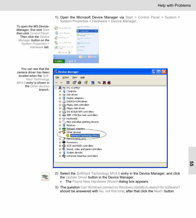
1) Open the Microsoft Device Manager via Start > Control Panel > System >System Properties > Hardware > Device Manager.
To open the MS Device-Manager, first click Startthen click Control Panel.
Then click the DeviceManager button on the
System Properties >Hardware tab.
You can see that thecamera driver has beenlocated when the Soft-
Hard TechnologyMV4.0 entry is shown in
the Other devicesbranch.
2) Select the SoftHard Technology MV4.0 entry in the Device Manager, and clickthe Update Driver button in the Device Manager.
The Found New Hardware Wizard dialog box appears.
3) The question Can Windows connect to Windows Update to search for software?should be answered with No, not this time; after that click the Next> button.

Help with Problems56
You then answer thequestion Can Windows
connect to WindowsUpdate to search for
software?, with No, notthis time.
A new dialog box entitled Found New Hardware Wizard will open.
4) Select the Install from a list or specific location (Advanced) option, and click theNext > button.
In this dialog box, selectthe Install from a list or
specific location(Advanced) option.

Help with Problems57
A new dialog box entitled Found New Hardware Wizard will open.
5) Select the Don’t search. I will choose the driver to install option.In this dialog box, select
the Don’t search. I willchoose the driver to
install option.
6) Click the Next > button.The OLYMPUS COR-PORATION FireWire
2.0.26 (SoftHard) entryis offered in the Model
list located in this dialogbox. Select it.
7) Select the OLYMPUS CORPORATION FireWire Camera 2.0.26 (SoftHard)entry in the Model list.

Help with Problems58
8) Click the Next > button.The next Found New Hardware Wizard dialog box will be opened in thebackground, displaying the message to wait while the Wizard installs thesoftware.
The HardwareInstallation dialog box
shown here maypop up.
9) As the information given in this dialog box is not important for the installation,simply click the Continue Anyway button.
You will return to the Found New Hardware Wizard dialog box.
10) Click the Next > button.

Help with Problems59
After completing the installation of the driver for the DP25 camera, thefollowing dialog box is opened.
11) Click the Finish button to end the Hardware Update Wizard assistant.
12) Switch to the Device Manager.In the tree view, you will find the OLYMPUS CORPORATION FireWireCamera 2.0.26 (SoftHard) entry under the Imaging Devices branch.
13) Restart the PC.The camera is now ready for use.

Help with Problems60
After successfullyinstalling the driver for
the DP25, theOLYMPUS CORPORA-TION FireWire Camera2.0.26 (SoftHard) entry
is displayed in theDevice Manager dialog
box. The camera is nowready for use.

Declarations of Conformity61
Declarations of ConformityWEEE declaration
Waste Electricaland Electronic
Equipment
In accordance with European Directive 2002/96/EC on Waste Electricaland Electronic Equipment, this symbol indicates that the product must notbe disposed of as unsorted municipal waste, but should be collectedseparately. Refer to your local distributor for return.
FCC complianceThis equipment has been tested and found to comply with the limits for a Class Adigital device, pursuant to Part 15 of the FCC Rules. These limits are designed toprovide reasonable protection against harmful interference when the equipment isoperated in a commercial environment. This equipment generates, uses, and canradiate radio frequency energy and, if not installed and used in accordance with theinstruction manual, may cause harmful interference to radio communications.Operation of this equipment in a residential area is likely to cause harmful interfer-ence in which case the user will be required to correct the interference at his ownexpense.
PLEASE NOTE Changes or modifications not expressly approved by the party responsible forcompliance could void the user’s authority to operate the equipment.
CE conformityThis device complies with the requirements of directive 89/336/EECconcerning electromagnetic compatibility. The CE marking indicates compliances with the above directive.

Printed in Germany DP25_E_0706
OLYMPUS CORPORATIONShinjuku Monolith, 3-1, Nishi Shinjuku 2-chome, Shinjuku-ku- Tokyo, Japan
OLYMPUS LIFE AND MATERIAL SCIENCE EUROPA GMBHPostfach 10 49 08, 20034, Hamburg, Germany
OLYMPUS AMERICA INC.3500 Corporate Parkway, Center Valley, PA18034-0610, U.S.A.
OLYMPUS SINGAPORE PTE LTD.491 B River Valley Road, #12-01/04 Valley Point Office Tower, Singapore 248373
OLYMPUS AUSTRALIA PTY. LTD.31 Gilby Road, Mt. Waverley, VIC 3149, Melbourne, Australia
OLYMPUS LATIN AMERICA, INC.5301 Blue Lagoon Drive, Suite 290, Miami, FL 33126, U.S.A.
OLYMPUS (BEIJING) SALES & SERVICE CO., LTD.12-13F, NCI Tower, A12 Jianguomenwai Avenue, Chaoyang District, Beijing, 100022, China