dp series - files.pentairliterature.comfiles.pentairliterature.com/myers/23833a148.pdf · dp series...
TRANSCRIPT
NOTE! To the installer: Please make sure you provide this manual to the owner of the equip ment or to the responsible party who maintains the system.
DP SERIESINDUSTRIAL PUMPINSTALLATION AND SERVICE MANUAL
Part # 23833A148 | © 2017 Pentair Ltd. | 06/21/17

23833A148 06/21/17 2
INSTRUCTIONSCAUTION: Positive displacement pumps must have a proper size and operable type of pressure regulating valve or pressure relief valve piped into the discharge line. This is mandatory to prevent damage to pump and piping or possible injury to personnel. Do not install any valves or shut-off devices in the bypass line from pressure regulator to tank or supply.
CAUTION: All pumps should be installed level. For mobile applications the maximum angle of intermittent operation should be no more than 5 degrees in any one direction.
CALIFORNIA PROPOSITION 65 WARNING:
This product and related accessories contain chemicals known to the State of California to cause cancer, birth defects or other reproductive harm.
It is recommended to install a pulsation dampener in the discharge line to smooth out pressure pulse. This can protect pump parts and piping for longer life and quiet operation.
BELT DRIVEWith belt drives, the pulley on both the engine and pump should be located as closely as possible to bearing to reduce bearing and shaft bending loads. Make sure that all bolts, nuts, set screws and keys are properly tightened. On multiple V-belt drives, a complete set of new belts should be installed when making a replacement.
STARTING PUMPFill pump crankcase with recommended oil to the level mark on the oil saber. Oil recommendations are covered in the lubrication section of pump instructions. Replace all drain plugs in pump and piping. Inspect tank to be sure that no foreign material is in tank or suction line. Fill tank at least half full or connect suction to water supply. Open valve (if present) in suction line. Avoid prolonged dry operation which may cause excessive wear on plunger packing. Be sure that an operating pressure gauge is located in discharge line. Use a heavy duty, liquid filled, pulsation free pressure gauge. Make sure all valves, including spray gun or nozzles, are open in discharge line. Spray gun may be anchored to discharge back into tank. Completely back off pressure adjusting device on the pressure regulating valve. Check pressure rating for pulsation dampener pressure regulator and pipe fitting to make sure working pressure is not over maximum pressure rating.
After starting, close discharge valve or spray gun slowly while watching pressure gauge to make sure relief valve or unloader is operating properly.
Adjust relief valve or unloader to desired pressure. Cycle nozzles, or gun, on and off to be sure that pressure adjustment and regulator operation is satisfactory. Nozzle capacity should not exceed 90% of pump capacity for satisfactory regulator operation. Avoid freezing by draining all water from pump and system in cold weather.
SUGGESTED MAINTENANCE SCHEDULECheck oil level – Daily
Drain and change oil – 300 hrs. Drain at operating temperature to prevent contamination from settling.
Inspect plunger packing and spacer rings – 500 hrs. Inspect frequently for leakage; each plunger packing is allowed to drip at 10 to 60 drops/min. in order to cool and lubricate packing. Replace if there is a stream leak.
Inspect valves and springs – 500 hrs. Replace if cracks and heavy wear are present.
Inspect connecting link bearing inserts – 1000 hrs. Replace at first signs of fatigue or wear to prevent damage to crankshaft.
Inspect crankshaft tapered roller bearings and plunger – 2000 hrs. Replace if there is any pitting on the seal surface or if the surface is rough. Ceramic plungers should be cleaned by soaking in muriatic acid to remove any buildup of packing material.
LUBRICATIONFill gear case with Mobilgear 630 or equivalent to 6-1/2 qts for 1000-1800 pinion rpm range and 7-1/2 qts for 600-999 rpm range. Maintain oil level at mark on oil dipstick.
Mobilgear 630 equivalent: Amoco: Permagear EP220 or Amogear EP220 Chevron: NL Gear Compound 220 Exxon: Spartan EP220 Kendall: NSMP 80w-90 Shell: Omala 220 Standard/Sohio/Boron: Gearep 80w-90 Texaco: Meropa 220
After first 30 hours of operation drain oil from gearcase (preferably drain at operating temperature), replace plug and refill crankcase with new oil. Check oil level daily and add oil as needed.

23833A148 06/21/173
ADDITIVES FOR CRANKCASE OILUse of molybdenum disulfide (MoS2) is recommended as an additive to non-synthetic oil in back geared pumps. The additive is compatible with all known oils. It is effective in reducing wear and friction that power train life may be doubled between overhauls.
SERVICEDisengage clutch, disconnect electrical leads to motor, or remove spark plug leads on engine.
REPLACING PLUNGER AND PACKING The coated plungers are very hard and ground to a super smooth surface. Special care must be taken when removing or installing.
Use wrench to unscrew front valve cap and remove. Remove packing spring by hand and top sheet metal cover. Use open wrench to grab hex part of plunger to unscrew completely off the stainless steel crosshead rod. Do not grab any other area except the hex to unscrew plunger. Pull plunger off from front cylinder bore. Use bar to push packing assembly/cartridge out by rotating pump shaft which moves crosshead rod forward. Inspect packing set and spacer ring. Check diametrical clearance between plunger and spacer ring. Replace if greater than .035" in diameter. Repeat for each cylinder.
The antiextrusion spacer ring is to be installed on the back side of each braided packing. Before installing plunger packing assembly, inspect the bore, clean out any rust or corrosion and lubricate with grease for easier installation. For models DP120, DP90, DP85, and DP 80, slide seal back ring into bore until it bottoms out and seats in place. For models DP70, DP55, DP40, and DP28, place spacers and braided packing rings into the seal cartridge. Make sure braided packing is installed in staggered position. For DP120, DP90, DP85, and DP80, place spacer and packing into bore, making sure that braided packing rings are installed in staggered position. For model DP70, DP55, DP40, and DP28, check O-ring and backup ring and replace if you see any sign of wear. Slide the seal cartridge into seal bore until it bottoms out. Place spring washer into bore. Insert coated plunger into seal bore and hand tighten to the crosshead rod. Tighten the hex until the end makes contact. The plunger shoulder must contact the end of the crosshead rod or the plunger load may strip off thread. Install packing spring. Check O-ring and backup ring in valve cap and replace if you see any sign of wear.
REMOVING AND REPLACING SEATS CENTER POST VALVESRemove the valve caps which provide access to both suction and discharge valves. Remove the stainless steel shoulder screw which serves as a valve guide and spring
retainer. Remove shoulder screw, spring retainer, spring and valve from the pump fluid end.
Assemble stud, retainer and three screws by inserting screw heads through holes in valve seat. Rotate retainer to the right until heads catch and secure in place by screwing stud firmly. Place plate over stud, screw on nut and torque slowly with wrench until seat breaks loose.
Suction valve seats are removed as above, except two stud lengths are joined using coupling.
To replace, inspect tapered valve seat bore in fluid end for rust and wipe out excess with a rag. Place a new lower seat in tapered hole. Drive lower seat firmly into place and repeat for upper seat being sure to also inspect the tapered bore for rust.
Reassemble valve, spring and spring retainer and confirm that springs are in correct location. The heavier spring is installed on upper or discharge valve. Be sure that shoulder screw is bottomed in valve seat. This screw is furnished with a Nylock locking pellet to prevent accidental loosening of screw. Also be certain that the valve disc is installed on the valve with the flat face down. Inspect O-rings and backup rings on valve caps. Replace if O-rings show signs of wear.
REPLACING CROSSHEAD ROD OIL SEALSThe rod seal assembly contains two seals and two oil seals with lips facing the power end. The oil seal can be replaced without taking the fluid end off by taking the front cylinder head valve caps off and unscrewing and pushing the ceramic plunger towards the front to allow access for oil seal housing. Unscrew two Allen screws and place into the other two tapped holes. Gradually screw them in to push oil seal housing off the retainer. After assembling new seals in oil seal housing, an assembly thimble should be used on the end of the crosshead rod for sliding oil seal housing back into retainer. Check gasket and replace if damaged. The thimble should be machined from high carbon steel and polished on the exterior to reduce possibility of seal lip damage.
REMOVING CRANKSHAFT AND PINION SHAFTRemove front valve cap and plungers. Remove connecting link caps and move the link-crosshead assembly as far forward as possible. Secure separation of the crankshaft gear and gear case so that crankshaft will be held in place against pinion shaft. Remove both crankshaft bearing caps. Hold crankshaft at ring gear and left-hand link journal to prevent dropping into bearing bores and remove from gear case by moving crankshaft to the right until left end can be swung free.

23833A148 06/21/17 4
Tap the end of the pinion shaft extension to remove the bearing cup at the opposite end. After removing pinion shaft, the remaining bearing cup can be removed by gently tapping against the peripheral edge of the cup with a brass rod.
REPLACING PINION SHAFT AND SHIMMING BEARINGS After installing the link-crosshead assemblies and moving them toward the fluid end as far as possible, tap the right-hand pinion shaft bearing cup into position using the bearing cap. Make sure that the spacer is properly seated on drive end of pinion shaft. The curve side should match the fillet radius of pinion shaft. Place pinion shaft in position and tap left-hand bearing cup into place.
Cover the shaft keyway to protect lip of oil seal. Slide on the open bearing cap with a .030" shim. Tighten the four cap screws to recommended torque.
Install other cap using total shim thickness. Tighten cap screws holding pinion or crankshaft caps to gear case. Rotate pinion shaft back and forth, applying about 15 lbs. axial force to properly seat tapered rollers. Measure end-play by using an indicating gauge.
Subtract recommended end-play (.005"–.009") from actual end-play. This is the amount of shim that must be removed. After excess shim thickness has been removed, replace caps and retighten cap screws. Measure end-play, and if end-play is not within limits recommended, add or subtract shims as required.
REPLACING PINION SHAFT AND SHIMMING BEARINGS ON HYDRAULIC DRIVEN PUMPSPress bearing cones onto both ends of the pinion shaft, being sure bearing seats completely against stop on shaft. Place pinion and bearing cone assembly into the crankcase, positioning the pinion gear over the crankshaft gear. Carefully press bearing cups into both sides of the crankcase. Tap cups until bearing cups and cones are completely together and pinion is in the proper location in the crankcase. Press shaft seal into cap, bearing and seal plate. Be sure both caps are installed with the lip towards the center of the pump. Install right bearing cap with two .003" thick shims and tighten cap screws. Install left bearing cap with one .015" thick and one .003" thick shim and tighten the eight socket head cap screws to the recommended torque. Rotate pinion shaft back and forth, applying about 15 lbs. axial force to properly seat the tapered rollers. Measure end-play by using an indicating gauge. Subtract recommended end-play (.005"–.009") from actual end-play. This is the amount of shim that must be removed. After excess shim thickness has been removed, replace left cap and retighten cap screws. Measure end-play again and repeat if necessary.
REPLACING CRANKSHAFT AND SHIMMING BEARINGSPress the bearing cups into the caps. Place one cap into position on the right side with cap screws engaged about one turn. Install crankshaft left end first, and push both bearing caps into place. Extreme care should be exercised to avoid damage to gear teeth, bearings, and link journals.
For quiet operation and long life, the crankshaft and bearings must be installed with .003" to .005" preload. To adjust, loosen the four cap screws on the pinion shaft bearing cap.
Place about a .045" shim on the right crankshaft bearing cap, and tighten the five cap screws. Install the left cap without shims and secure with two cap screws at 13 ft/lbs and rotate the crankshaft. Retorque the cap screws. Repeat three times to properly seat the tapered roller bearings. Measure (adjacent to the cap screws) the shim gap remaining between the bearing cap and the gear case. The required shim thickness for this cap is equal to the average gap measurement plus .022". Insert correct shim thickness under left bearing cap and tighten cap screws. Install connecting links and caps, then torque cap screws to 40 ft/lbs.
IMPORTANT – Check for adequate side clearance of links on crankshaft. Some shims must be moved from one end to the other until sideways movement of all links can be seen.
Check torque of cap screws on all bearing caps.
RECONDITIONED CRANKSHAFTSWhen the crank throws are slightly damaged, they can sometimes be reconditioned for further use. This can be done by sandpapering and polishing until all ridges are completely removed. The final polishing operation should be with very fine emery cloth. If the surface is badly damaged, the crankshaft can often be salvaged by “metalizing” the crank throw, regrinding and polishing to the original diameter.
SERVICING CONNECTING LINKSThe connecting rod link is furnished with replaceable split sleeve bearing inserts at the crank throw. Do not attempt to re-fit connecting links to the crankshaft bearings by filing or grinding the mating faces of the link cap where it contacts the link. Always be sure that the proper side of the link is placed upward when attaching it to the crankshaft. The upper side contains an oil hole at the crosshead end of the link. This oil hole must be up to allow proper oil feeding to the crosshead pin bushing. The wrist pin is press-fitted into the crosshead and slip-fitted through the bronze bushing. Use arbor press to force in the wrist pin, checking to see if the link is free to rotate
23833A148 06/21/175
after the wrist pin is pressed in. Verify that both sides of the wrist pin do not protrude beyond the crosshead.
The crosshead end of the connecting link is fitted with a bronze bushing. New replacement link bushings are reamed to the proper size for immediate installation. If only the bushing is replaced, it may be necessary to ream the new bushing to the proper inside diameter after it is pressed into the link. When placing the bushing on the link, be sure that the oil holes in the bushing and link are in line after the bushing is pressed into position.
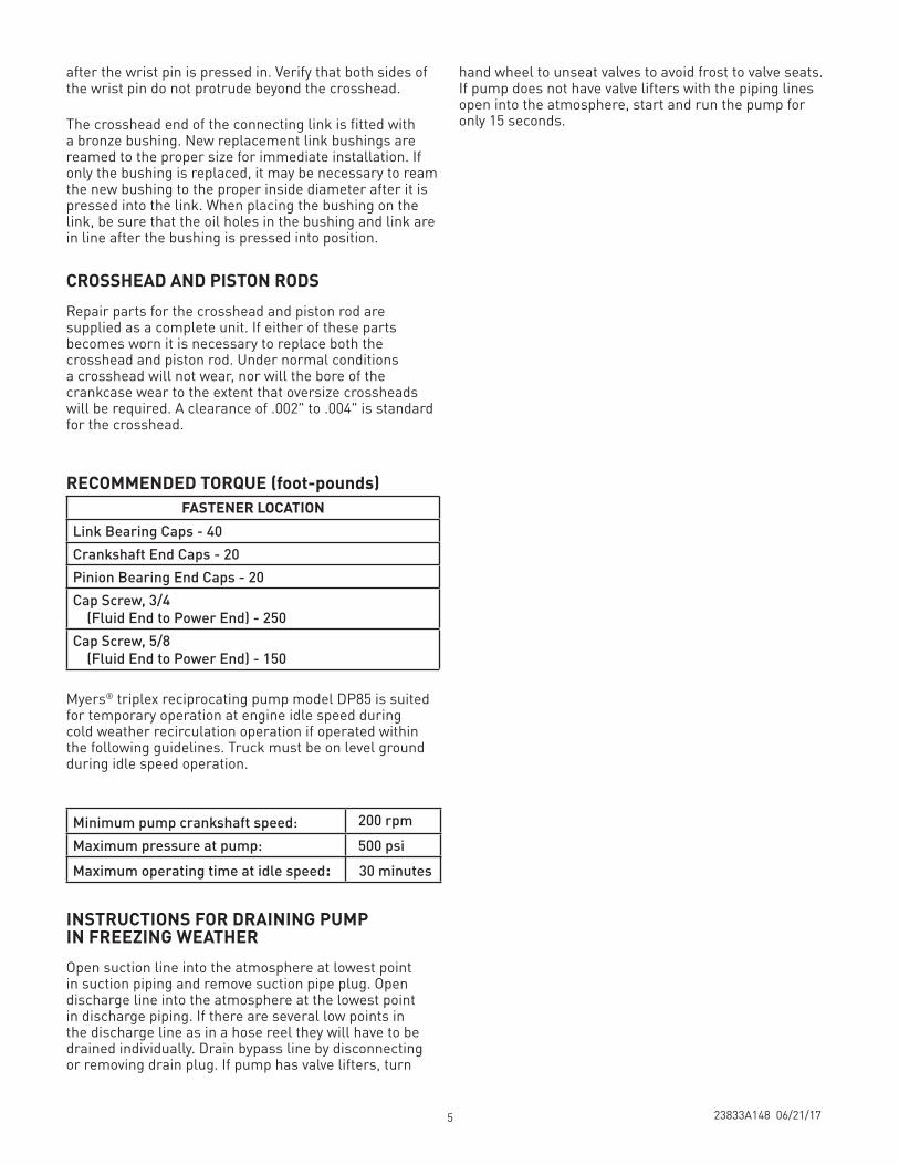
CROSSHEAD AND PISTON RODSRepair parts for the crosshead and piston rod are supplied as a complete unit. If either of these parts becomes worn it is necessary to replace both the crosshead and piston rod. Under normal conditions a crosshead will not wear, nor will the bore of the crankcase wear to the extent that oversize crossheads will be required. A clearance of .002" to .004" is standard for the crosshead.
Myers® triplex reciprocating pump model DP85 is suited for temporary operation at engine idle speed during cold weather recirculation operation if operated within the following guidelines. Truck must be on level ground during idle speed operation.
INSTRUCTIONS FOR DRAINING PUMP IN FREEZING WEATHEROpen suction line into the atmosphere at lowest point in suction piping and remove suction pipe plug. Open discharge line into the atmosphere at the lowest point in discharge piping. If there are several low points in the discharge line as in a hose reel they will have to be drained individually. Drain bypass line by disconnecting or removing drain plug. If pump has valve lifters, turn
RECOMMENDED TORQUE (foot-pounds)FASTENER LOCATION
Link Bearing Caps - 40Crankshaft End Caps - 20Pinion Bearing End Caps - 20Cap Screw, 3/4 (Fluid End to Power End) - 250Cap Screw, 5/8 (Fluid End to Power End) - 150
Minimum pump crankshaft speed: 200 rpmMaximum pressure at pump: 500 psiMaximum operating time at idle speed: 30 minutes
hand wheel to unseat valves to avoid frost to valve seats. If pump does not have valve lifters with the piping lines open into the atmosphere, start and run the pump for only 15 seconds.

23833A148 06/21/17
Explanation of the Service Chart
1. Pump priming is usually not necessary when the pump is installed correctly. However, there are certain conditions which may make it necessary to prime the pump to get the pumping action started. Priming will be required when it is impossible for the piston to displace the air in the pump and replace it with water. This could be caused by a high suction lift, the valves being stuck on the seat or by valves sticking due to extreme corrosion. A pump will not prime readily if someone has tampered with the valve springs causing them to exert undue pressure of the valve plates against the valve seats.
2. A gate valve is sometimes installed in the suction line between a tank or pressure line, and pump sediment chamber, to shut off the supply source for cleaning the sediment chamber or for pump repairs. If this valve is partially or fully closed, it will interfere with the flow of water to the pump suction. This also may cause severe knocking and vibration of the pump because the water cannot flow into the cylinder cavities fast enough.
3. A sediment chamber should be installed in the suction line between the gate valve and the pump suction. The strainers in these sediment chambers are to allow a free flow of liquid to the pump. If the strainers become severely clogged, they will completely stop the flow of liquid to the pump.
4. Any piston pump operating at a high pressure will not perform properly or quietly if a mixture of air and water is allowed to enter the pump suction. A small air leak in the suction line will cause the pump to knock and vibrate excessively by allowing the pump to draw a certain amount of water mixed with air on each stroke of the piston. A large air leak will cause the pump to lose prime after which it cannot be reprimed until the air leak is stopped. Air leaks may occur at the joints of the suction line piping, at the gate valve in the suction line, at the gasket sealing the cap on the sediment chamber, by a crack in the suction wall of the cylinder body, or by air drawing past the packing on the suction stroke if the packing is badly worn.
THE PUMP MUST BE INSTALLED WITH A PRESSURE RELIEF VALVE IN DISCHARGE LINE
TROUBLESHOOTING Pump fails to build pressure with discharge closed Failure to hold pressure with discharge open Pump is noisy Pump gets hot Pressure gauge shows abnormal fluctuation
POSSIBLE CAUSE OF PROBLEM 1. Pump not primed X 2. Valve closed in suction line X X 3. Suction line or sediment chamber clogged X X X 4. Air leak in suction line X X X 5. Pressure regulator valve badly worn or not properly adjusted X X 6. Broken valves or springs X X X 7. Pump packing or valves badly worn X X X 8. Pressure regulator bypassed by open #1 valve X X 9. Pump cylinder body cracked X X X10. Water in crankcase X11. Worn connecting link inserts or wrist pin bushings X X12. Lack of oil in crankcase X X13. Foaming mixture in tank X X X14. Regulator plunger sticking X15. Foreign matter under pump valve X X X16. Loose piston rod X17. Improper preload of crankshaft bearings X X
6
23833A148 06/21/17
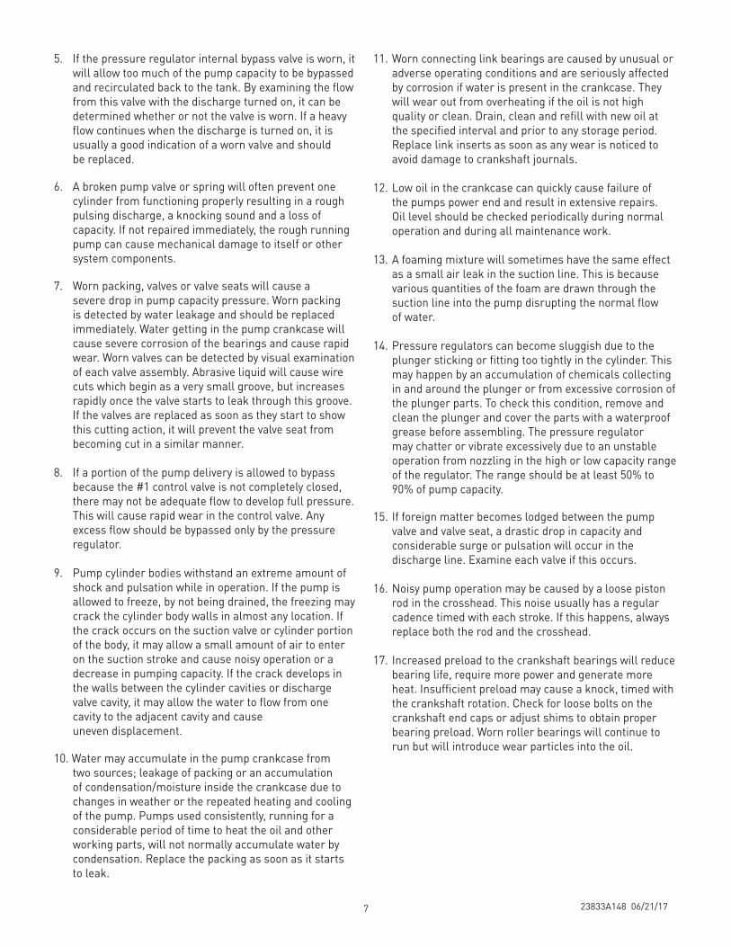
5. If the pressure regulator internal bypass valve is worn, it will allow too much of the pump capacity to be bypassed and recirculated back to the tank. By examining the flow from this valve with the discharge turned on, it can be determined whether or not the valve is worn. If a heavy flow continues when the discharge is turned on, it is usually a good indication of a worn valve and should be replaced.
6. A broken pump valve or spring will often prevent one cylinder from functioning properly resulting in a rough pulsing discharge, a knocking sound and a loss of capacity. If not repaired immediately, the rough running pump can cause mechanical damage to itself or other system components.
7. Worn packing, valves or valve seats will cause a severe drop in pump capacity pressure. Worn packing is detected by water leakage and should be replaced immediately. Water getting in the pump crankcase will cause severe corrosion of the bearings and cause rapid wear. Worn valves can be detected by visual examination of each valve assembly. Abrasive liquid will cause wire cuts which begin as a very small groove, but increases rapidly once the valve starts to leak through this groove. If the valves are replaced as soon as they start to show this cutting action, it will prevent the valve seat from becoming cut in a similar manner.
8. If a portion of the pump delivery is allowed to bypass because the #1 control valve is not completely closed, there may not be adequate flow to develop full pressure. This will cause rapid wear in the control valve. Any excess flow should be bypassed only by the pressure regulator.
9. Pump cylinder bodies withstand an extreme amount of shock and pulsation while in operation. If the pump is allowed to freeze, by not being drained, the freezing may crack the cylinder body walls in almost any location. If the crack occurs on the suction valve or cylinder portion of the body, it may allow a small amount of air to enter on the suction stroke and cause noisy operation or a decrease in pumping capacity. If the crack develops in the walls between the cylinder cavities or discharge valve cavity, it may allow the water to flow from one cavity to the adjacent cavity and cause uneven displacement.
10. Water may accumulate in the pump crankcase from two sources; leakage of packing or an accumulation of condensation/moisture inside the crankcase due to changes in weather or the repeated heating and cooling of the pump. Pumps used consistently, running for a considerable period of time to heat the oil and other working parts, will not normally accumulate water by condensation. Replace the packing as soon as it starts to leak.
11. Worn connecting link bearings are caused by unusual or adverse operating conditions and are seriously affected by corrosion if water is present in the crankcase. They will wear out from overheating if the oil is not high quality or clean. Drain, clean and refill with new oil at the specified interval and prior to any storage period. Replace link inserts as soon as any wear is noticed to avoid damage to crankshaft journals.
12. Low oil in the crankcase can quickly cause failure of the pumps power end and result in extensive repairs. Oil level should be checked periodically during normal operation and during all maintenance work.
13. A foaming mixture will sometimes have the same effect as a small air leak in the suction line. This is because various quantities of the foam are drawn through the suction line into the pump disrupting the normal flow of water.
14. Pressure regulators can become sluggish due to the plunger sticking or fitting too tightly in the cylinder. This may happen by an accumulation of chemicals collecting in and around the plunger or from excessive corrosion of the plunger parts. To check this condition, remove and clean the plunger and cover the parts with a waterproof grease before assembling. The pressure regulator may chatter or vibrate excessively due to an unstable operation from nozzling in the high or low capacity range of the regulator. The range should be at least 50% to 90% of pump capacity.
15. If foreign matter becomes lodged between the pump valve and valve seat, a drastic drop in capacity and considerable surge or pulsation will occur in the discharge line. Examine each valve if this occurs.
16. Noisy pump operation may be caused by a loose piston rod in the crosshead. This noise usually has a regular cadence timed with each stroke. If this happens, always replace both the rod and the crosshead.
17. Increased preload to the crankshaft bearings will reduce bearing life, require more power and generate more heat. Insufficient preload may cause a knock, timed with the crankshaft rotation. Check for loose bolts on the crankshaft end caps or adjust shims to obtain proper bearing preload. Worn roller bearings will continue to run but will introduce wear particles into the oil.
7

23833A148 06/21/17
*NOTE: When purchasing the crankshaft or pinion on units built prior to 07/12, both items will need to be replaced due to an improvement in design.
Item Description Qty. Eng. No1 CASE, GEAR 1 04625E100
2* SHAFT, PINION 1 27938B0403 SHIM, GREEN, .003" THK. 4 05863A0244 SHIM, PINK, .015" THK. 2 05863A0235 CONE, BEARING 2 05674A0206 CUP, BEARING 2 05675A0197 CAP, BEARING & SEAL 2 04741B0108 SEAL, OIL 2 05710A0469 SCREW, CAP, SOCKET HEAD GRADE 8
5/16-24UNF X 1" LONG (TORQUE 15 LB./FT.)16 06106A048
Item Description Qty. Eng. No1 CASE, GEAR 1 04625E001K2 GASKET, LID 1 06201C000
SCREW, CAP, 5/16"-18 UNC x 1/4", STEEL 8 19100A0053 LID 1 04561B0004 NIPPLE, SPECIAL VENT 1 17995A0005 CAP, PIPE 1 05737A0026 GAUGE, OIL, WITH O-RING 1 7206-0094-00K7 SHAFT, PINION* 1 27938B020K
SPACER 1 20164B022ASHIM, PLASTIC, .003" 4 05231A074SHIM, PLASTIC, .015" 4 05231A075CONE, BEARING 2 05674A013CUP, BEARING 2 05675A009CAP, OPEN 1 04563A001CAP, CLOSED 1 04741B001OIL SEAL 1 05710A017SCREW, CAP, 3/8"-16 UNC x 1", STEEL 18 19101A009WASHER, SEAL 18 14946A003CRANKSHAFT* 1 27937C022KCRANKSHAFT, DP85-20 27937C044KCONE, BEARING 2 05674A021CUP, BEARING 2 05675A013CAP, BEARING 2 04624B004SHIM, PLASTIC, 6-7/32" x 5-1/32" x .003" 6 05068A018SHIM, PLASTIC, 6-7/32" x 5-1/32" x .015" 6 05068A016O-RING, 5" I.D., 5-1/8" O.D., 1/16" THICK 2 05876A098
8 CROSSHEAD 3 24956B0009 LINK, DUCTILE IRON 3 17042C002
BUSHING 3 B01619A000KSCREW, CAP 6 19103A016
10 BEARING, TWO HALVES 3 15245A101K11 WRIST PIN 3 M01525A00112 HOUSING, OIL SEAL 3 24959A00013 OIL SEAL 6 22835A00314 RETAINER, OIL SEAL HOUSING 3 24958A000
SCREW, ALLEN 6 06106A034GASKET, SEAL HOUSING 3 05059A434GASKET, RETAINER 3 05059A058
15 PLUG, PIPE, MAGNETIC 1 17481A002SCREW, SOCKET HD., 3/4"-10 UNC X 3", GR 5 4 06106A038LOCKWASHER 4 05454A003SCREW, CAP, 5/8"-11 UNC X 2", STEEL, GR 5 4 19105A008SPRING 3 M01643A000
DP SERIES PLUNGER PUMP
PARTS LIST
POWER END PARTS 24960F101 L.H. & 24960F100 R.H. HYDRAULIC DRIVE COMPONENTS
8

23833A148 06/21/17
Item Description Qty. Eng. No Model16 BODY, FLUID END A (L.P.) 1 24961F000K DP120-12, DP90-18, DP85-20, DP80-20, DP70-22
BODY, FLUID END B (H.P.) 1 24961F001K DP55-28BODY, FLUID END C (V.H.P.) 1 24961F003 DP28-55, DP40-38
17 CAP, VALVE 6 24797A000 ALL MODELSO-RING 6 05876A168 ALL MODELSRING, BACKUP 6 18753A007 ALL MODELSCAP, VALVE, SUCTION 3 24797A002 DP28-55, DP40-38O-RING 3 05876A221 DP28-55, DP40-38RING, BACKUP 3 18753A010 DP28-55, DP40-38
18 VALVE, Acetal 3 18834A003 ALL MODELS19 SEAT, SUCTION VALVE F.E.A 3 24796A000 DP120-12, DP90-18, DP 85-20, DP80-20, DP70-22
F.E.B 3 24796A002 DP55-28F.E.C 3 24796A012 DP28-55, DP40-38
20 SEAT, DISCHARGE VALVE F.E.A 3 24796A001 DP120-12, DP90-18, DP 85-20, DP80-20, DP70-22F.E.B 3 24796A003 DP55-28F.E.C 3 24796A013 DP28-55, DP40-38
21 SPRING, SUCTION VALVE 3 11829A000 ALL MODELS22 SPRING, DISCHARGE VALVE 3 11829A001 ALL MODELS23 RETAINER, SPRING 6 18833A001 ALL MODELS24 SCREW, CAP, THRD. LOCK 3 18832A002 ALL MODELS25 SPRING, PACKING 3 24799A000 DP120-12
SPRING, PACKING 3 24799A001 DP90-18, DP 85-20, DP80-20, DP70-22SPRING, PACKING 3 24799A002 DP55-28, DP40-38, DP28-55
26 PLUNGER, COATED (2-5/8" D.) 3 24798B020 DP120-12(2-1/4" D.) 3 24798B021 DP90-18, DP 85-20(2-1/8" D.) 3 24798B022 DP80-20(2" D.) 3 24798B023 DP70-22(1-3/4" D.) 3 24798B024 DP55-28(1-1/2" D.) 3 24798B025 DP40-38(1-1/4" D.) 3 24798B026 DP28-55
27 RING, SEAL BACK (2-5/8") 3 24954A000 DP120-12(2-1/4") 3 24954A001 DP90-18, DP 85-20(2-1/8") 3 24954A002 DP80-20CARTRIDGE, SEAL (2") 3 24953B000 DP70-22(1-3/4") 3 24953B001 DP55-28(1-1/2") 3 24953B002 DP40-38(1-1/4") 3 24953B003 DP28-55
28 O-RING, SEAL CARTRIDGE (2) 3 05876A167 DP70-22(1-3/4, 1-1/2, 1-1/4) 3 05876A166 DP55-28, DP40-38, DP28-55
29 RING, BACKUP, SEAL CARTRIDGE (2) 3 18753A006 DP70-22(1-3/4, 1-1/2, 1-1/4) 3 18753A005 DP55-28, DP40-38, DP28-55
30 PACKING, PLUNGER 2-5/8 (4/SET) 3 24962A001 DP120-122-1/4 (3/SET) 3 24962A002 DP90-18, DP 85-202-1/8 (3/SET) 3 24962A003 DP80-202 (3/SET) 3 24962A004 DP70-221-3/4 (3/SET) 3 24962A005 DP55-281-1/2 (3/SET) 3 24962A006 DP40-381-1/4 (3/SET) 3 24962A007 DP28-55
31 WASHER, SPRING 2-5/8 3 24955A000 DP120-122-1/4 3 24955A001 DP90-18, DP 85-202-1/8 3 24955A002 DP80-202 3 24955A003 DP70-221-3/4 3 24955A004 DP55-281-1/2 3 24955A005 DP40-381-1/4 3 24955A009 DP28-55 LID, CYLINDER 1 M01520A000 ALL MODELSSLINGER 3 05059A263 ALL MODELSPLUG, PIPE, 3" 2 03210A000 ALL MODELSPLUG, PIPE, 1" 3 05022A043 ALL MODELSPLUG, PIPE, 1/4 NPT 4 05022A092
FLUID END PARTS - DP SERIES
9

23833A148 06/21/17
DP90-18DP85-20
(2 1/4 Ø)
DP55-28(1 3/4 Ø)
DP40-38(1 1/2 Ø)
DP28-55(1 1/4 Ø)
DP70-22(2 Ø)
DP120-12(2 1/4 Ø)
DP80-20(2 1/4 Ø)
31
30
2731 30
27 30
3129
28
27 30
31 27
28
2931
27
30
28
29
31 28
29
30
27
15
9
1118
14
12
27
19
21
25
20
18
22
24
17
23
16
26 13
7
45
3
10
6
2
30
31
DIMENSIONS, S.A.E. "C" FACE MOUNTING
10

THIS PAGE INTENTIONALLY LEFT BLANK

1101 MYERS PARKWAY ASHLAND, OHIO, USA 44805 855-274-8948
WWW.FEMYERS.COM
Warranty Rev. 12/13
STANDARD LIMITED WARRANTYCENTRIFUGAL & RECIPROCATING PUMPS
Pentair Myers® warrants its products against defects in material and workmanship for a period of 12 months from the date of shipment from Pentair Myers or 18 months from the manufacturing date, whichever occurs first – provided that such products are used in compliance with the requirements of the Pentair Myers catalog and technical manuals.
During the warranty period and subject to the conditions set forth, Pentair Myers, at its discretion, will repair or replace to the original user, the parts that prove defective in materials and workmanship. Pentair Myers reserves the right to change or improve its products or any portions thereof without being obligated to provide such a change or improvement for prior sold and/or shipped units.
Seals, piston cups, packing, plungers, liners and valves used for handling clear, fresh, nonaerated water at a temperature not exceeding 120ºF are warranted for ninety days from date of shipment. All other applications are subject to a thirty day warranty. Accessories such as motors, engines and auxiliary equipment are warranted by the respective manufacturer and are excluded in this standard warranty. Under no circumstance will Pentair Myers be responsible for the cost of field labor, travel expenses, rented equipment, removal/reinstallation costs or freight expenses to and from the factory or an authorized Pentair Myers service facility.
This limited warranty will not apply: (a) to defects or malfunctions resulting from failure to properly install, operate or maintain the unit in accordance with the printed instructions provided; (b) to failures resulting from abuse, accident or negligence; (c) to normal maintenance services and parts used in connection with such service; (d) to units that are not installed in accordance with applicable local codes, ordinances and good trade practices; (e) if the unit is moved from its original installation location; (f) if unit is used for purposes other than for what it is designed and manufactured; (g) to any unit that has been repaired or altered by anyone other than Pentair Myers or an authorized Pentair Myers service provider; (h) to any unit that has been repaired using non factory specified/OEM parts.
Warranty Exclusions: PENTAIR MYERS MAKES NO EXPRESS OR IMPLIED WARRANTIES THAT EXTEND BEYOND THE DESCRIPTION ON THE FACE HEREOF. PENTAIR MYERS SPECIFICALLY DISCLAIMS THE IMPLIED WARRANTIES OF MERCHANTABILITY AND FITNESS FOR ANY PARTICULAR PURPOSE.
Liability Limitation: IN NO EVENT SHALL PENTAIR MYERS BE LIABLE OR RESPONSIBLE FOR CONSEQUENTIAL, INCIDENTAL OR SPECIAL DAMAGES RESULTING FROM OR RELATED IN ANY MANNER TO ANY PENTAIR MYERS PRODUCT OR PARTS THEREOF. PERSONAL INJURY AND/OR PROPERTY DAMAGE MAY RESULT FROM IMPROPER INSTALLATION. PENTAIR MYERS DISCLAIMS ALL LIABILITY, INCLUDING LIABILITY UNDER THIS WARRANTY, FOR IMPROPER INSTALLATION. PENTAIR MYERS RECOMMENDS INSTALLATION BY PROFESSIONALS.
Some states do not permit some or all of the above warranty limitations or the exclusion or limitation of incidental or consequential damages and therefore such limitations may not apply to you. No warranties or representations at any time made by any representatives of Pentair Myers shall vary or expand the provision hereof.