Zone sculpting using partitioned electrokinetic injectionsMax Narovlyansky and George M. WhitesidesDepartment of Chemistry and Chemical Biology, Harvard University, 12 Oxford St., Cambridge,Massachusetts 02138, USA
Todd M. Squiresa�
Department of Chemical Engineering, University of California, Santa Barbara, California 93106, USA
�Received 14 September 2007; accepted 22 October 2007; published online 14 November 2007�
We describe a general and versatile method to sculpt low-dispersion, high-fidelity sample zones inmicrofluidic devices for high resolution electrokinetic separations. In a simple channel intersection,microfabricated partitions reduce each channel’s permittivity to transverse electric fields, yetmaintain their permeability to parallel fields. The resulting anisotropy effectively confines fields tothe intersection, thus sculpting the injected plug. We demonstrate by injecting narrow yet symmetricsample zones in a poly�dimethylsiloxane� microfluidic device. This simple geometric strategy forsculpting the field and flow lines does not depend on the device material or analyte/electrolyteproperties, and is limited in scale only by fabrication capabilities. © 2007 American Institute ofPhysics. �DOI: 10.1063/1.2814031�
Electrophoretic separations are a workhorse of analyticalchemistry. For two species to be clearly resolved in capillaryelectrophoresis, their corresponding bands must travel suffi-ciently far that they no longer overlap, but must do soquickly enough that dispersion does not blur the separation.In addition to molecular diffusion, various factors workagainst the separation process to limit the ultimate resolu-tion: Taylor �convective� dispersion in non-plug flow, Jouleheating, intermolecular interactions, and adsorption to walls.1
Even if such dispersive effects were entirely absent, how-ever, the resolution of the separation could not exceed thatgiven by the width of the initial plug. Reducing the width ofthis plug, therefore, may decrease the length of time requiredfor separation, decrease the size of the separation device, andincrease the ultimate resolution of the separation.
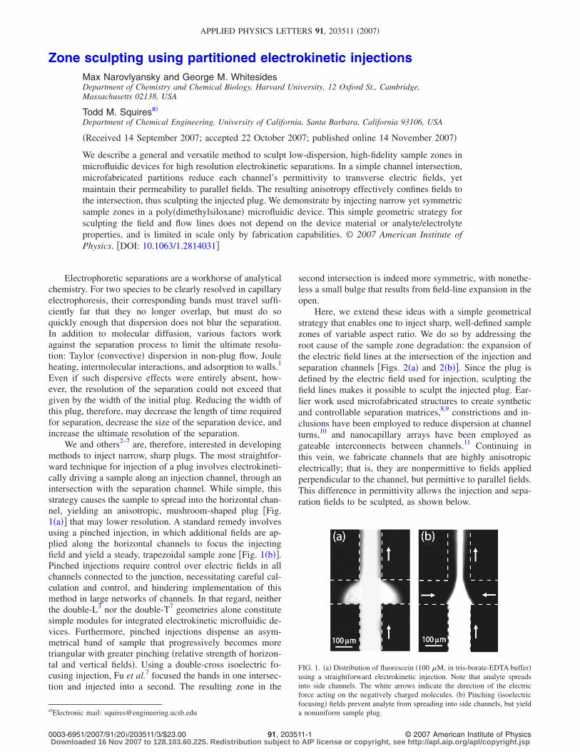
We and others2–7 are, therefore, interested in developingmethods to inject narrow, sharp plugs. The most straightfor-ward technique for injection of a plug involves electrokineti-cally driving a sample along an injection channel, through anintersection with the separation channel. While simple, thisstrategy causes the sample to spread into the horizontal chan-nel, yielding an anisotropic, mushroom-shaped plug �Fig.1�a�� that may lower resolution. A standard remedy involvesusing a pinched injection, in which additional fields are ap-plied along the horizontal channels to focus the injectingfield and yield a steady, trapezoidal sample zone �Fig. 1�b��.Pinched injections require control over electric fields in allchannels connected to the junction, necessitating careful cal-culation and control, and hindering implementation of thismethod in large networks of channels. In that regard, neitherthe double-L3 nor the double-T7 geometries alone constitutesimple modules for integrated electrokinetic microfluidic de-vices. Furthermore, pinched injections dispense an asym-metrical band of sample that progressively becomes moretriangular with greater pinching �relative strength of horizon-tal and vertical fields�. Using a double-cross isoelectric fo-cusing injection, Fu et al.7 focused the bands in one intersec-tion and injected into a second. The resulting zone in the
second intersection is indeed more symmetric, with nonethe-less a small bulge that results from field-line expansion in theopen.
Here, we extend these ideas with a simple geometricalstrategy that enables one to inject sharp, well-defined samplezones of variable aspect ratio. We do so by addressing theroot cause of the sample zone degradation: the expansion ofthe electric field lines at the intersection of the injection andseparation channels �Figs. 2�a� and 2�b��. Since the plug isdefined by the electric field used for injection, sculpting thefield lines makes it possible to sculpt the injected plug. Ear-lier work used microfabricated structures to create syntheticand controllable separation matrices,8,9 constrictions and in-clusions have been employed to reduce dispersion at channelturns,10 and nanocapillary arrays have been employed asgateable interconnects between channels.11 Continuing inthis vein, we fabricate channels that are highly anisotropicelectrically; that is, they are nonpermittive to fields appliedperpendicular to the channel, but permittive to parallel fields.This difference in permittivity allows the injection and sepa-ration fields to be sculpted, as shown below.
a�Electronic mail: [email protected]
FIG. 1. �a� Distribution of fluorescein �100 �M, in tris-borate-EDTA buffer�using a straightforward electrokinetic injection. Note that analyte spreadsinto side channels. The white arrows indicate the direction of the electricforce acting on the negatively charged molecules. �b� Pinching �isoelectricfocusing� fields prevent analyte from spreading into side channels, but yielda nonuniform sample plug.
APPLIED PHYSICS LETTERS 91, 203511 �2007�
0003-6951/2007/91�20�/203511/3/$23.00 © 2007 American Institute of Physics91, 203511-1Downloaded 16 Nov 2007 to 128.103.60.225. Redistribution subject to AIP license or copyright, see http://apl.aip.org/apl/copyright.jsp

We must first establish the connection between sculptingelectric field lines and sculpting the injected plug. Ions insolution screen charged macromolecules or surfaces over theDebye screening length �D, which is typically only a fewnanometers thick and thus much smaller than typical channeldimensions. Thus, the electric field in solution obeysLaplace’s equation, �2�=0, with far-field potentials fixed bythe electrodes themselves. For impermeable surfaces thatneither adsorb molecular species nor permit electrochemicalreactions, no ions can be transported into the solid. Thesteady-state electric field thus satisfies a no-flux condition�n̂ ·��=0� at channel walls, following the formation of anegligibly weak induced screening cloud.12 Two electroki-netic phenomena typically occur upon application of an elec-tric field E. Freely suspended analyte particles migratethrough the fluid with an electrophoretic velocity U=M���E, where � is the particle’s zeta potential, which formsthe basis for open-channel electrophoretic separations. Sec-ond, electro-osmotic flows result when the externally appliedelectric field forces the ionic screening clouds surroundingchannel walls into motion. Under fairly general conditions ofsimilitude, electro-osmotic flows are directly proportional, inmagnitude and direction, to the electric field linesthemselves.13–15 As such, sample directly follows electricfield lines, so that sculpting field lines is tantamount tosculpting the injected plug itself.
Having related field sculpting to plug sculpting, we nowdescribe the use of partitions to inject symmetric samplebands. Using thin microfabricated walls, we partition eachchannel into a series of thin parallel channels leading up tothe intersection of the injection and separation channels.These partitions admit parallel electric fields �and thus elec-trokinetic transport�, with only slight geometric constrictionand amplification. Electric field lines perpendicular to thepartitions, however, cannot penetrate them due to the no-flux
condition �Fig. 2�c��. Numerical computations using COMSOL
verify that partitions confine the majority of electric stream-lines to the rectangular intersection �Fig. 2�c��, making themmore parallel relative to straightforward injections �Fig. 2�a��and isoelectric focusing �Fig. 2�b��. Since analyte is trans-ported along field lines and the majority of the analyte re-mains confined to the intersection, the injected plug hassharper boundaries than plugs in standard injections.
We note as well that depth-averaged pressure-drivenflows in shallow channels �Hele-Shaw flows� and electroki-netic flows are both governed by Laplace’s equation. Theformer is given by �u��−�P, where the pressure P obeys�2P=0, whereas the latter is u�−��, where the potential �obeys �2�=0. Both obey the same no-flux condition at solidwalls. In principle, therefore, partitioning will also be effec-tive in sculpting pressure-driven injections.
For field lines to escape the rectangular channel intersec-tion, they must travel the entire length of one partition,across the channel, and back �Fig. 2�d��. The additionallength of the longer paths over which the potential dropsreduces both the strength of the unconfined electric fields andthe number of field lines taking this path, and increases thefield uniformity within the intersection. Simple scaling argu-ments give estimates for the fraction of the channel that es-capes confinement to be �wc /wc�Nwp /8L, where N, wp,and L are the number, width, and length of the partitions,respectively. To prevent analyte from leaking through thepartitions, sheath flows can be used to confine analyte strictlyto field lines that remain confined, and to inject rectangularsample zones of variable width �Fig. 3�.
To experimentally test these ideas, we fabricatedpoly�dimethylsiloxane� microfluidic devices with 20 �m talland 150 �m wide channels using soft lithography.16 To mosteasily suppress stray flows during experiments, we intro-duced a 1.5% agarose solution into a tris-glycine �TG� ortris/borate/ethylenediaminetetraacetic acid �TBE� buffer andlet it gel in situ, although we obtained similar results withoutthe anticonvective matrix. Using the Labsmith LSV448 forvoltage control, we electrokinetically injected sample plugsof 100 �M fluorescein in TG buffer. Experiments were per-formed on Nikon TE-2000S microscope with mercury lampillumination filtered through a Fluorescein isothiocyanate�FITC� filter cube �Chroma� and collected through a 10�objective �numerical aperture of 0.4� using a General Robot-ics charge coupled device camera. Further details are de-scribed in the Supplemental Information.17
Injection of plugs with short axial extent but high samplevolume can significantly improve separation resolution. Weseparated fluorescein and 5-carboxyfluorescein in TG buffer,
FIG. 2. Electric field lines computed using COMSOL �a� without and �b� withapplication of lateral focusing potentials. Vertical partitions do not apprecia-bly alter the fields or electrokinetic flows. �c� Horizontal partitions confinethe majority of field lines to the channel intersection. �d� A small number offield lines, located near the outer walls of the channel, leak into the hori-zontal channel.
FIG. 3. Fluorescein �100 �M in TBE� injected with “sheath” flows restrictanalyte to field lines that remain confined to the intersection �Fig. 2�c��. �a�Strong, �b� medium, and �c� weak sheath flows give narrow, medium, andwide injected zones. All are rectangular, maximizing the injected volume forthe given aspect ratio.
203511-2 Narovlyansky, Whitesides, and Squires Appl. Phys. Lett. 91, 203511 �2007�
Downloaded 16 Nov 2007 to 128.103.60.225. Redistribution subject to AIP license or copyright, see http://apl.aip.org/apl/copyright.jsp
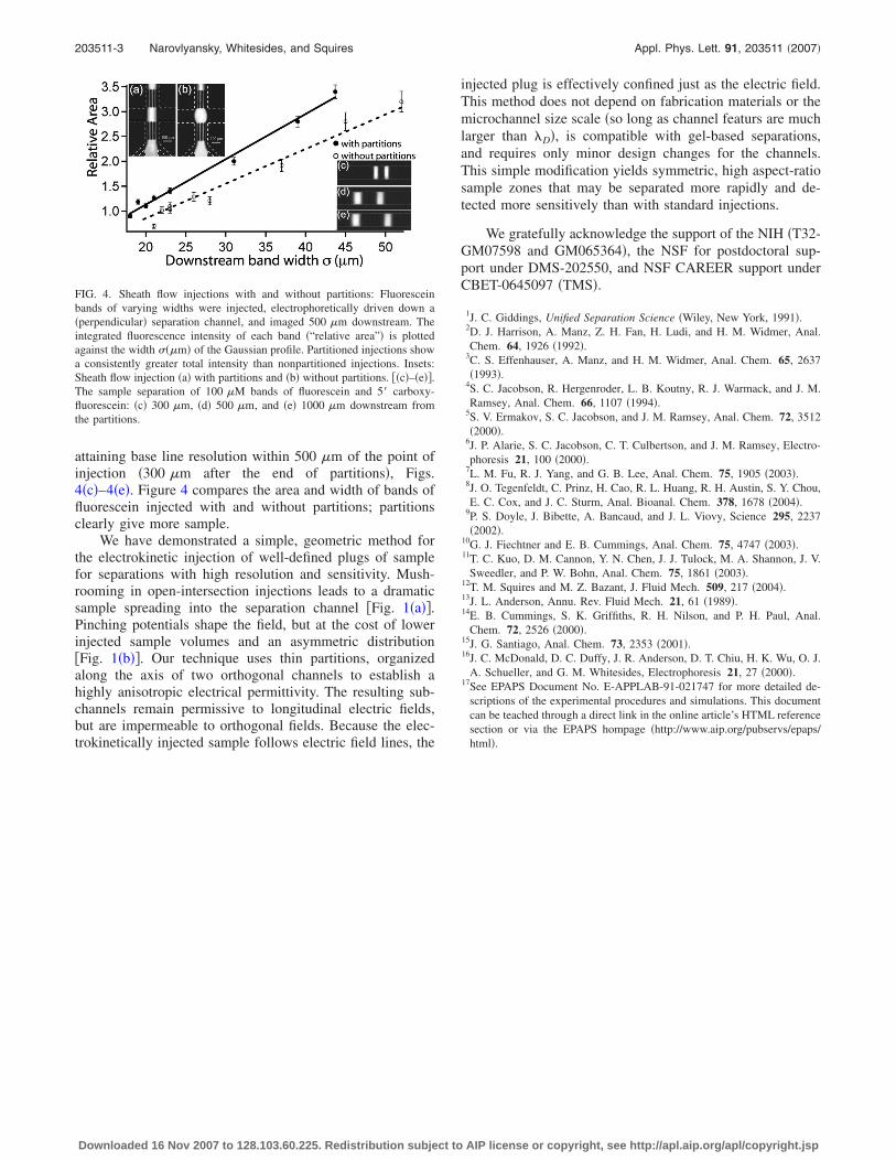
attaining base line resolution within 500 �m of the point ofinjection �300 �m after the end of partitions�, Figs.4�c�–4�e�. Figure 4 compares the area and width of bands offluorescein injected with and without partitions; partitionsclearly give more sample.
We have demonstrated a simple, geometric method forthe electrokinetic injection of well-defined plugs of samplefor separations with high resolution and sensitivity. Mush-rooming in open-intersection injections leads to a dramaticsample spreading into the separation channel �Fig. 1�a��.Pinching potentials shape the field, but at the cost of lowerinjected sample volumes and an asymmetric distribution�Fig. 1�b��. Our technique uses thin partitions, organizedalong the axis of two orthogonal channels to establish ahighly anisotropic electrical permittivity. The resulting sub-channels remain permissive to longitudinal electric fields,but are impermeable to orthogonal fields. Because the elec-trokinetically injected sample follows electric field lines, the
injected plug is effectively confined just as the electric field.This method does not depend on fabrication materials or themicrochannel size scale �so long as channel featurs are muchlarger than �D�, is compatible with gel-based separations,and requires only minor design changes for the channels.This simple modification yields symmetric, high aspect-ratiosample zones that may be separated more rapidly and de-tected more sensitively than with standard injections.
We gratefully acknowledge the support of the NIH �T32-GM07598 and GM065364�, the NSF for postdoctoral sup-port under DMS-202550, and NSF CAREER support underCBET-0645097 �TMS�.
1J. C. Giddings, Unified Separation Science �Wiley, New York, 1991�.2D. J. Harrison, A. Manz, Z. H. Fan, H. Ludi, and H. M. Widmer, Anal.Chem. 64, 1926 �1992�.
3C. S. Effenhauser, A. Manz, and H. M. Widmer, Anal. Chem. 65, 2637�1993�.
4S. C. Jacobson, R. Hergenroder, L. B. Koutny, R. J. Warmack, and J. M.Ramsey, Anal. Chem. 66, 1107 �1994�.
5S. V. Ermakov, S. C. Jacobson, and J. M. Ramsey, Anal. Chem. 72, 3512�2000�.
6J. P. Alarie, S. C. Jacobson, C. T. Culbertson, and J. M. Ramsey, Electro-phoresis 21, 100 �2000�.
7L. M. Fu, R. J. Yang, and G. B. Lee, Anal. Chem. 75, 1905 �2003�.8J. O. Tegenfeldt, C. Prinz, H. Cao, R. L. Huang, R. H. Austin, S. Y. Chou,E. C. Cox, and J. C. Sturm, Anal. Bioanal. Chem. 378, 1678 �2004�.
9P. S. Doyle, J. Bibette, A. Bancaud, and J. L. Viovy, Science 295, 2237�2002�.
10G. J. Fiechtner and E. B. Cummings, Anal. Chem. 75, 4747 �2003�.11T. C. Kuo, D. M. Cannon, Y. N. Chen, J. J. Tulock, M. A. Shannon, J. V.
Sweedler, and P. W. Bohn, Anal. Chem. 75, 1861 �2003�.12T. M. Squires and M. Z. Bazant, J. Fluid Mech. 509, 217 �2004�.13J. L. Anderson, Annu. Rev. Fluid Mech. 21, 61 �1989�.14E. B. Cummings, S. K. Griffiths, R. H. Nilson, and P. H. Paul, Anal.
Chem. 72, 2526 �2000�.15J. G. Santiago, Anal. Chem. 73, 2353 �2001�.16J. C. McDonald, D. C. Duffy, J. R. Anderson, D. T. Chiu, H. K. Wu, O. J.
A. Schueller, and G. M. Whitesides, Electrophoresis 21, 27 �2000�.17See EPAPS Document No. E-APPLAB-91-021747 for more detailed de-
scriptions of the experimental procedures and simulations. This documentcan be teached through a direct link in the online article’s HTML referencesection or via the EPAPS hompage �http://www.aip.org/pubservs/epaps/html�.
FIG. 4. Sheath flow injections with and without partitions: Fluoresceinbands of varying widths were injected, electrophoretically driven down a�perpendicular� separation channel, and imaged 500 �m downstream. Theintegrated fluorescence intensity of each band �“relative area”� is plottedagainst the width ���m� of the Gaussian profile. Partitioned injections showa consistently greater total intensity than nonpartitioned injections. Insets:Sheath flow injection �a� with partitions and �b� without partitions. ��c�–�e��.The sample separation of 100 �M bands of fluorescein and 5� carboxy-fluorescein: �c� 300 �m, �d� 500 �m, and �e� 1000 �m downstream fromthe partitions.
203511-3 Narovlyansky, Whitesides, and Squires Appl. Phys. Lett. 91, 203511 �2007�
Downloaded 16 Nov 2007 to 128.103.60.225. Redistribution subject to AIP license or copyright, see http://apl.aip.org/apl/copyright.jsp


