Yagi
Antenna
Tutorial
Copyright K7JLT 1
Yagi: The Man & Developments
• In the 1920’s two Japanese electrical engineers, Hidetsugu
Yagi and Shintaro Uda at Tohoku University in Sendai Japan,
investigated ways to improve transmitted short wave signals.
• The investigation started with what we now call a dipole
antenna.
• As the investigation continued it was found that additional wire
elements could improve the strength of the transmitted signal.
• The resulting antenna received a Japanese patent in 1926 and
a U.S. patented in 1932.
• This antenna is now known as a Yagi. One of the few
electronic devises that is known by the inventors name.
• Hidetsugu Yagi authored many papers and received patents in
microwave power generation before his death in 1976. Copyright K7JLT 2
Yagi Antennas
What’s a Yagi Antenna?
• As we have learned a Yagi starts with a dipole.
• A Yagi antenna then adds additional elements that
uses parasitic coupling to the dipole to increase
antenna gain.
• A Yagi antenna has at least 1 driven and 1 or more
un-driven elements.
• All Yagi elements are parallel to one another.
Copyright K7JLT 3
Yagi Antennas
What’s parasitic coupling?
• Parasitic coupling is where a antenna element
receives energy from a driven element (dipole) and
re-radiates this energy.
• The act of receiving of energy from the driven element
is known is also known as mutual coupling where a
two-way influence occurs between elements.
• The element diameter, length and distance between
elements effects the amount coupling and radiation.
• Elements longer than the driven element are called
reflectors and shorter elements are called directors.
Copyright K7JLT 4
Yagi Designs
There are thousands of Yagi Designs, so for
consistency in this presentation, the ARRL Antenna
Handbook 21st Edition Medium Duty Yagi’s designed
by N6BV have been chosen.
These Yagi were optimized for Gain, Front-to-Rear
Ratio and Bandwidth allowing consistency between
antennas for comparison.
Copyright K7JLT 5
First let’s look at the relation
between the Yagi Antenna and
the ground, where the antenna
is mounted on a tower of
variable height.
Copyright K7JLT 6
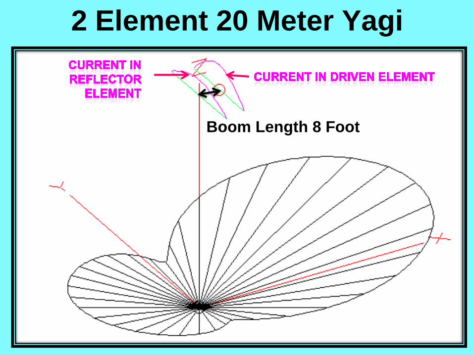
2 Element 20 Meter Yagi
Copyright K7JLT 7
Boom Length 8 Foot
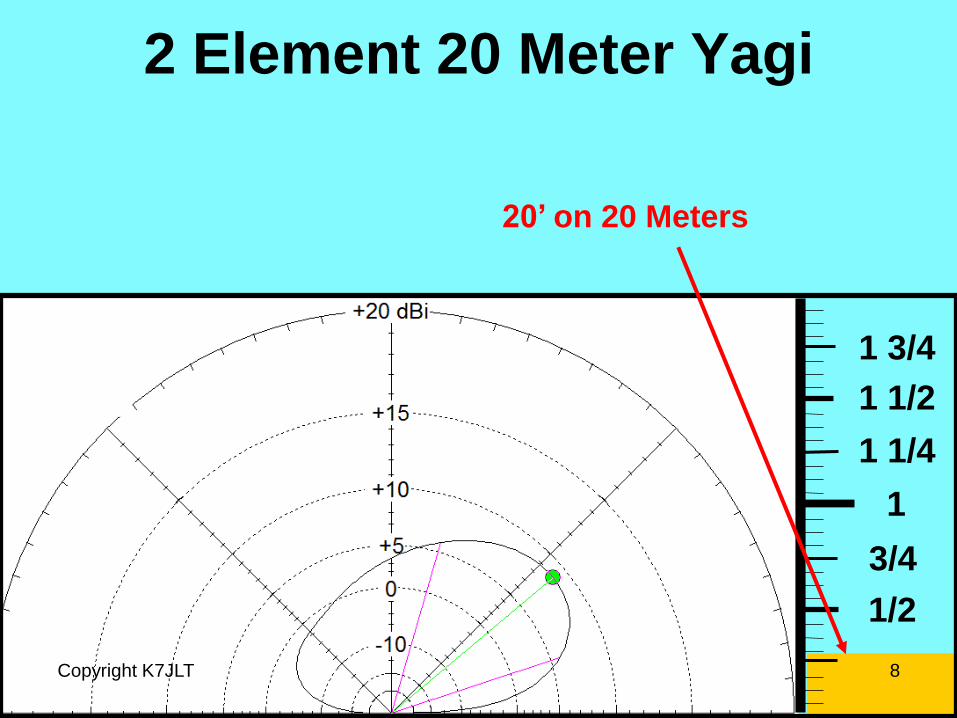
2 Element 20 Meter Yagi
1/2
3/4
1
1 1/4
1 1/2
1 3/4
Copyright K7JLT 8
20’ on 20 Meters
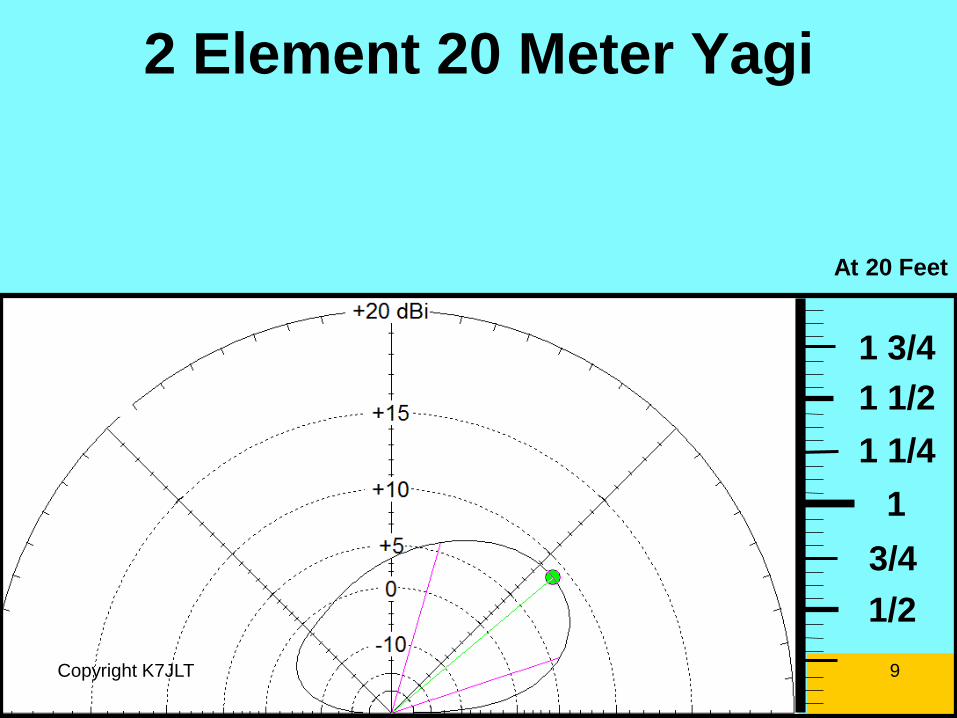
2 Element 20 Meter Yagi
1/2
3/4
1
1 1/4
1 1/2
1 3/4
At 20 Feet
Copyright K7JLT 9
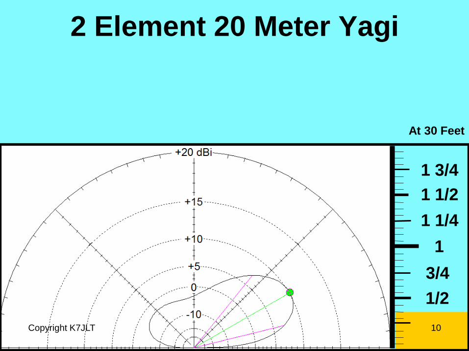
2 Element 20 Meter Yagi
1/2
3/4
1
1 1/4
1 1/2
1 3/4
At 30 Feet
Copyright K7JLT 10
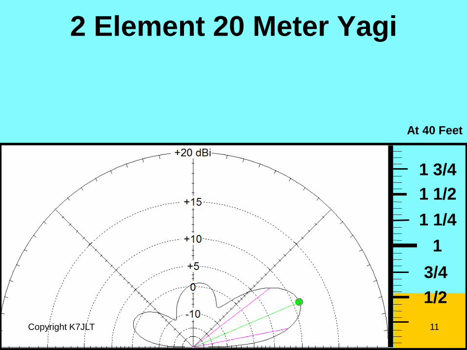
2 Element 20 Meter Yagi
1/2
3/4
1
1 1/4
1 1/2
1 3/4
At 40 Feet
Copyright K7JLT 11

2 Element 20 Meter Yagi
1/2
3/4
1
1 1/4
1 1/2
1 3/4
At 50 Feet
Copyright K7JLT 12
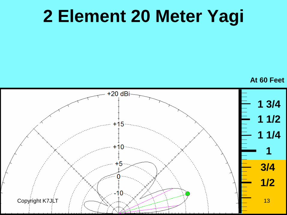
2 Element 20 Meter Yagi
1/2
3/4
1
1 1/4
1 1/2
1 3/4
At 60 Feet
Copyright K7JLT 13
2 Element 20 Meter Yagi
1/2
3/4
1
1 1/4
1 1/2
1 3/4
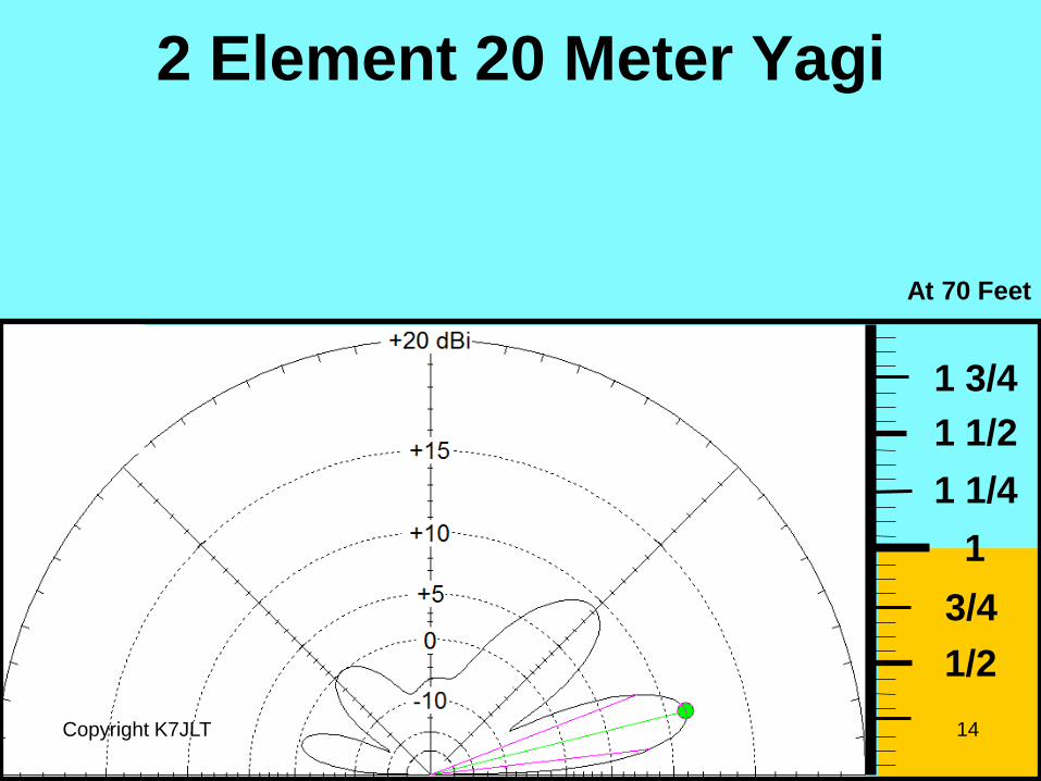
At 70 Feet
Copyright K7JLT 14
2 Element 20 Meter Yagi
1/2
3/4
1
1 1/4
1 1/2
1 3/4
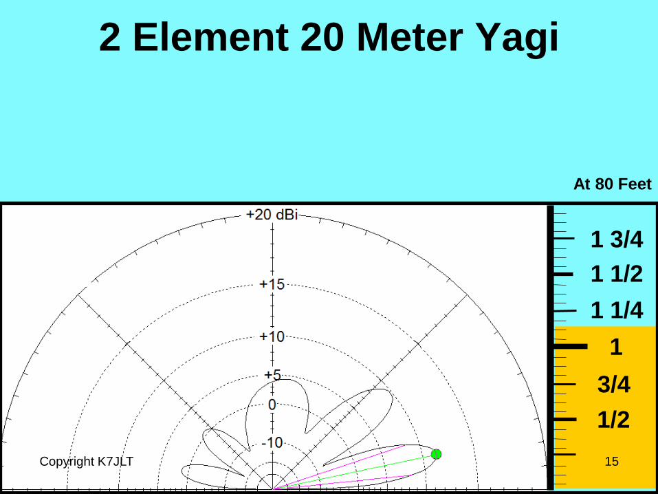
At 80 Feet
Copyright K7JLT 15

2 Element 20 Meter Yagi
Copyright K7JLT 16
1/2
3/4
1
1 1/4
1 1/2
1 3/4
At 90 Feet
2 Element 20 Meter Yagi
Copyright K7JLT 17
1/2
3/4
1
1 1/4
1 1/2
1 3/4
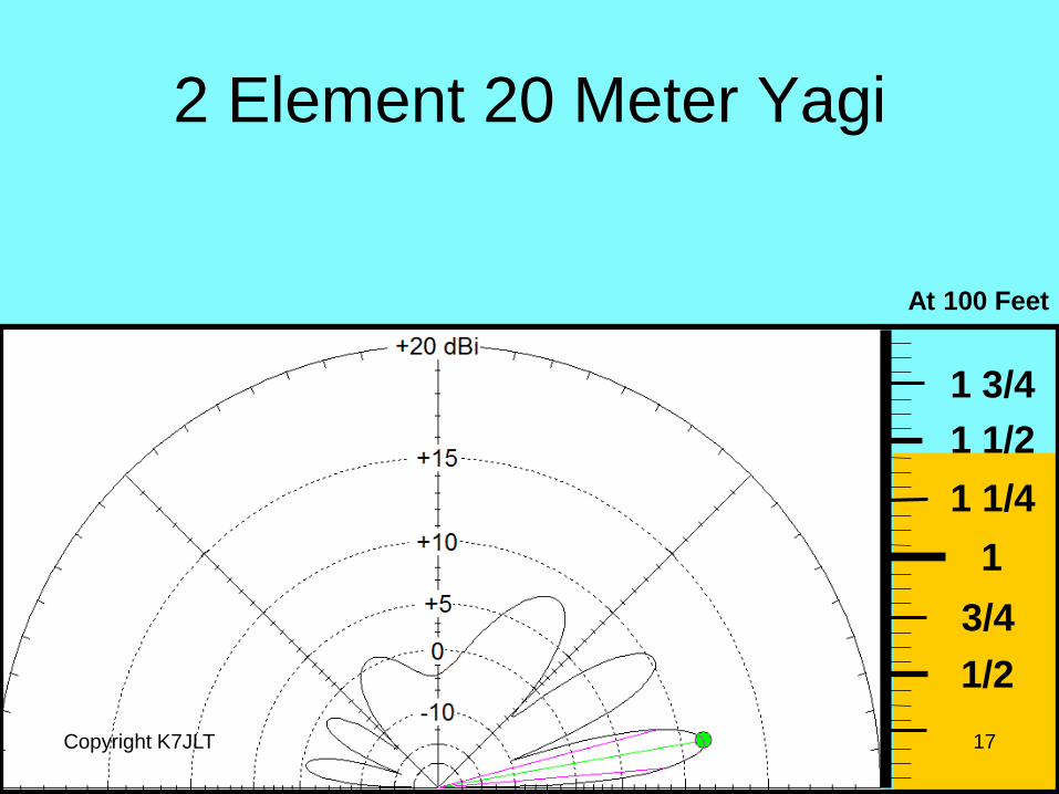
At 100 Feet
2 Element 20 Meter Yagi
Copyright K7JLT 18
1/2
3/4
1
1 1/4
1 1/2
1 3/4
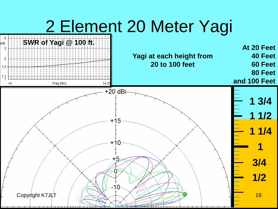
At 20 Feet
40 Feet
60 Feet
80 Feet
and 100 Feet
SWR of Yagi @ 100 ft.
Yagi at each height from
20 to 100 feet
2 Element 20 Meter Yagi
Copyright K7JLT 19
1/2
3/4
1
1 1/4
1 1/2
1 3/4
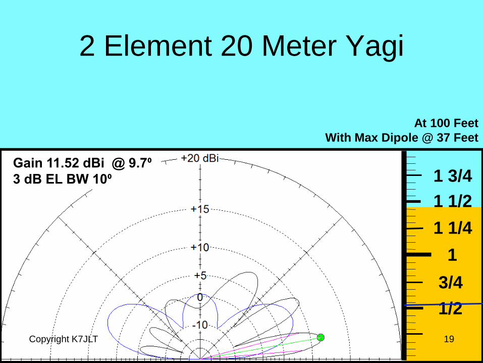
At 100 Feet
With Max Dipole @ 37 Feet
Gain 11.52 dBi @ 9.7⁰
3 dB EL BW 10⁰
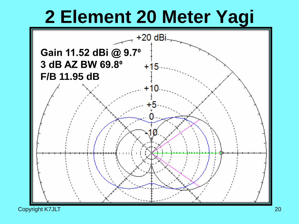
2 Element 20 Meter Yagi
Gain 11.52 dBi @ 9.7⁰
3 dB AZ BW 69.8⁰
F/B 11.95 dB
Copyright K7JLT 20
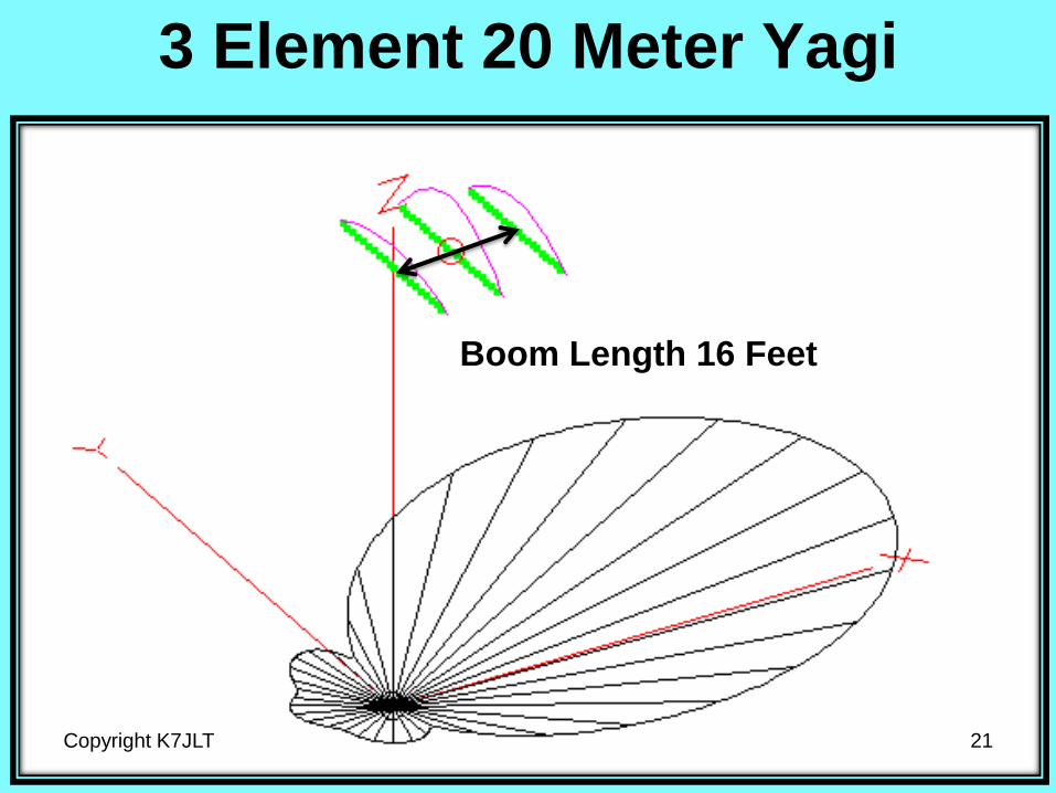
3 Element 20 Meter Yagi
Copyright K7JLT 21
Boom Length 16 Feet
3 Element 20 Meter Yagi
Copyright K7JLT 22
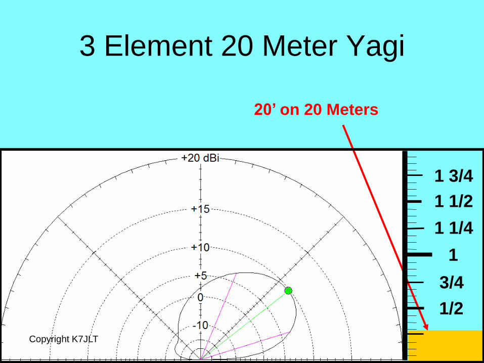
20’ on 20 Meters
1/2
3/4
1
1 1/4
1 1/2
1 3/4

3 Element 20 Meter Yagi
Copyright K7JLT 23
1/2
3/4
1
1 1/4
1 1/2
1 3/4
At 20 Feet
3 Element 20 Meter Yagi
Copyright K7JLT 24
1/2
3/4
1
1 1/4
1 1/2
1 3/4
At 30 Feet

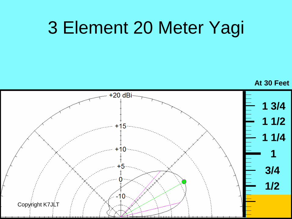
3 Element 20 Meter Yagi
Copyright K7JLT 25
1/2
3/4
1
1 1/4
1 1/2
1 3/4
At 40 Feet

3 Element 20 Meter Yagi
Copyright K7JLT 26
1/2
3/4
1
1 1/4
1 1/2
1 3/4
At 50 Feet

3 Element 20 Meter Yagi
Copyright K7JLT 27
1/2
3/4
1
1 1/4
1 1/2
1 3/4
At 60 Feet
3 Element 20 Meter Yagi
Copyright K7JLT 28
1/2
3/4
1
1 1/4
1 1/2
1 3/4
At 70 Feet
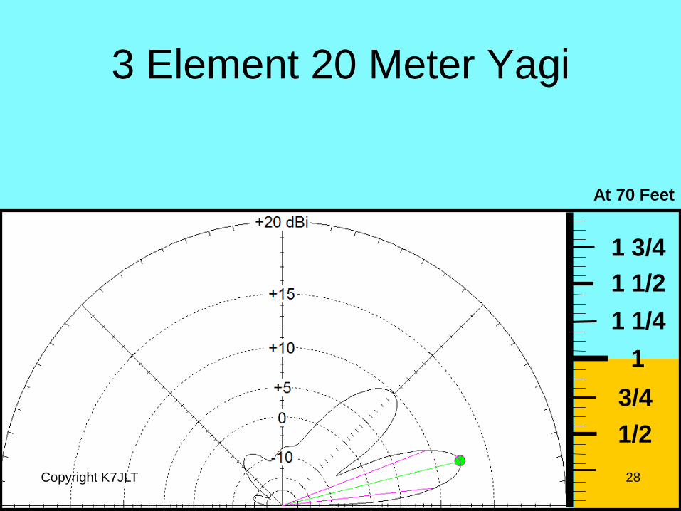
3 Element 20 Meter Yagi
Copyright K7JLT 29
1/2
3/4
1
1 1/4
1 1/2
1 3/4
At 80 Feet

3 Element 20 Meter Yagi
Copyright K7JLT 30
1/2
3/4
1
1 1/4
1 1/2
1 3/4
At 90 Feet
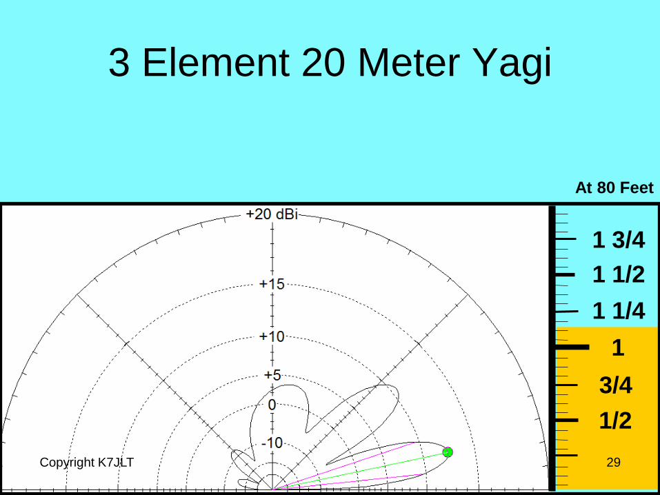
3 Element 20 Meter Yagi
Copyright K7JLT 31
1/2
3/4
1
1 1/4
1 1/2
1 3/4
At 100 Feet
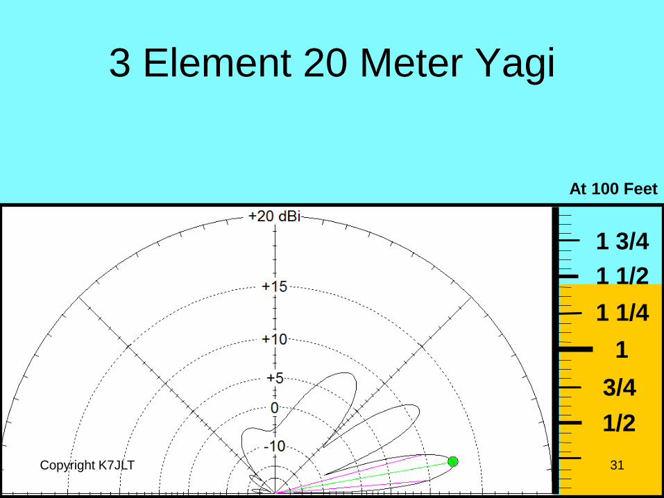
3 Element 20 Meter Yagi
Copyright K7JLT 32
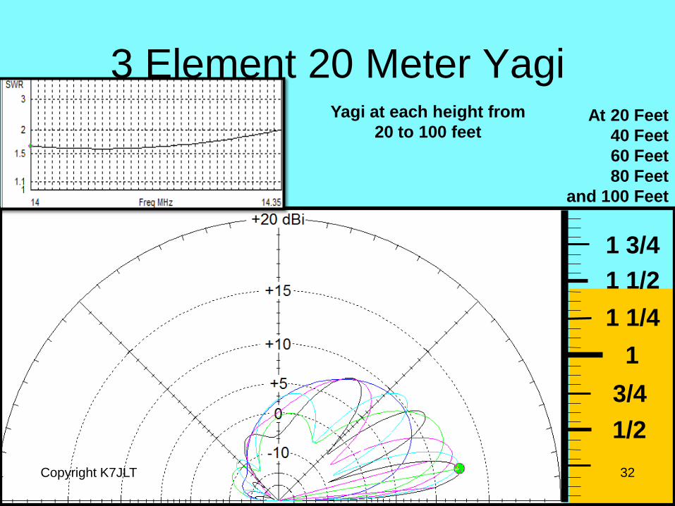
1/2
3/4
1
1 1/4
1 1/2
1 3/4
At 20 Feet
40 Feet
60 Feet
80 Feet
and 100 Feet
Yagi at each height from
20 to 100 feet
3 Element 20 Meter Yagi
Copyright K7JLT 33
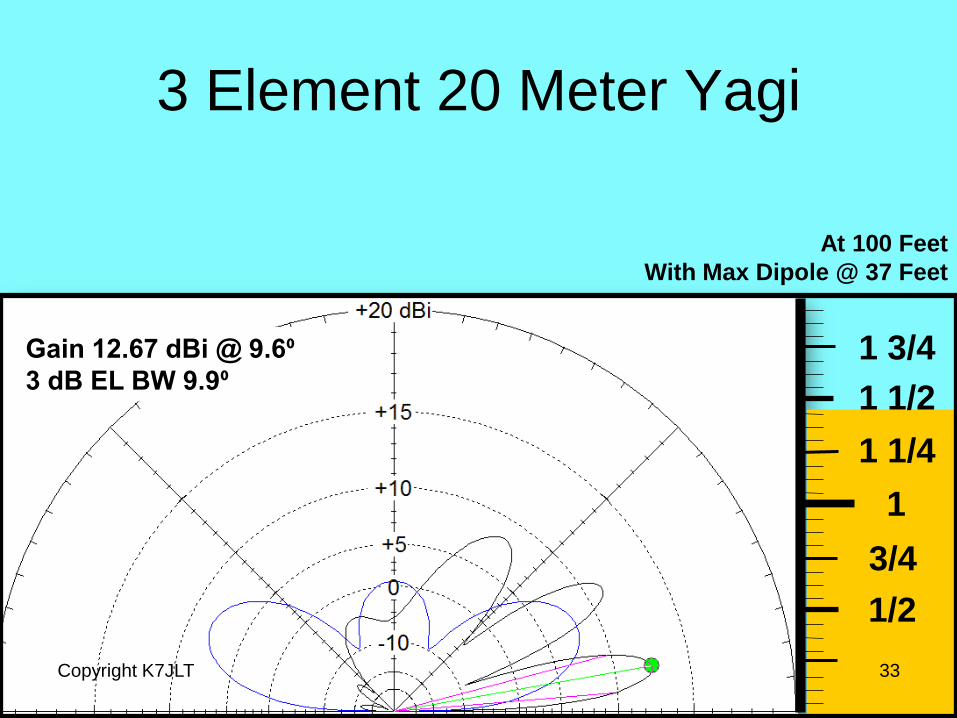
1/2
3/4
1
1 1/4
1 1/2
1 3/4
At 100 Feet
With Max Dipole @ 37 Feet
Gain 12.67 dBi @ 9.6⁰
3 dB EL BW 9.9⁰
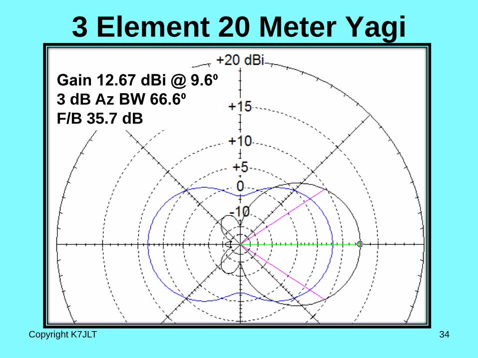
3 Element 20 Meter Yagi
Gain 12.67 dBi @ 9.6⁰
3 dB Az BW 66.6⁰
F/B 35.7 dB
Copyright K7JLT 34
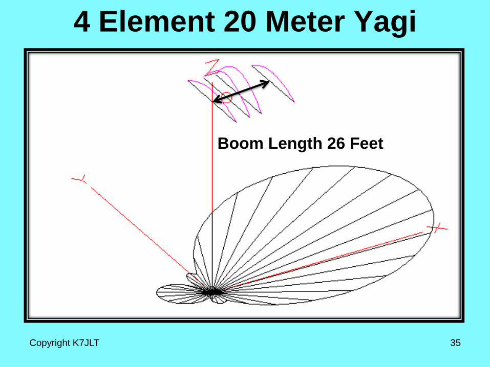
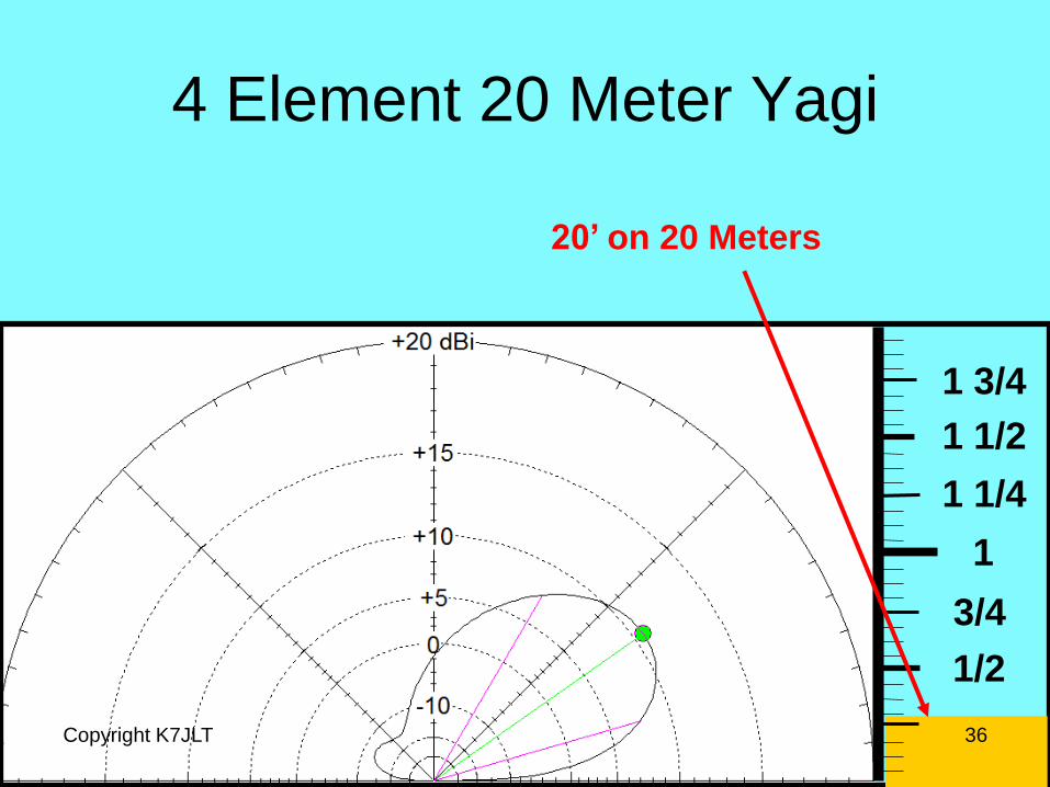
4 Element 20 Meter Yagi
Copyright K7JLT 35
Boom Length 26 Feet
1/2
3/4
1
1 1/4
1 1/2
1 3/4
4 Element 20 Meter Yagi
36
20’ on 20 Meters
Copyright K7JLT
1/2
3/4
1
1 1/4
1 1/2
1 3/4
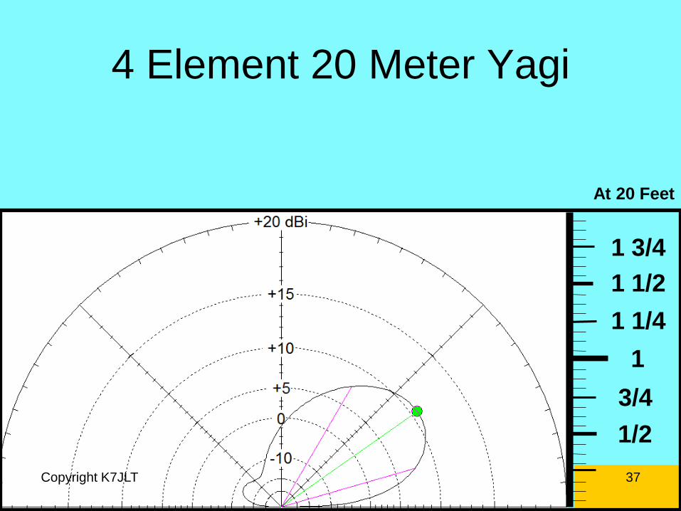
4 Element 20 Meter Yagi
Copyright K7JLT 37
At 20 Feet

1/2
3/4
1
1 1/4
1 1/2
1 3/4
4 Element 20 Meter Yagi
Copyright K7JLT 38
At 30 Feet
1/2
3/4
1
1 1/4
1 1/2
1 3/4
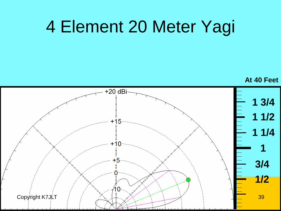
4 Element 20 Meter Yagi
Copyright K7JLT 39
At 40 Feet

1/2
3/4
1
1 1/4
1 1/2
1 3/4
4 Element 20 Meter Yagi
Copyright K7JLT 40
At 50 Feet
1/2
3/4
1
1 1/4
1 1/2
1 3/4
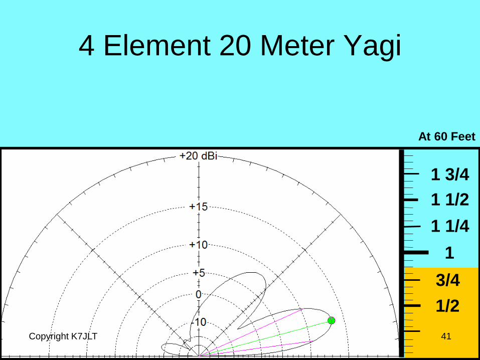
4 Element 20 Meter Yagi
Copyright K7JLT 41
At 60 Feet
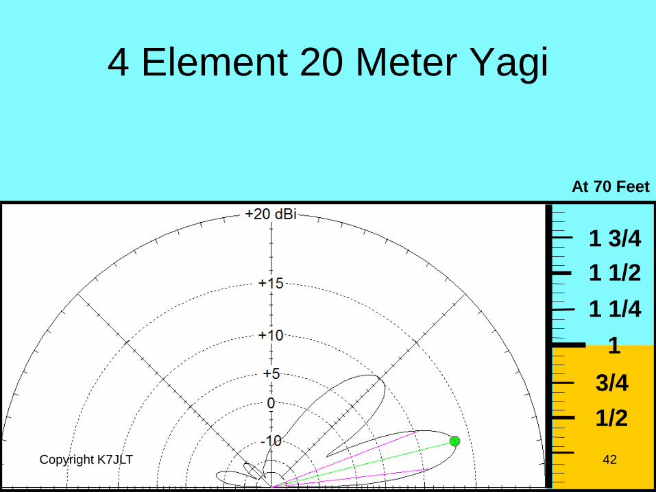
4 Element 20 Meter Yagi
Copyright K7JLT 42
1/2
3/4
1
1 1/4
1 1/2
1 3/4
At 70 Feet
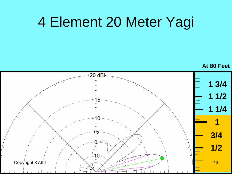
4 Element 20 Meter Yagi
Copyright K7JLT 43
1/2
3/4
1
1 1/4
1 1/2
1 3/4
At 80 Feet

4 Element 20 Meter Yagi
Copyright K7JLT 44
1/2
3/4
1
1 1/4
1 1/2
1 3/4
At 90 Feet
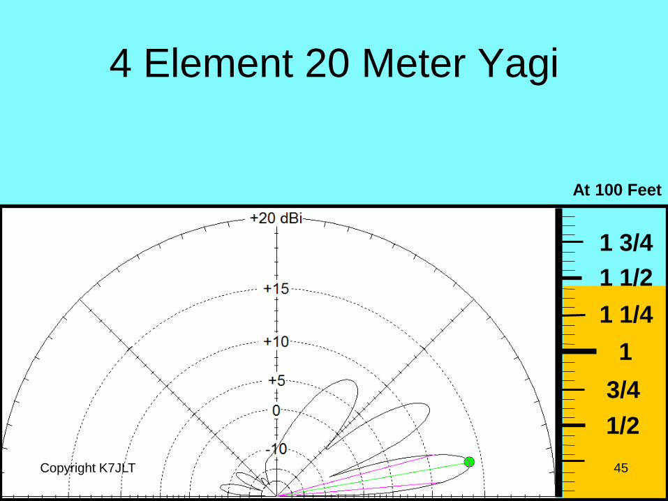
4 Element 20 Meter Yagi
Copyright K7JLT 45
1/2
3/4
1
1 1/4
1 1/2
1 3/4
At 100 Feet

4 Element 20 Meter Yagi
Copyright K7JLT 46
1/2
3/4
1
1 1/4
1 1/2
1 3/4
At 20 Feet
40 Feet
60 Feet
80 Feet
and 100 Feet
Yagi at each height from
20 to 100 feet
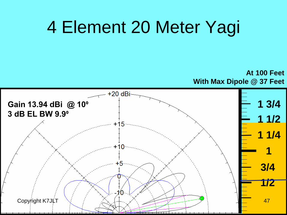
4 Element 20 Meter Yagi
Copyright K7JLT 47
1/2
3/4
1
1 1/4
1 1/2
1 3/4
At 100 Feet
With Max Dipole @ 37 Feet
Gain 13.94 dBi @ 10⁰
3 dB EL BW 9.9⁰
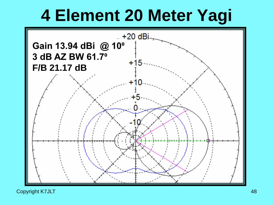
4 Element 20 Meter Yagi
Gain 13.94 dBi @ 10⁰
3 dB AZ BW 61.7⁰
F/B 21.17 dB
Copyright K7JLT 48
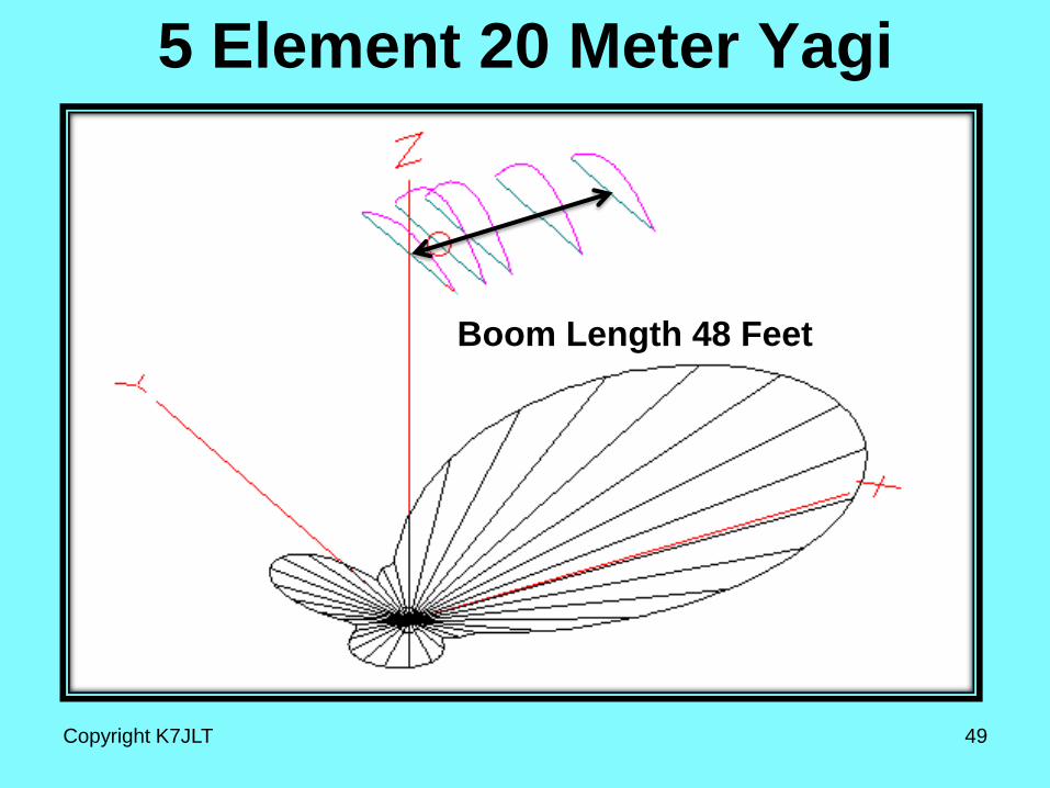
5 Element 20 Meter Yagi
Copyright K7JLT 49
Boom Length 48 Feet
1/2
3/4
1
1 1/4
1 1/2
1 3/4
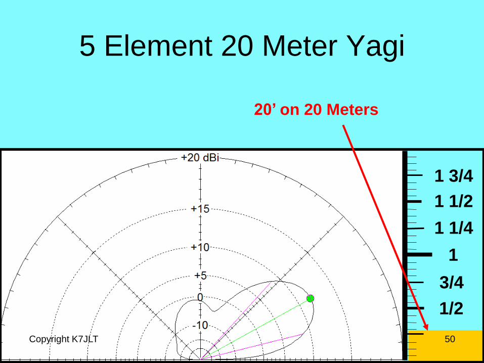
5 Element 20 Meter Yagi
Copyright K7JLT 50
20’ on 20 Meters
1/2
3/4
1
1 1/4
1 1/2
1 3/4
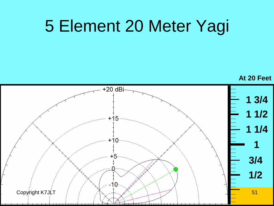
5 Element 20 Meter Yagi
Copyright K7JLT 51
At 20 Feet

1/2
3/4
1
1 1/4
1 1/2
1 3/4
5 Element 20 Meter Yagi
Copyright K7JLT 52
At 30 Feet

1/2
3/4
1
1 1/4
1 1/2
1 3/4
5 Element 20 Meter Yagi
Copyright K7JLT 53
At 40 Feet
1/2
3/4
1
1 1/4
1 1/2
1 3/4
5 Element 20 Meter Yagi
Copyright K7JLT 54
At 50 Feet

1/2
3/4
1
1 1/4
1 1/2
1 3/4
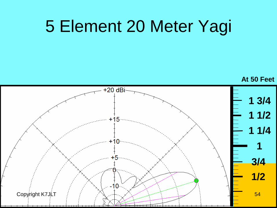
5 Element 20 Meter Yagi
Copyright K7JLT 55
At 60 Feet

1/2
3/4
1
1 1/4
1 1/2
1 3/4
5 Element 20 Meter Yagi
Copyright K7JLT 56
At 70 Feet
5 Element 20 Meter Yagi
Copyright K7JLT 57
1/2
3/4
1
1 1/4
1 1/2
1 3/4
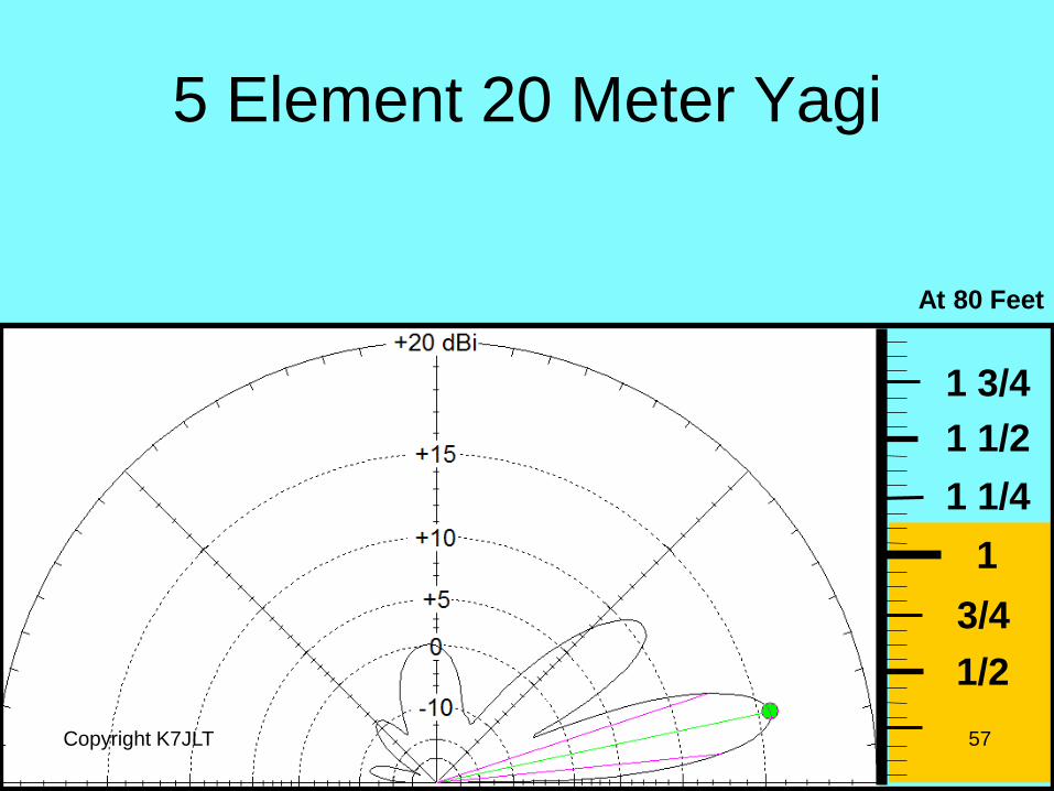
At 80 Feet
5 Element 20 Meter Yagi
Copyright K7JLT 58
1/2
3/4
1
1 1/4
1 1/2
1 3/4
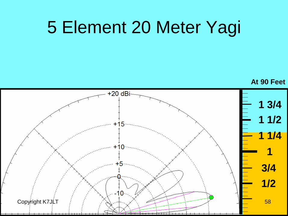
At 90 Feet

5 Element 20 Meter Yagi
Copyright K7JLT 59
1/2
3/4
1
1 1/4
1 1/2
1 3/4
At 100 Feet

5 Element 20 Meter Yagi
Copyright K7JLT 60
1/2
3/4
1
1 1/4
1 1/2
1 3/4
At 20 Feet
40 Feet
60 Feet
80 Feet
and 100 Feet
Yagi at each height from
20 to 100 feet
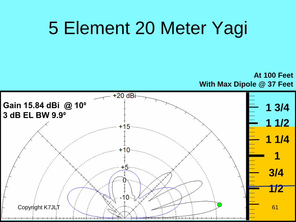
5 Element 20 Meter Yagi
Copyright K7JLT 61
1/2
3/4
1
1 1/4
1 1/2
1 3/4
At 100 Feet
With Max Dipole @ 37 Feet
Gain 15.84 dBi @ 10⁰
3 dB EL BW 9.9⁰
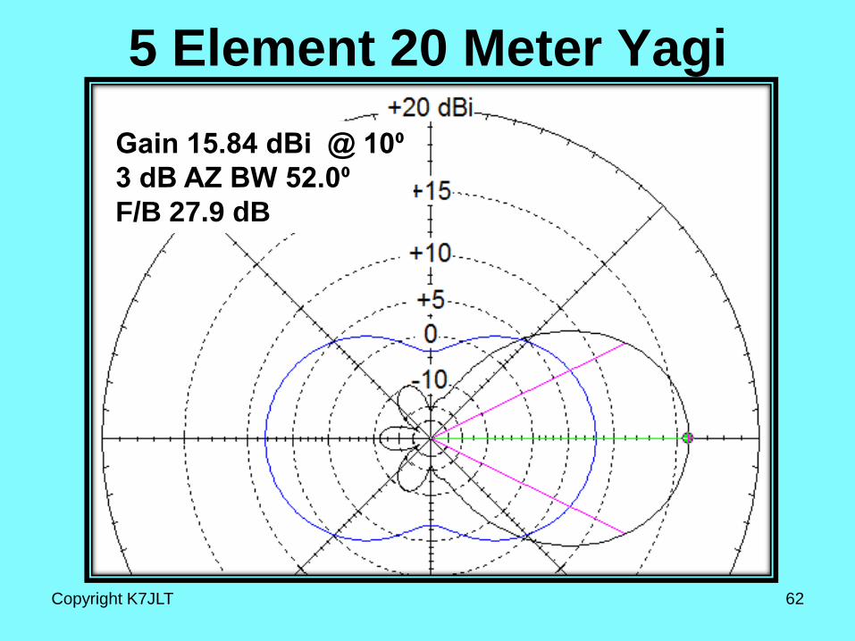
5 Element 20 Meter Yagi
Gain 15.84 dBi @ 10⁰
3 dB AZ BW 52.0⁰
F/B 27.9 dB
Copyright K7JLT 62
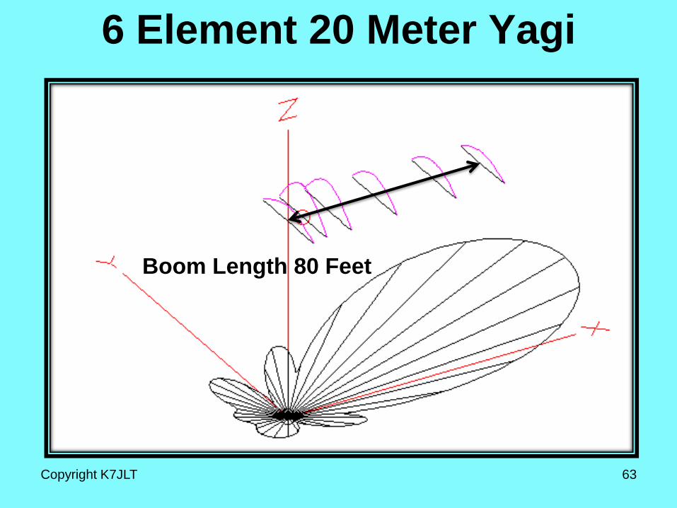
6 Element 20 Meter Yagi
Copyright K7JLT 63
Boom Length 80 Feet

1/2
3/4
1
1 1/4
1 1/2
1 3/4
6 Element 20 Meter Yagi
Copyright K7JLT 64
20’ on 20 Meters

6 Element 20 Meter Yagi
Copyright K7JLT 65
1/2
3/4
1
1 1/4
1 1/2
1 3/4
At 20 Feet
1/2
3/4
1
1 1/4
1 1/2
1 3/4
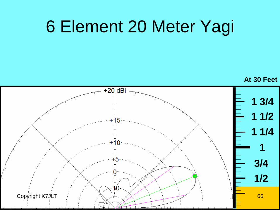
6 Element 20 Meter Yagi
Copyright K7JLT 66
At 30 Feet
1/2
3/4
1
1 1/4
1 1/2
1 3/4
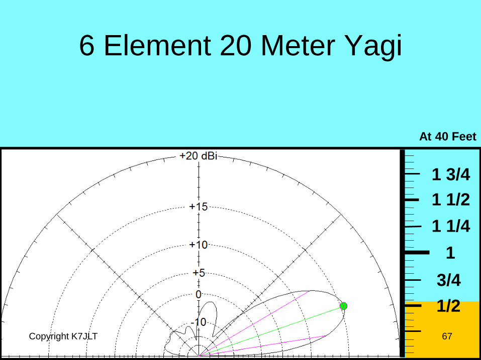
6 Element 20 Meter Yagi
Copyright K7JLT 67
At 40 Feet
1/2
3/4
1
1 1/4
1 1/2
1 3/4
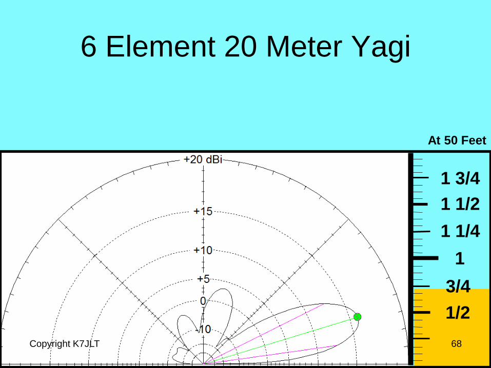
6 Element 20 Meter Yagi
Copyright K7JLT 68
At 50 Feet
1/2
3/4
1
1 1/4
1 1/2
1 3/4
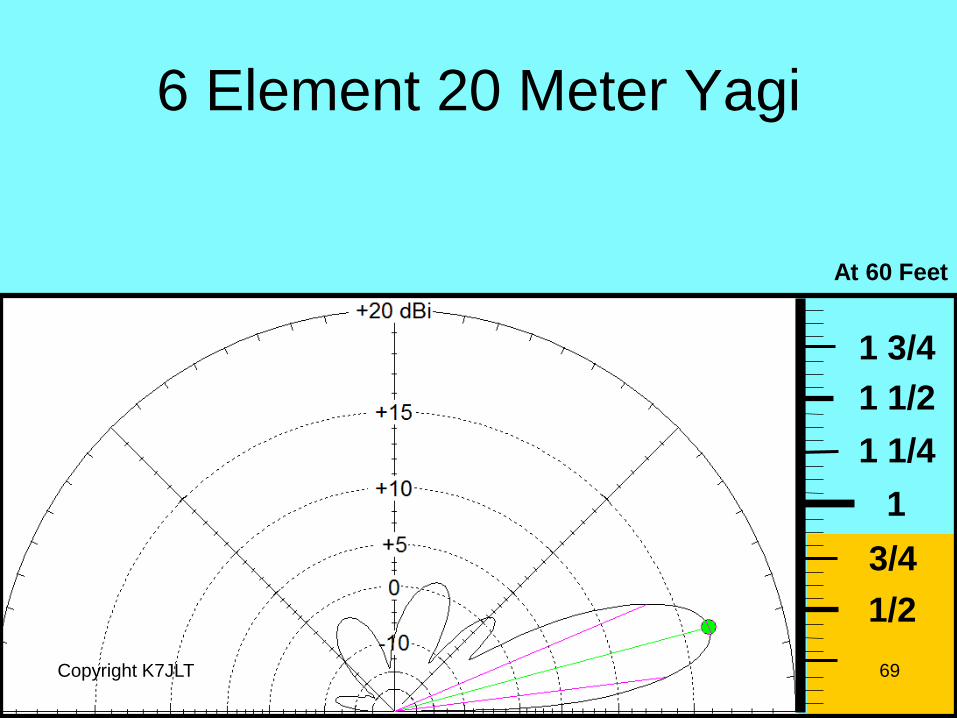
6 Element 20 Meter Yagi
Copyright K7JLT 69
At 60 Feet

6 Element 20 Meter Yagi
Copyright K7JLT 70
1/2
3/4
1
1 1/4
1 1/2
1 3/4
At 70 Feet
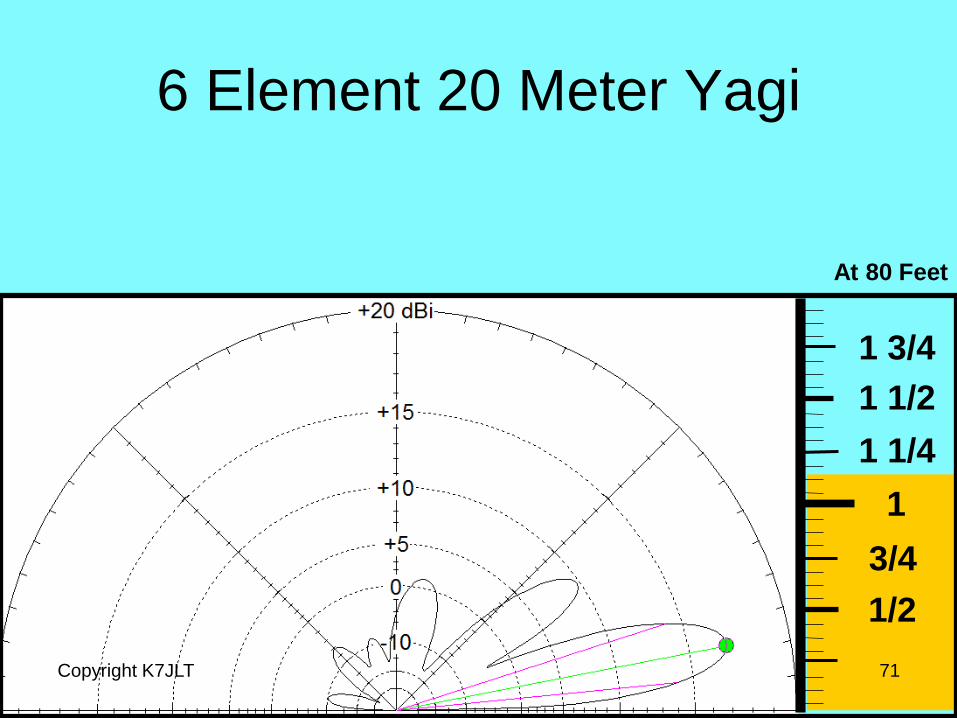
6 Element 20 Meter Yagi
Copyright K7JLT 71
1/2
3/4
1
1 1/4
1 1/2
1 3/4
At 80 Feet
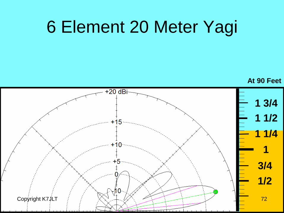
6 Element 20 Meter Yagi
Copyright K7JLT 72
1/2
3/4
1
1 1/4
1 1/2
1 3/4
At 90 Feet
6 Element 20 Meter Yagi
Copyright K7JLT 73
1/2
3/4
1
1 1/4
1 1/2
1 3/4
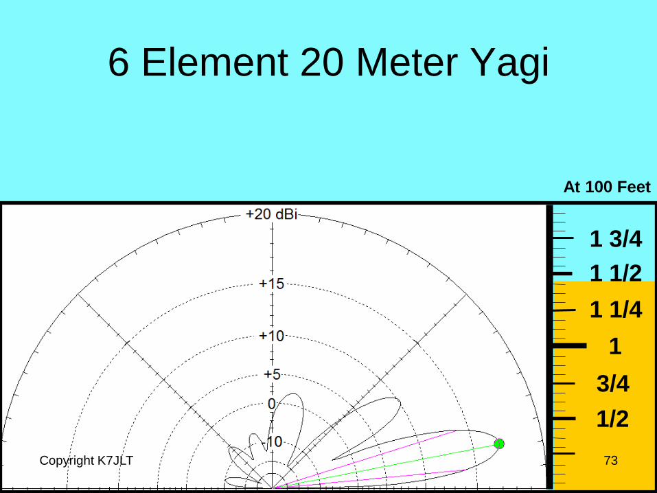
At 100 Feet
6 Element 20 Meter Yagi
Copyright K7JLT 74
1/2
3/4
1
1 1/4
1 1/2
1 3/4
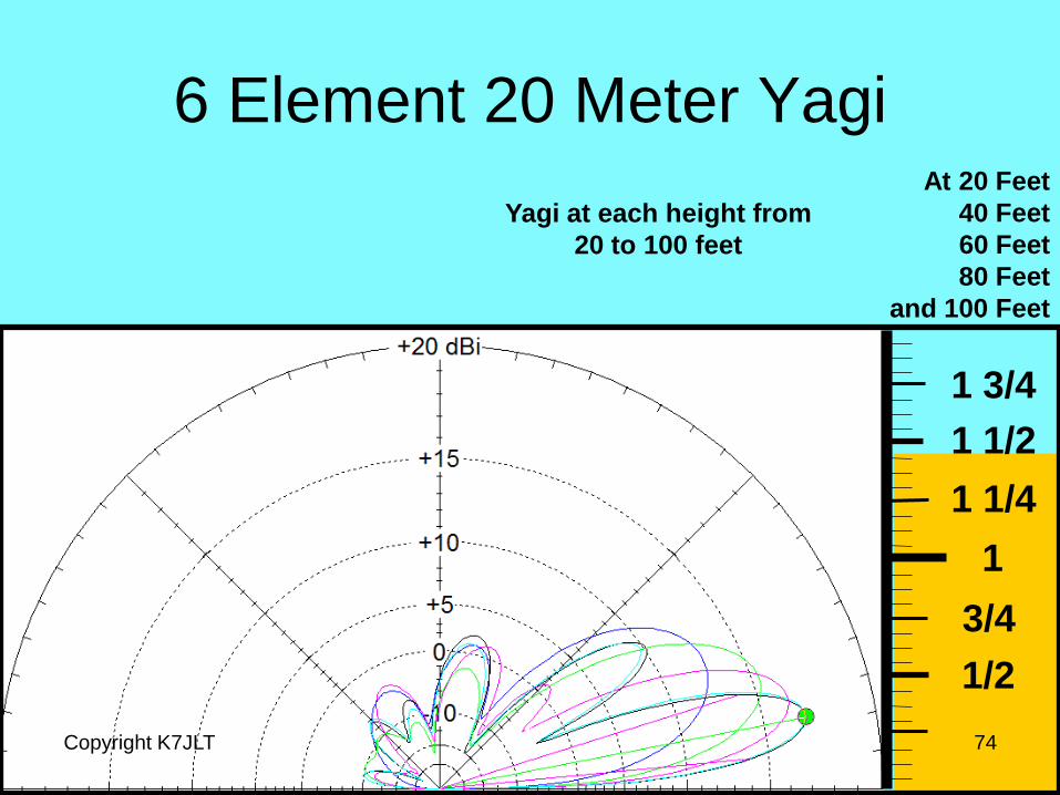
At 20 Feet
40 Feet
60 Feet
80 Feet
and 100 Feet
Yagi at each height from
20 to 100 feet
6 Element 20 Meter Yagi
Copyright K7JLT 75
1/2
3/4
1
1 1/4
1 1/2
1 3/4
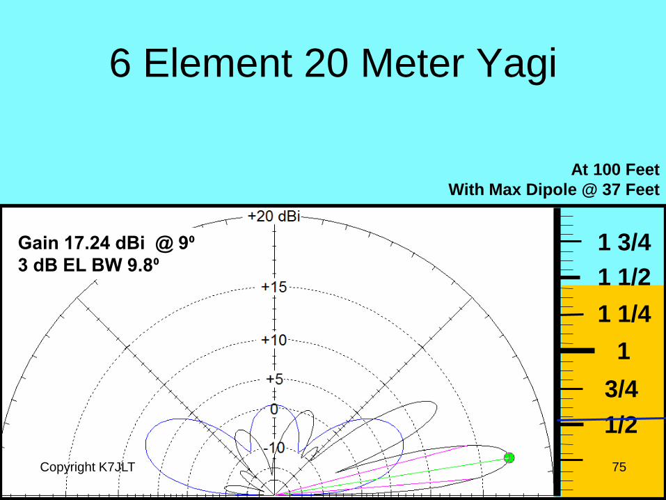
At 100 Feet
With Max Dipole @ 37 Feet
Gain 17.24 dBi @ 9⁰
3 dB EL BW 9.8⁰
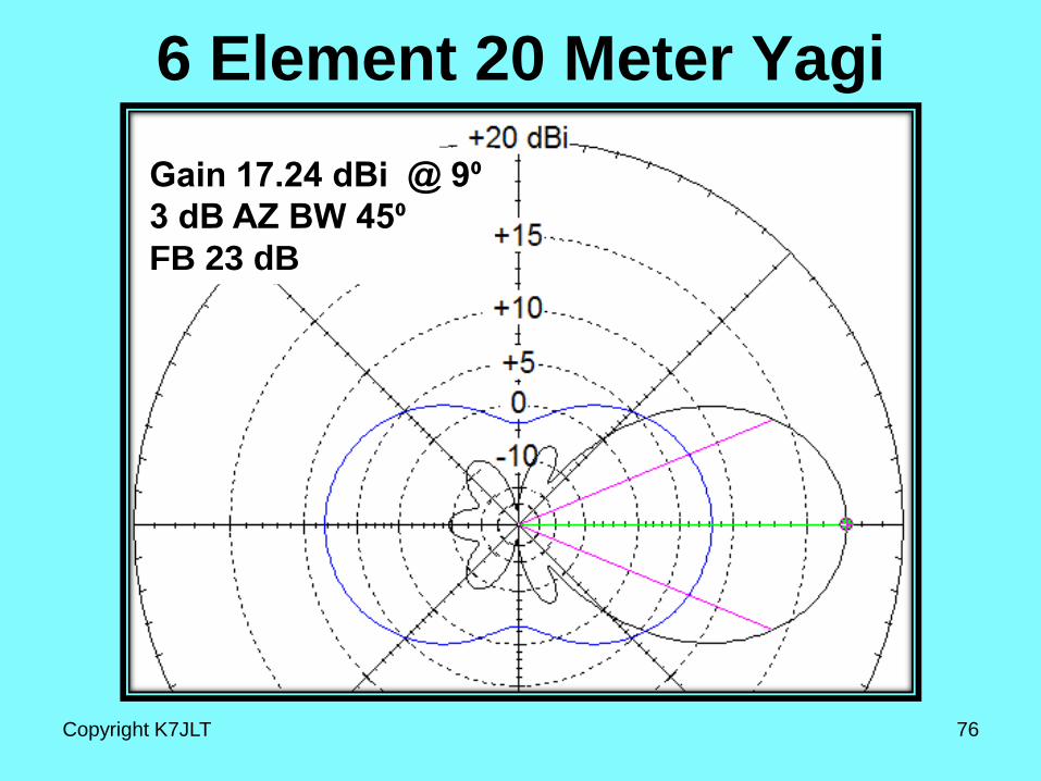
6 Element 20 Meter Yagi
Gain 17.24 dBi @ 9⁰
3 dB AZ BW 45⁰
FB 23 dB
Copyright K7JLT 76
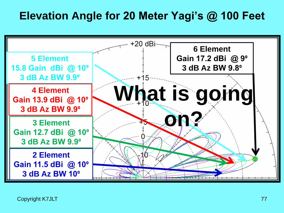
Elevation Angle for 20 Meter Yagi’s @ 100 Feet
6 Element
Gain 17.2 dBi @ 9⁰
3 dB Az BW 9.8⁰
Copyright K7JLT 77
5 Element
15.8 Gain dBi @ 10⁰
3 dB Az BW 9.9⁰
4 Element
Gain 13.9 dBi @ 10⁰
3 dB Az BW 9.9⁰
3 Element
Gain 12.7 dBi @ 10⁰
3 dB Az BW 9.9⁰
2 Element
Gain 11.5 dBi @ 10⁰
3 dB Az BW 10⁰
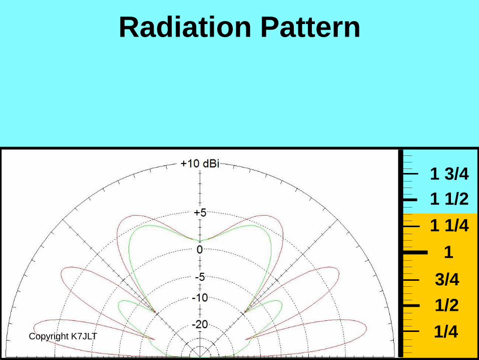
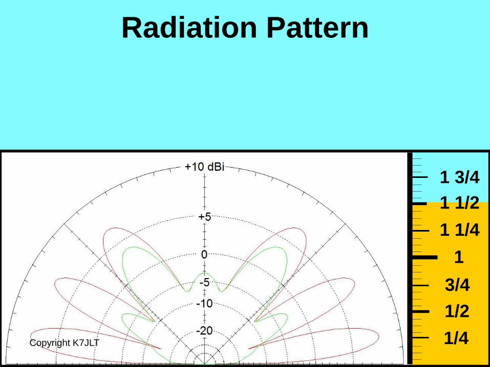
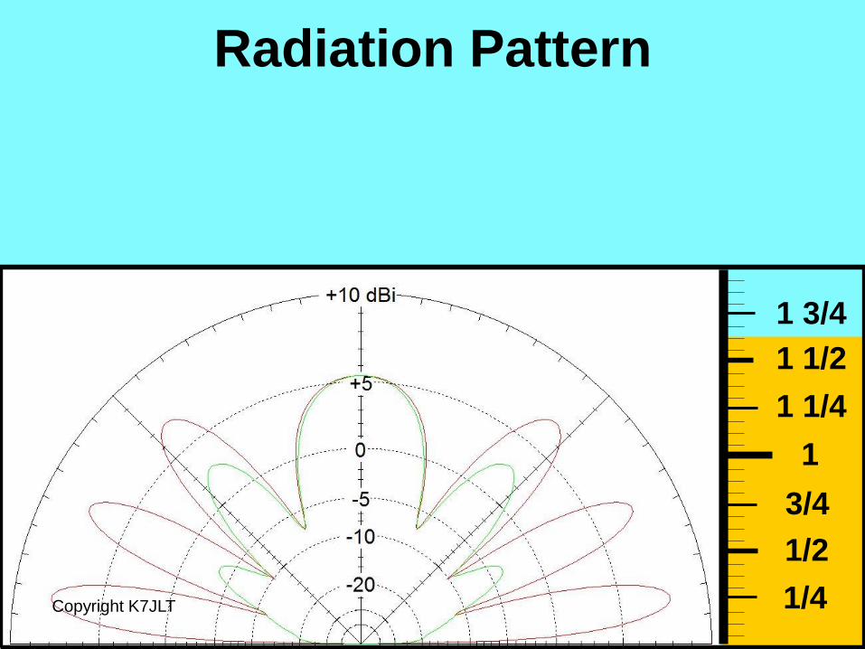
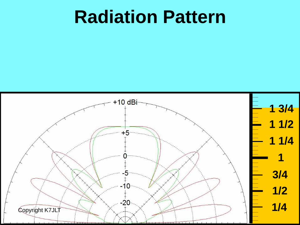
What is going
on?
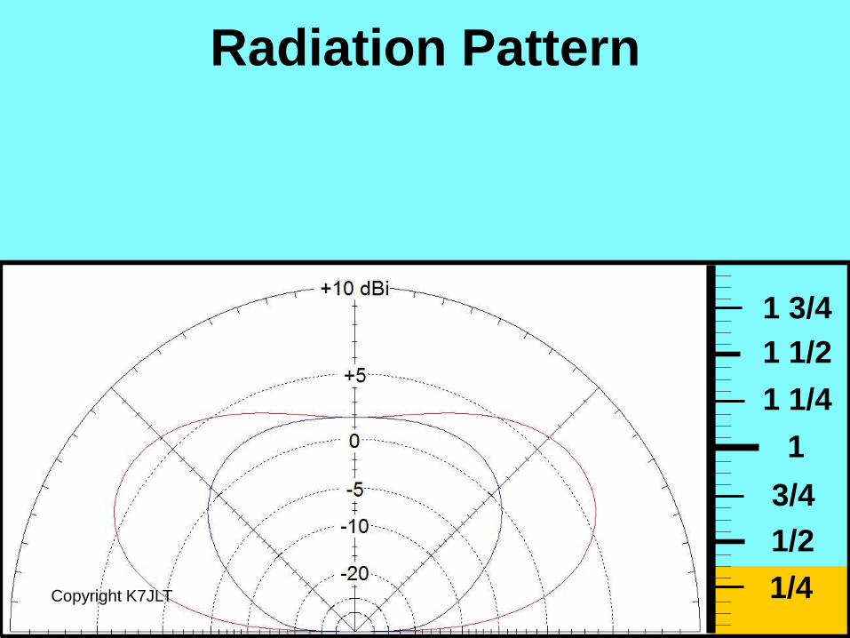
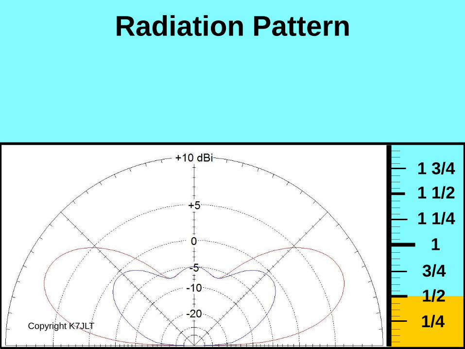
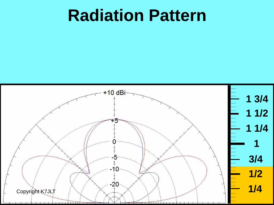
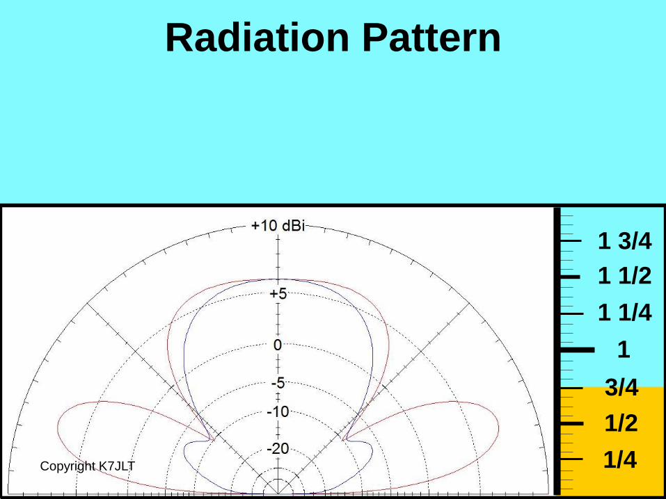
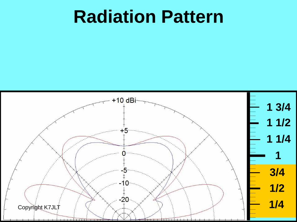
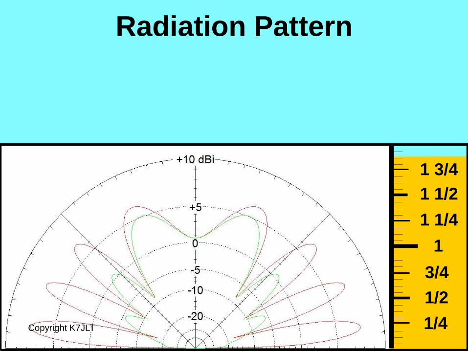
Remember from the
Dipole Tutorial #2 how
antenna lobs changed as
elevation increased?
Copyright K7JLT 78
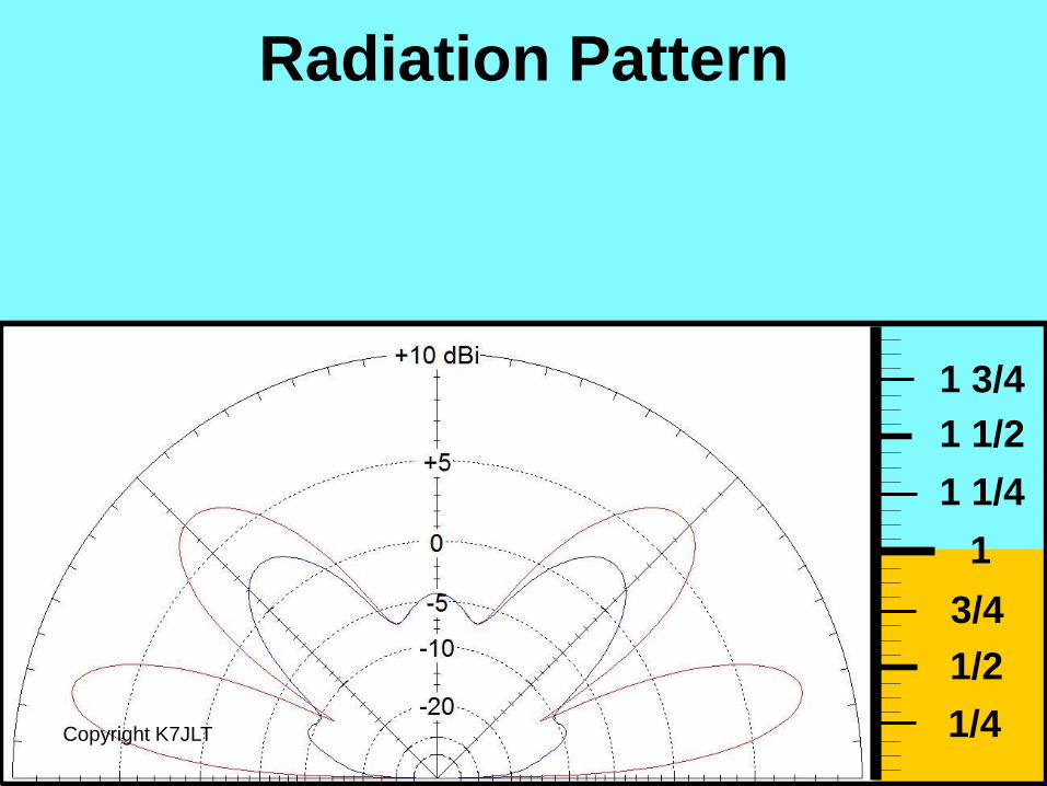
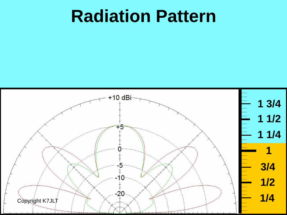
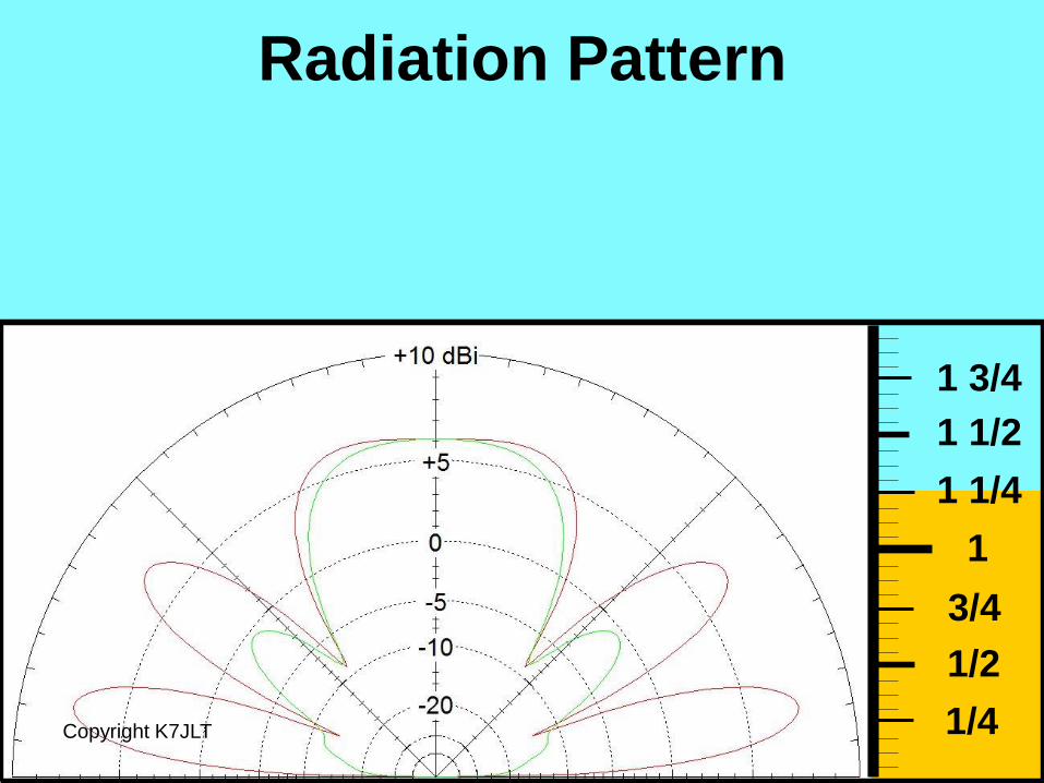
Here’s a quick review
of the Dipole Tutorial
height slides.
Copyright K7JLT 79
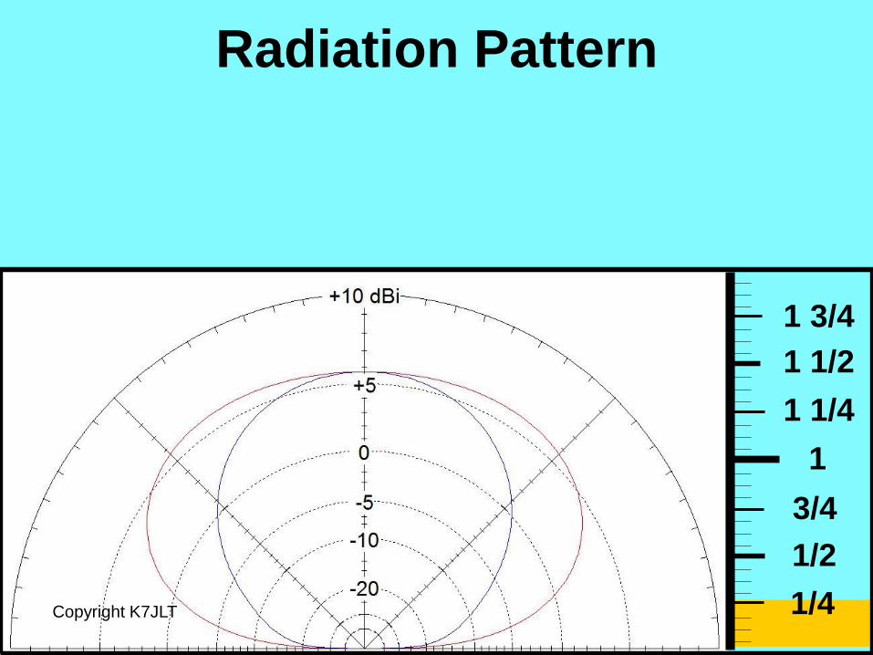
1/4
1/2
3/4
1
1 1/4
1 1/2
1 3/4
Radiation Pattern
Copyright K7JLT
1/4
1/2
3/4
1
1 1/4
1 1/2
1 3/4
Radiation Pattern
Copyright K7JLT
1/4
1/2
3/4
1
1 1/4
1 1/2
1 3/4
Radiation Pattern
Copyright K7JLT
Radiation Pattern
1/4
1/2
3/4
1
1 1/4
1 1/2
1 3/4
Copyright K7JLT
1/4
1/2
3/4
1
1 1/4
1 1/2
1 3/4
Radiation Pattern
Copyright K7JLT
1/4
1/2
3/4
1
1 1/4
1 1/2
1 3/4
Radiation Pattern
Copyright K7JLT
1/4
1/2
3/4
1
1 1/4
1 1/2
1 3/4
Radiation Pattern
Copyright K7JLT
1/4
1/2
3/4
1
1 1/4
1 1/2
1 3/4
Radiation Pattern
Copyright K7JLT
1/4
1/2
3/4
1
1 1/4
1 1/2
1 3/4
Radiation Pattern
Copyright K7JLT
1/4
1/2
3/4
1
1 1/4
1 1/2
1 3/4
Radiation Pattern
Copyright K7JLT
1/4
1/2
3/4
1
1 1/4
1 1/2
1 3/4
Radiation Pattern
Copyright K7JLT
Radiation Pattern
1/4
1/2
3/4
1
1 1/4
1 1/2
1 3/4
Copyright K7JLT
1/4
1/2
3/4
1
1 1/4
1 1/2
1 3/4
Radiation Pattern
Copyright K7JLT
1/4
1/2
3/4
1
1 1/4
1 1/2
1 3/4
Radiation Pattern
Copyright K7JLT
1/4
1/2
3/4
1
1 1/4
1 1/2
1 3/4
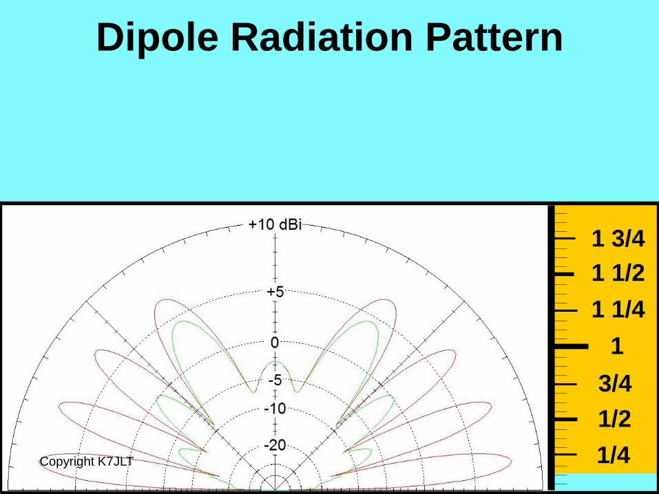
Dipole Radiation Pattern
Copyright K7JLT
1/4
1/2
3/4
1
1 1/4
1 1/2
1 3/4
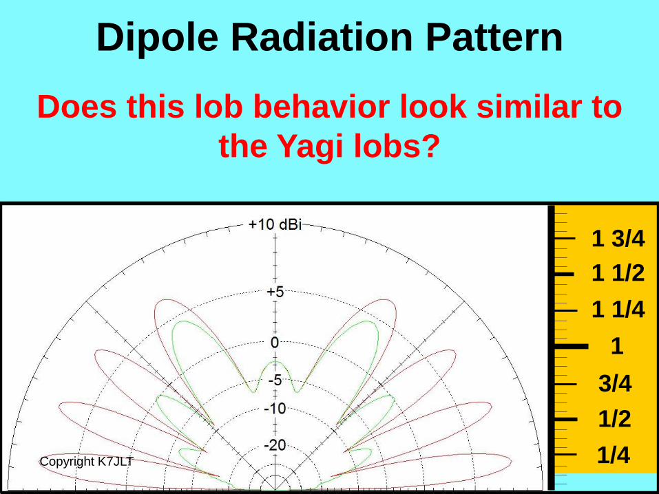
Dipole Radiation Pattern
Copyright K7JLT
Does this lob behavior look similar to
the Yagi lobs?

2 Element 20 Meter Yagi
Copyright K7JLT 96
1/2
3/4
1
1 1/4
1 1/2
1 3/4
At 100 Feet
Dipole @ 100 Feet
It’s a Match!
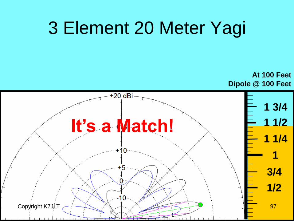
3 Element 20 Meter Yagi
Copyright K7JLT 97
1/2
3/4
1
1 1/4
1 1/2
1 3/4
At 100 Feet
Dipole @ 100 Feet
It’s a Match!
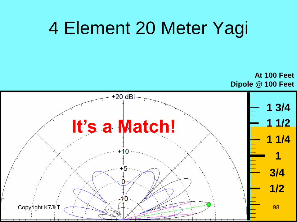
4 Element 20 Meter Yagi
Copyright K7JLT 98
1/2
3/4
1
1 1/4
1 1/2
1 3/4
At 100 Feet
Dipole @ 100 Feet
It’s a Match!
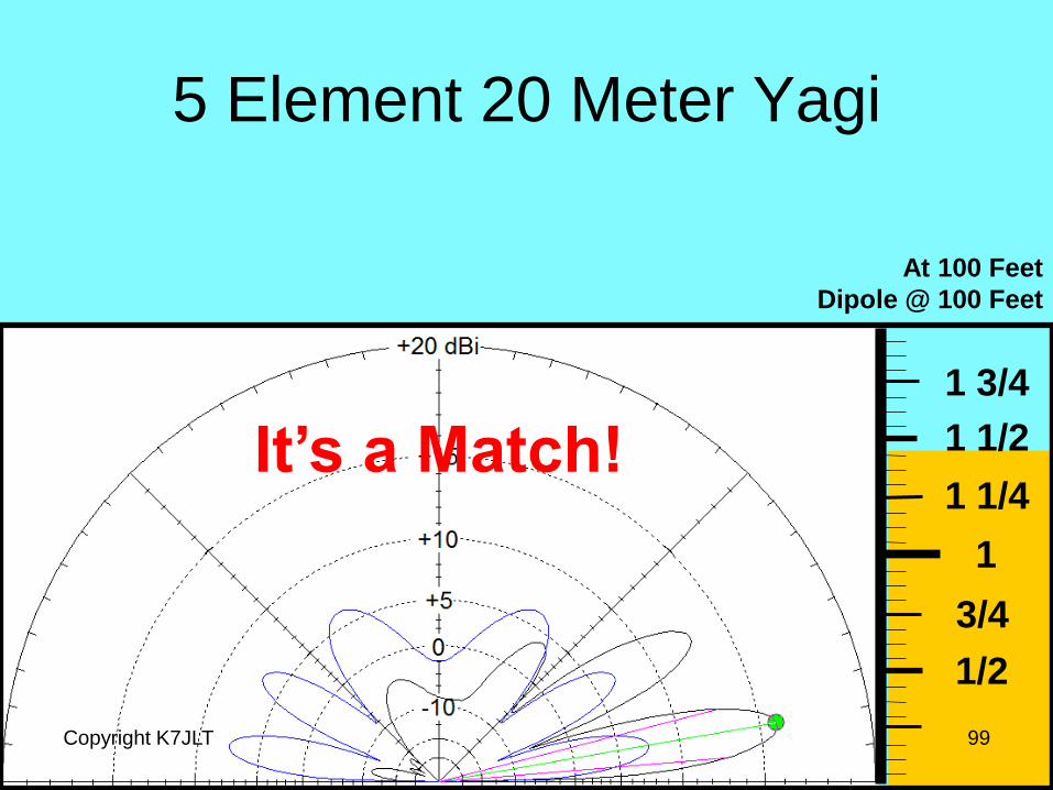
5 Element 20 Meter Yagi
Copyright K7JLT 99
1/2
3/4
1
1 1/4
1 1/2
1 3/4
At 100 Feet
Dipole @ 100 Feet
It’s a Match!
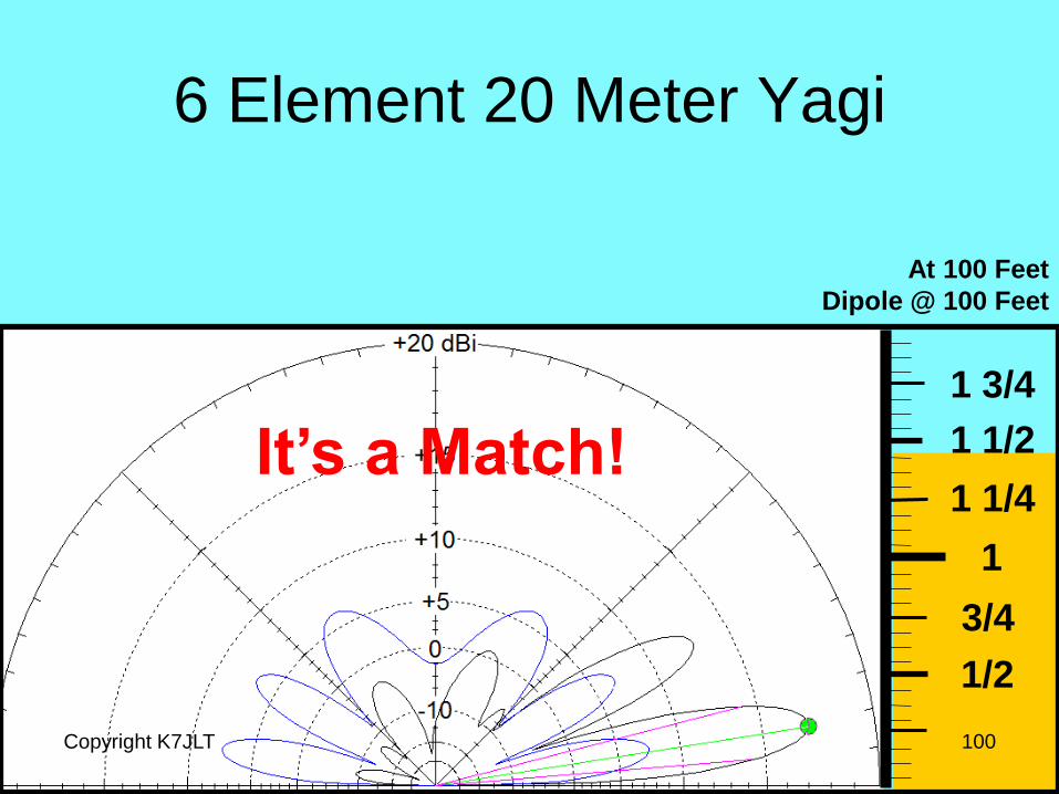
6 Element 20 Meter Yagi
Copyright K7JLT 100
1/2
3/4
1
1 1/4
1 1/2
1 3/4
At 100 Feet
Dipole @ 100 Feet
It’s a Match!
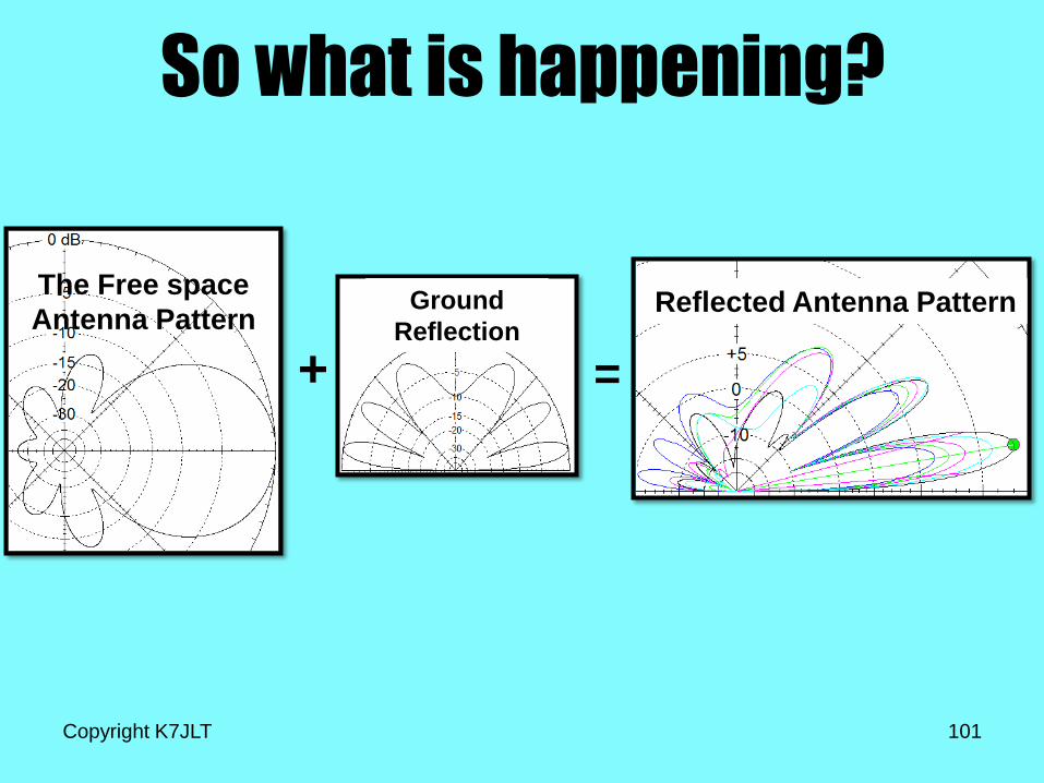
So what is happening?
Copyright K7JLT 101
The Free space
Antenna Pattern
+
Ground
Reflection
=
Reflected Antenna Pattern
Yagi General Rules of Thumb • Yagi antennas have similar radiation elevation lob
patterns for a single height, just the gain of the
main lob changes with the number of elements.
Copyright K7JLT 102
What happens to the antenna
patterns on different frequency
bands?
Copyright K7JLT 103
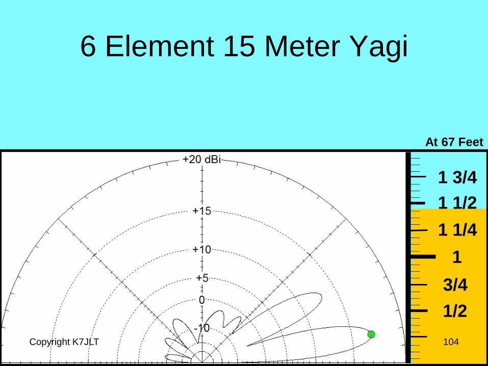
6 Element 15 Meter Yagi
Copyright K7JLT 104
1/2
3/4
1
1 1/4
1 1/2
1 3/4
At 67 Feet
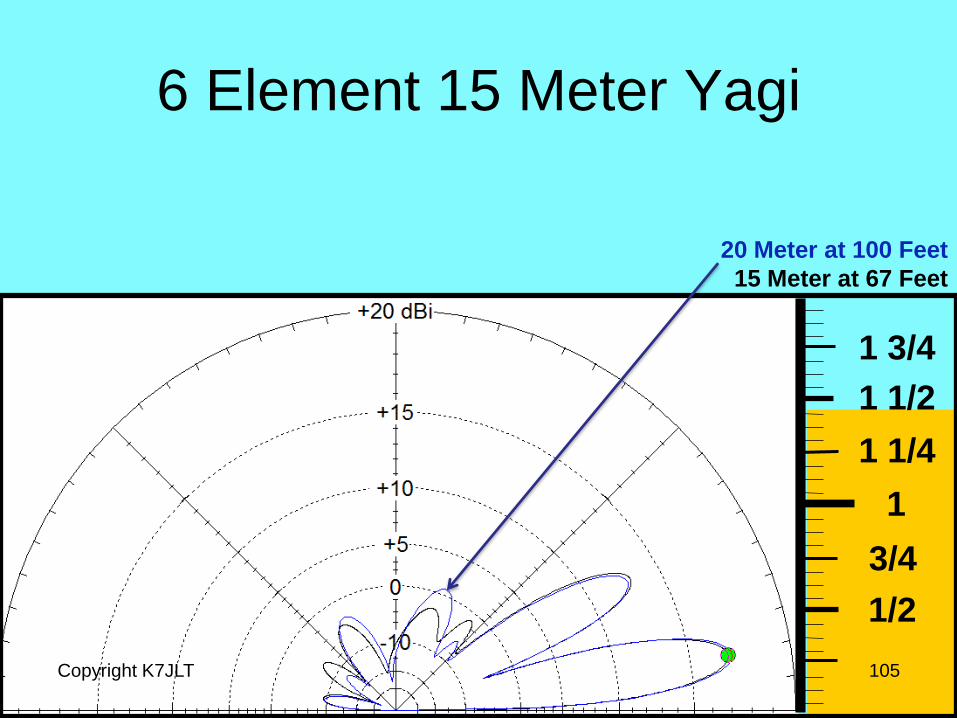
6 Element 15 Meter Yagi
Copyright K7JLT 105
1/2
3/4
1
1 1/4
1 1/2
1 3/4
20 Meter at 100 Feet
15 Meter at 67 Feet

6 Element 15 Meter Yagi
Copyright K7JLT 106
1/2
3/4
1
1 1/4
1 1/2
1 3/4
At 50 Feet

6 Element 10 Meter Yagi
Copyright K7JLT 107
1/2
3/4
1
1 1/4
1 1/2
1 3/4
20 Meter at 100 Feet
10 Meter at 50 Feet
Yagi General Rules of Thumb • Yagi antennas have similar radiation elevation lob
patterns for a single height, just the gain of the
main lob changes with the number of elements.
• When height is measured in wavelengths, there is
minimal differences between elevation lobs of
Yagis with the same number of elements on
different bands.
Copyright K7JLT 108
What about the Azimuth
Pattern?
Copyright K7JLT 109
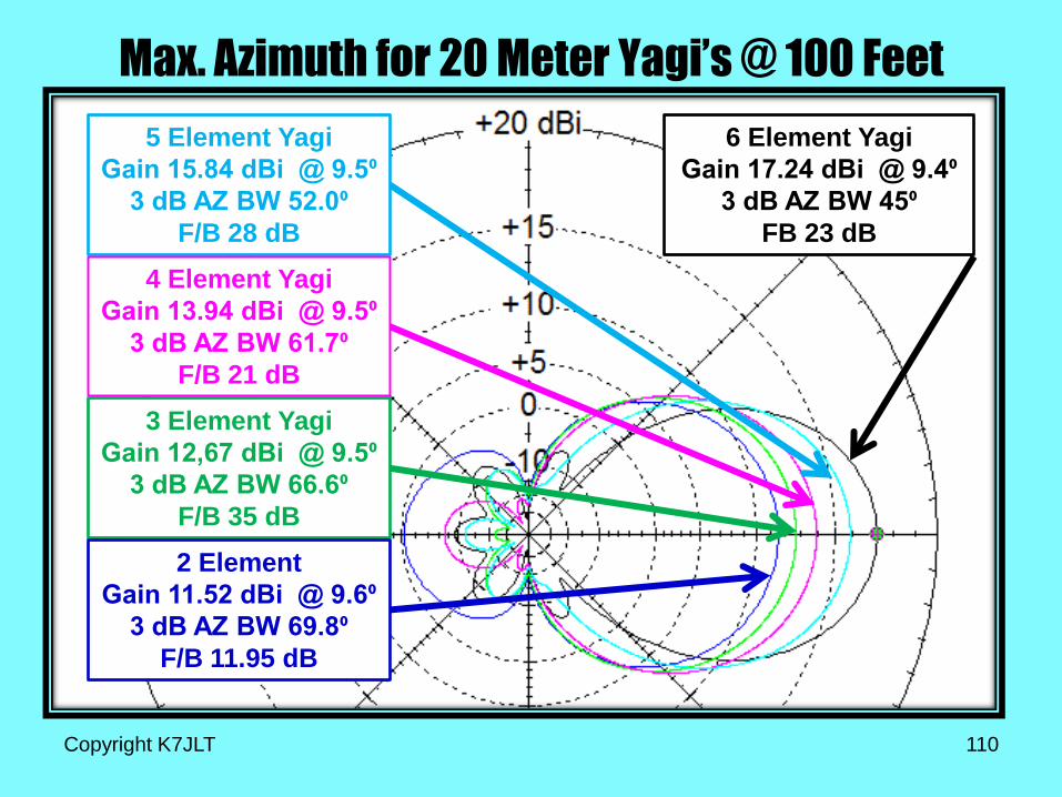
Max. Azimuth for 20 Meter Yagi’s @ 100 Feet
Copyright K7JLT 110
6 Element Yagi
Gain 17.24 dBi @ 9.4⁰
3 dB AZ BW 45⁰
FB 23 dB
5 Element Yagi
Gain 15.84 dBi @ 9.5⁰
3 dB AZ BW 52.0⁰
F/B 28 dB
4 Element Yagi
Gain 13.94 dBi @ 9.5⁰
3 dB AZ BW 61.7⁰
F/B 21 dB
3 Element Yagi
Gain 12,67 dBi @ 9.5⁰
3 dB AZ BW 66.6⁰
F/B 35 dB
2 Element
Gain 11.52 dBi @ 9.6⁰
3 dB AZ BW 69.8⁰
F/B 11.95 dB
Yagi General Rules of Thumb • Yagi antennas have similar radiation elevation lob
patterns for a single height, just the gain of the
main lob changes with the number of elements.
• When height is measured in wavelengths, there is
minimal differences between elevation lobs of
Yagis with the same number of elements on
different bands.
• The primary Azimuth Lob narrows as additional
elements are added to the array.
Copyright K7JLT 111
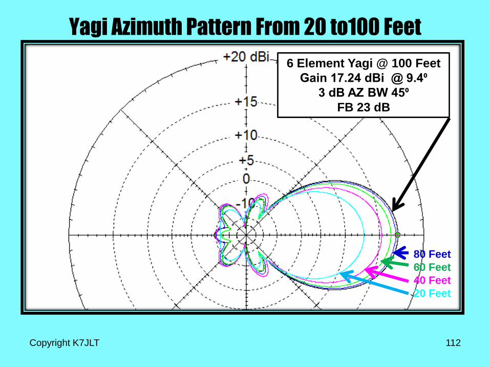
Yagi Azimuth Pattern From 20 to100 Feet
Copyright K7JLT 112
6 Element Yagi @ 100 Feet
Gain 17.24 dBi @ 9.4⁰
3 dB AZ BW 45⁰
FB 23 dB
80 Feet
60 Feet
40 Feet
20 Feet
Yagi General Rules of Thumb • Yagi antennas have similar radiation elevation lob
patterns for a single height, just the gain of the
main lob changes with the number of elements.
• When height is measured in wavelengths, there is
minimal differences between elevation lobs of
Yagis with the same number of elements on
different bands.
• The primary Azimuth Lob narrows as additional
elements are added to the array.
• As the height of a Yagi increases the Azimuth Lob broadens.
Copyright K7JLT 113
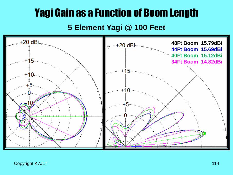
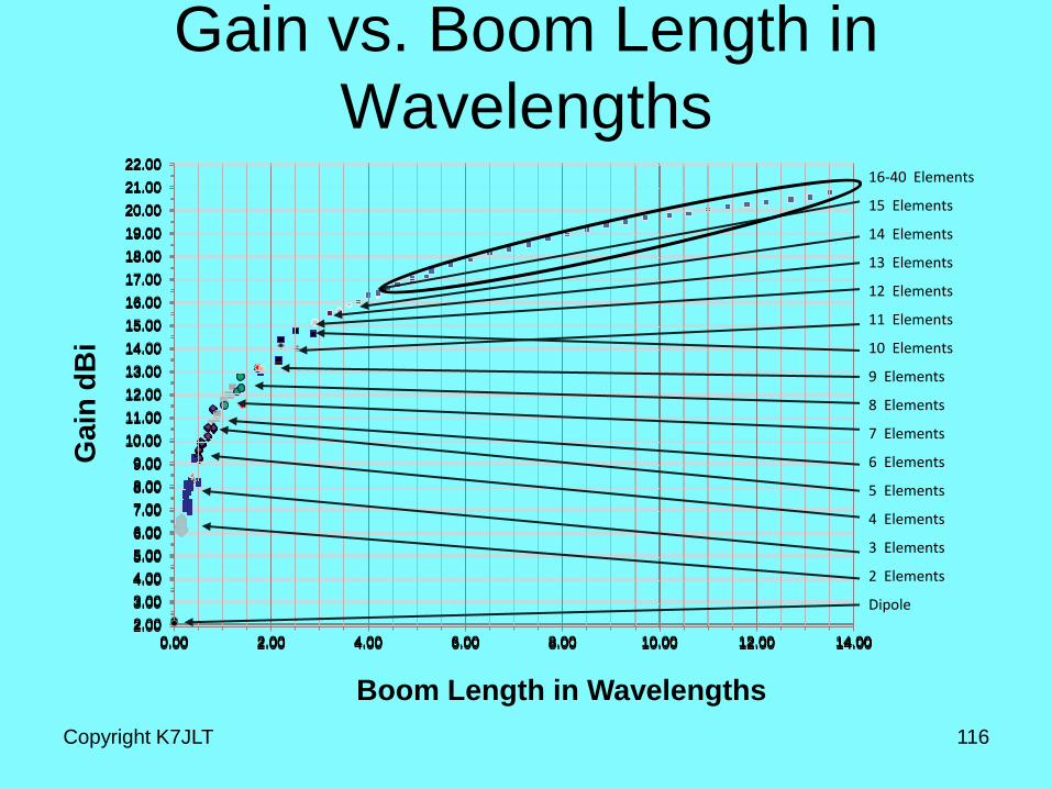
Yagi Gain as a Function of Boom Length
Copyright K7JLT 114
5 Element Yagi @ 100 Feet
48Ft Boom 15.79dBi
44Ft Boom 15.69dBi
40Ft Boom 15.12dBi
34Ft Boom 14.82dBi
Yagi Gain
Copyright K7JLT 115
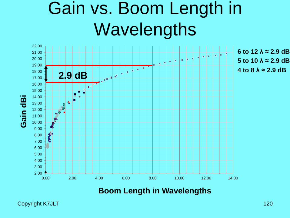
We have seen that Yagi Gain increases
as the boom length is increased.
Is there some rule of thumb equating
boom length to gain?
I looked at the gain vs. boom length in
wavelengths for 105 different Yagi’s
designed for 40 meters up to 70
centimeters and here is the result.
2.00
3.00
4.00
5.00
6.00
7.00
8.00
9.00
10.00
11.00
12.00
13.00
14.00
15.00
16.00
17.00
18.00
19.00
20.00
21.00
22.00
0.00 2.00 4.00 6.00 8.00 10.00 12.00 14.00
2.00
3.00
4.00
5.00
6.00
7.00
8.00
9.00
10.00
11.00
12.00
13.00
14.00
15.00
16.00
17.00
18.00
19.00
20.00
21.00
22.00
0.00 2.00 4.00 6.00 8.00 10.00 12.00 14.00
2.00
3.00
4.00
5.00
6.00
7.00
8.00
9.00
10.00
11.00
12.00
13.00
14.00
15.00
16.00
17.00
18.00
19.00
20.00
21.00
22.00
0.00 2.00 4.00 6.00 8.00 10.00 12.00 14.00
Gain vs. Boom Length in
Wavelengths
Copyright K7JLT 116
Boom Length in Wavelengths
Ga
in d
Bi
2.00
3.00
4.00
5.00
6.00
7.00
8.00
9.00
10.00
11.00
12.00
13.00
14.00
15.00
16.00
17.00
18.00
19.00
20.00
21.00
22.00
0.00 2.00 4.00 6.00 8.00 10.00 12.00 14.00 2.00
3.00
4.00
5.00
6.00
7.00
8.00
9.00
10.00
11.00
12.00
13.00
14.00
15.00
16.00
17.00
18.00
19.00
20.00
21.00
22.00
0.00 2.00 4.00 6.00 8.00 10.00 12.00 14.00
16-40 Elements
15 Elements
14 Elements
13 Elements
12 Elements
11 Elements
10 Elements
9 Elements
8 Elements
7 Elements
6 Elements
5 Elements
4 Elements
3 Elements
2 Elements
Dipole
2.00
3.00
4.00
5.00
6.00
7.00
8.00
9.00
10.00
11.00
12.00
13.00
14.00
15.00
16.00
17.00
18.00
19.00
20.00
21.00
22.00
0.00 2.00 4.00 6.00 8.00 10.00 12.00 14.00
2.00
3.00
4.00
5.00
6.00
7.00
8.00
9.00
10.00
11.00
12.00
13.00
14.00
15.00
16.00
17.00
18.00
19.00
20.00
21.00
22.00
0.00 2.00 4.00 6.00 8.00 10.00 12.00 14.00
2.00
3.00
4.00
5.00
6.00
7.00
8.00
9.00
10.00
11.00
12.00
13.00
14.00
15.00
16.00
17.00
18.00
19.00
20.00
21.00
22.00
0.00 2.00 4.00 6.00 8.00 10.00 12.00 14.00
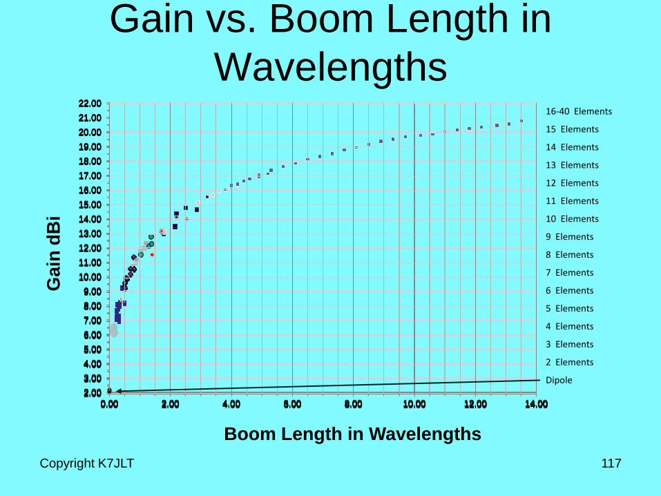
Gain vs. Boom Length in
Wavelengths
Copyright K7JLT 117
Boom Length in Wavelengths
Ga
in d
Bi
2.00
3.00
4.00
5.00
6.00
7.00
8.00
9.00
10.00
11.00
12.00
13.00
14.00
15.00
16.00
17.00
18.00
19.00
20.00
21.00
22.00
0.00 2.00 4.00 6.00 8.00 10.00 12.00 14.00 2.00
3.00
4.00
5.00
6.00
7.00
8.00
9.00
10.00
11.00
12.00
13.00
14.00
15.00
16.00
17.00
18.00
19.00
20.00
21.00
22.00
0.00 2.00 4.00 6.00 8.00 10.00 12.00 14.00
16-40 Elements
15 Elements
14 Elements
13 Elements
12 Elements
11 Elements
10 Elements
9 Elements
8 Elements
7 Elements
6 Elements
5 Elements
4 Elements
3 Elements
2 Elements
Dipole
2.00
3.00
4.00
5.00
6.00
7.00
8.00
9.00
10.00
11.00
12.00
13.00
14.00
15.00
16.00
17.00
18.00
19.00
20.00
21.00
22.00
0.00 2.00 4.00 6.00 8.00 10.00 12.00 14.00
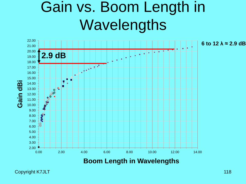
Gain vs. Boom Length in
Wavelengths
Copyright K7JLT 118
Boom Length in Wavelengths
Ga
in d
Bi
2.9 dB
6 to 12 λ ≈ 2.9 dB
2.00
3.00
4.00
5.00
6.00
7.00
8.00
9.00
10.00
11.00
12.00
13.00
14.00
15.00
16.00
17.00
18.00
19.00
20.00
21.00
22.00
0.00 2.00 4.00 6.00 8.00 10.00 12.00 14.00
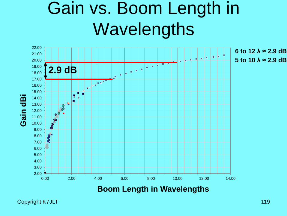
Gain vs. Boom Length in
Wavelengths
Copyright K7JLT 119
Boom Length in Wavelengths
Ga
in d
Bi
2.9 dB
6 to 12 λ ≈ 2.9 dB
5 to 10 λ ≈ 2.9 dB
2.00
3.00
4.00
5.00
6.00
7.00
8.00
9.00
10.00
11.00
12.00
13.00
14.00
15.00
16.00
17.00
18.00
19.00
20.00
21.00
22.00
0.00 2.00 4.00 6.00 8.00 10.00 12.00 14.00
Gain vs. Boom Length in
Wavelengths
Copyright K7JLT 120
Boom Length in Wavelengths
Ga
in d
Bi
2.9 dB
6 to 12 λ ≈ 2.9 dB
5 to 10 λ ≈ 2.9 dB
4 to 8 λ ≈ 2.9 dB
2.00
3.00
4.00
5.00
6.00
7.00
8.00
9.00
10.00
11.00
12.00
13.00
14.00
15.00
16.00
17.00
18.00
19.00
20.00
21.00
22.00
0.00 2.00 4.00 6.00 8.00 10.00 12.00 14.00
Gain vs. Boom Length in
Wavelengths
Copyright K7JLT 121
Boom Length in Wavelengths
Ga
in d
Bi
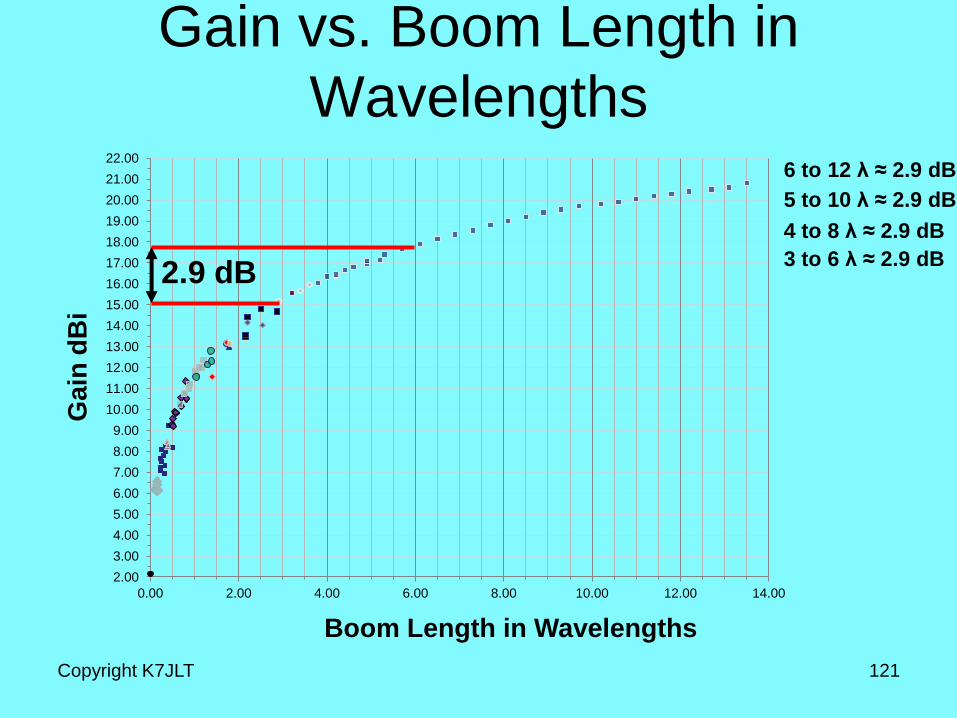
2.9 dB 3 to 6 λ ≈ 2.9 dB
6 to 12 λ ≈ 2.9 dB
5 to 10 λ ≈ 2.9 dB
4 to 8 λ ≈ 2.9 dB
2.00
3.00
4.00
5.00
6.00
7.00
8.00
9.00
10.00
11.00
12.00
13.00
14.00
15.00
16.00
17.00
18.00
19.00
20.00
21.00
22.00
0.00 2.00 4.00 6.00 8.00 10.00 12.00 14.00
Gain vs. Boom Length in
Wavelengths
Copyright K7JLT 122
Boom Length in Wavelengths
Ga
in d
Bi
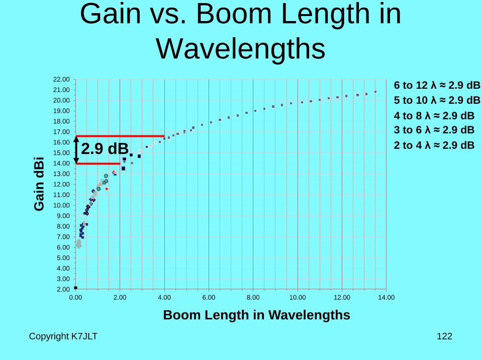
2.9 dB 2 to 4 λ ≈ 2.9 dB
3 to 6 λ ≈ 2.9 dB
6 to 12 λ ≈ 2.9 dB
5 to 10 λ ≈ 2.9 dB
4 to 8 λ ≈ 2.9 dB
2.00
3.00
4.00
5.00
6.00
7.00
8.00
9.00
10.00
11.00
12.00
13.00
14.00
15.00
16.00
17.00
18.00
19.00
20.00
21.00
22.00
0.00 2.00 4.00 6.00 8.00 10.00 12.00 14.00
Gain vs. Boom Length in
Wavelengths
Copyright K7JLT 123
Boom Length in Wavelengths
Ga
in d
Bi
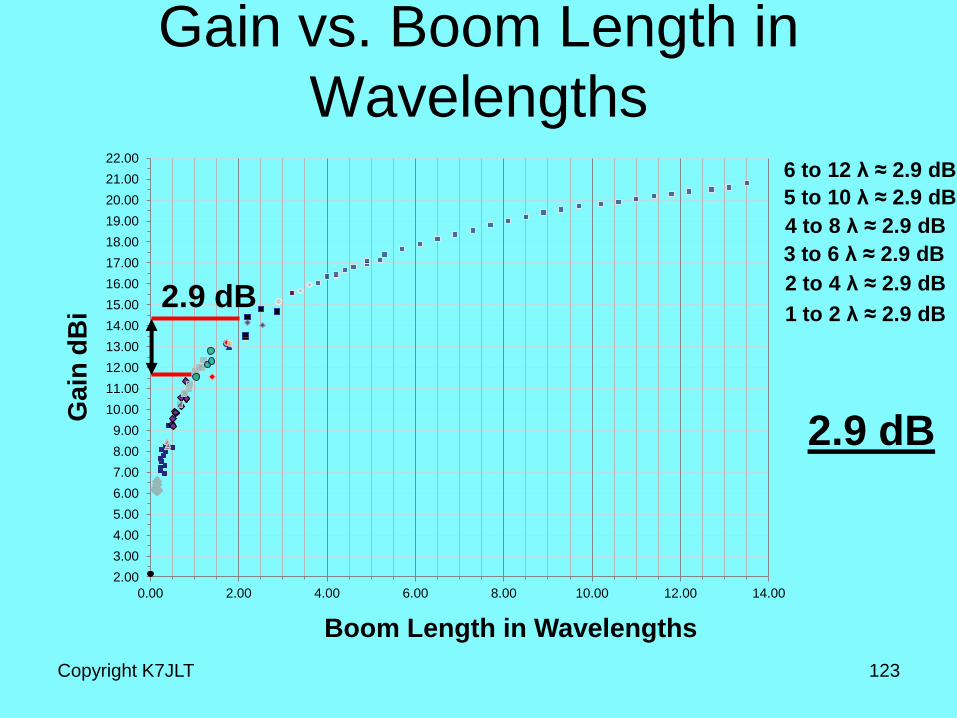
2.9 dB 1 to 2 λ ≈ 2.9 dB
2 to 4 λ ≈ 2.9 dB
3 to 6 λ ≈ 2.9 dB
6 to 12 λ ≈ 2.9 dB
5 to 10 λ ≈ 2.9 dB
4 to 8 λ ≈ 2.9 dB
2.9 dB
Yagi General Rules of Thumb
• As the Yagi Boom Length increases, Antenna gain
increases by ≈ 3dB for every doubling of length.
Copyright K7JLT 124
(Continued)
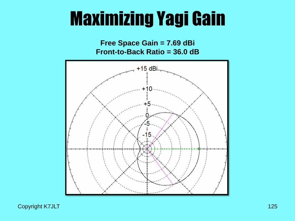
Maximizing Yagi Gain
Copyright K7JLT 125
Free Space Gain = 7.69 dBi
Front-to-Back Ratio = 36.0 dB
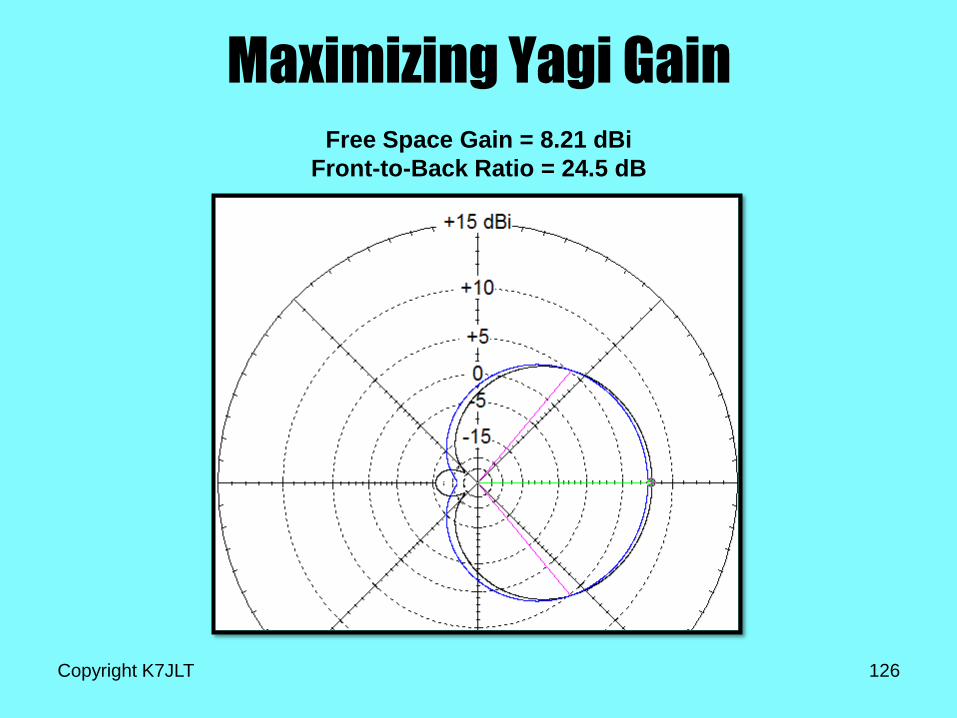
Maximizing Yagi Gain
Copyright K7JLT 126
Free Space Gain = 8.21 dBi
Front-to-Back Ratio = 24.5 dB
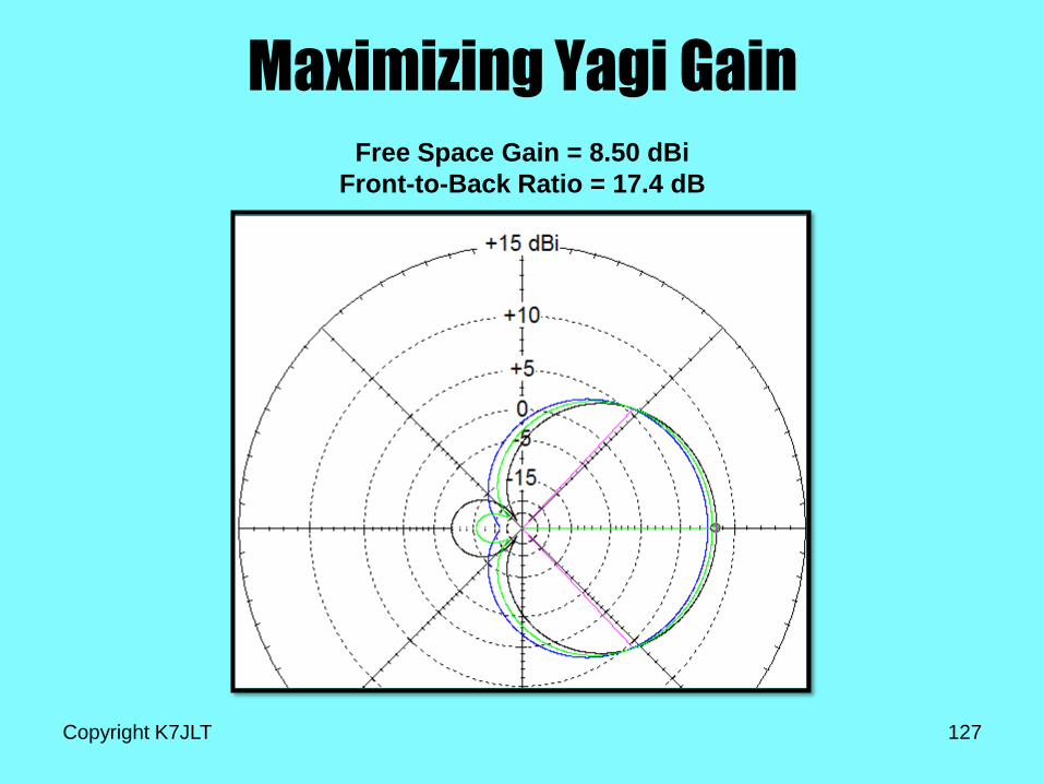
Maximizing Yagi Gain
Copyright K7JLT 127
Free Space Gain = 8.50 dBi
Front-to-Back Ratio = 17.4 dB
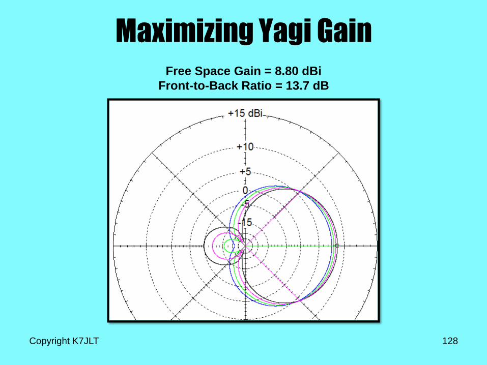
Maximizing Yagi Gain
Copyright K7JLT 128
Free Space Gain = 8.80 dBi
Front-to-Back Ratio = 13.7 dB
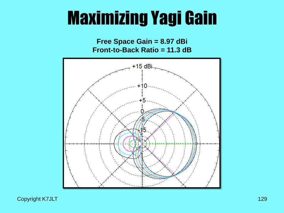
Maximizing Yagi Gain
Copyright K7JLT 129
Free Space Gain = 8.97 dBi
Front-to-Back Ratio = 11.3 dB
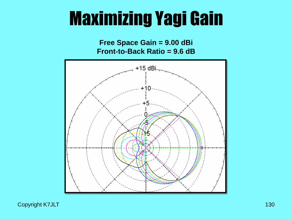
Maximizing Yagi Gain
Copyright K7JLT 130
Free Space Gain = 9.00 dBi
Front-to-Back Ratio = 9.6 dB
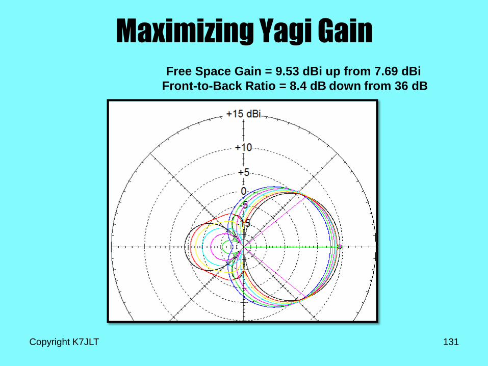
Maximizing Yagi Gain
Copyright K7JLT 131
Free Space Gain = 9.53 dBi
Front-to-Back Ratio = 8.4 dB
up from 7.69 dBi
down from 36 dB
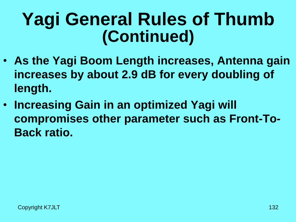
Yagi General Rules of Thumb
• As the Yagi Boom Length increases, Antenna gain
increases by about 2.9 dB for every doubling of
length.
• Increasing Gain in an optimized Yagi will
compromises other parameter such as Front-To-
Back ratio.
Copyright K7JLT 132
(Continued)

Can we get more gain by stacking two
Yagis and what else happens?
Copyright K7JLT 133
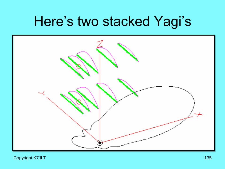
Here’s two stacked Yagi’s
Copyright K7JLT 135
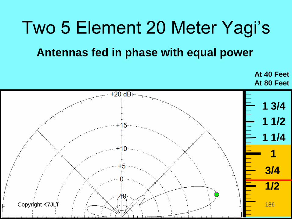
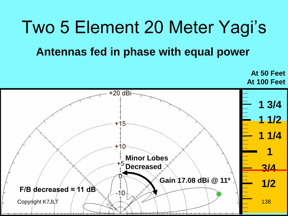
Two 5 Element 20 Meter Yagi’s
Copyright K7JLT 136
1/2
3/4
1
1 1/4
1 1/2
1 3/4
At 40 Feet
At 80 Feet
Antennas fed in phase with equal power
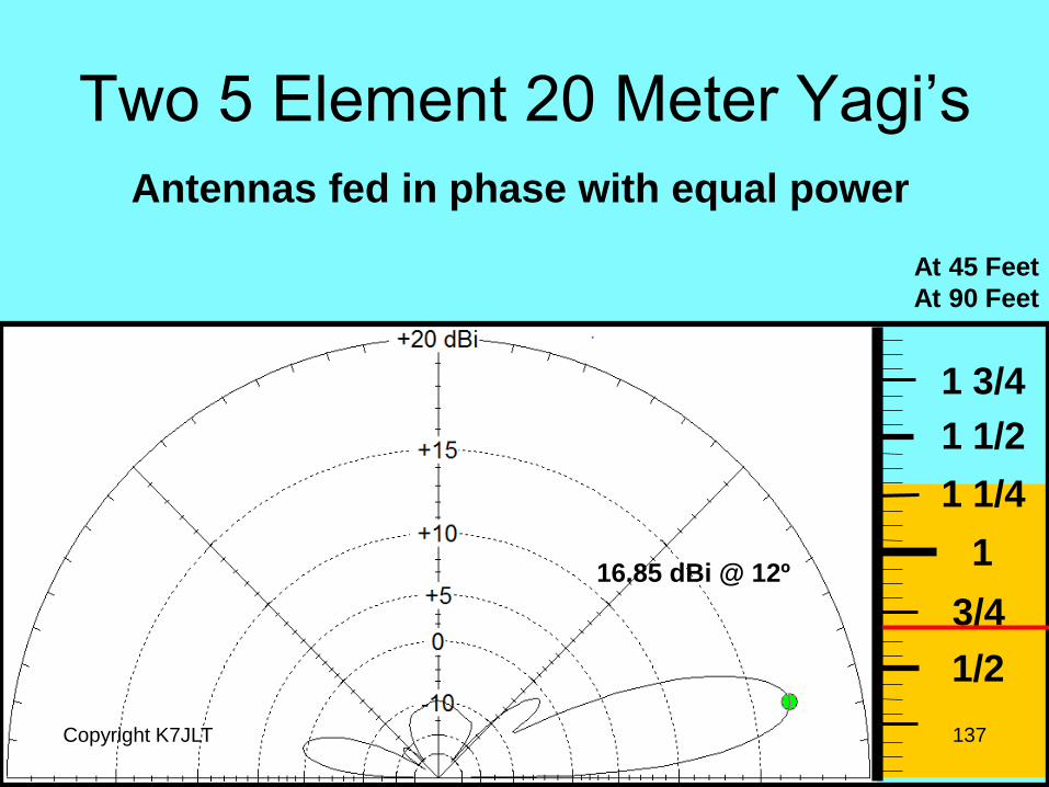
Two 5 Element 20 Meter Yagi’s
Copyright K7JLT 137
1/2
3/4
1
1 1/4
1 1/2
1 3/4
At 45 Feet
At 90 Feet
Antennas fed in phase with equal power
16.85 dBi @ 12º
Two 5 Element 20 Meter Yagi’s
Copyright K7JLT 138
1/2
3/4
1
1 1/4
1 1/2
1 3/4
At 50 Feet
At 100 Feet
Antennas fed in phase with equal power
Gain 17.08 dBi @ 11º
F/B decreased ≈ 11 dB
Minor Lobes
Decreased
Yagi General Rules of Thumb
• As the Yagi Boom Length is increased Antenna
gain increases.
• Increasing Gain in an optimized Yagi always
compromises some other parameter such as
Front-To-Back ratio.
• Adding a second identical parallel Yagi increases
gain a small amount and changes the pattern.
Copyright K7JLT 140
(Continued)
If we need radiation at a
different angle, can we just use
one of the antennas?
Copyright K7JLT 141
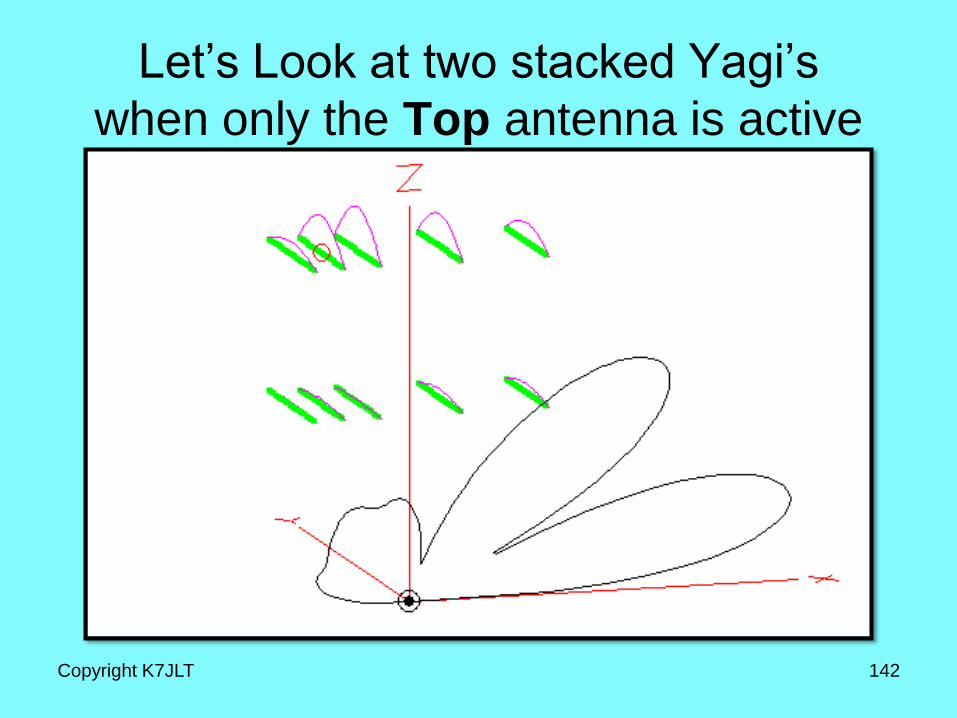
Let’s Look at two stacked Yagi’s
when only the Top antenna is active
Copyright K7JLT 142
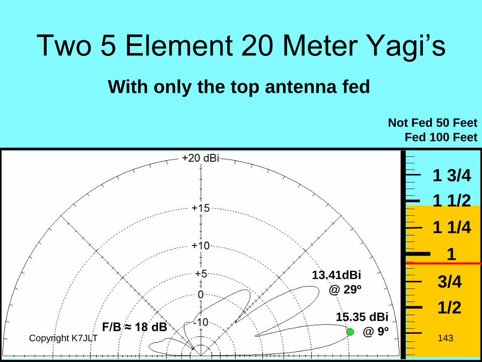
Two 5 Element 20 Meter Yagi’s
Copyright K7JLT 143
1/2
3/4
1
1 1/4
1 1/2
1 3/4
Not Fed 50 Feet
Fed 100 Feet
With only the top antenna fed
15.35 dBi
@ 9º
13.41dBi
@ 29º
F/B ≈ 18 dB
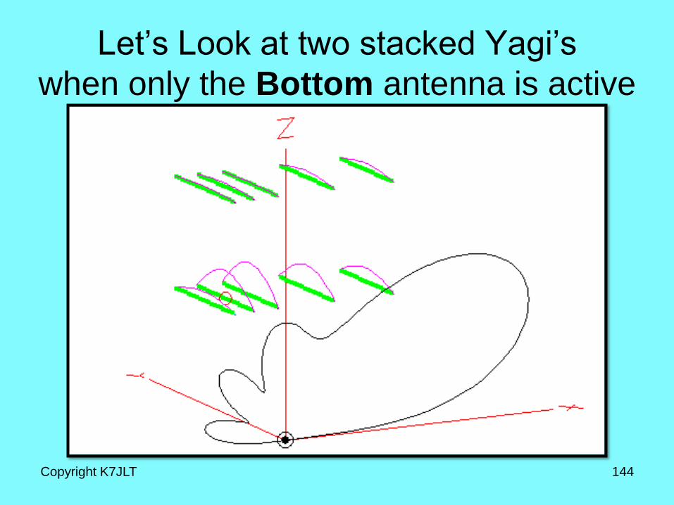
Let’s Look at two stacked Yagi’s
when only the Bottom antenna is active
Copyright K7JLT 144
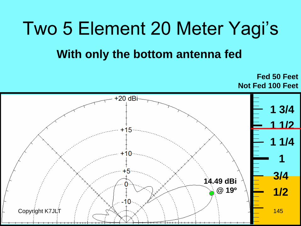
Two 5 Element 20 Meter Yagi’s
Copyright K7JLT 145
1/2
3/4
1
1 1/4
1 1/2
1 3/4
Fed 50 Feet
Not Fed 100 Feet
With only the bottom antenna fed
14.49 dBi
@ 19º
What is happening?
Copyright K7JLT 146
Mutual Coupling is
effecting the antenna
patterns!
Yagi General Rules of Thumb
• As the Yagi Boom Length is increased Antenna
gain increases.
• Increasing Gain in an optimized Yagi always
compromises some other parameter such as
Front-To-Back ratio.
• Adding a second identical parallel Yagi increases
gain only a small amount but changes the pattern.
• Mutual coupling between two parallel antennas
changes the radiation pattern of each antenna.
Copyright K7JLT 147
(Continued)
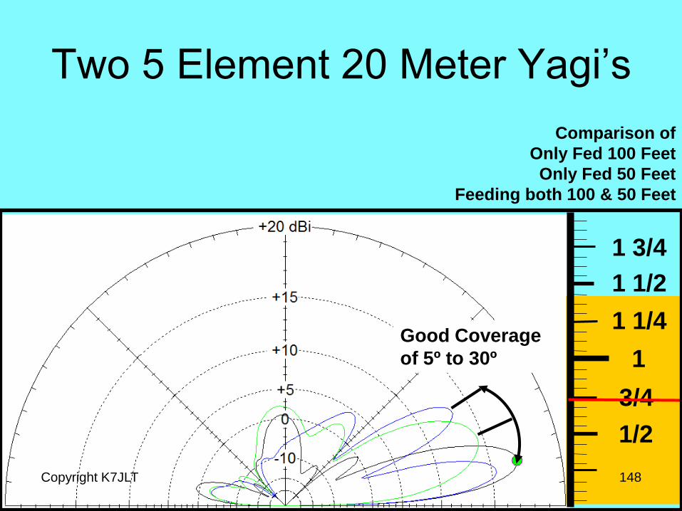
Two 5 Element 20 Meter Yagi’s
Copyright K7JLT 148
1/2
3/4
1
1 1/4
1 1/2
1 3/4
Comparison of
Only Fed 100 Feet
Only Fed 50 Feet
Feeding both 100 & 50 Feet
Good Coverage
of 5º to 30º
Yagi General Rules of Thumb
• Coverage of a wide range of angles is possible
with multiple antennas even with the occurrence
of mutual coupling.
• Care must be taken when adding other antennas
to a tower containing a Yagi (such as a 40 meter
dipole which also resonates on 15 meters)
because it will distort the Yagi’s antenna pattern.
Copyright K7JLT 149
(Continued)
Copyright K7JLT 150
End of Tutorial


