General rights Copyright and moral rights for the publications made accessible in the public portal are retained by the authors and/or other copyright owners and it is a condition of accessing publications that users recognise and abide by the legal requirements associated with these rights.
Users may download and print one copy of any publication from the public portal for the purpose of private study or research.
You may not further distribute the material or use it for any profit-making activity or commercial gain
You may freely distribute the URL identifying the publication in the public portal If you believe that this document breaches copyright please contact us providing details, and we will remove access to the work immediately and investigate your claim.
Downloaded from orbit.dtu.dk on: May 01, 2020
X-ray coherent diffraction imaging with an objective lens: towards 3D mapping of thickpolycrystals
Pedersen, Anders Filsøe; Chamard, Virginie ; Detlefs, Carsten; Zhou, Tao ; Carbone, Dina ; Poulsen,Henning FriisPublished in:Physical Review Letters
Publication date:2020
Document VersionEarly version, also known as pre-print
Link back to DTU Orbit
Citation (APA):Pedersen, A. F., Chamard, V., Detlefs, C., Zhou, T., Carbone, D., & Poulsen, H. F. (2020). X-ray coherentdiffraction imaging with an objective lens: towards 3D mapping of thick polycrystals. Manuscript submitted forpublication.

1
X-ray coherent diffraction imaging with an objective lens: towards 3D
mapping of thick polycrystals
Anders Filsøe Pedersen1, Virginie Chamard2, Carsten Detlefs3, Tao Zhou3, Dina Carbone4,
Henning Friis Poulsen1*
1: Department of Physics, Technical University of Denmark, 2800 Kongens Lyngby, Denmark
2: Aix Marseille Univ, CNRS, Centrale Marseille, Institut Fresnel, Marseille, France
3: European Synchrotron Radiation Facility, 71 Avenue des Martyrs, 38000 Grenoble, France
4: MAX IV Laboratory, Fotongatan 2, 225 92 Lund, Sweden
*: corresponding author, [email protected]
This article is under consideration in a research journal.
Abstract We report on a new x-ray imaging method, which combines the high spatial resolution of
coherent diffraction imaging with the ability of dark field microscopy to map grains within thick
polycrystalline specimens. An x-ray objective serves to isolate a grain and avoid overlap of
diffraction spots. Iterative oversampling routines are used to reconstruct the shape and strain
field within the grain from the far field intensity pattern. The limitation on resolution caused by
the finite numerical aperture of the objective is overcome by the Fourier synthesis of several
diffraction patterns. We demonstrate the method by an experimental study of a ~500 nm Pt grain
for the two cases of a real and a virtual image plane. In the latter case the spatial resolution is 13
nm rms. Our results confirm that no information on the pupil function of the lens is required and
that lens aberrations are not critical.
Main With the advent of ever more brilliant synchrotron sources, x-ray coherent diffraction imaging
(CDI) has become a powerful tool for 3D mapping of small samples [1-4]. The method retrieves
the sample scattering function from a set of coherent x-ray intensity measurements, using
computational inversion approaches to determine the phase of the scattered amplitude, which is not
directly measured by the detector. The sample image is obtained by back-propagation of the
scattered field. For crystalline specimens, the intensity distribution can be measured in the vicinity
of a chosen Bragg peak [5-7], resulting in maps of the material density and of the crystalline
displacements projected along the Bragg vector. Existing (Bragg) CDI methods do not employ any
optical elements between the sample and the detector. Compared to full-field microscopy methods
using an objective lens between the sample and the detector, CDI thus avoids limitations due to
aberrations and finite aperture of the lens, and spatial resolutions in the 10 nm range can be
obtained with strain sensitivity in the order of a few times 10-4 [8].
The current use of Bragg CDI is, however, limited to (sub-)micrometer sized isolated crystals
exhibiting rather homogeneous strain fields. Bragg ptychography extends the method to laterally
extended crystals [9]. For studies of thick polycrystalline samples, none of the above approaches are
applicable, because such samples typically contain a large number of simultaneously diffracting
micro-crystals within the illuminated volume. Their individual diffraction patterns are incoherently
superposed, which makes the phase reconstruction impossible with current methods. Instead 3D grain
mapping of mm-sized samples can be carried out by x-ray diffraction tomography methods [10-13]
2
with a resolution of 2 µm. These may be complemented by dark field x-ray microscopy [14-16] where
an x-ray objective lens is placed in the Bragg diffracted beam of a selected grain. This magnifies the
projection image and acts as a very efficient filter, removing overlap of diffraction from other grains.
Lens aberrations, however, currently limit the resolution of dark field microscopy to approximately
100 nm.
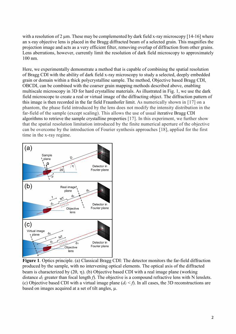
Here, we experimentally demonstrate a method that is capable of combining the spatial resolution
of Bragg CDI with the ability of dark field x-ray microscopy to study a selected, deeply embedded
grain or domain within a thick polycrystalline sample. The method, Objective based Bragg CDI,
OBCDI, can be combined with the coarser grain mapping methods described above, enabling
multiscale microscopy in 3D for hard crystalline materials. As illustrated in Fig. 1, we use the dark
field microscope to create a real or virtual image of the diffracting object. The diffraction pattern of
this image is then recorded in the far field Fraunhofer limit. As numerically shown in [17] on a
phantom, the phase field introduced by the lens does not modify the intensity distribution in the
far-field of the sample (except scaling). This allows the use of usual iterative Bragg CDI
algorithms to retrieve the sample crystalline properties [17]. In this experiment, we further show
that the spatial resolution limitation introduced by the finite numerical aperture of the objective
can be overcome by the introduction of Fourier synthesis approaches [18], applied for the first
time in the x-ray regime.
Figure 1. Optics principle. (a) Classical Bragg CDI: The detector monitors the far-field diffraction
produced by the sample, with no intervening optical elements. The optical axis of the diffracted
beam is characterized by (). (b) Objective based CDI with a real image plane (working
distance d1 greater than focal length f). The objective is a compound refractive lens with N lenslets.
(c) Objective based CDI with a virtual image plane (d1 < f). In all cases, the 3D reconstructions are
based on images acquired at a set of tilt angles, µ.

3
The demonstration experiment was carried out at beamline ID01 of the European Synchrotron
Radiation Facility, ESRF, using a compound refractive lens (CRL) [19] as objective. Selecting a Pt
grain with size ~500 nm within a thin Pt foil, rather than buried in a bulk polycrystal, allows a direct
comparison of our OBCDI method with classical Bragg CDI by translating the objective in and out
of the diffracted beam, respectively. The aim of this demonstration experiment is to detect and
characterize any deviations arising from introducing the objective. In all three configurations, the
full 3D intensity pattern is derived from a set of 2D patterns acquired during a “rocking-scan”,
where the sample is tilted at equidistant angular positions around the axis µ, perpendicular to the
incoming beam and the Bragg vector (see Fig. 1).
Figure 2. Reconstruction of a single Pt grain obtained without Fourier synthesis. Raw data taken
at the maximum of the rocking curve (first column), resulting 3D shapes of the selected grain
(second column) and phase reconstructions for the two blue planes indicated (third and fourth
column). The rows represent classical CDI (top), objective CDI with a virtual image plane
(middle) and objective CDI with a real image plane (bottom). The scale bars in (a-c) have the
same Fourier space length indicated in (c), a common scale bar for (d-f) is shown in (f) and a
common scale bar for (g-l) in (l). The images show the reconstructed complex fields, with the
phase represented by the color and the amplitude indicated by the intensity (hue), see the color
wheel inset in (l).
Corresponding raw data for the three configurations are shown in Fig. 2. They are similar in the
three configurations, with the exception of the anticipated cut-offs caused by the different numerical
apertures, cf. Table 1. The resulting reconstructions demonstrate good agreement between the no-
objective case and OBCDI. The spatial resolution (rms) is estimated from an error function fit of the
surface and is 6 nm, 18 nm and 60 nm, respectively, in the plane shown in Fig. 2g-i. In the
Supplementary Information (SI), we show that the differences can be explained almost solely by the
band pass defined by the aperture (Fig. S1). This is corroborated by the fact that there is no
noticeable difference along the third direction in reciprocal space, the rocking direction, where there

4
is no cut-off. Obtaining 18 nm resolution clearly shows that this method is not sensitive to the
CRL’s aberrations. This experimentally confirms the results in [17].
Figure 3. Reconstructions obtained using synthesis in Fourier space for OBCDI with a virtual
image plane. (a)-(c) Images at the center of the rocking curve (µ = 0°), (a) raw data from a single
dataset, (b) the reconstructed Fourier intensity using parallel synthesis, (c) the reconstructed
Fourier intensity using serial synthesis. The scale is logarithmic and covers 6 orders of
magnitude. (d-e) Reconstructions of two sections in the grain using parallel synthesis, (f-g)
reconstructions using serial synthesis, for direct comparison with results in Fig. 2. (a-c) has the
same scale, as do (d-g).
To increase the effective bandpass for the virtual image configuration (Fig. 1c), we repeated the
data acquisition over a 3x3 grid in the and directions (see Fig. 1 and Fig. S2 in SI). The grid
step size of 0.1° is 0.3 times the numerical aperture of the objective lens, corresponding to a 40-
70 % overlap of regions.
Two novel Fourier synthesis algorithms are introduced for the inversion of the nine 3D data sets.
In the first one, the data sets are treated in parallel. As an initial seed for all nine independent
reconstructions we use the object that was recovered using only the central position of the lens.
After convergence of the nine data sets, they are stitched in Fourier space by taking the mean of
the aligned reconstructions. The image registration is done using least squares optimization to
match the fringes in the intensity measurements, and the shifting is done by the Fourier shift
theorem, in order to perform the registration with sub-pixel accuracy. Alignment also involves
matching the global phase of the individual data sets, as they are phased separately. This
reconstruction method is robust, as it does not rely on any a priori information about the pupil
size or the exact position of objective. The final result exhibits an rms resolution of 13 nm, as
detailed in the SI. More importantly, as seen by comparing Figs. 3d-e with Figs. 2g and 2j, the
resulting phase reconstruction becomes remarkably similar to that of classical Bragg CDI.

5
The second scheme is based on updating sections of the global reconstructed Fourier plane with
the measurements in a serial fashion. This method requires knowledge of the pupil function, and
the image registration must be done before the reconstruction. The results are shown in Figs. 3f-
g, for direct comparison with Figs. 3d-e, 2g, and 2j. Here the resolution is improved to 11 nm
(see SI), but artifacts due to experimental instability are showing up, e.g. on the left edge in Fig.
3f. The serial synthesis has more difficulty converging, and is not stable enough to allow support
updating using the shrinkwrap algorithm, which we attribute to higher sensitivity to
inconsistencies between the nine data sets. In this case, we consider the parallel synthesis to
provide the better reconstruction, as the experimental drifts introduce too many artifacts in the
serial synthesis reconstruction. For both Fourier synthesis methods, we observe that overlap in
Fourier space is not necessary for a successful reconstruction.
In conclusion, we have demonstrated a new technique for 3D measurement of shape and strain
distribution of individual grains deeply embedded in a polycrystalline material. Compared to
state-of-the-art dark field x-ray microscopy, the spatial resolution can be improved by a factor of
at least 5 and is only limited by data acquisition time and experimental stability. Moreover, the
set-up presented is easily combined with both dark field x-ray microscopy and coarse grain
mapping of the entire specimen. The resulting ability to perform multiscale studies is vital for
investigating the dynamics of the microstructure in the vast class of structural materials, and as
such critical for the ambition of developing materials models of sufficient quality to enable
‘materials design in the computer’. This work is a proof-of-concept; the optimization of
experimental geometry and reconstruction algorithms as well as first applications on thick
specimens will be detailed in future publications. In particular, the recent manufacture of high
quality Multilayer Laue lenses [20] makes it possible to employ hard x-ray objectives with a
higher numerical aperture [21].
The approach presented shares its roots with e.g. Fourier Ptychography [22] and phase contrast
confocal microscopy [23]. It couples direct and Fourier space in several ways, with potential for
new applications, in microstructure imaging – which by definition is six-dimensional – and
elsewhere. The configuration with the real image plane enables images to be acquired in both direct
space and Fourier space (in the back focal plane or in the far field diffraction plane). This enables
combined reconstructions and the use of a priori knowledge about the sample, such as support
constraints, in both domains. We believe such advances could be a route towards higher resolution
in both domains and the possibility to extend CDI methods towards samples exhibiting more
complex strain variations.
Methods The sample is a Pt foil (99.95%, Alfa Aesar) cold rolled to 4 µm thickness. A 3x5 mm2 piece
was subsequently annealed at 650°C in air for 5 hours. Partial recrystallization took place,
resulting in ~500 nm sized grains with relatively low strain – ideal for Bragg CDI.
The experiment was carried out at beamline ID01 at ESRF at a photon energy of 8 keV. By a
combination of a Si(111) Bragg-Bragg monochromator, a slit and a KB mirror used as
condenser, a fully coherent incoming beam was generated with dimensions of 1.5 x 2.0 µm2 at
the sample position. The sample was mounted on a high precision Huber 3+2 circle
diffractometer with a hexapod and a piezo-stage for coarse and fine sample movements,
respectively. The removable CRL serving as objective comprised N identical Be biparaboloid
6
lenslets with an apex radius of curvature of 50 µm placed a distance T = 2 mm apart. N was 70
and 20 in the real and virtual image configuration, respectively. The microscope was aligned
with the optical axis corresponding to the Pt(111) Bragg peak, at 2θ ~ 40°. The far field detector
was a MaxiPix detector with 516x516 pixels of 55 µm size, mounted at the end of a detector
arm. An evacuated flight tube was placed between the CRL (or sample in the case of no
objective) and the detector to minimize air absorption and scattering.
In all cases we used a rocking step size of 0.003°. For the no objective and the virtual
image plane configurations we used 281 steps, for the real image plane configuration 101 steps.
Key geometrical parameters are summarized in Table 1. In all experiments, the sample-detector
distance was fixed at 1.632 m. Using geometrical optics expressions for a thick lens [15] the
distances were configured to match a magnification of 1.4 and -0.9, respectively. The actual
magnification was determined with high precision by comparing to the fringe pattern to the
Bragg CDI case.
N d1 d2 d3 M NA Deff σpupil NF
Bragg CDI - - - - - ~13.5 1.632 - -
OBCDI,
real image
70 0.121 0.100 1.271 -0.899 1.44 1.414 7.85 0.013
OBCDI,
virtual image
20 0.050 -0.119 1.661 1.409 5.5 1.179 25.2 0.032
Table 1. Key geometrical parameters. Distances are defined in Fig. 1 and are in meters. The
numerical aperture (NA) represents the FWHM of the detectors’ (for Bragg CDI) or CRL’s (for
OBCDI) angular acceptance and is in mrad. M is the magnification. Deff = d3/M is an effective
sample-detector distance, the distance at which the intensity patterns on a hypothetical detector
have the same scale as the Bragg CDI configuration. σpupil gives the rms width of the Gaussian
pupil function in units of pixels. NF is the Fresnel number at the entrance of the lens, assuming a
500 nm aperture (sample). This shows that the objective lens is placed in the far field limit.
The reconstructions without synthesis were performed by using a combination of the hybrid
input-output algorithm (HIO) [24] with a feedback parameter of β = 0.9, the error reduction
algorithm (ER) [25], and the shrinkwrap algorithm [26] to update the support. The initial guess
of the object was the inverse Fourier transform of the measured Fourier amplitudes with a
random phase, and the initial support was calculated from the autocorrelation function. 100
cycles of 20 x HIO + 1 x ER + shrinkwrap were repeated, followed by 100 cycles of 20 x HIO +
1 x ER, where the object was average after every cycle following [27].
For the parallel Fourier synthesis, we reconstructed the phase in the Fourier plane independently
for the eight additional datasets, and then synthesized the complex fields in the Fourier plane.
First, the image registration of the intensity patterns was determined by fitting the rocking curve
and employing a mean square difference optimization. The shifts within the images were
determined using the Fourier shift theorem, and were therefore determined to a sub-pixel
resolution. The intensity patterns were also normalized to match the Fourier amplitude between
each dataset. As an initial guess, the object reconstructed from the single data set at the center of
the grid was used, as well as the support. The ER algorithm was used to reconstruct the phase in
the Fourier plane, and after each step a combined object was formed by averaging the objects .
The shrinkwrap algorithm was used on this combined object. After 100 cycles the reconstruction
had converged, and the Fourier reconstructions were aligned and averaged. Alignment also

7
implied matching the global phase in the nine data sets, as these were phased individually, while
the phase retrieval algorithm only determines the relative phase within a data set. The final
object was found by inverting this synthesized Fourier amplitude and phase. In this experiment
we had slight sample drifts, impacting the position of the pupil function for each dataset, making
the alignment of the data set critically important.
The serial Fourier synthesis was carried out by updating the amplitude in Fourier space,
weighted by the Gaussian pupil function, with the measured intensities for one data set at a time.
The ER algorithm was used to enforce the support in between each updating cycle. Again, the
initial seed was the reconstruction from the central data set. At the end, the object was directly
recovered, in contrast to the parallel synthesis method.
Interestingly, we noticed that the convergence was still ensured if only a data subset extracted
from the nine data sets was used (e.g., four instead of nine). As one expect, it resulted however
in a slightly degraded solution due to the lower number of photons in the subsets. Those tests
demonstrated that the overlap in the Fourier domain does not bring additional information for the
phase retrieval. The inversion was made possible by the existence of a finite support in the real
space, making the link between our approach and CDI.
Acknowledgements
We acknowledge funding support from ERC Advanced Grant nr. 291321. We also acknowledge
funding from DanMAX, grant number 4059-00009B. We thank Yubin Zhang and Jacob Bowen
for help with providing the sample, Hugh Simons, Mario Beltran and Jens Wenzel Andreasen for
scientific discussions, ESRF for provision of beamtime (MI-1315) and the instrument center
Danscatt for a travel grant.
Author Contributions
AFP analyzed the data with input from VC. HFP conceived the original idea. AFP, VC and TZ
conceived and designed the experiment. TZ, AFP, CD, VC and GC performed the experiment.
HFP, AFP, VC and CD wrote the paper.
References
1. Sayre, D. Some implications of a theorem due to Shannon. Acta Crystallogr. 5, 843–843 (1952).
2. Miao, J., Charalambous, P., Kirz, J. & Sayre, D. Extending the methodology of X-ray
crystallography to allow imaging of micrometre-sized non-crystalline specimens. Nature 400, 342–
344 (1999).
3. Chapman, H. & Nugent, K. Coherent lensless X-ray imaging. Nature Phot. 4, 833–839 (2010).
4. Miao, J., Ishikawa, T., Robinson, I. K & Murnane, M.M. Beyond crystallography: Diffractive
imaging using coherent x-ray light sources. Science 348, 530–535 (2015).
5. Pfeifer, M.A., Williams, G.J., Vartanyants, I.A., Harder, R. & Robinson, I.K. Three-dimensional
mapping of a deformation field inside a nanocrystal. Nature 442, 63–66 (2006).|
6. Chamard, V., Stangl, J., Carbone, G., Diaz, A., Chen, G., Alfonso, C., Mocuta, C. & Metzger,
T.H. Three-dimensional x-ray Fourier transform holography: the Bragg case. Phys Rev Lett. 104,
165501 (2010).
7. Yau, A., Cha, W., Kanan, M.W., Stephenson, G.B. & Ulvestad, A. Bragg coherent diffractive
imaging of single-grain defect dynamics in polycrystalline films. Science 356, 739–742 (2017).

8
8. Chamard, V., Allain, M., Godard, P., Talneau, A., Patriarche, G. & Burghammer, M. Strain in a
silicon-on-insulator nanostructure revealed by 3D x-ray Bragg ptychography. Science Rep. 5,
(2015).
9. Mastropietro, F., Godard, P., Burghammer, M., Chevallard, C., Daillant, J., Duboisset, J., Allain,
M., Guenoun, P., Nouet, J. & Chamard, V. Revealing crystalline domains in a mollusc shell single-
crystalline prism. Nature Mater. 16, 946–952 (2017).
10. Poulsen, H.F. An introduction to three-dimensional X-ray diffraction microscopy. J. Appl.
Crystallogr. 45, 1084–1097 (2012).
11. Ludwig, W., Schmidt, S., Lauridsen, E. M. & Poulsen, H.F. X-ray diffraction contrast
tomography: a novel technique for three-dimensional grain mapping of polycrystals. I. Direct beam
case. J. Appl. Crystallogr. 41, 302–309 (2008).
12. King, A., Johnson, G., Engelberg, D., Ludwig, W. & Marrow, J. Observations of Intergranular
Stress Corrosion Cracking in a Grain-Mapped Polycrystal. Science 321, 382-385.
13. Lienert, U., Li, S.F., Hefferan, C.M., Lind, J., Suter, R.M., Bernier, J.V., Barton, N.R., Brandes,
M.C., Mills, M.C., Miller, M.P., Jakobsen, B. & Pantleon, W. High-energy diffraction microscopy
at the advanced photon source. JOM 63, 70–77 (2011).
14. H. Simons, A. King, W. Ludwig, C. Detlefs, W. Pantleon, S. Schmidt, F. Stöhr, I. Snigireva, A.
Snigirev & H. F. Poulsen. Dark-field X-ray microscopy for multiscale structural characterization.
Nature Commun. 6, 6098 (2015).
15. Poulsen, H.F., Jakobsen, A.C., Simons, H., Ahl, S.R., Cook, P.K. & Detlefs, C. X-ray
diffraction microscopy based on refractive optics. J. Appl. Crystallogr. 50, 1441–1456 (2017).
16. Simons, H., Haugen, A.B., Jakobsen, A.C., Schmidt, S., Stöhr, F. Majkut, M., Detlefs, C.,
Daniels, J.E., Damjanovic, D. & Poulsen, H.F. Long-range symmetry breaking in embedded
ferroelectrics. Nature Mater. (2018) Available on-line.
17. Pedersen, A.F., Chamard, V. & Poulsen, H.F. A numerical study of Bragg CDI on thick
polycrystalline specimens. Optical Express. In print (2018).
18. Alexandrov, S. A., Hillman, T. R., Gutzler, T. & Sampson, D. D. Synthetic Aperture Fourier
Holographic Optical Microscopy. Phys. Rev. Lett. 97, 168102 (2006).
19. Snigirev, A., Kohn, V., Snigireva, I. & Lengeler, B. A compound refractive lens for focusing
high-energy X-rays. Nature 384, 49-51 (1996).
20. A. J. Morgan, M. Prasciolu, A. Andrejczuk, J. Krzywinski, A. Meents, D. Pennicard, H.
Graafsma, A. Barty, R. J. Bean, M. Barthelmess, D. Oberthuer, O. Yefanov, A. Aquila, H. N.
Chapman, and S. Bajt, High numerical aperture multilayer Laue lenses, Sci. Rep. 5, (2015).
21. Murray, K.T., Pedersen, A.F., Mohacsi, I., Detlefs, C., Morgan, A.J., Prasciolu, M., Yildirim,
C., Simons, H., Jakobsen, A.C., Chapman, H.N., Poulsen, H.F. & Bajt, S. Multilayer Laue lenses at
high x-ray energies: Performance and applications. Submitted (2018).
22. G. Zheng, R. Horstmeyer and C. Yang. Wide-field, high-resolution Fourier ptychographic
microscopy. Nat Photonics. 7, 739–745 (2013).
23. Liu C, Marchesini S, Kim MK. Quantitative phase-contrast confocal microscope. Opt Express
22, 17830-9 (2014).
24. Fienup, J.R. Phase retrieval algorithms: a comparison. Appl. Opt. 21, 2758 (1982).

9
25. Cha,W., Song, S., Jeong, N.C., Harder, R. Yoon, K.B., Robinson, I.K. & Kim, H. Exploration
of crystal strains using coherent x-ray diffraction. New J. Phys. 12, 035022 (2010).
26. S. Marchesini, H. He, H. N. Chapman, S. P. Hau-Riege, A. Noy, M. R. Howells, U. Weierstall
& J. C. H. Spence. X-ray image reconstruction from a diffraction pattern alone. Phys. Rev. B 68,
140101 (2003).
27. Shapiro, D. Thibault, P., Beetz, T., Elser, V., Howells, M., Jacobsen, C., Kirz, J., Lima, E.,
Miao, H., Neiman, A.M. & Sayre, D. Biological imaging by soft x-ray diffraction microscopy.
Proc. Natl. Acad. Sci. 102, 15343–15346 (2005).

Supporting information: X-ray coherent diffraction imaging with an
objective lens: towards 3D mapping of thick polycrystals Anders Filsøe Pedersen1, Virginie Chamard2, Carsten Detlefs3, Tao Zhou3, Dina Carbone4, Henning
Friis Poulsen1*
1: Department of Physics, Technical University of Denmark, 2800 Kongens Lyngby, Denmark
2: Aix Marseille Univ, CNRS, Centrale Marseille, Institut Fresnel, Marseille, France
3: European Synchrotron Radiation Facility, 71 Avenue des Martyrs, 38000 Grenoble, France
4: MAX IV Laboratory, Fotongatan 2, 225 92 Lund, Sweden
*: corresponding author, [email protected]
Simulation of the effect of the aperture We can simulate the effect of the pupil function on the classical (lensless) Bragg CDI data. To this end
we Fourier transform the reconstruction for the classical BCDI – shown in Fig. S1a – multiply by the
Gaussian pupil function with the width specified in Table 1 in the main text, and then inverse Fourier
transform the result back to real space. The results using the pupil functions for the virtual and real
image geometry are displayed in Figs. S1b-c, respectively. These results can be compared directly to
the reconstructions with the objective in place, shown in Figs. 2h-i, and for convenience reproduced
here as Figs. S1d-e. It is evident that the discrepancy between the classical BCDI result and the
OBCDI results to a large extent can be explained by the finite pupil.
Figure S1. A study of the effect of the finite pupil on reconstruction quality. The classical BCDI
reconstruction in (a) is used as a phantom for numerical studies. Results from applying a pupil of
size corresponding to the virtual image case (b), and the real image case (c) are compared to the
reconstructions from the measurements with the lens in the virtual and real image geometry in
(d) and (e), respectively. All plots share the same scale.

Measurements for Fourier synthesis
Figure S2. The intensity pattern recorded at the central Bragg peak for the nine data sets used for
Fourier synthesis. The images are plotted on a logarithmic scale covering six orders of magnitude.
The rows correspond to steps in 2θ and the columns to steps in η angle. The scale of all the images is
the same with a common scale bar shown in (i).
Shown in Fig. S2 are corresponding examples of raw data for the nine data sets used for the Fourier
synthesis in the virtual image geometry. The step size in 2θ and η are both 0.1° steps. The white lines
are gaps between the detector modules.

Fourier synthesis resolution The resolution of the two Fourier synthesis methods is evaluated by comparing the extent of the
intensity in Fourier space. Fig. S3 shows the normalized mean intensity as a function of reciprocal
space length in the detector plane. Compared to the reconstruction based on a single data set only,
the extent of the Fourier intensity at a relative level of 10-3 is increased by 36% and 64% for the
parallel and serial Fourier synthesis, respectively. This translates into improving the resolution from
18 nm to 18/1.36 = 13 nm and 18/1.64 = 11 nm, respectively.
Figure S3. The averaged and normalized intensity for the single data set and the two Fourier
synthesis methods are plotted against the q-vector magnitude in the detector plane.


