
0 OF 95 PDATA-1342 REV. 1
Document Title: WO 8387 INSTALLATION, OPERATIONS AND MAINTENANCE MANUAL –
LINEAR CHAIN JACK MOORING SYSTEM
Document Number: PDATA-1342
Revision: Prepared By: Checked By: Approved By: Date:
1 W. Pattee N. Atallah T. Miller 2/09/07
CONFIDENTIAL This document contains confidential and proprietary information and may not be released in whole or in part without the expressed written permission of Bardex Corporation.

1 OF 95 PDATA-1342 REV. 1
W.O. 8387
LINEAR CHAIN JACK MOORING SYSTEM
INSTALLATION, OPERATIONS AND MAINTENANCE MANUAL
FOR THE JACK BATES MOORING SYSTEM UPGRADE
PREPARED FOR TRANSOCEAN OFFSHORE DEEPWATER DRILLING, INC.
P.O. NO. P973587
BARDEX CORPORATION 6300 LINDMAR DRIVE
GOLETA, CA 93117 U.S.A.
09 FEBRUARY, 2007
TELEPHONE: +1(805) 964-7747 FAX: +1(805) 683-1763 E-MAIL: [email protected] www.BARDEX.com

2 OF 95 PDATA-1342 REV. 1
NOTE 1 This manual contains proprietary information and designs owned by Bardex Corporation. All designs, manufacturing, reproduction, use, patent rights, and sales rights regarding the same are expressly reserved by Bardex Corporation.
NOTE 2 FAILURE TO INSTALL, OPERATE, OR MAINTAIN THE SYSTEM IN ACCORDANCE WITH THIS TECHNICAL MANUAL MAY INVALIDATE THE WARRANTY.
NOTE 3 FOLLOW ALL ESTABLISHED SAFETY PRECAUTIONS AND REGULATIONS AT ALL TIMES.
NOTE 4 The system shall be operated and maintained by trained personnel only. Bardex Corporation may be contacted with questions, requests for information, or for spare or replacement part orders at: Bardex Corporation 6300 Lindmar Drive Goleta, CA 93117, U.S.A. Attention: Support Services Telephone: +1 805 964-7747 Facsimile: +1 805 683-1763 E-mail: [email protected] Website: www.bardex.com

3 OF 95 PDATA-1342 REV. 1
TABLE OF CONTENTS
SECTION DESCRIPTION
1.0 INTRODUCTION ........................................................................................... 5 2.0 INSTALLATION ........................................................................................... 11 3.0 COMMISSIONING ...................................................................................... 22 4.0 EQUIPMENT SPECIFICATIONS ................................................................ 39
5.0 OPERATION ............................................................................................... 41 6.0 MAINTENANCE .......................................................................................... 54
7.0 SPARE PARTS ........................................................................................... 85
8.0 TROUBLE SHOOTING ............................................................................... 85
9.0 ENGINEERING DRAWINGS ...................................................................... 93

4 OF 95 PDATA-1342 REV. 1
TABLE OF BARDEX TECHNICAL DOCUMENTS SUPPLIED IN THE APPENDIX
TS-1007 Technical Specification for Tightening Bolts and Fittings
TB-2010 Technical Bulletin for Preservation and Storage of Bardex Hydraulic Equipment
TB-2012 Technical Bulletin for Instructions for Unpacking, Inspection, and Storage of Bardex Equipment
TB-2013 Technical Bulletin for Instructions for Lifting and Transportation of Bardex Equipment
TB-2014 Procedure for Hydraulic Pipe System Cleaning, Pickling and Preserving
TB-2018 Hydraulic Fluid Selection and Fluid Maintenance for Bardex Hydraulic Systems
TB-2019 Electric Motor Lubrication
TB-2020 Long Term Storage of Chain Jacks
TB-2021 Installation Instructions for Swagelok Tube Fittings
TB-2023 Handling, Storage & Maintenance of Spare Parts
TB-2030 Operation and Maintenance for Combination Chain/Wire Sheave
PS-1008 Process Specification for Cleaning and Flushing of Equipment Piping Systems

5 OF 95 PDATA-1342 REV. 1
1.0 INTRODUCTION
This manual contains installation, operations, and maintenance information for
the Bardex Linear Chain Jack Mooring System Upgrade to be used on the Jack
Bates Vessel. Proper operation and maintenance procedures are essential to the
continued safe and reliable performance of the equipment. It is extremely
important that all supervisors and operators are properly trained and familiar with
the procedures and instructions contained in this manual. If questions arise
regarding any aspect of this document or the equipment, contact Bardex
Corporation.
1.1 SYSTEM DESCRIPTION
The vessel is installed in the Gulf of Mexico and will have additional
mooring system capacity by means of four (4) taut leg anchor lines. The
anchor lines are pulled in, tensioned, and held by the Bardex Chain Jack
Mooring System consisting of four (4) Linear Chain Jack and Turndown
Sheave sets with associated Control Consoles and Hydraulic Power Units.
Each Control Console station allows manual operation of the Chain Jack
hydraulics and provides the operator with both hydraulic pressure
monitoring and chain tension readout. Each Chain Jack is powered by a
dedicated Hydraulic Power Unit.
Mooring Chain Size: 3-9/16 inch RQ3S Stud link Anchor Chain with a
breaking strength of 1685 kips

6 OF 95 PDATA-1342 REV. 1
The mooring chain travels through the lower hull fairlead (provided by
others) then up along the hull to the Chain Jack Assembly and associated
mooring line equipment. Each mooring station consists of one Bardex
Linear Chain Jack, with integral chain stopper, and one Chain Turndown
Sheave. The chain passes through the Chain Jack and over the
Turndown Sheave into the chain hawse pipe. Each Chain Jack Assembly
provides the force required to “HAUL IN” or “PAY OUT” the mooring chain.
The integral chain stopper mechanically holds the chain during idle
periods of operation. When moored, the chain rests on the stopper
assembly.
The chain jacks are arranged in four (4) groups with each group
containing one (1) Chain Jack. The entire system consists of the following
equipment and components:
1.2 SCOPE OF SUPPLY
ITEM QTY DESCRIPTION
1.
4
Linear Chain Jack Assemblies - 550 kips stall capacity /600 kips
mechanical hold capacity on the Traveling Latch Assembly,
Integral 1685 kip capacity Chain Stopper, Two Lift Cylinders,
and one shared Load Holding Valve Assembly.
2.
4
Control Console Assemblies – Control Valve Manifold Assembly
with Manual Capability, Load Indicating Pressure Gauge for
Load Monitoring when chain is being held by lift cylinders;
Redundant electrical Instrumentation for Load Monitoring (with
digital serial link output) when chain is resting on the fixed
stopper.

7 OF 95 PDATA-1342 REV. 1
ITEM QTY DESCRIPTION
3.
4
Turndown Sheave Assemblies - Complete with Chain Wheels
sized for 3-9/16 inch diameter Mooring Chain, Deck Mounting
Structure, Temporary Sheave Anti-rotation Pins and one set of
removable inserts for 1-1/2 inch maximum messenger wire rope.
4.
4
Hydraulic Power Unit Assembly - Complete with Dual 60 HP
TEFC Electric Motors and dual 18 GPM Variable Displacement
Piston Pumps (total 36 GPM), 7.5 HP TEFC Electric Motor for
heat exchanger fan, HPU Electrical Control Enclosure,
Interconnecting Supply & Return Interface for Chain
Jack/Control Console
1.3 LINEAR CHAIN JACK ASSEMBLY
Refer to drawings DWG-102118-Chain Jack Assemlby-3-9/16”, DWG-
102122-Fixed Crossarm Assembly & DWG-102140-Traveling Crossarm
Assembly
The major components of the Linear Chain Jack Assembly are: two (2)
double acting hydraulic tension cylinders, a traveling lower crossarm with
synchronous acting latch system and a fixed upper crossarm with integral,
synchronous chain stopper latches.

8 OF 95 PDATA-1342 REV. 1
Each Bardex Chain Jack can “HAUL IN” or “PAY OUT” the mooring chain
in a series of coordinated operations of latching, jacking, and unlatching.
The latches do not rely on friction to hold the load. Latching devices
contact the bottom surface of the chain link to support the load by cradling
it in a pocket on both sides of the latch or stopper.
The Chain Stopper (fixed latches) is located on the fixed upper crossarm
and holds the chain between power strokes. The traveling latches are
located on the lower crossarm which is attached to the lift cylinder rod
ends.
Both latch sets are hydraulically actuated and are mechanically
interlocked. Transfer of the load onto the latches is made only after the
latches are engaged. Once the latches are loaded there is not sufficient
hydraulic pressure available to inadvertently disengage them. Each latch
mechanism is designed to be self-locking during normal operation. This
prevents inadvertent latch disengagement resulting from hydraulic failure
or operator error.
Latches are manufactured from high strength alloy steel having a surface
hardness that is less than the chain surface hardness. The Chain Jack is
designed to jack on and pass the 3-9/16 inch Mooring Chain and
appropriate sized Kenter and Pear links.
The chain links may be fed into the chain jack crossarm(s) in either
orientation during installation.
9 OF 95 PDATA-1342 REV. 1
1.4 TURNDOWN SHEAVE
Refer to DWG-102106-Chain Sheave Assembly
After the chain is pulled in by the chain jack, it passes over a turndown
sheave and into a chain hawse pipe. The turndown sheave is designed to
allow the common studlink and Kenter and Pear connecting links to pass
over it in either orientation.
1.5 CONTROL CONSOLE
Refer to DWG-102181-Control Console Assembly
The Control Console assembly includes manually operated hydraulic
control valves, a load indicating pressure gauge and an electrical
enclosure with instrumentation for load monitoring.
1.6 HYDRAULIC POWER UNIT ASSEMBLY
Refer to DWG-102194-Hydraulic Power Unit Assembly
The hydraulic system has been designed with one dedicated hydraulic
power unit operating each Chain Jack at approximately 3.1 ft/min haul in
or 2.5 ft/min pay out for a load of up to 275 kips. This speed is based on
use of a dual motor/pump arrangement; half speed is obtained if one
motor/pump is not running. Load capacity is unaffected by the number of
pumps running.

10 OF 95 PDATA-1342 REV. 1
Component arrangement has been kept as simple as possible to minimize
the total number of components and to assure maximum reliability.
Pumps and valves are mounted outside the tank (reservoir) for easy
access in the event of the need for service or maintenance.
The reservoir is fabricated from painted stainless steel and contains
internal baffles to facilitate heat dissipation and prevent oil starvation at
pump inlet due to vessel motion. The reservoir is mounted above the
pump(s) to maximize pump suction head extending pump life. Access to
the reservoir interior for cleaning is from the side through a removable
cover.
1.7 MOORING CONTROL SYSTEM SUMMARY
Bardex’s Mooring Control System conforms to all requirements for reliable
performance and operation in the offshore marine environment.
Each Chain Jack Assembly must be manually operated from the hydraulic
control console panel. The operator shifts levers to actuate each step of
the jacking sequence.
Refer to the Operations Section of this manual for a detailed description of
the jacking sequence.
Redundant compression load cells are provided in the Chain Jack fixed
crossarm plate under opposing stopper latches. The load cells are
connected to the control console digital display to indicate the average
chain tension in kips. The reading is only accurate when the chain is
resting on the fixed stopper latches.

11 OF 95 PDATA-1342 REV. 1
2.0 INSTALLATION
The following section outlines the recommended steps to be performed to
properly install the equipment on the vessel.
2.1 HYDRAULIC POWER UNIT (HPU)
2.1.1 Disassembly of Shipping Crate
The HPU shipping arrangement was configured for fork lifting only.
Removal of the top wooden sheets will allow access to the four lift
eyes located within the frame corners, as required for crane lifting.
1. Prior to removing the wooden skid base steel bands, position
the HPU in a location that can be accessed by a crane with
the required lift capacity.
2. Remove the steel bands to separate the skid from the HPU
frame. Leave all other packing in place to protect gauges
and panels during installation.
3. Connect a lift sling to each of the four lift points located on
the frame. The sling length should be selected so that the
sling angle does not exceed 30 degrees from the vertical
axis.
4. Refer to TB-2013 “Instructions for Lifting and Transportation
of Bardex Equipment”

12 OF 95 PDATA-1342 REV. 1
2.1.2 Hydraulic Power Unit Flushing for Pre-commissioning
During the pre-commissioning phase, verify that all hoses to be
connected to the HPU have been cleaned and flushed per Bardex
PS-1008.
CAUTION: FAILURE TO PROPERLY FLUSH THE SYSTEM
PRIOR TO INTERCONNECTION MAY RESULT IN COMPONENT
MALFUNCTION.

13 OF 95 PDATA-1342 REV. 1
2.1.3 Hydraulic Fluid Selection
Bardex has approved the use of Chevron Clarity ISO AW 46
mineral based hydraulic fluid for use in this system. All hydraulic
components were factory tested using this fluid and will contain
some residual oil. If another fluid is selected, the user must verify
compatibility with Chevron Clarity prior to use. Refer to TB-2018,
Hydraulic Fluid and Maintenance Guidelines, for important
information regarding hydraulic fluid selection. In the event that the
fluid selected is an Environmentally Evaluated fluid, note that strict
guidelines may be required for the production, installation, and
maintenance of this different fluid type. These guidelines are not
within the scope of this manual and must be obtained from the fluid
supplier.
IMPORTANT: BARDEX SHOULD BE CONTACTED PRIOR TO
USE OF ANY ENVIRONMENTALLY EVALUATED VEGETABLE
BASE FLUID OR ENVIRONMENTALLY ACCEPTED (EA)
SYNTHETIC ESTER FLUID IN THIS SYSTEM.
All Chain Jack Assemblies, latch cylinders, and HPU pump cases
were drained prior to shipping; however, some residual mineral
based ISO AW 46 grade hydraulic fluid may remain. If this fluid is
not compatible with the chosen fluid for the system, it must be
drained and disposed of properly. Refer to Section 3.2 for
procedures on draining the hydraulic fluid from system components
if Chevron Clarity AW 46 is not used.

14 OF 95 PDATA-1342 REV. 1
CAUTION: SPECIAL COLD WEATHER STARTING PRE-
CAUTIONS ARE NECESSARY WHEN THE AMBIENT
TEMPERATURE IS LESS THAN 5º CELSIUS (41º
FAHRENHEIT). REFER TO TB-2018 IN THE APPENDIX.
After draining hydraulic fluid, fill with the proper fluid prior to
operation in accordance with Section 3.2.
2.1.4 HPU Electrical Installation
Refer to Hydraulic Power Unit Assembly, DWG-102194, and
Electrical Schematic, DWG-102180, for proper connection of cables
and wiring to the HPU electrical enclosure.
CAUTION: CORRECT MOTOR ROTATION MUST BE
CONFIRMED PRIOR TO INITIAL START-UP OF THE HPU. BE
SURE INLET SUCTION VALVES ARE OPEN AND THE
HYDRAULIC PUMPS ARE PRIMED FOR START-UP PRIOR TO
“JOG STARTING” OR “JOGGING” THE MOTORS TO CHECK
ROTATION. PROPER ROTATION IS INDICATED VIA AN
ARROW ON THE PUMP HOUSING.
2.2 CHAIN JACK AND CONTROL CONSOLE ASSEMBLY INSTALLATION
Refer to drawing DWG-102159-Mooring System Interface-3-9/16”
Each Chain Jack Assembly and Turndown Sheave is installed on a Chain
Jack Foundation plate, which is structurally integral to the hull. Refer to
the Mooring System Interface Drawing, DWG-102159 to obtain the
foundation geometry and loading requirements.

15 OF 95 PDATA-1342 REV. 1
2.2.1 Preparation for Chain Jack Installation
1. Remove the steel bands and the bolts to the wooden support
beam attaching the chain jack to the shipping skid.
2. Protect the exposed lift cylinder rod surface from mechanical
damage during handling by wrapping with heavy rubber or
other suitable material. A split piece of large diameter low
pressure hydraulic hose secured with duct tape or tie wraps
is suggested. Note: the chain jacks were shipped with the
cylinders fully retracted.
2.2.2 Chain Jack Installation
1. The hull foundation plate must be flat under the Chain Jack.
If it is not, a chocking compound may be used to ensure that
the Chain Jack is evenly supported. All mounting holes
should be pre-drilled. The hull foundation mounting surface
must be checked for proper interface using the Bardex
supplied interface template (Part number DWG-102208-4)
prior to installing the Chain Jack and/or Turndown Sheave.
2. Lift the Chain Jack off of the shipping base using the
appropriate lifting eyes. Refer to TB-2013 as required.

16 OF 95 PDATA-1342 REV. 1
CAUTION: THE CYLINDER RODS MAY EXTEND DUE TO
GRAVITY IF THE CHAIN JACK BECOMES PARTIALLY
VERTICAL WITH THE ROD END DOWN. BE SURE SUFFICIENT
RESTRAINT IS IN PLACE ACROSS THE TWO CROSSARMS TO
PREVENT INADVERTENT EXTENSION OF THE LIFT CYLINDER
RODS. RESTRAINTS SHOULD BE LOCATED NEAR THE RODS
OR ON THE OUTBOARD EDGE OF THE CHAIN JACK TO
PREVENT INTERFERENCE WITH THE FOUNDATION
STRUCTURE.
CAUTION: ALWAYS USE AT LEAST TWO EYES FOR LIFTING.
3. The Chain Jack is designed to be installed as one unit.
However, if the lower crossarm must be removed for
installation, the Chain Jack must be in the vertical position
prior to removal (disassembly). Refer to Section 6.2.1.
4. Position the Chain Jack near the foundation as shown on the
Mooring System DWG-102158. Insure the bearing pads,
item 16 on the Traveling Crossarm Assembly (DWG-
102140) enter the guide tracks. Lower the Chain Jack until
the contact surfaces on the underside of the Fixed Crossarm
are flush with the foundation base.
5. Lubricate then install the Chain Jack Assembly mounting
bolts (by others) and hand tighten.
6. Torque the bolts to 25% of the recommended value as
specified on DWG-102158.

17 OF 95 PDATA-1342 REV. 1
NOTE: BARDEX RECOMMENDS THAT ALL MOUNTING
HARDWARE BE COATED WITH A RUST PREVENTATIVE
LUBRICANT OR AN APPROPRIATE THREAD
SEALER/LOCKER SUCH AS LOCTITE # 242 OR EQUIVALENT.
7. Re-install the traveling crossarm to the Chain Jack (if
disassembled). See Section 6.2.1 if necessary.
8. With the Chain Jack traveling cross arm completely retracted
the following fit and alignment checks should be performed:
A. Fixed cross arm support contact surface is flat and
fully supported on the foundation structure.
B. Side load bearing pads should be centered in the
guide tracks.
C. Chain cutout on the Chain Jack fixed cross arm is
clear of the support structure below.
D. Chain Jack centerline should be in line with the chain
hawse pipe and fairlead below
E. Tighten all mounting hardware. Torque mounting bolts
per DWG-102158 with Loctite 242 (or equivalent)
applied to the bolt threads.
18 OF 95 PDATA-1342 REV. 1
F. Ensure there are no interferences when the Chain
Jack Traveling Crossarm is lowered (cylinders
extended).
If the system hydraulic fluid is not compatible with Chevron Clarity
petroleum based AW 46 grade fluid, refer to Section 3.2
Commissioning, to remove the existing residual hydraulic fluid left
in the System from Factory Testing.
2.2.3 Control Console Mounting and Interconnection to Chain Jack
and Hydraulic Power Unit.
Refer to Mooring System 3-9/16” DWG-102158, and Hydraulic
Schematic DWG-102186.
Locate the Control Console near the Chain Jack to enable the
operator full view of the Chain Jack fixed stopper and traveling
latches. Secure the console to the deck via bolting or welding.
Route hydraulic piping/hose connections to and from the HPU and
Chain Jack Manifold. Ensure that all piping/hose runs have been
flushed. Double check that all connections have been made per the
hydraulic schematic and that they are tight. Figure 1 shows
labeling for the Control Console Interfaces, less the large HPU
supply and return 4-bolt flange connections. These are located on
the opposite side of the console (right hand side as viewed from the
operator’s position).

19 OF 95 PDATA-1342 REV. 1
Figure 1
Close up of Control Console Hydraulic Interface
2.2.4 Chain Jack Load Monitoring
Route the Load Cell cables (2 each) from the Chain Jack fixed
cross arm to the Control Console Electrical Enclosure. Secure the
cables with clamps or wire ties as required to keep these out of
high traffic areas.

20 OF 95 PDATA-1342 REV. 1
Holes must be drilled in the bottom of the enclosure for the selected
gland size(s) for the load cell cables (2X .88 inch diameter cable),
input power and load cell serial communication uplink (by others).
Use caution in drilling the holes for these glands such that interior
components are not damaged. The enclosure door can be opened
to assess available space. Be sure and close the door when
finished to keep the electronics dry. A desiccant is supplied inside
each enclosure and should be replaced on a yearly basis or sooner
if any signs of moisture intrusion are seen.
Refer to the Electrical Schematic-Mooring System DWG-102180 for
wiring diagram and details.
2.3 Turndown Chain Sheave Installation
Refer to DWG-102159 (Mooring System Interface), DWG-102158
(Mooring System, 3-9/16”) and DWG-102106 (Chain Sheave Assembly).
NOTE: VERIFY PROPER FOUNDATION INTERFACE USING THE
FOUNDATION TEMPLATE (DWG-102208-4) PRIOR TO TURNDOWN
SHEAVE INSTALLATION.
1. Make sure the foundation is prepared to receive the Chain Sheave
Assembly. See DWG-102159 for interface information.
2. Disassemble the shipping skid and remove the steel bands and
protective covers.
3. Lift the Chain Sheave Assembly using the lifting eyes located on
the frame.

21 OF 95 PDATA-1342 REV. 1
CAUTION: ALWAYS USE AT LEAST TWO EYES FOR LIFTING.
4. Position the Chain Sheave Assembly over the foundation, then
using the mounting bolt holes, align it onto the foundation. Install
fasteners as detailed on DWG-102158.
5. Tighten the fasteners until the Sheave base is flush with the
foundation. Torque the bolts per DWG-102158 when lubricated
with Loctite 242 (or equivalent).
22 OF 95 PDATA-1342 REV. 1
3.0 COMMISSIONING
3.1 Equipment Inspection and Setup
This section defines the steps to be performed after initial installation.
This section presumes that no physical damage has occurred during
transportation.
3.1.1 Mechanical Equipment
1. Visually inspect all Chain Jacks for mechanical damage or
the presence of debris. Replace or repair any components
that are damaged.
2. Check the hydraulic circuit for external damage. Hydraulic
hoses should be replaced if the wire braids are visible.
3. Remove all temporary supports used for transport or sea
fastening of the Chain Jacks and/or Control Consoles
including any mechanical covers and hose tie down straps
that may have been installed for transportation.
4. Verify that all fasteners remain intact and are in good
condition. Re-torque any fastener that may have loosened
during transport per DWG-102158.
5. Ensure that all rig piping/tubing has been flushed and
pressure tested.

23 OF 95 PDATA-1342 REV. 1
6. Ensure that all interconnecting hydraulic fittings and flange
bolts are properly tightened.
3.2 Hydraulic Fluid Filling and Draining / Air Purging
Refer to drawings DWG-102194 (HPU), DWG-102181 (Control
Console Assembly) and DWG-102188 (Chain Jack Piping &
Electrical).
3.2.1 Draining the System
NOTE: THIS STEP IS NOT REQUIRED DURING INITIAL START-
UP UNLESS TANK BECOMES CONTAMINATED DURING
TRANSPORT OR A FLUID IS BEING USED THAT IS
INCOMPATIBLE WITH THE FLUID USED IN THE FACTORY
TESTING. REFER TO SECTION 2.1.3 IF A DIFFERENT
HYDRAULIC FLUID IS PROPOSED.
The following procedure defines the steps necessary to drain the
system of fluid for replacement. It presumes that the complete
system, including piping, has been filled and that the vessel is in its
normal (floating) orientation.
NOTE: ALWAYS TAKE PRECAUTIONS TO CAPTURE AS MUCH
FLUID AS POSSIBLE TO MINIMIZE ENVIRONMENTAL CON-
TAMINATION. NEVER RE-USE DRAINED, USED, OR
UNKNOWN FLUID IN THE HYDRAULIC SYSTEM.
1. Drain the fluid in the reservoir using the drain fitting provided.

24 OF 95 PDATA-1342 REV. 1
2. Remove the reservoir cover and use a scraper attached to a
rod to scrape oil in the bottom of the reservoir over to the
drain hole. Replace cover when finished.
CAUTION: BE CAREFUL NOT TO INTRODUCE
CONTAMINANTS INTO THE RESERVOIR WHEN REMOVING
FLUID.
3. Remove and replace the return and pressure filter elements.
4. At the HPU, disconnect the pump hoses at the lower end in
order to drain. Drain the fluid from the pump by removing
the lowest drain plug from the case. Be sure that the suction
line ball valves are open. Select a fitting that is as low as
possible to maximize the amount of fluid which is drained.
5. Try to locate areas in the equipment and piping where fluid
may be trapped (i.e., a low point in the piping). These low
areas may need to be separately drained. Use dry and
filtered compressed air, with maximum pressure of 150 psi, if
necessary to force oil down the tubing to remove as much oil
as possible.
6. Reconnect all hoses and fittings at the HPU.

25 OF 95 PDATA-1342 REV. 1
7. Drain all fluid from the interconnecting piping/hoses between
the power unit and the chain jack by connecting compressed
air to one end (dry and filtered) while holding the other end
into a suitable container to catch the escaping fluid. An
alternate method for hoses is to use gravity by hanging one
end into a suitable container from a sufficient height and
crack open the fitting until the fluid escapes. Note that the
high end must be open to drain the hose properly.
8. Disconnect the supply tubing to the cylinder blind end at the
Manifold Assembly on the chain jack (open the extend port
fitting). Catch the fluid as it escapes from the manifold
extend fitting in the drip pan provided. Drain the drip pan as
necessary during the draining sequence.
NOTE: THERE ARE APPROXIMATELY 20 GALLONS OF FLUID
IN THE LIFT CYLINDERS (10 GALLONS EACH). THE FLUID
SHOULD BE DRAINED INTO A SUITABLE CONTAINER.
CAUTION SHOULD BE OBSERVED WHEN DRAINING
CYLINDERS. BEGIN BY CRACKING THE FITTING(S) AND
LETTING THE FLUID DRAIN SLOWLY.
NOTE: IF THE TRAVELING CROSS ARM IS NOT PHYSICALL
RESTRAINED IT WILL EXTEND AS FLUID IS DRAINED. DO NOT
OPEN FITTINGS ALL THE WAY OR FLUID WILL BE EXPELLED
IN AN UNCONTROLLED MANNER.

26 OF 95 PDATA-1342 REV. 1
9. Drain fluid from the Chain Jack lift cylinders at each Chain
Jack by disconnecting the load indicating gauge tube fitting
at the Chain Jack and/or per the next step.
10. Disconnect the Extend and Retract connections to the
Control Console Assembly at the Interface Panel. Catch the
fluid as it escapes from the tubing in the drip pan provided.
Drain the drip pan.
11. Disconnect the fixed latch cylinder from the assembly with
the hoses still connected. Lower the cylinder assembly to a
position as low as possible. Disconnect the hose
connections at the cylinder and allow it to drain into a
suitable container.
12. Disconnect the traveling latch cylinder from the assembly
with the hoses still connected. Lower the cylinder assembly
to a position as low as possible. Disconnect the hose
connections at the cylinder and allow it to drain into a
suitable container.
13. Extend and retract latch cylinders by hand to push any fluid
out that may remain inside.
14. Reconnect all hoses and fittings and reassemble to insure
no contaminants are introduced or damage is incurred.
3.2.2 Filling the System
27 OF 95 PDATA-1342 REV. 1
CAUTION: ALWAYS FILL THE SYSTEM WITH CLEAN PRE-FILTERED
OIL THAT MEETS ISO 18/16/13 (NAS CLASS 7) FLUID CLEANLINESS
REQUIREMENTS. REFER TO PS-1008 AND TB-2018 IN THE
APPENDIX FOR MORE INFORMATION. WHEN FILLING THE SYSTEM
ALWAYS FILTER THE NEW OIL THROUGH A 3 TO 5 MICRON FILTER
AS IT IS ADDED TO THE RESERVOIR. NOTE THAT NEW OIL
USUALLY DOES NOT MEET CLEANLINESS REQUIREMENTS.
1. Verify that all ports are connected and the Reservoir drain
valve is closed. (Ref: DWG-102194)
2. Fill the reservoir with oil using a fill system which has an
inline 5 micron absolute filter. The reservoir is filled using a
hose connected to the tank breather port on top of the
reservoir or the return port (Refer to DWG-102194). Filling
the tank through the return line port routes the new oil
through the return filter. The quantity of oil required for the
system is approximately:
NOTE: ENSURE THAT HPU RETURN LINE IS CONNECTED TO THE
CONTROL CONSOLE AND FITTINGS ARE TIGHTENED AS IT WILL
FILL UP AT THE SAME TIME THE RESERVOIR DOES.

28 OF 95 PDATA-1342 REV. 1
ITEM QUANTITY (GALLONS)
Reservoir 120
Chain Jack (with cylinders retracted)
20
Misc. 5
TOTAL 145
3. Fill the HPU pump cases with the new system fluid by
removing the pump case fill plugs and filling with clean, pre-
filtered fluid. The pump cases may fill due to gravity. Check
that these are filled by disconnecting the case drain hoses
and observing oil.
CAUTION: FAILURE TO FILL THE PUMP CASE(S) WITH FLUID
PRIOR TO OPERATION MAY RESULT IN SERIOUS PUMP
DAMAGE AND/OR FAILURE.
4. Open the pump suction line ball valves (DWG-102194)
CAUTION:FAILURE TO OPEN THE PUMP SUCTION LINE BALL
VALVES MAY RESULT IN SERIOUS PUMP DAMAGE AND/OR
FAILURE. IT IS RECOMMENDED THAT THESE VALVES BE
TAGGED AS “KEEP OPEN EXCEPT FOR SERVICE” DURING
NORMAL OPERATIONS.
29 OF 95 PDATA-1342 REV. 1
5. If not previously done, perform electrical checks per Section
3.4.
6. Jog start the pump motor and verify direction of rotation
(marked on motor frame).
NOTE: TRY TO FILL SYSTEM WITH FLUID AS COMPLETELY
AS POSSIBLE WITHOUT USING THE HPU PUMPS. ALLOW
AIR TO EXIT THROUGH OPEN HOSES OR PORTS AND NOT
BE RETURNED TO THE RESERVOIR IF THE PUMPS ARE
RUNNING.
WARNING: WHEN THE HPU IS BEING USED TO FILL THE
SYSTEM, THE FLUID LEVEL IN THE TANK WILL DROP. THE
FLUID MAY ALSO BECOME FOAMY, INDICATING ENTRAINED
AIR IN THE FLUID. DO NOT RUN THE PUMP USING FOAMY
FLUID OR FLUID WITH EXCESSIVE AIR ENTRAINMENT.
CAUTION: PUMP OPERATION WITH AN AIR/FLUID MIXTURE
WILL CAUSE PUMP CAVITATION AND POSSIBLE PUMP
FAILURE. STOP MOTOR AND ALLOW TIME FOR AIR TO
SEPARATE FROM FLUID BEFORE RESTARTING.
7. Continue to start and stop the HPU pumps until all air is
purged out of the lines.
30 OF 95 PDATA-1342 REV. 1
8. Arrange two containers (5 gallon buckets) and a package of
absorbent pads near the chain jack to be commissioned to
catch excess hydraulic fluid in case of a leak during air
purging.
9. Slowly shift Ball Valve BV3 from “UNLOAD” to “LOAD”. This
will shift the flow of oil to the chain jack and control console.
It is recommended that the valve be opened (shifted to
“UNLOAD” when starting or stopping the pump motors and
while idling, i.e. not jacking chain)
10. With the power unit set at low pressure, cycle both the fixed
latches (Stoppers) and traveling latches at least 10 times.
Add fluid to the reservoir if necessary.
CAUTION: DO NOT APPLY MORE THAN 500 PSI PRESSURE
FOR THIS AIR PURGING PHASE.
CAUTION: PUMP OPERATION WITH AN AIR/FLUID MIXTURE
WILL CAUSE PUMP CAVITATION AND POSSIBLE PUMP
FAILURE. STOP MOTOR AND ALLOW TIME FOR AIR TO
SEPARATE FROM FLUID BEFORE RESTARTING.
11. Refill the reservoir with fluid as required. Increase the pump
pressure compensator(s) to 1000 psi. Check the piping for
any leaks.
12. Shift Chain Jack Control Console directional control valve to
"CYL RAISE", continue to hold the valve handle until the
chain jack is fully retracted.

31 OF 95 PDATA-1342 REV. 1
13. Shift Chain Jack Control Console directional control valve to
"CYL LOWER". Extend the cylinders completely. Next shift
the DCV to “CYL RAISE”. The Chain Jack will retract and
entrapped air will then be discharged through return piping.
Extend and Retract the Chain Jack cylinders as necessary to
work the air out of the system at least 10 times. Because of
the fluid regenerative circuit within the manifold, the fluid is
only returned to tank (and heat exchanger) during retract.
14. Check the reservoir level gauge for foaming, which indicates
the presence of air. If foaming or cavitation of the pump(s)
occurs, stop motor(s) and allow time for air to separate from
oil (no foaming present).
15. Repeat Steps 6 thru 13 for all HPU and Chain Jack
Assemblies.
16. Cycle the cylinder raise / lower directional control valves a
minimum of ten (10) times to purge all air out of the lines.
Operate the lift cylinder valve in both directions to full extend
and retract until no air is present.
17. Gradually increase the HPU pressure compensator to its
normal set point (turn clockwise until reaching 4900 psi on
the HPU pressure gauge, with the bypass valve in the closed
“LOAD” position) and continue to extend and retract the
cylinders. Check for leaks at every 1000 psi interval. Refer
to section 6.6 for detailed instructions on pressure control
adjustments.
32 OF 95 PDATA-1342 REV. 1
18. Manually operate the Chain Jack raise/lower and latch
circuits again to verify smooth operation. The Load Indication
Pressure Gauge on the Control Console should build to
4900 PSI when the lift cylinders are fully retracted.
NOTE: THE LOAD INDICATION GAUGE READS HYDRAULIC
PRESSURE SO THE LOAD INDICATED WILL ONLY BE VALID
WHEN THE CHAIN JACK IS NOT FULLY EXTENDED (HELD
MECHANICALLY) OR FULLY RETRACTED (AT FULL
OPERATING PRESSURE). THE MOST ACCURATE LOAD
READING WILL BE WHEN THE JACK IS MID STROKE,
HOLDING THE CHAIN AND NOT MOVING. WHEN THE JACK IS
MOVING, THERE ARE HYDRAULIC DYNAMICS SLIGHTLY
AFFECTING THE PRESSURE.

33 OF 95 PDATA-1342 REV. 1
3.3 Recommended Procedures for Chain Installation
IMPORTANT NOTE: BARDEX RECOMMENDS USING TWO (2) CHAIN
JACK OPERATORS FOR ALL CHAIN JACKING AND INSTALLATION
PROCEDURES. ONE OPERATOR SHALL OPERATE THE CONTROL
CONSOLE AND THE OTHER MUST WATCH THE CHAIN JACK
OPERATION TO ENSURE BOTH LATCHES ARE CLOSED WHEN
LIFTING OR HOLDING THE CHAIN.
IMPORTANT NOTE: THE MOORING CHAIN MUST ENTER THE CHAIN
JACK IN THE SAME ORIENTATION AS IT EXITS THE FAIRLEAD.
ONCE THE CHAIN ENTERS THE CHAIN JACK IT IS IMPOSSIBLE TO
TWIST OR ROTATE.
IMPORTANT NOTE: EXCEPT FOR ELECTRICAL POWER TO
OPERATE THE HPU MAIN AND HEAT EXCHANGER MOTORS, NO
OTHER ELECTRICAL POWER OR CONNECTIONS ARE NECESSARY
FOR INITIAL CHAIN INSTALLATION. CHAIN LOAD CAN BE READ
ON THE PRESSURE GAGE. FOR LOAD CELL DISPLAY AND
EXTERNAL OUTPUT MONITORING, ELECTRICAL POWER MUST BE
SUPPLIED TO THE CONTROL CONSOLE. SEE SECTION 2.2.3.
REFER TO SECTION 4 FOR MOTOR POWER REQUIREMENTS.

34 OF 95 PDATA-1342 REV. 1
SPECIAL NOTE: THE CHAIN JACK LATCHES ARE EQUIPPED WITH
A SYNCHRONOUS LATCH MECHANISM CONSISTING OF A
HYDRAULIC ACTUATOR, A SPRING RETURN AND MECHANICAL
LINKS. THIS DESIGN RESULTS IN THE LATCHES OPERATING IN
UNISON TO INSURE EQUAL LOADING. THIS MECHANISM DOES
NOT RELIEVE THE OPERATORS OF THE RESPONSIBILILTY TO
ENSURE BOTH LATCHES ARE CLOSED WHEN THEY LIFT THE
CHAIN.
This Section defines the special instructions required of the Mooring
System during the installation of the chain. Complete chain installation
procedures which must incorporate all equipment used for installation are
outside the scope of this IOM manual.
3.3.1 Initial Set-Up
The following steps shall be performed prior to reeving chain
through the mooring equipment.
1. Verify that all transportation sea fastenings are removed.
2. Refer to Drawing 102158. Completely extend the chain jack
lift cylinders. This will minimize the resistance to twisting of
the chain when the chain is rotated into alignment by the
chain star or cruciform cutout in the traveling crossarm when
entering the jack.

35 OF 95 PDATA-1342 REV. 1
CAUTION: ONCE THE CHAIN IS BROUGHT INTO THE JACK
AND THE CHAIN WEIGHT PREPARED TO BE TRANSFERRED
TO THE LATCHES, CONTINUOUSLY MONITOR THE CHAIN AS
IT IS LOWERED INTO THE LATCH POCKETS. BE SURE BOTH
LATCHES ARE ALLOWED TO CLOSE BEFORE THE CHAIN
WEIGHT IS TRANSFERRED.
3.3.2 Load Transfer to Chain Jack
1. In order to unload the messenger wire, the first mooring
chain link must be set onto the fixed crossarm (stopper) at
the earliest possible link.
NOTE: BOTH THE FIXED AND TRAVELING LATCHES ARE
"RATCHETING TYPE" SO ACTIVATION OF THE LATCHES IS
NOT REQUIRED WHEN HAULING IN CHAIN. THE TRAVELING
LATCHES WILL "RATCHET" ALONG THE CHAIN AND WILL
FALL IN BETWEEN LINKS FOR FAILSAFE OPERATION.
2. After the mooring chain has been pulled in as far as possible
by the messenger wire, start the Chain Jack sequence for
manual chain haul-in while maintaining sufficient tension to
pull the chain over the sheave. Refer to the Operations
Section of this manual for a detailed description of the
jacking sequence.

36 OF 95 PDATA-1342 REV. 1
3. As the chain is hauled up to the turndown sheave, remove
the temporary wire rope inserts from the bottom of the chain
wheel to make room for the chain. Note: the wire rope
sheave insert consists of four equal “pie-shaped” sections,
which are intended to be re-used by all four corner mooring
systems. Remove and re-install the chain sheave wire rope
inserts as needed to initially haul in the (messenger) wire
rope and change over to the mooring chain.
4. When enough chain has been hauled in over the Turndown
Sheave to release the wire rope, insert the chain anti-
rotation pin into the location provided on the frame of the
Sheave to hold it while the wire rope is being slackened.
Note: there are two anti-rotation pins supplied to be used as
required between any of the four mooring stations.
WARNING: DO NOT PLACE MOORING LINE LOAD ONTO ANTI-
ROTATION PIN. ALWAYS SUPPORT THE MOORING LINE
LOAD ON EITHER THE CHAIN JACK CHAIN STOPPERS OR
TRAVELING LATCHES.
5. Guide the chain into the hawse pipe and disconnect the wire
rope.
6. Verify that the tail chain weight is sufficient to move the chain
off of the anti-rotation pin. The anti-rotation pin on the
sheave can be removed when the jack begins hauling in its
next cycle.

37 OF 95 PDATA-1342 REV. 1
WARNING: DO NOT LEAVE THE ANTI-ROTATION PIN IN
PLACE AFTER HAULING THE CHAIN OVER THE SHEAVE AND
INTO THE HAWSE PIPE.
3.4 Electrical System Verification
3.4.1 Electrical Equipment
1. Visually inspect equipment to assure that no damage has
occurred during transport.
2. Thoroughly inspect all cables and conduits for damage.
3. Check all terminations in the various enclosures to insure
that they conform to the latest revision of the electrical
schematic, DWG-102180.
Refer to DWG-102180, DWG-102178 and DWG-102246 for
location of electrical components and specific wiring details.
3.4.2 Prior to Applying Power
1. Visually inspect all cable terminations for integrity and
tightness, including ground connections.
2. Verify motor coil contactor on/off functions for both pump
motors and heat exchanger motor.

38 OF 95 PDATA-1342 REV. 1
3. Verify proper voltage, polarity and phase is correct per
DWG-102180 and motor nameplates.
4. Check HPU enclosure door to insure lockout feature is
working, as applicable (i.e. cannot open HPU electrical
enclosure door with power switch “ON”). Do not defeat this.
5. Once the proper power is available at the HPU, refer to
Section 3.2.2. Once power is available at the Control Console
Instrument Enclosure, switch unit on to confirm display
illuminates. If it does not illuminate, refer to Section 8.5.
Switch the power off until required for Operations, Section
5.0.

39 OF 95 PDATA-1342 REV. 1
4.0 EQUIPMENT SPECIFICATION
Linear Chain Jack Assembly
System Rated Capacity 275 Kip Lifting Load / 550 Kip Stall Load/
Chain Jack Speed Under Normal Operating Conditions (Haul-In / Pay-Out)
3.1 / 2.5 ft / min
Hold on Traveling Latches 600 kips
Holding on Fixed Latches (Stopper) 1,685 kips
Chain Size / Type 3-9/16” RQ3S Stud Link
Chain Minimum Breaking Load 1,685 kips
Operating Pressure at Capacity 4,900 psi
Maximum Design Pressure 4,900 psi
Proof Pressure 7,350 psi
Effective Lift Per Stroke 24 inches
Weight 7,360 lbs
Chain Sheave
Rated Chain Tension (Back Tension in Hawse Pipe)
20 Ton
Rated Wire Rope Tension 50 Ton
@ 165 degree wrap and 3 degree fleet angle, worse case
Leader Wire Rope Size 1.5 inch
Stud Link Chain Size 3-9/16 inch
Estimated Weight 2,360 lbs

40 OF 95 PDATA-1342 REV. 1
Hydraulic Power Unit Assembly
Number of Motors 2
Type TEFC
Rated Power 2 x 60 HP
Required Electrical Utility 460 VAC, 3 Ph, 60 Hz
Starting Direct On Line
Full Load Amperage (per motor) 77 Amps
Speed 1,780 RPM
Hydraulic Pump Assembly
Number of Pumps 2
Type Axial Piston,
Pressure Compensated, Horse Power Limited
Controls – Pressure Compensated / Horsepower Limited
Displacement (each pump) 2.93 in.3/rev
Maximum Intermittent Pressure Rating 5,800 psig
Maximum Continuous Pressure 5,000 psig
Theoretical Flow @ 1,780 RPM and full pressure 2X 18 gpm
Heat Exchanger
Design Heat Dissipation Capacity (Nominal): @ 100ºF Air Temperature and 160 ºF Oil Inlet Temperature
90 HP
Fluid Type Chevron Clarity ISO 46 Hydraulic Oil
Maximum Operating Pressure 200 psig

41 OF 95 PDATA-1342 REV. 1
Design Flow Rate (Minimum) 25 gpm
Reservoir
Nominal Capacity 120 gal.
Low Oil Shut-Off, approx. 50 gal.
High Temperature Warning Set Point (Warning Light and Heat Exchanger fan turn on)
140º F
High Temperature Shut-Off Set Point 160º F
5.0 OPERATION
The following steps should be performed every time the Hydraulic Power Unit is
started and run. Additional precautions are necessary when starting the power
unit for the first time or after draining and refilling the system fluid. Refer to
Section 3.2.
5.1 Hydraulic Power Unit
1. Verify the fluid level in the power unit reservoir is above the
minimum level.
NOTE: VERIFY THE MAIN PUMPS ARE PRIMED AT INITIAL START
UP. AFTER INITIAL START UP, THE PUMPS WILL ALWAYS BE
PRIMED UNLESS THE SYSTEM IS DRAINED FOR MAINTENANCE.
2. Assure that the temperature of the fluid is within the acceptable
operating range for the system hydraulic fluid. Refer to Bardex TB-
2018.
3. Ensure the pump suction valves are open.

42 OF 95 PDATA-1342 REV. 1
CAUTION: FAILURE TO OPEN THE PUMP SUCTION LINE BALL
VALVES MAY RESULT IN SERIOUS PUMP DAMAGE AND/OR
FAILURE. IT IS RECOMMENDED THAT THESE VALVES BE TAGGED
AS “KEEP OPEN EXCEPT FOR SERVICE” DURING NORMAL
OPERATIONS.
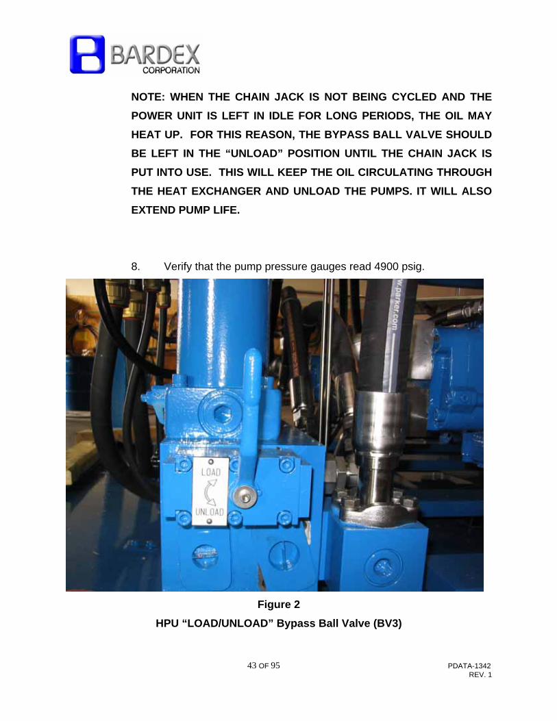
4. Open the bypass valve, BV3 to “UNLOAD” the pumps. This valve is
located on the right hand side (as viewed facing the electrical
control panel) down low near the interface 4-bolt flange Supply and
Return connections. See Figure 2
5. Check the main pump suction gauge. Because the reservoir is
above the pump there should be a positive head (pressure) reading
on the gauge (approximately 0.5 to 2.0 PSI).
6. Start each pump. Immediately check the suction gauge and verify
that it is not pulling a vacuum. If the gauge reads too much vacuum
(lower than –0.5 PSI), stop the pump. Stop motor immediately if
a loud cackling sound is emitted from the pump indicating that
cavitation is occurring. Jogging the pump on and off several
times may be necessary to purge the air out during initial start-up.
CAUTION: CAVITATION IN THE PUMP CAN LEAD TO
CATASTROPHIC PUMP FAILURE.
7. In anticipation of using the Chain Jacks, close the bypass ball valve
slowly to “LOAD”. Pressure will increase to full operating pressure
and flow will cease to pass through the heat exchanger until the Chain
Jack is cycled.
43 OF 95 PDATA-1342 REV. 1
NOTE: WHEN THE CHAIN JACK IS NOT BEING CYCLED AND THE
POWER UNIT IS LEFT IN IDLE FOR LONG PERIODS, THE OIL MAY
HEAT UP. FOR THIS REASON, THE BYPASS BALL VALVE SHOULD
BE LEFT IN THE “UNLOAD” POSITION UNTIL THE CHAIN JACK IS
PUT INTO USE. THIS WILL KEEP THE OIL CIRCULATING THROUGH
THE HEAT EXCHANGER AND UNLOAD THE PUMPS. IT WILL ALSO
EXTEND PUMP LIFE.
8. Verify that the pump pressure gauges read 4900 psig.
Figure 2
HPU “LOAD/UNLOAD” Bypass Ball Valve (BV3)

44 OF 95 PDATA-1342 REV. 1
5.2 Chain Jack Operation
IMPORTANT NOTE: BARDEX RECOMMENDS ALWAYS USING TWO (2)
CHAIN JACK OPERATORS FOR ALL CHAIN JACKING. ONE OPERATOR
SHALL OPERATE THE CONTROL CONSOLE AND THE OTHER WATCHES
THE CHAIN JACK OPERATION TO ENSURE BOTH LATCHES ARE CLOSED
WHEN LIFTING OR HOLDING THE CHAIN. DO NOT ATTEMPT TO LATCH,
JACK, LIFT OR HOLD THE CHAIN WITH ONE LATCH OPEN AND ONE
LATCH CLOSED. FAILURE TO CONFIRM BOTH LATCHES ARE CLOSED
WHEN HOLDING OR JACKING THE CHAIN MAY RESULT IN DAMAGE.
5.2.1 General
The Chain Jacks are operated at the control console by using the
control valve handles in the proper sequence. Refer to Figures 3
and 4 which illustrate the Chain Jack Assembly “Haul In” and “Pay
Out” sequential steps, respectively.
Chain Jack Operating Speed:
The mooring system has been designed with one dedicated
hydraulic power unit operating one jack at the speed listed below.
Except for regular maintenance to confirm the speed settings no
adjustments of the flow controls are required for normal operation.
Because the hydraulic power unit has two redundant pumps, half
speed can be attained if only one pump is operational without
damage or reduction in load capacity.

45 OF 95 PDATA-1342 REV. 1
The Chain Jack operates at 3.1 ft/min for “Haul In” or 2.5 ft/min for
“Pay Out”.
Steps required for Chain Jack operation:
1. Connect HPU to control console and chain jack per DWG-
102186, Hydraulic Schematic.
2. Connect 460VAC and 120 VAC power to the HPU per DWG-
102180, Electrical Schematic. Perform checkout per Section
3.4.
3. Connect 120 VAC power to the electrical enclosure per
DWG-102180, Electrical Schematic. Perform checkout per
Section 3.4. Turn the power switch to “ON”. The display will
illuminate and show the load on the stopper. Note: Refer to
Section 6.9.1 which describes additional display features.
4. Ensure pump suction line ball valves are open and the
bypass ball valve BV3 is in the “UNLOAD” position, then
start HPU motor/pumps.
5. Slowly shift bypass ball valve, BV3 to “LOAD”. Operate the
Chain Jack as described in Sections 5.2.2 through 5.2.4.
5.2.2 Chain Jack Assembly Latch Positions

46 OF 95 PDATA-1342 REV. 1
The Chain Jack Assembly is designed to “Haul-In” or “Pay-Out”
mooring line by moving the chain one chain pitch (2 links) at a time.
This is accomplished by stroking the Chain Jack Lift Cylinders and
operating latches, successively, at four defined stroke positions.
There are two positions for operating the traveling latches
(designated as traveling latch windows) when the load is on the
fixed latches (position 2 and position 4). In these positions, the
chain is held clear of the traveling latches allowing them to be
opened or closed without interference.
There are two positions (designated as fixed stopper windows) for
operating the fixed latches while the load is on the traveling latches
(position 1 and position 3). In these positions, the chain is held
clear of the fixed latches allowing them to be opened or closed
without interference.

47 OF 95 PDATA-1342 REV. 1
Figure 3-“Haul In” Sequence

48 OF 95 PDATA-1342 REV. 1
Figure 4-“Pay Out” Sequence
49 OF 95 PDATA-1342 REV. 1
CAUTION: ALWAYS LEAVE THE CHAIN ON THE CHAIN STOPPER
(FIXED LATCHES) DURING IDLE PERIODS OF OPERATION.
5.2.3 HAUL-IN (Raise Chain)
Refer to Figure 3
The raise sequence given below may be started at any position in
the sequence. The steps given below are based on starting from
the Chain Jack Park position (lift cylinders fully retracted with the
chain resting in the fixed latches). See Section 5.1 for HPU starting
instructions.
Refer to DWG-102181; View A-A for Control Console
nomenclature.
1. Shift the lift cylinder Directional Control Valve (DCV) to "CYL
LOWER" and extend the cylinder to the fully extended
position. Release valve handle. (Position 4 in Figure 3)
2. The traveling latch DCV is spring offset to close latches
without operator intervention. Ensure visually that BOTH
latches fully close before continuing.

50 OF 95 PDATA-1342 REV. 1
NOTE: DURING THE “HAUL IN” SEQUENCE, IT IS NOT
NECESSARY TO MANUALLY OPEN THE FIXED (STOPPER)
LATCHES AS THEY WILL RATCHET OPEN DURING CHAIN
PASSAGE. IT IS ONLY NECESSARY TO ENSURE THAT THEY
ARE CLOSED (BY OPERATING THE MANUAL VALVE) AND IN
THE PROPER POSITION BEFORE LANDING THE CHAIN.
3. Shift the lift cylinder DCV to “CYL RAISE” and retract the
Chain Jack to Position 1 (Fully retracted). This lifts the chain
one pitch (two links).
4. The stopper DCV is spring offset to “CLOSE STOPPER” so
the stoppers (fixed latches) will close without operator
intervention. Release the lift cylinder DCV handle when the
stoppers are fully engaged. Verify both stoppers are closed
before releasing the handle.
5. Push the “CYL LOWER” DCV lever to extend the lift
cylinders. The chain tension will transfer to the stopper
(fixed latches) as the lift cylinder continues to extend to the
next chain pitch. It is not necessary to shift the Latch DCV to
“OPEN” as they “ratchet” along the chain links. Extend the
cylinders all the way to Position 4.
6. Repeat Steps 1 through 5 to continue hauling in (lifting)
chain.
51 OF 95 PDATA-1342 REV. 1
IMPORTANT: THE CHAIN JACK ASSEMBLY SHOULD ALWAYS
BE PLACED IN THE PARK POSITION (LIFT CYLINDERS FULLY
RETRACTED WITH THE CHAIN LOAD ON THE FIXED
STOPPER AND THE TRAVELING LATCHES RESTING ON THE
CHAIN) WHEN JACKING OPERATIONS HAVE BEEN
COMPLETED.
CAUTION: ALWAYS LEAVE THE CHAIN ON THE CHAIN
STOPPER (FIXED LATCHES) DURING IDLE PERIODS OF
OPERATION.
IMPORTANT: SHIFT THE BYPASS BALL VALVE ON THE HPU
TO “UNLOAD” DURING IDLE PERIODS OF OPERATION.
5.2.4 PAY-OUT (Lower Chain)
Refer to Figure 4
The lowering sequence may be started at any position in the
sequence. The steps given below are based on starting with the
Chain Jack in the “Park” position (Chain jack fully retracted with the
chain resting in the fixed stopper), Position 1 in Figure 4.

52 OF 95 PDATA-1342 REV. 1
1. Shift the lift cylinder DCV to "CYL LOWER" to extend the
Chain Jack lift cylinder approximately 6 inches. When the
traveling cross arm reaches Position 2, both traveling latches
will close without operator intervention. Release the lift
cylinder DCV lever. If position 2 has been reached, the
traveling latches will be closed.
2. Verify that both traveling latches are closed by visual
examination before continuing.
WARNING: ALWAYS BE SURE BOTH LATCHES ARE CLOSED
ON THE UNDERSIDE OF THE CHAIN LINK BEFORE
CARRYING THE LOAD.
3. Retract the Chain Jack lift cylinders to Position 1, (cylinder
fully retracted), by pulling the lift cylinder DCV lever to "CYL
RAISE". Hold the valve in the “CYL RAISE” position until
the chain clears the stopper latches.
4. Open the Chain Stopper by shifting the DCV lever to “OPEN
STOPPER”. Verify both fixed latches are open by visual
observation. Hold control lever to maintain stoppers open.
WARNING: STOPPER LATCHES WILL CLOSE IF THE
CONTROL LEVER IS RELEASED.
5. Extend the Chain Jack and pay out chain until chain is past
the stopper by shifting the DCV lever to “CYL LOWER”

53 OF 95 PDATA-1342 REV. 1
6. When the first chain pitch (2 links) has moved down enough
to clear the stopper latches, Position 3 close the Chain
Stopper (release the stopper lever so it springs back into the
“CLOSE STOPPER” position).
7. Continue to extend the Chain Jack until the chain is held in
the stopper and the traveling latches are free to open
(Position 4), by shifting the DCV lever to "CYL LOWER".
Verify chain is supported by the stopper.
8. Open the Traveling Latches by shifting the lever to “OPEN
LATCH”. Hold latches open.
9. Retract the Chain Jack lift cylinder by shifting the DCV lever
to “CYL RAISE”. Continue to Position 2 while maintaining the
lever in the “LATCH OPEN” position.
10. Release Traveling Latch DCV lever to “CLOSE LATCH” to
close latches.
11. Repeat Steps 3 through 10 to continue the pay-out
sequence.
54 OF 95 PDATA-1342 REV. 1
IMPORTANT: THE CHAIN JACK ASSEMBLY SHOULD ALWAYS
BE PLACED IN THE PARK POSITION (LIFT CYLINDERS FULLY
RETRACTED WITH THE CHAIN LOAD ON THE FIXED
STOPPER AND THE TRAVELING LATCHES RESTING ON THE
CHAIN) WHEN JACKING OPERATIONS HAVE BEEN
COMPLETED.
CAUTION: ALWAYS LEAVE THE CHAIN ON THE CHAIN
STOPPER DURING IDLE PERIODS OF OPERATION.
IMPORTANT: SHIFT THE BYPASS BALL VALVE ON THE HPU
TO “UNLOAD” DURING IDLE PERIODS OF OPERATION.
6.0 MAINTENANCE
6.1 General Maintenance and Schedule
Maintenance in the field should be limited to general assembly
maintenance, trouble shooting, and component replacement. Component
overhaul or refurbishment is best left to the Bardex factory shops which
are equipped with the necessary machinery and qualified personnel.
IMPORTANT:
ALL MAINTENANCE SHOULD BE PERFORMED BY TRAINED AND
QUALIFIED PERSONNEL ONLY.

55 OF 95 PDATA-1342 REV. 1
Whenever the system is opened for any replacement or repair of
components, the following general precautions should be taken to avoid
contamination.
1. Plug, cap or cover any open piping, hose or valve mounting surface
to prevent the ingress of foreign substances.
2. Thoroughly clean all adjoining surfaces before disassembly.
3. New or repaired parts must be cleaned prior to re-assembly,
especially mating surfaces and areas around seals and gaskets.
Solvent cleaning followed by compressed air (dry and filtered)
drying of the parts works well.
NOTE:USING RAGS TO DRY PARTS USUALLY RESULTS IN SMALL
LINT PARTICLES ON THE SURFACES WHICH MAY BE
DETRIMENTAL TO PROPER SEALING AND MAY CONTAMINATE
HYDRAULIC FLUID.
4. Use drain pans and oil absorbing pads whenever possible to
minimize fluid spillage into the environment.
IMPORTANT: GOOD MAINTENANCE RECORDS AND PROCEDURES
ARE IMPORTANT TO ASSURE CONTINUOUS TROUBLE FREE
OPERATION.
The following maintenance schedule is provided as a guideline in
establishing an effective maintenance program. The time periods
indicated may be adjusted depending on the frequency of use, or
additional experience gained through periodic equipment inspection.
56 OF 95 PDATA-1342 REV. 1
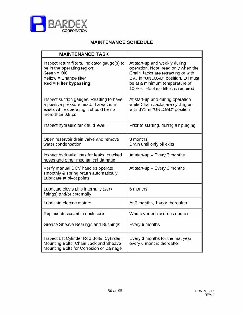
MAINTENANCE SCHEDULE
MAINTENANCE TASK
Inspect return filters. Indicator gauge(s) to be in the operating region: Green = OK Yellow = Change filter Red = Filter bypassing
At start-up and weekly during operation. Note: read only when the Chain Jacks are retracting or with BV3 in “UNLOAD” position. Oil must be at a minimum temperature of 100F. Replace filter as required
Inspect suction gauges. Reading to have a positive pressure head. If a vacuum exists while operating it should be no more than 0.5 psi
At start-up and during operation while Chain Jacks are cycling or with BV3 in “UNLOAD” position
Inspect hydraulic tank fluid level.
Prior to starting, during air purging
Open reservoir drain valve and remove water condensation.
3 months Drain until only oil exits
Inspect hydraulic lines for leaks, cracked hoses and other mechanical damage
At start-up – Every 3 months
Verify manual DCV handles operate smoothly & spring return automatically Lubricate at pivot points
At start-up – Every 3 months
Lubricate clevis pins internally (zerk fittings) and/or externally
6 months
Lubricate electric motors
At 6 months, 1 year thereafter
Replace desiccant in enclosure
Whenever enclosure is opened
Grease Sheave Bearings and Bushings
Every 6 months
Inspect Lift Cylinder Rod Bolts, Cylinder Mounting Bolts, Chain Jack and Sheave Mounting Bolts for Corrosion or Damage
Every 3 months for the first year, every 6 months thereafter

57 OF 95 PDATA-1342 REV. 1
MAINTENANCE TASK
Inspect Fixed & Traveling cross arms, Latch Contact Surfaces and Bearing Inserts. Surfaces to be free of debris and excessive peening
Every 3 months and after pulling a chain with heavy marine growth through the chain jack.
Extend and Retract Lift Cylinders and Latch Cylinders for 15 Minutes. Inspect Cylinder Rods for Excessive Rod Seal Leakage
Cycle the chain jack cylinders at least once every 3 months.
Inspect Chain Contact Surfaces for Wear
6 months
Inspect hydraulic fluid by having a fluid sample analyzed by an independent laboratory.
As recommended by the fluid manufacturer; every 3 months for first year. Adjust interval as necessary
HPU Motor & connection Cable Megger
Every 6 months - Any time motor is disconnected. Always check motor rotation after disconnecting
Recalibrate HPU and Load indicating pressure gauges
Every 6 months
Check and/or Reset HPU system relief valve: RV1 = 5100 psi
Every 12 months

58 OF 95 PDATA-1342 REV. 1
MAINTENANCE TASK
MAINTENANCE INTERVAL
Check and/or Reset HPU pump(s) pressure compensator setting 4900 psi max
Check at every start-up and reset every 12 months
Check and/or Recalibrate system pressure control valves: Cyl. Raise = 4900 psi Cyl. Lower = 1000 psi Load Handling Valve = 4900 psi
As required. Pressure can be checked using test points supplied on the control console and chain jack
Check HPU Temperature Switches with a calibrated thermometer and heatsink
Yearly
6.2 Chain Jack Disassembly and Reassembly
Refer to DWG-102119, Chain Jack Assembly Detail
6.2.1 Traveling Crossarm Assembly Removal and Installation
1. The Chain Jack must be in the vertical position.
2. Remove and plug the hydraulic hose to the latch cylinder.
3. Support the weight of the traveling crossarm assembly
(approx. 1600 lbs) with rigging.
4. Remove the split flange retainer bolts on the cylinder rod
ends, then remove the retainer halves.
5. Lower the traveling crossarm assembly off the rod ends.
Insure concentric bushings, item 4 on DWG-102119 are retained.

59 OF 95 PDATA-1342 REV. 1
6. For reassembly reverse the above operations. Grease the
rod-bushing interface, then torque the split flange retainer bolts per
TS-1007.
6.2.2 Lift Cylinder Removal and Installation
NOTE: Removal of the lift cylinder(s) requires that the chain be supported
by the stopper (fixed latches). This repair effort should be planned in
advance when the chain jack is not in use.
1. Retract the cylinder completely. Use a cable rigging attached
from the fixed crossarm (or structure) to the traveling
crossarm to retract the cylinders by pulling up the crossarm.
2. Support the lower crossarm with a cable to secure it before a
cylinder is to be removed. See Step 7.
3. Disconnect/Lockout HPU from power source.
4. Relieve trapped pressure in the lift cylinder and manifold by
loosening the fittings on the Chain Jack tubing. Use a
suitable container to catch the oil.
WARNING:

60 OF 95 PDATA-1342 REV. 1
EXTREME CARE SHOULD BE TAKEN WHEN LOOSENING ANY
HYDRAULIC LINE UNDER PRESSURE. ALWAYS RELIEVE
PRESSURE BEFORE DISCONNECTING OR DISASSEMBLING
ANY HYDRAULIC COMPONENT. FAILURE TO RELIEVE
PRESSURE DURING DISASSEMBLY MAY RESULT IN
PERSONNEL INJURY OR DEATH.
5. When the pressure is relieved, remove the rod end tubing
and plug or cap the open ports to prevent further oil loss.
6. Remove, plug, and cap the piston side cylinder tubing.
7. Secure the traveling crossarm to the underside of the Chain
Jack foundation to support the weight of the crossarm when
the cylinder rod is disconnected. This rigging should be
made to level the crossarm which will ease the removal and
re-installation of the rod.
8. Remove the split flange retainer bolts, then the retainer
halves.
9. Attach a lifting sling to the top of the cylinder using the lift
eye provided.
10. Remove the lift cylinder mounting hardware at the fixed
crossarm.
61 OF 95 PDATA-1342 REV. 1
11. Slowly lift the cylinder assembly free of the crossarm
assemblies. Note radial orientation of bolt pattern with
respect to hydraulic lines for reinstallation later. (Note:
mounting flange bolt pattern allows only two installation
positions, correct and 180 degrees out).
CAUTION:
LIFT THE CYLINDER SLOWLY AND STRAIGHT TO AVOID ROD
PLATING DAMAGE OR DAMAGE TO OTHER CHAIN JACK
COMPONENTS.
12. To install the cylinder, reverse the above steps. Observe
bolt torque recommendations in TS-1007.
13. After installation operate the Chain Jack at low pressure a
few times to purge air and check for leaks. Refer to
Commissioning Section 3.2.2 for more details on re-
commissioning Chain Jacks.
6.2.3 Stopper and Latch Removal and Installation
NOTE: ONLY ONE SET OF LATCHES (FIXED STOPPERS OR
TRAVELING LATCHES) CAN BE REMOVED AT ONE TIME
SINCE THE CHAIN MUST BE SUPPORTED ON THE OTHER
SET.
Refer to DWG-102122 (Fixed Crossarm Assembly) or DWG-
102140 (Traveling Crossarm Assembly).

62 OF 95 PDATA-1342 REV. 1
1. Transfer the chain to the latches not being removed. If the
fixed latches are being removed, extend the Jack completely
before starting. This will ensure that the mooring load is not
held on hydraulic pressure but mechanically.
2. Remove the latch cylinder assembly, item 10 (on the Fixed
Crossarm Assembly) or item 8 (on the Traveling Crossarm
Assembly) rod end and piston end pins. Remove the entire
latch cylinder with hydraulic hoses still connected.
3. Disengage the timing link arm, item 13 (on the Fixed
Crossarm Assembly) or item 13 (on the Traveling Crossarm
Assembly) by first removing the retaining ring from the pin at
one end. Alternately, remove both pins and remove the link
arm completely.
4. Remove the hex plug then install a lifting eye (1/2-13 thread)
into the threaded hole on top of either style latch. Attach a
lifting sling.
5. Remove the torsion spring arm (retainer), item 19 (on the
Fixed Crossarm Assembly) or item 24 (on the Traveling
Crossarm Assembly) from the latch shaft ends. Remove the
torsion springs.
6. Remove the latch shaft dowel pin(s), item 24 (on the Fixed
Crossarm assembly) or item 26 (on the Traveling Crossarm
assembly).

63 OF 95 PDATA-1342 REV. 1
A. For the Fixed Latches (Stoppers), remove the latch
dowel retainer hardware then the retainer. Next, open
the latch and use a punch to drive the dowel pin out
from below. Note that there is a dowel pin on one ear
of each latch only.
B. For the Traveling Latches remove the latch dowel
retainer hardware then the retainer. Open the latch
and use a punch to drive the single dowel pin out from
below.
6. Remove the Latch shaft by pushing it out from the torsion
spring side while supporting the latch with a crane or block
and tackle from above. Ensure the shaft and linkage hubs
which are still attached are secured safely to the crossarm or
deck.
7. Lift the latch clear.
8. Reverse the above steps to install. Grease bearings and
dowel pins upon re-assemble.

64 OF 95 PDATA-1342 REV. 1
6.3 Chain Jack Cylinder Seal Replacement
Refer to DWG-102170, Lift Cylinder Assembly. Lift cylinder is assumed to
previously have been removed. See section 6.2.2.
Disassemble the cylinder in a clean location. An overhead crane is
required.
Each part should be thoroughly cleaned. If the cylinder is to be dismantled
for any length of time, coat the metal parts which are to be re-used, with
good rust preservative and store in a protected area. The cylinder must be
stored in its retracted position to prevent damage and corrosion to the
critical surfaces.
1. Be sure to plug and protect all hydraulic connections opened during
this activity.
2. Attach an appropriate sling to the lifting eye located on the cylinder
blind end. Connect an overhead hoist to the lifting sling and remove
slack. Note cylinder weight is approximately 1800 lbs.
3. Lift the cylinder off the crossarm and place on the deck. Move the
cylinder to an appropriately clean work area.
4. Using filtered and dry compressed air, extend the cylinder
completely and expel the residual oil from the rod end. Use hoses
to direct oil to a suitable container. Do not re-use this oil. Using the
compressed air, retract the cylinder completely and expel oil from
the blind end.

65 OF 95 PDATA-1342 REV. 1
5. Invert the assembly (rod end up) and support on blocking.
6. Remove the retaining hardware (18X Socket Head Cap Screws)
from the gland and baseplate ends of the cylinder. Remove
baseplate and gland using rubber mallet to tap out if necessary.
7. Remove the piston/rod assembly. With chrome protected, secure
rod in clamping mechanism.
8. Using 3/8” center punch, remove the roll pin in the piston nut. Heat
with a torch at low heat (325ºF) to loosen thread sealer (Loctite
262). Remove piston nut and any excess loctite from piston and
rod with a wire brush. Remove piston from rod.
9. Place on a clean flat surface covered with a clean lint-free cloth.
Inspect all components for cracks, scratches and wear. Inspect all
seal grooves. Clean each component thoroughly.
10. Remove all seals using a blunt, tapered tool of any material softer
than aluminum (wood or plastic). Wedge beneath seal and pry off.
Be careful not to score any sealing (sealing ring groove) surfaces.
11. Replace all seals and bearings in gland, base plate and piston.
Ensure all seals are properly installed with respect to the direction
of pressure shown on DWG-102170. Lubricate all seals and seal
swept areas with clean hydraulic fluid. Do not install seals when
there is any doubt as to seal or surface integrity.
66 OF 95 PDATA-1342 REV. 1
12. With seals and bearings in place, install gland from piston end of
rod. Slide stop ring, spacer and piston back on piston rod. Apply
Loctite 262 to piston nut and rod threads. Tighten such that roll pin
can be re-installed. Install piston seals and bearings.
13. Apply a thin coat of hydraulic fluid to the rod and piston assembly.
Re-install rod assembly into gland end of cylinder tube. Lubricate
the bolt threads with molybdenum disulfide anti-seize compound.
Re-install bolts (7/8-14 UNF-2A Socket Head Cap Screws) in both
the gland and baseplate. Torque to 670 ft-lbs. via a criss-cross
pattern.
14. Connect the cylinder to the hydraulic power unit. Carefully extend
and retract the cylinder several times to fill with (filtered) oil and
expel air. Pressure required to stroke the cylinder should not
exceed 300 psi.
Proof Testing
After a cylinder has been completely re-assembled, test it at low
pressure in order to ensure that the rod is moving freely and is not
scored. Cycle the cylinder at least five (5) times in each direction to
ensure all air is purged out. Afterward increase the pressure to the
maximum recommended value (operating) and check for leakage.
15. Pressurize each end individually to operating pressure while
checking opposing end for leaks.
16. Re-install cylinder assembly onto Chain Jack. Connect all hydraulic
lines previously disconnected.
67 OF 95 PDATA-1342 REV. 1
CAUTION:
THERE MAY BE RESIDUAL PRESSURE TRAPPED IN THE
CYLINDER. LOOSEN FITTINGS SLOWLY AND USE EYE
PROTECTION.
6.4 Latch Cylinder Seal Replacement
1. The latch cylinders are standard small cylinders which operate at a
relatively low pressure compared to the rest of the system.
2. Remove and plug/cap the hydraulic hoses to the rod end and piston
end.
3. Remove the snap rings from one side of each clevis pin at the
latches and timing hubs; push out pins to remove cylinder.
4. Using a spanner wrench (1/4” pin in gland) unscrew the gland (end
cap at rod end); disassemble the remaining cylinder components.
5. Remove all seals using a blunt, tapered tool made of any material
softer than aluminum (i.e., wood or plastic).
6. Clean all cylinder components using solvent, dry, filtered
compressed air and lint free cloths. Inspect all sealing surfaces
including O-ring grooves and cylinder bores for nicks and
burnishing.
68 OF 95 PDATA-1342 REV. 1
7. Apply a thin coat of hydraulic fluid to sealing surfaces and moving
parts. Reassemble using new seals.
8. Replace hoses and leak test in both the extend and retract
directions.
9. Install cylinder on chain jack linkage, install and lubricate pins.
Replace chain jack hoses and repeat leak testing.
6.5 Hydraulic Power Unit Filter Maintenance (Return, Pressure and Suction)
NOTE: AFTER USING THE HYDRAULIC POWER UNIT OVER A
PERIOD OF TIME, THE EQUIPMENT OPERATOR WILL GET A FEEL
FOR THE NUMBER OF HOURS THE UNIT CAN RUN BETWEEN
SUCCESSIVE OIL FILTER ELEMENT CHANGES BY OBSERVING THE
FILTER INDICATORS.
While the HPU is idling in the “LOAD” condition (running but no equipment
operating), the pump compensator has stroked the pump back to zero
flow. There is output flow only when equipment is actually operating or
when the bypass ball valve (BV3) is in the “UNLOAD” position. Therefore,
the filter indicators must be checked while equipment is operating, or with
the bypass valve, BV3 open in the “UNLOAD” position (and oil above
100ºF).
NOTE: ALL FILTER INDICATORS READ HIGH WHEN THE OIL IS
COLD. AS THE OIL WARMS UP TO THE PROPER OPERATING
VISCOSITY, INDICATORS WILL READ LOWER VALUES.
69 OF 95 PDATA-1342 REV. 1
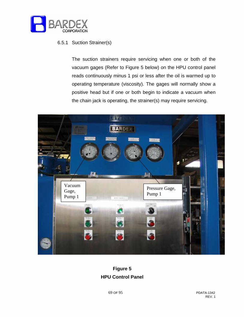
6.5.1 Suction Strainer(s)
The suction strainers require servicing when one or both of the
vacuum gages (Refer to Figure 5 below) on the HPU control panel
reads continuously minus 1 psi or less after the oil is warmed up to
operating temperature (viscosity). The gages will normally show a
positive head but if one or both begin to indicate a vacuum when
the chain jack is operating, the strainer(s) may require servicing.
Figure 5
HPU Control Panel
Vacuum Gage, Pump 1
Pressure Gage, Pump 1

70 OF 95 PDATA-1342 REV. 1
The strainers are located inside the reservoir tank and can be
serviced by removing the access cover from the tank (Refer to
DWG-102194). Note that the tank must be drained prior to
removing the covers.
To service the strainer elements;
1. Drain the reservoir to below the access cover level.
2. Close the suction ball valves to the pumps.
3. Remove access cover from the reservoir.
4. Unscrew strainer elements to be replaced.
5. Replace with new elements.
6. Reinstall the access cover and gasket and refill the reservoir.
Be sure to refill the reservoir using filtered hydraulic fluid.
New fluid from the barrel usually does not meet cleanliness
requirements.

71 OF 95 PDATA-1342 REV. 1
7. With the power unit off, open the suction valve(s) and check
the suction gauge(s). Because the reservoir is above both
pumps there should be a positive head (pressure) reading
on the gauge(s), of approximately 0.5 to 2.0 psi, dependent
on the location of the suction indicator. However, since the
suction gauges are above the pumps, the reading may be
zero or slightly negative. The initial value should be noted for
comparison to the value seen when pumps are at full flow
with suction ball valves properly opened and clean strainers.
Knowing the initial value can be used to trouble shoot
clogged strainers or slightly closed suction valves for
example (gauge reading would go more negative when
pumps come on full stroke).
8. With the bypass ball valve, BV3 in the “UNLOAD: position,
start each pump separately. Immediately check each
suction gauge and verify that it is not pulling a vacuum. If the
gauge reads too much vacuum (lower than –0.5 PSI below
the initial value), stop the pump. Stop motor immediately if
a loud cackling sound is emitted from the pump
indicating that cavitation is occurring. Jogging the pump
on and off several times may be necessary to purge the air
out during initial start-up.
NOTE: UPON INITIAL START UP OF THE MOTOR/PUMP ASSEMBLY
AFTER AN ELEMENT SERVICE, JOG START EACH MOTOR THREE TO
FOUR TIMES TO DRAW ALL AIR OUT OF THE LINE.

72 OF 95 PDATA-1342 REV. 1
CAUTION: OPERATION OF MOTOR/PUMP ASSEMBLY WITH SUCTION
LINE BALL VALVE CLOSED WILL CAUSE SERIOUS DAMAGE TO THE
HYDRAULIC PUMP. RECOMMEND RE-AFFIXING THE TAGS
INSTALLED ON THESE VALVES PER SECTION 5.0
6.5.2 Return Filter
The return filter is mounted directly on the top of the reservoir. The
filter indicator is located on the filter housing (See Figure 6). After
the oil is warmed to operating temperature, the pressure drop
across a filter is a function of flow through the element and element
resistance. Element resistance increases with accumulation of
residue.
With a new element in place and oil warmed to normal operating
temperature (100º-120ºF) very little pressure drop is indicated.
To check element condition:
1. Start each motor/pump assembly per Step 8 of the previous
section.
2. Allow oil to warm up to operating temperature.
73 OF 95 PDATA-1342 REV. 1
3. With BV3 in the “LOAD” position, hold the traveling latch
open continuously, then extend and retract one of the Chain
Jacks with no (chain) load. After extending, shifting the lift
cylinder DCV to “CYL RAISE” will send flow through the
return filter (Alternatively, shift BV3 to “UNLOAD” and send
full pump flow through the applicable filter)
4. Check the return filter indicator. At this point, if the filter
indicator is operating in the red, change the element.
To change return filter element:
1. Shut off power unit, and locate the return filter. (Refer to
DWG-102194 and Figure 6).
2. Loosen the bolts on the filter top. Remove the top and find
the filter. Note: The reservoir tank does not need to be
drained to replace a return filter.
3. Remove old filter element. Replace element with new one.
Ensure filter element seats properly in housing.
4. Replace top and hardware then tighten all bolts.

74 OF 95 PDATA-1342 REV. 1
Figure 6
Return Filter Indicator and Pressure Gauge
6.5.3 Pressure Filters
The pressure filters, F3 and F4, are connected just downstream of
each pump. They are located on the manifold adjacent to the
bypass ball valve, BV3. Refer to drawing 102194. The filter
indicators operate in much the same way as the return filter
indicator.
To change pressure filter element:
Return Filter Indicator Gauge RED ZONE

75 OF 95 PDATA-1342 REV. 1
1. Shut off the power unit, and close the suction line ball valve
for the particular circuit. (Refer to DWG-102194).
2. Loosen the filter cover by unscrewing (note two pins which
are used to apply torque to cover). Remove the cover and
find the filter. Note: The reservoir tank does not need to be
drained to replace these filters as long as the applicable
suction line ball valve has been closed per above step.
3. Remove old filter element. Replace element with new one.
Ensure filter element seats properly in housing.
4. Replace cover and then tighten snugly.
5. Open suction ball valve(s) which was closed in step 1.
6.6 PRESSURE CONTROL AND ADJUSTMENT
Several features are provided in the system for pressure control and for
smooth and stable operation.
1. Each identical pump is torque limited and pressure
compensated. Pumps are controlled by a compensator
setting (RV2, RV3 set @ 4900 psi).
2. A main relief valve, (RV1 set @ 5100 psi) located on the
pressure filter manifold near the bypass ball valve (BV3)
protects the system. See drawing DWG-102194 for exact
location.

76 OF 95 PDATA-1342 REV. 1
6.6.1 To Adjust the HPU Pressure Controls
See DWG-102194 and Figure 7 below:
Figure 7
Pump (Note: shaft connects to motor, not shown)
1. The pump compensator adjustor can be found on the control
block located on each pump. It can be adjusted by loosening
the lock nut and turning the adjustment screw with an Allen
wrench. With the pump motor running and the bypass ball
valve, BV3 closed or in the “LOAD” position, decrease the
setting by turning it counter clockwise until system pressure
begins to fall. Then increase the setting until the correct
pressure reads on the pressure gauge. If pressure does not
increase, check the setting of the main system relief valve. If
it is too low, it will not allow pressure to build.
Pump Compensator Adjustor

77 OF 95 PDATA-1342 REV. 1
2. The main system relief valve, RV1 is located on the side of
the main manifold behind the bypass ball valve, BV3. It can
be set by loosening the lock nut and turning the adjustment
screw with an Allen wrench. Turning the screw
counterclockwise decreases the setting while turning it
clockwise increases the setting. The main system relief valve
should be set approximately 200 PSI higher than the pump
compensator setting. The pump compensator can be
adjusted high enough to achieve this setting temporarily, but
it should be turned back down to normal operating pressure
after the relief valve has been set.
3. The load holding valve setting is best left to a Bardex factory
representative. However, RV2 on the Chain Jack manifold
can be adjusted if necessary as follows:
A. Shift Control Console lever to “CYL RAISE” to retract
the cylinders all the way.
B. With the pump pressure adjusted up to 5200 psi check
that RV2 dumps cylinder pressure at 5100 psi with
valve held in the “CYL RAISE” position. If not, adjust
by loosening the lock nut and turning the adjustment
screw with an Allen wrench. Turning the screw
counterclockwise decreases the setting while turning it
clockwise increases the setting. Once adjustment has
been made, tighten the lock nut.

78 OF 95 PDATA-1342 REV. 1
6.7 AIR PURGING PROCEDURE
Refer to Technical Bulletin TB-2015 included in the Appendix for air
purging guidelines for typical Bardex equipment. Chain jack operation at
low pressure will effectively purge air from the cylinders and hoses. The
power unit should be set as low as possible but high enough to open the
load holding valve and lift the weight off the traveling crossarm
(approximately 1000 psi). At lower pressures the cylinders may not
retract.
At least twenty (20) cycles of each cylinder is sufficient to bleed air out of
the system.
6.8 LUBRICATION
The system is mostly self-lubricating during normal operation as most of
the moving parts are lubricated by hydraulic oil in the system with the
exception of the electric motor, sheave bearings, latch shafts, and the
latch cylinder pins.
Whenever any equipment is disassembled for any reason, appropriate
parts should be lubricated during re-assembly. Threads of all assembly
mounting bolts should be coated with molybdenum disulfide (Moly-Lube
550 or equivalent).
Grease (zerk) fittings on the latch cylinder pins and sheave axles should
be pumped full of white lithium marine grade grease.
79 OF 95 PDATA-1342 REV. 1
6.9 ELECTRICAL EQUIPMENT
6.9.1 Load Cell Display Instrumentation
Refer to DWG-102178, Load Cell Instrument Enclosure and Figure 8
The load cell display instrument is a pre-programmed logic device
which reads all four load cell inputs (two redundant load cell bridges
within each of the two load cells under opposing stoppers). It also
displays operational and normal (preset range) status of all four
load cell bridge inputs. In addition, it will indicate a fault condition in
any of the inputs, trigger an alarm and automatically adjust the
averaging function to neglect the faulted signal. Finally, an RS-485
serial communication link is provided for remote monitoring of the
display output and load cell (operational/normal) status at a remote
computer(s).

80 OF 95 PDATA-1342 REV. 1
The accuracy of the load cell display system is expected to be
better than 5% of full scale over the expected chain tension range
for which the load cell has been designed (820 kips), Above this
limit the display will continue to output a signal with a maximum
error of +/-5% of the normal range. However, as the mooring
tension approaches the chain yield point of 1230 kips, some type of
alarm is warranted. Therefore, at 10% above the chain yield point
(1350 kips) an overload alarm is triggered. The affected bridge(s) is
disabled at this load for the case of a failed bridge that may be
giving an erroneous value. The load cells will not provide an
accurate measurement value above the yield point of the chain. In
the event of extreme chain tension, a record/alert to this fact will be
made available. A disabled input which has occurred in this
scenario can be reset as the load cell will typically be undamaged
after the high load has been removed. The load cell may need to be
re-tared or re-zeroed by factory representatives. An example of
disabled bridge(s) status is shown in Figure 8 for LC1A and LC1B.
NOTE: IF THE MOORING SYSTEM EXPERIENCES LOADS
ABOVE THE NORMALLY EXPECTED LOAD RANGE, A BARDEX
FACTORY REPRESENTATIVE SHOULD INSPECT THE
EQUIPMENT AND THE LOAD INDICATION SYSTEM.
The load cell display system may require adjustment after chain
installation. With no load (no chain) in the chain jack and with the
fixed latches closed, the display value should read zero. This can
be accomplished by taring the instrument.

81 OF 95 PDATA-1342 REV. 1
When the Chain Jack is in use, the load cell display value in kips
(1kip=1000 lbs) should closely match the load shown on the Load
Indicating Pressure Gauge. Note that the Load indicating Pressure
Gauge will only be accurate when the load is completely on the
traveling cross arm (unless the traveling cross arm is fully extended
or retracted) and supported by the hydraulics. Be sure to take
readings with a still load. If the cylinders are lifting the chain,
dynamic friction will add to or subtract from the load depending on
cylinder direction. If the cylinders are fully extended the load will be
held mechanically and the load indication gauge will not be
accurate. If fully retracted, the pressure on the gauge will rise up to
full system pressure as adjusted at the pump(s).
The load cell display value will only be accurate when the chain is
fully resting on the fixed stoppers. It may be adjusted as described
below.
NOTE: THE LOAD CELL DISPLAY INSTRUMENT HAS BEEN
FACTORY SET FOR LOAD CELL SIGNALS OVER THE RANGE
OF EXPECTED MOORING TENSION. IT CAN AUTOMATICALLY
DETECT AN OUT OF RANGE (DEFECTIVE REDUNDANT LOAD
CELL BRIDGE WITHIN THE SEALED COMPRESSION LOAD
CELL). IF A FAULT IS DETECTED, THE DISPLAY VALUE
REMAINS ACCURATE BECAUSE THE FAULTY BRIDGE OR
OUT OF RANGE INPUT IS NEGLECTED. THE AVERAGING IS
ADJUSTED FOR THE FAULT AND AN ALARM CONDITION IS
INDICATED.
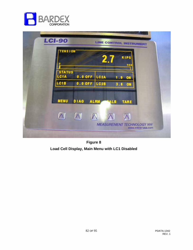
82 OF 95 PDATA-1342 REV. 1
Figure 8
Load Cell Display, Main Menu with LC1 Disabled
83 OF 95 PDATA-1342 REV. 1
The compression load cells and signal conditioners within the
electrical enclosure are factory set components and do not require
adjustment. However, the system may be “zeroed” or “tared” as
follows:
1. With no chain resting on the stopper ensure the stopper (latches
on the fixed crossarm) is in the closed position (latches resting
on the load cells).
2. Ensure the control console lever is in the “CLOSE STOPPER”
position (normal released position).
3. With the display enclosure switch in the “ON” position and the
security function OFF (see below), depress the keypad button
directly below the display window icon “TARE”. This will zero the
load measurement readout effectively subtracting the weight of
the stopper latches and the force exerted by the latch cylinder.
4. Re-enable the display instrument security function described
below.
NOTE: IT IS ADVISABLE TO ENABLE THE DISPLAY
INSTRUMENT SECURITY FUNCTION TO KEEP THE SYSTEM
CONSISTENT. THE SECURITY FUNCTION WAS NOT ENABLED
AS IT LEFT THE BARDEX FACTORY.
To enable the security function:

84 OF 95 PDATA-1342 REV. 1
1. Depress the keypad button directly below the display window
icon “MENU”. The screen will change to show four options,
depress the keypad button directly below the display window
icon “SYSTEM CONFIGURATON”.
2. Using the appropriate icon to move the arrow prompt to row 1
“SECURITY OFF”.
3. Depress the keypad button directly below the display window
icon “ENT”. This will highlight the default value (0=OFF, 1=ON),
and allow a security code to be entered. This code number can
be any value between 2 and 255, which will become the security
unlock code. Keep it in a safe place and enter it
here__________
4. Once a number is entered, depress the keypad button directly
below the display window icon “RUN” to save the change. The
security lockout feature is enabled and can only be disabled by
entering the same number.
5. Depress the keypad button directly below the display window
icon “MAIN” to return to the main (load display) menu.
The display screen has been designed to be viewed in broad daylight. It
has a built-in screen saver which causes the display to go blank after 30
minutes if the unit has not detected an operator key press. To re-energize
the display, simply depress any keypad button, preferably the MENU or
DIAG buttons on the left.

85 OF 95 PDATA-1342 REV. 1
6.9.2 Motor Wiring Megger Reading
Check motors at six-month intervals with a calibrated megohmeter.
Record megger readings, and if a drop in resistance is noted,
consult Bardex. All circuits had virtually infinite readings when
tested at the Bardex factory. Additionally, both main pump motors
have internal heater elements which are intended to drive moisture
away from motor windings.
7.0 SPARE PARTS
For a complete spare parts listing, see PDATA-1336 in the Appendix. For items
that do not appear in this listing, see Applicable Engineering Drawings in Section
9.0. Contact Support Services at Bardex via contact information given in the front
of this manual.
8.0 TROUBLE SHOOTING
CAUTION: TROUBLE SHOOTING PROCEDURES MAY EXPOSE
PERSONNEL TO HIGH PRESSURE AND TEMPERATURE HYDRAULIC OIL,
AND/OR HIGH VOLTAGES. TROUBLE SHOOTING PROCEDURES SHOULD
ONLY BE ATTEMPTED BY EXPERIENCED PERSONNEL UTILIZING
PROPER EQUIPMENT. STANDARD SAFETY PRACTICES AND EQUIPMENT
MUST BE ADHERED TO AT ALL TIMES.

86 OF 95 PDATA-1342 REV. 1
The purpose of this section is to establish basic trouble shooting procedures and
guidelines which can be used to identify sources of malfunctions in the system.
The depth of trouble shooting will depend on the training and experience of the
technician attempting to isolate or locate system faults. If the following
procedures do not result in isolation of fault, contact Bardex for additional
guidance or assistance.
8.1 BEFORE ASSUMING SYSTEM FAILURE:
1. Ensure that the system is properly installed and connected per
applicable installation procedures and engineering drawings for
each piece of equipment.
2. Check hydraulic lines for external leakage or mechanical damage.
3. Ensure that the selector valves are properly positioned and in the
full open or closed position, as applicable.
4. Ensure that the electrical system is not causing a system fault.
Ensure voltage and frequency regulation is correct.
5. Ensure that the Hydraulic Power Unit reservoir level is correct, oil is
clean and filters/strainers are not indicating a fouled or dirty
condition.
6. Check all equipment for unusual noises, odors, vibrations or
obvious external damage.

87 OF 95 PDATA-1342 REV. 1
8.2 TROUBLE SHOOTING PROCEDURES FOR HYDRAULIC POWER UNIT
1. Hydraulic pump cavitation (loud cackling noise emitted from the
pump).
A. Ensure suction valve(s) is fully open (i.e., handle(s) parallel
to piping).
B. Check suction indicator. This indicator shows a positive
pressure with the motor stopped and the suction line valve
open. It should not drop to more than a 0.5 psi vacuum with
the motor on and the chain jack cycling.
C. Check oil level.
D. Check oil type and weight. If oil viscosity is too high, pump
may cavitate.
2. Motor will not start
A. Oil level and/or temperature switch may have shut off
motor/pump. Check that the motor starters are enabled.
Check motor isolator/circuit breaker.
B. Check the motor starting wires and connections to ensure
that they are connected properly. Remove any corrosion
and moisture from terminals and contacts.
88 OF 95 PDATA-1342 REV. 1
C. Check the continuity of the starting wires and terminals.
D. Verify proper motor voltage and frequency.
3. Pump Motors Over-Heat
A. Check for proper motor voltage and frequency
B. Check for over heating of motor bearings
C. Check for motor to pump misalignment and proper
ventilation.
4. Oil Overheating
A. Ensure bypass valve BV3 position “UNLOAD” is selected
when chain jack is not cycling for long periods.
B. Ensure that heat exchanger is not clogged and fan is running
when oil warms up to operating temperature (warning
indicator will illuminate at the same time that the fan starts).
C. Ensure that the reservoir is within limits on sight gauge.
NOTE: WHEN RUNNING THE HPU FOR LONG PERIODS
WITHOUT USING THE CHAIN JACK, TURN THE BYPASS
VALVE, BV3 TO THE “UNLOAD” POSITION TO CIRCULATE
OIL THROUGH THE HEAT EXCHANGER.

89 OF 95 PDATA-1342 REV. 1
5. Low Pressure
A. Check all piping for external leakage.
B. Check suction strainer indicators (gauges) and pressure
gauges on HPU control panel.
C. Check pump compensator settings and system relief valve
settings.
D. Ensure BV3 is switched to “LOAD” to build pressure.
E. If all external lines are in good condition, all selector valves
are positioned correctly, the pumps may require servicing.
Contact factory representative for assistance.

90 OF 95 PDATA-1342 REV. 1
8.3 TROUBLESHOOTING PROCEDURES FOR CHAIN JACKS
1. Cylinders will not extend, load does not lower.
WARNING:
THE PILOT LINE MAY BE UNDER PRESSURE. SHUT THE POWER
UNIT OFF. CYCLE THE MAIN LIFT/LOWER CONTROL VALVE
SEVERAL TIMES WITH THE POWER UNIT OFF TO RELIEVE
PRESSURE PRIOR TO OPENING THE SYSTEM.
A. Check pressure in extend side of control valve in the console
by plumbing in a test gauge. It should be as indicated on the
hydraulic schematic.
B. Check load holding valve in-line filter inside load holding
valve manifold pilot port. If the filter is clogged, pilot pressure
may not reach the valve and shift it to allow flow out of the
cylinder.
2. Cylinders fail to retract, load is not raised.
A. Check that BV3 is in the “LOAD” position.

91 OF 95 PDATA-1342 REV. 1
B. Verify pressure registers on the gauge at the control
console. If pressure is low and the load does not move the
power unit may be malfunctioning. Refer to 6.6. Nominal
pressure is 4900 psi. This pressure will be indicated when
the cylinders are fully retracted with the valve held in the
“CYLINDER RAISE” position. Pressure is also seen at HPU
pressure gauges when BV3 is in the “LOAD” position.
C. Load is greater than the chain jack stall capacity of 550 kips.
3. Cylinders creep, extend slowly, with valve in neutral position.
A. Chain Jack relief valve set too low. Check for flow over the
valve. Listen for a hissing sound. Flow may also be
checked by holding onto the tubing immediately next to the
relief valve. If it is hot and vibrating, flow is present. See
section 6.6 for relief valve setting check.
B. Cylinder piston seals leaking. Refer to 6.3.
C. Load is greater than the chain jack stall capacity of 550 kips.
8.4 TROUBLE SHOOTING PROCEDURES FOR CONTROL CONSOLE
1. Low Pressure
A. Check all tubing for external leaks.
B. Ensure selector valves on Control Console and HPU are
correctly positioned and full over against mechanical stops.

92 OF 95 PDATA-1342 REV. 1
C. See Section 6.6 on pressure setting.
D. If all external lines are in good condition, all selector valves
are positioned correctly, and relief valve adjustment does not
correct for loss of pressure, the hydraulic power supply may
need attention.
2. Low Flow
A. Ensure that selector valves are properly positioned and full
over against mechanical stops.
B. Check for external leaks.
8.5 LOAD MONITORING SYSTEM
1. Load Indication Gauge reads different load (when chain is on
hydraulics) than load cell instruments indicate (when chain is on
stopper).
A. Check Load Indication (pressure) Gauge calibration. Re-
calibrate if necessary.
B. Open Load Cell Instrument Enclosure and inspect wiring and
that all signal conditioners lights are illuminated. (Green Power
ON normal; over range Red light may indicate a problem)
C. Re-tare the display with no chain load on the stopper.

93 OF 95 PDATA-1342 REV. 1
9.0 ENGINEERING DRAWINGS
DRAWING NUMBER TITLEDWG-102106 Chain Sheave Assembly DWG-102107 Chain Sheave Assembly Detail DWG-102115 Sheave Insert Assembly DWG-102118 Chain Jack Assembly-3-9/16” DWG-102119 Chain Jack Assembly Detail DWG-102122 Fixed Cross Arm Assembly DWG-102131 Latch Cylinder Assembly, Fixed DWG-102140 Traveling Cross Arm Assembly DWG-102146 Latch Cylinder Assembly, Traveling DWG-102158 Mooring System-3-9/16” DWG-102159 Mooring System Interface DWG-102170 Lift Cylinder Assembly DWG-102178 Load Cell Instrument Enclosure DWG-102180 Electrical Schematic – Mooring System
DWG-102181 Control Console Assembly DWG-102182 Control Console Assembly Detail DWG-102186 Hydraulic Schematic – Mooring System DWG-102188 Chain Jack Piping and Electrical Installation DWG-102194 Hydraulic Power Unit Assembly DWG-102246 HPU Electrical Enclosure PDATA-1336 WO-8387 Commissioning and 2 Year Spare Parts List

94 OF 95 PDATA-1342 REV. 1
APPENDIX


