
For your automation solutions
What’s new in 2019/2020


3
www.pilz.com/facebook www.pilz.com/youtube
www.pilz.com/linkedin www.pilz.com/twitter
www.pilz.com/xing
Pilz provides automation solutions for plant and machinery: complete and simple. From sensor technology to control and drive technology – with safety and automation included. Various software tools enable simple operation and make commissioning easier. Benefit from short downtimes and high plant availability due to extensive diagnostic options. Here we present our product innovations for 2019/2020 for your safe automation. Further information is available on our homepage at www.pilz.com. Simply enter the webcode listed on the following pages.
What’s new in 2019/2020 for your automation solutions
Contents
Rotary encoder PSENenco
for safe motion monitoring! 4
Modular safety gate system –
Your gate. Our system. Your safety. 6
Safety laser scanner PSENscan:
Light, master and slave versions 8
Safe protection zone monitoring
with radar technology 10
Safety relay PNOZsigma –
safe voltage monitor PNOZ s60 12
Safe small controllers PNOZmulti 2 –
the success story continues! 14
Safe small controllers PNOZmulti Configurator –
a simple safe drive solution 16
Safe small controllers PNOZmulti Configurator –
access permissions with PITreader 18
Safe small controllers PNOZmulti Configurator –
offline simulation 20
SecurityBridge protects Pilz controllers 22
Extended application range
for the remote I/O system PSSuniversal 2 24
Automated parameterization and
extended diagnostics thanks to IO-Link master 26
Operating mode selection and access
permission system PITmode fusion 28
Services:
Consulting, engineering and training 30
4
Rotary encoders
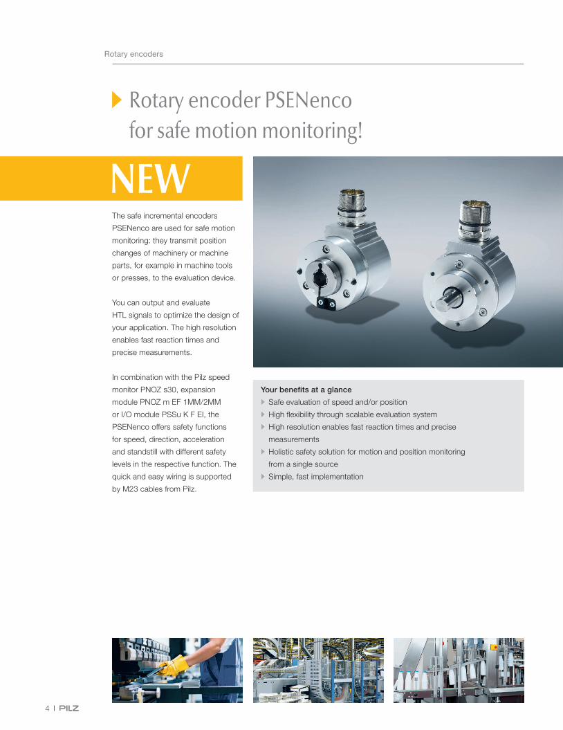
Rotary encoder PSENenco for safe motion monitoring!
The safe incremental encoders
PSENenco are used for safe motion
monitoring: they transmit position
changes of machinery or machine
parts, for example in machine tools
or presses, to the evaluation device.
You can output and evaluate
HTL signals to optimize the design of
your application. The high resolution
enables fast reaction times and
precise measurements.
In combination with the Pilz speed
monitor PNOZ s30, expansion
module PNOZ m EF 1MM/2MM
or I/O module PSSu K F EI, the
PSENenco offers safety functions
for speed, direction, acceleration
and standstill with different safety
levels in the respective function. The
quick and easy wiring is supported
by M23 cables from Pilz.
Your benefits at a glance
• Safe evaluation of speed and/or position
• High flexibility through scalable evaluation system
• High resolution enables fast reaction times and precise
measurements
• Holistic safety solution for motion and position monitoring
from a single source
• Simple, fast implementation
PowerIn1In2Rel1Rel2Fault
PNOZ s30
750330100762 1.1
IN1 IN2Y35 Y34 Y33 Y32 Y31Y13 Y12 Y11 Y10 Y30
X6
1112
2122
5
Webcode:
web150403
Rotary encoders
Online information at www.pilz.com
PSEN enc HTL 1024 ss
Type code for PSENenco
Product areaPilz SENsors
Rotary encoder feature Design Series
Product groupenc – PSENenco
HTL HTL signal 1024 Resolution per revolution hsss
Hollow shaftSolid shaft
OperationMagnetic and optical
Components for your safe solution Order number
Sensor: PSEN enc HTL 1024 hs 6Z000004
Connection: Signal line PSENcable M23-12sf 6Z000006
Evaluation device: PNOZ s30 - Spring-loaded terminals PNOZ m EF 1MM - Spring-loaded terminals PSSu K F EI
751 330750 330772 170703 542312 433
The appropriate solution including rotary encoder PSENenco for all scaling on the control side.
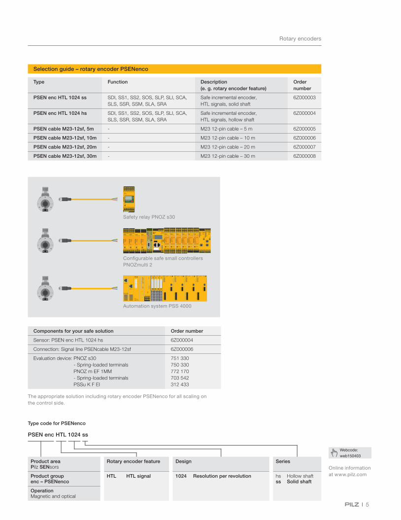
Selection guide – rotary encoder PSENenco
Type Function Description (e. g. rotary encoder feature)
Order number
PSEN enc HTL 1024 ss SDI, SS1, SS2, SOS, SLP, SLI, SCA, SLS, SSR, SSM, SLA, SRA
Safe incremental encoder, HTL signals, solid shaft
6Z000003
PSEN enc HTL 1024 hs SDI, SS1, SS2, SOS, SLP, SLI, SCA, SLS, SSR, SSM, SLA, SRA
Safe incremental encoder, HTL signals, hollow shaft
6Z000004
PSEN cable M23-12sf, 5m - M23 12-pin cable – 5 m 6Z000005
PSEN cable M23-12sf, 10m - M23 12-pin cable – 10 m 6Z000006
PSEN cable M23-12sf, 20m - M23 12-pin cable – 20 m 6Z000007
PSEN cable M23-12sf, 30m - M23 12-pin cable – 30 m 6Z000008
Safety relay PNOZ s30
Configurable safe small controllers PNOZmulti 2
Automation system PSS 4000

6
Modular safety gate system – Your gate. Our system. Your safety.
With our modular safety gate system,
we offer you an individual safety gate
solution that is ideally tailored to your
application. That means you can
combine the individual components
flexibly to suit your own particular
requirements. Benefit from an
economical series connection, rapid
diagnostics, additional control and
pushbutton elements and an optional
escape release.
The following components are
available for forming your modular
safety gate system:
• Safety gate sensor PSENslock
for safe position monitoring
with process guarding
• Safety gate sensor PSENmlock
for safe interlock and guard locking
in one product
• Escape release and suitable
handles for the safety gate system
PSENmlock
• Safety Device Diagnostics (SDD)
for comprehensive diagnostics
and economical series connection
of the safety gate sensors
PSENmlock
• Pushbutton unit PITgatebox
for simple operation of the
safety gate system
Modular safety gate system
Your benefits at a glance
• Individual solution tailored to the application
• Comprehensive modular portfolio
• Many different combination options
• High quality thanks to certification to common safety standards
• Quickly integrated into your plant
• Simple operation and maintenance
• A complete one-stop solution that's safe and economical
• Ideal for use in combination with safe control technology from Pilz

7
Webcode:
web194460
Modular safety gate system
Modular safety gate system
Online information at www.pilz.com
The heart of the modular safety gate system:
the safety gate sensors PSENslock and PSENmlock
Achieve safe position monitoring with process guarding with the safety gate
sensor PSENslock. It can be used up to the highest safety category and in
series connection.
The safety gate sensor PSENmlock offers safe interlock and guard locking
to PL e. The latter is enabled by the dual-channel control of the guard locking.
Connect PSENmlock in series and benefit from a low-cost installation. In
combination with Safety Device Diagnostics (SDD), individual switches or
gates can be controlled in a targeted manner – and all this without expensive
individual wiring in the control cabinet. In addition you also achieve simple
and comprehensive diagnostics of the safety switches, reducing downtimes.
As an optional accessory, two versions of escape release can be combined
with PSENmlock: a bar is used to connect the PSENml escape release directly
to the base unit, while the remote PSENml escape release cordset is mounted
on the PSENmlock via a pull-push wire. Whether it's for a swing gate or
sliding gate: we can offer you the right handle.
The perfect partner:
simple operation with
the pushbutton unit PITgatebox
Each preconfigured version with
various combinations of pushbuttons,
key switches and E-STOP push-
buttons gives you maximum flexibility
for your individual application. Thanks
to the slimline design, the robust
control unit can be installed quickly
and easily on standard profile
systems. The PITgatebox gives
you a modular safety gate solution
tailored to your particular needs,
especially when combined with
the secure safety gate systems
PSENmlock and PSENslock.
PSENslock PSENmlock
Sensor Series connection, 500 N
Series connection, 1,000 N
Base version Series connection
Optional: SDD
Escape re-lease
Escape release Remote escape release
Handles For swing gates For sliding gates
Pushbutton unit
PITgatebox
Further information and order numbers:
8
Safety laser scanners
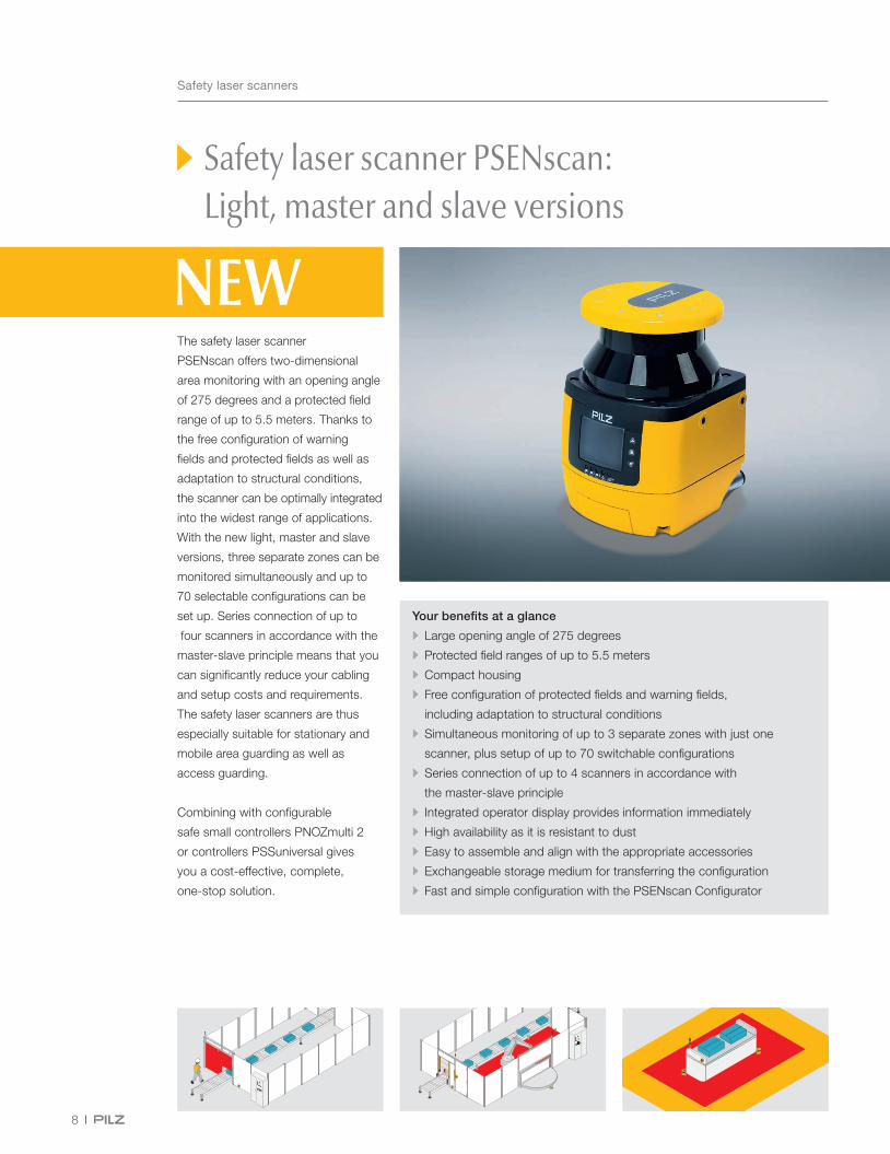
Safety laser scanner PSENscan: Light, master and slave versions
The safety laser scanner
PSENscan offers two-dimensional
area monitoring with an opening angle
of 275 degrees and a protected field
range of up to 5.5 meters. Thanks to
the free configuration of warning
fields and protected fields as well as
adaptation to structural conditions,
the scanner can be optimally integrated
into the widest range of applications.
With the new light, master and slave
versions, three separate zones can be
monitored simultaneously and up to
70 selectable configurations can be
set up. Series connection of up to
four scanners in accordance with the
master-slave principle means that you
can significantly reduce your cabling
and setup costs and requirements.
The safety laser scanners are thus
especially suitable for stationary and
mobile area guarding as well as
access guarding.
Combining with configurable
safe small controllers PNOZmulti 2
or controllers PSSuniversal gives
you a cost-effective, complete,
one-stop solution.
Your benefits at a glance
• Large opening angle of 275 degrees
• Protected field ranges of up to 5.5 meters
• Compact housing
• Free configuration of protected fields and warning fields,
including adaptation to structural conditions
• Simultaneous monitoring of up to 3 separate zones with just one
scanner, plus setup of up to 70 switchable configurations
• Series connection of up to 4 scanners in accordance with
the master-slave principle
• Integrated operator display provides information immediately
• High availability as it is resistant to dust
• Easy to assemble and align with the appropriate accessories
• Exchangeable storage medium for transferring the configuration
• Fast and simple configuration with the PSENscan Configurator

PSENscan
PSEN sc bracket PR
PSEN sc bracket H
PSEN cable axial M12 8-pole
PSEN op cable axial M12 12-pole
9
Webcode:
web181395
Safety laser scanners
Safety laser scanner PSENscan
Online information at www.pilz.com
Selection guide – PSENscan accessories
Selection guide – PSENscan cables
Type Common features Order number
• Compliant and approved in accordance with: EN/IEC 61496-1: Type 3, EN ISO 13849-1: PL d, IEC 61508: SIL 2
• Opening angle: 275 degrees • Operating range: 3.0 or 5.5 m safety zone, 40 m warning zone • Reaction time: 62 ms • Protection type: IP65 • Dimensions (H x W x D) in mm: 152 x 102 x 112.5
Light versions Further functions: Muting, EDM, Override
PSEN sc L 3.0 08-12 3.0 m safety zone, 8 or 12-pin exchangeable memory module 6D000012
PSEN sc L 5.5 08-12 5.5 m safety zone, 8 or 12-pin exchangeable memory module 6D000013
Master versions Further functions: Muting, EDM, Override, Restart in accordance with EN ISO 61496-3, vertical applications
PSEN sc M 3.0 08-12 3.0 m safety zone, 8 or 12-pin exchangeable memory module 6D000016
PSEN sc M 5.5 08-12 5.5 m safety zone, 8 or 12-pin exchangeable memory module 6D000017
PSEN sc M 5.5 08-17 1) 5.5 m safety zone, 8 and 17-pin exchangeable memory module 6D000019
Slave versions Further functions: Muting, EDM, Override, Restart in accordance with EN ISO 61496-3, vertical applications
PSEN sc S 3.0 08-12 3.0 m safety zone, 8 or 12-pin exchangeable memory module 6D000020
PSEN sc S 5.5 08-12 5.5 m safety zone, 8 or 12-pin exchangeable memory module 6D000021
1) Available soon
Type Description Order number
PSEN sc bracket PR Mounting bracket for tilt angle and roll angle adjustment
6D000002
PSEN sc bracket P Mounting bracket for tilt angle adjustment 6D000003
PSEN sc bracket H Accessories for head protection 6D000004
PSEN sc memory 08-17 1) Memory module 8 and 17-pin, M12 6D000005
PSEN sc memory 08-12 Memory module 8 or 12-pin, M12 6D000006
PSEN sc bracket F Mounting bracket for floor fastening 6D000010
PSEN sc bracket C Mounting head for corner fastening 6D000011
1) Available soon
Type Description/features Order number
PSEN cable axial M12 8-pin
I/Os and voltage supply • Connection 1: straight, M12, 8-pin, socket • Connection 2: open cable
3 m 540 319 5 m 540 320 10 m 540 321 30 m 540 326
PSEN op cable axial M12 12-pin
Cable for connection to any evaluation device • Connection 1: unshielded, straight, M12, 12-pin, socket
• Connection 2: open cable
3 m 631 080 5 m 631 08110 m 631 08220 m 631 08330 m 631 08450 m 631 085
PSEN op Ethernet cable
Connection cable to PC/network • Connection 1: RJ45, 4-pin • Connection 2: M12, 4-pin, plug, D-coded
3 m 631 072 10 m 631 073
Keep up-to-date on safety laser scanners PSENscan:
Webcode:
web188187
Fast and simple configuration with the PSENscan Configurator:
10
Safe radar systems
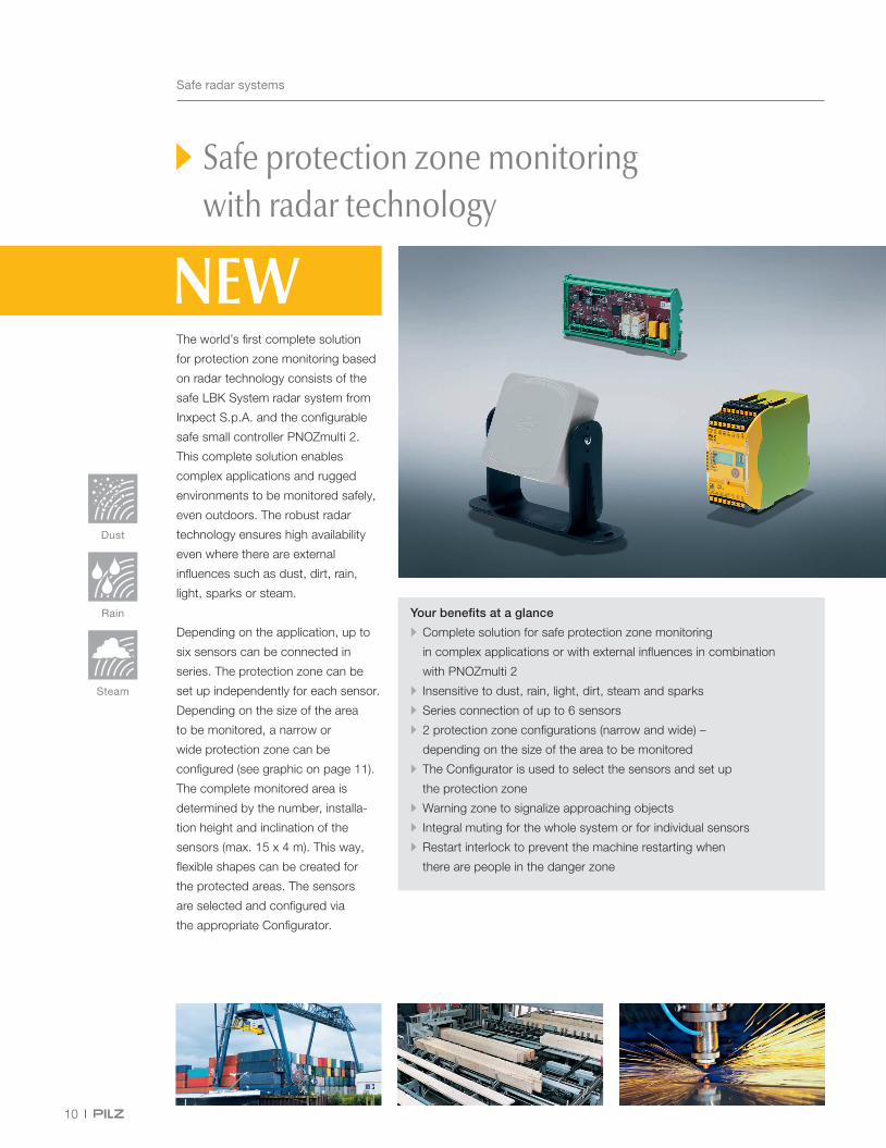
Safe protection zone monitoring with radar technology
The world’s first complete solution
for protection zone monitoring based
on radar technology consists of the
safe LBK System radar system from
Inxpect S.p.A. and the configurable
safe small controller PNOZmulti 2.
This complete solution enables
complex applications and rugged
environments to be monitored safely,
even outdoors. The robust radar
technology ensures high availability
even where there are external
influences such as dust, dirt, rain,
light, sparks or steam.
Depending on the application, up to
six sensors can be connected in
series. The protection zone can be
set up independently for each sensor.
Depending on the size of the area
to be monitored, a narrow or
wide protection zone can be
configured (see graphic on page 11).
The complete monitored area is
determined by the number, installa-
tion height and inclination of the
sensors (max. 15 x 4 m). This way,
flexible shapes can be created for
the protected areas. The sensors
are selected and configured via
the appropriate Configurator.
Rain
Steam
Dust
Your benefits at a glance
• Complete solution for safe protection zone monitoring
in complex applications or with external influences in combination
with PNOZmulti 2
• Insensitive to dust, rain, light, dirt, steam and sparks
• Series connection of up to 6 sensors
• 2 protection zone configurations (narrow and wide) –
depending on the size of the area to be monitored
• The Configurator is used to select the sensors and set up
the protection zone
• Warning zone to signalize approaching objects
• Integral muting for the whole system or for individual sensors
• Restart interlock to prevent the machine restarting when
there are people in the danger zone

4 m110°
50°
4 m30°
15°
LBK-C22-PZ
LBK-S01-PZ
LBK Bus Cable Sensor/Sensor
LBK Bus Terminator
11
Webcode:
web150500
Webcode:
web199925
Safe radar systems
Wide protection zone, opening angle: vertical 30°, horizontal 110°.Narrow protection zone, opening angle: vertical 15°, horizontal 50°.
Side view View from the top
Safe radar system LBK System
Technical features
Type
Common features: • For use in applications up to
- SIL 2 (IEC 61508) - PL d (EN ISO 13849-1) - Category 2
• Working bandwidth frequency: 24 – 24.25 GHz (UK, FR: 24.05 – 24.25 GHz)
• FMCW: frequency modulated continuous wave
Control unit:LBK-C22-PZ • Protection type: IP20 • Connection type: CANopen • Dimensions (H x W x D) in mm: 92.6 x 166.3 x 46.5
Sensor: LBK-S01-PZ • Opening angle: 110° horizontal, 30° vertical • Operating range: 4 m • Connection type: CANopen • Reaction time: max. 100 ms • Protection type: IP67 • Dimensions (H x W x D) in mm: 125 x 165 x 53 • Including mounting bracket for fixing to the machine or to the floor (without screws)
Order number
Z9000022
Z9000023
LBK bus cable sensor/controller • DeviceNet/CANopen, 5-pin, shielded • Connection 1 (sensor): M12, female connector, A-coded, angled 90°
• Connection 2 (control unit): open cable
LBK bus cable sensor/sensor • DeviceNet/CANopen, 5-pin, shielded • Connection 1: M12, female connector, A-coded, angled 90° • Connection 2: M12, male connector, A-coded, angled 90°
LBK bus terminator • M12, 5-pin, male connector, A-coded, straight
5 m Z900002510 m Z900002615 m Z9000027
3 m Z9000028
Z9000024
Online information at www.pilz.com
Further information on the PNOZmulti 2:
Fast and simple configuration with the appropriate Configurator:
Monitoring of danger zones with the LBK System from Inxpect and the configurable safe small controller PNOZmulti 2.

12
Safety relay
Safety relay PNOZsigma – safe voltage monitor PNOZ s60
The voltage monitoring relay is
the successor of PNOZ X PU3Z
and is used for safe monitoring of
de-energized 1- or 3-phase supplies
with neutral conductor. It measures
the voltage at the three phases and
only enables the safety circuit when
the value falls below the threshold
value. If the plant remains energized
after switching off due to a mechanical
malfunction, such as the welding of
contacts on the main switch, the
PNOZ s60 reliably prevents access to
the machine. By monitoring the safe
voltage-free state, maintenance work
on plant and machinery can also be
carried out safely.
Your benefits at a glance
• Meets all the requirements for implementation of SLS applications
(Safety Lockout System)
• Certified safety through UL-6420 approval
• 2 switching thresholds (12 V/6 V) for customized industrial use
• Extended supply voltage range
(24 – 48/100 – 240 VAC/DC)
• Comprehensive diagnostic capability via LEDs reduces downtimes
and supports troubleshooting
• Cabling costs are reduced due to push-in technology and by expanding
the number of contacts through plug-in connectors
• Ability to use contact expansion from the PNOZsigma range
• Narrow width saves space in the control cabinet (90 mm)
PNOZ s60
13
Webcode:
web150099
Safety relay
Safety relay PNOZsigma – safe voltage monitor PNOZ s60
Technical features
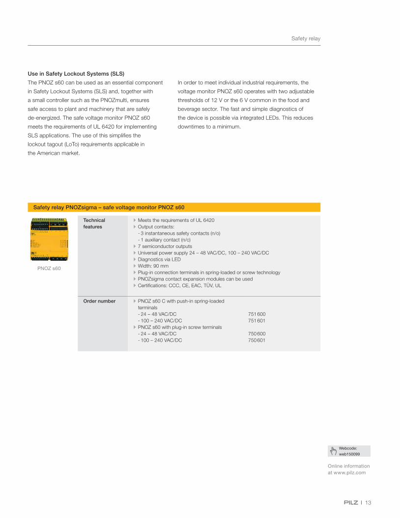
• Meets the requirements of UL 6420 • Output contacts:
- 3 instantaneous safety contacts (n/o) - 1 auxiliary contact (n/c)
• 7 semiconductor outputs • Universal power supply 24 – 48 VAC/DC, 100 – 240 VAC/DC • Diagnostics via LED • Width: 90 mm • Plug-in connection terminals in spring-loaded or screw technology • PNOZsigma contact expansion modules can be used • Certifications: CCC, CE, EAC, TÜV, UL
Order number • PNOZ s60 C with push-in spring-loaded terminals - 24 – 48 VAC/DC - 100 – 240 VAC/DC
• PNOZ s60 with plug-in screw terminals - 24 – 48 VAC/DC - 100 – 240 VAC/DC
751 600751 601
750 600750 601
Use in Safety Lockout Systems (SLS)
The PNOZ s60 can be used as an essential component
in Safety Lockout Systems (SLS) and, together with
a small controller such as the PNOZmulti, ensures
safe access to plant and machinery that are safely
de-energized. The safe voltage monitor PNOZ s60
meets the requirements of UL 6420 for implementing
SLS applications. The use of this simplifies the
lockout tagout (LoTo) requirements applicable in
the American market.
In order to meet individual industrial requirements, the
voltage monitor PNOZ s60 operates with two adjustable
thresholds of 12 V or the 6 V common in the food and
beverage sector. The fast and simple diagnostics of
the device is possible via integrated LEDs. This reduces
downtimes to a minimum.
Online information at www.pilz.com
14
Configurable safe small controllers
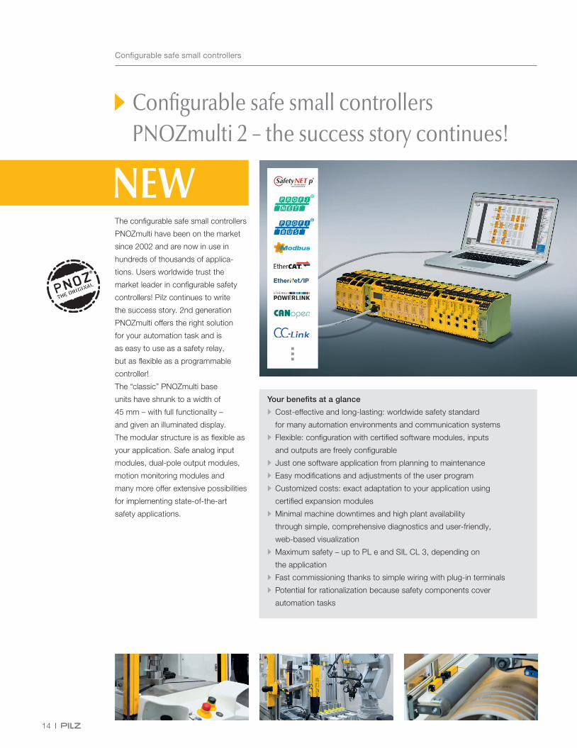
Configurable safe small controllers PNOZmulti 2 – the success story continues!
Your benefits at a glance
• Cost-effective and long-lasting: worldwide safety standard
for many automation environments and communication systems
• Flexible: configuration with certified software modules, inputs
and outputs are freely configurable
• Just one software application from planning to maintenance
• Easy modifications and adjustments of the user program
• Customized costs: exact adaptation to your application using
certified expansion modules
• Minimal machine downtimes and high plant availability
through simple, comprehensive diagnostics and user-friendly,
web-based visualization
• Maximum safety – up to PL e and SIL CL 3, depending on
the application
• Fast commissioning thanks to simple wiring with plug-in terminals
• Potential for rationalization because safety components cover
automation tasks
The configurable safe small controllers
PNOZmulti have been on the market
since 2002 and are now in use in
hundreds of thousands of applica-
tions. Users worldwide trust the
market leader in configurable safety
controllers! Pilz continues to write
the success story. 2nd generation
PNOZmulti offers the right solution
for your automation task and is
as easy to use as a safety relay,
but as flexible as a programmable
controller!
The “classic” PNOZmulti base
units have shrunk to a width of
45 mm – with full functionality –
and given an illuminated display.
The modular structure is as flexible as
your application. Safe analog input
modules, dual-pole output modules,
motion monitoring modules and
many more offer extensive possibilities
for implementing state-of-the-art
safety applications.

15
Webcode:
web150500
Online information at www.pilz.com
Configurable safe small controllers
Modular and flexible
The configurable safe small controllers are suitable
for both simple machines and large automation projects.
In combination with the web-based visualization software
PASvisu, the diagnostics and visualization panels PMIvisu,
the safe sensor technology PSEN, the operator devices
PIT and the decentralized periphery PDP67, you get a
totally compatible, complete solution for your automation
tasks. A wide range of expansion modules such as
analog input modules, dual-pole output modules,
motion monitoring modules, input and output modules
as well as connection modules offer you maximum
flexibility in your application.
Safe and simple
The software tool PNOZmulti Configurator will impress
you with its simple operation: install, open, work intuitively.
Once user programs have been created, they can be
flexibly adapted and reused again and again. A wide range
of diagnostic options ensures short downtimes for your
plant and machinery. All you need is just one software
application from planning to maintenance. As a worldwide
safety standard for numerous automation environments
and communication systems, PNOZmulti 2 also protects
your plant and machinery safely and in compliance with
standards up to PL e/SIL CL 3.
Configurable safe small controllers PNOZmulti 2 – worldwide safety standard
Count on the bestseller and the worldwide safety standard for all machine types. The simple, graphics
configuration tool saves engineering costs because you can create your user program simply and intuitively
on the PC. User-friendly, web-based visualization and simple diagnostics options reduce downtimes.
While others are still wiring, you are already producing – safely!

16
Configurable safe small controllers
Safe small controllers PNOZmulti Configurator – a simple safe drive solution
The PNOZmulti Configurator is a
software tool used to configure the
safe small controllers PNOZmulti.
Software version 10.11 enables
you to use the real-time Ethernet
SafetyNET p RTFL to configure
a secure data exchange between
PNOZmulti 2 base units (PNOZ m B0
or B1) and the safe motion solution
PMCprotego DS. PMCprotego DS
is composed of the servo amplifier
PMCprotego D and the safety card
PMCprotego S3. 32-bit data is
exchanged via RTFL, enabling short
reaction times for your application.
Previously you could connect up to
16 PNOZmulti 2 base units in a linear
topology via the expansion module
PNOZ m EF SafetyNET. Now it is
also possible to incorporate the safe
motion solution PMCprotego DS into
the SafetyNET p network, creating a
safe drive solution in conjunction with
PNOZmulti 2. PNOZmulti 2 monitors
the drive solution and ensures the
movement is stopped in a controlled
and therefore safe manner.
Your benefits at a glance
• Safe and rapid communication via the real-time
Ethernet SafetyNET p RTFL with short reaction times and
easy networking via software tools
• Stable motion monitoring applications through configurable
tolerance times
Another new feature from version 10.11
is selectable tolerance times for
track signals from the PNOZmulti 2
motion monitoring modules
PNOZ m EF 1MM/2MM. A new
encoder type for proximity switches
with reduced diagnostics is also
available, e.g. for use in wind turbines.

PNOZmulti Configurator
17
Configurable safe small controllers
Configurable safe small controllers PNOZmulti – PNOZmulti Configurator, version 10.11
Technical features
• PNOZmulti Configurator: graphical software tool for configuring and programming safe small controllers PNOZmulti
• Configuration of a safe SafetyNET p RTFL network with up to 16 subscribers in linear topology. The network must contain at least 1 PNOZmulti 2 system. Up to 128 virtual inputs and 32 virtual outputs can be defined for each base unit. The safe motion solution PMCprotego DS can now be integrated into the network. The safe virtual inputs and outputs that are defined for the SafetyNET p communication are selected for every SafetyNET p subscriber in the software tool PNOZmulti Configurator or PASmotion in the project.
• Configurable tolerances with motion monitoring modules PNOZ m EF 1MM or 2MM. The tolerance time influences the sensitivity to invalid signal levels (e.g. with EMC disturbances). The greater the configured tolerance time, the less sensitive the system becomes to invalid signal levels.
• New encoder type for proximity switches with reduced diagnostics
Order number • In order to use the full scope of the PNOZmulti Configurator, you will need a valid licence in addition to the software package. Purchasing a licence converts the demo software with restricted functionality to a full version. Information on the available licences can be found at www.pilz.com, webcode: web 151344
• Demo software can be downloaded from the Internet (for registered users), information at www.pilz.com, webcode: web150399
PNOZmulti Configurator, Basic Licence • Full version 773 010B
• PNOZ m B0 772 100 • PNOZ m B1 772 101 Webcode:
web150399
Download of the demo software at www.pilz.com
At least 1 PNOZmulti, max. 15 PMCprotego DS
PNOZ m EF SafetyNET + PNOZ m B1 + PNOZ m EF 4DI4DOR
PNOZ m EF SafetyNET + PNOZ m B0
PMCprotego D + PMCprotego S3
PMI PNOZmulti Configurator/Network Editor + PASmotion
From version 10.11 of the PNOZmulti Configurator: safe communication via the real-time Ethernet SafetyNET p with the safe small controllers PNOZmulti 2 and safe motion solution PMCprotego DS. Watch our What’s New videos to gain an overview of the new functions of version 10.11: www.pilz.com/pnozmulti-configurator-videos

18
Configurable safe small controllers
Safe small controllers PNOZmulti Configurator – access permissions with PITreader
The software tool PNOZmulti
Configurator offers you a new input
element from software version 10.10
with which you can easily configure
access permissions for plant and
machinery. In combination with the
base unit PNOZ m B1 and reading
unit PITreader with RFID technology,
you can implement authentications
and authorizations for plant and
machinery. Users can authenticate
themselves on the PNOZmulti by
inserting a transponder key into the
read area of the PITreader; they will
then be authorized to carry out certain
operations. The permission on the
transponder key must meet the
condition for the required permission
as configured.
The options range from a simple
enable and authentication of specific
machine component functions to
a complex hierarchical permission
matrix. PITreader can be used
flexibly as a stand-alone device or
in conjunction with a controller
from Pilz, in particular the base
unit PNOZ m B1. PITreader and
PNOZmulti 2 thus combine safety
and security functions in one system.
Your benefits at a glance
• PITreader: ability to control access permissions with a high level
of manipulation protection, all staff members are given the machine
enables that match their abilities. Safety and security combined in
one system
• Macro elements: saves costs and time, set macros once and
re-use again and again

PNOZmulti Configurator
19
Webcode:
web150399
Configurable safe small controllers
Configurable safe small controllers PNOZmulti – PNOZmulti Configurator, version 10.10
Technical features
• PNOZmulti Configurator: graphical software tool for configuring and programming safe small controllers PNOZmulti
• Newly connected device PITreader is supported for the base unit PNOZ m B1: users can authenticate themselves on the PNOZmulti by inserting a transponder key into the read area of the PITreader; they will then be authorized to carry out certain operations. Configuration of the required PITreader permissions with the element PITreader authorization
• Macros for PNOZ m B1: the macro function is now also available for base units PNOZ m B1. Macros are also migrated during the migration from base unit PNOZ m B0 to PNOZ m B1.
• LOOP outputs can now be selected as the start input with input elements.
Order number • In order to use the full scope of the PNOZmulti Configurator, you will need a valid licence in addition to the software package. Purchasing a licence converts the demo software with restricted functionality to a full version. Information on the available licences can be found at www.pilz.com, webcode: web 151344
• Demo software can be downloaded from the Internet (for registered users), information at www.pilz.com, webcode: web150399
PNOZmulti Configurator, Basic Licence • Full version 773 010B
• PNOZ m B1 772 101 • PITreader base unit 402 255 • PITreader key adapter h 402 308
Watch our What’s New videos to gain an overview of the new functions of version 10.10: www.pilz.com/pnozmulti-configurator-videos
Download of the demo software at www.pilz.com
Save time and costs with macro elements
From version 10.10, macro elements can be created for
the base unit PNOZ m B1. The logic connections that
are defined between inputs and outputs can be combined
into macro elements. Once created, macro elements are
stored in the macro library. They are then available for use
in all further configurations and save time for subsequent
projects, and the quality remains constant. Any changes
to a macro element in the project are adapted automati-
cally. A simple import and export function and the ability
to edit macros within the editor reduce your engineering
time and save costs. You can implement larger, more
complex projects as the use of macro elements allows
you to reduce connection lines and the projects
become more manageable. You also save time during
diagnostics and troubleshooting, because macro
elements are displayed in powerflow. Diagnostic
information can be mapped. Macros can be read
and write protected, so protecting your expertise.
With the availability of macros for the base unit
PNOZ m B1 it is simple to migrate all your projects
to 2nd generation PNOZmulti devices, supported
by software. So you can benefit from the advantages
of the configurable safe small controllers PNOZmulti 2
and keep effort to a minimum.

20
Configurable safe small controllers
Safe small controllers PNOZmulti Configurator – offline simulation
The software tool PNOZmulti
Configurator will impress you with
its ease of operation. You can use
it for planning, configuration,
documentation and commissioning.
From version 10.9 onwards you can
already test your configured user
program with the Simulation function
before commissioning. With this first
release you can calculate the logic
elements and in further releases
you will be able to calculate all
the elements with Simulation.
Elements that are not simulated
can be switched to the required
state by forcing the outputs so that
a simulation of the overall application
is possible. This allows you to
additionally simulate the user program
only in parts and thus save the
effort of having to define all inputs!
The state of the inputs and outputs
of the configured elements and the
connections between the elements
are displayed. Active inputs, outputs
and connections are highlighted
in color. Elements that can be
simulated are marked accordingly
in the tool.
Your benefits at a glance
• Simulation opens up considerable savings potential in project planning
• Verification of complex logic at the click of a mouse
• Convenient tool for early detection, analysis and rectification of errors
• Simulation helps to reduce risks for human and machine
• Installation costs can be cut

PNOZmulti Configurator
21
Configurable safe small controllers
Configurable safe small controllers PNOZmulti – PNOZmulti Configurator, version 10.9
Technical features
• PNOZmulti Configurator: graphical software tool for configuring safe small controllers PNOZmulti
• Features: - Display of inputs and outputs in variable list: The simulated input and output signals of the elements can be displayed in the variable list. - Forcing inputs and outputs: The state of a signal can be fixed, irrespective of the user program (permanent “1” signal or permanent “0” signal). This so-called forcing can be activated or deactivated for all the outputs. - Simulation is available for logic elements and 2 operating modes: Inching and permanent cycle
Order number • In order to use the full scope of the PNOZmulti Configurator, you will need a valid licence in addition to the software package. Purchasing a licence converts the demo software with restricted functionality to a full version. Information on the available licences can be found at www.pilz.com, webcode: web 151344
• Demo software can be downloaded from the Internet (for registered users), information at www.pilz.com, webcode: web150399
PNOZmulti Configurator, Basic Licence • Full version 773 010B
From PNOZmulti Configurator version 10.9 you can already test your configured user program with the “Simulation” function before commissioning. With the first release you can calculate the logic elements, in further releases you will be able to calculate all the elements with Simulation. The following video describes how to use the Simulation function in practice for your automation projects: www.pilz.com/pnozmulti-configurator-videos
Webcode:
web150399
Download of the demo software at www.pilz.com

22
With the SecurityBridge, certified
by TÜV SÜD in accordance with
IEC 62443-4-1 and IEC 62443-3-3,
the configurable safe small controllers
PNOZmulti and the automation
system PSS 4000 are protected
against manipulation through
unauthorized access on the
control network.
SecurityBridge can be connected
upstream of the base unit of
the PNOZmulti or PLC controller
PSSuniversal PLC. It acts as
a VPN server, via which a virtual
private network (VPN) with one or
more client PCs (configuration PC)
can be established. Only suitably
authorized users can make changes
to a project’s configuration. This
prevents unauthorized access to the
protected network. The result is that
the data transfer between the client
PC and SecurityBridge is protected
against tapping and manipulation.
Your benefits at a glance
• TÜV SÜD-certified and developed in accordance with IEC 62443-4-1
and IEC 62443-3-3
• Protection against manipulation of data through authentication and
authorization management
• Increases plant availability because only required data
(authorized configuration and process data) is transferred
• Forwarding of low-latency process data
• Reveals unauthorized changes to the project by monitoring
the check sum (CRC)
• Prevents unauthorized access because downstream devices are
in a protected network
• Only suitably authorized users can make changes
to a project’s configuration.
SecurityBridge protects Pilz controllers
Networks

PCOM sec br1
23
Webcode:
web188268
SecurityBridge
Networks
Technical features
• Web-based user interface for easy configuration, diagnostics and maintenance • Connection with the central authentication system via RADIUS • Continuous updates independent of the control system • Integrated digital inputs and outputs, e.g. to activate the VPN tunnel • VPN server to establish a VPN tunnel for secure data transfer • USB interface for backing up and restoring the configuration on USB memory
• LED display for error messages and diagnostics
Order number • PCOM sec br1 Module for safe authentication and communication with PNOZmulti
• PCOM sec br2 Module for safe authentication and communication with PNOZmulti and the controllers PSSuniversal PLC and PSSuniversal multi
• 1 set of spring-loaded terminals • 1 set of screw terminals
311 501
311 502
751 016750 016
The SecurityBridge prevents unauthorized access to its downstream devices.
Online information at www.pilz.com

24
Remote I/O system
New electronic modules with
analog inputs and outputs for
voltage and current signals are
available for the remote I/O system
PSSuniversal 2. An additional
electronic module with six digital
inputs for 120 volt AC signals enables
the use with other mains voltage,
e.g. such as is found on the
American market.
All electronic modules can be
used independently of the control
network and protocol used. You
can either connect them to the
head module using EtherNet/IP or
with PROFINET. Because the
backplane is used for communication
between the head module and the
electronic modules, you can exchange
or reconfigure electronic modules
during operation without having to
switch off the overall structure. This
reduces the downtimes for your plant!
It is therefore ideal for the automation
of your plants.
Your benefits at a glance
• Easy and flexible in commissioning and service thanks to
the three-part system structure
• Change of the electronic modules during operation (hot swapping)
possible
• Any required design combining safety-related and
non-safety-related modules possible
• Rapid fault localization and troubleshooting thanks to the LED display
of the faulty module slot and the affected terminal
• Adaptation to PROFINET, Ethernet/IP and other protocols
by selecting the corresponding head module
• Analog inputs with configurable filter, range and threshold
monitoring, monitoring in accordance with Namur NE43 and
scalable measurements
• Configuration via engineering tool PASconfig
Winner of the iF DESIGN AWARD 2017
Extended application range for the remote I/O system PSSuniversal 2

PSS u2 ES 4AI U
PSS u2 ES 4AI I
PSS u2 ES 6DI 120V AC
25
Webcode:
web180627
Remote I/O system
Remote I/O system PSSuniversal 2 – new electronic modules
Online information at www.pilz.com
Further modules and accessories can be found in the E-Shop under:
Technical features
Type
Electronic module PSS u2 ES 4AI UStandard electronic module for recording analog signals • 4 analog inputs for voltage measurement • Each input can be configured separately • Resolution: 16 Bit • Measuring ranges [12]: -12.8 V to +12.8 V, -6.4 V to +6.4 V, -3.2 V to +3.2 V
• Configurable filters • 4 range and 8 threshold monitors per input • Two's complement or sign and magnitude representation • Monitoring in accordance with Namur NE43 can be activated • Measurement scalable • Energy-saving functions
Order number
328 500
Electronic module PSS u2 ES 4AI IStandard electronic module for recording analog signals • 4 analog inputs for current measurement • Each input can be configured separately • Resolution: 15 Bit • Current limitation per input • Measuring range [12] 0 to 25.6 mA • Configurable filters • 4 range and 8 threshold monitors per input • Two's complement or sign and magnitude representation • Monitoring in accordance with Namur NE43 can be activated • Measurement scalable • Energy-saving functions
328 520
Electronic module PSS u2 ES 4AO U/IStandard electronic module for current and voltage signals • 4 analog outputs for current and voltage measurement • Resolution: 16 Bit • Voltage ranges: -12 to +12 V, 0 to +10 V • Current ranges: -24 to +24 mA, 0 to +20 mA
328 551
Electronic module PSS u2 ES 6DI 120V ACStandard electronic module for recording digital signals • 6 digital inputs 120 V AC of Type 1 and Type 3 in accordance with IEC 61131-2
• Configurable input filter time: 5 to 25.5 [ms] • Configurable pulse stretching: 0 to 255 [ms] • Energy-saving function
328 308
Head module PSS u2 P0 F/S PNHead module PROFINET Client, PROFIsafe Device, integrated Ethernet switch (two Ethernet ports), configurable with PASconfig tool, PSS u2 backboard bus for connection of up to 64 I/O modules
328 061
Head module PSS u2 P0 F/S EIPHead module EtherNet/IP Client/CIP Safety Device, integrated Ethernet Switch (two Ethernet ports), configurable with PASconfig tool, PSS u2 backboard bus for connection of up to 64 I/O modules
328 071

26
Remote I/O system
Automated parameterization and extended diagnostics thanks to IO-Link master
A module with IO-Link master
is now available for the remote
I/O system PSSuniversal 2 which
can be integrated into PROFINET
and EtherNet/IP networks using
appropriate head modules. The
module provides four IO-Link ports
to which you can connect IO-Link
devices (sensors or actuators).
This means that the remote
I/O system PSSuniversal 2 can now
also communicate with sensors
and actuators via the globally
standardized IO-Link interface
(IEC 61131-9). The configuration
of the IO-Link devices can be
stored in the IO-Link master and
simply transferred when exchanging
during service. This saves time
and reduces errors and plant
downtimes!
Your benefits at a glance
• Configuration stored in the master can be easily written to
the new device during replacement
• Enhanced safety thanks to error-free parameter setting of sensors
• Automated parameterization of the sensors in the event of fault
or service
• Extended diagnostics through communication with
the IO-Link devices also enables open circuit detection
• IO-Link module can be exchanged during operation
• Operators do not have to deal with the parameterization of sensors
• Central documentation of the parameter sets
• Simple configuration of the module using PASconfig software
The PSSuniversal 2 has
won the iF DESIGN AWARD 2017,
so joining the prizewinners
of this internationally renowned
design label.

PSS u2 P0 F/S PN
PSS u2 ES 4IOL
27
Webcode:
web180630
Remote I/O system
Remote I/O system PSSuniversal 2 – IO Link master
Online information at www.pilz.com
Order the IO-Link master module in the E-Shop here:
Technical features
• 4 IO-Link ports for connecting IO-Link devices (sensors or actuators) • Hot swap – module exchange possible during operation • Graphics configuration tool PASconfig with export function for direct import into RSLogix
• GSDML file for configuration in a PROFINET-capable controller • *.I5x file for configuration in an EtherNet/IP-capable controller • Simple IO mapping • Storage of the device configuration in the master • Module consists of: electronic module, terminal block with cage clamp terminals and backplane
Order number • PSS u2 ES 4IOL Standard electronic module for connection of IO-Link devices
Head modules: • PSS u2 P0 F/S EIP Head module EtherNet/IP Client/CIP Safety Device
• PSS u2 P0 F/S PN Head module PROFINET Client/PROFIsafe Device
328 770
328 071
328 061
Configuration of sensors with the IO-Link master module in the configuration tool PASconfig.
Webcode:
web180627
Further modules and accessories can be found on our website under:
28
Operating mode selection and access permission system
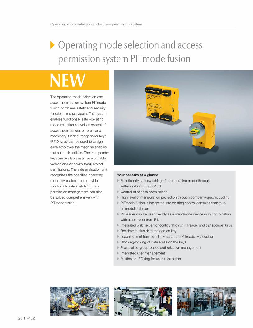
Operating mode selection and access permission system PITmode fusion
The operating mode selection and
access permission system PITmode
fusion combines safety and security
functions in one system. The system
enables functionally safe operating
mode selection as well as control of
access permissions on plant and
machinery. Coded transponder keys
(RFID keys) can be used to assign
each employee the machine enables
that suit their abilities. The transponder
keys are available in a freely writable
version and also with fixed, stored
permissions. The safe evaluation unit
recognizes the specified operating
mode, evaluates it and provides
functionally safe switching. Safe
permission management can also
be solved comprehensively with
PITmode fusion.
Your benefits at a glance
• Functionally safe switching of the operating mode through
self-monitoring up to PL d
• Control of access permissions
• High level of manipulation protection through company-specific coding
• PITmode fusion is integrated into existing control consoles thanks to
its modular design
• PITreader can be used flexibly as a standalone device or in combination
with a controller from Pilz
• Integrated web server for configuration of PITreader and transponder keys
• Read/write plus data storage on key
• Teaching in of transponder keys on the PITreader via coding
• Blocking/locking of data areas on the keys
• Preinstalled group-based authorization management
• Integrated user management
• Multicolor LED ring for user information
PITreader base unit
PIT m4SEU
PITreader key adapter h
29
Webcode:
web150439
Operating mode selection and access permission system
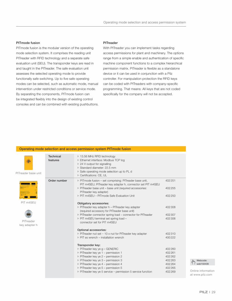
PITmode fusion
PITmode fusion is the modular version of the operating
mode selection system. It comprises the reading unit
PITreader with RFID technology and a separate safe
evaluation unit (SEU). The transponder keys are read in
and taught in the PITreader. The safe evaluation unit
assesses the selected operating mode to provide
functionally safe switching. Up to five safe operating
modes can be selected, such as automatic mode, manual
intervention under restricted conditions or service mode.
By separating the components, PITmode fusion can
be integrated flexibly into the design of existing control
consoles and can be combined with existing pushbuttons.
PITreader
With PITreader you can implement tasks regarding
access permissions for plant and machinery. The options
range from a simple enable and authentication of specific
machine component functions to a complex hierarchical
permission matrix. PITreader is flexible as a standalone
device or it can be used in conjunction with a Pilz
controller. For manipulation protection the RFID keys
can be coded with PITreaders with company-specific
programming. That means: All keys that are not coded
specifically for the company will not be accepted.
Operating mode selection and access permission system PITmode fusion
Technical features
• 13.56 MHz RFID technology • Ethernet interface: Modbus TCP log • 24 V output for signalling • Standard diameter: 22.5 mm • Safe operating mode selection up to PL d • Certifications: CE, UL
Order number • PITmode fusion – set comprising: PITreader base unit, PIT m4SEU, PITreader key adapter h, connector set PIT m4SEU
• PITreader base unit – base unit (required accessories: PITreader key adapter)
• PIT m4SEU – PITmode Safe Evaluation Unit
Obligatory accessories: • PITreader key adapter h – PITreader key adapter (required accessory for PITreader base unit)
• PITreader connector spring load – connector for PITreader • PIT m4SEU terminal set spring load – connector set for PIT m4SEU
Optional accessories: • PITreader nut set – 10 x nut for PITreader key adapter • PIT es wrench – installation wrench
Transponder key: • PITreader key ye g – GENERIC • PITreader key ye 1 – permission 1 • PITreader key ye 2 – permission 2 • PITreader key ye 3 – permission 3 • PITreader key ye 4 – permission 4 • PITreader key ye 5 – permission 5 • PITreader key ye 5 service – permission 5 service function
402 251
402 255
402 250
402 308
402 307402 306
402 310400 222
402 260402 261402 262402 263402 264402 265402 269 Online information
at www.pilz.com

30
Services: Consulting, engineering and training
Pilz Servicesfor Safety and Automation
TrainingInternational qualification program and certified courses
Machinery safety Workplace safetyInternational compliance
Safety through the whole machine lifecycle
Absolute safety when operating machines
Conformity with international standards and regulations
Safe machinery at any stage
Compliant machines worldwide
The maximum possible safety for man and machine
Enhancement of professional development
• Risk Assessment
• Safety Concept
• Safety Design
• System Implementation
• Validation
• CE Marking
• USA
• NR-12
• Plant Assessment
• Lockout Tagout System
• Inspection of Safeguarding Devices
Pilz Services
As a solution supplier, Pilz can help you in the global application of optimum safety strategies that comply with specifications. Our services ensure the highest safety for man and machine worldwide.

31
International compliance
CE Marking
We control all activities and processes for
the necessary conformity assessment procedure,
including the technical documentation that is required.
USA
With us you‘ll receive all the necessary documents that
are required to have your machine certified through local
authorities to achieve US compliance.
NR-12
As a complete supplier we can provide support from
risk assessment to validation, technical documentation
at the manufacturer’s and final acceptance at the
operator’s in Brazil.
Workplace safety
Plant Assessment
We will prepare an overview of your entire plant in
the shortest possible time. With an on-site inspection
we will expose risks and calculate the cost of optimizing
your safeguards.
Lockout Tagout System
Our customized lockout tagout (LoTo) measures guarantee
that staff can safely control potentially hazardous energies
during maintenance and repair.
Inspection of Safeguarding Devices
With our independent, ISO 17020-compliant inspection
body, which is accredited by the German Accreditation
Body (DAkkS), we can guarantee objectivity and high
availability of your machines.
Pilz GmbH & Co. KG, Ostfildern, operates an inspection body for plant and machinery, accredited by DAkkS.
Training
Pilz supports you with a comprehensive range
of training courses on all topics of machinery safety
and automation.
Machinery safety
Risk Assessment
We review your machinery in accordance with
the applicable standards and directives and assess
the existing hazards.
Safety Concept
We develop detailed technical solutions for the safety
of your plant and machinery through mechanical,
electronic and organizational measures.
Safety Design
The aim of the safety design is to reduce or
eliminate danger points through detailed planning
of the necessary protective measures.
System Implementation
The results of the risk analysis and safety design
are implemented to suit the particular requirements
through selected safety measures.
Validation
In the validation, the risk assessment and safety
concept are mirrored and inspected by competent,
specialist staff.
We can also perform collision measurement
for human-robot applications in accordance with
the limit values from ISO/TS 15066.
Services – Portfolio

SupportTechnical support is available from Pilz round the clock.
Americas
Brazil
+55 11 97569-2804
Canada
+1 888 315 7459
Mexico
+52 55 5572 1300
USA (toll-free)
+1 877-PILZUSA (745-9872)
Asia
China
+86 21 60880878-216
Japan
+81 45 471-2281
South Korea
+82 31 778 3300
Australia and Oceania
Australia
+61 3 95600621
New Zealand
+64 9 6345350
Europe
Austria
+43 1 7986263-0
Belgium, Luxembourg
+32 9 3217570
France
+33 3 88104003
Germany
+49 711 3409-444
Ireland
+353 21 4804983
Italy, Malta
+39 0362 1826711
Scandinavia
+45 74436332
Spain
+34 938497433
Switzerland
+41 62 88979-32
The Netherlands
+31 347 320477
Turkey
+90 216 5775552
United Kingdom
+44 1536 462203
You can reach our
international hotline on:
+49 711 3409-444
Presented by:
CEC
E®, C
HR
E®, C
MS
E®, I
ndur
aNET
p®, L
eans
afe®
, Mas
ter
of S
afet
y®, M
aste
r of
Sec
urity
®, P
AS
4000
®, P
AS
cal®
, PA
Sco
nfig®
, Pilz
®, P
IT®, P
LID
®, P
MC
prim
o®, P
MC
prot
ego®
, PM
Cte
ndo®
, P
MD
®, P
MI®
, PN
OZ®
, PR
BT®
, PR
CM
®, P
rimo®
, PR
TM®, P
SEN
®, P
SS
®, P
VIS
®, S
afet
yBU
S p
®, S
afet
yEY
E®, S
afet
yNET
p®, T
HE
SP
IRIT
OF
SA
FETY
® a
re re
gist
ered
and
pro
tect
ed tr
adem
arks
of
Pilz
Gm
bH &
Co.
KG
in s
ome
coun
trie
s. W
e w
ould
poi
nt o
ut th
at p
rodu
ct fe
atur
es m
ay v
ary
from
the
deta
ils s
tate
d in
this
doc
umen
t, de
pend
ing
on th
e st
atus
at t
he ti
me
of p
ublic
atio
n
and
the
scop
e of
the
equi
pmen
t. W
e ac
cept
no
resp
onsi
bilit
y fo
r th
e va
lidity
, acc
urac
y an
d en
tiret
y of
the
text
and
gra
phic
s pr
esen
ted
in th
is in
form
atio
n.
Ple
ase
cont
act o
ur T
echn
ical
Sup
port
if y
ou h
ave
any
ques
tions
.
Pilz develops environmentally-friendly products using
ecological materials and energy-saving technologies.
Offices and production facilities are ecologically designed,
environmentally-aware and energy-saving. So Pilz offers
sustainability, plus the security of using energy-efficient
products and environmentally-friendly solutions.
In many countries we are represented by sales partners. Please refer to our homepage www.pilz.com for further details or contact our headquarters.
Printed on 100 % recycled paper for the good of the environment.
7-8-
us-3
-022
, 202
0-03
© P
ilz G
mbH
& C
o. K
G, 2
020


