
What is “Leveling”
• Levelling is the process by which differences in height between two or more points can be determined. Its purpose may be to provide heights or contours on a plan, to provide data for road cross-sections or volumes of earthworks, or to provide a level or inclined surface in the setting out of construction works

MeanSea Level(MSL)

Definitions
• Datum - This is an arbitrary level surface to which the heights of all points are referred. This may be the National Datum (Australian Height Datum) or local datum point established on a construction site.

MeanSea Level(MSL)
In This Case MeanSea Level is TheDATUM

MeanSea Level(MSL)
In this case the DATUM is lidof Pit

Mean Sea Level(MSL)
• Mean sea level (MSL) is the average (mean) height of the sea between High and Low tides
Definitions
• Reduced Level (RL) – A distance recorded as a Height Above or Below the DATUM. This height is in metres
MeanSea Level(MSL)
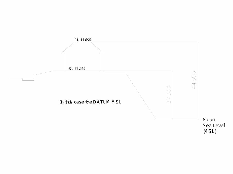
In this case the DATUM MSL
RL 27.969
RL 44.695
MeanSea Level(MSL)
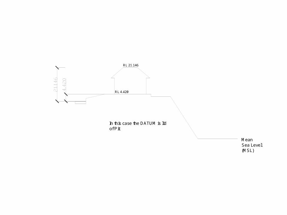
In this case the DATUM is lidof Pit
RL 4.420
RL 21.146

MeanSea Level(MSL)
In this case the DATUM isMean Sea Level
RL 27.969
RL 44.695
MeanSea Level(MSL)
In this case the DATUM is lidof Pit
RL 4.420
RL 21.146

Definitions• A benchmark in every-day language is a point
of reference for a measurement. In surveying a benchmark is specifically any permanent marker placed by a surveyor with a precisely known vertical elevation (but not necessarily a precisely known horizontal location). Designed to be used for many projects.
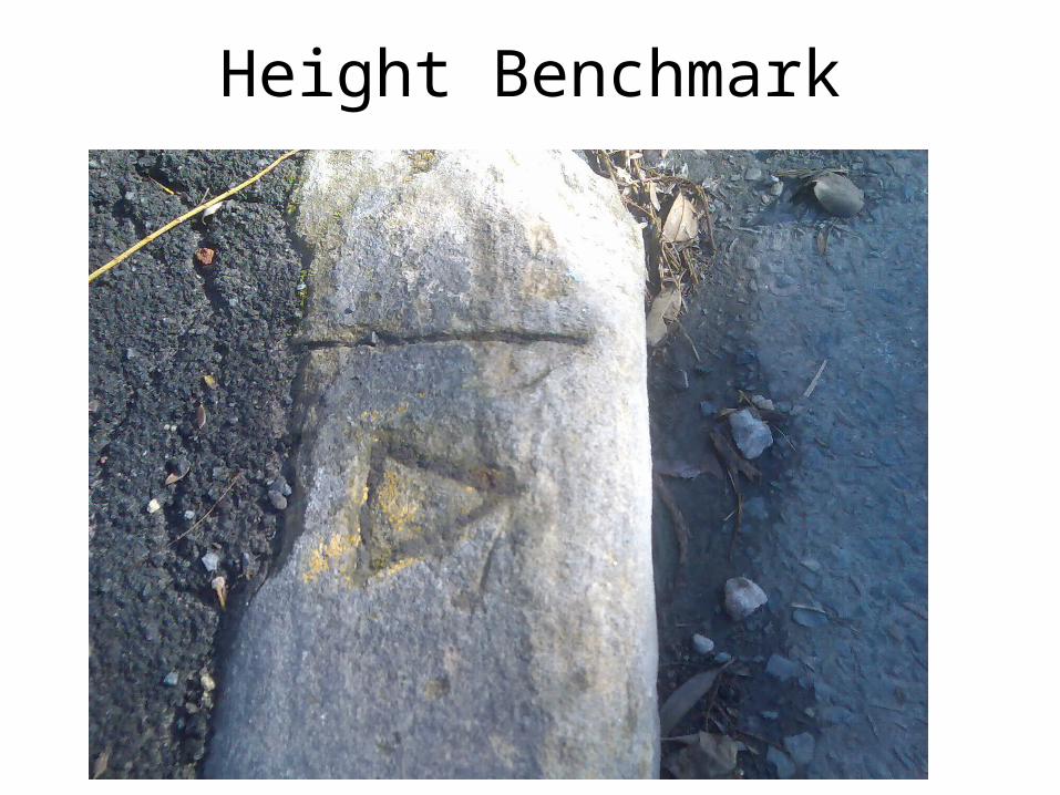
Height Benchmark

Other Types of Bench Marks
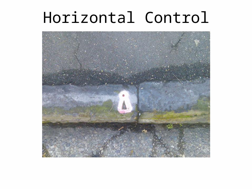
Horizontal Control
MeanSea Level(MSL)
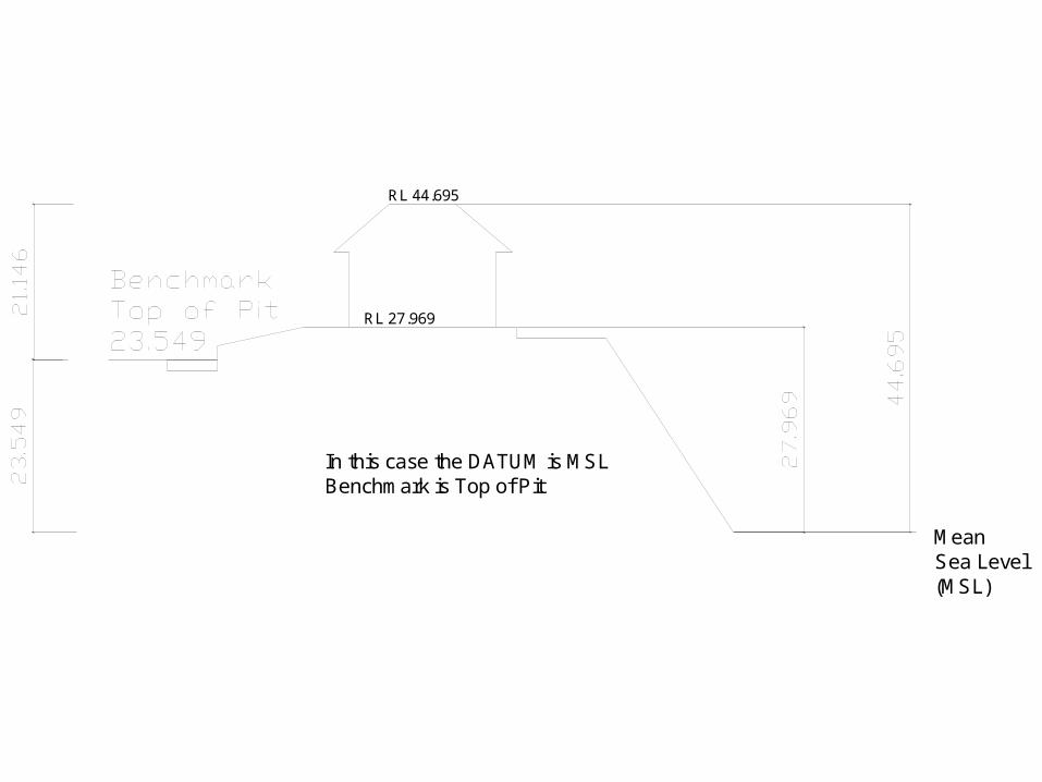
In this case the DATUM is MSLBenchmark is Top of Pit
RL 27.969
RL 44.695

Definitions• A Temporary benchmark (TBM)
Benchmark usually placed for a particular project. Not designed to be a reference for other projects or for long term use

Australian Height Datum (AHD)• The Australian Height Datum is a theoretical
reference surface (datum) for altitude measurement in Australia.
• In 1971 the mean sea level for 1966-1968 was assigned the value of zero on the Australian Height Datum at thirty tide gauges around the coast of the Australian continent.
• The resulting datum surface, has been termed the Australian Height Datum (AHD) and was adopted as the datum to which all vertical control for mapping (and other surveying functions) is to be referred.


MeanSea Level(MSL)
In this case the DATUM is MSLBenchmark is Top of Pit
RL 27.969
RL 44.695

Tools For Leveling
• Spirit Level - or bubble level is an instrument designed to indicate whether a surface is level or plumb
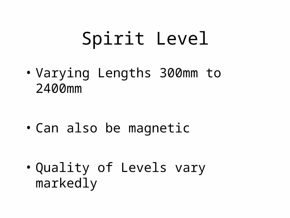
Spirit Level
• Varying Lengths 300mm to 2400mm
• Can also be magnetic
• Quality of Levels vary markedly

Non Magnetic Magnetic
Masonry Digital Levels
Torpedoes

Tools For Leveling
• A line level is a level designed to hang on a builders string line. The body of the level incorporates small hooks to allow it to attach and hang from the string line. The body is lightweight, so as not to weigh down the string line, it is also small in size as the string line in effect becomes the body; when the level is hung in the centre of the string, each leg of the string line extends the levels plane

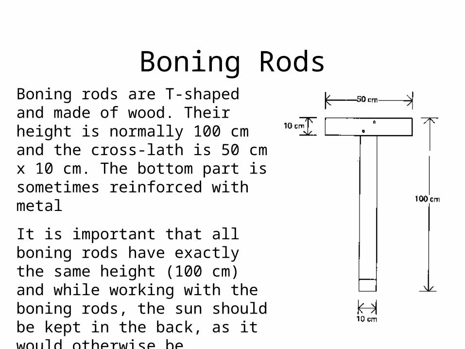
Boning RodsBoning rods are T-shaped and made of wood. Their height is normally 100 cm and the cross-lath is 50 cm x 10 cm. The bottom part is sometimes reinforced with metal
It is important that all boning rods have exactly the same height (100 cm) and while working with the boning rods, the sun should be kept in the back, as it would otherwise be difficult to see them. Usually a total of 3 or 4 boning rods is required.

Boning Rods
Water Level
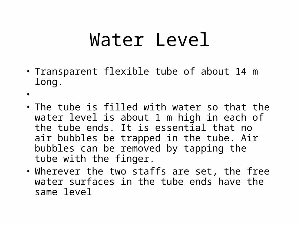
• Transparent flexible tube of about 14 m long. • • The tube is filled with water so that the water
level is about 1 m high in each of the tube ends. It is essential that no air bubbles be trapped in the tube. Air bubbles can be removed by tapping the tube with the finger.
• Wherever the two staffs are set, the free water surfaces in the tube ends have the same level

Water Level

Transit Levels
•Very Accurate
•Very Difficult to Set Up
•Can also set grades
•Works similar to a plumbers pipe level

Definition• Line of
Collimation – Imaginary line that passes through leveling instrument at Cross Hairs

Automatic Level
• The Automatic Level is an easy to use surveying Instrument
• Instrument needs only to be setup level within its circular level bubble
• Has a damping compensator which adjsuts line of colimation
• Generally accurate to +/- 2mm

Automatic Level1. Base Plate
2. Horizontal Circle
3. Eyepiece
4. Circular Bubble
5. Sighting Pointer
6. Objective Lens
7. Focusing Knob
8. Fine Motion Drive
9. Footscrew
10. Bubble Mirror

The Compensator
• Prism suspended by wires • Prism moves to keep line of collimation
level within its design (+/-) 2mm etc
• Prism is magnetically dampened• Suspended Prism may go out adjustment
Laser Level
• Has a compensator similar to Automatic Level
• Radiates a Laser Beam 360 through line of collimation
• Laser is then picked by a receiver to indicate line of collimation
• Some lasers are self leveling

Errors particular to Lasers
• Reflections from other glass objects ie car windscreens
• Rotating Beacons
• Lasers being used at other sites, typically lasers have range of 300m

Definition
• Backsight – A sight taken to a benchmark or temporary benchmark.
• Typically the first sight taken after setting the instrument up

Definition
• Foresight – This the last sight taken before the instrument is moved during a traverse

Definition
• Intermediate Site – These are the sights taken at nominated position, known as stations. The sights are then converted to reduced levels

Leveling Errors
• There are a large number of potential sources of errors in leveling. Many of these are only significant for precise leveling over long distances. For the short segments of leveling that will occur in connecting a TGBM to nearby benchmarks there are only four worth mentioning:
Collimation Error Error due to Earth Curvature Error due to Parallax Error Error due to Refraction

Collimation Error
• The Automatic Prism compensator goes out of alignment.
• The level provides readings outside of its specification

Collimation Error

Parallax Error
• When using an optical instrument — both the image and cross hairs can be focused- if either is imprecisely focused, the cross hairs will appear to move with respect to the object focused, if one moves one's head horizontally in front of the eyepiece.

Parallax Error
Correction of Parallax Error
1. Adjust Focus of lens to infinity
2. Focus of Cross Hairs to a sharp setting Note every users parallax focus is different
3. Refocus on Target and check for parallax
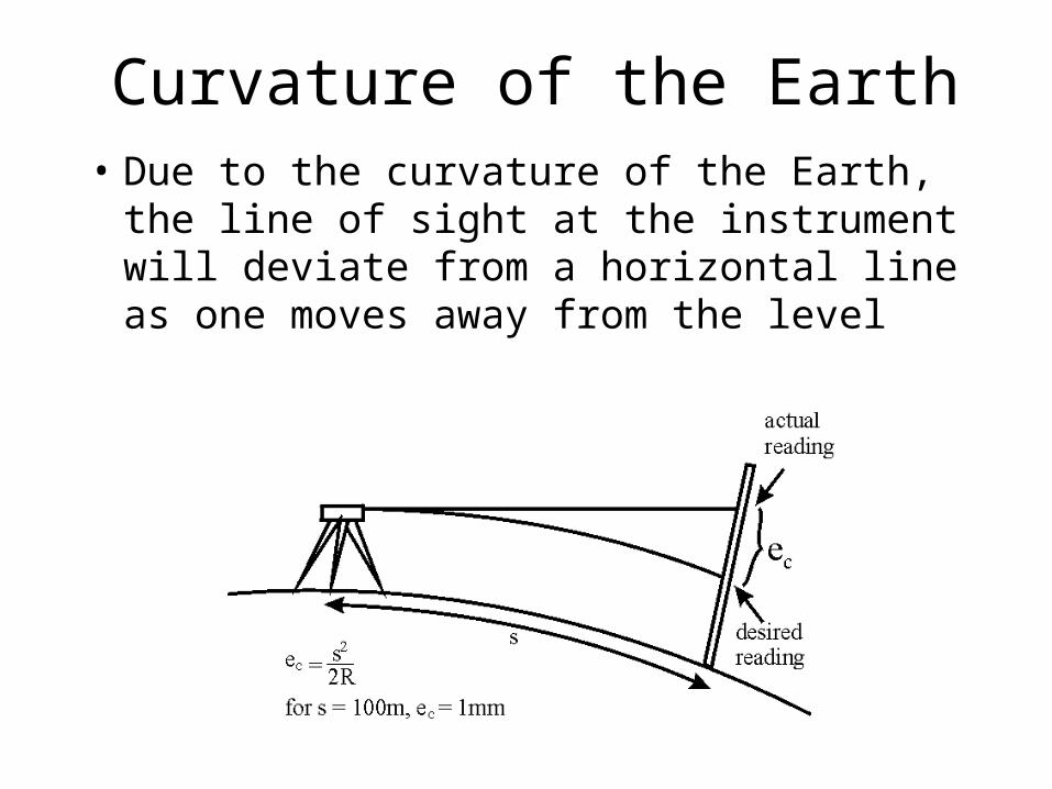
Curvature of the Earth• Due to the curvature of the Earth, the line of
sight at the instrument will deviate from a horizontal line as one moves away from the level

Correction of Curvature Error
• For a sight length of 100m the effect is only 1mm.
• Keep Sight lengths under 50m
• the effect is eliminated by using equal sight lengths for fore- and backsights.
Refraction
• The variable density of the Earth's atmosphere causes a bending of the ray from the staff to the level.
• May also be caused by heat emitted by plant
• May be caused by heat haze
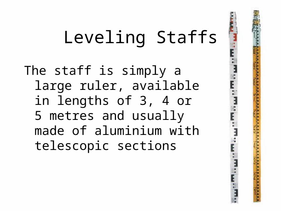
Leveling Staffs
The staff is simply a large ruler, available in lengths of 3, 4 or 5 metres and usually made of aluminium with telescopic sections
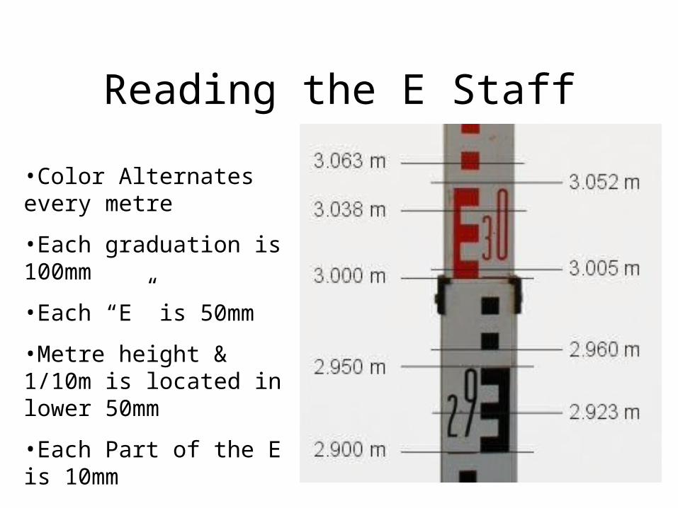
Reading the E Staff
•Color Alternates every metre
•Each graduation is 100mm
•Each “E” is 50mm
•Metre height & 1/10m is located in lower 50mm
•Each Part of the E is 10mm
•Millimeters are interpolated
•Staff is read to the millimeter

Reading an “E-face” staff
0.3
0.33
0.339

Staff Reading Excercise
• Staff Leveling Tutorial
• On Line Excercises found at http://www.sli.unimelb.edu.au/planesurvey/prot/equip/equip1-2-4.html

Reading Staffs
•It is important to hold staff plumb
•Use slow rocking technique
•Use vertical line in level to keep plumb

Step 1 Staff Slowly Leant Towards Instrument
Important Note – The person using the instrument keeps the staff vertical by use of the Vertical line in the instrument.
Step 2 Staff Slowly Tilted away from Instrument. When Vertical lowest reading will be reading recorded
Step 3 Staff Slowly Tilted away from instrument. Once past vertical readings will increase
Removing Staff Reading Errors

Stadia Reduction
• The middle line is the line of Collimation
• The Short lines are called stadia lines
• Usually Stadia multiplier is 100

Stadia Reduction
• Upper stadia = 3.040 • Lower stadia = 2.946• Stadia difference = 0.094
• Distance to staff = 0.094 x 100 = 9.4 metres
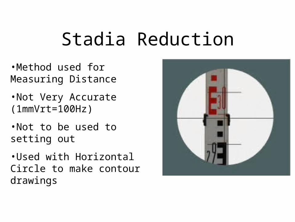
Stadia Reduction•Method used for Measuring Distance
•Not Very Accurate (1mmVrt=100Hz)
•Not to be used to setting out
•Used with Horizontal Circle to make contour drawings

Definition - Traverse• A method of transferring a benchmark• Can be Open or Closed
– Open Traverse begins at a point of known position and ends at a station whose position is unknown (This traverse type should be avoided)
– Closed Traverse begins and ends at the same point whose position is known.

Schematic of a Traverse
B/S 2.510F/S 1.202Diff Between 1.308
B/S 2.301F/S 1.517Diff Between 0.784

Traversing Exercise

Step 1
Set up the instrument where the benchmark can be viewed within correct parameters and a reasonable number of sights can be viewed. This location is identified as L1 circled in red

Step 2
Surveyor______________________ Chainmen_________________________________
Instrument No___________________ Date__________________
BacksightIntermediate
Sight Foresight Rise FallReduced
Level Top Bottom Dist Remarks1.575 47.195 1.817 1.377 44.000 BM
Booking Sheet

Step 3
Surveyor______________________ Chainmen_________________________________
Instrument No___________________ Date__________________
BacksightIntermediate
Sight Foresight Rise FallReduced
Level Top Bottom Dist Remarks1.575 47.195 1.817 1.377 44.000 BM
1.250 Station 10.850 Station 21.330 Station 31.580 Station 4
Booking Sheet

Step 4
Surveyor______________________ Chainmen_________________________________
Instrument No___________________ Date__________________
BacksightIntermediate
Sight Foresight Rise FallReduced
Level Top Bottom Dist Remarks1.575 47.195 1.817 1.377 44.000 BM
1.250 Station 10.850 Station 21.330 Station 31.580 Station 4
1.450 1.462 1.438 24.000 S5 (CP)
Booking Sheet
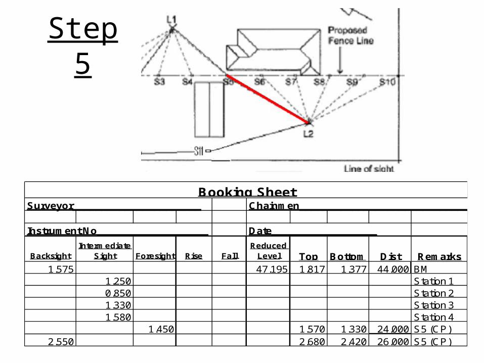
Step 5
Surveyor______________________ Chainmen_________________________________
Instrument No___________________ Date__________________
BacksightIntermediate
Sight Foresight Rise FallReduced
Level Top Bottom Dist Remarks1.575 47.195 1.817 1.377 44.000 BM
1.250 Station 10.850 Station 21.330 Station 31.580 Station 4
1.450 1.570 1.330 24.000 S5 (CP)2.550 2.680 2.420 26.000 S5 (CP)
Booking Sheet

Step 6
Surveyor______________________ Chainmen_________________________________
Instrument No___________________ Date__________________
BacksightIntermediate
Sight Foresight Rise FallReduced
Level Top Bottom Dist Remarks1.575 47.195 1.597 1.553 44.000 BM
1.250 S10.850 S21.330 S31.580 S4
1.450 1.570 1.330 24.000 S5 (CP)2.550 2.680 2.420 26.000 S5 (CP)
1.980 S61.760 S71.710 S81.840 S91.920 S10
Booking Sheet

Step 7
Surveyor______________________ Chainmen_________________________________
Instrument No___________________ Date__________________
BacksightIntermediate
Sight Foresight Rise FallReduced
Level Top Bottom Dist Remarks1.575 47.195 1.597 1.553 44.000 BM
1.250 S10.850 S21.330 S31.580 S4
1.450 1.570 1.330 24.000 S5 (CP)2.550 2.680 2.420 26.000 S5 (CP)
1.980 S61.760 S71.710 S81.840 S91.920 S10
3.250 S11 (CP)
Booking Sheet

Step 8
Surveyor______________________ Chainmen_________________________________
Instrument No___________________ Date__________________
BacksightIntermediate
Sight Foresight Rise FallReduced
Level Top Bottom Dist Remarks1.575 47.195 1.597 1.553 44.000 BM
1.250 S10.850 S21.330 S31.580 S4
1.450 1.570 1.330 24.000 S5 (CP)2.550 2.680 2.420 26.000 S5 (CP)
1.980 S61.760 S71.710 S81.840 S91.920 S10
3.250 3.400 3.100 30.000 S11 (CP)1.831 2.021 1.641 38.000 S11 (CP)
1.258 1.418 1.098 32.000 BM
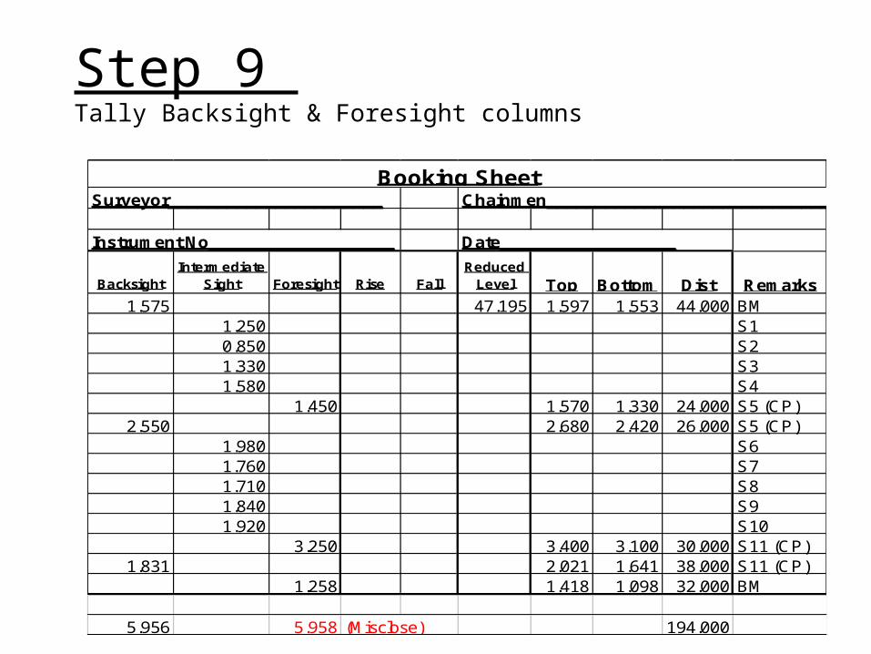
Step 9 Tally Backsight & Foresight columns
Surveyor______________________ Chainmen_________________________________
Instrument No___________________ Date__________________
BacksightIntermediate
Sight Foresight Rise FallReduced
Level Top Bottom Dist Remarks1.575 47.195 1.597 1.553 44.000 BM
1.250 S10.850 S21.330 S31.580 S4
1.450 1.570 1.330 24.000 S5 (CP)2.550 2.680 2.420 26.000 S5 (CP)
1.980 S61.760 S71.710 S81.840 S91.920 S10
3.250 3.400 3.100 30.000 S11 (CP)1.831 2.021 1.641 38.000 S11 (CP)
1.258 1.418 1.098 32.000 BM
5.956 5.958 (Misclose) 194.000
Booking Sheet

Definition - Misclose
• Definition – Misclose- is when closing of a traverse due to errors in readings and instrument limitations there is a discrepancy.
• The allowable discrepancy is (12 x square root of traverse in kilometres)

Traverse Misclose
• Traverse Length = 190 metres
• Allowable Misclose = 12 x SQRT(0.190)= 12 x 0.4359= 5.23mm

Step 10a Calculate Rise & Falls
Surveyor______________________ Chainmen_________________________________
Instrument No___________________ Date__________________
BacksightIntermediate
Sight Foresight Rise FallReduced
Level Top Bottom Dist Remarks1.575 47.195 1.597 1.553 44.000 BM
1.250 0.325 S10.850 0.400 S21.330 -0.480 S31.580 -0.250 S4
1.450 0.130 1.570 1.330 24.000 S5 (CP)2.550 2.680 2.420 26.000 S5 (CP)
1.980 0.570 S61.760 0.220 S71.710 0.050 S81.840 -0.130 S91.920 -0.080 S10
3.250 -1.330 3.400 3.100 30.000 S11 (CP)1.831 2.021 1.641 38.000 S11 (CP)
1.258 0.573 1.418 1.098 32.000 BM
5.956 5.958 194.000
Booking Sheet
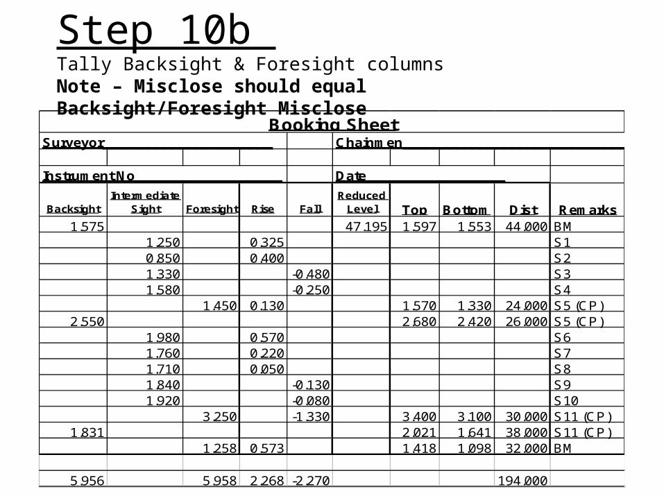
Step 10b Tally Backsight & Foresight columns Note – Misclose should equal Backsight/Foresight Misclose
Surveyor______________________ Chainmen_________________________________
Instrument No___________________ Date__________________
BacksightIntermediate
Sight Foresight Rise FallReduced
Level Top Bottom Dist Remarks1.575 47.195 1.597 1.553 44.000 BM
1.250 0.325 S10.850 0.400 S21.330 -0.480 S31.580 -0.250 S4
1.450 0.130 1.570 1.330 24.000 S5 (CP)2.550 2.680 2.420 26.000 S5 (CP)
1.980 0.570 S61.760 0.220 S71.710 0.050 S81.840 -0.130 S91.920 -0.080 S10
3.250 -1.330 3.400 3.100 30.000 S11 (CP)1.831 2.021 1.641 38.000 S11 (CP)
1.258 0.573 1.418 1.098 32.000 BM
5.956 5.958 2.268 -2.270 194.000
Booking Sheet

Step 11
Surveyor______________________ Chainmen_________________________________
Instrument No___________________ Date__________________
BacksightIntermediate
Sight Foresight Rise FallReduced
Level Top Bottom Dist Remarks1.575 47.195 1.597 1.553 44.000 BM
1.250 0.325 47.520 S10.850 0.400 47.920 S21.330 -0.480 47.440 S31.580 -0.250 47.190 S4
1.450 0.130 47.320 1.570 1.330 24.000 S5 (CP)2.550 2.680 2.420 26.000 S5 (CP)
1.980 0.570 47.890 S61.760 0.220 48.110 S71.710 0.050 48.160 S81.840 -0.130 48.030 S91.920 -0.080 47.950 S10
3.250 -1.330 46.620 3.400 3.100 30.000 S11 (CP)1.831 2.021 1.641 38.000 S11 (CP)
1.258 0.573 47.193 1.418 1.098 32.000 BM
5.956 5.958 2.268 -2.270 -0.002 194.000
Booking Sheet
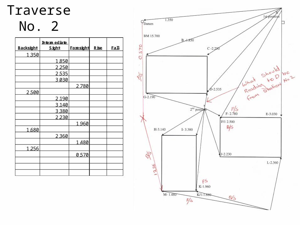
Traverse No. 2
BacksightIntermediate
Sight Foresight Rise Fall
1.3501.8502.2502.5353.030
2.7802.500
2.1903.1403.3802.230
1.9601.680
2.3601.480
1.2560.570

Traverse No. 2
Surveyor______________________ Chainmen_________________________________
Instrument No___________________ Date__________________
BacksightIntermediate
Sight Foresight Rise FallReduced
Level Top Bottom Dist Remarks1.350 BM
1.850 B2.250 C2.535 D3.030 E (CP)
2.780 F (CP)2.500 F (CP)
2.190 G3.140 H3.380 I2.230 J
1.960 K (CP)1.680 K (CP)
2.360 L1.480 M (CP)
1.256 BM0.570
6.786 -6.790 0.000 0.000
B/S 6.786 RISE 0.000 END 0.000F/S -6.790 FALL 0.000 START 0.000Misclose -0.004 0.000 0.000
Booking Sheet
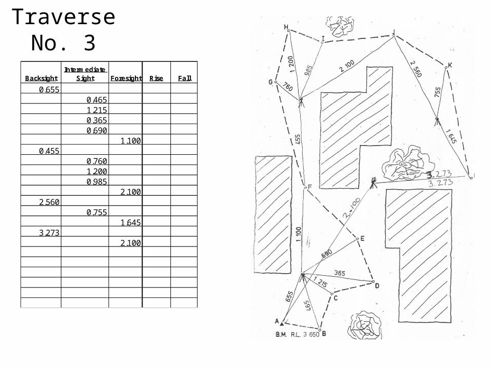
Traverse No. 3
BacksightIntermediate
Sight Foresight Rise Fall
0.6550.4651.2150.3650.690
1.1000.455
0.7601.2000.985
2.1002.560
0.7551.645
3.2732.100
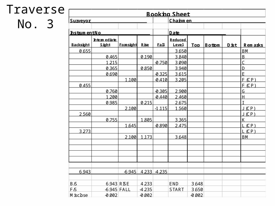
Traverse No. 3 Surveyor______________________ Chainmen_________________________________
Instrument No___________________ Date__________________
BacksightIntermediate
Sight Foresight Rise FallReduced
Level Top Bottom Dist Remarks0.655 3.650 BM
0.465 0.190 3.840 B1.215 -0.750 3.090 C0.365 0.850 3.940 D0.690 -0.325 3.615 E
1.100 -0.410 3.205 F (CP)0.455 F (CP)
0.760 -0.305 2.900 G1.200 -0.440 2.460 H0.985 0.215 2.675 I
2.100 -1.115 1.560 J (CP)2.560 J (CP)
0.755 1.805 3.365 K1.645 -0.890 2.475 L (CP)
3.273 L (CP)2.100 1.173 3.648 BM
6.943 -6.945 4.233 -4.235
B/S 6.943 RISE 4.233 END 3.648F/S -6.945 FALL -4.235 START 3.650Misclose -0.002 -0.002 -0.002
Booking Sheet
Field Exercise


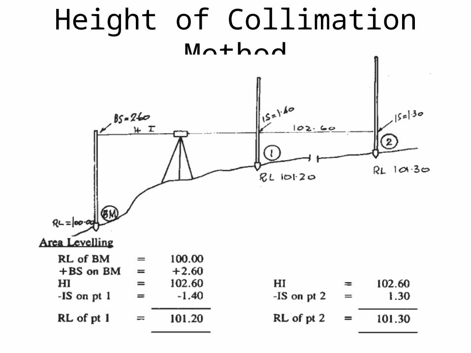
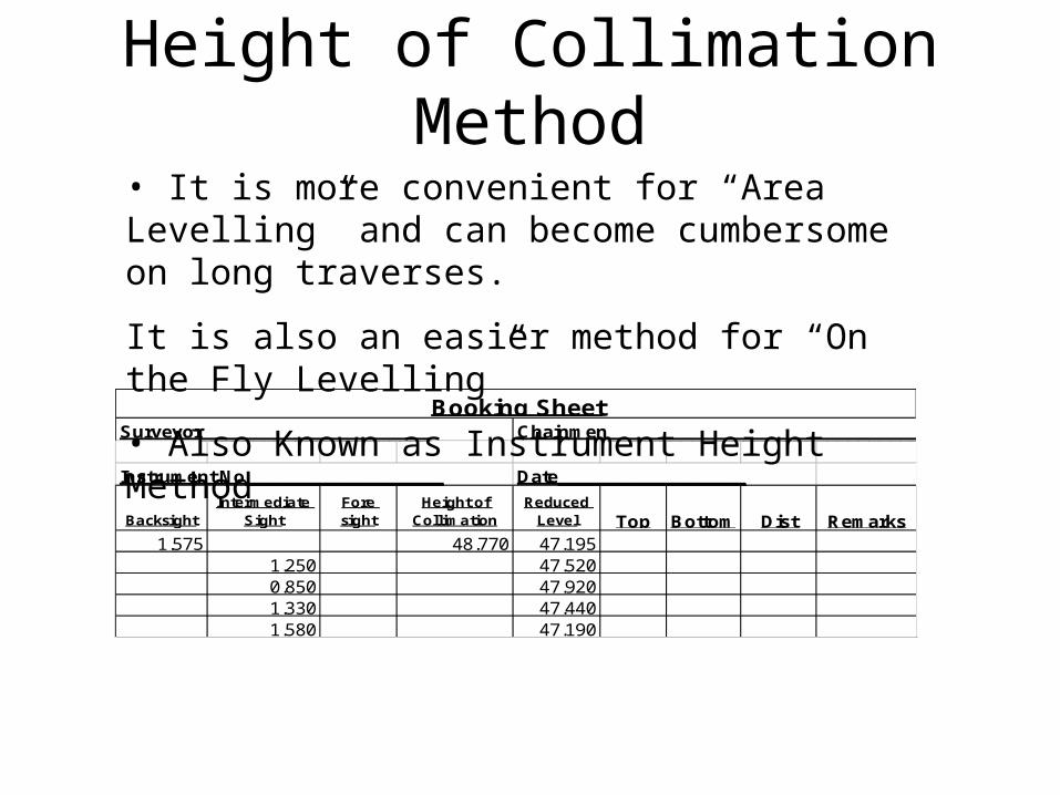
Height of Collimation Method
Height of Collimation Method
Surveyor______________________ Chainmen_________________________________
Instrument No___________________ Date__________________
BacksightIntermediate
SightFore sight
Height of Collimation
Reduced Level Top Bottom Dist Remarks
1.575 48.770 47.1951.250 47.5200.850 47.9201.330 47.4401.580 47.190
Booking Sheet
• It is more convenient for “Area Levelling” and can become cumbersome on long traverses.
It is also an easier method for “On the Fly Levelling”
• Also Known as Instrument Height Method

Traversing Exercise Height of Collimation Method

Step 1
Set up the instrument where the benchmark can be viewed within correct parameters and a reasonable number of sights can be viewed. This location is identified as L1 circled in red
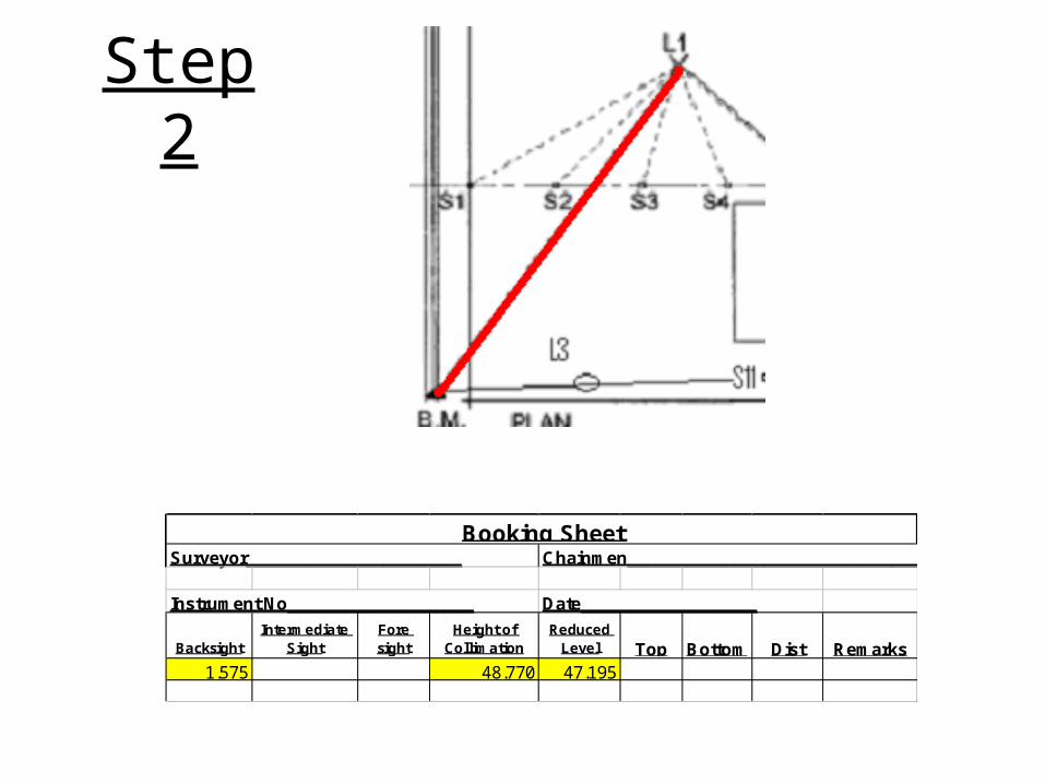
Step 2
Surveyor______________________ Chainmen_________________________________
Instrument No___________________ Date__________________
BacksightIntermediate
SightFore sight
Height of Collimation
Reduced Level Top Bottom Dist Remarks
1.575 48.770 47.195
Booking Sheet

Step 3
Surveyor______________________ Chainmen_________________________________
Instrument No___________________ Date__________________
BacksightIntermediate
SightFore sight
Height of Collimation
Reduced Level Top Bottom Dist Remarks
1.575 48.770 47.1951.250 47.520 S10.850 47.920 S21.330 47.440 S31.580 47.190 S4
Booking Sheet

Step 4
Surveyor______________________ Chainmen_________________________________
Instrument No___________________ Date__________________
BacksightIntermediate
SightFore sight
Height of Collimation
Reduced Level Top Bottom Dist Remarks
1.575 48.770 47.195 BM1.250 47.520 S10.850 47.920 S21.330 47.440 S31.580 47.190 S4
1.450 48.770 S5
Booking Sheet

Step 5
Surveyor______________________ Chainmen_________________________________
Instrument No___________________ Date__________________
BacksightIntermediate
SightFore sight
Height of Collimation
Reduced Level Top Bottom Dist Remarks
1.575 48.770 47.195 BM1.250 47.520 S10.850 47.920 S21.330 47.440 S31.580 47.190 S4
2.550 1.450 49.870 47.320 S5
Booking Sheet
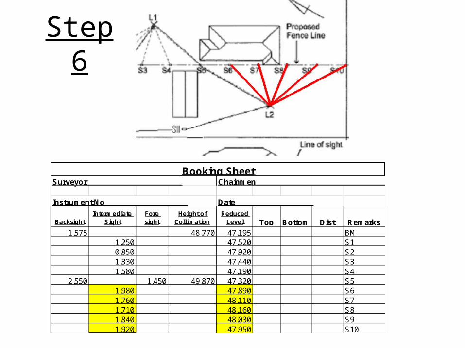
Step 6
Surveyor______________________ Chainmen_________________________________
Instrument No___________________ Date__________________
BacksightIntermediate
SightFore sight
Height of Collimation
Reduced Level Top Bottom Dist Remarks
1.575 48.770 47.195 BM1.250 47.520 S10.850 47.920 S21.330 47.440 S31.580 47.190 S4
2.550 1.450 49.870 47.320 S51.980 47.890 S61.760 48.110 S71.710 48.160 S81.840 48.030 S91.920 47.950 S10
Booking Sheet

Step 7
Surveyor______________________ Chainmen_________________________________
Instrument No___________________ Date__________________
BacksightIntermediate
SightFore sight
Height of Collimation
Reduced Level Top Bottom Dist Remarks
1.575 48.770 47.195 BM1.250 47.520 S10.850 47.920 S21.330 47.440 S31.580 47.190 S4
2.550 1.450 49.870 47.320 S51.980 47.890 S61.760 48.110 S71.710 48.160 S81.840 48.030 S91.920 47.950 S10
3.250 46.620 S11 (CP)
Booking Sheet

Step 8
Surveyor______________________ Chainmen_________________________________
Instrument No___________________ Date__________________
BacksightIntermediate
Sight Fore sightHeight of
CollimationReduced
Level Top Bottom Dist Remarks1.575 48.770 47.195 BM
1.250 47.520 S10.850 47.920 S21.330 47.440 S31.580 47.190 S4
2.550 1.450 49.870 47.320 S51.980 47.890 S61.760 48.110 S71.710 48.160 S81.840 48.030 S91.920 47.950 S10
1.831 3.250 48.451 46.620 S11 (CP)1.258 47.193 BM
Booking Sheet

Step 9 Tally Backsight & Foresight columns
Surveyor______________________ Chainmen_________________________________
Instrument No___________________ Date__________________
BacksightIntermediate
Sight Fore sightHeight of
CollimationReduced
Level Top Bottom Dist Remarks1.575 48.770 47.195 BM
1.250 47.520 S10.850 47.920 S21.330 47.440 S31.580 47.190 S4
2.550 1.450 49.870 47.320 S51.980 47.890 S61.760 48.110 S71.710 48.160 S81.840 48.030 S91.920 47.950 S10
1.831 3.250 48.451 46.620 S11 (CP)1.258 47.193 BM
5.956 5.9585.958
-0.002 Misclose
Booking Sheet

Definition - Misclose
• Definition – Misclose- is when closing of a traverse due to errors in readings and instrument limitations there is a discrepancy.
• The allowable discrepancy is (12 x square root of traverse in kilometres)

Traverse Misclose
• Traverse Length = 190 metres
• Allowable Misclose = 12 x SQRT(0.190)= 12 x 0.4359= 5.23mm

Step 10 Surveyor______________________ Chainmen_________________________________
Instrument No___________________ Date__________________
BacksightIntermediate
Sight Fore sightHeight of
CollimationReduced
Level Top Bottom Dist Remarks1.575 48.770 47.195 BM
1.250 47.520 S10.850 47.920 S21.330 47.440 S31.580 47.190 S4
2.550 1.450 49.870 47.320 S51.980 47.890 S61.760 48.110 S71.710 48.160 S81.840 48.030 S91.920 47.950 S10
1.831 3.250 48.451 46.620 S11 (CP)1.258 47.193 BM
5.956 5.9585.958
-0.002 Misclose
End RL 47.193Start BM 47.195Misclose -0.002
Booking Sheet


