This article was downloaded by: [McMaster University]On: 19 November 2014, At: 09:03Publisher: Taylor & FrancisInforma Ltd Registered in England and Wales Registered Number: 1072954 Registered office: MortimerHouse, 37-41 Mortimer Street, London W1T 3JH, UK
Welding InternationalPublication details, including instructions for authors and subscription information:http://www.tandfonline.com/loi/twld20
Welding of stainless‐duplex steels. Properties ofwelded jointsJ Brozda a & M Lomozik aa Department for Investigations into Weldability and Welded Constructions , Institute ofWelding ,Published online: 09 Dec 2009.
To cite this article: J Brozda & M Lomozik (2002) Welding of stainless‐duplex steels. Properties of welded joints, WeldingInternational, 16:1, 5-12, DOI: 10.1080/09507110209549482
To link to this article: http://dx.doi.org/10.1080/09507110209549482
PLEASE SCROLL DOWN FOR ARTICLE
Taylor & Francis makes every effort to ensure the accuracy of all the information (the “Content”) containedin the publications on our platform. However, Taylor & Francis, our agents, and our licensors make norepresentations or warranties whatsoever as to the accuracy, completeness, or suitability for any purposeof the Content. Any opinions and views expressed in this publication are the opinions and views of theauthors, and are not the views of or endorsed by Taylor & Francis. The accuracy of the Content should notbe relied upon and should be independently verified with primary sources of information. Taylor and Francisshall not be liable for any losses, actions, claims, proceedings, demands, costs, expenses, damages, andother liabilities whatsoever or howsoever caused arising directly or indirectly in connection with, in relationto or arising out of the use of the Content.
This article may be used for research, teaching, and private study purposes. Any substantial or systematicreproduction, redistribution, reselling, loan, sub-licensing, systematic supply, or distribution in anyform to anyone is expressly forbidden. Terms & Conditions of access and use can be found at http://www.tandfonline.com/page/terms-and-conditions
Welding International 2002 16 (1) 5-12Selected from Biuletyn Instytutu Spawalnictwa 2001 45 (2) 25-33; Reference BI/01/2/25; Translation 2859
Welding of stainless-duplex steels. Properties of weldedjoints
J B R O Z D A a n d M L O M O Z I KDepartment for Investigations into Weldability and Welded Constructions. Institute of Welding
Introduction
Alloys with anticorrosive properties and especially stain-less steels, are now widely used in a variety of installa-tions in the chemical and petrochemical industries, infood processing, in cellulose and paper industry, in mo-tor manufacture, atomic power engineering, as well asin the exploitation of natural gas and oil. By virtue ofproviding the required resistance to corrosion in differ-ent environments they contribute to the lengthening ofthe working life and the reduction in the cost of a rangeof constructional elements. Many production systems andinstallations call for the use of elements welded in stainlesssteels, including also those of the duplex variety.
More recently, the Biuletyn Instytutu Spawalnictwa(The Institute of Welding Bulletin) published a seriesof papers by foreign authors35 on the subject of the weldingof duplex steels. This reflects the interest in the Polishmarket of corrosion-resistant steel constructions shownby the manufacturers of filler materials. In view of thepotentially increased use of duplex-stainless steels inPoland's industry, The Institute of Welding, fulfillingits statutory obligation, initiated an investigation - fi-nanced by the Committee for Scientific Research - intothe conditions of welding and the properties of jointsmade in duplex steels.6 Fundamental characteristics ofsuch steels, and the results of the investigation are dis-cussed in this paper.
General characteristics of duplex stainlesssteels
- lower, than for the austenitic steels, coefficients of ther-mal expansion,
- high degree of resistance to corrosion, especially to pit-ting and crevice corrosion that results from a highercontent of chromium and the presence of molybdenumand nitrogen.
A fundamental fault of the duplex-type steels is theirtendency to precipitate brittle phases at elevated tem-peratures (brittleness 474°C, sigma phase). Precipita-tion of those phases reduces the resistance to corrosion,lowers ductility, and, also, impact strength of the weldedjoint.1-2-7"9
Chemical composition, microstructure andclassification of duplex steels
The fundamental alloying elements of duplex steels arechromium, nickel, molybdenum and nitrogen. Chromiumand molybdenum, as the ferrite generating agents, sta-bilise the structure of ferrite, whereas nickel and nitro-gen tend to increase the content of austenite and alsothe temperature range within which it exists. In the solidsolution, nitrogen raises the level of hardness and thereforeincreases the strength of the duplex steel. Further, chro-mium, molybdenum and nitrogen increase the resistanceof duplex steels to pitting and crevice corrosion in envi-ronments containing chlorides. Resistivity of steels topitting is expressed by the Pitting Resistance Equiva-lent (PREN) which is defined by the following equat-ion:13-10
Two-phase steels of austenitic-ferritic structures, knownas duplex steels, constitute an alternative to the single-phase austenite and ferritic steels. They combine goodproperties of these two steel grades. This is due to thefact that ferrite provides the required tensile strengthand resistance to stress corrosion, whereas austenite en-sures both good ductility and impact strength.
Basic advantages of duplex steels are as follows:1-2
- a relatively low cost of production in view of the lowcontent of the expensive and scarce nickel,
- high yield stress which makes it possible to reduce thethicknesses of constructional elements,
PREN = %Cr 3.3%Mo + 16%N
Based on the value of the PREN, several grades ofduplex steels can be distinguished and are listed in Ta-ble 1.
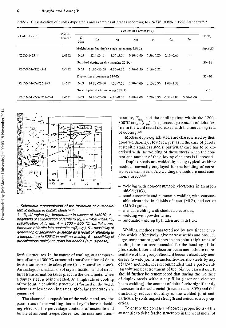
The generation of diphasé structures in duplex steelsis shown diagrammatically in Fig 1.
Weldability and the welding of duplex steels .
Duplex grade steels solidify and crystallise in tempera-tures in excess of 1450°C and possess, initially, delta
Dow
nloa
ded
by [
McM
aste
r U
nive
rsity
] at
09:
03 1
9 N
ovem
ber
2014
Brozda and Lomozik
Table 1 Classification of duplex-type steels and examples of grades according to PN-EN 10088-1: 1998 Standard1
Grade of steel
X2CrNiN23-4
X2CrNiMoN22-5-3
X2CrNiMoCuN25-6-3
X2CrNiMoCuWN27-7-4
Materialnumber C
Max
Content of element (9%)
Cr Ni Mo N Cu W
Molybdenum free duplex steels containing 23%Cr about 25
1.4362 0.03 22.0^-24.0 3.50^-5.50 0.10^0.60 0.50-=-0.20 0.10^-0.60
Standard duplex steels containing 22%Cr 30-=-36
1.4462 0.03 21.00-^23.00 4.50H-6.50 2.50-=-3.50 O.IOH-0.22
Duplex steels containing 23%Cr 32^-40
1.4507 0.03 24.00-=-26.00 5.50^-7.50 2.70H-4.00 0.15^-0.30 1.00^-2.50
Superduplex steels containing 25% Cr >40
1.4501 0.03 24.00-^26.00 6.00^-8.00 3.00-M.0O O.2O-=-O.30 0.50-^1.00 0.50-=-1.00
y
Ä
Cr 30 25 20 15
1 Schematic representation of the formation of austenitic-ferritic diphasé in duplex steels1 A1011
1 - liquid region (L), temperature in excess of 1450°C, 2 -beginning of solidification of ferrite (a (5), 3- 1450-1300 °C,solidification of ferrite, 4 - 1300 - 800 °C, partial trans-formation of ferrite into austenite (a(S)^y), 5 - possibility ofgeneration of secondary austenite as a result of reheating toa temperature to 800°C in multirun welding; 6 - possibility ofprecipitations mainly on grain boundaries (e.g. cr-phase).
ferrite structures. In the course of cooling, at a tempera-ture of some 1300°C, structural transformation of deltaferrite into austenite takes place (5 —> y transformation).An analogous mechanism of crystallisation, and of struc-tural transformation takes place in the weld metal whena duplex steel is being welded. At a high rate of coolingof the joint, a dendritic structure is formed in the weld,whereas at lower cooling rates, globular structures aregenerated.
The chemical composition of the weld metal, and theparameters of the welding thermal cycle have a decid-ing effect on the percentage contents of austenite andferrite at ambient temperatures, i.e. the maximum tem-
perature, rmax, and the cooling time within the 1200-800°C range (?12/8). The percentage content of delta fer-rite in the weld metal increases with the increasing rateof cooling.1'10
Modern duplex-grade steels are characterised by theirgood weldability. However, just as in the case of purelyaustenitic stainless steels, particular care has to be ex-ercised with the welding of these steels when the con-tent and number of the alloying elements is increased.
Duplex steels are welded by using typical weldingmethods normally employed for the bonding of corro-sion-resistant steels. Arc welding methods are most com-monly used:1'3'19
- welding with non-consumable electrodes in an argonshield (TIG),
- semi-automatic and automatic welding with consum-able electrodes in shields of inert (MIG), and active(MAG) gases,
- manual welding with shielded electrodes,- welding with powder wires,- automatic welding by hidden arc with flux.
Welding methods characterised by low linear ener-gies which, effectively, give narrow welds and producelarge temperature gradients in the joint (high rates ofcooling) are not recommended for the bonding of du-plex steels. Laser and electron-beam methods are repre-sentative of this group. Should it become absolutely nec-essary to weld joints in austenitic-ferritic steels by anyof those methods, it is recommended that a post-weld-ing solution heat treatment of the joint be carried out. Itshould further be remembered that during the weldingof duplex steels without any filler (laser and electronbeam welding), the content of delta ferrite significantlyincreases in the weld metal (it can exceed 80%) and thisdrastically reduces ductility of the welded joint and,particularly so its impact strength and anticorrosive prop-erties.
To ensure the presence of correct proportions of theaustenitic to delta ferrite structures in the weld metal of
6
Dow
nloa
ded
by [
McM
aste
r U
nive
rsity
] at
09:
03 1
9 N
ovem
ber
2014
Stainless-duplex steels
those joints for which post-welding heat treatment is notenvisaged, fillers containing higher proportions of thealloying elements (nickel and nitrogen), as compared withthose in the parent metal (usually around 9% of nickel),should be used. Fillers of chemical compositions corre-sponding to those of the welded steels are used only whenthe joint is subjected to a post-welding heat treatment.
An important problem here is that of controlling thequantity of heat supplied to the joint during the weldingoperation so that a correct austenite/ferrite ratio is ob-tained, and, also, the precipitation of harmful phases isavoided. The post-welding rate of cooling of the jointdepends on the linear energy of welding, the interruntemperature, and on the thickness of the welded part.Too high a rate of cooling results in an increase in thedelta ferrite content in the weld, reduces the impactstrength and favours the precipitation of nitrides. In con-sequence of this, the resistance to corrosion of the weldedjoint will be reduced. Similar problems attend too lowrates of cooling. These may produce brittle phases andmay also adversely affect the resistance to corrosion. Itfollows therefore that the rate of cooling should be soselected as to apply to the specific grade of duplex steel,and, also account for the type of joint and the thicknessof the welded part.
Table 2 lists values of the linear energy of welding,and of the interrun temperatures recommended by theESAB Co for various grades of duplex steels.
The type of both the shielding gas and that used toprotect the root of weld has a significant effect on thecontent of nitrogen in the weld. Too low a content ofnitrogen may lower anticorrosive properties of the joint,particularly so in the case of TIG welding. Should a riskof excessively low quantity of nitrogen in the weld arise,it is recommended that both the shielding and the root-of-weld protecting gases contain nitrogen. Examples ofgas mixtures commonly used are quoted in Ref 3.
Basic materials and fillers used in theinvestigation
The following materials were used:
- Duplex-steel plates in X2CrNiMoN 22-5-3 alloy (Ma-terial No 1.4462), 6.5, 13 and 20 mm thick.
- Filler metals manufactured by Böhler Co- rods for the TIG welding in CN 22/9N-IG grade, 2.4mm in diameter,- wires for MIG and MAG welding:solid wire in CN 22/9N-IG, 1.2 mm in diameter,powder wire in CN 22/9N-FD, 1.2 mm in diameter,
- Shielding gases: argon, argon/nitrogen mixture, argon/helium mixture, and argon/carbon dioxide mixture.
Chemical compositions of both the basic materials andfiller metals used in this investigation are listed in Ta-ble 3.
Production of welded joints
Six flat butt joints were made using the TIG, MIG, and
Table 2 Values of linear energy and interrun temperatures rec-ommended by ESAB Co for the welding of different gradesof duplex steels3-4
Duplex steel grade Linear energy [kJ/mm]Maximum interruntemperature [C°]
Molybdenum freeduplex steelscontaining 237cCr
0.5-7-2.5"
Standard duplex steels ,,containing 22îîCr
Duplex steelscontaining 25#Cr and 0.2-7-1.5"higher copper content
Superduplex steelscontaining 25% Cr
O.2H-1.5"
150-7-200
125H-200
100-7-15021
1004-150"
'Levels of energy should be selected on the basis of the thickness of theelement.2Optimal weld properties are obtained when the interrun temperature isabout 100°C
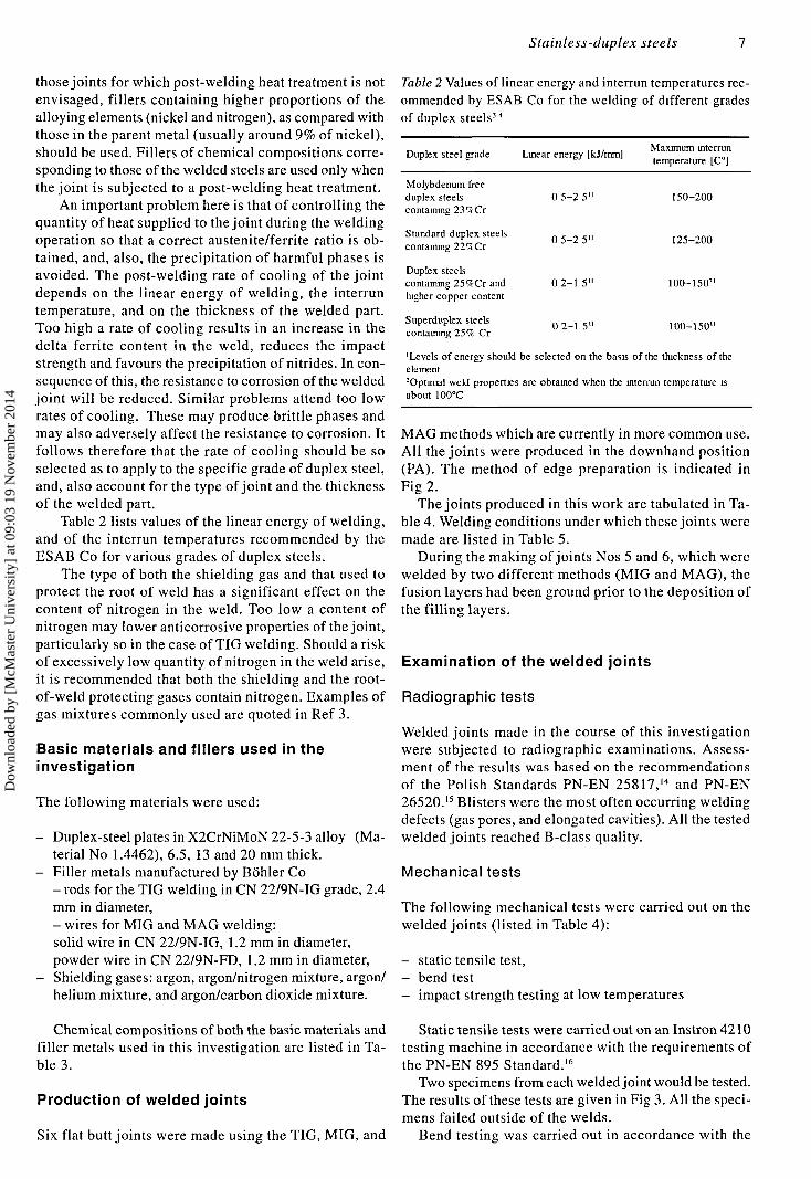
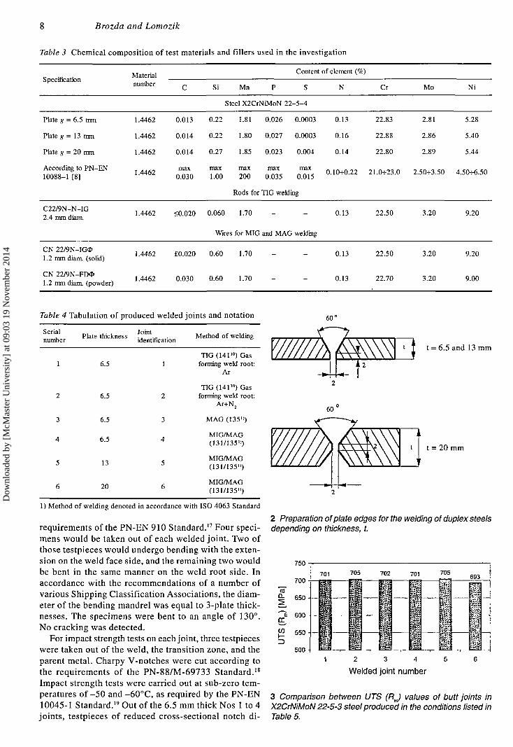
MAG methods which are currently in more common use.All the joints were produced in the downhand position(PA). The method of edge preparation is indicated inFig 2.
The joints produced in this work are tabulated in Ta-ble 4. Welding conditions under which these joints weremade are listed in Table 5.
During the making of joints Nos 5 and 6, which werewelded by two different methods (MIG and MAG), thefusion layers had been ground prior to the deposition ofthe filling layers.
Examination of the welded joints
Radiographic tests
Welded joints made in the course of this investigationwere subjected to radiographie examinations. Assess-ment of the results was based on the recommendationsof the Polish Standards PN-EN 25817,14 and PN-EN26520.15 Blisters were the most often occurring weldingdefects (gas pores, and elongated cavities). All the testedwelded joints reached B-class quality.
Mechanical tests
The following mechanical tests were carried out on thewelded joints (listed in Table 4):
- static tensile test,- bend test- impact strength testing at low temperatures
Static tensile tests were carried out on an Instron 4210testing machine in accordance with the requirements ofthe PN-EN 895 Standard.16
Two specimens from each welded joint would be tested.The results of these tests are given in Fig 3. All the speci-mens failed outside of the welds.
Bend testing was carried out in accordance with the
7
Dow
nloa
ded
by [
McM
aste
r U
nive
rsity
] at
09:
03 1
9 N
ovem
ber
2014
Brozda and Lomozik
Table 3 Chemical
Specification
composit ion of test
Materialnumber
materials and fillers used in
C Si Mn P
Steel X2CrNiMoN
the investigation
Content of element (%)
S N
22-5-4
Cr Mo Ni
Plate g = 6.5 mm
Plate g = 13 mm
Plate g = 20 mm
According to PN-EN10088-1 [8]
1.4462
1.4462
1.4462
1.4462
0.013
0.014
0.014
max0.030
0.22
0.22
0.27
max1.00
1.81
1.80
1.85
max200
0.026
0.027
0.023
max0.035
0.0003
0.0003
0.004
max0.015
0.13
0.16
0.14
0.10-^0.22
22.83
22.88
22.80
21.0-=-23.0
2.81
2.86
2.89
2.50^-3.50
5.28
5.40
5.44
4.50-f6
Rods for TIG welding
C22/9N-N-IG2.4 mm diam.
1.4462 <0.020 0.060 1.70 - - 0.13
Wires for MIG and MAG welding
22.50 3.20 9.20
CN 22/9N-IGO1.2 mm diam. (solid)
CN 22/9N-FDO1.2 mm diam. (powder)
1.4462
1.4462
£0.020 0.60 1.70
0.030 0.60 1.70
0.13
0.13
22.50
22.70
3.20
3.20
9.20
9.00
Table 4 Tabulation of produced welded joints and notation 60"
Serialnumber
Plate thickness Jointidentification
Method of welding
1
2
3
4
5
6
6.5
6.5
6.5
6.5
13
20
1
2
3
4
5
6
T1G(14110) Gasforming weld root:
Ar
TIG (14110) Gasforming weld root:
Ar+N2
MAG (135")
MIG/MAG(131/135»)
MIG/MAG(131/135")
MIG/MAG(131/135")
1) Method of welding denoted in accordance with ISO 4063 Standard
requirements of the PN-EN 910 Standard.17 Four speci-mens would be taken out of each welded joint. Two ofthose testpieces would undergo bending with the exten-sion on the weld face side, and the remaining two wouldbe bent in the same manner on the weld root side. Inaccordance with the recommendations of a number ofvarious Shipping Classification Associations, the diam-eter of the bending mandrel was equal to 3-plate thick-nesses. The specimens were bent to an angle of 130°.No cracking was detected.
For impact strength tests on each joint, three testpieceswere taken out of the weld, the transition zone, and theparent metal. Charpy V-notches were cut according tothe requirements of the PN-88/M-69733 Standard.18
Impact strength tests were carried out at sub-zero tem-peratures of -50 and -60°C, as required by the PN-EN10045-1 Standard.19 Out of the 6.5 mm thick Nos 1 to 4joints, testpieces of reduced cross-sectional notch di-
1 t = 6.5 and 13 mm
t = 20 mm
2 Preparation of plate edges for the welding of duplex steelsdepending on thickness, t.
750 -
701
1 2 3 4 5
Welded joint number
3 Comparison between UTS (RJ values of butt joints inX2CrNiMoN 22-5-3 steel produced in the conditions listed inTable 5.
8
Dow
nloa
ded
by [
McM
aste
r U
nive
rsity
] at
09:
03 1
9 N
ovem
ber
2014
Stainless-duplex steels
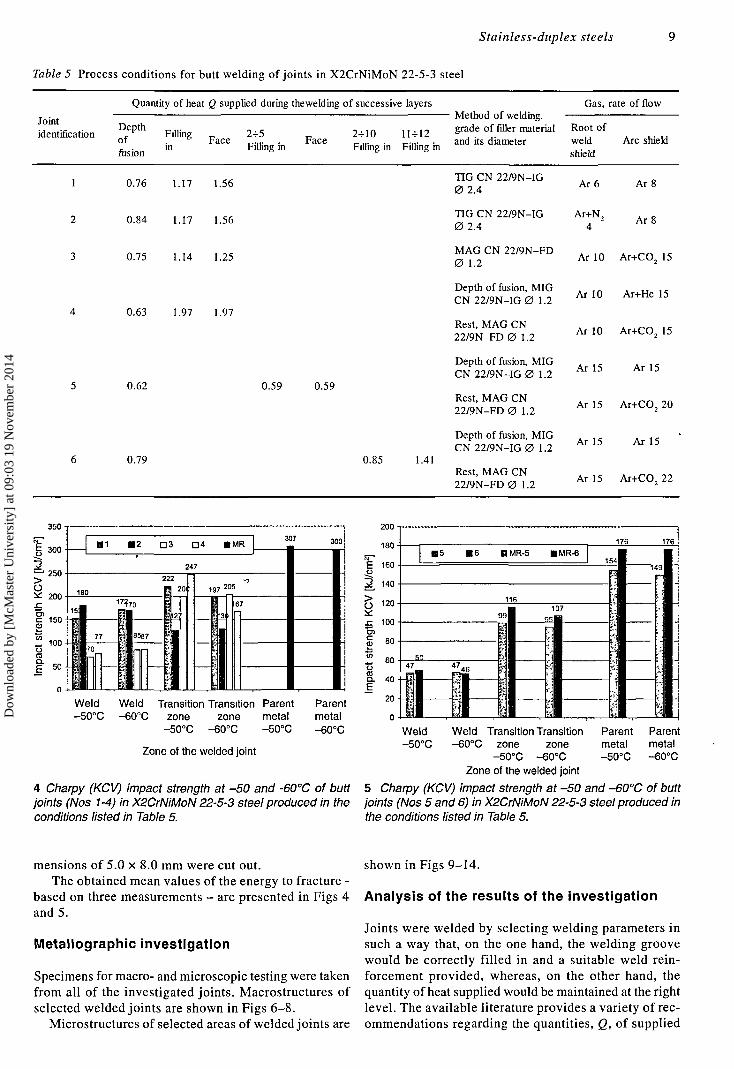
Table 5 Process conditions for butt welding of joints in X2CrNiMoN 22-5-3 steel
Quantity of heat Q supplied during thewelding of successive layersMethod of welding,
Gas, rate of flow
identification ° fe p t h Filling „ 2-5 „ 2-10 11-12 g™ie of filler material Root of
°J. in F a C e Filling in F a c e Filling in Filling in and its diameter weld Arc shieldfusion B 6 s shield
0.76 1.17 1.56
0.84 1.17 1.56
0.75 1.14 1.25
0.63 1.97 1.97
0.62
0.79
0.59 0.59
0.85 1.41
TIG CN 22/9N-IG0 2.4
TIG CN 22/9N-IG0 2.4
MAG CN 22/9N-FD0 1.2
Depth of fusion, MIGCN 22/9N-IG 0 1.2
Rest, MAG CN22/9N-FD 0 1.2
Depth of fusion, MIGCN 22/9N-IG 0 1.2
Rest, MAG CN22/9N-FD 0 1.2
Depth of fusion, MIGCN 22/9N-IG 0 1.2
Rest, MAG CN22/9N-FD 0 1.2
Ar 6 Ar 8
Ar 10 Ar+CO2 15
Ar 10 Ar+He 15
Ar 10 Ar+CO2 15
Ar 15 Ar 15
Ar 15 Ar+CO2 20
Ar 15 Ar 15
Ar 15 Ar+CO2 22
Weld Weld Transition Transition Parent Parent-50°C -60°C zone zone metal metal
-50°C -60°C -50°C -60°C
Zone of the welded joint
4 Charpy (KCV) impact strength at -50 and -60°C of buttjoints (Nos 1-4) in X2CrNiMoN 22-5-3 steel produced in theconditions listed in Table 5.
Weld Weld Transition Transition Parent Parent-50°C -60°C zone zone metal metal
-50°C -60°C -50°C -60°CZone of the welded joint
5 Charpy (KCV) impact strength at -50 and -60°C oí buttjoints (Nos 5 and 6) in X2CrNiMoN 22-5-3 steel produced inthe conditions listed in Table 5.
mensions of 5.0 x 8.0 mm were cut out.The obtained mean values of the energy to fracture -
based on three measurements - are presented in Figs 4and 5.
Metallographic investigation
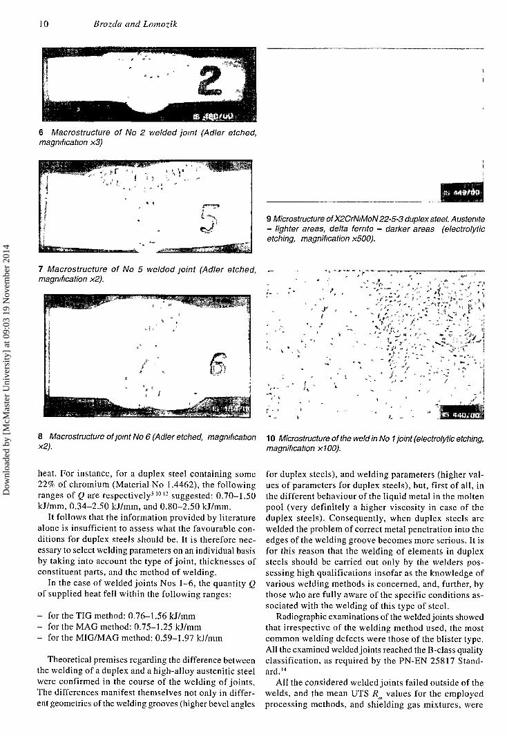
Specimens for macro- and microscopic testing were takenfrom all of the investigated joints. Macrostructures ofselected welded joints are shown in Figs 6-8.
Microstructures of selected areas of welded joints are
shown in Figs 9-14.
Analysis of the results of the investigation
Joints were welded by selecting welding parameters insuch a way that, on the one hand, the welding groovewould be correctly filled in and a suitable weld rein-forcement provided, whereas, on the other hand, thequantity of heat supplied would be maintained at the rightlevel. The available literature provides a variety of rec-ommendations regarding the quantities, Q, of supplied
9
Dow
nloa
ded
by [
McM
aste
r U
nive
rsity
] at
09:
03 1
9 N
ovem
ber
2014
10 Brozda and Lomozik
6 Macrostructure oí No 2 welded joint (Adler etched,magnification x3)
7 Macrostructure of No 5 welded joint (Adler etched,magnification x2).
8 Macrostructure of joint No 6 (Adler etched, magnificationx2).
i s .®mtim-
9 Microstructure of X2CrNiMoN 22-5-3 duplex steel. Austenite- lighter areas, delta ferrite - darker areas (electrolyticetching, magnification x500).
'*'*-,*• t „ r •* ~ .,
- • j « , - - . : .
. S
10 Microstructure of the weld in No 1 joint (electrolytic etching,magnification x100).
heat. For instance, for a duplex steel containing some22% of chromium (Material No 1.4462), the followingranges of Q are respectively51012 suggested: 0.70-1.50kJ/mm, 0.34-2.50 kJ/mm, and 0.80-2.50 kJ/mm.
It follows that the information provided by literaturealone is insufficient to assess what the favourable con-ditions for duplex steels should be. It is therefore nec-essary to select welding parameters on an individual basisby taking into account the type of joint, thicknesses ofconstituent parts, and the method of welding.
In the case of welded joints Nos 1-6, the quantity Qof supplied heat fell within the following ranges:
- for the TIG method: 0.76-1.56 kJ/mm- for the MAG method: 0.75-1.25 kJ/mm- for the MIG/MAG method: 0.59-1.97 kJ/mm
Theoretical premises regarding the difference betweenthe welding of a duplex and a high-alloy austenitic steelwere confirmed in the course of the welding of joints.The differences manifest themselves not only in differ-ent geometries of the welding grooves (higher bevel angles
for duplex steels), and welding parameters (higher val-ues of parameters for duplex steels), but, first of all, inthe different behaviour of the liquid metal in the moltenpool (very definitely a higher viscosity in case of theduplex steels). Consequently, when duplex steels arewelded the problem of correct metal penetration into theedges of the welding groove becomes more serious. It isfor this reason that the welding of elements in duplexsteels should be carried out only by the welders pos-sessing high qualifications insofar as the knowledge ofvarious welding methods is concerned, and, further, bythose who are fully aware of the specific conditions as-sociated with the welding of this type of steel.
Radiographie examinations of the welded joints showedthat irrespective of the welding method used, the mostcommon welding defects were those of the blister type.All the examined welded joints reached the B-class qualityclassification, as required by the PN-EN 25817 Stand-ard.14
All the considered welded joints failed outside of thewelds, and the mean UTS Rm values for the employedprocessing methods, and shielding gas mixtures, were
Dow
nloa
ded
by [
McM
aste
r U
nive
rsity
] at
09:
03 1
9 N
ovem
ber
2014
Stainless-duplex steels 11
( •• .
I- "'*
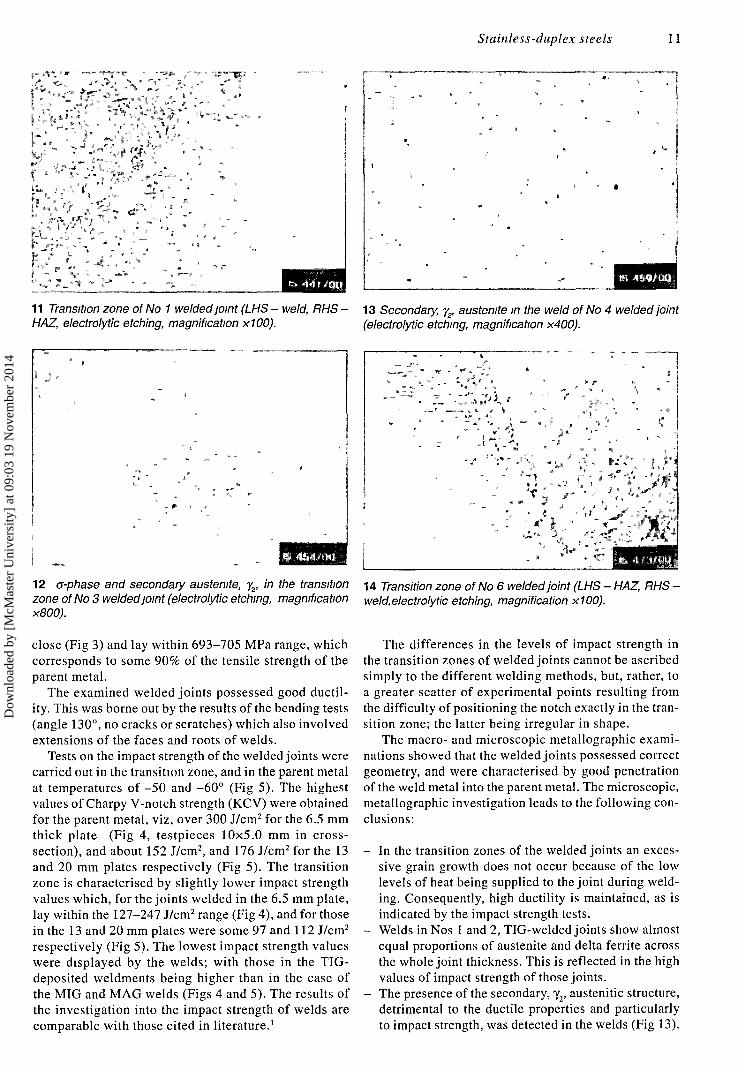
11 Transition zone of No 1 welded joint (LHS - weld, RHS •HAZ, electrolytic etching, magnification x100).
12 o-phase and secondary austenite, y2, in the transitionzone of No 3 welded joint (electrolytic etching, magnificationx800).
close (Fig 3) and lay within 693-705 MPa range, whichcorresponds to some 90% of the tensile strength of theparent metal.
The examined welded joints possessed good ductil-ity. This was borne out by the results of the bending tests(angle 130°, no cracks or scratches) which also involvedextensions of the faces and roots of welds.
Tests on the impact strength of the welded joints werecarried out in the transition zone, and in the parent metalat temperatures of -50 and -60° (Fig 5). The highestvalues of Charpy V-notch strength (KCV) were obtainedfor the parent metal, viz, over 300 J/cm2 for the 6.5 mmthick plate (Fig 4, testpieces 10x5.0 mm in cross-section), and about 152 J/cm2, and 176 J/cm2 for the 13and 20 mm plates respectively (Fig 5). The transitionzone is characterised by slightly lower impact strengthvalues which, for the joints welded in the 6.5 mm plate,lay within the 127-247 J/cm2 range (Fig 4), and for thosein the 13 and 20 mm plates were some 97 and 112 J/cm2
respectively (Fig 5). The lowest impact strength valueswere displayed by the welds; with those in the TIG-deposited weldments being higher than in the case ofthe MIG and MAG welds (Figs 4 and 5). The results ofthe investigation into the impact strength of welds arecomparable with those cited in literature.1
• 0
!
/. ' -, r. •
, • ""••" • - " • " ' • , . ' * ' " ' • , ,
V " • '. *v - '•-- ' '.
" • • ' . ' - • • • " ' ' ,L :
" " " " ' • C ' -
: ' • ' ' , • ' • • • ' / ' • • • ' . ' • . ' ; " . * , '
13 Secondary, yr austenite in the weld of No 4 welded joint(electrolytic etching, magnification x400).
14 Transition zone of No 6 welded joint (LHS - HAZ, RHS -weld.electrolytic etching, magnification x100).
The differences in the levels of impact strength inthe transition zones of welded joints cannot be ascribedsimply to the different welding methods, but, rather, toa greater scatter of experimental points resulting fromthe difficulty of positioning the notch exactly in the tran-sition zone; the latter being irregular in shape.
The macro- and microscopic metallographic exami-nations showed that the welded joints possessed correctgeometry, and were characterised by good penetrationof the weld metal into the parent metal. The microscopic,metallographic investigation leads to the following con-clusions:
- In the transition zones of the welded joints an exces-sive grain growth does not occur because of the lowlevels of heat being supplied to the joint during weld-ing. Consequently, high ductility is maintained, as isindicated by the impact strength tests.
- Welds in Nos 1 and 2, TIG-welded joints show almostequal proportions of austenite and delta ferrite acrossthe whole joint thickness. This is reflected in the highvalues of impact strength of those joints.
- The presence of the secondary, y2, austenitic structure,detrimental to the ductile properties and particularlyto impact strength, was detected in the welds (Fig 13).
Dow
nloa
ded
by [
McM
aste
r U
nive
rsity
] at
09:
03 1
9 N
ovem
ber
2014
12 Brozda and Lomozik
In the welds of the TIG-welded joints, the quantity ofthe secondary austenite is low and is mainly associatedwith the weld face zone. However, in the welds of theMAG-welded joints, the content of the secondaryaustenite is much higher and is not limited to the weldface, but is also present in the filling layers.
- In the transition zone of the MAG-welded No 3 joint,in addition to the secondary, y2 austenite, a brittle in-termediate sigma phase was also identified (Fig 12).
Conclusions
On the basis of the results of the investigation carriedout into the properties of joints welded in X2CrNiMoN22-5-3 material, the following conclusions can be drawn:
1 Adherence to recommendations for the conduct of theprocess (welding parameters which determine the quan-tity of heat to be supplied to the joint) combined with ahigh degree of the welder's expertise, makes it possi-ble to produce welded joints of good mechanical andductile properties.
2 The UTSjfl^, of the joints welded by the TIG, MIG,and MAG methods is practically the same and corre-sponds to some 90% of the tensile strength of the par-ent metal.
3 The highest impact strength values are possessed bythe welds deposited by the TIG method since acrossthe whole thickness of the joint the structure consistsof equal proportions of austenite and delta ferrite. Inthe MAG-welded joint of a lower impact strength (Ta-ble 5, No 3), undesirable structural components, suchas the secondary, y2, austenite, and sigma phase arepresent not only in the weld, but also in the transitionzone. In other joints only the secondary austenite is
present and occurs solely in the welds.
References
1 Gunn R N: 'Duplex stainless steels, Microstructure, properties andapplications'. Publ Abington Publishing, Woodhead PublishingLtd, and the Welding Institute, Abington, 1999.
2 Böhler Welding: 'Welding of chemical resistant steels'. TechnicalSeminar, 1994.
3 Karlsson L: 'Welding of corrosion resistant steels. Duplex andsuperduplex steels'. Biuletyn Instytutu Spawalnictwa 1999(1)28-33.
4 Karlsson L: 'Welding of high-alloy, stainless steels. Filler materi-als and procedures.' Biuletyn Instytutu Spawalnictwa 1999(5)72-76.
5 Ammann T H: 'Welding of duplex type steels in gas shields.'Biuletyn Instytutu Spawalnictwa 2000(5)69-74.
6 Lomozik M, Brozda J and Czwornog B: 'Investigation into theconditions of welding and properties of joints in stainless diphasesteel.' Research Report No Ad 23, 2000, The Welding Institute.
7 Kume R, Nakamura H, Mei J and Mimura H: 'Thermalembrittlement of HAZ of duplex stainless steel welds.' IIW DocIX-1794-94.
8 Karlsson L, Rigdal S and Andersson S L: 'Welding of highly al-loyed austenitic and duplex stainless steels.' IIW Doc IX-1840-96(Doc IX-H-354-96).
9 Karlsson L: 'Intermetallic phase precipitation in duplex stainlesssteels and weld metals (Metallurgy, Influence on properties, Weld-ing and testing aspects).' IIW Review Doc IX-1877-97
10 Astrom H: 'Welding of duplex stainless steel.' Publ Elga AB, Swe-den
11 Charles J: 'Duplex stainless steel for chemical tankers.' PublManchem, Cologne, 1995.
12 Urmston St: 'Welding of duplex type steels.' BOC Gazy, 1999.13 PN-EN 10088-1:1998: 'Corrosion resistant steels. Grades.'14 PN-EN 25817:1997: 'Arc-welded steel joints. Guidelines for the
determination of quality reflecting welding defects.'15. PN-EN 26520:1997: 'Classification of welding defects in welded
metal joints with explanations.'16 PN-EN 895:1995: 'Destructive testing of welded metal joints. Ten-
sile testing of transverse specimens.'17 PN-EN 910:1995: 'Destructive testing of welds. The bend test.'18 PN-88/M-69733: 'Welding. Impact strength test on butt-welded
joints.'19 PN-EN 10045-1:1994: 'Metals. Charpy impact strength test.
Method of testing.'
Dow
nloa
ded
by [
McM
aste
r U
nive
rsity
] at
09:
03 1
9 N
ovem
ber
2014


