
MIGUTan
Watertight expansion joint systems for traffic
Developed for bituminous layers, coatings, liquid sealants, and installation in concrete:permanent watertightvehicular traffichigh loading
Car parks, Multi-storey car parks,
Underground car parks
Pedestrian bridges
Exhibition halls, Kitchens
Swimming pool areas, Hospitals
Sport facilities / Stadiums

2
MIGUTan
Index to range of applications / alphabetic 3
Product description 4
Bituminous sealings (long AAS sheets – ls) 5 - 14 Coatings (short AAS sheets – ss) 15 - 26
Liquid sealings (MIGUTRIX sheets – XA) 27
MIGUTan with special cover plates 28 Installation in concrete (anchor rods / loop anchors) 29 - 32
Technical Information
The System 34 - 35
Transitions - Examples 36 - 37
Available Inserts FP / FPG 38
Profile connections 39
Terminations / Intersections 40 - 45
Wall-Connections / Connections to columns 46 - 51
Installation examples 52 - 60
Illustrations of applications 62 - 65
MIGUA – At a glance 66
Watertight expansion joint systems
MIGUTAN is a comprehensive program of watertight expansion joint systems for bituminous layers, coatings, liquid sealants, and installation in concrete.
In many buildings both public and private sectors watertight expansion joint systems is of vital importance for the protection of the building: Important building parts of car parks, multi-storey car parks, underground car parks, pedestrian bridges, exhibition halls, kitchens, swimming pool areas, hospitals, sport facilities and stadiums has to be protected from water penetration.
Well planned, long lasting, 100% watertight and solid expansion joint systems are requested. The large number of requirements regarding building physics needs individual constructive solutions with partly fundamentally different types. The common feature of all MIGUTAN systems is the unique technology of an interchangeable insert, which seals on top of the surface.
MIGUA is known as the technology leader in the field of watertight expansion joint systems in Europe. MIGUTAN offers designers and architects a proven system with a large range of applications.Supplemented by a comprehensive, well designed system of intersections, end terminations and transitions MIGUTAN offers a safe solution for each single case.
Content
Page
Information about load capacity
Symbol
Meaning pedestrians private cars lorries fork lift trucks solid plastic
DIN 1072 DIN 1055 tyres
Load capacities for fork lift trucks are based on pneumatic or rubber tyres with a contact surface of 200 x 200 mm.

3
MIGUTan Watertight expansion joint systems
Range of applications
Series Page
FP 155 NI Is 9FP 155 NI ss 19FP…/…APF 28FP(G)… /…NI XA 27FP(G)…/60 S NI Is 10 FP(G)… /60 S NI ss 20 FP(G)…/90 B NI anchor rods 29FP(G)…/90 B NI loop anchors 30
Series Page
FPG 80 NI Is 12FPG 80 NI ss 15FPG 90 NI Is 6FPG 90 NI ss 16FPG 110 NI Is 14FPG 110 NI ss 24FPI 145 B NI anchor rods 31FPI 145 NI Is 11
Series Page
FPI 145 NI ss 21FPL 85/27 NI 25FPL 85/75 B NI anchor rods 32FPSG 68 ES 26
Series Page
FP 80 NI Is 5FP 80 NI ss 15FP 90 NI Is 6FP 90 NI ss 16FP 110 NI Is 7 FP 110 NI ss 17 FP 130 NI Is 8FP 130 NI ss 18
Index in alphabetic order
Profile for bituminous sealing layer (long AAS sheets – ls)
Series Page
FP 80 NI Is 5 FP 90 NI Is 6FP 110 NI Is 7FP 130 NI Is 8FP 155 NI Is 9 FP(G)…/60 S NI Is 10 FPI 145 NI Is 11FPG 80 NI Is 12 FPG 90 NI Is 13 FPG 110 NI Is 14
Long sealing sheets are designed for the best possible connection to bituminous sealing layer. Central insert on top surface, striated stainless steel cappings and solid aluminium mounting brackets are special and important properties of our MIGUTAN system.Our FPI Systems obtain a perfect sealing without perforation of the sealing elements.
Profile for floors with coatings (short AAS sheets – ss)
Series Page
FP 80 NI ss 15 FP 90 NI ss 16 FP 110 NI ss 17 FP 130 NI ss 18 FP 155 NI ss 19 FP(G)… /60 S NI ss 20 FPI 145 NI ss 21FPG 80 NI ss 22 FPG 90 NI ss 23 FPG 110 NI ss 24 FPL 85/27 NI 25 FPSG 68 ES 26 FP…/…APF 28
Short sealing sheets ensures a perfect watertight connection to different surface protection systems (coating systems). This series has the same important properties: Central insert on top surface, striated stainless steel cappings and solid aluminium mounting brackets. Another system with stainless steel clip- on-cappings (FPL) for a cost-effective installation is available.
Profile for flexible waterproofing slurry (MIGUTrIX sheets – XA)
Series Page
FP(G)… /…NI XA 27
This innovative MIGUA Techno- logy with fibre fabric bonded sealing sheets ensures a perfect connection to flexible water-proofing slurry and liquid sealing, which are usually installed under- neath the tiles. In conjunction with 3 different smooth central inserts for hygienic areas - antibacterial and physiologically safe.In conjunction with special cappings particularly suited for swimming pool areas.
Profile for installation in flush concrete (anchor rods / loop anchors)
Series Page
FP(G)…/90 B NI anchor rods 29FP(G)…/90 B NI loop anchors 30FPI 145 B NI anchor rods 31FPL 85/75 B NI anchor rods 32
Profiles with anchor rods or loop anchors for flush installation in concrete decks with coating systems.Slideable anchor rods or loop anchors for adjustable welding to the rein-forcement allow much flexibility and easy installation. Suitable for different load capacities through the use of anchor rods or loop anchors.

4
MIGUTan
Typical uses
MIGUTAN systems have been used for more than 30 years for watertight sealing in car parks, multi-storey car parks, garages, underground parking, swimming pool areas, kitchen, pedestrian bridges, airports, etc.A large number of reference projects can be provided. Special properties
Aluminium side plates with striated aluminium mounting brak-kets, flexible sealing insert and long or short side sealing sheets (AAS-sheets) or fibre fabric bonded sheets on both sides. AAS-sheets are made of quality MIGUFLEX, which is non-abrasive, weather resistant, resistant against salt and waste water (hydrogen sulphide, microbes, bacteria). The AAS-sheets can be used with hot bitumen.
The profiles are provided with 300 mm wide AAS sheets on both sides, which are striated to provide best possible connection with the sealing layer to give a watertight connection in different sealing systems acc. to DIN 18195 (e.g.: bituminous sealing, etc.).
Stainless steel cappings, 2,5 mm thick , fixed by screws, provide protection for the parts of the system remaining visible and exposed after installation. These capping sections will simulta-neously apply the required pressure upon the sealing insert and AAS-sheets.
Stainless steel cappings are striated to provide skid resistance.
Flexible sealing insert is watertight-weldable, resistant to weather, benzene, fuel, oil and salt. The insert has a double-web to provide multilayered protection against water leakage.
The central sealing insert is interchangeable (even after installation) without disrupting the surface.
The central sealing insert on the top surface ensures an impermeable barrier against moisture and salt.
Continuous sealing elements ensure 100% watertightness for the whole joint system.
Test certificate: An official test certificates for watertightness and load capacity is available and can be forwarded on request.
FireproofingExtensive fire tests have been carried out for our Series FP 80 Ni, FP 90 NI, FPG 90 Ni and FP 110 NI at the MPA NrW. In accordance with test certi-ficate and test report No. 230007088 these are approved. According to EN 13501-1 all products can be classified to Bfl-s1 (fire resistant floor coverings, not burning/dripping).
Intersections and transitions can be fabricated for the most complicated joint systems. We ensure a perfect fit by taking measurements on site (complete systems including all inter- sections, transitions and connections will be done in our works).
Production lengths can be connected by staggering the joint in the individual aluminium profiles or by using connection pins.
Suitability in accordance with WHG § 19 For applications that are run according to WHG § 19, we offer individual solutions. If needed, please contact us.
Important notes
Due to its low installation height, the height 25 mm should notbe used in connection with asphalt.
Minimum joint width: Due to the shape of the central insert the following minimum joint widths have to be considered:
- 50 mm for FP 110/25 NI- 75 mm for FP 130/25 NI and FP 130/35 NI- 95 mm for FP 155/... for heights less than 80 mm
Fixing: For the fixing of the profile height 35 mm and 45 mmin connection with long AAS-sheets, countersunk head screws MMS-F 7,5 x 80 have to be used. Distance between screws approx. 300 mm.
Fixing with chem. anchors or MMS P 10 x 70 with a distance of approx. 300 mm has to be used for the following profiles:- FP 80/25 Ni with short AAS-sheets- Series FP .../60 S NiFor all other profiles the distance for the fixing is 350 mm.
Cover plates: Vertical movements cannot be absorbed if stainless steel cover plates are used.
MIGUTAN in swimming pool areas: If the MIGUTAN profiles are used in swimming pool areas special stainless steel alloys, which are additionally pickled is necessary, due to the resistance to chlo-ride ions. Such usage has to be mentioned in all specifications and inquiries.
Stainless steel cappings: The stainless steel cappings are secured to the top of the profile with screws tightened to 7 Nm torque to provide continuous constant pressure.
Installation:Application and installation instructions will be provided on request. Please contact us. As an alternative you can download it from our website www.migua.com
Fixing by means of anchor rods or loop anchorsFor fixing of the profiles on concrete slabs, additional adjusting devices can be screwed to the aluminium side plates of the profiles in our works and supplied on request.
Positive connection between each single length is achieved on site by means of connecting pins, which ensures a level and precise transition.
For weight reasons and because of the better handling, we recom-mend installation of the loop anchors MIGUTAN profiles with an axial separation.
For secure fixing of the profile system, the anchor rods or the loop anchors should be welded to the reinforcement. A connection joint of approx. 10 x 20 mm must be provided adjacent to each side of the stainless steel capping. This connection joint is filled with seal-ant, e.g. Polyurethane. The stainless steel cappings have a roughe-ned vertical surface which will improve adhesion with a sealant.Proper and economical formation of the connection joint by using connection joint filler profile AAP 50/20.
Load capacities for fork lift trucks are based on pneumatic or rubber tyres with a contact surface of 200 x 200 mm.
Watertight expansion joint systems
Product description: MIGUTAN expansion joint system with interchangeable central insert

5
MIGUTan
b t
b s
h
b f maxbf max
bs
bt
h
FP 80 NI ls
Profile Joint width Total Visible width Total width Installation Load capacity Load capacity Load capacity max. Movement of profile of profile height bf max ∆bf bs bt h [mm] [mm] [mm] [mm] [mm] [kN] [kN] [kg/mm width of wheel]
FP 80/ 25 NI ls 45 20 (± 10) 82 209 25 – – –FP 80/ 35 NI ls 45 20 (± 10) 82 209 35 600 130 6,5FP 80/ 45 NI ls 45 20 (± 10) 82 198 46 300 70 –FP 80/ 60 NI ls 45 20 (± 10) 82 209 60 300 30 –FP 80/ 80 NI ls 45 20 (± 10) 82 209 81 120 30 –FP 80/ 95 NI ls 45 20 (± 10) 82 209 97 60 – –FP 80/115 NI ls 45 20 (± 10) 82 209 117 60 – –
Watertight expansion joint systems
for bituminous layer(long AAS sheets)
Profiles with an installation height from 60 mm upwards can be adjusted to higher load capacity. Please ask for our advice.
Official test certificates for watertightness availableCentral insert with double-web to provide multilayered protection
Striated stainless steel cappings ensures good skid resistance100% watertight by max. pressure Central insert on top surfaceVisual inspection and replacement without disrupting the surface
Long AAS sheets on both sides with striations Best possible connection with the sealing layer
Mounting brackets are made of high strength aluminiumHigh loads without any risk of rust
Fire tested Bfl-s1(flame retardant) acc. to DIN EN 13501-1

6
MIGUTan
b t
b s
h
b f maxbf max
bs
bt
h
FP 90 NI ls
Profile Joint width Total Visible width Total width Installation Load capacity Load capacity Load capacity max. Movement of profile of profile height bf max ∆bf bs bt h [mm] [mm] [mm] [mm] [mm] [kN] [kN] [kg/mm width of wheel] FP 90/ 25 NI ls 60 40 (± 20) 95 222 25 – – –FP 90/ 35 NI ls 60 40 (± 20) 95 222 35 600 130 –FP 90/ 45 NI ls 60 40 (± 20) 95 211 46 300 70 –FP 90/ 60 NI ls 60 40 (± 20) 95 222 60 300 30 –FP 90/ 80 NI ls 60 40 (± 20) 95 222 81 120 30 –FP 90/ 95 NI ls 60 40 (± 20) 95 222 97 60 – –FP 90/115 NI ls 60 40 (± 20) 95 222 117 60 – –
Watertight expansion joint systems
for bituminous layer(long AAS sheets)
Official test certificates for watertightness availableCentral insert with double-web to provide multilayered protection Central insert on top surfaceVisual inspection and replacement without disrupting the surface
Striated stainless steel cappings ensures good skid resistance100% watertight by max. pressure Long AAS sheets on both sides with striations Best possible connection with the sealing layer
Mounting brackets are made of high strength aluminiumHigh loads without any risk of rust
Profiles with an installation height from 60 mm upwards can be adjusted to higher load capacity. Please ask for our advice.
Fire tested Bfl-s1(flame retardant) acc. to DIN EN 13501-1

7
MIGUTan
b t
b s
h
b f maxbf max
bs
bth
FP 110 NI ls
Profile Joint width Total Visible width Total width Installation Load capacity Load capacity Load capacity max. Movement of profile of profile height bf max ∆bf bs bt h [mm] [mm] [mm] [mm] [mm] [kN] [kN] [kg/mm width of wheel] FP 110/ 25 NI ls* 75 60 (± 30) 111 238 25 – – –FP 110/ 35 NI ls 75 60 (± 30) 111 238 35 600 130 –FP 110/ 45 NI ls 75 60 (± 30) 111 227 46 300 70 –FP 110/ 60 NI ls 75 60 (± 30) 111 238 60 300 30 –FP 110/ 80 NI ls 75 60 (± 30) 111 238 81 120 30 –FP 110/ 95 NI ls 75 60 (± 30) 111 238 97 60 – –FP 110/115 NI ls 75 60 (± 30) 111 238 117 60 – –
Watertight expansion joint systems
for bituminous layer(long AAS sheets)
Central insert on top surfaceVisual inspection and replacement without disrupting the surface
Striated stainless steel cappings ensures good skid resistance100% watertight by max. pressure Long AAS sheets on both sides with striations Best possible connection with the sealing layer Mounting brackets are made of high strength aluminiumHigh loads without any risk of rust Official test certificates for watertightness availableCentral insert with double-web to provide multilayered protection
* Minimum joint width 50 mm
Profiles with an installation height from 60 mm upwards can be adjusted to higher load capacity. Please ask for our advice.
Fire tested Bfl-s1(flame retardant) acc. to DIN EN 13501-1

8
MIGUTan
b t
b sh
b f maxbf max
bs
bt
h
FP 130 NI ls
Profile Joint width Total Visible width Total width Installation Load capacity Load capacity Load capacity max. Movement of profile of profile height bf max ∆bf bs bt h [mm] [mm] [mm] [mm] [mm] [kN] [kN] [kg/mm width of wheel] FP 130/25 NI ls* 100 90 (± 45) 133 260 25 – – –FP 130/35 NI ls* 100 90 (± 45) 133 260 35 600 130 –FP 130/45 NI ls 100 90 (± 45) 133 249 46 90 70 –FP 130/60 NI ls 100 90 (± 45) 133 260 60 60 35 –FP 130/80 NI ls 100 90 (± 45) 133 260 81 60 35 –FP 130/95 NI ls 100 90 (± 45) 133 260 97 private cars – –FP 130/115 NI ls 100 90 (± 45) 133 260 117 private cars – –
Watertight expansion joint systems
for bituminous layer(long AAS sheets)
Central insert on top surfaceVisual inspection and replacement without disrupting the surface Striated stainless steel cappings ensures good skid resistance100% watertight by max. pressure Long AAS sheets on both sides with striations Best possible connection with the sealing layer
Mounting brackets are made of high strength aluminiumHigh loads without any risk of rust
Official test certificates for watertightness availableCentral insert with double-web to provide multilayered protection
* Minimum joint width 75 mm
Profiles with an installation height from 60 mm upwards can be adjusted to higher load capacity. Please ask for our advice.

9
MIGUTan
b t
b s
h
b f maxbf max
bs
bt
h
FP 155 NI ls
Profile Joint width Total Visible width Total width Installation Load capacity Load capacity Load capacity max. Movement of profile of profile height bf max ∆bf bs bt h [mm] [mm] [mm] [mm] [mm] [kN] [kN] [kg/mm width of wheel] FP 155/ 25 NI ls* 120 120 (± 60) 155 282 25 – – –FP 155/ 35 NI ls* 120 120 (± 60) 155 282 35 120 35 –FP 155/ 45 NI ls* 120 120 (± 60) 155 271 46 60 35 –FP 155/ 60 NI ls* 120 120 (± 60) 155 282 60 35 35 –FP 155/ 80 NI ls* 120 120 (± 60) 155 282 81 35 35 –FP 155/ 95 NI ls 120 120 (± 60) 155 282 97 private cars – –FP 155/115 NI ls 120 120 (± 60) 155 282 117 private cars – –
Watertight expansion joint systems
for bituminous layer(long AAS sheets)
Striated stainless steel cappings ensures good skid resistance100% watertight by max. pressure Central insert on top surfaceVisual inspection and replacement without disrupting the surface
Long AAS sheets on both sides with striations Best possible connection with the sealing layer
Mounting brackets are made of high strength aluminiumHigh loads without any risk of rust
Official test certificates for watertightness availableCentral insert with double-web to provide multilayered protection
* Minimum joint width 95 mm
Profiles with an installation height from 60 mm upwards can be adjusted to higher load capacity. Please ask for our advice.

10
MIGUTan
b t
b s
h
b f maxbf max
bs
bt
h
FP(G).../60 S NI ls Heavy Duty
Profile Joint width Total Visible width Total width Installation Load capacity Load capacity Load capacity max. Movement of profile of profile height bf max ∆bf bs bt h [mm] [mm] [mm] [mm] [mm] [kN] [kN] [kg/mm width of wheel] FP 80/60 S NI ls 35 20 (± 10) 82 201 60 600 130 6,5FPG 80/60 S NI ls 35 16 (± 8) 82 201 60 600 130 6,5FP 90/60 S NI ls 50 40 (± 20) 95 214 60 600 130 –FPG 90/60 S ls 50 20 (± 10) 95 214 60 600 130 4,3FP 110/60 S NI ls 65 60 (± 30) 111 230 60 600 130 –FPG 110/60 S NI ls 65 40 (± 20) 111 230 60 600 130 –FP 130/60 S NI ls 90 90 (± 45) 133 260 60 600 130 – FP 155/60 S NI ls 110 120 (± 60) 155 274 60 300 70 –
Watertight expansion joint systems
for bituminous layer(long AAS sheets)
Striated stainless steel cappings ensures good skid resistance100% watertight by max. pressure Central insert on top surfaceVisual inspection and replacement without disrupting the surface
Long AAS sheets on both sides with striations Best possible connection with the sealing layer
Mounting brackets are made of high strength aluminiumHigh loads without any risk of rust
Official test certificates for watertightness availableCentral insert with double-web to provide multilayered protection

11
MIGUTan
b t
b s
h
b f max bf max
h
bs
bt
FPI 145 NI ls Heavy Duty
Watertight expansion joint systems
for bituminous layer(long AAS sheets)
Profile Joint width Total Visible width Total width Installation Load capacity Load capacity Load capacity max. Movement of profile of profile height bf max ∆bf bs bt h [mm] [mm] [mm] [mm] [mm] [kN] [kN] [kg/mm width of wheel] FPI 145/28 NI ls 50* 60 (± 30) 145 239 28 600 130 –FPI 145/40 NI ls 100 60 (± 30) 145 239 40 600 130 –FPI 145/60 NI ls 100 60 (± 30) 145 274 60 600 130 –
Long AAS sheets on both sides with striations Best possible connection with the sealing layer
Central insert on top surfaceVisual inspection and replacement without disrupting the surface
Striated stainless steel cappings ensures good skid resistance100% watertight by max. pressure
Perfect sealingSpecial design without perforation of the sealing elements
Mounting brackets are made of high strength aluminiumHigh loads without any risk of rust
* For load capacity by private cars only, the maximum joint width can be increased to 100 mm

12
MIGUTan
hb t
b s
b f maxbf max
bs
bt
h
Watertight expansion joint systems
FPG 80 NI ls smooth Insert
for bituminous layer(long AAS sheets)
Profile Joint width Total Visible width Total width Installation Load capacity Load capacity Load capacity max. Movement of profile of profile height bf max ∆bf bs bt h [mm] [mm] [mm] [mm] [mm] [kN] [kN] [kg/mm width of wheel]
FPG 80/25 NI ls 45 16 (± 8) 82 209 25 600 130 6,5FPG 80/35 NI ls 45 16 (± 8) 82 209 35 600 130 6,5FPG 80/45 NI ls 45 16 (± 8) 82 198 46 300 70 –FPG 80/60 NI ls 45 16 (± 8) 82 209 60 300 30 –FPG 80/80 NI ls 45 16 (± 8) 82 209 81 120 30 –FPG 80/95 NI ls 45 16 (± 8) 82 209 97 60 – – FPG 80/115 NI ls 45 16 (± 8) 82 209 117 60 – –
Official test certificates for watertightness availableCentral insert with double-web to provide multilayered protection
Striated stainless steel cappings ensures good skid resistance100% watertight by max. pressure
Smooth central insert for increased hygienic requirements Antibacterial and physiologically safe
Central insert on top surfaceVisual inspection and replacement without disrupting the surface
Mounting brackets are made of high strength aluminiumHigh loads without any risk of rust
Profiles with an installation height from 60 mm upwards can be adjusted to higher load capacity. Please ask for our advice.

13
MIGUTan
b t
b s
h
b f maxbf max
bs
bt
h
FPG 90 NI ls smooth Insert
Profile Joint width Total Visible width Total width Installation Load capacity Load capacity Load capacity max. Movement of profile of profile height bf max ∆bf bs bt h [mm] [mm] [mm] [mm] [mm] [kN] [kN] [kg/mm width of wheel]
FPG 90/ 25 NI ls 60 20 (± 10) 95 222 25 – – –FPG 90/ 35 NI ls 60 20 (± 10) 95 222 35 600 130 4,3FPG 90/ 45 NI ls 60 20 (± 10) 95 211 46 300 70 –FPG 90/ 60 NI ls 60 20 (± 10) 95 222 60 300 30 –FPG 90/ 80 NI ls 60 20 (± 10) 95 222 81 120 30 –FPG 90/ 95 NI ls 60 20 (± 10) 95 222 97 60 – –FPG 90/115 NI ls 60 20 (± 10) 95 222 117 60 – –
Watertight expansion joint systems
for bituminous layer(long AAS sheets)
Smooth central insert for increased hygienic requirements Antibacterial and physiologically safe
Central insert on top surfaceVisual inspection and replacement without disrupting the surface
Striated stainless steel cappings ensures good skid resistance100% watertight by max. pressure
Mounting brackets are made of high strength aluminiumHigh loads without any risk of rust
Official test certificates for watertightness availableCentral insert with double-web to provide multilayered protection
Profiles with an installation height from 60 mm upwards can be adjusted to higher load capacity. Please ask for our advice.
Fire tested Bfl-s1(flame retardant) acc. to DIN EN 13501-1

14
MIGUTan
b t
b s
h
b f maxbf max
bs
bth
FPG 110 NI ls smooth Insert
for bituminous layer(long AAS sheets)
Watertight expansion joint systems
Profile Joint width Total Visible width Total width Installation Load capacity Load capacity Load capacity max. Movement of profile of profile height bf max ∆bf bs bt h [mm] [mm] [mm] [mm] [mm] [kN] [kN] [kg/mm width of wheel] FPG 110/ 25 NI ls* 75 40 (± 20) 111 238 25 – – –FPG 110/ 35 NI ls 75 40 (± 20) 111 238 35 600 130 –FPG 110/ 45 NI ls 75 40 (± 20) 111 227 46 300 70 –FPG 110/ 60 NI ls 75 40 (± 20) 111 238 60 300 30 –FPG 110/ 80 NI ls 75 40 (± 20) 111 238 81 120 30 –FPG 110/ 95 NI ls 75 40 (± 20) 111 238 97 60 – –FPG 110/115 NI ls 75 40 (± 20) 111 238 117 60 – –
Striated stainless steel cappings ensures good skid resistance100% watertight by max. pressure
Smooth central insert for increased hygienic requirements Antibacterial and physiologically safe
Central insert on top surfaceVisual inspection and replacement without disrupting the surface
Mounting brackets are made of high strength aluminiumHigh loads without any risk of rust
Official test certificates for watertightness availableCentral insert with double-web to provide multilayered protection
* Minimum joint width 50 mm
Profiles with an installation height from 60 mm upwards can be adjusted to higher load capacity. Please ask for our advice.

15
MIGUTan
b t
b s
h
b f maxbf max
bs
bt
h
FP 80 NI ss
Watertight expansion joint systems
for floors with coating systems(short AAS sheets)
Profile Joint width Total Visible width Total width Installation Load capacity Load capacity Load capacity max. Movement of profile of profile height bf max ∆bf bs bt h [mm] [mm] [mm] [mm] [mm] [kN] [kN] [kg/mm width of wheel] FP 80/ 25 NI ss 45 20 (± 10) 82 209 25 600 130 6,5FP 80/ 35 NI ss 45 20 (± 10) 82 209 35 600 130 6,5FP 80/ 45 NI ss 45 20 (± 10) 82 198 46 300 70 –FP 80/ 60 NI ss 45 20 (± 10) 82 209 60 300 30 –FP 80/ 80 NI ss 45 20 (± 10) 82 209 81 120 30 –FP 80/ 95 NI ss 45 20 (± 10) 82 209 97 60 – –FP 80/115 NI ss 45 20 (± 10) 82 209 117 60 – –
Official test certificates for watertightness availableCentral insert with double-web to provide multilayered protection
Central insert on top surfaceVisual inspection and replacement without disrupting the surface
Striated stainless steel cappings ensures good skid resistance100% watertight by max. pressure Connection joint with connection joint filler profile AAP 50/20 Proper and economical connection of the coating system
Mounting brackets are made of high strength aluminiumHigh loads without any risk of rust
Profiles with an installation height from 60 mm upwards can be adjusted to higher load capacity. Please ask for our advice.
Fire tested Bfl-s1(flame retardant) acc. to DIN EN 13501-1

16
MIGUTan
h
b t
b s
b f maxbf max
bs
bt
h
FP 90 NI ss
Profile Joint width Total Visible width Total width Installation Load capacity Load capacity Load capacity max. Movement of profile of profile height bf max ∆bf bs bt h [mm] [mm] [mm] [mm] [mm] [kN] [kN] [kg/mm width of wheel] FP 90/ 25 NI ss 60 40 (± 20) 95 222 25 600 130 –FP 90/ 35 NI ss 60 40 (± 20) 95 222 35 600 130 –FP 90/ 45 NI ss 60 40 (± 20) 95 211 46 300 70 – FP 90/ 60 NI ss 60 40 (± 20) 95 222 60 300 30 –FP 90/ 80 NI ss 60 40 (± 20) 95 222 81 120 30 –FP 90/ 95 NI ss 60 40 (± 20) 95 222 97 60 – –FP 90/115 NI ss 60 40 (± 20) 95 222 117 60 – –
Watertight expansion joint systems
for floors with coating systems(short AAS sheets)
Central insert on top surfaceVisual inspection and replacement without disrupting the surface
Striated stainless steel cappings ensures good skid resistance100% watertight by max. pressure Connection joint with connection joint filler profile AAP 50/20 Proper and economical connection of the coating system Official test certificates for watertightness availableCentral insert with double-web to provide multilayered protection
Mounting brackets are made of high strength aluminiumHigh loads without any risk of rust
Profiles with an installation height from 60 mm upwards can be adjusted to higher load capacity. Please ask for our advice.
Fire tested Bfl-s1(flame retardant) acc. to DIN EN 13501-1

17
MIGUTan
b t
b s
h
b f maxbf max
bs
bt
h
FP 110 NI ss
Profile Joint width Total Visible width Total width Installation Load capacity Load capacity Load capacity max. Movement of profile of profile height bf max ∆bf bs bt h [mm] [mm] [mm] [mm] [mm] [kN] [kN] [kg/mm width of wheel] FP 110/ 25 NI ss* 75 60 (± 30) 111 238 25 600 130 –FP 110/ 35 NI ss 75 60 (± 30) 111 238 35 600 130 –FP 110/ 45 NI ss 75 60 (± 30) 111 227 46 300 70 –FP 110/ 60 NI ss 75 60 (± 30) 111 238 60 300 30 –FP 110/ 80 NI ss 75 60 (± 30) 111 238 81 120 30 –FP 110/ 95 NI ss 75 60 (± 30) 111 238 97 60 – –FP 110/115 NI ss 75 60 (± 30) 111 238 117 60 – –
for floors with coating systems(short AAS sheets)
Watertight expansion joint systems
Striated stainless steel cappings ensures good skid resistance100% watertight by max. pressure Central insert on top surfaceVisual inspection and replacement without disrupting the surface
Official test certificates for watertightness availableCentral insert with double-web to provide multilayered protection
Mounting brackets are made of high strength aluminiumHigh loads without any risk of rust Connection joint with connection joint filler profile AAP 50/20 Proper and economical connection of the coating system
* Minimum joint width 50 mm
Profiles with an installation height from 60 mm upwards can be adjusted to higher load capacity. Please ask for our advice.
Fire tested Bfl-s1(flame retardant) acc. to DIN EN 13501-1

18
MIGUTan
b t
b s
h
b f maxbf max
bs
bth
FP 130 NI ss
Profile Joint width Total Visible width Total width Installation Load capacity Load capacity Load capacity max. Movement of profile of profile height bf max ∆bf bs bt h [mm] [mm] [mm] [mm] [mm] [kN] [kN] [kg/mm width of wheel] FP 130/ 25 NI ss* 100 90 (± 45) 133 260 25 600 130 –FP 130/ 35 NI ss* 100 90 (± 45) 133 260 35 600 130 –FP 130/ 45 NI ss 100 90 (± 45) 133 249 46 90 70 –FP 130/ 60 NI ss 100 90 (± 45) 133 260 60 60 35 –FP 130/ 80 NI ss 100 90 (± 45) 133 260 81 60 35 –FP 130/ 95 NI ss 100 90 (± 45) 133 260 97 private cars – –FP 130/115 NI ss 100 90 (± 45) 133 260 117 private cars – –
Watertight expansion joint systems
for floors with coating systems(short AAS sheets)
Striated stainless steel cappings ensures good skid resistance100% watertight by max. pressure Central insert on top surfaceVisual inspection and replacement without disrupting the surface
Mounting brackets are made of high strength aluminiumHigh loads without any risk of rust Official test certificates for watertightness availableCentral insert with double-web to provide multilayered protection
Connection joint with connection joint filler profile AAP 50/20 Proper and economical connection of the coating system
* Minimum joint width 75 mm
Profiles with an installation height from 60 mm upwards can be adjusted to higher load capacity. Please ask for our advice.

19
MIGUTan
hb t
b s
b f maxbf max
bs
bt
h
FP 155 NI ss
Striated stainless steel cappings ensures good skid resistance100% watertight by max. pressure Central insert on top surfaceVisual inspection and replacement without disrupting the surface
Official test certificates for watertightness availableCentral insert with double-web to provide multilayered protection
Mounting brackets are made of high strength aluminiumHigh loads without any risk of rust Connection joint with connection joint filler profile AAP 50/20 Proper and economical connection of the coating system
Watertight expansion joint systems
Profile Joint width Total Visible width Total width Installation Load capacity Load capacity Load capacity max. Movement of profile of profile height bf max ∆bf bs bt h [mm] [mm] [mm] [mm] [mm] [kN] [kN] [kg/mm width of wheel] FP 155/ 25 NI kF* 120 120 (± 60) 155 282 25 120 35 –FP 155/ 35 NI kF* 120 120 (± 60) 155 282 35 120 35 –FP 155/ 45 NI kF* 120 120 (± 60) 155 271 46 60 35 –FP 155/ 60 NI kF* 120 120 (± 60) 155 282 60 35 35 –FP 155/ 80 NI kF* 120 120 (± 60) 155 282 81 35 35 –FP 155/ 95 NI kF 120 120 (± 60) 155 282 97 private cars – –FP 155/115 NI kF 120 120 (± 60) 155 282 117 private cars – –
for floors with coating systems(short AAS sheets)
* Minimum joint width 95 mm
Profiles with an installation height from 60 mm upwards can be adjusted to higher load capacity. Please ask for our advice.

20
MIGUTan
b t
b s
h
b f maxbf max
bs
bt
h
FP(G).../60 S NI ss Heavy Duty
Profile Joint width Total Visible width Total width Installation Load capacity Load capacity Load capacity max. Movement of profile of profile height bf max ∆bf bs bt h [mm] [mm] [mm] [mm] [mm] [kN] [kN] [kg/mm width of wheel] FP 80/60 S NI ss 35 20 (± 10) 82 201 60 600 130 6,5FPG 80/60 S NI ss 35 16 (± 8) 82 201 60 600 130 6,5FP 90/60 S NI ss 50 40 (± 20) 95 214 60 600 130 –FPG 90/60 S NI ss 50 20 (± 10) 95 214 60 600 130 4,3FP 110/60 S NI ss 65 60 (± 30) 111 230 60 600 130 –FPG 110/60 S NI ss 65 40 (± 20) 111 230 60 600 130 – FP 130/60 S NI ss 90 90 (± 45) 133 260 60 600 130 –FP 155/60 S NI ss 110 120 (± 60) 155 274 60 300 70 –
Watertight expansion joint systems
for floors with coating systems(short AAS sheets)
Striated stainless steel cappings ensures good skid resistance100% watertight by max. pressure Central insert on top surfaceVisual inspection and replacement without disrupting the surface
Official test certificates for watertightness availableCentral insert with double-web to provide multilayered protection
Mounting brackets are made of high strength aluminiumHigh loads without any risk of rust Connection joint with connection joint filler profile AAP 50/20 Proper and economical connection of the coating system

21
MIGUTan
b t
b s
h
b f max bf max
h
bs
bt
FPI 145 NI ss Heavy Duty
for floors with coating systems(short AAS sheets)
Profile Joint width Total Visible width Total width Installation Load capacity Load capacity Load capacity max. Movement of profile of profile height bf max ∆bf bs bt h [mm] [mm] [mm] [mm] [mm] [kN] [kN] [kg/mm width of wheel] FPI 145/28 NI ss* 50 60 (± 30) 145 239 28 600 130 –FPI 145/40 NI ss 100 60 (± 30) 145 239 40 600 130 –FPI 145/60 NI ss 100 60 (± 30) 145 274 60 600 130 –
Striated stainless steel cappings ensures good skid resistance100% watertight by max. pressure Central insert on top surfaceVisual inspection and replacement without disrupting the surface
Connection joint with connection joint filler profile AAP 50/20 Proper and economical connection of the coating system
Perfect sealingSpecial design without perforation of the sealing elements Mounting brackets are made of high strength aluminiumHigh loads without any risk of rust
* For load capacity by private cars only, the maximum joint width can be increased to 100 mm
Watertight expansion joint systems

22
MIGUTan
hb t
b s
b f max
bf max
bs
bt
h
FPG 80 NI ss smooth Insert
Profile Joint width Total Visible width Total width Installation Load capacity Load capacity Load capacity max. Movement of profile of profile height bf max ∆bf bs bt h [mm] [mm] [mm] [mm] [mm] [kN] [kN] [kg/mm width of wheel]
FPG 80/ 25 NI ss 45 16 (± 8) 82 209 25 600 130 6,5FPG 80/ 35 NI ss 45 16 (± 8) 82 209 35 600 130 6,5FPG 80/ 45 NI ss 45 16 (± 8) 82 198 46 300 70 –FPG 80/ 60 NI ss 45 16 (± 8) 82 209 60 300 30 –FPG 80/ 80 NI ss 45 16 (± 8) 82 209 81 120 30 –FPG 80/ 95 NI ss 45 16 (± 8) 82 209 97 60 – –FPG 80/115 NI ss 45 16 (± 8) 82 209 117 60 – –
for floors with coating systems(short AAS sheets)
Striated stainless steel cappings ensures good skid resistance100% watertight by max. pressure Smooth central insert for increased hygienic requirements Antibacterial and physiologically safe
Central insert on top surfaceVisual inspection and replacement without disrupting the surface
Official test certificates for watertightness availableCentral insert with double-web to provide multilayered protection Mounting brackets are made of high strength aluminiumHigh loads without any risk of rust
Watertight expansion joint systems
Profiles with an installation height from 60 mm upwards can be adjusted to higher load capacity. Please ask for our advice

23
MIGUTan
b t
b s
h
b f maxbf max
bs
bt
h
FPG 90 NI ss smooth Insert
for floors with coating systems(short AAS sheets)
Profile Joint width Total Visible width Total width Installation Load capacity Load capacity Load capacity max. Movement of profile of profile height bf max ∆bf bs bt h [mm] [mm] [mm] [mm] [mm] [kN] [kN] [kg/mm width of wheel] FPG 90/ 25 NI ss 60 20 (± 10) 95 222 25 600 130 4,3FPG 90/ 35 NI ss 60 20 (± 10) 95 222 35 600 130 4,3FPG 90/ 45 NI ss 60 20 (± 10) 95 211 46 300 70 –FPG 90/ 60 NI ss 60 20 (± 10) 95 222 60 300 30 –FPG 90/ 80 NI ss 60 20 (± 10) 95 222 81 120 30 –FPG 90/ 95 NI ss 60 20 (± 10) 95 222 97 60 – –FPG 90/115 NI ss 60 20 (± 10) 95 222 117 60 – –
Striated stainless steel cappings ensures good skid resistance100% watertight by max. pressure Smooth central insert for increased hygienic requirements Antibacterial and physiologically safe
Central insert on top surfaceVisual inspection and replacement without disrupting the surface
Mounting brackets are made of high strength aluminiumHigh loads without any risk of rust
Official test certificates for watertightness availableCentral insert with double-web to provide multilayered protection
Profiles with an installation height from 60 mm upwards can be adjusted to higher load capacity. Please ask for our advice
Watertight expansion joint systems
Fire tested Bfl-s1(flame retardant) acc. to DIN EN 13501-1
24
MIGUTan
hb t
b s
b f maxbf max
bs
bth
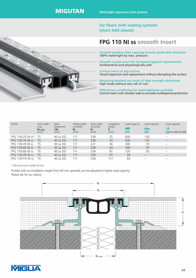
FPG 110 NI ss smooth Insert
for floors with coating systems(short AAS sheets)
Profile Joint width Total Visible width Total width Installation Load capacity Load capacity Load capacity max. Movement of profile of profile height bf max ∆bf bs bt h [mm] [mm] [mm] [mm] [mm] [kN] [kN] [kg/mm width of wheel] FPG 110/ 25 NI ss* 75 40 (± 20) 111 238 25 600 130 –FPG 110/ 35 NI ss 75 40 (± 20) 111 238 35 600 130 –FPG 110/ 45 NI ss 75 40 (± 20) 111 227 46 300 70 –FPG 110/ 60 NI ss 75 40 (± 20) 111 238 60 300 30 –FPG 110/ 80 NI ss 75 40 (± 20) 111 238 81 120 30 –FPG 110/ 95 NI ss 75 40 (± 20) 111 238 97 60 – –FPG 110/115 NI ss 75 40 (± 20) 111 238 117 60 – –
Striated stainless steel cappings ensures good skid resistance100% watertight by max. pressure Smooth central insert for increased hygienic requirements Antibacterial and physiologically safe
Central insert on top surfaceVisual inspection and replacement without disrupting the surface
Mounting brackets are made of high strength aluminiumHigh loads without any risk of rust
Official test certificates for watertightness availableCentral insert with double-web to provide multilayered protection
* Minimum joint width 50 mm
Profiles with an installation height from 60 mm upwards can be adjusted to higher load capacity. Please ask for our advice.
Watertight expansion joint systems

25
MIGUTan
b f max
b t
b s
h
bf max
bs
bt
h
FPL 85/27 NI
for floors with coating systems(short AAS sheets)
Profile Joint width Total Visible width Total width Installation Load capacity Load capacity max. Movement of profile of profile height bf max ∆bf bs bt h [mm] [mm] [mm] [mm] [mm] [kN] [kN] FPL 85/27 NI 50 40 (± 20) 85 214 27 300 70
Central insert on top surfaceVisual inspection and replacement without disrupting the surface
Stainless steel clip-on-cappings, made of spring steelEasy and cost saving assembly 100% watertight In connection with a coating system and a connection joint
MultiHole mounting bracket for secure fixing
Connection joint with connection joint filler profile AAP 110/23Proper and economical connection of the coating system
Watertight expansion joint systems

26
MIGUTan
b t
b s
h
b f max
b t
b s
h
b f max
b t
b s
h
b f max
b t
b s
h
b f max bf max
bs
bt
h
b t
b s
h
b f max
FPSG 68 ES smooth Insert
Watertight expansion joint systems
for floors with coating systems(short AAS sheets)
Profile Joint width Total Visible width Total width Installation Load capacity Load capacity Load capacity max. Movement of profile of profile height bf max ∆bf bs bt h [mm] [mm] [mm] [mm] [mm] [kN] [kN] [kg/mm width of wheel] FPSG 68/25 ES 25 10 (± 5) 68 218 25 600 130 12,5FPSG 68/30 ES 25 10 (± 5) 68 218 30 600 130 12,5FPSG 68/35 ES 25 10 (± 5) 68 218 35 600 130 12,5FPSG 68/40 ES 25 10 (± 5) 68 218 40 600 130 12,5
The system can be installed with and without connection joint.With connection joint and in connection with a coating system 100% watertightness is possible.Material: medium-affected: alloy 304 or 316 TiSub-construction: choosable
FPSG 68/35 ES withconnection joint
FPSG 68/35 ES withoutconnection joint
Intersections and end terminations can be fabricated according to requirements.The installation should be done by experienced companies.Other versions as well as individual advice on request.
Smooth central insert for increased hygienic requirementsAntibacterial and physiologically safe Central insert on top surfaceVisual inspection and replacement without disrupting the surface
100% watertight In connection with a coating system and a connection joint Solid metal designHigh load capacity (Heavy duty) up to 600 kN
Flexible use Sub-construction can be adapted acc. to requirements

27
MIGUTan
b t
b s
h
b f maxbf max
bs
bt
h
FP(G) ... /... NI XA MIGUTRIX
for flexible waterproofing slurry(MIGUTRIX sheets)
Profile Joint width Total Visible width Total width Installation Load capacity Load capacity Load capacity max. Movement of profile of profile height bf max ∆bf bs bt h [mm] [mm] [mm] [mm] [mm] [kN] [kN] [kg/mm width of wheel] FP 80/...NI XA 45 20 (± 10) 82 FPG 80/...NI XA 45 16 (± 8) 82 FP 90/...NI XA 60 40 (± 20) 95 FPG 90/...NI XA 60 20 (± 10) 95 FP 110/...NI XA 75 60 (± 30) 111 FPG 110/...NI XA 75 40 (± 20) 111 FP 130/...NI XA 100 90 (± 45) 133 FP 155/...NI XA 120 120 (± 30) 155
Installation example of series MIGUTrIX in combination with liquid membrane. Profile FPG 90/25 NI XA with fiber fabric bonded sheets (Installation on screed)
Striated stainless steel cappings ensures good skid resistance100% watertight by max. pressure Further development for liquid membranes/waterproofing slurry Fibre fabric bonded sheets for excellent bonding properties
Central insert on top surfaceVisual inspection and replacement without disrupting the surface
Official test certificates for watertightness availableCentral insert with double-web to provide multilayered protection Mounting brackets are made of high strength aluminiumHigh loads without any risk of rust
The connection of our fibre fabric bonded MIGUTrIX-sheets to the flexible waterproofing slurry / liquid membrane has to be tested for each application.
Watertight expansion joint systems
*For load capacity of the profile please refer to the corresponding profile
with short AAS sheets.

28
MIGUTan
b t
b s
b f max
h
bf max
bs
bt
h
Watertight expansion joint systems
FP…/…APF
MIGUTAN with structuralstainless steel cover plates
Profile Joint width Total Visible width Total width Installation Load capacity Load capacity Load capacity max. Movement of profile of profile height bf max ∆bf bs bt h [mm] [mm] [mm] [mm] [mm] [kN] [kN] [kg/mm width of wheel] FP 90/ 25 APF 60 40 (± 20) 98 222 28FP 90/ 35 APF 60 40 (± 20) 98 222 38FP 90/ 45 APF 60 40 (± 20) 98 211 49FP 90/ 60 APF 60 40 (± 20) 98 222 63FP 90/ 80 APF 60 40 (± 20) 98 222 84FP 90/ 95 APF 60 40 (± 20) 98 222 100FP 90/115 APF 60 40 (± 20) 98 222 120
Structural stainless steel cover plategood skid resistance acc. to official test certificate
Surface for special requirementsCaroplan, Bigpoint, Oval-Matt, Sand, Cross hatch
Mounting brackets are made of high strength aluminiumHigh loads without any risk of rust Special optical appearance For highest demands
All MIGUTAN systems can be supplied with the mentioned stainless steel cover plate; Technical data including load capacities can be supplied on request.
The cover plates are available for all types of insert, different load capacities and different kind of vehicles. Please ask for our assistance.

29
MIGUTan
b s
h
b f maxbf max
bs
h
Striated stainless steel cappings ensures good skid resistance100% watertight by max. pressure Central insert on top surfaceVisual inspection and replacement without disrupting the surface
Designed for additive floors / precast concrete slabsSlidable anchor rods for adjustable welding to the reinforcement Official test certificates for watertightness availableCentral insert with double-web to provide multilayered protection
Connection joint with connection joint filler profile AAP 50/20Proper and economical connection of the coating system
Watertight expansion joint systems
FP(G).../90 B NI anchor rods
for flush installation in concrete decks with coating systems (anchor rods / loop anchors)
Profile Fixing Joint width Total Visible width Installation Load capacity Load capacity Load capacity max. Movement of profile height bf max ∆bf bs h [mm] [mm] [mm] [mm] [kN] [kN] [kg/mm width of wheel] FP 80/90 B NI with anchor rods 21 (20 ± 10) 82 91 300 70 –FPG 80/90 B NI with anchor rods 21 (16 ± 8) 82 91 300 70 –FP 90/90 B NI with anchor rods 34 (40 ± 20) 95 91 300 70 –FPG 90/90 B NI with anchor rods 34 (20 ± 10) 95 91 300 70 –FP 110/90 B NI with anchor rods 50 (60 ± 30) 111 91 300 70 – FPG 110/90 B NI with anchor rods 50 (40 ± 20) 111 91 300 70 – FP 130/90 B NI with anchor rods 74 (90 ± 45) 133 91 120 35 –FP 155/90 B NI with anchor rods 94 (120 ± 60) 155 91 120 35 –

30
MIGUTan
b sb s
hh
b f maxb f max bf max
bs
h
Watertight expansion joint systems
Profile Fixing Joint width Total Visible width Installation Load capacity Load capacity Load capacity max. Movement of profile height bf max ∆bf bs h [mm] [mm] [mm] [mm] [kN] [kN] [kg/mm width of wheel] FP 80/90 B NI with loop anchors 21 20 (± 10) 82 100 600 130 6,5FPG 80/90 B NI with loop anchors 21 16 (± 8) 82 100 600 130 6,5FP 90/90 B NI with loop anchors 34 40 (± 20) 95 100 600 130 –FPG 90/90 B NI with loop anchors 34 40 (± 20) 95 100 600 130 4,3FP 110/90 B NI with loop anchors 50 60 (± 30) 111 100 600 130 –FPG 110/90 B NI with loop anchors 50 40 (± 20) 111 100 600 130 –FP 130/90 B NI with loop anchors 74 90 (± 45) 133 100 300 70 –FP 155/90 B NI with loop anchors 94 120 (± 60) 155 100 300 75 –
FP(G).../90 B NI loop anchors
for flush installation in concrete decks with coating systems (anchor rods / loop anchors)
Striated stainless steel cappings ensures good skid resistance100% watertight by max. pressure Central insert on top surfaceVisual inspection and replacement without disrupting the surface
Official test certificates for watertightness availableCentral insert with double-web to provide multilayered protection
Connection joint with connection joint filler profile AAP 50/20Proper and economical connection of the coating system
Designed for additive floors / precast concrete slabsSlidable loop anchors for adjustable welding to the reinforcement

31
MIGUTan
b s
h
b f max bf max
h
bs
FPI 145 B NI anchor rods
for flush installation in concrete decks with coating systems (anchor rods / loop anchors)
Profile Fixing Joint width Total Visible width Installation Load capacity Load capacity Load capacity max. Movement of profile height bf max ∆bf bs h [mm] [mm] [mm] [mm] [kN] [kN] [kg/mm width of wheel] FPI 145/90 B NI with anchor rods 118 (60 ± 30) 145 92 300 70 –
Striated stainless steel cappings ensures good skid resistance100% watertight by max. pressure Central insert on top surfaceVisual inspection and replacement without disrupting the surface
Connection joint with connection joint filler profile AAP 60/20Proper and economical connection of the coating system
Perfect sealingSpecial design without perforation of the sealing elements
Designed for additive floors / precast concrete slabsAnchor rods for welding to the reinforcement
Watertight expansion joint systems

32
MIGUTan
b f max
h
b s
bf max
bs
h
FPL 85/75 B NI anchor rods
for flush installation in concrete decks with coating systems (anchor rods / loop anchors)
Central insert on top surfaceVisual inspection and replacement without disrupting the surface
Connection joint with connection joint filler profile AAP 110/23 Proper and economical connection of the coating system 100% watertight In connection with a coating system and a connection joint Stainless steel clip-on-cappings, made of spring steel Easy and cost saving assembly Designed for additive floors / precast concrete slabsSlidable anchor rods for adjustable welding to the reinforcement
Watertight expansion joint systems
Profile Joint width Total Visible width Installation Load capacity Load capacity Load capacity max. Movement of profile height bf max ∆bf bs h [mm] [mm] [mm] [mm] [kN] [kN] [kg/mm width of wheel] FPL 85/75 B NI 40 40 (± 20) 85 75 300 70 –

33
MIGUTan
Watertight expansion joint systems
Notes

34
MIGUTan
1
23
4
5
7
9
1
2
3
4
5
8
10
9
10
Technical information
MIGUTAN systems 1 = Aluminium mounting bracket 2 = Spacer 3 = MIGUFLEX AAS sheets 4 = MIGUFLEX sealing insert 5 = Stainless steel capping 6 = Stainless steel cross recessed countersunk head screws 7 = Nylon washer 8 = Wedge flange 9 = Stable base (Solid floorspace) 10 = Non-shrinkage mortar (e.g. Epoxy mortar, PPC-mortar), suitable for the given load
The system long AAS sheets
FPI-System withlong AAS sheets
FP-System withlong AAS sheets
Application and installation instructions will be provided on request. Please contact us. As an alternative you can download it from our website www.migua.com

35
MIGUTan
1
2
4
5
1
2
34
5
6
1
2
34
5
6
9
10
9
10
8
9
10
Technical information
The system short AAS sheets
FP-System withshort AAS sheets
FPL-System
FPI-System withshort AAS sheets

36
MIGUTan
Technical information
Transitions FP 90 Examples

37
MIGUTan Technical information
Transitions FP 90 Examples

38
MIGUTan
Technical information
Central Insert FPG 80
Central Insert FP 80
Central Insert FP 130
Central Insert FPG 90
Central Insert FP 90
Central Insert FP 155
Central Insert FPG110
Central Insert FP110
Available Inserts FP / FPG

39
MIGUTan
Example FP 90/80 NI
Example FP 90/25 NI
Example FP 90/90 B NI
Technical information
Profile connections

40
MIGUTan
C leftC right D right
E rightD left E left
F leftF right
Technical information
Terminations / Intersections
A 2A 1
G 1
B

41
MIGUTan
H 1 right H 1 left
H 2 leftH 2 right I 1 right
I 2 rightI 1 left I 2 left
J 1 leftJ 1 right J 2 right
Technical information
Terminations / Intersections
G 2

42
MIGUTan
K 1 rightJ 2 left K 1 left
K 2 leftK 2 right L right
ML left N right
O rightN left O left
Technical information
Terminations / Intersections

43
MIGUTan
P left(Angle supplied by others)
P right(Angle supplied by others)
Q rightP 1 left(Angle supplied by others)
P 1 right(Angle supplied by others)
R
Q left
S T right
UT left U 1
Technical information
Terminations / Intersections

44
MIGUTan
W right
W left W 1 leftW 1 right
V leftV right
W 2 leftW 2 right W 3 right
X rightW 3 left X left
Technical information
Terminations / Intersections

45
MIGUTan
X 1 leftX 1 right Y
Z
Upstand, short AAS sheets
Flat angle, short AAS sheets T-Piece, long AAS sheets Cross, short AAS sheets
Upstand, long AAS sheets Slope end
The illustrated terminations/intersections A–Z are a selection of possible solutions only. We are able to fabricate watertight terminations/intersections for each joint run.
W right
W 1 left
W 3 right
X left
Technical information
Terminations / Intersections
Standard Intersections

46
MIGUTan
�
��
��
����
�
��
��
����
h2
h
10
bs
bt
E 5-Version: FPI 145/40 NI E5
Column-/Wall-Connections FPI - with long AAS sheetsfor bituminous layer
Technical information
Transition from floor/floor to floor/wall for columns
Please consider the following using version E2 or E3:
If the joint is adjacent to a column or a wall, two prefabricatedhorizontal intersections will be required at each edge (see drawing). This ensures that the profile covers the centreline of the joint in the area exposed to traffic. Such intersections, however, are not necessary, if the distance between column/wall and the centreline of the joint is approx. 60 mm. In this case, it is only necessary to prefabricate a welded connection within the AAS-sheets at each edge of the column/wall.

47
MIGUTan
�
�
��
�
�
��
�
�
��
��
�
�
��
��
bs
91
50
bt
bs
58 m
m
bt
Technical information
E 3-Version: FPI 145/90 B NI E 3
Column-/Wall-Connections FPI - with short AAS sheetsfor floors with coating systems
E 4-Version: FPI 145/28 NI E 4

48
MIGUTan
�
�
�� h2
bt
bs
Corner Version E 2 E 3 E 4 E 5 Profile bs bt bs bt bs bt bs bt FP(G) 80 NI 96 159 - - 56 119 55 118FP(G) 90 NI 109 172 - - 69 132 68 131FP(G) 110 NI 125 188 - - 85 148 84 147FP 130 NI 147 210 - - 107 170 106 169FP 155 NI 169 232 - - 129 192 128 191 FP(G) 80/90 B NI - - 92 223 56 - - -FP(G) 90/90 B NI - - 105 236 69 - - -FP(G) 110/90 B NI - - 121 252 85 - - -FP 130 B NI - - 143 264 129 - - -FP 155 B NI - - 165 296 107 - - - FPI 145/28 NI 159 206 - - 101 148 - -FPI 145/40 NI 159 206 - - 101 148 99 146FPI 145/60 NI 159 224 - - 101 166 99 164 FPI 145/90 B NI - - 155 302 101 249 - - FPL 85/27 NI - - - - 69 134 - - FPL 85/75 B NI - - 98 144 69 173 - -
Technical information
Column-/Wall-Connections FPI - with short AAS sheetsfor floors with coating systems
E 4-Version: FPI 145/90 B NI E 4

49
MIGUTan
FP 90/45 Ni E2
bt
bs
b f max
h
bf max
h
bs
bt
FP 90/45 NI E 2
b tb s
h
b f max
h 2
bf max
h
bs
bt
FP 90/45 NI E 5
200
mm
150
min
.
The illustrated vertical cover flashing is to be supplied by others.
Technical information
E 5-Version:for Column-/Wall-Connectionsin connection with the profiles
- FP(G) 80 NI- FP(G) 90 NI- FP(G) 110 NI- FP 130 NI- FP 155 NI
E 2-Version: or Column-/Wall-Connectionsin connection with the profiles
- FP(G) 80 NI- FP(G) 90 NI- FP(G) 110 NI- FP 130 NI- FP 155 NI
Column-/Wall-ConnectionsFP - with long AAS sheetsfor bituminous layer

50
MIGUTan
b tb s
h
b f max
h 2
b tb s
h
b f max bf max
h
bs
bt
FP 90/90 B NI E 3
FP 90/90 B NI E 4 bf max
hbs
bt
58 m
m
Technical information
E 3 and E 4-Versions: for Column-/Wall-Connectionsin connection with the profiles
- FP(G) 80/90 B NI- FP(G) 90/90 B NI- FP(G) 110/90 B NI- FP 130/90 B NI- FP 155/90 B NI
Column-/Wall-Connections FP - with short AAS sheetsfor floors with coating systems

51
MIGUTan
b t
b s
h
b f max
h 2
FP 90/25 NI E 4 bf max
h
bs
bt
58 m
m
Technical information
E 4-Version: for Column-/Wall-Connectionsin connection with the profiles
- FP(G) 80 NI- FP(G) 90 NI- FP(G) 110 NI- FP 130 NI- FP 155 NI
Transition from floor/floor to floor/wall for columns
Please consider the following using version E2 or E3:
If the joint is adjacent to a column or a wall, two prefabricatedhorizontal intersections will be required at each edge (see drawing). This ensures that the profile covers the centreline of the joint in the area exposed to traffic.
Such intersections, however, are not necessary, if the distance between column/wall and the centreline of the joint is approx. 40 mm. In this case, it is only necessary to prefabricate a welded connection within the AAS-sheets at each edge of the column/wall.
Column-/Wall-Connections FP - with short AAS sheetsfor floors with coating systems
52
MIGUTan
b t
b s
h
b f max bf max
bs
bt
FP 90/45 NI AP 800
FP 110/60 NI APG 110/3
Technical information
Installation examples Cover plates
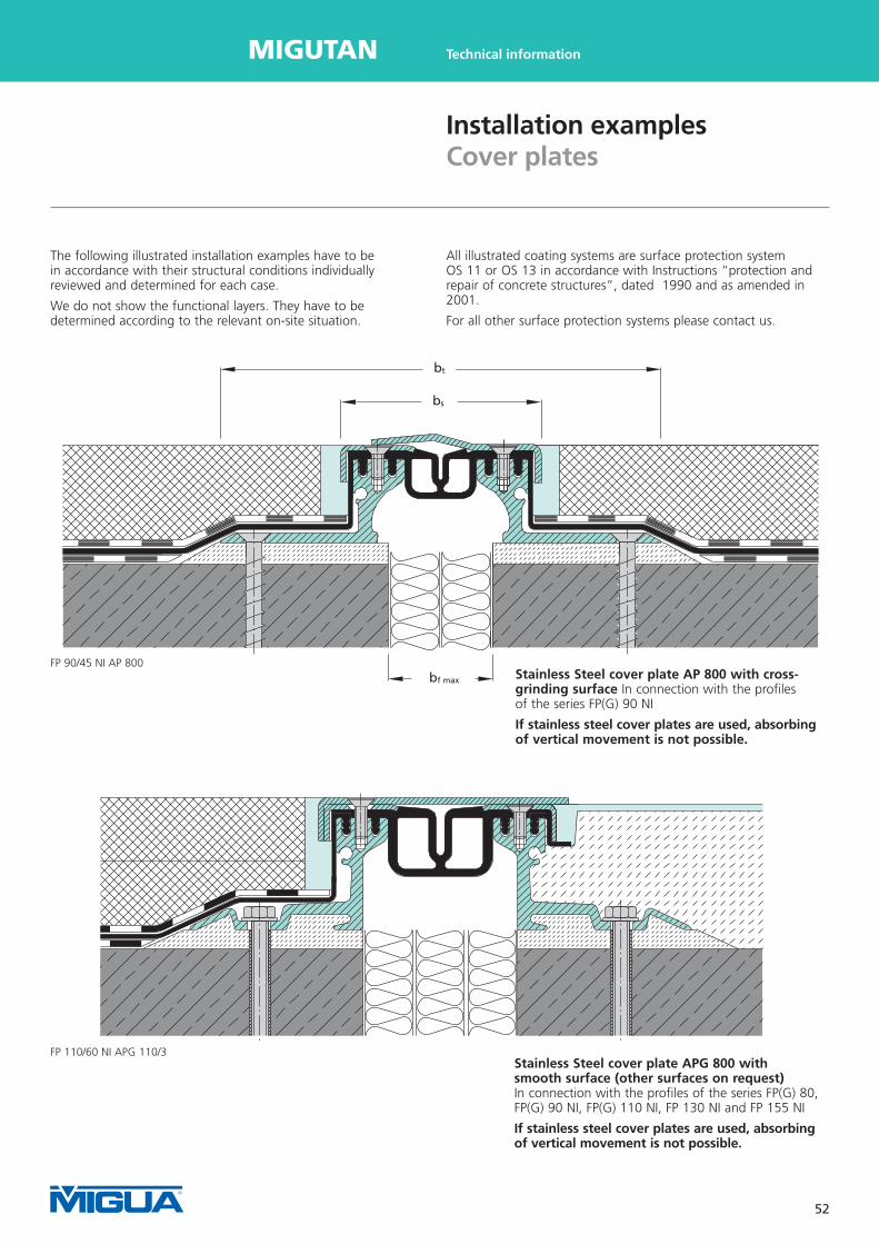
The following illustrated installation examples have to bein accordance with their structural conditions individuallyreviewed and determined for each case. We do not show the functional layers. They have to be determined according to the relevant on-site situation.
All illustrated coating systems are surface protection system OS 11 or OS 13 in accordance with Instructions “protection and repair of concrete structures”, dated 1990 and as amended in 2001. For all other surface protection systems please contact us.
Stainless Steel cover plate APG 800 with smooth surface (other surfaces on request)In connection with the profiles of the series FP(G) 80, FP(G) 90 NI, FP(G) 110 NI, FP 130 NI and FP 155 NI If stainless steel cover plates are used, absorbing of vertical movement is not possible.
Stainless Steel cover plate AP 800 with cross- grinding surface In connection with the profiles of the series FP(G) 90 NI If stainless steel cover plates are used, absorbing of vertical movement is not possible.

53
MIGUTan
Examples: FP 90/25 NI with “toothed” cover plate APS
Example with APS cover plate: FPG 90/35 NI APS
Technical information
Installation examples Cover plates

54
MIGUTan
Installation Example FP 90/25 NI: MIGUTAN expansion joint system with short AAS sheets on concrete slab (no recess)
Installation Example FP 80/25 NI: MIGUTAN expansion joint system with short AAS sheetsIn connection with hardened paving or asphalt without waterproofing layer
Installation Example FP 90/25 NI: MIGUTAN expansion joint system with short AAS sheetsIn connection with hardened paving or asphalt without waterproofing layer
Technical information
Installation examples Small heights
Watertight epoxy or PCC mortar
Watertight epoxy or PCC mortar

55
MIGUTan
FP 90 SB Ni k.F.
bt
bs
b f max
h
bf max
h
bs
bt
Installation Example: MIGUTAN expansion joint system with long AAS sheets installed below earth
Installation Example: MIGUTAN expansion joint system with long AAS sheetsand aluminium plates, prefabricated in our factory for large joints
Technical information
Installation examples Small heights
Slope for drainageSlope for drainage

56
MIGUTan
Installation Example: MIGUTAN expansion joint system with long AAS sheets for large installation heights
Installation Example: MIGUTAN expansion joint system with long AAS sheets for large installation heights
Technical information
Installation examples Large height

57
MIGUTan Profilkombinationen
Installation Example: MIGUTAN expansion joint system with short AAS sheets in connection with additive floors / precast concrete slabs
Technical information
Installation examples Insitu - concrete

58
MIGUTan
Profilkombinationen
Installation Example FPG 90/100 NI XA: MIGUTAN expansion joint system with MIGUTrIX fibre fabric bonded sheetsin connection with liquid membranes / flexible waterproofing slurry
Technical information
Installation examples Various
Installation Example: MIGUTAN expansion joint system with long AAS sheets in connection with thermal insulation

59
MIGUTan Profilkombinationen
bt
bs
b f max
h
bf max
h
bs
bt
Technical information
Installation examples Various
Installation Example: MIGUTAN expansion joint system with long AAS sheets and special wall connection
Installation Example FP 90/25 NI: MIGUTAN expansion joint system with short sheetsConnection joint filled with flexible coating

60
MIGUTan
Einbauvorschlag 13 - FP 160/100 Ni l.F. mit APG
Installation Example: Combined MIGUTAN expansion joint system FP …/45 NI with long AAS sheets and FP …/25 NI with short AAS sheets with APG cover plate for large joint width
Installation Example FP 160/100 NI: MIGUTAN expansion joint system with APG cover plate for large joint width and big movement capacity (105 mm (+ 65 – 40 mm))
Technical information
Installation examples Large joint width / big movement

61
MIGUTan
Technical information
Installation examples Large joint width / big movement
Notes

62
MIGUTan
Profilkombinationen
Illustrations of applications
Multi storey car park Citti Park, Lübeck, Germany – FP90
Municipal indoor pool, Plauen, Germany
Multi storey car park at main railway station, Berlin, Germany
Shopping Mall Citti Park, Kiel, Germany – FS 110; ESF 10; FS 75; STD 100
Stadium BayArena, Leverkusen, Germany – FP 90 Airport, Nürnberg, Germany – FP 90; FP 115
Multi storey car park Beusselstreet, Berlin, Germany

63
MIGUTan Profilkombinationen
Illustrations of applications
Airport Cologne-Bonn, Germany – FP 90
Multi storey car park Weiterstadt, Germany – FP 90
Spreebogenpark, Berlin, Germany
Shopping Mall Elbe Park, Dresden, Germany
Lessing Bridge, Berlin, Germany
Multi storey car park, Lübeck, Germany
FMZ Brunnenstraße, Berlin, Germany
State Fair, Stuttgart, Germany – FPI 145
Bridge Renovation, Ellenburg, Germany Multi storey car park Erfurt Stadium, Germany

64
MIGUTan
Profilkombinationen
Illustrations of applications
Multi storey car park, Chemnitz, Germany
Multi storey car park Toyota, Cottbus, Germany
Car park at Shopping Mall, Dresden, Germany
Multi storey car park Weiterstadt, Germany – FP 115

65
MIGUTan Profilkombinationen
Illustrations of applications
Konsum, Leipzig, Germany – FP 90/25 Multi storey car park, Berlin-Marzahn, Germany
Multi storey car park, Annaberg, Germany – FP 90
Bus Service Station, Mainz, Germany – FP 90
New Airport BBI, Berlin, Germany – FP 90 BNI Beecken , Germany – FP 90 BNI RA Tübingen, Germany – FP 90
Railway station Adlershof, Berlin, Germany – FP 90

66
MIGUTan
MIGUa
MIGUA Headquarters in Wuelfrath
At a glance
MIGUA. Market leader in Europe for more than 50 years.
MIGUA is completely focused on expansion joint systems. Leading
architects, designers and general contractors specify our products for
national and international projects. We will gladly provide you with
a list of references, on request. MIGUA expansion joint systems are
used from Abu Dhabi to Zurich providing protection, functionality
and architectural excellence on a permanent basis.
They are used in many different building types, e.g. shopping
malls, airports, exhibition halls, hospitals, industrial plants, storage
facilities, car parks and pedestrian bridges. It is our passion to
be innovative, to supply perfect quality and to develop solutions
according to customer requirements.
Technology. Innovative from experience.
Competence does not appear by chance. More than 10 million metres
of MIGUA movement joint systems have, over decades, been installed
worldwide to the satisfaction of architects, designers, builders and
owners. We are leaders in technological development in Europe as
witnessed by numerous patents and test certificates.
MIGUA engineers are, on an ongoing basis, designing and developing
new profiles with enhanced characteristics which lead to time and cost
saving installations. Through the use of special materials safety features
are improved and stringent performance tests are conducted on all
new products.
Quality. Made in Germany.
MIGUA products combine optimum solutions with excellence in
design, high quality materials and safety features which are supported
by our standard warranties. Quality makes the pre-condition for
product safety. That is why MIGUA develop and manufacture
in Germany. Only products on the highest standard achieve the
necessary durability and allow required warranties.
Due to this reason MIGUA is able to offer such warranties.
Beyond the technical quality of our products the main target of
the MIGUA quality management is the utmost satisfaction of our
customers. Each operation and work step is described and will be
recorded. From the first idea through research and development up
to successful market launch. Just this makes MIGUA successful.
LOAD CAPACITy FS 110
FATIGUE LOADING
SkID rESISTANCE
LOAD CAPACITy / WATErTIGHTNESS

67
MIGUTanMIGUa At a glance
Solutions. Which work.
By ensuring the technical quality of our products MIGUA can attain
its primary goal of complete customer satisfaction. We understand
the expectations of our customers, and how to exceed them.
This requires a strong commitment for special requests and solutions.
MIGUA is prepared for it – from the beginning. We are always
available for your questions or giving advice to find the solution our
customers need. Our products are supported by a national network
of technical experts, close cooperation with our world-wide partners
and an experienced international export team.
MIGUA offers the perfect solution for your project.
Contact

68
MIGUTan FUGENSYSTEME
MIGUA offers a comprehensive product portfolio of expansion joint covers and systems with outstanding features.
Quality. Made in Germany.
Postal address: PO Box 1260 · 42479 WuelfrathHeadquarters: Dieselstr. 20 · 42489 Wuelfrath
Phone +49 2058 774-0 Fax +49 2058 774-48
[email protected] www.migua.com
FUGENSySTEME GMBH & CO. kG
Subj
ect
to t
echn
ical
cha
nge.
11
/201
1 -
5000
GB
MIGUTRanS
Heavy duty expansion joint systems
MIGUTan
Watertight expansion joint systems for traffic
MIGUPREn
Watertight expansion joint systems for roofs
MIGUMaX
Earthquake resistant expansion joint systems
MIGUTEC
Expansion joint profiles
Increasing architectural requirements as well as new construction materials and processes demand optimized expansion joint systems. For this reason, MIGUA is your experienced partner since we offer more than 600 different profiles for a wide range of applications.
Our product range covers 5 application orientated product groups as detailed below. In addition to standard profiles our r&D engineers provide highly sophisticated solutions for special or non-standard applications.
MIGUA provides solutions for extraordinary challenges.


