

WATER SYSTEMS ON THE FARM
D 0 YOU plan to install a pressure water system on your farm? Do you know what factors to consider in selecting a pump? Have you an adequate water supply? The following questions are discussed in this bulletin to give you some answers you may need:
I) Where can you get the water?
t) How much water will you need?
~ What types of water supply systems are there?
• What type of pump should you select?
~ What factors should you consider in selecting a pump?
~ What are some typical pump installations?
, t) What size and type tank do you need?
~ What is (:l typical pipe layout within a house?
~ What are the specifications of an adequate pump pit?
I) Where Can You Get the Water? Electrically operated water systems
may pump water from (1) wells, (2) springs, and (3) cisterns. Regardless of the source, the water supply should be pure, dependable, and sufficient to provide water for all farm uses.
Wells are classified according to the method of construction. There are (1) drilled, (2) driven, (3) bored, and (4) dug wells. All surface and polluted water should be prevented from entering the well.
All wells should be located approximately 100 feet from any contaminating source.
t) How Much Water Will You Need? The amount of water required per
day depends on the number and kind of livestock, the number of persons in the family, and the number of mo4ern conveniences on the farm that use large amounts of water.
Do not think in terms of the amount of water normally carried by hand, for this may lead to the purchase of a pump with insufficient capacity.
The water required on any farm can be estimated by using table 1. This information is necessary to determine the pump capacity needed (see page 5).

WATER SYSTEMS AND SEWAGE DISPOSAL 3
TABLE 1. WATER REQUIREMENTS Gallons per day
Each member of family.................................... 35 Each horse ..................................................................... 10 Each cow ...................... :................................................. 25 Each hog ............. .......................................................... 2 Each sheep .................................................................. 1 1/2
100 chickens ............................................................... 5 Gallons
per hour
112 inch hose with nozzle ............................... 200 % inch hose with nozzle ........................... 275-300 Lawn sprinkler ........................................................ 200
Example of Water Used Daily Gallons per day
4 persons at 35 gallons.............................. 140 10 cows at 25 gallons .................................... 250 2 horses at 10 gallons................................. 20
50 hogs at 2 gallons ......................................... 100 200 chickens at 5 gallons per 100
chickens ......................................................... 10
TOTAL daily requirement for home and livestock ......... ............................ 520 gallons
11'\. What Types of Water Supply F:f Systems Are There?
The two main types of systems used to supply water under pressure are the gravity and the hydropneumatic.
The Gravity System. In this system, water is pumped to a storage tank of such elevation that water can flow to all outlets by gravity.
Hydropneumatic or Pressure Tank System. In this system, water and air are pumped into an airtight steel tank. The air that occupies the top part of the tank is compressed when either more air or more water is pumped into it. The pressure exerted by the compressed air forces water from the tank through the pipes to the outlets.
t.. What Type of Pump Should You . tif Select?
There are two general types of pumps, depending upon the depth from which they are designed to lift water. Hence they are known as (1) shallow well pumps and (2) deep well pumps.
Shallow well pumps are used when the suction lift is not more than 22
feet. Suction lift is the vertical distance from pump to water level, plus the friction loss in suction piping.
Deep well pumps are used where the depth to water is greater than 22 feet. These pumps are classified as (1) piston or plunger pumps and (2) ejector type pumps.
In principle of operation the piston or plunger pump is identical to that of the deep well hand pump, except for the pump head.
The ejector type pump consists of a vertical centrifugal pump and motor placed aboveground and connected by pipes to an ejector (a jet) in the well. This jet acts as a auxiliary pump, boosting the water to within suction distance of the centrifugal pump.
Unlike other deep well pumps, the ejector pump has the advantage of only one moving part and is exceptionally quiet in operation. It is not necessary to install it directly over the well; therefore the pump may be installed in the basement and pipes run underground
FIG. 1. Shallow well pump. 1. Suction pipe connection. 2. Discharge pipe connection.

4 EXTENSION BULLETIN 247
Deep well pumping head
C;:linder lower Valve
Strainer·--"+-!
FIG. 2. Piston or plunger type pump for deep well operation
to the well. The ejector pump is ordinarily most efficient for lifts not exceeding 60 feet, and where capacity is not too large. The maximum depth recommended for this pump installation is 80 feet. If it operates against a very high pressure head no water will be delivered to the pressure tank.
IIIII
Sucfion plpe
FIG. 3. Gross section of deep well jet centrifugal pump

WATER SYSTEMS AND SEW AGE DISPOSAL 5
~ What Factors Should You Con-I'( sider in Selecting a Pump?
The factors to consider are friction in pipes and rated capacity of pump.
Friction. When water passes through . a pipe line, a certain amount of friction causes resistance to the flow of water. The effect of this resistance is to increase the vertical height or "head" against which the pump must work and still produce an adequate flow of water at faucets or other points of discharge.
The actual resistance of a pipe line depends upon diameter of pipe, length of pipe, smoothness or roughness, number of bends, and rate of flow.
Table 2 shows, in feet and in pounds pressure, the loss of head due to friction per 100 feet of ordinary pipe, when discharging given quantities of water. A rule of thumb to follow regarding pipe size is: Do not install underground a pipe less than llf4 inches in diameter.
EXAMPLE: What pressure in pounds or feet of head will be required to overcome friction if the flow is 5 gallons per minute through a 11J.i-inch pipe 300 feet long, having three 90-degree elbows?
From table 2, friction loss in three 90-degree
elbows js equal to 24 feet of l 1.4-inch pipe (3 x 8) and friction loss in 100 feet of 11J.iinch pipe (5 gallons per minute flow) is .84 feet of head or .36 pounds pressure. The fric· !ion Joss for 300 feet of pipe and three SOdegree elbows would be
324 X 84 --- = 2..72 it. of head 100
324 X 36 --- - 1.17 pounds pressure
100
Capacity of Pump. The capacity or size of pump needed depends upon the amount of water required each day, as explained on page 3. A good rule to follow in determining pump capacity is to figure a two hour running time for the pump each day. Thus the requirements for the sample farm would be 520 gallons divided by two or a 260-gallon per hour capacity pump.
It is important to measure the yield of water from the well to see if it will furnish plenty of water for the pump when operating at maximum capacity. If the yield is small a reservoir may be required to accumulate the necessary water supply. Another alternative would be to use a pump of small capacity in conjunction with a large pressure or gravity tank.
Table 2. Pipe Friction per 100 Feet of Ordlncuy Iron Pipe Expressed as Feet and as Pounds for Various Rates of Flow
Size of pipe
Flow gal-ion per
\12 inch %inch linch liJ.i inch l\12 inch 2inch
minute ft. lbs. ft. lbs. ft. lbs. ft. lbs. ft. ibs. ft. lbs.
2 ...................................... 1.4 3.2 1.9 .82 3 ......................................... 15.8 6.85 4.1 1.78 1.26 .55 4 ........................................ 27.0 11.7 7.0 3.04 2.14 .93 .57 .25 .26 .11 5 ....... ............................ 41.0 17.8 10.5 4.56 3.25 1.41 .84 .36 .40 .17 6 ........................ , ............... 14.7 6.36 4.55 1.97 1.20 .52 .56 .24 .20 .086 8 ......................................... 25.0 10.8 7.8 3.38 2.03 .88 .95 .41 .33 .143
10 ....................................... 38.0 16.4 11.7 5.07 3.05 1.32 1.43 .62 .50 .216 12 ........................................ 16.4 7.10 4.3 1.86 2.01 .87 .70 .303 14 ........................................ 22.0 9.52 5.7 2.46 2.68 1.16 .94 .406 16 ........................................ 28.0 12.10 7.3 3.16 3.41 1.47 1.20 .520 18 ......................................... 9.1 3.94 4.24 1.83 1.49 .645
Feet of pipe equivalent to a 90-degree elbow 5 6 6 8 8 8
NOTE: 1 pound pressure - 2.31 feet water column. 1 foot water column = .43 pound pressure.
It is necessary to elevate a gravity lank 92.4 feet to supply the same pressure at an outlet as can be supplied by a pressure tank when the pressure is at 40 pounds per square inch.

6 EXTENSION BULLETIN 247
~ What Are Some Typical Pump Installations?
TYPICAL SHALLOW WELL INSTALLATIONS
Fig. 4. Pump and tank at point of discharge
Pipe
This is an installation where the vertical lift "X" plus the friction loss in the suction pipe does not exceed the total suction lift of the pump.
Fig. 5. Pump at source of supply and tank at point of discharge
Pif
With this type of installation, the pump operates under higher pressure than shown on the pressure
gauge in the tank. This extra pressure is equal to the vertical distance plus friction loss in the discharge pipe from pump to tank.

Z·
WATER SYSTEMS AND SEWAGE DISPOSAL 7
TYPICAL EJECTOR PUMP INSTALLATIONS
House
Pressure lcmk
Fig. 6. Pump located ·over well
One of the most satisfactory installations of a deep well ejector pump water system is with the well located just out-side the foundation wall of the house so that the pump room really becomes part of the basement. This
gives easy access to the pump, tank, motor, and all controls in any kind of weather. However, pump and tank can be in a pit located at some distance from the house.
Fig. 7. Pump located away from well
Jet pumps need not be placed directly over the well, but may be set
Supply pipe-
a reasonable distance away at any desired and convenient location. The horizontal pipe lines should slope upward toward the pump to prevent air pockets. A small pit at the well is necessary for installing the ejector.
Jef The size of pressure and suction pipes should be checked carefully when the pump is installed at a distance from the well.

8 EXTENSION BULLETIN 247
TYPICAL PISTON OR PLUNGER PUMP INSTALLATIONS
Fig. 8. Pump and tank near source
When the yvell is not at' the point of discharge, the pump and tank may be installed in a frost-proof pit or in a well house aboveground. A lighted 40 watt bulb will usually prevent frost damage on cold nights. Always leave an opening in the ceiling of the pit or pump house to remove rods for inspection. •
To conserve space in the pit. the pressure tank may be installed horizontally and buried underground with the end extending into the pit so gauges, controls, etc., may be attached.
Fig. 9. Pump near sourcetank near point of discharge
Lowe sf wafer level
Cyllnder
Where the pump and tank are installed some distance apart, it is advisable to install a check valve and air chamber in the discharge line near the pump to reduce the pulsations from the pump.

WATER SYSTEMS AND SEWAGE DISPOSAL 9
L\.. What Size and Type Tank Do 'f You Need?
Gravity Tanks. The size of storage tank for a gravity system depends upon the water needed, the amount of water at the source, and the interval between pumpings. It is advisable to construct a tank large enough to handle sprinkling of the lawn and fire protection. A minimum size should hold a week's supply.
The tanks located in buildings are usually wood or steel, while concrete tanks are placed underground on hill locations.
Pressure Tanks. A pressure tank performs two distinct functions in the operation of an automatic water system. First, it provides a storage place for water, so that the pump is not required to operate each time a small amount of water is used, thus avoiding ex'ces-
In lei
42 Gallon tank
Compressed ctir
Reservoir of wetter f'or emergency use
Ouflet
FIG. 10. Hydropneumatic or pressure tank
sive starting-and-stopping wear on the motor. Second, the pressure tank provides the necessary air pressure for operating the pressure system. When water is first pumped into the pressure tank, the air is compressed until the air pressure reaches 40 pounds per square inch, which means the tank is two-thirds filled with water and onethird filled with air. This compressed air constantly exerts a pressure in an effort to expand to its normal volume, and it is this compressed air that provides the pressure for the water system.
The pressure switch is set to start the pump operating when the pressure in the tank drops to 20 pounds per square inch, and stop when the pressure reaches 40 pounds.
At 20 pounds pressure the tank is two-fifths filled with water, and threefifths filled with air. Thus only onefifth of the rated capacity of the tank may be drawn before the pump will start.
It is recommended that a tank having an 8- to 10-gallon active water supply be used. Thus a 42-gallon pressure tank has been accepted as standard for most farm automatic systems. Larger sizes are needed in specific cases such as large dairy farms where water demand is unusual. However, it is sometimes more economical to construct a storage tank in the barn for dairy purposes than to increase the' size of the pressure tank and pump for the entire system.
~ What Is a Typical Pipe Layout ltf within a House?
In planning a water system for the home, it is advisable to make a tentative layout of the location and types of plumbing facilities desired.
The location of the water system determines where the starting point will be. The water supply line should be piped to the kitchen first where most water is needed and where the first

ra t-=D
FIG. 11. Typical pipe layout within a house

WATER SYSTEMS AND SEWAGE DISPOSAL 11
piece of equipment is usually installed. Hot running water may be supplied by installing a hot water tank with a coil in the furnace. When the furnace is not operated, the hot water tank may be heated by electricity, bottle gas, or kerosene.
It is preferable to locate the bathroom directly over the kitchen from the standpoint of piping, because the hot and cold pipes may be continued instead of running another series from the basement. This also consolidates the waste disposal system. Shut-off valves should be used at every branch of the water supply line.
f... What Are the Specifications of V an Adequate Pump Pit?
Aboveground installation of pumping and pressure equipment is to be pre
The accompanying diagram of a pump pit is presented here because such installations are widely used in spite of the possible dangers that have been suggested by sanitation engineers. Proper construction is the best protection against pit troubles.
It is important that both ventilation and drainage be adequate. Two vent pipes are desirable for ventilation, one for top ventilation and another extending down to within a foot of the floor.
Where the natural ground line falls away from the pit, the floor drain should lead to the surface, thereby providing a reliable outlet even for large amounts of water. If a surface drain is impossible, a gravel sump such as. that shown in the diagram must be provided to take care of seepage. Under no circumstances should the drain be connected with the house sewer.
~ 'Pump and 't!..,
mofor
~i ¢ bar3 8"0.C.hofh
ways Nofe- Floor drain should never be connecfed fo fhe sewer lr'ne. Storage fr;rn/r for deep well pump
mcry be placed CIS shown otf-®
ferred for reasons of better sanitation. However, the pump pit has been widely used on farms because it facilitates protection from freezing in winter and permits a colder water supply in summer. Farmers considering such installation should investigate local and Minnesota State Board of Health regulations to make sure they will not come into conflict with ordinances governing the sale of milk and other products. Objections to pump pits are based upon possible dangers of contamination of the water supply by surface water through poor drainage, backing up of drains during floods, and bad sanitation in the underground pit. FIG. 12. Suggested construction of pump pit

12 EXTENSION BULLETIN 247
SEWAGE DISPOSAL ON THE FARM t What are the necessary parts of a good farm sewage dis
posal system?
• What size septic tank is needed? ·
t) Where should a septic tank be located?.
t What types of septic tanks are there and how are they installed?
• What are the recommended sizes and grades for the house sewer and outlet sewer?
~ What type of disposal field can be used for effluent after it has passed through the septic tank?
t) What maintenance is necessary to insure good operation of a septic tank?
11\. What Are the Necessary Parts of If a Good Farm Sewage Disposal
System? There are four distinct parts to a
sewage disposal system, each one of which is equally important. They are:
(1) The house sewer which carries wastes from the house to the septic tank.
(2) The septic tank in which sewage treatment begins. Much of the solid matter in the sewage entering the septic tank is broken up into gases, liquids, and mineral particles through bacterial action. In a well-built system the gases pass off readily without offense, liquids flow out of the septic tank, and the heavier solids called "sludge" settle to the bottom. A scum which forms over the top of the sewage in the tank aids in decomposition.
(3) The outlet sewer which carries sewage liquids, commonly called effluent, from the septic tank to
the tile disposal lines or dry well.
( 4) The various types of disposal fields which handle the discharge from the septic tank.
L\. What Size Septic Tank Is 'f N~eded?
A large enough tank is the most important part of any sewage disposal system. A tank of 500-gallon capacity is the minimum size recommended, regardless of the size of the family. If the tank is to be located where additional length and depth will cost very little more, a minimum size of 675 gallons is suggested. Any added cost in installing an extra-size tank will be repaid many times in the next 20 years.
The septic tank should hold all inflow for a period long enough to allow bacterial action to liquefy the sewage. If the bacterial action is complete, only clear liquid will flpw through the outlet, and any adequate disposal system will handle this discharge for years without trouble. However, if a small

WATER SYSTEMS AND SEWAGE DISPOSAL 13
"trick-size" tank is used, where sludge and raw sewage are forced through the outlet, there is no type of disposal field, even in coarse sand, that will work satisfactorily for a very long period.
The depth and length are the most important dimensions of a septic tank. These dimensions determine the probability of raw sewage and accumulated sludge being carried out of the tank and deposited in the disposal field.
There are definite minimum dimensions necessary for successful operation of the tank, regardless of the capacity needed. In a large one-chamber tank a minimum depth of 6 feet is recommended. Only about 4 feet can be used to calculate capacity because about 1 foot is lost by the outlet being placed 1 foot below the cover and another foot is subtracted to allow for sludge accumulation in the bottom. This leaves the incoming sewage a distance of 4 feet from the accumulated sludge line. If the distance were less, the velocity of inflow would tend to scour the sludge in the bottom up into suspension and carry part of it past the outlet.
A minimum length of 6 feet is suggested to allow suspended sludge to settle out inside the tank instead of flowing out to choke the absorption field. · Let's analyze the need for a minimum capacity of 500 gallons for any farm installation of a septic tank. All sewage should be held within the tank for 48 hours. Each member of the family requires a tank capacity of 35 gallons per day (24 hours). For a 48-hour period a tank capacity of 70 gallons (35 X 2) per member of the family is needed.
When estimating the number of persons that will use the system, be sure to include large amounts of company and all hired help. A safe estimate for minimum numbers would be 4 for the family, 1 for company, and 1 for hired help, a total of 6. Therefore, 6 X 70 equals 420 gallons capacity needed
to hold sewage for 48 hours. To this has to be added the volume necessary to hold 1 foot of accumulated sludge, because when sludge builds up it cuts the capacity of the tank. The actual capacity in gallons needed to hold sludge varies with the cross-sectional area of the tank, but it will approximate 100 gallons. Adding this to 420 gives a total of 520 gallons.
This total capacity has to be below the outflow elevation because no sewage can be stored above the outlet. Rather than design each tank individually, we recommend a family-size tank (figure 13) even though there are only two or three persons in the family. On the other hand, this size tank safely accommodates up to nine or ten persons.
!.\. Where Should a Septic Tank rtf Be Located?
The location of the septic tank depends upon the topography of . the ground. If the ground is level it is best to locate the tank close to the house to get the necessary minimum grades in both house sewer and outlet sewer. The tank may be placed adjacent to the foundation wall but should not be a part of the wall.
If grades can be easily obtained, the tank is normally located not more than 25 feet from the house.
In heavy flat land the tank should be placed with about one foot of dirt over the cover. The basement cannot be drained by gravity under these circumstances. A sump pump can be installed in a pit in the basement to pump basement wastes into the house sewer line, from which the wastes will flow through the regular system.
t.. What Types of Septic Tanks tif · Are There and How Are
They Installed? There are various types of tanks that
can be constructed or assembled. The type of material used for construction

14 EXTENSION BULLETIN 247
3-%"q,bqrs per slab
FIG. 13. Cross section of constructed-jn-p!ace septic tank
or the shape of the tank does not necessarily have a major bearing on the successful operation of the system. If the tank is of adequate size, with recommended minimum depth and length of durable material, and is provided
with the necessary disposal field, it should function properly.
Constructed-in-Place Tanks The constructed-in-place tank is best
because: ( 1) The tank will be of adequate size.

WATER SYSTEMS AND SEWAGE DISPOSAL 15
(2) Proper type and placement of inlets and outlets for gas escape will be provided.
(3) Adequate pumping arrangement for cleaning is part of the construction.
(4) Through utilization of the farmer's own labor the constructedin-place tank of proper size is usually more economical.
(5) With a larger tank the interval between cleanouts is longer, cutting down the maintenance cost.
Constructed-in-place tanks may be built of poured concrete, clay tile, concrete block, brick, or similar material. Figure 13 illustrates the suggested size of 6 feet long by 6 feet deep by 3 feet wide. Since the width does not extensively help to control the sludge or raw sewage from scouring through the tank, it is practical not to construct the tank any broader than 3 feet. If the tank needs to be larger increase either the length or , depth. For extra-sound construction, an 8-foot minimum length is suggested.
Since the most farm labor will probably be used in <:!Onstructing a poured concrete tank, some of the necessary details for building will be explained.
After the site for the tank has been selected, it should be leveled for excavation. A plank frame (figure 14) should be laid out to serve as a guide for digging and to help prevent caving of the earth walls of the excavation, which usually serve for outside forms. A plumb bob or a carpenter's level may be used to make sure that the side walls are kept vertical. The inside dimensions of the plank frame should be equal to the outside dimensions of the tank. For a family-size tank, the form would be 7 feet by 4 feet. The hole is excavated to the predetermined depth of the tank. This depends on whether the tank is placed close to the top of the ground or low enough to drain from below the basement. In either case the layout is the same.
FIG. 14. Inside forms for septic tank braced into position for pouring of concrete
The inside forms (figure 15) are constructed according to the inside dimensions of the tank. For a family-size tank the dimensions would be 6 feet by 3 feet. The inside forms should be suspended from the plank frame (figure 14) by two by fours which are attached to each corner of the form and nailed to two by sixes which have been placed across the plank frame. When .the inside form is within 6 inches of the bottom, it should be braced into position. The form is now within 6 inches of the dirt wall on sides, ends, and bottom. This allows concrete to be poured in one continuous operation, and danger of leaky construction joints between sides and bottom is thus avoided.
The sewer pipe T's for entrance of the house sewer and for the outlet sewer should be fastened to the end wall forms before concrete is placed. Tops of these outlet and inlet T's should not be plugged, but should remain open so that the entire system vents freely through the house soil pipe and roof vent. In fact, this procedure of allowing the gas to escape is recommended rather than venting the tank directly, because direct venting may drop the temperature too low within the tank.

16 EXTENSION BULLETIN 247
into as many one-foot subdivisions as is needed. Each one-foot section is reinforced by placing three pieces of %-inch round reinforcing steel near the bottom of the slab. For convenience in moving the slabs, reinforcing steel may be bent and set in the fresh concrete for handles, or metal rings or old horseshoes may be used.
When washed sand and gravel are used a 1: 2%: 3% concrete mix with not more than 5 gallons of water, per sack of cement (two thirds as much water as cement) is suggested for the septic tank. The family-size tank requires the following materials:
17 sacks of cement 1% cubic yards of sand 2% cubic yards of gravel 21 pieces of %-inch round rein
forcing bars, 4 feet long z"~4 When clean pit-run material is used
a 1: 3% concrete mix is recommended. CORNER DETAIL Based on the assumption that most
Minnesota pits contain about 20 per FIG. 15. General view of inside forms for septic cent gravel and 80 per cent sand, the
tank family-size tank requires the following
Baffle plates may be used instead of the T's ·as an alternate method of construction. The inlet baffle should be placed about 12 inches from incoming sewage and extended downward a distance of 10 inches below the inlet pipe. The outlet baffle should be placed about 4 inches from the outlet end of the tank and extended downward about 16 inches below the outlet pipe.
Elbows are not recommended on inlets or outlets because the bottoms of elbows are below the liquid line and do not allow the gas to escape. To form the slot to place the baffle in, nail a 2 inch by 1 inch piece of lumber on the outside of the inside form in the desired location.
A precast cover made out of concrete is satisfactory. Two by fours set on edge may be laid out in a rectangular pattern on a smooth surface protected by tar paper. The form should be 4 feet wide and have the length broken up
materials: 23 sacks of cement 3% cubic yards of pit-run material 21 pieces of %-inch round rein-
forcing bars, 4 feet long Care should be taken to secure a
workable mix, and concrete should be spaded along form faces to help insure dense, watertight concrete.
Assembled-in-Place Tanks Assembled tanks may· be of steel,
concrete pipe, clay pipe, or precast concrete stave materia:ls. Since many of these types of tanks wlll be installed, suggested minimum sizes and arrangements will be discussed.
Steel Tanks-Steel tanks produce reasonably good results if they are large enough. A 500-gallon capacity is recommended as a minimum size for farm family installations.
Concrete Pipe, Clay Pipe, or Precast Concrete Stave-This type of tank may
WATER SYSTEMS AND SEW:AGE DISPOSAL 17
~und Surface
House_/1 Sewer.--,
,-cover
6in.dia. Sewer pipe - - -~
~~ ~ ---=? .=..~ ~ ==- BatTles' ~
-Y field file
v_ - ~ ~ v / ~;) ~
---,,.-----"=+'- - ~ A--ot----4.0' v.
-/ / / ____ _ v /
----------r-- - / /
---------------+----- / v v v- v - v
v
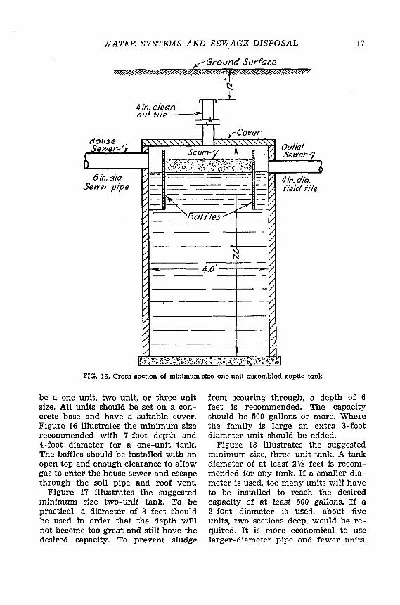
FIG. 16. Cross section of minimum-size one-unit assembled septic tank
be a one-unit, two-unit, or three-unit size. All units should be set on a concrete base and have a suitable cover. Figure 16 illustrates the minimum size recommended with 7 -foot depth and 4-foot diameter for a one-unit tank. The baffles should be installed with an open top and enough clearance to allow gas to enter the house sewer and escape through the soil pipe and roof vent.
Figure 17 illustrates the suggested minimum size two-unit tank. To be practical, a diameter of 3 feet should be used in order that the depth will not become too great and still have the desired capacity. To prevent sludge
from scouring through, a depth of 6 feet is recommended. The capacity should be 500 gallons or more. Where the family is large an extra 3-foot diameter unit should be added.
Figure 18 illustrates the suggested minimum-size, three-unit tank. A tank diameter of at least 2% feet is recommended for any tank. If a smaller diameter is used, too many units will have to be installed to reach the desired capacity of at least 500 gallons. If a 2-foot diameter is used, about five units, two sections deep, would be required. It is more economical to use larger-diameter pipe and fewer units.

18 EXTENSION BULLETIN 247
6in. Sewer pipe
4"pipe - ---- -1-- - 4 "fle/d file _ ~{3afl"les--z~ _
f)
' - <:;:)-
--- f 10 --!--- 3.0 -1------vt f-.- -1-----
~ --· ~-~-------~0 --~
----- -1--
1-------- f--
FIG. 17. Cross section of minimum-size two-unit assembled septic tank
A depth of 6 feet is essential to efficient operation of the tank. If two sections of available pipe are not 6 feet in depth it would be advisable to add an extra section, even though the depth would be greater than required.
ftouse Cover--'J Sewer1 ~
1:\. What Are the Recommended '1 Sizes and Grades for the House
Sewer and Outlet Sewer? The house sewer to the septic tank
should be a 6-inch-diameter sewer pipe laid with tightly cemented joints and
Cover/}
FIG. lB. Cross section of minimum-size three-unit assembled septic tank

WATER SYSTEMS AND SEWAGE DISPOSAL 19
with the bell end up the slope. A 6-inch diameter for both house sewer and inlet T pipe is recommended because they both carry raw sewage, and, if too small, may be plugged rather easily. A minimum of 2 per cent slope, or 1 inch in 4 feet, should be given the house sewer line, and it should be laid without bends to minimize danger of clogging. A 2-inch drop between inlet and outlet of the septic tank should be allowed, as shown in figure 13.
The outlet sewer from the septic tank to the disposal field is usually built of ordinary 4-inch drain tile. However, if it passes within 75 feet of the water supply or near willow or elm trees, it is best to use sewer pipe with tightly cemented joints. If the septic tank is working efficiently a 4-inch diameter for both outlet sewer and T pipe is sufficient because only clear liquid will flow through them. The outlet sewer should be laid on a slope of at least 1 inch in 25 feet.
(.. What Type of Disposal Field Can 1/f Be Used for Effluent after It
Has Passed Through the Septic Tank?
Final disposal of the liquid from the septic tank may be handled by discharging the effiuent into:
( 1) Tile lines laid close to the surface. (2) Dry wells. ( 3) A field tile drainage system. ( 4) A filter that drains out on the sur
face of the ground.
House
l Sepfic Tank
6in. Sewer pipe 2 %grade
(5) A filter that drains into a pit. The fluid in the pit is pumped to the top of the ground by an automatic sump pump.
Discharging Effluent Into Tile Lines Laid Close to the Surface
This type of disposal field is used on flat land where the soil is fairly heavy but still has absorptive qualities. In practically all cases the septic tank should be set close to the surface with 1 foot of cover, which means the basement cannot be drained by gravity. The basement wastes can be pumped up to the house sewer by an automatic sump pump, as indicated in figure 19. The layout of tile lines is illustrated by figure 20, A and B. The lines should be so arranged that extensions can be added. All tile lines should be approximately 75 feet from the water supply. Ordinary 4-inch field drain tile are usually laid with %-inch spacings that are covered with small strips of tarpaper to prevent fine particles of soil from clogging the line. The disposal tile lines should have a fall of 4 inches in 100 feet and should be spaced about 10 feet apart.
It is advisable to lay out the field with about 2 feet of cover over the tile lines. Soil bacteria that act on sewage to render it harmless are present in sufficient numbers only in the upper layer of soil. The top layer of a heavy soil, which is better aerated, provides much better absorption than deep layers
FIG. 19. Sump pump installation with tile disposal field layout

20 EXTENSION BULLETIN 247
@
House
Ground surface
Gravel 4 8drain h1e 4"/"a/1 pertoofl.
~ Disposal fi'e/d
er /00/1.
FIG. 20. Sewage system layout, using tile field. A. Sectional view. B. Plain view. C. Cross section of tile line.
of soil. The septic tank discharge is not being absorbed into frozen ground in winter, but, because of a temperature of approximately 50° F. in the tank, the ground under the tile lines does not freeze if a few precautions are taken. Do not lay out a field under farmstead roads. Provide a good sod cover-the front yard where grass is maintained is a good location for the disposal field. If snow does not collect naturally over the tile lines it might be advisable to provide a snow fence, such as cornstalk bundles supported by a wire stretched between steel posts. If sod and snow cover is not provided, it would be advisable to bank the lines with rotted straw bottom or hay.
Tile lines in tight soils should be cradled in gravel, cinders, or other coarse material to a depth 12 inches below the center of the tile and the width of the trench, in order to hasten final disposal of liquid (figure 20C). Remember the effluent has to seep into heavy soil through small joints between tile. By adding gravel under the tile the liquid can immediately escape from the tile into gravel and make use of about five times the ground area possible otherwise.
To supply enough area for contact between disposal liquid and the ground, it is advisable to lay out about 50 feet of tile line per person in the heavier soils.

WATER SYSTEMS AND SEWAGE DISPOSAL 21
Discharging Eftluent Into Dry Wells This type of liquid disposal is rec
ommended for use in gravel or coarse sand soils. The layout is illustrated by figure 21. A dry well is a hole in the ground with the sides walled up and the bottom left open in order that liquid may seep away into the ground strata. The side walls can be built out of blocks laid on their sides for the first 3 or 4 layers and the rest laid in the conventional manner. The openings in the blocks will allow liquid to seep into the ground for the first couple of feet if the bottom becomes plugged. The dry well may also be constructed of brick with open joints all the way up.
The cross-sectional area of the dry well should be about 25 square feetsuch as 5 feet by 5 feet or 4 feet by 6 feet. If concrete blocks are used it would be practical to lay five blocks each way with alternate layers running out to the corner to break the joints. If brick is used without mortar the dry well should be round to allow the brick to interlock.
A minimum depth of 5 feet below the inflow is suggested to build up enough hydraulic pressure to force liquid into the ground more rapidly. Precast concrete slabs 1 foot wide, as described for the septic tank, may be
House
used for the cover. The cover may be placed either 1 foot above the inflow or 1 foot below the ground surface if the side walls are extended up that far for ease in cleaning in case the dry well becomes plugged. The dry well should be at least 75 feet from the water supply.
Discharging Eftluent Into a Field Tile Drainage System
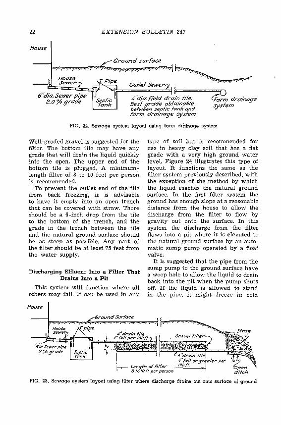
This system can be used wherever an adequate field tile drainage system can be tapped (see figure 22). If the field tile drainage system does not provide enough dilution for the effluent, it might be advisable to install a filter between the tank and the drainage system ·as shown in figure 23.
Discharging Effluent Into a Filter That Drains Out on the Surface of
the Ground This type of disposal can be used in
heavy soils where there is enough slope away from the house to install a filter and have the liquid drain out on the surface or into a ditch that is fairly well removed from the house. The layout is illustrated in figure 23. The top tile has a flat grade to allow the liquid to seep through the joints and has the lower end plugged. The filter is 2 feet deep and the width of the trench.
Ground surf'ace
House sewer
6''dia. sewer pipe 2.o%grade
Ouf!ef Sewer
4'Ciia. .field drain file 4" fall per /00 IT. ·
FIG. 21. Sewage system layout using dry well
t.o'
Dry Well
22 EXTENSION BULLETIN 247
tfouse
Ouf!el Sewer
4"dict. 1/"e/d drain file. Besl grade obfainable befween sepfic lank and t'arm drainage ~slem
~drainage syslem
FIG. 22. Sewage system layout using farm drainage system
Well-graded gravel is suggested for the filter. The bottom tile may have any grade that will drain the liquid quickly into the open. The upper end of the bottom tile is plugged. A minimum:length filter of 8 to 10 feet per person is recommended.
To prevent the outlet end of the tile from back freezing, it is advisable to have it empty into an open trench that can be covered with straw. There should be a 6-inch drop from the tile to the bottom of the trench, and the grade in the trench between the tile and the natural ground surface should be as steep as possible. Any part of the filter should be at least 75 feet from the water supply.
Discharging Effluent Info a Filfer That Drains Into a Pit
This system will function where all others may fail. It can be used in any
House
I
type of soil but is recommended for use in heavy clay soil that has a flat grade with a very high ground water level. Figure 24 illustrates this type of layout. rt functions the same as the filter system previously described, with the exception of the method by which the liquid reaches the natural ground surface. In the first filter system the ground has enough slope at a reasonable distance from the house to allow the discharge from the filter to flow by gravity out onto the surface. In this system the discharge from the filter flows into a pit where it is elevated to the natural ground surface by an automatic sump pump operated by a float valve.
It is suggested that the pipe from the sump pump to the ground surface have a weep hole to allow the liquid to drain back into 'the pit when the pump shuts off. If the liquid is allowed to stand in the pipe, it might freeze in cold
1-- Lengfh of fi/fer 8 fo 10 fl. per person
FIG. 23. Sewage system layout using filter where discharge drains out onto surface of ground

WATER SYSTEMS AND SEWAGE DISPOSAL 23
House
FIG. 24. Sewage system layout using filter where discharge drains into pit and is elevated to top of ground by automatic sump pump
weather. Surface water trouble can be held to a minimum if the filter is located on fairly high ground, or at least not in a hole.
L\_ What Maintenance Is Necessary If to Insure Good Operation of a
Septic Tank? The septic tank requires very little
attention if the disposal system is well built. A large septic tank requires much less maintenance than a small tank. All tanks should be inspected every 3 to 5 years, even though sludge removal might be required only once every 20 years. If the sludge becomes too deep in the tank it will scour out into the tile lines and tend to clog them. It is advisable to clean the tank when sludge has accumulated to a depth of 1 foot.
Tanks that have more than 1 foot of dirt over the cover should have a 4-inch tile placed in the cover at the time the cover is constructed. The tile should extend up to within 1 foot of the ground surface with a suitable cap to prevent dirt from entering. This placing of cleanout tile is indicated in figures 13 and 16.
When you are inspecting the tank, drop a measuring stick with a 2%inch-square foot through the tile opening to determine the amount of accumulated sludge. If the sludge is 1 foot
deep or over, a 2-inch pipe with a cistern pump installed on the top may be placed in the tank through the tile opening for cleaning. Cut the bottom of the pipe on an angle so that one side is about 1% inches shorter than the other. This will allow sludge to enter when the pipe is placed on the bottom of the tank. A satisfactory job of removing sludge can be accomplished by alternately pumping and flushing with clear water with a pressure hose.
A question frequently asked is: Can greasy water from the sink or soapy water from the shower, bathtub, or laundry be put into the septic tank? It has been found that a septic tank of proper size and design will handle all these wastes from the average home without trouble. A large tank will handle these wastes satisfactorily because enough liquid is present to dilute the wastes to a point where they are harmless. A septic tank is really an oversized grease trap. The grease and soap curds will either settle out in the sludge in the b,ottom or rise to the top and be collected in the scum which sometimes builds up to a thickness of one foot. If too small a tank is installed it might not handle these wastes satisfactorily.
Another question often asked is: Are washing powders injurious? It is prob-

24 EXTENSION BULLETIN 247
able that an unusual amount of acidic or alkaline waste discharged into the tank would interfere with the natural decomposition by killing the bacteria which carry on the action, but amounts of such chemicals commonly used in the home are too small to be the cause of trouble. Sometimes the discharge from a water softener, when it is being regenerated with salt, is harmful to the bacterial action in the tank. If the
water is hard and regeneration takes place often, enough salt might accumulate to kill the bacterial action. It might be advisable to attach a hose to the bottom of the water tank and drain onto the driveway through a basement window.
Never use disinfectants when cleaning the septic tank. Such materials destroy bacterial life which is the chief agent in decomposing sewage.
UNIVERSITY FARM, ST. PAUL 1, MINNESOTA Cooperative Extension Work in Agriculture and Home Economics, University of Minnesota,
Agricultural Extension Division and United States Department of Agriculture Cooperating, Paul E. Miller, Director. Published in furtherance of Agricultural Extension Acts of May 8 and June 30, 1914. 20M-5-47


