Water Source Heat
Pump (WSHP) report February 2015
Photo: http://guidetoseaton.blogspot.co.uk/p/seaton-high-rises.html

19 Feb 2015
i
The application of a large scale open water source heat pump and thermal store
within an existing combined heat and power (CHP) and district heating system
This report has been sponsored by the Local Energy Challenge Fund which has been created to
demonstrate the value and benefit of local low carbon energy economies. The new fund coincides with
the launch of the Community Energy Policy Statement which sets out the Scottish Government’s
record of support for community energy and new ambition for holistic local energy solutions.
Author: Mike Martin, February 2015
Aberdeen Heat and Power Company Ltd,
63 Cotton Street,
Aberdeen, AB11 5EG
University of Edinburgh
Institute of Governance
Chisholm House
High School Yards
Edinburgh EH1 1LZ
Contents
Abbreviations used ..................................................................................................................................... 4
Abstract ...................................................................................................................................................... 5
1. Introduction ............................................................................................................................................ 5
2. Background ............................................................................................................................................. 6
2.0 Why Consider a Heat Pump? ............................................................................................................ 6
2.1 Existing examples of use of large scale WSHPs ................................................................................ 7
2.1.1 Duindorp, Netherlands .............................................................................................................. 7
2.1.2 Drammen, Norway .................................................................................................................... 7
2.1.3 Värtan Ropsten, Stockholm ....................................................................................................... 8
2.1.4 Kingston Heights development ................................................................................................. 8
2.1.5 Plas Newydd, Anglesey .............................................................................................................. 9
2.1.6 Portsmouth Port Terminal Building ........................................................................................... 9
2.1.7 Alaska Sea Life Centre ................................................................................................................ 9
2.1.8 Nakanoshima district, Osaka ................................................................................................... 10
2.2 The large scale WSHP market sector .............................................................................................. 10
2.2.1 Friotherm AG ........................................................................................................................... 10
2.2.2 Star Refrigeration ..................................................................................................................... 10
3. Potential low grade heat sources ......................................................................................................... 10
3.1 Rivers Don and Dee ........................................................................................................................ 11
3.1.1 Flow rate .................................................................................................................................. 11
3.1.2 River Don temperatures .......................................................................................................... 12
19 Feb 2015
ii
3.1.3 A note on climate change effects ............................................................................................ 13
3.2 Sea water ........................................................................................................................................ 13
3.2.1 Sea Water conditions and temperatures ................................................................................ 14
3.2.2 The Crown Estate ..................................................................................................................... 14
3.2.3 Aberdeen Harbour ................................................................................................................... 14
3.4 Rubislaw quarry .............................................................................................................................. 14
3.5 Waste water treatment works ....................................................................................................... 14
4. Some important considerations ........................................................................................................... 15
4.1 System monitoring ......................................................................................................................... 15
4.2 Available Supply Capacity (ASC) ..................................................................................................... 15
4.5 Cooling water.................................................................................................................................. 15
4.6 Thermal storage.............................................................................................................................. 16
4.6.1 Cost of thermal store ............................................................................................................... 16
5. Heat Pump system ............................................................................................................................... 16
5.1 Case 1 – locating the WSHP at the Seaton energy centre .............................................................. 16
5.1.1 Sea water pipework construction ............................................................................................ 17
5.1.2 Water extraction from an open loop borehole ....................................................................... 18
5.1.2 Water extraction from a trench............................................................................................... 19
5.2 Case 2 – locating the WSHP at the Tillydrone energy centre ......................................................... 20
5.3 A generalised case applicable to Scottish coastal and riverine settlements.................................. 20
5.3.1 WSHP, thermal storage and grid balancing ............................................................................. 21
6. Seaton results ....................................................................................................................................... 22
6.1 operation ........................................................................................................................................ 23
6.1.1 Electricity production .............................................................................................................. 23
6.1.2 Gas consumption ..................................................................................................................... 24
6.1.3 Case A) utilisation .................................................................................................................... 24
6.1.4 Case B) utilisation .................................................................................................................... 25
6.1.5 Boiler heat output.................................................................................................................... 25
6.2 Financial model ............................................................................................................................... 26
6.2.1 The non-domestic Renewable Heat Incentive (RHI)................................................................ 26
6.2.2 Summary of how RHI works .................................................................................................... 26
6.2.4 Tariff ......................................................................................................................................... 26
6.2.5 Projected net cash inflow and the effect of RHI ...................................................................... 27
6.3 Carbon savings ................................................................................................................................ 28

19 Feb 2015
iii
6.3.1 Methodology and calculations ................................................................................................ 28
6.3.2 Carbon emissions from embodied energy .............................................................................. 28
6.3.3 Carbon savings to 2029............................................................................................................ 29
6.4 Discussion of results ....................................................................................................................... 30
7. Conclusions and proposals ................................................................................................................... 31
Acknowledgements .................................................................................................................................. 32
Appendix A – assumptions used in energyPro modelling ........................................................................ 33
A.1 External Conditions ........................................................................................................................ 33
A.2 Heat Demand ................................................................................................................................. 33
A.3 Energy Units ................................................................................................................................... 34
A.3.1 CHP units ................................................................................................................................. 34
A.3.2 Peak load boilers ..................................................................................................................... 34
A.3.3 Water source heat pump ........................................................................................................ 35
A.3.4 Thermal store .......................................................................................................................... 35
A.3.5 Operation Strategy .................................................................................................................. 35
A.3.6 Emissions ................................................................................................................................. 36
Appendix B – inputs used for projected net cash inflow ......................................................................... 36
B.1 energyPro inputs (first year) .......................................................................................................... 36
B.2 Other parameters ........................................................................................................................... 36

19 Feb 2015
4
Abbreviations used
AH&P Aberdeen Heat & Power Ltd
ASC Available Supply Capacity
ASHP Air Source Heat Pump
BODC British Oceanographic Data Centre
CHP Combined Heat and Power
CHPQA CHP Quality Assurance programme
CoP Coefficient of Performance which, in the case of a heat pump, is the
ratio of heating supplied to the electrical energy consumed.
DECC Department of Energy and Climate Change
DH District Heating
DHN District Heating Network
EA Environment Agency (covers England only)
EU EED European Union Energy Efficiency Directive
ESCo Energy Supply Company
HDPE High-density Polyethylene Pipe
MEF Marginal Emissions Factor
NT National Trust
PLC Programme Logic Controller
SCaDA Supervisory Control and Data Acquisition
SEPA Scottish Environment Protection Agency
SPF Seasonal Performance Factor
WSHP Water Source Heat Pump
19 Feb 2015
5
Abstract
This paper investigates the feasibility of using a river or sea water sourced heat pump (WSHP) system
to supply heating to the Aberdeen Heat and Power (AH&P) district heating system. Of the three
systems currently operated by AH&P, the largest Seaton was chosen due to its proximity to water
resources, namely, the sea and the river Don as well as the potential for expansion at the Seaton
energy centre. The heating demand of the Seaton system is expected to continue to increase which
will require the company to invest in new plant. The feasibility of a potential system was modelled
using energyPRO software which allows the user to carry out a comprehensive, integrated and detailed
technical and financial analysis of cogeneration systems. The quantity of heat contained within the
River Don is also determined through the examination of flow rate and water temperature data
datasets. An ammonia heat pump system is designed to extract and upgrade the heat from the river
water to a heating supply at a temperature of 80°C. The financial feasibility and carbon footprint has
also been analysed and discussed.
1. Introduction
AH&P was set up in 2002 with the specific aims of developing and operating district heating systems in
Aberdeen to deliver affordable heat for hard-to-heat properties, in particular hard-to-heat high rise
blocks, where a large proportion of residents resided in fuel poverty. The further aim was to assist
Aberdeen City Council in carbon reduction targets through delivery of low carbon heat from combined
heat and power systems. The company’s aims still remain the same today and to achieve greater
flexibility and diversity of operation the district networks also connect to nearby public and semi-public
buildings. The longer term aim is to extend the district network throughout the densely populated
public and commercial areas of Aberdeen to achieve a network of linked energy centres which could
operate on a variety of fuel sources, thus giving further diversity and efficiency of operation.
The company supports and operates energy centres at three sites, namely Stockethill, Hazlehead and
Seaton, and now supplies over 2000 flats in 26 multi-story blocks and 13 public buildings. Carbon
emissions from these buildings have reduced by 45% and typical fuel costs to tenants have been
reduced up to 50% over the previous heating system. Customer satisfaction surveys have indicated
that tenants are very satisfied with the heating system. The schemes have received four high profile
awards:
UK Housing Awards 2008 – Increasing Environmental Sustainability
UK Housing Awards 2008 – Outstanding achievement in Housing in the UK
COSLA Excellence 2008 silver award
The 2013 award for Excellence from Global District Energy Climate Awards
The Company continues to develop their district heating network and has installed a £1m extension of
underground mains towards the City Centre which provides heat to the Council’s Town House and
other public buildings én route. A fourth energy centre is under construction in Tillydrone which will
initially supply seven residential high rise blocks consisting of 450 flats, with capacity to supply heat to
the wider Tillydrone community in the future, while the original Stockethill project has recently been
doubled in size with an additional four blocks of flats connected and a new CHP engine installed in the
extended energy centre.

19 Feb 2015
6
The company relies solely on natural gas fired CHP plant and boilers to provide heat for distribution
and for electricity generation which is mainly sold to a consolidator via the National Grid. The
imperative of diversifying fuel sources and reducing carbon emissions has led AH&P to examine the
feasibility of deploying a large WSHP to supplement the heat provided by the CHP plant. By siting the
WSHP close to the CHP engine, electricity which otherwise would be exported to the grid, can be used
for the operation of the WSHP. Results from the modelling of the system with the WSHP against an
alternative case of adding an appropriately sized CHP plant to the current plant configuration indicates
that substantial carbon and cost savings can be made due to the efficiency of the WSHP and also
favourable reductions in the utilisation of peak load boilers and CHP plant.
This report presents the main findings from the modelling taking into account anticipated future heat
demand increases, availability of low grade heat from proximate water resources and availability of
different capacities of WSHP plant. It is expected that an appropriately sized heat pump could
contribute much of the base load heat demand for any of the AH&P DH schemes without incurring a
high carbon overhead or unaffordable capital and operational costs.
2. Background
2.0 Why Consider a Heat Pump?
Heat pumps – hailed as "game changing" by UK Energy Secretary Ed Davey in March 2014 and
advocated by Professor Paul Younger, Rankine Chair of Engineering at Glasgow University – were first
described by William Thomson, the first Lord Kelvin, at Glasgow University in 1852.
Modern heat pumps use electricity to turn cool water from rivers and lakes into hot water. Technology
developed in Scotland is already being used to heat 8˚C water from a fjord in Norway to 90˚C.
Water's ability to retain heat is far greater than the air, which heats up and cools down very quickly.
Any open body of water, whether a river, the sea, canal, loch or lake, can be seen as both a plentiful
and a replenishable sink of low grade heat which is ultimately derived from solar energy.
In respect to Scotland, there are numerous rivers such as the Clyde, Tay, Dee and Don as well as
9,910km of coastline giving access to exploitable and renewable low-grade water-based thermal
energy.
The water supply pipes for a WSHP system transfer lower-grade heat with the ground itself acting as
the insulator whereas district heating pipes connecting an energy centre with buildings on the heat
network have to be heavily insulated to minimise heat losses. During the summer, when the ground is
warmer, the water may even pick up energy as it flows from one point to another.
A heat pump as a form of renewable technology is eligible for the Renewable Heat Incentive (RHI). The
RHI is viewed as a key factor in meeting the Scottish Government target of 11% of heat demand from
renewables by 2020, and will play a significant role in decarbonising the heat sector by 2050.
19 Feb 2015
7
2.1 Existing examples of use of large scale WSHPs
2.1.1 Duindorp, Netherlands1
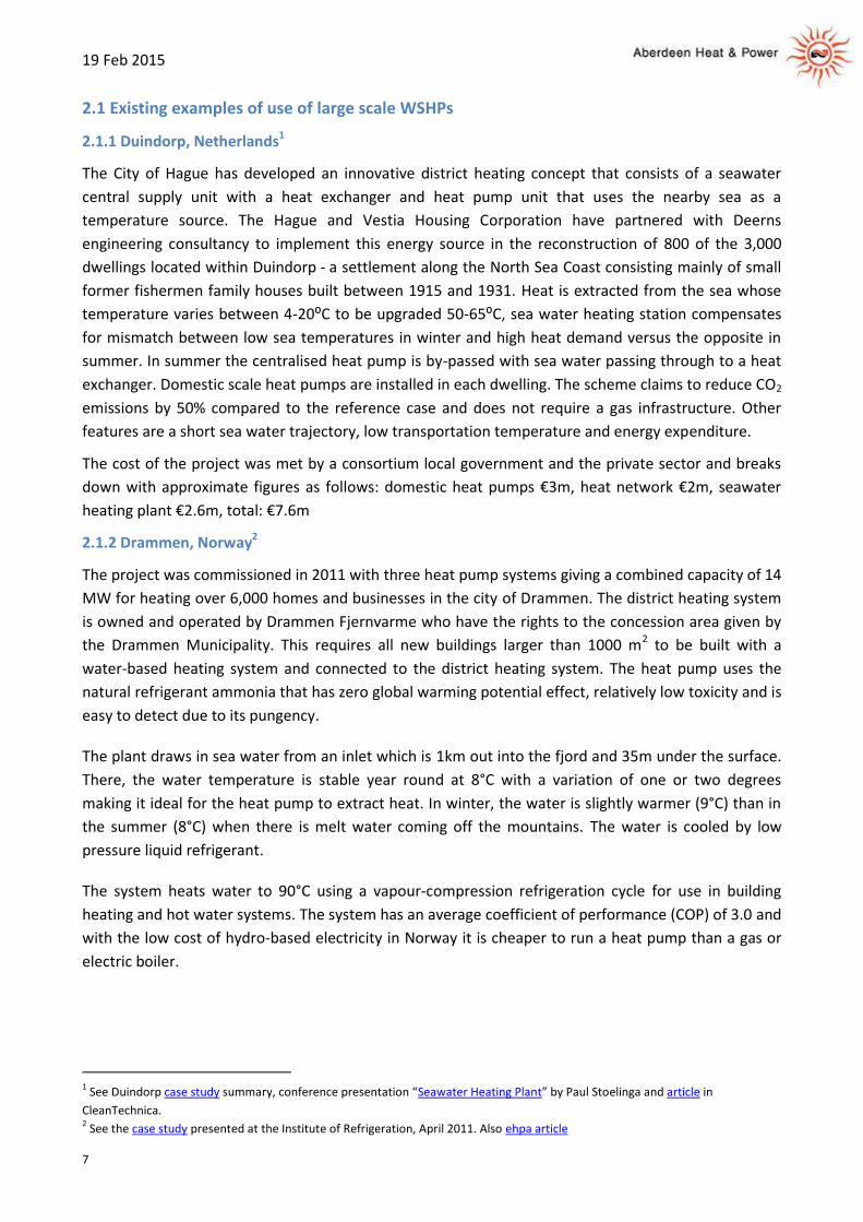
The City of Hague has developed an innovative district heating concept that consists of a seawater
central supply unit with a heat exchanger and heat pump unit that uses the nearby sea as a
temperature source. The Hague and Vestia Housing Corporation have partnered with Deerns
engineering consultancy to implement this energy source in the reconstruction of 800 of the 3,000
dwellings located within Duindorp ‐ a settlement along the North Sea Coast consisting mainly of small
former fishermen family houses built between 1915 and 1931. Heat is extracted from the sea whose
temperature varies between 4-20⁰C to be upgraded 50-65⁰C, sea water heating station compensates
for mismatch between low sea temperatures in winter and high heat demand versus the opposite in
summer. In summer the centralised heat pump is by-passed with sea water passing through to a heat
exchanger. Domestic scale heat pumps are installed in each dwelling. The scheme claims to reduce CO2
emissions by 50% compared to the reference case and does not require a gas infrastructure. Other
features are a short sea water trajectory, low transportation temperature and energy expenditure.
The cost of the project was met by a consortium local government and the private sector and breaks
down with approximate figures as follows: domestic heat pumps €3m, heat network €2m, seawater
heating plant €2.6m, total: €7.6m
2.1.2 Drammen, Norway2
The project was commissioned in 2011 with three heat pump systems giving a combined capacity of 14
MW for heating over 6,000 homes and businesses in the city of Drammen. The district heating system
is owned and operated by Drammen Fjernvarme who have the rights to the concession area given by
the Drammen Municipality. This requires all new buildings larger than 1000 m2 to be built with a
water-based heating system and connected to the district heating system. The heat pump uses the
natural refrigerant ammonia that has zero global warming potential effect, relatively low toxicity and is
easy to detect due to its pungency.
The plant draws in sea water from an inlet which is 1km out into the fjord and 35m under the surface.
There, the water temperature is stable year round at 8°C with a variation of one or two degrees
making it ideal for the heat pump to extract heat. In winter, the water is slightly warmer (9°C) than in
the summer (8°C) when there is melt water coming off the mountains. The water is cooled by low
pressure liquid refrigerant.
The system heats water to 90°C using a vapour-compression refrigeration cycle for use in building
heating and hot water systems. The system has an average coefficient of performance (COP) of 3.0 and
with the low cost of hydro-based electricity in Norway it is cheaper to run a heat pump than a gas or
electric boiler.
1 See Duindorp case study summary, conference presentation “Seawater Heating Plant” by Paul Stoelinga and article in
CleanTechnica. 2 See the case study presented at the Institute of Refrigeration, April 2011. Also ehpa article
19 Feb 2015
8
2.1.3 Värtan Ropsten, Stockholm3
With a total capacity of 180 MW, the sea water based heat pump system at Värtan Ropsten in Sweden,
is claimed to be the world’s largest. The system became fully operational in 1988 and is now operated
by the Finnish energy company Fortum.
The system consists of six Unitop® 50FY heat pump units using the R134a haloalkane refrigerant which
is hazardous and has a high global warming impact of 1,410 [4]. Each unit has a heating capacity of
30MW and uses 8MW of electricity. Output can be varied down to 10% of full capacity.
In summer warm surface water is abstracted from the sea and in winter water is taken via an inlet at a
depth of 15m where the temperature is at a constant +3°C. In winter, sea water is ingested at +2.5°C
and returned at 0.5°C
The water return and supply temperatures for the DH system are typically 57°C and 80°C.
2.1.4 Kingston Heights development5
In this West London scheme water is extracted through intakes positioned 2.5m below the surface of
the river Thames, where the temperature is relatively constant year-round. After filtering, heat is
transferred from the river water to a secondary circuit that links to a plant room where WSHPs
increase the water temperature before distribution to mini plant rooms, where the temperatures are
boosted further. The system is capable of delivering 2.3MW of heat to 137 apartments and a 142-
bedroom hotel.
When the developer was asked whether he is confident that a system of government subsidies will
reduce the pump system's £2.5 million price tag sufficiently to make the technology commercially
viable on a large scale, he responded: “It's very difficult to be precise when it comes to the cost of
installing the system - each one will be different. However, it should be possible to install the system for
the same sort of money as combustion-based technology and with the support of the government's
renewable heat incentive, it should be commercially viable.”
The developer is positive about advising other developers to do this from a technical, commercial and
environmental standpoint. He believes that the benefits that will accrue to the residents in the
development and the hotel owner will be significant in terms of reducing energy bills as well as in
terms of increased energy efficiency and reducing carbon emissions.
Water is abstracted from the river having passed through a technologically advanced stainless steel
filter that ensures that no marine life can enter the system. The abstraction filters are fitted with an
automated backwash system that is able to 'blow away' any detritus from the filter's mesh in order to
ensure that an optimum flow is maintained at all times. That water is then passed through a second,
even finer filtration process, to get rid of any silt before being fed through the heat exchangers. An
internal closed loop system then transfers the captured thermal energy to an internal plant room in
the Kingston Heights development about 200m away.
3 See: http://www.friotherm.com/webautor-data/41/vaertan_e008_uk.pdf
4 See List of refrigerants: http://en.wikipedia.org/wiki/List_of_refrigerants
5 See: http://www.cibse.org/Knowledge/Case-Studies/CIBSE-Case-Study-Kingston-Heights

19 Feb 2015
9
Having passed through the heat exchanger the river water is transferred, untreated in any way, back to
the river. It is expected to be slightly cooler by approx. 2°C with a return temperature of 7-9°C
compared with 8-10°C when extracted. According to the developer “the return water is instantly
assimilated into the main body of water and returns to ambient temperature almost immediately”. As
an element of the agreement with the Environment Agency (EA), any water returned to the river from
the closed loop system within the development will be within ±3°C of the river temperature.
2.1.5 Plas Newydd, Anglesey6
The 300kW marine source heat pump is the first commercial marine WSHP to be installed in the UK
and provides all of the heating needed by the 18th-century mansion and gardens owned by the
National Trust. The upgrade cost £600k and is expected to save around £40k a year in operating costs
by displacing the oil-fired heating system which used to consume as much as 1,500 litres of oil a day in
winter.
The award winning system takes sea water from the Menai Strait at 60m from the shoreline, through
pipes to a heat exchanger on the shore. The pipes going into the sea are protected with caissons and
blended into the shorescape using rocks. After passing through heat exchanger water (or glycol?) is
then pumped up 30m of cliff face to the mansion’s boiler house where the heat pump upgrades the
heat to 55°C. Pre-insulated pipe then carries the heated water 100m to the Country House itself where
it is used to heat the building at a temperature suitable for conservation and provide domestic hot
water.
The system became operational since May 2014 and is performing well according to the NT who have
reported a CoP of 4.08 and a SPF [7] of 2.82 as of December.
2.1.6 Portsmouth Port Terminal Building8
The Port Terminal is the sole user of a seawater heating system for use in a commercial building.
According to their website, it is the first public building in the UK to be heated and cooled using
thermal energy from seawater, dramatically reducing its carbon footprint and using only 20% of the
energy of a traditional boiler/chiller system.
2.1.7 Alaska Sea Life Centre9
The Centre which is situated at almost 60° Latitude, consider themselves to be early adopters of sea
water source heat pump technology, having chosen this technology over that of ASHP due to the
higher CoPs achievable with WSHPs. This recently constructed system (2012) is relatively small, rated
at 80-85kWe input and 288kWth output. The plant had a capital cost of $833,330 (£525k), annual
glycol pumping cost of $24,833, electricity consumption of $61,300 and O&M of $10,000. The main
objective of the project is to reduce GHG emissions and heating costs by eliminating dependency on
fuel oil.
6 See BBC article, Heat from the sea to warm historic house: and National Trust article
7 See: http://www.thegreenage.co.uk/coefficient-of-performance-seasonal-performance-factor/
8 See: http://www.portsmouth-port.co.uk/about_us/port_information#sthash.PjVv807V.dpuf
9 See: http://acep.uaf.edu/media/60861/ASLC-REAP-Forum-Presentation.pdf

19 Feb 2015
10
2.1.8 Nakanoshima district, Osaka10
As part of a drive to reduce GHG emissions WSHPs have been installed in the Nakanoshima district of
Osaka and made operational since 2004 to replace boilers and electric water heaters. Nakanoshima
has abundant water resources in the form of two rivers with water extracted from the Dojimagaw and
discharged into the Tosaborigawa. The extraction-return temperature change is kept within a range of
less than ±3℃ which is considered not to significantly impact on river life.
2.2 The large scale WSHP market sector
The large scale heat pump sector is strongly related to the well-developed refrigeration sector,
however, the application of large scale WSHPs to the DH sector has been historically limited to
Scandinavia, Switzerland and Japan. That appears to be changing under pressure from the EU Energy
Efficiency Directive (EED) and as Governments, including those of the UK and Scotland [11], seek to
diversify away from fossil fuel dependency.
So far there only appear to be two companies offering products, namely Friotherm and Star
Refrigeration.
2.2.1 Friotherm AG12
Friotherm has its roots in the Sulzer group and offers heat pumps, chillers, components and services.
The company became legally independent of its previous owners by means of a management buyout
in 2005.
Friotherm offer the Unitop® range of Heat Pumps and Chillers which span from 1MW to 10MW in
capacity and are aimed at the district cooling and district heating sectors. Each Friotherm product of is
designed and configured according to the specific needs of a client.
2.2.2 Star Refrigeration13
The Glasgow based Star Refrigeration company offer the Neatpump range of heat pumps which use
relatively benign Ammonia as a refrigerant. Neatpumps are available with capacities ranging from
350kW to 8MW with multiple modules offering a practically limitless capacity. There are several
models of water sourced heat pumps within the range.
3. Potential low grade heat sources
Recent work by the Scottish Government indicated that the total heat demand for all settlements
within 1km of the coast is 31TWh/yr and that the total (non-electrical) heat is demand 87TWh/yr for
all of Scotland although not all this demand is for low grade heat, i.e. some demand is for higher grade,
industrial heat [14].
10
Town creation by making use of “river water” summary. 11
See: Scottish Government: Towards Decarbonising Heat: Maximising the Opportunities for Scotland: Draft Heat Generation Policy
Statement for Consultation, March 2014: http://www.gov.scot/Publications/2014/03/2778 12
Friotherm AG: http://www.friotherm.com/ 13
An overview of the Neatpump range can be viewed here 14
See the presentation by Hugh Muschamp at the Stratego Coaching Session 1, 17 Nov 2014:

19 Feb 2015
11
Unused excess heat sources and resources cited by the Scottish Government include waste water
treatment works, cooling towers, abandoned mine workings, rivers, geothermal, solar and EfW plants.
In August 2014 DECC launched their river source heat map [15] which shows that there is around 40
urban rivers and estuaries in England that could provide large-scale renewable heating supplies to local
communities through water source heat pumps.
Useful work has already been done in Scotland in relation to using rivers for their low grade heat
content [16] [17].
Various heat sources have been identified in the Aberdeen City area as follows.
3.1 Rivers Don and Dee
Typically, the WSHP would take water from the river and return it at a lower temperature, by
approximately 2⁰C. The advice that AH&P has received from SEPA indicates that such an extraction
might be classifiable as a near-lossless abstraction although SEPA have said that AH&P would need to
provide a more detailed explanation of intention as part of the application process [18].
Care has to be taken in the placement of the pipes (generally coiled on mats and called pond mats) or
panels to avoid any boat traffic or debris which might float past but once submerged (usually at least a
meter deep) they would normally not require any further attention.
In Aberdeen there are two significant rivers one of which, the Don, passes close to the AH&P energy
centres at Tillydrone and Seaton and is therefore considered below. The other, the Dee, has a flow rate
[19] which is greater than although of a similar order of magnitude to that of the Don.
3.1.1 Flow rate
A dataset of the flow rate as measured close to the Parkhill Bridge (A947) at Persley was obtained from
the Centre for Ecology & Hydrology [20]. The readings have been taken daily starting from 1 Dec 1969
up until 30 Sep 2013. The rate varies from 3.553 m3/sec to 327.5m3/sec with an average of
21.14m3/sec and standard deviation of 18.92m3/sec.
It is anticipated that the main operation period for the heat pump system will be during the winter
months and therefore a flow duration curve was constructed, as depicted Figure 1 below, using flow
rate data for the period 1 Oct to 30 April each year for the years 1969 to 2012. The curve gives a more
reliable prediction for flow rate of the River Don and corresponds to that used by SEPA to help
determine the amount of water that can be extracted from the river without detrimental impact to the
environment. To illustrate with an example using the graph below, the Don flow rate is predicted to be
higher than 10m3/s for 76% of days during this period. The only limitation of this approach is that it
15
DECC’s high level water source heat map is aimed at local authorities, community groups and private developers. 16
The Conference “Harnessing Heat from Rivers” was hosted by Scottish Renewables and held on 10 Sept 2014. 17
The potential for using the river Kelvin is explored in the paper “Heating Glasgow University with River Sourced Heat Pumps”,
2014: http://www.gla.ac.uk/media/media_344366_en.pdf 18
See the SEPA abstraction regime http://www.sepa.org.uk/water/water_regulation/regimes/abstraction.aspx 19
The Dee has a flow rate of 3.664m3/sec to 571.5m
3/sec as measured by the “Dee at Park” SEPA monitoring station close to the
settlement of Drumoak in Aberdeenshire. 20
The Centre for Ecology & Hydrology, National River Flow Archive Data Holdings:
http://www.ceh.ac.uk/data/nrfa/data/data_holdings.html

19 Feb 2015
12
does not account for possible climate change effects or unusual weather events such as a prolonged
deep freeze or drought.
Figure 1 – River Don flow patterns
3.1.2 River Don temperatures
It is important to develop a good understanding of the river temperature patterns due to the risk that
the temperature falls below the threshold (typically ≤3 °C) at which the evaporator section of the heat
pump can freeze and potentially damage the system. A second risk is that the temperature falls below
4°C which would lower the Coefficient of Performance (COP) of the heat pump system to the point
that requires the system to be switched off.
River temperatures were obtained from SEPA [21] who checked their monitoring location for the
waterbody Dyce to the tidal limit and provided a summary of statistics as per table 1 below.
No. samples Avg. Min Max Std. dev. Start date End date
171 9.76 0.0 21.3 4.97 22 Feb 2000 19 Nov 2014
Table 1 – River Don temperature spread
According to SEPA, river temperatures further up the catchment are likely to be more variable and
have a wider range.
Although the SEPA figures suggest that for most of the year the temperatures would not fall below
4⁰C, given the time period over which the data was collected and the limited number of data points, a
more detailed temperature survey might need to be taken over the winter months. River temperature
data can be collected using easily affordable temperature loggers [22] placed in the river with typical
reading resolutions of 0.1°C, an accuracy of ±0.2°C and can record temperature every hour over a
period of several months. Such a degree of accuracy would be sufficient for establishing the viability of
water abstraction to supply a WSHP.
21
Scottish Environment Protection Agency: http://www.sepa.org.uk/ 22
Examples include the ThermaData® and Tinyttag model ranges.

19 Feb 2015
13
3.1.3 A note on climate change effects
Observational weather data collected since 1961 clearly shows that the climate in Scotland has
changed significantly over the last 40 years with average temperatures in Scotland increasing by 0.5°C
since 1914 and most areas have experienced a significant rise in precipitation. This is most pronounced
in winter months with the East of Scotland experiencing a 36.5% increase and the North and West of
Scotland both receiving a 67-69% increase in precipitation over 1961 levels. The only notable exception
is during the summer months in the North of Scotland which has seen a decrease in precipitation levels
with some parts of the North West being up to 45% drier [23].
3.2 Sea water
Sea water, like any water, has the ability to retain heat for a long period of time and due to the specific
heat of water it takes a lot of heat to warm it or indeed to cool it. This ability to retain heat allows
significant quantities of heat to be extracted close to urban areas with high heat demand without
detriment to the marine environment. Operational experience from the Drammen system indicated
that a 1˚C higher temperature in the sea gives a COP increase of 1.3% and performance increases of
2.8%.
For a coastal abstraction registration with SEPA is required. An extraction licence is generally required
for any extraction above 20m3/day, this generally means anything above a 4kW water source heat
pump needs an extraction license if the heat pump runs 24hrs a day. Discharge consent is also required
and it is important to consider what happens to the colder water after it has flowed through the heat
pump.
The design of seawater intake systems needs to consider a multiplicity of conditions such as scouring,
filtering and corrosion, however, long experience has been accumulated through, for example, the
operation of desalination plants [24]. Laying the pipes out to sea may require permission from the
Crown Estate and the Harbour Board.
Some of the issues and potential barriers are:
Due to the corrosive nature of seawater on the associated infrastructure requires special (and
often expensive) materials.
The sea water intake can be prone to fouling which can be from biological sources, the effects
of corrosion or sludge from ships or a combination of these factors.
Depending on distance from the shoreline, the caissons enclosing the pipes, or the pipes
themselves if caissons are not used, and sea water intake may be vulnerable to anchor drag.
Obtaining permits.
Pipes crossing or under the beach and breaching the sea wall.
23
Education Scotland: Climate change in Scotland 24
See the Design Guidelines of Seawater Intake Systems: http://www.desware.net/Sample-Chapters/D11/D05-002.pdf

19 Feb 2015
14
3.2.1 Sea Water conditions and temperatures
Sea water temperatures were obtained from BODC [25] for the BODC reference 399068 which is
1.62km from the Seaton energy centre and 1.2km from the shoreline. Temperatures were measured
on 22 Jan 1992 and range from 6.71⁰C at the surface through to 6.97⁰C at 11m depth.
3.2.2 The Crown Estate26
In Scotland the Crown Estate manages about half of the coastal foreshore and almost the entire
seabed and has a significant role in supporting ports and harbours as well as offshore renewable
energy. Their role is to make sure that the assets they invest in and manage are sustainably worked
and developed to deliver the best value over the long term. All their annual revenue profit is paid to
the UK Government.
Over the past 15 years the Crown Estate Marine Stewardship Programme has invested over £10m in
community projects and scientific research to support and enhance the UK’s marine assets. It might
behove AH&P to explore this as a possible source of funding to help cover the cost of sea pipes.
3.2.3 Aberdeen Harbour27
Aberdeen Harbour Board would need to be approached and advised of a planned pipeline
deployment, and also in respect of any future potential of sea extraction in respect of the Harbour
Board’s long term ambitions to construct a new harbour in the Nigg Bay area..
3.4 Rubislaw quarry
Rubislaw quarry is a privately owned [28], former granite quarry located at the Hill of Rubislaw in the
west end of the City. With a depth of 142m deep and a diameter of 120m, it is one of the largest man-
made holes in Europe.
The quarry is now filled with water and therefore it may be possible to abstract water and return it at
2⁰C lower temperature without adverse effects due to the large volume of water accumulated.
However, no investigation has been carried out due to the remoteness of the site from existing AH&P
heat networks.
Recent research work has been carried out by the University of Strathclyde engineering Department
on the performance of a reservoir-based water source heat pump [29].
3.5 Waste water treatment works
Kelda Water Services Grampian [30] operates waste water treatment facilities in the NE of Scotland
including at Nigg and Persley. Kelda use an anaerobic digestion process to treat sludge which produces
a valuable agricultural by-product and creates heat and power for their sites.
25
the British Oceanographic Data Centre – see: http://www.bodc.ac.uk/ 26
See: http://www.thecrownestate.co.uk/our-business/in-scotland/ 27
See: http://www.aberdeen-harbour.co.uk/ 28
The Quarry is owned by Rubislaw Quarry Aberdeen Limited – see: www.rubislawquarry.co.uk 29
Assessing the performance of a reservoir-based water source heat pump, MSc thesis by A.C.Morton, 2013. 30
See: http://www.keldawater.co.uk/our-operations/kws-grampian.aspx

19 Feb 2015
15
Although Kelda’s sites are remote from existing AH&P heat networks, it may be useful for AH&P to
determine whether Kelda returns warm water to the sea or river in the event a more proximate heat
network was being considered as part of a future expansion. There are instances of waste water
treatment plants in Norway and Japan whereby the relatively warm waste water is used as a feed to a
water source heat pump.
4. Some important considerations
4.1 System monitoring
AH&P use a building energy management system (TREND) with the principal role of monitoring
temperatures and pressures at crucial points in the three AH&P networks. TREND enables problems
such as leaks or poorly performing components to be timeously identified. In addition there are gas
and heat flow meters at various points in the system. The deployment of a WSHP would necessarily
require the installation of additional monitoring instrumentation.
4.2 Available Supply Capacity31 (ASC)
ASC or “availability” refers to the amount of electricity that the Distribution Network Operator (DNO) is
required to make available for your site. Essentially, it is the maximum electricity you can draw from
the grid at any one moment, without incurring hefty financial penalties.
ASC is measured in Kilo Volt Amperes (kVa), and for half-hourly metered sites is charged on a monthly
basis as a standing charge. Any site with a requirement of 100 kVa should be half-hourly metered.
If AH&P installs a 4MW output heat pump then there could be an additional ASC charge to cover the
supply of electricity from the grid direct to the heat pump. This requirement would be necessary to
cover periods when there was insufficient electricity generated by the CHP plant for the WSHSP.
Alternatively the system could be designed such that the WSHP would be powered down if there was
insufficient generated electricity available to run the system
Assuming the WSHP is running at full capacity then the electric demand will be 1,378.5kW which
corresponds to approximately 1,750kVa and translates to a £210 daily charge or £76,650 per annum.
4.5 Cooling water
The water returned from a WSHP will be at an approx. 2°C lower temperature than the extracted
water which makes it potentially useful for cooling purposes in buildings such as office blocks,
laboratories and, in particular, data centres. In Aberdeen there are existing datacentres, as well as
centres under construction such the brightsolid [32] Tier III Data Centre located at the Aberdeen
Journals’ Lang Stracht site.
The integration of DH and data centres is well established in Sweden and Finland where DH companies
take the surplus heat from the centres and, in what appears to be a growing trend, supply cooling
water to centres as well as other public and commercial buildings [33].
31
For more detail see: http://utilitiessavings.co.uk/resources/available-supply-capacity/ 32
See: brightsolid to open Aberdeen Data Centre, 13 Oct 2014: 33
Helsingia Energia have produced as useful summary on District Cooling: a cooling solution for climate challenges

19 Feb 2015
16
The cost of cooling is high in the UK with 1kWh of cooling costing 3p to produce [34] and therefore the
sale of cooling water could be a valuable source of income for AH&P. However, as with DH, the
delivery of cooling water would require the construction of a sub-surface network of dedicated pipes
with concomitant civils costs albeit the level of insulation need not be of the same specification as that
used by heating pipes and the cost of civils could be offset in situations where heating pipes are being
laid as part of the same project.
A recent workshop [35] jointly organised by the UK District Energy Vanguards Network and the RESCUE
[36] project addressed the opportunities and challenges of district cooling in the UK.
4.6 Thermal storage
Water based thermal stores as large as 20,000m3 have been used reliably for decades in the context of
DH networks. The use of an appropriately sized thermal store alongside a large WSHP on a heat
network enables a greater flexibility of system operation, in particular, enabling the WSHP to be run
during the night when there can be a surfeit of supply of electricity and a shortage of demand across
grid, and the potential for lower tariff charges. The WSHP can then be shut off or run at part-load
during the day to permit maximal electricity production from the CHP plant.
The benefits of including thermal storage have been demonstrated in several studies, in particular,
increased operational flexibility of the system, improved balance sheets, greater utilisation of plant
and lower GHG emissions.
4.6.1 Cost of thermal store
The cost for buying and installing a thermal store larger than 5m3 are not listed in catalogues which
reflects the requirement for larger stores to be fabricated to fit a specific site and DH system.
According to a Tyndall Centre study [37], the cost of thermal storage is approx. £1,000/m3 whereas a
recent study by UKERC [38] indicates that for tank-based thermal stores systems with a volume of
around 300m3, typical of DH systems in the UK, a cost of approx. £390/m3 should be expected.
5. Heat Pump system
5.1 Case 1 – locating the WSHP at the Seaton energy centre
34
Conversation with David Pearson of Star Refrigeration, 14 Nov 2014. 35
In July 2014 the District Energy Vanguards Network met for a workshop on Smart Cooling in Urban Europe. The workshop agenda
(with links to presentations) can be found here. 36
The project REnewable Smart Cooling for Urban Europe aims to address the key challenges for the further development of
district cooling using low and zero carbon sources: http://www.rescue-project.eu/home/ 37
The potential for thermal storage to reduce the overall carbon emissions from district heating systems, Jan 2013: Tyndall
Working Paper 157 38
UKERC study: The Future Role of Thermal Energy Storage in the UK Energy System, 25 Nov 2014.

19 Feb 2015
17
The Seaton energy centre and network is the most extensive of the three sites operated by AH&P.
Current heat demand is approximately 25GWh per annum with an annual demand growth rate of 4%
as more buildings are connected up.
The outgoing flow temperature at Seaton is typically 80°C with a return of 50°C during the cold season
and 75°C with a return of 50°C in the warmer part of the year.
The Seaton energy centre has sufficient space
to house the WSHP and it is also only 500m
from the shoreline and 850m to the centreline
of the mouth of the River Don. In both cases,
the WSHP feed pipes would need to traverse a
municipal golf course and possibly a football
pitch.
Of the two water sources, the more desirable
would appear to be sea water extraction due to
the more stable temperatures and potentially
easier access to the shoreline via an existing
opening under the Beach Promenade. In the
case of the River Don route either a busy road
would need to be closed while pipelines were
trenched or directional drilling would need to
be undertaken using specialised equipment.
5.1.1 Sea water pipework construction
A specialist subcontractor will have to be
engaged for the pipe laying.
HDPE pipes [39] of 350mm diameter with a
length of approx. 1,600m should be appropriate
and sufficient. The return pipe need not be as long as the intake pipe.
The pipes will need be laid on the seabed and anchored by fitting concrete weight rings
(anchors/blocks) and fastenings. A summary [40] of the necessary operations might be as follows:
a) Carry out a survey of the sea bed to be able to plan required operations before laying the pipes.
b) Use crane to fit concrete weight rings onto the HDPE pipes floating over the sea surface then
position the pipes.
c) Prepare offshore and onshore trenches for the pipelines. In this regard, the predetermined route
on the seabed would need to be excavated, dredged, graded, and levelled by using a floating
crane, underwater stone crusher, hydraulic polyp grab, and rock drillers. On the sea bottom, rocky
parts would need to be broken and holes filled.
39
See: https://plasticpipe.org/pdf/high_density_polyethylene_pipe_systems.pdf 40
This summary is based on a description of the construction of the seawater intake pipelines of a desalination plant in Libya by the
ARAS company.
Figure 2 - possible route for sea water pipes

19 Feb 2015
18
d) The onshore part of the HDPE pipes will be laid into the trench dug onshore by using a land crane
and excavator.
e) The offshore part of the HDPE pipes and the intake heads will be submerged into the sea and laid
into the trench at predetermined coordinates by a floating crane and tug.
f) Additional concrete weight anchors may need to be fixed onto the submerged pipes.
g) Sacrificial anodes may need to be installed on metallic parts of the equipment for cathodic
protection against corrosion.
h) During the pipe laying and in its final position, stress and tightness analyses will need to be done.
Underwater flange connections will need to be tightened by divers using a torque meter.
i) For cleaning, maintenance, and repair works of the pipeline system a pig launcher system
connecting the basin and the HDPE pipelines will possibly need to be installed, fitted and aligned
onshore.
j) Marker buoys will possibly need to be installed by using GPS at predetermined coordinates for
establishing an offshore warning system.
k) After the pipes and intake head are laid and the trench backfilled, inspection dives may be
necessary.
l) Final levelling of the pipes and intake head may need to be made by using water jets and
underwater rock drillers and the spaces under them filled by placing fabric formwork bags. Fabric
formwork bags may also be used for scour protection by placing these around the pipes and intake
heads along the route of whole pipeline.
5.1.2 Water extraction from an open loop borehole41
Consideration might also be given to the abstraction of groundwater from the sub-surface area close
to the energy centre. AH&P understand that usable quantities of water would be available as the
water-table is close to the surface in the Seaton area, although this would require to be fully
substantiated. Such an abstraction requires the sinking of one or more boreholes for extraction
together with one or more boreholes to enable the recharging of the groundwater or discharging the
cooled water to a water course such as a stream or the sea. A submergible water pump will be
installed at the bottom of the abstraction borehole.
Assuming the WSHP ran continuously for 24 hours at full output, then the maximum daily water
requirement would be 21,172m3. The extracted water temperature needs to be above 4°C and the
water might need to be filtered depending on the maximum permissible particle size for the primary
loop. The will also be maintenance and flushing considerations. AH&P would need to apply to SEPA for
an abstraction and a discharge license as there a risk of Groundwater depletion due to excessive
pumping [42].
An important aspect of borehole extraction is the use of sand packs around the lower section of the
well which filter the ground water as it flows into the slots set into the PVC casing at the bottom of the
well.
41
For a summary of borehole heat pump systems, see: http://www.eartheat.com/borehole-heat-pumps.html 42
For a description of the causes and effects of groundwater depletion, see here.

19 Feb 2015
19
Boreholes have to be specifically designed around parameters such as the amount of water to be
extracted, the sub-surface geology and the depth required. Cost escalation can occur if, for example,
the well needs to be drilled deeply or if the geology is difficult which then may require steel rather
than PVC casing for some sections of the well. However, once drilled and commissioned a well can last
for many decades.
5.1.2 Water extraction from a trench
Due to the proximity of the river Don, there is a reasonable possibility that the area around the Seaton
energy centre is underlaid by gravels from alluvial deposits saturated with seawater in which case it
would be straightforward to extract significant volumes of water via a large trench [43]. Such a trench
would be approx. 1m width by 3m in length with a depth of 5m and supported internally by concrete
rings. There would need to be approx. 100m between the trench and the discharge location. To
establish the suitability of the area for extraction a survey would need to be commissioned to establish
the depth and extent of the gravels. Typically a series of boreholes of 8 to 10 inches in diameter and
approx. 10m in depth would be drilled. SEPA might also have information from their records.
43
From a conversation with Michael Moggeridge of Land & Water Resource Consultants Ltd (LWRC)

19 Feb 2015
20
5.2 Case 2 – locating the WSHP at the Tillydrone energy centre
The Tillydrone energy centre will be completed
early this year and will initially house a natural
gas fired CHP engine with a capacity of
1,063kWe. The centre has sufficient spare floor
area and ceiling height to house a WSHP and is
relatively close (~0.3km) to the river Don. A
short distance downstream is the site of the
flume of a former paper mill where the river
flow was initially used as a power source and
subsequently as a point of water abstraction.
The route to this point is ~0.46km and is
depicted in red in Figure 4 with the shorter route
in yellow.
The scheme, which is currently under
construction, will initially supply heat to seven
blocks of flats with an estimated heat demand of
5,384MWh per annum. To justify the
deployment of a WSHP an additional heat
demand of perhaps as much again would have to
be found.
The cost of the water extraction infrastructure from a fresh water source is approx. 20% cheaper than
that for sea water extraction [32].
5.3 A generalised case applicable to Scottish coastal and riverine settlements
Coastal communities, defined as within 5km of the coast, make up 41% of the total population of
Scotland, with 68% of the coastal population living within the ‘developed coast’ which consists of
urban areas such as large towns and cities. 14% of the coastal population live within the ‘undeveloped
coast’ which consists of small towns and rural holdings as well as agricultural and forestry land [44].
There are 153 settlements in Scotland with a population in excess of 4,000 [45]. For non-coastal
settlements, the majority have practical access to a large volume water resource such as a river, canal,
loch or reservoir.
Some of these settlements will be off-mains gas [46] and some will host areas which have high heat
demand such as high density housing estates or industrial and commercial zones. It is this subset of
settlements which might be potentially suitable for a WSHP, thermal storage and heat network
combination which, with some coordination, could benefit from economies of scale and improving
supply chain performance.
44
From “Scotland’s Coastal Assets”, James Hutton Institute 45
From “Mid-2012 Population Estimates for Settlements and Localities in Scotland”, National Records of Scotland. 46
Around one third of Scottish houses are off-mains gas - mainly in small towns and rural areas - of which roughly one quarter will
be local authority/housing association properties. Scotland's Renewable Heat Strategy: Recommendations to Scottish Ministers
Figure 3 - Google Earth image of notional river pipe
routes for Tillydrone scheme

19 Feb 2015
21
Such a combination could also make use of a biomass boiler as the primary heat source which would
require a covered area for fuel storage but would not incur ASC charges.
5.3.1 WSHP, thermal storage and grid balancing
One advantage of using a WSHP over a biomass boiler is that a WSHP could be a useful consumer of
grid electricity for periods where there is generation surplus to consumption demand. The imbalance
between power generation and consumption is reflected in the ‘Settlement and Trading Charges’ of
the Balancing and Settlement Code (BSC) [47] or, alternatively, the system frequency can be used as a
measure of the state of balance of the system [48]. These imbalances can be resolved via the
temporary measure of taking generation off-line with consequential payments known as “constraint
charges” which resulted in £89.34m paid out to Scottish based generators in 2014 as per figure 4
overleaf.
Figure 4 - constraint charges for Scotland and rest of UK 2014 [49]
47
See here for a detailed explanation of the wholesale electricity market. 48
See the National Grid electricity operational information pages. 49
Taken from the National Grid monthly balancing services reports.

19 Feb 2015
22
6. Seaton results
The results described in this section are derived from successive energyPro simulations for the two
system cases labelled A) and B) as per figures 4 and 5 below.
The simulations for the two cases cover a period of 15 years with heat demand increasing by 4% per
annum.
Each simulation was run through energyPro both with and without a 200m3 thermal store.
Chart outputs for simulations without a thermal store are depicted with a broken line and are labelled
‘NS’ in the chart legend.
The two system cases are as follows:
A) Two 1,063kWe (1,300kWth) CHP plants and one 2,934kWth WSHP as per figure below.
Figure 5 - Proposed CHP, WSHP and boiler system case for Seaton

19 Feb 2015
23
B) Two 1,063kWe (1,300kWth) and one 2,679kWe (2,646kWth) CHP plants as per figure below.
Figure 6 - Alternative CHP and boiler system case for Seaton
6.1 operation
6.1.1 Electricity production
The chart below depicts electricity exported to the grid. For the WSHP case A) there are two CHP plant
producing electricity but with an increasing proportion of their total production (27% in 2015, 48% by
2029) being used to drive the WSHP and its associated water extraction pump.
Figure 7 - Electricty export MW hours per annum

19 Feb 2015
24
6.1.2 Gas consumption
Clearly, the consumption of gas is markedly lower for WSHP case A) with consequential lower gas costs
and CO2 emissions.
Figure 8 - Natural gas consumption
6.1.3 Case A) utilisation
Utilisation of the WSHP increases to meet growing heat demand with consequential but less marked
increase in CHP utilisation. The effect of a thermal store is also notable in reducing boiler usage.
Figure 9 - Plant utilisation for Case A)

19 Feb 2015
25
6.1.4 Case B) utilisation
Utilisation of the CHP plant increases to meet growing heat demand more markedly than in case A). As
with case A), the effect of a thermal store in relation to boiler usage is also notable.
Figure 10 - Plant utilisation for case B)
6.1.5 Boiler heat output
In both case A) and B), the effect of a thermal store is to reduce the dependency on peak load boilers.
Figure 11 - Boiler output for case A) and B) with and without thermal store.

19 Feb 2015
26
6.2 Financial model
6.2.1 The non-domestic Renewable Heat Incentive (RHI)
The RHI is a payment system for the generation of heat from renewable energy sources administered
by Ofgem and similar to the Feed-in Tariffs scheme for renewable electricity. It became active in the
UK on 28 Nov 2011 for non-domestic heat production.
RHI is a key measure for meeting the Scottish target of 11% of heat demand from renewables by 2020,
and is intended to play an important role in decarbonising the heat sector by 2050, with significant
progress being made by 2030.
6.2.2 Summary of how RHI works
RHI payments are made quarterly at a certain amount per kilowatt hour (kWh) of heat generated from
the WSHP. How much RHI payment received depends on:
The type of technology installed.
How much heat the WSHP can produce (its capacity).
How much heat is actually used.
WSHP RHI tariffs have two payment rates called ‘tiers’ with the tier 1 rate paid up to a certain limit
and, if more energy is used beyond this limit, the rest of the energy is paid at the tier 2 rate.
Non-domestic installations receive RHI payments based on the total measured heat output of the
WSHP and therefore heat and electrical metering will need to be installed to monitor the usage and
performance of the WSHP.
6.2.4 Tariff
For WSHPs the tariff is split in two parts, 8.7p/kWh for the first 1314 hours of operation, (a 15% load
factor) and 2.6p/kWh for any operation above 1314 hours [50]. The tariff structure is designed to stop
the generation of heat for the purpose of overclaiming the tariff.
Ofgem is responsible for publishing quarterly tariff tables showing the tariffs that will apply for each
tariff period following DECC’s quarterly tariff announcement.
DECC reviews the scheme’s expenditure forecast based on the number of accredited installations and
announces any changes to the tariffs that will apply in future. DECC advises whether any tariffs will be
reduced, the level of reduction, what the new tariffs will be, and when they will take effect. The
maximum level of reduction for any quarter, which is also known as “digression”, is set at 5%.
50
A worked example can be found in Ofgem’s website. Non-domestic RHI Guidance Volume Two: Ongoing Obligations and
Payments (Version 3.1) pages 35 and 36
19 Feb 2015
27
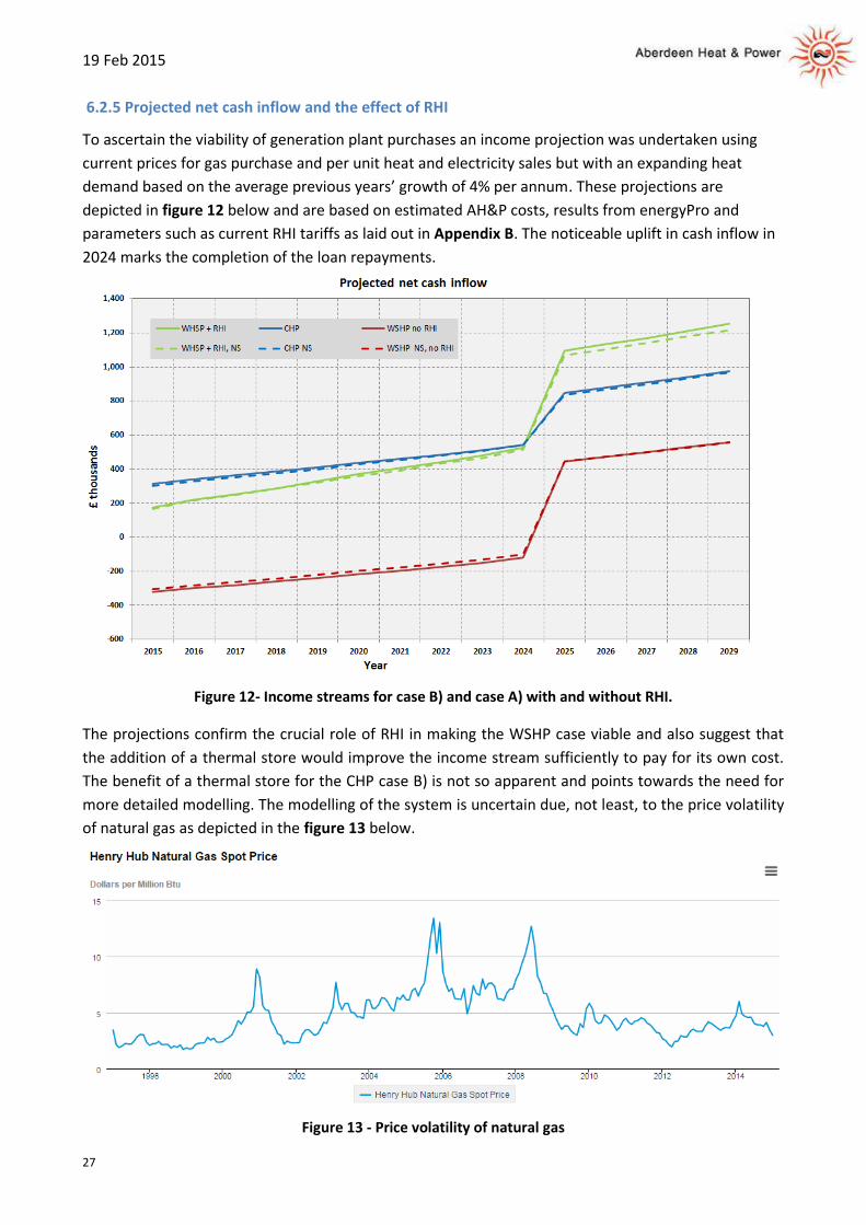
6.2.5 Projected net cash inflow and the effect of RHI
To ascertain the viability of generation plant purchases an income projection was undertaken using
current prices for gas purchase and per unit heat and electricity sales but with an expanding heat
demand based on the average previous years’ growth of 4% per annum. These projections are
depicted in figure 12 below and are based on estimated AH&P costs, results from energyPro and
parameters such as current RHI tariffs as laid out in Appendix B. The noticeable uplift in cash inflow in
2024 marks the completion of the loan repayments.
Figure 12- Income streams for case B) and case A) with and without RHI.
The projections confirm the crucial role of RHI in making the WSHP case viable and also suggest that
the addition of a thermal store would improve the income stream sufficiently to pay for its own cost.
The benefit of a thermal store for the CHP case B) is not so apparent and points towards the need for
more detailed modelling. The modelling of the system is uncertain due, not least, to the price volatility
of natural gas as depicted in the figure 13 below.
Figure 13 - Price volatility of natural gas

19 Feb 2015
28
6.3 Carbon savings
6.3.1 Methodology and calculations
Carbon savings have been calculated by taking into account key greenhouse gas releases, primarily
CO2, from the following energy consumption processes:
a) Energy consumed by the CHP plant, WSHP and boilers to produce electricity and heat (Fplant).
b) Energy saved by not running individual domestic boilers (Fsave). This figure is based on annual
heat sales of 23,000 MWh/yr.
c) Electricity not drawn down from the grid due to the operation of the CHP plant both with and
without thermal storage (Egrid).
d) Energy used in production of the WSHP, thermal store and associated installation such as
additional control instrumentation which is often referred to as “embodied energy” (Eem).
Conversion factors were applied to the above energies to give the amount of carbon saved in terms of
tonnes of CO2 per annum expressed as follows:
Csave = (Fsave*Cng/ηboil - Fplant*Cng - Eem + Egrid*CIgrid)/1000
Where:
Cng is the mass of CO2 emitted per unit of energy from burning natural gas.
Cng is derived from the calorific value of natural gas (CVng = 39.6 MJ/Nm3) converted to heat
value (HVng) and the mass of CO2 emitted per normal cubic metre (Mc=2.178 kgCO2/Nm3} as
follows:
HVng = 39.6 * 1000 /3600 = 11 kWh/Nm3
Cng = 2.178/HVng = 0.198 kgCO2/kWh
ηboil is the efficiency of domestic condensing boilers = 0.85
CIgrid is the grid carbon intensity which has a time dependent value according to the year.
6.3.2 Carbon emissions from embodied energy
The carbon emissions derived from the embodied energy of the thermal store the water source heat
pump and associated installation need also to be taken into account.
Using figures from the Tyndall Centre thermal storage paper [35], this would be 153,631 kg of CO2 for
a 200m3 thermal store which, over a nominal 25 year lifetime of the store, equates to 6.1 tonnes of
CO2 emissions per annum.
Using manufacturer’s data, the operating weight of two suitably sized WSHP units is 16,114 kg, the
embodied energy of steel is 1,770 kgCO2/tonne and therefore a very approximate guess would be
30,000 kg of CO2 without taking into account materials other than steel, instrumentation or welded
joins. To enable a figure to be included into the calculations, a multiplier of 2 has been used which
gives we get an additional 2.4 tonnes of CO2 emissions per annum over an estimated 25 year life cycle
for the WSHP. In the absence of time and data, the additional 2,679kWe CHP plant in case B) has been
taken into account with the same value.

19 Feb 2015
29
For future considerations, it would be useful to establish a more accurate value for the embodied
carbon of a range WSHPs via an approach to the manufacturers.
6.3.3 Carbon savings to 2029
The electricity produced from CHP-DH systems contributes significantly towards not only their financial
viability but also the argument for supporting CHP as a low carbon energy source through the saving of
higher carbon content electricity which otherwise would have been bought from the grid.
The CO2 emissions saved by reducing the demand for electricity supplied via the grid is typically
assessed by using an assumed grid emissions rate known as the
“marginal emissions factor” (MEF). MEFs are higher than system
average emission factors because the power stations that will
be typically switched off in the short term (or not built in the
long term) in response to a reduction in electricity demand are
likely to be marginal plant such as non-CHP gas fired power
stations rather than coal, hydro, wind or nuclear.
For those CHP-DH systems which are fuelled by natural gas as
opposed to Energy from Waste (EfW) or biomass, an accurate
estimation as to which MEFs to use is crucial in determining the
degree to which these systems have a comparative advantage in
terms of emissions savings over competing forms of energy
generation. However, the recent Government methodology
paper for emission factors [51] states that “From 2013 emission
factors per unit of electricity consumed will no longer be
provided, since these were being previously misused.”
Therefore, for the purpose of this study, two sets of grid
emission factors have been used with the first set erring
towards low (i.e. optimistic) MEFs and the second set derived
from the first but 25% higher as per table 2.
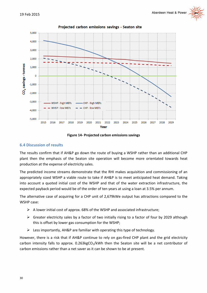
Figure 14 overleaf depicts the projected emissions performance of the Seaton system for case A) and
B) based on the MEFs in table 2. Clearly and predictably, case A) using the WSHP is the more
sustainable due to the heat pump lowering the consumption of natural gas compared with case B)
with the 2,679kWe CHP plant.
It should be noted that case B) becomes a net carbon contributor by 2022 where low MEFs are applied and
2025 for high MEFs.
51
2013 Government GHG Conversion Factors for Company Reporting: Methodology Paper for Emission Factors
Table 2 - marginal emissions factors
19 Feb 2015
30
Figure 14- Projected carbon emissions savings
6.4 Discussion of results
The results confirm that if AH&P go down the route of buying a WSHP rather than an additional CHP
plant then the emphasis of the Seaton site operation will become more orientated towards heat
production at the expense of electricity sales.
The predicted income streams demonstrate that the RHI makes acquisition and commissioning of an
appropriately sized WSHP a viable route to take if AH&P is to meet anticipated heat demand. Taking
into account a quoted initial cost of the WSHP and that of the water extraction infrastructure, the
expected payback period would be of the order of ten years at using a loan at 3.5% per annum.
The alternative case of acquiring for a CHP unit of 2,679kWe output has attractions compared to the
WSHP case:
A lower initial cost of approx. 68% of the WSHP and associated infrastructure;
Greater electricity sales by a factor of two initially rising to a factor of four by 2029 although
this is offset by lower gas consumption for the WSHP;
Less importantly, AH&P are familiar with operating this type of technology.
However, there is a risk that if AH&P continue to rely on gas-fired CHP plant and the grid electricity
carbon intensity falls to approx. 0.263kgCO2/kWh then the Seaton site will be a net contributor of
carbon emissions rather than a net saver as it can be shown to be at present.
19 Feb 2015
31
7. Conclusions and proposals
In the course of this year, AH&P will need to make a decision as to how to expand the capacity of the
Seaton system to meet growing heat demand. The modelling of the Seaton system demonstrates that
both the upgrade options under consideration, namely a WSHP and an additional CHP plant are viable.
The following points may help to inform the deliberation:
Cost:
The capital cost for the size of WSHP under consideration is approx. £4m depending on the
type of water source abstraction and associated construction costs e.g. sea, river or ground
water. By contrast, the additional CHP plant considered in this study would cost approx. £2.1m.
The RHI makes the purchase of a WSHP a practical proposition; moreover, since AH&P can
divert electricity from existing CHP plant to power the WSHP without incurring ASC charges,
the potential viability of the WSHP is further enhanced. See section 6.2.5
In both the WSHP and CHP case an application for a low interest loan to the District Heating
Loan Fund [52] and/or other funding sources will need to be considered.
Business model:
If AH&P wished to avoid the capital cost and risk of purchasing a WSHP then consideration
might be given to an installation and maintenance agreement with the WSHP provider
whereby the provider installs and operates the WSHP plant and sells heat to AH&P at an
agreed price and period of time e.g. 10 years, after which AH&P is given the option of buying
the plant at a depreciated cost. This model is often referred to as an “ESCO within an ESCO”
Carbon footprint:
In relation to carbon emissions, the modelling shows that the WSHP has a significant advantage
over an additional CHP plant assuming that grid decarbonisation continues at the current rate
and that CHP plant at AH&P continues to use fossil fuel derived gas. See section 6.3.3
Familiarity with technology:
Personnel at AH&P are already highly experienced in relation to CHP plant. If AH&P goes down
the WSHP route then staff would be a need to be trained as WSHPs are based on quite
different (refrigeration) technology.
Resilience:
The inclusion of a WSHP in the generation portfolio of AH&P would increase the diversity of
heat supply and therefore enhance the resilience of the system provided a reliable source of
electricity can be guaranteed.
52 The District Heating Loan Fund offers loans to support the development of district heating networks in Scotland.
Further information on accessing the scheme is available from the Energy Saving Trust.

19 Feb 2015
32
Risk:
While the technology of installation a WSHP may be understood or gained, there is a perceived
risk on development of such a project in respect of licensing and technicalities of extraction
from the sea. The work flow itemised under section 5.1.1 would need to be carefully
researched in respect of potential capital cost implications and effects on the environment
and marine life, along with the timescale required to plan and implement such measures.
If AH&P wish to consider the acquisition of a WSHP then a detailed study of the optimum method of
extracting local (salt) water sources would need to be commissioned with a specialist company. If the
result of this points towards abstraction from the sea, then an approach to the Crown Estate Marine
Stewardship Programme or other source with a funding proposal to help cover the cost of sea pipes
could be considered.
In the longer term there are other, more general avenues of research which might be usefully pursued
perhaps as a joint venture with one or both of the Aberdeen based Universities and the City Council as
follows:
The compilation of a detailed map consisting of local heating and cooling demand which might
be satisfied in the future by heating and cooling networks as part of a strategic energy plan for
Aberdeen. Examples such as the possible utilisation of low grade heat from a waste water
treatment plant or the need to satisfy cooling demand from server centres would be relevant.
It is envisaged that this project would work in with the Scottish Heat Map project [53].
An investigation into electricity and heating provision for ships berthing at Aberdeen Harbour
as is being done in Gothenburg [54]. This is especially important due to the consistently poor
air quality in some parts of Aberdeen and is already the subject of consideration by the City
Council.
Further research might usefully be carried out to evaluate the feasibility of using WSHPs and
thermal storage for grid balancing as outlined in section 5.3.1
Acknowledgements
The author wishes to thank Mr Ian Booth, the manager at AH&P for his support and guidance during
this project. The author would also like to thank Bill Rowe of Integrated Energy Utilities, Tina
Buchannan of Teno Accounting, Michael King of District Energy Development, Mr Dave Pearson of Star
Refrigeration and also Dr David Toke of Aberdeen University who helped to catalyse the WSHP idea.
53
See Scotland’s Heat Map 54
See Stena Line reduces emissions with district heating
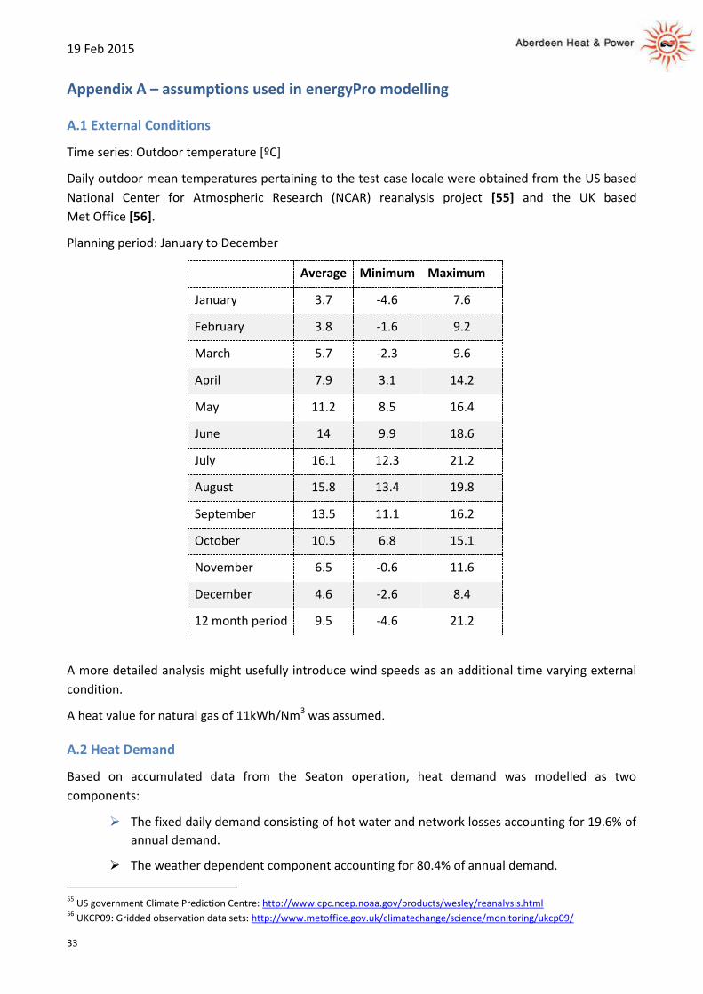
19 Feb 2015
33
Appendix A – assumptions used in energyPro modelling
A.1 External Conditions
Time series: Outdoor temperature [ºC]
Daily outdoor mean temperatures pertaining to the test case locale were obtained from the US based
National Center for Atmospheric Research (NCAR) reanalysis project [55] and the UK based
Met Office [56].
Planning period: January to December
Average Minimum Maximum
January 3.7 -4.6 7.6
February 3.8 -1.6 9.2
March 5.7 -2.3 9.6
April 7.9 3.1 14.2
May 11.2 8.5 16.4
June 14 9.9 18.6
July 16.1 12.3 21.2
August 15.8 13.4 19.8
September 13.5 11.1 16.2
October 10.5 6.8 15.1
November 6.5 -0.6 11.6
December 4.6 -2.6 8.4
12 month period 9.5 -4.6 21.2
A more detailed analysis might usefully introduce wind speeds as an additional time varying external
condition.
A heat value for natural gas of 11kWh/Nm3 was assumed.
A.2 Heat Demand
Based on accumulated data from the Seaton operation, heat demand was modelled as two
components:
The fixed daily demand consisting of hot water and network losses accounting for 19.6% of
annual demand.
The weather dependent component accounting for 80.4% of annual demand.
55
US government Climate Prediction Centre: http://www.cpc.ncep.noaa.gov/products/wesley/reanalysis.html 56
UKCP09: Gridded observation data sets: http://www.metoffice.gov.uk/climatechange/science/monitoring/ukcp09/
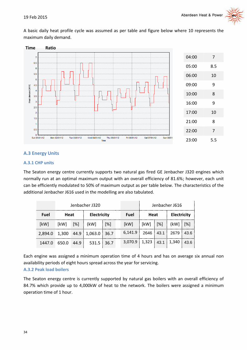
19 Feb 2015
34
A basic daily heat profile cycle was assumed as per table and figure below where 10 represents the
maximum daily demand.
Time Ratio
04:00 7
05:00 8.5
06:00 10
09:00 9
10:00 8
16:00 9
17:00 10
21:00 8
22:00 7
23:00 5.5
A.3 Energy Units
A.3.1 CHP units
The Seaton energy centre currently supports two natural gas fired GE Jenbacher J320 engines which
normally run at an optimal maximum output with an overall efficiency of 81.6%; however, each unit
can be efficiently modulated to 50% of maximum output as per table below. The characteristics of the
additional Jenbacher J616 used in the modelling are also tabulated.
Jenbacher J320 Jenbacher J616
Fuel Heat Electricity Fuel Heat Electricity
[kW] [kW] [%] (kW] [%] [kW] [kW] [%] (kW] [%]
2,894.0 1,300 44.9 1,063.0 36.7 6,141.9 2646 43.1 2679 43.6
1447.0 650.0 44.9 531.5 36.7 3,070.9 1,323 43.1 1,340 43.6
Each engine was assigned a minimum operation time of 4 hours and has on average six annual non
availability periods of eight hours spread across the year for servicing.
A.3.2 Peak load boilers
The Seaton energy centre is currently supported by natural gas boilers with an overall efficiency of
84.7% which provide up to 4,000kW of heat to the network. The boilers were assigned a minimum
operation time of 1 hour.

19 Feb 2015
35
A.3.3 Water source heat pump
The WSHP has a minimum operation time of 1 hour and coefficient of performance dependent on
output as per the table below.
Heat Electricity
Consumption
CoP Pump
[kW] [kW] [kW]
2,934.1 927.5 3.16 72.5
1,457.2 484.2 3.11 36.0
740.7 298.8 2.48 18.3
An additional electrical load has been added due to the pumping required for the river or sea water
extraction.
A.3.4 Thermal store
A thermal store with a net volume of 200m3 and utilization of 90% was optionally specified. The
temperature at the top of the store was set to 80°C and to 50°C at the bottom giving a difference of
30°C and a capacity of 6.3MWh.
Storage thermal loss was not modelled due to time constraints.
The store volume was chosen to cover one hours of heat demand at maximum load during the cold
period.
A.3.5 Operation Strategy
The operational strategy gives the WSHP priority during the night as per table:
Priority of
productions Day Night
Production to
store allowed
Partial load
allowed
Gas engine 1 1 1 Yes Yes
Gas engine 2 2 3 Yes Yes
Boilers 10 10 No Yes
WSHP 3 2 Yes Yes
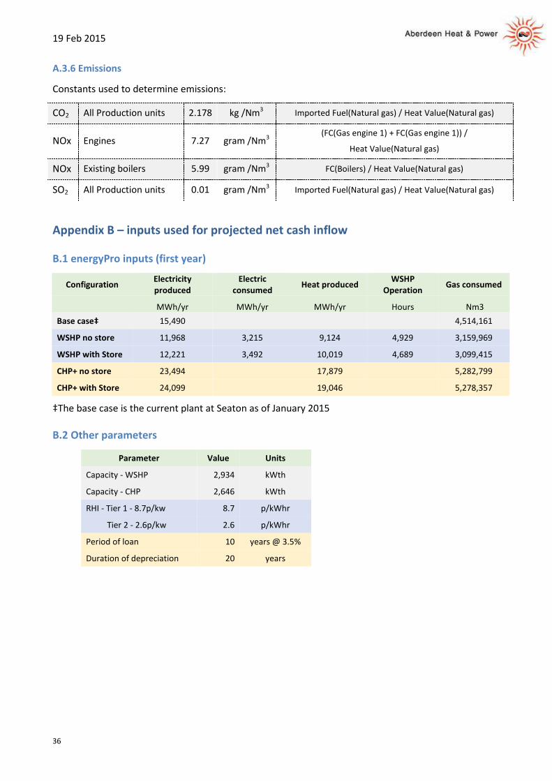
19 Feb 2015
36
A.3.6 Emissions
Constants used to determine emissions:
CO2 All Production units 2.178 kg /Nm3 Imported Fuel(Natural gas) / Heat Value(Natural gas)
NOx Engines 7.27 gram /Nm3 (FC(Gas engine 1) + FC(Gas engine 1)) /
Heat Value(Natural gas)
NOx Existing boilers 5.99 gram /Nm3 FC(Boilers) / Heat Value(Natural gas)
SO2 All Production units 0.01 gram /Nm3 Imported Fuel(Natural gas) / Heat Value(Natural gas)
Appendix B – inputs used for projected net cash inflow
B.1 energyPro inputs (first year)
Configuration Electricity produced
Electric consumed
Heat produced WSHP
Operation Gas consumed
MWh/yr MWh/yr MWh/yr Hours Nm3
Base case‡ 15,490
4,514,161
WSHP no store 11,968 3,215 9,124 4,929 3,159,969
WSHP with Store 12,221 3,492 10,019 4,689 3,099,415
CHP+ no store 23,494
17,879
5,282,799
CHP+ with Store 24,099
19,046
5,278,357
‡The base case is the current plant at Seaton as of January 2015
B.2 Other parameters
Parameter Value Units
Capacity - WSHP 2,934 kWth
Capacity - CHP 2,646 kWth
RHI - Tier 1 - 8.7p/kw 8.7 p/kWhr
Tier 2 - 2.6p/kw 2.6 p/kWhr
Period of loan 10 years @ 3.5%
Duration of depreciation 20 years


