W a t e r R e f r i g e r a t o r s
MAINTENANCE AND OPERATING MANUAL
38178800023
MCCG - CG 013÷301

W a t e r R e f r i g e r a t o r s

MCCG - CG 013÷301
3MAINTENANCE AND OPERATING MANUAL
Electronic control quick reference guide
CHAPTER 1
ELECTRONIC CONTROL QUICK REFERENCE GUIDEThe machines are equipped with an electronic control panel, which can be programmed by means of some buttons. It controls the operation
of refrigerant circuits basing on the measured control parameters. Here below are indicated some basic instructions to start the unit. For
further information consult Electronic Board chapter.
1 . 1 U n i t s w i t c h i n g o n a n d o f f
ATTENTIONBefore switching on the unit be sure that all personnel have read and understood the Chapter 3 “Safety” of this manual.
Press the button for 5 seconds to start up the machine.
The led of icon flashes for 5 seconds then it remains lit.
1 . 2 H o w t o p u t t h e u n i t i n s t a n d b yStand-by modality is obtained every time the unit is switched off.
It is indicated by the symbol lit.
Also in stand-by modality the controller can:
1. Display the measured values
2. Manage the alarms by displaying and signalling.
1 . 3 D i s p l a y
The display is divided in 3 zones (for further information please consult Chapter 8 “User interface”).
Upper-left zone: it displays the evaporator’s temperature.
Lower-left zone: It displays the condensation temperature / pressure or the hour.
Right zone: Signalling icons.
1 . 4 I n f o r m a t i o n a b o u t t h e s t a t u s o f t h e u n i t1.4.1 Display icons
ICON MEANING ICON MEANING
Celsius degrees (If displayed) Low pressure alarm
Fahrenheit degrees (If not displayed) Antifreeze resistance
Bar/Psi Pump ON
Compressor 1 Flow meter alarm
Compressor 2 Time to defrost starting (hour)
Stand-by unit Fan ON
General alarm Indication for Function Menu entering
High pressure alarm
MCCG - CG 013÷301
4 MAINTENANCE AND OPERATING MANUAL
Electronic control quick reference guide
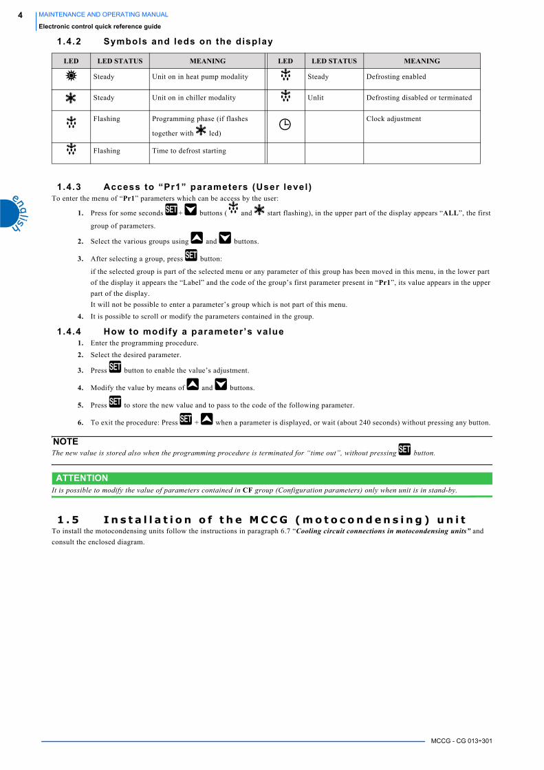
1.4.2 Symbols and leds on the display
1.4.3 Access to “Pr1” parameters (User level)To enter the menu of “Pr1” parameters which can be access by the user:
1. Press for some seconds + buttons ( and start flashing), in the upper part of the display appears “ALL”, the first
group of parameters.
2. Select the various groups using and buttons.
3. After selecting a group, press button:
if the selected group is part of the selected menu or any parameter of this group has been moved in this menu, in the lower part
of the display it appears the “Label” and the code of the group’s first parameter present in “Pr1”, its value appears in the upper
part of the display.
It will not be possible to enter a parameter’s group which is not part of this menu.
4. It is possible to scroll or modify the parameters contained in the group.
1.4.4 How to modify a parameter’s value1. Enter the programming procedure.
2. Select the desired parameter.
3. Press button to enable the value’s adjustment.
4. Modify the value by means of and buttons.
5. Press to store the new value and to pass to the code of the following parameter.
6. To exit the procedure: Press + when a parameter is displayed, or wait (about 240 seconds) without pressing any button.
NOTEThe new value is stored also when the programming procedure is terminated for “time out”, without pressing button.
ATTENTIONIt is possible to modify the value of parameters contained in CF group (Configuration parameters) only when unit is in stand-by.
1 . 5 I n s t a l l a t i o n o f t h e M C C G ( m o t o c o n d e n s i n g ) u n i tTo install the motocondensing units follow the instructions in paragraph 6.7 “Cooling circuit connections in motocondensing units” and
consult the enclosed diagram.
LED LED STATUS MEANING LED LED STATUS MEANING
Steady Unit on in heat pump modality Steady Defrosting enabled
Steady Unit on in chiller modality Unlit Defrosting disabled or terminated
Flashing Programming phase (if flashes
together with led)
Clock adjustment
Flashing Time to defrost starting
MCCG - CG 013÷301
5MAINTENANCE AND OPERATING MANUAL
Index
INDEXChapter 1
ELECTRONIC CONTROL QUICK REFERENCE GUIDE ..................................................................................31.1 Unit switching on and off................................................................................. 31.2 How to put the unit in stand by ........................................................................ 31.3 Display ............................................................................................................ 31.4 Information about the status of the unit ........................................................... 3
1.4.1 Display icons ........................................................................................ 31.4.2 Symbols and leds on the display .......................................................... 41.4.3 Access to “Pr1” parameters (User level) ............................................ 41.4.4 How to modify a parameter’s value ..................................................... 4
1.5 Installation of the MCCG (motocondensing) unit ........................................... 4INDEX ...........................................................................................................................................................5
Chapter 2
GENERAL INFORMATION ............................................................................................................................92.1 Description ....................................................................................................... 92.2 How to interpret the code of the model.......................................................... 10
Chapter 3
SAFETY.......................................................................................................................................................113.1 General ........................................................................................................... 113.2 General precautions........................................................................................ 11
3.2.1 Liquids of the user circuit .................................................................. 113.2.2 Lifting and carriage precautions ....................................................... 113.2.3 Installation precautions ..................................................................... 143.2.4 Precautions during operation ............................................................ 143.2.5 Maintenance and repair precautions ................................................. 14
3.3 Refrigerant gases ............................................................................................ 143.3.1 Refrigerant safety schedule ................................................................ 15
Chapter 4
TECHNICAL DATA......................................................................................................................................174.1 Main technical data ........................................................................................ 174.2 Other data relative to the standard machines MCCG-CG.............................. 174.3 Performance ................................................................................................... 18
Chapter 5
DESCRIPTION .............................................................................................................................................215.1 General ........................................................................................................... 215.2 Operating principle......................................................................................... 215.3 Materials......................................................................................................... 21
5.3.1 Casing ................................................................................................ 215.3.2 Materials in contact with the liquid of the user circuit ...................... 21
5.4 Components.................................................................................................... 215.4.1 Compressors ...................................................................................... 215.4.2 Condenser .......................................................................................... 225.4.3 Evaporator (only CG models) ............................................................ 225.4.4 Fan/s .................................................................................................. 225.4.5 Hydraulic group (only CG models) ................................................... 235.4.6 Antifreeze resistance .......................................................................... 23
5.5 Overall dimension .......................................................................................... 235.6 Minimum distances from walls in the installation ambient ........................... 235.7 Water and refrigerant circuits......................................................................... 23
5.7.1 Water circuit (only CG models) ......................................................... 235.7.2 Refrigerant circuit (only CG models) ................................................ 235.7.3 Refrigerant circuit for motocondensing version ................................ 23
5.8 Electrical circuit ............................................................................................. 24

MCCG - CG 013÷301
6 MAINTENANCE AND OPERATING MANUAL
Index
Chapter 6
INSTALLATION .......................................................................................................................................... 256.1 Inspection....................................................................................................... 256.2 Positioning ..................................................................................................... 256.3 Antifreeze protection ..................................................................................... 256.4 Hydraulic circuit (only CG units) .................................................................. 256.5 Expansion tank............................................................................................... 266.6 Electrical connections .................................................................................... 276.7 Cooling circuit connections in motocondensing units ................................... 28
Chapter 7
START UP................................................................................................................................................... 31
Chapter 8
ELECTRONIC BOARD ................................................................................................................................ 338.1 User interface ................................................................................................. 33
8.1.1 Display ............................................................................................... 338.1.2 Display icons ..................................................................................... 33
8.2 Function of buttons ........................................................................................ 348.2.1 Function of combined buttons .......................................................... 34
8.3 Symbols and leds on the display.................................................................... 348.4 Remote terminal............................................................................................. 34
8.4.1 Function of buttons ............................................................................ 348.5 Displaying during an alarm ........................................................................... 35
8.5.1 Alarm icons ........................................................................................ 358.6 How to silence the buzzer .............................................................................. 358.7 First start up ................................................................................................... 358.8 How to regulate the clock (NOT ENABLE IN THESE UNITS) .................. 358.9 Programming by “Hot Key” .......................................................................... 35
8.9.1 How to programme the unit by a programmed key (Download) ....... 358.9.2 How to store the parameters of the unit in the key “UPL” ............... 36
8.10 Programming by keyboard............................................................................. 368.10.1 Access to “Pr1” parameters (User level) ......................................... 368.10.2 How to modify a parameter’s value .................................................. 36
8.11 Values displayed (parameter CF36) .............................................................. 378.12 Unit switching on / off ................................................................................... 378.13 How to put the unit in stand by...................................................................... 378.14 Function menu ( button)........................................................................... 37
8.14.1 Access to Function menu ................................................................... 378.14.2 Exit Function menu ............................................................................ 378.14.3 How to display the alarms “ALrM” .................................................. 378.14.4 How to reset an alarm “rSt” ..................................................................... 378.14.5 Displaying the operating hours of loads “C1Hr - C2Hr - PFHr” .... 38
8.15 Other functions by keyboard.......................................................................... 388.15.1 How to display the Set Point ............................................................. 388.15.2 How to modify the Set Point .............................................................. 38
8.16 Alarm codes and actions ................................................................................ 398.17 Outlet blocking .............................................................................................. 428.18 Parameters description................................................................................... 43
8.18.1 Thermoregulation parameters ........................................................... 438.18.2 Configuration parameters ................................................................. 438.18.3 Dynamic set point parameters (NOT ENABLED FUNCTION) ........ 458.18.4 Energy Saving parameters (NOT ENABLED FUNCTION) .............. 458.18.5 Compressor parameters .................................................................... 458.18.6 Ventilation parameters ...................................................................... 458.18.7 Antifreeze support boiler resistance parameters ............................... 458.18.8 Defrosting parameters ....................................................................... 458.18.9 Alarm parameters .............................................................................. 468.18.10LASER operating parameters (NOT ENABLED FUNCTION) ........ 46
MCCG - CG 013÷301
7MAINTENANCE AND OPERATING MANUAL
Index
8.19 Parameter setting ............................................................................................ 468.19.1 Thermoregulation parameters ........................................................... 468.19.2 Configuration parameters .................................................................. 468.19.3 Dynamic Set-Point Parameters (NOT ENABLED FUNCTION) ....... 478.19.4 Energy Saving Parameters (NOT ENABLED FUNCTION) .............. 478.19.5 Compressor parameters ..................................................................... 478.19.6 Fan parameters .................................................................................. 478.19.7 Antifreeze resistance/supply parameters ........................................... 478.19.8 Defrosting parameters ....................................................................... 488.19.9 Alarm parameters .............................................................................. 488.19.10LASER parameters (NOT ENABLED FUNCTION) ......................... 48
8.20 Probe description............................................................................................ 48
Chapter 9
OTHER COMPONENTS SETTING ................................................................................................................499.1 Refrigerant high and low pressure switches................................................... 499.2 Speed regulator and fan pressure switch ........................................................ 509.3 Water differential pressure switch (ONLY CG UNITS) ............................... 50
Chapter 10
OPERATION AND MAINTENANCE ..............................................................................................................5110.1 Operation........................................................................................................ 5110.2 Maintenance ................................................................................................... 51
10.2.1 Unit access ......................................................................................... 5110.2.2 Water circuit emptying ....................................................................... 53
10.3 Maintenance schedule .................................................................................... 54
Chapter 11
TROUBLE SHOOTING .................................................................................................................................55
AnnexedCID xxx Overall dimension
CIF xxx refrigerant drawings

MCCG - CG 013÷301
8 MAINTENANCE AND OPERATING MANUAL
Index

MCCG - CG 013÷301
9MAINTENANCE AND OPERATING MANUAL
General Information
CHAPTER 2
GENERAL INFORMATION2 . 1 D e s c r i p t i o n
The machines described in this manual are called “WATER REFRIGERATORS” or simply “REFRIGERATORS”.
This manual is written for those responsible for the installation, use and maintenance of the unit.
These refrigerators have been designed exclusively for civil applications to cool a liquid flow.
The components used are of high quality and all the projecting process, from the production to the unit checking, has been manufactured in
conformity with ISO 9001 norms.
In most applications, the liquid of the user circuit is water and the term “WATER” will be used even if the liquid of the user circuit is
different from water (e.g. a mixture of water and glycol).
Here below the term “PRESSURE” will be used to indicate the gauge pressure.
The following symbols are shown on the stickers on the unit as well as on the overall dimension drawing and refrigeration circuits in this
manual.
Their meaning is the following:
Water inlet in the machineInstall an adequate water filter on the inlet pipelines
Water outlet from the machine
Indications for lifting the unit
Water drainage point from the machine
Water filling point
Cooling air flow
Direction of the refrigerant gas flow and water circuit
Direction of pump rotation (if installed) and of fan rotation
Electric shock risk
Air vent

MCCG - CG 013÷301
10 MAINTENANCE AND OPERATING MANUAL
General Information
To describe the unit components it is necessary the MODEL and the CODE NUMBER.
2 . 2 H o w t o i n t e r p r e t t h e c o d e o f t h e m o d e l
* Inlet water temperature 12°C, outlet water temperature 7°C, ambient temperature 35°C.
In CG - MCCG 013÷301 model
ATTENTIONThis manual provides the user, installer and maintenance technician with all the technical information required for installation, operation and carrying out routine maintenance operations to ensure long life.If spare parts are required, this must be original.Requests for SPARE PARTS and for any INFORMATION concerning the unit must be sent to the distributor or to the nearest service centre, providing the MODEL and MACHINE NUMBER shown on the machine data plate and on the first page of this manual.
MODELLOMCCG-CG013÷020
DESCRIPTION
Cooling capacity expressed in HP at nominal conditions *
Cygnus model code
MCCygnus model code. MC is written only in the motocondensing units
Table 1 HOW TO INTERPRET THE CODE OF THE MODEL
MCCG-CG031÷301MODEL
DESCRIPTION
N° of cooling circuits
Cooling capacity expressed in HP at nominal conditions *
Cygnus model code
MCCygnus model code. MC is written only in the motocondensing units
MC C G � � �
MC C G � � �

MCCG - CG 013÷301
11MAINTENANCE AND OPERATING MANUAL
Safety
CHAPTER 3
SAFETYThis machinery was designed to be safe in the use for which it was planned provided that it is installed, started up and maintained in
accordance with the instructions contained in this manual.
The manual must therefore be studied by all those who want to install, use or maintain the unit.
The machine contains electrical components which operate at the line voltage, and also moving parts as fans and/or pump.
It must therefore be isolated from the electricity supply network before being opened.
All maintenance operations which require access to the machinery must be carried out by expert or appropriately trained persons who have a
perfect knowledge of the necessary precautions.
Avoid the presence of children in the unit installation place.
3 . 1 G e n e r a lWhen handling or maintaining the unit and all auxiliary equipment, the personnel must operate with care observing all instructions
concerning health and safety at installation site.
Most accidents which occur during the operation and maintenance of the machinery are a result of failure to observe basic safety rules or
precautions.
An accident can often be avoided by recognising a situation that is potentially hazardous.
The user should make sure that all personnel concerned with operation and maintenance of the unit and all auxiliary equipment have read and understood all warnings, cautions, prohibitions and notes written in this manual as well as on the unit.
Improper operation or maintenance of the unit and auxiliary equipment could be dangerous and result in an accident causing injury or death.
Do not operate the unit and auxiliary equipment until the instructions in the Operating section of this manual are understood by all personnel
concerned.
Do not carry out any servicing, repair or maintenance work on the unit and auxiliary equipment until the instructions in the relevant sections
of this manual are clearly understood by all personnel concerned.
We cannot anticipate every possible circumstance which might represent a potential hazard.
The warnings in this manual are therefore not all-inclusive.
If the user employs an operating procedure, an item of equipment or a method of working which is not specifically recommended, he must
ensure that the unit and auxiliary equipment will not be damaged or made unsafe and that there is no risk to persons or property.
3 . 2 G e n e r a l p r e c a u t i o n s3.2.1 Liquids of the user circuit
The liquids of the user circuit must be compatible with the materials used.
These can be water or mixtures of water and glycol, for example.
The addition of anti-corrosive chemical additives and operating in a pH range between 7 and 8 is recommended.
Even in the case of glycol mixtures, the use of appropriate chemical additives (consult the glycol supplier) is very important to protect the
refrigerator materials from possible corrosion caused by the chemical degradation to which glycol is subject.
If the liquids of the user circuit contains dangerous substances (e.g. ethylene glycol) is very important to collect any liquid which leaks
because it could cause damages to the ambient.
Furthermore, when the refrigerator is no longer used, dangerous liquids must be disposed of by firms specialised and authorised for treating
them.
3.2.2 Lift ing and carriage precautionsAvoid injury by using a hoist to lift heavy loads.
Check all chains, hooks, shackles and slings are in good condition and are of the correct capacity.
They must be tested and approved according to local safety regulations.
Cables, chains or ropes must never be applied directly to lifting eyes.
Always use an appropriate shackle or hook properly positioned.
Arrange lifting cables so that there are no sharp bends.
Use a spreader bar to avoid side loads on hooks, eyes and shackles.When a load is on a hoist stay clear of the danger area beneath and around it.Keep lifting acceleration and speed within safe limits and never leave a load hanging on a hoist for longer than is necessary.
MCCG - CG 013÷301
12 MAINTENANCE AND OPERATING MANUAL
Safety
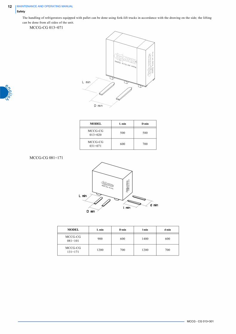
The handling of refrigerators equipped with pallet can be done using fork-lift trucks in accordance with the drawing on the side; the lifting
can be done from all sides of the unit.
MCCG-CG 013÷071
MCCG-CG 081÷171
MODEL L min D min
MCCG-CG 013÷020
500 580
MCCG-CG 031÷071
600 700
MODEL L min D min l min d min
MCCG-CG 081÷101
900 600 1400 600
MCCG-CG 131÷171
1200 700 1200 700
MCCG - CG 013÷301
13MAINTENANCE AND OPERATING MANUAL
Safety
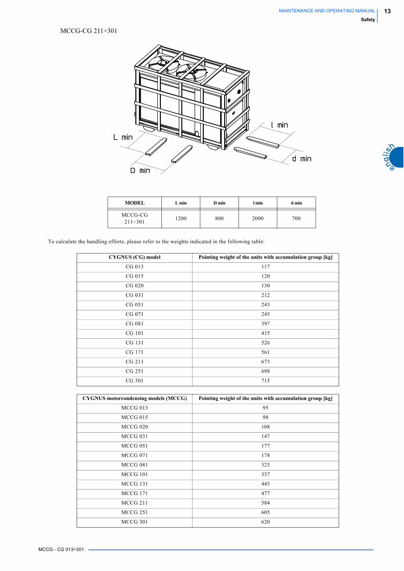
MCCG-CG 211÷301
To calculate the handling efforts, please refer to the weights indicated in the following table:
MODEL L min D min l min d min
MCCG-CG 211÷301
1200 800 2000 700
CYGNUS (CG) model Pointing weight of the units with accumulation group [kg]
CG 013 117
CG 015 120
CG 020 130
CG 031 212
CG 051 243
CG 071 245
CG 081 397
CG 101 415
CG 131 526
CG 171 561
CG 211 673
CG 251 698
CG 301 715
CYGNUS motorcondensing models (MCCG) Pointing weight of the units with accumulation group [kg]
MCCG 013 95
MCCG 015 98
MCCG 020 108
MCCG 031 147
MCCG 051 177
MCCG 071 178
MCCG 081 323
MCCG 101 337
MCCG 131 445
MCCG 171 477
MCCG 211 584
MCCG 251 605
MCCG 301 620

MCCG - CG 013÷301
14 MAINTENANCE AND OPERATING MANUAL
Safety
3.2.3 Instal lat ion precautionsFor the connection to the electrical net see chapter Chapter 6 “Installation”.
3.2.4 Precautions during operationOperation must be carried out by competent personnel under a qualified supervisor.
All the water piping must be painted or clearly marked in accordance with local safety regulations in the place of installation.
Never remove or tamper with the safety devices, guards or insulation materials fitted to the unit or auxiliary equipment.
All electrical connections must comply with local codes.
The unit and auxiliary equipment must be earthen and protected by fuses against short-circuits and overloading.
When mains power is switched on, lethal voltages are present in the electrical circuits and extreme caution must be exercised whenever it is
necessary to carry out any work on the electrical system.
Do not open any electrical panels or cabinets or touch any electrical components or associated equipment while voltage is applied unless it is
necessary for measurements, tests or adjustments.
Such work should be carried out only by a qualified electrician equipped with the proper tools and wearing appropriate body protection
against electrical hazards.
3.2.5 Maintenance and repair precautionsMaintenance, overhaul and repair work must be carried out by competent personnel under a qualified supervisor.
When disposing of parts and waste material of any kind make sure that there is no pollution of any drain or natural water-course and that no
burning of waste takes place which could cause pollution of the air.
Protect the environment by using only approved methods of disposal.
If replacement parts are needed use only original spares.
Keep a written record of all maintenance and repair work carried out on the unit and auxiliary equipment.
The frequency and the nature of the work required over a period can reveal adverse operating conditions which should be corrected.
Use only refrigerant gas specified on the specification plate of the unit.
Make sure that all instructions concerning operation and maintenance are strictly followed and that the complete unit, with all accessories
and safety devices, is kept in good working order.
The accuracy of pressure and temperature gauges must be regularly checked.
They must be renewed when acceptable tolerances are exceeded.
Keep the machine clean at all times.
Protect components and exposed openings by covering them, for example, with clean cloth or tape during maintenance and repair work.
Do not weld or carry out any operation which produces heat near a system which contains oil or flammable liquids.
The systems which may contain oil or flammable liquids must be completely drained and cleaned (with steam, for example), before carrying
out these operations.
Never weld, nor modify in any way, a vessel which may be put under pressure.
To prevent an increase in working temperature, inspect and clean heat exchanging surfaces (i.e. condenser fins) regularly. For every unit
establish a suitable time schedule for cleaning operations.
Avoid to damage the safety valves and other pressure relief devices.
Avoid plugging by paint, oil or dirt accumulation.
Precautions must be taken when carrying out welding or any repair operation which generates heat, flames or sparks.
The adjacent components must always be screened with non-flammable material and if the operation is to be carried out near any part of the
lubrication system, or close to a component which may contain oil, the system must first be thoroughly purged, preferably by steam cleaning.
Never use a light source with an open flame to inspect any part of the machine.
Before dismantling any part of the unit ensure that all heavy movable parts are secured.
When a repair has been completed, make sure no tools, loose parts or rags are left in, or on the machine.
Check the direction of rotation of electric motors (the pump if installed) when starting up the unit initially and after any work on the
electrical connections or switch gear.
All guards must be reinstated after carrying out repair or maintenance work.
Do not use flammable liquid to clean any component during operation.If chlorinated hydrocarbon non-flammable fluids are used for cleaning, safety precautions must be taken against any toxic vapours which
may be released.
ATTENTIONBefore removing any panels or dismantling any part of the unit, carry out the following operations:- Isolate the unit from the main electrical power supply by disconnecting the cable from the electrical power source.- Lock the isolator in the “OFF” position with a lock.- Attach a warning label to the main isolator switch conveying: “WORK IN PROGRESS - DON NOT APPLY VOLTAGE”.- Do not switch on electrical power or attempt to start the unit if a warning label is attached.
3 . 3 R e f r i g e r a n t g a s e sR407c is used as refrigerant in these units.
Never attempt to mix refrigerant gases.To clean out a very heavily contaminated refrigerant system, e.g. after a refrigerant compressor burnout, a qualified refrigeration engineer
must be consulted to carry out the task.
MCCG - CG 013÷301
15MAINTENANCE AND OPERATING MANUAL
Safety
The manufacturer's instructions and local safety regulations should always be observed when handling and storing high pressure gas
cylinders.
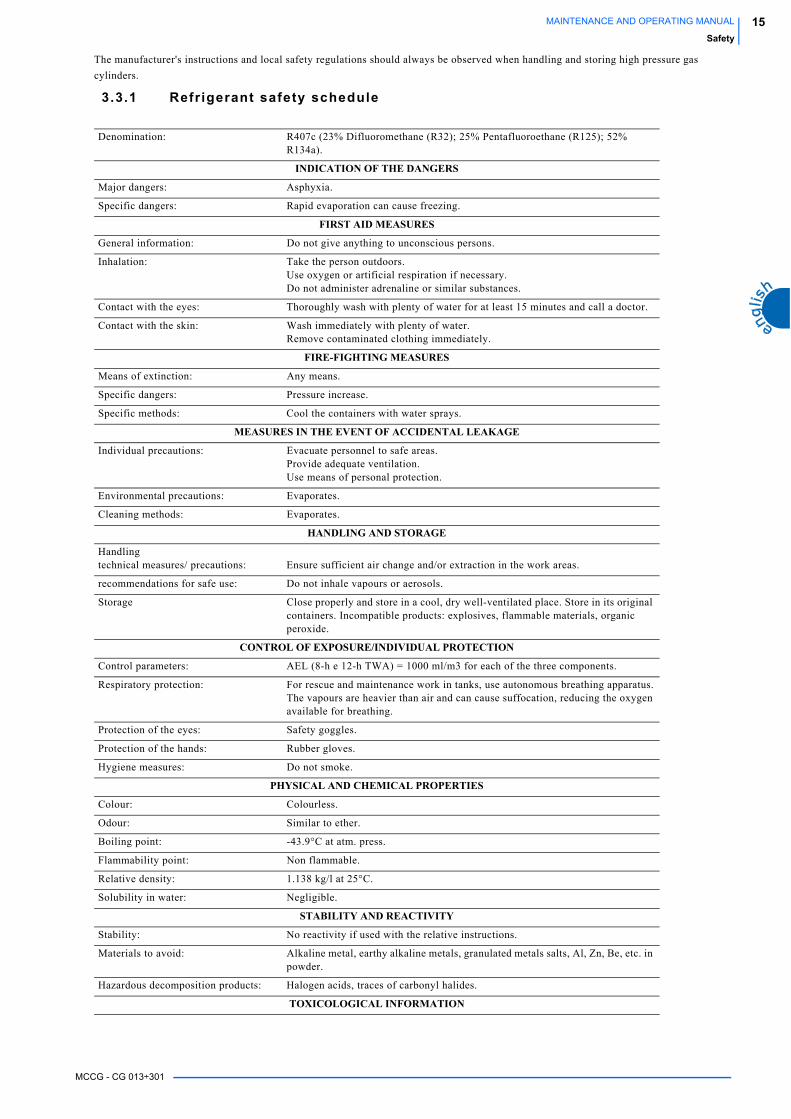
3.3.1 Refrigerant safety schedule
Denomination: R407c (23% Difluoromethane (R32); 25% Pentafluoroethane (R125); 52% R134a).
INDICATION OF THE DANGERS
Major dangers: Asphyxia.
Specific dangers: Rapid evaporation can cause freezing.
FIRST AID MEASURES
General information: Do not give anything to unconscious persons.
Inhalation: Take the person outdoors.Use oxygen or artificial respiration if necessary.Do not administer adrenaline or similar substances.
Contact with the eyes: Thoroughly wash with plenty of water for at least 15 minutes and call a doctor.
Contact with the skin: Wash immediately with plenty of water.Remove contaminated clothing immediately.
FIRE-FIGHTING MEASURES
Means of extinction: Any means.
Specific dangers: Pressure increase.
Specific methods: Cool the containers with water sprays.
MEASURES IN THE EVENT OF ACCIDENTAL LEAKAGE
Individual precautions: Evacuate personnel to safe areas.Provide adequate ventilation.Use means of personal protection.
Environmental precautions: Evaporates.
Cleaning methods: Evaporates.
HANDLING AND STORAGE
Handlingtechnical measures/ precautions: Ensure sufficient air change and/or extraction in the work areas.
recommendations for safe use: Do not inhale vapours or aerosols.
Storage Close properly and store in a cool, dry well-ventilated place. Store in its original containers. Incompatible products: explosives, flammable materials, organic peroxide.
CONTROL OF EXPOSURE/INDIVIDUAL PROTECTION
Control parameters: AEL (8-h e 12-h TWA) = 1000 ml/m3 for each of the three components.
Respiratory protection: For rescue and maintenance work in tanks, use autonomous breathing apparatus.The vapours are heavier than air and can cause suffocation, reducing the oxygen available for breathing.
Protection of the eyes: Safety goggles.
Protection of the hands: Rubber gloves.
Hygiene measures: Do not smoke.
PHYSICAL AND CHEMICAL PROPERTIES
Colour: Colourless.
Odour: Similar to ether.
Boiling point: -43.9°C at atm. press.
Flammability point: Non flammable.
Relative density: 1.138 kg/l at 25°C.
Solubility in water: Negligible.
STABILITY AND REACTIVITY
Stability: No reactivity if used with the relative instructions.
Materials to avoid: Alkaline metal, earthy alkaline metals, granulated metals salts, Al, Zn, Be, etc. in powder.
Hazardous decomposition products: Halogen acids, traces of carbonyl halides.
TOXICOLOGICAL INFORMATION

MCCG - CG 013÷301
16 MAINTENANCE AND OPERATING MANUAL
Safety
Acute toxicity: (R32) LC50/inhalation/4 hours/lab. rats >760 ml/l(R125) LC50/inhalation/4 hours/lab. rats >3480 mg/l(R134a) ALC/inhalation/4 hours/lab. rats = 567 ml/l.
Local effects: Concentrations substantially above the TLV can cause narcotic effects.Inhalation of products in decomposition can lead to respiratory difficulty (pulmonary oedema).
Long-term toxicity: Has not shown any cancerogenic, teratogenic or mutagenic effects in experiments on animals.
ECOLOGICAL INFORMATION
Global warming potential HGWP (R11=1):
R125: 0.84 - R134a: 0.28
Ozone depletion potential ODP (R11=1):
0
Considerations on disposal: Usable with reconditioning.
MCCG - CG 013÷301
17MAINTENANCE AND OPERATING MANUAL
Technical data
CHAPTER 4
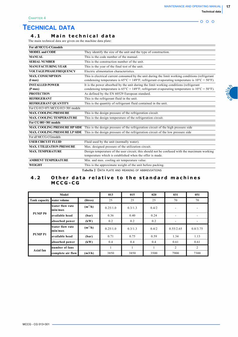
TECHNICAL DATA4 . 1 M a i n t e c h n i c a l d a t a
The main technical data are given on the machine data plate:
4 . 2 O t h e r d a t a r e l a t i v e t o t h e s t a n d a r d m a c h i n e s M C C G - C G
For all MCCG-CGmodelsMODEL and CODE They identify the size of the unit and the type of construction.
MANUAL This is the code number of the manual.
SERIAL NUMBER This is the construction number of the unit.
MANUFACTURING YEAR This is the year of the final test of the unit.
VOLTAGE/PHASE/FREQUENCY Electric alimentation characteristics.
MAX. CONSUMPTION(I max)
This is electrical current consumed by the unit during the limit working conditions (refrigerant condensing temperature is 65°C = 149°F; refrigerant evaporating temperature is 10°C = 50°F).
INSTALLED POWER(P max)
It is the power absorbed by the unit during the limit working conditions (refrigerant condensing temperature is 65°C = 149°F; refrigerant evaporating temperature is 10°C = 50°F).
PROTECTION As defined by the EN 60529 European standard.
REFRIGERANT This is the refrigerant fluid in the unit.
REFRIGERANT QUANTITY This is the quantity of refrigerant fluid contained in the unit.
For CG 013÷071 MCCG 013÷301 models
MAX. COOLING PRESSURE This is the design pressure of the refrigeration circuit.
MAX. COOLING TEMPERATURE This is the design temperature of the refrigeration circuit.
For CG 081÷301 modelsMAX. COOLING PRESSURE HP SIDE This is the design pressure of the refrigeration circuit of the high pressure side
MAX. COOLING PRESSURE LP SIDE This is the design pressure of the refrigeration circuit of the low pressure side
For all MCCG-CGmodels
USER CIRCUIT FLUID Fluid used by the unit (normally water).
MAX. UTILIZATION PRESSURE Max. designed pressure of the utilization circuit.
MAX. TEMPERATURE Design temperature of the user circuit; this should not be confused with the maximum working temperature which is established when the offer is made.
AMBIENT TEMPERATURE Min. and max. cooling air temperature value.
WEIGHT This is the approximate weight of the unit before packing.
Tabella 2 DATA PLATE AND MEANING OF ABBREVIATIONS
Model 013 015 020 031 051
Tank capacity water volume (litres) 25 25 25 70 70
PUMP P0
water flow ratemin/max
(m3/h) 0.25/1.0 0.3/1.3 0.4/2 - -
available head (bar) 0.36 0.40 0.24 - -
absorbed power (kW) 0.2 0.2 0.2 - -
PUMP P1
water flow ratemin/max
(m3/h) 0.25/1.0 0.3/1.3 0.4/2 0.55/2.65 0.8/3.75
available head (bar) 0.71 0.75 0.59 1.34 1.13
absorbed power (kW) 0.4 0.4 0.4 0.61 0.61
Axial fannumber of fans 1 1 1 2 2
complete air flow (m3/h) 3850 3850 3500 7900 7300
MCCG - CG 013÷301
18 MAINTENANCE AND OPERATING MANUAL
Technical data
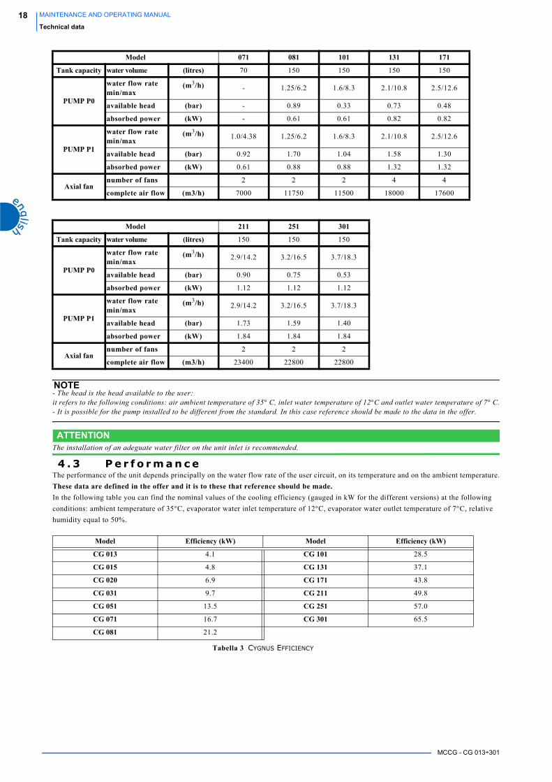
NOTE- The head is the head available to the user:it refers to the following conditions: air ambient temperature of 35° C, inlet water temperature of 12°C and outlet water temperature of 7° C.- It is possible for the pump installed to be different from the standard. In this case reference should be made to the data in the offer.
ATTENTIONThe installation of an adeguate water filter on the unit inlet is recommended.
4 . 3 P e r f o r m a n c eThe performance of the unit depends principally on the water flow rate of the user circuit, on its temperature and on the ambient temperature.
These data are defined in the offer and it is to these that reference should be made.In the following table you can find the nominal values of the cooling efficiency (gauged in kW for the different versions) at the following
conditions: ambient temperature of 35°C, evaporator water inlet temperature of 12°C, evaporator water outlet temperature of 7°C, relative
humidity equal to 50%.
Model 071 081 101 131 171
Tank capacity water volume (litres) 70 150 150 150 150
PUMP P0
water flow ratemin/max
(m3/h) - 1.25/6.2 1.6/8.3 2.1/10.8 2.5/12.6
available head (bar) - 0.89 0.33 0.73 0.48
absorbed power (kW) - 0.61 0.61 0.82 0.82
PUMP P1
water flow ratemin/max
(m3/h) 1.0/4.38 1.25/6.2 1.6/8.3 2.1/10.8 2.5/12.6
available head (bar) 0.92 1.70 1.04 1.58 1.30
absorbed power (kW) 0.61 0.88 0.88 1.32 1.32
Axial fannumber of fans 2 2 2 4 4
complete air flow (m3/h) 7000 11750 11500 18000 17600
Model 211 251 301
Tank capacity water volume (litres) 150 150 150
PUMP P0
water flow ratemin/max
(m3/h) 2.9/14.2 3.2/16.5 3.7/18.3
available head (bar) 0.90 0.75 0.53
absorbed power (kW) 1.12 1.12 1.12
PUMP P1
water flow ratemin/max
(m3/h) 2.9/14.2 3.2/16.5 3.7/18.3
available head (bar) 1.73 1.59 1.40
absorbed power (kW) 1.84 1.84 1.84
Axial fannumber of fans 2 2 2
complete air flow (m3/h) 23400 22800 22800
Model Efficiency (kW) Model Efficiency (kW)
CG 013 4.1 CG 101 28.5
CG 015 4.8 CG 131 37.1
CG 020 6.9 CG 171 43.8
CG 031 9.7 CG 211 49.8
CG 051 13.5 CG 251 57.0
CG 071 16.7 CG 301 65.5
CG 081 21.2
Tabella 3 CYGNUS EFFICIENCY

MCCG - CG 013÷301
19MAINTENANCE AND OPERATING MANUAL
Technical data
In the following table you can find the nominal values of the cooling efficiency (gauged in kW for the different versions) at the following
conditions: ambient temperature of 35°C and at evaporation temperature of 5°C.
Model Efficiency (kW) Model Efficiency (kW)
MCCG 013 4.3 MCCG 101 30.2
MCCG 015 5.1 MCCG 131 39.5
MCCG 020 7.4 MCCG 171 46.4
MCCG 031 10.4 MCCG 211 52.8
MCCG 051 14.8 MCCG 251 60.7
MCCG 071 17.8 MCCG 301 69.9
MCCG 081 22.4
Tabella 4 MCCYGNUS EFFICIENCY

MCCG - CG 013÷301
20 MAINTENANCE AND OPERATING MANUAL
Technical data

MCCG - CG 013÷301
21MAINTENANCE AND OPERATING MANUAL
Description
CHAPTER 5
DESCRIPTIONATTENTION
The following information refer only to the CG models, because the motocondensing units are not equipped with evaporator, pump and hydraulic group.
5 . 1 G e n e r a l Cygnus range are monobloc units air condensed equipped with:
-hermetic compressors
- hydraulic group made up of a plate-type evaporator, an accumulation tank, a circulator or a pump (it depends on the model)
- a condenser made up a fin battery and axials fans.
Each chiller is equipped with a microprocessor control that manages the main functions of the unit such as the regulations, the alarms and the
user interface.
The units use R407C.
The components used for these machines are of high quality and all the projecting process, from the production to the unit checking, has
been manufactured in conformity with ISO 9001 norms.
5 . 2 O p e r a t i n g p r i n c i p l eAll the units described in this manual work on the basis of the same principle.
A refrigerant circuit, according to the operating modality (summer or winter), cools or heat the surfaces of a tube plate evaporator, where in
one side the refrigerant fluid evaporates and in the other side the liquid to be cooled flows.
The refrigerant compressor is managed by an electronic control that checks the water inlet temperature to the machine in order to keep the
outlet temperature inside the set limits.
5 . 3 M a t e r i a l sThe data relating to the materials refer to standard machines.
In case of particular units special materials are used, so it is necessary to refer to the data on the offer.
5.3.1 CasingThe whole base, risers, panels are in galvanised carbon steel sheet fixed together with screws.
All the sheets are phospho-degreasing treated and painted with polyester-powders.
The structure has been designed for the easy access to all the unit components.
In all units the compressor site is covered with sound-absorbent material to reduce the unit noise.
5.3.2 Materials in contact with the l iquid of the user circuitPlate evaporator in stainless steel, braze welded with copper, tank in carbon steel, copper tubes.
5 . 4 C o m p o n e n t sThe data relating to the components refer to standard machines.
In case of particular units special materials are used, so it is necessary to refer to the data on the offer.
5.4.1 Compressors
The MCCG-CG 013÷020 units are equipped with a Rotary compressor of hermetic type, while the MCCG-CG 031÷301units are equipped
with a Scroll compressor of hermetic type. The MCCG-CG 171 models have one compressor, while the MCCG-CG 211÷301 models have
two tandem compressors.
These components are positioned in the compressor site, sound isolated with a sound-absorbent mattress of 15÷20 mm thickness positioned
on the side panels, compressor site - fan site separating panel and compressor site closing front panel.
MCCG-CG 013÷071 MCCG-CG 081÷171 MCCG-CG 211÷301

MCCG - CG 013÷301
22 MAINTENANCE AND OPERATING MANUAL
Description
5.4.2 Condenser
Consisting of a fin-pack battery with aluminium fins, copper tubes and shoulders in galvanised sheet.
The condenser batteries (B) have been calculated, dimensioned and designed by means of modern computerised design technics.
A good subcooling completes the total efficiency increasing the unit final COP (Coefficient Of Performance = cooling capacity/absorbed
power).
5.4.3 Evaporator (only CG models)
Plate evaporator in stainless steel, braze welded with copper, tank in carbon steel, copper tubes. It is positioned inside the compressor
compartment in all models.
If requested, the compressor can be furnished with an antifreeze resistance, to prevent risks of freezing, see paragraph 5.4.6 “Antifreeze resistance”.
NOTEThe motocondensing versions MCCG are not equipped with the evaporator, but it must be installed a remote one. This operation have to becarried out by qualified personnel. For further information see paragraph 5.7.3 “Refrigerant circuit for motocondensing version”.
5.4.4 Fan/sAll units are equipped with axial fans.
The MCCG-CG 013÷071 and MCCG-CG 131÷171 units are equipped with fans which have vanes made up of plastic material, while the
MCCG-CG 081÷101 and MCCG-CG 211÷301units are equipped with fan switch made up of aluminium sickle profile shovels.
The MCCG-CG 013÷071 units are equipped with conveyors made up of radiused polystyrene, while the MCCG-CG 081÷301 units are
furnished with a nozzle notched in the cover plate.
All units can be furnished with an electronic regulator for the fans, more over only the MCCG-CG 013÷020 models can be furnished even
with ON/OFF step regulation.
Up to the MCCG-CG 171 model the units are equipped with a single-phase fan, while MCCG-CG 201÷301 units are equipped with three-
phases fans.
The protection rating is IPX4 and it has F insulation class to assure the external working with all types of climates. The assembly is
completed with an external safety protection grill.
MCCG-CG 013÷020 MCCG-CG 031÷071 MCCG-CG 081÷301
MCCG-CG 013÷020 MCCG-CG 031÷071 MCCG-CG 081÷301

MCCG - CG 013÷301
23MAINTENANCE AND OPERATING MANUAL
Description
5.4.5 Hydraulic group (only CG models)The CG may have three different configurations:
• without hydraulic group
• with hydraulic group and P0 pump
• with hydraulic group and P1 pump
These options can be choose during the offer.
The hydraulic group is composed by:
• tank;
• pump / circulator;
• drainage/filling valve;
• manual bleed valve;
• expansion tank of an adequate volume;
• 3 barg safety valve;
• water pressure gauge positioned on the pump outlet, in order to check the preloaded pressure of the plant (when the chiller is
off) and the pump outlet pressure (when the chiller in on);
• differential pressure switch, positioned on the evaporator, that will stop the compressor if the water will not flow through
the hydraulic side;
For the data concerning the pump and the tank see the paragraph 4.2 “Other data relative to the standard machines MCCG-CG”
5.4.6 Antifreeze resistanceThe CG units can be equipped with a antifreeze resistance, if requested.
It is composed by a resistance wounded around the evaporator, the tank and the pump (but in the motocondensing units).
The resistance is checked by the electronic board, and its function is to prevent the components of the unit against the risk of freezing, when
the temperature is lower than 0°C.
The logic and therm regulation parameter are described in the Chapter 8 “Electronic Board”).
5 . 5 O v e r a l l d i m e n s i o nSee enclosures.
5 . 6 M i n i m u m d i s t a n c e s f r o m w a l l s i n t h e i n s t a l l a t i o n a m b i e n t
See enclosures.
5 . 7 W a t e r a n d r e f r i g e r a n t c i r c u i t s(See enclosures)
5.7.1 Water circuit (only CG models)See 5.4.5 “Hydraulic group (only CG models)”If the unit is not equipped with the hydraulic group, the water circuit is composed only with a plate type heat exchanger.
The following description refers to the unit complete of hydraulic group.
The water enters the unit, passes through the tank and, during evaporation phase, exchanges heat with the refrigerant fluid inside the plate
type heat exchanger.
The water is sucked by a centrifugal pump [36], directly connected to the use water circuit.
At the pump outlet is connected a water pressure switch [70] positioned on the unit back site over the water connections. It indicates the
water pressure at the plant outlet.
Between the evaporator inlet and outlet tubes there is a water differential pressure switch that protects the evaporator during water lacks.
ATTENTIONThe installation of the water filter is recommended. It must be connected to the inlet tube.
5.7.2 Refrigerant circuit (only CG models)The refrigerant is pumped by the hermetic type refrigerant compressor into the condenser.
The condenser is a fin-pack type heat exchanger and is cooled by an air-flow produced by one or two fans according to the unit model.
The condenser fan(s) is/are controlled by a regulator which regulates their speed according to the condensing temperature by means of a
pressure probe positioned on the coil. For the smaller models CG013÷020 you can set the ON/OFF regulation.
After the condenser, the refrigerant liquid passes through:
• a capillary completed with drying filter for models CG 013÷020
• a drying filter, a flow indicator and a thermostat valve from model CG 031 and upper.
The refrigerant then enters the plate type evaporator.
When it exits the evaporator, the refrigerant is again sucked by the compressor and the cycle repeats itself.
All solderings for connecting the refrigerant circuit components are made with silver alloy.
5.7.3 Refrigerant circuit for motocondensing versionThe motocondensing units MCCG have no evaporator and thermostatic valve, that have to be installed by the customer/installer.
It has been added two cocks (one in the liquid line, and one in the compressor sucking line) and a solenoid valve in the liquid line.
MCCG - CG 013÷301
24 MAINTENANCE AND OPERATING MANUAL
Description
ATTENTIONThe completing of the installation must be carried out by the customer/installer.The sizing and building of the cooling lines that connect the motocondensing units and the motoevaporant units is very important, and so it must be carried out by qualified personnel.
For the installation see 6.7 “Cooling circuit connections in motocondensing units”.
Once the remote evaporator has been installed, the MCCG units will work as described in paragraph 5.7.2 “Refrigerant circuit (only CG models)”.
5 . 8 E l e c t r i c a l c i r c u i tSee annexes.
MCCG - CG 013÷301
25MAINTENANCE AND OPERATING MANUAL
Installation
CHAPTER 6
INSTALLATIONATTENTION
Before carrying out the installation or operating on this machine, ensure that all the personnel has read and understood the Chapter 3 “Safety”.
6 . 1 I n s p e c t i o nImmediately after uncrating, inspect the unit.
6 . 2 P o s i t i o n i n g1. The unit may be installed both outdoors and indoors.
2. If installed indoors, the room must be well ventilated. In some cases it may be necessary to install fans or extractors to limit the
temperature of the room.
3. The ambient air must be clean and not contain flammable gas or solvents.
4. The minimum and maximum working ambient temperature are specified on the unit data plate. In extreme temperature
conditions, the protection devices may trip.
5. The machine must be positioned on any flat surface capable of supporting its weight.
6. Leave at least one metre around the unit to permit access during service operations (see chapter 5.4.6 “Overall dimension”).
7. Do not obstruct or disturb the condenser's flow of thermal exchanging air.
8. Position the unit in such a way that the thermal exchanging air cannot recirculate in the intake grilles.
9. Ensure that the unit is not subject to warm air from the cooling systems of other machines.
6 . 3 A n t i f r e e z e p r o t e c t i o nEven if the minimum working ambient temperature is above 0°C it is possible for the machine - during stoppages in the cold seasons - to find
itself in an environment with a temperature below 0°C.
In these cases, if the machine is not emptied, antifreeze (ethylene glycol) must be added in the following percentages to prevent the
formation of ice:
ATTENTIONThe antifreeze protection can be performed also following the indications in paragraph 10.2.2 “Water circuit emptying” or, if requested, by an antifreeze resistance, operating as described in Chapter 8 “Electronic Board”.
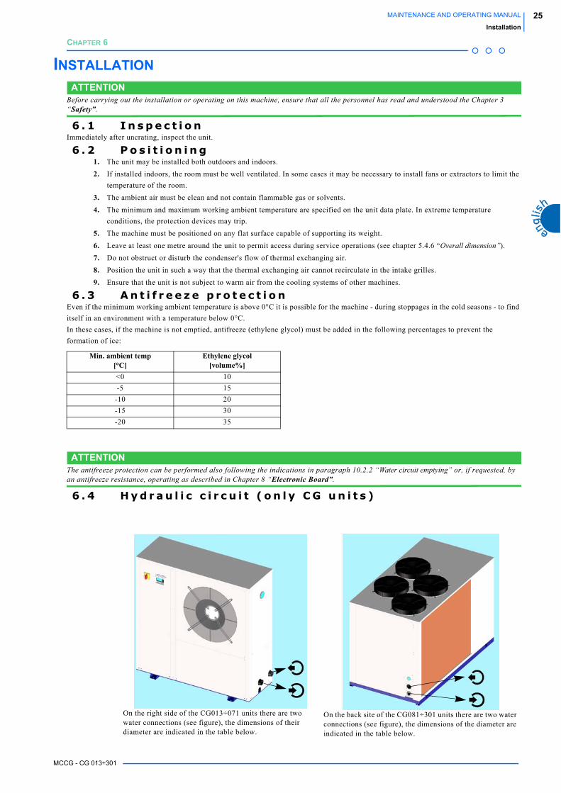
6 . 4 H y d r a u l i c c i r c u i t ( o n l y C G u n i t s )
Min. ambient temp[°C]
Ethylene glycol[volume%]
<0 10
-5 15
-10 20
-15 30
-20 35
On the right side of the CG013÷071 units there are two water connections (see figure), the dimensions of their diameter are indicated in the table below.
On the back site of the CG081÷301 units there are two water connections (see figure), the dimensions of the diameter are indicated in the table below.

MCCG - CG 013÷301
26 MAINTENANCE AND OPERATING MANUAL
Installation
1. Connect the unit to the water pipelines respecting the water flow direction as indicated in the figures above or in the annexed
overall dimension drawings.
2. Provide two cocks (one at the inlet and one at the outlet) for excluding the unit when maintaining without emptying the user
water circuit.
3. Fill the tank (if present) with water using:
a remote discharge system.
in this case it is necessary to leak manually the air from the tank by operating on the manual valve (*).
If there are frequent air infiltrations into the water circuit it is advisable to install an automatic bleed valve.
4. If the unit is without pump, be sure that the pump installed by the user has the aspiration directly connected to the machine so
that the pressure into the tank is not too high (0.5 bar suggested)
(*): Assure (by checking on the pressure gauge the tank pressure with pump stopped) that the pressure into the water circuit is about 0.5 bar
to avoid that the pump during its operation puts in depression the tank by causing the possible air entering and however to obstacle the use of
manual or automatic air vent systems.
ATTENTIONThe installation of a water filter is recommended connected to the inlet pipeline.
The hydraulic plant must be dimensioned so that the pressure values of the water flow into the unit are not higher than those indicated in the
table below:
6 . 5 E x p a n s i o n t a n kThe models from CG 006 to CG 016 are equipped with an expansion tank.
All other models are furnished with expansion tank (only if required) when the hydraulic group is installed.
If the installation is made by the client or if it is necessary to install a supplementary expansion tank, this must always be connected at the
pump inlet.
To calculate the minimum volume of the expansion tank required for a given installation, the formula below cab be used and is valid if the
pressure is less than or equal to 0.5 bar when the pump is stopped and the maximum working pressure of the expansion tank is greater than or
equal to 4 bar.
The volume of the expansion tank V in litres is given by the formula:
where:
Model IN/OUT water connections diameter
Max. pressure [bar]Units with tank
Max. pressure [bar]Units without tank
CG 013 1” 3 6
CG 015 1” 3 6
CG 020 1” 3 6
CG 031 1” 3 6
CG 051 1” 3 6
CG 071 1” 3 6
CG 081 1 1/4” 3 6
CG 101 1 1/4” 3 6
CG 131 1 1/2” 3 6
CG 171 1 1/2” 3 6
CG 211 2” 3 6
CG 251 2” 3 6
CG 301 2” 3 6
Vt= total volume of the circuit in litres
Ptmin= specific weight at the minimum temperature obtainable by water over the year in °C (even with the plant stopped)
Ptmax= specific weight at the maximum temperature obtainable by water over the year in °C (even with the plant stopped)
V 2 Vt Ptmin Ptmax–( )⋅ ⋅=
MCCG - CG 013÷301
27MAINTENANCE AND OPERATING MANUAL
Installation
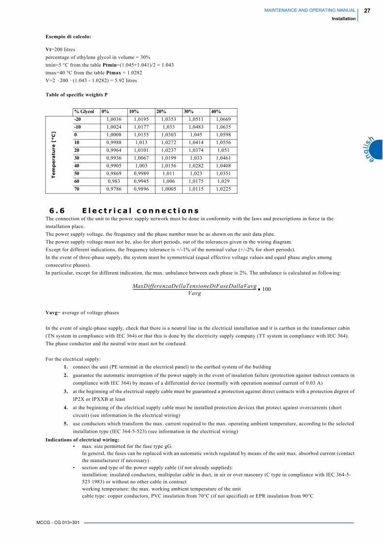
Esempio di calcolo:
Vt=200 litres
percentage of ethylene glycol in volume = 30%
tmin=5 °C from the table Ptmin=(1.045+1.041)/2 = 1.043
tmax=40 °C from the table Ptmax = 1.0282
V=2 · 200 · (1.043 - 1.0282) = 5.92 litres
Table of specific weights P
6 . 6 E l e c t r i c a l c o n n e c t i o n sThe connection of the unit to the power supply network must be done in conformity with the laws and prescriptions in force in the
installation place.
The power supply voltage, the frequency and the phase number must be as shown on the unit data plate.
The power supply voltage must not be, also for short periods, out of the tolerances given in the wiring diagram.
Except for different indications, the frequency tolerance is +/-1% of the nominal value (+/-2% for short periods).
In the event of three-phase supply, the system must be symmetrical (equal effective voltage values and equal phase angles among
consecutive phases).
In particular, except for different indication, the max. unbalance between each phase is 2%. The unbalance is calculated as following:
Vavg= average of voltage phases
In the event of single-phase supply, check that there is a neutral line in the electrical installation and it is earthen in the transformer cabin
(TN system in compliance with IEC 364) or that this is done by the electricity supply company (TT system in compliance with IEC 364).
The phase conductor and the neutral wire must not be confused.
For the electrical supply:
1. connect the unit (PE terminal in the electrical panel) to the earthed system of the building
2. guarantee the automatic interruption of the power supply in the event of insulation failure (protection against indirect contacts in
compliance with IEC 364) by means of a differential device (normally with operation nominal current of 0.03 A)
3. at the beginning of the electrical supply cable must be guaranteed a protection against direct contacts with a protection degree of
IP2X or IPXXB at least
4. at the beginning of the electrical supply cable must be installed protection devices that protect against overcurrents (short
circuit) (see information in the electrical wiring)
5. use conductors which transform the max. current required to the max. operating ambient temperature, according to the selected
installation type (IEC 364-5-523) (see information in the electrical wiring)
Indications of electrical wiring:• max. size permitted for the fuse type gG.
In general, the fuses can be replaced with an automatic switch regulated by means of the unit max. absorbed current (contact
the manufacturer if necessary)
• section and type of the power supply cable (if not already supplied):
installation: insulated conductors, multipolar cable in duct, in air or over masonry (C type in compliance with IEC 364-5-
523 1983) or without no other cable in contract
working temperature: the max. working ambient temperature of the unit
cable type: copper conductors, PVC insulation from 70°C (if not specified) or EPR insulation from 90°C
% Glycol 0% 10% 20% 30% 40%
Te
mp
era
ture
[°C
]
-20 1,0036 1,0195 1,0353 1,0511 1,0669
-10 1,0024 1,0177 1,033 1,0483 1,0635
0 1,0008 1,0155 1,0303 1,045 1,0598
10 0,9988 1,013 1,0272 1,0414 1,0556
20 0,9964 1,0101 1,0237 1,0374 1,051
30 0,9936 1,0067 1,0199 1,033 1,0461
40 0,9905 1,003 1,0156 1,0282 1,0408
50 0,9869 0,9989 1,011 1,023 1,0351
60 0,983 0,9945 1,006 1,0175 1,029
70 0,9786 0,9896 1,0005 1,0115 1,0225
MaxDifferenzaDellaTensioneDiFaseDallaVavgVavg
-------------------------------------------------------------------------------------------------------------------------------- 100•

MCCG - CG 013÷301
28 MAINTENANCE AND OPERATING MANUAL
Installation
The harness of the power supply cable is made by the client.
Remove the control board and the unit front panel (see paragraph 10.2.1 “Unit access”).
Flow the cable through the fairlead positioned in the low part of the left side panel by pulling it in the inside part of the compressor site.
Remove the sheath from the cable and flow it through the appropriate grilles under the electrical panel (see figure).
Wire the cable on the general switch-breaker as indicated in the figure below and in the electrical wiring annexed to the unit.
ATTENTIONTo check the electrical connection of the unit to the electrical wiring see Chapter 7 “Start up”.
6 . 7 C o o l i n g c i r c u i t c o n n e c t i o n s i n m o t o c o n d e n s i n g u n i t s
The motocondensing units MCCG are not equipped with the evaporator, the installation must be carried out by the customer/installer.
ATTENTIONThe sizing and building of the cooling lines that connect the motocondensing units and the motoevaporant units is very important, and so it must be carried out by qualified personnel.
The table below shows the dimensions of the connections (they are the same for the piping that have to be used), and the maximum distance
between the motocondensing and the motoevaporant unit.
The MCCG units are furnished with a small charge of R407C, that will have to be completed during the installation, by a refrigerator
technician.
The charge is complete when:
• The liquid indicator does not signal bubbles
• The overheating of the sicked gas is 4-8°K
• The sub-cooling of the liquid is 3-5°K
ATTENTIONThe evaporator water inlet/outlet (BEWIT/BEWOT) temperature probes are furnished with the machine, their installation must be carried out by the customer/installer.
On the right side of the MCCG 013÷071 units there are two freon connections (see figure) that have to be welded, the dimensions of their diameter are indicated in the table below.
On the back site of the MCCG 081÷301 units there are two freon connections (see figure) that have to be welded, the dimensions of their diameter are indicated in the table below.
Unit MCCG013
MCCG015
MCCG020
MCCG031
MCCG051
MCCG071
MCCG081
MCCG101
MCCG131
MCCG171
MCCG211
MCCG251
MCCG301
Suction line diameter
[mm] Ø 12 Ø 16 Ø 16 Ø 18 Ø 22 Ø 28 Ø 28 Ø 35 Ø 35 Ø 35 Ø 42 Ø 42 Ø 42
Liquid line diameter
[mm] Ø 8 Ø 8 Ø 8 Ø 10 Ø 10 Ø 12 Ø 12 Ø 16 Ø 16 Ø 18 Ø 18 Ø 22 Ø 22
Maximum distance between MCCG
units and motoevaporant
units
[m] 10 15 15 15 20 25 30 30 30 25 25 25 25
Table 5 MCCG CONNECTIONS
FREONOUTLET
FREONINLET
FREONOUTLET
FREONINLET

MCCG - CG 013÷301
29MAINTENANCE AND OPERATING MANUAL
Installation
BEWIT utilized for the temperature regulationBEWOT utilized for the antifreeze functionFor the installation see the annexed diagrams.
ATTENTIONThe maximum distance between the probes is 100m using screened cable.
If the BEWOT probe will not be used (antifreeze probe), it will have to be removed and disconnected from the bornes 5-4 of the electronic
board (for further information see the wiring diagram), set the parameter CF05=0 to make it not enable (to modify the parameter see
paragraphs 8.10 “Programming by keyboard” and 8.18.2 “Configuration parameters”).
If the remote evaporator is already equipped with a temperature control system, the BEWIT and BEWOT probes are not necessary, but you
will have to install the MCCG REMOTE CONTROL KIT. It is composed by two FINDER relays that have to be connected to the
compressor enabling digital inputs. For the installation and the wiring see the diagram enclosed in the KIT.
More over it will be necessary to change the following parameters:
CF02=1, CF04=3, CF05=0, CF07=2, (CF011=6 only MCCG 211÷301 units).
MCCG Unit
Remote evaporator
FREON INLET
FREON OUTLET
H2O
WATERINLET
WATEROUTLET
-BEWIT
-BEWOT
Electronic board
Water differentialpressure switch

MCCG - CG 013÷301
30 MAINTENANCE AND OPERATING MANUAL
Installation

MCCG - CG 013÷301
31MAINTENANCE AND OPERATING MANUAL
Start up
CHAPTER 7
START UPATTENTION
Before starting up these units be sure that all personnel have read and understood the Chapter 3 “Safety”.
1. Check that the machine's on/off valves are open.
2. Check that the tank is completely full of water and properly vented.
The modes equipped with the hydraulic group (optional), it is possible to check on the pressure gauge if the pressure is about 0.5
bar.
Check that the ambient temperature is within the limits indicated on the machine data plate.
3. Check that the main switch is in the OFF position (“O”).
4. Check that the power supply voltage is correct.
5. Power the machine (stand-by unit) by means of the supply line protection device.
6. Press the button for 5 seconds to start up the unit
The led of the icon blinks for 5 sec. and than it lights on.
For further information see Chapter 8 “Unit switching on / off”.
7. In three-phase units MCCG-CG 031÷301, check that compresses works correctly (it must not be noisy or overheated) and check
that the pump (if installed) and the fun (if installed) rotation direction is correct (it have to suck the air from inside the machine).
The machines have been designed in order that these three components would have the some rotation direction. So, if one works
in the right way even the other do.
If the rotation direction is wrong for all the three components, invert two supply phases of the electronic board. If on the
contrary they are not correctly connected, invert the borns phases of the corresponding counter.
8. In the models equipped with the pump (optional), it is possible to check the pressure difference between the value read by the
pressure gauge positioned on the unit back panel with the pump running and the value read with the pump stopped. The
difference must be greater than the available pressure head with maximum pump flow rate.
If this difference is lower, it means that the water flow rate is greater than the permitted maximum value.
To avoid damaging the pump it is necessary to increase the pressure drop in the hydraulic circuit: e.g. partially closing a pump outlet cock (the cock at pump outlet is installed by the client).
9. If with the first start-up, there is a high ambient temperature and the temperature of the water in the hydraulic circuit is much
higher than the working value (e.g. 25-30°C) this means that the machine starts up overloaded with the consequence of possible tripping of the protection devices.
To reduce this overload, a machine outlet valve can be gradually (but not totally!) closed to reduce the flow of water passing through it.Open the valve as the water temperature in the hydraulic circuit reaches the working value.
10. The machine is now ready for operation.
If the thermal load is lower than that produced by the machine, the water temperature drops until it reaches the set-point value
(ST01parameter) set following the indications of chapter Chapter 8 “Electronic Board”.
When ST01 value has been reached, the thermostat controlling the water inlet temperature stops the compressor.
If installed, the water pump continues to run however.

MCCG - CG 013÷301
32 MAINTENANCE AND OPERATING MANUAL
Start up

MCCG - CG 013÷301
33MAINTENANCE AND OPERATING MANUAL
Electronic Board
CHAPTER 8
ELECTRONIC BOARD8 . 1 U s e r i n t e r f a c e8.1.1 Display
The display is divided in 3 zones.
8.1.2 Display icons
Upper-left zone
Generally it displays the evaporator water inlet / outlet temperature.
NOTEThe displaying depends on the setting of parameter CF36 8.11“Values displayed (parameter CF36)”.
Lower-left zone
Condensation temperature / pressure or evaporator water antifreeze
temperature (heat pump water units), with the appropriate unit of
measurement.
NOTEThe displaying depends on the setting of parameter CF36 8.11“Values displayed (parameter CF36)”.
Right zone
Signalling icons.
ICON MEANING ICON MEANINGCelsius degrees (If displayed) Low pressure alarm
Fahrenheit degrees (If not displayed) Antifreeze resistance
Bar/Psi Pump on
Compressor 1 Flow meter alarm
Compressor 2 Time to defrost starting (hour)
Stand-by unit Fan on
General alarm Indication for Function Menu entering
High pressure alarm
MCCG - CG 013÷301
34 MAINTENANCE AND OPERATING MANUAL
Electronic Board
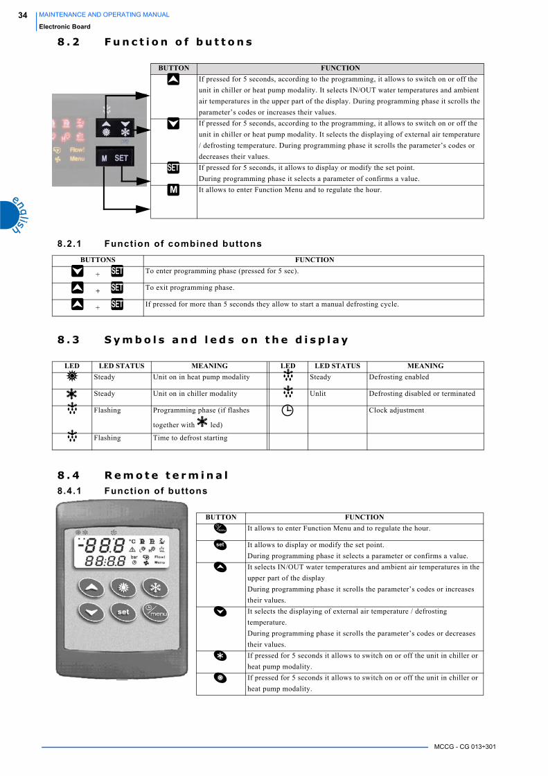
8 . 2 F u n c t i o n o f b u t t o n s
8.2.1 Function of combined buttons
8 . 3 S y m b o l s a n d l e d s o n t h e d i s p l a y
8 . 4 R e m o t e t e r m i n a l8.4.1 Function of buttons
BUTTON FUNCTIONIf pressed for 5 seconds, according to the programming, it allows to switch on or off the
unit in chiller or heat pump modality. It selects IN/OUT water temperatures and ambient
air temperatures in the upper part of the display. During programming phase it scrolls the
parameter’s codes or increases their values.
If pressed for 5 seconds, according to the programming, it allows to switch on or off the
unit in chiller or heat pump modality. It selects the displaying of external air temperature
/ defrosting temperature. During programming phase it scrolls the parameter’s codes or
decreases their values.
If pressed for 5 seconds, it allows to display or modify the set point.
During programming phase it selects a parameter of confirms a value.
It allows to enter Function Menu and to regulate the hour.
BUTTONS FUNCTION
+ To enter programming phase (pressed for 5 sec).
+ To exit programming phase.
+ If pressed for more than 5 seconds they allow to start a manual defrosting cycle.
LED LED STATUS MEANING LED LED STATUS MEANINGSteady Unit on in heat pump modality Steady Defrosting enabled
Steady Unit on in chiller modality Unlit Defrosting disabled or terminated
Flashing Programming phase (if flashes
together with led)
Clock adjustment
Flashing Time to defrost starting
BUTTON FUNCTIONIt allows to enter Function Menu and to regulate the hour.
It allows to display or modify the set point.
During programming phase it selects a parameter or confirms a value.
It selects IN/OUT water temperatures and ambient air temperatures in the
upper part of the display
During programming phase it scrolls the parameter’s codes or increases
their values.
It selects the displaying of external air temperature / defrosting
temperature.
During programming phase it scrolls the parameter’s codes or decreases
their values.
If pressed for 5 seconds it allows to switch on or off the unit in chiller or
heat pump modality.
If pressed for 5 seconds it allows to switch on or off the unit in chiller or
heat pump modality.
MCCG - CG 013÷301
35MAINTENANCE AND OPERATING MANUAL
Electronic Board
If there is no communication between the unit and the remote terminal, in the upper part of the display it appears the message “ ” (no
link).
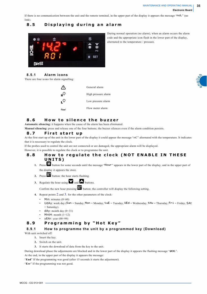
8 . 5 D i s p l a y i n g d u r i n g a n a l a r m
8.5.1 Alarm iconsThere are four icons for alarm signalling:
8 . 6 H o w t o s i l e n c e t h e b u z z e r Automatic silencing: it happens when the cause of the alarm has been eliminated.
Manual silencing: press and release one of the four buttons; the buzzer silences even if the alarm condition persists.
8 . 7 F i r s t s t a r t u pAt the first start up of the unit in the lower part of the display it could appear the message “rtC” alternated with the temperature. It indicates
that it is necessary to regulate the clock.
If the probes used to control the unit are not connected or are damaged, the appropriate alarm will be displayed.
However, it is possible to regulate the clock or to programme the unit.
8 . 8 H o w t o r e g u l a t e t h e c l o c k ( N O T E N A B L E I N T H E S E U N I T S )
1. Press button for some seconds until the message “ ” appears in the lower part of the display, and in the upper part of
the display it appears the store.
2. Press button: the hour starts flashing.
3. Regulate the hour using and buttons.
Confirm the new hour pressing button; the controller will display the following setting.
4. Repeat points 2.and 3. for the other parameters of the clock:
• Min: minutes (0÷60)
• UdAy: week day ( = Sunday, = Monday, = Tuesday, = Wednesday, = Thursday, = Friday, SAt
= Saturday).
• dAy: month day (0÷31)
• MntH: month (1÷12)
• yEAr: year (00÷99)
8 . 9 P r o g r a m m i n g b y “ H o t K e y ”8.9.1 How to programme the unit by a programmed key (Download)
With unit switched off:
1. Insert the key.
2. Switch on the unit.
3. It starts the download of data from the key to the unit.
During download phase the adjustments are blocked and in the lower part of the display it appears the flashing message “dOL”.
At the end, in the upper part of the display it appears the message:
“End” If the programming was good (after 15 seconds it starts the adjustment).
“Err” If the programming was not good.
During normal operation (no alarm), when an alarm occurs the alarm
code and the appropriate icon flash in the lower part of the display,
alternated to the temperature / pressure.
General alarm
High pressure alarm
Low pressure alarm
Flow meter alarm

MCCG - CG 013÷301
36 MAINTENANCE AND OPERATING MANUAL
Electronic Board
8.9.2 How to store the parameters of the unit in the key “UPL”Instrument on:
1. Insert the key.
2. Use or buttons to select the function UPL in the upper part of the display.
3. Press .
It starts the upload of data from the unit to the key.
During upload phase in the lower part of the display it appears the flashing message “UPL”.
At the end of programming phase the following messages appear in the upper part of the display:
“End” If the programming was good.
“Err” If the programming was not good
To exit “UPL” function, press button or wait for time-out.
8 . 1 0 P r o g r a m m i n g b y k e y b o a r dThe parameters of electronic control are divided in two groups and in two levels:
1. USER (Pr1);
2. SERVICCE (Pr2).
USER level allows to access user parameters, SERVICE level allows to access the parameters of unit configuration (it is protected by a
password)
8.10.1 Access to “Pr1” parameters (User level)To enter the menu of “Pr1” parameters which can be access by the user:
1. Press for some seconds + buttons ( and start flashing), in the upper part of the display appears “ALL”, the first
group of parameters.
2. Select the various groups using and buttons.
3. After selecting a group, press button:
if the selected group is part of the selected menu or any parameter of this group has been moved in this menu, in the lower part
of the display it appears the “Label” and the code of the group’s first parameter present in “Pr1”, its value appears in the upper
part of the display.
It will not be possible to enter a parameter’s group which is not part of this menu.
4. It is possible to scroll or modify the parameters contained in the group.
8.10.2 How to modify a parameter’s value1. Enter the programming procedure.
2. Select the desired parameter.
3. Press button to enable the value’s adjustment.
4. Modify the value by means of and buttons.
5. Press to store the new value and to pass to the code of the following parameter.
6. To exit the procedure: Press + when a parameter is displayed, or wait (about 240 seconds) without pressing any button.
NOTEThe new value is stored also when the programming procedure is terminated for “time out”, without pressing button.
ATTENTIONYou can modify the parameter of the CF (configuration parameters) family only when the unit is in stand by.
LABEL ACTIONALL It displays all parameters
ST It displays Thermoregulation parameters
CF It displays Configuration parameters
Sd It displays only the parameter of the Dynamic Setpoint (NOT ENABLE FUNCTION)
ES It displays only the parameter of the Energy Saving (NOT ENABLE FUNCTION)
Ar It displays only the parameter of the Antifreeze Resistance (NOT ENABLE FUNCTION)
LS It displays only the LASER parameter (NOT ENABLE FUNCTION)
MCCG - CG 013÷301
37MAINTENANCE AND OPERATING MANUAL
Electronic Board
8 . 1 1 V a l u e s d i s p l a y e d ( p a r a m e t e r C F 3 6 )The values visualized on the display change according to the configuration of the CF03 and CF01 parameters.
Parameter CF36 = 0In the upper part of the display it appears the probe BEWITThe lower display visualize the probe BCP1 if CF06 =1,2,4, and the probe BAT1 if CF07=1,4
Parameter CF36 = 1The upper part of the display it appears the probe BEWOT
The lower display visualize the probe BCP1 if CF06 =1,2,4, and the probe BAT1 if CF07=1,4
Parameter CF36 = 2The upper part of the display it appears the probe BEWOTThe lower display visualize the Set LASER (NOT ENABLE FUNCTION).
Parameter CF36 = 3The upper part of the display it appears the probe BEWITThe lower display visualize the probe BEWOT.
If the probe BEWIT has been selected has default, every time you press for 30 sec the upper display visualizes the BEWOT probe, in the
lower part of the display it will appear the “Label” Pb2 than the default value will return to be displayed.
If the probe BEWOT has been selected has default, every time you press for 30 sec the upper display visualizes the BEWOT probe, in
the lower part of the display it will appear the “Label” Pb1 than the default value will return to be displayed.
8 . 1 2 U n i t s w i t c h i n g o n / o f fThe pressure of button for 5 seconds allows to switch on or off the unit in chiller modality.
8 . 1 3 H o w t o p u t t h e u n i t i n s t a n d b yStand-by modality is obtained every time the unit is switched off.
It is indicated by the symbol lit.
Also in stand-by modality the controller can:
1. Display the measured values
2. Manage the alarms by displaying and signalling.
8 . 1 4 F u n c t i o n m e n u ( b u t t o n )The access to Function Menu allows to:
1. Display and reset the alarms (see 8.14.3 “How to display the alarms “ALrM””).
Reset the alarms (see “How to reset an alarm “rSt””).
2. Visualize the alarm history (see 8.14.4 “How to display the alarm historic “ALoG””).
Reset the alarm history (see 8.14.4.2 “How to reset the alarm history “ArSt””)
3. Upload the parameters from the unit to the key (8.9.2 “How to store the parameters of the unit in the key “UPL””).
4. Visualize the operating hours (see 8.14.5 “Displaying the operating hours of loads “C1Hr - C2Hr - PFHr””).
Reset the operating hours (see 8.14.5.1 “Reset of the heads operating hours”).
8.14.1 Access to Function menuPress and release button (menu).
The icon “ ” will appear.
8.14.2 Exit Function menuPress and release button or wait for time out (15 seconds).
The icon “ ” disappears.
8.14.3 How to display the alarms “ALrM”1. Press to enter Function menu.
2. Press or to select “ALrM” function.
3. Press and release button.
4. Press or to scroll all alarms.
5. To exit press or wait for time out (30 seconds).
8.14.4 How to reset an alarm “rSt”
1. Press to enter Function menu.
2. Select “ALrM” function
3. Press , in the lower part of the display it appears the alarm code.
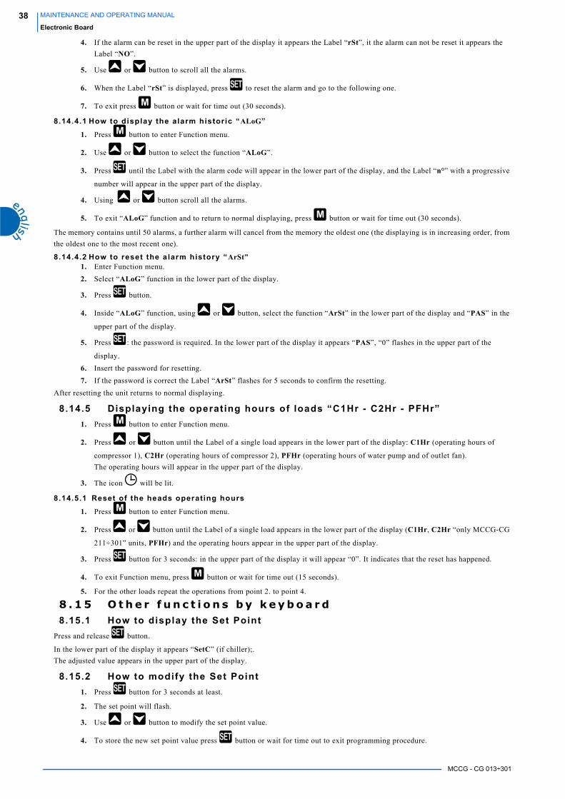
MCCG - CG 013÷301
38 MAINTENANCE AND OPERATING MANUAL
Electronic Board
4. If the alarm can be reset in the upper part of the display it appears the Label “rSt”, it the alarm can not be reset it appears the
Label “NO”.
5. Use or button to scroll all the alarms.
6. When the Label “rSt” is displayed, press to reset the alarm and go to the following one.
7. To exit press button or wait for time out (30 seconds).
8.14.4.1 How to display the alarm historic “ALoG”
1. Press button to enter Function menu.
2. Use or button to select the function “ALoG”.
3. Press until the Label with the alarm code will appear in the lower part of the display, and the Label “n°” with a progressive
number will appear in the upper part of the display.
4. Using or button scroll all the alarms.
5. To exit “ALoG” function and to return to normal displaying, press button or wait for time out (30 seconds).
The memory contains until 50 alarms, a further alarm will cancel from the memory the oldest one (the displaying is in increasing order, from
the oldest one to the most recent one).
8.14.4.2 How to reset the alarm history “ArSt”1. Enter Function menu.
2. Select “ALoG” function in the lower part of the display.
3. Press button.
4. Inside “ALoG” function, using or button, select the function “ArSt” in the lower part of the display and “PAS” in the
upper part of the display.
5. Press : the password is required. In the lower part of the display it appears “PAS”, “0” flashes in the upper part of the
display.
6. Insert the password for resetting.
7. If the password is correct the Label “ArSt” flashes for 5 seconds to confirm the resetting.
After resetting the unit returns to normal displaying.
8.14.5 Displaying the operat ing hours of loads “C1Hr - C2Hr - PFHr”1. Press button to enter Function menu.
2. Press or button until the Label of a single load appears in the lower part of the display: C1Hr (operating hours of
compressor 1), C2Hr (operating hours of compressor 2), PFHr (operating hours of water pump and of outlet fan).
The operating hours will appear in the upper part of the display.
3. The icon will be lit.
8.14.5.1 Reset of the heads operating hours
1. Press button to enter Function menu.
2. Press or button until the Label of a single load appears in the lower part of the display (C1Hr, C2Hr “only MCCG-CG
211÷301” units, PFHr) and the operating hours appear in the upper part of the display.
3. Press button for 3 seconds: in the upper part of the display it will appear “0”. It indicates that the reset has happened.
4. To exit Function menu, press button or wait for time out (15 seconds).
5. For the other loads repeat the operations from point 2. to point 4.
8 . 1 5 O t h e r f u n c t i o n s b y k e y b o a r d8.15.1 How to display the Set Point
Press and release button.
In the lower part of the display it appears “SetC” (if chiller);.
The adjusted value appears in the upper part of the display.
8.15.2 How to modify the Set Point1. Press button for 3 seconds at least.
2. The set point will flash.
3. Use or button to modify the set point value.
4. To store the new set point value press button or wait for time out to exit programming procedure.

MCCG - CG 013÷301
39MAINTENANCE AND OPERATING MANUAL
Electronic Board
8 . 1 6 A l a r m c o d e s a n d a c t i o n s
COD. MEANING CAUSE ACTION RESET
P1 Alarm of BEWIT
probe
Probe damaged or
resistive value out
of range
“open collector” outlet / alarm relay is
activated
The buzzer is activated
The icon for general alarm flashes
The alarm code is displayed
Automatic
If the resistive value returns within the
envisaged range.
P2 Alarm of BEWOT
probe
Probe damaged or
resistive value out
of range
“open collector” outlet / alarm relay is
activated
The buzzer is activated
The icon for general alarm flashes
The alarm code is displayed
Automatic
If the resistive value returns within the
envisaged range.
P3 Alarm of BCP1 probe
Probe damaged or
resistive value /
power value out of
range
“open collector” outlet / alarm relay is
activated
The buzzer is activated
The icon for general alarm flashes
The alarm code is displayed
Automatic
If the resistive value returns within the
envisaged range.
P4 Alarm of BAT1 probe
Probe damaged or
resistive value out
of range
“open collector” outlet / alarm relay is
activated
The buzzer is activated
The icon for general alarm flashes
The alarm code is displayed
Automatic
If the resistive value returns within the
envisaged range.
A01 High pressure
switch alarm
Digital input / high
pressure switch
enabled
“open collector” outlet / alarm relay is
activated
The buzzer is activated
The icon for high pressure alarm flashes
The alarm code is displayed
Manual
The digital input is disabled and the
resetting procedure is carried out
A02 Low pressure
switch alarm
Digital input / low
pressure switch
enabled
“open collector” outlet / alarm relay is
activated
The buzzer is activated
The icon for low pressure alarm flashes
The alarm code is displayed
Automatic
It becomes manual after the value set of
“tripping per hour”
Manual
The digital input is disabled and the
resetting procedure is carried out
A05 High temperature
High pressure
Analogue input
enabled if BCP1 or
BAT1 > of “set value”
“open collector” outlet / alarm relay is
activated
The buzzer is activated
The icon for general alarm flashes
The alarm code is displayed
manual
Disabled if BCP1 or BAT1 < “se vale”
and the resetting procedure is carried out
A06 Low pressure /
temperature alarm
Analogue input
enabled if BCP1 or
BAT1 < “set value”
“open collector” outlet / alarm relay is
activated
The buzzer is activated
The icon for general alarm flashes
The alarm code is displayed
Manual
Disabled if BCP1 or BAT1 > “set value”and the resetting procedure is
carried out
A07 Antifreeze alarm Digital input
enabled if BEWOT
< “set value” and
actives for the
“time set”
“open collector” outlet / alarm relay is
activated
The buzzer is activated
The icon for general alarm flashes
The alarm code is displayed
Automatic
It becomes manual after “tripping per hour”
Manual
Disabling:
- when the antifreeze regulation probe
BEWOT > (AR03+AR04) in chiller
modality;
and resetting procedure
Table 6 ALARM CODES AND ACTIONS

MCCG - CG 013÷301
40 MAINTENANCE AND OPERATING MANUAL
Electronic Board
A07 Antifreeze alarm Digital input
enabled if
“open collector” outlet / alarm relay is
activated
The buzzer is activated
The icon for general alarm flashes
The alarm code is displayed
Automatic
It becomes manual after “tripping per hour”
Manual
Disabling:
digital input not enabled
resetting procedure
A07 Antifreeze alarm
motocondensing
units
Digital input
enabled
“open collector” outlet / alarm relay is
activated
The buzzer is activated
The icon for general alarm flashes
The alarm code is displayed
Automatic
It becomes manual after “alarms interventions”
Manual
Disabling:
digital input disabled and the resetting
procedure is carried out
A08 Flow meter alarm
(air/water or
water/water units)
Digital input
enabled
enabled for “time set”
“open collector” outlet / alarm relay is
activated
The buzzer is activated
The icon for flow meter alarm flashes
The alarm code is displayed
Automatic
It becomes manual after “tripping per hour”
Manual
Disabling:
Digital input disabled for “time set” and
reset procedure
A09 Compressor 1
thermal alarm
Digital input
enabled
“open collector” outlet / alarm relay is
activated
The buzzer is activated
The icon for general alarm flashes
The alarm code is displayed
Manual
Digital input disabled and the resetting
procedure is carried out
A10 Compressor 2
thermal alarm
Digital input
enabled
“open collector” outlet / alarm relay are
activated
The buzzer is activated
The icon for general alarm flashes
The alarm code is displayed
Manual
Digital input disabled and the resetting
procedure is carried out
A09-A10
Compressor1-2
thermal alarm
The alarm is
visualized but not
enabled during
“compressor thermal delay time” after
compressor start up
Relay alarm + buzzer activated If ID is not activated
Manual
To reset the alarm enter the
programming
A11 Pump thermal
alarm
Digital input
enabled
“open collector” outlet / alarm relay is
activated
The buzzer is activated
The icon for general alarm flashes
The alarm code is displayed
Manual
Digital input disabled and the resetting
procedure is carried out
A13 Compressor 1
maintenance alarm
Operating hours >
“set treshold”
“open collector” outlet / alarm relay is
activated
The buzzer is activated
The icon for general alarm flashes
The alarm code is displayed
Manual
Operating hours reset
A14 Compressor 2
maintenance alarm
Operating hours >
“set treshold”
“open collector” outlet / alarm relay are
activated
The buzzer is activated
The alarm code is displayed
Manual
Operating hours reset
A15 Water pump /
outlet fan (air/air)
maintenance alarm
Operating hours>
“set treshold”
“open collector” outlet / alarm relay are
activated
The buzzer is activated
The alarm code is displayed
Manual
Operating hour reset
COD. MEANING CAUSE ACTION RESET
Table 6 ALARM CODES AND ACTIONS
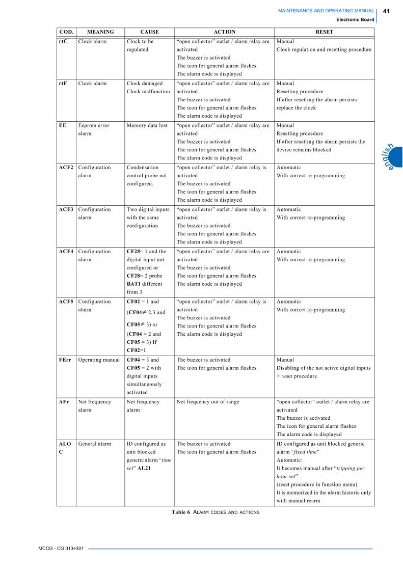
MCCG - CG 013÷301
41MAINTENANCE AND OPERATING MANUAL
Electronic Board
rtC Clock alarm Clock to be
regulated
“open collector” outlet / alarm relay are
activated
The buzzer is activated
The icon for general alarm flashes
The alarm code is displayed
Manual
Clock regulation and resetting procedure
rtF Clock alarm Clock damaged
Clock malfunction
“open collector” outlet / alarm relay are
activated
The buzzer is activated
The icon for general alarm flashes
The alarm code is displayed
Manual
Resetting procedure
If after resetting the alarm persists
replace the clock
EE Eeprom error
alarm
Memory data lost “open collector” outlet / alarm relay are
activated
The buzzer is activated
The icon for general alarm flashes
The alarm code is displayed
Manual
Resetting procedure
If after resetting the alarm persists the
device remains blocked
ACF2 Configuration
alarm
Condensation
control probe not
configured.
“open collector” outlet / alarm relay is
activated
The buzzer is activated
The icon for general alarm flashes
The alarm code is displayed
Automatic
With correct re-programming
ACF3 Configuration
alarm
Two digital inputs
with the same
configuration
“open collector” outlet / alarm relay is
activated
The buzzer is activated
The icon for general alarm flashes
The alarm code is displayed
Automatic
With correct re-programming
ACF4 Configuration
alarm
CF28= 1 and the
digital input not
configured or
CF28= 2 probe
BAT1 different
from 3
“open collector” outlet / alarm relay are
activated
The buzzer is activated
The icon for general alarm flashes
The alarm code is displayed
Automatic
With correct re-programming
ACF5 Configuration
alarm
CF02 = 1 and
(CF04 2,3 and
CF05 3) or
(CF04 = 2 and
CF05 = 3) If
CF02=1
“open collector” outlet / alarm relay is
activated
The buzzer is activated
The icon for general alarm flashes
The alarm code is displayed
Automatic
With correct re-programming
FErr Operating manual CF04 = 3 and
CF05 = 2 with
digital inputs
simultaneously
activated
The buzzer is activated
The icon for general alarm flashes
Manual
Disabling of the not active digital inputs
+ reset procedure
AFr Net frequency
alarm
Net frequency
alarm
Net frequency out of range “open collector” outlet / alarm relay are
activated
The buzzer is activated
The icon for general alarm flashes
The alarm code is displayed
ALOC
General alarm ID configured as
unit blocked
generic alarm “time set” AL21
The buzzer is activated
The icon for general alarm flashes
ID configured as unit blocked generic
alarm “fixed time”
Automatic:
It becomes manual after “tripping per hour set”
(reset procedure in function menu).
It is memorized in the alarm historic only
with manual rearm
COD. MEANING CAUSE ACTION RESET
Table 6 ALARM CODES AND ACTIONS
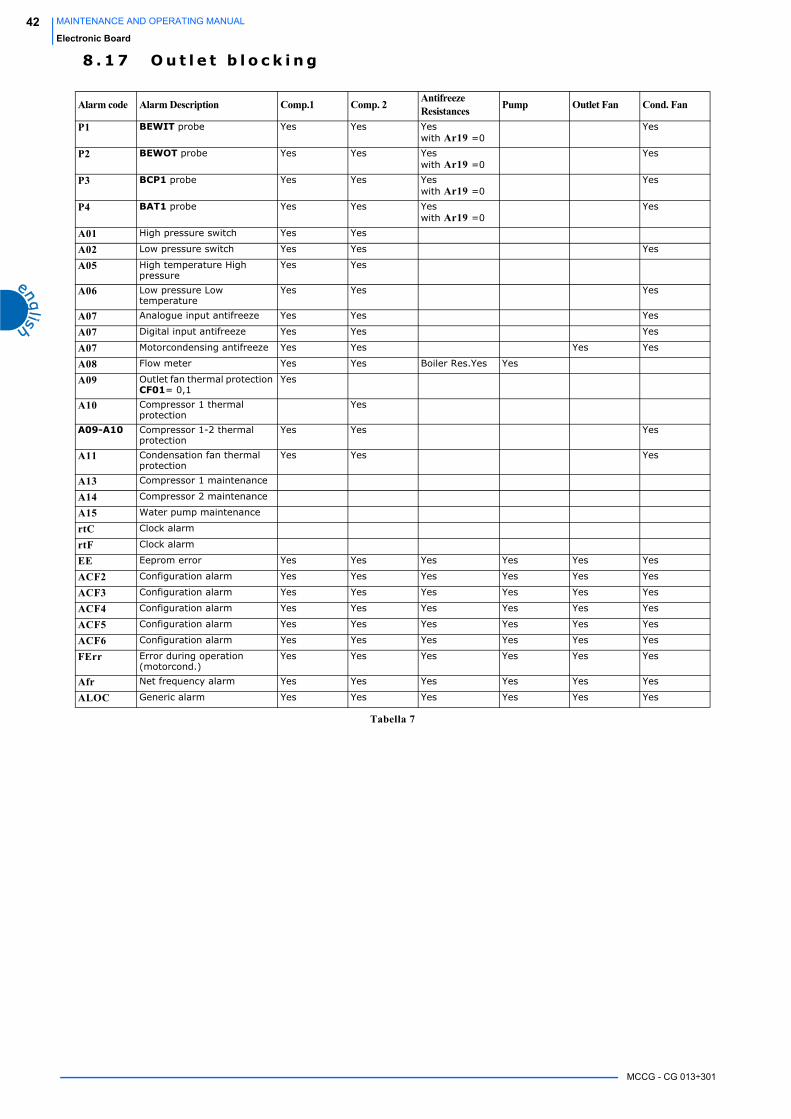
MCCG - CG 013÷301
42 MAINTENANCE AND OPERATING MANUAL
Electronic Board
8 . 1 7 O u t l e t b l o c k i n g
Alarm code Alarm Description Comp.1 Comp. 2 Antifreeze Resistances Pump Outlet Fan Cond. Fan
P1 BEWIT probe Yes Yes Yeswith Ar19 =0
Yes
P2 BEWOT probe Yes Yes Yeswith Ar19 =0
Yes
P3 BCP1 probe Yes Yes Yeswith Ar19 =0
Yes
P4 BAT1 probe Yes Yes Yeswith Ar19 =0
Yes
A01 High pressure switch Yes Yes
A02 Low pressure switch Yes Yes Yes
A05 High temperature High pressure
Yes Yes
A06 Low pressure Low temperature
Yes Yes Yes
A07 Analogue input antifreeze Yes Yes Yes
A07 Digital input antifreeze Yes Yes Yes
A07 Motorcondensing antifreeze Yes Yes Yes Yes
A08 Flow meter Yes Yes Boiler Res.Yes Yes
A09 Outlet fan thermal protection CF01= 0,1
Yes
A10 Compressor 1 thermal protection
Yes
A09-A10 Compressor 1-2 thermal protection
Yes Yes Yes
A11 Condensation fan thermal protection
Yes Yes Yes
A13 Compressor 1 maintenance
A14 Compressor 2 maintenance
A15 Water pump maintenance
rtC Clock alarm
rtF Clock alarm
EE Eeprom error Yes Yes Yes Yes Yes Yes
ACF2 Configuration alarm Yes Yes Yes Yes Yes Yes
ACF3 Configuration alarm Yes Yes Yes Yes Yes Yes
ACF4 Configuration alarm Yes Yes Yes Yes Yes Yes
ACF5 Configuration alarm Yes Yes Yes Yes Yes Yes
ACF6 Configuration alarm Yes Yes Yes Yes Yes Yes
FErr Error during operation (motorcond.)
Yes Yes Yes Yes Yes Yes
Afr Net frequency alarm Yes Yes Yes Yes Yes Yes
ALOC Generic alarm Yes Yes Yes Yes Yes Yes
Tabella 7

MCCG - CG 013÷301
43MAINTENANCE AND OPERATING MANUAL
Electronic Board
8 . 1 8 P a r a m e t e r s d e s c r i p t i o n8.18.1 Thermoregulation parameters
8.18.2 Configurat ion parameters
Parameters Description
ST01 It allows to fix the operating set point during chiller operation (from ST05 to ST06)
ST02 It allows to fix the differential during chiller operation
ST03 It allows to fix the operating set point during heat pump operation (from ST07 to ST08)
ST04 It allows to fix the differential during heat pump operation
Pr2 Password: it allows to set the numeric code of the password (from 0 to 999)
Table 8 THERMOREGULATION PARAMETERS DESCRIPTION
Parameters Description
CF02 Motorcondensing unit:
• 0= Yes
• 1= Not
CF04 Configuration of analogue input BEWIT• 0 = Probe absent
• 1= NTC temperature probe evaporator water inlet (ambient air to be conditioned). It appears in the upper
part of the display.
• 2 = Digital input (for units configured as motorcondensing).
According to the selected polarity, with energized contact, it puts the unit in stand-by and starts it. ON is
displayed in the upper part. With de-energized contact the unit is in stand-by, OFF is displayed in the
upper part. If ON appears in the upper part of the display, using UP-DOWN buttons it is possible to select
the operating modality (chiller - heat pump). During chiller modality: with CF21=2 and CO08=1
compressor 1 starts, with CF21=2 and CO08=0 a compressor required by the thermoregulator starts.
“OnC” is displayed in the upper part.
During heat pump modality: with CF21=2 and CO08= 1 compressor 1 starts, with CF21=2 and CO08= 0a
compressor required by the thermoregulator starts. “OnH” is displayed in the upper part.
When the modality has been chosen, the digital input enabling or disabling will switch on or off the unit
and the appropriate loads (compressor). Only when the contact is energized, if the unit was switched off
by keyboard, it must be switched on again by keyboard.
• 3 = Digital input (for units configured as motorcondensing), according to the selected polarity it gives the
possibility to switch on the unit in chiller modality ONLY.
With de-energized contact, unit in stand-by, OFF displayed in the upper part.
With energized contact, unit in chiller operation. “OnC” displayed in the upper part.
The digital input enabling or disabling will switch on or off the unit and the appropriate loads
(compressor).
Only when the contact is energized, if the unit was switched off by keyboard, it must be switched on again
by keyboard.
CF05 Configuration of analogue input BEWOT• 0=Probe absent
• 1=NTC temperature probe evaporator water outlet / evaporator air outlet.
It appears in the upper part of the display.
• 2=It becomes a digital input which, according to the selected polarity, generates the antifreeze alarm.
• 3=Digital input (for unit configured as motorcondensing).
According to the selected polarity it gives the possibility to switch on the unit in heat pump modality
ONLY.
With de-energized contact, unit in stand-by, OFF displayed in the upper part.
With energized contact, unit in chiller operation.
“OnH” displayed in the upper part.
The digital input enabling or disabling will switch on or off the unit and the appropriate loads
(compressor).
Only when the contact is energized, if the unit was switched off by keyboard, it must be switched on again
by keyboard.
Table 9 CONFIGURATION PARAMETERS DESCRIPTION
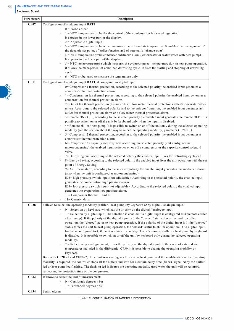
MCCG - CG 013÷301
44 MAINTENANCE AND OPERATING MANUAL
Electronic Board
CF07 Configuration of analogue input BAT1• 0 = Probe absent
• 1 = NTC temperature probe for the control of the condensation fan speed regulation.
It appears in the lower part of the display.
• 2 = Adjustable digital input
• 3 = NTC temperature probe which measures the external air temperature. It enables the management of
the dynamic set point, of boiler function and of automatic “change-over”.
• 4 = NTC temperature probe condenser antifreeze alarm (water/water or water/water with heat pump).
It appears in the lower part of the display.
• 5 = NTC temperature probe which measures the evaporating coil temperature during heat pump operation,
it allows the management of combined defrosting cycle. It fixes the starting and stopping of defrosting
cycle.
• 6 = NTC probe, used to measure the temperature only
CF11 Configuration of analogue input BATI, if configured as digital input
• 0= Compressor 1 thermal protection, according to the selected polarity the enabled input generates a
compressor thermal protection alarm.
• 1= Condensation fan thermal protection, according to the selected polarity the enabled input generates a
condensation fan thermal protection alarm.
• 2= Outlet fan thermal protection (air/air units) / Flow meter thermal protection (water/air or water/water
units). According to the selected polarity and to the unit configuration, the enabled input generates an
outlet fan thermal protection alarm or a flow meter thermal protection alarm.
• 3= remote ON / OFF, according to the selected polarity the enabled input generates the remote OFF. It is
possible to switch on or off the unit by keyboard only when the input is disabled.
• 4= Remote chiller / heat pump. It is possible to switch on or off the unit only during the selected operating
modality (see the section about the way to select the operating modality, parameter CF28 = 1).
• 5= Compressor 2 thermal protection, according to the selected polarity the enabled input generates a
compressor thermal protection alarm
• 6= Compressor 2 / capacity step required, according the selected polarity (unit configured as
motorcondensing) the enabled input switches on or off a compressor or the capacity control solenoid
valve.
• 7= Defrosting end, according to the selected polarity the enabled input fixes the defrosting cycle end.
• 8= Energy Saving, according to the selected polarity the enabled input fixes the unit operation with the set
point of Energy Saving.
• 9= Antifreeze alarm, according to the selected polarity the enabled input generates the antifreeze alarm
(also when the unit is configured as motorcondensing).
ID3= high pressure switch input (not adjustable). According to the selected polarity the enabled input
generates the condensation high pressure alarm.
ID4= low pressure switch input (not adjustable). According to the selected polarity the enabled input
generates the evaporation low pressure alarm.
• 10= Compressor thermal 1 and 2.
• 11= Generic alarm
CF28 t allows to select the operating modality (chiller / heat pump) by keyboard or by digital / analogue input.
• 0 = Selection by keyboard which has the priority on the digital / analogue input.
• 1 = Selection by digital input. The selection is enabled if a digital input is configured as 4 (remote chiller
/ heat pump). If the polarity of the digital input is 0: the “opened” status forces the unit to chiller
operation, the “closed” status to heat pump operation. If the polarity of the digital input is 1: the “opened”
status forces the unit to heat pump operation, the “closed” status to chiller operation. If no digital input
has been configured to 4, the unit remains in stand-by. The selection to chiller or heat pump by keyboard
is disabled. It is possible to switch on or off the unit by keyboard only during the selected operating
modality.
• 2 = Selection by analogue input, it has the priority on the digital input. In the event of external air
temperatures included in the differential CF30, it is possible to change the operating modality by
keyboard.
Both with CF28 =1 and CF28=2, if the unit is operating as chiller or as heat pump and the modification of the operating
modality is required, the controller stops all the outlets and wait for a certain delay time (fixed), signalled by the chiller
led or heat pump led flashing. The flashing led indicates the operating modality used when the unit will be restarted,
respecting the protection time of the compressor.
CF32 It allows to select the unit of measurement:
• 0 = Centigrade degrees / bar
• 1 = Fahrenheit degrees / psi
CF34 Serial address
Parameters Description
Table 9 CONFIGURATION PARAMETERS DESCRIPTION

MCCG - CG 013÷301
45MAINTENANCE AND OPERATING MANUAL
Electronic Board
8.18.3 Dynamic set point parameters (NOT ENABLED FUNCTION)
8.18.4 Energy Saving parameters (NOT ENABLED FUNCTION)
8.18.5 Compressor parameters
8.18.6 Venti lat ion parameters
8.18.7 Antifreeze support boiler resistance parameters
8.18.8 Defrosting parameters
CF36 It allows to select the default displaying of the upper and lower part.
• 0 = BEWIT temperature is displayed in the upper part, BCP1 or BAT1 is displayed in the lower part.
• 1 = BEWOT temperature is displayed in the upper part, BCP1 or BAT1 is displayed in the lower part.
• 2 =BEWOT temperature is displayed in the upper pert of the display, the lower part visualize SET LASER
(NOT ENABLED FUNCTION).
• 3 = BEWIT temperature is displayed in the upper part, BEWOT is displayed in the lower part.
Pr2 Password: it allows to fix a numeric code for the password (from 0 to 999)
Parameters Description
Pr2 Password: it allows to fix a numeric code for the password (from 0 to 999)
Table 10 DYNAMIC SET POINT PARAMETERS
Parameters Description
Pr2 Password: it allows to fix a numeric code for the password (from 0 to 999)
Table 11 ENERGY SAVING PARAMETERS DESCRIPTION
Parameters Description
Pr2 Password: it allows to fix a numeric code for the password (from 0 to 999)
Table 12 COMPRESSORS PARAMETERS DESCRIPTION
Parameters Description
Pr2 Password: it allows to fix a numeric code for the password (from 0 to 999)
Table 13 VENTILATION PARAMETERS DESCRIPTION
Parameters Description
Pr2 Password: it allows to fix a numeric code for the password (from 0 to 999)
Table 14 ANTIFREEZE SUPPORT BOILER RESISTANCE PARAMETERS
Parameters Description
Pr2 Password: it allows to fix a numeric code for the password (from 0 to 999)
Table 15 DEFROSTING PARAMETERS DESCRIPTION
Parameters Description
Table 9 CONFIGURATION PARAMETERS DESCRIPTION
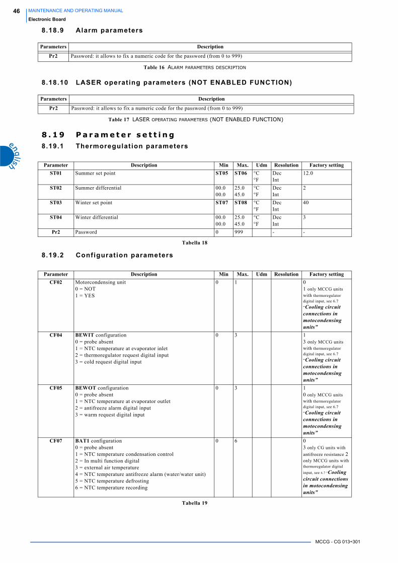
MCCG - CG 013÷301
46 MAINTENANCE AND OPERATING MANUAL
Electronic Board
8.18.9 Alarm parameters
8.18.10 LASER operating parameters (NOT ENABLED FUNCTION)
8 . 1 9 P a r a m e t e r s e t t i n g8.19.1 Thermoregulat ion parameters
8.19.2 Configuration parameters
Parameters Description
Pr2 Password: it allows to fix a numeric code for the password (from 0 to 999)
Table 16 ALARM PARAMETERS DESCRIPTION
Parameters Description
Pr2 Password: it allows to fix a numeric code for the password (from 0 to 999)
Table 17 LASER OPERATING PARAMETERS (NOT ENABLED FUNCTION)
Parameter Description Min Max. Udm Resolution Factory settingST01 Summer set point ST05 ST06 °C
°FDecInt
12.0
ST02 Summer differential 00.000.0
25.045.0
°C°F
DecInt
2
ST03 Winter set point ST07 ST08 °C°F
DecInt
40
ST04 Winter differential 00.000.0
25.045.0
°C°F
DecInt
3
Pr2 Password 0 999 - -
Tabella 18
Parameter Description Min Max. Udm Resolution Factory settingCF02 Motorcondensing unit
0 = NOT1 = YES
0 1 01 only MCCG units with thermoregulator
digital input, see 6.7
“Cooling circuit connections in motocondensing units”
CF04 BEWIT configuration0 = probe absent1 = NTC temperature at evaporator inlet2 = thermoregulator request digital input3 = cold request digital input
0 3 13 only MCCG units with thermoregulator
digital input, see 6.7
“Cooling circuit connections in motocondensing units”
CF05 BEWOT configuration0 = probe absent1 = NTC temperature at evaporator outlet2 = antifreeze alarm digital input3 = warm request digital input
0 3 10 only MCCG units with thermoregulator
digital input, see 6.7
“Cooling circuit connections in motocondensing units”
CF07 BAT1 configuration0 = probe absent1 = NTC temperature condensation control2 = In multi function digital3 = external air temperature4 = NTC temperature antifreeze alarm (water/water unit)5 = NTC temperature defrosting6 = NTC temperature recording
0 6 03 only CG units with
antifreeze resistance 2 only MCCG units with thermoregulator digital
input, see 6.7 “Cooling circuit connections in motocondensing units”
Tabella 19
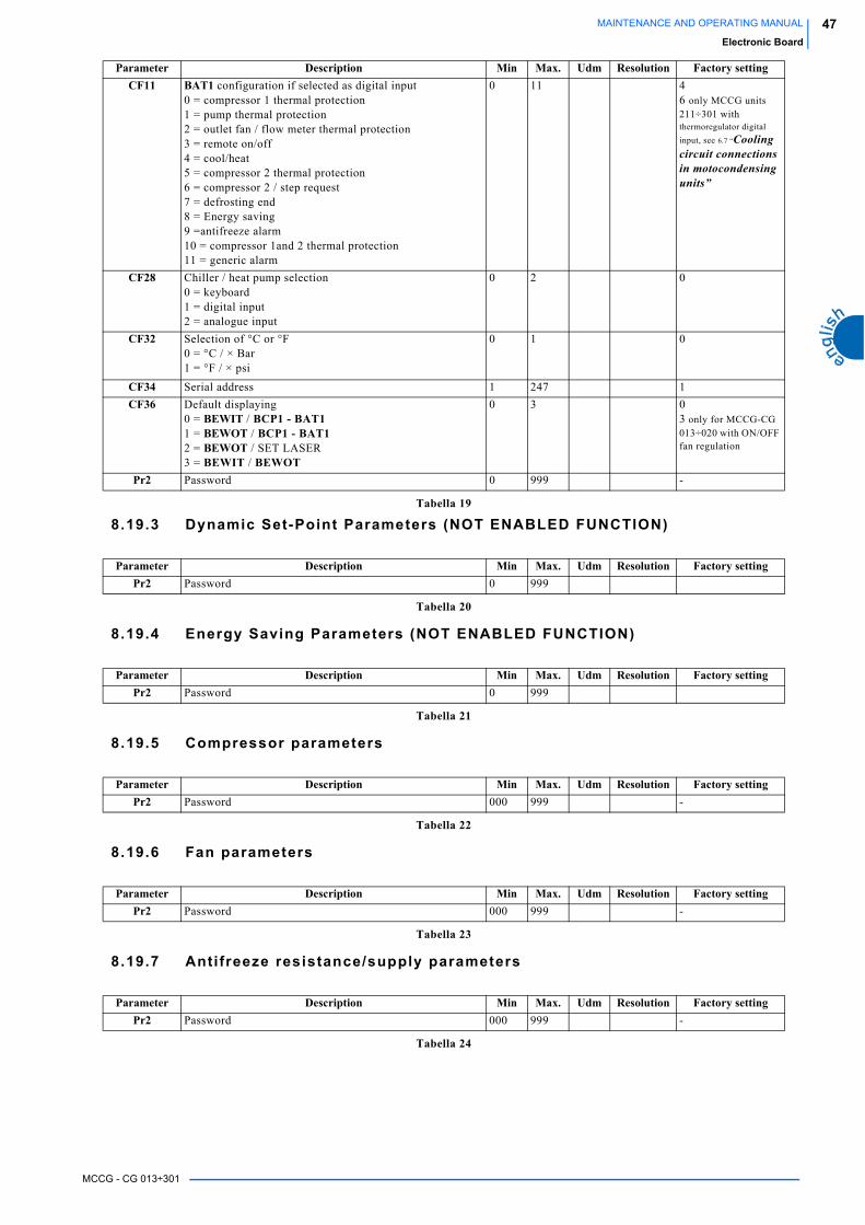
MCCG - CG 013÷301
47MAINTENANCE AND OPERATING MANUAL
Electronic Board
8.19.3 Dynamic Set-Point Parameters (NOT ENABLED FUNCTION)
8.19.4 Energy Saving Parameters (NOT ENABLED FUNCTION)
8.19.5 Compressor parameters
8.19.6 Fan parameters
8.19.7 Antifreeze resistance/supply parameters
CF11 BAT1 configuration if selected as digital input0 = compressor 1 thermal protection1 = pump thermal protection2 = outlet fan / flow meter thermal protection3 = remote on/off4 = cool/heat5 = compressor 2 thermal protection6 = compressor 2 / step request7 = defrosting end8 = Energy saving9 =antifreeze alarm10 = compressor 1and 2 thermal protection11 = generic alarm
0 11 4 6 only MCCG units 211÷301 with thermoregulator digital
input, see 6.7 “Cooling circuit connections in motocondensing units”
CF28 Chiller / heat pump selection0 = keyboard1 = digital input2 = analogue input
0 2 0
CF32 Selection of °C or °F0 = °C / × Bar1 = °F / × psi
0 1 0
CF34 Serial address 1 247 1
CF36 Default displaying 0 = BEWIT / BCP1 - BAT11 = BEWOT / BCP1 - BAT12 = BEWOT / SET LASER3 = BEWIT / BEWOT
0 3 03 only for MCCG-CG 013÷020 with ON/OFF fan regulation
Pr2 Password 0 999 -
Parameter Description Min Max. Udm Resolution Factory settingPr2 Password 0 999
Tabella 20
Parameter Description Min Max. Udm Resolution Factory settingPr2 Password 0 999
Tabella 21
Parameter Description Min Max. Udm Resolution Factory settingPr2 Password 000 999 -
Tabella 22
Parameter Description Min Max. Udm Resolution Factory settingPr2 Password 000 999 -
Tabella 23
Parameter Description Min Max. Udm Resolution Factory settingPr2 Password 000 999 -
Tabella 24
Parameter Description Min Max. Udm Resolution Factory setting
Tabella 19

MCCG - CG 013÷301
48 MAINTENANCE AND OPERATING MANUAL
Electronic Board
8.19.8 Defrosting parameters
8.19.9 Alarm parameters
8.19.10 LASER parameters (NOT ENABLED FUNCTION)
8 . 2 0 P r o b e d e s c r i p t i o nFor the positioning of the BEWIT, BEWOT, BCP1 and BAT1 probes, see annexes.
Here below you can find the descriptions of the probes:
Parameter Description Min Max. Udm Resolution Factory settingPr2 Password 0 999
Tabella 25
Parameter Description Min Max. Udm Resolution Factory settingPr2 Password 0 999
Tabella 26
Parameter Description Min Max. Udm Resolution Factory settingPr2 Password 0 999
Tabella 27
Code Connector name DESCRIPTIONBEWIT PB1 EVAPORATOR WATER INLET TEMPERATURE PROBE
BEWOT PB2 EVAPORATOR WATER OUTLET TEMPERATURE PROBE
BCP1 PB3 CONDENSER OUTLET PRESSURE TRANSDUCER
BAT1 PB4 AMBIENT TEMPERATURE PROBE IN CG UNITSCONDENSING COIL AMBIENT TEMPERATURE PROBE IN MCCG UNITS (motorcondensing)

MCCG - CG 013÷301
49MAINTENANCE AND OPERATING MANUAL
Other components setting
CHAPTER 9
OTHER COMPONENTS SETTING9 . 1 R e f r i g e r a n t h i g h a n d l o w p r e s s u r e s w i t c h e s
The units are fitted with the following pressure switches:
1. low pressure switch (LP)This monitors refrigerant compressor intake pressure and will trip to avoid that values dangerous for compressor normal
operation are reached.
It is of an “automatic reset” type.
The alarm A02 (see chapter 8.16 “Alarm codes and actions”),produced by this pressure switch tripping, an have a delay time
after the compressor starting to avoid simple intake pressure fluctuations or false alarms interfere with the unit normal
operation.
After the time set, the pressure switch tripping will be detected by the electronic board which will display the alarm signal A02 (see chapter 8.16 “Alarm codes and actions”) band will stop the compressor/s and fan/s while the pump (if it is installed) will
continue to operate.
After the alarm tripping, if the compressor intake pressure increases and exceeds the pressure switch tripping value it will
restart.
It will be possible to start up the unit again following the alarm reset procedure described in chapter Chapter 8 “Electronic Board”.
If the cause of the pressure switch tripping has not removed this cycle will repeat continuously.
2. high pressure switch (HP)This monitors the refrigerant compressor discharge pressure and prevents it increases to levels dangerous for compressor
working and for people safety.
It is of an “automatic reset” type”.
Its tripping is detected by the electronic board which will open the compressor power supply circuit and will display the alarm
signal A01 (see chapter 8.16 “Alarm codes and actions”) and the fan/s will be activated for 60 seconds to the max. speed to
contrast the alarm situation, than they will be stopped.
When the compressor outlet pressure drops below the reset point it is reset.
It will be possible to start up the unit again following the alarm reset procedure described in chapter Chapter 8 “Electronic Board”.
If the cause of the pressure switch tripping has not removed this cycle will repeat continuously.
The pressure switches LP and HP are screwed to the refrigerant circuit piping with SCHRAEDER valves (with needle) which prevent
leakage during replacement.
The TRIP and RESET values of the pressure switches depend upon the refrigerant gas used and are listed in the table below:
COMPONENTS REFRIGERANT TRIP RESETbar °C °F bar °C °F
Low pressure switch LPR407c
1.7 -17.3 0.9 2.7 -8.9 16
High pressure switch HP 27.2 63.4 146.1 20.5 51.5 124.7
Table 28 SETTINGS OF THE HIGH AND LOW PRESSURE SWITCHES
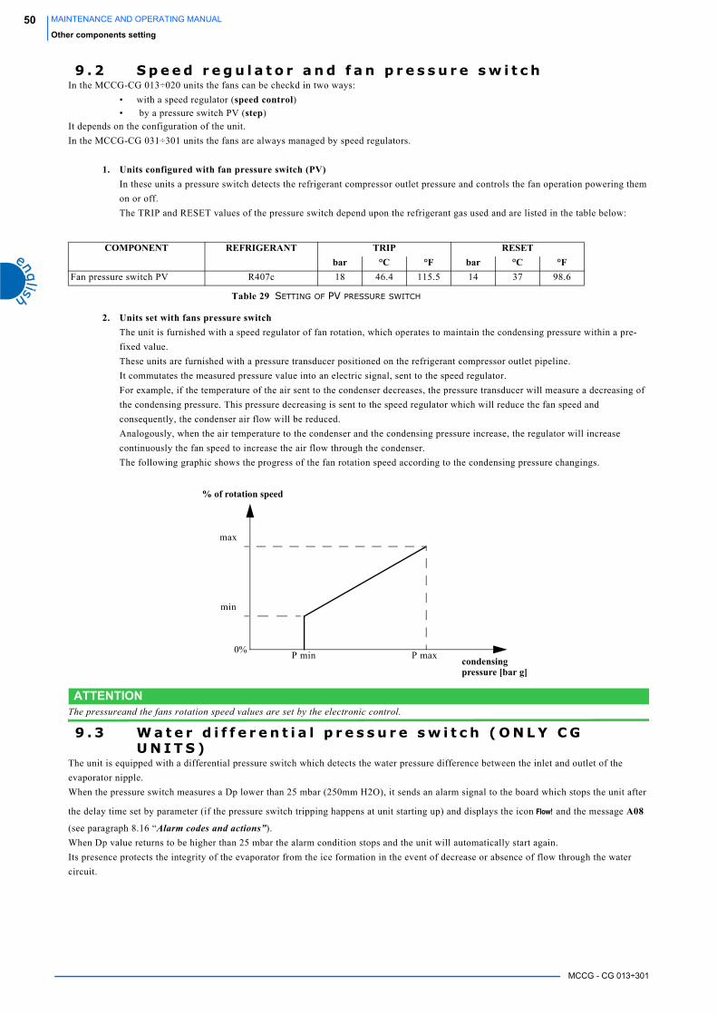
MCCG - CG 013÷301
50 MAINTENANCE AND OPERATING MANUAL
Other components setting
9 . 2 S p e e d r e g u l a t o r a n d f a n p r e s s u r e s w i t c hIn the MCCG-CG 013÷020 units the fans can be checkd in two ways:
• with a speed regulator (speed control)• by a pressure switch PV (step)
It depends on the configuration of the unit.
In the MCCG-CG 031÷301 units the fans are always managed by speed regulators.
1. Units configured with fan pressure switch (PV)In these units a pressure switch detects the refrigerant compressor outlet pressure and controls the fan operation powering them
on or off.
The TRIP and RESET values of the pressure switch depend upon the refrigerant gas used and are listed in the table below:
2. Units set with fans pressure switchThe unit is furnished with a speed regulator of fan rotation, which operates to maintain the condensing pressure within a pre-
fixed value.
These units are furnished with a pressure transducer positioned on the refrigerant compressor outlet pipeline.
It commutates the measured pressure value into an electric signal, sent to the speed regulator.
For example, if the temperature of the air sent to the condenser decreases, the pressure transducer will measure a decreasing of
the condensing pressure. This pressure decreasing is sent to the speed regulator which will reduce the fan speed and
consequently, the condenser air flow will be reduced.
Analogously, when the air temperature to the condenser and the condensing pressure increase, the regulator will increase
continuously the fan speed to increase the air flow through the condenser.
The following graphic shows the progress of the fan rotation speed according to the condensing pressure changings.
ATTENTIONThe pressureand the fans rotation speed values are set by the electronic control.
9 . 3 W a t e r d i f f e r e n t i a l p r e s s u r e s w i t c h ( O N L Y C G U N I T S )
The unit is equipped with a differential pressure switch which detects the water pressure difference between the inlet and outlet of the
evaporator nipple.
When the pressure switch measures a Dp lower than 25 mbar (250mm H2O), it sends an alarm signal to the board which stops the unit after
the delay time set by parameter (if the pressure switch tripping happens at unit starting up) and displays the icon and the message A08
(see paragraph 8.16 “Alarm codes and actions”).
When Dp value returns to be higher than 25 mbar the alarm condition stops and the unit will automatically start again.
Its presence protects the integrity of the evaporator from the ice formation in the event of decrease or absence of flow through the water
circuit.
COMPONENT REFRIGERANT TRIP RESETbar °C °F bar °C °F
Fan pressure switch PV R407c 18 46.4 115.5 14 37 98.6
Table 29 SETTING OF PV PRESSURE SWITCH
% of rotation speed
condensing pressure [bar g]
0%
max
min
P min P max
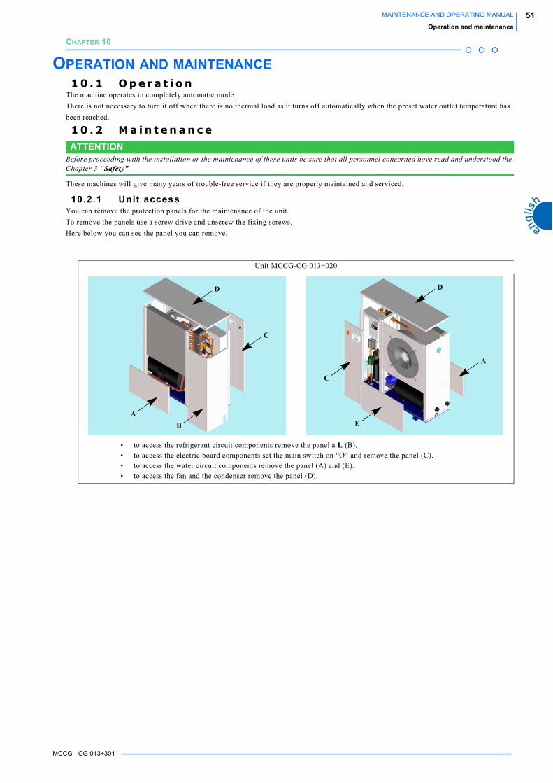
MCCG - CG 013÷301
51MAINTENANCE AND OPERATING MANUAL
Operation and maintenance
CHAPTER 10
OPERATION AND MAINTENANCE1 0 . 1 O p e r a t i o n
The machine operates in completely automatic mode.
There is not necessary to turn it off when there is no thermal load as it turns off automatically when the preset water outlet temperature has
been reached.
1 0 . 2 M a i n t e n a n c e
ATTENTIONBefore proceeding with the installation or the maintenance of these units be sure that all personnel concerned have read and understood the Chapter 3 “Safety”.
These machines will give many years of trouble-free service if they are properly maintained and serviced.
10.2.1 Unit accessYou can remove the protection panels for the maintenance of the unit.
To remove the panels use a screw drive and unscrew the fixing screws.
Here below you can see the panel you can remove.
Unit MCCG-CG 013÷020
• to access the refrigerant circuit components remove the panel a L (B).
• to access the electric board components set the main switch on “O” and remove the panel (C).
• to access the water circuit components remove the panel (A) and (E).
• to access the fan and the condenser remove the panel (D).
D
C
BA
D
E
C
A
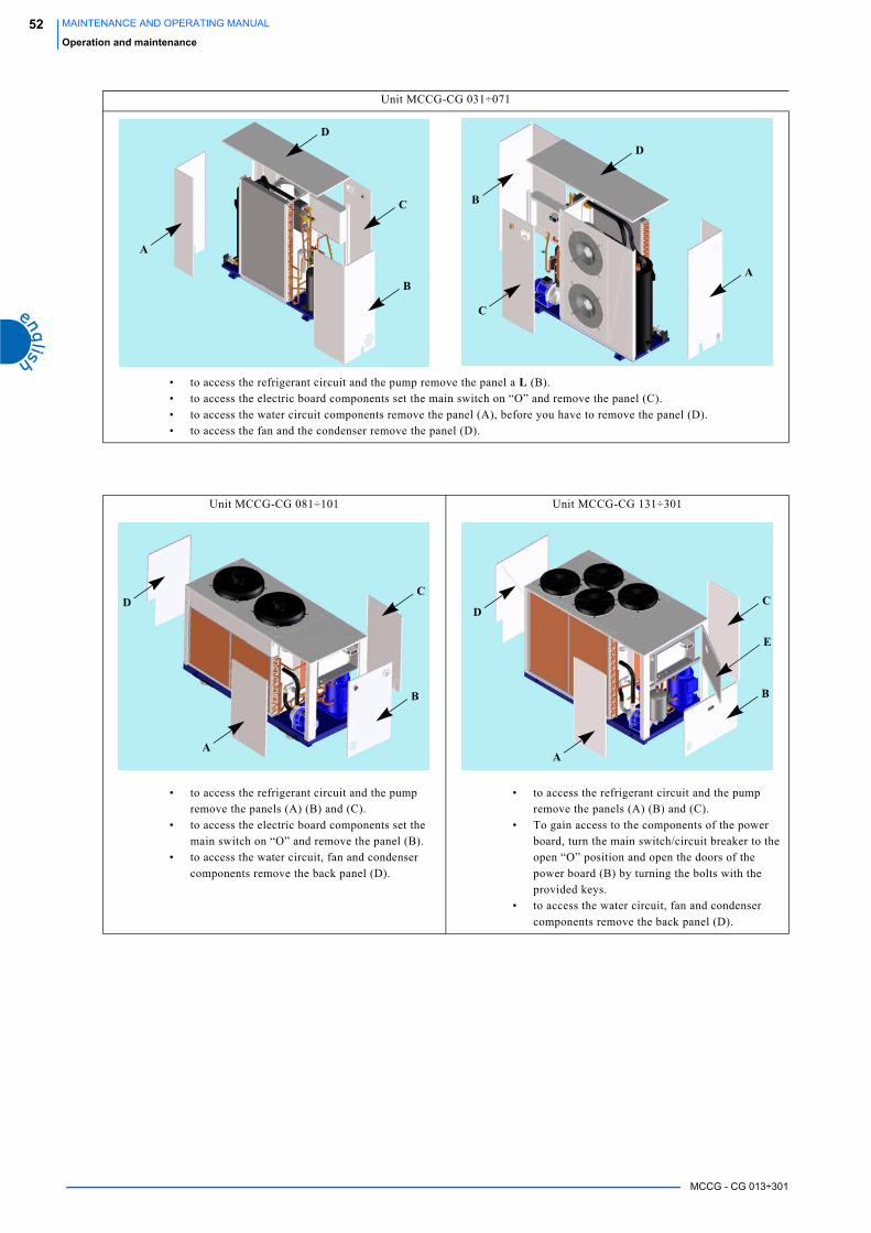
MCCG - CG 013÷301
52 MAINTENANCE AND OPERATING MANUAL
Operation and maintenance
Unit MCCG-CG 031÷071
• to access the refrigerant circuit and the pump remove the panel a L (B).
• to access the electric board components set the main switch on “O” and remove the panel (C).
• to access the water circuit components remove the panel (A), before you have to remove the panel (D).
• to access the fan and the condenser remove the panel (D).
Unit MCCG-CG 081÷101 Unit MCCG-CG 131÷301
• to access the refrigerant circuit and the pump
remove the panels (A) (B) and (C).
• to access the electric board components set the
main switch on “O” and remove the panel (B).
• to access the water circuit, fan and condenser
components remove the back panel (D).
• to access the refrigerant circuit and the pump
remove the panels (A) (B) and (C).
• To gain access to the components of the power
board, turn the main switch/circuit breaker to the
open “O” position and open the doors of the
power board (B) by turning the bolts with the
provided keys.
• to access the water circuit, fan and condenser
components remove the back panel (D).
D
C
B
A
A
C
B
D
CD
B
A
CD
B
A
E
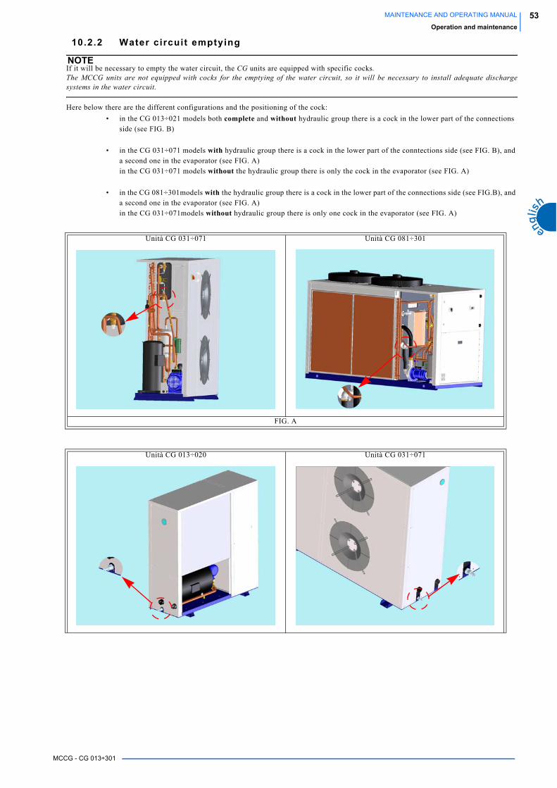
MCCG - CG 013÷301
53MAINTENANCE AND OPERATING MANUAL
Operation and maintenance
10.2.2 Water circuit emptying
NOTEIf it will be necessary to empty the water circuit, the CG units are equipped with specific cocks.The MCCG units are not equipped with cocks for the emptying of the water circuit, so it will be necessary to install adequate dischargesystems in the water circuit.
Here below there are the different configurations and the positioning of the cock:
• in the CG 013÷021 models both complete and without hydraulic group there is a cock in the lower part of the connections
side (see FIG. B)
• in the CG 031÷071 models with hydraulic group there is a cock in the lower part of the conntections side (see FIG. B), and
a second one in the evaporator (see FIG. A)
in the CG 031÷071 models without the hydraulic group there is only the cock in the evaporator (see FIG. A)
• in the CG 081÷301models with the hydraulic group there is a cock in the lower part of the connections side (see FIG.B), and
a second one in the evaporator (see FIG. A)
in the CG 031÷071models without hydraulic group there is only one cock in the evaporator (see FIG. A)
Unità CG 031÷071 Unità CG 081÷301
FIG. A
Unità CG 013÷020 Unità CG 031÷071

MCCG - CG 013÷301
54 MAINTENANCE AND OPERATING MANUAL
Operation and maintenance
ATTENTIONThe water circuit emptying operation becomes indispensable when the unit is without antifreeze resistance and must remain OFF for a long time in an ambient with temperatures which could reach the freezing values of water inside the evaporator (risk of evaporator breaking)
1 0 . 3 M a i n t e n a n c e s c h e d u l e
ATTENTION- This plan is based on an average working situation.- In some installations it may be necessary to increase the frequency of maintenance.
Unità CG 081÷301
FIG. B
OPERATION
1 da
y
1 m
onth
6 m
onth
s
1 ye
ar
Check for any alarm signals. xCheck that the water outlet temperature is within the envisaged range. xCheck that the water inlet temperature is in accordance with the value used for selecting the unit. xIn units with hydraulic group check that the pressure in the tank (with pump stopped) is about 0.5 bar. x
In units with hydraulic group check that the difference between the pump outlet pressure and inlet pressure (measured by a pressure gauge with the pump stopped) is within the limits envisaged and, in particular, is not lower than the value corresponding to the maximum flow.
x
Clean the water filter (if installed).We recommend to clean the filter after a week from the unit starting. x
Check that the liquid indicator (if present) is full or with a small stream of bubbles when the compressor is running. x
Check that the unit current absorption is within the values on the data plate. xCarry out visual inspection of refrigerant circuit, looking out for any deterioration of the piping or any traces of oil which might indicate a refrigerant leak. x
Check the condition and security of piping connections. xCheck the condition and security of electrical connections. xUsing a spanner, check that the connections between the compressor inlet and outlet pipelines have not slackened. x
Check that the ambient air temperature is in accordance to the value used for selecting the machine (normally 30-35°C / 77-86°F).Check that the ambient is well ventilated.
x
Check that the fan operation is automatically started up.Clean the condenser fins with a soft sponge or a jet of clean compressed air.Check that the grilles of the unit are free from dirt and any other obstructions.
x
Clean condenser fins with a mild detergent. x
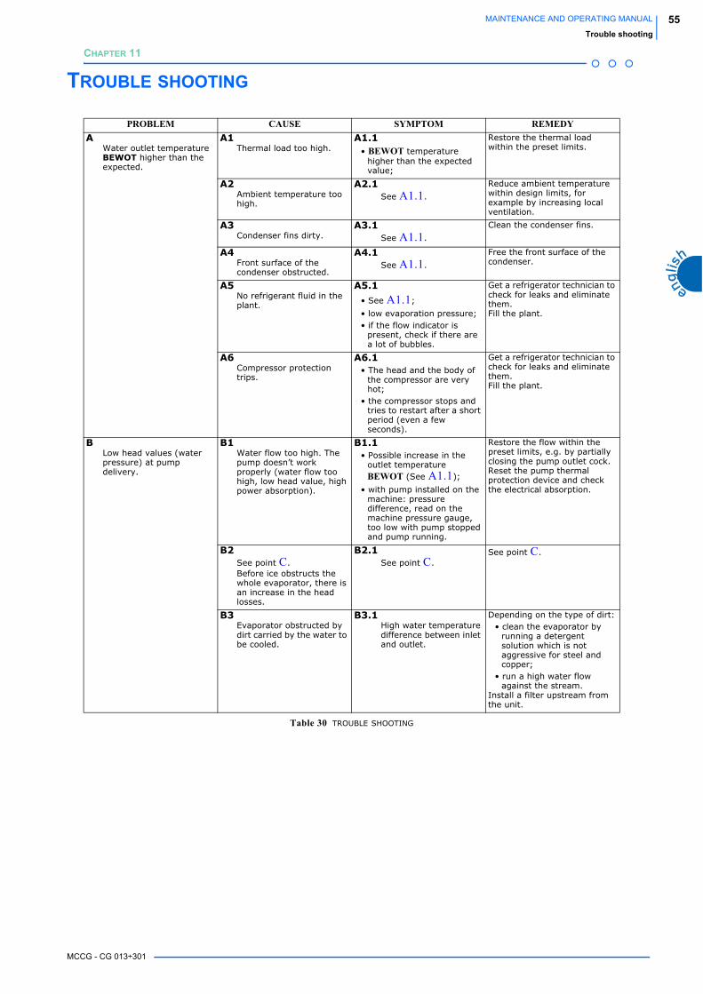
MCCG - CG 013÷301
55MAINTENANCE AND OPERATING MANUAL
Trouble shooting
CHAPTER 11
TROUBLE SHOOTING
PROBLEM CAUSE SYMPTOM REMEDYA
Water outlet temperature BEWOT higher than the expected.
A1Thermal load too high.
A1.1• BEWOT temperature
higher than the expected value;
Restore the thermal load within the preset limits.
A2Ambient temperature too high.
A2.1See A1.1.
Reduce ambient temperature within design limits, for example by increasing local ventilation.
A3Condenser fins dirty.
A3.1See A1.1.
Clean the condenser fins.
A4Front surface of the condenser obstructed.
A4.1See A1.1.
Free the front surface of the condenser.
A5No refrigerant fluid in the plant.
A5.1
• See A1.1;
• low evaporation pressure;• if the flow indicator is
present, check if there are a lot of bubbles.
Get a refrigerator technician to check for leaks and eliminate them.Fill the plant.
A6Compressor protection trips.
A6.1• The head and the body of
the compressor are very hot;
• the compressor stops and tries to restart after a short period (even a few seconds).
Get a refrigerator technician to check for leaks and eliminate them.Fill the plant.
BLow head values (water pressure) at pump delivery.
B1Water flow too high. The pump doesn’t work properly (water flow too high, low head value, high power absorption).
B1.1• Possible increase in the
outlet temperature BEWOT (See A1.1);
• with pump installed on the machine: pressure difference, read on the machine pressure gauge, too low with pump stopped and pump running.
Restore the flow within the preset limits, e.g. by partially closing the pump outlet cock.Reset the pump thermal protection device and check the electrical absorption.
B2See point C. Before ice obstructs the whole evaporator, there is an increase in the head losses.
B2.1See point C.
See point C.
B3Evaporator obstructed by dirt carried by the water to be cooled.
B3.1High water temperature difference between inlet and outlet.
Depending on the type of dirt:• clean the evaporator by
running a detergent solution which is not aggressive for steel and copper;
• run a high water flow against the stream.
Install a filter upstream from the unit.
Table 30 TROUBLE SHOOTING
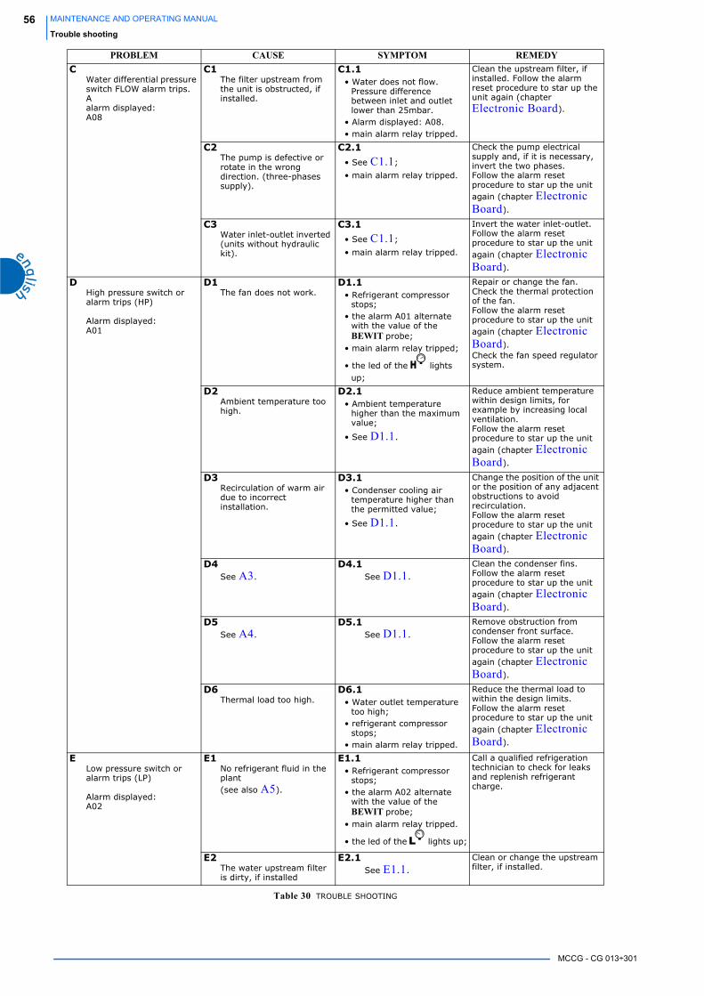
MCCG - CG 013÷301
56 MAINTENANCE AND OPERATING MANUAL
Trouble shooting
CWater differential pressure switch FLOW alarm trips.Aalarm displayed:A08
C1The filter upstream from the unit is obstructed, if installed.
C1.1• Water does not flow.
Pressure difference between inlet and outlet lower than 25mbar.
• Alarm displayed: A08.• main alarm relay tripped.
Clean the upstream filter, if installed. Follow the alarm reset procedure to star up the unit again (chapter Electronic Board).
C2The pump is defective or rotate in the wrong direction. (three-phases supply).
C2.1
• See C1.1;
• main alarm relay tripped.
Check the pump electrical supply and, if it is necessary, invert the two phases. Follow the alarm reset procedure to star up the unit again (chapter Electronic Board).
C3Water inlet-outlet inverted (units without hydraulic kit).
C3.1
• See C1.1;
• main alarm relay tripped.
Invert the water inlet-outlet.Follow the alarm reset procedure to star up the unit again (chapter Electronic Board).
DHigh pressure switch or alarm trips (HP)
Alarm displayed:A01
D1The fan does not work.
D1.1• Refrigerant compressor
stops;• the alarm A01 alternate
with the value of the BEWIT probe;
• main alarm relay tripped;
• the led of the lights up;
Repair or change the fan. Check the thermal protection of the fan.Follow the alarm reset procedure to star up the unit again (chapter Electronic Board).Check the fan speed regulator system.
D2Ambient temperature too high.
D2.1• Ambient temperature
higher than the maximum value;
• See D1.1.
Reduce ambient temperature within design limits, for example by increasing local ventilation.Follow the alarm reset procedure to star up the unit again (chapter Electronic Board).
D3Recirculation of warm air due to incorrect installation.
D3.1• Condenser cooling air
temperature higher than the permitted value;
• See D1.1.
Change the position of the unit or the position of any adjacent obstructions to avoid recirculation.Follow the alarm reset procedure to star up the unit again (chapter Electronic Board).
D4See A3.
D4.1See D1.1.
Clean the condenser fins.Follow the alarm reset procedure to star up the unit again (chapter Electronic Board).
D5See A4.
D5.1See D1.1.
Remove obstruction from condenser front surface.Follow the alarm reset procedure to star up the unit again (chapter Electronic Board).
D6Thermal load too high.
D6.1• Water outlet temperature
too high;• refrigerant compressor
stops;• main alarm relay tripped.
Reduce the thermal load to within the design limits. Follow the alarm reset procedure to star up the unit again (chapter Electronic Board).
ELow pressure switch or alarm trips (LP)
Alarm displayed:A02
E1No refrigerant fluid in the plant(see also A5).
E1.1• Refrigerant compressor
stops;• the alarm A02 alternate
with the value of the BEWIT probe;
• main alarm relay tripped.
• the led of the lights up;
Call a qualified refrigeration technician to check for leaks and replenish refrigerant charge.
E2The water upstream filter is dirty, if installed
E2.1See E1.1.
Clean or change the upstream filter, if installed.
PROBLEM CAUSE SYMPTOM REMEDY
Table 30 TROUBLE SHOOTING

MCCG - CG 013÷301
57MAINTENANCE AND OPERATING MANUAL
Trouble shooting
FThe compressor protection device trips.
Alarm displayed:A09 or A10
F1Thermal load too high combined with a situation of refrigerant circuit unloaded (also see A5).
F1.1• The head and the body of
the compressor are very hot;
• the compressor stops and tries to restart after a short period (even a few seconds).
• The compressor protection device trips
• Alarm displayed A09 or A10
• The led of the icon lights up.
Call a qualified refrigeration technician to check for leaks and replenish refrigerant charge.
F2The scroll compressor rotation direction is wrong (only three-phases units).
F2.1Refrigerant compressor stops the unit does not cool.
Invert two phases of the electrical supply.
GDigital display and all LEDs off, main switch P1 off (I).
G1The auxiliary board fuse trip.
G1.1Measuring with a tester the voltage at the transformer secondary winding connector, there will be not tension survey.
Check the causes of the fuse tripping.Replace the fuse.
G2Abnormal power consumption by one or more control board components.
G2.1Despite presence of power at the connectors of the control board, the display and all LEDs remain unlit.
Try to turn the unit OFF and ON again. If this doesn’t solve the problem, contact the nearest service centre.
HAlarm displayed:P1, P2, P3, P4
H1BEWIT, BEWOT, BCP1 or BAT1 probes damaged.
H1.1• See problem;• main alarm relay tripped.
Check that the temperature probe is correctly connected to the control board connectors and that the cable is undamaged. If necessary replace the temperature sensor.
IAlarm displayed:A04
I1Water outlet temperature too low.The value of the parameter Ar03 is higher then than the value measured by the BEWOT probe.
I1.1• see problem;• The compressor stops and
restarts when the Ar03+Ar04 value is exceeded;
• main alarm relay tripped.
• The led of the icon lights up.
Identify and remove the cause of BEWOT temperature decreasing to a value lower than Ar03.
I2 Water flow too low. I2.1• See problem;• The compressor stops and
restarts when the Ar03+Ar04 value is exceeded;
• main alarm relay tripped.
Increase the water flow.
PROBLEM CAUSE SYMPTOM REMEDY
Table 30 TROUBLE SHOOTING

MCCG - CG 013÷301
58 MAINTENANCE AND OPERATING MANUAL
Trouble shooting
JAlarm visualized:A11pump thermal protection
J1The thermal protection of the pump trips because the water flow is too high.
J1.1• See problem;• main alarm relay tripped;• the refrigerant compressor
and the pump stop; • the alarm A11 alternate
with the value of the BEWIT probe;
• the pressure difference read on the machine gauge with the pump stopped and pump running is lower than the available head with maximum pump flow.
Reset the thermal protection device.Increase the pressure drop in the hydraulic circuit, for example by partially closing the pump output valve.
J2The grille through which the pump cooling air passes is obstructed.
J2.1• see problem;• main alarm relay tripped;• the refrigerant compressor
and the pump stop.
Reset the thermal protection device. Free the grille.
J3The pump is defective.
J3.1• See problem;• main alarm relay tripped;• the refrigerant compressor
and the pump stop; • the current absorbed by
the pump is greater than the nominal rating;
• the pump may be noisy.
Reset the thermal protection device.Replace the pump.
KAlarmACF1,ACF2,ACF3,ACF4,ACF5
K1Configuration error.
K1.1ACFx blinks on the display and unit blocked
Turn off and turn on the unit. If this does not solve the problem, contact the nearest service centre.
LAlarmEE
L1The processor does not memorize the data in the right way
L1.1• The machine does not work• EE blinks on the display
• The led of the icon lights up.
Turn off and turn on the unit. If this does not solve the problem, contact the nearest service centre.
PROBLEM CAUSE SYMPTOM REMEDY
Table 30 TROUBLE SHOOTING


