
WATER PENETRATION RESISTANCE OF WINDOWS –
STUDY OF MANUFACTURING, BUILDING DESIGN, INSTALLATION AND MAINTENANCE FACTORS
Sponsors:
Canada Mortgage and Housing CorporationNational Office
700 Montreal Road
Ottawa, Ontario
K1A 0P7
Homeowner Protection OfficeSuite 2270 – 1055 W. Georgia Street
Vancouver, B.C.
V6E 3P3
British Columbia Housing Management CommissionHome Office
Suite 601 – 4555 Kingsway
Burnaby, BC
V5H 4V8
Submitted By:
RDH Building Engineering Limited
224 West 8th Avenue
Vancouver, B.C.
V5Y 1N5
December 31, 2002

Canada Mortgage and Housing Corporation, the Federal Government’s housing agency, is responsible for administering the
National Housing Act. This legislation is designed to aid in the development of housing and living conditions in Canada. As a
result, the Corporation has interests in all aspects of housing and urban growth and development. Under Part IX of this Act, the
Government of Canada provides funds to CMHC to conduct research into the social, economic and technical aspects of housing
and related fields, and to undertake the publishing and distribution of the results of this research. CMHC therefore has a
statutory responsibility to make widely available, information that may be useful in the improvement of housing and living
conditions. This publication is one of the many items of information published by CMHC with the assistance of federal funds.
Disclaimer: The analysis, interpretations and recommendations are those of the consultant and do not necessarily reflect the
views of Canada Mortgage and Housing Corporation or those divisions of the Corporation that assisted in the study and its
publication.

WATER PENETRATION RESISTANCE OF WINDOWS- STUDY OF MANUFACTURING, BUILDING DESIGN, INSTALLATION AND MAINTENANCE FACTORS
RDH
EXECUTIVE SUMMARY
The purpose of this study was to determine the primary leakage paths and causes of water penetration
associated with windows and the window to wall interface. Accomplishment of this goal facilitated
development of recommendations for various industry sectors in addressing water penetration issues.
The study does not address other performance issues associated with windows such as condensation
control, air tightness and structural adequacy.
A companion project to the current study addresses water penetration issues associated with windows in
the context of codes, standards and certification processes. The results of that study are reported on
separately in a report titled Water Penetration Resistance of Windows – Codes, Standards, Testing and
Certification.
Windows were grouped into generic types based on base frame material and rain penetration control
strategy so that a smaller number of window categories could be considered. Six primary leakage paths
through or around windows were established. A comprehensive list of causal factors that may contribute
to the various leakage paths was developed.
With this background established as context for the evaluation of windows and the window to wall
interface, the assessment proceeded with input from various industry sectors; manufacturing, testing and
certification, building & interface design and field review, installation, and maintenance and renewals. The
evaluation began with the assessment of the likelihood of particular leakage paths occurring for each
window type, and the level of consequential damage that may occur for each leakage path and window
type. Each window type was also assessed for the likelihood that particular causal factors contribute to a
leakage path. Finally, the potential impact that industry sectors can have in addressing the causal factors
was assessed.
The results of the study indicate that the dominant leakage paths of concern are those associated with the
window to wall interface, both through the window assembly to the adjacent wall assembly and through the
window to wall interface with the adjacent wall assembly. Consistent with this finding, it was noted that the
A440 B rating performance criteria for water penetration control does not identify leakage associated with
these leakage paths, nor is there a requirement for testing of the installed window assembly. A wide
range of causal factors were found to contribute to leakage activity.
A key study finding was the fact that the selection of windows and the design of the window to wall
interface failed to consider localized exposure conditions such as overhang protection provided by building
features, or the local topography. The Manufacturing sector and Building & Interface Design and Field
Review sectors have the most significant opportunities to impact positively on the performance of windows
and the window to wall interface.

WATER PENETRATION RESISTANCE OF WINDOWS- STUDY OF MANUFACTURING, BUILDING DESIGN,
INSTALLATION AND MAINTENANCE FACTORSRDH
The key recommendations include the assessment of micro exposure conditions in the specification and
selection of windows, as well as in the design of the window to wall interface. In general, all sectors need
to have a greater focus on the installed window and associated details. One of the key components of this
focus is the provision of some redundancy in water penetration control through the installation sub-sill
drainage. A water penetration testing protocol needs to be developed and mandated for the installed
window assembly.
RÉSUMÉ
La présente étude avait pour objet de déterminer les principaux parcours et les principales causes
d'infiltration d'eau par les fenêtres de même qu'à la jonction du mur et des fenêtres. La poursuite de ce
but a favorisé l'élaboration de recommandations en ce sens à l'intention de différents secteurs de
l'industrie. L'étude ne porte pas sur les autres questions de rendement associées aux fenêtres,
notamment la maîtrise de la condensation, l'étanchéité à l'air et la qualité structurale.
Des travaux menés parallèlement à la présente étude se penchent sur les problèmes d'infiltration d'eau
par les fenêtres en ce qui a trait aux codes, aux normes et aux processus de certification. On aborde
séparément les résultats de cette étude dans un rapport intitulé Water Penetration Resistance of Windows
– Codes, Standards, Certification and Harmonization.
Les fenêtres ont été rangées en types génériques d'après le matériau de base du dormant et la stratégie
de contrôle de pénétration de la pluie de façon à n'envisager qu'un nombre peu élevé de catégories de
fenêtres. Six principaux parcours d'infiltration par les fenêtres ou à leur pourtour ont été établis, puis la
liste complète des causes pouvant occasionner les différents parcours d'infiltration a été dressée.
Ces données documentaires constituant le contexte de l'évaluation des fenêtres et de leur interface avec
les murs, l'évaluation a été entreprise avec l'apport de différents secteurs de l'industrie : fabrication, essais
et certification, conception de bâtiments et des interfaces ainsi que vérification sur place, installation,
entretien et remplacement. L'évaluation a débuté par l'étude des probabilités que des parcours
d'infiltration d'eau particuliers se produisent pour chaque type de fenêtre, et de l'ampleur des dommages
consécutifs attribuables à chaque parcours d'infiltration et type de fenêtre. Chaque type de fenêtre a
également été étudié quant aux probabilités que des causes particulières entraînent un parcours
d'infiltration. Enfin, on a étudié l'incidence que les secteurs de l'industrie pourraient exercer en s'attaquant
aux causes.
Les résultats de l'étude révèlent que les parcours d'infiltration dominants posant le plus d'inquiétude sont
ceux qui se produisent à la jonction de la fenêtre et du mur, tant l'infiltration d'eau par la fenêtre se rendant
jusqu'au mur adjacent que l'infiltration d'eau à la jonction de la fenêtre et du mur parvenant jusqu'au mur
adjacent. Conformément à ce résultat, on a noté que la cote de performance B en matière de contrôle

WATER PENETRATION RESISTANCE OF WINDOWS- STUDY OF MANUFACTURING, BUILDING DESIGN, INSTALLATION AND MAINTENANCE FACTORS
RDH
d'infiltration d'eau prévue dans la norme A440 ne permet pas de cerner les infiltrations liées à ces
parcours, pas plus qu'il n'existe d'exigence pour mettre à l'essai la fenêtre une fois posée. Une vaste
gamme de causes, a-t-on découvert, contribue à la formation de parcours d'infiltration.
L'étude livre un important résultat : le choix des fenêtres et la conception de la jonction de la fenêtre et du
mur ne tiennent pas compte des conditions d'exposition localisée, comme la protection assurée par le
débord de toit ou la topographie des lieux. Les secteurs de la fabrication, de la conception des bâtiments
et des interfaces ainsi que de la vérification sur place disposent des occasions les plus appréciables d'agir
favorablement sur la performance des fenêtres et de leur jonction avec les murs.
Les recommandations clés touchent l'étude des conditions de micro-exposition dans la spécification et le
choix des fenêtres, de même que dans la conception de la jonction de la fenêtre et du mur. En général,
tous les secteurs doivent porter centrer davantage leur attention sur la fenêtre posée et les détails
d'exécution qui s'y rattachent. L'un des éléments clés de cette attention consiste à prévoir une certaine
redondance du contrôle de l'infiltration de l'eau en assurant l'évacuation sous la pièce d'appui de la
fenêtre. Il faudra établir un protocole d'essai d'infiltration d'eau et le rendre obligatoire pour la fenêtre
posée.

TABLE OF CONTENTS
Page
WATER PENETRATION RESISTANCE OF WINDOWS- STUDY OF MANUFACTURING, BUILDING DESIGN,
INSTALLATION AND MAINTENANCE FACTORSRDH
1. INTRODUCTION...........................................................................................................................1
1.1 Background.............................................................................................................................1
1.2 Objectives ...............................................................................................................................2
1.3 Project Team ..........................................................................................................................2
2. METHODOLOGY..........................................................................................................................3
2.1 General Approach...................................................................................................................3
2.2 Terminology ............................................................................................................................4
2.3 Window Types ........................................................................................................................7
2.4 Leakage Paths......................................................................................................................14
2.5 Causal Factors......................................................................................................................15
2.6 Assessment of Windows ......................................................................................................33
2.7 Industry Sector Follow-up .....................................................................................................34
3. SUMMARY OF RESULTS..........................................................................................................37
3.1 General .................................................................................................................................37
3.2 Leakage Paths......................................................................................................................37
3.3 Causal Factors......................................................................................................................39
3.4 Industry Sector Response to Assessment of Causal Factors ..............................................52
3.5 Comparison With Test Reports ............................................................................................63
4. CONCLUSIONS..........................................................................................................................67
4.1 Introduction ...........................................................................................................................67
4.2 Specific Conclusions.............................................................................................................68
5. RECOMMENDATIONS...............................................................................................................73
REFERENCES
APPENDIX A - TERMINOLOGY
APPENDIX B - SAMPLE WINDOW ASSESSMENT SHEET
APPENDIX C - SAMPLE INDUSTRY SECTOR FOLLOW-UP QUESTIONNAIRE

-1-
WATER PENETRATION RESISTANCE OF WINDOWS- STUDY OF MANUFACTURING, BUILDING DESIGN, INSTALLATION AND MAINTENANCE FACTORS
RDH
1. INTRODUCTION
1.1 Background
Over the past decade there has been an increasing number of reports of moisture related
performance problems in multi-unit residential buildings, particularly in British Columbia. Recent
studies of these moisture problems include the Survey of Envelope Failures in the Coastal Climate of
British Columbia1 (The Survey), Wall Moisture Problems in Alberta Dwellings
2 (Alberta Moisture
Study), and the Study of High-Rise Envelope Performance in the Coastal Climate of British Columbia3
(High-Rise Study). All three of these studies identify fabrication, installation and maintenance issues
associated with windows as a primary contributor to moisture problems in buildings.
Interestingly, building envelope performance problems and their close link to poor water penetration
resistance of windows and window to wall interfaces is a recurring theme in much of the moisture
related research and guidance documents that have been produced in Canada and elsewhere over
the last 40 years. In Glazing Design - Canadian Building Digest #554
(CBD55) published in July 1964,
it is stated that ‘Rain penetration is a major problem with glazing and must be controlled…’. A more
recent study Rain Leakage of Residential Windows in the Lower Mainland of British Columbia –
Building Practice Note No. 425 (BPN42) published the Division of Building Research, National
Research Council of Canada in November 1984 begins with ‘Many inquiries concerning rain
penetration of exterior wall are received by the B.C. Regional Station of the Division of Building
Research and are focused on window installation practices’. The problems are not restricted to BC
either. Building Research Note No. 2106 (BRN No. 210) also published in 1984 reports on window
performance problems in Atlantic Canada.
The CAN/CSA-A440-M, “Windows” 7 (A440) window performance standard and the accompanying
User Selection Guide8 (A440.1) were developed in part to help provide a basis for evaluating and
categorizing rain penetration control performance. More recently installation practices (A440.4
Window and Door Installation) have also been incorporated into a standard – CAN/CSA-A440.4M,
“Window and Door Installation”9 (A440.4).
Despite the various studies that have identified performance problems associated with windows, and
the introduction of new standards to improve quality, windows and window to wall interfaces continue
to be major contributors to moisture problems in buildings. The current study represents a
comprehensive effort to identify and establish priorities for improving in-service water penetration
resistance of windows and the window to wall interface. It is considered to be the first step in a

-2-
WATER PENETRATION REISTANCE OF WINDOWS- STUDY OF MANUFACTURING, BUILDING DESIGN,
INSTALLATION AND MAINTENANCE FACTORSRDH
process that will help the construction industry better understand the factors that influence water
penetration behaviour of windows and window to wall interfaces and more consistently result in
installed windows that perform well for their anticipated service lives.
A companion project to the current study addresses water penetration issues associated with windows
in the context of codes, standards and certification processes. The results of that study are reported
on separately in a report titled Water Penetration Resistance of Windows – Codes, Standards,
Testing, Certification and Harmonization10
(Companion Study).
1.2 Objectives
The primary objectives of the current study are to answer the following four key questions with respect
to water penetration resistance of windows and the window to wall interface:
• What are the important leakage paths?
• What are the primary causes of these leakage paths?
• What are the key improvements that need to be made to address these leakage paths and causal factors?
• What industry sector can best address these improvements?
The answers to these fundamental questions will establish focal points for the various industry sectors
in addressing water penetration issues on a consistent, integrated and systemic basis.
1.3 Project Team
The study was led by RDH Building Engineering Limited (RDH). Other team members representing
various industry sectors included Air-Ins Inc., Starline Windows, Toro Aluminum, Loewen Windows,
and Paul Kernan Architect. Much of the graphic material was prepared by Garcia Zunino Architects
Inc. In addition to these team members, many individuals within the various industry sectors were
consulted with respect to specific issues.

-3-
WATER PENETRATION RESISTANCE OF WINDOWS- STUDY OF MANUFACTURING, BUILDING DESIGN, INSTALLATION AND MAINTENANCE FACTORS
RDH
2. METHODOLOGY
2.1 General Approach
The assessment of water penetration associated with windows is complicated due to the large number
of variables that exist. Not only are there many different window types and manufacturers, there are
many potential leakage paths and causes of water penetration to be considered, some unique to
particular window types. In addition, windows are installed in a wide variety of wall assemblies with a
wide variety of interface details.
Our approach in undertaking this study therefore involved the following:
• Group windows into generic types so that we could consider a smaller number of window categories. These categories were established by considering the base frame material and the rain penetration control strategy that was utilized by the fixed window unit in each generic type.
• Establish primary leakage paths through and around windows with eventual destinations for the water including the interior of the building, the adjacent wall assembly, and concealed space within the window assembly.
• Develop a comprehensive list of causal factors (specific issues that may result in leakage) that could be evaluated in the context of particular leakage paths and window types.
• Assess the likelihood of particular leakage paths occurring for each window type.
• Assess the level of consequential damage that may occur due to various leakage paths for each window type.
• Assess each window type for the likelihood that a causal factor contributes to a leakage path.
• Assess the potential impact that various sectors of the industry could have in addressing the various causal factors.
• Develop conclusions and priorities with respect to causal factors, leakage paths, and industry sector impact for each window type.
• Develop recommendations for addressing water penetration issues based on the previous analysis.
• Prepare report that summarizes the results of the study.
• Prepare graphical support package that illustrates all aspects of the study and provides an interactive tool for the selection, detailing, installation, maintenance and renewals of various types of windows.
The study includes windows and water penetration issues associated with both low-rise wood frame
buildings and high-rise non-combustible buildings. It also includes window-wall technology (see
Terminology in Appendix A), but does not include curtainwall technology.

-4-
WATER PENETRATION REISTANCE OF WINDOWS- STUDY OF MANUFACTURING, BUILDING DESIGN,
INSTALLATION AND MAINTENANCE FACTORSRDH
2.2 Terminology
Many of the technical terms used in this report are defined in Appendix A. Several of the terms have
meanings specific to this report and may not represent the generally accepted definitions used within
parts of the industry. In particular, terminology related to critical barriers and water penetration control
strategies are used and are important to understand in order to appreciate the results of this study.
Critical Barriers
Critical barrier refers to materials and components that together perform a specific function within a
wall or window assembly. All of these functions are ‘critical’ to the successful performance of the
assembly however, some of the functions are easier to achieve than others. It is common to think of,
and define, critical barriers within a wall assembly such as a vapour barrier or air barrier. We have
introduced two additional barriers that are not as well understood or used within the industry. All four
barriers are discussed in the context of walls and windows.
One of these critical barrier terms is the water shedding surface. The water shedding surface refers
to the surface of assemblies, interfaces and details that deflect and/or drain the vast majority of
exterior moisture (in the form of liquid water) impacting on the façade.
A second less well understood critical barrier term is the exterior moisture barrier (can also be referred
to as a water resistive barrier). The exterior moisture barrier refers to the surface farthest into an
assembly from the exterior that can accommodate some exterior moisture (in the form of liquid water)
without causing damage to interior finishes or materials within the assemblies.
The differing functions of these four critical barriers are probably best understood by examining a
simple wall assembly. In the simple example shown in Figure 2.2-1 the vapour barrier is the
polyethylene sheet. If we assume that an air-tight drywall approach is utilized then the air barrier is the
interior gypsum board. The exterior moisture barrier is the sheathing paper since any moisture to the
outside of this surface is able to drain or dry to the exterior whereas moisture located to the interior of
this material will wet or damage moisture susceptible materials such as the sheathing and studs and
is not able to readily drain or dry. The exterior surface of the stucco is the water shedding surface in
this assembly, and deflects the vast majority of the exterior moisture (rain) that impacts on the surface
of the wall.

-5-
WATER PENETRATION RESISTANCE OF WINDOWS- STUDY OF MANUFACTURING, BUILDING DESIGN, INSTALLATION AND MAINTENANCE FACTORS
RDH
Figure 2.2-1: Critical Barriers for Typical Wall Assembly
Exterior
Stucco cladding
Air Space
Sheathing Paper
Exterior Sheathing
Insulated Stud Space
Polyethylene Sheet
Interior Gypsum Board
Interior
Critical Barriers:
Vapour Barrier
Air Barrier
Exterior Moisture Barrier
Water Shedding Surface
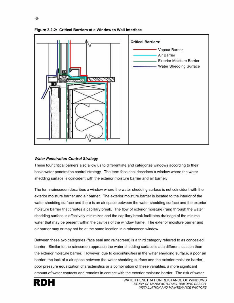
The four critical barriers can also be used to describe different functions within window assemblies
and at interfaces between windows and wall assemblies. See Figure 2.2-2. In this example the
vapour barrier (resisting vapour diffusion) is provided by materials of low vapour permeability located
near the interior of the wall and window assembly and including the polyethylene sheet, window frame,
and the interior sheet of glass. The air barrier (resisting the flow of air in either direction) is provided
by the drywall, seal to the sub-sill, seal between the sub-sill and the window frame, the window frame,
the seal between the window frame and the glazing, and the glazing. The exterior moisture barrier
function is provided by the glazing, the seal between the glazing and the window frame, the seal
between the window frame and the sub-sill membrane, the sub-sill membrane, and the exterior
sheathing paper. The water shedding surface function consists of the glazing, the glazing tape
between the glazing and window frame, the exterior surface of the window frame, the sealant between
the window frame and the sill drip flashing, the sill drip flashing and the exterior surface of the stucco
cladding.
Exterior Interior
-6-
WATER PENETRATION REISTANCE OF WINDOWS- STUDY OF MANUFACTURING, BUILDING DESIGN,
INSTALLATION AND MAINTENANCE FACTORSRDH
Figure 2.2-2: Critical Barriers at a Window to Wall Interface
Critical Barriers:
Vapour Barrier
Air Barrier
Exterior Moisture Barrier
Water Shedding Surface
Water Penetration Control Strategy
These four critical barriers also allow us to differentiate and categorize windows according to their
basic water penetration control strategy. The term face seal describes a window where the water
shedding surface is coincident with the exterior moisture barrier and air barrier.
The term rainscreen describes a window where the water shedding surface is not coincident with the
exterior moisture barrier and air barrier. The exterior moisture barrier is located to the interior of the
water shedding surface and there is an air space between the water shedding surface and the exterior
moisture barrier that creates a capillary break. The flow of exterior moisture (rain) through the water
shedding surface is effectively minimized and the capillary break facilitates drainage of the minimal
water that may be present within the cavities of the window frame. The exterior moisture barrier and
air barrier may or may not be at the same location in a rainscreen window.
Between these two categories (face seal and rainscreen) is a third category referred to as concealed
barrier. Similar to the rainscreen approach the water shedding surface is at a different location than
the exterior moisture barrier. However, due to discontinuities in the water shedding surface, a poor air
barrier, the lack of a air space between the water shedding surface and the exterior moisture barrier,
poor pressure equalization characteristics or a combination of these variables, a more significant
amount of water contacts and remains in contact with the exterior moisture barrier. The risk of water

-7-
WATER PENETRATION RESISTANCE OF WINDOWS- STUDY OF MANUFACTURING, BUILDING DESIGN, INSTALLATION AND MAINTENANCE FACTORS
RDH
penetration for a concealed barrier window (or wall) usually falls somewhere between a face seal
window (higher risk) and a rainscreen window (lower risk). However, it is possible for the performance
of concealed barrier windows to be less effective than face seal windows. This is due to the fact that
water can be retained inside the frame, in contact with sealants thereby adversely affecting the
durability of the sealant due to constant water immersion. In addition, because water is sometimes
retained within concealed spaces in the frame, frequency and quantity of water leakage through the
frame can be more prevalent. The effective performance of concealed barrier windows is therefore
dependent on the management of the variables described above (continuity of water shedding
surface, location and continuity of air barrier, and drainage capability between the water shedding
surface and the exterior moisture barrier).
2.3 Window Types
Grouping the windows into generic types was accomplished through reference to the basic frame
material (aluminum, vinyl or wood) and the water penetration control strategy. Fibreglass windows
were not included due to their very small market share and the fact that only minimal performance
history and experience exists. Hybrid aluminum-vinyl, and aluminum-wood windows also exist but
were not included as distinct window types in the study. In both cases the performance of the window
could be referenced to the base material (vinyl or wood), with the aluminum acting primarily as a
cladding attached to the frame section.
Operable unit types are considered to be separate components of a particular window type. The
sketches illustrating generic window types used in this report and in the graphical presentation
package (appended to report) represent one configuration of each type. Other possibilities exist
provided that they share the basic water penetration strategy and base material. The key when
assessing a particular window assembly is therefore to be able to identify the fundamental water
penetration control strategy. For example, the two window frame sections shown in Figure 2.3-1 can
both be classified as aluminum face seal windows despite their very different configurations. The dark
blue line indicates the location of the water shedding surface while the green line indicates the location
of the exterior moisture barrier.

-8-
WATER PENETRATION REISTANCE OF WINDOWS- STUDY OF MANUFACTURING, BUILDING DESIGN,
INSTALLATION AND MAINTENANCE FACTORSRDH
Figure 2.3-1: Two Different Configurations of Aluminum Face Seal Windows
WATER SHEDDING SURFACE EXTERIOR MOISTURE BARRIER
The following tables (2.3-2 to 2.3-4) describe the 10 window categories that were identified as distinct
window types and were specifically examined within the study.
Figure 2.3-2: Aluminum Window Types
WATER SHEDDING SURFACE EXTERIOR MOISTURE BARRIER
AL-1: Aluminum Face Seal

-9-
WATER PENETRATION RESISTANCE OF WINDOWS- STUDY OF MANUFACTURING, BUILDING DESIGN, INSTALLATION AND MAINTENANCE FACTORS
RDH
WATER SHEDDING SURFACE EXTERIOR MOISTURE BARRIER
AL-2: Aluminum Concealed Barrier
AL-3: Aluminum Concealed Barrier (Improved)
Al-4: Aluminum Rainscreen

-10-
WATER PENETRATION REISTANCE OF WINDOWS- STUDY OF MANUFACTURING, BUILDING DESIGN,
INSTALLATION AND MAINTENANCE FACTORSRDH
WATER SHEDDING SURFACE EXTERIOR MOISTURE BARRIER
AL-5: Aluminum Rainscreen Slider
Figure 2.3-3: Vinyl Window Types
WATER SHEDDING SURFACE EXTERIOR MOISTURE BARRIER
V-1: Vinyl Face Seal

-11-
WATER PENETRATION RESISTANCE OF WINDOWS- STUDY OF MANUFACTURING, BUILDING DESIGN, INSTALLATION AND MAINTENANCE FACTORS
RDH
WATER SHEDDING SURFACE EXTERIOR MOISTURE BARRIER
V-2: Vinyl Concealed Barrier
V-3: Vinyl Rainscreen
-12-
WATER PENETRATION REISTANCE OF WINDOWS- STUDY OF MANUFACTURING, BUILDING DESIGN,
INSTALLATION AND MAINTENANCE FACTORSRDH
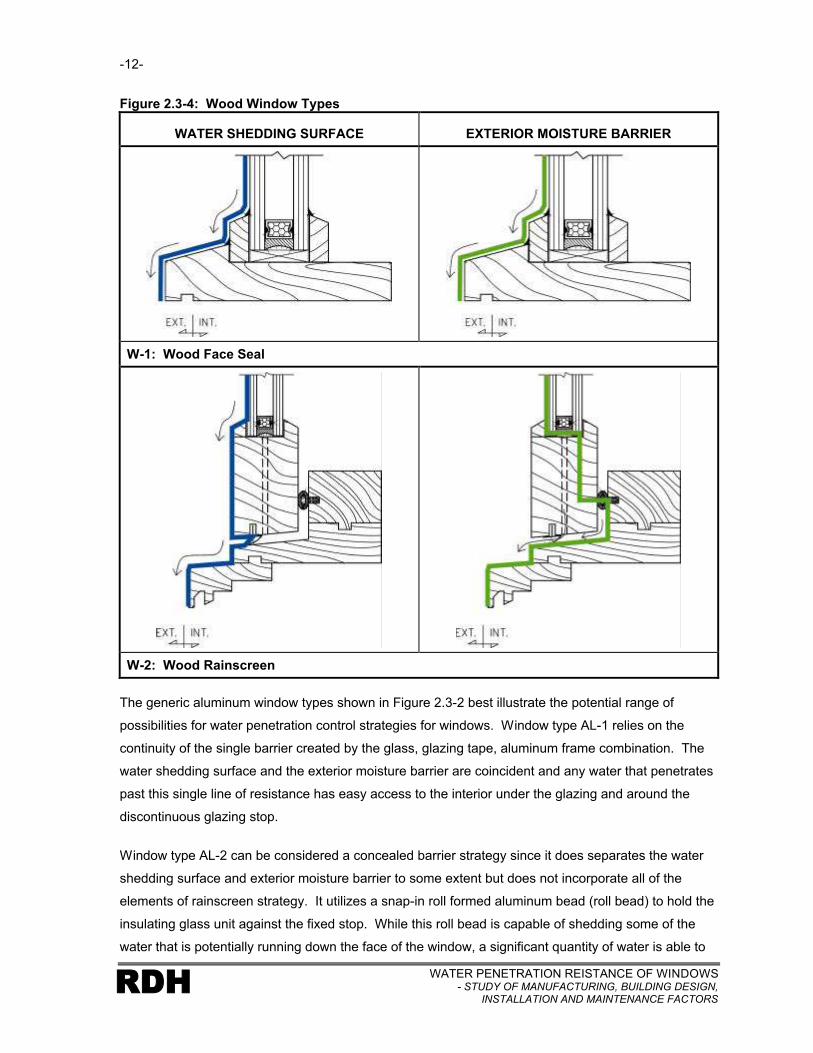
Figure 2.3-4: Wood Window Types
WATER SHEDDING SURFACE EXTERIOR MOISTURE BARRIER
W-1: Wood Face Seal
W-2: Wood Rainscreen
The generic aluminum window types shown in Figure 2.3-2 best illustrate the potential range of
possibilities for water penetration control strategies for windows. Window type AL-1 relies on the
continuity of the single barrier created by the glass, glazing tape, aluminum frame combination. The
water shedding surface and the exterior moisture barrier are coincident and any water that penetrates
past this single line of resistance has easy access to the interior under the glazing and around the
discontinuous glazing stop.
Window type AL-2 can be considered a concealed barrier strategy since it does separates the water
shedding surface and exterior moisture barrier to some extent but does not incorporate all of the
elements of rainscreen strategy. It utilizes a snap-in roll formed aluminum bead (roll bead) to hold the
insulating glass unit against the fixed stop. While this roll bead is capable of shedding some of the
water that is potentially running down the face of the window, a significant quantity of water is able to

-13-
WATER PENETRATION RESISTANCE OF WINDOWS- STUDY OF MANUFACTURING, BUILDING DESIGN, INSTALLATION AND MAINTENANCE FACTORS
RDH
move past the clip due to discontinuities at joints in the clip at window corners and the poor fit or seal
against the glass and access the glazing cavity. In addition, holes have been provided through the
fixed glazing leg to allow for drainage of an internal gutter. This results in a poor air barrier at this
location in the assembly and therefore less than ideal pressure equalization characteristics. The
pressure drop that occurs over the roll bead will tend to draw more water into the glazing cavity.
Combined with the discontinuous nature of the roll bead (water shedding surface) this leads to a
significant amount of water in contact with the exterior moisture barrier which includes the vulnerable
mitre joints and screw penetrations between components of the frame.
Window type AL-3 while still a concealed barrier strategy, has some improvements. The air barrier is
now continuous since there are no holes through the fixed stop and the removable glazing stop
consists of heavier gage extruded aluminum with a neoprene or vinyl gasket which provides improved
continuity of the water shedding surface and compression of the gasket against the glass. However, a
lack of continuity in the water shedding surface still occurs to some extent, where the gasket and the
extruded aluminum stop terminate at corners.
Window type AL-4 utilizes a rainscreen strategy for control of water penetration. It incorporates a
separate water shedding surface and exterior moisture barrier. The water shedding surface consists
of the glass, glazing tape and window frame. The exterior moisture barrier consists of the glazing unit
(including both lites of glass and the seal between them), the heal bead of sealant and the bottom
surface of the window frame which is drained to the exterior. The air barrier is coincident with the
exterior moisture barrier. The key difference between this window type and that shown for AL-3 is the
effectiveness of the water shedding surface. While window type AL-5 utilizes a similar rainscreen
strategy the configuration of the window components is quite different.
It is worth noting that while the window assembly (and the window to wall interface) can generally be
categorized based on the water penetration control strategy as described above, the glazing portion in
most windows utilizes a face seal strategy. Its success is attributable to the material properties of the
glass (continuous, air and vapour impermeable, non-absorbent). It is therefore possible to effectively
integrate this face seal component with and concealed barrier and rainscreen rain penetration control
strategies.
For the purposes of this study rainscreen windows are not required to have a slope surface for the
drained cavities. This is often considered an element of detailing that is part of rainscreen design.
For example, the generic frame sections shown for rainscreen window types AL-4 and V-3 do not
have sloped surface in the drainage cavity, while windows types AL-5 and W-2 do utilize sloped
surfaces.

-14-
WATER PENETRATION REISTANCE OF WINDOWS- STUDY OF MANUFACTURING, BUILDING DESIGN,
INSTALLATION AND MAINTENANCE FACTORSRDH
L3
L6
L1
L4
L5
L2
Although the generic window frame sections shown generally depict fixed glazing situations, similar
water penetration control strategies are used within the sash of operable windows. However, it is
common for the interface between the sash and the window frame to utilize a rainscreen strategy
regardless of the strategy used for the fixed glazing. This is best illustrated by window type W-2 since
the fixed and operable unit configurations are similar. The water shedding surface relies on the
surface of the window frame as well as a gasket and sloped sill located under the sash. This gasket
(in a rainscreen window or interface) is discontinuous facilitating drainage from the cavity around the
sash as well as improving pressure equalization characteristics. The exterior moisture barrier (and air
barrier) utilizes the sash, a continuous gasket located on the vertical surface between the sash and
the frame, and the sloped sill portion of the frame.
2.4 Leakage Paths
Six possible leakage paths were established as those to be considered during our assessment of the
various window types and the window to wall interface. These are shown and described in
Figure 2.4-1.
Figure 2.4-1: Possible Window Leakage Paths
Leakage Paths:
L1 - Through fixed unit to interior (includes through fixed portion of sash)
L2 - Around operable unit to interior
L3 - Through window to wall interface to interior (head, sill and jambs, also includes leakage at coupler mullions or corner posts between two adjacent window assemblies)
L4 - Through window assembly to adjacent wall assembly
L5 - Through window to wall interface to adjacent wall assembly (head, sill and jambs, also includes leakage at coupler mullions or corner posts between two adjacent window assemblies)
L6 - Through window assembly to concealed compartments within window assembly (includes frame sections that do not drain and spandrel cavities within window walls)

-15-
WATER PENETRATION RESISTANCE OF WINDOWS- STUDY OF MANUFACTURING, BUILDING DESIGN, INSTALLATION AND MAINTENANCE FACTORS
RDH
A key goal for this study is the determination of which of the six leakage paths are most significant in
terms of frequency of occurrence and risk of consequential damage.
2.5 Causal Factors
The occurrence of a particular water leakage path can always be related to one or more causal
factors. A comprehensive list of these factors was developed so that their relative contribution could
be assessed with respect to each window type and leakage path. The causal factors were grouped
into six general categories:
• Sealants
• Gaskets and Tapes
• Penetrations
• Components
• Window Design and Selection
• Quality Assurance / Quality Control
The following sections describe each of the causal factors within these six categories:
Sealants
Sealants are used at a variety of locations and are subject to wide ranging environmental conditions
and stresses (UV exposure, temperature movement, wetting, contact with other materials) depending
on the particular application within the window and wall assemblies. The extensive range of sealant
materials available further complicates the behaviour of sealants in windows. As a result there are a
number of potential sealant failure locations and several modes of failure that could occur at each of
these locations. Table 2.5-1 describes potential sealant locations within the window assembly while
Table 2.5-2 describes various failure modes. The photographs or figures are examples of the sealant
location or failure mode described.
In assessing the potential for sealants to contribute to a failure for a particular window type, it was
necessary to consider first the particular location of the sealant and the likelihood of the various failure
modes for that location. This two stage evaluation approach was unique to sealants in the
assessment of the causal factors.

-16-
WATER PENETRATION REISTANCE OF WINDOWS- STUDY OF MANUFACTURING, BUILDING DESIGN,
INSTALLATION AND MAINTENANCE FACTORSRDH
Table 2.5-1: Sealant LocationsBetween Fixed Frame Members – Sealant is used (typically bedded or filet bead between frame members at butt or mitre joints, or at adapter to frame joint) where two members are screwed together. Movement at these joints due to environmental loads is very small however, racking during manufacturing, transportation or installation can cause excessive movement.
The area highlighted by the red circle in the photograph indicates an example of a leakage location between vertical and horizontal frame members at a butt joint.
Between Couplers – Window frame sections and coupler mullions are typically fit together with mating extrusions without the use of fasteners. Sealant is used either concealed within the joint or on the surface between the two frame members. Movement at these joints due to environmental loads can be considerable depending on width of adjacent windows.
The arrow in the photograph indicates sealant applied at a vertical joint between the window frame and coupler extrusion.
Perimeter Water Shedding Surface Seal – The joint between the window frame members is often sealed to the adjacent cladding materials that from part of the water shedding surface with a caulked joint. Stresses resulting from movement at these joints can be small or large depending on the joint configuration, sealant material used and the size of the window.
The arrow in the photograph indicates a cohesive failure of sealant located between the stucco cladding and the window header and forming part of the water shedding surface.

-17-
WATER PENETRATION RESISTANCE OF WINDOWS- STUDY OF MANUFACTURING, BUILDING DESIGN, INSTALLATION AND MAINTENANCE FACTORS
RDH
Perimeter Exterior Moisture Barrier Seal – The joint between the window frame members is often sealed to adjacent materials that form part of the exterior moisture barrier with a caulked joint. Movement at these joints can be small or large depending on the nature of the joint, the location within the assembly (closer to the interior or exterior) and material used for the adjacent materials.
The arrow in the photograph indicates an area of sealant removed from the joint in the exterior moisture barrier at a face seal interface between a window and adjacent face seal wall assembly.
Cap Bead at Glazing Units – A bead of sealant can be used on the exterior side of the glazing unit between the frame members and the outer sheet of glass. It is often done as a supplementary seal over the primary glazing tape seal between the glass and the frame.Movement at these joints due to environmentalloads varies depending on the base fame material.
The arrow in the photograph indicates a cap bead of sealant applied between glazing and horizontal frame section over the glazing tape.
Heel Bead to Glazing Units – Sealant can be used to create a seal between the glazing and the frame members at an inner protected location. This seal can form part of the air barrier and exterior moisture barrier in a rainscreen assembly. Movement due to environmental loads is small due to its interior location, UV exposure is less, however it can be exposed to some wetting from the exterior.
The arrow in the photograph indicates a heel bead of sealant applied between the interior side of the glazing unit and the window frame to form part of the exterior moisture barrier and air barrier in this rainscreen window.

-18-
WATER PENETRATION REISTANCE OF WINDOWS- STUDY OF MANUFACTURING, BUILDING DESIGN,
INSTALLATION AND MAINTENANCE FACTORSRDH
Back Pan – Sealant is used to seal back pans to window frames. Typically it is bedded between the frame member and the back pan or used in a filet joint. Movement due to environmental loads is small due to its interior location and the minimal movement capability between the back pan and the window frame member.
The arrow in the photograph indicates a filet bead of sealant applied to seal the back pan in the spandrel area of a window-wall forming part of the exterior moisture barrier and air barrier.
Head Flashing Segmented Joint –Sealant is used between two lapped sections of head flashing. Movement due to environmental loads at these joints can be considerable depending on the length of the adjacent sections of flashing and the method of attachment.
The arrow in the photograph indicates the poorly sealed mitre joint in a deflection header.
Sill Flashing Segmented Joint – Sealant is used between two lapped sections of sill flashing. Movement due to environmental loads at these joints can be considerable depending on the length of the adjacent sections of flashing and the method of attachment.
The arrow in the photograph indicates a sealed mitre joint in a window sill flashing.

-19-
WATER PENETRATION RESISTANCE OF WINDOWS- STUDY OF MANUFACTURING, BUILDING DESIGN, INSTALLATION AND MAINTENANCE FACTORS
RDH
Brick Mold to Window Frame – It is common to add an exterior trim piece to a window frame (commonly referred to as a brick mold) to facilitate the transition to adjacent cladding.Sealant is used to seal between the brick mold and the frame member (typically bedded between the two or a filet bead). Movement due to environmental loads is small however the sealant may be exposed on the exterior.
The arrow in the photograph indicates an exterior trim board attachment for a wood window frame.
Fasteners – Sealant is used over the heads of screws and clips to improve water tightness of fastener penetration. Movement due to environmental loads is small however sealant may be exposed to exterior conditions.
The arrow in the photograph indicates sealant applied at the head of a fastener connecting window frame sections.
Table 2.5.2: Sealant Failure ModeInappropriate Choice of Sealant Type – Sealants have varying movement capabilities, UV resistance, compatibility with other materials and adhesion properties.The use of the wrong sealant for a particular application can result in failure regardless of other factors.Failure contributes to water penetration at the joint.

-20-
WATER PENETRATION REISTANCE OF WINDOWS- STUDY OF MANUFACTURING, BUILDING DESIGN,
INSTALLATION AND MAINTENANCE FACTORSRDH
Poor Surface Preparation – Surface preparation is critical to the sealants ability to adhere to a surface. Poor preparation can result in debonding of the sealant from the substrate material. In some cases the base material may be unsuitable for adhesion (acrylic finish coat). Failure contributes to water penetration at the joint.
The arrow in the photograph indicates debonding of sealant at a window perimeter due to the adhesive characteristics of a coating that had been applied to the substrate.
Sealant Weathering – Sealant subjected to prolonged exposure to ultra violet rays, moisture or cyclic movement will loose its elastic properties, dry out, crack, chalk and fail (reversion, fatigue, UV degradation). Various sealants are more or less resistant to these weathering phenomena. The failure of the sealant contributes to water penetration at the joint.
The arrow in the photograph indicates weathered sealant between the sill of a window and metal sill flashing characterized in this example by cracking, and loss of elastic properties.
Discontinuous Application – Missing sealant at a location allows water penetration to occur at the joint.
The arrow in the photograph indicates an area of missing sealant at the perimeter of a window.

-21-
WATER PENETRATION RESISTANCE OF WINDOWS- STUDY OF MANUFACTURING, BUILDING DESIGN, INSTALLATION AND MAINTENANCE FACTORS
RDH
Poor Joint Configuration – Poor joint configuration (size, aspect ratio) can result in excessive stress build-up at the joint and failure of the sealant either cohesively, or adhesively at the substrate. The failure contributes to water penetration at the joint.
Gaskets And Tapes
Gaskets and glazing tapes are used between the glazing unit and either fixed or removable glazing
stops. Gaskets are also used between window sash and window frame members. Gaskets typically
rely upon compression to create a seal (dry seal) whereas glazing tapes rely upon adhesion to the two
adjacent surfaces to create a seal (wet seal). Gaskets and tapes may or may not form part of the air
barrier, exterior moisture barrier or water shedding surface. As a result, failure of these components
may or may not have an impact on the overall water tightness of the window and window to wall
interfaces depending on its function for a particular window type. Table 2.5.3 describes potential
gasket and tape failure modes.
Table 2.5.3: Gaskets and TapesDiscontinuous Glazing Tape –Discontinuities in the glazing tape may result in a corresponding failure in the air barrier, exterior moisture barrier or water shedding functions which could in turn contribute to water penetration. The significance of discontinuous glazing tape is dependent on its function(s).
The arrow in the photograph indicates discontinuous glazing tape at the corner of window resulting in a discontinuity of the water shedding surface of the window.
-22-
WATER PENETRATION REISTANCE OF WINDOWS- STUDY OF MANUFACTURING, BUILDING DESIGN,
INSTALLATION AND MAINTENANCE FACTORSRDH
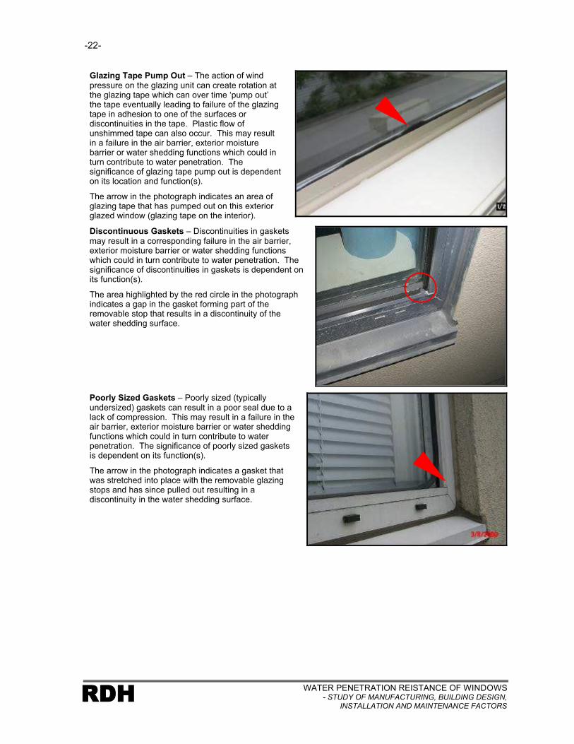
Glazing Tape Pump Out – The action of wind pressure on the glazing unit can create rotation at the glazing tape which can over time ‘pump out’ the tape eventually leading to failure of the glazing tape in adhesion to one of the surfaces or discontinuities in the tape. Plastic flow of unshimmed tape can also occur. This may result in a failure in the air barrier, exterior moisture barrier or water shedding functions which could in turn contribute to water penetration. The significance of glazing tape pump out is dependent on its location and function(s).
The arrow in the photograph indicates an area of glazing tape that has pumped out on this exterior glazed window (glazing tape on the interior).
Discontinuous Gaskets – Discontinuities in gaskets may result in a corresponding failure in the air barrier, exterior moisture barrier or water shedding functionswhich could in turn contribute to water penetration. The significance of discontinuities in gaskets is dependent on its function(s).
The area highlighted by the red circle in the photograph indicates a gap in the gasket forming part of the removable stop that results in a discontinuity of the water shedding surface.
Poorly Sized Gaskets – Poorly sized (typically undersized) gaskets can result in a poor seal due to a lack of compression. This may result in a failure in the air barrier, exterior moisture barrier or water shedding functions which could in turn contribute to water penetration. The significance of poorly sized gaskets is dependent on its function(s).
The arrow in the photograph indicates a gasket that was stretched into place with the removable glazing stops and has since pulled out resulting in a discontinuity in the water shedding surface.

-23-
WATER PENETRATION RESISTANCE OF WINDOWS- STUDY OF MANUFACTURING, BUILDING DESIGN, INSTALLATION AND MAINTENANCE FACTORS
RDH
Poor Fit of Gaskets – Poor fit of gaskets (poor shape of gasket material or mating surfaces, operating hardware characteristics, weathering or shrinkage of gasket material) can result in poor compression or water ponding on the gasket material. This may result in a failure in the air barrier, exterior moisture barrier or water shedding functions which could in turn contribute to water penetration. The significance of poor fit of gaskets is dependent on its function(s).
The arrow in the photograph indicates a gasket with inadequate compression resulting in failure of the exterior moisture barrier.
Penetrations
Other equipment or services can penetrate the window assembly and compromise the water tightness
of the assembly. Some of these penetrations pass through the frame members while others pass
through panels within a spandrel area. Table 2.5.4 describes failure modes for several types of
penetrations.
Table 2.5.4: PenetrationsFire Place Vent – Fire place vents typically are integrated into metal or glass panels within the window assembly. The surrounding panel can be integrated into the window using conventional spandrel panel techniques. However, the ineffective connection of the fire place vent assembly to the metal panel can create an opportunity for water to penetrate either directly through the window assembly or into the assembly.
The arrow in the photograph indicates a fireplace vent installed through a glazed spandrel area in a window-all assembly.

-24-
WATER PENETRATION REISTANCE OF WINDOWS- STUDY OF MANUFACTURING, BUILDING DESIGN,
INSTALLATION AND MAINTENANCE FACTORSRDH
Dryer Ducts – Dryer ducts typically exhaust either through in-slab or floorducts and an integrated vent hood assembly within a slab area spandrel panel or through a penetration through a metal panel located just below the floor. In either case the lack of continuity between the duct and vent hood components and the window assembly components can create a source of water penetration through or into the window assembly.
The arrow in the photograph indicates a dryer exhaust location that has been integrated into the slab spandrel area of a window-wall assembly.
Electrical Cables – Electrical cables sometimes pass through panel or frame components of the window to access exterior lighting or plug fixtures. A poorly located or detailed penetration can result in water penetration through or into the window assembly.
The arrow in the photograph indicates an electrical box penetration within a glazed spandrel area.
Security Hardware – Security hardware is typically provided to operable window units by drilling holes through frame components.The poor location or detailing of this penetration can lead to water penetration through or into the window assembly. The hardware is typically installed after the window installers have completed their work.
The arrow in the photograph indicates a hole drilled through a window frame for a security system installation.

-25-
WATER PENETRATION RESISTANCE OF WINDOWS- STUDY OF MANUFACTURING, BUILDING DESIGN, INSTALLATION AND MAINTENANCE FACTORS
RDH
Components
The incorrect use or application of the components of an installed window assembly can result in, or
contribute to, water penetration. Table 2.5.5 describes potential window component failure modes.
Table 2.5.5: ComponentsWeld Failure at Mitre – The mitre joints (and sometimes butt joints) of vinyl windows are heat welded. Failure of these welds due to excessive stress, poor welding or other activity can lead to water penetration past the frame.
The arrow in the photograph indicates a failure of a welded mitre in a vinyl window.
Incomplete Weld – A lack of continuity in the weld of mitre or butt joints in vinyl windows can lead to water penetration past the frame.
The arrow in the photograph indicates an incomplete welded mitre in a vinyl window.
Lack of Fasteners – Fasteners are required both toattach the frame to the rough opening and to fasten components of the frame together. A missing or failed fastener at either location could contribute to a water penetration problem due to increased movement of the frame or increased stress on sealants.
The arrow in the photograph indicates a location where the head of a fastener has broken off.

-26-
WATER PENETRATION REISTANCE OF WINDOWS- STUDY OF MANUFACTURING, BUILDING DESIGN,
INSTALLATION AND MAINTENANCE FACTORSRDH
Corrosion of Fasteners – Fasteners are required both to attach the frame to the rough opening and to fasten components of the frame together. Failure of thefastener due to corrosion could contribute to a water penetration problem due to increased movement of the frame or increased stress on sealants.
The highlighted area in the photograph indicates several corroded screws used for retaining the window mullion to a clip at the floor slab for this window-wallassembly.
Poor Seal Between Vent Adapter and Frame – An adapter (framing within the main window frame) is usually required in order to install an operable window vent within a window. A poor seal or discontinuous seal between the adapter framing and the main window framing can lead to water penetration.
Lack of Slope on Head Flashing – A lack of slope (or back sloping) on head flashing can result in water ponding and being directed off the ends of the flashing at the interface between the window and the adjacent wall assembly which in turn can contribute to water penetration.
The arrow in the photograph indicates a section of back sloped flashing at the head of a window.
Lack of Slope on Sill Flashing – A lack of slope (or back sloping) on sill flashing can result in water ponding and being directed off the ends of the flashing at the interface between the window and the adjacent wall assembly which in turn can contribute to water penetration. (Note that this sill flashing does not provide sub-sill drainage).
The arrow in the photograph indicates ponded water on a window sill flashing.

-27-
WATER PENETRATION RESISTANCE OF WINDOWS- STUDY OF MANUFACTURING, BUILDING DESIGN, INSTALLATION AND MAINTENANCE FACTORS
RDH
No End Dam on Head Flashing – A lack of an end dam on head flashing can result in water being directed off the ends of the flashing at the interface between the window and the adjacent wall assembly which in turn can contribute to water penetration.
The arrows in the photograph indicate two sections of window head flashing (one just above the window frame and one above the trim board), both of which do not have end dams.
No End Dam on Sill Flashing – A lack of an end dam on sill flashing can result in water being directed off the ends of the flashing at the interface between the window and the adjacent wall assembly which in turn can contribute to water penetration. A separate sill flashing is not necessarily required if the window sill is deep enough to extend beyond the face of the cladding and contains an integral drip edge. Note that the sill flashing considered here does not provide sub-sill drainage.
The arrow in the photograph indicates a window sill flashing that does not incorporate an end dam.
No Head Flashing – The lack of head flashing can reduce the water shedding capabilities at this wall towindow interface and result in greater potential for water penetration.
The arrow in the photograph indicates a window that does not have a head flashing above it.

-28-
WATER PENETRATION REISTANCE OF WINDOWS- STUDY OF MANUFACTURING, BUILDING DESIGN,
INSTALLATION AND MAINTENANCE FACTORSRDH
No Sill Flashing – The lack of sill flashing can reduce the water shedding capabilities at this wall to window interface and result in greater potential for water penetration.
The arrow in the photograph indicates a window that does not utilize a sill flashing.
Wall Exterior Moisture Barrier Discontinuities at Window Perimeter – Discontinuities in the various materials and interface configurations that exist between the window and adjacent wall assembly can result in greater potential for water penetration.
The arrows in the photograph indicate the exterior moisture barrier seal at the interior perimeter of the window frame, at both the sill and the jamb.
Screw Spline Blocking Drainage Path – Screw splines and glazing stop retainer channels can also restrict drainage paths within the window assembly and lead to ponding of water within the frame. Screw splines can also channel water along the frame members vulnerable frame joints. This can increase the potential for water penetration.
The arrow in the photograph indicates the potential for ponded water behind the screw spline in the sill of a window.

-29-
WATER PENETRATION RESISTANCE OF WINDOWS- STUDY OF MANUFACTURING, BUILDING DESIGN, INSTALLATION AND MAINTENANCE FACTORS
RDH
Deterioration of Finishes – Deterioration of finishes on base frame materials can result in failure of critical sealants and in some cases failure of the case frame material (decay of wood) leading to greater potential for water penetration.
The arrow in the photograph indicates the pitted and chalky surface of an aluminum sill flashing.
No Slope on Window Frame Sill to Encourage Drainage – The lack of slope on the window frame sill will result in water ponding and it can be held against critical joints in the frame and restrict drainage leading to increased potential for water penetration.
The arrow in the photograph indicates a sill portion of a window frame that is back sloped and ponding water.
Deterioration of Base Material – Deterioration of the base material (wood, vinyl or aluminum) can result in sealant or fastener failure leading to increased potential for water penetration.
Plugging of Drainage Holes – Inadequately sized or plugged drainage holes (manufacturing or construction debris, bugs, dirt) can restrict drainage and result in water ponding at critical frame joints increasing the potential for water penetration.
The arrow in the photograph indicates a weep hole in a window jamb that has been plugged by cuttings from drilled holes and other debris.

-30-
WATER PENETRATION REISTANCE OF WINDOWS- STUDY OF MANUFACTURING, BUILDING DESIGN,
INSTALLATION AND MAINTENANCE FACTORSRDH
Inadequate Design of Operating Hardware – The design of the operating hardware may result in poor compression of gaskets and/or holes through framing that can lead to discontinuities in the critical barriers (air barrier, water shedding surface and exterior moisture barrier) increasing the potential for water penetration.
The photograph shows a range of operating hardware for use with windows.
Poor Installation of Operating Hardware – The installation of the operating hardware may result in poor compression of gaskets and/or holes through framing that can lead to discontinuities in the critical barriers (air barrier, water shedding surface and exterior moisture barrier) increasing the potential for water penetration.
The highlighted area in the photograph indicates an operable window unit where poor operating hardware has resulted in leakage around the operable unit.
Poor Adjustment of Hardware – Poor adjustment of operable vent hardware can result in discontinuities in the critical barriers (air barrier, water shedding surface and exterior moisture barrier) due to lack of compression of gaskets which will increase the potential for water penetration.
The arrow in the photograph indicates the location of poor compression in the gasketed seal at an operable unit due to poor adjustment of the hardware.

-31-
WATER PENETRATION RESISTANCE OF WINDOWS- STUDY OF MANUFACTURING, BUILDING DESIGN, INSTALLATION AND MAINTENANCE FACTORS
RDH
Dry Shrinkage of Thermal Break – Shrinkage of the thermal break material can lead to discontinuities in the exterior moisture barrier at the ends of frame membersresulting water penetration.
The red in the photograph indicates the potential movement at the end of a thermal break due shrinkage.
Window Design and Selection
These causal factors are related to conceptual issues rather than to specific materials or defects in
manufacturing or construction. They are issues fundamental to the design or selection of the window
assembly and cannot be overcome by good practice in manufacturing or installation. Table 2.5.6
describes failure modes related to these issues.
Table 2.5.6: Window Design and SelectionPoor Balance Between Air Tightness of Gaskets and Drainage at Operable Vent – If the outer gasket on an operable vent is too air tight relative to the air barrier gasket then a significant pressure drop will occur across this gasket during wind events. This may result in water entering and being retained in the cavity surrounding the sash and increasing the probability of water penetration.
The arrow in the photograph indicates location of potential water ponding on the window sill at the perimeter of the sash.

-32-
WATER PENETRATION REISTANCE OF WINDOWS- STUDY OF MANUFACTURING, BUILDING DESIGN,
INSTALLATION AND MAINTENANCE FACTORSRDH
Poor Balance Between Air Tightness and Drainage for Fixed Units With Internal Gutter –Some window units have an internal gutter that is used (among other purposes) to collect and drain moisture due to condensation or water penetration back to the exterior. The drain holes through the fixed glazing leg can also allow water into the gutter under pressure differentials which may overflow the gutter under certain combinations of pressure, hole size and rain event.
The arrow in the photograph indicates water overflowing an internal gutter during a window test.
Use of Lower Rated Windows Where Higher Required – The selection and use of windows with a certain water penetration resistance rating may be inadequate for higher exposure conditions.
Quality Assurance / Quality Control
Quality Assurance / Quality Control issues listed in Table 2.5.7 below are not related to specific
aspects of manufacturing, interface design or installation (described in previous sections) but rather
are general in nature.
Table 2.5.7: Quality Assurance / Quality ControlWindow Will Work With Very Diligent QA/QC in Plant or Installation But is Not Done – Although acceptable performance can be achieved, performance is toodependent on perfection in quality. There are no built-inredundancies and/or there is an unreasonable dependence on workmanship.
The photograph shows a window field test in progress at a building corner.
Not Implementing Measures That Were Necessary To Achieve Rating In Test – It is possible to achieve acceptable performance utilizing modifications that were identified through testing of the assembly. However, these measures have not been incorporated into the manufacturing process or installation practice.

-33-
WATER PENETRATION RESISTANCE OF WINDOWS- STUDY OF MANUFACTURING, BUILDING DESIGN, INSTALLATION AND MAINTENANCE FACTORS
RDH
2.6 Assessment of Windows
The assessment of the various window types was undertaken to determine the prevalent moisture
ingress paths as well as the most significant causal factors associated with these moisture ingress
paths. The establishment of key leakage paths and causal factors through the assessment process
was not intended to eliminate causal factors or leakage paths as issues to be considered in specific
building projects. The intent was to establish priorities for addressing water penetration as a
performance issue.
Other industry sources as well as all team members participated in this aspect of the project. The
subjective nature of the assessment process (based on an individual’s judgment of causal factors
etc.) dictated that an important step in the validation of the results of the study was the inclusion of
input from many evaluators and from all industry sectors. The subjective nature of the assessment is
also reflected in the broad categories of the assessment rating scales that were used. A finer
gradation of numerical assessment would have implied a level of precision that does not exist.
Each window type was evaluated for all leakage paths, causal factors and impact of industry sector. A
sample assessment sheet is included in Appendix B. As a first step, each leakage path was ranked
for two factors; Risk of Consequential Damage and Frequency of Occurrence. Risk of Consequential
Damage refers to the potential for a particular leakage path to cause consequential damage to
finishes or hidden components of the wall assembly (0-not at all, 1-minor, 2-moderate, 3-high).
Frequency of Occurrence refers to how often this leakage path is likely to be an issue (0-not at all, 1-
rarely, 2-sometimes, 3-frequently).
The second step involved the assessment of the Leakage Path Applicability for each causal factor.
Leakage Path Applicability refers to the likelihood that a particular causal factor contributes to a
leakage path (0-none, 1-low, 2-moderate, 3-high). As a secondary task the evaluators were asked to
rank the failure mode for each of the causal factors related to sealant failures.
The final task in the assessment for each window type is the evaluation of the Potential Impact of
Industry Sector on Causal Factors. Potential Impact on Causal Factor refers to the degree to which a
particular industry sector may be able to influence a causal factor to improve performance (0-no
effect, 1-minor, 2-moderate, 3-major).
There were several basic assumptions that needed to be made in order to undertake the evaluations
on an equitable basis:
1. It was assumed that the windows were exposed to wind and rain approximately equivalent to
that which would exist on the third or fourth floor level of building with no significant
overhangs (either on the building or created by recessing the windows).

-34-
WATER PENETRATION REISTANCE OF WINDOWS- STUDY OF MANUFACTURING, BUILDING DESIGN,
INSTALLATION AND MAINTENANCE FACTORSRDH
2. It was assumed that no sub-sill drainage provisions were made. This meant that the
evaluation considered the window within the wall assembly without the benefit of a
secondary or back-up drainage system. Water that leaked through the window could be
expected to reach the wall framing below the window. This assumption may be contrary to
industry practice in some parts of the country, however, it facilitated the assessment of the
importance of this variable.
3. It was assumed that the wall assembly adjacent to the window and the window to wall
interface utilized a exterior moisture control strategy that was consistent with the strategy
used for the window itself. That is, consideration of a face seal window assumed that the
continuity of the water shedding surface and exterior moisture barrier were coincident and
were provided by a caulked joint to an adjacent face sealed wall assembly. Similarly, a
rainscreen window dictated a rainscreen interface, and an adjacent rainscreen wall
assembly.
4. It was assumed that since we were fundamentally interested in assessing in-service
performance of windows that the windows had been installed for approximately five years.
This corresponded to a period of time in which maintenance may be required but that no
significant renewals work would have been anticipated. It also establishes a context for the
evaluation that would require the manufactured window assembly to have been somewhat
durable.
2.7 Industry Sector Follow-up
As a follow-up to the overall assessment of causal factors, the results of the assessment were
discussed with project team members and others that represent the various industry sectors. In
particular, we were interested in their subjective comments regarding the results of the assessment
and in their input with respect to how their industry sector could respond in addressing causal factors
for which their sector was rated as potentially having a major influence on improving performance.
The questionnaire that was used to facilitate this discussion is included as Appendix C to this report.
The following sections describe the general responsibilities for each sector with respect to windows.
MANUFACTURING
The manufacturing sector is responsible for the window product design, including all couplers,
fasteners and anchors, glazing retention systems, materials used, manufacturing process as well as
quality control measures throughout the manufacturing process. Although some manufacturers also
install windows (or retain others on their behalf), this has been separated out as an independent
industry sector for the purposes of this report. In many instances, manufacturers are also responsible

-35-
WATER PENETRATION RESISTANCE OF WINDOWS- STUDY OF MANUFACTURING, BUILDING DESIGN, INSTALLATION AND MAINTENANCE FACTORS
RDH
for the preparation of shop drawings that indicate precisely how their product(s) are to meet the design
intent provided through drawings and specifications as well as referenced (or mandatory) codes and
standards.
TESTING AND CERTIFICATION
This sector is responsible for the verification that window products, and in some cases the installed
window assembly, meet specified performance criteria. This sector can be a fundamental part of the
quality control and quality assurance processes for achieving acceptable water penetration
performance with windows, and can be involved at all stages in the life of a window, from
manufacturing through to assessment of windows that have been in-service for many years.
BUILDING & INTERFACE DESIGN AND FIELD REVIEW
This sector is generally responsible for the establishment of the parameters for which the windows are
manufactured, installed and maintained. This is accomplished a number of ways:
§ Through prescriptive and performance oriented requirements provided in the project specification (impact the window selection, manufacturing requirements),
§ Building form and features that determine exposure conditions for a particular location (impact the window type selected, and detailing required),
§ Drawings that illustrate the intent with respect to the interface details between the window and adjacent wall construction (impact on the installation requirements),
§ Requirements of specifications, and drawings will determine the long term maintenance and renewal activities (impact on maintenance sector)
INSTALLATION
This sector is responsible for the installation of the manufactured window component into the building
in accordance with the drawings and specifications prepared by the designer, as well as the shop
drawings prepared by the manufacturer. Typically, they must interact with the general
contractor/construction manager in the coordination of the work with other construction activity, and
with field review personnel with respect to the acceptability of the installed window. The installation
sector frequently interacts with testing sector and are subject to review by the manufacturer also. It is
with the completion of this sector’s involvement that the effort culminates in the final product, the in-
service performance of the installed window.
MAINTENANCE & RENEWALS
This sector can be either the building owner, or those contracted by the owners to undertake work on
the installed window. The maintenance related work includes activities such as cleaning, and
adjustment of hardware. Renewals work includes more extensive and costly activities such as sealed
unit replacement, replacement of glazing tape, replacement of sealant at various locations. At the
present time it is not clear which sector(s) should be responsible for developing the maintenance and

-36-
WATER PENETRATION REISTANCE OF WINDOWS- STUDY OF MANUFACTURING, BUILDING DESIGN,
INSTALLATION AND MAINTENANCE FACTORSRDH
renewals plan for windows, however, it is clear that this sector is responsible for undertaking the work.
This sector therefore does have a role to play in updating and revising the plan based on the actual in-
service performance of the windows.

-37-
WATER PENETRATION RESISTANCE OF WINDOWS- STUDY OF MANUFACTURING, BUILDING DESIGN, INSTALLATION AND MAINTENANCE FACTORS
RDH
3. SUMMARY OF RESULTS
3.1 General
The following sections summarize the results of the assessment of windows and the window to wall
interface based on the methodology described in the previous chapter. Conclusions and
recommendations based on these results are presented in Chapters 4 & 5 respectively.
There was general consistency between the evaluators in the assessment results regardless of the
industry sector that they represent. In most cases after discussion of the inconsistencies between
assessment results and a greater understanding of the causal factor and leakage path being
assessed, there was agreement or only minor variation in the assessed ratings. There were some
discrepancies in opinions regarding the potential impact each sector may have in influencing improved
performance and these are discussed later in this chapter.
It is important to note that there is no attempt in the assessment process to differentiate between
better or worse performing window types. The assessment of causal factors and leakage paths for a
particular window type can therefore not be compared on a relative basis with other window types.
The theory is that all windows can be effective performers for certain exposure to rain and wind and
that some judgment or assessment is required to initially determine the appropriateness of a particular
window type for given exposure conditions.
3.2 Leakage Paths
Two issues were assessed related to leakage paths and the various window types; Frequency of
Occurrence and Risk of Consequential Damage.
Table 3.2-1 presents the Frequency of Occurrence for each leakage path and window type. All
leakage paths occur at least some of the time with each of the window types. The L5 leakage path
clearly is the path that occurs most frequently for all window types, with no clear trend with respect to
leakage paths that occur least frequently. The L4 leakage path is rated higher for the Al-2 window
type primarily because it is common for water to sit within the frame in contact with frame joint sealant.
The nature of wood windows (and rainscreen sliders), having few concealed cavities, dictates a lower
rating for leakage path L6. The welded frame corners of vinyl windows results in a lower rating for
leakage path L1.

-38-
WATER PENETRATION REISTANCE OF WINDOWS- STUDY OF MANUFACTURING, BUILDING DESIGN,
INSTALLATION AND MAINTENANCE FACTORSRDH
Table 3.2-1: Leakage Paths – Frequency of Occurrence
Frequency of Occurrencerefers to how often this leakage path is likely to be an issue
(0-not at all, 1-rarely, 2-sometimes, 3-frequently)
Window Type L1 L2 L3 L4 L5 L6
AL-1: Aluminum Face Seal 2 2 2 2 3 2
AL-2: Aluminum Concealed Barrier 2 2 2 3 3 2
AL-3: Aluminum Concealed Barrier (Improved)
2 2 2 2 3 2
AL-4: Aluminum Rainscreen 1 1 2 2 3 2
AL-5: Aluminum Rainscreen Slider 1 1 2 2 3 1
VY-1: Vinyl Face Seal 2 2 2 2 3 2
VY-2: Vinyl Concealed Barrier 2 2 2 2 3 2
VY-3: Vinyl Rainscreen 1 2 2 2 3 2
W-1: Wood Face Seal 1 2 2 2 3 1
W-2: Wood Rainscreen 1 2 2 2 3 1
As shown in Table 3.2-2, the assessment of Risk of Consequential Damage was the same for each
window type since assessment of damage to finishes and hidden wall assembly materials is
dependent on the leakage path not the window type. Note that a basic assumption in this part of the
assessment was that leakage has occurred along each path. It is therefore independent of the ratings
for frequency of occurrence.
The ratings shown in Table 3.2-2 reflect the fact that moisture within the wall assembly stud space
cannot readily dry or drain and therefore is likely to cause the greatest amount of damage. Water that
moves through the window assembly and is visible on the interior may cause damage to interior
finishes but is less likely to cause damage to hidden wall materials. Water that is held within the
window assembly may lead to damage of materials within the window assembly (sealants, wood) but
is not as likely to cause damage to interior finishes or the hidden materials within the wall.
L3
L6
L1
L4
L5
L2

-39-
WATER PENETRATION RESISTANCE OF WINDOWS- STUDY OF MANUFACTURING, BUILDING DESIGN, INSTALLATION AND MAINTENANCE FACTORS
RDH
Table 3.2-2: Leakage Paths – Risk of Consequential Damage
Leakage Paths
Risk of Consequential Damage Ratingrefers to the potential for a particular leakage path to cause consequential
damage to finishes or hidden components of the wall assembly
(0-not at all, 1-minor, 2-moderate, 3-high)
L1 - Through fixed unit to interior Moderate
L2 - Around operable unit to interior Moderate
L3 - Through window to wall interface to interior
Moderate
L4 - Through window assembly to adjacent wall assembly
High
L5 - Through window to wall assembly interface to adjacent wall assembly
High
L6 - Through window assembly to concealed compartments within window assembly
Minor
3.3 Causal Factors
Tables 3.3-2 to 3.3-11 present a summary of the results of the assessment of Causal Factors for each
window type. In order to help establish priorities, a composite factor has been introduced that
incorporates three of the assessed ratings; Risk of Consequential Damage, Frequency of Occurrence,
and Leakage Path Applicability. This composite factor is simply a multiple of the assessed ratings and
is termed a Relative Risk Rating. The resulting rating scale has arbitrarily been split into three
categories (High: 18 to 27, Medium: 12 to 17, and Low: < 12). The summary tables only present
those causal factors where the Relative Risk Rating is the medium or high category.
The Potential Impact of Sector ratings have also been included in the tables. The ‘Major’ impact
ratings have been highlighted. Typically, those with a major impact rating reflect causal factors where
appropriate action by a particular sector can effectively eliminate the causal factor. Those with a
moderate rating indicate that a particular sector may be able to identify a need to address a causal
factor, but are not in a position to effect the necessary change. An example of this would be a typical
testing agency role in which a leakage path and the associated causal factors leading to that leakage
L3
L6
L1
L4
L5
L2

-40-
WATER PENETRATION REISTANCE OF WINDOWS- STUDY OF MANUFACTURING, BUILDING DESIGN,
INSTALLATION AND MAINTENANCE FACTORSRDH
path are identified, however some combination of manufacturing, design and installation sectors will
likely be responsible for implementing the necessary changes.
Table 3.3-1 illustrates format of the presentation of the results provided in Tables 3.3-2 to 3.3-11 to
help in their understanding and interpretation.

-41-
WATER PENETRATION RESISTANCE OF WINDOWS- STUDY OF MANUFACTURING, BUILDING DESIGN, INSTALLATION AND MAINTENANCE FACTORS
RDH
Table 3.3-1: Explanation of Summary Tables
1.01 Between fixed frame members L4 3 2 1
1.02 Between couplers (fit) L4 3 2 1 2
1.03 Perimeter exterior moisture barrier seal L3 L4 L5 1 2 3 2 2
1.09 Seepage around thermal break L4 3 2 1 2
1.11 Seal at fasteners L4 L5 3 2 1 2
3.03 Electrical cable L4 L5 1 2 3 2 1
3.04 Security hardware L4 L5 1 2 3 2 1
4.05 Poor seal between vent adapter and frame L4 3 2 1 1
4.06 Lack of slope on head flashing L3 L5 2 2 3 2
4.07 Lack of slope on sill flashing L5 2 2 3 2
4.08 No end dams on head flashing L3 L5 2 2 3 2
4.09 No end dams on sill flashing L3 L5 2 2 3 2
4.10 No head flashing L5 2 1 3 2
4.11 No sill flashing L5 2 1 3 2
4.12 Wall exterior moisture barrier discontinuities at window perimeter L3 L4 L5 1 1 3 3 1
4.13 Screw spline blocking drainage path L4 3 2 1 1
4.16 No slope on window frame sill to encourage drainage L4 3 2 1 1
6.01 Window will work with very diligent QA/QC in plant or installation but it is not done L3 L5 3 2 2 3
6.02 Not implementing measures that were necessary to achieve rating in test L4 L5 2 2 2 2
POTENTIAL IMPACT OF SECTOR
Testing &
Cert
ific
ation
Main
tenance &
Renew
als
LEAKAGE PATHS FOR MEDIUM AND HIGH RELATIVE RISK RATINGS
CAUSAL FACTORS FOR MEDIUM AND HIGH RELATIVE RISK RATINGS
Build
ing &
Inte
rface -
Desig
n a
nd F
ield
Revie
w
Insta
llatio
n
MEDIUM HIGH Manufa
ctu
ring
CAUSAL FACTORS
LEAKAGE PATHS: L1 - Through fixed unit to interior
L2 - Around operable unit to interior
L3 - Through window to wall interface to interior
L4 - Through window assembly to adjacent wall assembly
L5 - Through window to wall interface to adjacent wall assembly
L6 - Through window assembly to concealed compartments
within window assembly
L3
L6
L1
L4
L5
L2
RELATIVE RISK RATING = Risk of Consequential Damage x Frequency of Occurrence
x Leakage Path Applicability
(18 to 27 = High, 12 to 17 = Medium, 0 to 11 = Low
POTENTIAL IMPACT OF SECTOR refers to the
degree to which a particular sector may be able to
influence a causal factor to improve performance.
(0 no effect, 1 minor , 2 moderate, 3 major)
Leakage path and causal factor combination results in medium relative risk rating for this window type
Leakage path and causal factor combination results in high relative risk rating for this window type
Industry sector that is perceived to have potential for major influence on causal factor to improve performance
See Section 2.6 of report for description of the individualassessment parameters

-42-
WATER PENETRATION REISTANCE OF WINDOWS- STUDY OF MANUFACTURING, BUILDING DESIGN,
INSTALLATION AND MAINTENANCE FACTORSRDH
Table 3.3-2: Causal Factors – Aluminum Face Seal
1.01 Sealant failure between fixed frame members L1 L4 3 2 1
1.02 Sealant failure between couplers L3 L4 3 2 1 2
1.03 Sealant failure at window to wall interface - water shedding surface L5 1 2 3 3 3
1.04 Sealant failure at window to wall interface - exterior moisture barrier L3 L4 L5 1 2 3 3 3
1.05 Sealant failure - cap bead at glazing units L4 2 2 1 2 3
1.11 Sealant failure at fasteners L4 L5 3 2 1 2
2.01 Discontinuous glazing tape L1 L4 3 2 1 1 1
2.02 Glazing tape pump out L1 L4 3 2 1 1 1
3.03 Electrical cable L4 L5 1 2 3 2 1
3.04 Security hardware L4 1 2 3 2 1
4.05 Poor seal between vent adapter and frame L4 3 2 1 1
4.06 Lack of slope on head flashing L3 L5 2 2 3 2
4.07 Lack of slope on sill flashing L5 2 2 3 2
4.08 No end dams on head flashing L3 L5 2 2 3 2
4.09 No end dams on sill flashing L3 L5 2 2 3 2
4.10 No head flashing L5 2 1 3 2
4.11 No sill flashing L5 2 1 3 2
4.12 Window to wall interface - exterior moisture barrier L3 L4 L5 1 1 3 3 3
4.20 Poor adjustment of hardware L2 3 2 1 1 2
5.03 Use of lower rated window where higher required L4 3 2 3 1
6.01 Window will work with very diligent QA/QC in plant or installation but it is not done L3 L4 L5 3 2 2 3
6.02 Not implementing measures that were necessary to achieve rating in test L5 3 2 2 3
POTENTIAL IMPACT OF SECTOR
Te
stin
g &
Ce
rtific
atio
n
Main
tenance &
Renew
als
CAUSAL FACTORS FOR MEDIUM AND HIGH RELATIVE RISK RATINGS
LEAKAGE PATHS FOR MEDIUM AND HIGH RELATIVE RISK RATINGS
Build
ing &
Inte
rface -
Desig
n a
nd F
ield
Revie
w
Insta
llatio
n
MEDIUM HIGH Manufa
ctu
ring
CAUSAL FACTORS
LEAKAGE PATHS: L1 - Through fixed unit to interior
L2 - Around operable unit to interior
L3 - Through window to wall interface to interior
L4 - Through window assembly to adjacent wall assembly
L5 - Through window to wall interface to adjacent wall assembly
L6 - Through window assembly to concealed compartments
within window assembly
L3
L6
L1
L4
L5
L2
RELATIVE RISK RATING = Risk of Consequential Damage x Frequency of Occurrence x
Leakage Path Applicability
(18 to 27 = High, 12 to 17 = Medium, 0 to 11 = Low
POTENTIAL IMPACT OF SECTOR refers to the
degree to which a particular sector may be able to influence
a causal factor to improve performance.
(0 no effect, 1 minor , 2 moderate, 3 major)

-43-
WATER PENETRATION RESISTANCE OF WINDOWS- STUDY OF MANUFACTURING, BUILDING DESIGN, INSTALLATION AND MAINTENANCE FACTORS
RDH
Table 3.3-3: Causal Factors – Aluminum Concealed Barrier
1.01 Sealant failure between fixed frame members L1 L4 3 2 1
1.02 Sealant failure between couplers L3 L4 3 2 1 2
1.03 Sealant failure at window to wall interface - water shedding surface L5 1 2 3 2 3
1.04 Sealant failure at window to wall interface - exterior moisture barrier L3 L4 L5 1 2 3 2 2
1.11 Sealant failure at fasteners L4 L5 3 2 1 2
3.03 Electrical cable L4 L5 1 2 3 2 1
3.04 Security hardware L4 L5 1 2 3 2 1
4.05 Poor seal between vent adapter and frame L4 3 2 1 1
4.06 Lack of slope on head flashing L3 L5 2 2 3 2
4.07 Lack of slope on sill flashing L5 2 2 3 2
4.08 No end dams on head flashing L3 L5 2 2 3 2
4.09 No end dams on sill flashing L3 L5 2 2 3 2
4.10 No head flashing L5 2 1 3 2
4.11 No sill flashing L5 2 1 3 2
4.12 Window to wall interface - exterior moisture barrier L3 L4 L5 1 1 3 3 2
4.13 Screw spline blocking drainage path L4 3 2 1 1
4.15 No slope on window frame sill to encourage drainage L4 3 2 1 1
4.20 Poor adjustment of hardware L2 3 2 1 1 2
5.02 Poor balance between air leakage and drainage for fixed units with internal gutter L4 3 2 2 1
5.03 Use of lower rated window where higher required L1 L4 3 2 3 1
6.01 Window will work with very diligent QA/QC in plant or installation but it is not done L3 L4 L5 3 2 2 3
6.02 Not implementing measures that were necessary to achieve rating in test L5 3 2 2 3
POTENTIAL IMPACT OF SECTOR
Testing &
Cert
ific
ation
Main
tenance &
Renew
als
Insta
llatio
n
Bu
ildin
g &
In
terf
ace
-
Desig
n a
nd F
ield
Revie
w
LEAKAGE PATHS FOR MEDIUM AND HIGH RELATIVE RISK RATINGS
Manufa
ctu
ring
MEDIUM HIGHCAUSAL FACTORS
CAUSAL FACTORS FOR MEDIUM AND HIGH RELATIVE RISK RATINGS
LEAKAGE PATHS: L1 - Through fixed unit to interior
L2 - Around operable unit to interior
L3 - Through window to wall interface to interior
L4 - Through window assembly to adjacent wall assembly
L5 - Through window to wall interface to adjacent wall assembly
L6 - Through window assembly to concealed compartments
within window assembly
L3
L6
L1
L4
L5
L2
RELATIVE RISK RATING = Risk of Consequential Damage x Frequency of Occurrence x
Leakage Path Applicability
(18 to 27 = High, 12 to 17 = Medium, 0 to 11 = Low
POTENTIAL IMPACT OF SECTOR refers to the
degree to which a particular sector may be able to influence
a causal factor to improve performance.
(0 no effect, 1 minor , 2 moderate, 3 major)

-44-
WATER PENETRATION REISTANCE OF WINDOWS- STUDY OF MANUFACTURING, BUILDING DESIGN,
INSTALLATION AND MAINTENANCE FACTORSRDH
Table 3.3-4: Causal Factors – Aluminum Concealed Barrier (Improved)
1.01 Sealant failure between fixed frame members L1 L4 3 2 1
1.02 Sealant failure between couplers L3 L4 3 2 1 2
1.03 Sealant failure at window to wall interface - water shedding surface L5 1 2 3 2 3
1.04 Sealant failure at window to wall interface - exterior moisture barrier L3 L4 L5 1 2 3 2 2
1.11 Sealant failure at fasteners L4 L5 3 2 1 2
2.03 Discontinuous gaskets L4 3 2 1 1 1
3.03 Electrical cable L4 L5 1 2 3 2 1
3.04 Security hardware L4 L5 1 2 3 2 1
4.05 Poor seal between vent adapter and frame L4 3 2 1 1
4.06 Lack of slope on head flashing L3 L5 2 2 3 2
4.07 Lack of slope on sill flashing L5 2 2 3 2
4.08 No end dams on head flashing L3 L5 2 2 3 2
4.09 No end dams on sill flashing L3 L5 2 2 3 2
4.10 No head flashing L5 2 1 3 2
4.11 No sill flashing L5 2 1 3 2
4.12 Window to wall interface - exterior moisture barrier L3 L4 L5 1 1 3 3 2
4.13 Screw spline blocking drainage path L4 3 2 1 1
4.15 No slope on window frame sill to encourage drainage L4 3 2 1 1
4.20 Poor adjustment of hardware L2 3 2 1 1 2
5.03 Use of lower rated window where higher required L4 3 2 3 1
6.01 Window will work with very diligent QA/QC in plant or installation but it is not done L3 L4 L5 3 2 2 3
6.02 Not implementing measures that were necessary to achieve rating in test L5 3 2 2 3
CAUSAL FACTORS FOR MEDIUM AND HIGH RELATIVE RISK RATINGS
LEAKAGE PATHS FOR MEDIUM AND HIGH RELATIVE RISK RATINGS
POTENTIAL IMPACT OF SECTOR
Te
stin
g &
Ce
rtific
atio
n
Ma
inte
na
nce
& R
en
ew
als
Build
ing &
Inte
rface -
Desig
n a
nd F
ield
Revie
w
Insta
llatio
n
MEDIUM HIGH Ma
nu
factu
rin
g
CAUSAL FACTORS
LEAKAGE PATHS: L1 - Through fixed unit to interior
L2 - Around operable unit to interior
L3 - Through window to wall interface to interior
L4 - Through window assembly to adjacent wall assembly
L5 - Through window to wall interface to adjacent wall assembly
L6 - Through window assembly to concealed compartments
within window assembly
L3
L6
L1
L4
L5
L2
RELATIVE RISK RATING = Risk of Consequential Damage x Frequency of Occurrence
x Leakage Path Applicability
(18 to 27 = High, 12 to 17 = Medium, 0 to 11 = Low
POTENTIAL IMPACT OF SECTOR refers to the
degree to which a particular sector may be able to influence
a causal factor to improve performance.
(0 no effect, 1 minor , 2 moderate, 3 major)

-45-
WATER PENETRATION RESISTANCE OF WINDOWS- STUDY OF MANUFACTURING, BUILDING DESIGN, INSTALLATION AND MAINTENANCE FACTORS
RDH
Table 3.3-5: Causal Factors – Aluminum Rainscreen
1.01 Sealant failure between fixed frame members L4 3 2 1
1.02 Sealant failure between couplers L3 L4 3 2 1 2
1.03 Sealant failure at window to wall interface - water shedding surface L5 1 2 3 2 2
1.04 Sealant failure at window to wall interface - exterior moisture barrier L3 L4 L5 1 2 3 2 2
1.11 Sealant failure at fasteners L4 L5 3 2 1 2
3.03 Electrical cable L4 L5 1 2 3 2 1
3.04 Security hardware L4 L5 1 2 3 2 1
4.05 Poor seal between vent adapter and frame L4 3 2 1 1
4.06 Lack of slope on head flashing L3 L5 2 2 3 2
4.07 Lack of slope on sill flashing L5 2 2 3 2
4.08 No end dams on head flashing L3 L5 2 2 3 2
4.09 No end dams on sill flashing L3 L5 2 2 3 2
4.10 No head flashing L5 2 1 3 2
4.11 No sill flashing L5 2 1 3 2
4.12 Window to wall interface - exterior moisture barrier L3 L4 L5 1 1 3 3 2
4.13 Screw spline blocking drainage path L4 3 2 1 1
4.15 No slope on window frame sill to encourage drainage L4 3 2 1 1
6.01 Window will work with very diligent QA/QC in plant or installation but it is not done L3 L5 2 2 2 3
6.02 Not implementing measures that were necessary to achieve rating in test L5 3 2 2 3
CAUSAL FACTORS MEDIUM HIGH Manufa
ctu
ring
POTENTIAL IMPACT OF SECTOR
Te
stin
g &
Ce
rtific
atio
n
Main
tenance &
Renew
als
LEAKAGE PATHS FOR MEDIUM AND HIGH RELATIVE RISK RATINGS
CAUSAL FACTORS FOR MEDIUM AND HIGH RELATIVE RISK RATINGS
Bu
ildin
g &
In
terf
ace
-
Desig
n a
nd F
ield
Revie
w
Insta
llatio
n
LEAKAGE PATHS: L1 - Through fixed unit to interior
L2 - Around operable unit to interior
L3 - Through window to wall interface to interior
L4 - Through window assembly to adjacent wall assembly
L5 - Through window to wall interface to adjacent wall assembly
L6 - Through window assembly to concealed compartments
within window assembly
L3
L6
L1
L4
L5
L2
RELATIVE RISK RATING = Risk of Consequential Damage x Frequency of Occurrence x
Leakage Path Applicability
(18 to 27 = High, 12 to 17 = Medium, 0 to 11 = Low
POTENTIAL IMPACT OF SECTOR refers to the
degree to which a particular sector may be able to influence
a causal factor to improve performance.
(0 no effect, 1 minor , 2 moderate, 3 major)

-46-
WATER PENETRATION REISTANCE OF WINDOWS- STUDY OF MANUFACTURING, BUILDING DESIGN,
INSTALLATION AND MAINTENANCE FACTORSRDH
Table 3.3-6: Causal Factors – Aluminum Rainscreen Slider
1.01 Sealant failure between fixed frame members L4 3 2 1
1.02 Sealant failure between couplers L3 L4 3 2 1 2
1.03 Sealant failure at window to wall interface - water shedding surface L5 1 2 3 2 2
1.04 Sealant failure at window to wall interface - exterior moisture barrier L3 L4 L5 1 2 3 2 2
1.11 Sealant failure at fasteners L4 L5 3 2 1 2
3.03 Electrical cable L4 L5 1 2 3 2 1
3.04 Security hardware L4 L5 1 2 3 2 1
4.06 Lack of slope on head flashing L3 L5 2 2 3 2
4.07 Lack of slope on sill flashing L5 2 2 3 2
4.08 No end dams on head flashing L3 L5 2 2 3 2
4.09 No end dams on sill flashing L3 L5 2 2 3 2
4.10 No head flashing L5 2 1 3 2
4.11 No sill flashing L5 2 1 3 2
4.12 Window to wall interface - exterior moisture barrier L3 L4 L5 1 1 3 3 2
5.01 Poor balance between air tightness and drainage at operable vent L4 3 2 2 1
6.01 Window will work with very diligent QA/QC in plant or installation but it is not done L3 L5 2 2 2 3
6.02 Not implementing measures that were necessary to achieve rating in test L4 L5 3 2 2 3
POTENTIAL IMPACT OF SECTOR
Te
stin
g &
Ce
rtific
atio
n
Main
tenance &
Renew
als
CAUSAL FACTORS FOR MEDIUM AND HIGH RELATIVE RISK RATINGS
LEAKAGE PATHS FOR MEDIUM AND HIGH RELATIVE RISK RATINGS
Build
ing &
Inte
rface -
Desig
n a
nd F
ield
Revie
w
Insta
llatio
n
MEDIUM HIGH Manufa
ctu
ring
CAUSAL FACTORS
LEAKAGE PATHS: L1 - Through fixed unit to interior
L2 - Around operable unit to interior
L3 - Through window to wall interface to interior
L4 - Through window assembly to adjacent wall assembly
L5 - Through window to wall interface to adjacent wall assembly
L6 - Through window assembly to concealed compartments
within window assembly
L3
L6
L1
L4
L5
L2
RELATIVE RISK RATING = Risk of Consequential Damage x Frequency of Occurrence x
Leakage Path Applicability
(18 to 27 = High, 12 to 17 = Medium, 0 to 11 = Low
POTENTIAL IMPACT OF SECTOR refers to the
degree to which a particular sector may be able to influence
a causal factor to improve performance.
(0 no effect, 1 minor , 2 moderate, 3 major)

-47-
WATER PENETRATION RESISTANCE OF WINDOWS- STUDY OF MANUFACTURING, BUILDING DESIGN, INSTALLATION AND MAINTENANCE FACTORS
RDH
Table 3.3-7: Causal Factors – Vinyl Face Seal
1.01 Sealant failure between fixed frame members L1 L4 3 2 1
1.02 Sealant failure between couplers L3 L4 3 2 1 2
1.03 Sealant failure at window to wall interface - water shedding surface L5 1 2 3 3 3
1.04 Sealant failure at window to wall interface - exterior moisture barrier L3 L5 1 2 3 3 3
1.05 Sealant failure - cap bead at glazing units L1 L4 3 2 1 2 3
1.11 Sealant failure at fasteners L4 L5 3 2 1 2
2.01 Discontinuous glazing tape L1 L4 3 2 1 1 1
2.02 Glazing tape pump out L1 3 2 1 1 1
3.03 Electrical cable L4 L5 1 2 3 2 1
3.04 Security hardware L5 1 2 3 2 1
4.01 Weld failure at mitre L1 L4 3 2 1 1
4.02 Incomplete weld L1 L4 3 2 1 1
4.05 Poor seal between vent adapter and frame L2 3 2 1 1
4.06 Lack of slope on head flashing L3 L5 2 2 3 2
4.07 Lack of slope on sill flashing L3 L5 2 2 3 2
4.08 No end dams on head flashing L3 L5 2 2 3 2
4.09 No end dams on sill flashing L3 L5 2 2 3 2
4.10 No head flashing L5 2 1 3 2
4.11 No sill flashing L5 2 1 3 2
4.12 Window to wall interface - exterior moisture barrier L3 L4 L5 1 1 3 3 3
4.18 Inadequate design of operating hardware L2 3 2 1 1
4.19 Poor installation of operating hardware L2 3 2 1 1
4.20 Poor adjustment of hardware L2 3 2 1 1 2
5.01 Poor balance between air tightness of gaskets and drainage at operable vent L2 3 2 2 1
5.03 Use of lower rated window where higher required L4 3 2 3 1
6.01 Window will work with very diligent QA/QC in plant or installation but it is not done L3 L5 3 2 2 3
6.02 Not implementing measures that were necessary to achieve rating in test
L53 2 2 3
Bu
ildin
g &
In
terf
ace
-
Desig
n a
nd F
ield
Revie
w
Insta
llatio
n
MEDIUM HIGH
CAUSAL FACTORS FOR MEDIUM AND HIGH RELATIVE RISK RATINGS
LEAKAGE PATHS FOR MEDIUM AND HIGH RELATIVE RISK RATINGS
Te
stin
g &
Ce
rtific
atio
n
Main
tenance &
Renew
als
Manufa
ctu
ring
CAUSAL FACTORS
POTENTIAL IMPACT OF SECTOR
LEAKAGE PATHS: L1 - Through fixed unit to interior
L2 - Around operable unit to interior
L3 - Through window to wall interface to interior
L4 - Through window assembly to adjacent wall assembly
L5 - Through window to wall interface to adjacent wall assembly
L6 - Through window assembly to concealed compartments
within window assembly
L3
L6
L1
L4
L5
L2
RELATIVE RISK RATING = Risk of Consequential Damage x Frequency of Occurrence
x Leakage Path Applicability
(18 to 27 = High, 12 to 17 = Medium, 0 to 11 = Low
POTENTIAL IMPACT OF SECTOR refers to the
degree to which a particular sector may be able to influence
a causal factor to improve performance.
(0 no effect, 1 minor , 2 moderate, 3 major)

-48-
WATER PENETRATION REISTANCE OF WINDOWS- STUDY OF MANUFACTURING, BUILDING DESIGN,
INSTALLATION AND MAINTENANCE FACTORSRDH
Table 3.3-8: Causal Factors – Vinyl Concealed Barrier
1.01 Sealant failure between fixed frame members L1 L4 3 2 1
1.02 Sealant failure between couplers L3 L4 3 2 1 2
1.03 Sealant failure at window to wall interface - water shedding surface L5 1 2 3 2 3
1.04 Sealant failure at window to wall interface - exterior moisture barrier L3 L5 1 2 3 2 2
1.11 Sealant failure at fasteners L4 L5 3 2 1 2
3.03 Electrical cable L4 L5 1 2 3 2 1
3.04 Security hardware L4 L5 1 2 3 2 1
4.01 Weld failure at mitre L1 L4 3 2 1 1
4.02 Incomplete weld L1 L4 3 2 1 1
4.05 Poor seal between vent adapter and frame L2 3 2 1 1
4.06 Lack of slope on head flashing L3 L5 2 2 3 2
4.07 Lack of slope on sill flashing L3 L5 2 2 3 2
4.08 No end dams on head flashing L3 L5 2 2 3 2
4.09 No end dams on sill flashing L3 L5 2 2 3 2
4.10 No head flashing L5 2 1 3 2
4.11 No sill flashing L5 2 1 3 2
4.12 Window to wall interface - exterior moisture barrier L3 L4 L5 1 1 3 3 3
4.18 Inadequate design of operating hardware L2 3 2 1 1
4.19 Poor installation of operating hardware L2 3 2 1 1
4.20 Poor adjustment of hardware L2 3 2 1 1 2
5.01 Poor balance between air tightness of gaskets and drainage at operable vent L2 3 2 2 1
5.03 Use of lower rated window where higher required L1 L4 3 2 3 1
6.01 Window will work with very diligent QA/QC in plant or installation but it is not done L3 L5 3 2 2 3
6.02 Not implementing measures that were necessary to achieve rating in test L5 3 2 2 3
CAUSAL FACTORS FOR MEDIUM AND HIGH RELATIVE RISK RATINGS
LEAKAGE PATHS FOR MEDIUM AND HIGH RELATIVE RISK RATINGS
POTENTIAL IMPACT OF SECTOR
Te
stin
g &
Ce
rtific
atio
n
Ma
inte
na
nce
& R
en
ew
als
Bu
ildin
g &
In
terf
ace
-
Desig
n a
nd F
ield
Revie
w
Insta
llatio
n
MEDIUM HIGH Ma
nu
factu
rin
g
CAUSAL FACTORS
LEAKAGE PATHS: L1 - Through fixed unit to interior
L2 - Around operable unit to interior
L3 - Through window to wall interface to interior
L4 - Through window assembly to adjacent wall assembly
L5 - Through window to wall interface to adjacent wall assembly
L6 - Through window assembly to concealed compartments
within window assembly
L3
L6
L1
L4
L5
L2
RELATIVE RISK RATING = Risk of Consequential Damage x Frequency of Occurrence x
Leakage Path Applicability
(18 to 27 = High, 12 to 17 = Medium, 0 to 11 = Low
POTENTIAL IMPACT OF SECTOR refers to the
degree to which a particular sector may be able to influence
a causal factor to improve performance.
(0 no effect, 1 minor , 2 moderate, 3 major)
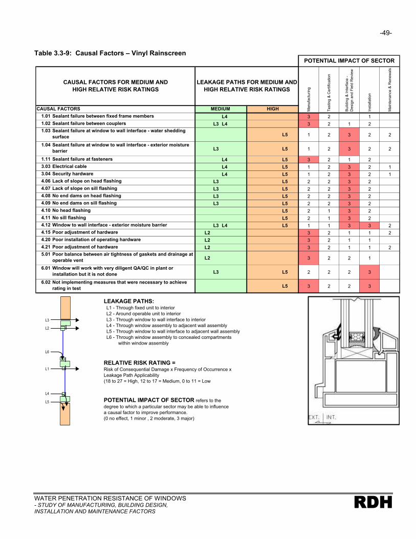
-49-
WATER PENETRATION RESISTANCE OF WINDOWS- STUDY OF MANUFACTURING, BUILDING DESIGN, INSTALLATION AND MAINTENANCE FACTORS
RDH
Table 3.3-9: Causal Factors – Vinyl Rainscreen
1.01 Sealant failure between fixed frame members L4 3 2 1
1.02 Sealant failure between couplers L3 L4 3 2 1 2
1.03 Sealant failure at window to wall interface - water shedding surface L5 1 2 3 2 2
1.04 Sealant failure at window to wall interface - exterior moisture barrier L3 L5 1 2 3 2 2
1.11 Sealant failure at fasteners L4 L5 3 2 1 2
3.03 Electrical cable L4 L5 1 2 3 2 1
3.04 Security hardware L4 L5 1 2 3 2 1
4.06 Lack of slope on head flashing L3 L5 2 2 3 2
4.07 Lack of slope on sill flashing L3 L5 2 2 3 2
4.08 No end dams on head flashing L3 L5 2 2 3 2
4.09 No end dams on sill flashing L3 L5 2 2 3 2
4.10 No head flashing L5 2 1 3 2
4.11 No sill flashing L5 2 1 3 2
4.12 Window to wall interface - exterior moisture barrier L3 L4 L5 1 1 3 3 2
4.15 Poor adjustment of hardware L2 3 2 1 1 2
4.20 Poor installation of operating hardware L2 3 2 1 1
4.21 Poor adjustment of hardware L2 3 2 1 1 2
5.01 Poor balance between air tightness of gaskets and drainage at operable vent L2 3 2 2 1
6.01 Window will work with very diligent QA/QC in plant or installation but it is not done L3 L5 2 2 2 3
6.02 Not implementing measures that were necessary to achieve rating in test L5 3 2 2 3
POTENTIAL IMPACT OF SECTOR
Te
stin
g &
Ce
rtific
atio
n
Main
tenance &
Renew
als
Bu
ildin
g &
In
terf
ace
-
De
sig
n a
nd
Fie
ld R
evie
w
Insta
llatio
n
MEDIUM HIGH Manufa
ctu
ring
LEAKAGE PATHS FOR MEDIUM AND HIGH RELATIVE RISK RATINGS
CAUSAL FACTORS
CAUSAL FACTORS FOR MEDIUM AND HIGH RELATIVE RISK RATINGS
LEAKAGE PATHS: L1 - Through fixed unit to interior
L2 - Around operable unit to interior
L3 - Through window to wall interface to interior
L4 - Through window assembly to adjacent wall assembly
L5 - Through window to wall interface to adjacent wall assembly
L6 - Through window assembly to concealed compartments
within window assembly
L3
L6
L1
L4
L5
L2
RELATIVE RISK RATING = Risk of Consequential Damage x Frequency of Occurrence x
Leakage Path Applicability
(18 to 27 = High, 12 to 17 = Medium, 0 to 11 = Low
POTENTIAL IMPACT OF SECTOR refers to the
degree to which a particular sector may be able to influence
a causal factor to improve performance.
(0 no effect, 1 minor , 2 moderate, 3 major)

-50-
WATER PENETRATION REISTANCE OF WINDOWS- STUDY OF MANUFACTURING, BUILDING DESIGN,
INSTALLATION AND MAINTENANCE FACTORSRDH
Table 3.3-10: Causal Factors – Wood Face Seal
1.01 Sealant failure between fixed frame members L4 3 2 1 1
1.03 Sealant failure at window to wall interface - water shedding surface L5 1 2 3 3 3
1.04 Sealant failure at window to wall interface - exterior moisture barrier L3 L4 L5 1 2 3 3 3
1.05 Sealant failure - cap bead at glazing units L4 2 2 1 2 3
1.10 Sealant failure - brick mold to window frame L5 3 2 1 2 1
1.11 Sealant failure at fasteners L5 2 2 3 3
2.01 Discontinuous glazing tape L4 3 2 1 1 1
2.02 Glazing tape pump out L4 3 2 1 1 1
2.05 Poor fit of gasket L2 3 2 1 1 1
3.04 Security hardware L4 L5 1 2 3 2 1
4.06 Lack of slope on head flashing L3 L5 2 2 3 2
4.07 Lack of slope on sill flashing L5 2 2 3 2
4.08 No end dams on head flashing L3 L5 2 2 3 2
4.09 No end dams on sill flashing L3 L5 2 2 3 2
4.10 No head flashing L5 2 1 3 2
4.11 No sill flashing L5 2 1 3 2
4.12 Window to wall interface - exterior moisture barrier L3 L4 L5 1 1 3 3 3
4.14 Deterioration of finishes L4 3 2 3 1 3
4.16 Deterioration of base material L4 3 2 1 1
4.20 Poor adjustment of hardware L2 3 2 1 1 2
5.01 Poor balance between air tightness of gaskets and drainage at operable vent L2 3 2 2 1
5.03 Use of lower rated window where higher required L4 3 2 3 1
6.01 Window will work with very diligent QA/QC in plant or installation but it is not done L3 L5 3 2 2 3
6.02 Not implementing measures that were necessary to achieve rating in test L5 3 2 2 3
Bu
ildin
g &
In
terf
ace
-
Desig
n a
nd F
ield
Revie
w
Insta
llatio
n
MEDIUM HIGH Ma
nu
factu
rin
g
CAUSAL FACTORS
CAUSAL FACTORS FOR MEDIUM AND HIGH RELATIVE RISK RATINGS
LEAKAGE PATHS FOR MEDIUM AND HIGH RELATIVE RISK RATINGS
POTENTIAL IMPACT OF SECTOR
Te
stin
g &
Ce
rtific
atio
n
Ma
inte
na
nce
& R
en
ew
als
LEAKAGE PATHS: L1 - Through fixed unit to interior
L2 - Around operable unit to interior
L3 - Through window to wall interface to interior
L4 - Through window assembly to adjacent wall assembly
L5 - Through window to wall interface to adjacent wall assembly
L6 - Through window assembly to concealed compartments
within window assembly
L3
L6
L1
L4
L5
L2
RELATIVE RISK RATING = Risk of Consequential Damage x Frequency of Occurrence x
Leakage Path Applicability
(18 to 27 = High, 12 to 17 = Medium, 0 to 11 = Low
POTENTIAL IMPACT OF SECTOR refers to the
degree to which a particular sector may be able to influence
a causal factor to improve performance.
(0 no effect, 1 minor , 2 moderate, 3 major)

-51-
WATER PENETRATION RESISTANCE OF WINDOWS- STUDY OF MANUFACTURING, BUILDING DESIGN, INSTALLATION AND MAINTENANCE FACTORS
RDH
Table 3.3-11: Causal Factors – Wood Rainscreen
1.01 Sealant failure between fixed frame members L4 3 2 1 1
1.03 Sealant failure at window to wall interface - water shedding surface L5 1 2 3 2 3
1.04 Sealant failure at window to wall interface - exterior moisture barrier L3 L4 L5 1 2 3 2 2
1.05 Sealant failure - cap bead at glazing units L4 2 2 1 2 3
1.10 Sealant failure - brick mold to window frame L5 3 2 1 2 1
1.11 Sealant failure at fasteners L5 2 2 3 3
2.01 Discontinuous glazing tape L4 3 2 1 1 1
2.02 Glazing tape pump out L4 3 2 1 1 1
2.05 Poor fit of gasket L2 3 2 1 1 1
3.04 Security hardware L4 L5 1 2 3 2 1
4.06 Lack of slope on head flashing L3 L5 2 2 3 2
4.07 Lack of slope on sill flashing L5 2 2 3 2
4.08 No end dams on head flashing L3 L5 2 2 3 2
4.09 No end dams on sill flashing L3 L5 2 2 3 2
4.10 No head flashing L5 2 1 3 2
4.11 No sill flashing L5 2 1 3 2
4.12 Window to wall interface - exterior moisture barrier L3 L4 L5 1 1 3 3 2
4.14 Deterioration of finishes L4 3 2 3 1 3
4.15 No slope on window frame sill to encourage drainage L2 L4 3 2 1 1
4.16 Deterioration of base material L4 3 2 1 1
4.20 Poor adjustment of hardware L2 3 2 1 1 2
5.01 Poor balance between air tightness of gaskets and drainage at operable vent L2 3 2 2 1
5.03 Use of lower rated window where higher required L4 3 2 3 1
6.01 Window will work with very diligent QA/QC in plant or installation but it is not done L3 L5 2 2 2 3
6.02 Not implementing measures that were necessary to achieve rating in test L5 3 2 2 3
POTENTIAL IMPACT OF SECTOR
Te
stin
g &
Ce
rtific
atio
n
Main
tenance &
Renew
als
Bu
ildin
g &
In
terf
ace
-
Desig
n a
nd F
ield
Revie
w
Insta
llatio
n
MEDIUM HIGH Manufa
ctu
ring
CAUSAL FACTORS
CAUSAL FACTORS FOR MEDIUM AND HIGH RELATIVE RISK RATINGS
LEAKAGE PATHS FOR MEDIUM AND HIGH RELATIVE RISK RATINGS
LEAKAGE PATHS: L1 - Through fixed unit to interior
L2 - Around operable unit to interior
L3 - Through window to wall interface to interior
L4 - Through window assembly to adjacent wall assembly
L5 - Through window to wall interface to adjacent wall assembly
L6 - Through window assembly to concealed compartments
within window assembly
L3
L6
L1
L4
L5
L2
RELATIVE RISK RATING = Risk of Consequential Damage x Frequency of Occurrence x
Leakage Path Applicability
(18 to 27 = High, 12 to 17 = Medium, 0 to 11 = Low
POTENTIAL IMPACT OF SECTOR refers to the
degree to which a particular sector may be able to influence
a causal factor to improve performance.
(0 no effect, 1 minor , 2 moderate, 3 major)

-52-
WATER PENETRATION REISTANCE OF WINDOWS- STUDY OF MANUFACTURING, BUILDING DESIGN,
INSTALLATION AND MAINTENANCE FACTORSRDH
3.4 Industry Sector Response to Assessment of Causal Factors
The following sections summarize the response to the industry sector questionnaire provided in
Appendix C. The tables are organized by industry sector and refer to and provide comments for the
causal factors that their sector was rated as having a significant potential impact. See Tables 3.3-2 to
3.3-11.
Where the responses are very similar for many window types or causal factors they have been
grouped into one summary table.
MANUFACTURING
Representatives of this sector generally agreed with the assessment results. However, they did so in
the context of the building designers having dictated many of the choices that were made. In
particular, the issue of quality control was controversial. While the manufacturing sector viewed
themselves as having opportunities to improve quality control, they also believe that performance of
many installed windows are too sensitive to perfection in manufacturing (it is too hard to have 100% of
the windows meet the performance requirements). They believe that design decisions that impact
exposure conditions, selection of windows, window hardware and back-up sill drainage systems as
being more significant contributors to improving performance, and that they are more readily
achievable.
The manufacturing sector was generally aware of the expected performance and limitations of most
window types in particular exposure conditions. However, their perception was that they can only
supply what is specified, or asked for, otherwise they will be non-competitive. Part of the feedback on
this issue included the observation that while they knew that a particular window may meet the A440
water penetration resistance rating initially, that it was not likely to consistently meet this level of
performance in-service.
Table 3.4-1
Applicable to Window Types:
All window types
Causal Factor(s):
Sealant failure between fixed frame members
Applicable to Leakage Paths:
L1, L4
Since this causal factor has been rated as one that your sector can have a major influence on improving performance, why has action not been taken previously?
• Not possible to make significant improvement to address causal factor

-53-
WATER PENETRATION RESISTANCE OF WINDOWS- STUDY OF MANUFACTURING, BUILDING DESIGN, INSTALLATION AND MAINTENANCE FACTORS
RDH
In your opinion do these causal factors need to be addressed by your industry sector? If no, then why?
• A quality control problem that covers product design, manufacturing, delivery and installation and therefore is difficult to address all issues
What steps do you think need to be taken by your sector to address these causal factors?
• Better quality control during all phases likely to reduce the extent of the problem but not likely to eliminate completely
What impediments exist in being able to implement the steps that you propose?
• Costs to make changes to products prohibitive
• Cost benefit to manufacturers of increased quality control is minimal, will still get call backs
Table 3.4-2
Applicable to Window Types:
AL-1 to 5, VY-1 to 3
Causal Factor(s):
Sealant failure between couplers
Applicable to Leakage Paths:
L3, L4
Since this causal factor has been rated as one that your sector can have a major influence on improving performance, why has action not been taken previously?
• Not possible to make significant improvement to address causal factor
• Not many on each project therefore problems have been isolated
• More dependent on installer than manufacturer
• Not required to be included in A440 tests
In your opinion do these causal factors need to be addressed by your industry sector? If no, then why?
• Yes, through better quality control in manufacturing
• Improve knowledge of installers of system
• Difficult to improve to 100%, therefore a back-up system should be provided
What steps do you think need to be taken by your sector to address these causal factors?
• Improve coupler design
• Provide better information on installation and maintenance procedures
What impediments exist in being able to implement the steps that you propose?
• Costs to make completely effective changes to products prohibitive
• Cost benefit to manufacturers of increased quality control is minimal, will still get call backs and in many cases this will be related to installers work

-54-
WATER PENETRATION REISTANCE OF WINDOWS- STUDY OF MANUFACTURING, BUILDING DESIGN,
INSTALLATION AND MAINTENANCE FACTORSRDH
Table 3.4-3
Applicable to Window Types:
All window types
Causal Factor(s):
Sealant failure at fasteners
Applicable to Leakage Paths:
L4, L5
Since this causal factor has been rated as one that your sector can have a major influence on improving performance, why has action not been taken previously?
• Not possible to cost effectively make significant improvement to address causal factor
In your opinion do these causal factors need to be addressed by your industry sector? If no, then why?
• Yes
What steps do you think need to be taken by your sector to address these causal factors?
• Better quality control during all manufacturing, first to apply sealant in continuous manner and then to keep it dry and protected in service
What impediments exist in being able to implement the steps that you propose?
• Costs to make changes to products prohibitive
• Cost benefit to manufacturers of increased quality control is minimal, will still get call backs
Table 3.4-4
Applicable to Window Types:
AL-1, VY-1
Causal Factor(s):
Discontinuous glazing tape
Applicable to Leakage Paths:
L1, L4
Since this causal factor has been rated as one that your sector can have a major influence on improving performance, why has action not been taken previously?
• Ongoing quality control issue
In your opinion do these causal factors need to be addressed by your industry sector? If no, then why?
• Yes
What steps do you think need to be taken by your sector to address these causal factors?
• Better quality control during manufacturing
What impediments exist in being able to implement the steps that you propose?
• None

-55-
WATER PENETRATION RESISTANCE OF WINDOWS- STUDY OF MANUFACTURING, BUILDING DESIGN, INSTALLATION AND MAINTENANCE FACTORS
RDH
Table 3.4-5
Applicable to Window Types:
AL-1 to 4, VY-1, VY-2
Causal Factor(s):
Poor seal between vent adapter and frame
Applicable to Leakage Paths:
L2, L4
Since this causal factor has been rated as one that your sector can have a major influence on improving performance, why has action not been taken previously?
• Ongoing quality control issue
In your opinion do these causal factors need to be addressed by your industry sector? If no, then why?
• Yes
What steps do you think need to be taken by your sector to address these causal factors?
• Better quality control during manufacturing
What impediments exist in being able to implement the steps that you propose?
• None
Table 3.4-6
Applicable to Window Types:
AL-2 to 4
Causal Factor(s):
Screw spline blocking drainage path
No slope on window frame sill to encourage drainage Applicable to Leakage Paths:
L4
Since this causal factor has been rated as one that your sector can have a major influence on improving performance, why has action not been taken previously?
• Process to make change is too costly due to new dies and inventory
In your opinion do these causal factors need to be addressed by your industry sector? If no, then why?
• Yes
What steps do you think need to be taken by your sector to address these causal factors?
• Change in design required with new dies
What impediments exist in being able to implement the steps that you propose?
• Costs to make changes to products prohibitive
• Cost benefit to manufacturers of changes is minimal, call backs appear to be more related to other issues and industry sectors

-56-
WATER PENETRATION REISTANCE OF WINDOWS- STUDY OF MANUFACTURING, BUILDING DESIGN,
INSTALLATION AND MAINTENANCE FACTORSRDH
Table 3.4-7
Applicable to Window Types:
All types
Causal Factor(s):
Poor adjustment of hardware
Applicable to Leakage Paths:
L2
Since this causal factor has been rated as one that your sector can have a major influence on improving performance, why has action not been taken previously?
• Not always a problem, depends on design, size of operable units
In your opinion do these causal factors need to be addressed by your industry sector? If no, then why?
• Yes, but other sectors need to be involved
What steps do you think need to be taken by your sector to address these causal factors?
• Better hardware is available but must be specified. Poorer quality hardware will require maintenance and renewals more frequently.
What impediments exist in being able to implement the steps that you propose?
• Costs to use better hardware
Table 3.4-8
Applicable to Window Types:
AL-1, VY-1 primarily
Causal Factor(s):
Glazing tape pump out (butyl) or plastic deformation (foam)
Applicable to Leakage Paths:
L1, L4
Since this causal factor has been rated as one that your sector can have a major influence on improving performance, why has action not been taken previously?
• Ongoing balance between better tape or gasket, maintenance requirements and cost
In your opinion do these causal factors need to be addressed by your industry sector? If no, then why?
• Yes
What steps do you think need to be taken by your sector to address these causal factors?
• Specify better quality butyl and foam tapes
What impediments exist in being able to implement the steps that you propose?
• None

-57-
WATER PENETRATION RESISTANCE OF WINDOWS- STUDY OF MANUFACTURING, BUILDING DESIGN, INSTALLATION AND MAINTENANCE FACTORS
RDH
Table 3.4-9
Applicable to Window Types:
AL-1 to 3, VY-1 & 2, W-1, W-2
Causal Factor(s):
Use of lower rated window (A440 water penetration rating) where higher required
Applicable to Leakage Paths:
L1, L2, L4
Since this causal factor has been rated as one that your sector can have a major influence on improving performance, why has action not been taken previously?
• We provide what is specified
In your opinion do these causal factors need to be addressed by your industry sector? If no, then why?
• Yes, since we can provide higher rated window assembly, but choice of window is not primarily related to manufacturing sector
What steps do you think need to be taken by your sector to address these causal factors?
• Advise designers/owners on appropriateness of a window for a particular application
• Work with designers to establish appropriate windows exposure conditions
What impediments exist in being able to implement the steps that you propose?
• Choice of higher rated window usually means more expensive window
• Not always involved prior to bids being invited
• Risk losing sales if advise that use in particular application is not appropriate
TESTING & CERTIFICATION
At present, testing and certification need to be considered as two distinct aspects of this sector. On
the one hand water penetration testing standards and procedures exist and are undertaken on a
regular basis. On the other hand there is no generally accepted or mandated certification standard or
process in place for window manufacturing or installation. Note that the report on the companion
study addresses some of the testing and certification issues in greater detail.
The testing component of this sector generally saw themselves as fulfilling a useful role in
identification of the need to address causal factors. For example, testing facilitates the focusing of
efforts on particular leakage paths and causal factors.
However, once an issue had been identified this sector viewed other sectors as taking the lead in
terms of addressing issues such as:
§ Change in manufacturing process
§ Change in design of interface detail
§ Correction of defect in installation
§ The need to replace aging sealant

-58-
WATER PENETRATION REISTANCE OF WINDOWS- STUDY OF MANUFACTURING, BUILDING DESIGN,
INSTALLATION AND MAINTENANCE FACTORSRDH
As a result of the perception that other sectors must take the lead in implementing changes there
were no ‘major impact’ ratings given to the testing and certification sector.
If a certification process had been established then some of the ratings for Quality Assurance/Quality
Control causal factors may have received major impact ratings, and therefore it would be possible for
this sector to have greater influence on performance improvements.
BUILDING & INTERFACE DESIGN AND FIELD REVIEW
This sector readily acknowledges its role and potential impact in addressing many of the causal
factors. It was also noted that the focus on building envelope performance issues has evolved with
the advent of many new materials, components, wall assemblies, and as a result of the lack of
qualified trades etc. Historically, many of the detailing issues had been left to the general contractor
and the trades to be undertaken in accordance with good practice. This sector’s perception was that it
is the many new materials, components and assemblies when combined with the lack of skilled trades
that has dictated the need for their greater involvement.
Table 3.4-10
Applicable to Window Types:
All types
Causal Factor(s):
Sealant failure at window to wall interface - water shedding surface
Sealant failure at window to wall interface - exterior moisture barrier
Window to wall interface – exterior moisture barrier
Applicable to Leakage Paths:
L3, L4, L5
Since this causal factor has been rated as one that your sector can have a major influence on improving performance, why has action not been taken previously?
• Not aware that sector was responsible for addressing this issue
• Not aware that this causal factor was an issue
In your opinion do these causal factors need to be addressed by your industry sector? If no, then why?
• Yes
What steps do you think need to be taken by your sector to address these causal factors?
• Develop better selection process/criteria for appropriate windows accounting for localized exposure conditions
• Develop better understanding of function and continuity of critical barriers
• Improve detailing of the window to wall interface
• Greater attention to the installation details during field review of construction
• Develop better understanding of material properties, compatibilities etc.
• Undertake more mock-ups and field testing to confirm details and performance of installed window

-59-
WATER PENETRATION RESISTANCE OF WINDOWS- STUDY OF MANUFACTURING, BUILDING DESIGN, INSTALLATION AND MAINTENANCE FACTORS
RDH
What impediments exist in being able to implement the steps that you propose?
• Lack of guidance on selection of appropriate windows, detailing and specification criteria for windows
• Lack of familiarity with window performance attributes
• New products on the market all the time, unable to determine acceptability
• Inadequate fees for undertaking level of service required
Table 3.4-11
Applicable to Window Types:
All types
Causal Factor(s):
Electrical cable
Security hardware Applicable to Leakage Paths:
L4, L5
Since this causal factor has been rated as one that your sector can have a major influence on improving performance, why has action not been taken previously?
• Not aware that this causal factor was an issue for this sector. Security devices and electrical cables not usually within scope of designer, and often placed after window installation is complete.
In your opinion do these causal factors need to be addressed by your industry sector? If no, then why?
• Yes
What steps do you think need to be taken by your sector to address these causal factors?
• Needs to be included in design scope of work; for larger projects this will be a coordination issue with other members of the design team
• Design all penetrations so that they penetrate the exterior moisture barrier at locations that are least exposed to moisture
• Greater attention to the work of trades unrelated to the window installation during field review.Discuss issue with other trade contractors.
What impediments exist in being able to implement the steps that you propose?
• Cost, greater level of effort required for coordination and possibly field review
• Often cables etc. installed after building envelope field review is complete

-60-
WATER PENETRATION REISTANCE OF WINDOWS- STUDY OF MANUFACTURING, BUILDING DESIGN,
INSTALLATION AND MAINTENANCE FACTORSRDH
Table 3.4-12
Applicable to Window Types:
All types
Causal Factor(s):
Lack of slope on head flashing
Lack of slope on sill flashing
No end dams on head flashing
No end dams on sill flashing
No head flashing
No sill flashing
Applicable to Leakage Paths:
L3, L5
Since this causal factor has been rated as one that your sector can have a major influence on improving performance, why has action not been taken previously?
• General lack of appreciation of the need for flashing, and sensitivity of the performance to the details of flashing
• Misconception that windows may not require flashing to perform
In your opinion do these causal factors need to be addressed by your industry sector? If no, then why?
• Yes
What steps do you think need to be taken by your sector to address these causal factors?
• Improve extent and nature of detailing for flashing
• Review of mock-ups of flashing and window interface details
What impediments exist in being able to implement the steps that you propose?
• None
INSTALLATION
The most significant and consistent feedback received from this sector was the fact that while they are
the focal point for the final product, they are installing a product manufactured by another party in
accordance with instructions (drawings and specifications) from another party. Their impression is
that they have limited capacity for initiating change. The best installation cannot overcome poor
window to wall interface details, an inappropriate choice of window, and/or a defective window.

-61-
WATER PENETRATION RESISTANCE OF WINDOWS- STUDY OF MANUFACTURING, BUILDING DESIGN, INSTALLATION AND MAINTENANCE FACTORS
RDH
Table 3.4-13
Applicable to Window Types:
AL-1, VY-1, W-1
Causal Factor(s):
Sealant failure at window to wall interface - water shedding surface
Sealant failure at window to wall interface - exterior moisture barrier
Applicable to Leakage Paths:
L3, L5
Since this causal factor has been rated as one that your sector can have a major influence on improving performance, why has action not been taken previously?
• Sector not in a position to be able to change design that calls for interface detail that is reliant on sealant in exposed location to resist moisture ingress
In your opinion do these causal factors need to be addressed by your industry sector? If no, then why?
• No, because in most cases the key decisions are made in the design phase
• Once the design decisions have been made installation is responsible initially but in most cases maintenance of the seal (in a face seal application) is critical to its long term success
What steps do you think need to be taken by your sector to address these causal factors?
• Better education and trade training regarding various barriers and their lines of continuity so that appropriate questions regarding design can be raised
• Specific installation instructions and guidance from sealant manufacturers
• Greater use of mock-ups to better identify any discontinuities or installation problems
What impediments exist in being able to implement the steps that you propose?
• Limited availability of educational guidance for trades
• Many manufacturers do not have qualified personnel
• Many general contractors of construction managers do not account for mock-ups and adjustments in the critical paths of their schedules
Table 3.4-14
Applicable to Window Types:
All window types
Causal Factor(s):
Window will work with very diligent QA/QC during installation but is not done
Applicable to Leakage Paths:
L3, L5
Since this causal factor has been rated as one that your sector can have a major influence on improving performance, why has action not been taken previously?
• Process to make change is too costly. Time lost checking work is not usually specified or built into contract.
In your opinion do these causal factors need to be addressed by your industry sector? If no, then why?
• Yes, a quality control person (foreman or lead hand) should review the product for damage.Each step in the installation should be checked and approved.
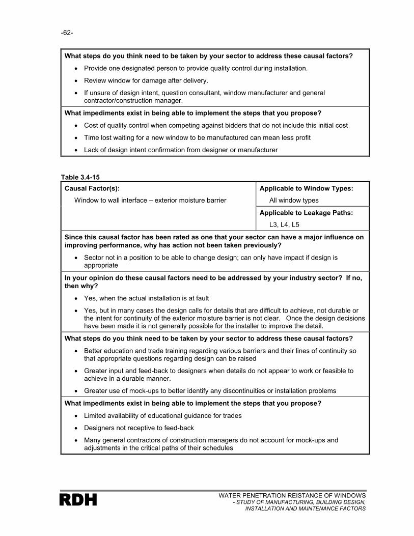
-62-
WATER PENETRATION REISTANCE OF WINDOWS- STUDY OF MANUFACTURING, BUILDING DESIGN,
INSTALLATION AND MAINTENANCE FACTORSRDH
What steps do you think need to be taken by your sector to address these causal factors?
• Provide one designated person to provide quality control during installation.
• Review window for damage after delivery.
• If unsure of design intent, question consultant, window manufacturer and general contractor/construction manager.
What impediments exist in being able to implement the steps that you propose?
• Cost of quality control when competing against bidders that do not include this initial cost
• Time lost waiting for a new window to be manufactured can mean less profit
• Lack of design intent confirmation from designer or manufacturer
Table 3.4-15
Applicable to Window Types:
All window types
Causal Factor(s):
Window to wall interface – exterior moisture barrier
Applicable to Leakage Paths:
L3, L4, L5
Since this causal factor has been rated as one that your sector can have a major influence on improving performance, why has action not been taken previously?
• Sector not in a position to be able to change design; can only have impact if design is appropriate
In your opinion do these causal factors need to be addressed by your industry sector? If no, then why?
• Yes, when the actual installation is at fault
• Yes, but in many cases the design calls for details that are difficult to achieve, not durable or the intent for continuity of the exterior moisture barrier is not clear. Once the design decisions have been made it is not generally possible for the installer to improve the detail.
What steps do you think need to be taken by your sector to address these causal factors?
• Better education and trade training regarding various barriers and their lines of continuity so that appropriate questions regarding design can be raised
• Greater input and feed-back to designers when details do not appear to work or feasible to achieve in a durable manner.
• Greater use of mock-ups to better identify any discontinuities or installation problems
What impediments exist in being able to implement the steps that you propose?
• Limited availability of educational guidance for trades
• Designers not receptive to feed-back
• Many general contractors of construction managers do not account for mock-ups and adjustments in the critical paths of their schedules

-63-
WATER PENETRATION RESISTANCE OF WINDOWS- STUDY OF MANUFACTURING, BUILDING DESIGN, INSTALLATION AND MAINTENANCE FACTORS
RDH
MAINTENANCE AND RENEWALS
This sector was the most difficult to assess. A key issue is the general lack of readily available
information regarding service life expectations of windows and related materials for particular
applications. A second key issue is related to what can be considered reasonable maintenance and
renewals activity, and in what time frame or frequency these activities can be considered reasonable.
Finally there is a general failure of any sector to provide maintenance and renewals guidance in the
form of a plan. The result was that representatives of this sector generally found that they did not
know what was required of them for maintenance and renewals, and that they were generally unaware
of the sensitivity of some aspects of the installed window to overall performance (for example, the
critical need to maintain interface sealant and glazing tapes in face seal applications).
The five year context for the evaluation of the windows dictated that there were few ‘high impact’
ratings given to this sector. Aside from the possible need to renew finishes on wood windows,
adjustment of hardware for operable windows, and sealant failures there were no maintenance or
renewal activities that could be considered medium or high relative risk of contributing to water
penetration problems. In identifying these three issues it was noted that it was likely a poor window
selection, or poor interface design that resulted in the need for maintenance activity within the first five
years being critical to the window’s water penetration performance.
3.5 Comparison With Test Reports
As part of the companion study (Water Penetration Resistance of Windows – Codes, Standards,
Testing, Certification and Harmonization) the results of a large number (240) of lab and field tests
were assembled.
The test results do not provide a representation of the performance of the general population of
windows, or of particular window types. The tests are an arbitrary sampling, intended to provide
information related to leakage paths and causal factors so that conclusions may be reached with
respect to the effectiveness of current test standards.
For the purposes of the current study only a brief overview of the results are reported to facilitate
verification and comparison with the assessment results. A more detailed analysis and discussion of
the test results forms part of the companion study.
Table 3.5-1 summarizes the total number of field and laboratory tests along with associated test
protocol that was used in the testing.

-64-
WATER PENETRATION REISTANCE OF WINDOWS- STUDY OF MANUFACTURING, BUILDING DESIGN,
INSTALLATION AND MAINTENANCE FACTORSRDH
Table 3.5-1: Summary Test Reports
Test Report Type Test Protocol Total Test Reports
Laboratory ASTM E547 113
Field ASTM E1105 127
Table 3.5-2 summarizes the results of the laboratory tests for all window types. The numbers
represent the total number of occurrences of particular leakage paths or causal factors. Pass results
are not reported.
Table 3.5-2: Summary of Laboratory Test Results (All window types together)
LEAKAGE PATHS
Leakage Paths Total
L1 - Through fixed unit to interior 3
L2 - Around operable unit to interior 75
L3 - Through window to wall interface to interior 0
L4 - Through window assembly to adjacent wall assembly
0
L5 - Through window to wall assembly interface to adjacent wall assembly
0
L6 - Through window assembly to concealed compartments within window assembly
1
CAUSAL FACTORS
Specific Causal Factors Totals
1.01 Sealant failure between fixed frame members 1
1.02 Sealant failure between couplers 1
1.05 Sealant failure – heal bead to glazing units 10
1.12 Sealant failure at fasteners 1
5.01 Poor balance between air tightness of gaskets and drainage at operable vents 31
5.04 Limited by sill height 35
L3
L6
L1
L4
L5
L2

-65-
WATER PENETRATION RESISTANCE OF WINDOWS- STUDY OF MANUFACTURING, BUILDING DESIGN, INSTALLATION AND MAINTENANCE FACTORS
RDH
Table 3.5-3 summarizes the results of the field tests for all window types. Again the numbers
represent the total number of occurrences of particular leakage paths or causal factors and pass
results are not reported. Note also that many of the field tests were conducted on windows that
included sub-sill drainage capability and therefore eliminated (or greatly reduced) the probability of
occurrence for the L4 and L5 leakage paths. The results for these two leakage paths are therefore
likely to be understated in the context of the assessment criteria for this study.
Table 3.5-3: Summary of Field Test Results (All window types together)
LEAKAGE PATHS
Leakage Paths Total
L1 - Through fixed unit to interior 68
L2 - Around operable unit to interior 61
L3 - Through window to wall interface to interior 15
L4 - Through window assembly to adjacent wall assembly
17
L5 - Through window to wall assembly interface to adjacent wall assembly
38
L6 - Through window assembly to concealed compartments within window assembly
16
CAUSAL FACTORS
Specific Causal Factors Totals
1.01 Sealant failure between fixed frame members 48
1.02 Sealant failure between couplers 1
1.03 Sealant failure at window to wall interface – exterior moisture barrier 12
1.04 Cap bead to glazing units 4
1.05 Sealant failure at cap bead to glazing unit 2
1.06 Sealant failure - heal bead to glazing units 4
1.07 Sealant failure - backpan to frame 4
1.08 Sealant failure - head flashing segmented joint 7
2.01 Discontinuous glazing tape 13
2.02 Glazing tape pump out 3
L3
L6
L1
L4
L5
L2
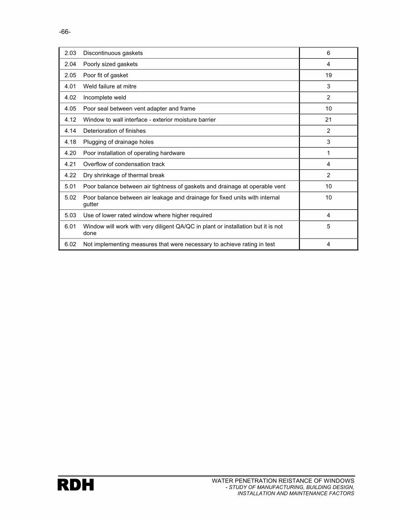
-66-
WATER PENETRATION REISTANCE OF WINDOWS- STUDY OF MANUFACTURING, BUILDING DESIGN,
INSTALLATION AND MAINTENANCE FACTORSRDH
2.03 Discontinuous gaskets 6
2.04 Poorly sized gaskets 4
2.05 Poor fit of gasket 19
4.01 Weld failure at mitre 3
4.02 Incomplete weld 2
4.05 Poor seal between vent adapter and frame 10
4.12 Window to wall interface - exterior moisture barrier 21
4.14 Deterioration of finishes 2
4.18 Plugging of drainage holes 3
4.20 Poor installation of operating hardware 1
4.21 Overflow of condensation track 4
4.22 Dry shrinkage of thermal break 2
5.01 Poor balance between air tightness of gaskets and drainage at operable vent 10
5.02 Poor balance between air leakage and drainage for fixed units with internal gutter
10
5.03 Use of lower rated window where higher required 4
6.01 Window will work with very diligent QA/QC in plant or installation but it is not done
5
6.02 Not implementing measures that were necessary to achieve rating in test 4

-67-
WATER PENETRATION RESISTANCE OF WINDOWS- STUDY OF MANUFACTURING, BUILDING DESIGN, INSTALLATION AND MAINTENANCE FACTORS
RDH
4. CONCLUSIONS
4.1 Introduction
The study provides a comprehensive list of factors that may contribute to water penetration problems
associated with windows. This list and the associated descriptions and visual examples should form a
useful reference tool both for diagnosing the cause of problems when they occur and as a checklist
for avoiding problems.
Although not established as one of the specific goals for the study, the exercise of classifying the
window types by base frame material and water penetration control strategy was a valuable outcome
of the study in itself. It establishes a starting point (benchmark) for the comparison and classification
of windows for the evaluation of their potential for controlling water penetration. A rainscreen window
can generally be expected to provide better and more durable water penetration performance than a
face seal window in conditions where the window is regularly exposed to wind driven rain.
Another aspect of the study that was not anticipated as a specific outcome but may be valuable is the
establishment of the concept of four critical barriers and the application of these barriers in
understanding the performance of windows and window to wall interfaces.
It should be re-emphasized that conclusions drawn from this study cannot be used to evaluate relative
water penetration control performance of the various window types. More specific information is
needed regarding the exposure conditions (wind driven rain, and localized building features that
control exposure) before windows can be evaluated with respect to water penetration performance.
All windows will perform acceptably for some length of time in certain exposure conditions.
The reference to acceptable length of time highlights another factor that was not assessed as part of
this study. The durability of a particular installed window with respect to water penetration is not
considered except in the context of impact of maintenance and renewals on causal factors. The issue
of durability is clearly relevant in the selection and detailing of the installed window since it impacts the
time until maintenance and renewals are required, as well as the nature and ease of undertaking that
maintenance and renewal activity.

-68-
WATER PENETRATION RESISTANCE OF WINDOWS- STUDY OF MANUFACTURING, BUILDING DESIGN,
INSTALLATION AND MAINTENANCE FACTORSRDH
4.2 Specific Conclusions
The following provides specific conclusions that emerge from the analysis of the data. In some
instances these conclusions are interrelated, or could have been listed in more than category.
Leakage Paths
1. The dominant leakage path based on frequency of occurrence is clearly L5 (through window to
wall assembly interface to adjacent wall assembly). Based on an assessment of risk of
consequential damage both L4 (through window to adjacent wall assembly) and L5 can be
considered to be high risk. Relatively minor variation exists between window types with respect
to leakage paths.
Causal Factors
2. A wide range of causal factors were found to contribute to leakage activity. It is not possible to
reach conclusions related to the prevalence of certain causal factors since they can only be
considered in the context of particular leakage paths. Therefore causal factors associated with
the dominant leakage paths (L4 & L5) inherently will feature more prominently in the summary
table provided in Chapter 3.
Relative Risk Ratings
3. The results of the relative risk rating scale highlights the need to focus all sectors on
improvements to the window to wall interface.
General Industry Sector Potential Impacts
4. The two industry sectors that appear to have the most significant opportunities to impact
positively on the performance of windows are the Manufacturing sector, and the Building &
Interface Design and Field Review sector. This finding reflects the fundamental influence that the
window as a manufactured assembly has on performance, as well as the influence of the
Building & Interface Design and Field Review sector on the dominant leakage paths associated
with the window to wall interface.
5. There is no explicit consideration of performance durability by many sectors that guides their
processes or decision making. There are no requirements with respect to service life
expectations presented to the building and interface designers either through codes or by the
owners of the building. In addition, this sector appears to rely solely on the B ratings from the
A440 standard as the performance measurement. The B ratings in turn do not reflect any

-69-
WATER PENETRATION RESISTANCE OF WINDOWS- STUDY OF MANUFACTURING, BUILDING DESIGN, INSTALLATION AND MAINTENANCE FACTORS
RDH
consideration for the time frame for which a window should maintain the B rating. For example, it
is not the initial water penetration performance that differentiates between the performance of
face seal and rainscreen window types. Rather, it is the more durable service life expectations of
rainscreen window that make it ‘better‘ than a face seal window. There are often no requirements
in the drawings and specifications reflecting service life considerations, most significantly with
respect to choice of materials, exterior moisture control strategy and maintenance and renewals
expectations.
6. Comments from several sectors indicated that they could differentiate between performance
expectations of various window types. In particular, the Manufacturing sector indicated that they
would prefer to provide higher performing more durable windows but were not always being
asked to do so. From a designer perspective it is clear that acceptable performance can be
provided with different combinations of initial design, choice of window and future maintenance
and renewal activities and costs. The selection of low initial cost often drives the choices made.
Mandating good windows, or good choices for particular exposure conditions would even the
playing field and establish a higher benchmark of performance and durability.
Manufacturing
7. Quality control is the focal point for improvement in this sector impacting a range of causal
factors.
8. While acknowledging the need to improve some aspects of quality control, representatives from
this sector also note that it will not be possible to achieve perfection in manufacturing, nor is it
possible to make significant improvements to many of the window products. Accepting these
statements suggests that despite the results of the assessment, other sectors and focuses may
have a greater impact on improving performance. Therefore, although the causal factors
identified can best be addressed by this sector, they may not be the most effective solution to the
leakage problem. For example, improving quality control procedures so that leakage through
mitred joints is eliminated may not be as effective a solution to the problem as providing sub-sill
drainage capability.
9. Lower rated windows are being used in exposure conditions beyond their capability for durable
performance. Although manufacturers seem aware that this is occurring and can provide more
appropriate windows, this is not always occurring. They are however, providing windows that
meet the specified B ratings. This suggests that either the B ratings are not appropriate
indicators of durable in-service performance, or the specification for the windows needs to
include additional performance criteria.

-70-
WATER PENETRATION RESISTANCE OF WINDOWS- STUDY OF MANUFACTURING, BUILDING DESIGN,
INSTALLATION AND MAINTENANCE FACTORSRDH
Testing & Certification
10. The A440 B rating performance criteria may be largely successful in identifying the leakage paths
that it was originally intended to address as a manufacturing quality control standard but it does
not address the current dominant leakage paths that are associated with the installed windows.
Table 4.1 repeats some of the information contained in Table 3.2 and adds a column indicating
the applicability of the A440 specified test procedure. It is clear that the leakage paths of most
concern are not addressed or inadequately addressed by the current standard.
Table 4.1: Applicability of the A440 Standard to Leakage Paths
Leakage Paths Risk of ConsequentialDamage Rating
Applicability of A440 Testing to Leakage Path
L1 - Through fixed unit to interior Moderate Good
L2 - Around operable unit to interior
Moderate Good
L3 - Through window to wall interface to interior
Moderate Never
L4 - Through window assembly to adjacent wall assembly
High Sometimes*
L5 - Through window to wall assembly interface to adjacent wall assembly
High Never
L6 - Through window assembly to concealed compartments within window assembly
Minor Good
* Depends on where window frame is attached to test frame
11. The A440 standard utilizes historical rainfall and wind records to establish B ratings for particular
municipalities. It does not appropriately consider micro climate effects such as building form,
overhangs, or local terrain effects. These issues in many instances can have a more significant
impact on water penetration performance than the local climate since they determine how much
wind driven rain impacts on the face of the building.
The water penetration B ratings are significant in the context of relatively infrequent wind driven
rain, whereas micro climate factors are significant in every rainfall event.
L3
L6
L1
L4
L5
L2

-71-
WATER PENETRATION RESISTANCE OF WINDOWS- STUDY OF MANUFACTURING, BUILDING DESIGN, INSTALLATION AND MAINTENANCE FACTORS
RDH
12. There is no certification system in place that addresses the water penetration performance of
installed windows. If a program did exist it is believed that it could have a positive impact on
performance.
Building & Interface Design and Field Review
13. This sector has most potential impact on the dominant leakage paths and associated causal
factors (L5 - through window to wall assembly interface to adjacent wall assembly, L4 - through
window to adjacent wall assembly).
14. The assumption of lack of sub-sill drainage used in the assessment process impacts the
conclusions significantly. Lack of sub-sill drainage means that moisture from a variety of leakage
paths and causal factors will enter the adjacent wall assembly potentially causing damage. This
suggests that its addition to interface design would improve water penetration performance of
installed windows.
15. All window types indicate high risk of water penetration due to causal factors related to window to
wall interface design. Therefore, leakage paths L3 and L5 are independent of window type.
16. Many new materials, components, assemblies and the lack of skilled trades have generated a
need for this sector to be more involved in interface design and field review.
Installation
17. The installation sector has little control over many of the issues that impact the performance of
the installed window. In larger multi-unit residential buildings a design team is involved in the
project. The installer typically installs a window manufactured by others in accordance with
interface details provided by others. The focus therefore is on trade training, improved quality
control and effective identification of manufacturing and design issues for resolution in
conjunction with other sectors. In smaller Part 9 buildings, the role of the installer is actually
expanded since they usually determine the details to be used. The installer may need to have
greater understanding of the design strategy and details of water penetration for these smaller
buildings, further emphasizing the need for trade training.
Maintenance & Renewals
18. Maintenance and renewals plans are not generally being provided by those in the best position to
create an effective plan (Manufacturing and Building & Interface Design and Field Review).

-72-
WATER PENETRATION RESISTANCE OF WINDOWS- STUDY OF MANUFACTURING, BUILDING DESIGN,
INSTALLATION AND MAINTENANCE FACTORSRDH
19. The installed window assembly for some applications (face seal in medium or high exposure
conditions) is too sensitive to maintenance activity. The nature of the required maintenance and
the time frame in which it is required is unreasonable.
20. Those responsible for undertaking maintenance and renewals activities are not aware of the
strategy and details for water penetration control and therefore are not aware of the sensitivity of
performance to some maintenance and renewal activity. An example of this would be the need
for cap beading of face sealed windows when used in exposed conditions.

-73-
WATER PENETRATION RESISTANCE OF WINDOWS- STUDY OF MANUFACTURING, BUILDING DESIGN, INSTALLATION AND MAINTENANCE FACTORS
RDH
5. RECOMMENDATIONS
The results of this study indicate some clear focal points in the improvement of water penetration
performance of windows. All sectors have significant opportunities to be involved in the activities
recommended below. Some of the recommendations require relatively subtle changes in current
processes while others represent fundamental changes in direction.
General
1. Consideration of micro exposure conditions must become an explicit consideration of the
establishment of exposure classification. This will facilitate a window selection process that
reflects frequency and duration of wetting as well as wind driven rain pressure. Micro exposure
considerations include local terrain, building form and overhang protection. A discussion and
suggested methodology for consideration of micro exposure factors is outlined in the Best
Practice Guide – Wood Frame Envelopes in the Coastal Climate of British Columbia.
2. Performance expectations for water penetration resistance based on a rational exposure
classification system, including the durability of that performance level, needs to be mandated.
This will even the playing field and facilitate manufacturers and building designers using
technology that already exists to provide effective acceptable water penetration performance.
The inclusion of durability in this mandate will also facilitate the differentiation of variations in
performance between water penetration control strategies (face seal, concealed barrier and
rainscreen window types)
3. A ‘Best Practice Guide’ for windows should be developed that integrates not only the
recommendations developed in this report with respect to effective water penetration control, but
all other performance issues associated with window specification, selection, interface design and
maintenance and renewals. This document should consider the inclusion of a ‘commissioning’
guide that helps to ensure effective decision making and verification of performance throughout
the service life of a window.
4. Maintenance and renewals plans should be developed on a building specific basis by those with
appropriate knowledge to prepare the plan; believed to be the Manufacturing sector in
combination with Building & Interface Design and Field Review sector. These plans should
describe the design strategy, function of components and materials, in addition to the frequency,
procedures and materials to be used in undertaking the maintenance and renewals activities.

-74-
WATER PENETRATION RESISTANCE OF WINDOWS- STUDY OF MANUFACTURING, BUILDING DESIGN,
INSTALLATION AND MAINTENANCE FACTORSRDH
Manufacturing
5. The manufacturing sector has a general need to increase focus on quality control. This includes
issues related to product design, and assembly of window components. This may be achieved
partly through increased quality assurance efforts however, consistency in performance may
require retooling for some plant operations. The specific needs must evaluated on a case by case
basis.
6. As part of an improved focus on quality control it is recommended that all manufacturing facilities
include an in-plant water penetration testing facility. This not only provides direct improvement in
quality control efforts due the on-going testing, but it provides a useful educational tool for plant
workers. They can see where windows leak and the causal factors that have resulted in the leak
first hand.
7. Manufacturers have to focus on the design of entire installed window. This includes couplers, and
the interface with the perimeter building walls. This will facilitate greater consistency in achieving
continuity of the critical barriers at interfaces and could make interface construction easier for the
installers. The production of shop drawings that reflect the window to wall interface details should
form part of this increased focus on the installed window.
8. Manufacturers need to take a more active role in the installation of their product. This could be
done either by selling windows as a supply and install product, or by training and approving
installers that use their product. This will also improve the feedback from installers to the
manufacturers so that a cycle of continuous improvement can be established.
9. The Manufacturing sector must provide realistic maintenance and renewals recommendations for
their products for the intended service life of the product. This will require collaboration with the
Building & Interface Design sector since they will need to provide similar guidance with respect to
the wall to window interface.
Testing & Certification
10. A water penetration testing protocol needs to be developed and mandated for the installed window
that also reflects building specific conditions. This could be done as part of the installation section
of current A440 standard series (A440.4).
11. The A440 assessment of exposure conditions for calculation of B ratings should be modified to
include micro climate issues as discussed in Recommendation No. 1.

-75-
WATER PENETRATION RESISTANCE OF WINDOWS- STUDY OF MANUFACTURING, BUILDING DESIGN, INSTALLATION AND MAINTENANCE FACTORS
RDH
12. The creation of a mandated or generally accepted certification protocol, could have an impact on
quality control issues. This program should include a requirement for random inspection and
testing. Certification has the potential to close the gap between a one time pass of a B rating test
and consistent ongoing performance.
Building & Interface Design and Field Review
13. There is a need for this sector to increase their focus on interface detailing, considering continuity
of all of the critical barriers, as well as durability, and maintenance and renewals issues.
14. A key component of this focus on interface detailing is to provide some redundancy in the installed
assembly to allow for the understanding that it is not possible to achieve perfection in the
manufacturing and installation process. Sub-sill drainage should be provided for all windows
except those that are located in a ‘no exposure’ environment. The specifics of the detail should
reflect the actual exposure conditions. For example, a sloped sub-sill may only be necessary in
medium and high exposure situations. This is the single most significant recommendation in
achieving improved performance of installed windows and can be achieved at relatively low cost
to the industry.
15. Windows should be specified and selected based on consideration of micro and macro exposure
conditions. This will be easier to put into practice if mandated as proposed in Recommendation
No. 11.
16. Specifying field performance verification for each building project will assist in identifying
anomalies in the construction and further reduce the frequency of in-service performance
problems.
Installation
17. Although this sector rarely has control of the key aspects of the manufacturing or interface design
there is a need for it to focus quality control issues. This will primarily involve inspection of
windows as they arrive on site to ensure that they meet the project requirements, a greater focus
on the quality of installation, and questioning uncertainties in the windows or in the detailing.
18. Greater trade training should be made available and possibly mandated. The programs should
clearly include the wide range of specific window installation techniques, but should also include
instruction regarding design concepts and intent.

-76-
WATER PENETRATION RESISTANCE OF WINDOWS- STUDY OF MANUFACTURING, BUILDING DESIGN,
INSTALLATION AND MAINTENANCE FACTORSRDH
Maintenance & Renewals
19. The creation of a realistic maintenance and renewals plan could have an impact on in-service
performance of windows. This sector, which is responsible for implementing the plan, must
ensure that all maintenance and renewals recommendations are followed and that the plan is
updated and modified as knowledge of the actual in-service performance of the windows
becomes known.
RDH BUILDING ENGINEERING LIMITED
WATER PENETRATION RESISTANCE OF WINDOWS- STUDY OF MANUFACTURING, BUILDING DESIGN, INSTALLATION AND MAINTENANCE FACTORS
RDH
REFERENCES
1. Survey of Building Envelope Failures in the Coastal Climate of British Columbia, Canada Mortgage and Housing Corporation, 1996.
2. Study of Wall Moisture Problems in Alberta Dwellings, Canada Mortgage and Housing Corporation, 1999
3. Study of High-Rise Envelope Performance, Canada Mortgage and Housing Corporation, 2001
4. Glazing Design, Canadian Building Digest No. 55, Division of Building Research, National Research Council, 1964
5. Rain Leakage of Residential Windows in the Lower Mainland of British Columbia, Building Practice Note No. 42, Division of Building Research, National Research Council of Canada, 1984.
6. Rain Leakage in Wood Frame Walls: Two Case Histories, Building Research Note No. 210, National Research Council of Canada, 1984
7. Windows, CSA Standard A440-00, Canadian Standards Association
8. User Selection Guide to CSA A440-00, Windows, Special Publication A440.1, Canadian Standards Association
9. Window And Door Installation, CSA Standard A440.4-98, Canadian Standards Association
10. Water Penetration Resistance of Windows – Study of Codes, Standards, Testing, Certification and Harmonization, Canada Mortgage and Housing Corporation, 2002

WATER PENETRATION RESISTANCE OF WINDOWS- STUDY OF MANUFACTURING, BUILDING DESIGN,
INSTALLATION AND MAINTENANCE FACTORSRDH
APPENDIX A
Terminology

WATER PENETRATION RESISTANCE OF WINDOWS- STUDY OF MANUFACTURING, BUILDING DESIGN, INSTALLATION AND MAINTENANCE FACTORS
RDH
APPENDIX B
Sample Window Assessment Sheet

WATER PENETRATION RESISTANCE OF WINDOWS- STUDY OF MANUFACTURING, BUILDING DESIGN,
INSTALLATION AND MAINTENANCE FACTORSRDH
APPENDIX C
Sample Industry Sector Follow-up Questionnaire

WATER PENETRATION RESISTANCE OF WINDOWS –
STUDY OF CODES, STANDARDS, TESTING, AND CERTIFICATION
Sponsors:
Canada Mortgage and Housing CorporationNational Office
700 Montreal Road
Ottawa, Ontario
K1A 0P7
Homeowner Protection OfficeSuite 2270 – 1055 W. Georgia Street
Vancouver, B.C.
V6E 3P3
British Columbia Housing Management CommissionHome Office
Suite 601 – 4555 Kingsway
Burnaby, BC
V5H 4V8
Submitted By:
RDH Building Engineering Limited
224 West 8th Avenue
Vancouver, B.C.
V5Y 1N5
December 31, 2002

Photograph on the cover of this report shows a portion of the laboratory window test facility operated by Air-Ins Inc. near Montreal.
Canada Mortgage and Housing Corporation, the Federal Government’s housing agency, is responsible for administering the
National Housing Act. This legislation is designed to aid in the development of housing and living conditions in Canada. As a
result, the Corporation has interests in all aspects of housing and urban growth and development. Under Part IX of this Act, the
Government of Canada provides funds to CMHC to conduct research into the social, economic and technical aspects of housing
and related fields, and to undertake the publishing and distribution of the results of this research. CMHC therefore has a
statutory responsibility to make widely available, information that may be useful in the improvement of housing and living
conditions. This publication is one of the many items of information published by CMHC with the assistance of federal funds.
Disclaimer: The analysis, interpretations and recommendations are those of the consultant and do not necessarily reflect the
views of Canada Mortgage and Housing Corporation or those divisions of the Corporation that assisted in the study and its
publication.

WATER PENETRATION RESISTANCE OF WINDOWS- STUDY OF CODES, STANDARDS, TESTING AND CERTIFICATION RDH
EXECUTIVE SUMMARY
The purpose of this study was to identify ways that building codes, standards, testing protocols and
certification processes can be improved to better mandate effective water penetration control associated
with windows and the window to wall interface. The study does not address other performance issues
associated with windows such as condensation control, air tightness and structural adequacy.
A companion project to the current study addresses water penetration issues in the context of the physical
causal factors leading to water penetration and the impact that various industry sectors can have in
influencing performance. The results of that study are reported on separately in a report titled Water
Penetration Resistance of Windows – Study of Manufacturing, Building Design, Installation and
Maintenance Factors.
The study involved the review and analysis of the 1995 National Building Code of Canada, the CSA A440
series of standards and publications, the draft North American Fenestration Standard – Voluntary
Specifications for Windows, Skylights, and Glass Doors, as well as window certification processes
provided by three organizations: Canadian Construction Material Centre, CSA International and the Siding
and Window Dealers Association of Canada. The results of 241 laboratory and field tests were reviewed,
as were the results from the companion study identified above. This review and analysis formed the basis
for the development of conclusions and recommendations.
The study identifies three key limitations of the current mandated approach for water penetration control
that need to be addressed:
• Need to address in-service exposure conditions
• Need to adequately address water penetration control at the window to wall interface
• Need to address durability of water penetration performance
The key recommendation for building codes is the inclusion of requirements that effectively mandate
appropriate principles of water penetration control for the range of potential exposure conditions that exist.
Exposure needs to be thought of in two regimes: a peak exposure event (rainfall together with significant
air pressure differential that can be expected to occur relatively infrequently), and a standard in-service
exposure conditions (rainfall with relatively low air pressure differential and occurs frequently).
Consideration of in-service exposure conditions involves the assessment of localized building form issues
such as overhangs, and local terrain to determine how often and for how long windows and the window to
wall interface are wet.

WATER PENETRATION RESISTANCE OF WINDOWS- STUDY OF CODES, STANDARDS, TESTING AND CERTIFICATIONRDH
The key recommendations for manufacturing standards involve the explicit consideration of durability
through the classification of windows in accordance with their water penetration control strategy, and the
mandating of a certification process for manufacturers.
The final area of recommendation concerns the installation of the window. In this case recommendations
include a mandated field testing protocol for the installed window assembly, mandated provision for sub-
sill drainage for most exposure conditions, installer certification and the provision of greater guidance on
achieving effective performance at window to wall interfaces.

WATER PENETRATION RESISTANCE OF WINDOWS- STUDY OF CODES, STANDARDS, TESTING AND CERTIFICATION RDH
RÉSUMÉ
La présente étude a pour objectif de trouver des moyens d’améliorer les codes du bâtiment, les normes,
les protocoles d’essais et les procédés de certification pour mieux prescrire des moyens efficaces
d’assurer l’étanchéité à l’eau à l’endroit des fenêtres et à l’interface mur-fenêtre. L’étude n’aborde pas les
enjeux de performance des fenêtres concernant l’élimination de la condensation, l’étanchéité à l’air et la
solidité structurale.
Le document d’accompagnement de la présente étude porte sur les causes physiques entraînant la
pénétration de l’eau et sur l’incidence que peuvent avoir différents secteurs de l’industrie en agissant sur
la performance. Les résultats de cette étude sont signalés dans un rapport distinct intitulé Water
Penetration Resistance of Windows – Study of Manufacturing, Building Design, Installation and
Maintenance Factors.
L’étude était consacrée à la revue et à l’analyse de l’édition 1995 du Code national du bâtiment, de la
série de normes A440 et de publications connexes de la CSA, de la version provisoire de la North
American Fenestration Standard – Voluntary Specifications for Windows, Skylights, and Glass Doors, de
même qu’aux processus de certification des fenêtres relevant de trois organismes, en l’occurrence le
Centre canadien de matériaux de construction, CSA International et la Siding and Window Dealers
Association of Canada. Les résultats de 241 essais effectués en laboratoire et sur place ont été vérifiés,
tout comme les résultats du document d’accompagnement susmentionné. Les conclusions et
recommandations formulées découlent de cette revue et de cette analyse.
L’étude cerne trois principales contraintes à régler attribuables à la prescription actuelle du contrôle de la
pénétration de l’eau :
• Nécessité de tenir compte des conditions d’exposition en service
• Nécessité de bien régler la question du contrôle de la pénétration de l’eau à l’interface fenêtre-mur.
• Nécessité de régler l’aspect de la performance durable de l’étanchéité à l’eau.
La principale recommandation visant les codes du bâtiment consiste à incorporer des exigences qui
prescrivent avec efficacité les principes tout indiqués d’étanchéité à l’eau pour toute la gamme de
conditions d’exposition possibles. On doit envisager deux régimes d’exposition : l’exposition de pointe
(précipitations de pluie accompagnées d’une différence de pression d’air importante, mais ne se
produisant qu’en de rares occasions) et l’exposition normale en service (précipitations de pluie
accompagnées d’une difference de pression d’air faible ou nulle, mais qui se produisent souvent). Tenir
compte des conditions d’exposition en service présume d’évaluer des aspects ponctuels de la forme du
bâtiment comme les débords de toit, et la configuration du sol pour déterminer à quelle fréquence et
pendant combien de temps les fenêtres et l’interface fenêtre-mur seront mouillées.

WATER PENETRATION RESISTANCE OF WINDOWS- STUDY OF CODES, STANDARDS, TESTING AND CERTIFICATIONRDH
Les recommendations clés touchant les normes de fabrication supposent l’étude explicite des aspects de
la durabilité en passant par la classification des fenêtres selon leur étanchéité à l’eau et en prescrivant la
certification des fabricants.
Le dernier volet des recommandations concerne la pose de la fenêtre. Dans ce cas, les recommandations
font état d’un protocole obligatoire d’essais sur place de la fenêtre en service, des dispositions obligatoires
pour assurer l’évacuation de la pièce d’allège, de la certification des poseurs et d’une plus grande
orientation quant aux moyens de rendre efficace l’interface fenêtre-mur.

TABLE OF CONTENTS
Page
WATER PENETRATION RESISTANCE OF WINDOWS- STUDY OF CODES, STANDARDS, TESTING AND CERTIFICATION RDH
1. INTRODUCTION...........................................................................................................................1
1.1 Background.............................................................................................................................1
1.2 Objectives ...............................................................................................................................2
1.3 Project Team ..........................................................................................................................2
2. METHODOLOGY..........................................................................................................................3
2.1 General Approach...................................................................................................................3
2.2 Terminology ............................................................................................................................4
3. RESULTS FROM COMPANION STUDY .....................................................................................5
4. WATER PENETRATION TEST RESULTS ANALYSIS .............................................................10
4.1 Introduction ...........................................................................................................................10
4.2 Methodology .........................................................................................................................11
4.3 Test Results..........................................................................................................................13
4.4 Field Testing Performance Levels ........................................................................................18
5. REVIEW OF CODES, STANDARDS AND CERTIFICATION PROCESSES .............................32
5.1 Review of Building Codes .....................................................................................................33
5.1.1 Requirements........................................................................................................... 34
5.1.2 Discussion of Requirements .................................................................................... 37
5.2 Review of Canadian A440 Window Standards .....................................................................39
5.2.1 Introduction............................................................................................................... 39
5.2.2 Requirements........................................................................................................... 39
5.2.3 Discussion of Requirements .................................................................................... 48
5.3 Review of Proposed North American Fenestration Standard...............................................50
5.3.1 Introduction............................................................................................................... 50
5.3.2 Requirements........................................................................................................... 50
5.3.3 Discussion of Requirements .................................................................................... 52
5.4 Review of Window Certification Processes ..........................................................................54
5.4.1 Introduction............................................................................................................... 54
5.4.2 CSA Windows and Doors Certification Program...................................................... 54
5.4.3 CCMC Doors and Windows Evaluation Program .................................................... 57
5.4.4 Window Wise Certification Program ........................................................................ 62

TABLE OF CONTENTS
Page
WATER PENETRATION RESISTANCE OF WINDOWS- STUDY OF CODES, STANDARDS, TESTING AND CERTIFICATIONRDH
6. CONCLUSIONS AND RECOMMENDATIONS ..........................................................................65
6.1 Introduction ...........................................................................................................................65
6.2 Key Water Penetration Control Issues..................................................................................66
6.2.1 In-Service Exposure Conditions................................................................................67
6.2.2 Window to Wall Interface Leakage ...........................................................................69
6.2.3 Window Leakage.......................................................................................................71
6.2.4 Durability ...................................................................................................................72
6.2.5 Maintenance and Renewals ......................................................................................74
6.3 Recommendations................................................................................................................74
6.3.1 Building Codes ..........................................................................................................75
6.3.2 Window Manufacturing Standards ............................................................................76
6.3.3 Window Installation Standards..................................................................................77
6.4 Summary ..............................................................................................................................78
APPENDIX A: SAMPLE TEST DATA SHEET
APPENDIX B: SAMPLE MAINTENANCE AND RENEWALS FORM

-1-
WATER PENETRATION RESISTANCE OF WINDOWS- STUDY OF CODES, STANDARDS, TESTING AND CERTIFICATION RDH
1. INTRODUCTION
1.1 Background
Over the past decade there has been an increasing number of reports of moisture related
performance problems in multi-unit residential buildings, particularly in British Columbia. Recent
studies of these moisture problems include the Survey of Envelope Failures in the Coastal Climate of
British Columbia1
(The Survey), Wall Moisture Problems in Alberta Dwellings2
(Alberta Moisture
Study), and the Study of High-Rise Envelope Performance in the Coastal Climate of British Columbia3
(High-Rise Study). All three of these studies identify fabrication, installation and maintenance issues
associated with windows as primary contributors to moisture problems in buildings.
Interestingly, building envelope performance problems and their close link to poor water penetration
resistance of windows and window to wall interfaces is a recurring theme in much of the moisture
related research and guidance documents that have been produced in Canada and elsewhere over
the last 40 years. In Glazing Design - Canadian Building Digest #554 (CBD55) published in July 1964,
it is stated that ‘Rain penetration is a major problem with glazing and must be controlled…’. A more
recent study Rain Leakage of Residential Windows in the Lower Mainland of British Columbia –
Building Practice Note No. 425
(BPN42) published the Division of Building Research, National
Research Council of Canada in November 1984 begins with ‘Many inquiries concerning rain
penetration of exterior wall are received by the B.C. Regional Station of the Division of Building
Research and are focused on window installation practices’. The problems are not restricted to BC.
Building Research Note No. 2106
(BRN No. 210) also published in 1984 reports on window
performance problems in Atlantic Canada.
The CAN/CSA-A440-M, “Windows” 7
(A440) window performance standard and the accompanying
User Selection Guide8 (A440.1) were developed in part to help provide a basis for evaluating and
categorizing rain penetration control performance. More recently installation practices have also been
incorporated into a standard – CAN/CSA-A440.4M, “Window and Door Installation”9
(A440.4).
Despite the various studies that have identified performance problems associated with windows, and
the introduction of new standards to improve quality, windows and window to wall interfaces continue
to be major contributors to moisture problems in buildings. The current study addresses water
penetration issues associated with windows in the context of codes, standards and certification
processes. It is considered to be one element in a process that will help the construction industry
better understand the factors that influence water penetration behaviour of windows and window to

-2-
WATER PENETRATION RESISTANCE OF WINDOWS- STUDY OF CODES, STANDARDS, TESTING AND CERTIFICATIONRDH
wall interfaces and more consistently result in installed windows that perform well for their anticipated
service lives.
A companion project to the current study addresses water penetration issues in the context of the
physical causal factors leading to water penetration and the impact that various industry sectors can
have in influencing performance. The results of that study are reported on separately in a report titled
Water Penetration Resistance of Windows – Study of Manufacturing, Building Design, Installation and
Maintenance Factors10
(Companion Study).
1.2 Objectives
The primary objectives of the current study are as follows:
• Identify and document how existing codes, standards, testing and certification processes address in-service water penetration resistance of windows
• Critique these documents and processes in the context of the findings of the companion study regarding the primary causes of leakage associated with windows
• Develop recommendations regarding improvements that can be made to codes, standards and certification processes with respect to in-service water penetration performance
Meeting these objectives will establish focal points for various committees and organizations in
addressing and mandating effective water penetration control associated with windows on a
consistent, integrated and systemic basis.
1.3 Project Team
The study was led by RDH Building Engineering Limited (RDH). The team also included Air-Ins Inc.
who provided laboratory test results and prepared the section of the report addressing certification
processes. The Institute for Research in Construction at the National Research Council also
participated in the study as reviewers.

-3-
WATER PENETRATION RESISTANCE OF WINDOWS- STUDY OF CODES, STANDARDS, TESTING AND CERTIFICATION RDH
2. METHODOLOGY
2.1 General Approach
Our approach to this project is closely related to the companion study in which the prevalent causes of
particular leakage paths were established. In addition, it was necessary to review the results of a
large number of laboratory and field tests, as well as relevant codes, standards, certification
processes and other related documents.
Our approach in undertaking this study involved the following:
• Identify the major issues related to water penetration resistance of windows based on the results of the companion project;
• Review the results of more than 200 laboratory and field tests of windows to further establish the major issues related to water penetration resistance of windows and to establish differences between performance related to laboratory and field testing protocols (specific methodology for gathered test data described in section 3.3.2 of this report);
• Review the applicable Canadian building code requirements (NBC-9511
) and establish how they address the major water penetration issues;
• Review the applicable Canadian window standards (A4407, A440.1
8, A440.4
9) and establish
how they address the major water penetration issues;
• Review the North American Fenestration Standard (NAFS14
) and establish how it addresses the major water penetration issues;
• Review existing window certification processes and establish how they address the major water penetration issues;
• Develop recommendations for codes, standards, testing, certification and harmonization of North American standards with respect to the major water penetration issues.
The study includes windows and water penetration issues associated with both low-rise wood frame
buildings and high-rise non-combustible buildings. It also includes window-wall technology, but does
not include curtainwall technology.
The review of the codes and standards documents, as well as the certification processes were
undertaken by individuals who generally have had extensive involvement in the development of the
various codes, standards and certification processes being reviewed and therefore have good
knowledge of the history and background for many of the requirements that address water penetration
issues. All individuals were also part of the team for the companion study and are therefore very
familiar with the results of that work.

-4-
WATER PENETRATION RESISTANCE OF WINDOWS- STUDY OF CODES, STANDARDS, TESTING AND CERTIFICATIONRDH
It is important to note that there is no attempt in this report to differentiate between better or worse
performing window types. The review and analysis focuses on causal factors and leakage paths for
all window types. The results can therefore not be used to compare window types on a relative basis.
The theory is that all windows can be effective performers for certain exposure to rain and wind and
that some judgment or assessment is required to initially determine the appropriateness of a particular
window type for given exposure conditions.
2.2 Terminology
Many of the technical terms used in this report are defined in the Companion Study10
. Several of the
terms have meanings specific to these studies and may not represent the generally accepted
definitions used within parts of the industry. In particular, terminology related to critical barriers and
water penetration control strategies are important to understand in order to appreciate the results of
this study. The reader is encouraged to refer to Chapter 2 and Appendix A of the Companion Study10
.

-5-
WATER PENETRATION RESISTANCE OF WINDOWS- STUDY OF CODES, STANDARDS, TESTING AND CERTIFICATION RDH
3. RESULTS FROM COMPANION STUDY10
The following restates the specific conclusions that emerged from the Companion Study10
. In some
instances these conclusions are interrelated, or could have been listed in more than one category.
Leakage Paths
1. The dominant leakage path based on frequency of occurrence is clearly L5 (through window to
wall assembly interface to adjacent wall assembly). Based on an assessment of risk of
consequential damage both L4 (through window to adjacent wall assembly) and L5 can be
considered to be high risk. Relatively minor variation exists between window types with respect
to leakage paths.
Causal Factors
2. A wide range of causal factors were found to contribute to leakage activity. It is not possible to
reach conclusions related to the prevalence of certain causal factors since they can only be
considered in the context of particular leakage paths. Therefore causal factors associated with
the dominant leakage paths (L4 & L5) inherently will feature more prominently in the summary
table provided in Chapter 3 (in Companion Study10
).
Relative Risk Ratings
3. The results of the relative risk rating scale highlights the need to focus all sectors on
improvements to the window to wall interface.
General Industry Sector Potential Impacts
4. The two industry sectors that appear to have the most significant opportunities to impact
positively on the performance of windows are the Manufacturing sector, and the Building &
Interface Design and Field Review sector. This finding reflects the fundamental influence that the
window as a manufactured assembly has on performance, as well as the influence of the
Building & Interface Design and Field Review sector on the dominant leakage paths associated
with the window to wall interface.
5. There is no explicit consideration of performance durability by many sectors that guides their
processes or decision making. There are no requirements with respect to service life
expectations presented to the building and interface designers either through codes or by the

-6-
WATER PENETRATION RESISTANCE OF WINDOWS- STUDY OF CODES, STANDARDS, TESTING AND CERTIFICATIONRDH
owners of the building. In addition, this sector appears to rely solely on the B ratings from the
A440 standard as the performance measurement. The B ratings in turn do not reflect any
consideration for the time frame for which a window should maintain the B rating. For example, it
is not the initial water penetration performance that differentiates between the performance of
face seal and rainscreen window types. Rather, it is the more durable service life expectations of
rainscreen window that make it ‘better‘ than a face seal window. There are often no requirements
in the drawings and specifications reflecting service life considerations, most significantly with
respect to choice of materials, exterior moisture control strategy and maintenance and renewals
expectations.
6. Comments from several sectors indicated that they could differentiate between performance
expectations of various window types. In particular, the Manufacturing sector indicated that they
would prefer to provide higher performing, more durable windows but were not always being
asked to do so. From a designer perspective it is clear that acceptable performance can be
provided with different combinations of initial design, choice of window and future maintenance
and renewal activities and costs. The selection of low initial cost often drives the choices made.
Mandating good windows, or good choices for particular exposure conditions would even the
playing field and establish a higher benchmark of performance and durability.
Manufacturing
7. Quality control is the focal point for improvement in this sector impacting a range of causal
factors.
8. While acknowledging the need to improve some aspects of quality control, representatives from
this sector also note that it will not be possible to achieve perfection in manufacturing, nor is it
possible to make significant improvements to many of the window products. Accepting these
statements suggests that despite the results of the assessment, other sectors and focuses may
have a greater impact on improving performance. Therefore, although the causal factors
identified can best be addressed by this sector, they may not be the most effective solution to the
leakage problem. For example, improving quality control procedures so that leakage through
mitred joints is eliminated may not be as effective a solution to the problem as providing sub-sill
drainage capability.
9. Lower rated windows are being used in exposure conditions beyond their capability for durable
performance. Although manufacturers seem aware that this is occurring and can provide more
appropriate windows, this is not always occurring. They are however, providing windows that
meet the specified B ratings. This suggests that either the B ratings are not appropriate

-7-
WATER PENETRATION RESISTANCE OF WINDOWS- STUDY OF CODES, STANDARDS, TESTING AND CERTIFICATION RDH
indicators of durable in-service performance, or the specification for the windows needs to
include additional performance criteria.
Testing & Certification
10. The A440 B rating performance criteria may be largely successful in identifying the leakage paths
that it was originally intended to address as a manufacturing quality control standard but it does
not address the current dominant leakage paths that are associated with the installed windows.
Table 3.1 repeats some of the information contained in Table 3.2 (see Companion Study10
for
Table 3.2) and adds a column indicating the applicability of the A440 specified test procedure. It
is clear that the leakage paths of most concern are not addressed or inadequately addressed by
the current standard.
Table 3.1: Applicability of the A440 Standard to Leakage Paths
Leakage Paths Risk of ConsequentialDamage Rating
Applicability of A440 Testing to Leakage Path
L1 - Through fixed unit to interior Moderate Good
L2 - Around operable unit to interior
Moderate Good
L3 - Through window to wall interface to interior
Moderate Never
L4 - Through window assembly to adjacent wall assembly
High Sometimes*
L5 - Through window to wall assembly interface to adjacent wall assembly
High Never
L6 - Through window assembly to concealed compartments within window assembly
Minor Good
* Depends on where window frame is attached to test frame
11. The A440 standard utilizes historical rainfall and wind records to establish B ratings for particular
municipalities. It does not appropriately consider micro climate effects such as building form,
overhangs, or local terrain effects. These issues in many instances can have a more significant
impact on water penetration performance than the local climate since they determine how much
wind driven rain impacts on the face of the building.
L3
L6
L1
L4
L5
L2

-8-
WATER PENETRATION RESISTANCE OF WINDOWS- STUDY OF CODES, STANDARDS, TESTING AND CERTIFICATIONRDH
The water penetration B ratings are significant in the context of relatively infrequent wind driven
rain, whereas micro climate factors are significant in every rainfall event.
12. There is no certification system in place that addresses the water penetration performance of
installed windows. If a program did exist it is believed that it could have a positive impact on
performance.
Building & Interface Design and Field Review
13. This sector has the most potential impact on the dominant leakage paths and associated causal
factors (L5 - through window to wall assembly interface to adjacent wall assembly, L4 - through
window to adjacent wall assembly).
14. The assumption of lack of sub-sill drainage used in the assessment process impacts the
conclusions significantly. Lack of sub-sill drainage means that moisture from a variety of leakage
paths and causal factors will enter the adjacent wall assembly potentially causing damage. This
suggests that its addition to interface design would improve water penetration performance of
installed windows.
15. All window types indicate high risk of water penetration due to causal factors related to window to
wall interface design. Therefore, leakage paths L3 and L5 are independent of window type.
16. Many new materials, components, assemblies and the lack of skilled trades have generated a
need for this sector to be more involved in interface design and field review.
Installation
17. The installation sector has little control over many of the issues that impact the performance of
the installed window. In larger multi-unit residential buildings a design team is involved in the
project. The installer typically installs a window manufactured by others in accordance with
interface details provided by others. The focus therefore is on trade training, improved quality
control and effective identification of manufacturing and design issues for resolution in
conjunction with other sectors. In smaller Part 9 buildings, the role of the installer is actually
expanded since they usually determine the details to be used. The installer may need to have
greater understanding of the design strategy and details of water penetration for these smaller
buildings, further emphasizing the need for trade training.

-9-
WATER PENETRATION RESISTANCE OF WINDOWS- STUDY OF CODES, STANDARDS, TESTING AND CERTIFICATION RDH
Maintenance & Renewals
18. Maintenance and renewals plans are not generally being provided by those in the best position to
create an effective plan (Manufacturing and Building & Interface Design and Field Review).
19. The installed window assembly for some applications (face seal in medium or high exposure
conditions) is too sensitive to maintenance activity. The nature of the required maintenance and
the time frame in which it is required is unreasonable.
20. Those responsible for undertaking maintenance and renewals activities are not aware of the
strategy and details for water penetration control and therefore are not aware of the sensitivity of
performance to some maintenance and renewal activity. An example of this would be the need
for cap beading of face sealed windows when used in exposed conditions.

-10-
WATER PENETRATION RESISTANCE OF WINDOWS- STUDY OF CODES, STANDARDS, TESTING AND CERTIFICATIONRDH
4. WATER PENETRATION TEST RESULTS ANALYSIS
4.1 Introduction
In conjunction with the companion study, the results of 240 of lab and field tests were reviewed. The
test results include standardized tests from a window test facility, field quality assurance tests during
construction, general condition assessment testing to confirm in-service performance, and tests
conducted as part of an investigation of known leakage problems. The source of the test results
includes RDH Building Engineering Ltd.’s files (for the field test results, all from British Columbia), and
from Air-Ins’ files (for laboratory test results, manufacturers primarily from eastern Canada).
The test results do not provide a representation of performance for the general population of windows,
or of particular window types. The tests are an arbitrary sampling, intended to provide information
related to leakage paths and causal factors so that conclusions may be reached with respect to the
effectiveness of current test standards. The fact that all of the field tests are from British Columbia
and all of the laboratory tests are from eastern Canada are not considered to be significant issues in
the context of the focus and conclusions for this study.
When reviewing the results of the testing it is important to note that the windows tests were not
undertaken for this study. As a result, many of the test reports were not structured in a manner that
was consistent with the survey collection forms, leakage paths and causal factors. For example test
reports that indicated water leakage into the wall cavity may not have differentiated between leakage
path L4 and L5 since this is often quite difficult. In these cases, wherever possible, the evaluator
would make a judgment call based on the description of the failure and the photographs contained in
the report.
A direct comparison of the laboratory and field test results is impossible since the laboratory testing
specifically excludes leakage paths L3, L5 and generally excludes L4 (excluded for rebate window
with no flange where specimen sealed to test frame at the inside of the frame, partially included for
flange type windows where specimen is sealed to test frame at flange – See Figure 4.1-1). However,
it is still interesting to examine the causal factors and leakage paths to identify the actual focus of the
laboratory testing and compare this to the performance problems identified through the field testing.

-11-
WATER PENETRATION RESISTANCE OF WINDOWS- STUDY OF CODES, STANDARDS, TESTING AND CERTIFICATION RDH
Figure 4.1-1: Red arrows indicate alternate L4 leakage paths, one of which will result in a fail result in a standard test, the other in a pass result due to the location of window attachment to test frame
As a general rule the quality assurance testing was performed either on a new building or on a
building that was being retrofitted with new or repaired windows with a current specification and
design. The condition assessment investigation test categories were typically performed on older
buildings where the specification and drawing packages were produced years earlier.
Many of the field tests were conducted on windows that included sub-sill drainage capability and
therefore eliminated (or greatly reduced) the probability of occurrence for the L4 and L5 leakage paths
(the frame leaked, however the sub-sill flashing directed the moisture to the exterior). The results for
these two leakage paths are therefore likely to be understated in the context of the assessment
criteria for this study.
4.2 Methodology
Data from tests files was gathered utilizing a standard form that is enclosed as Appendix A. The form
is divided into four categories of information. The first section collects general information related to
the test that is not specific to a lab or field test. Section 2 was utilized for all laboratory tests while
Section 3 gathered similar information for all field tests. Section 4 was applicable to both lab and field
tests and contained the key information related to test specimen description, leakage paths, causal
factors and test pressures.

-12-
WATER PENETRATION RESISTANCE OF WINDOWS- STUDY OF CODES, STANDARDS, TESTING AND CERTIFICATIONRDH
The intent for much of the information gathered in sections 1, 2 and 3 is self explanatory based on the
form. The possible exception to this is the requirement in section 3 to provide an assessment of a
building exposure category. This assessment was done in acknowledgment of one of the findings
from the Companion Study10
: the lack of consideration of micro exposure conditions, such as building
overhangs, and local topography. See specific conclusion No. 11 from that study (reproduced in
Chapter 3 of the current report). In order to provide a consistent basis for the assessment of building
exposure, the nomograph presented in the Best Practice Guide – Wood Frame Envelopes in the
Coastal Climate of British Columbia12
(BPG) was utilized. It is shown below as Figure 4.2-1.
Figure 4.2-1: Nomograph from Best Practice Guide
0
0.1
0.2
0.3
0.5
0.4
A- Adjacent buildings of equal or greater height located within one building height in all directions
B- Many large buildings within 2 building heights
C- Rural areas, moderately treed, or buildings mostly fewer than 4 stories within 5 Building heights
D- Building located within 1km of direct waterfront exposure, or small or few surrounding obstructions, or located on a hill or cliff overlooking adjacent buildings
OverhangRatio
ExposureCategory
Terrain
Overhang Ratio = Overhang Width Wall Height
Where: Wall Height is the height above the lowest affected element(sill of window if considering a window)
Overhang Width is the horizontal distance between the outer surface of the cladding or window and the outer surface of the overhang

-13-
WATER PENETRATION RESISTANCE OF WINDOWS- STUDY OF CODES, STANDARDS, TESTING AND CERTIFICATION RDH
The information gathering process for Section 4 of the test form is best explained through the
annotated portion of the form shown in Figure 4.2-2.
Figure 4.2-2: Explanation of Section 4 of Window Test Form
The red text and lines indicate the information added to the form by the evaluator and represents the
results of a hypothetical field test of a section of faced sealed window-wall (window type AL-1), that
contains 2 fixed lites, above 2 awning (open out) operable lites, above 2 fixed spandrel lites. The
sample also contains an intermediate coupler.
A particular leakage path may be related to one or more causal factors. For a detailed description of the causal factors refer to Chapter 2 of the companion study.Appendix C of the current study contains a list of the causal factors.
Number of occurrences (# unrelated leakage paths) for each leakage path tAdd only new leakage paths or causal factors for each pressure
SAMPLEDESCRIPTION
Test Pressure (Draw vertical line to separate test pressures and indicate values for each)
OperableType
# in Sample
# of leakagepaths
LeakagePath
CausalFactors
# of leakagepaths
LeakagePath
CausalFactors leakage
1. F 2 0
2. AO 2 1 L1 4.05 1 L2 4.20, 2.03
3. SBFS 2 0
4. Couplers 0
5. Perimeter Interface 2 L3 4.12, 4.06,1.08,
1 L5 4.12, 4.06, 1.08
230Pa
Describes test sample –2 fixed units, 2 awning open out operable lites, and 2 face seal spandrel litesSee table of operable unit types on window test form.
Test pressure, and line to indicate extent of information that applies to that test pressure. Note that field test pressures often do not correspond with A440 B ratings
Number of independent leakage paths associated with each portion of test sample.
For detailed leakage path descriptions see Chapter 3 of the companion study.Appendix C of the current study contains a summary of the leakage paths.

-14-
WATER PENETRATION RESISTANCE OF WINDOWS- STUDY OF CODES, STANDARDS, TESTING AND CERTIFICATIONRDH
This particular test indicates several independent leakage paths (5 in total), with 1 to 3 causal factors
contributing to each leakage path. As is typical in field tests, testing was conducted only at one test
pressure level. For an existing occupied building this often corresponds with the maximum test
pressure that is attainable given the air tightness characteristics of the suite.
If a second test had been conducted at a higher test pressure then only additional (new) leakage
paths would be added to the form. The assumption was that leaks that occurred at lower test
pressures would also occur and higher pressures.
4.3 Test Results
General
Table 4.3-1 summarizes the total number of field and laboratory tests along with associated test
protocol that was used in the testing.
Table 4.3-1: Summary Test Reports
Test Report Type Test Protocol* Total Test Reports
Laboratory ASTM E547 113
Field ASTM E1105 127
* The ASTM E547 and E1105 test protocols provide the most commonly utilized basis for the determination of the resistance of windows to water penetration. Water is applied to the exterior (outdoor) face with uniform or static air pressure at the exterior face higher than the pressure at the interior face. Most testing is done on the basis of a four cycle test (one cycle = 5 minutes with pressure differential, one minute with no pressure differential, water sprayed continuously). In practical terms the two standards are very similar with E547 applicable to laboratory tests and E1105 applicable to field tests with the window installed in the building. These protocols provide a repeatable and quantifiable basis for the comparison of water penetration resistance of windows.
Table 4.3-2 summarizes the results of the laboratory tests for all window types. The numbers
represent the total number of occurrences of particular leakage paths or causal factors. Pass results
are not reported.

-15-
WATER PENETRATION RESISTANCE OF WINDOWS- STUDY OF CODES, STANDARDS, TESTING AND CERTIFICATION RDH
Table 4.3-2: Summary of Laboratory Test Results (All window types together)
LEAKAGE PATHS
Leakage Paths Total
L1 - Through fixed unit to interior 3
L2 - Around operable unit to interior 75
L3 - Through window to wall interface to interior 0
L4 - Through window assembly to adjacent wall assembly
0
L5 - Through window to wall assembly interface to adjacent wall assembly
0
L6 - Through window assembly to concealed compartments within window assembly
1
CAUSAL FACTORS
Specific Causal Factors Totals
1.01 Sealant failure between fixed frame members 1
1.02 Sealant failure between couplers 1
1.05 Sealant failure – heal bead to glazing units 10
1.12 Sealant failure at fasteners 1
5.01 Poor balance between air tightness of gaskets and drainage at operable vents 31
5.04 Limited by sill height 35
Table 4.3-3 summarizes the results of the field tests for all window types. Again the numbers
represent the total number of occurrences of particular leakage paths or causal factors and pass
results are not reported.
L3
L6
L1
L4
L5
L2

-16-
WATER PENETRATION RESISTANCE OF WINDOWS- STUDY OF CODES, STANDARDS, TESTING AND CERTIFICATIONRDH
Table 4.3-3: Summary of Field Test Results (All window types together)
LEAKAGE PATHS
Leakage Paths Total
L1 - Through fixed unit to interior 68
L2 - Around operable unit to interior 61
L3 - Through window to wall interface to interior 15
L4 - Through window assembly to adjacent wall assembly
17
L5 - Through window to wall assembly interface to adjacent wall assembly
38
L6 - Through window assembly to concealed compartments within window assembly
16
CAUSAL FACTORS
Specific Causal Factors Totals
1.01 Sealant failure between fixed frame members 48
1.02 Sealant failure between couplers 1
1.03 Sealant failure at window to wall interface – exterior moisture barrier 12
1.04 Cap bead to glazing units 4
1.05 Sealant failure at cap bead to glazing unit 2
1.06 Sealant failure - heal bead to glazing units 4
1.07 Sealant failure - backpan to frame 4
1.08 Sealant failure - head flashing segmented joint 7
2.01 Discontinuous glazing tape 13
2.02 Glazing tape pump out 3
2.03 Discontinuous gaskets 6
2.04 Poorly sized gaskets 4
2.05 Poor fit of gasket 19
4.01 Weld failure at mitre 3
4.02 Incomplete weld 2
4.05 Poor seal between vent adapter and frame 10
L3
L6
L1
L4
L5
L2

-17-
WATER PENETRATION RESISTANCE OF WINDOWS- STUDY OF CODES, STANDARDS, TESTING AND CERTIFICATION RDH
4.12 Window to wall interface - exterior moisture barrier 21
4.14 Deterioration of finishes 2
4.18 Plugging of drainage holes 3
4.20 Poor installation of operating hardware 1
4.21 Overflow of condensation track 4
4.22 Dry shrinkage of thermal break 2
5.01 Poor balance between air tightness of gaskets and drainage at operable vent 10
5.02 Poor balance between air leakage and drainage for fixed units with internal gutter
10
5.03 Use of lower rated window where higher required 4
6.01 Window will work with very diligent QA/QC in plant or installation but it is not done
5
6.02 Not implementing measures that were necessary to achieve rating in test 4
When the results of Table 4.3-2 and 4.3-3 are compared, the following key observations can be made:
1. There are far fewer failures in the lab testing than the field testing (79 vs. 215)
This is to be expected since the lab testing typically tests a new window that has not been
installed, and has been carefully made for the purpose of testing. In addition, the lab test
does not test for leakage at the interfaces, while the field test does.
2. There are far fewer significant leakage paths in the lab testing than the field testing (1 vs. 6)
This is also an expected result. Primarily the lab testing identifies water leakage though the
operable windows as being the largest problem. This is typical for the lab test since leakage
path L1 is typically well sealed prior to testing, leakage paths L3 and L5 are excluded from the
lab testing, L4 is not always checked during the lab test (see Figure 4.1-1), and L6 is generally
a less frequently occurring path and is not always easily verified.
3. There are many more causal factors identified in the field testing than the lab testing
(27 vs. 6).
This is likely due to several factors, some of which are discussed above. In addition, windows
that have been field tested have been manufactured on an assembly line instead of possibly
being specifically made for testing. In addition, windows have been transported to site, moved
numerous times and installed which can put stress on sealants and gaskets. Windows have
also been exposed to weathering forces such as water, temperature fluctuations and UV light
that can have an adverse effect on sealants and gaskets. Finally, many causal factors
identified in this section are related to the installation of the window and these would have
been excluded from the results in the lab test.

-18-
WATER PENETRATION RESISTANCE OF WINDOWS- STUDY OF CODES, STANDARDS, TESTING AND CERTIFICATIONRDH
4.4 Field Testing Performance Levels
The field testing results are discussed and presented graphically in the sections that follow. Figures
4.4-1 to 4 indicate the test pressures mandated by codes, the A440.18 User Selection Guide, the
project specifications and finally the actual test pressures. Subsequent figures (Figures 4.4-5 to 20)
examine the field test results in more detail by breaking down the overall results for each column in
the graphs in accordance with reason for test (Figures 4.4-5 to 8), age of building (Figures 4.4-9 to
12), building height (Figures 4.4-13 to 16), and exposure category (Figures 4.4-17 to 20). Therefore,
the overall size of the bars in each of these figures does not change from those shown in Figures 4.4-
1 to 4. It is the make-up of each column that is significant for the discussion of each figure.
General Results of Field Testing
The performance level required by the applicable building code (in the jurisdiction for the location of
the building at the time of the test) is shown in Figure 4.4-1 where it can be seen that the majority of
the windows were mandated by code to meet only the minimum test pressure requirements of A4407
(see Section 5.1.1 of this report for discussion of building code requirements).
When the A440.18 User Selection Guide is used to analyze the same group of windows in Figure 4.4-
2, it can be seen that the recommended test pressure level is significantly higher.
Figure 4.4-3 indicates that in most cases test pressures were not specified. However, there are a
number of specifications that required pressures at or above the A440.18 User Selection Guide
recommendations. This generally represents the more recent projects in British Columbia where the
industry has responded to the leaky condominium crisis with improved specifications.
Figure 4.4-4 shows the actual test pressure levels that the tests were conducted at in the field. In
general, the actual test pressures used were higher than both the specified and code required levels
and slightly lower that the levels recommended in the user selection guide. This is an expected result
and reflects a basic constraint of field testing where extraneous air leakage from the test
chamber/room often prohibits attaining the higher pressure differential levels.

-19-
WATER PENETRATION RESISTANCE OF WINDOWS- STUDY OF CODES, STANDARDS, TESTING AND CERTIFICATION RDH
Figure 4.4-1: Performance Level Required by Code Figure 4.4-2: Performance Level Recommended by A440.1 User Guide
Figure 4.4-3: Performance Level Specified Figure 4.4-4: Actual Test Pressure

-20-
WATER PENETRATION RESISTANCE OF WINDOWS- STUDY OF CODES, STANDARDS, TESTING AND CERTIFICATIONRDH
Reason for Test
Figures 4.4-5 to 8 summarize performance levels for the field tests broken down into the 4 field test
categories corresponding to the reason the testing was conducted. As mentioned above, the code
generally required only the minimum A4407 test pressure level. The only significant exception to this
are a small number of quality assurance tests that were covered under more recent building codes
requiring the mandatory use of the A440.18 User Selection Guide.
Figure 4.4-7 indicates a split in the results of the testing. The condition assessment and investigation
tests generally did not have a performance level specified while the quality assurance testing better
reflects the A440.18 User Selection Guide requirements. As mentioned in the previous section this
reflects the improvement in recent specifications and the fact that much of the condition assessment
and investigation testing was undertaken on older buildings.
The higher quality assurance test pressures shown in Figure 4.4-8 reflect the greater ease in obtaining
mandated test pressure differential during the initial construction (actual test chamber constructed)
versus the constraints of condition assessment and investigation testing where entire rooms or suites
need to be depressurized to create the differential pressure needed to run the test. In addition, field
testing of windows is often performed at levels below those required by the A440.18 User Selection
Guide to examine the performance of the window under conditions that the building is expected to
experience on a more frequent basis, and to account for the lack of certainty regarding the intended
performance level (no pressure specified for example).

-21-
WATER PENETRATION RESISTANCE OF WINDOWS- STUDY OF CODES, STANDARDS, TESTING AND CERTIFICATION RDH
REASON FOR TEST:
Figure 4.4-5: Performance Level Required by Code Figure 4.4-6: Performance Level Recommended by A440.1 User Guide
0
20
40
60
80
100
0-9
9
10
0-1
80
18
1-2
30
23
1-2
80
28
1-3
50
35
1-4
50
45
1-5
50
55
1-6
50
65
1-7
50
Test Pressure (Pa)
Nu
mb
er o
f T
ests
0
20
40
60
80
100
0-9
9
10
0-1
80
18
1-2
30
23
1-2
80
28
1-3
50
35
1-4
50
45
1-5
50
55
1-6
50
65
1-7
50
Test Pressure (Pa)
Nu
mb
er o
f T
ests
Figure 4.4-7: Performance Level Specified Figure 4.4-8: Actual Test Pressure
0
20
40
60
80
100
0-9
9
10
0-1
80
18
1-2
30
23
1-2
80
28
1-3
50
35
1-4
50
45
1-5
50
55
1-6
50
65
1-7
50
Test Pressure (Pa)
Nu
mb
er o
f T
ests
0
20
40
60
80
100
0-9
9
10
0-1
80
18
1-2
30
23
1-2
80
28
1-3
50
35
1-4
50
45
1-5
50
55
1-6
50
65
1-7
50
Test Pressure (Pa)
Nu
mb
er o
f T
ests
Quality Assurance Condition Assessment Investigation

-22-
WATER PENETRATION RESISTANCE OF WINDOWS- STUDY OF CODES, STANDARDS, TESTING AND CERTIFICATIONRDH
Age of Building
The performance level for the different age categories is shown in Figures 4.4-9 to 4.4-12. Age is the
building age at the date of the test measured in years.
In Figure 4.4-9 it can be seen that even the majority of the new buildings were subject to building
codes that do not mandate the use of the A440.18 User Selection Guide. The small number of new
buildings in the upper performance levels fall under the new Vancouver building by-law (building code)
that has required the user selection guide be used to determine the minimum performance level.
In Figure 4.4-11 a large shift in specified performance can be seen based on the age of the buildings.
The newer buildings have a much higher level of performance specified. These results indicate that in
general, the awareness of the A440.18 User Selection Guide or other design guides has been
historically poor and that the level of awareness is improving. This is likely the result of the high profile
of moisture related problems that have been occurring in British Columbia where most of the test were
performed. In addition, it also appears that recently some specifiers are selecting the highest
performance rating in lieu of using the user selection guide.
The actual test pressures are also noticeably higher on newer buildings as shown in Figure 4.4-12.
This is likely a result of better test chambers during quality assurance testing on new construction
projects as discussed above regarding Figure 4.4-8.

-23-
WATER PENETRATION RESISTANCE OF WINDOWS- STUDY OF CODES, STANDARDS, TESTING AND CERTIFICATION RDH
AGE OF BUILDING (Years):
Figure 4.4-9: Performance Level Required By Code
Figure 4.4-10: Performance Level Recommended by A440.1 User Guide
0
20
40
60
80
100
0-9
9
100-1
80
181-2
30
231-2
80
281-3
50
351-4
50
451-5
50
551-6
50
651-7
50
Test Pressure (Pa)
Nu
mb
er o
f T
ests
0
20
40
60
80
100
0-9
9
10
0-1
80
18
1-2
30
23
1-2
80
28
1-3
50
35
1-4
50
45
1-5
50
55
1-6
50
65
1-7
50
Test Pressure (Pa)
Nu
mb
er o
f T
ests
Figure 4.4-11: Performance Level Specified Figure 4.4-12: Actual Test Pressure
0
20
40
60
80
100
0-9
9
10
0-1
80
18
1-2
30
23
1-2
80
28
1-3
50
35
1-4
50
45
1-5
50
55
1-6
50
65
1-7
50
Test Pressure (Pa)
Nu
mb
er o
f T
ests
0
20
40
60
80
100
0-9
9
10
0-1
80
18
1-2
30
23
1-2
80
28
1-3
50
35
1-4
50
45
1-5
50
55
1-6
50
65
1-7
50
Test Pressure (Pa)
Nu
mb
er o
f T
ests
NEW 1-5 6-10 10+

-24-
WATER PENETRATION RESISTANCE OF WINDOWS- STUDY OF CODES, STANDARDS, TESTING AND CERTIFICATIONRDH
Building Height
Building height is the significant factor considered in A440.18 for the determination of the driving rain
index which governs the performance level recommended by the selection guide. In general, it would
be expected to see an increase in the required performance level that increases with building height.
In Figure 4.4-13 it can be seen that the building code requirements have not mirrored this criteria for
higher test pressures for buildings of greater height. They have historically simply provided a
minimum requirement, although this has changed with more recent codes through reference to
A440.18.
In Figure 4.4-14, where the A440.18 User Selection Guide is used, the results generally follow the
trend of increasing performance with height.
When the specified levels are examined in Figure 4.4-15 it appears that there is no visible trend with
approximately ½ the results similar to the building code requirements while the other ½ are similar to
the recommended requirements.
In Figure 4.4-16 the actual test pressure results are generally lower than the A440.18 User Selection
Guide recommended levels and higher than the building code or specified levels and as a result there
is very little correlation with building height.

-25-
WATER PENETRATION RESISTANCE OF WINDOWS- STUDY OF CODES, STANDARDS, TESTING AND CERTIFICATION RDH
BUILDING HEIGHT (Storeys):
Figure 4.4-13: Performance Level Required By Code
Figure 4.4-14: Performance Level Recommended by A440.1 User Guide
0
20
40
60
80
100
0-9
9
100-1
80
181-2
30
231-2
80
281-3
50
351-4
50
451-5
50
551-6
50
651-7
50
Test Pressure (Pa)
Nu
mb
er o
f T
ests
0
20
40
60
80
100
0-9
9
10
0-1
80
18
1-2
30
23
1-2
80
28
1-3
50
35
1-4
50
45
1-5
50
55
1-6
50
65
1-7
50
Test Pressure (Pa)
Nu
mb
er o
f T
ests
Figure 4.4-15: Performance Level Specified Figure 4.4-16: Actual Test Pressure
0
20
40
60
80
100
0-9
9
10
0-1
80
18
1-2
30
23
1-2
80
28
1-3
50
35
1-4
50
45
1-5
50
55
1-6
50
65
1-7
50
Test Pressure (Pa)
Nu
mb
er o
f T
ests
0
20
40
60
80
100
0-9
9
10
0-1
80
18
1-2
30
23
1-2
80
28
1-3
50
35
1-4
50
45
1-5
50
55
1-6
50
65
1-7
50
Test Pressure (Pa)
Nu
mb
er o
f T
ests
16+ 11-15 5-10 1-4

-26-
WATER PENETRATION RESISTANCE OF WINDOWS- STUDY OF CODES, STANDARDS, TESTING AND CERTIFICATIONRDH
Exposure
The building micro-exposure, calculated using the nomograph described earlier in this report (Section
4.2), is a method of using overhang protection and local terrain effects to establish an exposure
category that reflects the level of exposure to water that the window is likely to experience on a regular
basis. This nomograph has been used to categorize exposure conditions for the widows on each of
the buildings into high, medium, low and none. They are presented in Figures 4.4-17 to 20.
As expected, the trends are similar to those experienced in Figures 4.4-13 to 4.4-16. However, it
does appear that when building form and terrain effects are considered, in general the results are
more constant and make more sense than those using height alone. For example, in Figure 4.4-19 a
number of windows were specified as B7 even though they were used on a 5-10 story building. When
the nomograph is used to assess exposure it can be seen that these windows have a high exposure
rating that may be more consistent with A440.18 User Selection Guide recommended pressures for
taller buildings.
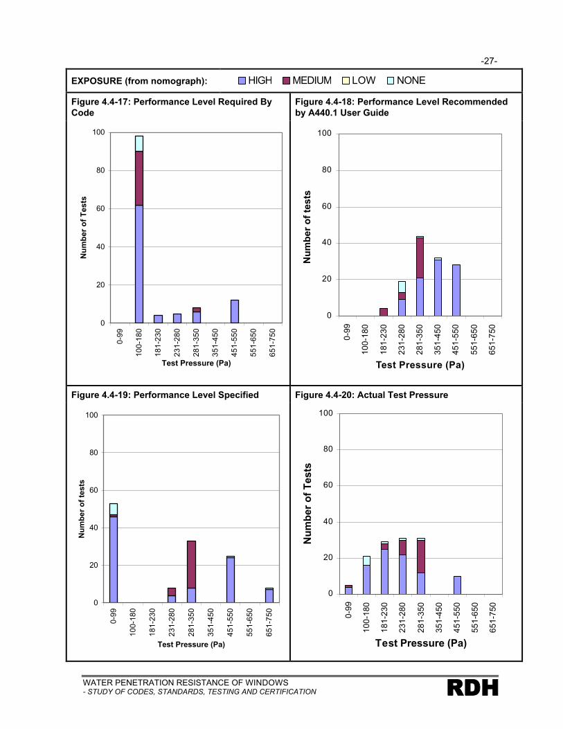
-27-
WATER PENETRATION RESISTANCE OF WINDOWS- STUDY OF CODES, STANDARDS, TESTING AND CERTIFICATION RDH
EXPOSURE (from nomograph):
Figure 4.4-17: Performance Level Required By Code
Figure 4.4-18: Performance Level Recommended by A440.1 User Guide
0
20
40
60
80
100
0-9
9
10
0-1
80
18
1-2
30
23
1-2
80
28
1-3
50
35
1-4
50
45
1-5
50
55
1-6
50
65
1-7
50
Test Pressure (Pa)
Nu
mb
er o
f T
ests
0
20
40
60
80
100
0-9
9
10
0-1
80
18
1-2
30
23
1-2
80
28
1-3
50
35
1-4
50
45
1-5
50
55
1-6
50
65
1-7
50
Test Pressure (Pa)
Nu
mb
er o
f te
sts
Figure 4.4-19: Performance Level Specified Figure 4.4-20: Actual Test Pressure
0
20
40
60
80
100
0-9
9
10
0-1
80
18
1-2
30
23
1-2
80
28
1-3
50
35
1-4
50
45
1-5
50
55
1-6
50
65
1-7
50
Test Pressure (Pa)
Nu
mb
er o
f te
sts
0
20
40
60
80
100
0-9
9
10
0-1
80
18
1-2
30
23
1-2
80
28
1-3
50
35
1-4
50
45
1-5
50
55
1-6
50
65
1-7
50
Test Pressure (Pa)
Nu
mb
er o
f T
ests
HIGH MEDIUM LOW NONE

-28-
WATER PENETRATION RESISTANCE OF WINDOWS- STUDY OF CODES, STANDARDS, TESTING AND CERTIFICATIONRDH
Failure Analysis by Leakage Path Category
The results of the window field testing are shown graphically in Figure 4.4-21 to 4.4-23 for the major
test categories.
Figure 4.4-21: Quality Assurance –Field Review During Construction
In Figure 4.4-21 it can be seen that the windows
tested for quality assurance reasons failed to meet
the expectations in 41% of the windows tested.
This is somewhat concerning since quality
assurance testing is generally performed on a
newly installed window that is not expected to have
problems. Failure in the quality assurance group
were predominately related to the window itself
failing and this is likely a result of improvements in
window to wall interface detailing in British
Columbia over the past few years. This result also
underscores the continuing need for better quality
control and improvements in the windows
themselves.
Figure 4.4-22: Investigation of Suspected Failure
Figure 4.4-22 shows the results of the testing
performed to investigate the cause of known
problems. In this category most of the tests failed
to meet expectations. This is not surprising since
water leakage was the likely reason they were
tested in the first place. Both perimeter interface
failures and window failures were significant
contributors to the problems in these tests.
8%
30%
3%
59%Pass
WindowFailure
Perimeter Failure
Perimeter and Window Failure
13%
61%
23%
3%Pass
WindowFailure
Perimeter Failure
Perimeter and Window Failure

-29-
WATER PENETRATION RESISTANCE OF WINDOWS- STUDY OF CODES, STANDARDS, TESTING AND CERTIFICATION RDH
Figure 4.4-23: Condition Assessment –Typical In-Service Performance
The result of the testing that was
performed as part of condition
assessment work to determine typical in-
service performance is shown in Figure
4.4-23. In this case windows that may or
may not be known to have problems are
tested to assess the typical performance
of the window and wall assemblies of the
building. In most cases these windows
have been installed for a number of
years prior to testing. The results of this
testing show significantly more failures
than the quality assurance testing as
would be expected since they have been
in-service for a longer period of time and
are generally installed into poorer
performing wall systems. Both window
and interface problems are significant
contributors to the leakage observed in
this testing.
Failure Analysis by Construction Type
Figures 4.4-24 to 29 present the failure rates for combustible and non-combustible construction.
Figures 4.4-24 & 25 indicate results for quality assurance tests; Figures 4.4-26 & 27 for condition
assessment tests and Figures 4.4-28 & 29 indicate the total failure rate for combustible and non-
combustible construction respectively.
For the quality assurance testing the higher failure rate in non-combustible construction probably
reflects the fact that much of the testing incorporated multiple (coupled) windows whereas the
combustible test were typically done on single windows. Since one failure in any test constitutes an
overall failure for the purposes of this study, the probability of failure in a multiple window sample
would be greater than in a single window test. What is alarming in an overall sense is the fact that a
significant number of failures occur during the quality assurance testing at the time of initial
construction. This underscores the need for continued improvement in both manufacturing and
installation practices.
10%
48%
32%
10%Pass PerimeterFailure
WindowFailure
Perimeter and Window Failure

-30-
WATER PENETRATION RESISTANCE OF WINDOWS- STUDY OF CODES, STANDARDS, TESTING AND CERTIFICATIONRDH
The very high rate of failure for the condition assessment testing in both types of construction reflect a
number of factors including:
• Windows have been in-service and therefore components and materials have aged leading to higher failure rates
• Testing during condition assessment work is often initiated because the windows are suspected to not be performing adequately
• Windows and installation practices are representative of standards in place at some point in the past, possibly prior to the general acceptance and use of the newer A440.1
8 and A440.4
9
standards, testing protocols and better installation practices in use today (in British Columbia)
When the two categories are added together to illustrate total failure rates the differing trends for
quality assurance test results and condition assessment test results somewhat offset each other
giving rise to more similar overall total failure rates.

-31-
WATER PENETRATION RESISTANCE OF WINDOWS- STUDY OF CODES, STANDARDS, TESTING AND CERTIFICATION RDH
COMBUSTIBLE CONSTRUCTION NON-COMBUSTIBLE CONSTRUCTION
Figure 4.4-24: Failure Rate - QA/QC Tests Figure 4.4-25: Failure Rate - QA/QC Tests
Figure 4.4-26: Failure Rate -Condition Assessment Tests
Figure 4.4-27: Failure Rate -Condition Assessment Tests
Figure 4.4-28: Total Failure Rate Figure 4.4-29: Total Failure Rate

-32-
WATER PENETRATION RESISTANCE OF WINDOWS- STUDY OF CODES, STANDARDS, TESTING AND CERTIFICATIONRDH
5. REVIEW OF CODES, STANDARDS AND CERTIFICATION PROCESSES
Mandated performance requirements for windows are provided through building codes and standards
documents as well as through non mandatory guides and certification programs. An overview of the
codes, standards and certification processes reviewed in this study is presented in Table 5.1.
Table 5.1: Overview of Codes, Standards and Certification Processes Reviewed
Building Codes Standards Certification
Canadian Standards Association (CSA) A440
7– sets out
classification levels and test requirements for windows, with authority having jurisdiction assigning minimum levels to be met. Refers to ASTM testing standards.
? ?
Canadian building codes(adopted at provincial or local levels) – sets out minimum provisions and requirements for windows in buildings. Makes reference to requirements set out in CSA A440
7.
A440.18 User
Selection Guide– how to select correctminimum levels and optionalrequirements.
A440.4–989
InstallationGuide – sets out methods and minimum requirementsfor both new installation and replacementinstallation of factory-assembledwindows.
CSA Windows & Doors Certification Program -(voluntary) certificationgranted on basis of meeting CSA A440 standards.Manufacturers obtain third-party assessment of their products to obtain this certification.
Canadian Construction Materials Centre (CCMC) Doors and WindowsEvaluation Program –voluntary performance-basedprogram to establish conformance to applicable codes and standards, including Canadian building code and CSA A440
7.
Testing performed by laboratories recognized by CCMC. Evaluation product listing provided to the public.
Proposed North American Fenestration Standard
14– would
combine/replace U.S. standards and CSA A440
7 Windows. Sets
out window classes and types, performance requirements and product designations.
Window-Wise Certification Program - managed by the Siding and Windows DealersAssociation of Canada to certify window installers in the replacement of window field (not applicable to new construction). Windows must be to CSA A440
7 standard,
and mandatory installation program based on A440.4
9
standard.
The building code requirements, standards documents, and certification programs have been
reviewed and specific “strengths” and “limitations” have been identified. “Strengths” should be

-33-
WATER PENETRATION RESISTANCE OF WINDOWS- STUDY OF CODES, STANDARDS, TESTING AND CERTIFICATION RDH
interpreted to mean areas where water penetration control issues are appropriately dealt with. It may
well be however, that the requirements could be enhanced to provide better guidance and direction
with respect to water penetration control. These opportunities are identified in the final chapter of this
report. More importantly, “limitations” should be interpreted to mean an area where either the
treatment of a water penetration control issue is not appropriate or where there is a need for
expanded scope or greater guidance on a particular issue. This does not necessarily mean that the
particular document or program being reviewed needs to be changed. It simply identifies an area
where more or better guidance is required. A discussion of the nature of the changes required and
how they might be incorporated into the overall code, standards, and certification framework is
contained in the final chapter of this report.
It is important to note that the design of buildings and the associated walls and windows must reflect a
multitude of requirements other than water penetration control including the type of occupancy,
building form, aesthetics, materials, interior and exterior environments with respect to other moisture
control functions, as well as initial and future costs. The documents and programs reviewed as part of
this study generally do not represent a manual on window and window to wall interface design for all of
these elements of performance and functions. The designer must consider the many performance
requirements and functions as well as guidance provided from other sources in order to fully develop
a design.
5.1 Review of Building Codes
The National Building Code of Canada has historically been a consensus based document with
decisions related to its content, and changes to its content, decided upon by committees
representative of the construction industry. Building codes can be prescriptive with respect to some
issues, while for other issues performance requirements are stated and there is a reliance on other
guidance documents or standards to address how to achieve the requirements. The extent to which
issues are addressed by the code is determined in response to input from industry. Our comments
with respect to the building code are therefore made in the context of it being an evolving document
that reacts to the needs of industry, some of which may be articulated through this report and study.
The review of relevant Canadian code documents has been undertaken based on the 1995 National
Building Code11
(NBC-95). This document is the model code upon which all of the currently legislated
provincial codes are based. The review has also been undertaken in the context of multi-unit
residential buildings which can generally be considered larger buildings in compliance with Section 2.1
of NBC-9511
. Therefore Parts 3, 4, 5 and 6 of NBC-9511
and similar sections of the applicable
provincial codes apply. With the exception of Article 2.4.2.2. (1) only Part 5 of NBC-9511
contains
requirements relevant to the water penetration resistance of windows. Several sections within Part 9

-34-
WATER PENETRATION RESISTANCE OF WINDOWS- STUDY OF CODES, STANDARDS, TESTING AND CERTIFICATIONRDH
(for smaller buildings) of NBC-9511
contain requirements for windows and it is also reviewed for
comparison purposes.
5.1.1 Requirements
The relevant requirements of NBC-9511
are presented in this section. Comments are provided in
section 5.1.2 of the report.
Part 2
Article 2.4.1.1. (1) is a general performance oriented requirement that applies to windows. Article
2.4.1.1. (1) is as follows:
2.4.1.1. Characteristics of Materials, Appliances, Systems and Equipment
1) All materials, appliances, systems and equipment installed to meet the requirements of this Code shall possess the necessary characteristics to perform their intended functions when installed in a building.
Part 5
Subsection 5.1.2. deals with the application of Part 5. Article 5.1.2.1. is as follows:
5.1.2.1. Separation of Environments
1) This Part applies to
a) the control of condensation in and on, and the transfer of heat, air and moisture through building elements and interfaces between building elements that separate
i) interior space from exterior space
ii) interior space from the ground, and
iii) environmentally dissimilar interior spaces, and
b) site conditions that may affect moisture loading on building elements that separate interior space from exterior space, and interior space from the ground
Article 5.1.4.1. addresses resistance to environmental loads as follows:
5.1.4.1. Resistance to Environmental Loads
1) Building components and assemblies that separate dissimilar environments shall
a) be designed to have sufficient capacity and integrity to resist or accommodate all environmental loads and effects of loads that may be reasonably expected, having regard to
i) the intended use of the building, and
ii) the environment to which the components and assemblies are subject, and
b) satisfy the requirements of this Part.

-35-
WATER PENETRATION RESISTANCE OF WINDOWS- STUDY OF CODES, STANDARDS, TESTING AND CERTIFICATION RDH
Article 5.1.4.2. Resistance to Deterioration is as follows and also references Appendix A of NBC-9511
:
5.1.4.2. Resistance to Deterioration
1) Except as provided in Sentence (2), materials that comprise building components and assemblies that separate dissimilar environments shall be:
a) compatible with adjoining materials, and resistant to any mechanisms of deterioration which would be reasonably expected, given the nature, function and exposure of the materials.
Appendix A contains the following relevant paragraph:
Building components must be designed with some understanding of the length of time over which they will effectively perform their intended function. Actual service life will depend on the materials used and the environment to which they are exposed. The design should take into consideration these factors, the particular function of the component and the implications of premature failure, the ease of access for maintenance, repair or replacement, and the cost of repair or replacement.
Article 5.2.1.1. and 5.2.1.2. address environmental loads as follows:
5.2.1.1. Exterior Environmental Loads
1) Except as provided in Sentences (2) and (3), climatic loads shall be determined according to Section 2.2.
Sentences (2) and (3) are not relevant to water penetration resistance of windows.
5.2.1.2. Interior Environmental Loads
1) Interior environmental loads shall be derived from the intended use and occupancy of the space.
Section 5.6. deals with Precipitation and is clearly the section that deals most directly with water
penetration issues and windows most directly. Article 5.6.1.1. is as follows:
5.6.1.1. Required Protection from Precipitation
1) Except as provided in Sentence (2), where a building component or assembly is exposed to precipitation, the component or assembly shall
a) minimize ingress of precipitation into the component or assembly, and
b) prevent ingress of precipitation into interior space
Sentence (2) is not relevant to water penetration resistance of windows.
Article 5.6.1.2. addresses specific materials and how they are used. Of particular interest is Sentence
(3) which is as follows:
3) Except as provided in Sentence (5), where materials or components applied to vertical assemblies are installed to provide required protection from precipitation and are covered in the scope of the standards listed below, the materials or components shall conform to the requirements of the respective standards:
….s)CAN/CSA-A440-M, “Windows”
Sentence (4) elaborates on the use of the CAN/CSA-A440-M standard as follows:

-36-
WATER PENETRATION RESISTANCE OF WINDOWS- STUDY OF CODES, STANDARDS, TESTING AND CERTIFICATIONRDH
4) Except as provided in Sentence 5), windows and sliding doors exposed to the exterior and covered in the scope of CAN/CSA-A440-M, “Windows”, or CAN/CGSB-82.1-M, “Sliding Doors”, shall conform at least to the water tightness requirements in CSA A440.1-M, “User Selection Guide to CAN/CSA-A440-M90 Windows”.
Sentence (5) is not generally relevant to water penetration resistance of windows.
Subsection 5.6.2. presents requirements for Sealing, Drainage, Accumulation and Disposal. Of
particular relevance to water penetration resistance of windows is Sentence 5.6.2.1-1) and 5.6.2.2-4)
which are as follows:
5.6.2.1. Sealing and Drainage
1) Except as provided in Sentence (2), materials, components, assemblies, joints in materials, junctions between components and junctions between assemblies exposed to precipitation shall be
a) sealed to prevent ingress of precipitation, or
b) drained to direct precipitation to the exterior
5.6.2.2. Accumulation and Disposal
4) Junctions between vertical assemblies, and sloped or horizontal assemblies, shall be designed and constructed to minimize the flow of water from the sloped or horizontal assembly onto the vertical assembly.
Article 5.6.2.1. also refers to Appendix A which contains the following relevant paragraph:
Providing a surface-sealed, durable, watertight cover on the outside of a building is difficult.Where there is a likelihood of some precipitation into a component or assembly, drainage is generally required to direct moisture to the exterior.
Part 9
Section 9.7. Windows and Skylights addresses requirements for windows in smaller buildings. With
respect to water penetration resistance the following clauses are of interest.
Sentence (1) of Clause 9.7.2.1. is as follows:
9.7.2.1. Window Standard
1) Windows shall conform to CAN/CSA-A440-M, “Windows” but need not meet air-tightness, watertightness and wind load resistance requirements more stringent than those for classifications A1, B1 and C1 in CAN/CSA-A440-M, “Windows”.
This sentence also refers to Appendix A which contains the following relevant paragraph:
CSA Standard CAN/CSA-A440-M, “Windows”, includes a window classification system that rates the assembly according to airtightness, watertightness and wind load resistance. The ratings achieved by each window are marked on the window and indicate the level of performance that can be expected. Article 9.7.2.1. has specified the lowest classifications (A1, B1, C1) since the NBC is a collection of minimum requirements only. However, designers or builders should consider windows with higher ratings, based on the height of the window above grade, climatic conditions, and the occupancy classification. CSA publishes a companion document to CAN/CSA-A440-M entitled CSA A440.1, “User Selection Guide to CSA Standard CAN/CSA-

-37-
WATER PENETRATION RESISTANCE OF WINDOWS- STUDY OF CODES, STANDARDS, TESTING AND CERTIFICATION RDH
A440-M, Windows”. This guide is intended to assist specifiers, manufacturers, and general users in selecting the window ratings appropriate for a particular building, based on its geographiclocation and height.
Article 9.7.4.2. is as follows:
9.7.4.2. Caulking Compound
1) Caulking shall be provided between window frames or trim and the exterior siding or masonry in conformance with Subsection 9.27.4.
Clause 9.20.13.3. (1)(e) addresses the location of flashing at windows:
9.20.13.3. Location of Flashing
1) Flashing shall be installed in masonry and masonry veneer walls
e) over the heads of window or door openings in exterior walls when the vertical distance between the top of a window or door frame and the bottom edge of the eave exceeds ¼ of the horizontal eave overhang
Clause 9.27.3.2. (2) & (4) discusses the installation of windows without a head flashing:
9.27.3.2. Installation
2) Except as provided in Sentence (4), flashing shall be applied over exterior wall openings where the vertical distance from the bottom of the eave to the top of the trim is more than one-quarter of the horizontal overhang of the eave.
4) Where a window or exterior door is designed to be installed without head flashing, the exterior flange of the window or door frame shall be bedded into a non hardening caulking material and the exterior flange screwed down over the caulking material to the wall framing to form a waterproof joint.
5.1.2 Discussion of Requirements
Part 5
Strengths
We have identified the following strengths within Part 5 of NBC-9511
with respect to water
penetration control in window assemblies and the window to wall interface:
• Article 5.1.4.2 requires that materials within assemblies are resistant to deterioration by mechanisms that would reasonably be expected. Window leakage activity and resulting moisture accumulation within walls leading to deterioration is clearly not an expected exposure condition for the materials within the wall assembly.
• Appendix A notes regarding the above Article provide guidance with respect to service life considerations in the design and selection of wall and window assemblies.
• The performance based requirements of Article 5.6.1.1 clearly require that water penetration not occur to the point where it is likely to cause damage.
• Article 5.6.1.2 requires compliance to the appropriate window standards, CSA A4407 and
CSA A440.18

-38-
WATER PENETRATION RESISTANCE OF WINDOWS- STUDY OF CODES, STANDARDS, TESTING AND CERTIFICATIONRDH
• Articles 5.6.2.1 and 5.6.2.2 draw attention to the fact that junctions between assemblies (the window to wall interface) need to be appropriately designed and detailed to prevent water penetration.
• Appendix A notes regarding the above Article warns about the difficulty in achieving a perfect surface-sealed barrier (face seal) on a building.
• In general Part 5 recognizes the need for flexibility in design by allowing the designer to consider the full range of variables in achieving a balanced design.
Limitations
We have identified the following limitations in the effectiveness of Part 5 with respect to water
penetration control in window assemblies and the window to wall interface:
• Although Article 5.2.1.1 identifies the needs to consider the exterior environmental loads and references climatic data for different locations, it does not explicitly acknowledge the micro climate effects of building form, and local topography which impact on the frequency and time of wetness due to rain.
• Although Article 5.6.1.1 addresses water penetration, it does not provide (nor do the Appendix notes) any guidance on design and selection of appropriate water penetration control strategies for various exposure conditions.
• Although Articles 5.6.2.1, 5.6.2.2 and associated Appendix notes address building interfaces, they do not provide any guidance on design and selection of appropriate water penetration control strategies for various exposure conditions.
Part 9
Strengths
We have identified the following strengths within Part 9 of NBC-9511
with respect to water
penetration control in window assemblies and the window to wall interface:
• Sentence 1) of Article 9.7.2.1 requires compliance to the minimum requirements of the appropriate window standards, CSA A440
7 and CSA A440.1
8.
• Appendix A notes regarding the above Sentence identifies the need to consider the A440.1
8 User Selection Guide to select windows for a particular site.
• Sentence 1) of Article 9.20.13.3 and Article 9.27.3.2.(2) indicate an understanding and explicit recognition that overhangs can have an impact on building exposure conditions
Limitations
We have identified the following limitations in the effectiveness of Part 9 with respect to water
penetration control in window assemblies and the window to wall interface:
• Part 9 does not acknowledge the fact that the rain exposure conditions for smaller Part 9 buildings can be as significant as for many larger Part 5 buildings. This arises because it is possible to have a building classified as a Part 9 building through the use of small building floor areas separated by fire walls. Unfortunately this method of determiningapplicability of Part 9 does not reflect the fact that the walls and windows of Part 5 and Part 9 buildings can have identical, and sometimes high, exposure conditions and should be designed accordingly.
-39-
WATER PENETRATION RESISTANCE OF WINDOWS- STUDY OF CODES, STANDARDS, TESTING AND CERTIFICATION RDH
• Part 9 does not acknowledge the micro climate effects of building form, and local topography which impact on the frequency and time of wetness due to rain.
• Part 9 provides no guidance on design and selection of appropriate water penetration control strategy.
• Sentence 1) of Article 9.7.4.2 deals with junctions between windows and adjacent wall assemblies in a very simplistic manner and does not adequately address all of the different types of wall assemblies, situations and exposure conditions.
• Part 9 is more restrictive with respect to design flexibility, although this flexibility can generally be provided for smaller buildings through the involvement of design professionals.
5.2 Review of Canadian A440 Window Standards
5.2.1 Introduction
The A440 series of window standards and special publications provides a set of performance oriented
and prescriptive requirements for all factory built windows. Of particular relevance to water
penetration control are standard CSA A440-007 Windows, special publication A440.1-00
8 User
Selection Guide to CSA Standard A440-00, Windows and standard A440.4-989 Window and Door
Installation.
The following sections examine how these three standards address water penetration resistance
associated with windows.
5.2.2 Requirements
Standard A440-00, Windows
The A440.1 publication is referred to in the preface to the A440-00 standard as follows:
Classification levels and test requirements provided in this Standard allow a purchaser or specifier to select windows suitable to their specific climatic conditions, height of installation, type of building, etc. The authority having jurisdiction assigns the minimum levels to be met. All other classifications and test requirements exceeding those specified by the authority having jurisdiction are considered optional. CSA Special Publication A440.1 complements the A440 Standard. The Guide (reference is presumed to be to A440.1) gives a detailed explanation of how to select the correct minimum level appropriate to the installation.
Clause 1.3 states:
This standard applies to combination and composite windows as limited by Clause 10.1.4.Mullions are tested for structural adequacy, and unless a combination or composite window has been tested as an assembly, air and water tightness at the component interface are not evaluated.
Clause 10.1.4 refers to more specific requirements for strength and stiffness of combination or
composite windows.

-40-
WATER PENETRATION RESISTANCE OF WINDOWS- STUDY OF CODES, STANDARDS, TESTING AND CERTIFICATIONRDH
Section 10 outlines test requirements for windows. Clause 10.3 addresses water penetration as
follows:
10.3 Water Tightness – All WindowsWhen tested in accordance with Clause 11.3
(a) no water shall penetrate the window assembly and cause wetting of the interior room surfaces;(b) no water shall pass through the window into the wall below the sill; and (c) no water shall remain trapped in the window assembly after the test pressure has been released. This shall be confirmed by observing the receding water level in the window assembly after the pressure has been released. Water retained as droplets or surface film due to surface tension within drained cavities shall not be considered evidence of failure of the test.
Section 11 of the standard describes test methods. Clause 11.1.3 refers to the test specimen size as
follows:
11.1.3Specimen size shall be in accordance with Table 10, except where the manufacturer wishes to demonstrate compliance of a smaller or larger model size ranges. Except as noted in Clause 4.2, compliance with this Standard shall be deemed to occur only up to the largest size tested.
Clause 4.2 discusses application or ratings relative to window size and is not directly related to water
penetration resistance issues. Table 10 is as follows:
Table 10Specimen Sizes for Performance Tests
Outside Dimension of main frame ± 100mm
Window Type Width, mm Height, mm
Vertically sliding 1000 1600
Horizontally sliding 1600 1000
Casement 700 1600
Projecting 1000 1000
Fixed 2000 2000
Tilt-and-Turn 1000 1600
Clause 11.1.4 refers to the sample provided by the manufacturer as follows:
11.1.4Each test specimen shall be provided by the manufacturer installed in accordance with CSA Standard A440.4 within a sealed buck to facilitate mounting in the test apparatus.
Clause 11.3 discusses the test procedure as follows:
11.3 Water Tightness11.3.1The window shall be installed in the test chamber in accordance with the manufacturer’s instructions for field installation, with all operable lites in the closed and latched position and exterior insect screens in place.

-41-
WATER PENETRATION RESISTANCE OF WINDOWS- STUDY OF CODES, STANDARDS, TESTING AND CERTIFICATION RDH
11.3.2The test shall be conducted in accordance with ASTM Standard E547 at the pressure differential selected from Table 2. The test period shall consist of four cycles, each cycle consisting of 5 min with pressure applied and 1 min with pressure released, during which the water spray shall be continuously applied.
Table 2 is as follows:
Table 2: Water Tightness
Window rating
For use in small buildings
For use in other buildings Pressure differential, Pa
Storm - 0
B1 B1 150
B2 B2 200
B3 B3 300
- B4 400
- B5 500
- B6 600
- B7 700
Special Publication A440.1, User Selection Guide to CSA A440-00, Windows
The preface to the User’s Guide states the purpose of the guide to be as follows:
(a) direct users to those areas in which a selection must be made from among optional requirements of the Standard; (referring to A440-00)(b) provide users with the information required to select products suitable for a specific application and geographic location within Canada; and(c) provide users with the background and intent of the tests and requirements outlined in the Standard.
The preface goes on to provide the following cautionary remarks:
As the National Building Code typically specifies only minimum performance requirements, it is strongly recommended that appropriate performance ratings are specifically selected to meet climatic conditions and occupancy classifications.
The guide explains the basis for selecting a water tightness B rating as being related to the Driving
Rain Wind Pressure (DRWP). DRWP is based on Environment Canada data for wind pressure
coincident with the presence of rain for a given location at a specified height of 10m above ground
level. For small buildings the reference DRWP is based on one chance in five of being exceeded in
any one year, or a 20% probability that water leakage may occur over a period of one year. For other
buildings the reference DRWP is based on one chance in 10 of being exceeded in any one year, or a
10% probability that water leakage may occur over a period of one year.

-42-
WATER PENETRATION RESISTANCE OF WINDOWS- STUDY OF CODES, STANDARDS, TESTING AND CERTIFICATIONRDH
As an example, consider a 25m high residential building in Vancouver, BC. From Table UG-1 in the
Guide the reference DRWP is given as 220 Pa at 10m above grade. From Table UG-2 in the Guide,
for a reference pressure of 220 Pa and a building height of 25m, the DRWP is given as 286 Pa which
corresponds to a B3 water tightness rating requirement.
Standard A440.4-98, Window and Door Installation
The version of the A440.4 standard reviewed for this study is the first edition of the standard. The fact
that some of the comments may be more critical, and recommendations for additions and change
more profound should be considered in the context of a standard that is in a relatively early stage of
refinement.
Section 1 of the standard outlines the scope and limitations of the standard. Clauses 1.1 to 1.3 are as
follows:
1.1
This Standard sets forth methods for both new installation and replacement installation of factory-assembled windows and exterior doors that are intended for vertical installation in small buildings primarily used for residential occupancy. (The definition of small building provided in the standard is structures limited to 3 storeys with no limit to the floor area).
1.2
This Standard provides minimum requirements that will help to ensure the installation of windows in an effective manner, such that the performance of the window, as established by testing to the requirements of CSA Standards A440 and A440.2, is not compromised.
1.3
This Standard applies to the installation process from pre-installation procedures to post-installation procedures. It does not apply to the fabrication or assembly of units, whether such fabrication takes place in a factory or at the installation site.
Clause 1.5 states the following:
1.5
This standard does not apply to the
a) selection of windows or doors for a given applicationb) selection of other products for use in the installationc) installation of windows or doors in seasonal dwellingsd) installation of storm windows or storm doorse) maintenance of installed windows or doors; orf) rebuilding of windows or doors.
Finally there is one sentence in Clause 1.6 that states This Standard does not address the
qualifications and skills that a window installer should possess.
Section 5 of the Standard is titled General Principles. Two clauses (5.1.1 and 5.3) are particularly of
interest in the context of the current study:

-43-
WATER PENETRATION RESISTANCE OF WINDOWS- STUDY OF CODES, STANDARDS, TESTING AND CERTIFICATION RDH
5.1.1
This standard recognizes that the integration of the window or door into the wall must be done in a manner that
a) ensures a structural tie that will reduce or eliminate downward load transfer, permit differential movement of the window and the wall in the same plane as the window, and maintain forced entry resistance;b) ensures continuity of the air barrierc) restricts vapour flow;d) shelters the unit from the weather;e) reduces the risk of condensation and thermal heat loss;f) maintains ease of operation;g) prevents insect entry;h) maintains satisfactory performance throughout its service life;I) limits sound transmission;j) is aesthetically acceptable; andk) prevents the entry of water into the wall assembly.
5.3 Continuity with the Wall Systems
Continuity shall be maintained between elements in the window or door and the wall to provide weather protection, airtightness, and resistance to heat flow and vapour diffusion.
Clause 6.6.11 RainScreen Method is found within section 6.6 which deals with air leakage control
around the window. This section and the one that follows - 6.7 Weathertightness are the key aspects
of the Standard with respect to rain penetration control. They are reproduced here in their entirety:
6.6.11 Rain Screen Method
6.6.11.1
The primary intent of this installation method is to provide improved water penetration resistance by incorporating a second layer of resistance against water penetration, which is drained to the exterior.
6.6.11.2
The following opening preparation method provides an increased level of water penetration resistance for the window installation and the interface with the adjacent wall system. This method is recommended in areas of high and prolonged exposure to wind-driven rain on new construction, and on complete tearout replacements in the following circumstances:
(a) on buildings greater than 4 m (13 ft) in height without adequate overhang protection at the top of the wall; or
(b) if the durability of the internal frame-to-frame sealants in the window is less than the wall cladding, and the failure of the internal sealants could allow water penetration sufficient to cause damage to the wall system.
Note: Many window systems have drained internal cavities or gutters that accommodate water penetration. This water is drained back to the exterior through drain holes in the framing system that are left permanently open. This type of system is an example of a window that may rely on sealants to maintain watertight frame joints for water management.
6.6.11.3
The opening in the wall system and the connection to the window frame shall be designed to manage any incidental water leakage through the window assembly, or through the interface withthe adjacent cladding system, by preventing penetration past the interior plane of water resistance in the wall system.

-44-
WATER PENETRATION RESISTANCE OF WINDOWS- STUDY OF CODES, STANDARDS, TESTING AND CERTIFICATIONRDH
6.6.11.4
The windows shall be installed with a watertight seal around the interior perimeter of the window frame to a water-impermeable membrane or flashing applied continuously to the rough opening and adequately lapped, sloped, and sealed so that incidental water penetration is drained to the exterior of the interior plane of water resistance in the adjacent wall system (see Figure 24).
6.6.11.5
The sill of the rough opening shall be sloped toward the exterior.
6.6.11.6
Window fasteners at the sill of the rough opening shall not penetrate the horizontal surface of the waterproof membrane or flashing layer so as to avoid penetrations in the interior plane of water resistance.
6.6.11.7
The exterior perimeter of the window frame shall be sealed to the exterior cladding, and a minimum 6% sloped head and sill flashings shall be provided where required in accordance with Clause 6.7.
Note: Some wall systems may require a metal sill flashing to seal the exterior perimeter of the window while still allowing drainage from the area between the window frame and rough opening.
6.6.11.8
Insulation shall be provided between the frame and the rough opening in accordance with Clause 6.5, without impeding drainage between window sill and rough opening.
6.6.11.9
The air barrier in the adjacent wall shall be sealed to the window frame in accordance with the applicable method in Clauses 6.6.1 to 6.6.10.
6.7 Weathertightness
6.7.1 General
6.7.1.1
The window shall be sealed to the adjacent wall so that the underlying water management principles of the wall system are carried through the intersection to the appropriate components in the window assembly.
Note: All wall cladding systems are designed to manage the penetration of water. Many cladding systems accept that some water will penetrate past the exterior cladding, but manage water penetration by draining this water and diverting it back to the exterior. This drainage water is generally prevented from entering the moisture-sensitive areas of the wall assembly and the building by sheathing papers and membranes installed within the assembly. It is important that the water management strategy employed by the adjacentwall system be understood and carried through the interface with the window system. This will ensure that the window installation is capable of preventing penetration past the intended plane of water resistance in the wall to regions which may be sensitive to repeated wetting.

-45-
WATER PENETRATION RESISTANCE OF WINDOWS- STUDY OF CODES, STANDARDS, TESTING AND CERTIFICATION RDH
6.7.1.2
A weather barrier consisting of flashings and seals shall be created to preclude the entry of water into the wall cavity and/or the rough opening gap. Flashings shall be installed to drain water away from the window or door to the exterior, while the seals shall be installed to prevent the entry of water, snow, dust, and insects into the rough opening gap.
6.7.1.3
Wherever possible, the cavity created between the newly installed window or door and the building veneer shall be covered and sealed with properly installed capping materials. Capped installations shall have the capping materials integrate with or seal to the perimeter of the newly installed window or door in a watertight manner. Capping shall be installed in such a manner as to allow ventilation and moisture to escape from under the capping. Non-capped installations shall use suitable sealing materials and procedures to create a weathertight seal between the newly installed window or door frame and the opening into which it is installed.
The sequence of construction shall allow for installation of the flashing at the proper time. Felts or other building paper materials shall be lapped over the head flashing or nailing flange to shed water to the exterior. The installed weatherseal shall not interfere with drainage holes in the window.
Note: The flashing configuration will depend on the surrounding construction. Where required, the flashing detail will be dealt with either before or after the window is placed into the rough opening. In some cases, the window or door manufacturer may supply special moulding or flashing for the window or door. In other cases, flashing materials will be used in conjunction with the application of the finish siding.
6.7.1.4
Window systems utilizing internal drainage paths to drain internal cavities within the window system shall be installed in the opening in such a way as to drain intentional drainage paths to the exterior of the adjacent wall system, unless the wall system has been specifically designed to accommodate the expected volume of water.
Note: The sensitivity of wall assembly components to moisture penetration behind the exterior cladding varies with each assembly. Cladding systems that attempt to prevent water penetration past the exterior cladding can be extremely sensitive to moisture penetration past the exterior cladding. Cladding systems that incorporate vapour permeable sheathing membranes, such as building papers and housewraps, allow small levels of water penetration to drain behind the exterior cladding. In these systems, the amount of water that can be managed by the wall system is a function of the sheathing membrane’s resistance to water and the ability for the cavity behind the cladding to drain and ventilate. In the above systems, it is generally better to drain intentional drainage paths in the window assembly to the exterior of the cladding, unless the expected frequency of wetting and volume of water is very low.
Cladding systems that incorporate a waterproof membrane, such as self-adhesive modified bitumen, on the interior of the drainage cavity are less sensitive to water and can accommodate more frequent wetting. Such wall systems can usually be designed to accept water from the intentional drainage of glazing cavities and window frames.
6.7.2 Exterior Sill Flashing
6.7.2.1
There shall be a minimum 6% slope on sills to the exterior.
6.7.2.2
The sill ends shall prevent water from entering the walls at the lower corners of windows.Note: Upstands could be used to prevent water from entering the walls at the ends of the sill.
6.7.2.3
All sills shall have a drip edge to prevent the backflow of runoff water.

-46-
WATER PENETRATION RESISTANCE OF WINDOWS- STUDY OF CODES, STANDARDS, TESTING AND CERTIFICATIONRDH
6.7.2.4
Two parallel beads of sealant shall be applied below door thresholds. This is critical to ensure weathertightness of the door.
6.7.3 Head Flashing
6.7.3.1
If the distance between the top of the window or door trim and the underside of the soffit exceeds one quarter of the soffit overhang, head flashing or a drip cap shall be installed.
Note: A flashing is needed even in a face-sealed wall system (ie, in a wall system in which the exterior finish is a component of the air barrier system and fully sealed) to act as a drip to deflect water away from the surface of the window. In a face-sealed wall system, however, the flashing must be sealed to the exterior finish.
6.7.3.2
The head flashing shall
(a) be a continuous piece long enough to cover the entire window or door head;(b) extend upward behind the wall sheathing paper at least 50 mm (2 in);(c) extend the leading edge over the window rim to form a drip over the brick mould; and(d) extend horizontally 6–12 mm (1/4–1/2 in) past the trim at the top corner of the window or door.
To finish, the siding veneer shall counterflash the header flashing.
6.7.3.3
As an alternative to flashing, when the building is finished with siding, a flange for the purpose of shedding water may be provided as an integral part of the frame. Such a flange shall be bedded into non-hardening sealant and fastened with screws to form a watertight joint with the wall sheathing.
6.7.3.4
Flashings shall be sloped to prevent water from running across and entering the wall at upper corners of windows.
6.7.3.5
Segmented flashings that are not constructed with welded or waterproof joints shall have a secondary waterproofing membrane installed under the flashing to prevent water penetration.
6.7.3.6
Siding shall be mounted 6 mm (1/4 in) above the flashing to avoid wicking action.
6.7.4 Exterior Perimeter Sealing
6.7.4.1
The exterior joints between window frames and adjacent cladding shall be carefully sealed to prevent the penetration of water.
6.7.4.2
Sealants recommended by the window manufacturer are preferred. Sealants shall be selected and applied in accordance with the sealant manufacturer’s instructions with respect to surface preparation and application procedures. Sealants work best in compression between two parallel surfaces, not at 90°.(see Figure 25).Note: Sealing to the sheathing below the siding serves to enhance the longevity of the sealant by reducing its exposure to the elements and to the thermal movement associated with most siding materials.

-47-
WATER PENETRATION RESISTANCE OF WINDOWS- STUDY OF CODES, STANDARDS, TESTING AND CERTIFICATION RDH
6.7.4.3
To limit vertical load transfer between the lintel and the frame head, the seal at the top of the window shall be designed to accommodate expected movements without undergoing permanent deformation or transferring loads to the frame or glazing, which could be detrimental to the window. An elastic seal with a low modulus of elasticity shall be used.
6.7.4.4
Backer rods shall be used when installing sealant such that the depth of the sealant is equal to half the width of the joint up to the sealant manufacturer’s recommended thickness (see Figure 26). Backer rods shall not be punctured during installation. Off-gassing of punctured backer rodscan cause sealant failure.
6.7.4.5
When a sill extension is required, the slope of the sill shall be continued, and at the junction point with the sill, the extension shall be sealed against water leakage.
6.7.4.6
Butt joints in sill flashings and expansion joint covers or corner plates shall be sealed to prevent water penetration.
Figures 14 to 24 are included in the standard to illustrate the air leakage control techniques discussed
in section 6.6 of the Standard.
Figure 5.2.2-1: Sample of figure from A440.49 standard that illustrates air tightness concepts but is fundamentally flawed from a water penetration control perspective for anything but very low exposure conditions.

-48-
WATER PENETRATION RESISTANCE OF WINDOWS- STUDY OF CODES, STANDARDS, TESTING AND CERTIFICATIONRDH
5.2.3 Discussion of Requirements
A440.0
Strengths
We have identified the following strengths within A4407 with respect to water penetration control
in window assemblies and the window to wall interface:
• It provides a consistent basis for the evaluation water penetration performance.
• It provides for different water penetration resistance levels.
• It references an established lab test protocol (ASTM E547) so that results of testing are comparable and repeatable.
Limitations
We have identified the following limitations in the effectiveness of A440 with respect to water
penetration control in window assemblies and the window to wall interface:
• The standard is fundamentally intended for evaluation of manufactured components and therefore does not consider water penetration resistance of installed window assemblies.It therefore does not require the evaluation of the performance of the interface between windows and adjacent wall assembly.
• A4407 does not consider the micro climate effects of building form, and local topography
which impact on the frequency and time of wetness due to rain.
• Although there are some prescriptive requirements that address durability of components or materials within a window assembly, A440
7 does not generally reflect any
consideration for the durability of the water penetration resistance for the window assembly.
• The evaluation procedure does not reflect the varying long term risk of water penetration associated with different water penetration control strategies (rainscreen vs. face seal).
• The requirements do not consider performance of combination windows such as strip windows (horizontally coupled) or window wall (vertically and horizontally coupled) with respect to water penetration control.
• The allowance for a window manufacturer to test samples of lesser or greater sizes than prescribed in Table 10 makes it difficult to directly compare performance between types of windows and manufacturers.
A440.1
Strengths
We have identified the following strengths within A440.18 with respect to water penetration
control in window assemblies and the window to wall interface:
• The guide provides a rational basis for selection of test pressure differential based on climatic data for specific geographic locations and building height.

-49-
WATER PENETRATION RESISTANCE OF WINDOWS- STUDY OF CODES, STANDARDS, TESTING AND CERTIFICATION RDH
Limitations
We have identified the following limitations in the effectiveness of A440.18 with respect to water
penetration control in window assemblies and the window to wall interface:
• It is not clear that there is any rational basis for the use of DRWP as the primary factor for establishing a rating system for effective water penetration control.
• The guide provides a basis for choosing B ratings that are significant in the context of relatively infrequent wind driven rain, whereas micro climate factors are not considered (except for height above ground), yet are significant in every rainfall event.
• The use of the 1 in 5 DRWP criteria for small buildings vs. 1 in 10 DRWP criteria for larger buildings does not reflect the reality of high exposure conditions that can occur with many buildings that are considered ‘small’ in NBC-95
11.
• The guide utilizes climate data for a particular elevation above the ground level. Whilethis may be appropriate for simple low rise structures set on simple sites, it is not appropriate for more complex potentially higher pressure regimes associated with high-rise buildings or with low-rise buildings situated on exposed sites.
A440.4
Strengths
We have identified the following strengths within A440.49 with respect to water penetration control in
window assemblies and the window to wall interface:
• It represents a first attempt at integrating and ensuring continuity of critical barriers, and installation requirements at the interface between the window and adjacent wall assemblies.
• The standard is intended to apply to the installation process from pre-installation stages to post-installation procedures.
• Clauses 6.6.11 and 6.7 provide some sound fundamental principles for water penetration control associated with the interface between the window and the wall.
• The ASTM E547 test protocol referenced by A440.07 has proven to be a useful evaluation tool
and we have no recommendations for changes in the requirements or application of the test protocols.
Limitations
We have identified the following limitations in the effectiveness of A440.49 with respect to water
penetration control in window assemblies and the window to wall interface:
• The standard currently provides a great deal of guidance and examples with respect to performance issues such as air tightness and support of glazing units and disproportionately few examples illustrating the principles of water penetration control.
• Clause 5.1.1 lists many of the functions that a window to wall interface must achieve. Waterpenetration control is inappropriately included as the last item on the list suggesting a lower priority for this function. It should be the first item in the list and be reworded to address water penetration directly to the interior as well as into the wall assembly.
• Clause 6.6.11 titled the Rain Screen Method is inappropriately included within the air leakage control portion of the guide.

-50-
WATER PENETRATION RESISTANCE OF WINDOWS- STUDY OF CODES, STANDARDS, TESTING AND CERTIFICATIONRDH
• Clause 6.7.4 suggests that sealant must be used and is fundamental to rain penetration control at the window perimeter. This is not the case for many applications.
• Many of the requirements for flashing are very prescriptive, limiting the ability to design other appropriate details.
• Clause 6.7.3.3 implies that the sheathing forms part of the exterior moisture barrier. This is not appropriate for most materials
• Reference and requirements for some specific materials are present in the standard, however the standard does not reference many materials that are in common use in construction (such as self adhesive membranes).
• Several of the figures illustrating air tightness concepts are inappropriate from a water penetration control perspective. An attempt should be made to illustrate details that will effectively perform all required functions along with the differences in installation technique that are required for different window and wall rain penetration and air leakage control strategies.
5.3 Review of Proposed North American Fenestration Standard
5.3.1 Introduction
At the time of the preparation of this report a North American standard for window performance was
being developed. It is titled North American Fenestration Standard – Voluntary Performance
Specification for Windows, Skylights, and Glass Doors14
(NAFS). This standard is intended to
promote consistency throughout North America by presenting a unified approach for the various
aspects of window performance. It combines AAMA/NWWDA 101/I.S. 2-97 Voluntary Specifications
fro Aluminum, Vinyl (PVC) and Wood Windows and Glass Doors, and AAMA/WDMA 1600/I.S. 7,
Voluntary Specification for Skylights and CSA A4407 Windows.
The following sections examine how the new standard proposes to address water penetration
resistance associated with windows.
5.3.2 Requirements
Window Classes and Types
The proposed standard provides for several levels of performance by establishing five classes of
windows. The classes are designated as residential (R), light commercial (LC), commercial (C),
heavy commercial (HC), and architectural (AW). It is intended that a window performance class is
selected or specified based on the assessment of factors such as climatic conditions, height of
installation, type of building, window size and desired durability. The following is provided in the draft
standard (part of clause 0.3.1) as a guide to determine which class of window is likely best suited for a
particular application:
(a) residential (R) - commonly used in one and two family dwellings. In Canada, “residential” is limited to a floor area of 600m² in buildings with no more than three floors;(b) light commercial (LC) – commonly used in low-rise multi family dwellings, low-rise

-51-
WATER PENETRATION RESISTANCE OF WINDOWS- STUDY OF CODES, STANDARDS, TESTING AND CERTIFICATION RDH
professional offices (doctor, dentist, lawyer), libraries, and low-rise motels;(c) commercial (C) – commonly used in lighter use industrial buildings and factories, hotels, and retail sales buildings;(d) heavy commercial (HC) – commonly used in hospitals, schools, institutions, dormitories, government or public buildings, and other buildings with increased loading requirements; and(e) architectural (AW) – commonly used in hospitals, schools, institutions, and public buildings, or in high-rise buildings to meet increased loading requirements. Also commonly used in buildings where possible misuse of the fenestration products is expected.
NAFS14
establishes a minimum set of performance criteria known as Gateway Requirements that
must be met in order for a product considered part of a particular window class (R, LC, C, HC, AW).
The primary requirements include size, air leakage resistance, water penetration resistance, uniform
load, and forced entry resistance.
NAFS14
also differentiates between products on the basis of operable unit type and refers to this as
product type.
Water Penetration Performance Requirements
The water penetration resistance performance of the different classes of windows is based on a
minimum design pressure. The designation for each window also incorporates a designation for
differing product types (primarily operable unit type) within each window performance class. Clause
0.3.3 describes this designation system and the minimum pressure categories as follows:
Performance is based on design pressure, which is designated by a number following the type and class designation. For example, a double-hung residential window is designated H-R15 or H-RM720. The number, in this case “15” or “720”, establishes the design pressure of 15 psf or 720 Pa. If the rating is desired in metric units, the design pressure in pascals shall be preceded by an “M”. The structural test pressure for all windows, skylights, and glass doors is 50% higher that the design pressure. The water resistance test pressure for all R, LC, C, and HC windows, skylights, and glass doors is a minimum of 15% of the design pressure. The water-resistancetest pressure for all AW windows, skylights, and glass doors is a minimum of 20% of the design pressure. The water-resistance test pressure should never be less than 140 Pa (2.86psf). Water test pressure should be capped at 720 Pa (15psf).
The minimum pressures are presented in Table 2 referenced by Clause 0.3.4 as follows:
Table 2Minimum Design Pressures, Structural Test Pressures, and Water Resistance Test Pressures
ProductPerformanceClass
Minimum Design Pressure, Pa(psf)
Minimum Structural Test Pressure, Pa(psf)
Minimum Water Resistance Test
Pressure, Pa(psf)
Residential 720 (15) 1080 (22.5) 140 (2.86)
Light Commercial 1200 (25) 1800 (37.5) 180 (3.75)
Commercial 1440 (30) 2160 (45.0) 220 (4.5)
Heavy Commercial 1920 (40) 2880 (60.0) 290 (6.00)
Architectural 1920 (40) 2880 (60.0) 390 (8.00)

-52-
WATER PENETRATION RESISTANCE OF WINDOWS- STUDY OF CODES, STANDARDS, TESTING AND CERTIFICATIONRDH
Optional higher pressures can be used for products and incorporated into the designation. The
design pressure and corresponding designation increases is multiple increments of 240 Pa (5 psf) to a
maximum of the gateway design pressure (see Table 2 above) plus 2880 Pa (60 psf) with the
exception of AW windows that have no maximum limit.
The test method specified is a four cycle water penetration resistance test in accordance with ASTM
Standard E547. There are no field testing requirements for the installed assembly nor is the interface
between the window and wall assembly considered part of the test.
Product Designations
Windows are designated with a four part code that includes product type, performance class,
performance grade (design pressure), and maximum size tested. The following is an example of this
designation:
Project Specific Requirements
Clause 0.3.2 presents a general requirement to consider selection of windows based on project
specific performance requirements as follows:
Product selection should always be based on the performance requirements of the particularproject and not solely on the general suggestions outlined above (reference is to article 0.3.1).For example, many residential buildings are built in locations subject to severe weather conditions that require higher performance fenestration products than those that meet only the residential requirements. On the other hand, many hospitals, schools, institutions, etc., successfully use products meeting residential, light commercial, or commercial requirements.
5.3.3 Discussion of Requirements
Strengths
We have identified the following strengths within NAFS14
with respect to water penetration control in
window assemblies and the window to wall interface:
• It provides a consistent basis for the evaluation of water penetration performance.
• It provides for different water penetration resistance levels.
Maximum Size Tested (Width in mm x Height in mm)
Performance Grade (Design Pressure)
Product Type (Horizontal Slider)
Performance Class (Light Commercial)
HS – LC 30 700x1000

-53-
WATER PENETRATION RESISTANCE OF WINDOWS- STUDY OF CODES, STANDARDS, TESTING AND CERTIFICATION RDH
• It references an established lab test protocol (ASTM E547) so that results of testing are comparable and repeatable. The ASTM E547 test protocol referenced by NAFS
14 has proven
to be a useful evaluation tool and we have no recommendations for changes in the requirements or application of the test protocols.
• The establishment of window classes incorporating multiple performance criteria provides a framework for potentially distinguishing between more and less durable water penetration performance.
• NAFS14
specifies water penetration test pressure differentials as a percentage of the design pressure used for structural calculations and testing. This method is simpler than the A440 method and depending on how the design pressures are determined could provide the ability to account for the higher peak pressures that may occur due to microclimate and building form effects.
• Clause 0.3.2 acknowledges the existence of project and site specific exposure conditions that may dictate product selection.
Limitations
We have identified the following limitations in the effectiveness of NAFS14
with respect to water
penetration control in window assemblies and the window to wall interface:
• Like A440, NAFS14
is fundamentally intended for evaluation of manufactured components and therefore does not consider water penetration resistance of installed window assemblies. It therefore does not require the evaluation of the performance of the interface between windows and adjacent wall assembly.
• NAFS14
does not provide guidance on the consideration of micro climate effects of building form, and local topography which impact on the frequency and time of wetness due to rain.
• The concept of window classes could be advantageous for mandating different levels of performance and durability. However, the current NAFS
14 classes do not relate to water
penetration performance, nor is it immediately evident what the water penetration resistance is from the designation.
• NAFS14
does not reflect any direct consideration for the durability of the performance achieved in standardized testing procedure.
• There are no prescriptive requirements in NAFS14
that address durability of components and materials.
• The evaluation procedure does not reflect the varying long term risk of water penetration associated with different water penetration control strategies (rainscreen vs. face seal).
• The requirements do not consider water penetration performance of combination windows.
• NAFS14
utilizes a different definition for its failure criteria in water penetration testing. This different criteria potentially leads to water being retained within the frame and negatively impacting the durability of frame sealants and insulating glass units.

-54-
WATER PENETRATION RESISTANCE OF WINDOWS- STUDY OF CODES, STANDARDS, TESTING AND CERTIFICATIONRDH
5.4 Review of Window Certification Processes
5.4.1 Introduction
In this chapter, a summary of the different Canadian window certification programs is presented. We
have also included, within the general concept of certification, the evaluation or listing programs.
In order to fully understand the current certification process, we provide this brief historical review of
the certification programs precursors. Prior to the existence of the Canadian Windows and Doors
Manufacturers Association (CWDMA) voluntary certification program for windows, patio-doors, door
lites and insulated residential entry systems in 1994, there were two product listing programs; the
Canada Mortgage and Housing Corporation (CMHC) listing and the Department of National
Defence (DND) listing. These two listing programs required that the window manufacturer submit a
window test report, from an independent laboratory, which confirmed window performance in
accordance with the applicable window standard. Those listings were valid for 5 and 2 years
(respectively) without much quality control verification or even product design change verification. The
programs were voluntary and it was the window manufacturers’ responsibility to inform the listing body
of any change or modification on his product during the validity period of the listing. Despite the
limitations of these programs, they were very popular within the window industry, partly due to the
relative low cost of the programs as well as the necessity to be listed in order to participate in some
projects such as CMHC financed projects and DND construction projects. Those programs were very
helpful in the development of the certification process, as they build-up industry and user awareness
on the benefit of evaluating window performances.
The two current remaining evaluation or certification programs are respectively the Canadian
Construction Material Centre (CCMC) program created in 1988 and the CSA International (CSA)
Windows and Doors Certification Program which replaced the CWDMA certification program on
January 1st 2000. The Department of National Defence listing, to our knowledge, no longer exists.
There is another certification program related to the window industry, the Siding And Window
Dealers Association of Canada (SAWDAC) ‘’Window Wise’’ program. This program is related
specifically to replacement windows.
5.4.2 CSA Windows and Doors Certification Program
Regulatory Organization
The CSA Windows and Doors Certification Program is managed by CSA International and endorsed
by the Canadian Windows and Doors Manufacturers Association (CWDMA).

-55-
WATER PENETRATION RESISTANCE OF WINDOWS- STUDY OF CODES, STANDARDS, TESTING AND CERTIFICATION RDH
Program Objective
The main objective of the certification program is to allow manufacturers to obtain a third-party
assessment of their products, in order to differentiate themselves in the market place. The
assessment includes several requirements to demonstrate that the tested product performance
relates to production line product performance. Certified products are labeled with the CSA Mark.
This voluntary performance-based program covers windows, sliding patio doors and insulated steel
doors for applicable properties such as:
• Air tightness;
• Water tightness;
• Wind load resistance;
• Forced entry resistance;
• Screen strength;
• Ease of operation;
• Sash strength and stiffness;
• Mandatory requirements;
• Energy performance (optional);
• Condensation resistance (optional).
This service from CSA International is available to Canadian manufacturers and other companies
selling products into Canada.
Applicable Standards
The certification is granted on the basis of the following Canadian Standards:
• CSA International’s CSA A4407 Window Standard;
• CSA International’s CSA A440.2 Window and Sliding Glass Door Energy Rating Standard;
• CSA International’s CSA A453 Hinged Door Energy Rating Standard;
• Canadian General Standards Board CGSB 82.1 Sliding Glass Door Standard;
• Canadian General Standards Board CGSB 82.5 Insulated Steel Door Standard.
Program Requirements and Certification Process
The CSA International Window and Door Certification Program requires the following from the
manufacturers:
• Fill out an application form for each product line and/or each manufacturing plant where certified products will be fabricated;
• Supply CSA with physical description of the product (e.i. publicity leaflet, data sheet, assembly and component drawings, photograph, etc.)
-56-
WATER PENETRATION RESISTANCE OF WINDOWS- STUDY OF CODES, STANDARDS, TESTING AND CERTIFICATIONRDH
• Supply CSA with a list of all components or materials used in the product, including the manufacturers’ names, model or catalogue designations;
• Describe any alternate materials or components that might be used in the manufacturing process;
• Supply the model or catalogue numbers to be covered by this certification, and the similarities between models that might be covered under the same product line;
• Demonstrate that a quality assurance system is in place at each manufacturing facilities andsupply CSA with copies of quality manuals and quality assurance procedures;
• Supply CSA with an administrative description of the company and pay accreditation fees to CSA;
• Set appointment with the CSA staff member assigned to your project in order for him or her to perform the first plant visit, which will include witnessing fabrication of the product to be tested for Standard compliance;
• Set appointment with a CSA accredited testing laboratory, inform them that you require tests for CSA certification purpose and ship to their facility the CSA identified test specimen;
• Upon testing completion the laboratory will supply CSA with a original copy of the test report, with a description of any modifications to the product;
• Answer to any findings from CSA that might require action on the manufacturer part;
• Once the product is ready for certification, a proposed Certification Record will be submitted by CSA and the manufacturer will be ask to confirm it as the published record of the product;
• If the product meets all the requirements, CSA International will issue a Certification Report and Certificate of Compliance. The manufacturer may then use the CSA Mark on the certified product upon signing a service agreement with CSA International;
• Comply with marking requirements from CSA both permanent (CSA Certification Mark, manufacturer’s name and Standard number) and non-permanent (performance ratings and certification reference number);
• Comply with CSA requirements for ongoing certification such as periodic unannounced audits by CSA International personnel, promptly inform CSA of any change in the product design, fabrication, materials or fabrication plant location and agree to retest when CSA International requires it ( Changes to the testing standard, modifications to the product etc.).
Information Available to End User Through The CSA Certification Program
The CSA International Windows and Doors Certification Program makes information available through
the CSA International web site at ‘’www.csa-international.org’’ available also through CSA office. The
following is a list of this information:
• A consumers information page which describes the performance ratings in a concise manner for each Standard and each test criteria;
• Certified Product Listing which includes manufacturers’ name and address, product class, certification file number, product material, product model and type, performance ratings for A/B/C/F and S (mandatory) as well as ER and I ratings if available (optional);
• The CLASS field is linked to a general Class description which includes coverage of the certification, standard requirements for certification and markings required.

-57-
WATER PENETRATION RESISTANCE OF WINDOWS- STUDY OF CODES, STANDARDS, TESTING AND CERTIFICATION RDH
Discussion of Requirements
Strengths
We have identified the following strengths for the CSA International Windows and Doors Certification
Program:
• Complete third party independence of the total certification process;
• Adequacy of sample selection which represent the standard production line products;
• Requirements for a mandatory quality assurance program in place, with CSA auditing of such a program;
• The use of CSA accredited laboratories which are specifically audited to demonstrate expertise in the specific field of window testing and the related Standard use for certification of the product by CSA personnel;
• Periodic unannounced audit review of manufacturing plant to maintain certification validity;
• Marking requirements in accordance with standards;
• Availability of the certified products information on the internet.
Limitations
We have identified the following weaknesses for the CSA International Windows and Doors
Certification Program:
• No requirements for retest if the manufacturer can demonstrate that no modification were made to the window and fabrication process and location, except in the event that the Standard requirements have changed. It is important here to understand that standard production variability could easily lead to defects that could only be noticed by physical testing. Those defects usually lead to in-service performance degradation such as excessive air infiltration and water penetration on brand new products;
• No requirements for verifying products performance once installed.
• Lack of information related to the product description (e.i. sealant location, weather-strip type, drainage, test sample size etc.) on the certified product list. Such a situation restricts the user’s ability to verify certified product identification and actual product delivered.
5.4.3 CCMC Evaluation of Doors and Windows
The Canadian Construction Materials Center (CCMC) was created in 1988 as a central independent
agency (rather than several individual evaluation services) to better serve the product evaluation
needs across the country. CCMC is located within the NRC’S Institute for Research in
Construction (IRC).

-58-
WATER PENETRATION RESISTANCE OF WINDOWS- STUDY OF CODES, STANDARDS, TESTING AND CERTIFICATIONRDH
Program Objective
The main objective of the CCMC evaluation service is to provide impartial, technical opinion on the
suitability of innovative products with respect to their intended use. That opinion often relates to the
equivalency of a product to the National Building Code of Canada and of provincial codes. CCMC
also provide impartial, technical opinion on the conformity of products to applicable standards.
CCMC’s evaluation service is purely voluntary and is available to Canadian manufacturers and other
companies selling products into Canada.
CCMC’s evaluations are published in two distinct documents: the Evaluation Listings which are
applicable to standardized products (i.e., products that fall within the scope of a nationally recognized
standard) and Evaluation Reports which are applicable to new and innovative products (i.e.,
products for which no consensus standards exist) or services.
In this study, we will focus on CCMC’s evaluation of standardized windows and doors products.
For windows and doors, CCMC’s technical opinion relates to the ability of a product to meet the
requirements of the National Building Code of Canada by meeting the requirements of the applicable
standards. CCMC’s evaluation of these products are published in Evaluation Listings.
CCMC’s product evaluations are filed numerically in accordance with the North American
MasterFormat system. The door and window Evaluation Listings fall within the following MasterFormat
sections:
08111 - Insulated Steel Doors
08420 - Sliding Glass Doors
08151 - Wardrobe Doors
08181 - Storm Doors
08500 - Windows
Applicable Standards
The evaluation is performed on the basis of the following Canadian Standards:
• CSA International’s, CAN/CSA-A440-M7 Windows;
• Canadian General Standards Board, CAN/CGSB-82.1-M Sliding Doors;
• Canadian General Standards Board, CAN/CGSB-82.5-M Insulated Steel Doors;
• Canadian General Standards Board, CAN/CGSB 82-GP-3M Doors, Aluminum, Combination Storm and Screen and CAN/CGSB 82-GP-4M Doors, Steel, Combination Storm and Screen.

-59-
WATER PENETRATION RESISTANCE OF WINDOWS- STUDY OF CODES, STANDARDS, TESTING AND CERTIFICATION RDH
Requirements and Evaluation Process
When CCMC receives a request to evaluate door or window products, an evaluation officer reviews
the product documentation, notes its basic characteristics, and then determines whether the product
falls within the scope of the applicable standard. If it does fall within the scope of a standard, an
Evaluation Directive is provided to the proponent after contractual agreement has been attained for
the evaluation of the product. The CCMC Evaluation Directive contains information with respect to the
required testing, sampling, laboratory reports, in-plant manufacturing quality control program and
required information for the product evaluation.
The proponent is responsible for having the tests conducted in a laboratory recognized by CCMC. The
proponent must inform the laboratory to send the test results directly to CCMC. CCMC staff will then
review the laboratory test results and any documentation that were required to determine if the
product conforms to the Evaluation Directive requirements.
If the product complies with CCMC’s evaluation requirements, the officer in charge of the evaluation
will prepare an Evaluation Listing including the following items: a full description of the product; a
statement that the product complies with the applicable standard and, if relevant, with NBC
requirements; and information on its appropriate use. All Evaluation Listings bear an evaluation
number, such as CCMC XXXXX-L, which needs to be identified on the product, and are published in
the CCMC Registry of Product Evaluations.
Each year, CCMC requires the proponent to reaffirm that the product has not been modified in any
way. Every three years, the product is re-evaluated, and full or partial tests are required if necessary.
The manufacturer must also submit to CCMC an updated copy of the in-plant manufacturing quality
control manual for the current production line, for assessment purposes. After six year or when
standard requirement changes, the proponent will be asked to resubmit is product for testing.
Evidence of poor performance of a product or failure to conform to evaluation criteria may result in
cancellation of the Evaluation Listing.
CCMC is not a testing organization. Testing is performed by laboratories recognized by CCMC for that
particular test method.
Some of CCMC’s basic laboratory recognition guidelines are as follows:
• The laboratories are accredited by the Standards Council of Canada (SCC) for that particular test;
• Non-accredited laboratories whose test reports are endorsed by an SCC-accreditedlaboratory for that test are recognized. The non-accredited laboratory must not have previously been refused accreditation for the particular test and is normally expected to start proceedings within six months to become accredited for that test;

-60-
WATER PENETRATION RESISTANCE OF WINDOWS- STUDY OF CODES, STANDARDS, TESTING AND CERTIFICATIONRDH
• The laboratories are accredited in a related field by the SCC, but not accredited for that particular test. This applies in instances when no laboratory is presently accredited for that test. A self-recognition statement is required from the laboratory indicating that it considers itself capable of carrying out the test to the same quality control requirements as those imposed by SCC accreditation. The laboratory must agree to start proceedings within six months to become accredited for that test;
• Canadian research laboratories sponsored or funded by federal or provincial governments, where the laboratory has the related expertise are recognized.
CCMC provides to the proponent a list of recognized laboratories with the Evaluation Directive.
The proponent will contact a laboratory to determine the number of specimens required for testing
purposes and will arrange for a laboratory representative to witness the assembly or manufacture of
the sample to be tested and verify that the plant has the equipment and resources to manufacture the
product in question.
Failure to follow the sampling procedures or have testing conducted at a recognized laboratory will
delay the evaluation of the product.
The following information must be provided by testing laboratories in reports intended for CCMC
evaluation purposes:
• the start and end date(s) of test(s);
• detailed information on material sampling (sampling date, method of sampling, sites where sampling was performed and sample reference number);
• detailed specimen-preparation methods (if other than specified in the test method, standard or CCMC technical requirements);
• test procedure identification including:
§ any deviations from referenced test procedure;
§ reasons for the deviations; and
§ additional instrumentation requirements;
• all information mentioned in the reporting section of the referenced standards or standard test methods;
• test results (table format if appropriate) including written explanations to account for discrepancies; and
• a conclusion, including a statement on the performance of the product with respect to CCMC technical requirements.
The report should include the statement "Tested for CCMC Evaluation Purposes".

-61-
WATER PENETRATION RESISTANCE OF WINDOWS- STUDY OF CODES, STANDARDS, TESTING AND CERTIFICATION RDH
Information Available To End User Through The CCMC Evaluation of Windows and Doors
The Evaluation Listings are contained in the CCMC's Registry of Product evaluation which is
published in print (over 9000 copies) and on the Web at www.nrc-cnrc.gc.ca/ccmc. The Registry
contains a Preface for each standardized group of products. The preface provides a brief description
of the product characteristics, the National Building Code of Canada requirements where the standard
is referenced, the Standard requirements, the sampling process, the use and limitations and the
identification requirements.
The Evaluation Listing includes manufacturers’ name, address and phone number, a description of
the product, product material, product model and type, issue dates and re-evaluation due date,
performance ratings and a statement on the conformity of the product and appropriate usage.
CCMC’s Evaluation Listings for windows and doors generally contains the classification of the product
with respect to the performance requirements of the applicable standard, including:
• Air tightness;
• Water tightness;
• Wind load resistance (both deflection and blow out);
• Forced entry resistance;
• Ease of operation;
• Energy performance (optional);
• Condensation resistance (optional).
Discussion of Requirements
Strengths
We have identified the following strengths for the CCMC Windows and Doors Evaluation:
• Complete third party independence of the evaluation process;
• Adequacy of sample selection which represent the standard production line products;
• Requirements for a mandatory quality assurance program in place;
• The use of SCC accredited laboratories which are specifically audited to demonstrate expertise in the specific field of window testing and related Standard;
• Marking requirements in accordance with Standards;
• Identification of product with CCMC’s evaluation number;
• Availability of the evaluated products information on the internet.

-62-
WATER PENETRATION RESISTANCE OF WINDOWS- STUDY OF CODES, STANDARDS, TESTING AND CERTIFICATIONRDH
Limitations
We have identified the following limitations for the CCMC Windows and Doors evaluation:
• No requirements for retest for the first six years if the manufacturer can demonstrate that no modification were made to the window and fabrication process and location, except in the event that the Standard requirements have changed;
• No requirements that the QC program includes periodic on-line testing of the evaluated product;
• No requirements for verifying products performance once installed. All experts agrees that installation may be one of the most important criteria for in service performance;
• No auditing of fabrication facility.
5.4.4 Window Wise Certification Program
Regulatory Organization
The Window Wise Certification Program is managed by the Siding and Window Dealers
Association of Canada (SAWDAC).
Program Objective
The main objective of the Window Wise certification program is to certify window installers in the
replacement window field. It is not applicable to new construction. The program has three goals: one
is to approve window on the basis of specific performance requirements; secondly, to train window
installers on Widow Wise standard installation practice; and finally to audit and certify window
installers. An approved window which is installed by a trained and certified installer can be registered
with Window Wise. In return, the registered window can obtain a 5 year non-prorated transferable
guarantee, in addition to the guarantees provided by the window manufacturer and the window
contractor.
Applicable Standards
The approval of window is granted on the basis of the following Canadian Standard:
• CSA International’s CSA A440 Window Standard.
Program Requirements and Certification Process
The Window Wise Certification Program requires the following from the window manufacturers in
order to approve their window in the program:
• Demonstrate that the window has been tested to CSA A440 Standard at an independent
testing laboratory;
-63-
WATER PENETRATION RESISTANCE OF WINDOWS- STUDY OF CODES, STANDARDS, TESTING AND CERTIFICATION RDH
• The window shall meet a minimum of A2-B2 C2 and be rated for forced-entry;
• The window shall be glazed with a low-e, inert gas filled, warm edge spacer bar, sealed unit
as a mandatory requirement;
• The test report shall be recent (i.e. 3 years or less).
The Window Wise Certification Program requires the following from the dealer/contractor in order to
certify them in the program:
• Been in business a minimum of three years
• A good reputation and financial stability;
• Adheres to the SAWDAC code of ethics;
• Offer a minimum 5 year workmanship guarantee;
• Carry a minimum of one million dollars in liability insurance;
• Successfully completed the mandatory installation training program largely based on A440.49
Standard;
• Successfully meet yearly random registered installation inspection;
• Install only approved windows for registered installations;
• The installers are invited to attend a training refresher (not mandatory).
Information Available to End User Through The Window Wise Certification Program
The Window Wise program has some information available on their web site at
www.windowwise.com. Here is a list of this information:
• A consumers information page which describe the requirements and the benefits of the program;
• A list of certified Widow Wise Installers.
Discussion of Requirements
Strengths
We have identified the following strengths for the Window Wise Program:
• It aims at improving final product quality and performance by emphasis on installation process (i.e. training, inspection and conformance to A440.4).
• The request for test results to be recent.
• The request for a high performance glazing unit.
-64-
WATER PENETRATION RESISTANCE OF WINDOWS- STUDY OF CODES, STANDARDS, TESTING AND CERTIFICATIONRDH
Limitations
We have identified the following weaknesses for the Window Wise Program:
• The program is not in actual use across Canada.
• It is limited to renovation work.
• The required ratings A-B-C are not in accordance with A440.1 user guide recommendation for location climatic requirements.
• The use of non-certified or non-listed window products.
• The installation procedure is limited to foam injection in the frame installation gap.

-65-
WATER PENETRATION RESISTANCE OF WINDOWS- STUDY OF CODES, STANDARDS, TESTING AND CERTIFICATION RDH
6. CONCLUSIONS AND RECOMMENDATIONS
6.1 Introduction
The Companion Study10
, and the review of test results for the current study effectively characterizes
window leakage and identifies the primary causal factors and leakage paths associated with windows
and the window to wall interface. The review of various documents and programs in the previous
chapters describes how codes, standards and certification processes currently address water
penetration control associated with windows. This chapter presents our conclusions and
recommendations with respect to water penetration control as it relates to codes, standards and
certification processes. These conclusions and recommendations should be read in conjunction with
those presented in the Companion Study10
.
Section 6.2 draws on the results of the Companion Study as well as the analysis of the test results to
describe key issues that need to be addressed, in part through changes in codes and standards.
Other less significant conclusions and recommendations can be drawn directly from our review of the
existing documents in previous chapters.
Section 6.3 presents key recommendations for codes, manufacturing standards, and installation
standards respectively. The final section of this chapter (Section 6.4) summarizes our
recommendations.
Figure 6.1-1 illustrates the simple hierarchal relationship between codes, standards, and certification
programs that provides context for the discussion in the sections that follow.
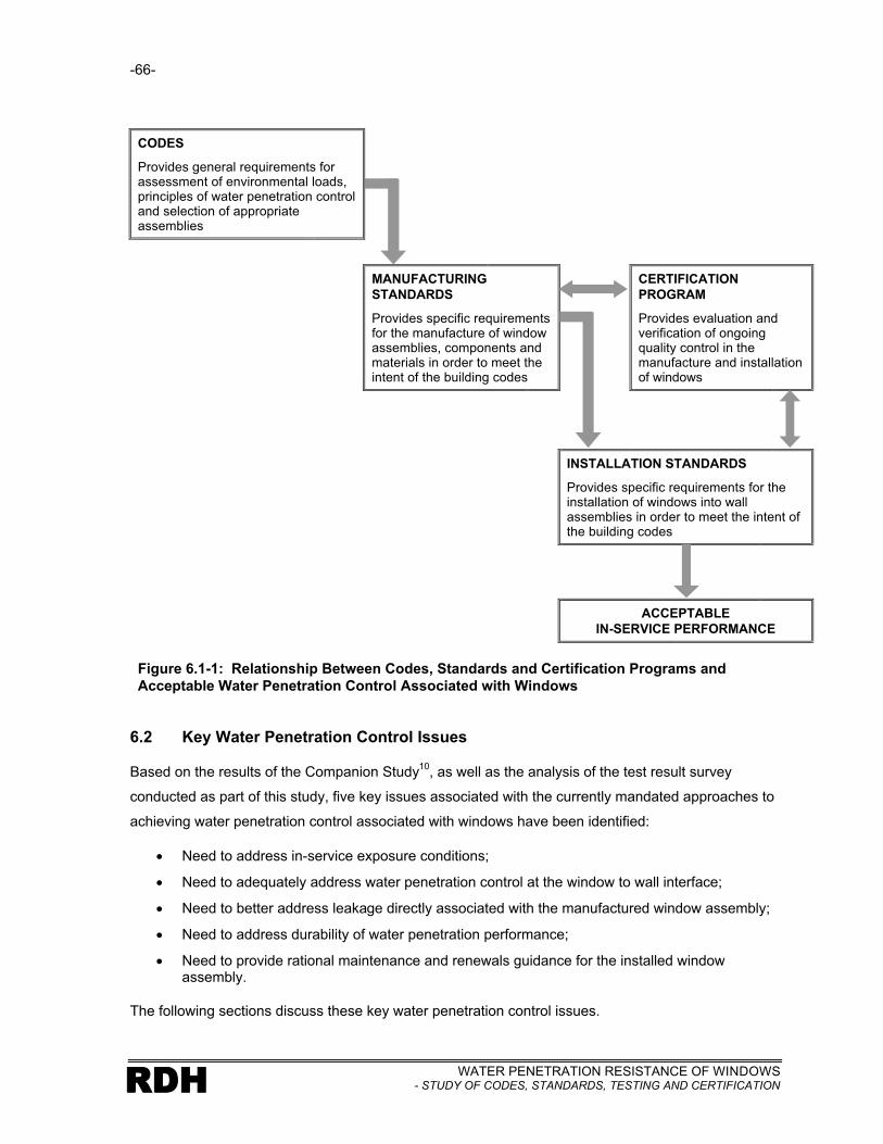
-66-
WATER PENETRATION RESISTANCE OF WINDOWS- STUDY OF CODES, STANDARDS, TESTING AND CERTIFICATIONRDH
CODES
Provides general requirements for assessment of environmental loads, principles of water penetration control and selection of appropriate assemblies
MANUFACTURINGSTANDARDS
Provides specific requirements for the manufacture of window assemblies, components and materials in order to meet theintent of the building codes
CERTIFICATIONPROGRAM
Provides evaluation and verification of ongoing quality control in the manufacture and installation of windows
INSTALLATION STANDARDS
Provides specific requirements for the installation of windows into wall assemblies in order to meet the intent of the building codes
ACCEPTABLEIN-SERVICE PERFORMANCE
Figure 6.1-1: Relationship Between Codes, Standards and Certification Programs and Acceptable Water Penetration Control Associated with Windows
6.2 Key Water Penetration Control Issues
Based on the results of the Companion Study10
, as well as the analysis of the test result survey
conducted as part of this study, five key issues associated with the currently mandated approaches to
achieving water penetration control associated with windows have been identified:
• Need to address in-service exposure conditions;
• Need to adequately address water penetration control at the window to wall interface;
• Need to better address leakage directly associated with the manufactured window assembly;
• Need to address durability of water penetration performance;
• Need to provide rational maintenance and renewals guidance for the installed window assembly.
The following sections discuss these key water penetration control issues.

-67-
WATER PENETRATION RESISTANCE OF WINDOWS- STUDY OF CODES, STANDARDS, TESTING AND CERTIFICATION RDH
6.2.1 In-Service Exposure Conditions
Consideration of exterior environmental conditions, or exposure, can be thought of in two regimes: a
peak exposure event (rainfall together with significant air pressure differential that can be expected to
occur relatively infrequently), and a standard in-service exposure event (rainfall with relatively low air
pressure differential and occurs frequently).
A requirement for a particular B level rating in a CSA A4407 mandated water penetration test will help
to ensure that the window is capable of resisting a peak event and is therefore significant in the
context of relatively infrequent wind driven rain. However, it is not clear that these ratings and the
associated testing have any significance with respect to the in-service performance of the installed
window. ‘Time of wetness’ is a concept that may be a more appropriate exposure criterion to consider
for the service life of the window.
Time of wetness is a significant variable with respect to water penetration performance and durability
because it is a measure of how often, and for what duration a window, and window to wall interface is
wet. Time of wetness is impacted by climate, building form, overhangs, and the local terrain and is
significant in every rainfall event.
Time of wetness impacts leakage paths that occur regardless of pressure differential due to wind
(primarily the driving force is gravity). In fact, much of the leakage activity of concern occurs at low or
no pressure differential. Time of wetness also becomes more significant as materials age because
the mere presence of water at a hole created by material aging can be a source of water penetration.
The most direct way to control time of wetness is through the provision of overhang protection (roofs,
balconies, flashing, rebates), with local topography having less significant effect.
The assessment of these micro exposure factors to determine a relative exposure category is not
currently well defined or supported by research. Certainly the significance of overhangs on wall
performance has been documented in The Survey1. An approach to assessing micro exposure
conditions has been presented in the Best Practice Guide12
and is reproduced in Figure 6.2-1.
Note that this nomograph was derived based on empirical evidence from coastal British Columbia. It
is likely conservative for other parts of Canada and could benefit from some refinement of the
procedure based on more quantifiable data related to time of wetness for different geographic
locations. However, it is believed that this model represents a reasonable starting point.

-68-
WATER PENETRATION RESISTANCE OF WINDOWS- STUDY OF CODES, STANDARDS, TESTING AND CERTIFICATIONRDH
Figure 6.2-1: Nomograph Relating Overhang Ratio and Local Terrain to Determine Micro-Exposure Conditions (Red indicates the assessment of low exposure conditions for a one storey house with 2’ roof overhangs)
It may be possible to introduce a micro-climate exposure factor into A440.18, based on the nomograph
in Figure 6.1-1, that dictates what minimum water penetration control strategy is required. For the low
exposure conditions depicted by the red line in Figure 6.1-1, a face seal window with relatively simple
window to wall interface details may provide acceptable performance. For higher exposure conditions
where the window will be regularly exposed to rain, reliable water penetration performance is best
achieved through a combination of a window that utilizes a rainscreen water penetration control
strategy, as well as a level of redundancy provided through the addition of sub-sill drainage.
0
0.1
0.2
0.3
0.5
0.4
A- Adjacent buildings of equal or greater height located within one building height in all directions
B- Many large buildings within 2 building heights
C- Rural areas, moderately treed, or buildings mostly fewer than 4 stories within 5 Building heights
D- Building located within 1km of direct waterfront exposure, or small or few surrounding obstructions, or located on a hill or cliff overlooking adjacent buildings
OverhangRatio
ExposureCategory
Terrain
Overhang Ratio = Overhang Width Wall Height
Where: Wall Height is the height above the lowest affected element(sill of window if considering a window)
Overhang Width is the horizontal distance between the outer surface of the cladding or window and the outer surface of the overhang

-69-
WATER PENETRATION RESISTANCE OF WINDOWS- STUDY OF CODES, STANDARDS, TESTING AND CERTIFICATION RDH
The selection of a particular water penetration control strategy can also have a significant impact on
the durability of water-tightness for given exposure conditions. This aspect of performance is
discussed in Section 6.2.3.
6.2.2 Window To Wall Interface Leakage
Failures at the window to wall interface is the dominant leakage problem associated with the in-service
window assembly. The field test results indicate that all leakage paths are significant, although based
on frequency of occurrence and risk of consequential damage, leakage through the window into the
adjacent wall assembly and through the window to wall interface to the adjacent wall assembly
present the greatest relative risk.
Clearly, while there is a need to create both a window and a wall assembly that are able to
accommodate the moisture loads imposed, the interface between these assemblies is equally
important. Unfortunately, it is not always clear how to effectively maintain continuity of critical moisture
control functions (critical barriers) through this interface. In addition, it is also not always clear what
parties are responsible for ensuring that continuity.
The term ‘Critical barrier’ refers to materials and components that together perform a specific function
within a wall or window assembly. All of these functions are ‘critical’ to the successful performance of
the assembly however, some of the functions are easier to achieve than others.
It is common to think of, and define, critical barriers within a wall assembly such as a vapour barrier or
air barrier. However, two additional barriers are also critical but less understood or used within the
industry. One of these critical barrier terms is the ‘water shedding surface’. The water shedding
surface refers to the surface of assemblies, interfaces and details that deflect and/or drain the vast
majority of exterior moisture (in the form of liquid water) impacting on the façade.
A second less well understood critical barrier term is the ‘exterior moisture barrier’ (it is also referred
to as a water resistive barrier). The exterior moisture barrier refers to the surface farthest into an
assembly from the exterior that can accommodate some exterior moisture (in the form of liquid water)
without causing damage to interior finishes or materials within the assemblies.
These four critical barriers can be used to describe an effective water penetration control strategy for
the window to wall interface as shown in Figure 6.2-2.
A key aspect of the detail shown in Figure 6.2-2 is the fact that both the window and the wall assembly
utilize a rainscreen water penetration control strategy. It is much easier to make a rainscreen
interface transition between two assemblies that also utilize this strategy. Conversely, it is often more

-70-
WATER PENETRATION RESISTANCE OF WINDOWS- STUDY OF CODES, STANDARDS, TESTING AND CERTIFICATIONRDH
difficult to achieve continuity through the window to wall interface when some incompatibility exists,
such as when a face seal window assembly meets a rainscreen wall assembly.
Critical Barriers:
Vapour Barrier
Air Barrier
Exterior Moisture Barrier
Water Shedding Surface
The four critical barriers can be used to describe the different moisture control functions within window and wall assemblies as well as at interfaces between window and wall assemblies. In this example the vapour barrier (resisting vapour diffusion) is provided by materials of low vapour permeability located near the interior of the wall and window assemblies and include the polyethylene sheet, window frame, and the interior sheet of glass.The air barrier function (resisting the flow of air in either direction) is provided by the drywall, seal to the sub-sill, seal between the sub-sill and the window frame, the window frame, the seal between the window frame and the glazing, and the glazing. The exterior moisture barrier function is provided by the glazing, the seal between the glazing and the window frame, the seal between the window frame and the sub-sill membrane, the sub-sill membrane, and the exterior sheathing paper. The water shedding surface function consists of the glazing, the glazing tape between the glazing and window frame, the exterior surface of the window frame, the sealant between the window frame and the sill drip flashing, the sill drip flashing and the exterior surface of thestucco cladding.
Figure 6.2-2: Continuity of Critical Barriers at Window to Wall Interface
Verification of performance of the window to wall interface is also necessary. Two key aspects of this
are quality assurance measures such as field review by the design and construction team, and water
penetration testing of the installed assembly. The ASTM E1105 testing protocol is appropriate for
testing the initial performance of this interface.

-71-
WATER PENETRATION RESISTANCE OF WINDOWS- STUDY OF CODES, STANDARDS, TESTING AND CERTIFICATION RDH
Field testing requirements need to be further developed. However, a useful starting point has been
provided in the BPG12
as follows:
Field-testing should be performed on large projects to assess the performance of the windows
and sliding doors prior to completing construction, thus allowing time for repairs to be
implemented. If the leakage through the test window is severe, or if it is difficult to repair,
additional testing should be performed in order to confirm the effectiveness of the remedial
repairs on the windows that have already been installed. Table 7.8 outlines the recommended
minimum test frequency for various size projects.
Table 7.8 Number of Recommended Field Tests
Number of windows
Prior to 5% Installed
At 50% installed
At 100% installed
0-25 0 0 0
25-100 1 0 0
100-200 2* 1 0
>200 3* 2 2
* At least one exposed sliding door if present.
Other factors must be considered in order to ensure durable service life performance however. These
issues are discussed in greater detail in Section 6.2.4.
6.2.3 Window Leakage
Despite the focus on the window to wall interface in Section 6.2.2, leakage activity directly through the
window continues to be a big issue. See Table 4.3-3. Of 215 leaks found in the field tests, 162 (75%)
occurred directly through the window assembly (leakage paths L1, L2, L4 & L6). While the argument
can be made that many of the windows tested had aged and may or may not have had appropriate
maintenance work undertaken, the results of the quality assurance testing during the initial
construction do not completely support this rationale. Figures 4.4-24 & 25 indicate a failure rate of
35% and 48% for combustible and non-combustible construction respectively. This means that new
windows can also experience significant leakage activity in a standard A4407 mandated test protocol.
The fact that some of the primary causal factors for leakage directly through windows are related to
conceptual design issues (poor balance between air tightness of gaskets and drainage at operable
vents, and limited by sill height), perhaps reflects either a lack of understanding of principles, or
conflict between desire to achieve high rating versus more costly long term performance (relatively
easy to achieve high B rating with perfect face seal, but difficult to achieve sustained acceptable
performance with a face seal strategy).
Window leakage is occurring at pressures well below the recommended B ratings. This reflects the
fact that appropriate ratings have historically not been mandated or specified, the fact that window

-72-
WATER PENETRATION RESISTANCE OF WINDOWS- STUDY OF CODES, STANDARDS, TESTING AND CERTIFICATIONRDH
components and materials have aged, and poor quality control. It likely also reflects a fundamental
lack of understanding of water penetration control principles as well as a lack of guidance on window
selection for durable performance.
The water penetration failure of the windows themselves suggests that additional steps need to be
taken to address design, quality control in manufacturing and window selection. The steps that can be
mandated through a combination of codes, standards and certification processes include:
• Mandate certification program that requires on-going water penetration testing and review of the manufacturing process for the manufactured window assembly
• Mandate appropriate water penetration control strategies for various exposure conditions
• Mandate field verification of performance
• Mandate requirements for provision of maintenance and renewals recommendations
6.2.4 Durability
It is possible to initially achieve acceptable water penetration performance of a manufactured window
(and even the window to wall interface) and then verify performance through testing. However, it is
the service life performance, not initial performance, which is the critical element of our water
penetration objectives for windows.
It is not practical to test for the durability of performance of installed windows, nor is it practical to test
all of the installed windows to ensure that they reliably meet the intended performance criteria. For
this reason measures must be incorporated into the design of the window and the window to wall
interface that provides confidence with respect to in-service performance. In addition to achieving
‘durability by design’, a mandated certification program that requires on-going testing of windows from
the manufacturing plant will help to ensure the reliability of the manufactured window product.
Durability by design involves the use of assemblies and details that incorporate some redundancy.
There is a need to incorporate some redundancy in design because all materials deteriorate with age
and it is not possible to build with perfection. An exception to this in the case of glazed assemblies
might be a Total Vision System (TVS) where the use of very durable materials, and simple design
provide acceptable long-term performance of what is essentially a face seal assembly. In addition,
TVS systems are generally easily accessible and maintainable. In practice however, residential
buildings dictate the use of more complicated combinations of materials and geometry that limit the
ability to achieve acceptable performance with face seal (no redundancy) assemblies and interfaces.
Even with complicated facades there are exceptions for certain exposure conditions. For example, a
poorly installed face seal window located in a protected environment such as under a balcony
projection or immediately beneath large roof overhangs will perform well with respect to water
penetration because it is rarely wetted.

-73-
WATER PENETRATION RESISTANCE OF WINDOWS- STUDY OF CODES, STANDARDS, TESTING AND CERTIFICATION RDH
Exterior Moisture Barrier Location for a Face Seal Window
Exterior Moisture Barrier Location for a Rainscreen Window
The term face seal describes a window where the water shedding surface is coincident with the exterior moisture barrier and air barrier.
The term rainscreen describes a window where the water shedding surface is not coincident with the exterior moisture barrier and air barrier. The exterior moisture barrier is located to the interior of the water shedding surface and there is an air space between the water shedding surface and the exterior moisture barrier that creates a capillary break. The flow of exterior moisture (rain) through the water shedding surface is minimized and the capillary break facilitates drainage of the minimal water that may penetrate past the water shedding surface into the cavities within the window frame. The exterior moisture barrier and air barrier are usually coincident in a rainscreen window.
Between these two categories (face seal and rainscreen) is a third category referred to as concealed barrier.Similar to the rainscreen approach, the water shedding surface is at a different location than the exterior moisture barrier. However, due to discontinuities in the water shedding surface, a poor air barrier, the lack of an air space between the water shedding surface and the exterior moisture barrier, poor pressure equalization characteristics or a combination of these variables, a more significant amount of water contacts and remains in contact with the exterior moisture barrier. The risk of water penetration for a well designed concealed barrier window (or wall) can fall somewhere between a face seal window (higher risk) and a rainscreen window (lower risk). However, the performance of concealed barrier windows can also be less effective than face seal windows. This is due to the fact that water can be retained inside the frame long after wetting events, and is in contact with sealants thereby adversely affecting the durability of the sealant due to constant water immersion. In addition, because water is sometimes retained within concealed spaces in the frame, frequency and quantity of water leakage through the frame can be more prevalent. The effective performance of concealed barrier windows is therefore dependent on the management of the variables described above (continuity of water shedding surface, location and continuity of air barrier, and drainage capability between the water shedding surface and the exterior moisture barrier).
Figure 6.2-3: Water Penetration Control Strategy for Windows
A rainscreen design strategy incorporates redundancy through the provision of an exterior moisture
barrier that is rarely wetted and is therefore more likely to provide good performance. See Figure 6.2-
3. Providing sub-sill drainage capability for a window essentially assumes that a window will leak at
some point in its service life and provides some redundancy through the provision of a second line of
resistance (See Figure 6.2-2). In fact, both rainscreen design and redundancy created by the use of
sub-sill drainage will help control water penetration at peak pressures also, while the initial
achievement of a particular B rating may have minimal relevance with respect to the long term water
penetration performance of a window or the window to wall interface.

-74-
WATER PENETRATION RESISTANCE OF WINDOWS- STUDY OF CODES, STANDARDS, TESTING AND CERTIFICATIONRDH
Some materials used in windows are inherently durable (such as appropriately coated aluminum, and
glass) while others such as sealants and coatings will require maintenance and renewals. However,
due to the location of windows on many buildings, access to address these maintenance and renewal
needs can be difficult. In addition, the location of some critical seals within a window unit and within
the window to wall interface are very difficult to replace or maintain in-service. Window selection and
detailing for durable water penetration control must therefore reflect reasonable maintenance and
renewals expectations.
6.2.5 Maintenance and Renewals
Window manufacturers and the design community have only recently acknowledged the need to
produce guidance for maintenance and renewals on a project by project basis. These plans are
essential, if effective performance is to occur throughout the service life of a window. In addition, the
plans are necessary so that the actual maintenance and renewals work is undertaken with a full
understanding of the assembly and its interface with the wall assembly, what work is critical for
performance, as well as the materials to used. The unique nature of an installed window in a
particular building means that the manufacturer of the window and those responsible for the selection
of the window and the design of the interface must be involved in preparing the maintenance and
renewals plan. As discussed in Section 6.2.3 the selection and design of windows and the window to
wall interface must reflect reasonable maintenance requirements. A requirement for the
manufacturers and designers to prepare plans will help to ensure that ‘reasonable plans are
developed. A sample of such a maintenance and renewals plan for a window-wall assembly is
provided in Appendix B.
There is need to mandate the preparation of these plans through codes and standards in order to
ensure that they are produced on a consistent basis.
6.3 Recommendations
The following sections summarize recommended changes to codes, manufacturing standards and
installation standards. Some of the proposed changes could benefit from further research. For
example, further research should be undertaken to better quantify ‘time of wetness’ for
different overhang ratios, orientations and geographic locations in Canada.
Guidance for the specification and selection of windows, as well as the design of the window to wall
interface is not currently consolidated. In addition, much of the knowledge gained through this study
and the Companion Study has not yet been incorporated in guidance documents. There is a need to
develop a ‘Best Practice Guide’ for windows that integrates all performance criteria.

-75-
WATER PENETRATION RESISTANCE OF WINDOWS- STUDY OF CODES, STANDARDS, TESTING AND CERTIFICATION RDH
6.3.1 Building Codes
Several of the issues identified in the previous sections of this report can be positively influenced by
changes to the applicable sections of building codes.
Part 5 of the code contains the requirements (expectations) for water penetration control. Part 9 goes
one step further by telling the user how to meet the performance expectations. The Appendix notes
are used to explain the requirements of Part 5 and Part 9. In addition, the Appendix can reference
other documents such as User Guides for additional information on how to meet the requirements. It
is in this context that the recommendations below are made.
Part 5
Include consideration of micro-exposure or ‘time of wetting’ as an environmental design
condition. At present the code provides a limited amount of information with respect to exposure
conditions through climatic tables. These tables and other sections within Part 5 do not provide
information related to micro-exposure conditions such as the impact of overhangs and local
topography. At the present time the various factors impacting ‘time of wetting’ and micro-exposure
are not well quantified. It is probably appropriate therefore that a requirement for consideration of
micro-climate effects be included within Part 5 itself, while the appendix note would describe in more
detail what is meant by micro-exposure effects and reference other guidance material with respect to
how to assess this factor. This note should include a discussion similar to that which is incorporated
into the BPG12
or within Section 6.2.2 of this report.
Provide guidance on selection of water penetration control strategy for particular micro-
exposure conditions. The code requirements should relate the determination of exposure category
or ‘time of wetness’ to the selection of an appropriate water penetration control strategy for
assemblies, components and details. In particular, the note could discuss the beneficial effects of
providing sub-sill drainage capability for windows since this one item potentially can have a significant
positive impact on water penetration control associated with windows. It should also discuss the need
to detail the window to wall interface so that it reflects the water penetration control strategy and
durability considerations for the adjacent wall assemblies.
Mandate consideration and disclosure of design service lives for assemblies, components and
materials used within the building envelope. A code requirement should be developed that
requires explicit consideration and disclosure of the intended durability expectations for building
envelope assemblies, components and materials. This will result in much better design decisions
being made. A mandate to consider durability can be achieved through a reference to CSA S478
Guideline to Durability in Buildings13
[S478], however there is a need to specifically mandate
disclosure of intended service lives within Part 5 in order to benefit fully from the consideration of
durability.

-76-
WATER PENETRATION RESISTANCE OF WINDOWS- STUDY OF CODES, STANDARDS, TESTING AND CERTIFICATIONRDH
Mandate the preparation of maintenance and renewals plans. As a corollary to the above
changes related to durability, there should be a requirement for preparation of a maintenance and
renewals plan that reflects the design service life expectancies of the assemblies, components and
materials. As this requirement is applicable to all aspects of the building (not just windows or the
building envelope) it may be better incorporated into the administrative sections of the codes.
Interestingly, if the preparation of maintenance and renewals plan is mandated, it may make the
requirement for disclosure of intended service lives a moot point since in order to develop a
maintenance and renewals plan, service lives must be explicitly considered and documented.
Part 9
Part 9 must reflect the same basic intent for performance expectations of windows as Part 5. Due to
the prescriptive nature of Part 9 however, this must be done in a more prescriptive manner. The use
of an overhang ratio as a single measure of micro-exposure conditions could simplify the
determination of appropriate water penetration control strategies. This coupled with appropriate
improvements and references to the A440 standards may be sufficient. For example, reference could
be made to the A440.49 Window Installation standard, which would in turn incorporate appropriate
requirements and details illustrating effective water penetration control strategies, and specific
requirements for materials, and components that would meet the intent for durability expectations.
6.3.2 Window Manufacturing Standards
Since the A440.07, A440.1
8 and NAFS
14 standards are fundamentally manufacturing standards, they
represent the key documents for initiating change to address the issues discussed in the previous
section and in the companion study with respect to manufacturing.
There is no appreciable difference between the water penetration control requirements of A4407 and
those contained in NAFS14
. The small test pressure differences that arise from the differing
calculation methods are not significant. However, it is in fact their similar failure to effectively address
several of the issues identified in this study that allow us to group them together in order to make
recommendations.
Create a classification system for windows that reflects their water penetration control
strategy. Neither the A4407 nor the NAFS
14 standard classifies windows in accordance with their
water penetration control strategy. While the task of determining the design intent for water
penetration control strategy is sometimes difficult it should be included as part of window
manufacturing standards in order to facilitate selection of windows that are appropriate for their in-
service exposure conditions.

-77-
WATER PENETRATION RESISTANCE OF WINDOWS- STUDY OF CODES, STANDARDS, TESTING AND CERTIFICATION RDH
Relate window water penetration control strategy to micro-exposure conditions. While NAFS14
does acknowledge that site and building specific exposure conditions can exist, there is no explicit
requirement for taking these factors into account when selecting a window. The quantification of
micro-climate effects is probably best left within the building codes, however, the process for selecting
an appropriate window for different exposure conditions should be included within the manufacturing
standards. It could be considered a parallel process used together with the traditional test pressure
criteria (B-ratings) to select appropriate windows.
Both A440.07 and NAFS
14 should describe and mandate a certification program to help ensure
reliability of the manufactured product. This may best be achieved through the development of a
separate standard for window certification that addresses manufacturing and installation issues. The
certification program should include many of the ‘strengths’ identified for the current programs and
add the following two elements:
• Requirement for installer training and certification
• Periodic requirement for retest of products pulled randomly from the plant
Manufacturers should be mandated to provide maintenance and renewals requirements for
their product. This information could then be used by the building designer to develop a
comprehensive maintenance and renewals plan for the entire building envelope.
6.3.3 Window Installation Standards
While improvements to the building codes and window manufacturing standards can establish an
appropriate context for decision making with respect to installation practices and details, there is a
need to mandate many of the good practice decisions in a window installation standard such as
A440.49.
The current A440.49 provides disproportionately little guidance with respect to water penetration
control and where guidance is included it is not well organized. A separate section needs to be
established that addresses rain penetration control. At present there is some good material titled
Rain Screen Method (section 6.6.11) contained within the section on Air tightness and a separate
section titled Weathertightness (section 6.7). Although there are requirements for sub-sill flashing
discussed, more guidance could be provided that relates specific methods of sub-sill drainage
to varying exposure conditions.
A requirement for testing of the window to wall interface and combination windows should be
added to the current standard. The lack of focus on these window perimeter issues may contribute
to the fact that many of the in-service water penetration problems are related to window perimeters.
Adding a requirement that typical perimeter conditions be tested may also encourage the development

-78-
WATER PENETRATION RESISTANCE OF WINDOWS- STUDY OF CODES, STANDARDS, TESTING AND CERTIFICATIONRDH
of extrusions that can be more effectively tied to the exterior moisture barrier and the water shedding
surface. For smaller buildings (Part 9) in low to medium exposure conditions the requirements for
testing could be waived if certain prescriptive installation methods and details are utilized.
In addition to the requirement for testing of window perimeter conditions, there is a need to involve
window manufactures in detailing of these interfaces. Adding a requirement for the manufacturer
to produce shop drawings that fully detail these interfaces will again focus their efforts on
reviewing how their products are being used and improving the details for their windows.
Details should be included within the standard that illustrate sound fundamental concepts or
principles for all functions that must be fulfilled by the window and window to wall interface.
For example, any details provided to illustrate water penetration control principles should also be
consistent with good detailing for air tightness and thermal issues. At present some of the details
illustrating air tightness principles will lead to water leakage at the window to wall interface for certain
exposure conditions. A well illustrated installation guide within the standard could draw on much of
the material developed and presented in the Companion Study10
graphical package including the
installation and field review checklist.
6.4 Summary
Achieving durable in-service water penetration performance of windows and at the window to wall
interface is a process of balancing peak and micro-exposure conditions, water penetration control
strategy, some redundancy in detailing, appropriate material selection, and reasonable maintenance
and renewal requirements. Verification testing and a certification program are also important
elements in ensuring quality throughout the process.
Table 6.4-1 presents the same roadmap as shown in Figure 6.1-1 that incorporates all of the key
elements of change noted in the previous sections.
RDH BUILDING ENGINEERING LIMITED

-79-
WATER PENETRATION RESISTANCE OF WINDOWS- STUDY OF CODES, STANDARDS, TESTING AND CERTIFICATION RDH
CODES
Provides general requirements for assessment of environmental loads, principles of water penetration control and selection of appropriate assemblies
MANUFACTURINGSTANDARDS
Provides specific requirements for the manufacture of window assemblies, components and materials in order to meet the intent of the building codes
CERTIFICATIONPROGRAM
Provides evaluation and verification of ongoing quality control in the manufacture and installation of windows
Ø Include consideration of micro-exposure or ‘time of wetting’ as an environmental design condition
Ø Provide guidance on selection of water penetration control strategy for particular micro-exposure conditions
Ø Mandate consideration and disclosure of design service lives for assemblies, components and materials used within the building envelope
Ø Mandate the preparation of maintenance and renewals plans
Ø Requirement for installer training and certification
Ø Periodicrequirement for retest of products pulled randomly from the plant
Ø Create a classification system for windows that reflects their water penetration control strategy
Ø Relate window water penetration control strategy to micro-exposure conditions
Ø Manufacturers should be mandated to provide maintenance and renewals requirements for their product
INSTALLATION STANDARDS
Provides specific requirements for the installation of windows into wall assemblies in order to meet the intent of the building codes
FURTHER RESEARCH
Ø Further research should be undertaken to better quantify ‘time of wetness’ for different overhang ratios, orientations and geographic locations in Canada
Ø There is a need to develop a ‘Best Practice Guide’ for windows that integrates all performance criteria
Ø A separate section needs to be established that addresses rain penetration control
Ø More guidance could be provided that relates specific methods of sub-sill drainage to varying exposure conditions
Ø A requirement for testing of the window to wall interface and combination windows should be added to the current standard
Ø Requirement for the manufacturer to produce shop drawings that fully detail these interfaces
Ø Details should be included within the standard that illustrate sound fundamental concepts or principles for all functions that must be fulfilled by the window and window to wall interface
ACCEPTABLEIN-SERVICE PERFORMANCE
Figure 6.4-1: Changes Required in Codes, Standards and Certification Programs to Help AchieveAcceptable Water Penetration Control Associated with Windows

-80-
WATER PENETRATION RESISTANCE OF WINDOWS- STUDY OF CODES, STANDARDS, TESTING AND CERTIFICATIONRDH

WATER PENETRATION RESISTANCE OF WINDOWS- STUDY OF CODES, STANDARDS, TESTING AND CERTIFICATION RDH
REFERENCES
1. Survey of Building Envelope Failures in the Coastal Climate of British Columbia, Canada Mortgage and Housing Corporation, 1996.
2. Study of Wall Moisture Problems in Alberta Dwellings, Canada Mortgage and Housing Corporation, 1999
3. Study of High-Rise Envelope Performance, Canada Mortgage and Housing Corporation, 2001
4. Glazing Design, Canadian Building Digest No. 55, Division of Building Research, National Research Council, 1964
5. Rain Leakage of Residential Windows in the Lower Mainland of British Columbia, Building Practice Note No. 42, Division of Building Research, National Research Council of Canada, 1984.
6. Rain Leakage in Wood Frame Walls: Two Case Histories, Building Research Note No. 210, National Research Council of Canada, 1984
7. Windows, CSA Standard A440-00, Canadian Standards Association
8. User Selection Guide to CSA A440-00, Windows, Special Publication A440.1, Canadian Standards Association
9. Window And Door Installation, CSA Standard A440.4-98, Canadian Standards Association
10. Water Penetration Resistance of Windows – Study of Manufacturing, Building Design, Installation and Maintenance Factors, Canada Mortgage and Housing Corporation, 2003
11. National Research Council of Canada, National Building Code of Canada 1995
12. RDH Building Engineering Limited & Morrison Hershfield Limited, Best Practice Guide – Wood Frame Envelopes In the Coastal Climate of British Columbia, Canada Mortgage and Housing Corporation, 2001
13. Guideline on Durability in Buildings, S478-95, Canadian Standards Association
14. North American Fenestration Standard – Voluntary Performance Specification for Windows, Skylights, and Glass Doors, 2002

WATER PENETRATION RESISTANCE OF WINDOWS- STUDY OF CODES, STANDARDS, TESTING AND CERTIFICATIONRDH
APPENDIX A
Sample Test Data Sheet

WATER PENETRATION RESISTANCE OF WINDOWS- STUDY OF CODES, STANDARDS, TESTING AND CERTIFICATION RDH
APPENDIX B
Sample Maintenance and Renewals Form


