
W A L T O N L O F T S W E S T E R N A V E & V I N E S T S E A T T L E , W A S H I N G T O N
E A R L Y D E S I G N G U I D A N C E J a n u a r y 8 , 2 0 1 3


WALTON LOFTS 01.08.2013 iii
TABLE OF CONTENTS
WALTON LOF TS EARLY DESIGN GUIDANCE
PROJECT TEAM ivDEVELOPMENT OBJECTIVES 1ZONING AND LAND USE SUMMARY 2SITE ANALYSIS 3STREETSCAPE 6BELLTOWN CHARACTER 13PRECEDENTS 17DESIGN GUIDELINE RESPONSE 21DESIGN EXPLORATIONS 24MASSING SCHEMES 26LANDSCAPE CONCEPTS 38DESIGN DEPARTURES 44
presented by
1809 SEVENTH AVENUE | SUITE 800S E A T T L E , W A 9 8 1 0 12 0 6 . 2 8 4 . 5 6 2 4w w w.v i a - a r c h i t e c t u r e . c o m

WALTON LOFTS 01.08.2013 iv
PROJECT TEAM
THE SCHUSTER GROUP
An award-winning design firm, VIA Architecture is one of the Pacific Northwest’s leaders in transit and urban design, and sustainable community planning. VIA currently employs 44 professionals in their Seattle, San Francisco, and Vancouver, BC offices. The firm is a compact organization focused on personal service for both public and private clients.
Through VIA’s design leadership role on large infrastructure projects, they have become adept at working in close collaboration with other design firms, the public sector, and transit agencies.
We listen. Our clients value the personal attention our team brings to each job, and our ability to create solutions that exceed their expectations. Through poetry + mathematics, we blend together function and beauty to solve problems in a thoughtful approach.
VIA ARCHITECTURE SHOESMITH COX
Kenneth Philp Landscape Architects (KPLA) is a firm of five dedicated practitioners who share a passion for landscape architecture, urban design, and sustainable development. Throughout the progression of a project, each site and situation generates ideas that are unique to themselves. KPLA prides itself on combining comprehensive site and context analysis with creativity to produce innovative, place-based spaces that not only serve immediate users, but are an asset to the wider community.
Our flexible, adaptable design approach allows us to address and respond to the complexities and opportunities of each project while maintaining the client and design team’s vision and goals. With this proven process and over 60 combined years of professional experience in planning, design, permitting, project management, and construction administration services, we are able to create places that are a unique expression of site and community.
LANDSCAPE ARCHITECT
Our design philosophy is based on listening, synergy and delight. By understanding the goals of the client – budgetary, market response and brand identity – as well as those of the City and other applicable stakeholders, we seek to create “win-win” situations. We look for opportunities available through the Design Review process to better the building’s envelope relative to the zoning code. We look for opportunities within the brand identity and market response to create fresh and delightful places that represent a unique offering – on the market and within the city. We deliberately seek to make the response spirited, delightful and fun. We seek to innovate and reach beyond previous work -- to learn from the past while pushing / pursuing new avenues of stimulation and creativity.
We deliberately seek to heal the fabric of the city and the immediate neighborhood in which a project resides. We look to make positive connections, to physical spaces and to the resonant perception of place. We look to understand how a building achieves the best possible “fit” – into both the context and the aspirations of its immediate community.
We strive to do all of this within an inclusive and collaborative environment. We seek to capture and nurture the creativity and passions of our clients, consultant teams and collaborators -- and harness these for the good of the project. We listen, think together, laugh and enjoy the successes of the entire team. We believe that great design is the product of strong individuals, but is also, at its most successful level, a team sport.
Established in 1989, The Schuster Group is a multi-faceted, vertically integrated real estate investment, development, and merchant banking firm, headquartered in Seattle, Washington.
As a nationally recognized award-winning developer, the Schuster name has become synonymous with innovation, sustainability, and assured quality. Throughout the years, The Schuster Group has built a distinguished reputation of developing dynamic environments by uniquely blending vision, creativity and high performance processes. Our experience extends across a wide array of real estate investments. From developing urban high-rise condominiums to revitalizing rural and suburban communities through housing, commercial office space and retail projects, The Schuster Group continues to change the landscape in which we do business and enhance the communities which bears our stamp through positive planning and development.
Paramount in our work is The Schuster Group mission: to serve our customers and stakeholders, by creating a legacy of distinctive sustainable building environments of value in which they will thrive.
There teams have worked together successfully on several projects in the past. Steve Cox of Shoesmith Cox Architects and VIA Architecture collaborated on the Joseph Arnold Lofts project (below), also for The Schuster Group and currently under construction. Steve was the Design Principal for The Schuster Group’s Mosler Lofts while with Mithun. Kenneth Philp Landscape Architects worked on Mosler Lofts, and collaborated with both Steve Cox and VIA Architecture personnel on the Thea’s Landing project in Tacoma.

WALTON LOFTS 01.08.2013 1
DEVELOPMENT OBJECTIVES
The Schuster Group is responsible for several of Seattle’s most innovative multi-family developments – from the acclaimed Mosler Lofts at Third Avenue and Clay Street to Muriel’s Landing on University Ave. and the Joseph Arnold Lofts, currently under construction at Elliott Avenue and Cedar Street. These projects begin with a commitment to their individual place in the city; to heal the fabric and create places of timeless quality and enduring value. This project will be no exception.
The project context is largely residential, across Vine Street, across Western Avenue and further to the north. The remainder of the block between this site and Wall Street to the south contains two 3-story commercial buildings, the Skyway Luggage building and another 3-story building housing the Millionaire Club.
The project seeks to develop 130-150 units of urban multifamily housing within this established residential neighborhood. The design seeks to respect its context, in both use and scale, and to offer an appropriate scale and presence relative to the neighborhood P-Patch Park immediately to the west across the alley. Underground parking is proposed for between 75 and 90 cars, and will be accessed from the alley.
Programmatically the building proposes to merge the building’s lobby and activity spaces into a “library” – offering programs available to building residents and guests and an attractive semi-public foyer buffering the resident spaces from the immediate context. The building plans to offer a fitness room, other activity spaces, a bike room and bike shop for resident use and a space adjacent to the P-Patch Park appropriate to use by P-Patch owners and gardeners. Between 2500 and 3500 SF of retail and /or other commercial uses along Western Avenue should support the sidewalk environment and provide pedestrian amenity and weather protection.
The primary building entry wants to be off Vine Street. Vine is perhaps Seattle’s most iconic “green street”, and we propose to continue established design vocabularies for this corridor as part of both the sidewalk design and that of the building’s northern edge. View corridor restrictions along Vine Street suggest a 25-foot step-back from Vine Street above a height of 35 feet.
Likely Design Departure requests include some relief from the view corridor restrictions, to permit the building to make appropriate setbacks in other areas. In addition we envision Design Departures for bay window design, marquee depth, (to permit and preserve street trees), lot coverage above 85 feet (to allow floorplate averaging and a simpler building), and vertical clearance at the alley.
Development Objectives + Program:
SITE
Western Ave
Elliott Ave
Vine S
t
Wall St
Denny Way
Broad
St
BelltownP-Patch

WALTON LOFTS 01.08.2013 2
ZONING & LAND USE SUMMARY
ZONE DMR/C 125/65 Belltown Urban Center Village Frequent Transit Service
SITE DATA Area = 14,400 SF (120’X120’) 2521 Western Ave Parcel Id: 0653000195
STREETS Vine Street - Green Street View Corridor Western Avenue - Principal Arterial, Class II Pedestrian Street
STRUCTURE HEIGHT SMC 23.49.008 C: 65’-0” for only non-residential or live work uses. 125’-0” For residential uses.
SMC 23.86.006 E: Height Measurement Vine Street slope is greater than 7.5%, property line divided into two equal segments (four or fewer required) none longer than 120’.
SMC 23.49.008 D: Above Height Limit Open Railing, Planters, Parapets - 4’-0” Stairs, Mech. Equipment - 15’-0” Elevator Penthouse For 8’ High Cab - 23’-0” For Taller Cabs - 25’-0” (elevator provides access to a rooftop providing 10’-0” usable open space)
SMC 23.49.008 D2: Roof Top Features Area Of Roof Features Above Base Height
STREET LEVEL USES SMC 23.49.009: No Requirement (Based On Street Designation)
COMMON RECREATION AREA SMC 23.49.010 B: 1. A total of 5% of the total gross floor area in residential use shall be provided as common recreation area and may be provided at or above ground level.
2. A maximum of fifty (50) percent of the common recreation area may be enclosed.
3. The minimum horizontal dimension for required common recreation areas shall be fifteen (15) feet, except for open space provided as landscaped setback area at street level, which shall have a minimum horizontal dimension of ten (10) feet. No required common recreation area shall be less than two hundred twenty-five (225) square feet.
4. Common recreation area that is provided as open space at street level shall be counted as twice the actual area in determining the amount provided to meet the common recreation area requirement.
9. For lots abutting designated green streets, up to fifty (50) percent of the common recreation area requirement may be met by contributing to the development of a green street.
FLOOR AREA RATIO SMC 23.49.011: In DMR/C zone, 125’/65’ Height District, Base Far is 1 and Max Far is 4.
Exemptions (SMC 23.49.011 B. 1.): b. Street level uses with 13’ floor height, 16’ depth and overhead protection. f. Residential use k. Below-grade floor area l. Parking accessory to residential use
Reductions (SMC 23.49.011 B.2) Mech Equipment Is 3.5% Reduction Of Chargeable Area After Exemptions
OVERHEAD WEATHER PROTECTION SMC 23.49.018: 10’ - 15’ above sidewalk minimum horizontal dimension of 8’ protection from building wall or 2’ from curb, whichever is less.
PARKING REQUIREMENTS SMC 23.49.019 A&B: No requirement; within structures, parking shall be below street level or separated by other uses 60% min medium size
SMC 23.49.019 H: Access to parking required to be from alley
BICYCLE PARKING SMC 23.49.019 B: 1 Bicycle parking space / 2 dwelling units. After 50, spaces additional spaces are required at one-half the ratio when covered auto parking is provided, all long-term bicycle parking shall be covered. Shower facilities for bicycle users is not required for residential occupancy.
SIDEWALK WIDTH REQUIREMENTS SMC 23.49.022: Minimum width of 12’ along Western Ave, variable width along Vine Street
VIEW CORRIDORS SMC 23.49.024: Minimum 25’ setback from Vine Street property line required above 35’ (measured at Western property line)
LOT COVERAGE SMC 23.49.158: 0’-65’ = 100% Coverage, 65’-85’ = 75% Coverage, 85’-125’ = 65% Coverage
FACADE TRANSPARENCY SMC 23.49.162 C&D: Western Ave Designation - Class II Pedestrian, S l o p e Of Street Frontage < 7.5% Required Façade Transparency = 30% Maximum Blank Façade = 30’-0’ Wide, 70% Total
Vine Street Designation - Green Street, Slope Of Street Frontage > 7.5% Required Façade Transparency = 25% Maximum Blank Façade = 30’-0” Wide, 75% Total.
SETBACKS SMC 23.49.166B: A. Side Setback: Not Required (<120’ Frontage Along Western Ave)
B. Green Street Setback: 10’ For Portions Above 65’ Up To 85’, Above 85’ Additional Setback At A Rate Of 1’ For Every 5’ Of Height.
MAXIMUM WIDTH AND DEPTH SMC 23.49.164: Height Of Portion Of Structure: 65’-125’: 90’ On Avenues, 120’ On East/West Streets
LOADING BERTH REQUIREMENTS SMC 23.54.035: No Requirement For Residential Uses
Key Zoning and Land Use Issues:

WALTON LOFTS 01.08.2013 3
SITE ANALYSIS
Zoning Map Existing Land Use Diagram
DMR/C 125/65
DH2/65
DH1/45
DMR/C 85/65
DMR/R 125/65
DMR/R 240/65
DMR/R 125/65
DMR/R85/65
Ceda
r St
Clay S
t
1st Ave
2nd Ave
Western Ave
Elliott Ave
Alaskan Way
Elliott Bay
Vine S
t
Wall St
Batte
ry St
SITE
Multi-Family
Terminal/Warehouse
Mixed-Use
Retail/Service
Office
Parking
Other Housing
Vacant
Park/Playground
Other
Government Service
Ceda
r St
1st Ave
Western Ave
Elliott Ave
Alaskan Way
Vine S
t
Wall St
Batte
ry St
SITE
N N

WALTON LOFTS 01.08.2013 4
SITE ANALYSIS
SITE SURVEY
0
5’ 25’
10’ 50’
The site is currently devoted to surface parking for about 45 cars. Accessed off the alley, the parking level is as much as 16 feet below the sidewalk elevation along Western Avenue. For purposes of this project we will assume Project North to be toward Vine Street, and the existing Millionair Club building to be immediately south of the site. The alley immediately west of the site is unpaved and largely unimproved. West of the alley is the Belltown P-Patch Park, devoted to public agricultural uses and the landmark-designated Belltown Cottages.
The site will need to “give” two feet along both the Western Avenue and alley frontages for R.O.W. width and improvements, although the building may step back over that setback at upper level(s). The adjacent Millionair Club’s building straddles the south property line about a foot, and will need to be underpinned in order to provide underground parking for this project.
Western Avenue
Vine
Str
eet
N
proj
ect N
orth

WALTON LOFTS 01.08.2013 5
SITE ANALYSIS
SITE CIRCULATION N
1st AveCe
dar S
t
Vine S
t
Wall St
Batte
ry St
Western Ave
Elliott Ave
Alaskan Way
City v
iews,
Mt. Rain
ier
Stadium, Duwamish,
West Seattle,
Puget Sound
Queen Anne,
Lake Union,
Space Needle
ViewsView Corridor
Green Street
Bus Route
Bus Stop
Elliott
Bay,
Olympic
Penin
sula 99
99
SUM
MER
SU
N P
ATH
WINTER SUN PATH
SITE
1st Ave
Ceda
r St
Vine S
t
Wall St
Batte
ry St
Western Ave
Elliott Ave
Alaskan Way
City v
iews,
Mt. Rain
ier
Stadium, Duwamish,
West Seattle,
Puget Sound
Queen Anne,
Lake Union,
Space Needle
ViewsView Corridor
Green Street
Bus Route
Bus Stop
Elliott
Bay,
Olympic
Penin
sula 99
99
SUM
MER
SU
N P
ATH
WINTER SUN PATH
SITE
N
Western Ave
Elliott Ave
Vine
St
Wall
St
Vehicles arriving from downtown and south/east of the project site must come down Wall Street, and turn right into the alley, then into the building. Vehicles coming south on Elliott Ave. may turn up Vine Street and enter the alley from the north, then into the building. Pedestrians arriving at the building will most likely walk down Vine Street or north along Western Ave until they find the building entrance. We believe a Vine Street address represents the better residential signature and identity for a building at this site.
WALTON LOFTS 01.08.2013 6
1st Ave
Ceda
r St
Vine S
t
Wall St
Batte
ry St
Western Ave
Elliott Ave
Alaskan Way
SITE
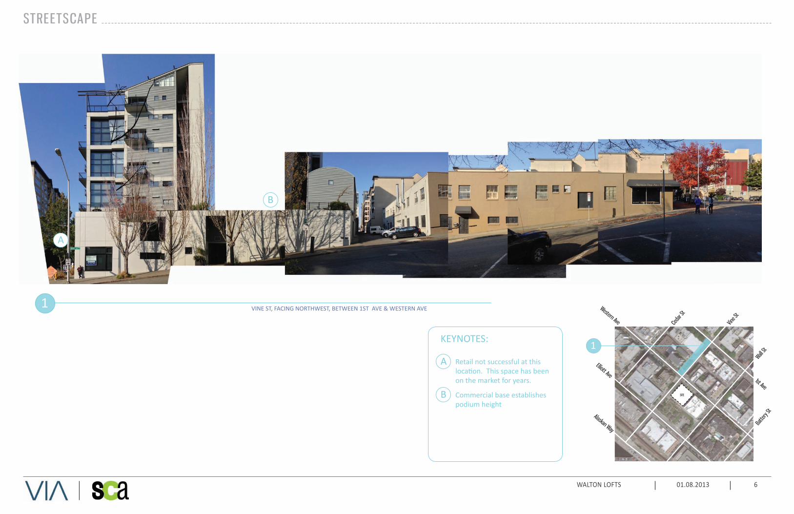
STREETSCAPE
1
1
VINE ST, FACING NORTHWEST, BETWEEN 1ST AVE & WESTERN AVE
A
KEYNOTES:
A
B
B
Retail not successful at this location. This space has been on the market for years.
Commercial base establishes podium height

WALTON LOFTS 01.08.2013 7
VINE ST, FACING NORTHWEST, BETWEEN WESTERN AVE & ELLIOTT AVE
STREETSCAPE
1
1st Ave
Ceda
r St
Vine S
t
Wall St
Batte
ry St
Western Ave
Elliott Ave
Alaskan Way
SITE1
A
KEYNOTES:
A
B
B
5-story parking structure is not an example of context we wish to emulate
Lower-than-prescribed podium/stepback at around 28 feet (relates to floor levels established for residential beyond)

WALTON LOFTS 01.08.2013 8
STREETSCAPE
1
1st Ave
Ceda
r St
Vine S
t
Wall St
Batte
ry St
Western Ave
Elliott Ave
Alaskan Way
SITE1
VINE ST, FACING SOUTHEAST, BETWEEN WESTERN AVE & ELLIOTT AVE2
2
VINE ST, FACING NORTHWEST, BETWEEN ELLIOTT AVE AND ALASKAN WAY
A
E B C D
KEYNOTES:
A Non-conforming 2-block-long building at 65-foot height (approximate)
B Historic Building as base, with residential above
C Note Vine Street address for residences
D Artistic interventions along Vine Street engage building, and vice-versa
E Non-conforming building at 65-foot height (approximate)

WALTON LOFTS 01.08.2013 9
STREETSCAPE
VINE ST, FACING SOUTHEAST, BETWEEN WESTERN AVE & ELLIOTT AVE
VINE ST, FACING SOUTHEAST, BETWEEN ELLIOTT AVE & ALASKAN WAY
1
2
1st Ave
Ceda
r St
Vine S
t
Wall St
Batte
ry St
Western Ave
Elliott Ave
Alaskan Way
SITE
2
1
C
A
B
KEYNOTES:
A Street/park design artistry and “cistern steps” story along edge of park
B Park is home to Belltown Cottages
C Largely-conforming building at 30-foot height (approximate)

WALTON LOFTS 01.08.2013 10
STREETSCAPE
1
1st Ave
Ceda
r St
Vine S
t
Wall St
Batte
ry St
Western Ave
Elliott Ave
Alaskan Way
SITE
WESTERN AVE, FACING NORTHEAST, BETWEEN VINE ST & CEDAR ST2
21
WESTERN AVE, FACING NORTHEAST, BETWEEN WALL ST & VINE ST
A
B
C D
E
B
KEYNOTES:
A Non-conforming building of uncertain height. “Good” example of a base/residential dialog.
B Less-positive example with street-level residential, planter screens and projecting bays
C Alluding to Banner Building one block to the north
D Podium ht. driven by residential levels and wood construction
E Iconic Banner Building (c.1994)with strong rhythm and rigorous articulation

WALTON LOFTS 01.08.2013 11
STREETSCAPE
1st Ave
Ceda
r St
Vine S
t
Wall St
Batte
ry St
Western Ave
Elliott Ave
Alaskan Way
SITE
12
WESTERN AVE, FACING SOUTHWEST, BETWEEN VINE ST & CEDAR ST
WESTERN AVE, FACING SOUTHWEST, BETWEEN WALL ST & VINE ST
1
2
A
B
DC E
KEYNOTES:
A Podium ht. driven by residential levels and wood construction
B Podium ht. driven by building’s internal logic, not context
C Skyway Luggage Building (vacant)
D Millionair Club Building
E Project site looking west

WALTON LOFTS 01.08.2013 12
STREETSCAPE
1
1st Ave
Ceda
r St
Vine S
t
Wall St
Batte
ry St
Western Ave
Elliott Ave
Alaskan Way
SITE
1
ELLIOTT AVE, FACING NORTHEAST, BETWEEN WALL ST & VINE ST
A
KEYNOTES:
B
Site (behind park) offers excellent views from all residential levels
Landmark-designated Belltown Cottages and P-Patch Park.
AB

WALTON LOFTS 01.08.2013 13
BELLTOWN CHARACTER
Belltown Cottages (archive photo)
Joseph Arnold Lofts (artist’s rendering) Mosler Lofts
Mosler Lofts along Cedar Street (green street w/ ground-level residential)
This design and development team has completed one project in Belltown -- Mosler Lofts at Third Avenue and Clay Street -- and is under construction with another, the Joseph Arnold Lofts project at Elliott Avenue and Cedar Street, one block north of this site. Both projects seek a “fit” within their context, and seek to fully realize their unique potential within Belltown’s urban fabric. Both previous projects utilized Design Departures available through the Design Review process to better the prescriptive zoning envelope for the benefit of their residents and their neighbors.
This project offers unique opportunities not available to the other projects – greater view potential and adjacency to the Belltown P-Patch Park. As such the building’s scale and design response will likely acknowledge this place, as well as the unique and special character of Vine Street.
Many of the images on the following pages come from the website of the Bell’s Town Tour -- “an opportunity to explore the history and culture of this vibrant neighborhood...”, sponsored by the City of Seattle Department of Neighborhoods, Belltown Business Association and its member businesses, and Michelle Hippler and Belltown Local.

WALTON LOFTS 01.08.2013 14
BELLTOWN CHARACTER
corner of Western and Vine
archive photo
entry along Vine Street
81 Vine Street Lofts, built 1914, renovated in 1994 and 1999 by Carolyn Geise
Long the home of Frayn Printing and Publishing, 81 Vine was renovated into a mixed-use building with offices, live/work lofts, a restaurant and parking. Seven additional penthouse units were constructed of metal siding, contrasting with the original brick structure. The bio-filtration system is disguised inside an exterior sculpture designed by artist Buster Simpson.
In addition to the iconic green street treatment and sculptural integration of a drainage strategy, this project informs the discussion of our desired parti’ -- that of a residential block over a site-filling masonry base.
The three-story base is very common in Belltown, and represents a key aspect of the “club” to which we seek to belong. The residential element above doesn’t try to copy or imitate the base, but separates itself in color, material and architectural expression. Some relationship between the two parts is pursued, primarily through the use of soft arch forms and transom lites.
guidance....

WALTON LOFTS 01.08.2013 15
BELLTOWN CHARACTER
Austin Bell Building. Note corner entry. Oregon Apartments, 1902 -- photo from Belltown Historic Tour website. Note corner entry.archive photo
Note the building/street relationship of the “new” building photo from Belltown Historic Tour website
Many of the simple three and four-story brick masonry buildings that once dominated Belltown are still around today.
Above and far right, the Hull Building, designed Elmer Fischer, 1889, 2401 First Ave. This Victorian style commercial building with touches of Richardsonian Romanesque, was built, in part, by Bing Crosby’s great-grandfather who worked as a carpenter during the construction. The striking brick façade is supported by cast iron columns and capped by a metal cornice. 1889 was the year Washington became a state and as well as the year a fire burned most of the city’s business district in Pioneer Square.
The scale of many of these buildings serves as a template for Zoning Code required stepbacks and podium height benchmarks in Belltown. This same height and experiential scale informed setback and stepback decisions at Mosler Lofts.
historical cues....

WALTON LOFTS 01.08.2013 16
BELLTOWN CHARACTER
Terminal Sales Building -- photo from Belltown Historic Tour website
photo from Belltown Historic Tour website note corner entry
photo from Belltown Historic Tour website
Buckley’s, housed in the MGM/ Loew’s Film Distribution Building, designed by Edmund W. Denle, 1936, 2331 Second
This one-story Art Deco building, also known as Majorie, originally housed the distribution center for two major studios. The building evokes 1930’s Hollywood glamour with its light colored brick contrasting with unusual black terra-cotta ornamentation. Belltown was home to almost two dozen buildings associated with “the talkies.”
In many ways this building serves as inspiration for the color palette we’re currently studying....
other examples....

WALTON LOFTS 01.08.2013 17
PRECEDENT EXAMPLES
Dominion Bank Center -- Mies van der Rohe
Dominion Bank Center -- Mies van der Rohe Glas Condominium Glas Condominium
Glas Condominium Glas Condominium -- note color and articulation of window wall / curtain wall
A recent research trip to Toronto yielded example projects that further inform our thinking as we enter the Schematic Design Phase of this project. The following illustrations highlight some of these areas….
The idea of contrasting a three and frour story masonry base with a simple, well-proportioned, dark metallic residential body is one we seek to pursue.
inspiration...

WALTON LOFTS 01.08.2013 18
PRECEDENT EXAMPLES
warm yellow brick and dark grey metal
warm grey brick
warm yellow brick in contrast to dark metal and glass
detail of brick detail of brick and dark metal
These buildings illustrate the color and material directions toward which we are leaning....connections...

WALTON LOFTS 01.08.2013 19
PRECEDENT EXAMPLES
mechanical vent decks
note concrete wall within unit
simple in-line kitchens that feel like furniture larger kitchen
raw materials without finishes or decorationThese elements further illustrate the project’s program and initial design intent.
The alley facade is not only the service side of the building and “back-of-house”, but it fronts directly on the park. Landscape treatments, innovative ways of handling mechanical screening and simple, sculptural approaches to those parts of the building that actively engage the park (decks, operable windows, rooftop terraces, etc.) can help to minimize the intrusion.
The units themselves plan to offer simple, open and flexible plans and generous windows -- effectively making the city and the views into the fourth wall of every room. Use of raw concrete at walls and ceilings further expresses the building’s connection to the reality and enduring structure of urban life.
elements...

WALTON LOFTS 01.08.2013 20

WALTON LOFTS 01.08.2013 21
A-1 RESPOND TO THE PHYSICAL ENVIRONMENT
Develop an architectural concept and compose the building’s massing in response to geographic conditions and patterns of urban form found beyond the immediate context of the building site.
The building will be organized to optimize views, utilize the natural topography and support the human and vehicular circulatiuon patterns of the neighborhood.
A-2 ENHANCE THE SKYLINE
Design the upper portion of the building to promote visual interest and variety in the downtown skyline.
B-1 RESPOND TO THE NEIGHBORHOOD CONTEXT
Develop an architectural concept and compose the major building elements to reinforce desirable urban features existing in the surrounding neighborhood.
B-2 CREATE A TRANSITION IN BULK & SCALE.
Compose the massing of the building to create a transition to the height, bulk, and scale of development in neighboring or nearby less intensive zones.
The building proposes to step back in acknowledge-ment of surrounding buildings and open space.
B-4 DESIGN A WELL-PROPORTIONED & UNIFIED BUILDING
Compose the massing and organize the publicly accessible interior and exterior spaces to create a well-proportioned building that exhibits a coherent architectural concept. Design the architectural elements and finish details to create a unified building, so that all components appear integral to the whole.
While the building proposes to have a distinct base and “body”, the two will be woven together through secondary elements, common proportions
and other unifying elements.
C-1 PROMOTE PEDESTRIAN INTERACTION
Spaces for street level uses should be designed to engage pedestrians with the activities occurring within them. Sidewalk-related spaces should be open to the general public and appear safe and welcoming.
C-3 PROVIDE ACTIVE - NOT BLANK - FACADES
Buildings should not have large blank walls facing the street, especially near sidewalks.
We propose to average floor areas above the podium level, permitting more setbacks and window area below 65 feet than would be possible under a strict zoniong code response.
C-4 REINFORCE BUILDING ENTRIESTo promote pedestrian comfort, safety, and orientation, reinforce the building’s entry.
We propose the building entry on the corner of Western and Vine, and a Vine Street (green street) address.
C-5 ENCOURAGE OVERHEAD WEATHER PROTECTION
Encourage project applicants to provide continuous, well-lit, overhead weather protection to improve pedestrian comfort and safety along major pedestrian routes.
C-6 DEVELOP THE ALLEY FACADE
To increase pedestrian safety, comfort, and interest, develop portions of the alley facade in response to the unique conditions of the site or project.
We anticipate that the alley facade will be among the most prominently viewed sides of the building, and will treat it as such.
D-2 ENHANCE THE BUILDING WITH LANDSCAPING
Enhance the building and site with substantial landscaping—which includes special pavements, trellises, screen walls, planters, and site furniture, as well as living plant material.
We propose to spend considerable time and attention on this aspect of the building/site design.
D-3 PROVIDE ELEMENTS THAT DEFINE THE PLACE
Provide special elements on the facades, within public open spaces, or on the sidewalk to create a distinct, attractive, and memorable “sense of place” associated with the building.
E-1 MINIMIZE CURB CUT IMPACTS.
Minimize adverse impacts of curb cuts on the safety and comfort of pedestrians.
E-2 INTEGRATE PARKING FACILITIES
Minimize the visual impact of parking by integrating parking facilities with surrounding development. Incorporate architectural treatments or suitable landscaping to provide for the safety and comfort of people using the facility as well as those walking by.
Parking and service functions will occur within the building, will be accessed off the alley, and be shielded from the park and the public.
E-3 MINIMIZE THE PRESENCE OF SERVICE AREAS.
Locate service areas for trash dumpsters, loading docks, mechanical equipment, and the like away from the street front where possible. Screen from view those elements which for programmatic reasons cannot be located away from the street front.
Parking and service functions will occur within the building, will be accessed off the alley, and be shielded from the park and the public.
PERTINENT DESIGN GUIDEL INES

WALTON LOFTS 01.08.2013 22
BELLTOWN-SPECIF IC DESIGN GUIDEL INES
While ours is a standard-sized and traditionally-shaped lot, we do enjoy some unique characteristics. The site slopes about 16 feet down to the west (toward the alley and the P-Patch Park), presenting access and frontage challenges along the Vine Streetscape.
Vine Street represents a further challenge in that it is perhaps Seattle’s most iconic “green street”. Vine St. offers quirky and unique artistic elements, glorifying the mundane and delighting the pedestrian. The P-Patch Park at Vine St. and Elliott, immediately west of the site, houses the historic Belltown Cottages and represents another whimsical and individualistic expression of Vine Street’s singular DNA.
This is a view site -- offering excellent views to the southeast (city and territorial), to the south (downtown and skyline), to the southwest (stadiums, Port of Seattle, Duwammish waterway, cranes) and to the west and northwest (Elliott Bay, shipping lanes, islands ands mountains).
We propose to take scale and material cues from adjacent buildings, as well as to offer scale and/or material transitions designed to create an appropriate and humane scale relative to the park.
To a significant degree, the sketch at left labeled “INSTEAD...” is representative of the building parti we prefer. We propose a 3 and 4-story masonry base, and to set the “tower” portion of the building away from that in both distance and expression.
We’ve shown examples of the “club” to which we seek to belong.
We propose a 3-story “podium” of masonry, respecting this historical and physical context, and a simple 8-story rectangular block atop that base.

WALTON LOFTS 01.08.2013 23
BELLTOWN-SPECIF IC DESIGN GUIDEL INES
We propose to respect the unique streetscape along Vine through landscape and hardscape treatments unique to this project.
We propose a corner entry, at Western and Vine, and a Vine Street address.
We propose amenity and semi-public spaces along Vine Street, encouraging and supporting interaction between inside and outside along this frontage.
We recognize that this zone of Western Avenue is NOT a strong retail concentration, and propose street-level residential uses along a portion of this frontage.
We recognize the alley frontage as more than the back of the building -- but another “front” along which service and access must occur.
We seek to locate vehicular entries so as to minimize traffic and conflicts along the park’s alley frontage.

WALTON LOFTS 01.08.2013 24
DESIGN EXPLORATIONS
BASE ZONING ENVELOPE:
100% Lot Coverage 0-65’
75% Lot Coverage 65’-80’
65% Lot Coverage 85’-125’
25’ View Corridor setback from Vine above 35’
AVERAGE:
Floorplates above view corridor averaged for simplicity, constructability, and design clarity
Permits additional south wall articulation
Departures:
Floor area above 85’
possibly: window bays
AVERAGE HI -L INE HI -L IF T :
View corridor stepback level raised two stories to create additional open-ness and a “civic scale” at ground plane
Floorplates above view corridor averaged for simplicity, constructability, and design clarity
Permits additional south wall articulation
Departures:
Floor area above 85’
View corridor (height and width)
possibly: window bays
A L IT TLE SHIF T :
Similar to “GOOD SOUTH WALL” scheme....
SE corner echoes splay - reinforcing stepback from central piece
Departures:
Floor area above 85’
View corridor (height)
possibly: window bays
AVERAGE HI -L INE :
View corridor stepback level raised one story to create open-ness at ground plane
Floorplates above view corridor averaged for simplicity, constructability, and design clarity
Permits additional south wall articulation
Departures:
Floor area above 85’
View corridor (height)
possibly: window bays
GOOD SOUTH WALL :
View corridor stepback level raised one story to create open-ness at ground plane
South wall pushed back 6’-14’ from property line to allow glazing
NE corner pulled into view corridor, creating splayed wall
Floorplates above view corridor averaged for simplicity, constructability, and design clarity
Departures:
Floor area above 85’
View corridor (height)
possibly: window bays
This scheme represents one possible interpretation of the base zoning envelope, with stepbacks at the heights prescribed.
Note the extent of blank, south-facing (city-facing) wall below 65 feet where lot coverage remains at 100%. Even to the 85-foot height, window areas are reduced below a practical level.
Schemes studied, learned from and, in most cases, rejected....
This scheme also represents a similar square footage yield, but sets the upper-story mass of the building to the north a bit -- allowing more glazing at the south wall facing downtown. This scheme also proposes a splay in the north wall, to minimize the impact of the upper portion’s move into the view corridor.
This scheme also represents a similar square footage yield, but sets the upper-story mass of the building to the north a bit -- allowing more glazing at the south wall facing downtown. This scheme also proposes a splay in the north wall, to minimize the impact of the upper portion’s move into the view corridor.
This scheme represents a similar overall square footage as the base zoning scheme, but requires fewer different floor plate configurations.
This scheme lifts the podium and the view corridor stepback up one story to create open spce and a view corridor at the (Western Avenue) sidewalk level. This scheme also informs and influences many of those following, exploring the idea of raising the podium base along the view corridor / green street edge in order to provide public space (at the Western Avenue elevation) along it. Re-connection with the street at the NW corner of the site is problematic for these schemes....
This scheme lifts the podium and the view corridor stepback up yet another story into the view corridor -- and is perhaps a little too “heroic”.

WALTON LOFTS 01.08.2013 25
DESIGN EXPLORATIONS
PODIUM - ALTERNATIVE 1 :
Floorplates above view corridor averaged for simplicity, constructability, and design clarity
Building/base dialogue in favor of scale relative to context, scale relative to P-Patch park
Permits additional south wall fenestration
Departures:
Floor area above 85’
View corridor (width)
PODIUM - ALTERNATIVE 2 :
Floorplates above view corridor averaged for simplicity, constructability, and design clarity
Building/base dialogue in favor of scale relative to context, scale relative to P-Patch park
Permits additional south wall fenestration
Departures:
Floor area above 85’
View corridor (width)
PODIUM - ALTERNATIVE 3 :
Floorplates above view corridor averaged for simplicity, constructability, and design clarity
Building/base dialogue in favor of scale relative to context, scale relative to P-Patch park
Permits additional south wall fenestration
Departures:
Floor area above 85’
View corridor (width)
Window bays
BUMP CITY (WWBD):
View corridor stepback level raised one story to create open-ness at ground plane
Transparent bays into view corridor along NW face of building offer planting, articulation and green street response
Floorplates above view corridor averaged for simplicity, constructability, and design clarity
Departures:
Floor area above 85’
View corridor (height and width)
Window bays
GREEN WALL :
View corridor stepback level raised one story to create open-ness at ground plane
Green street view corridor response
Floorplates above view corridor averaged for simplicity, constructability, and design clarity
Departures:
Floor area above 85’
View corridor (height and width)
Window bays
BOOKSTACK:
View corridor stepback level raised one story to create open-ness at ground plane
Transparent bays into view corridor along NW face of building offer planting, articulation and green street response
Floorplates above view corridor averaged for simplicity, constructability, and design clarity
Departures:
Floor area above 85’
View corridor (height and width)
Window bays
This scheme, affectionately referred to as “What Would Buster Do” offers a whimsical composition of mostly-transparent, green-roofed intrusions into the view corridor.
The rooftop massing illustrated in these past several schemes is also less than ideal for several reasons....
This scheme, also known as “What Would Koolhas Do” offers a celebratory extrapolation of the lobby’s “library” space while highlighting the diversity of the site’s view opportunities. (It is not a legitimate option for us.)
This scheme proposes to echo the green-street/view corridor setback with a sculptural element within the view corridor.
Pulling the upper-level mass tof the building to the north enough to permit south-wall glazing, this scheme sets a simple rectangular element atop a simple square one.
Similar to the previous scheme, this option splays the north wall such that the northwest corner most critical to the function of the view corridor may intrude to a lesser degree.
This scheme proposes less intrusion into the view corridor, but offers no stepback from the podium above the park.

WALTON LOFTS 01.08.2013 26
BUILDING MASSING SCHEME 1 - CODE COMPLIANT OPTION
Notes:
• 100% Lot Coverage 0-65’
• 75% Lot Coverage 65’-85’
• 65% Lot Coverage up to 85’-125’
• 25’ View Corridor setback from Vine above 35’
Departures:
• None Required
View corridor - Vine & 2nd Ave
View corridor - Vine & 1st Ave
Looking up WesternLooking up WesternLooking up Western

WALTON LOFTS 01.08.2013 27
Looking up WesternLooking up WesternLooking up Western
View corridor - Vine & 2nd Ave
View corridor - Vine & 1st Ave
Notes:
• floorplates above view corridor averaged for simplicity, constructability, marketing consistency and design clarity
• building / base dialog in favor of scale relative to context, scale relative to P-Patch park
• permits additional south wall fenestration
Departures:
• floor area above 85’
• bay window
BUILDING MASSING SCHEME 2

WALTON LOFTS 01.08.2013 28
PROPOSED AREA ADDED TO EXISTING ZONING ENVELOPE
PROPOSED AREA REMOVED FROM EXISTING ZONING ENVELOPE
BUILDING MASSING SCHEME 2

WALTON LOFTS 01.08.2013 29
BUILDING MASSING SCHEME 2
2’
WESTERN AVENUEVI
NE S
TREE
T
GROUND LEVEL - L2
A A
VIEW
CO
RRID
OR
SETB
ACK
10’
25’
23’
2’
23’ 10’
25’
VIEW
CO
RRID
OR
SETB
ACK
L3-4 L5-1 1
L 12
A A A A
A A
PROGRAM LEGENDRESIDENTIAL
VERTICAL CIRCULATION
CIRCULATION
SUPPORT
AMENITY
B
B
B
BB
B
B
BALLEY
N
proj
ect N
orth

WALTON LOFTS 01.08.2013 30
SECTION A-A SECTION B-B
PLPL
ROOF LEVEL
LEVEL 12
LEVEL 11
LEVEL 10
LEVEL 9
LEVEL 8
LEVEL 7
LEVEL 6
LEVEL 5
LEVEL 4
LEVEL 3
LEVEL 2
LEVEL 1.5
LEVEL 1
LEVEL P1
BUILDING MASSING SCHEME 2
PL PL
ROOF LEVEL
LEVEL 12
LEVEL 11
LEVEL 10
LEVEL 9
LEVEL 8
LEVEL 7
LEVEL 6
LEVEL 5
LEVEL 4
LEVEL 3
LEVEL 2
LEVEL 1.5
LEVEL 1
LEVEL P1
VIEW
CO
RRID
OR
SETB
ACK
25’
23’
10’
35’
Min
.

WALTON LOFTS 01.08.2013 31
BUILDING MASSING SCHEME 3 - PREFERRED
Notes:
• floorplates above view corridor averaged for simplicity, constructability, marketing consistency and design clarity
• building / base dialog in favor of scale relative to context, scale relative to P-Patch park
• permits additional south wall fenestration
Departures:
• floor area above 85’
• view corridor (width)
View corridor - Vine & 2nd Ave
View corridor - Vine & 1st Ave
Looking up WesternLooking up WesternLooking up Western

WALTON LOFTS 01.08.2013 32
BUILDING MASSING SCHEME 3 - PREFERRED
PROPOSED AREA ADDED TO EXISTING ZONING ENVELOPE
PROPOSED AREA REMOVED FROM EXISTING ZONING ENVELOPE

WALTON LOFTS 01.08.2013 33
VIEW
CO
RRID
OR
SETB
ACK
20’ 10’
4’
25’
2’
2’
VIEW
CO
RRID
OR
SETB
ACK
20’ 10’
4’
25’
WESTERN AVENUE
ALLEY
VINE
STR
EET
the “ l ibrary”
GROUND LEVEL - L2
L3-4 L5-1 1
L 12
A A
A A
A A
A A
PROGRAM LEGENDRESIDENTIAL
VERTICAL CIRCULATION
CIRCULATION
SUPPORT
AMENITY
B
B
B
B
B
B
B
B
BUILDING MASSING SCHEME 3 - PREFERRED
The amenity space immediately west of the entry notch is the “library” -- a multi-purpose, multi-functional space offering information kiosks, reading and gathering spaces, a literature collection, digital media, television and coffee for residents and guests. The space connects to the lobby, and visually connects Western Avenue and the view of Elliott bay.
N
proj
ect N
orth

WALTON LOFTS 01.08.2013 34
SECTION A-A SECTION B-B
PLPL
ROOF LEVEL
LEVEL 12
LEVEL 11
LEVEL 10
LEVEL 9
LEVEL 8
LEVEL 7
LEVEL 6
LEVEL 5
LEVEL 4
LEVEL 3
LEVEL 2
LEVEL 1.5
LEVEL 1
LEVEL P1
4’
PL PL
ROOF LEVEL
LEVEL 12
LEVEL 11
LEVEL 10
LEVEL 9
LEVEL 8
LEVEL 7
LEVEL 6
LEVEL 5
LEVEL 4
LEVEL 3
LEVEL 2
LEVEL 1.5
LEVEL 1
LEVEL P1
VIEW
CO
RRID
OR
SETB
ACK
25’
20’
10’
35’
Min
.
BUILDING MASSING SCHEME 3 - PREFERRED

WALTON LOFTS 01.08.2013 35
BUILDING MASSING SCHEME 3 - PREFERRED: PARTI DIAGRAM / DESIGN ISSUES
Diagrammatically this scheme proposes to place a 7 to 8 story rectangular block atop a 3 to 4 story square one. The square (masonry) block “belongs” to the site and its resonant Belltown context; the rectangular one belongs to the view. It seeks the simplest elegant solution, while weaving elements of this upper mass through the frames of the lower one.
Design issues critical to the best realization of this simple scheme include clarity of the podium mass, the averaging of floor plates above the podium level, setback of the upper mass for windows and views, and integration of the rooftop amenity and mechanical screening elements.
We see the pulling back of the upper mass at the western side (park edge) of the podium as beneficial to reinforcing the separation of these two masses and to the perceived scale of the building relative to the park.
We see bikes entering and exiting near the alley and Vine Street, people (pedestrians) entering and exiting near the Vine and Western corner and cars entering and exiting toward the south end of the alley. We see the “library” amenity space all along the Vine Street edge, from the entry lobby to the alley side -- and offering views through to the mountains and Elliott Bay.
We see residential uses along the Western Avenue street frontage as a better offering than retail ones, as this neighborhood has not supported smaller-scale street-level retail uses in the recent past.
We love this site.N
proj
ect N
orth

WALTON LOFTS 01.08.2013 36
BUILDING MASSING SCHEME 3 - PREFERRED
View southeast on WesternView southwest on Vine
View north from Elliott View northeast from Elliott & Vine
View northwest on Western

WALTON LOFTS 01.08.2013 37
BUILDING MASSING SCHEME 3 - PREFERRED: SOLAR STUDY
SUM
MER
SO
LSTI
CE
3 P M
3 P M
3 P M
N O O N
N O O N
N O O N
9 A M
9 A M
9 A M
EQU
INO
XW
INTE
R S
OLS
TIC
E

WALTON LOFTS 01.08.2013 38
PEDESTRIAN CIRCULATION AND PARTI DIAGRAM
CONCEPTThe landscape partí is composed of overlapping bands, each band reflecting a distinct element critical to informing the site design and how it responds to its surroundings. These components include the historic context of the site and neighborhood, the movement and celebration of rainwater, and the implementation of Green Street principles. Interweaving these conceptual elements to gradually and seamlessly mix will help reinforce a sense of place, enhance the pedestrian experience, and stitch together what is now a void in the urban fabric while creating another successful connector within the Green Streets model.
CIRCULATIONUnderstanding pedestrian patterns and circulation is critical to the success of the design concept.
WESTERN AVENUE
ELLIOTT AVENUE
VIN
E ST
REET
WAL
L ST
REET
LEGEND PRIMARY NODE STREET CROSSING
SECONDARY NODE SIDEWALK 1
2
3
4
5
6
KEY NOTES HISTORICAL CONTEXT, INTERPRETIVE AND WAYFINDING ELEMENTS
STREETSCAPE PLANTED EDGE PEDESTRIAN NODE, GREEN STREET, WAYFINDING
GREEN STREET, RAINWATER CELEBRATION, HISTORICAL CONTEXT, LIVING WALLS
GREEN STREET, P-PATCH COMMUNITY CONNECTION, LIVING WALLS
LIVING WALLS, ALLEY PAVEMENT TREATMENTS, P-PATCH COMMUNITY CONNECTIONS
123
4
5
VIEW
CO
RRID
OR
WESTERN AVENUE
VIN
E ST
REET
BELLTOWN P-PATCH
6

WALTON LOFTS 01.08.2013 39
1
2
3
4
5
6
3
4
5
VIEW FROM CORNER OF VINE STREET AND WESTERN AVENUE
VIEW FROM VINE STREET AND ALLEY
Surrounded by a rich historic context with several architectural landmarks still present, this site has countless stories to tell. Through use of interpretive design elements in the streetscape, there is an opportunity to reveal and illuminate this past. Just as a dramatic alteration of topography during the Denny Re-grade created what is now Belltown, the future will bring equal transformation to the urban fabric by way of changes like the Seawall replacement project and removal of the Viaduct. By incorporating the strongest historic elements and interweaving those with demonstrations of sustainable practices, Walton Lofts will reinforce the Green Street model already shaping this neighborhood.
The streetscape should respond to and feel connected with the site’s surroundings. This can be accomplished in a number of ways, such as using the building’s materials in the horizontal plane and creating pedestrian-scaled sidewalk spaces that relate to the adjacent streetscapes. These relationships are especially critical along Western Avenue, where there is fast-moving traffic and little evidence of interventions that make for a comfortable pedestrian environment. This frontage provides opportunity creating a space that will be the beginning of a pedestrian-level reconnection of this area to the larger Belltown and Downtown communities, a connection that we hope becomes stronger with current and future urban design efforts. For those approaching from the south along Western, the hardscape-oriented streetscape will begin to give way to a softer, more open space. The topography, water views, and access to light make this corner ideal for creating an inviting public streetscape that could include design components such as rainwater demonstrations, native plantings, and artistic interpretive or wayfinding elements.
From an urban design perspective, the corner of Western Avenue and Vine Street will serve as the building’s primary entrance, and will therefore be a critical pedestrian node. In addition, the topography here affords unique prospect, which makes this a highly visible and important space. From a story-telling perspective, this intersection is a convergence of natural elements and urban history; it is here where you take in expansive views of Elliott Bay—the ultimate destination of the rainwater that falls here—as well as the Belltown Cottages and historic brick buildings.
Descending from east to west along Vine Street, pedestrians’ progress from a very urban environment into this visibly unique and special part of Belltown is punctuated by views down to the p-patch and cistern steps. The steep topography and precedent of other Green Street elements creates a setting where the presence or demonstration of the movement of stormwater along the north building façade may gradually give way to vertical planting or live walls. In keeping with the most successful elements of the adjacent Vine Street streetscape, articulation of sidewalks, use of native plantings, and celebration of rainwater will be part of the Walton Lofts landscape vocabulary.
The nature of the historic cues, as well as the scale of the pedestrian environment, changes dramatically as you move from urban-historic (north side) to residential-historic (west side) of the building. This results in the introduction of new colors and textures that are unique to both Belltown and the greater Downtown area. With the topography and adjacencies to the Belltown P-Patch and cistern steps, water movement and rainwater catchment will continue to inform the landscape design, though the character and type of rainwater demonstration may begin to reflect the unique spirit of the p-patch. This finer-grained urban-agrarian context elicits a different design response that will connect and bridge the more urban-facing parts of the building. Here, integrating historic interpretive elements, living walls or other vertical green components, and paving systems and patterns reaching across the alley will help create an appropriate ‘front’ to our western neighbors.
LANDSCAPE PARTI & NARRATIVE

WALTON LOFTS 01.08.2013 40
Paving Materials & Patterns
Historic & Interpretive Elements
LANDSCAPE PRECEDENTS / INSPIRATION

WALTON LOFTS 01.08.2013 41
LANDSCAPE PRECEDENTS & INSPIRATION
RAINWATER & STORM DRAINAGE

WALTON LOFTS 01.08.2013 42
LANDSCAPE PRECEDENTS & INSPIRATION
Green Streets StreetscapeP-Patch & Green Streets Streetscape

WALTON LOFTS 01.08.2013 43
Green Walls & Screens Alley Paving & Planting
LANDSCAPE PRECEDENTS & INSPIRATION

WALTON LOFTS 01.08.2013 44
Potential Development Standard Departures:
Departure Request #1
SMC 23.49.158Lot Coverage
Standard:
For portions of of the structure between 0’-65’ height - 100% Lot CoverageGreater than 65’ up to 85’ - 75% Lot CoverageGreater than 85’ up to 125’ - 65% Lot Coverage
Proposed:
Average the lot coverage areas for all floors, reapportioning area to allow for consistent floor plate sizes in the tower portion of the building.
Rationale:
Averaging lot coverage for the building above 35’ results in better overall massing than prescribed by the code requirements and better meets the intent of the development standards.
Departure Request #2
SMC 23.49.024View Corridors
Standard:
A minimum of 25’ setback from the Vine Street property line is required above 35’, measured from Western Ave.
Proposed:
Minimal encroachment into view corridor setback above 35’.
Rationale:
Relocating the tower mass into the view corridor allows for the south wall of the tower to be set back from the property line, providing an opportunity for glazing and decks on a prominent facade. Additionally, the reallocation of area is used to provide an upper level setback for the p-patch fac-ing west facade.
Departure Request #3
SMC 23.53.035.A.4Structural Building Overhangs
Standard:
The maximum length of each bay window shall be 15’, reduced to 9’ with 45 degree angles.
Proposed:
Square bay(s), in some cases wider than 15’ feet for consistency with design rhythm.
Rationale:
Design consistency.
DEVELOPMENT STANDARD DEPARTURES

WALTON LOFTS 01.08.2013 45
DEVELOPMENT STANDARD DEPARTURES
Departure Request #4
SMC 23.53.035.A.1Structural Building Overhangs
Standard:
Vertical clearance shall be a minimum of 26’ from an alley.
Proposed:
Vertical clearance of +/-15’ from finished alley elevation within the 2’ alley dedication zone. +/-17’ vertical clearance from finished alley elevation to bottom of bay window at northern end of alley.
Rationale:
Providing 15’ of vertical clearance from the finished alley grade allows for better proportions and design consistency of the building podium at the highly visible alley/p-patch elevation. The 15’ vertical clearance is limited to the 2’ of area given over to the alley dedication, minimizing potential conflicts with service vehicles. The bay window projection is relatively narrow, +/-16’, and located near the end of the al-ley, away from the trash service areas.
Departure Request #5
SMC 23.49.018Overhead Weather Protection
Standard:
Continuous overhead weather protection shall be required for new development along the entire street frontage, minimum dimension of 8’ horizontally from building wall.
Proposed:
Overhead weather protection held away from building face 1’ to 3’ resulting in a 8’ horizontal projection, the outer 5’ of which provides actual cover (see diagram).
Rationale:
Based on its designation, Western Ave does not require street level uses. The design proposes residential units along West-ern Ave, with a landscape planter between the sidewalk and the unit. Holding the canopies away from the building face allows light and rain into the planters and keeps the pedestrian path of travel away from the unit windows, increasing privacy.
5’-0”
8’-0”min
WESTERN AVE
12’-0”min
3’-0”
2’-0”2’-0”
10’-0
”m
in
PL
Overhead Weather Protection Diagram


