Download - Vulnerabilities Power Plants
A Methodology to
Assess the Safety Vulnerabilities of
Nuclear Power Plants against
Site Specific Extreme Natural Hazards

IAEA SAFETY RELATED PUBLICATIONS

CONTENTS
1. INTRODUCTION .......................................................................................................................................... 1
BACKGROUND ................................................................................................................................................ 1
OBJECTIVE ....................................................................................................................................................... 3
SCOPE ................................................................................................................................................................ 4
THE STRUCTURE OF THE DOCUMENT ...................................................................................................... 6
2. EXTERNAL EVENTS HAZARD ASSESSMENT ....................................................................................... 7
INTRODUCTION .............................................................................................................................................. 7
SHORT TERM AND LONG TERM HAZARD ASSESSMENTS .................................................................... 8
SEISMIC HAZARD ........................................................................................................................................... 9
FLOODING HAZARD ..................................................................................................................................... 10
3. SELECTION OF THE SAFETY SIGNIFICANT COMPONENTS ............................................................ 13
SHORT AND LONG TERM SCOPE FOR SELECTION OF SAFETY SIGNIFICANT COMPONENTS ... 14
4. EXTERNAL EVENTS SAFETY ASSESSMENT METHODOLOGY ....................................................... 15
SELECTION OF METHODOLOGY ............................................................................................................... 15
S-PSA METHODOLOGY ................................................................................................................................ 16
SMA METHODOLOGY .................................................................................................................................. 19
SHORT TERM AND LONG TERM SEISMIC SAFETY ASSESSMENTS ................................................... 20
SUMMARY OF SMA AND S-PSA ................................................................................................................. 21
FLOOD SAFETY MARGIN EVALUATION ................................................................................................. 24
SHORT AND LONG TERM FLOOD SAFETY ASSESSMENT ................................................................... 25
5. FUNDAMENTAL SAFETY FUNCTIONS ................................................................................................. 27
SCOPE OF THE ASSESSMENT ..................................................................................................................... 27
ASSESSMENT OF THE FUNDAMENTAL SAFETY FUNCTIONS ............................................................ 28
6. SEVERE ACCIDENT MANAGEMENT ..................................................................................................... 35
THE ASSESSMENT METHODOLOGY......................................................................................................... 35
APPENDIX I ........................................................................................................................................................ 45
GENERAL REQUIREMENTS ........................................................................................................................ 45
ASSESSMENT OF SEISMIC HAZARDS ....................................................................................................... 45
ASSESSMENT OF FLOODING HAZARDS .................................................................................................. 49
APPENDIX II ....................................................................................................................................................... 59
APPENDIX III ...................................................................................................................................................... 64
1
1. INTRODUCTION
BACKGROUND
1.1. In June 2011 a Ministerial Conference on Nuclear Safety was convened to direct,
under the leading role of the IAEA, the process of learning and acting upon lessons following
the accident at TEPCO’s Fukushima Daiichi Nuclear Power Station in order to strengthen
nuclear safety, emergency preparedness and radiation protection of people and the
environment worldwide. At the conference a Ministerial Declaration was adopted which inter
alia:
– “Requested the IAEA Director General to prepare a Report on the June 2011 IAEA
Ministerial Conference on Nuclear Safety and a draft Action Plan, building on the
Declaration of the Ministerial Conference and the conclusions and recommendations of
the three Working Sessions, and the expertise and knowledge available therein, and to
promote coordination and cooperation, as appropriate, with other relevant international
organizations to follow up on the outcomes of the Conference, as well as facilitate
consultations among Member States on the draft Action Plan”;
– “Requested the IAEA Director General to present the Report and the draft Action Plan
covering all the relevant aspects relating to nuclear safety, emergency preparedness and
response, and radiation protection of people and the environment, as well as the relevant
international legal framework, to the IAEA Board of Governors and the General
Conference at their forthcoming meetings in 2011”;
– “Called upon the IAEA Board of Governors and the General Conference to reflect the
outcome of the Ministerial Conference in their decisions and to support the effective,
prompt and adequately resourced implementation of the Action Plan”.
1.2. The purpose of the Action Plan is to define a programme of work to strengthen the
global nuclear safety framework. The plan consists of actions building on the Ministerial
Declaration, the conclusions and recommendations of the Working Sessions, and the
experience and knowledge therein, including the International Nuclear Safety Group (INSAG)
letter report (GOVINF/2011/11), and the facilitation of consultations among Member States.
2
1.3. On 22 September 2011, the IAEA General Conference unanimously endorsed the
Action Plan on Nuclear Safety that Ministers in their Declaration at the IAEA's June
Ministerial Conference on Nuclear Safety requested.
1.4. Strengthening nuclear safety in the light of the accident is addressed through a number
of measures proposed in this Action Plan including 12 main actions, each with corresponding
sub-actions.
1.5. This document responds to the IAEA Secretariat action under the section Safety
assessments in the light of the accident at TEPCO’s Fukushima Daiichi Nuclear Power
Station, to develop a methodology and make it available for Member States that may wish to
use it in carrying out their national assessments into the safety vulnerabilities of nuclear
power plants in the light of lessons learned to date from the accident.
1.6. The IAEA Secretariat, upon request, will provide assistance and support to Member
States in the implementation of a national assessment of the design of nuclear power plants
against site specific extreme natural hazards and upon request will undertake peer reviews of
national assessments and to provide additional support to Member States
1.7. Post-accident assessments provide a means to calibrate the durability and robustness
of the safety evaluation process practiced by the nuclear industry. This safety evaluation
process is used by the nuclear utility to provide assurance of the safety of the public and the
environment in the operation of its Nuclear Power Plants (NPPs). Past accidents have
revealed scenarios that were not considered in the Safety Analysis. The Fukushima accident is
being studied with confidence that such issues will be uncovered and corrective actions taken
to improve global safety. From what is known to date the Fukushima accident was the result
of a combination of two external hazards initiated by an earthquake and the ensuing tsunami.
These hazards are normally considered separately (seismic and flooding) during the design of
a facility. But in the case of Fukushima they occurred sequentially. It was also identified that
the basic resources that are relied upon to maintain the three fundamental safety functions of
reactivity control, heat removal and containment integrity were lost due to the unavailability
of electrical power and the ultimate heat sink, resulting in an unmitigated accident
progression. This resulted in the loss of control over the installation and the associated
radioactivity release.
1.8. The assessment therefore needs to review the key areas of the Safety Analysis of the
existing installations to identify gaps; if any, that could cause a “Fukushima-like scenario”

3
during which the established defence in depth measures would be unable to preserve
installation safety objectives without the implementation of additional measures.
1.9. Thus there is a need to ensure that the elements considered in the Safety Analysis are
adequately addressed and a systematic review is made of the plant to identify all potential
weaknesses and cliff edge effects, so that appropriate corrective actions can be taken to
strengthen and eliminate them. These actions will allow the Structures Systems and
Components (SSCs) that are relied upon to provide assistance during accident mitigation and
severe accident management scenarios to be available and capable of performing their
intended functions. It will therefore be necessary to look beyond the design basis in this
assessment, to ensure that there are no vulnerabilities that may prevent mitigation action to be
executed during the accident management and emergency response actions.
OBJECTIVE
1.10. IAEA’s methodology for the post Fukushima safety assessment of Nuclear Power
Plants (NPPs) provides an operational framework that utilizes IAEA Safety Standards
wherever available. The methodology is designed to establish a consistent basis for the safety
assessment and provide a possible harmonized approach which provides the utilities of the
Member State and its Regulator with results which are reproducible, consistent and
established based on accepted international practices and processes. The methodology
provides the transparency of actions and a means to verify at a general level the key safety
parameters considered without being overly prescriptive and restricting user flexibility in the
choice of established practices and approaches to re-assess the existence of the desired safety
margins and capability to maintain the fundamental safety functions. It is anticipated that the
use of this methodology in conjunction with the IAEA safety standards will identify weak
points and cliff edge effects, if any, in the plant safety analysis such that it would be
extremely unlikely that the operator will lose control of the power plant from an extreme
external natural hazard. Credible but infrequent scenarios that were previously not considered
will be included based on the severity of the hazard and its potential to challenge the safety of
the nuclear power plant. The hazards along with the consideration of all safety significant
SSCs by providing the operators ability to maintain the fundamental safety functions during
and after a rare but possible external event scenario will allow for a holistic assessment of the
plant’s safety.

4
SCOPE
1.11. This methodology addresses only nuclear power plants. A graded approach of this
methodology can be used to assess other nuclear installations. The assessment covers the
impact of external events of natural origin only, as requested in the frame of the IAEA
Nuclear Safety Action Plan, even though the safety analysis of nuclear power plants considers
human induced external events. The current assessment focuses on two specific hazards but
can be extended to other external hazards appropriately characterized using the IAEA safety
guides on these specific hazards as mentioned in Section 2 below. The safety margins
established by this methodology are only for specific hazards. The methodology allows the
use of both the deterministic and the probabilistic approaches in assessment. It should be
noted that probabilistic methodologies for some specific hazards are being developed. The
methodology allows for time dependent assessments: both a short term assessment and longer
term detailed assessment are supported by this methodology. In the short term conservative
substantiated estimates can be used in the implementation of the methodology while for the
longer term a more detailed and rigorous analysis of safety can be made using the same
methodology. The methodology provides the users with a way to make informed decisions
when making conservative estimates or utilizing engineering judgements when performing
the assessment within a limited time frame. In this sense the methodology encompasses the
work done to date using engineering judgment and conservative estimates of different entities
to derive an assessment of the safety margins. The IAEA encourages the use of the
methodology as provided here to assess more precisely the available margins calibrated to the
site specific hazards. However other methodologies may be used by Member States if it is
determined that they provide an equivalent level of assessment.
1.12. This assessment should establish or complement the margins established in the safety
analysis of the nuclear power plant against all hazards considered in the safety analysis. As a
minimum the assessment should address the impact of two hazards, seismic and flooding, that
dominated the Fukushima accident and also the most important other hazards specific to the
site.
1.13. Seismic scenarios: In the case of earthquake it should be demonstrated that sufficient
margin exists above the design level and therefore loss of the fundamental safety functions is
unlikely to occur or has sufficient low probability. Seismic margin is expressed in terms of the
earthquake ground motion level that compromises plant safety, specifically leading to severe
core damage.
5
1.14. Flooding Scenarios: Nuclear installation sites are located such that the safety related
buildings are above the design level floods. Thus the Safety Analysis does not consider plant
operation under flooded conditions. Due to the recent challenges it should be demonstrated
that sufficient margin exists above the design level and therefore loss of the fundamental
safety functions is unlikely to occur or has sufficient low probability. That is, in the extreme
situation if flooding does occur, the available mitigation means would be adequate in ensuring
control over the plant fundamental safety functions. In these situations, the flooding margin
will be based on the capacity of mitigation features to cope with any extremely improbable
situation.
1.15. Flooding of the site should be considered from all possible sources including events
such as tsunamis, seismic induced dam breaks, reservoir breaches, coastal flooding, river
flooding, clogged or saturated drainage systems along with extreme downpours and any other
potential scenarios. In the flooding scenarios breaks of dams and reservoirs due to distant
earthquakes upstream of the power plant should be considered.
1.16. In addition to evaluating the plant and establishing the safety margins against specific
hazards such as seismic and flooding, the re-evaluation should consider additional scenarios
where a station black out occurs in combination with the loss of the ultimate heat sink. The
methodology assesses the adequacy and robustness of the accident management programme
under the conditions of extreme events defined in this document. This assessment needs to be
performed even if the accident scenarios associated with these events are of a very low
probability. Failing to undertake the appropriate accident management actions can lead to
very high consequences and there is a significant potential for cliff edge effects. Therefore,
accident management has to be consistent and integrated with the measures established for
controlling accident progression in the previous level of defence.
1.17. Accident management measures in a nuclear power plant are aimed at the first
instance at preventing or delaying, to the extent possible, damage to the reactor core when the
Emergency Operating Procedures (EOPs) and safety systems are not useful anymore to
prevent core damage. In such a case, the transition should be made to specific guidelines
developed to mitigate the effects of core damage: the Severe Accident Management
Guidelines (SAMGs). While SAMGs still indicate actions to delay or limit the extension of
core damage, the main focus of the SAMGs is not any longer to save the core, but to protect
fission product boundaries, so that releases can be prevented or mitigated, should they occur.
6
THE STRUCTURE OF THE DOCUMENT
1.18. This assessment methodology document is developed around a sequential set of
activities which include hazards assessment and characterization, identification of the SSCs
that are needed to maintain the plant safety functions under the different scenarios considered,
the process of safety margin assessment using deterministic and probabilistic approaches. It
also includes the actions and measures that need to be implemented to address scenarios that
incorporate severe accident management during station blackout and loss of the ultimate heat
sink with the goal to retain or regain control of at least the plant fundamental safety functions:
reactivity control, residual heat removal and containment/confinement functions till the
reestablishment of emergency power source and alternative heat sink.
1.19. Section 2 addresses the specifics of hazard assessment as it relates to seismic ground
motion and flooding. This section identifies the essential parameters that need to be
considered during the assessment. It defines the outputs that will result for both the
deterministic and probabilistic assessment processes. Appendix 1 provides a more detailed
discussion of the hazard assessment process for these specific hazards. In the long term more
hazards can be included in the assessment and the specifics of the hazard characterization can
be added to the Appendix. Section 3 provides guidance on the selection process to identify the
list of SSCs that would be necessary to maintain the plant fundamental safety functions with
the seismic and flooding hazards as initiators. Appendix 2 provides the details of this process,
and established practices are identified. Section 4 establishes the methodology used to assess
the safety margins for each of these external hazards. Appendix 3 presents the critical
elements of the methodology and identifies established practices. It reviews both the
deterministic and the probabilistic approaches and illustrates the use of the output of the
hazard assessment and its use in establishing the safety margin of the plant against this
hazard. Section 5 reviews the consequences of the loss of safety functions as a result of
station black out and loss of the ultimate heat sink. Section 6 addresses the assessment of the
capability to mitigate severe accident and assess that all systems and components that ware
needed in the management of the severe accident are available for their intend function.

7
2. EXTERNAL EVENTS HAZARD ASSESSMENT
INTRODUCTION
2.1 In this section the requirements and methodologies to assess the seismic and flooding
hazard is outlined based on IAEA Safety Standards. Methodology for assessment of other
external hazards such as: meteorological, human induced, geotechnical and volcanic hazards,
are also available in IAEA Safety Guides [1 to 7]. These requirements and the corresponding
guides are used during the initial siting, design and safety evaluations of new NPPs. They
also provide the basis for reassessing the capabilities of existing NPPs to cope with extreme
external events. The purpose of this assessment is to determine:
• if the current information of potential sources of external hazards risks at the site is
adequate,
• if the design basis of each unit at the site is adequate considering up to date
information of external hazards risks at the site,
• if the design basis is fulfilled in practice,
• what are the consequences of exceeding the design basis for external hazards,
• if plant modifications are needed to ensure safety of the units in the case of external
hazards.
2.2 General and specific requirements for external hazards assessment are given in IAEA
Safety Standard NS-R-3 [1]:
– Site characteristics that may affect the safety of the nuclear installation shall be
investigated and assessed.
– Sites for nuclear installations shall be examined with regard to the frequency and
severity of external events and phenomena that could affect the safety of the installation
– For an external event (or a combination of events) the parameters and the values of
those parameters that are used to characterize the hazards should be chosen so that they
can be used easily in the design of the installation.
– In the determination of hazards, site specific data shall be used, unless such data is
unavailable. In this case, data from other regions that are sufficiently relevant to the
region of interest may be used in the determination of hazards. Appropriate and
acceptable simulation techniques may also be used. In general, data obtained for similar
regions and simulation techniques may also be used to augment the site specific data.
8
– Appropriate methods shall be adopted for establishing the hazards that are associated
with major external phenomena. The methods shall be justified in terms of being up to
date and compatible with the characteristics of the region. Special consideration should
be given to applicable probabilistic methodologies. It should be noted that probabilistic
hazard curves are generally needed to conduct PSA for external events.
2.3 Guidelines describing methodologies for hazard assessment and how to meet these
requirements are presented in IAEA Safety Standards [2-7]. The external hazards addressed in
IAEA Safety Standards includes:
– Human Induced [2]
– Seismic Hazard [3]
– Meteorological and hydrological hazards (includes extreme meteorological hazards,
floods covering river and coastal flood) [4 and 5]
– Geotechnical hazards [6]
– Volcanic hazard [7]
2.4 This document addresses seismic [3] and flood hazards [5]. Methodologies for other
hazards assessment are presented in [2, 4, 6 and 7] and can be used to assess other hazards
specific to the site.
SHORT TERM AND LONG TERM HAZARD ASSESSMENTS
2.5 The general and specific requirements discussed above are used during the initial
siting, design and safety evaluations of new NPPs. The hazards assessment for
existing NPPs should assess the design basis to determine if the current information of
potential external hazards at the site is adequate. The hazard assessment may have to
be undertaken on short term and long term basis:
Short term hazard assessment
2.6 In the short term conservative estimates based on design basis review expert judgment
and conservative assumptions may be used for parameter characterizing the hazards. The
hazard parameters should be estimated satisfying the requirements of IAEA Safety Standard.
Effort should be made to follow the guidelines of IAEA Safety Standard. Relevant experience
available in the nuclear industries is useful for short term assessment. Short term hazard
assessment is expected to result in higher hazard level as compared to long term hazard
assessment.
9
Long term hazard assessment
2.7 Long term hazard assessment should be done adopting detailed analytical approach for
evaluation of hazard parameters following the methodology discussed in Appendix I which is
based on the requirements and guidance of IAEA Safety Standards and validated industry
practice.
SEISMIC HAZARD
2.8 Specific requirements [1] for seismic hazard assessment include:
– The seismological and geological conditions in the region and the engineering
geological aspects and geotechnical aspects of the proposed site area shall be evaluated.
– Information on pre-historical, historical and instrumentally recorded earthquakes in the
region shall be collected and documented.
– The hazards associated with earthquakes shall be determined by means of
seismotectonic evaluation of the region with the use to the greatest possible extent of
the information collected.
– Hazards due to earthquake induced ground motion shall be assessed for the site with
account taken of the seismotectonic characteristics of the region and specific site
conditions. A thorough uncertainty analysis shall be performed as part of the evaluation
of seismic hazards.
– The potential for surface faulting (i.e. the fault capability) shall be assessed for the site.
The methods to be used and the investigations to be made shall be sufficiently detailed
that a reasonable decision can be reached using the definition of fault capability given in
the safety standard [3].
2.9 The main elements of seismic hazards methodology includes:
– The type of data and investigations needed to obtain this data and the extent of these
investigations (in time – for historical and pre-historical data and geographical extend).
– Identification of all seismic sources that may contribute to the seismicity of the analysed
site and perform seismic sources characterization to derive seismic source parameters
need in seismic hazards calculations.
– Select the ground motion models (for each seismic source) by selecting a set of ground
motion attenuations relationships consistent with the tectonic setting of the source and
the region).
10
– Development of the probabilistic and/or deterministic seismic hazard model and seismic
hazard calculations.
– Treatment of uncertainty associated with seismic sources parameters, ground motion
models and site response.
– Produce seismic hazards results and document the whole process.
2.10 Seismic hazard results are used as input for the design of the NPP and for seismic
safety assessment beyond the design basis.
2.11 Deterministic seismic hazard assessment results basically provide input for seismic
design basis only. One limitation of the deterministic methodology is that it cannot provide
frequency of occurrence related to the maximum credible seismic event (as required by NS-R-
3 [1]).
2.12 Probabilistic seismic hazard assessment results provide seismic hazard curves for PGA
and spectral acceleration corresponding to different confidence levels. On this basis seismic
design ground motion can be derived (considering both frequency of occurrence and
corresponding hazard level). Also these results provide input for seismic safety evaluation
beyond design basis (SMA and S-PSA).
2.13 More guidelines, based on IAEA Safety Standard SSG-9 [3] for seismic hazards
assessment for both deterministic and probabilistic methodologies are given in Appendix 1.
FLOODING HAZARD
2.14 Specific requirements [1] for flood hazards assessment include:
– The region shall be assessed to determine the potential for flooding due to one or more
natural causes such as runoff resulting from precipitation or snow melt, high tide, storm
surge, seiche and wind waves that may affect the safety of the nuclear installation. If
there is a potential for flooding, then all pertinent data, including historical data, both
meteorological and hydrological, shall be collected and critically examined;
– A suitable meteorological and hydrological model shall be developed with account
taken of the limits on the accuracy and quantity of the data, the length of the historical
period over which the data were accumulated, and all known past changes in relevant
characteristics of the region;
– The possible combinations of the effects of several causes shall be examined;

11
– The parameters used to characterize the hazards due to flooding shall include the height
of the water, the height and period of the waves (if relevant), the warning time for the
flood, the duration of the flood and the flow conditions;
– The potential for instability of the coastal area or river channel due to erosion or
sedimentation shall be investigated. Water waves induced by earthquakes or other
geological phenomena;
– The region shall be evaluated to determine the potential for tsunamis or seiches that
could affect the safety of a nuclear installation on the site;
– The potential for tsunamis or seiches to be generated by regional offshore seismic
events shall be evaluated on the basis of known seismic records and seismotectonic
characteristics;
– The hazards associated with tsunamis or seiches shall be derived from known seismic
records and seismotectonic characteristics as well as from physical and/or analytical
modelling. These include potential draw-down and run up that may result in physical
effects on the site;
– Information relating to upstream water control structures shall be analysed to determine
whether the nuclear installation would be able to withstand the effects resulting from the
failure of one or more of the upstream structures;
– The possibility of storage of water as a result of the temporary blockage of rivers
upstream or downstream (e.g. caused by landslides or ice) so as to cause flooding and
associated phenomena at the proposed site shall be examined.
2.15 Hazards associated with flooding events are:
– Inundation; rise in water level at the site;
– Hydrodynamic forces on structures;
– Clogging of water intake and outlet due to sedimentation and debris.
2.16 These three flooding hazards are addressed in the safety assessment of NPP following
different approaches. The design safety margin is evaluated for inundation hazards (flood
water level). Impact of hydrodynamic forces, debris and sedimentation, should be examined
also.
2.17 Associated to the requirements given in IAEA Safety Standards [1] guidelines for
deterministic and probabilistic flood hazard assessment methodologies are given in IAEA
Draft Safety Guide DS417 [5].

12
2.18 The outcome of the probabilistic method is the hazard curves which define the flood
level function of annual frequency of exceedance. While in the deterministic approach, the
hazard assessment produces the maximum flood level. The flood hazard assessment results
are used as input for design (to design protection against external flood) and for safety
analysis.
13
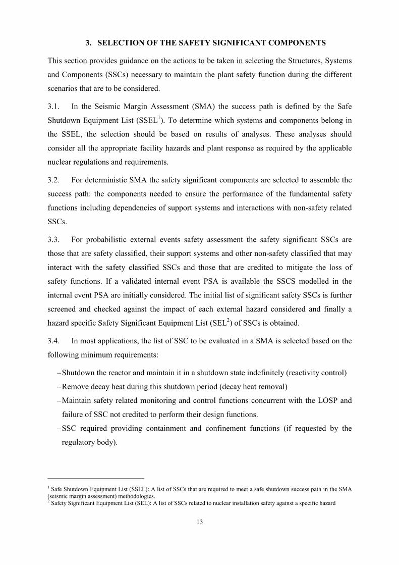
3. SELECTION OF THE SAFETY SIGNIFICANT COMPONENTS
This section provides guidance on the actions to be taken in selecting the Structures, Systems
and Components (SSCs) necessary to maintain the plant safety function during the different
scenarios that are to be considered.
3.1. In the Seismic Margin Assessment (SMA) the success path is defined by the Safe
Shutdown Equipment List (SSEL1). To determine which systems and components belong in
the SSEL, the selection should be based on results of analyses. These analyses should
consider all the appropriate facility hazards and plant response as required by the applicable
nuclear regulations and requirements.
3.2. For deterministic SMA the safety significant components are selected to assemble the
success path: the components needed to ensure the performance of the fundamental safety
functions including dependencies of support systems and interactions with non-safety related
SSCs.
3.3. For probabilistic external events safety assessment the safety significant SSCs are
those that are safety classified, their support systems and other non-safety classified that may
interact with the safety classified SSCs and those that are credited to mitigate the loss of
safety functions. If a validated internal event PSA is available the SSCS modelled in the
internal event PSA are initially considered. The initial list of significant safety SSCs is further
screened and checked against the impact of each external hazard considered and finally a
hazard specific Safety Significant Equipment List (SEL2) of SSCs is obtained.
3.4. In most applications, the list of SSC to be evaluated in a SMA is selected based on the
following minimum requirements:
– Shutdown the reactor and maintain it in a shutdown state indefinitely (reactivity control)
– Remove decay heat during this shutdown period (decay heat removal)
– Maintain safety related monitoring and control functions concurrent with the LOSP and
failure of SSC not credited to perform their design functions.
– SSC required providing containment and confinement functions (if requested by the
regulatory body).
1 Safe Shutdown Equipment List (SSEL): A list of SSCs that are required to meet a safe shutdown success path in the SMA
(seismic margin assessment) methodologies. 2 Safety Significant Equipment List (SEL): A list of SSCs related to nuclear installation safety against a specific hazard

14
3.5. System analyses and their results are typical provided in a SAR for the facility being
evaluated and the SEL should be based on information provided in the SAR.
3.6. SEL may include operator action to be credited for restoring the functions of certain
SSCs that could be temporary affected by the external hazards. In order to credit operator
actions, as necessary the following conditions should be met:
– Procedures and training are in place
– Procedures take into account the environment which will result from the SME/S-PSA
– Operator actions utilize seismically qualified components and I&Cs
– Egress routes are confirmed viable by review against external hazard capable engineer.
All alternate egress routes must be included in operator action procedures, unless a single
route is structurally qualified (including opening of doors and emergency lighting). In
addition, access routes for the operator to active alarms may be required.
3.7. Appendix 2 presents more guidelines for selection of SSEL.
SHORT AND LONG TERM SCOPE FOR SELECTION OF SAFETY SIGNIFICANT
COMPONENTS
3.8. SEL basically represents the scope of work in external events safety evaluation. The
amount of work depends on how large is this list (the number of SSCs that have to be
evaluated). For full scope evaluation SEL may include from 600 to more than 1000 of items.
3.9. Short term option is valid only for deterministic approach (SMA) by limiting the
number of items from SEL using conservative assumptions like:
– Offsite Power is not available (power supply is provided only by the diesel generators)
– Load Shading – (not all diesel required to supply power are available)
– Station Blackout – (emergency power is not available - all diesels failed to supply
auxiliary and emergency power),
– Loss of normal heat removal path.
– Loss of Ultimate Heat Sink, etc.
3.10. Reducing the number of items included in SEL, based on conservative assumptions
means reduction of the scope of safety evaluation to a manageable size in a relatively the
short time.

15
4. EXTERNAL EVENTS SAFETY ASSESSMENT METHODOLOGY
4.1 This section presents the different approaches that can be taken in assessing the safety
margins of the plant for a given initiating hazard. Only seismic and flood external hazards are
presented in this document. Safety assessment for other hazards basically follows the same
main elements as for seismic hazard (considered the most complex methodology) taking into
account the specific impact of each hazard to the plant fundamental safety functions.
4.2 The effects of external hazards on a nuclear power plant site may have a major impact
on the safety of the plant and may lead to initiating events (IEs) that have to be included in the
plant safety analysis. External hazards such as seismic and flood may cause CCF for safety
related systems, with the associated possibility of degradation or losing the safety functions.
4.3 Seismic safety assessment methodology is the most complex one and is presented in
detail. Flooding safety assessment follows the same main processes as seismic safety
assessment, though there is less industry experience available. Differences are in the flood
effects and SSCs fragility or failure capacity. Also the safety significant SSCs impacted by
flood hazards are different from those impacted by seismic hazards.
SELECTION OF METHODOLOGY
4.4 Two types of methodologies are generally available for safety assessment against
external hazards:
– Deterministic safety assessment aimed at evaluating the failure capacity (beyond design
basis) of the success path. The success path is defined by the availability of SSCs
required to perform the fundamental safety functions and to bring and maintain the NPP
in a safe shutdown state.
– PSA aimed to evaluate the contribution to all possible accident sequences and scenarios
induced by external IEs.
4.5 Both methodologies are discussed in detail in this report: the S-PSA, and the
deterministic SMA. Guidelines for implementing both methodologies are given in IAEA
Safety Guide NS-G-2.13 [8]. The S-PSA and SMA methodologies are mature after 30 years
of development and applications. ANS developed a standard for the application of
probabilistic risk assessment methodologies to external events for nuclear power plants
entitled “ANS: External-Events PRA Methodology.” This ANS Standard was published first

16
in 2003, updated in 2007, and became part of ASME/ANS Standard RA-S-2008, Part 4 in
2008 [9].
4.6 Appropriate methodology (deterministic or probabilistic) should be selected based on
objectives and scope established in line with the regulatory requirements and in consultation
and agreement with the Regulatory Body
S-PSA METHODOLOGY
4.7 PSA is an integrated process whose end goal is to provide an estimate of the overall
frequency of failure of a pre-determined plant level damage state, such as reactor CDF, or
frequency of large releases. The S-PSA includes consideration of the uncertainty and
randomness of the seismic hazard, uncertainty and randomness of component failure rates
conditional upon earthquake ground motion, and a logic tree required to calculate plant level
damage states from component and system failure rates from random failures and operator
errors.
4.8 The main elements of the S-PSA methodology are:
(a) Seismic Hazard Analysis: provides input for calculation of seismic IEs frequencies,
analysis of structural response and calculation of seismic demand
(b) Data collection and plant familiarization (plant specific as-built and as operated as
well as generic seismic capacity data for the safety significant SSCs).
(c) Structural Response Analysis including SSI or Equipment Structure Interaction when
appropriate and develop ISRS – seismic demand (this could be listed as part of
Seismic Fragility Evaluation).
(d) Seismic Fragility Evaluation: to estimate the conditional probability of failure of
important structures systems and components whose failure may lead to unacceptable
damage to the plant; screening and plant walkdowns are important activities in
conducting this task;
(e) Systems/Accident Sequence Analysis: starts with development of S-PSA database and
development of the logic models of the various combinations of structural and
equipment failures (including HRA and seismic induced flood, fire, internal explosion,
etc.), for seismic events that could initiate and propagate a seismic core damage
sequence;

17
(f) Risk Quantification: assembly of the results of the seismic hazard, fragility, and
systems analyses to estimate the frequencies of core damage and plant damage states,
including sensitivity analysis. Also includes development of S-PSA insights.
4.9 The end results of the S-PSA include:
(a) Seismic minimal cutsets and dominant accident sequences initiated by seismic event
(b) Plant State Fragility
(c) Seismic safety margin at component level and plant level
(d) Seismic vulnerabilities based on dominant contributors (system functions and
components) to seismic CDF/LERF based on importance factors risk reduction and
sensitivity analysis
(e) Relative contribution of seismic IEs
(f) Risk based plant improvements (seismic upgrades of SSCs)
4.10 The S-PSA flow chart is presented in Figure 4.1. Guidelines of S-PSA methodology
based on IAEA Safety Guide NS-G-2.13 [8] are presented in Appendix 3.
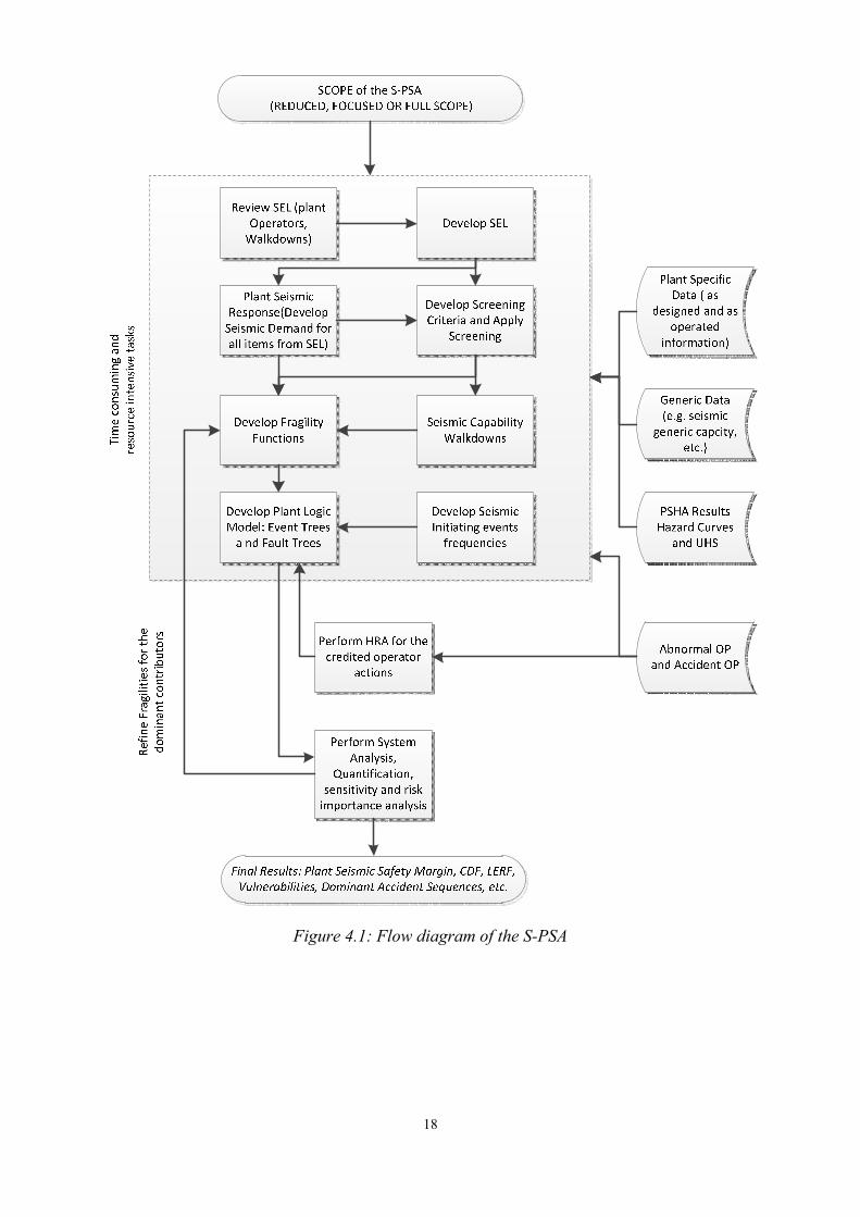
18
Figure 4.1: Flow diagram of the S-PSA

19
SMA METHODOLOGY
4.11 The concept of a High Confidence of Low Probability of Failure (HCLPF) capacity is
used in the SMA to quantify the seismic margin of individual Structures, Systems and
Components, SSCs and collectively of a nuclear power plant. This is a conservative, but
realistic capacity, and in simple terms it corresponds to the earthquake level at which, with
high confidence, it is extremely unlikely that failure of selected safety related SSC of a NPP
will occur.
4.12 A SMA typically consists of the following tasks:
– Selection of the Seismic Review Team, SRT
– Selection of the RLE,
– Definition of the SEL. In most applications of the SMA procedures SEL has been
limited to SSCs which make up a Reactor Safety Shutdown success path including
alternate redundant success path.
– Definition of the performance criteria
– Preparatory work to include assembly of existing seismic design documentation. Also
included in this effort would be a Relay Functional Review to identify low HCLPF
safety related relays, switchgears and level indicators.
– Plant Walkdowns
– SMA by Analysis (component and plant level)
– Identification of vulnerabilities and recommended resolution
– Documentation and report preparation
– Peer Review
4.13 The end results of the SMA include:
– Seismic safety margin at component level and plant level
– Seismic vulnerabilities
– plant improvements (seismic upgrades of SSCs)
4.14 The SMA flow chart is presented in Figure 4.2. Guidelines of S-PSA methodology
based on IAEA Safety Guide NS-G-2.13 [8] are presented in Appendix 3.

20
Figure 4.2: Flow diagram of SMA
SHORT TERM AND LONG TERM SEISMIC SAFETY ASSESSMENTS
4.15 The safety assessment may have to be undertaken on short term and long term basis.
(a) Short term safety assessment
In the short term the deterministic SMA can be used together with conservative
assumptions aimed to reduce the list of SSCs that require HCLPF evaluation.
Furthermore the HCLPF evaluation can be conducted using conservative assumptions
base on design review and expert judgement. All these assumptions and engineering
judgements should be well documented and the conservatism of the assumptions used
should be demonstrated. Theses simplifications should lead to a conservative estimate
of the plant seismic safety margin as compare to the full scope SMA results.
(b) Long term safety assessment

21
Long term safety assessment should be done adopting detailed analytical approach for
evaluation of hazard and assessment methodology discussed in Appendix 3 which is
based on the requirements and guidance of IAEA Safety Standards and validated
industry practice.
SUMMARY OF SMA AND S-PSA
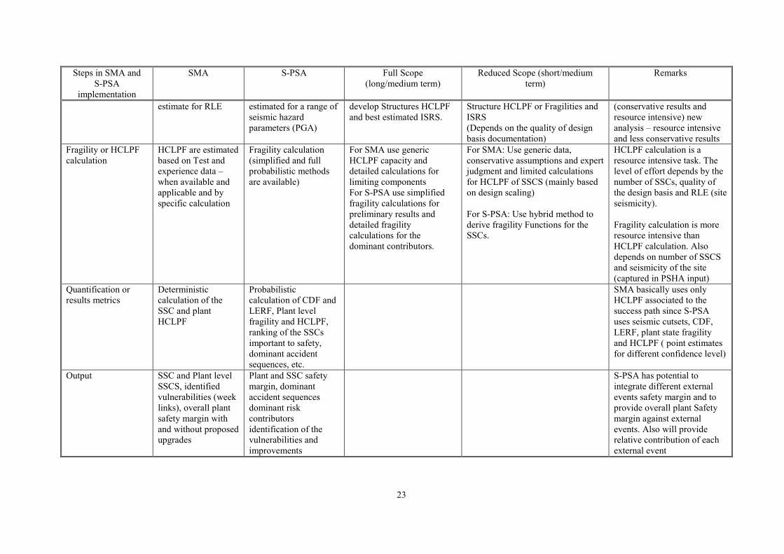
4.16 Table 4.1 presents the summary of SMA and S-PSA showing common and differences
between implementation steps. Also indicates full and reduced scope (associated to short and
long terms) indicating resource intensive tasks.

22
TABLE 4.1. SUMMARY OF SMA AND S-PSA METHODOLIES
Steps in SMA and
S-PSA
implementation
SMA S-PSA Full Scope
(long/medium term)
Reduced Scope (short/medium
term)
Remarks
Seismic Input:
RLE
RLE is specified as a
ground response
spectra anchored to a
specified PGA
evaluated from the
available site specific
hazard assessment
Probabilistic Seismic
Hazard Assessment
(Hazard curves for
different confidence
level and median shape
UHS
Site Specific RLE based on
full PSHA (for S-PSA) and
PSHA or DSHA for SMA.
Site Specific based on existing
design basis information
complemented by conservative
expert judgement and assumptions
(Less resource intensive)
For SMA the RLE is set to
the target margin (above the
design basis) and is used in
capacity and margin
evaluation.
For S-PSA the hazard curves
are used to calculate the
frequency of the Seismic IEs
and RLE is used for fragility
calculations.
Plant Model or
System Model
Success Path Event trees and Fault
Trees
Full Success path including
redundant(s) chains should
be develop for SMA as
outlined in the full
methodology.
For S-PSA: Plant logic
model should be develop
Validated Internal Event
PSA should be used as
initial basis:
- Develop/modify Event
Trees to include
Seismic IEs
- Modify Fault Trees to
include seismic basic
events and associated
logic.
For SMA: the success path can be
reduced using conservative
assumption:
a) credit only on minimum safety
systems for ultimate heat sink
and emergency power supply
(considering that other systems
are unavailable).
The effort is given by the number of
SSC from SEL. Using conservative
assumptions this number can be
reduced.
For S-PSA :
b) Point estimates only for the
CDF/LERF
c) Use Hybrid Method to generate
fragility parameters
d) PSA based SMA
Reduced scope S-PSA cannot be
implemented in short time
Development of the Success
Path (deterministic approach)
is less resource intensive
since development of the
plant logic model for S-PSA
is a resource intensive tasks
(PSHA, Fragility Evaluation,
etc.)
Seismic Response
Analysis
Deterministic or
Probabilistic best
Deterministic or
probabilistic best
For both SMA and S-PSA:
Perform New Analysis to
For both SMA and S-PSA:
Use Design Scaling to derive
Can be derived based on
design FRS scaling
23
Steps in SMA and
S-PSA
implementation
SMA S-PSA Full Scope
(long/medium term)
Reduced Scope (short/medium
term)
Remarks
estimate for RLE estimated for a range of
seismic hazard
parameters (PGA)
develop Structures HCLPF
and best estimated ISRS.
Structure HCLPF or Fragilities and
ISRS
(Depends on the quality of design
basis documentation)
(conservative results and
resource intensive) new
analysis – resource intensive
and less conservative results
Fragility or HCLPF
calculation
HCLPF are estimated
based on Test and
experience data –
when available and
applicable and by
specific calculation
Fragility calculation
(simplified and full
probabilistic methods
are available)
For SMA use generic
HCLPF capacity and
detailed calculations for
limiting components
For S-PSA use simplified
fragility calculations for
preliminary results and
detailed fragility
calculations for the
dominant contributors.
For SMA: Use generic data,
conservative assumptions and expert
judgment and limited calculations
for HCLPF of SSCS (mainly based
on design scaling)
For S-PSA: Use hybrid method to
derive fragility Functions for the
SSCs.
HCLPF calculation is a
resource intensive task. The
level of effort depends by the
number of SSCs, quality of
the design basis and RLE (site
seismicity).
Fragility calculation is more
resource intensive than
HCLPF calculation. Also
depends on number of SSCS
and seismicity of the site
(captured in PSHA input)
Quantification or
results metrics
Deterministic
calculation of the
SSC and plant
HCLPF
Probabilistic
calculation of CDF and
LERF, Plant level
fragility and HCLPF,
ranking of the SSCs
important to safety,
dominant accident
sequences, etc.
SMA basically uses only
HCLPF associated to the
success path since S-PSA
uses seismic cutsets, CDF,
LERF, plant state fragility
and HCLPF ( point estimates
for different confidence level)
Output SSC and Plant level
SSCS, identified
vulnerabilities (week
links), overall plant
safety margin with
and without proposed
upgrades
Plant and SSC safety
margin, dominant
accident sequences
dominant risk
contributors
identification of the
vulnerabilities and
improvements
S-PSA has potential to
integrate different external
events safety margin and to
provide overall plant Safety
margin against external
events. Also will provide
relative contribution of each
external event
24
FLOOD SAFETY MARGIN EVALUATION
4.17 The effects of flooding on a nuclear power plant site may have a major impact on the
safety of the plant. The presence of water in many areas of the plant may be a common cause
failure (CCF) for safety related systems, such as the emergency power supply systems or the
electric switchyard, with the associated possibility of losing the external connection to the
electrical power grid, the decay heat removal system and other vital systems.
4.18 Deterministic safety margins are developed from design basis analysis to ensure that
operation of a nuclear power plant can be carried out with adequate levels of safety in all
modes of operation and at all times. The basic concept is to determine limiting values, which,
if exceeded, could lead to an undesirable state. Same concept as for SMA can be used for
beyond design basis flood.
4.19 Probabilistic approach aims at achieving completeness in identifying possible faults,
deficiencies and plant vulnerabilities, and providing a balanced picture of the safety
significance of a broad spectrum of issues, including the uncertainties of the numerical results.
4.20 The collective experience with PSA external-flooding analysis is limited. The
technical requirements for external flooding PSA including local precipitation are similar,
with adaptations, to those for internal-flooding PSA and S-PSA. The major elements of the
PSA methodology are:
– flooding hazard analysis;
– flooding fragility analysis (involving analysis of flooding pathways and water levels);
and
– systems analysis including quantification.
4.21 There are several types of external-flooding phenomena that need to be considered,
depending on the site. These include both natural phenomena (high river or lake water, ocean
flooding such as from high tides or wind-driven storm surges, extreme precipitation,
tsunamis, seiches, flooding from landslides, etc.), and man-made events (principally failures
of dams, levees, and dikes). It is also important to consider rational probabilistic-based
combinations of the above phenomena.
4.22 Fragility analysis for both capacity and demand may be based on the standard
methodology used for seismic events, with appropriate modifications unique to the flooding
event being studied.

25
4.23 The procedure for determining the accident sequences is similar to that used in S-PSA
systems analysis. Other factors to be considered include non-flooding-related unavailability or
failures of equipment, operator errors, any warning time available to take mitigating steps, the
possibility of recovery actions by operators and replacement by substitutes to accomplish the
needed function; and the likelihood of common-caused failures. The clogging of intake
structures and other flow paths by debris related to the flooding must also be considered, and
a walkdown is important to assure that this issue has been evaluated properly.
4.24 The end results of the external flood PSA includes:
– Flood minimal cutsets and dominant accident sequences initiated by external flood
event
– Plant State Fragility
– Flood safety margin at component level and plant level
– External flood vulnerabilities based on dominant contributors (system functions and
components) to external flood CDF/LERF based on importance factors risk reduction
and sensitivity analysis
– Relative contribution of flood IEs
– Risk based plant improvements (external flood upgrades of SSCs)
– More details about external flood PSA methodology are presented in [9].
SHORT AND LONG TERM FLOOD SAFETY ASSESSMENT
4.25 Short term safety assessment
In the short term the deterministic safety margin can be developed from design basis analysis
and following the steps from SMA considering the flood specific aspects. The basic concept
is to determine limiting values of the success path, which, if exceeded, could lead to an
undesirable state. Same as for reduced scope SMA the number of SSCs considered in analysis
can be reduced based on conservative assumption and SSCs flood failure capacity can be
estimated on conservative basis.
All these assumptions and engineering judgement should be well documented and the
conservatism of the assumptions used should be demonstrated. These simplifications should
lead to a conservative estimate of the plant external flood safety margin.
4.26 Long term safety assessment

26
Long term safety assessment should be done adopting detailed analytical approach for
evaluation of the external flood hazard discussed in Appendices 1 and safety assessment
methodology based on the requirements and guidance validated industry practice [9].

27
5. FUNDAMENTAL SAFETY FUNCTIONS
5.1 The series of events that occurred at Fukushima NPP as a result of a combination of
extreme external hazards that breached several levels of the plant defence in depth, pointed to
the need to investigate the robustness of the defence in depth provisions in plant designs,
particularly at the levels 3 and 4 in the IAEA terminology (INSAG-10 [10] and NS-R-1
[11]), that are aimed at controlling accidents within the design basis and the prevention of
accident progression and mitigation of severe accident consequences respectively.
5.2 This combination of earthquakes and tsunamis at Fukushima and other Japanese NPPs
resulted in permanent or long term damage of safety support systems, namely power supplies,
and cooling water supplies (heat sink), which hampered the fulfilment of the plant safety
functions and the management of the resulting severe accidents in case of the Fukushima Dai-
ichi plant.
5.3 To this aim, and in the light of the events that occurred in Japan, the prolonged loss of
power and cooling water supplies required by the fundamental safety functions needs to be
investigated. These important systems have proved to be particularly vulnerable in some
designs because of the exposure to external hazards, including diesel generators and their
cooling systems.
SCOPE OF THE ASSESSMENT
5.4 The prime objective of the assessment is to evaluate the robustness of the existing
plant protection in terms of design features and procedures against the impact of extreme
events focusing on fulfilment of the fundamental safety functions of criticality control,
residual heat removal, and confining the radioactive material.
5.5 The approach should be to complete this in a comprehensive and systematic way,
focusing on the assessment of the plant from the perspective of defence-in-depth as defined in
IAEA Safety Standards. The specific plant vulnerabilities and actions needed to improve plant
and mitigation actions should be identified and improvements for safety recommended.
5.6 The assessment should have in its scope the following areas:
– Consideration of accident scenarios originated by extreme events that cause extensive
damage to safety systems and challenge the fulfilment of the fundamental safety
functions;

28
– accident progression leading to damage of the reactor core or fuel stored at the site and
associated severe accident management procedures to provide information for later parts
of the methodology;
– interactions between plant units at multi-unit sites and the accident scenarios involving
simultaneous failures of containments;
– consideration of other evaluations whose results may have a bearing on this assessment
review and so enable attention to be drawn to potential safety improvements as
appropriate.
5.7 The approach should focus on examination of accident scenarios leading to fuel
damage (thus addressing the functions of criticality control and residual heat removal), and
then proceeding to further examination of the accident scenarios that might lead to radioactive
releases (thus addressing the function of containing/confining the radioactive material). In this
process, possible measures to mitigate the consequences can be examined.
5.8 The approach should aim to identify the minimal combinations of components and
human actions that are needed to protect the plant against the impact of extreme events.
ASSESSMENT OF THE FUNDAMENTAL SAFETY FUNCTIONS
5.9 The assessment of the safety functions will consist of a verification of the lines of
defence in depth following a postulated extreme event in the plant that will affect two safety
system support functions: power supply and ultimate heat sink.
Compliance of the Power Supply Systems and Ultimate Heat Sink with the relevant
IAEA safety standards
5.10 The first step of the assessment will consist in an assessment of compliance of the
power supply systems and ultimate heat sink with the relevant IAEA safety standards, such
as:
– NS-R-1 (to be replaced by SSR-2.1, in publication): Requirements for Safety of Nuclear
Power Plants: Design [11]
– NS-G-1.8: Design of Emergency Power Systems for Nuclear Power Plants [12]
– NS-G-1.9: Design of the Reactor Coolant System and Associated Systems in NPPs [13]
– GSR Part 4:Safety Assessment of Facilities and Activities [14]
5.11 It is expected that the plant design would comply largely with these standards, as
many Member States make use of the standards in different ways in their licensing process.
However, the margin of compliance is the aspect of interest. For assessing this margin a

29
sequential and progressive loss of the available supply possibility should be postulated an
analysed deterministically, irrespectively of its probability.
5.12 The assessment should consider all plant operational modes for making conservative
assumptions regarding the plant conditions to be assumed in the assessment, plant power, fuel
condition, system alignments and availability according to the plant technical specifications,
etc. In this regard, it is important to note, that when a plant has several units, the postulated
conditions would affect all units and facilities at once, and that degraded conditions could
exist for the implementation of alternative power supply or cooling methods, particularly
those that entail measures that have not been foreseen in the plant design, EOPs or SAMGs.
5.13 The assessment should reflect, the provisions already included in the plant design
basis. This should be part of the review against the applicable IAEA safety standards. In
addition, the assessment should reflect the strengths of the design in terms of redundancy,
diversity, physical separation and other features relevant to cope with stepwise losses of
supply sources and functionality. In this regard it is relevant to determine the limiting
situations that could arise for accomplishing the safety functions when supplies fail (cliff edge
effects) and the measures that are already in place or could be implemented to avoid reaching
these situations and improve the defence in depth provisions.
Consequences of support system failures and their impact on maintaining the
fundamental safety functions
5.14 The assessment of consequences of support system failures needs to assess their
impact on maintaining the fundamental safety functions. The assessment has to account for
the failures that could be originated by the extreme events postulated. This assessment can be
facilitated by a number of methods and tools, such as:
– List of electrical bus bar loads
– Plant configuration or dependency matrixes
– Failure mode and effect analysis (FMEA)
– PSA analysis models and risk monitors
– Plant simulators, etc.
5.15 The use of these tools should be properly documented to allow independent review.
Priority should be given to the extent possible to licenced tools or documentation and
documentation that are part of a management system programme (quality assurance). These
tools relate to provisions existing in the design. The analysis should also identify additional
measures, such as the use of portable equipment, alternative water supplies, etc. with
30
consideration of possibilities for sharing equipment and supplies between different units at the
same site and the safety implications for both.
5.16 A plant walkdown for assessing in situ the vulnerability of equipment to hazards and
verifying the viability of compensatory measures should be carried out when necessary.
5.17 The analysis should be accompanied also by the necessary information about the plant
and its systems that are necessary for a good understanding of the assessment.
5.18 The assessment will encompass the following:
Loss of AC Power supplies
5.19 In the light of the events occurred at Fukushima or any other extreme event that could
be postulated at the site, the assessment should consider that offsite power supply could not be
restored for a long period of time. The existing power supply sources should be considered in
the assessment:
– Off-site power supply sources
– Emergency Power Supply systems (EPS) providing power in any operational state or in
the case of a design basis accident to safety buses, as defined in NS-G-1.8 [12], e.g.
emergency diesel generators.
– Other available back up sources available.
The assessment needs to consider the functionality and stepwise loss of these sources after an
extreme hazard.
(1) LOSP sources
The available sources need to be identified, and despite of redundancy and diversity, be
considered unavailable for a long period of time, as a result of the consequences of
extreme events on site and off site. Plant capabilities for working in an “islanded
mode”, i.e. automatic disconnection from of the plant generator from the grid and rapid
reduction in reactor output to supply power for the NPP unit’s own consumption,, can
be considered in the short term, where this is an established feature of the NPP’s design
where it can be demonstrated the extreme event would not affect this capability
The assessment should consider the impact on plant operation and the preservation of
the fundamental safety functions in the short and long term.

31
On the event of a LOSP, the assessment should describe the measures in place for
coping with this situation, i.e. internal power generation methods and how long it can be
maintained without aggravation, e.g. assurance of fuel supply to diesel generators.
(2) Loss of external and internal power supply - Station Black Out (SBO)
SBO, as defined in NS-G-1.8 [12] is the complete loss of AC power supplies from off-
site, the plant power generator and the EPSs. It does not include the failure of
uninterruptible AC power supplies, or the failure of alternative AC power sources. The
assessment should consider first the impact of the failure of emergency power supply
systems which are designed to supply automatically the buses powering the safety
related equipment.
(3) Failure of additional back up equipment
In a further step, the assessment should consider the failure of additional back up
equipment that can exist and be ready to be put into service in case of a station black out
scenario to power some important equipment, such as additional back up diesels
available at some plants, e.g. SBO diesel, portable generators, etc. which can provide
power to DC or instrumentation buses, or a limited amount of vital equipment.
The assessment should address compliance with additional recommendations provided
in NS-G-1.8 [12] regarding measures in SBO, such sharing power supplies with other
units and measures to extend the duration of DC power supply.
In any of these scenarios, the assessment should review the plant design and assess the
impact on the fundamental safety functions. For this purpose the following aspects need
to be investigated:
– Availability of equipment in the short and long term during station blackout to fulfil
the functions, including:
– Cooling equipment not requiring AC power, e.g. turbine driven pumps.
Consideration needs to be given to steam, instrument air, DC power that they
might need.
– Duration of batteries and measures to prolong it, e.g. disconnecting loads, using
portable chargers, etc.
– Degradation of barriers, e.g. development of main coolant pump seal LOCA.
– Assessment of the consequences of loss of batteries and subsequent failure of DC
power supply and instrumentation, including the identification of instrumentation
32
that can provide local measures without power supply, e.g. some types of pressure
and level meters
– Assessment of the time available until the onset of core/fuel damage if remediation
measures are not taken. Assessment of measures foreseen to prevent it, including:
– Equipment already available on site, e.g. from other units and off site, that could
be brought or connected to the plant.
– Assessment of the time required for such measures and availability of competent
staff to perform them.
– Assessment of the automatic actions, protective measures, interlocks, or other
features in the electrical systems, reactor protection system, load sequencer or
other systems, that could prevent the connection of foreign equipment or cause
unexpected events.
– Identification of the limiting situations that could arise and additional measures
(design modifications, procedures, etc.) that could be taken to enhance the robustness
of the defence in depth.
Loss of Ultimate Heat Sink
5.20 As per definition the in Safety Guide NS-G-1.9 [13], the ultimate heat sink is normally
a body of water, the groundwater or the atmosphere, to which medium some part of or all
residual heat is transferred in normal operation, anticipated operational occurrences or
accident conditions. The heat sink considered here is not the one used to evacuate heat from
the turbine condenser during normal operation, unless it is also the same used for residual heat
removal, e.g. sea or river.
5.21 Depending on the site characteristics, a design may include more than one ultimate
heat sink. Also at sites with several units, it could be possible that several units share an
ultimate heat sink, and even heat transport systems to them, in which case potential
interaction between both units need to be considered.
5.22 The assessment here refers to the ultimate heat sink itself and not to the intermediary
heat transport systems to remove heat from the core. The heat sink includes not only the body
of water or the atmosphere but the structures (pools, water intake, etc.) associated with them.
Therefore, a failure of the heat sink includes the excessive accumulation of mud, dirt, etc. in
the water, the plugging or failure of intake structures, etc., particularly during extreme event
conditions. It can no longer be claimed that the ultimate heat sink cannot fail on the basis that
the atmosphere or the sea will always be available.
33
5.23 As with the loss of power supplies, if several heat sinks are available in the design, the
assessment should consider the stepwise failure of the heat sinks, and that they will remain
unavailable for a long period of time. Realistic considerations can be made for supplying the
plant with back-up water inventories, e.g. fire trucks, after a certain period of time.
5.24 The assessment needs to consider the alternative water sources existing in the design
that could be available for ensuring the fulfilment of the safety functions, the provisions to
protect them and to align them to the heat removal systems.
5.25 The assessment needs to determine the time available from the loss of the ultimate
heat sink(s) until the onset of core/fuel damage without the use of external resources. It has to
provide information on the provisions in the design and necessary actions and time needed to
use alternative resources to restore heat removal using alternative heat sinks. In doing this
assessment, account needs to be taken of the potential severe conditions on the site after an
extreme event; the availability of equipment on site or brought to the site to connect and pump
water into the systems; the necessary time to bring alternative heat sinks into operation; and
the availability of qualified personnel to do it, considering also that all units on the site have
been affected by the extreme event.
5.26 As a result of the assessment, potential weaknesses in the defence in depth should be
identified, as well as additional measures that should be incorporated to eliminate them or
increase the robustness of the plant.
Combined loss of ultimate heat sink and SBO
5.27 This extreme and most limiting scenario should be finally considered taking into
account the similarities and overlapping effects and root causes of SBO and loss of ultimate
heat sink for preserving the fundamental safety functions.
5.28 As in the previous cases, the assessment needs to determine:
– For how long severe damage to the core/fuel can be prevented upon failure of the
ultimate heat sink(s) and SBO conditions, without eternal support to restore these
supplies.
– Provisions in the design and necessary internal actions to recover from this scenario.
– Necessary external actions to prevent core/fuel damage accounting for the situation
prevailing at the site after an extreme event; the availability of equipment on site or
brought to the site; the necessary time to make equipment operable; and the availability

34
of qualified personnel to do it, considering also that all units on the site have been
affected by the extreme event.
5.29 The assessment of all the postulated scenarios should eventually identify the possible
limiting situations that could arise, and the additional measures that should be incorporated in
the design to increase its robustness.
35
6. SEVERE ACCIDENT MANAGEMENT
6.1 A main lesson from the Fukushima-Dai-ichi accident is that both the extensive
destruction of the site and SSCs, as well as the actions and capabilities of the operating
organization and external support to manage the accidental situation were very relevant
factors for the outcome of the accident. This section deals with the second of these factors. It
addresses in particular the need for assessment of severe accident management in scenarios
originated by extreme events at nuclear power plants.
6.2 The management of severe accidents is based mainly upon design features such as
systems and design provisions for severe accidents; technical and human resources, including
portable equipment; and adequate organization, procedures and training.
THE ASSESSMENT METHODOLOGY
6.3 The objective of this methodology is to assess the adequacy and robustness of the
accident management programme under the conditions of extreme events defined in this
document. This assessment needs to be performed even if the accident scenarios associated
with these events are of a very low probability. Failing to undertake the appropriate accident
management actions can lead to very high consequences and there is a significant potential for
cliff edge effects. Therefore, accident management has to be consistent and integrated with
the measures established for controlling accident progression in the previous level of defence.
A working assumption in the methodology is therefore that in the postulated scenarios for
extreme events, see previous sections, core or fuel damage will eventually occur.
6.4 As basis for the assessment, it is understood that the operating organization has
already analysed and established an accident management programme. This programme is the
starting point of the analysis for the consideration of the specific aspects associated with the
occurrence of extreme events. When a plant has not developed a comprehensive severe
accident programme, such a programme should be developed or completed. The IAEA has
developed safety standards [19], [25] and guidelines for the development of a severe accident
management programme [21] Implementation of Accident Management Programmes in
Nuclear Power Plants, Safety Reports Series, No. SRS-32, IAEA, Vienna (2004). Overview
of Training Methodology for Accident Management at Nuclear Power Plants, Technical
Document No. TECDOC-1440, IAEA, Vienna (2005)) and makes available to MSs an
international peer review service (RAMP) to assess the adequacy and completeness of severe
36
accident management programmes at nuclear power plants (ref. Guidelines for the review of
accident management programmes in nuclear power plants, IAEA Services Series No. 9,
Vienna (2003).)
6.5 These documents as well as a newly developed document for the review of severe
accident management guidelines including scenarios of extreme events (Ref.
SAS/NSNI/MELS/WD-1/Rev1/2011: Review of EOP and SAMG including Extreme Events
(EEs) constitute the basis for the assessment methodology presented in this section and
provide additional technical details and guidance for carrying out the assessment.
6.6 Typically, accident management measures in a nuclear power plant are aimed at the
first instance at preventing ore delaying to the extent possible damage to the reactor core
when the Emergency Operating Procedures (EOPs) and safety systems are not useful anymore
to prevent core damage. In such case, the transition should be made to specific guidelines
developed to mitigate the effects of core damage: the Severe Accident Management
Guidelines (SAMGs). While SAMGs still indicate actions to delay or limit the extension of
core damage, the main focus of the SAMGs is not any longer to save the core, but to protect
fission product boundaries, so that releases can be prevented or mitigated, should they occur.
General actions under SAMGs are aimed at:
– preventing RCS failure,
– preventing containment damage as a result of several phenomena, such as over
pressurization, hydrogen combustion, or corium-concrete interaction (CCI).
Description of the accident management programme
6.7 The first step of the assessment is to provide a comprehensive description of the severe
accident management programme existing at the plant, highlighting its main technical,
organizational, and operational aspects aimed at limiting the damage to the core and prevent
the release of radioactivity, as indicated above.
6.8 The description should address the organization and means for managing severe
accidents and nuclear emergencies, which indication of the role of the different organizations,
human resources, the emergency plans, and centres from which the emergency is managed. It
should describe also the different type of equipment and facilities available for accidental
situations and emergencies, such as protective equipment, monitoring and management of
radioactive doses, communication equipment and information systems, surveillance of
meteorological conditions, etc. The description should address emergency drills, and training

37
and surveillance practices to maintain the effectiveness and operability of emergency response
organization.
6.9 From the point of view of the technical and operational aspects of severe accidents, a
description should be provided of the basis for the development of the accident management
programme, with indication of the accident analysis sequences and issues that support the
development of the programme and its main aspects, such as: identification of plant
capabilities, development of preventive accident management strategies, development of
severe accident management strategies, procedures and guidelines, evaluation of capabilities
and limitations of existing equipment and instrumentation and control (I&C), etc.
6.10 The description needs to address specifically the current accident management
measures in place for protecting the reactor core and spent fuel pool, when the relevant safety
functions (control of reactivity, loss of cooling) are lost or the plant cannot be controlled
following the EOPs.
6.11 The description should indicate the conditions for transition between prevention and
mitigation procedures/guidelines and select conservative accident sequence conditions, e.g.
loss of cooling with the reactor coolant system pressurized, for presenting the measures
foreseen in SAMGs to prevent or delay core/fuel damage, and restore cooling after damage
has occurred.
6.12 The description should indicate the accident management measures to protect the
reactor vessel and the reactor coolant system after the onset of fuel damage. The description
should also address the accident management measures and plant design characteristics for
confinement and prevention of radioactive releases to the environment. In this regard, the
description needs to address the measures for:
– Preventing the deflagration or detonation of combustible gases
– In vessel retention of molten core
– Ensuring and maintaining containment isolation
– Protecting the containment from over pressurization through cooling, venting or other
mechanisms, providing the relevant characteristics of the venting system for its
actuation, e.g. qualification, capacity for filtration of isotopes and means to limit the
impact on the environment.
– Protecting the containment liner and basemat penetration from interaction with molten
core.
38
– Controlling and preventing mechanisms that could result in containment bypass, such as
a creep break when filling the steam generators (for PWRs) with cold water to provide
cooling.
– Controlling and preventing recriticality
6.13 In a similar manner the relevant aspects for preventing the release of radioactivity
from spent fuel pools should be described, indicating the measures before and after losing the
biological shielding of water, before and after the initiation of fuel uncover, and before and
after hydrogen generation by fuel cladding oxidation. As the fuel pools may not be inside of
the containment, the description should address also the relevant aspects of radioactivity
confinement and dispersion of hydrogen to other areas.
6.14 The description has to also give due consideration to the support systems (cooling
water, electrical systems, instrument air, etc.) and instrumentation available to accomplish the
measures described for both the reactor and fuel pools and the necessary qualification for
working during severe accidents conditions, and to the capabilities to operate severe accident
management equipment from the main and auxiliary control room and local areas protected
against radiation.
6.15 As a result of this first stage of the assessment, plant weaknesses for the management
of severe accidents of technical, organizational or operational nature, could be identified
before the consideration of extreme event issues
Consideration of extreme events
6.16 The second step of the assessment is the identification and analysis of the limiting
situations that can be originated at the plant site and its surroundings in all extreme event
scenarios postulated, as described in previous sections, in order to evaluate the robustness of
and appropriateness of the accident management programme in place.
6.17 As an indication, the analysis should take into account (but not necessarily be limited
to) the following issues:
– Impact on general conditions at the plant site, in terms of accessibility to the site and
different areas of the plant and buildings and availability of relevant infrastructures, e.g.
communications, lighting, etc. as well as the impact, in a later stage, of radioactive
doses that could hamper internal work and receiving external support.
– Potential impact on habitability and conditions in relevant areas, such as main and
remote shutdown control room and technical support center.

39
– Damages or conditions imposed by an extreme event to SSCs that would limit the
capabilities of equipment to perform under accident conditions as required for the
success of accident management actions.
– For each particular scenario considered in the analysis originated by an extreme event,
the following should be identified:
o Effect on the necessary instrumentation to control the plant and response to the
conditions created by the scenario. Under extreme event and severe accident
conditions, it cannot be simply assumed that all instrumentation upon which
operator actions are taken is operable and correct. It is therefore important to
assess the impact of extreme events on instrumentation
o Limiting situations that could be given, e.g. depletion of batteries or water
reservoirs.
o Time available and surrounding circumstances for adequate diagnosis of the
situation and timely accomplishing of recovery actions, if possible, or until failure
of safety functions, degradation of the core or barriers.
o Possibilities for using portable equipment, and relevant aspects to put them into
service, e.g. transport, availability of suitable connections and fittings, tools,
human resources, competence and training, etc.
o Available guidelines EOPs and SAMGs and their adequacy for the scenario.
o Specific conditions created in the scenario in addition to overall plant impact that
may hamper or affect the performance of actions, such as: availability and
adequacy of instrumentation and control to undertake actions locally and remotely,
accessibility to specific local areas where equipment condition should be verified,
actions need to be taken, considering lighting, radiation, heat, smoke, steam, leaks
of flooded areas, accumulation of hydrogen, etc. and potential propagation of
these hazards when the areas are visited.
o Consideration of other factors, such as stress, fear, etc. that the extreme situation
can cause on performance of manual actions.
o Competition for resources for managing the accident situation (operation, local
actions, needs for replenishing water reservoirs, diesel fuel, etc.) and actions for
arresting the progression of hazard effects, e.g. floods or fires or other important
tasks.
o For multiunit sites, the positive and adverse effects of sharing equipment and
human resources should be also considered.
40
Reassessment of severe accident management
6.18 The third step of the assessment is the re-evaluation of the accident management
programme, to account for the potential weaknesses identified in the first step and
consideration of the accident scenarios and plant conditions identified for extreme events.
6.19 With all the information gathered a systematic assessment should be conducted to
assess the adequacy of the programme and provide when applicable recommendations for
improvements in the organizations involved in accident management and emergencies, all
relevant kind of infrastructures, plant design, EOPs and SAMGs, and training. The scope of
this re-evaluation and the level of detail and effort is very much dependent on the starting
situation and the extreme hazards and effects that will be considered at a particular plant.
6.20 A comprehensive, detailed and systematic process for the review and improvement of
EOPs and SAMGs for addressing extreme events is given in (Ref. SAS/NSNI/MELS/WD-
1/Rev1/2011: Review of EOP and SAMG including Extreme Events (EEs)). The document
covers in an integrated manner the elements for assessment, aspects and questions to address
in each part. An outline of the essential aspects in this process is given in the following.
6.21 The assessment method recommends an integrated assessment covering three items:
– The appropriateness of the development of EOPs/SAMG for the spectrum of DBA,
BDBA and severe accidents, arising from internal and external events
– The capability of EOPs/SAMG for mitigating accident sequences which include
extreme
– The capability of EOPs/SAMG capable for mitigating extensive damage on the site.
6.22 EOPs and SAMGs are developed on the basis of accident sequences. They include
internal and external events, plus a number of failures in supporting systems. However, these
accident sequences usually do not include extreme events. By enlarging the spectrum of
accident sequences with sequences resulting from extreme events, new challenges to the
critical safety functions (EOPs) and fission product boundaries (SAMGs) can be found, for
which the available EOPs/SAMG have not been developed. The damage to SSCs needed to
execute the EOPs/SAMG is analysed and fed back into the accident sequences. The work for
accident analysis in preparation for the definition of the accident management programme
consists of:
– The selection of accident sequences
– Information needed for analysis

41
– Selection of analytical tools
– Analysis of sequences without (effective) operator action
– Identification and analysis of prevention measures
– Identification and analysis of mitigation measures
– Quality Assurance and results
6.23 The development of the Accident Management Programme accounting for the impact
of extreme events on the basis of the accident analysis consists of the following elements:
– Selection and definition of the accident management programme
– Assessment of plant vulnerabilities
– Identification of plant capabilities
– Development of preventive accident management strategies
– Development of severe accident management strategies: technical issues and human
considerations.
– Development of procedures and guidelines
– Evaluation of capabilities and limitations of existing equipment and instrumentation and
control (I&C).
– Responsibilities and plant emergency arrangements
– Verification and validation of procedures and guidelines
– Education and Training needs and performance
6.24 For the development of these elements, the characteristics of challenges to
EOPs/SAMG during extreme events are addressed, including a list of items where SAMGs
may be improved and candidate areas for enhancement of the technical basis.
The IAEA provides an international safety review service of accident management
programme for nuclear power plants (RAMP), which is currently being reviewed to address
specific issues of extreme events. On the operational part of the implementation of accident
management, the OSART service has developed a module covering such operational aspects
including training and performance.

42
REFERENCES
[1] INTERNATIONAL ATOMIC ENERGY AGENCY, Site Evaluation for Nuclear
Installations, IAEA Safety Standards Series No. NS-R-3, IAEA, Vienna (2003).
[2] INTERNATIONAL ATOMIC ENERGY AGENCY, External Human Induced Events
in Site Evaluation for Nuclear Power Plants, Safety Standards Series No. NS-G-3.1,
IAEA, Vienna (2002).
[3] INTERNATIONAL ATOMIC ENERGY AGENCY, Seismic Hazards in Site
Evaluation for Nuclear Installations Plants, Specific Safety Guide No. SSG-9, IAEA,
Vienna (2010).
[4] INTERNATIONAL ATOMIC ENERGY AGENCY, Meteorological Events in Site
Evaluation for Nuclear Power Plants, Safety Standards Series No. NS-G-3.4, IAEA,
Vienna (2003) (To be replaced by DS417, in publication).
[5] INTERNATIONAL ATOMIC ENERGY AGENCY, Flood Hazard for Nuclear Power
Plants on Coastal and River Sites, Safety Standards Series No. NS-G-3.5, IAEA, Vienna
(2003) (To be replaced by DS417, in publication).
[6] INTERNATIONAL ATOMIC ENERGY AGENCY, Geotechnical Aspects of Site
Evaluation and Foundations for Nuclear Power Plants, Safety Standards Series No. NS-
G-3.6, IAEA, Vienna (2004).
[7] Draft IAEA Safety Standards, DS405, Volcanic Hazards in Site Evaluation for Nuclear
Installations, IAEA, Vienna (in publication).
[8] INTERNATIONAL ATOMIC ENERGY AGENCY, Evaluation of Seismic Safety for
Existing Nuclear Installations, IAEA Safety Standards Series No. NS-G-2.13, IAEA,
Vienna (2009).
[9] ASME/ANS Standard RA-S-2008, Part 4, ANS: External-Events PRA Methodology,
(2008).
[10] INTERNATIONAL ATOMIC ENERGY AGENCY, Defence in Depth in Nuclear
Safety, INSAG-10, IAEA, Vienna (1996).
[11] INTERNATIONAL ATOMIC ENERGY AGENCY, Safety of Nuclear Power Plants:
Design, IAEA Safety Standard Series No. NS-R-1, IAEA, Vienna, 2000 (to be replaced
by SSR-2.1 in publication).
[12] INTERNATIONAL ATOMIC ENERGY AGENCY, Design of Emergency Power
Systems for Nuclear Power Plants, IAEA Safety Standards Series No. NS-G-1.8, IAEA,
Vienna (2004).

43
[13] INTERNATIONAL ATOMIC ENERGY AGENCY, Design of the Reactor Coolant
System and Associated Systems in NPPs, IAEA Safety Standards Series No. NS-G-1.9,
IAEA, Vienna (2004).
[14] INTERNATIONAL ATOMIC ENERGY AGENCY, Safety Assessment for Facilities
and Activities, IAEA General Safety Requirements Part 4 No. GSR Part 4, IAEA,
Vienna (2009)
[15] INTERNATIONAL ATOMIC ENERGY AGENCY, OSART Guidelines, 2005 Edition,
Reference Document for IAEA Operational Safety Review Teams, IAEA, Vienna
(2005).
[16] INTERNATIONAL ATOMIC ENERGY AGENCY, Guidelines for the review of
accident management programmes in nuclear power plants Reference Document for
IAEA RAMP Safety Review Teams, IAEA, Vienna (2003).
[17] INTERNATIONAL ATOMIC ENERGY AGENCY, Safety of Nuclear Power Plants:
Design, Safety Standards Series No. SSR-2/1, IAEA, Vienna (Approved by BoG2011).
[18] INTERNATIONAL ATOMIC ENERGY AGENCY, Safety of Nuclear Power Plants:
Commissioning and Operation, IAEA Safety Standards Series No. SSR-2/2, IAEA,
Vienna, (2011).
[19] INTERNATIONAL ATOMIC ENERGY AGENCY, Severe Accident Management
Plan for Nuclear Power Plants, IAEA Safety Standards Series No. NS-G-2.15, IAEA,
Vienna, (2009).
[20] INTERNATIONAL ATOMIC ENERGY AGENCY, Implementation of Accident
Management Programmes in Nuclear Power Plants, Safety Reports Series, No. SRS-32,
IAEA, Vienna (2004).
[21] INTERNATIONAL ATOMIC ENERGY AGENCY, Approaches and Tools for Severe
Accident Analysis for Nuclear Power Plants, Safety Reports Series, No. SRS-56, IAEA,
Vienna (2008).
[22] INTERNATIONAL ATOMIC ENERGY AGENCY, Overview of Training
Methodology for Accident Management at Nuclear Power Plants, Technical Document
No. TECDOC-1440, IAEA, Vienna (2005).
[23] INTERNATIONAL ATOMIC ENERGY AGENCY, Safety Assessment and
Verification for Nuclear Power Plants, Safety Standards Series No. NS-G-1.2, IAEA,
Vienna (2001).
44
[24] INTERNATIONAL NUCLEAR SAFETY ADVISORY GROUP, Basic Safety
Principles for Nuclear Power Plants, 75-INSAG- 3 Rev.1, INSAG-12, IAEA, Vienna
(1999).
[25] INTERNATIONAL ATOMIC ENERGY AGENCY, Deterministic Safety Analysis for
Nuclear Power Plants: Operation, IAEA Safety Standards Series No. SSG-2., IAEA,
Vienna, (2009).
[26] INTERNATIONAL ATOMIC ENERGY AGENCY, Accident Analysis for Nuclear
Power Plants, Safety Reports Series No. 23, IAEA, Vienna (2002).
[27] INTERNATIONAL ATOMIC ENERGY AGENCY, Operational Limits and Conditions
and Operating Procedures for Nuclear Power Plants, Safety Standards Series No. NS-G-
2.2, IAEA, Vienna (2000).
[28] INTERNATIONAL ATOMIC ENERGY AGENCY, Preparedness and Response for a
Nuclear or Radiological Emergency, Safety Standards Series No. GS-R-2, IAEA,
Vienna (2002).
[30] INTERNATIONAL ATOMIC ENERGY AGENCY, Terminology Used in Nuclear
Safety and Radiation Protection, IAEA Safety Glossary, IAEA, Vienna, (2007).

45
APPENDIX I
HAZARD ASSESSMENT PROCEDURE
GENERAL REQUIREMENTS
I-1. The parameters to characterise the hazards should be so chosen that they can be used
easily in the safety evaluation of the NPP. During hazard assessment, consideration should be
given to the effects of the combination of the hazard with the ambient conditions such as
hydrological, hydrogeological, meteorological conditions.
I-2. Appropriate methodology shall be adopted for the hazards assessment. Methodologies
based either on deterministic approach or on probabilistic approach are acceptable. The
methodology adopted shall be justified in terms of being up to date and compatible with the
characteristics of the region. Irrespective of methodology, both epistemic and aleatory
uncertainties shall be taken into consideration to evaluate the parameters characterizing the
hazards.
I-3. Adequate database shall be developed for hazard assessment. Site specific data shall
be used as far as practicable in hazard evaluation. The site shall be adequately investigated
with regards to the site characteristics that have significant impact on the safety. Pre-historical,
historical and instrumentally recorded information and records, as applicable, of the
occurrences and severity of the hazards shall be collected for the region and shall be carefully
analysed for reliability, accuracy and completeness. The size of the region shall be large
enough to include all the features and areas that could be of significance in evaluating the
characteristic parameter of the hazards.
I-4. Detail specifications of general requirements of external hazard assessment are given
in IAEA Safety Standard NS-R-3 [1].
ASSESSMENT OF SEISMIC HAZARDS
I-5. Hazards due to earthquake induced ground motion shall be assessed for the site with
account taken of the seismotectonic characteristics of the region and specific site conditions.
A thorough uncertainty analysis shall be performed as part of the evaluation of seismic
hazards. Specific requirements for evaluation of vibratory ground motion parameters are
given in IAEA Safety Standard NS-R-3 [1].

46
Probabilistic Method
I-6. Basic elements of a probabilistic method to derive ground motion parameters
(response spectrum), also known as PSHA, are:
(1) Evaluation of the seismotectonic model for the site region in terms of the defined
seismic sources, including uncertainty in their boundaries and dimensions;
(2) For each seismic source, evaluation of the maximum potential magnitude, the rate of
earthquake occurrence and the type of magnitude–frequency relationship, together with
the uncertainty associated with each evaluation;
(3) Selection of the attenuation relationships for the site region, and assessment of the
uncertainty in both the mean and the variability of the ground motion;
(4) Perform probabilistic hazard calculation and derive hazard curves for different
confidence level;
(5) Perform site response analysis to derive the site specific response spectra at free field or
any specified condition from the hazard.
I-7. The results of the PSHA are typically displayed as the mean or median annual
frequency of exceedance of measures of horizontal and vertical ground motion that represent
the range of periods of importance with regard to structures, systems and components. An
acceptable method for propagating the epistemic uncertainties through the PSHA is the
development of a logic tree, which can be evaluated by one of the following methods: (1)
complete enumeration of the logic tree branches; or (2) Monte Carlo simulation.
Deterministic Method
I-8. The assessment of seismic hazard to derive response spectrum by deterministic
methods should include:
(1) Evaluation of the seismotectonic model for the site region in terms of the defined
seismic sources identified on the basis of tectonic characteristics, the rate of earthquake
occurrence and the type of magnitude–frequency relationship;
(2) For each seismic source, evaluation of the maximum potential magnitude;
(3) Selection of the attenuation relationships for the site region and assessment of the mean
and variability of the ground motion as a function of earthquake magnitude and seismic
source to site distance;
(4) Perform deterministic hazard calculation as follows:

47
i) For each seismic source, the maximum potential magnitude should be assumed to
occur at the point of the structure closest to the site area of the nuclear power plant,
with account taken of the physical dimensions of the seismic source.
ii) Several appropriate ground motion prediction equations (attenuation
relationships) should be used to determine the ground motion at the site, with
account taken of the variability of the relationship, the source model simulation
and the local conditions at the site.
iii) The ground motion at the site is the one enveloping contribution of all sources
considered.
(5) Perform site response to derive the site specific response spectrum at free field or any
specified condition. The outcome of deterministic seismic hazard analysis is the site
specific response spectrum representing maximum potential seismic hazard level of the
site Taking account appropriately of both aleatory and epistemic uncertainties at each
step of the evaluation, with the consideration that the conservative procedure described
in step (4) has already been introduced to cover uncertainties, and double counting
should be avoided.
Seismotectonic and Seismological Database
I-9. Principal input for SHA is information / data to construct seismotectonic model of the
site region, parameters to characterise seismic sources, evaluation of maximum and minimum
potential magnitude of each source, rate of earthquake occurrence at each source. A
comprehensive and integrated database of geological, geophysical, geotechnical and
seismological information should be acquired and incorporated in a coherent form for
evaluating and resolving the seismic hazard. The database should be developed at different
scales; regional (typical radial extension is 300 km), near regional (typically not less than 25
km in radius), site vicinity (typically less than 5 km in radius) and site area (typically one sq.
kilometre). Pre-historical, historical and instrumental earthquake should be collected to
develop the seismotectonic models. Detailed guideline on development of database for
seismic hazard assessment is given in reference [3].
Seismotectonic modelling
I-10. Regional seismotectonic model should be developed by coherent merging of the
geological, geophysical, geotechnical and seismological databases for calculation seismic
hazard. During this process the seismic sources are identified and source characterization is

48
performed. Diffuse seismicity should be included in the seismotectonic model also. Detailed
guideline on development of seismotectonic model for seismic hazard assessment is given in
IAEA Safety Guide SSG-9 [3].
Prediction of ground motion
I-11. Hazards due to the earthquake induced ground motion should be assessed for the site
with account taken of the seismotectonic characteristics of the region and specific site
conditions. In this regard, the attenuation relationships, also known as empirical GMPEs
should be developed or selected that they are compatible to the seismotectonic features of the
site and the region, in particular, the seismic source, propagation path and site characteristics.
Alternative method is the ground motion simulation technic reflecting the fault models, if
precise parameters are available.
Site specific ground motion
I-12. The site specific GMPEs are not available in most of the case. Therefore, they are
selected from the other GMPEs applicable to the equivalent site conditions. If these
conditions are not the same, an adjustment should be made using empirical or theoretical site
response factors and their corresponding uncertainty. Other criteria for selection of GMPEs
are current and well established, and consistence with the types of seismic source as well as
the attenuation characteristics from the source to the site. Those GMPEs should be based on
– Qualitative and quantitative strong motion records
– Physical modelling
– Rational regression analysis
I-13. Observed strong motion records in the site are essential to evaluate appropriateness
of the GMPEs at the site. They will be able to apply to estimate the empirical site response as
ratio between the observed motion and predicted motion by GMPEs. Further, they can be
used as the empirical Green’s function for the ground motion simulation if the source and path
can be assumed to be similar to the target strong motion.

49
ASSESSMENT OF FLOODING HAZARDS
General
I-14. A nuclear power plant is always sited by the side of water body and flooding events
are considered in its safety assessment. The phenomena that may cause flooding varies from
site to site depending on its location are:
– Coastal sites (sites on the coast of sea, ocean and very large lakes): storm surges,
tsunamis, seiches, wind generated waves and tides);
– Inland sites (sites on riverbank and canal, reservoir): Extreme precipitation, sudden
release of impounded water from natural and artificial storages, wind generated waves
etc.;
– Estuary (combination of above).
I-15. The change of hazards with time, especially changes due to climatic evolution, should
also be considered.
Assessment of flooding hazards
I-16. Three flooding hazards, i.e. inundation, hydrodynamic forces and clogging due to
sedimentation and debris, should be addressed in the safety assessment of NPPs.
I-17. Inundation hazard is characterised by the parameter, flood level at the site. The
following sub-sections describe the salient features of the methodology for assessment due to
different phenomena. Establishment of database is the foremost important step for any hazard
assessment Detailed guidelines are provided in references IAEA Draft Safety Guide DS417.
Storm surge
I-18. Storm surges are abnormal rises of water surface elevation in near-shore areas of water
bodies. Storm surges are produced by high winds together with an atmospheric pressure
reduction that occurs in conjunction with a severe meteorological disturbance. The hazard
assessment is generally split into three different typologies: open coastal area, semi-enclosed
body of water and enclosed body of water. In an open coastal area, the water level rise can
usually be represented by a single peak surge hydrograph that corresponds to the
meteorological disturbance that passed over the point under study. In an enclosed or semi-
enclosed body of water, such as a lake or harbour, the meteorological disturbance might cause
oscillation of the water surface, and a multi-peak surge hydrograph might result. This long
period oscillation of the water body is often called a seiche.
50
I-19. The potential for storm surges at a site should be assessed on the basis of
meteorological and hydrological information. Both probabilistic and deterministic methods
are available.
I-20. The elements of probabilistic method are:
i) Development of database: The major elements of the database are reliable data on
storm and storm surge of the region covering a long period of time and for an adequate
number of gage stations (for storm surge);
ii) Development of synthetic time series: The time series from several locations (regional
and other representative station) should be correlated to provide basis for development
of synthetic time series, which should be valid over a longer interval than the span of
local observation;
iii) Determination of surge levels through numerical simulations: While evaluating the
storms surge level, the basic factors like intensity, path and duration of storm, etc. are
taken in to account when the record covers sufficiently long period of time.
I-21. The basic steps of deterministic approach to determine maximum storm surge are:
i) Construction of maximized hypothetical storms taking into account information,
knowledge and results from the assessment of the meteorological hazards;
ii) Placing of hypothetical storms at locations that produce high water effect at the site;
iii) Appropriate validated model should be selected for calculation of storm surge
elevation depending on the site characteristics.
I-22. The outcome of probabilistic method is the hazard curve which is the distribution of
flood level with corresponding annual frequency of exceedance while in deterministic
approach, the hazard assessment produces maximum flood level.
Tsunami
I-23. A tsunami is a series of travelling waves of long wave length and period, generated by
deformation or disturbances of the sea floor (or, in generic terms, underwater floor).
Earthquakes, volcanic phenomena, underwater and coastal landslides, rock falls or cliff
failures impact of large meteorites can generate a tsunami. All oceanic regions and sea basins
of the world and even fjords and large lakes can be affected by tsunamis. Tsunamis are
classified as local tsunamis or distant tsunamis. Earthquake induced tsunamis is the most
frequent type of destructive tsunami.

51
I-24. For earthquake induced tsunamis, the flooding hazard (run-off) can be assessed by
using either a deterministic hazard analysis or a probabilistic hazard analysis.
Deterministic method
I-25. The numerical simulation may be performed using a deterministic approach based on
the following steps:
(1) Construct and validate the numerical simulation model on the basis of records of
observed historical tsunamis:
- Select the largest historical tsunamis in the near field and far field that have
affected the site region;
- Identify and validate the corresponding run up heights in the coastal region
near the site;
- Identify the corresponding seismogenic fault parameters;
- Construct and execute the numerical model including generation, propagation
and coastal processes for all selected historical tsunamis;
- Compare the simulation results with the historical run up heights;
- Adjust the model as necessary.
(2) Apply the numerical model to estimate seismogenic sources and the associated fault
parameters for the assessment of tsunami hazards:
- Select tsunami sources in local fields and distant fields and identify the
related fault parameters and their range of variation, for local fields, in
accordance with the seismic hazard assessment;
- Perform the numerical calculations for all the possible seismogenic sources to
examine the range of tsunami heights;
- Select the maximum and minimum water levels.
(3) The uncertainties listed below should be taken into account; both the aleatory and the
epistemic part should be estimated when relevant:
- Uncertainties with regard to the tsunami source;
- Uncertainties in the numerical calculation;
- Uncertainties in the submarine and coastal topography.
(4) A parametric study of the dominant factors of the fault model (fault position, length,
width, depth of upper edge, strike direction, dip angle, slip angle or combination of
segments) should be carried out.

52
(5) In the final step, it should be verified that the maximum and minimum run-up heights
should be bounding as compared with the run up heights that correspond to the pre-
historical / historical tsunamis and the potential tsunamis examined.
Probabilistic Method
I-26. Probabilistic tsunami hazard assessment is analogous to probabilistic seismic hazard
assessment. Results of the probabilistic tsunami hazard assessment are typically displayed as
the mean or median annual frequency of exceedance of run-up height values through a logic
tree approach. The general approach to the assessment of tsunami hazards should be directed
towards reducing the uncertainties at various stages of the evaluation process to obtain
reliable results driven by data. Experience shows that the most effective way of achieving this
is to collect a sufficient amount of reliable and relevant data. There is generally a trade-off
between the time and effort necessary to compile a detailed, reliable and relevant database and
the degree of uncertainty that the analyst should take into consideration at each step of the
process.
I-27. The results of a hazard assessment for tsunami flooding should be the bounding values
for the maximum water level at shoreline, run-up height, inundation horizontal flood,
maximum water level at the plant site, minimum water level at the shoreline, and the duration
of the drawdown below the intake.
Seiches
I-28. Seiches are free oscillations of a water body excited by storm surges, variations in
wind speed, variations in the atmospheric pressure field, wave interactions, earthquake
induced tsunamis, landslides into water, underwater volcanic eruptions and other disturbances
(such as a local seismic displacement that could produce an extreme ‘sloshing’ of the entire
basin). Forced oscillations of the water body may arise from a continuous application of an
excitation to the water column at an entrance to an embayment or canal or from periodic
winds at the water surface.
I-29. For flooding by seiches, the hazard should be assessed by using either a deterministic
hazard analysis or a probabilistic hazard analysis, or preferably both methods. The modes of
oscillation will depend on the surface geometry and bathymetry of the water body, and the
amplitudes of the oscillation will depend on the magnitude of the exciting force and on
friction. Provided that the forcing action is properly specified, it should be possible to
calculate the modes and amplitudes of the oscillation.

53
(1) Numerical models can be used for simulating seiche oscillations and seiche induced
flooding. Model results report the water surface elevation as a function of time at any
point within a bay of arbitrary shape. The models usually require as input a specification
of the overall geometry (bathymetry and coastal topography) and of the forcing wave
system. They also require as input the time dependence of the excitation (tsunami wave,
surge wave, wind wave, etc.) at the open boundary or source location. The amplitude
time history of the seiches for the location of the plant site should then be calculated.
Numerical models should be validated using observed data.
(2) The probabilistic method for evaluation of the seiche hazard needs time series
measurements of water level oscillations around the basin. A statistical processing of
the data can only be done if all the forcing actions for which there is a potential in the
basin are adequately represented in the data set.
I-30. The maximum and minimum run-up heights resulting from the assessment of seiche
hazard should be evaluated.
Wind induced waves
I-31. The friction of wind across a water body creates wind generated waves, with typical
wave periods between 1 sec and 10 sec. Due to bottom friction, the depth of water has a great
influence on wave propagation.
I-32. The hazard assessment to determine the wind wave effects near the plant site has three
basic steps:
(1) The offshore wave spectra should first be determined on the basis of the generating
wind field or a probabilistic study of observed offshore waves.
(2) Next near-shore wave spectra, resulting from the transformation of offshore waves,
should be computed.
(3) These spectra, together with the resulting wave forces, are then computed for the safety
related structures on the site. Wave spectra are described in terms of their height and
period, with heights generally characterized by the significant wave height, Hs, and the
1% wave height, H1.
I-33. The maximum of both the wave height and the period will vary depending on the wind.
To evaluate wind waves, the wind field generating the waves should first be characterized in
terms of wind speed, wind direction and duration. In probabilistic method, the wind speed is
first evaluated adopting the probabilistic approach. Then the wind fetches and the appropriate

54
wind orientation is assessed by studying the regional meteorology and the characteristics of
storms to determine conservative values for the site. If the wave is to be considered jointly
with a surge, a type of storm similar to the one generating the surge can be regarded as
establishing the wind field in order to use consistent storm parameters for the generation of
waves and surge. When using a deterministic approach to establish the critical wind field,
wind vectors along the critical wind fetch is calculated for various times during the movement
of the storm in the proximity of the plant site.
I-34. Run-up height is dependent on the wave characteristics (e.g. wind speed, wind
duration, water depth and wave fetch length), offshore bathymetry and geometry of the beach
and/or structure. Care should be taken in selecting the appropriate input characteristics for
storms to obtain the maximum effects at the site.
I-35. Results from the wind wave analysis should include estimates of the increases in water
level due to wind wave activity that are to be superimposed on the still water level. Wave run-
up height along the beach and/or structure related estimates should be computed as part of the
hazard assessment. When probabilistic approach is adopted, the distribution of flood level
(still water level) with corresponding annual frequency of exceedance can be established.
Sudden release of impounded water from natural and artificial storage
I-36. Failure of human made structures, such as a dam or a dyke or a tank, or by natural
causes, such as an ice jam or debris dam causing obstruction in a river channel, may cause
flooding due to sudden release of impounded water. Failures can occur owing to hydrological,
seismic or other causes including deterioration of dam structures, functional failures of gates;
faulty operation etc.
I-37. Sudden release of impounded water from storage could generate a wave of great
height moving downstream at high speed which could arrive at the plant site with only a short
warning time.
I-38. The elements of hazard assessment of assessment for flooding due to sudden release of
impounded water from natural and artificial storage are as follows:
– Basic considerations:
– All upstream water control structures, existing or planned, should be considered for
potential failure or faulty operation. Some them may be eliminated from
consideration because of their small storage volume, distance from the site or low

55
differential head, or because of a major intervening natural or artificial capacity for
water retention.
– A detailed investigation should be performed of the drainage area upstream of the
site to determine the sections in which the formation of a natural blockage of the
channel is possible with appropriate consideration of the human made structures.
– Dams located on tributaries, even if the tributaries are downstream of the site,
should be considered in the investigation if failure of the dam could increase the
flood hazard at the site.
– A reduction of the flood level at the site due to the failure of a downstream dam
should not be credited unless it can be demonstrated for certain that the dam would
fail.
– Dam failure should be postulated unless survival can be demonstrated with the
required frequency of exceedance by means of engineering computations.
– The possibility of the failure of two or more dams being caused by the same event,
such as a flood or an earthquake, should be investigated.
– Parameters that should be calculated as part of the flood analysis include:
– the peak flow rate and the discharge time history of the entire flood event (flood
hydrograph) at the plant site;
– the peak water level and the time history of the water surface elevation at the site;
– the blocking of intakes due to ice and debris;
– the dynamic and static forces resulting from the flow of ice and debris.
Extreme precipitation
I-39. Potential hazards to the site due to extreme precipitation should address the following:
– Local intense precipitation and associated site drainage,
– Computation of water shed discharge, and
– Routing the flood to the site.
I-40. The hazard of flooding resulting from precipitation should be derived from a
meteorological and hydrological model, guide lines on which are given in reference [5].The
models to develop the potential for depth of precipitation falling on the site and water shed are
discussed in reference [5]. The salient features of the methodology to assess flooding hazards
at the plant site are described below.
Local intense precipitation and associated site drainage
56
I-41. Site specific local rates of intense precipitation should be assessed adopting
appropriate Runoff models, such as the unit method or other runoff discharge methods, to
compute the flow and volume of site drainage, and to size the capacity of drains, channels and
outlets. Additional factors that should be considered in the analysis include the possible
blockage of some or all pipe drains and culverts. If active drainage systems are necessary to
provide adequate flood protection, defence in depth should be assured through the
implementation of appropriate preventive and mitigating measures to be incorporated into the
design and operation of the drainage system. Since the locally intense rainfall event may
coincide with flooding throughout the watershed, backwater effects on the site drainage
outfalls should be taken into consideration.
Watershed discharge
I-42. Assessment of watershed discharge like peak river discharge near the site can be
performed by using either a probabilistic or deterministic approach.
I-43. For probabilistic method, adequate long time series (typically, more than 50 years) of
observed discharge data from gauges located near the site and on the river is required. The
data set should be augmented with historical flood data, such as high water marks, that can be
converted into an approximate peak discharge. Once the data set has been developed, an
annual frequency of exceedance for large floods (e.g. a frequency of 10-3/year or less) should
be computed using a probabilistic model.
I-44. In deterministic method, the flood hazard is derived from the design basis precipitation.
The conditions that generate runoff are evaluated on the basis of an analysis of the
meteorological, hydrological and physiographic characteristics of the basin. The unit
hydrograph method may be used to calculate the flood hazard from the design basis
precipitation. The design basis precipitation and the conditions generating runoff should be
estimated not on the basis of a single storm event but on the basis of a set of storm events
(should be selected in such a way that the maximum runoff would occur), by utilizing storm
transposition, maximization and estimation of coefficients. In this work, effort should be
made to reduce the uncertainties to an acceptable level. In basins where snow melt can
contribute significantly to the flood hazard, special consideration should be given to the
maximization of a combined event of rain plus snow melt.
Routing the flood to the site
57
I-45. A numerical model should be used to compute the water level, water velocity and
other parameters during a flood near the plant site. A time history of flooding plus an accurate
inundation map should be generated. The model should appropriately incorporate
discontinuities in flood stage and discharge caused by dykes, spillways, bridges and other
features near the site, variations in topography and in the roughness of both the river and
floodplain. The underlying model grid should be more refined near the plant site. The model
should be extended to a sufficient distance upstream and downstream of the site so that the
uncertainties associated with the boundary conditions do not affect results at the plant site.
Backwater effects, if any, due estuaries, hydraulic structures and other features should be
taken into account in the downstream boundary condition. It should be verified that the
downstream boundary condition does not affect results at the plant site and that any
uncertainties are taken into account by making conservative assumptions. The numerical
model should be calibrated and validated against data sets available for observed and recorded
floods.
I-46. The hazard assessment on the basis of the precipitation flood analysis should result
into the following:
– Flow rate: the peak flow rate and the discharge time history of the entire flood event
(flood hydrograph) at the plant site;
– Water level: peak water level and time history of water surface elevation at the site;
– Water velocity: the mean water velocity near the site;
– Streambed and bank stability: the potential for meandering of rivers, channel
diversions, and sedimentation and scour of the streambed and banks, both during and
after the flood event.
Combination of flooding Hazards
I-47. In deriving the flood level for a plant site, combined events should be considered as
well as the single events for which the corresponding hazards of flood level should be
assessed in accordance with reference IAEA Safety Standard DS417 [5]. The maximum flood
for a given site may result not from the occurrence of one extreme event but from the
simultaneous occurrences of more than one severe event, each of which is in itself less severe
than the resultant combined extreme event. Credible combinations of flooding, depending on
the location of the site, due to different phenomena should be considered in safety evaluation
of NPP and both high and low levels should be established for a site:

58
– Coastal sites
i) Storm surge;
ii) Tsunami;
iii) Seiches
by combining with wind generated waves and astronomical tides
iv) Wind generated waves, tides
– River/canal sites
v) Extreme precipitation events, upstream dam failures, wind generated waves
Combination of above phenomenon for sites on estuaries.
I-48. The potential for instability of the shoreline jams of debris and ice effects should also
be evaluated and, if the occurrence of these events affects the flood at the site, these should be
combined with other primary flood causing events. A factor of safety should be included in
the final levels anticipated from global climate changes. Detail guidelines on deriving flood
level due to combination of different phenomena and protective measures are given in IAEA
Draft Safety Guide DS417 [5].
REFERENCES TO THE ANNEX I
[A1-1] UNITED STATE NUCLEAR REGULATORY COMMISSION, Procedural and
Submittal Guidance for the Individual Plant Examination of External Events (IPEEE)
for Severe Accident Vulnerabilities, NUREG 1407, USNRC (1991).
[A1-2] UNITED STATE NUCLEAR REGULATORY COMMISSION, Perspectives Gained
from Individual Plant Examination of External Events (IPEEE) Program, NUREG
1742, Vol-1 & 2, USNRC.

59
APPENDIX II
SELECTION OF SAFE SHUTDOWN EQUIPMENT LIST
GENERAL CONSIDERATIONS
II-1. In most applications, the list of SSC to be evaluated in a SMA is selected based on the
following minimum requirements:
Selection of SSC in a success path to include redundant active components which:
– Shutdown the reactor and maintain it in a shutdown state indefinitely
– Remove decay heat during this shutdown period
– Maintain safety related monitoring and control functions concurrent with the LOSP and
failure of SSC not evaluated to perform their design functions.
II-2. In some applications of the SMA review the SEL has also included the assumption of
a small break and SSC required providing containment.
II-3. To determine which systems and components belong in the SSEL, the selection should
be based on results of analyses. These analyses should consider all the appropriate facility
hazards and plant response as required by the applicable nuclear regulations and requirements.
II-4. System analyses and their results are typical provided in a SAR for the facility being
evaluated and the SEL should be based on information provided in the SAR. The SEL can
focus on those facility systems and components which are classified as Safety Class or Safety
Significant. These systems and components are typically those which must function during or
after the external event.
Postulated Facility Conditions
(1) Offsite Utilities: such as power, telephone, water, steam and gas supplies should be
considered for two conditions:
– Offsite utilities are interrupted and are not available.
– Offsite utilities are not interrupted
(2) External hazard induced failures:
– Postulate external hazard induced failures such as:
– hazard induced fire and/or flooding
– Loss of AC and DC power, etc.
60
unless a hazard analysis is performed to show that such events are not credible.
(3) Single Active Failure: Postulate random or hazard induced failure of a single active
component on the SSEL
(4) Operator Actions: Consider operator actions, as necessary, provided the following
conditions are met:
– Procedures and training are in place
– Procedures take into account the environment which will result from the SME
– Operator actions utilize seismically qualified components and I&Cs
– Egress routes are confirmed viable by seismic review. All alternate egress routes must
be included in operator action procedures, unless a single route is structurally qualified
(including opening of doors and emergency lighting). In addition, access routes for the
operator to active alarms may be required.
Systems Interaction Consideration
II-5. In preparing the SSEL for a facility, systems safety is the primary consideration of the
safety professionals and system engineers in the SSEL-Team. They have the primary
responsibility of selecting Structures, Systems and Components that must be evaluated against
external hazard considered. For the NPP facilities it is the responsibility of the system
engineers of the SSEL- to grade the candidate systems and components according to their
safety significance in relation to the consequences of their failure. Such grading may be
performed on the basis of existing system safety studies, if any, associated with the
development of SARs.
II-6. The SEL-Team should also include the following considerations in their evaluation of
safety significance of the systems and components:
(1) External Hazard Interaction Effects: The effect of one failure of an active system or
component on the performance of other safety-related systems and components should
be considered. Common-Cause Failure Effects: Since external hazards have potential to
affects multiple systems and components within a facility, several non-safety related
systems and components may fail and result in the unacceptable performance or failure
of a safety-related system or component. The effects of such common-cause failure on
non-safety related systems and components should be considered.

61
(2) Performance against analysed hazard: Not all safety-related systems and components
need to continuously function during an external event to meet their safety requirement,
as long as they perform their safety-related function after the event. Functional failure of
such systems and components during an external event is obviously not significant
compared to those systems and components, such as some switches and relays, which
must function during the event.
Seismic Vulnerability Consideration
II-7. In developing the SSEL, structural and hazard vulnerability considerations are also
important. The determination and assessment of hazard weakness or ruggedness for the
purpose of preparing the SSEL will be the responsibility of the SSEL-Team, especially the
seismic engineers. The seismic engineers will consider:
– The structure configuration of the system or component in relation to its function
– Its potential failure mode (ductile or brittle, large displacement, vibration sensitivity,
unacceptable function even though stress or displacement is within acceptable limits,
– Generic performance during past similar hazards
– The actual support conditions of the system or component
II-8. A brief review of hazard design documents and records is also necessary to assess the
vulnerability of the systems and components against analysed hazard. As a result of this
vulnerability evaluation, each system or component of SSEL, which was prepared on the
basis of safety considerations, will have a qualitative vulnerability rating which, when
combined with the system safety significance, can provide the assessment of the relative risk
associated with the external event induced hazards.
Operational Review
II-9. The SSEL prepared from the above considerations should also be reviewed by the
SEL-Team for operational and functional considerations. The plant operators will specially
review the completeness of the list to ensure that the systems and components whose
functionality and integrity are assumed by the operating personnel are included in SSEL. To
assist the SEL-Team and facility operators in reviewing the preliminary SEL, the following
questions are suggested:
– What are the hazards to the public, workers, or environment upon failure of facility
systems and components?

62
– What are the confinement systems in place to protect the public or environment from
facility operations or accidents?
– What are the procedures in the event of a loss of off-site power?
– What are the facility emergency response and controls for vital components needed to
provide confinement?
– Are there essential I&Cs for vital components needed to provide confinement?
– What type of fire protection system does the facility have (wet system, dry system, any
functional requirements of any pumps)?
– What type of monitoring system and components does the facility have (continuous air
monitors, high-radiation area monitors, stack monitors and associated operational
requirements)?
– What type of alarm system does facility have?
– What, if any, are the operational requirements for components in the confinement?
– What success paths are available for placing any hazardous operations into a safe state
including that requiring operator action?
– Are there any high important and expensive equipment or unique components that if
lost would jeopardize the mission of the facility due to excessive downtime?
– Are there significant common-cause interaction effects?
– What support systems do facility systems and components depend on to fulfil their
safety functions?
– What defence-in-depth features are required for the facility systems and components?
II-10. Information to help answer the above questions may be in the SAR or other related
safety documents. After addressing these questions in the operational review and revising the
preliminary SSEL, based on the answers to the questions the final SSEL can be developed.
II-11. Detailed guidelines for SEL selection are presented in [A2-1] and [A2-2]
REFERENCES TO THE ANNEX II
[A2-1] ELECTRIC POWER RESEARCH INSTITUTE, A Methodology for Assessment of
Nuclear Power Plant Seismic Margin, Rep. EPRI NP-6041-SL, Rev. 1, EPRI, Palo
Alto, CA, (1991).

63
[A2-2] SEISMIC QUALIFICATION UTILITIES GROUP, Generic Implementation
Procedure for Seismic Verification of Nuclear Power Plant Equipment, Rev. 2,
Office of Standards Development, Washington, DC (1992).

64
APPENDIX III
GENERAL SEISMIC MARGINS ASSESSMENT METHODOLOGY
GENERAL METHODOLOGY
III-1. IAEA Safety Guide NS-G-2.13 [8] generally addresses the need to provide margins
for events beyond the design basis. The motivations to perform seismic safety evaluations of
existing nuclear installations are many. Some Member States follow the guidelines as
established by the IAEA Safety Requirements publication, Safety of Nuclear Power Plants:
Operation, that states “Systematic safety reassessments of the plant in accordance with the
regulatory requirements shall be performed by the operating organization throughout its
operational lifetime, with account taken of operating experience and significant new safety
information from all relevant sources,” i.e., periodic safety reviews, generally required to be
performed every ten years. Other Member States require an evaluation of the seismic safety of
an existing nuclear installation in the event of any one of the following:
(a) Evidence of a seismic hazard at the site that is greater than the DBE arising from new or
additional data, e.g., newly discovered seismogenic structures, newly installed
seismological networks or new palaeoseismological evidence, new methods of seismic
hazard assessment, and the occurrence of actual earthquakes that affect the installation;
(b) Regulatory requirements, such as the requirement for periodic safety reviews, that take
into account the ‘state of knowledge’ and the actual condition of the installation;
(c) Inadequate seismic design, due to the perception of the seismic hazard being
significantly higher than the original DBE, or due to evolution of the seismic design
methodologies-generally due to the vintage of the facility;
(d) New technical findings, such as vulnerability of selected structures and/or non-structural
elements (e.g. masonry walls), and/or systems or components (e.g. relays);
(e) New experience from the occurrence of actual earthquakes, e.g., better recorded ground
motion data and the observed performance of SSCs;
(f) The need to address the issue of performance of the installation for beyond DBE ground
motions in order to provide confidence that there is no ‘cliff edge effect’; i.e., if
earthquake ground motions were to occur at the site that were slightly greater than the
DBE, to demonstrate that no significant failures would occur in the installation;

65
(g) A programme of long term operation or plant life extension of which such an evaluation
is a part.
Seismic Margin Assessment
III-2. The deterministic SMA approach has been the most dominant SMA approach for
world-wide applications to existing installations. Portions of the deterministic SMA approach
have been used in other seismic capacity programmes, such as "Verification of Seismic
Adequacy of Equipment in Operating Plants," Unresolved Safety Issue A-46 (USI- A-46).
The PSA-based SMA has been the most dominant SMA approach for evaluating new designs
during the design process.
III-3. The SMA is comprised of many steps:
(a) Selection of the RLE;
(b) Selection of the assessment team;
(c) Plant familiarization and data collection;
(d) Selection of success path(s);
(e) Determination of seismic response ISRS of structures for input to capacity calculation;
(f) Systems walkdown to review preliminary success path(s), select success path(s) and
SSCs;
(g) Seismic capability walkdown;
(h) HCLPF calculations (SSCs and plant);
(i) Peer Review; Enhancements; and
(j) Documentation.
III-4. For the SMA, capacities of SSCs are defined as HCLPF values. In a probabilistic
sense, the HCLPF is about a 95% confidence of a 5% frequency of failure when subjected to
an earthquake motion with frequency characteristics of the RLE. Although defined
conceptually in a probabilistic sense, HCLPF values are almost always calculated by
deterministic methods. Deterministic guidelines have been developed and demonstrated to
yield the approximate probabilistic definition. For the SMA, the procedures are such that
seismic engineers without training in probabilistic methods can routinely calculate the
HCLPFs. This is in contrast to the expertise required to develop fragility functions for the
SPSA.
66
III-5. Quantification of the plant HCLPF for the SMA can be achieved relatively simply by
evaluating the success paths by the min-max approach given the HCLPF values of SSCs
comprising them.
Guidelines for SMA (Deterministic Method)
III-6. The methodology and guidelines are presented in IAEA Safety Standard NS-G-2.13
[8]. In this section the important steps of the SMA methodology are presented.
Selection of the RLE
III-7. The RLE defines the earthquake ground motion for which the SMA is to be conducted.
The RLE should be sufficiently larger than the DBE to ensure that the SMA challenges the
capacity of the plant SSCs so that a plant HCLPF can be determined and “weak links” (if any)
can be identified.
III-8. The RLE serves two purposes: (i) define the ground motion for which the HCLPF
capacity of SSCs are evaluated; and (ii) define an initial screening level whereby SSCs may
be screened out of the evaluation because their HCLPF capacity has been established to be
greater than the RLE. In most cases, during the walkdown, the initially screened out SSCs
require at least a minimum level of verification that their “as is” state in the installation is not
degraded.
III-9. The definition of the RLE for the SMA is required at initiation of the evaluation, but it
is not dependent on the results of a PSHA. As stated above, one purpose of the RLE is to
define a screening level in the evaluation process.
III-10. For those SSCs that are not screened out by the screening tables or during the
walkdown phase, additional analyses are necessary to determine their HCLPF seismic
capacities. It is likely that some SSCs will have HCLPF capacities that are below the RLE as
determined from the detailed analysis. Thus, it is possible that the installation-level HCLPF
capacity is found to be less than the RLE.
III-11. The RLE is not a new design earthquake. It is an earthquake used to evaluate whether
the existing nuclear installation can perform safely during and after the earthquake ground
motion occurs at the site.
Selection of the seismic review team
III-12. The seismic review team is a multidisciplinary team made up of participants with the
following expertise: senior systems engineers with knowledge of the installation’s systems, in

67
particular front-line and support systems to address safety issues; operations personnel with
experience in the operation of the systems (operations personnel are essential to provide real
operation experience of the systems); and seismic capability engineers (civil, mechanical,
electrical, I&C, fire, internal flood, etc.). The SRT should incorporate Licensee personnel, to
the maximum extent possible, so that results and insights obtained during the SMA can be
utilized in installation operation, seismic upgrading, and accident management.
III-13. Senior seismic capability engineers are responsible for the seismic capability
walkdowns and for screening out components from further evaluations for the SMA. They
define additional effort to be expended on evaluations of individual SSCs, for those
components not screened out, i.e., aspects of HCLPF calculations, including acquisition of
design data, construction or installation data, as is configuration (including seismic spatial
systems interaction hazards), and calculation information for HCLPF calculations. Seismic
capability engineers perform their functions in the field and in the office.
III-14. In summary, the seismic assessment team consists of three to five members who
possess the following qualifications:
(a) Knowledge of the failure modes and performance of structures, tanks, piping, process
and control equipment, active electrical components, etc., during strong earthquakes;
(b) Knowledge of nuclear design standards, seismic design practices, and equipment
qualification practices for nuclear installations;
(c) Ability to perform fragility/margins-type capability evaluations including
structural/mechanical analyses of essential elements of nuclear installations;
(d) A general understanding of seismic PSA systems analysis and conclusions;
(e) A general knowledge of the installation’s systems and functions.
III-15. It is not necessary that each member of the team individually have strong capability in
all of these areas or strong seismic experience for all of the elements identified in the success
paths being considered. However, in the composite, the SRT should be strong in all of these
areas. A good composite makeup of the SRT would include systems engineers, plant
operations personnel, and seismic capability engineers.
Preparatory work prior to walkdowns
III-16. The preparatory work prior to walkdowns consists of gathering and reviewing
information about the installation design and operation. During this step, the systems
engineers define the candidate success paths and the associated frontline and support systems
68
and components. Preliminary or final estimates of realistic in-structure demand (such as
ISRS) due to the RLE are also developed in this step.
III-17. The potential for soil liquefaction and slope instability is assessed considering the
seismic sources in the site region and soil conditions. The objective is to assess if soil failures
are likely at the RLE and to estimate the potential consequences on buildings, buried piping,
and ground-mounted components, such as tanks. The real issue is the estimate of the
consequences of soil failure on the selected SSCs, not simply that soil failure modes could
occur.
Collection and review of plant design information
III-18. Considerable preparatory work in both the systems area and the seismic capability area
is necessary prior to the walkdown. The systems engineers should initially review the
installation design documents and familiarize themselves with the installation design features.
Information is contained in the FSAR, piping and instrumentation drawings, electrical one-
line drawings, plant arrangement drawings, topical reports, and plant specifications.
Representative lists of safety functions, frontline systems that perform the functions, support
systems and components, and dependency matrices between frontline and support systems
should be reviewed. The starting points for many installations are seismic studies (with
generic observations and conclusions) that have been performed previously for like
installations. These lists should be made more plant specific by systems personnel with
installation specific expertise. Plant operations personnel familiar with the systems are the
logical choice to perform a pre-screening of any representative lists.
III-19. These engineers should be able to:
(a) Identify the important installation functions;
(b) Identify the frontline and supporting systems required to perform necessary functions
for installation shutdown;
(c) Identify alternate sequences to maintain the nuclear installation in a safe state or
bringing the nuclear installation to a safe state (hot or cold shut down for a nuclear
power plant) (success path logic diagrams);
(d) Identify the elements of each system in each of the success paths.
Preparation for the systems and element selection
III-20. At this point, the systems engineers will be ready for the systems and element
selection walkdown. The purpose of the review is to determine conformance of the individual

69
elements of the installation design with screening guidelines. This review includes the seismic
sections of the SAR, sample equipment qualification reports, sample equipment specifications,
seismic analyses conducted for the purpose of defining ISRS, ISRS provided as required
response spectra (RRS) to equipment vendors, relay chatter documentation, representative
equipment seismic anchorage analyses and designs, SQRT forms if available, and any topical
reports associated with seismic issues.
III-21. Prior to the walkdown, a summary of all the review items should be provided to the
walkdown team. The walkdown should be familiar with the installation design basis prior to
the walkdown. A thorough understanding of the seismic design basis and approaches used for
equipment qualification and anchorage is necessary for a credible screening of elements for
the RLE. The walkdown must have preliminary estimates of realistic ISRS resulting from the
RLE. Judgments can only be made on the adequacy of seismic ruggedness with an
understanding of the seismic demand at the RLE level, and some measure of equipment
anchorage capacity.
Development of realistic ISRS
III-22. Realistic median-cantered response to the RLE of the structures and equipment that
comprise the proposed success paths is estimated in this task, to facilitate:
(a) Screening of structures and equipment;
(b) Evaluation of seismic HCLPF capacities of screened-in SSCs.
III-23. In-structure responses at an 80% NEP are to be used. In-structure responses could be
obtained either by scaling of the design analysis responses or by performing new analyses.
Recent studies have further identified the applicability of each of the approaches.
Systems and Elements Selection (“Success Paths”)
III-24. The primary success path should be that path for which it is judged easiest to
demonstrate a high seismic margin and one that the plant operators would employ after a large
earthquake based upon procedures and training. The primary success path should be a logical
success path consistent with plant operational procedures. The alternate path(s) should
involve operational sequences, systems piping runs, and components different from those in
the preferred path. The alternate path(s) should contain levels of redundancy on the same
order as that of the primary success path
70
III-25. The systems and elements selection walkdown is an initial walkdown carried out by
the systems engineers, one or more plant operations experts, and preferably at least one
seismic capability engineer. The purposes of the walkdown are to:
(a) Review the previously developed plant system models (candidate success paths) for
obvious RLE evaluation problems, such as missing anchorage or seismic spatial system
interaction issues;
(b) As a function of the overall requirements and acceptance criteria for the SMA, select a
primary success path and one or more alternate success paths for the SMA, eliminating
those elements or paths that cannot be evaluated for seismic adequacy economically.
Note, two success paths with independence of SSCs to the extent possible are often
selected. For nuclear power plant evaluations, ensure that one of these two paths is
capable of mitigating the consequences of a small loss-of-coolant accident. It is
important that this initial screening be closely monitored by members of the SRT and
thoroughly documented.
III-26. The following information should be provided by the systems engineers to the seismic
capability engineers prior to the seismic capability walkdown:
(a) List of the primary and alternate success paths that are to be evaluated in the SMA,
together with all important elements in these paths; this list is referred to as the SEL or
more broadly the SSSCs;
(b) Components in each success path, clearly marked on plant arrangement drawings;
(c) Instrumentation required for safe shutdown;
(d) List of relays and contactors for which seismic-induced chatter must be precluded.
Seismic capability walkdown
III-27. The seismic capability walkdown is the responsibility of the SRT, assisted by seismic
capability Licensee engineers. A systems engineer who was engaged in the system and
element selection walkdown and a person knowledgeable in installation operations should
also accompany the SRT. The seismic capability walkdown should concentrate on rooms that
contain elements of the success path(s) previously selected by the systems engineer. The
walkdown team should also be aware of seismic spatial interaction effects and make note of
any deficiencies as they are generally an indicator of a lack of seismic concern on the part of
plant operations and design personnel. The purposes of the seismic capability walkdown are
to:

71
(a) Screen from the margin review all elements for which they estimate HCLPFs to exceed
the RLE level based upon their combined experience and judgment and use of
earthquake experience data as appropriate;
(b) Define potential failure modes for elements that are not screened out and the types of
review analysis that should be conducted; gather installation data necessary for further
analyses;
(c) List all potential systems interaction issues that require further evaluation as related to
individual SSCs, including gross failures of non-seismically designed structures and
components that could cause failure of SSSC items.
III-28. All decisions to screen out are documented on walkdown forms. One form of the
seismic capacity screening criteria is contained in EPRI NP-6041-SL, Rev 1 [A3.1].
III-29. In addition to the detailed walkdown of items on the SSSC list, area walkdowns to
evaluate the potential for seismic-fire and seismic flood issues are necessary. Seismic-fire
walkdowns should be performed by a team of seismic capability engineers supplemented by
an expert in fire issues, including ignition sources, combustibles, fire extinguishing systems,
capacity of fire barriers, fire and smoke capacities of SSCs, etc. Similarly, seismic-flood
walkdowns should be performed by a team of seismic capability engineers supplemented by
an expert in internal flood issues.
III-30. The walk-by of distribution systems, such as piping; cable trays; conduit; and HVAC
ducting, should be handled on an area basis, i.e., experienced seismic capability engineers
with realistic in-structure seismic demand results in hand review the installations on an area
basis. One hundred percent of the accessible areas should be visited. If seismic concerns are
identified, more detailed assessments should be performed. Major potential issues for
distributions systems are due to non-seismically designed or detailed distribution systems
whose failure could induce failure of SSSC components, e.g., non-seismically designed or
specified fire piping systems.
III-31. Documentation of the walkdowns is essential:
(a) SEWS are structured forms that require entering information about the SSSC being
evaluated, such as name, type, manufacturer, physical condition, required function
during and/or after the earthquake motion, seismic demand, anchorage, attachments,
seismic systems interaction hazards, and importantly caveats that are required to be met
for applicability of the earthquake experience data base and generic test data bases;
72
(b) SEWS should contain field notes and photographs - a guiding principle for recording
observations and decisions is that if more than 2 minutes are spent on the evaluation,
notes should be made.
HCLPF Calculation
III-32. At the completion of the walkdowns, a relatively small list of elements will remain for
which detailed calculations are required. For these elements, the seismic assessment team
should have documented exactly what needs to be reviewed (anchorage, support details,
seismic qualification test data, etc.). Experience has shown that most of the SMA work will be
concerned with support and anchorage details.
III-33. In those instances where the RLE demand significantly exceeds the design demand in
an important frequency range, or where the component has not had previous seismic
qualification, seismic HCLPF capacity evaluations for the component are necessary. Capacity
evaluations can be performed analytically for items such as equipment anchorage and
components designed by analysis, or can be performed by comparison with generic equipment
qualification or fragility test data for functional failure modes of electromechanical equipment.
If an analysis is required to determine the seismic HCLPF capacity of a component, CDFM
approach discussed in EPRI NP-6041-SL, Rev. 1 [A3-1] or the fragility analysis method may
be used.
III-34. HCLPF capacities are documented for all elements in the primary and alternate
success paths that have capacities less than the specified RLE. The element with the lowest
HCLPF capacity in a success path establishes the seismic HCLPF capacity for the path. The
higher seismic HCLPF capacity of the primary and alternative success paths is the seismic
HCLPF capacity of the installation as a whole.
Enhancements
III-35. In addition to the requirements outlined above, the following enhancements to the
SMA may be required:
(a) Selection of alternative success paths - The Regulatory Body may determine that
alternative success path(s) are necessary to add redundancy to the process, e.g., for
nuclear power plants, the US NRC required two paths to be evaluated with at least one
of the two adequate to mitigate SLOCA. One approach is to identify several potential
success paths and then select one or more from the total;
73
(b) Treatment of non-seismic failures and human actions - The identification of non-seismic
failures and human actions in the success paths may be required. The success paths are
chosen based on a screening criterion applied to non-seismic failures and needed human
actions. It is important that the non-seismic failures and human actions identified have
low enough failure probabilities so as not to affect the seismic capabilities of the
success paths;
(c) Evaluation of containment and containment systems—For nuclear power plants, the
identification of vulnerabilities that involve early failure of containment functions
including containment integrity, containment isolation, prevention of bypass functions,
and some specific systems that are included in the success paths may be required;
(d) Relay chatter review—Identification of any vulnerabilities that might result from the
seismic-caused chatter of relays and contactors.
Documentation
III-36. Typical documentation of the results of the SMA should be a report documenting the
following:
(a) Methodology and assumptions of the assessment;
(b) Selection of the RLE (for SMA);
(c) Composition and credentials of the Seismic Review Team (SRT)team;
(d) Verification of the geological stability at the site;
(e) Detailed system descriptions used in developing the success path(s), system notebooks
and other data;
(f) Success path(s) selected, justification or reasoning for the selection, HCLPF of path and
controlling components (for SMA);
(g) Walkdown report summarizing findings and system wide observations, if any;
(h) Table of selected SSC (SSSC) items with screening (if any), failure modes, seismic
demand, and HCLPF values tabulated;
(i) Operator actions required and the evaluation of their likely success;
(j) Containment and containment system HCLPFs for nuclear power plants (if required);
(k) Treatment of non-seismic failures, relay chatter, dependences and seismic induced fire
and flood.
More detailed guidelines for conducting SMA are provided in EPRI NP-6041 Rev 1 [A3.1].
Guidelines for Seismic PSA

74
III-37. The S-PSA is an integrated process whose end goal is to provide an estimate of the
overall frequency of failure of a pre-determined plant level damage state, such as reactor CDF,
or frequency of large releases. The S-PSA methodology is presented in IAEA Safety Guide
NS-G-2.13 [8]. Implementation guidelines of the methodology are presented in [A3-7]. The
S-PSA includes consideration of the uncertainty and randomness of the seismic hazard,
uncertainty and randomness of component failure rates conditional upon earthquake ground
motion, and a logic tree required to calculate plant level damage states from component and
system failure rates from random failures and operator errors.
III-38. The key elements of a S-PSA can be identified as:
a) Seismic Hazard Analysis: to develop frequencies of occurrence of different levels of
ground motion (e.g., peak ground or spectral acceleration) at the site;
b) Data collection and plant familiarization
c) Structural Response Analysis including SSI or Equipment Structure Interaction when
appropriate (this could be part of Seismic Fragility Evaluation )
d) Seismic Fragility Evaluation: to estimate the conditional probability of failure of
important structures and equipment whose failure may lead to unacceptable damage to
the plant, including screening process; plant walkdown is an important activity in
conducting this task;
e) Systems/Accident Sequence Analysis: starts with development of S-PSA database and
development of the logic models of the various combinations of structural and
equipment failures (including HRA and seismic induced flood, fire, internal explosion,
high energy line breaks), for seismic events that could initiate and propagate a seismic
core damage sequence;
f) Risk Quantification: assembly of the results of the seismic hazard, fragility, and
systems analyses to estimate the frequencies of core damage and plant damage states,
including sensitivity analysis development of S-PSA insights and risk reduction
evaluation.
g) Peer review Requirements
h) Documentation Requirements
Structure Response
III-39. The objective of this aspect of the methodology is to develop seismic demand at the
location of each significant SSC necessary for the safety of the nuclear installation. This
aspect of the methodology is generally quite well developed.
75
III-40. To begin this part of the analysis, the analyst usually starts with earthquake motions
that are postulated to arrive at the local site. These motions can be in the form of UHS for
specified frequencies of occurrence (typically 1E-04 and 1E-05 events per year) – provided by
PSHA results. Also the PSHA curves are used to define seismic IEs frequencies.
III-41. To provide seismic demand for SSCs included in SEL it is necessary to develop Floor
Response Spectra (FRS), for each elevation in each important building, to represent the
seismic input for each SSC’s that requires seismic fragility calculation.
III-42. On soft soil, the soil-structure coupling may significantly affect the structure seismic
response. For example, it is necessary to account for such factors as soil shear modulus and
damping. Soil-structure interaction models developed over the years are quite reliable if all of
the relevant site factors have been considered [A3-4].
III-43. It important for the analyst not to take as is the models used in the design; these often
contain conservatisms or other unrealistic assumptions which cannot serve as a realistic
representation of behaviour in an actual earthquake. The analyst needs to develop a structural
model for the building, unless a model developed earlier, such as in the original design or for
the safety analysis report, can be relied on.
III-44. In developing realistic floor spectra, it is typical to use linear dynamic analysis for the
structure, and then to account for non-linear effects by estimating the inelastic energy
absorption capacity of each component, so that the response for the equipment item
represents the floor spectrum modified to account for how each equipment item responds in
frequency space. The modifications account for several factors specific to each item such as
damping and modal response combination - all of which have variability which must be
included in the analysis.
III-45. While uncertainties certainly exist in this aspect of the seismic-PSA analysis, arising
from both variabilities and modelling approximations, the analytical approaches for the
several topics are all generally well-developed. It is beyond the scope to cover the details of
each aspect of the methodology: extensive discussion of the technical issues can be found in
the literature [A3-4]
SEL
III-46. SEL represents the seismic basic events for which fragility parameters have to be
determined. The Internal PSA component list has to be utilized to provide the initial list of
components which may potentially be important in the mitigation of seismic events. SEL will
76
include only those components relevant for seismic PSA. SEL development is an iterative
process that consists in sequences of screenings and additions.
III-47. The process of determining those components for which seismic capability evaluation
will be performed is as follows:
– Identify Risk Significant Components. This step involves the identification of all
components modelled in the current internal PSA.
– Consider Seismic Interaction. Add passive and other SSCs (not included in the current
internal PSA model) that may interact or produce failure of the internal PSA
components, especially seismic CCF.
– Screen Out Generic High Capacity Components. In this step both lists developed above
are screened based on generic seismic capacities. Those components which are
considered rugged are screened out. Perform design review and walkdown of all
components, including those which have been screened out, to verify seismic
ruggedness
– Reduction (initial Screening) of SEL. It is generally accepted practice to remove from
the SEL those systems modelled in the PSA that are of low capacity or provide a
minimum mitigation potential in the PSA. These systems are usually the balance of
plant systems that are not seismically designed. They usually include: circulating water,
instrument air, active equipment without backup power, etc. The reduction in the scope
of the SEL is performed for the following reasons:
– The SEL represents the equipment for which a seismic fragility will be evaluated (this
effort is very resource intensive).
– Given the non-seismic design of the systems, these systems have generally low seismic
capacity and provide little reduction in the S-PSA damage states frequency.
– Offsite power is usually of low capacity. It is a controlling event for the operation of
systems without backup power following a seismic event.
– Systems that generally require many support systems to operate which increase the
scope of the components to be evaluated while at the same time the many non-
seismically designed support systems reduce the potential benefit of including them in
the model.
– Internal PSA model runs should be performed to assess the value of these systems in the
mitigation of seismic events. These model runs are performed on the internal PRA
model and represent the conditional damage states frequencies with the systems

77
assumed failed. This provides the PRA analyst with an order of magnitude estimate of
the mitigation potential of these systems.
Screening Level
III-48. The scope of Fragility analysis is given by the item included in SEL which may
contains several hundreds of items (some time thousands). Several iterations and successive
screenings are performed for identification of the significant contributors to the CDF.
Screening level should be set in terms of hazard parameters (PGA and/or Spectra
acceleration) in such a way that SSCs with capacity greater than the screening level will not
have significant contribution to the CDF and therefore all these SSCs will have fragility
parameters corresponding to the screening level (surrogate element)..
Failure Modes Specific to Seismic Event
III-49. Seismic PSA is different from an internal PSA in several important ways:
– Earthquakes could cause IEs different from those considered in the Internal PSA.
– There are different types of failure modes for the same component: It is assumed that
the SSC seismic failure modes follow the most limiting case of the component failure
identified in the SSC components fragility analysis.
– Passive systems are affected, location of PSA components and seismic spatial
interaction must be considered.
– All possible levels of earthquakes along with their frequencies of occurrence and
consequential damage to plant systems and components should be considered.
– Earthquakes could produce relays chatter leading to spurious activation/deactivation of
components and systems miss-alignment.
– Recovery actions and associated human errors should consider specific plant conditions
and operator stress level following and earthquake.
– Earthquakes could simultaneously damage multiple redundant components. This major
common cause effect should be properly accounted for in the risk quantification.
Fragility evaluation
III-50. This methodology is intrinsically probabilistic in character, because it produces a
probability of failure as a function of the "hazard parameter" expressed in PGA or SA. When
analysing any specific structure or component, there are two different aspects of the analysis:
the definition of "failure" and the determination of the fragility. Determining "failure" modes:
78
"Failure" must be defined before a seismic capacity can be determined. "Failure" usually does
not include minor structural damage.
III-51. The decision about what constitutes "failure" must be made by the structural analyst
on a case-by-case basis, with the advice of a competent systems analyst, and taking into
account the specific safety equipment and safety functions that would be vulnerable.
Sometimes more than one failure mode must be considered in the analysis. The walkdown is
an essential part of the engineering determination of what "failure" means, because drawings
often cannot properly capture the actual configuration of adjacent vulnerable items, nor reveal
damage such as erosion that might affect a structure. The failure of active equipment could be
recoverable (the function can be restored by operator actions – e.g. reset relays, manual start
of diesels, etc.) and non-recoverable (associated to physical damage that cannot be repaired
during the mission time).
III-52. As with structural failures, the decision about which failure mode(s) to consider must
be made with the advice of a competent systems analyst. Guidance on assigning failure modes
is available in the various methodology guides [A3-5, A3-6]
III-53. One key outcome of the multi-year effort to compile and understand earthquake-
experience data is that some important categories of equipment are now known to be
generically quite rugged.
III-54. Using these screening tables and the SQUG [A3-3] insights, fragility analysts can
screen out certain items as rugged provided that various conditions are met.
S-PSA Walkdown
III-55. There is a broad consensus among Seismic-PSA analysts that the plant walkdown is
the most crucial aspect of the entire process. By using a well-planned and effectively executed
walkdown, the analysis team can develop vital information about the plant configuration,
specific spatial relationships, anchorages, and other features that cannot be found any other
way. Furthermore, if a good walkdown is not performed, neither the seismic-capacity analyst
nor the systems analyst can properly perform the required work. A walkdown team usually
consists of expertise drawn from at least the following areas: seismic-fragility analysis,
systems-analysis, and plant operations/maintenance. This is a similar task with SMA
Walkdown.
III-56. Because a large number of S-PSA walkdowns have been performed, and there exists
excellent guidance on how to perform and document a walkdown, the methodology for S-

79
PSA walkdowns should now be considered very mature. The guidance is sufficiently detailed,
and the number of teams that have accomplished an excellent walkdown is large enough, that
a new team should not have difficulty in learning how to perform a satisfactory walkdown
[A3-1, A3-3].
III-57. The documentation of the walkdown’s findings is an important aspect, not only for
archival reasons, but more importantly because the documentation is needed by both the
seismic-capacity and systems-analysis engineering teams.
S-PSA systems analysis methodology
III-58. The S-PSA systems-analysis work is broadly similar to traditional PSA systems
analysis for internal initiators. It uses the same tools and types of data, and the same way of
setting up the analysis and solving it numerically.
III-59. Logically, the systems analyst should begin with the results of the seismic fragility
analysis, which will have determined which structures and equipment have been damaged by
the various seismic IEs (as a function of hazard parameter in terms of, PGA or SA). The
systems analyst must then take into account issues such as the random non-seismic failures
that other vital equipment might be out-of-service due to testing, maintenance, operator error,
or failure; possible correlations among failures; and the procedures used by the operators,
including their ability to recover certain earthquake- damages or failed equipment, or to
substitute other equipment, or to perform the needed safety function another way.
III-60. At the centre of the systems analysis work is developing accident sequences ET, that
include the various functions or systems needed for safe shutdown, possible operator
prevention and recovery actions. The success-or-failure numerical values on the event-tree
branch points are then worked out using either data or inputs from fault trees. If we assume
that the analyst has access to a completed internal-initiators PSA (which should almost always
be the situation), then direct use can be made of such information as the random failure data,
the operating procedures, and the support-system matrix. (Support systems such as AC power,
instrument air, service water, and so on support the vital front-line safety equipment.).
III-61. In order to develop seismic ET first seismic IE have to be determined and the Internal
PSA ET has to be modified to accommodate seismic IEs.
III-62. Seismic IE could be different from those used in Internal Events-PRA. The failure
modes are different. Potential seismic failure of the passive systems, seismic interactions,
80
relay chatter, multiple simultaneous damage equipment and correlation between different
seismic induced failures should be considered such as seismic induced flood and fire.
III-63. The Internal PSA IE list and grouping must be reviewed for seismic considerations
and for the inclusion of potentially new seismically induced IEs. IEs are described by an IE
frequency. For SPRA, the seismic IE is the event that occurs as a function of the seismic
hazard curve and induces failures that may lead to unacceptable damage state to the plant (e.g.,
Core Damage). The goal is to identify the SSCs that could be linked to internal IE and have
significant contribution to the plant seismic damage states and for which detailed fragility
analysis is required.
III-64. An example of acceleration ranges that could be selected for definition of seismic IEs,
for a facility with seismic design basis corresponding to PGA=0.25g, is given below:
– No seismic IE has been defined for ZPGA < 0.05g. Based on seismic experience it is
considered that for seismic events with ZPGA < 0.05g no failure will occur in Nuclear
Power Plants (NPPs).
– 0.05 to 0.15 g - potential failures of Non Seismically Qualified (NSQ) SSCs loss of grid
and relay chatter may occur.
– 0.15 to 0.3 g - potential failure of NSQ and weak links of Seismically qualified SSCs
– 0.3 - 0.5 g – extensive failures of NSQ and potential failure of seismically qualified
SSCs. Also may include potential failure of some passive systems.
– 0.5 – 0.75 g – severe failure of NSQ SSCs, and potential extensive failure of all above
and passive systems (low frequency event)
– 0.75 – 1.0 g – severe damage to most of the structures systems and components (low
frequency event)
III-65. Usually preliminary fragility parameters are developed based on design review (design
scaling) and generic seismic capacity data for the non-screen out SSCs. Detailed fragility
analysis is traditionally performed for a small number of components usually in the range of
30 to 50 components.
III-66. Seismic initiator analysis consists of the identification of the relation between the
group of the seismic initiated failures and accident initiators transients which lead to core
damage or external releases. This evaluation should be done for each acceleration range
considered in analysis.
S-PSA Database

81
III-67. Seismic PRA databases should be developed to facilitate the insertion of seismic
events and logic into the PRA model. Seismic PRA databases can be developed in MS Excel
format. The databases will ultimately be imported into an integrated External Event MS
Access file. The following database tables should be developed:
– Component Table: a typical entry in this table should include Component ID, building
location, building elevation, associated basic event or gate in the Internal Event PRA
model, component description, Internal Event PRA event or gate description, Seismic
IE, Seismic Basic Event, bounding fragility estimate for component, and detailed
fragility value for component (if required).
– Structural Interaction Table: a typical entry in this table should include Structure ID,
Component ID, Structure Description, Seismic IE, Structure Basic Event bounding
fragility estimate for structure, and detailed fragility value for structure (if required).
– Soil Interaction Table: a typical entry this table should include Soil Location ID or Soil
Category ID, Component ID or Structure ID, Soil Description, Seismic IE, Soil Basic
Event, bounding fragility estimate for soil, and detailed fragility value for soil (if
required).
– Seismic Correlation Table: a typical entry in this table should include Seismic
Correlation Basic Event, Component ID, Seismic Correlation Description, Bounding
fragility estimate for Seismic Correlated Basic Event, and detailed fragility value for
Seismic Correlated Basic Event (if required).
– Seismic Initiator Table: a typical entry in this table should include Seismic IE ID,
Internal Event PRA IE ID, Seismic IE Description, Internal Event PRA IE Description,
Seismic IE frequency (from seismic hazard curve)
– Seismic Human Failure Event Table: A typical entry in a this table should include
Internal Event PRA Human Failure Event ID, Seismic IE ID, Seismic PRA Human
Failure Event ID, Internal Event PRA Human Failure Event Description, Seismic
Human Failure Event Description, Internal Event PRA Human Failure Event
Probability, and the Seismic Human Failure Event Probability.
– SEL Table: for the seismic fault tree modelling task to be performed in the most
efficient manner, the SEL list must contain enough information for a knowledgeable
fault tree analyst to translate an SEL components and failures into a basic event in an
appropriate system fault tree model. In addition, each SEL entry must have complete
and referenced fragility value information. The following is a list of the minimal
82
required information to be contained in the SEL in order to build the model most
efficiently and correctly.
– SSC tag ID
– SSC Description
– System
– Location
– Median Capacity
– Composite Variability
– Description of Fragility Curve Failure Mode (i.e. pump fails to run, pump fails with
pressure boundary rupture, tank ruptures, wall or structure collapse)
– The information in the SEL should then be translated into Basic Events to be modelled
in the seismic.
III-68. It is important to emphasize that S-PSAs typically identify not only accident sequences
involving one or more seismic-induced failures, but also sequences involving a combination
of seismic failures, human errors, and non-seismic failures such as "random" failures or
maintenance unavailability. It is often found that accident sequences of this latter type are
sometimes as important overall as the sequences involving only seismic failures. If fault trees
from an internal-initiator PSA analysis are used, they must be modified somewhat to account
for location correlations and to introduce different seismic failure modes.
III-69. The outcome of the systems analysis is the numerical value of core-damage frequency
(actually, a density function that captures uncertainties) for each of several (usually discrete)
earthquake sizes. Four special issues need to be discussed here, because the methodologies for
them are distinct from other methodologies: correlations among failures, relay chatter, design
and construction errors, and post-earthquake operator response. Correlations among failures:
It can sometimes be difficult to analyse correlations among earthquake induced failures.
Seismic Correlations
III-70. Typically, the PSA analysis will assume complete correlation in the response for
nearby and similar equipment that is subject to the same floor motion. However, different
equipment types, even if located in close proximity, are usually assigned only minor (if any)
response correlation. Furthermore, even high response correlation does not always imply high
capacity correlation, which would arise most obviously when, for example, two valves come
from the same manufacturer and the same assembly line, with adjacent model numbers.
83
III-71. To overcome the problem, the usual fall-back approach is to perform a sensitivity
analysis, for example assuming complete correlation and then complete independence and
ascertaining what difference these two assumptions make.
Quantification
III-72. The plant level fragility curves can be evaluated by combining the component fragility
curves according to Boolean summation of the relevant cutsets. The CDF distribution is
obtained by convolving the plant level fragility function with the derivative of the hazard
function. For some applications if only the point estimate of the CDF is required the process
can be simplified significantly and may become similar to Internal PSA quantification.
III-73. As mentioned above, the seismic systems analysis methodology is, in its basic outline,
a variant of the type of systems analysis that is now a well-developed, mature PSA discipline.
III-74. Although certain important issues require special attention and treatment, every aspect
of the methodology, including correlations, relay chatter, and operator response, is fully
within the routine capability of PSA systems analysts. Therefore, any competent PSA systems
analyst can perform this work, with little special training and only the minimal guidance that
is readily available and easily learned.
III-75. The plant level fragility curves can be evaluated by combining the component fragility
curves according to Boolean summation of the relevant cutsets. The CDF distribution is
obtained by convolving the plant level fragility function with the derivative of the hazard
function. For some applications if only the point estimate of the CDF is required the process
can be simplified significantly and may become similar to Internal PSA quantification.
REFERENCES TO THE ANNEX III
[A3-1] ELECTRIC POWER RESEARCH INSTITUTE, A Methodology for Assessment of
Nuclear Power Plant Seismic Margin, Rep. EPRI NP-6041-SL, Rev. 1, EPRI, Palo
Alto, CA, (1991).
[A3-2] AMERICAN NUCLEAR SOCIETY, External Events PRA Methodology, Rep.
ANSI/ANS-58.21-2007, ANS, La Grange Park, IL (2007).
[A3-3] SEISMIC QUALIFICATION UTILITIES GROUP, Generic Implementation
Procedure for Seismic Verification of Nuclear Power Plant Equipment, Rev. 2, Office
of Standards Development, Washington, DC (1992).

84
[A3-4] ASCE 4-98 Seismic Analysis of Safety Related Nuclear Structures and Components,
2000.
[A3-5] Methodology for Developing Seismic Fragilities, EPRI TR 103959, 1994.
[A3-6] Seismic Fragility Applications Guide Update, EPRI, 1019200, December 2009.
[A3-7] Seismic Probabilistic Risk Assessment Implementation Guide, EPRI 1002989, 2003.
85
ACRONYMS
AIP - Advance Information Package
AMP - Accident Management Programme
ASME - American Society of Mechanical Engineers
ANS - American Nuclear Society
CA - Computational Aid
CCF - Common Cause Failure
CD – Core Damage
CDF - Core Damage Frequency
CDFM – Conservative Deterministic Failure Margin Method
DBE - Design Basis Earthquake
EOP - Emergency Operating Procedures
EPRI – Electric Power Research Institute
ET - Event Tree
FSAR – Final Safety Analysis Report
GMPE - Ground Motion Prediction Equation
HCLPF – High Confidence of Low Probability of Failure
HRA - Human Reliability Analysis
HVAC - Heating, Ventilating, and Air-Conditioning
I&C - Instrumentation and Control
IE – Initiating Event
ISRS - In Structure Response Spectra
LERF – Large Early Release Frequency
LOCA - Loss Of Coolant Accident
LOSP – Loss Of off-Site Power
NEP - Non-Exceedance Probability
NRC - U. S. Nuclear Regulatory Commission
QA - Quality Assurance
PGA – Peak Ground Acceleration
PSA – Probabilistic Safety Assessment
PSHA – Probabilistic Seismic Hazard Analysis
RLE – Review Level Earthquake
RLH - Review Level Hazard

86
SAMG – Severe Accident Management Guidelines
SAR – Safety Analysis Report
SBO – Station Black-Out
SEL – Seismic Equipment List
SEWS - Seismic Evaluation Walkdown Sheets
SQRT - Seismic Qualification Review Team
SSEL - Safe Shutdown Equipment List
SMA – Seismic Margin Assessment
S-PSA – Probabilistic Safety Assessment
SSC - Structure, System, or Component
SSSC - Selected Structures, Systems, and Components
SSI – Soil Structure Interaction
TSC - Technical Support Centre
UHS – Uniform Hazard Spectrum
ZPGA - Zero Peak Ground Acceleration
87
DEFINITIONS OF TERMS
accident consequences - the extent of plant damage or the radiological release and health
effects to the public or the economic costs of a core damage accident
accident sequence - a representation in terms of an IE followed by a combination of system,
function and operator failures or successes, of an accident that can lead to undesired
consequences, with a specified end state (e.g., core damage or large early release). An
accident sequence may contain many unique variations of events (minimal cut sets) that are
similar.
accident sequence analysis - the process to determine the combinations of IEs, safety
functions, and system failures and successes that may lead to core damage or large early
release
aleatory uncertainty - the uncertainty inherent in a non-deterministic (stochastic, random)
phenomenon. Aleatory uncertainty is reflected by modeling the phenomenon in terms of a
probabilistic model. In principle, aleatory uncertainty cannot be reduced by the accumulation
of more data or additional information. (Sometimes called “randomness”).
basic event - an event in a fault tree model that requires no further development, because the
appropriate limit of resolution has been reached
CDFM method - refers to the CDFM method as described in EPRI NP-6041 wherein the
seismic margin of the component is calculated using a set of deterministic rules that are more
realistic than the design procedures
composite variability - The composite variability includes the randomness variability (βR)
and the uncertainty (βU). The logarithmic standard deviation of composite variability, βc, is
expressed as (βR2 + βU
2)1/2
.
containment analysis - the process to evaluate the failure thresholds or leakage rates of the
containment.
containment failure - loss of integrity of the containment pressure boundary from a core
damage accident that results in unacceptable leakage of radionuclides to the environment
core damage - uncovery and heatup of the reactor core to the point at which prolonged
oxidation and severe fuel damage are is anticipated and involving enough of the core to cause
a significant release.
CDF – expected number of core damage events per unit of time
88
deaggregation - determination of the functional contribution of each magnitude-distance pair
to the total seismic hazard. To accomplish this, a set of magnitude and distance bins are
selected and the annual frequency of exceeding selected ground motion parameters from each
magnitude-distance pair is computed and divided by the total probability.
dependency - requirement external to an item and upon which its function depends
DBE - a commonly employed term for the Safe Shutdown Earthquake (SSE), defined
separately below
distribution system - piping, raceway, duct, or tubing that carries or conducts fluids,
electricity, or signals from one point to another
dominant contributor – a component, a system, an accident class, or an accident sequence
that has a major impact on the CDF or on the LERF
epistemic uncertainty - the uncertainty attributable to incomplete knowledge about a
phenomenon that affects our ability to model it. Epistemic uncertainty is reflected in ranges
of values for parameters, a range of viable models, the level of model detail, multiple expert
interpretations, and statistical confidence. In principle, epistemic uncertainty can be reduced
by the accumulation of additional information. (Also called “modelling uncertainty”).
failure mechanism – any of the processes that results in failure modes, including chemical,
electrical, mechanical, physical, thermal, and human error
failure probability - the likelihood that an SSC will fail to operate upon demand or fail to
operate for a specific mission time
failure rate - expected number of failures per unit of time expressed as the ratio of the
number of failures to a selected unit of time
fractile hazard curves - a set of hazard curves used to reflect the uncertainties associated
with estimating seismic hazard. A common family of hazard curves used in describing the
results of a PSHA is curves of fractiles of the probability distributions of estimated seismic
hazard as a function of the level of ground motion parameter.
fragility - Fragility of a system, structure or component is the conditional probability of its
failure at a given hazard input level. The input could be earthquake motion, wind speed, or
flood level. The fragility model used in seismic PRA is known as a double lognormal model
with three parameters, Am, βR and βU which are respectively, the median acceleration
capacity, logarithmic standard deviation of randomness in capacity and logarithmic standard
deviation of the uncertainty in the median capacity.
ground acceleration - acceleration at the ground surface produced by seismic waves,
typically expressed in units of g, the acceleration of gravity at the earth’s surface
89
hazard – the physical effects of a natural phenomenon such as flooding, tornado, or
earthquake that can pose potential danger (for example, the physical effects such as ground
shaking, faulting, landsliding, and liquefaction that underlie an earthquake’s potential danger)
hazard (as used in probabilistic hazard assessment) – represents the estimate of expected
frequency of exceedance (over some specified time interval) of various levels of some
characteristic measure of a natural phenomenon (for example, PGA to characterize ground
shaking from earthquakes). The time period of interest is often taken as one year, in which
case the estimate is called the annual frequency of exceedance.
HCLPF capacity - refers to the HCLPF capacity, which is a measure of seismic margin. In
seismic PRA, this is defined as the earthquake motion level at which there is a high (95%)
confidence of a low (at most 5%) probability of failure. Using the lognormal fragility model,
the HCLPF capacity is expressed as Am
exp [-1.65 (βR + βU)]. When the logarithmic standard
deviation of composite variability βc is used, the HCLPF capacity could be approximated as
the ground motion level at which the composite probability of failure is at most 1%. In this
case, HCLPF capacity is expressed as Am exp [-2.33 βc]. In deterministic SMAs, the HCLPF
capacity is calculated using the CDFM method.
intensity - a measure of the observable effects of an earthquake at a particular place.
Commonly used scales to specify intensity are the Modified Mercalli Intensity, Rossi-Forel,
MSK, and JMA scales.
internal event - an event originating within a nuclear power plant that, in combination with
safety system failures, operator errors, or both, can affect the operability of plant systems and
may lead to core damage or large early release. By convention, LOSP not caused by an
external event is considered to be an internal event, and internal fire is considered to be an
external event.
large early release - the rapid, unmitigated release of airborne fission products from the
containment to the environment occurring before the effective implementation of off-site
emergency response and protective actions
LERF - expected number of large early releases per unit of time
magnitude - a measure of the size of an earthquake. It is related to the energy released in the
form of seismic waves. Magnitude means the numerical value on a standardized scale such as
but not limited to Moment Magnitude, Surface Wave Magnitude, Body Wave Magnitude, or
Richter Magnitude scale.
PGA - maximum value of acceleration displayed on an accelerogram; the largest ground
acceleration produced by an earthquake at a site

90
point estimate - estimate of a parameter in the form of a single number
PSA - a qualitative and quantitative assessment of the risk associated with plant operation and
maintenance that is measured in terms of frequency of occurrence of risk metrics, such as core
damage or a radioactive material release and its effects on the health of the public (also
referred to as a PSA)
randomness (as used in seismic-fragility analysis) - the variability in seismic capacity arising
from the randomness of the earthquake characteristics for the same acceleration and to the
structural response parameters that relate to these characteristics
response spectrum - a curve calculated from an earthquake accelerogram that gives the
value of peak response in terms of acceleration, velocity, or displacement of a damped linear
oscillator (with a given damping ratio) as a function of its period (or frequency)
RLE - an earthquake larger than the plant SSE and is chosen in SMA for initial screening
purposes. Typically, the RLE is defined in terms of a ground motion spectrum. [Note: A
majority of plants in the Eastern and Midwestern United States have conducted SMA reviews
for an RLE of 0.3g PGA anchored to a median NUREG/CR-0098 spectrum (Newmark and
Hall, 1978).]
Safe Shutdown Equipment List (SSEL) - A list of SSCs that are required to meet a safe
shutdown success path in the SMA (seismic margin assessment) methodologies.
safety-related - structures, systems, and components that are relied upon to remain functional
during and following design basis events to ensuree: (1) the integrity of the reactor coolant
pressure boundary, (2) the capability to shut down the reactor and maintain it in a safe shut
down condition; or (3) the capability to prevent or mitigate the consequences of accidents
which could result in potential offsite exposures comparable to the applicable exposures
established by the regulatory authority
screening criteria - the values and conditions used to determine whether an item is a
negligible contributor to the probability of an accident sequence or its consequences
Safety Significant Equipment List (SEL) - A list of SSCs related to nuclear installation
safety against a specific hazard
seismic margin - Seismic margin is expressed in terms of the earthquake motion level that
compromises plant safety, specifically leading to severe core damage. The margin concept
can also be extended to any particular structure, function, system, equipment item, or
component for which “compromising safety” means sufficient loss of safety function to
contribute to core damage either independently or in combination with other failures.

91
SMA - the process or activity to estimate the seismic margin of the plant and to identify any
seismic vulnerabilities in the plant.
seismic source - a general term referring to both seismogenic sources and capable tectonic
sources. A seismogenic source is a portion of the earth assumed to have a uniform earthquake
potential (same expected maximum earthquake and recurrence frequency), distinct from the
seismicity of the surrounding regions. A capable tectonic source is a tectonic structure that
can generate both vibratory ground motion and tectonic surface deformation such as faulting
or folding at or near the earth’s surface. In a PSHA, all seismic sources in the site region with
a potential to contribute to the frequency of ground motions (i.e., the hazard) are considered.
seismic spatial interaction - an interaction that could cause an equipment item to fail to
perform its intended safety function. It is the physical interaction of a structure, pipe,
distribution system, or other equipment item with a nearby item of safety equipment caused
by relative motions from an earthquake. The interactions of concern are (1) proximity effects,
(2) structural failure and falling, and (3) flexibility of attached lines and cables.
success path (as used in SMAs; see Section 3.6) - a set of components that can be used to
bring the plant to a stable hot or cold condition and maintain this condition for at least 72
hours
support system - a system that provides a support function (e.g., electric power, control
power, or cooling) for one or more other systems
spectral acceleration - Spectral acceleration, in general, given as a function of period or
frequency and damping ratio (typically 5%), is equal to the peak relative displacement of a
linear oscillator of frequency f attached to the ground, times the quantity (2f)2. It is
expressed in g or cm/s2.
system failure - termination of the ability of a system to perform any one of its design
functions. Note: Failure of a line/train within a system may occur in such a way that the
system retains its ability to perform all its required functions; in this case, the system has not
failed.
systems analysis - that portion of the external-events PRA analysis that applies to evaluating
the impact of external events within the plant PRA model. In this context, the term “systems
analysis” encompasses the tasks related to identification of the SSCs to be included in the
analysis, event sequence modeling, analysis of the failure of individual system functions
within the sequences, and the integration and quantification of the overall PRA model.
uncertainty - a representation of the confidence in the state of knowledge about the
parameter values and models used in constructing the PRA

92
uniform hazard response spectrum - a plot of a ground response parameter (for example,
spectral acceleration or spectral velocity) that has an equal likelihood of exceedance at
different frequencies
walkdown - inspection of local areas in a nuclear power plant where structures, systems, and
components are physically located in order to ensure accuracy of procedures and drawings,
equipment location, operating status, and environmental effects or system interaction effects
on the equipment which could occur during accident conditions. For seismic-PRA and
seismic-margin-assessment reviews, the walkdown is explicitly used to confirm preliminary
screening and to collect additional information for fragility or margin calculations.

93
CONTRIBUTORS TO DRAFTING AND REVIEW
IAEA/ISSC
- Ayhan Altinyollar
- Hamid Mahmood
- Kenta Hibino
- Nebi Bekiri
- Ovidiu Coman
- Prabir Basu
- Shin Morita
- Sujit Samadar
- Yoshi Fukushima
IAEA/SAS
- Javier Yllera
- Peter Hughes Peter
IAEA/OSS
- Miro Lipar
IAEA/RAS
- Gustavo Caruso
Edition of the document:
- Kyoko Makovicky (IAEA/ISSC)


