
Volume 7—Logic Control, Operator Interface and Connectivity Solutions CA08100008E—December 2013 www.eaton.com V7-T1-1
1
1
1
1
1
1
1
1
1
1
1
1
1
1
1
1
1
1
1
1
1
1
1
1
1
1
1
1
1
1
Pushbuttons and Indicating Lights
10250T Pushbuttons
M22 Modular Pushbuttons
1.1 Toggle Switches—E10
Product Description . . . . . . . . . . . . . . . . . . . . . . . . . . . . . . . . . . . . . . . V7-T1-2
Product Selection . . . . . . . . . . . . . . . . . . . . . . . . . . . . . . . . . . . . . . . . . V7-T1-4
1.2 Environmentally Sealed Toggle Switches—E10E
Product Description . . . . . . . . . . . . . . . . . . . . . . . . . . . . . . . . . . . . . . . V7-T1-8
Product Selection . . . . . . . . . . . . . . . . . . . . . . . . . . . . . . . . . . . . . . . . . V7-T1-9
1.3 Pushbutton Control Stations—Assembled
Product Description . . . . . . . . . . . . . . . . . . . . . . . . . . . . . . . . . . . . . . . V7-T1-14
Product Selection . . . . . . . . . . . . . . . . . . . . . . . . . . . . . . . . . . . . . . . . . V7-T1-16
1.4 16.2 mm Pushbuttons—RMQ-16
Product Selection Guide . . . . . . . . . . . . . . . . . . . . . . . . . . . . . . . . . . . V7-T1-31
Product Selection . . . . . . . . . . . . . . . . . . . . . . . . . . . . . . . . . . . . . . . . . V7-T1-32
1.5 22.5 mm Modular Pushbuttons—M22
Product Selection Guide . . . . . . . . . . . . . . . . . . . . . . . . . . . . . . . . . . . V7-T1-48
Product Selection . . . . . . . . . . . . . . . . . . . . . . . . . . . . . . . . . . . . . . . . . V7-T1-53
1.6 22.5 mm Compact Pushbuttons—C22
Product Selection Guide . . . . . . . . . . . . . . . . . . . . . . . . . . . . . . . . . . . V7-T1-139
Product Selection . . . . . . . . . . . . . . . . . . . . . . . . . . . . . . . . . . . . . . . . . V7-T1-141
1.7 30.5 mm Square Multifunction Watertight/Oiltight—E30
Product Description . . . . . . . . . . . . . . . . . . . . . . . . . . . . . . . . . . . . . . . V7-T1-164
Product Selection . . . . . . . . . . . . . . . . . . . . . . . . . . . . . . . . . . . . . . . . . V7-T1-166
1.8 30.5 mm Heavy-Duty Watertight/Oiltight—10250T
Product Description . . . . . . . . . . . . . . . . . . . . . . . . . . . . . . . . . . . . . . . V7-T1-182
Product Selection . . . . . . . . . . . . . . . . . . . . . . . . . . . . . . . . . . . . . . . . . V7-T1-186
1.9 30.5 mm Corrosion Resistant Watertight/Oiltight—E34
Product Description . . . . . . . . . . . . . . . . . . . . . . . . . . . . . . . . . . . . . . . V7-T1-254
Product Selection . . . . . . . . . . . . . . . . . . . . . . . . . . . . . . . . . . . . . . . . . V7-T1-260
1.10 30.5 mm Watertight/Oiltight—HT800
Product Description . . . . . . . . . . . . . . . . . . . . . . . . . . . . . . . . . . . . . . . V7-T1-296
Product Selection . . . . . . . . . . . . . . . . . . . . . . . . . . . . . . . . . . . . . . . . . V7-T1-298
1.11 30.5 mm Class I Division 2 Hazardous Locations—10250T/E34
Product Description . . . . . . . . . . . . . . . . . . . . . . . . . . . . . . . . . . . . . . . V7-T1-321
Product Selection . . . . . . . . . . . . . . . . . . . . . . . . . . . . . . . . . . . . . . . . . V7-T1-324
LearnOnline

V7-T1-2 Volume 7—Logic Control, Operator Interface and Connectivity Solutions CA08100008E—December 2013 www.eaton.com
1
1
1
1
1
1
1
1
1
1
1
1
1
1
1
1
1
1
1
1
1
1
1
1
1
1
1
1
1
1
1.1 Pushbuttons and Indicating Lights
Toggle Switches—E10
Toggle Switches—E10 ContentsDescription Page
Toggle Switches—E10Standards and Certifications . . . . . . . . . . . . . . V7-T1-3
Catalog Number Selection . . . . . . . . . . . . . . . . V7-T1-3
Product SelectionToggle Switches . . . . . . . . . . . . . . . . . . . . . V7-T1-4
Hesitation Switches . . . . . . . . . . . . . . . . . . V7-T1-5
Pushbuttons . . . . . . . . . . . . . . . . . . . . . . . . V7-T1-5
Accessories . . . . . . . . . . . . . . . . . . . . . . . . . . . V7-T1-5
Technical Data and Specifications . . . . . . . . . . V7-T1-6
Circuit Diagrams . . . . . . . . . . . . . . . . . . . . . . . . V7-T1-6
Dimensions . . . . . . . . . . . . . . . . . . . . . . . . . . . V7-T1-7
Product DescriptionThe E10 switches from Eaton’s Electrical Sector are intended for general purpose light industrial use. Designed for retrofit and OEM applications.
FeaturesGeneral Purpose Toggles● Various circuit functions
include maintained and momentary
● Poles include from single-pole single-throw to four-pole double-throw
● Spade, screw, and solder terminations available
● Numerous ratings● Short 11/32 in and tall
15/32 in bat lever available● Standard 15/32–32 thd.● Hardware furnished
assembled
Heavy-Duty Hesitation Switches● One-hole panel mount● Three position switch
offers unique positive center stop feature to assure lever cannot be thrown from one side through the center OFF position without stopping● Design feature is a major
acceptance for motor reversing and speed control applications
● Prevents motor damage resulting from high current generation by counter EMF of the armature at the time of reversing
● Known as anti-plugging, hesitation, positive stop or positive off switch
Non-Illuminated AC Rated Pushbuttons● One-hole panel mount● Medium-duty● Spade and screw
terminations available● Various bushing lengths
and button extensions● Numerous ampere ratings
with horsepower ratings
Volume 7—Logic Control, Operator Interface and Connectivity Solutions CA08100008E—December 2013 www.eaton.com V7-T1-3
1
1
1
1
1
1
1
1
1
1
1
1
1
1
1
1
1
1
1
1
1
1
1
1
1
1
1
1
1
1
1.1Pushbuttons and Indicating Lights
Toggle Switches—E10
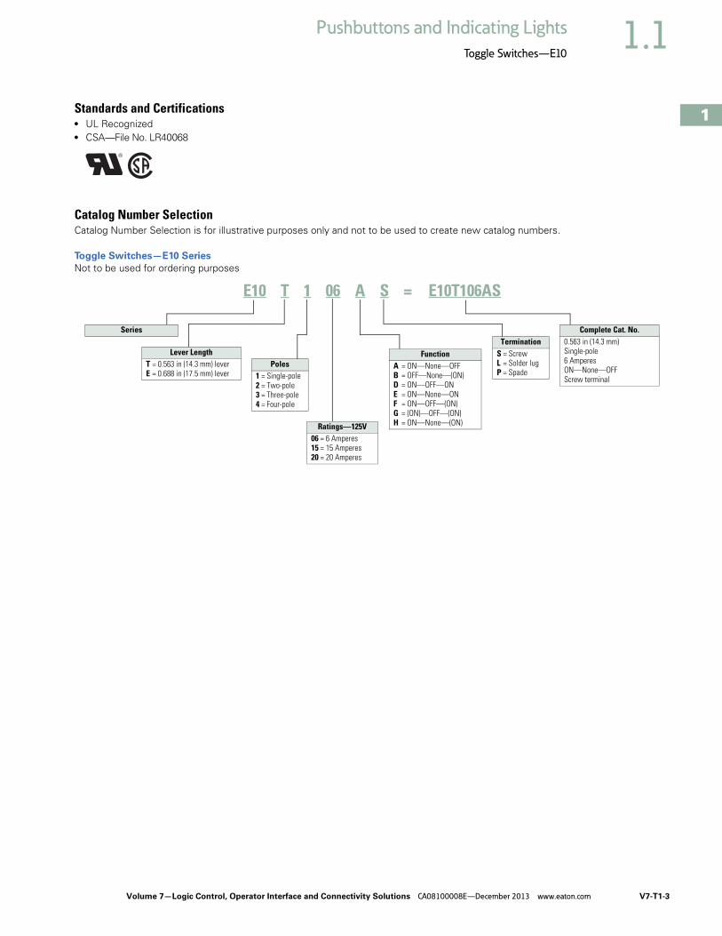
Standards and Certifications ● UL Recognized● CSA—File No. LR40068
Catalog Number SelectionCatalog Number Selection is for illustrative purposes only and not to be used to create new catalog numbers.
Toggle Switches—E10 Series
Not to be used for ordering purposes
E10 T 1 06 A S = E10T106AS
Poles1 = Single-pole2 = Two-pole3 = Three-pole4 = Four-pole
Ratings—125V06 = 6 Amperes15 = 15 Amperes20 = 20 Amperes
FunctionA = ON—None—OFFB = OFF—None—(ON)D = ON—OFF—ONE = ON—None—ONF = ON—OFF—(ON)G = (ON)—OFF—(ON)H = ON—None—(ON)
TerminationS = ScrewL = Solder lugP = Spade
Series
Lever LengthT = 0.563 in (14.3 mm) leverE = 0.688 in (17.5 mm) lever
Complete Cat. No.0.563 in (14.3 mm)Single-pole6 AmperesON—None—OFFScrew terminal

V7-T1-4 Volume 7—Logic Control, Operator Interface and Connectivity Solutions CA08100008E—December 2013 www.eaton.com
1
1
1
1
1
1
1
1
1
1
1
1
1
1
1
1
1
1
1
1
1
1
1
1
1
1
1
1
1
1
1.1 Pushbuttons and Indicating Lights
Toggle Switches—E10
Product SelectionToggle Switches
E10 Series—AC Rated—Minimum Order Quantity 10 Pieces
Note1 See Circuit Diagrams on Page V7-T1-6.
Nominal AC RatingsPolesandThrow 1
Function—Circuit with Lever In
Screw TerminalCatalog Number
0.250 in (6.4 mm)Spade TerminalCatalog Number
Solder LugCatalog Number
UPPosition
CENTERPosition
DOWNPosition—Keyway
Amperes
125V 250V
hp
50V
Single-Pole
6 3 — 1 P.S.T. ON None OFF E10T106AS E10T106AP E10T106AL
15 10 3/4 E10T115AS E10T115AP E10T115AL
20 10 3/4 E10E120AS E10E120AP E10E120AL
6 3 — 1 P.D.T. ON OFF ON E10T106DS E10T106DP —
15 10 3/4 E10T115DS E10T115DP E10T115DL
20 10 3/4 E10E120DS — —
6 3 — 1 P.D.T. ON None ON E10T106ES — —
15 10 3/4 E10T115ES E10T115EP E10T115EL
20 10 3/4 E10E120ES — —
— 10 1/2 1 P.S.T. OFF None (ON) E10T115BS E10T115BP —
1 P.D.T. ON OFF (ON) E10T115FS E10T115FP —
1 P.D.T. ON None (ON) E10T115HS E10T115HP —
1 P.D.T. (ON) OFF (ON) E10T115GS E10T115GP —
Two-Pole
6 3 — 2 P.S.T. ON None OFF E10T206AS E10T206AP —
15 10 3/4 E10T215AS E10T215AP E10T215AL
20 10 3/4 E10E220AS E10E220AP E10E220AL
6 3 — 2. P.D.T. ON OFF ON E10T206DS E10T206DP —
15 10 3/4 E10T215DS E10T215DP E10T215DL
20 10 3/4 E10E220DS E10E220DP —
6 3 — 2 P.D.T. ON None ON E10T206ES — —
15 10 3/4 E10T215ES E10T215EP E10T215EL
20 10 3/4 E10E220ES — —
15 10 1/2 2 P.S.T. OFF None (ON) E10T215BS — —
2 P.D.T. ON None (ON) E10T215HS E10T215HP —
2 P.D.T. (ON) OFF (ON) E10T215GS E10T215GP —
Three-Pole
15 10 3/4 3 P.S.T. ON None OFF E10E315AS E10E315AP —
3 P.D.T. ON OFF ON E10E315DS E10E315DP E10E315DL
3 P.D.T. ON None ON E10E315ES E10E315EP E10E315EL
Four-Pole
15 10 3/4 4 P.S.T. ON None OFF E10E415AS — E10E415AL
4 P.D.T. ON OFF ON E10E415DS — E10E415DL
4 P.D.T. ON None ON E10E415ES — E10E415EL
Two-Pole
Single-Pole
Three-Pole
Four-Pole

Volume 7—Logic Control, Operator Interface and Connectivity Solutions CA08100008E—December 2013 www.eaton.com V7-T1-5
1
1
1
1
1
1
1
1
1
1
1
1
1
1
1
1
1
1
1
1
1
1
1
1
1
1
1
1
1
1
1.1Pushbuttons and Indicating Lights
Toggle Switches—E10
Hesitation Switches
E10 Series—Special Purpose—Minimum Order Quantity 10 Pieces
Pushbuttons
E10 Series—Minimum Order Quantity 10 Pieces
Accessories
Toggle Switches Accessories—Minimum Order Quantity 100 Pieces
NotesInterlock mechanism prevents operation of lever through the center position until pressure is momentarily relieved. Designed for control and protection of reversing motors.1 See Circuit Diagrams on Page V7-T1-6.2 Rated 1/4 hp at 125V, 1/2 hp at 250V.
Nominal Ratings
Operation
Function—Circuit with Lever In…
PolesandThrow 1
Screw TerminalCatalog Number
Amperes hpUPPosition
CENTERPosition
DOWNPosition—Keyway
28Vdc
125Vac
250Vac
250Vac
15 15 10 3/4 Maintained ON OFF ON 2 P.D.T. E10E215SS
3 P.D.T. E10E315SS
4 P.D.T. E10E415SS
Nominal Ratings
PolesandThrow 1 Contacts
BushingLengthin (mm)Dim. “A”
ButtonExtensionin (mm)Dim. “B”
TypicalMaximumOperatingForce
Screw TerminalCatalog Number
Spade Terminal 0.250 in (6.4 mm)Catalog Number
Amperes hp125 Vac 250 Vac 125–
250VNO NC NO NC
6 — 3 — — 1 P.S.T. NO 0.69 (17.5) 0.53 (13.5) 0.9 lbs E10P106RS E10P106RP
0.34 (8.6) 0.25 (6.4) E10P106JS —
15 — 10 — 1/3 1 P.S.T. NO 0.69 (17.5) 0.53 (13.5) 0.9 lbs E10P115RS E10P115RP
0.34 (8.6) 0.25 (6.4) E10P115JS —
15 10 10 5 1/4 2 1 P.D.T. NO, NC 0.69 (17.5) 0.53 (13.5) 1.0 lbs E10P115LS —
Description Material/Notes Catalog Number
Hexagon locknut Zinc-chromate treated steel E10TA101
Knurled face nut Zinc-chromate treated steel E10TA102
Internal tooth lockwasher Cadmium plated steel E10TA103
Terminal screws #6-32 x 3/16 in binding head E10TA201
Spade terminal adapter—0.250 in (6.4 mm) Assembles to screw terminals E10TA202
ON-OFF indicating plate—vertical orientation Burnished nickel finish steel E10TA301
OFF-ON indicating plate—horizontal orientation Burnished nickel finish steel E10TA302
Flip-up guard for toggle switches E10TA104
Fixed shroud for toggle switches E10TA105
Heavy-Duty Hesitation Switch
One-Hole Mounted Medium-Duty, Mom. Contact
E10TA104
E10TA105

V7-T1-6 Volume 7—Logic Control, Operator Interface and Connectivity Solutions CA08100008E—December 2013 www.eaton.com
1
1
1
1
1
1
1
1
1
1
1
1
1
1
1
1
1
1
1
1
1
1
1
1
1
1
1
1
1
1
1.1 Pushbuttons and Indicating Lights
Toggle Switches—E10
Technical Data and Specifications
Toggle Switches
Hesitation Switches
Pushbutton Actuators
Circuit Diagrams
Description Specification
AC ratings 6–20A, 125 Vac3–10A, 250 VacMax. 3/4 hp at 250 Vac
DC ratings 6–20A, 28 Vdc
Electrical life 6,000 cycles make/break at switch ampere rating
Operation Slow make/slow break mechanism with butt action for AC and low voltage DC applicationsMaintained and momentary contacts
Poles/throws 1 through 4, single and double throw
Mounting One hole with threaded 0.468 in-32 bushing and 0.068 x 0.035 in (1.7 x 0.9 mm) deep keyway that serves as anti-rotational feature
Lever lengths 0.563 in (14.3 mm) or 0.688 in (17.5 mm), bright nickel plated
Terminals Screw, 0.250 in (6.4 mm) spade and solder lug
Description Specification
Operation Slow make/slow break mechanism with butt action for AC and low voltage DC applications; maintained contacts; ideal for reversing motor applications; interlock mechanism prevents operation of lever through center position until manual pressure is momentarily relieved
AC ratings 15A, 125 Vac10A, 250 VacMax. 3/4 hp at 250 Vac
DC ratings 15A, 28 Vdc
Poles/throws 2, 3 and 4, double throw only
Mounting Single-pole with threaded 0.468 in-32 bushing and 0.068 x 0.049 in (1.7 x 1.2 mm) deep keyway
Lever length 0.687 in (17.4 mm), stainless steel
Terminals Screw
Description Specification
AC ratings 6–15A, 125 Vac (NO)3–10A, 250 Vac (NO)Max. 1/3 hp at 125/250 Vac
Operation Slow make/slow break mechanismNormally open contacts
Poles/throws Single, single and double throw
Mounting One hole with 0.468 in-32 threaded bushing and 0.068 x 0.035 in (1.7 x 0.9 mm) deep keywayTwo bushing heights: 11/16 in (17.5 mm) and 11/32 in (8.7 mm)
Button extensions 17/32 in (13.5 mm) and 1/4 in (6.4 mm), bright nickel plated
Terminals Screw
SPST DPST
SPDT
DPDT
4PST3PDT 4PDT3PST

Volume 7—Logic Control, Operator Interface and Connectivity Solutions CA08100008E—December 2013 www.eaton.com V7-T1-7
1
1
1
1
1
1
1
1
1
1
1
1
1
1
1
1
1
1
1
1
1
1
1
1
1
1
1
1
1
1
1.1Pushbuttons and Indicating Lights
Toggle Switches—E10
Dimensions Approximate Dimensions in Inches (mm)
Toggle Switch Dimensions
Toggle Switch Hesitation Switch Pushbutton Actuator
Accessories
E10TA101 Hexagon Locknut
E10TA102 Knurled Face Nut
E10TA301 ON-OFF Indicating Plate—Vertical Orientation
E10TA302 ON-OFF Indicating Plate—Horizontal Orientation
Note1 Spade terminal adapters are used on 6 ampere and momentary screw terminal switches, adding 0.42 in (10.7 mm) to dimension C.
No. ofPoles Operation
BushingLengthA
LeverLengthB
Screw Terminals Spade Terminals Solder LugC D E C 1 D E C D E
1 Momentaryand maintained
0.47 (11.9)
0.56 (14.2)
1.00(25.4)
1.17 (29.7)
0.63 (16.0)
1.13(28.7)
1.13 (28.7)
0.63 (16.0)
1.00(25.4)
1.13 (28.7)
0.63 (16.0)
2 Maintained 0.47 (11.9)
0.56 (14.2)
1.06 (26.9)
1.31 (33.3)
0.75 (19.1)
1.19(30.2)
1.31 (33.3)
0.75 (19.1)
1.06 (26.9)
1.31 (33.3)
0.75 (19.1)
Momentary 0.47 (11.9)
0.56 (14.2)
1.25 (31.8)
1.31 (33.3)
0.75 (19.1)
1.31 (33.3)
1.31 (33.3)
0.75 (19.1)
1.25 (31.8)
1.31 (33.3)
0.75 (19.1)
3 Maintained 0.47 (11.9)
0.69 (17.5)
1.27 (32.3)
1.34 (34.0)
1.44 (36.6)
1.37 (34.8)
1.34 (34.0)
1.44 (36.6)
1.23 (31.2)
1.34 (34.0)
1.44 (36.6)
4 Maintained 0.47 (11.9)
0.69 (17.5)
1.20(30.5)
1.30(33.0)
1.40(35.6)
1.30(33.0)
1.34 (34.0)
1.40(35.6)
1.23 (31.2)
1.34 (34.0)
1.44(36.6)
D
E
C
A
B
1.47(37.3)
0.47-32Thread
0.07 (1.8) x 0.05 (1.3)Keyway
1.34(34)
1.25(31.8)
0.47(11.9)
0.69(17.5)
1.13(28.7)
0.47-32Thread
0.04 (1) x 0.07 (1.8)Keyway
1.13(28.7)
A
B
0.63(16)
0.63(16)
0.08(2) 0.63
(16)
0.07(1.8)
0.63(16)
0.06(1.5)
0.03(.8)
1.0(25.4)
ON
OFF
ON
OFF

V7-T1-8 Volume 7—Logic Control, Operator Interface and Connectivity Solutions CA08100008E—December 2013 www.eaton.com
1
1
1
1
1
1
1
1
1
1
1
1
1
1
1
1
1
1
1
1
1
1
1
1
1
1
1
1
1
1
1.2 Pushbuttons and Indicating Lights
Environmentally Sealed Toggle Switches—E10E
Toggle Switches—E10E ContentsDescription Page
Environmentally Sealed Toggle Switches—E10EProduct Selection
Molded-In Screw Terminal . . . . . . . . . . . . . V7-T1-9
Econoswitch . . . . . . . . . . . . . . . . . . . . . . . . V7-T1-9
Switch Guard . . . . . . . . . . . . . . . . . . . . . . . . V7-T1-9
Technical Data and Specifications . . . . . . . . . . V7-T1-10
Dimensions . . . . . . . . . . . . . . . . . . . . . . . . . . . V7-T1-11
Product DescriptionDesigned for general purpose and OEM applications, this line of toggle switches provides a high IP68 rating for demanding environments.
FeaturesMolded-In Screw Terminal● Completely sealed against
dust, moisture and other contaminants
● One-hole mounted bushing for easy installation
● Multi-circuits offered● Two- and three-position
with maintained and momentary action
● Molded-in terminal inserts and terminals numbers
● Single- and two-pole circuitry
Econoswitch● Environmentally sealed● Single- and two-pole
circuitry● One-hole mounting for
easy installation● Multi-circuits● Two- and three-position
with maintained and momentary action
● Three types of termination offered as standard
Switch Guard● For use with two-position
switch● Cover closure transfers
switch toggle lever to OFF position
● One-hole mounted mounting style
● Cover is molded out of red thermoset molding material
● Guard cover is spring-loaded to either close or lock in open position
● Prevents accidental operation at switches
OptionsNote: Contact your local Eaton Sales Representative for more information. ● Non-UL Recognized
devices● Alternate toggle levers● Locking toggle levers● Rocker buttons
● Special mounting hardware● Mounting hardware
furnished assembled● Terminal screws furnished
assembled● Special circuits● Panel seal, part number
32-341● Spade terminal adapters
available
Standards and Certifications ● UL—File number E15346;
Guide card number is WOYR2
● CSA—LR40068, class number 6241
UL and CSA Nominal Ratings
Catalog Number 125 Vac 250 Vac
Amperes
E10E118xx 18 9
E10E218xx 18 9
Single-Phase hp
E10E118xx 1/4 1/2
E10E218xx 1/2 1
Three-Phase hp
E10E118xx — —
E10E218xx — —

Volume 7—Logic Control, Operator Interface and Connectivity Solutions CA08100008E—December 2013 www.eaton.com V7-T1-9
1
1
1
1
1
1
1
1
1
1
1
1
1
1
1
1
1
1
1
1
1
1
1
1
1
1
1
1
1
1
1.2Pushbuttons and Indicating Lights
Environmentally Sealed Toggle Switches—E10E
Product SelectionMolded-In Screw Terminal
E10E Series—Molded-In Screw Terminal
Econoswitch
E10E Series—Econoswitch
Switch Guard
E10E Series—Switch Guard
Note1 Momentary contact.
Circuit with Lever Position
Catalog Number
Up CenterDown(Keyway)Nominal AC Ratings
Amperes Single-Phase hp Three-Phase hp
125V 250V 125V 250V 125/250V
Single-Pole
18 9 1/4 1/2 — ON OFF ON E10E118DM
ON NONE OFF E10E118AM
ON NONE ON E10E118EM
Two-Pole
18 9 1/2 1 — ON OFF ON E10E218DM
ON NONE OFF E10E218AM
ON NONE ON E10E218EM
Type of Operation
Circuit with Lever Position
Screw TerminalCatalog Number
Solder LugTerminalCatalog Number
Spade TerminalCatalog Number
Current Ratings—AmperesUp Center
Down(Keyway)28 Vdc 115 Vac, 60 or 400 Hz
LampLoad
ResistiveLoad
InductiveLoad
LampLoad
ResistiveLoad
InductiveLoad
Single-Pole
Maintained 5 20 15 3 15 10 ON OFF ON E10E118DS E10E118DL E10E118DP
Maintained 5 20 15 3 15 10 ON NONE OFF E10E118AS E10E118AL E10E118AP
Maintained 5 20 15 3 15 10 ON NONE ON E10E118ES E10E118EL E10E118EP
Momentary 4 15 10 2 15 7 ON 1 OFF ON 1 E10E118GS E10E118GL E10E118GP
Momentary 4 15 10 2 15 7 OFF NONE ON 1 E10E118BS E10E118BL E10E118BP
Two-Pole
Maintained 7 20 15 4 15 15 ON OFF ON E10E218DS E10E218DL E10E218DP
Maintained 7 20 15 4 15 15 ON NONE OFF E10E218AS E10E218AL E10E218AP
Maintained 7 20 15 4 15 15 ON NONE ON E10E218ES E10E218EL E10E218EP
Momentary 5 18 10 2 11 8 ON 1 OFF ON 1 E10E218GS E10E218GL E10E218GP
Momentary 5 18 10 2 11 8 OFF NONE ON 1 E10E218BS E10E218BL E10E218BP
Catalog Number
Switch Guard E10TA104
Single-Pole
Two-Pole
Single-Pole
Two-Pole
Switch Guard
V7-T1-10 Volume 7—Logic Control, Operator Interface and Connectivity Solutions CA08100008E—December 2013 www.eaton.com
1
1
1
1
1
1
1
1
1
1
1
1
1
1
1
1
1
1
1
1
1
1
1
1
1
1
1
1
1
1
1.2 Pushbuttons and Indicating Lights
Environmentally Sealed Toggle Switches—E10E
Technical Data and Specifications
E10E Series—Molded-In Screw Terminal
E10E Series—Econoswitch
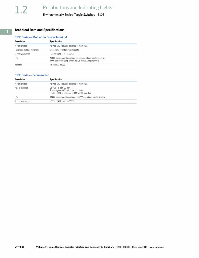
Description Specification
Watertight seal Per MIL-STD-108E and designed to meet IP68
Thermoset molding materials Meet flame retardant requirements
Temperature range –50° to 150°F (–46° to 66°C)
Life 20,000 operations at rated load; 40,000 operations mechanical life; 6,000 operations at hp ratings per UL and CSA requirements
Bushings 15/32 in-32 thread
Description Specification
Watertight seal Per MIL-STD-108E and designed to meet IP68
Type of terminal Screws—6-32 UNC-22ASolder lug—0.125 in (3.17 mm) dia. holeSpade—0.250 in (6.35 mm) x 0.032 in (0.81 mm) thick
Life 50,000 operations at rated load; 100,000 operations mechanical life
Temperature range –50° to 150°F (–46° to 66°C)

Volume 7—Logic Control, Operator Interface and Connectivity Solutions CA08100008E—December 2013 www.eaton.com V7-T1-11
1
1
1
1
1
1
1
1
1
1
1
1
1
1
1
1
1
1
1
1
1
1
1
1
1
1
1
1
1
1
1.2Pushbuttons and Indicating Lights
Environmentally Sealed Toggle Switches—E10E
DimensionsApproximate Dimensions in Inches (mm)
Single-Pole Molded-In Screw Terminal E10E Series
Toggle Switch Panel Cutout
Two-Pole Molded-In Screw Terminal E10E Series
0.432 (10.97)
0.076(1.93)
Keyway
1.18(29.9)Max.
0.250(6.35)
#6-32 Terminal Screwwith Internal Tooth
Lockwasher (SEMS)
0.635(16.13)Max.
0.380(9.65)Typ.
1.270 (32.26) Max.
15/32-32 UN-2AThread to Within
0.060 (1.52)of Shoulder
1 2 3
16.5°
33°
0.240 (6.10)Dia.
0.690(17.53)
0.470(11.94)
15/32 Dia. Bushing
0.375(9.52) 0.130
(3.30) 0.062(1.57)
0.480 (12.19)Dia. Hole
Locking Ring Keyway
0.445(11.30)
0.480 (12.19)Dia. Hole
0.690(17.53)
0.470(11.94)
1.100(27.94)Max.
0.130(3.30)
0.250(6.35)
0.130(3.30)
0.380(9.65)
0.910(23.11)Max.
1.370(34.80)Max.
0.076(1.93)
Keyway
#6-32 Terminal Screwwith Internal Tooth
Lockwasher (SEMS)
15/32-32 UN-2AThread to Within
0.060 (1.52)of Shoulder
1 2 3
4 5 6
0.432 (10.97)
16.5°
33°
0.240 (6.10)Dia.
0.380(9.65)Typ.
1.340 (34.04) Max.

V7-T1-12 Volume 7—Logic Control, Operator Interface and Connectivity Solutions CA08100008E—December 2013 www.eaton.com
1
1
1
1
1
1
1
1
1
1
1
1
1
1
1
1
1
1
1
1
1
1
1
1
1
1
1
1
1
1
1.2 Pushbuttons and Indicating Lights
Environmentally Sealed Toggle Switches—E10E
Approximate Dimensions in Inches (mm)
Single-Pole Econoswitch E10E Series
Two-Pole Econoswitch E10E Series
#6-32 UNC-2ATerminal Screw,
SEMS0.125 (3.17)Dia. Hole
0.250 x 0.032(6.35) x (0.81)
Thick
15/32-32 UN-2AThread to Within
0.060 (1.52)of Shoulder
0.240 (6.10)Dia.
0.432 (10.97)
0.076(1.93)
Keyway
21 3 21 3 21 3
Screw Terminal Solder Lug Spade Terminal
0.690(17.53)
0.470(11.94)
1.30(33.0)Max.
1.28(32.5)Max.
1.51(38.4)Max.
0.594(15.09)
1.25 (31.75)
33°
16.5°
0.432 (10.97)
0.076(1.93)
Keyway
33°
0.125 (3.17)Dia. Hole
0.250 x 0.032(6.35) x (0.81)
Thick
1.55(39.4)Max.
Screw Terminal Solder Lug Spade Terminal
0.89(22.6)
1.32 (33.5)
#6-32 UNC-2ATerminal Screw,
SEMS
15/32-32 UN-2AThread to Within
0.060 (1.52)of Shoulder
0.240 (6.10)Dia.
16.5°
0.690(17.53)
0.468(11.89)
1.34(34.1)Max.
1.32(33.5)Max.

Volume 7—Logic Control, Operator Interface and Connectivity Solutions CA08100008E—December 2013 www.eaton.com V7-T1-13
1
1
1
1
1
1
1
1
1
1
1
1
1
1
1
1
1
1
1
1
1
1
1
1
1
1
1
1
1
1
1.2Pushbuttons and Indicating Lights
Environmentally Sealed Toggle Switches—E10E
Approximate Dimensions in Inches (mm)
Switch Guard
15/32-32 UN-2AThread to Within
0.060 (1.52)of Shoulder
Rivet
Switch(Ref.)
Red-MoldedPlastic
Closed
Steel
Open
0.240 (6.10)Dia.
33°
0.840(21.34)
0.468(11.89)
0.688(17.48)Max.
0.062(1.57)
0.031(0.79)
1.062(26.97)
1.547 (39.29)Rad.
0.475(12.07)
Dia.
0.688(17.48)
1.093(27.76)Max.
0.032(0.81)
1.635 (41.53) Max.
1.830 (46.48) Max.
0.750(19.05)Max.

V7-T1-14 Volume 7—Logic Control, Operator Interface and Connectivity Solutions CA08100008E—December 2013 www.eaton.com
1
1
1
1
1
1
1
1
1
1
1
1
1
1
1
1
1
1
1
1
1
1
1
1
1
1
1
1
1
1
1.3 Pushbuttons and Indicating Lights
Pushbutton Control Stations—Assembled
Pushbutton Control Stations ContentsDescription Page
Pushbutton Control Stations—AssembledFeatures . . . . . . . . . . . . . . . . . . . . . . . . . . . . . . V7-T1-15
Product Selection M22 Assembled Control Stations . . . . . . . . V7-T1-16
Commercial Control Stations . . . . . . . . . . . V7-T1-17
General Purpose Control Stations . . . . . . . . V7-T1-18
Special Purpose Control Stations . . . . . . . . V7-T1-19
10250H Series Heavy-Duty Control Stations . . . . . . . . . . . . . . . . . . . . V7-T1-20
10250T Series Heavy-Duty 30.5 mm Control Stations . . . . . . . . . . . . . . . . . . . . V7-T1-21
Class I Division 2 10250T Series Heavy-Duty 30.5 mm Control Stations . . . . . . . . . . . . V7-T1-22
Class I Division 2 E34 Series Corrosion Resistant 30.5 mm Control Stations . . . . V7-T1-23
Accessories . . . . . . . . . . . . . . . . . . . . . . . . . . . V7-T1-23
Custom Assembled Stations Specification Form . . . . . . . . . . . . . . . . . . . . . V7-T1-24
Renewal Parts . . . . . . . . . . . . . . . . . . . . . . . . . V7-T1-26
Technical Data and Specifications . . . . . . . . . . V7-T1-28
Dimensions. . . . . . . . . . . . . . . . . . . . . . . . . . . . V7-T1-28
Product DescriptionM22 Assembled Control Stations● M22 series operators● Available in horizontal and
vertical configurations● Impact resistant
polycarbonate enclosures● Optional yellow covers● Base mounting contact
blocks and light units for quick wiring and vibration resistance
Commercial Control Stations● 10250T series operators● Full front label● Specific function labels on
front of enclosure
General Purpose Control Stations● Construction grade● General purpose wall
mount● Popular with contractors● UL (NEMA) Type 1
Special Purpose Control Stations● Standard grade● Polyester enclosure● UL (NEMA) Type 3, 3R, 4,
4X, 13
10250H Series Heavy-Duty Control Stations● 10250H Series operators● Dark brown polyester
enclosure● Protective rubber gaskets
provide NEMA 3S rating on pushbuttons
● Top and bottom 3/4 in NPT conduit entrances
● Includes alternate legend plates and spare mounting screws
10250T Series Heavy-Duty 30.5 mm Control Stations● 10250T Series operators● ASA 61 gray die-cast zinc
enclosures● Surface or flush mounting● Single 3/4 in NPT conduit
entrance on one and two element stations
● Single 1 in NPT conduit entrance on three element stations
Class I Division 2 10250T Series Heavy-Duty 30.5 mm Control Stations● 10250T Series operators● Factory sealed contact
blocks● Die-cast, polyester or
stainless steel enclosures● Approved for NEC Class I
Division 2, Groups B, C and D or Class I Zone 2 Group IIB plus Hydrogen type hazardous locations
Class I Division 2 E34 Series Corrosion Resistant 30.5 mm Control Stations● E34 Series operators● Factory sealed contact
blocks● Die-cast, polyester or
stainless steel enclosures● Approved for NEC Class I
Division 2 Groups B, C and D or Class I Zone 2 Group IIB plus Hydrogen type hazardous locations
Volume 7—Logic Control, Operator Interface and Connectivity Solutions CA08100008E—December 2013 www.eaton.com V7-T1-15
1
1
1
1
1
1
1
1
1
1
1
1
1
1
1
1
1
1
1
1
1
1
1
1
1
1
1
1
1
1
1.3Pushbuttons and Indicating Lights
Pushbutton Control Stations—Assembled
FeaturesM22 Assembled Control Stations● IP66, UL (NEMA) Type 4X,
13● Impact resistant
polycarbonate enclosures● Optional yellow cover● 25% smaller depth than
most competitor enclosures
● Base mounting contact blocks and light units for faster wiring and vibration resistance
Commercial Control Stations● ASA 61 gray die-cast zinc
enclosures● Pre-assembled and labeled
for functions such as “Fuel Shut-Off”
● Great for commercial applications
General Purpose Control Stations● Construction grade● General purpose wall
mount● Popular with contractors● UL (NEMA) Type 1
Special Purpose Control Stations● Standard grade● Polyester enclosure● UL (NEMA) Type 3, 3R, 4,
4X, 13
10250H Series Heavy-Duty Control Stations● Industrial grade● Extra heavy-duty● Polyester enclosure● Booted buttons● Outdoor installation● UL (NEMA) Type 3, 3R, 3S,
4, 4X, 12, 13
10250T Series Heavy-Duty 30.5 mm Control Stations● 30.5 mm operators● Industrial grade● Zinc die cast enclosure● Popular with industrial end
users● UL (NEMA) Type 4, 4X, 12,
13
Class I Division 2 Control Stations● Available with 10250T or
E34 30.5 mm operators● Zinc die cast, polyester or
stainless steel enclosures● Factory-sealed contact
blocks● Popular with industrial end
users● UL (NEMA) Type 4, 4X, 12,
13● NEC Class I Division 2
Groups B, C and D

V7-T1-16 Volume 7—Logic Control, Operator Interface and Connectivity Solutions CA08100008E—December 2013 www.eaton.com
1
1
1
1
1
1
1
1
1
1
1
1
1
1
1
1
1
1
1
1
1
1
1
1
1
1
1
1
1
1
1.3 Pushbuttons and Indicating Lights
Pushbutton Control Stations—Assembled
Product SelectionM22 Assembled Control Stations
One Element Control Stations
Two Element Control Stations
Three Element Control Stations
NotesFor assembled control stations not found in this selection, please contact the Eaton Technical Resource Center at 1-877-ETN CARE (386-2273) or [email protected].
1 Contact block configuration.
Orientation Description Color 1 InscriptionEnclosure Cover Color Catalog Number
Horizontal 40 mm mushroom head push-pull emergency stop operator Red NC — Yellow M22-C1-M1H
Horizontal 40 mm illuminated mushroom head push-pull emergency stop operator, 85–264 Vac
Red NO-NC — Yellow M22-C1-M2H
Horizontal 40 mm mushroom head twist-to-release emergency stop operator Red NC — Yellow M22-C1-M3H
Horizontal 40 mm mushroom head key-release emergency stop operator Red NC — Yellow M22-C1-M4H
Horizontal Flush pushbutton Green NO Gray M22-C1-M5H
Horizontal Flush pushbutton Green NO START Gray M22-C1-M6H
Horizontal Extended pushbutton Red NC Gray M22-C1-M7H
Horizontal Extended pushbutton Red NC STOP Gray M22-C1-M8H
Horizontal Key-operated selector switch, two-position maintained — NO OFF-ON Gray M22-C1-M9H
Horizontal Knob type selector switch, three-position maintained — 2NO HAND 0 AUTO Gray M22-C1-M10H
Horizontal Double pushbutton Green NO START Gray M22-C1-M11H
Red NC STOP
OrientationElement 1Description Color 1 Inscription
Element 2Description Color 1 Inscription
Enclosure Cover Color Catalog Number
Horizontal Extended pushbutton Red NC Flush pushbutton Green NO Gray M22-C2-M1H
Vertical Flush pushbutton Green NO START Extended pushbutton Red NC STOP Gray M22-C2-M2V
Vertical Flush pushbutton Black NO FORWARD Flush pushbutton Black NO REVERSE Gray M22-C2-M3V
OrientationElement 1Description Color 1 Inscription
Element 2Description Color 1 Inscription
Element 3Description Color 1 Inscription
Enclosure Cover Color Catalog Number
Horizontal Extended pushbutton
Red NC Indicatinglight
White 85–264 Vac
— Flush pushbutton
Green NO Gray M22-C3-M1H
Vertical Indicating light
White 85–264 Vac
— Flush pushbutton
Green NO START Extended pushbutton
Red NC STOP Gray M22-C3-M2V
Horizontal Flush pushbutton
Green NO Extended pushbutton
Red NC Flush pushbutton
Green NO Gray M22-C3-M3H
Vertical Flush pushbutton
Black NO OPEN Extended pushbutton
Red NC STOP Flush pushbutton
Black NO CLOSE Gray M22-C3-M4V
Vertical Flush pushbutton
Black NO FORWARD Flush pushbutton
Red NC STOP Flush pushbutton
Black NO REVERSE Gray M22-C3-M5V
Vertical Flush pushbutton
Black NO UP Flush pushbutton
Red NC STOP Flush pushbutton
Black NO DOWN Gray M22-C3-M6V

Volume 7—Logic Control, Operator Interface and Connectivity Solutions CA08100008E—December 2013 www.eaton.com V7-T1-17
1
1
1
1
1
1
1
1
1
1
1
1
1
1
1
1
1
1
1
1
1
1
1
1
1
1
1
1
1
1
1.3Pushbuttons and Indicating Lights
Pushbutton Control Stations—Assembled
Commercial Control Stations
Key Specifications● 30.5 mm (10250T series)
operators● ASA 61 gray die-cast zinc
enclosures● Industrial grade● UL® Type 4, 4X, 12, 13● Single 3/4 in NPT conduit
entrance● Dimensions—in (mm)
● Enclosure:3.88 W x 4.00 H x 3.00 D(98.6 x 101.6 x 76.3)
● Operator:1.63 D (to enclosure) x1.50 diameter (41.4 x 38.1)
What is included?Eaton’s pre-assembled, enclosed emergency stop pushbutton stations include an operator, an enclosure, contact blocks and a variety of unique labels. Each label has white lettering on a red background indicating the function and red lettering on a white background indicating the operator type.
Available Catalog Numbers
Additional Contact Blocks
(Sold Separately)
Note1 Includes 1NO-1NC contact block.
Catalog Number 1 Operator
Enclosure Color Label
10250T5B62-S101 Push-Pull Gray EMERGENCY STOP
10250T5B62-S102 Push-Pull Gray EMERGENCY SHUT-OFF
10250T5B62-S103 Push-Pull Gray EMERGENCY GENERATOR STOP
10250T5B62-S104 Push-Pull Gray EMERGENCY HVAC SHUT-DOWN
10250T5B62-S105 Push-Pull Gray EMERGENCY ELECTRICAL DISCONNECT
10250T5B62-S106 Push-Pull Gray EMERGENCY BOILER SHUT-DOWN
10250T5B62-S107 Push-Pull Gray EMERGENCY CHILLER STOP
10250T5B62-S108 Push-Pull Gray EMERGENCY FUEL SHUT-OFF
10250T5B62-S109 Push-Pull Gray EMERGENCY REFRIGERATION STOP
10250T5B62-S110 Push-Pull Gray EMERGENCY POWER OFF
10250T5B62-S111 Push-Pull Gray EMERGENCY GAS SHUT-OFF
10250T5B62-S112 Push-Pull Gray EMERGENCY VENTILATION SHUT-DOWN
10250T5B62-S113 Push-Pull Gray GENERATOR
Catalog NumberCircuit Configuration
10250T51 1NC
10250T53 1NO
10250T1 NO-NC
10250T3 2NC
10250T2 2NO

V7-T1-18 Volume 7—Logic Control, Operator Interface and Connectivity Solutions CA08100008E—December 2013 www.eaton.com
1
1
1
1
1
1
1
1
1
1
1
1
1
1
1
1
1
1
1
1
1
1
1
1
1
1
1
1
1
1
1.3 Pushbuttons and Indicating Lights
Pushbutton Control Stations—Assembled
General Purpose Control Stations
Type N Control Stations—UL (NEMA) Type 1
Note1 Round button.
ContactSymbol Button Type/Color Legends Catalog Number
One Element Enclosure Type
Flush/green START 10250H5100
Flush/red STOP 10250H5101
Extended/red STOP 10250H5104
Palm operated/black None 10250H89 1
Three-position selectorswitch/black knob
RUN/OFF/AUTO 10250H289 1
Two Element Enclosure Type
Flush/red START/STOP 10250H5200
Flush/greenextended/red
START/STOP 10250H5207
Flush/black (all) RAISE/LOWER 10250H5201
FOR/REV 10250H5202
OPEN/CLOSE 10250H5203
UP/DOWN 10250H5204
HIGH/LOW 10250H5205
FAST/SLOW 10250H5208
Three Element Enclosure Type
Flush/black (all) FOR/REV/STOP 10250H5300
UP/DOWN/STOP 10250H5301
RAISE/LOWER/STOP 10250H5302
OPEN/CLOSE/STOP 10250H5303
FAST/SLOW/STOP 10250H5304
110/220V neon indicating light START/STOP
Clear—flush/green; flush/red 10250H5310
Red—flush/green; flush/red 10250ED853
Amber—flush/green; flush/red 10250ED853-2
Selector Switch
Two Button Station
Three Button Station
Three Button Station with Indicating Light
Single Button Station with Padlock Attachment Accessory

Volume 7—Logic Control, Operator Interface and Connectivity Solutions CA08100008E—December 2013 www.eaton.com V7-T1-19
1
1
1
1
1
1
1
1
1
1
1
1
1
1
1
1
1
1
1
1
1
1
1
1
1
1
1
1
1
1
1.3Pushbuttons and Indicating Lights
Pushbutton Control Stations—Assembled
Type N Control Stations—Open Type Construction (No Cover)
Special Purpose Control Stations
Special Purpose Control Stations—UL (NEMA) Type 3, 3R, 4, 4X, 13
Note1 No legend on buttons. Specify any standard legend.
ContactSymbol Button Type/Color Legends Catalog Number
One Element Enclosure Type
Three-position selectorswitch/black knob
RUN/OFF/AUTO 10250H2538
Two Element Enclosure Type
Flush/green START/STOP 10250H2747
Flush/black (all)mech. interlocked
None 1 10250H2544
ContactSymbol Feature Legends Catalog Number
One Element Pushbutton Type
Flush START 10250H2738
STOP 10250H658
With lock hasp STOP 10250H665
Two Element Pushbutton Type
Flush START/STOP 10250H364
With lock hasp START/STOP 10250H671
Buttons interlocked FAST/SLOW 10250ED664
FOR/REV 10250H2740
UP/DOWN 10250H2741
OPEN/CLOSE 10250H2742
Mechanically Interlocked Pushbuttons
Two Button Station
Selector Switch
10250H_
10250H_

V7-T1-20 Volume 7—Logic Control, Operator Interface and Connectivity Solutions CA08100008E—December 2013 www.eaton.com
1
1
1
1
1
1
1
1
1
1
1
1
1
1
1
1
1
1
1
1
1
1
1
1
1
1
1
1
1
1
1.3 Pushbuttons and Indicating Lights
Pushbutton Control Stations—Assembled
10250H Series Heavy-Duty Control Stations
Type H Control Stations—UL (NEMA) Type 3, 3S, 4, 4X, 12, 13
Element Type Feature Circuit
AssembledLegendPlate
UnassembledAlternateLegend Plate Catalog Number
One Element
Pushbuttons Without padlock hasp 1NO-1NC JOG START 10250H1881
STOP
RUN
With padlock hasp 1NC STOP — 10250H4239
Knob selector switch
Two-position 1NO-1NC OFF/ON — 10250H4526
Three-position 1NO-1NC MAN/OFF/AUTO — 10250H4527
Two Element
Pushbuttons Standard 1NO-2NC START/STOP — 10250H1884
2NO-2NC RAISE/LOWER FORWARD 10250H1885
REVERSE
OPEN
CLOSE
Standard and standard with padlock hasp
1NO-2NC START/STOP — 10250H4240
Three Element
Pushbuttons Standard 2NO-3NC FOR/REV/STOP START OPEN 10250H1890
Two standard and standard withpadlock hasp
JOG CLOSE 10250H4241
RAISE FAST
LOWER SLOW
Indicatinglight andpushbuttons
120V Light-red lensand two plain
1NO-2NC MOTORRUNNINGSTART/STOP
— 10250H1913
10250H_
10250H_
10250H_

Volume 7—Logic Control, Operator Interface and Connectivity Solutions CA08100008E—December 2013 www.eaton.com V7-T1-21
1
1
1
1
1
1
1
1
1
1
1
1
1
1
1
1
1
1
1
1
1
1
1
1
1
1
1
1
1
1
1.3Pushbuttons and Indicating Lights
Pushbutton Control Stations—Assembled
10250T Series Heavy-Duty 30.5 mm Control Stations
Complete Assembled Stations—UL (NEMA) Type 4, 4X, 12, 13
Break Glass Kit
Notes1 Stop buttons are red—all others are black.2 NEMA 4–13, if properly mounted on a flat surface. Consists of front plate, legend, operator and contact blocks.3 Break glass stations will not function with Normally Open contact blocks.4 Lock is 10250TA2.5 Uses deep cover instead of shallow cover. Switch component is 10250TA67—mechanically interlocked operators.6 Shown assembled to contact block (contact block supplied separately).
Element Type 1 FeaturesContactBlock(s) Legend
Surface Mounting Catalog Number
Flush Mounting 2Catalog Number
Break Glass Station
Break glass station 3 Gray enclosure NC (logic level) EMERG. OFF 10250TGS —
Red enclosure 10250TGR —
One Element
Pushbutton Standard NO-NC START 10250T3516 10250T3573
NC STOP 10250T3518 10250T3575
NO-NC None 10250T3540 10250T3597
Mushroom head NO-NC START 10250T3517 10250T3574
NC STOP 10250T3519 10250T3576
With lock hasp 4 NC STOP 10250T3520 10250T3577
Selector switch Two-positionblack knob
NO-NC OFF/ON 10250T3523 10250T3580
Three-positionblack knob
2NO MAN/OFF/AUTO 10250T3524 10250T3581
Push-pullthree-position
Momentaryred button
2NC START/STOP 10250T3545 10250T3602
Two Element
Pushbuttons Standard 1NO-2NC START/STOP 10250T3525 10250T3582
2NO-2NC RAISE/LOWER 10250T3672 10250T3673
2NO-2NC None 10250T3541 10250T3598
With lock hasp 4 1NO-2NC START/STOP 10250T3542 10250T3599
Standard and mushroom head 1NO-2NC START/STOP 10250T3526 10250T3583
Standard with maintained contact 5
NO-NC START/STOP 10250T3528 10250T3585
Plus NC
Three Element
Pushbuttons Standard 2NO-3NC FOR, REV, STOP 10250T3532 10250T3589
2NO-3NC UP, DOWN, STOP 10250T3615 —
2NO-3NC OPEN, CLOSE, STOP 10250T3614 —
2NO-3NC None, None, STOP 10250T3543 10250T3600
Two standard and with lock hasp 2NO-3NC None, None, STOP 10250T3544 10250T3601
Indicating light(transformer type) and pushbuttons
Red lens — 120V 1NO-2NC MOTOR RUN,START/STOP
10250T3536 10250T3593
Red lens — 240V 10250T3537 10250T3594
Red lens — 480V 10250T3538 10250T3595
Red lens — 600V 10250T3539 10250T3596
Description Catalog Number
Operator with hammer and five glass discs 10250TBG
Glass discs only (5) 10250TGL
Break Glass Station
One Element
Two Element
Three Element
Break Glass Operator 6

V7-T1-22 Volume 7—Logic Control, Operator Interface and Connectivity Solutions CA08100008E—December 2013 www.eaton.com
1
1
1
1
1
1
1
1
1
1
1
1
1
1
1
1
1
1
1
1
1
1
1
1
1
1
1
1
1
1
1.3 Pushbuttons and Indicating Lights
Pushbutton Control Stations—Assembled
Class I Division 2 10250T Series Heavy-Duty 30.5 mm Control Stations
Complete Assembled Stations—UL (NEMA) Type 4, 4X, 12, 13; NEC Class I Division 2, Groups B, C and D
Contact Symbol
Button Type/Color
Legend Marking
Die Cast Enclosure Catalog Number
Polyester Molded EnclosureCatalog Number
Stainless Steel EnclosureCatalog Number
Single Pushbutton
Flush/green START 10250T7003 10250T7003P 10250T7003S
Extended/red STOP 10250T7005 10250T7005P 10250T7005S
Alum. jumbomushroom/red
EMER. STOP(engraved button)
10250T7007 10250T7007P 10250T7007S
Flush/black No legend 10250T7009 10250T7009P 10250T7009S
Two Pushbuttons
Flush/green START 10250T7023 10250T7023P 10250T7023S
Extended/red STOP
Flush/black No legend 10250T7025 10250T7025P 10250T7025S
Flush/black No legend
Single Pilot Light—Two Pushbuttons
120 Vac red No legend 10250T7033 10250T7033P 10250T7033S
Flush/green START
Extended/red STOP
120 Vac red No legend 10250T7035 10250T7035P 10250T7035S
Flush/black
Flush/black
Three-Position Selector Switch
Maintainedknob/black
HAND/OFF/AUTO 10250T7011 10250T7011P 10250T7011S
Maintainedknob/black
No legend 10250T7013 10250T7013P 10250T7013S
Single Pushbutton Maintained
Push-pull with jumbomushroom/red
EMER. STOP(engraved button)
10250T7019 10250T7019P 10250T7019S
10250T7007
10250T7023P
10250T7033S
1NO
1NC
Each Button1NC
1NO
Each Button1NC
1NO
2NC
2NO
PullOX
PushXO
1NO1NC
Volume 7—Logic Control, Operator Interface and Connectivity Solutions CA08100008E—December 2013 www.eaton.com V7-T1-23
1
1
1
1
1
1
1
1
1
1
1
1
1
1
1
1
1
1
1
1
1
1
1
1
1
1
1
1
1
1
1.3Pushbuttons and Indicating Lights
Pushbutton Control Stations—Assembled
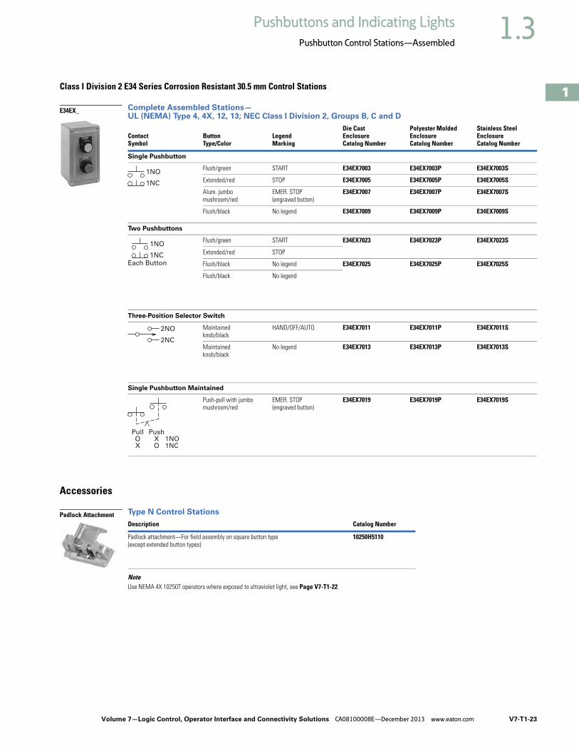
Class I Division 2 E34 Series Corrosion Resistant 30.5 mm Control Stations
Complete Assembled Stations—UL (NEMA) Type 4, 4X, 12, 13; NEC Class I Division 2, Groups B, C and D
Accessories
Type N Control Stations
NoteUse NEMA 4X 10250T operators where exposed to ultraviolet light, see Page V7-T1-22.
Contact Symbol
Button Type/Color
Legend Marking
Die Cast Enclosure Catalog Number
Polyester Molded EnclosureCatalog Number
Stainless Steel EnclosureCatalog Number
Single Pushbutton
Flush/green START E34EX7003 E34EX7003P E34EX7003S
Extended/red STOP E34EX7005 E34EX7005P E34EX7005S
Alum. jumbomushroom/red
EMER. STOP(engraved button)
E34EX7007 E34EX7007P E34EX7007S
Flush/black No legend E34EX7009 E34EX7009P E34EX7009S
Two Pushbuttons
Flush/green START E34EX7023 E34EX7023P E34EX7023S
Extended/red STOP
Flush/black No legend E34EX7025 E34EX7025P E34EX7025S
Flush/black No legend
Three-Position Selector Switch
Maintainedknob/black
HAND/OFF/AUTO E34EX7011 E34EX7011P E34EX7011S
Maintainedknob/black
No legend E34EX7013 E34EX7013P E34EX7013S
Single Pushbutton Maintained
Push-pull with jumbomushroom/red
EMER. STOP(engraved button)
E34EX7019 E34EX7019P E34EX7019S
Description Catalog Number
Padlock attachment—For field assembly on square button type (except extended button types)
10250H5110
E34EX_
1NO
1NC
Each Button1NC
1NO
2NC
2NO
PullOX
PushXO
1NO1NC
Padlock Attachment

V7-T1-24 Volume 7—Logic Control, Operator Interface and Connectivity Solutions CA08100008E—December 2013 www.eaton.com
1
1
1
1
1
1
1
1
1
1
1
1
1
1
1
1
1
1
1
1
1
1
1
1
1
1
1
1
1
1
1.3 Pushbuttons and Indicating Lights
Pushbutton Control Stations—Assembled
Custom Assembled Stations Specification FormOrdering Instructions
Step 1Copy this ordering guide from catalog.
Step 2Specify 10250T or E34 pushbutton lines in the corresponding box on the following page.
Step 3Check back of panel dimensions—specify single or double depth enclosure in the corresponding box on the following page.
Step 4Specify enclosure catalog number and price in the corresponding box on the following page. Enclosures can be found on Pages V7-T1-116, V7-T1-233 and V7-T1-283. For pricing, reference the most recent PAD or VISTA-line.
Step 5Specify catalog numbers for desired operator, legend plate, light unit, accessory and contact block(s) for each location in the enclosure in the corresponding box on the following page. (See position locations on this page.)
Position Locations
Step 6For non-standard legends, specify legend desired, letter size and location on the layout sketches on the following page. For limitations see Page V7-T1-232. For pricing, use the blank legend catalog number and “STAMP” Suffix (Ex.: 10250TS36STAMP) and reference the most recent PAD or VISTA-line.
Example: 10250TS36
Special Legend for Position #_______
Step 7Fax Sheet 2 of this form to Eaton’s TRC, Technical Resource Center, at 828-651-0549 to the attention of—Custom Stations Order or email to [email protected].
Within a few days you will receive a confirmation fax with the custom station part number and price.
Step 8Place your order over the VISTA System.
For Selector and Roto-Push Operators
10250T or E34For single contact blocks or 1NO-1NC contact blocks, the mounting position of contacts must be specified. For example: If a 1NO-1NC contact block is required, specify if NO is to be mounted in Top A position or Bottom B position.
10250T Pages V7-T1-182 to V7-T1-253
E34 Pages V7-T1-254 to V7-T1-295
10250T and E34 Class I Div. 2
Pages V7-T1-321 to V7-T1-361
Position 1
Position 2
Position 3
Position 1
Position 2
Position 1
Position 2
Position 3
Position 4
Position 1
LETTER SIZE
3/32 in
1/8 in ✔
3/16 in

Volume 7—Logic Control, Operator Interface and Connectivity Solutions CA08100008E—December 2013 www.eaton.com V7-T1-25
1
1
1
1
1
1
1
1
1
1
1
1
1
1
1
1
1
1
1
1
1
1
1
1
1
1
1
1
1
1
1.3Pushbuttons and Indicating Lights
Pushbutton Control Stations—Assembled
for Assembled Stations
FACTORY USE ONLY
Part Number
Product Code
Suffix
Date
Engineer
Step 3) ✔
Single Depth Enclosure
Double Depth Enclosure
Step 4)Enclosure Catalog Number Price
Step 2)
10250T ❏ STD ❏ Class I Division 2
E34 ❏ STD ❏ Class I Division 2
Step 5)
Position OperatorPriceU.S. $ Light Unit
PriceU.S. $
ContactBlock
PriceU.S. $ A/L B/R
ContactBlock
PriceU.S. $ A/L B/R
TotalPrice
1
2
3
4
Total:
Step 6) Non-standard LegendsSpecial Legend for Position #_______ Special Legend for Position #_______ Special Legend for Position #_______
LETTER SIZE ✔
3/32 inch (2.4 mm)
1/8 inch (3.2 mm)
3/16 inch (4.8 mm)
Position Legend PlatePriceU.S. $ Lens or Caps
PriceU.S. $ Accessory
PriceU.S. $
TotalPrice
1
2
3
4
To — Eaton’s TRC, Custom Station Order(828) 651-0549 FAX, or email to [email protected]
From — Customer Name ___________________________________________
Customer Contact __________________________________________
Phone Number_____________________________________________
Fax Number _______________________________________________
Email Address _____________________________________________
10% Adder
LETTER SIZE ✔
3/32 inch (2.4 mm)
1/8 inch (3.2 mm)
3/16 inch (4.8 mm)
LETTER SIZE ✔
3/32 inch (2.4 mm)
1/8 inch (3.2 mm)
3/16 inch (4.8 mm)

V7-T1-26 Volume 7—Logic Control, Operator Interface and Connectivity Solutions CA08100008E—December 2013 www.eaton.com
1
1
1
1
1
1
1
1
1
1
1
1
1
1
1
1
1
1
1
1
1
1
1
1
1
1
1
1
1
1
1.3 Pushbuttons and Indicating Lights
Pushbutton Control Stations—Assembled
Renewal PartsType N Renewal Parts
Assembled Stations—Type N
ItemNo. Description
No.Req. Part Number
Type N—Square Buttons
1 Cover 1
Two element 49-3524
One element—top button 49-3524-2
One element—bottom button 49-3524-3
2 Cover screw 2 11-2168
3 Pushbutton support bracket 1 79-6649
4 Pushbutton support bracket screw 1 11-2090
5 Pushbutton spring 2 69-2571
6 Disc (when used—two element assembly) 2 16-1960
7 Pushbutton—top position 1
START/green 53-1169-3
RAISE/black 53-1169-66
FORWARD/black 53-1169-7
OPEN/black 53-1169-9
UP/blank 53-1169-11
Blank/green 53-1169
8 Pushbutton—bottom position 1
STOP/red 53-1202-2
Extended STOP/red 53-1202-5
REVERSE/black 53-1169-8
CLOSE/black 53-1169-10
DOWN/black 53-1169-12
LOWER/black 53-1169-6
Blank/red 53-1202
ItemNo. Description
No.Req. Part Number
Type N—Square Buttons, continued
9 Pushbutton element 1
1NO-1NC 86-2588
2NO 86-2588-2
1NO 86-2588-3
1NC 86-2588-4
10 Cover 1 49-3464
11 Pushbutton support bracket 1 79-6650
12 Pushbutton—top position 1
FORWARD/black 53-1170-7
UP/black 53-1170-4
RAISE/black 53-1170-5
OPEN/black 53-1170-9
FAST/black 53-1170-6
13 Pushbutton middle position 1
REVERSE/black 53-1169-15
DOWN/black 53-1169-18
LOWER/black 53-1169-16
CLOSE/black 53-1169-17
SLOW/black 53-1169-13
14 Pushbutton—bottom position 1
STOP/red 53-1201-2
15 Pushbutton element 1
2NO-3NC 86-2593
16 Cover 1 49-3524-4
Volume 7—Logic Control, Operator Interface and Connectivity Solutions CA08100008E—December 2013 www.eaton.com V7-T1-27
1
1
1
1
1
1
1
1
1
1
1
1
1
1
1
1
1
1
1
1
1
1
1
1
1
1
1
1
1
1
1.3Pushbuttons and Indicating Lights
Pushbutton Control Stations—Assembled
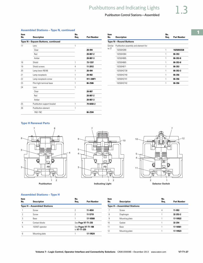
Assembled Stations—Type N, continued
Type H Renewal Parts
Assembled Stations—Type H
ItemNo. Description
No.Req. Part Number
Type N—Square Buttons, continued
17 Lens 1
Clear 28-494
Red 28-887-2
Amber 28-887-3
18 Shield 1 73-1337
19 Shield screws 4 11-2012
20 Lamp (neon NE48) 1 28-494
21 Lamp receptacle 1 28-902
22 Lamp receptacle screw 1 911-330F1
23 Pilot light terminal base 1 86-2586
24 Lens 1
Clear 28-887
Red 28-887-2
Amber 28-887-3
25 Pushbutton support bracket 1 79-6650-2
26 Pushbutton element 1
1NO-1NC 86-2594
ItemNo. Description
No.Req. Part Number
Type N—Round Buttons
Similar to 27
Pushbutton assembly and element for:
10250H289 1 10250H2538
10250H364 1 86-353
10250H685 1 86-353-8
10250H665 1 86-353-8
10250H671 1 86-353
10250H2738 1 86-353-3
10250H2740 1 86-356
10250H2741 1 86-356
10250H2742 1 86-356
1
Pushbutton Indicating Light
2
3
5
4
6
3
4
5
9
7 8
12
7
1 2 1
Selector Switch
2
11
1010
5
4
7
ItemNo. Description
No.Req. Part Number
Type H—Assembled Stations
1 Screw 2 11-4654
2 Screw 2 11-5719
3 Base 1 17-16560
4 Contact blocks See Page V7-T1-235
5 10250T operator See Pages V7-T1-188 to V7-T1-225
6 Mounting plate 1 17-19524
ItemNo. Description
No.Req. Part Number
Type H—Assembled Stations
7 Screw 4 11-953
8 Diaphragm 1 32-253-2
9 Mounting plate 1 17-19522
10 Gasket 1 32-254
11 Base 1 17-16561
12 Mounting plate 1 17-19523

V7-T1-28 Volume 7—Logic Control, Operator Interface and Connectivity Solutions CA08100008E—December 2013 www.eaton.com
1
1
1
1
1
1
1
1
1
1
1
1
1
1
1
1
1
1
1
1
1
1
1
1
1
1
1
1
1
1
1.3 Pushbuttons and Indicating Lights
Pushbutton Control Stations—Assembled
Technical Data and SpecificationsRatings
Maximum Ampere Ratings for Type N Control Stations
Maximum Ampere Ratings for Type H Control Stations
DimensionsApproximate Dimensions in Inches (mm)
Type N Control Stations
Special Purpose Control Stations
Note1 2.38 (60.5) for neon indicating light.
Volts AC Volts DCDescription 110 220 440 550 120 240 600
Make and emergency interrupt capacity 30 15 7.5 6 1.0 0.5 0.1
Normal load break 3 1.5 0.75 0.6 1.0 0.5 0.1
Continuous current 10 10 10 10 10 10 10
Description
Volts AC 50/60 Hz Volts DC
120 240 480 600 125 250
Make and emergency interrupt capacity 60 30 15 12 1.1 0.55
Normal load break 6 3 1.5 1.2 1.1 0.55
Continuous amperes 10 10 10 10 10 10
Voltamperes —
Make and emergency interrupt capacity 7200 7200 7200 7200 138 138
Normal load break 720 720 720 720 138 138
3.25(82.6)
4.00(101.6)
2.25 (57.2)
a1.50(38.1)
2.25(57.2)
3.25(82.6)
4.00(101.6)
2.25 (57.2)
a1.50(38.1)
2.25(57.2)
Single Button Station
5.00(127.0)
6.00(152.4)
2.25 (57.2)
a1.50(38.1)
2.25(57.2)
Two Button Station Three Button Station
3.13(79.5)
0.75 (19.1)Pipe Tap2.25
(57.2)
3.38(85.9)
6.25(158.8)
5.50(139.7)
Ship Wt.2.5 Lb (1.1 kg)

Volume 7—Logic Control, Operator Interface and Connectivity Solutions CA08100008E—December 2013 www.eaton.com V7-T1-29
1
1
1
1
1
1
1
1
1
1
1
1
1
1
1
1
1
1
1
1
1
1
1
1
1
1
1
1
1
1
1.3Pushbuttons and Indicating Lights
Pushbutton Control Stations—Assembled
Approximate Dimensions in Inches (mm)
Type H Control Stations
NEMA Type 3, 3R, 3S, 4, 4X, 13
10250T and E34
Approximate Enclosure Dimensions
Note1 No conduit entrance holes provided. Drill as required.
No. ofElements
DimensionsWide High Deep
1 and 2 4.50 (114.3) 8.25 (209.6) 4.50 (114.3)
3 4.50 (114.3) 10.75 (273.1) 4.25 (108.0)
NumberofElements
Surface Mounting
ConduitEntrance
Dimensions in In (mm)
WideA
HighB
DeepC
MountingD E
Cast
1 3.88(98.6)
4.0(101.6)
3.0(76.3)
2.69(68.3)
3.25(82.6)
3/4
2 3.88(98.6)
5.88(149.4)
3.0(76.3)
2.69(68.3)
5.13(130.3)
3/4
3 3.88(98.6)
7.75(196.9)
3.0(76.3)
2.69(68.3)
7.0(177.8)
1
4 33.88(98.6)
9.63(244.6)
3.0(76.3)
2.69(68.3)
8.88(225.6)
1
Polyester
1 3.81(96.8)
6.63(168.4)
3.38(85.9)
2.94(74.7)
4.88(124.0)
1
2 3.81(96.8)
6.63(168.4)
3.38(85.9)
2.94(74.7)
4.88(124.0)
1
3 3.81(96.8)
8.88(225.6)
3.38(85.9)
2.94(74.7)
7.13(181.1)
1
4 3.81(96.8)
6.63(168.4)
3.38(85.9)
2.94(74.7)
4.88(124.0)
1
Stainless Steel
1 3.00(76.2)
3.50(88.9)
3.00(76.2)
1.50(38.1)
4.25 (108.0)
1
2 3.50(88.9)
6.75(171.5)
3.00(76.2)
1.50(38.1)
7.50(190.5)
1
3 3.50(88.9)
9.00(228.6)
3.00(76.2)
1.50(38.1)
9.00(228.6)
1
4 3.50(88.9)
11.25(285.8)
3.00(76.2)
1.50(38.1)
12.00(304.8)
1
ASurface
D C
BE
4 Mtg. Holes — 10-32 Screw Size for 1 – 4 Element Die Cast/
Stainless Steel Enclosure7/32 Screw Size for
Polyester

V7-T1-30 Volume 7—Logic Control, Operator Interface and Connectivity Solutions CA08100008E—December 2013 www.eaton.com
1
1
1
1
1
1
1
1
1
1
1
1
1
1
1
1
1
1
1
1
1
1
1
1
1
1
1
1
1
1
1.4 Pushbuttons and Indicating Lights
16.2 mm Pushbuttons—RMQ-16
16.2 mm Pushbuttons—RMQ-16 ContentsDescription Page
16.2 mm Pushbuttons—RMQ-16Product Selection Guide . . . . . . . . . . . . . . . . . V7-T1-31
Pushbuttons—Non-Illuminated and Illuminated . . . . . . . . . . . . . . . . . . . . . . . . . . . V7-T1-32
Indicating Lights . . . . . . . . . . . . . . . . . . . . . . . . V7-T1-34
Emergency Stops . . . . . . . . . . . . . . . . . . . . . . . V7-T1-35
Selector Switches—Non-Illuminated, Illuminated and Keyed . . . . . . . . . . . . . . . . . . V7-T1-36
Accessories . . . . . . . . . . . . . . . . . . . . . . . . . . . V7-T1-40
Technical Data and Specifications . . . . . . . . . . V7-T1-43
Dimensions . . . . . . . . . . . . . . . . . . . . . . . . . . . V7-T1-45
Product OverviewProduct DescriptionThe RMQ-16 pushbutton line offers a wide array of functional and attractively designed illuminated and non-illuminated pushbuttons, selector switches, emergency stops and indicating lights. The illuminated line is offered with either incandescent or LED. RMQ-16 devices are designed with two front-of-panel operator sizes. The 18 x 18 mm or 25 x 25 mm square operators can help the user achieve over three times the information density compared with 22 mm ranges.
Features● Wide product breadth:
RMQ-16 offers illuminated and non-illuminated pushbuttons, keyed, non-keyed, and illuminated selector switches, emergency stops, and a large variety of accessories
● Custom laser etching: Hundreds of standard markings available in addition to infinite possible custom images with laser etching
● High durability: Pushbuttons and selector switches rated for 3 million mechanical operations
● High information density: Square operators (18 mm or 25 mm) allow for side-by-side mounting and achieve over three times the information density of typical 22 mm installations
● Laser etched operators● Heavy-duty construction
with IP65 on front of panel operators
● LED or incandescent illumination available
● Front-of-panel operators available in either 18 x 18 mm or 25 x 25 mm sizes
● Safety rated emergency stops (IEC 60947-5, positively driven contacts)
● Mounting diameter 16.2 mm to EN 50007
Standards and Certifications● UL Listed● CSA Certified● IEC/EN 60947-5 VDE-0660● IP65

Volume 7—Logic Control, Operator Interface and Connectivity Solutions CA08100008E—December 2013 www.eaton.com V7-T1-31
1
1
1
1
1
1
1
1
1
1
1
1
1
1
1
1
1
1
1
1
1
1
1
1
1
1
1
1
1
1
1.4Pushbuttons and Indicating Lights
16.2 mm Pushbuttons—RMQ-16
Product Selection GuidePushbuttons
Indicating Lights
Emergency Stops
Selector Switches
Description Non-Illuminated Illuminated
Product Selection Page V7-T1-32 Page V7-T1-33
Description Flush Extended
Product Selection Page V7-T1-34 Page V7-T1-34
Description Non-Illuminated Illuminated
Product Selection Page V7-T1-35 Page V7-T1-35
Description Non-Illuminated Illuminated Keyed
Product Selection Page V7-T1-36 Page V7-T1-37 Page V7-T1-38

V7-T1-32 Volume 7—Logic Control, Operator Interface and Connectivity Solutions CA08100008E—December 2013 www.eaton.com
1
1
1
1
1
1
1
1
1
1
1
1
1
1
1
1
1
1
1
1
1
1
1
1
1
1
1
1
1
1
1.4 Pushbuttons and Indicating Lights
16.2 mm Pushbuttons—RMQ-16
Pushbuttons—Non-Illuminated and IlluminatedCatalog Number SelectionCatalog Number Selection is for illustrative purposes only and not to be used to create new catalog numbers.
Pushbuttons—Non-Illuminated and Illuminated
Product Selection
Non-Illuminated Pushbuttons● Momentary or maintained● Customizable laser etched pushbutton operators● 18 mm or 25 mm square operator ● 3 million mechanical operations● IEC/EN 60947-5● IP65
Non-Illuminated Pushbuttons
Note1 To order separate button plates, see Page V7-T1-42.
TypeButton Color
Catalog Number18 x 18 mm 25 x 25 mm
Momentary Green Q18-D-GN Q25-D-GN
Red Q18-D-RT Q25-D-RT
Black Q18-D-SW Q25-D-SW
White Q18-D-WS Q25-D-WS
Blue Q18-D-BL Q25-D-BL
Yellow Q18-D-GE Q25-D-GE
Without Q18-D-X 1 Q25-D-X 1
Maintained Green Q18-DR-GN Q25-DR-GN
Red Q18-DR-RT Q25-DR-RT
Black Q18-DR-SW Q25-DR-SW
White Q18-DR-WS Q25-DR-WS
Blue Q18-DR-BL Q25-DR-BL
Yellow Q18-DR-GE Q25-DR-GE
Without Q18-DR-X 1 Q25-DR-X 1
Face Plate18 = 18 x 18 mm25 = 25 x 25 mm
Q 18 – DR – BL / WB
Button PlateGN = GreenRT = Red
SW = BlackWS = White
BL = BlueGE = Yellow
X = Without
Operator TypeD = Non-illuminated momentary
DR = Non-illuminated maintainedLT = Illuminated momentary
LTR = Illuminated maintained
BulbWB = With incandescent bulb 24V
Q18-D-GN

Volume 7—Logic Control, Operator Interface and Connectivity Solutions CA08100008E—December 2013 www.eaton.com V7-T1-33
1
1
1
1
1
1
1
1
1
1
1
1
1
1
1
1
1
1
1
1
1
1
1
1
1
1
1
1
1
1
1.4Pushbuttons and Indicating Lights
16.2 mm Pushbuttons—RMQ-16
Illuminated Pushbuttons● Momentary or maintained● LED or incandescent ● 18 mm or 25 mm square operator ● 3 million mechanical operations● IEC/EN 60947-5● IP65
Illuminated Pushbuttons Without Bulb 1
Notes1 To order with incandescent 24V bulb, insert a /WB at the end of the catalog number. Example, Q18-LT-GN/WB. 2 For a complete selection of incandescent 24V bulbs and LEDs, see Page V7-T1-40.
TypeButton Color
Catalog Number 2
18 x 18 mm 25 x 25 mm
Momentary Green Q18-LT-GN Q25-LT-GN
Red Q18-LT-RT Q25-LT-RT
Black Q18-LT-SW Q25-LT-SW
White Q18-LT-WS Q25-LT-WS
Blue Q18-LT-BL Q25-LT-BL
Yellow Q18-LT-GE Q25-LT-GE
Maintained Green Q18-LTR-GN Q25-LTR-GN
Red Q18-LTR-RT Q25-LTR-RT
Black Q18-LTR-SW Q25-LTR-SW
White Q18-LTR-WS Q25-LTR-WS
Blue Q18-LTR-BL Q25-LTR-BL
Yellow Q18-LTR-GE Q25-LTR-GE
Q18-LT-GE

V7-T1-34 Volume 7—Logic Control, Operator Interface and Connectivity Solutions CA08100008E—December 2013 www.eaton.com
1
1
1
1
1
1
1
1
1
1
1
1
1
1
1
1
1
1
1
1
1
1
1
1
1
1
1
1
1
1
1.4 Pushbuttons and Indicating Lights
16.2 mm Pushbuttons—RMQ-16
Indicating LightsCatalog Number SelectionCatalog Number Selection is for illustrative purposes only and not to be used to create new catalog numbers.
Indicating Lights—Flush and Extended
Product SelectionIndicating Lights● LED or incandescent ● Flush and extended lenses ● 18 mm or 25 mm square operator ● 3 million mechanical operations● IEC/EN 60947-5● IP65
Indicating Lights Without Bulb 1
Notes1 To order with incandescent 24V bulb, insert a /WB at the end of the catalog number. Example, Q18-LF-GN/WB. 2 For a complete selection of incandescent 24V bulbs and LEDs, see Page V7-T1-40.
Face Plate18 = 18 x 18 mm25 = 25 x 25 mm
Q 18 – LF – WS / WB
Button PlateGN = GreenRT = Red
WS = White
BL = BlueGE = Yellow
BezelLF = Flush indicator lightLH = Extended indicator light
BulbWB = With incandescent bulb 24V
TypeButton Color
Catalog Number 2
18 x 18 mm 25 x 25 mm
Flush Green Q18-LF-GN Q25-LF-GN
Red Q18-LF-RT Q25-LF-RT
White Q18-LF-WS Q25-LF-WS
Blue Q18-LF-BL Q25-LF-BL
Yellow Q18-LF-GE Q25-LF-GE
Extended. Green Q18-LH-GN Q25-LH-GN
Red Q18-LH-RT Q25-LH-RT
White Q18-LH-WS Q25-LH-WS
Blue Q18-LH-BL Q25-LH-BL
Yellow Q18-LH-GE Q25-LH-GE
Q18-LF-GE
Q18-LH-BL

Volume 7—Logic Control, Operator Interface and Connectivity Solutions CA08100008E—December 2013 www.eaton.com V7-T1-35
1
1
1
1
1
1
1
1
1
1
1
1
1
1
1
1
1
1
1
1
1
1
1
1
1
1
1
1
1
1
1.4Pushbuttons and Indicating Lights
16.2 mm Pushbuttons—RMQ-16
Emergency StopsCatalog Number SelectionCatalog Number Selection is for illustrative purposes only and not to be used to create new catalog numbers.
Emergency Stops—Non-Illuminated and Illuminated
Product Selection
Emergency Stops● Push/pull operation● Illuminated or non-illuminated● Emergency stop (red) or Machine stop (black) available● Suitable for use in safety applications● IEC/EN 60947-5● IP65
Emergency Stops—Non-Illuminated Emergency Stops—Illuminated 1
Note1 Includes built-in multiple LED 24 Vdc.
Face Plate25 = 25 x 25 mm
Q 25 – LPV – S
Operator TypePV = Emergency stop
LPV = Emergency stop (illuminated)
ColorBlank = Red
S = Black
Button Color
Catalog Number 25 x 25 mm
Red Q25PV
Black Q25PV-S
Q25PV
Button Color
Catalog Number 25 x 25 mm
Red Q25LPV
Black Q25LPV-S
Q25LPV

V7-T1-36 Volume 7—Logic Control, Operator Interface and Connectivity Solutions CA08100008E—December 2013 www.eaton.com
1
1
1
1
1
1
1
1
1
1
1
1
1
1
1
1
1
1
1
1
1
1
1
1
1
1
1
1
1
1
1.4 Pushbuttons and Indicating Lights
16.2 mm Pushbuttons—RMQ-16
Selector Switches—Non-Illuminated, Illuminated and KeyedCatalog Number SelectionCatalog Number Selection is for illustrative purposes only and not to be used to create new catalog numbers.
Selector Switches—Non-Illuminated
Product Selection
Non-Illuminated Selector Switches● Momentary or maintained● 18 mm or 25 mm square operator ● VS Anti-rotation feature● 3 million mechanical operations● IP65
Selector Switches—Non-Illuminated
Function PositionSwitchPosition
Catalog Number 18 x 18 mm 25 x 25 mm
Momentary 2 Q18WK1 Q25WK1
Maintained Q18WK1R Q25WK1R
Momentary 3 Q18WK3 Q25WK3
Maintained Q18WK3R Q25WK3R
Maintained/momentary Q18WK3R1 Q25WK3R1
Momentary/maintained Q18WK3R2 Q25WK3R2
Face Plate18 = 18 x 18 mm25 = 25 x 25 mm
Q 18 – WK1R
Selector PositionsWK1 = Two positions momentaryWK3 = Three positions momentary
WK1R = Two positions maintainedWK3R = Three positions maintained
WK3R1 = Three positions maintained/momentaryWK3R2 = Three positions momentary/maintained
Q18WK1

Volume 7—Logic Control, Operator Interface and Connectivity Solutions CA08100008E—December 2013 www.eaton.com V7-T1-37
1
1
1
1
1
1
1
1
1
1
1
1
1
1
1
1
1
1
1
1
1
1
1
1
1
1
1
1
1
1
1.4Pushbuttons and Indicating Lights
16.2 mm Pushbuttons—RMQ-16
Catalog Number SelectionCatalog Number Selection is for illustrative purposes only and not to be used to create new catalog numbers.
Selector Switches—Illuminated
Product Selection
Illuminated Selector Switches● LED or incandescent ● Momentary or maintained● 18 mm or 25 mm square operator ● VS Anti-rotation feature● 3 million mechanical operations● IP65
Selector Switches—Illuminated without Bulb 1
Notes1 To order with incandescent 24V bulb, insert a /WB at the end of the catalog number. Example, Q18LWK1-GN/WB. 2 For a complete selection of incandescent 24V bulbs and LEDs, see Page V7-T1-40.
Function PositionButtonColor
Switch Position
Catalog Number 2
18 x 18 mm 25 x 25 mm
Momentary 2 Green Q18LWK1-GN Q25LWK1-GN
Red Q18LWK1-RT Q25LWK1-RT
White Q18LWK1-WS Q25LWK1-WS
Maintained Green Q18LWK1R-GN Q25LWK1R-GN
Red Q18LWK1R-RT Q25LWK1R-RT
White Q18LWK1R-WS Q25LWK1R-WS
Momentary 3 Green Q18LWK3-GN Q25LWK3-GN
Red Q18LWK3-RT Q25LWK3-RT
White Q18LWK3-WS Q25LWK3-WS
Maintained Green Q18LWK3R-GN Q25LWK3R-GN
Red Q18LWK3R-RT Q25LWK3R-RT
White Q18LWK3R-WS Q25LWK3R-WS
Maintained/momentary
Green Q18LWK3R1-GN Q25LWK3R1-GN
Red Q18LWK3R1-RT Q25LWK3R1-RT
White Q18LWK3R1-WS Q25LWK3R1-WS
Momentary/maintained
Green Q18LWK3R2-GN Q25LWK3R2-GN
Red Q18LWK3R2-RT Q25LWK3R2-RT
White Q18LWK3R2-WS Q25LWK3R2-WS
Face Plate18 = 18 x 18 mm25 = 25 x 25 mm
Q 18 – LWK1 – WS / WB
Button PlateGN = GreenRT = Red
WS = White
BulbWB = With incandescent bulb 24VSwitch Positions
LWK1 = Two positions momentaryLWK3 = Three positions momentary
LWK1R = Two positions maintainedLWK3R = Three positions maintained
LWK3R1 = Three positions maintained/momentaryLWK3R2 = Three positions momentary/maintained
Q18LWK1-GN

V7-T1-38 Volume 7—Logic Control, Operator Interface and Connectivity Solutions CA08100008E—December 2013 www.eaton.com
1
1
1
1
1
1
1
1
1
1
1
1
1
1
1
1
1
1
1
1
1
1
1
1
1
1
1
1
1
1
1.4 Pushbuttons and Indicating Lights
16.2 mm Pushbuttons—RMQ-16
Catalog Number SelectionCatalog Number Selection is for illustrative purposes only and not to be used to create new catalog numbers.
Keyed Selector Switches—Two- and Three-Position
Product Selection
Keyed Selector Switches● 5 color options ● Momentary or maintained● 18 mm or 25 mm square operator ● VS Anti-rotation feature● 3 million mechanical operations● IP65
Keyed Selector Switches—Two-Position
Keyed Selector Switches—Three-Position
Note1 I = Key is removed at the left.
O = Key is removed at the center.II = Key is removed at the right.
FunctionButtonColor
SwitchPosition
Key RemovalPosition 1
Catalog Number18 x 18 mm 25 x 25 mm
Momentary Black O Q18S1 Q25S1
Maintained Black O Q18S1R Q25S1R
Maintained Black O Q18S1R-A1 Q25S1R-A1
FunctionButtonColor
SwitchPosition
Key RemovalPosition 1
Catalog Number18 x 18 mm 25 x 25 mm
Momentary Black O Q18S3 Q25S3
Maintained O, II Q18S3R Q25S3R
Maintained O Q18S3R-A1 Q25S3R-A1
I, O Q18S3R-A2 Q25S3R-A2
O, II Q18S3R-A3 Q25S3R-A3
Maintained/momentary
I, O Q18S3R-A4 Q25S3R-A4
O Q18S3R-A5 Q25S3R-A5
Momentary/maintained
O, II Q18S3R-A6 Q25S3R-A6
O Q18S3R-A7 Q25S3R-A7
Face Plate18 = 18 x 18 mm25 = 25 x 25 mm
Q 18 – S1 – A1 – WS
ColorGN = GreenRT = Red
SW = Black
WS = WhiteBL = Blue
Switch PositionsS1 = Two positions momentary S1R = Two positions maintained S3 = Three positions momentary S3R = Three positions maintained
Key CodeA1–A7 = Switch and key removal
positions (detailed below)
Q18S1

Volume 7—Logic Control, Operator Interface and Connectivity Solutions CA08100008E—December 2013 www.eaton.com V7-T1-39
1
1
1
1
1
1
1
1
1
1
1
1
1
1
1
1
1
1
1
1
1
1
1
1
1
1
1
1
1
1
1.4Pushbuttons and Indicating Lights
16.2 mm Pushbuttons—RMQ-16
Keyed Selector Switches, Multicolor—Two-Position
Keyed Selector Switches, Multicolor—Three-Position
Note1 I = Key is removed at the left.
O = Key is removed at the center.II = Key is removed at the right.
FunctionButtonColor
SwitchPosition
Key RemovalPosition 1
Catalog Number18 x 18 mm 25 x 25 mm
Momentary Green 0 Q18S1-GN Q25S1-GN
Red Q18S1-RT Q25S1-RT
White Q18S1-WS Q25S1-WS
Blue Q18S1-BL Q25S1-BL
Maintained Green 0 Q18S1R-GN Q25S1R-GN
Red Q18S1R-RT Q25S1R-RT
White Q18S1R-WS Q25S1R-WS
Blue Q18S1R-BL Q25S1R-BL
FunctionButtonColor
SwitchPosition
Key RemovalPosition 1
Catalog Number18 x 18 mm 25 x 25 mm
Momentary Green 0 Q18S3-GN Q25S3-GN
Red Q18S3-RT Q25S3-RT
White Q18S3-WS Q25S3-WS
Blue Q18S3-BL Q25S3-BL
Maintained Green 0, II Q18S3R-GN Q25S3R-GN
Red Q18S3R-RT Q25S3R-RT
White Q18S3R-WS Q25S3R-WS
Blue Q18S3R-BL Q25S3R-BL
Q18S1-BL
Q18S3-RT

V7-T1-40 Volume 7—Logic Control, Operator Interface and Connectivity Solutions CA08100008E—December 2013 www.eaton.com
1
1
1
1
1
1
1
1
1
1
1
1
1
1
1
1
1
1
1
1
1
1
1
1
1
1
1
1
1
1
1.4 Pushbuttons and Indicating Lights
16.2 mm Pushbuttons—RMQ-16
Accessories
Contact Elements
Screw Adapter
Incandescent 24V Bulbs
LEDs (AC/DC)
Insulated Ferrule
Combination Box Spanner
Anti-Rotation Tab
Housing
Blanking Plug
Cover Plate
Note1 Positive pole to X1. Integral suppressor circuit up to 1000V.
FeatureCatalogNumber
Normally open (N/O) E10
Normally closed (N/C) E01
FeatureCatalogNumber
Normally open (N/O) SRA10
Normally closed (N/C) SRA01
Lamp sockets SRAL
Voltage Current ColorCatalogNumber
6V 1W White WBGL6
12V WBGL12
24–28V WBGL24
Voltage Current ColorCatalogNumber
Multiple Chip LED
6V 45 mA Green WBLED-GN6
12V 24 mA WBLED-GN12
6V 45 mA Red WBLED-RT6
12V 24 mA WBLED-RT12
6V 45 mA Yellow WBGLED-GE6
12V 24 mA WBGLED-GE12
Single Chip LED 1
18–30V 7–12.5mA Green LEDWB-G
Red LEDWB-R
White LEDWB-W
Blue LEDWB-B
Yellow LEDWB-Y
E10
E01
SRA10
WBGL6
WBLED-GN6
DescriptionCatalogNumber
Insulated ferrule ISH2,8
DescriptionCatalogNumber
Mounting ring tool 16-MS
DescriptionCatalogNumber
Guard ring VS
Description ColorCatalogNumber
Surface mount enclosure White I8
Flush mount panel White E8
Black E8-SW
SizeCatalogNumber
18 x 18 mm Q18BS
25 x 25 mm Q25BS
Size ColorCatalogNumber
25 x 38 mm Black Q25AS
Gray Q25AGR
ISH2,8
R16-MS
VS
E8-SW
Q18BS
Q25AGR

Volume 7—Logic Control, Operator Interface and Connectivity Solutions CA08100008E—December 2013 www.eaton.com V7-T1-41
1
1
1
1
1
1
1
1
1
1
1
1
1
1
1
1
1
1
1
1
1
1
1
1
1
1
1
1
1
1
1.4Pushbuttons and Indicating Lights
16.2 mm Pushbuttons—RMQ-16
Insert Plate
Legend Plate
Legend Plate—Complete
Emergency Stop Labels
Extra Keys
Codes for Extra Keys
SizeCatalogNumber
10 x 22 mm BLANK 02SQ25
Size ColorCatalogNumber
25 x 38 mm Black Q25TS-X
Gray Q25TGR-X
Size EtchingCatalogNumber
25 x 38 START Q25TS-111
STOP Q25TS-110
FAULT Q25TS-250
HAND 0 AUTO Q25TS-197
MAN 0 AUTO Q25TS-397
0 Q25TS-10
I Q25TS-11
0 I Q25TS-90
I 0 II Q25TS-93
02SQ25
Q25TS-X
Q25TS_
Type FeatureCatalogNumber
Square 4 Languages SQT11
Blank SQT-GE
Circle 4 Languages SRT11
Blank SRT-GE
Color Catalog Number
Green ES16-GN
Red ES16-RT
Black ES16
White ES16-WS
Blue ES16-BL
SQT11
SRT11
ES16

V7-T1-42 Volume 7—Logic Control, Operator Interface and Connectivity Solutions CA08100008E—December 2013 www.eaton.com
1
1
1
1
1
1
1
1
1
1
1
1
1
1
1
1
1
1
1
1
1
1
1
1
1
1
1
1
1
1
1.4 Pushbuttons and Indicating Lights
16.2 mm Pushbuttons—RMQ-16
Button Plates
Instructions for Ordering Laser Inscriptions
1. Identify part number to be inscribed.
2. Pick symbol from library and identify suffix code associated with the symbol.
3. Order part number already listed in the catalog with -ETCH suffix.
4. When placing an order by fax or Vistaline on the web, reference order item number and indicate appropriate symbol code or desired text.
ExampleTo order a 25 mm green flush button plate with the inscription AUTO HAND:
Order Catalog Number 03TQ25-ETCH.AUTO HAND inscription is found on Page V7-T1-133 in the M22 Symbols Library, suffix code is X91.In the order notes, reference item number and suffix X91.
Note: For a complete list of available symbols, see Pages V7-T1-130 to V7-T1-136, M22 Symbols Library.
Type Color EtchingCatalogNumber Type Color Etching
CatalogNumber
18 x 18 mm Black — 01TQ18 25 x 25 mm Black — 01TQ25
CUSTOM 01TQ18-ETCH CUSTOM 01TQ25-ETCH
21TQ18 21TQ25
19TQ18 19TQ25
White — 02TQ18 “STOP” 112TQ25
CUSTOM 02TQ18-ETCH “ON” 221TQ25
20TQ18 White — 02TQ25
Green — 03TQ18 CUSTOM 02TQ25-ETCH
CUSTOM 03TQ18-ETCH 20TQ25
11TQ18 Green — 03TQ25
Red — 04TQ18 CUSTOM 03TQ25-ETCH
CUSTOM 04TQ18-ETCH “START” 111TQ25
10TQ18 11TQ25
Yellow — 05TQ18 Red — 04TQ25
CUSTOM 05TQ18-ETCH CUSTOM 04TQ25-ETCH
Blue — 06TQ18 “STOP” 110TQ25
CUSTOM 06TQ18-ETCH 10TQ25
“OFF” 217TQ25
Yellow — 05TQ25
CUSTOM 05TQ25-ETCH
Blue — 06TQ25
CUSTOM 06TQ25-ETCH
Button Plates

Volume 7—Logic Control, Operator Interface and Connectivity Solutions CA08100008E—December 2013 www.eaton.com V7-T1-43
1
1
1
1
1
1
1
1
1
1
1
1
1
1
1
1
1
1
1
1
1
1
1
1
1
1
1
1
1
1
1.4Pushbuttons and Indicating Lights
16.2 mm Pushbuttons—RMQ-16
Technical Data and Specifications RMQ-16
Specification Illuminated Pushbutton Operators (Maintained)
Illuminated Selector SwitchesDescription Unit Contact Elements Indicating Lights
General Technical Data
Standards UL, CSA, IEC/EN 60 947, VDE 0660, CE
Lifespan, mechanical (operations) x 105 100 30 (3) 3 —
Maximum operating frequency Ops/h 3600 3600 (1800) 1800 —
Operating force N 3 4 — —
Operating torque Nm — 0.2 —
Degree of protection to IEC/EN 60 529 IP20 with ISH2,8 IP65 IP65 IP65
Climatic proofing Damp heat, constant, to IEC 60 068-2-3/Damp heat, cyclical, to IEC 60 068-2-30
Ambient temperatureOpen °C –25 to 60 –25 to 60 –25 to 60 –25 to 60
Enclosed °C –25 to 40 –25 to 40 –25 to 40 –25 to 40
Mounting position As required As required As required As required
Mechanical shock resistance to IEC 60 068-2-27 (half-sinusoidal shock, duration 11 ms)
g 40 40 40 40
Terminal capacity (min./max.) mm2 0.5/1.0 0.5/1.0 0.5/1.0 0.5/1.0
Blade terminal 2.8 mm x 0.8 mm to DIN 46 244
Ferrule 2.8 mm x 0.8 mm to DIN 46 247 and IEC 60 760
Dimensions See Page V7-T1-45 See Page V7-T1-45 See Page V7-T1-45 See Page V7-T1-45
Contacts
Rated impulse withstand voltage U imp V 4000 800 800 800
Rated insulation voltage U i V 250 250 250 250
Overvoltage category/pollution degree III/3 III/3 III/3 III/3
Rated operational voltage Ue (max.) V 250 24 24 24
Rated operational current Ie (max.) A 4 — — —
Control circuit reliability at24 Vdc/5 mA (Fault probability Hr) <10–7, <1 fault in 107 operations
5 Vdc/1 mA (Fault probability Hr) <5 x 10⁻⁶, < fault in 5 x 10⁶ operations
Use of insulated ferrule ISH 2.8From Ue >24 Vac/dc recommended >24 Vac/dc recommended >24 Vac/dc recommended >24 Vac/dc recommended
From Ue >50 Vac or 120 Vdc is mandatory, even on unused blade terminals
Maximum short-circuit protective deviceFuseless Type FAZ-B6 — — —
Fuse A gG/gL 10 — — —
Switching Capacity
Rated operational current Ie AC-15 24V A 4 — — —
48V A 4 — — —
110V A 4 — — —
230V A 4 — — —
DC-13 24V A 3 — — —
42V A 1.0 — — —
60V A 0.8 — — —
110V A 0.5 — — —
220V A 0.2 — — —
UL/CSA Data UL listed File No. E 29 184, Guide No. NKCR/CSA certified File No. 46 552 Class No. 321103
Blade terminal 0.110 x 0.032 in 0.110 x 0.032 in 0.110 x 0.032 in 0.110 x 0.032 in
Fast-on connector 0.110 x 0.032 in AMP #60 197-1, 62 050-1 or equivalent
Rated voltage maximum AC Vac 300 24 24 24
Contact rating code AC E10/E01 C300/Q300 — — —
Thermal continuous test current A 2.5 — — —
Rated voltage maximum DC Vdc 300 — — —
Contact rating code DC E10/E01 C300/R300 — — —
Thermal continuous test current A 2.5 — — —

V7-T1-44 Volume 7—Logic Control, Operator Interface and Connectivity Solutions CA08100008E—December 2013 www.eaton.com
1
1
1
1
1
1
1
1
1
1
1
1
1
1
1
1
1
1
1
1
1
1
1
1
1
1
1
1
1
1
1.4 Pushbuttons and Indicating Lights
16.2 mm Pushbuttons—RMQ-16
RMQ-16, continued
Lifespan, Electrical AC-15 to IEC/EN 60 947-5-1 at 230V
Note1 See illuminated selector switches on Page V7-T1-37 for contact values.
Specification Emergency Stop Operators(Illuminated) 1Description Unit
Pushbutton Operators (Maintained) Selector Switches
Key-Released Operators
Emergency Stop Operators
General Technical Data
Standards UL, CSA, IEC/EN 60 947, VDE 0660, CE
Lifespan, mechanical (operations) x 105 30 (3) 3 3 0.5 0.5
Maximum operating frequency Ops/h 3600 (1800) 1800 1800 600 600
Operating force N 4 — — 25 25
Operating torque Nm — 0.2 0.4 — —
Degree of protection to IEC/EN 60 529 IP65 IP65 IP65 IP65 IP65
Climatic proofing Damp heat, constant, to IEC 60 068-2-3Damp heat, cyclical, to IEC 60 068-2-30
Ambient temperatureOpen °C –25 to 60 –25 to 60 –25 to 60 –25 to 60 –25 to 60
Enclosed °C –25 to 40 –25 to 40 –25 to 40 –25 to 40 –25 to 40
Mounting position As required As required As required As required As required
Mechanical shock resistance to IEC 60 068-2-27 (half-sinusoidal shock, duration 11 ms)
g 40 40 40 40 40
Terminal capacity (min./max.) mm2 — — — — 0.5/1.0
Blade terminal — — — — 2.8 x 0.8 mm
Ferrule — — — — 2.8 x 0.8 mm
Dimensions See Page V7-T1-45 See Page V7-T1-45 See Page V7-T1-45 See Page V7-T1-45 See Page V7-T1-45
0.1
E10
E01
0.2 0.3 0.4 0.5
0.6 0.8 1.0
3.00.7 4.02.00.9
l [A]e
0.1
0.2
0.3
0.4
0.5
0.6
0.8
1.0
2.0
3.0
4.0
5.0
0.7
0.9
x 106Operations
l = Rated operational current e

Volume 7—Logic Control, Operator Interface and Connectivity Solutions CA08100008E—December 2013 www.eaton.com V7-T1-45
1
1
1
1
1
1
1
1
1
1
1
1
1
1
1
1
1
1
1
1
1
1
1
1
1
1
1
1
1
1
1.4Pushbuttons and Indicating Lights
16.2 mm Pushbuttons—RMQ-16
DimensionsApproximate Dimensions in mm [in]
Actuating and Indicator Elements
Square Style Q…BS
Q…D-_, Q…DR-_ Q…S_ Q…WK_
Q…LT-_, Q…LTR-_, Q…LF-_ Q…LH-_ Q…LWK_
Q25PV_, Q25LPV_
M16 x 118.0
[0.71]
39.0 [1.54] Ø25.0 [0.98] Ø18.0 [0.71]
24.0 [0.94]4.0 [0.16]
39.0 [1.54]
11.0 [0.43]39.0 [1.54]
17.0[0.67] 13.0 [0.51]
39.0 [1.54]
26.0 [1.02]
11.0[0.43]
49.0 [1.93]
16.0[0.63]
49.0 [1.93]
26.0[1.02]
49.0 [1.93]
28.0 [1.10]
Ø 25.0[0.98]
Ø 28.0[1.10]
37.0 [1.46]39.0 [1.54]
49.0 [1.93]

V7-T1-46 Volume 7—Logic Control, Operator Interface and Connectivity Solutions CA08100008E—December 2013 www.eaton.com
1
1
1
1
1
1
1
1
1
1
1
1
1
1
1
1
1
1
1
1
1
1
1
1
1
1
1
1
1
1
1.4 Pushbuttons and Indicating Lights
16.2 mm Pushbuttons—RMQ-16
Approximate Dimensions in mm [in]
Front Fixing
Q18, Q25, E89, SRA, VS, M16
Drilling Dimensions
Drilling
Grid Dimension to IEC/EN 60947
Q25
Minimum Grid Spacing Dimension
Q18
Mounting Distance
Mounting
RMQ Screw Adapter Anti-Rotation Feature RMQ-16 Label Mount
SRA_ VS Q25TS-_
Blanking Plates
Q25AS
58.0 [2.28]
49.0 [1.93]
ISH 2.8[0.11]
E01, E10
6.0[0.24]
18.0[0.71]
16.2 [0.64]+ 0.2
0
25.0[0.98]
25.0[0.98]
18.0[0.71]
18.0 [0.71]
22.0[0.87]
5.6 [0.22]
18.5 [0.73]
17.8[0.70]
14.9 [0.59]
17.8[0.70]
38.0[1.50]
25.0 [0.98]
12.0[0.47]
13.0[0.51]
25.0 [0.98]
13.0[0.51]
4.0[0.16]
12.0[0.47]
38.0[1.50]
Note1 Exposed conductive part (metal).

Volume 7—Logic Control, Operator Interface and Connectivity Solutions CA08100008E—December 2013 www.eaton.com V7-T1-47
1
1
1
1
1
1
1
1
1
1
1
1
1
1
1
1
1
1
1
1
1
1
1
1
1
1
1
1
1
1
1.5Pushbuttons and Indicating Lights
22.5 mm Modular Pushbuttons—M22
22.5 mm Modular Pushbuttons—M22 ContentsDescription Page
22.5 mm Modular Pushbuttons—M22Product Selection Guide . . . . . . . . . . . . . . . . . . V7-T1-48
Accessories . . . . . . . . . . . . . . . . . . . . . . . . . . . V7-T1-111
Coding Adapter Guide . . . . . . . . . . . . . . . . . . . V7-T1-118
Technical Data and Specifications . . . . . . . . . . V7-T1-119
Dimensions . . . . . . . . . . . . . . . . . . . . . . . . . . . V7-T1-123
Symbols Library. . . . . . . . . . . . . . . . . . . . . . . . . V7-T1-129
DrawingsOnline
Product DescriptionEaton’s M22 industrial heavy-duty pushbutton line offers a wide array of functional, attractive and ergonomically designed illuminated and non-illuminated pushbuttons, selector switches, push-pulls, alternate action and twist-to-release operators. The complete illuminated line is only offered in LED light units to ensure high-quality brightness and up to 100,000 hours of LED illumination. M22 operators are available with either a silver or black nylon colored or chrome metal bezel. The space-saving modular construction of the M22 line makes on-the-job assembly fast and simplifies the stocking of both components and complete devices.
NEWEaton has expanded M22 pilot devices with a metal bezel option. The new M22M pushbutton is an elegant chrome metal bezel that is attractive, durable and rugged for heavy-duty environments. M22M devices are configurable and complement components within the M22 line.
Highly Modular and Versatile Line● Field convertible functions
(pushbuttons and selector switches), maintained to momentary
● Customizable laser engraving capabilities
LED Indicators● 100,000 hours of life
in high-vibration environments
● Lenses specifically designed for LED illumination
Rugged Design● Most pushbutton operators
and contact blocks exceed 5 million mechanical operations
● All components have IP66 rating, and some carry IP67 and IP69K for washdown environment; see Page V7-T1-119 for further technical data
Innovative Technologies● ASi communicating
devices● Palm switches
Standards and CertificationsAll operators and components are IEC/EN 60947 VDE 0660.
All operators carry an IP66 rating with some rated for washdown environment with IP67 and IP69K.
All pushbuttons, emergency-stops, indicating lights, potentiometers and selector switches carry NEMA 4X, 13.
Marine classification societies: Bureau Veritas (BV), Germanischer Lloyd (GL), and Lloyd’s Register of Shipping (LR) approved.

V7-T1-48 Volume 7—Logic Control, Operator Interface and Connectivity Solutions CA08100008E—December 2013 www.eaton.com
1
1
1
1
1
1
1
1
1
1
1
1
1
1
1
1
1
1
1
1
1
1
1
1
1
1
1
1
1
1
1.5 Pushbuttons and Indicating Lights
22.5 mm Modular Pushbuttons—M22
Features● Field convertible
pushbuttons and mushroom operators from maintained to momentary status
● Field convertible selector switches from momentary to maintained operation and vice versa
● LED offering only for all illuminated operators
● Laser engraved pushbuttons, lenses and enclosures
● Heavy-duty construction with a minimum of IP66 and UL NEMA® type 4X / 13 on front of panel operators. Many operators even carry IP67 and IP69K, for the toughest applications
● Silver, black or chrome metal bezel now available
● Snap-lock contact blocks and light units for front or base mounting
● Notched hole mounting with anti-rotation tab and central nut mounting on each operator
● Over 5 million mechanical operations and 1.6 million electrical (reference specification sheet)
● Direct opening action normally closed contacts
● Unique and innovative offerings, such as four-way pushbuttons and USB/RJ45 bulkhead interfaces
● Screw or spring-cage terminals
Benefits● Modular construction
makes assembly fast and simplifies stocking of components and complete devices
● Field convertibility of operator status for pushbuttons and selector switches helps distributors and customers reduce inventory and increase functionality
● LED offering only for improved brightness quality and up to 100,000 hours of operation
● Plastic construction is corrosion resistant. Operators are designed for rugged environments, ideal for washdown applications (reference each operator’s IP ratings and IEC/EN 60529 for ingress protection definition)
● Anti-rotation tab saves installation time and prevents operator rotation
● High mechanical and electrical life allows for use in tough and challenging applications
● Laser inscription capabilities allow for high-quality, wear-resistant markings
● All normally closed (NC) contacts are direct opening action, i.e., NC contacts are physically forced open by direct linkage with the pushbutton operator in the unlikely event of contact weld
● Some M22 operators are capable of communication via ASi protocol
● M22 offers USB and RJ45 connections
Product Selection GuidePushbuttons
Indicating Lights
Description Non-illuminated, flush Non-illuminated, extended Illuminated, flush Illuminated, extended
Operator Momentary Maintained Momentary Maintained Momentary Maintained Momentary Maintained
Product SelectionPages V7-T1-53 to V7-T1-55
Pages V7-T1-56, V7-T1-57
Pages V7-T1-58, V7-T1-59
Pages V7-T1-60, V7-T1-61
Pages V7-T1-63 to V7-T1-65
Pages V7-T1-66, V7-T1-67
Pages V7-T1-68, V7-T1-69
Pages V7-T1-70, V7-T1-71
Description Flat Conical
Product SelectionPages V7-T1-72, V7-T1-73
Pages V7-T1-72, V7-T1-73

Volume 7—Logic Control, Operator Interface and Connectivity Solutions CA08100008E—December 2013 www.eaton.com V7-T1-49
1
1
1
1
1
1
1
1
1
1
1
1
1
1
1
1
1
1
1
1
1
1
1
1
1
1
1
1
1
1
1.5Pushbuttons and Indicating Lights
22.5 mm Modular Pushbuttons—M22
Emergency Stops
Selector Switches
Mushroom Head Pushbuttons
Double Pushbuttons
Description Non-illuminated Illuminated Key release Mechanical indication
Product Selection Page V7-T1-75 Page V7-T1-75 Page V7-T1-76 Page V7-T1-76
DescriptionNon-illuminated knob type
Non-illuminated rotary type
Illuminated Key-operated
Product SelectionPages V7-T1-80, V7-T1-81
Pages V7-T1-82, V7-T1-83
Pages V7-T1-85 to V7-T1-87
Pages V7-T1-88 to V7-T1-91
Description Non-illuminated Non-illuminated
Operator Momentary Maintained
Product SelectionPages V7-T1-94, V7-T1-95
Pages V7-T1-96, V7-T1-97
DescriptionExtended pushbuttons and center light
Flush top and center light, extended bottom
Flush pushbuttons and center light
Operator Momentary Momentary —
Product Selection Page V7-T1-99 Page V7-T1-100 Page V7-T1-100

V7-T1-50 Volume 7—Logic Control, Operator Interface and Connectivity Solutions CA08100008E—December 2013 www.eaton.com
1
1
1
1
1
1
1
1
1
1
1
1
1
1
1
1
1
1
1
1
1
1
1
1
1
1
1
1
1
1
1.5 Pushbuttons and Indicating Lights
22.5 mm Modular Pushbuttons—M22
Four-Way Pushbuttons
Joysticks
Potentiometers
Acoustic Devices
Through-the-Door Operators
Bulkhead Interfaces
ASi Adapter Modules
Palm Switches
Assembled Control Stations
Description Non-interlocked Interlocked
Operator Momentary Maintained
Product Selection Page V7-T1-103 Page V7-T1-103
Description Joysticks
Product Selection Page V7-T1-104
Description Potentiometers
Product Selection Page V7-T1-106
Description Acoustic devices
Product Selection Page V7-T1-106
Description Through-the-door operators
Product Selection Page V7-T1-107
Description Bulkhead interfaces
Product Selection Page V7-T1-107
Description ASi adapter modules
Product Selection Page V7-T1-108
Description Palm switches
Product Selection Page V7-T1-109
Description Assembled control stations
Product Selection Page V7-T1-16

Volume 7—Logic Control, Operator Interface and Connectivity Solutions CA08100008E—December 2013 www.eaton.com V7-T1-51
1
1
1
1
1
1
1
1
1
1
1
1
1
1
1
1
1
1
1
1
1
1
1
1
1
1
1
1
1
1
1.5Pushbuttons and Indicating Lights
22.5 mm Modular Pushbuttons—M22
Point-of-Purchase Units
Note1 All NC contact blocks are positively driven contact.
Color TypeContact Configuration 1 Catalog Number
Black Flush momentary NO/NC M22-D-S-K11-P
Red Extended momentary NO/NC M22-DH-R-K11-P
Green Flush momentary NO/NC M22-D-G-K11-P
Red Ext. illuminated (12–30V) momentary NO/NC M22-DLH-R-K11-R-P
Red Ext. illuminated (85–264V) momentary NO/NC M22-DLH-R-K11-230R-P
White Flush illuminated (12–30V) maintained NO/NC M22-DRL-W-K11-W-P
White Flush illuminated (85–264V) maintained NO/NC M22-DRL-W-K11-230W-P
Red Indicating light (12–30V) — M22-L-R-R-P
Green Indicating light (12–30V) — M22-L-G-G-P
Red Indicting light (85–264V) — M22-L-R-230R-P
Green Indicating light (85–264 Vac) — M22-L-G-230G-P
Red Twist-to-release E-stop 1NO/2NC M22-PVT-K12-P
Red Illuminated (12–30V) push-pull E-stop 1NO/2NC M22-PVL-K12-R-P
Red Illuminated (85–264V) push-pull E-stop 1NO/2NC M22-PVL-K12-230R-P
— Two-position maintained V selector switch NO/NC M22-WKV-K11-P
— Three-position momentary selector switch NO/NC M22-WK3-K22-P
M22-_
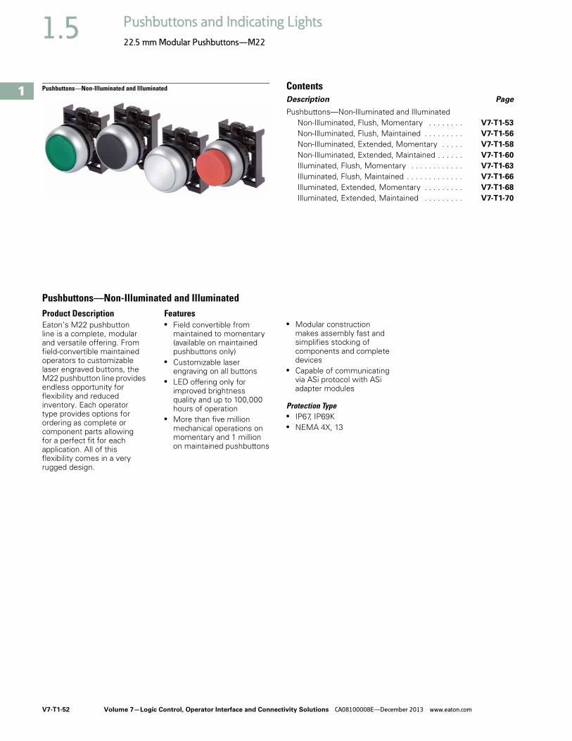
V7-T1-52 Volume 7—Logic Control, Operator Interface and Connectivity Solutions CA08100008E—December 2013 www.eaton.com
1
1
1
1
1
1
1
1
1
1
1
1
1
1
1
1
1
1
1
1
1
1
1
1
1
1
1
1
1
1
1.5 Pushbuttons and Indicating Lights
22.5 mm Modular Pushbuttons—M22
Pushbuttons—Non-Illuminated and Illuminated ContentsDescription Page
Pushbuttons—Non-Illuminated and IlluminatedNon-Illuminated, Flush, Momentary . . . . . . . . V7-T1-53
Non-Illuminated, Flush, Maintained . . . . . . . . . V7-T1-56
Non-Illuminated, Extended, Momentary . . . . . V7-T1-58
Non-Illuminated, Extended, Maintained . . . . . . V7-T1-60
Illuminated, Flush, Momentary . . . . . . . . . . . . V7-T1-63
Illuminated, Flush, Maintained . . . . . . . . . . . . . V7-T1-66
Illuminated, Extended, Momentary . . . . . . . . . V7-T1-68
Illuminated, Extended, Maintained . . . . . . . . . V7-T1-70
Pushbuttons—Non-Illuminated and IlluminatedProduct DescriptionEaton’s M22 pushbutton line is a complete, modular and versatile offering. From field-convertible maintained operators to customizable laser engraved buttons, the M22 pushbutton line provides endless opportunity for flexibility and reduced inventory. Each operator type provides options for ordering as complete or component parts allowing for a perfect fit for each application. All of this flexibility comes in a very rugged design.
Features● Field convertible from
maintained to momentary (available on maintained pushbuttons only)
● Customizable laser engraving on all buttons
● LED offering only for improved brightness quality and up to 100,000 hours of operation
● More than five million mechanical operations on momentary and 1 million on maintained pushbuttons
● Modular construction makes assembly fast and simplifies stocking of components and complete devices
● Capable of communicating via ASi protocol with ASi adapter modules
Protection Type● IP67, IP69K● NEMA 4X, 13

Volume 7—Logic Control, Operator Interface and Connectivity Solutions CA08100008E—December 2013 www.eaton.com V7-T1-53
1
1
1
1
1
1
1
1
1
1
1
1
1
1
1
1
1
1
1
1
1
1
1
1
1
1
1
1
1
1
1.5Pushbuttons and Indicating Lights
22.5 mm Modular Pushbuttons—M22
Catalog Number SelectionCatalog Number Selection is for illustrative purposes only and not to be used to create new catalog numbers.
Non-Illuminated Pushbuttons
Product SelectionNon-Illuminated Pushbuttons, Flush, Momentary
Complete Devices
Note1 All NC contact blocks are positively driven contact.
Button Color
Contact BlockConfiguration 1
Silver BezelCatalog Number
Black BezelCatalog Number
Metal BezelCatalog Number
Black NO M22-D-S-K10 M22S-D-S-K10 M22M-D-S-K10
NC M22-D-S-K01 M22S-D-S-K01 M22M-D-S-K01
2NO M22-D-S-K20 M22S-D-S-K20 M22M-D-S-K20
2NC M22-D-S-K02 M22S-D-S-K02 M22M-D-S-K02
1NO-1NC M22-D-S-K11 M22S-D-S-K11 M22M-D-S-K11
Red NO M22-D-R-K10 M22S-D-R-K10 M22M-D-R-K10
NC M22-D-R-K01 M22S-D-R-K01 M22M-D-R-K01
2NO M22-D-R-K20 M22S-D-R-K20 M22M-D-R-K20
2NC M22-D-R-K02 M22S-D-R-K02 M22M-D-R-K02
1NO-1NC M22-D-R-K11 M22S-D-R-K11 M22M-D-R-K11
Green NO M22-D-G-K10 M22S-D-G-K10 M22M-D-G-K10
NC M22-D-G-K01 M22S-D-G-K01 M22M-D-G-K01
2NO M22-D-G-K20 M22S-D-G-K20 M22M-D-G-K20
2NC M22-D-G-K02 M22S-D-G-K02 M22M-D-G-K02
1NO-1NC M22-D-G-K11 M22S-D-G-K11 M22M-D-G-K11
BezelM22 = SilverM22S = BlackM22M = Metal
M22 – D – S – X0 – K10
1 Silver bezel only.
Operator TypeD = Flush momentary
DH = Extended momentaryDG = Flush with guard 1DR = Flush maintained
DGH = Extended momentary with guard 1DRH = Extended maintained
Button Plate ColorG = GreenY = YellowB = Blue
S = BlackR = Red
W = White
InscriptionGB0 = STOPGB1 = STARTGB2 = CLOSEGB3 = UPGB4 = DOWNGB5 = OFFGB6 = ON
GB14 = RESETGB15 = FORWARDGB16 = REVERSE
X0 =X1 =X4 =X5 =X6 =X7 =X8 =
Contact BlocksK10 = 1NOK01 = 1NCK20 = 2NOK02 = 2NCK11 = 1NO-1NC
K30 = 3NOK03 = 3NCK21 = 2NO-1NCK12 = 1NO-2NC
M22-D-G-K10
M22S-D-G-K10
M22M-D-G-K10

V7-T1-54 Volume 7—Logic Control, Operator Interface and Connectivity Solutions CA08100008E—December 2013 www.eaton.com
1
1
1
1
1
1
1
1
1
1
1
1
1
1
1
1
1
1
1
1
1
1
1
1
1
1
1
1
1
1
1.5 Pushbuttons and Indicating Lights
22.5 mm Modular Pushbuttons—M22
Non-Illuminated Pushbuttons, Flush, Momentary
Operators Only 1
Silver Guarded
Notes1 Includes contact block mounting adapter. 2 Buttonless operator comes with three color buttons (black, red, green).3 Buttonless operator comes with all six color buttons (black, white, red, green, yellow, blue).
Button Color Inscription
Silver BezelCatalog Number
Black BezelCatalog Number
Metal BezelCatalog Number
Black — M22-D-S M22S-D-S M22M-D-S
Red — M22-D-R M22S-D-R M22M-D-R
STOP M22-D-R-GB0 M22S-D-R-GB0 —
M22-D-R-X0 M22S-D-R-X0 M22M-D-R-X0
Green — M22-D-G M22S-D-G M22M-D-G
START M22-D-G-GB1 M22S-D-G-GB1 M22M-D-G-GB1
M22-D-G-X1 M22S-D-G-X1 M22M-D-G-X1
White — M22-D-W M22S-D-W M22M-D-W
Blue — M22-D-B M22S-D-B M22M-D-B
Yellow — M22-D-Y M22S-D-Y M22M-D-Y
— — M22-D-X-SRG 2 M22S-D-X-SRG 2 M22M-D-X-SRG 2
— M22-D-X-SWRGYB 3 M22S-D-X-SWRGYB 3 M22M-D-X-SWRGYB 3
Button Color Inscription
Silver BezelCatalog Number
Black — M22-DG-S
Red — M22-DG-R
Green — M22-DG-G
White — M22-DG-W
Blue — M22-DG-B
Yellow — M22-DG-Y
— — M22-DG-X-SRG 2
— M22-DG-X-SWRGYB 3
M22-D-G
M22S-D-G
M22M-D-G
M22-DG-G

Volume 7—Logic Control, Operator Interface and Connectivity Solutions CA08100008E—December 2013 www.eaton.com V7-T1-55
1
1
1
1
1
1
1
1
1
1
1
1
1
1
1
1
1
1
1
1
1
1
1
1
1
1
1
1
1
1
1.5Pushbuttons and Indicating Lights
22.5 mm Modular Pushbuttons—M22
Non-Illuminated Pushbuttons, Flush, Momentary
ComponentsButton Plates 1 Buttonless Operator
Silver Guarded
Contact Blocks 1
Notes1 For complete listing of available button plates and contact blocks, see Accessories,
Pages V7-T1-111 to V7-T1-116. 2 Minimum order quantity of (10).3 When ordering, specify inscription per catalog number suffix from the Symbols
Library (see Pages V7-T1-129 to V7-T1-136) into the Order Notes. For example, M22-XD-S-ETCH; Order Notes: Mark with symbol X91, Line item #_.
4 Includes contact block mounting adapter. 5 All NC contact blocks are positively driven contact.
max. 5mmthickness
Note: Included with operator.
Color Inscription Catalog Number
Black — M22-XD-S 2
Custom M22-XD-S-ETCH 3
STOP M22-XD-S-GB0START M22-XD-S-GB1CLOSE M22-XD-S-GB2UP M22-XD-S-GB3DOWN M22-XD-S-GB4OFF M22-XD-S-GB5ON M22-XD-S-GB6TEST M22-XD-S-GB9FORWARD M22-XD-S-GB15REVERSE M22-XD-S-GB16RAISE M22-XD-S-GB17LOWER M22-XD-S-GB18
M22-XD-S-X0M22-XD-S-X1M22-XD-S-X2M22-XD-S-X4M22-XD-S-X5M22-XD-S-X7
Red — M22-XD-R 2
Custom M22-XD-R-ETCH 3
STOP M22-XD-R-GB0OFF M22-XD-R-GB5
M22-XD-R-X0Green — M22-XD-G 2
Custom M22-XD-G-ETCH 3
START M22-XD-G-GB1ON M22-XD-G-GB6
M22-XD-G-X1Blue — M22-XD-B 2
Custom M22-XD-B-ETCH 3
RESET M22-XD-B-GB14M22-XD-B-X6
White — M22-XD-W 2
Custom M22-XD-W-ETCH 3
START M22-XD-W-GB1M22-XD-W-X1
Yellow — M22-XD-Y 2
Custom M22-XD-Y-ETCH 3
Black, red, green — M22-XD-SRGBlack, white, red, green, yellow, blue
— M22-XD-SWRGYB
M22-XD-GSilver BezelCatalog Number 4
Black BezelCatalog Number 4
Metal BezelCatalog Number 4
M22-D-X M22S-D-X M22M-D-X
Silver BezelCatalog Number 4
M22-DG-X
TerminalType
Contact Configuration 5 Catalog Number
Screw NO M22-K10NO, early-make M22-K10PNC M22-K01NC, late-break M22-K01D
Spring-cage NO M22-CK10NC M22-CK01NC, late-break M22-CK01D2NO M22-CK202NC M22-CK02NO-NC M22-CK11
M22-D-X
M22S-D-X
M22M-D-X
M22-DG-X
M22-K10

V7-T1-56 Volume 7—Logic Control, Operator Interface and Connectivity Solutions CA08100008E—December 2013 www.eaton.com
1
1
1
1
1
1
1
1
1
1
1
1
1
1
1
1
1
1
1
1
1
1
1
1
1
1
1
1
1
1
1.5 Pushbuttons and Indicating Lights
22.5 mm Modular Pushbuttons—M22
Non-Illuminated Pushbuttons, Flush, Maintained 1
Operators Only 2
Notes1 Maintained pushbuttons can be converted in the field to momentary operation by switching the locking ring,
which is accessible through the side of the operator body.2 Includes contact block mounting adapter. 3 Buttonless operator comes with three color buttons (black, red, green).4 Buttonless operator comes with all six color buttons (black, white, red, green, yellow, blue).
Note: This pilot device features a selectable function switch that enables the device to be set to either maintained or momentary operation.
Button ColorSilver BezelCatalog Number
Black BezelCatalog Number
Metal BezelCatalog Number
Black M22-DR-S M22S-DR-S M22M-DR-S
Red M22-DR-R M22S-DR-R M22M-DR-R
Green M22-DR-G M22S-DR-G M22M-DR-G
White M22-DR-W M22S-DR-W M22M-DR-W
Blue M22-DR-B M22S-DR-B M22M-DR-B
Yellow M22-DR-Y M22S-DR-Y M22M-DR-Y3 M22-DR-X-SRG M22S-DR-X-SRG M22M-DR-X-SRG4 M22-DR-X-SWRGYB M22S-DR-X-SWRGYB M22M-DR-X-SWRGYB
M22-DR-S
M22S-DR-S
M22M-DR-S
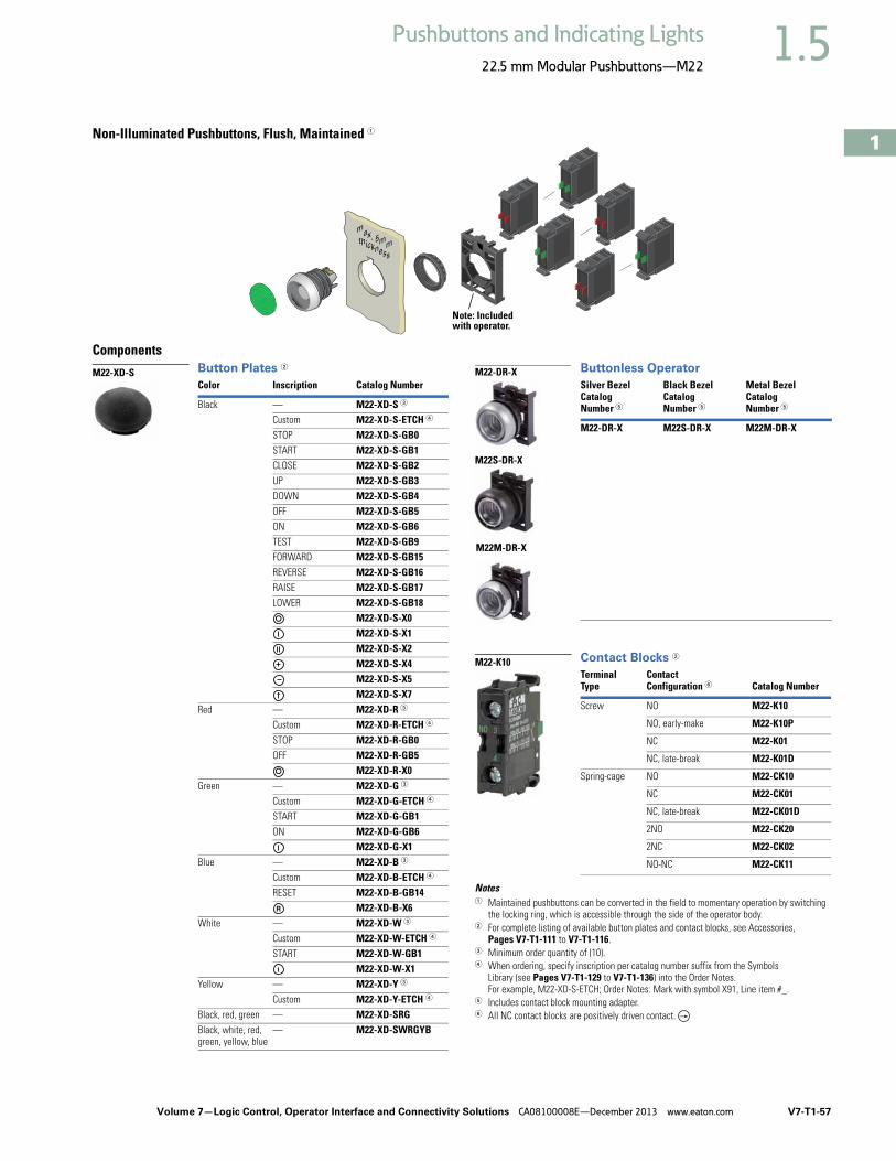
Volume 7—Logic Control, Operator Interface and Connectivity Solutions CA08100008E—December 2013 www.eaton.com V7-T1-57
1
1
1
1
1
1
1
1
1
1
1
1
1
1
1
1
1
1
1
1
1
1
1
1
1
1
1
1
1
1
1.5Pushbuttons and Indicating Lights
22.5 mm Modular Pushbuttons—M22
Non-Illuminated Pushbuttons, Flush, Maintained 1
ComponentsButton Plates 2 Buttonless Operator
Contact Blocks 2
Notes1 Maintained pushbuttons can be converted in the field to momentary operation by switching
the locking ring, which is accessible through the side of the operator body.2 For complete listing of available button plates and contact blocks, see Accessories,
Pages V7-T1-111 to V7-T1-116. 3 Minimum order quantity of (10).4 When ordering, specify inscription per catalog number suffix from the Symbols
Library (see Pages V7-T1-129 to V7-T1-136) into the Order Notes. For example, M22-XD-S-ETCH; Order Notes: Mark with symbol X91, Line item #_.
5 Includes contact block mounting adapter. 6 All NC contact blocks are positively driven contact.
max. 5mmthickness
Note: Included with operator.
Color Inscription Catalog Number
Black — M22-XD-S 3
Custom M22-XD-S-ETCH 4
STOP M22-XD-S-GB0START M22-XD-S-GB1CLOSE M22-XD-S-GB2UP M22-XD-S-GB3DOWN M22-XD-S-GB4OFF M22-XD-S-GB5ON M22-XD-S-GB6TEST M22-XD-S-GB9FORWARD M22-XD-S-GB15REVERSE M22-XD-S-GB16RAISE M22-XD-S-GB17LOWER M22-XD-S-GB18
M22-XD-S-X0M22-XD-S-X1M22-XD-S-X2M22-XD-S-X4M22-XD-S-X5M22-XD-S-X7
Red — M22-XD-R 3
Custom M22-XD-R-ETCH 4
STOP M22-XD-R-GB0OFF M22-XD-R-GB5
M22-XD-R-X0Green — M22-XD-G 3
Custom M22-XD-G-ETCH 4
START M22-XD-G-GB1ON M22-XD-G-GB6
M22-XD-G-X1Blue — M22-XD-B 3
Custom M22-XD-B-ETCH 4
RESET M22-XD-B-GB14M22-XD-B-X6
White — M22-XD-W 3
Custom M22-XD-W-ETCH 4
START M22-XD-W-GB1M22-XD-W-X1
Yellow — M22-XD-Y 3
Custom M22-XD-Y-ETCH 4
Black, red, green — M22-XD-SRGBlack, white, red, green, yellow, blue
— M22-XD-SWRGYB
M22-XD-SSilver BezelCatalog Number 5
Black BezelCatalog Number 5
Metal BezelCatalog Number 5
M22-DR-X M22S-DR-X M22M-DR-X
TerminalType
Contact Configuration 6 Catalog Number
Screw NO M22-K10
NO, early-make M22-K10P
NC M22-K01
NC, late-break M22-K01D
Spring-cage NO M22-CK10
NC M22-CK01
NC, late-break M22-CK01D
2NO M22-CK20
2NC M22-CK02
NO-NC M22-CK11
M22-DR-X
M22S-DR-X
M22M-DR-X
M22-K10

V7-T1-58 Volume 7—Logic Control, Operator Interface and Connectivity Solutions CA08100008E—December 2013 www.eaton.com
1
1
1
1
1
1
1
1
1
1
1
1
1
1
1
1
1
1
1
1
1
1
1
1
1
1
1
1
1
1
1.5 Pushbuttons and Indicating Lights
22.5 mm Modular Pushbuttons—M22
Non-Illuminated Pushbuttons, Extended, MomentaryComplete Devices
Silver Guarded
Operators Only 2
Silver Guarded
Notes1 All NC contact blocks are positively driven contact. 2 Includes contact block mounting adapter.3 Buttonless operator comes with three color buttons (black, red, green).4 Buttonless operator comes with all six color buttons (black, white, red, green, yellow, blue).
Button Color
Contact BlockConfiguration 1
Silver BezelCatalog Number
Black BezelCatalog Number
Metal BezelCatalog Number
Red NO M22-DH-R-K10 M22S-DH-R-K10 M22M-DH-R-K10
NC M22-DH-R-K01 M22S-DH-R-K01 M22M-DH-R-K01
2NO M22-DH-R-K20 M22S-DH-R-K20 M22M-DH-R-K20
2NC M22-DH-R-K02 M22S-DH-R-K02 M22M-DH-R-K02
1NO-1NC M22-DH-R-K11 M22S-DH-R-K11 M22M-DH-R-K11
Button Color
Contact BlockConfiguration 1
Silver BezelCatalog Number
Red NO M22-DGH-R-K10
NC M22-DGH-R-K01
2NO M22-DGH-R-K20
2NC M22-DGH-R-K02
1NO-1NC M22-DGH-R-K11
Button Color Inscription
Silver BezelCatalog Number
Black BezelCatalog Number
Metal BezelCatalog Number
Black — M22-DH-S M22S-DH-S M22M-DH-S
Red — M22-DH-R M22S-DH-R M22M-DH-R
STOP M22-DH-R-GB0 M22S-DH-R-GB0 M22M-DH-R-GB0
M22-DH-R-X0 M22S-DH-R-X0 M22M-DH-R-X0
Green — M22-DH-G M22S-DH-G M22M-DH-G
White — M22-DH-W M22S-DH-W M22M-DH-W
Blue — M22-DH-B M22S-DH-B M22M-DH-B
Yellow — M22-DH-Y M22S-DH-Y M22M-DH-Y3 — M22-DH-X-SRG M22S-DH-X-SRG M22M-DH-X-SRG 4 — M22-DH-X-SWRGYB M22S-DH-X-SWRGYB M22M-DH-X-SWRGYB
Button Color Inscription
Silver BezelCatalog Number
Black — M22-DGH-S
Red — M22-DGH-R
STOP M22-DGH-R-GB0
M22-DGH-R-X0
Green — M22-DGH-G
White — M22-DGH-W
Blue — M22-DGH-B
Yellow — M22-DGH-Y
M22-DH-R-K10
M22S-DH-R-K10
M22M-DH-R-K10
M22-DGH-R-K10
M22-DH-R
M22S-DH-R
M22M-DH-R
M22-DGH-R-K10

Volume 7—Logic Control, Operator Interface and Connectivity Solutions CA08100008E—December 2013 www.eaton.com V7-T1-59
1
1
1
1
1
1
1
1
1
1
1
1
1
1
1
1
1
1
1
1
1
1
1
1
1
1
1
1
1
1
1.5Pushbuttons and Indicating Lights
22.5 mm Modular Pushbuttons—M22
Non-Illuminated Pushbuttons, Extended, Momentary
ComponentsButton Plates 1 Buttonless Operator
Silver Guarded
Contact Blocks 1
Notes1 For complete listing of available button plates and contact blocks, see Accessories,
Pages V7-T1-111 to V7-T1-116.2 Minimum order quantity of (10).3 When ordering, specify inscription per catalog number suffix from the Symbols
Library (see Pages V7-T1-129 to V7-T1-136) into the Order Notes. For example, M22-XDH-S-ETCH; Order Notes: Mark with symbol X91, Line item #_.
4 Includes contact block mounting adapter. 5 All NC contact blocks are positively driven contact.
max. 5mmthickness
Note: Included with operator.
Color Inscription Catalog Number
Black — M22-XDH-S 2
Custom M22-XDH-S-ETCH 3
STOP M22-XDH-S-GB0START M22-XDH-S-GB1CLOSE M22-XDH-S-GB2UP M22-XDH-S-GB3DOWN M22-XDH-S-GB4OFF M22-XDH-S-GB5ON M22-XDH-S-GB6TEST M22-XDH-S-GB9FORWARD M22-XDH-S-GB15REVERSE M22-XDH-S-GB16RAISE M22-XDH-S-GB17LOWER M22-XDH-S-GB18
M22-XDH-S-X0M22-XDH-S-X1M22-XDH-S-X2M22-XDH-S-X4M22-XDH-S-X5M22-XDH-S-X7
Red — M22-XDH-R 2
Custom M22-XDH-R-ETCH 3
STOP M22-XDH-R-GB0OFF M22-XDH-R-GB5
M22-XDH-R-X0Green — M22-XDH-G 2
Custom M22-XDH-G-ETCH 3
START M22-XDH-G-GB1ON M22-XDH-G-GB6
M22-XDH-G-X1Blue — M22-XDH-B 2
Custom M22-XDH-B-ETCH 3
RESET M22-XDH-B-GB14M22-XDH-B-X6
White — M22-XDH-W 2
Custom M22-XDH-W-ETCH 3
START M22-XDH-W-GB1M22-XDH-W-X1
Yellow — M22-XDH-Y 2
Custom M22-XDH-Y-ETCH 3
Black, red, green — M22-XDH-SRGBlack, white, red, green, yellow, blue
— M22-XDH-SWRGYB
M22-XDH-RSilver BezelCatalog Number 4
Black BezelCatalog Number 4
Metal BezelCatalog Number 4
M22-D-X M22S-D-X M22M-D-X
Silver BezelCatalog Number 4
M22-DG-X
TerminalType
Contact Configuration 5 Catalog Number
Screw NO M22-K10NO, early-make M22-K10PNC M22-K01NC, late-break M22-K01D
Spring-cage NO M22-CK10NC M22-CK01NC, late-break M22-CK01D2NO M22-CK202NC M22-CK02NO-NC M22-CK11
M22-D-X
M22S-D-X
M22M-D-X
M22-DG-X
M22-K10

V7-T1-60 Volume 7—Logic Control, Operator Interface and Connectivity Solutions CA08100008E—December 2013 www.eaton.com
1
1
1
1
1
1
1
1
1
1
1
1
1
1
1
1
1
1
1
1
1
1
1
1
1
1
1
1
1
1
1.5 Pushbuttons and Indicating Lights
22.5 mm Modular Pushbuttons—M22
Non-Illuminated Pushbuttons, Extended, Maintained 1
Operators Only 2
Notes1 Maintained pushbuttons can be converted in the field to momentary operation by switching the locking ring,
which is accessible through the side of the operator body.2 Includes contact block mounting adapter.3 Buttonless operator comes with three color buttons (black, red, green).4 Buttonless operator comes with all six color buttons (black, white, red, green, yellow, blue).
Note: This pilot device features a selectable function switch that enables the device to be set to either maintained or momentary operation.
Button ColorSilver BezelCatalog Number
Black BezelCatalog Number
Metal BezelCatalog Number
Black M22-DRH-S M22S-DRH-S M22M-DRH-S
Red M22-DRH-R M22S-DRH-R M22M-DRH-R
Green M22-DRH-G M22S-DRH-G M22M-DRH-G
White M22-DRH-W M22S-DRH-W M22M-DRH-W
Blue M22-DRH-B M22S-DRH-B M22M-DRH-B
Yellow M22-DRH-Y M22S-DRH-Y M22M-DRH-Y3 M22-DRH-X-SRG M22S-DRH-X-SRG M22M-DRH-X-SRG4 M22-DRH-X-SWRGYB M22S-DRH-X-SWRGYB M22M-DRH-X-SWRGYB
M22-DRH-W
M22S-DRH-W
M22M-DRH-W

Volume 7—Logic Control, Operator Interface and Connectivity Solutions CA08100008E—December 2013 www.eaton.com V7-T1-61
1
1
1
1
1
1
1
1
1
1
1
1
1
1
1
1
1
1
1
1
1
1
1
1
1
1
1
1
1
1
1.5Pushbuttons and Indicating Lights
22.5 mm Modular Pushbuttons—M22
Non-Illuminated Pushbuttons, Extended, Maintained 1
ComponentsButton Plates 2 Buttonless Operator
Contact Blocks 2
Notes1 Maintained pushbuttons can be converted in the field to momentary operation by
switching the locking ring, which is accessible through the side of the operator body.2 For complete listing of available button plates and contact blocks, see Accessories,
Pages V7-T1-111 to V7-T1-116. 3 Minimum order quantity of (10).4 When ordering, specify inscription per catalog number suffix from the Symbols
Library (see Pages V7-T1-129 to V7-T1-136) into the Order Notes. For example, M22-XDH-S-ETCH; Order Notes: Mark with symbol X91, Line item #_.
5 Includes contact block mounting adapter. 6 All NC contact blocks are positively driven contact.
max. 5mmthickness
Note: Included with operator.
Color Inscription Catalog Number
Black — M22-XDH-S 3
Custom M22-XDH-S-ETCH 4
STOP M22-XDH-S-GB0START M22-XDH-S-GB1CLOSE M22-XDH-S-GB2UP M22-XDH-S-GB3DOWN M22-XDH-S-GB4OFF M22-XDH-S-GB5ON M22-XDH-S-GB6TEST M22-XDH-S-GB9FORWARD M22-XDH-S-GB15REVERSE M22-XDH-S-GB16RAISE M22-XDH-S-GB17LOWER M22-XDH-S-GB18
M22-XDH-S-X0M22-XDH-S-X1M22-XDH-S-X2M22-XDH-S-X4M22-XDH-S-X5M22-XDH-S-X7
Red — M22-XDH-R 3
Custom M22-XDH-R-ETCH 4
STOP M22-XDH-R-GB0OFF M22-XDH-R-GB5
M22-XDH-R-X0Green — M22-XDH-G 3
Custom M22-XDH-G-ETCH 4
START M22-XDH-G-GB1ON M22-XDH-G-GB6
M22-XDH-G-X1Blue — M22-XDH-B 3
Custom M22-XDH-B-ETCH 4
RESET M22-XDH-B-GB14M22-XDH-B-X6
White — M22-XDH-W 3
Custom M22-XDH-W-ETCH 4
START M22-XDH-W-GB1M22-XDH-W-X1
Yellow — M22-XDH-Y 3
Custom M22-XDH-Y-ETCH 4
Black, red, green — M22-XDH-SRGBlack, white, red, green, yellow, blue
— M22-XDH-SWRGYB
M22-XDH-WSilver BezelCatalog Number 5
Black BezelCatalog Number 5
Metal BezelCatalog Number 5
M22-DR-X M22S-DR-X M22M-DR-X
TerminalType
Contact Configuration 6 Catalog Number
Screw NO M22-K10NO, early-make M22-K10PNC M22-K01NC, late-break M22-K01D
Spring-cage NO M22-CK10NC M22-CK01NC, late-break M22-CK01D2NO M22-CK202NC M22-CK02NO-NC M22-CK11
M22-DR-X
M22S-DR-X
M22M-DR-X
M22-K10

V7-T1-62 Volume 7—Logic Control, Operator Interface and Connectivity Solutions CA08100008E—December 2013 www.eaton.com
1
1
1
1
1
1
1
1
1
1
1
1
1
1
1
1
1
1
1
1
1
1
1
1
1
1
1
1
1
1
1.5 Pushbuttons and Indicating Lights
22.5 mm Modular Pushbuttons—M22
Catalog Number SelectionCatalog Number Selection is for illustrative purposes only and not to be used to create new catalog numbers.
Illuminated Pushbuttons
BezelM22 = SilverM22S = BlackM22M = Metal
1 Silver bezel only.
Operator TypeDL = Illuminated flush momentary
DLH = Illuminated extended momentaryDGL = Illuminated flush momentary with guard 1DRL = Illuminated flush maintained
DGLH = Illuminated extended momentary with guard 1DRLH = Illuminated extended maintained
Light Units12–30 Vac/Vdc
W = WhiteR = RedG = GreenB = Blue
85–264 Vac230W = White230R = Red230G = Green230B = Blue
InscriptionGB0 = STOPGB1 = STARTGB2 = CLOSEGB3 = UPGB4 = DOWNGB5 = OFFGB6 = ON
GB14 = RESETGB15 = FORWARDGB16 = REVERSE
X0 =X1 =X4 =X5 =X6 =
Contact BlocksK10 = 1NOK01 = 1NCK20 = 2NOK02 = 2NCK11 = 1NO-1NC
K30 = 3NOK03 = 3NCK21 = 2NO-1NCK12 = 1NO-2NC
Lens ColorW = WhiteR = RedG = GreenY = YellowB = BlueA = Amber
M22 – DRL – R – GB0 – K10 – 230R

Volume 7—Logic Control, Operator Interface and Connectivity Solutions CA08100008E—December 2013 www.eaton.com V7-T1-63
1
1
1
1
1
1
1
1
1
1
1
1
1
1
1
1
1
1
1
1
1
1
1
1
1
1
1
1
1
1
1.5Pushbuttons and Indicating Lights
22.5 mm Modular Pushbuttons—M22
Product SelectionIlluminated Pushbuttons, Flush, Momentary
Complete Devices
Note1 All NC contact blocks are positively driven contact.
Button Color
Contact BlockConfiguration 1 Light Unit Voltage
Silver BezelCatalog Number
Black BezelCatalog Number
Metal BezelCatalog Number
Red NC 12–30 Vac/Vdc M22-DL-R-K01-R M22S-DL-R-K01-R M22M-DL-R-K01-R
NC 85–264 Vac M22-DL-R-K01-230R M22S-DL-R-K01-230R M22M-DL-R-K01-230R
2NC 12–30 Vac/Vdc M22-DL-R-K02-R M22S-DL-R-K02-R M22M-DL-R-K02-R
2NC 85–264 Vac M22-DL-R-K02-230R M22S-DL-R-K02-230R M22M-DL-R-K02-230R
1NO/1NC 12–30 Vac/Vdc M22-DL-R-K11-R M22S-DL-R-K11-R M22M-DL-R-K11-R
1NO/1NC 85–264 Vac M22-DL-R-K11-230R M22S-DL-R-K11-230R M22M-DL-R-K11-230R
Green NO 12–30 Vac/Vdc M22-DL-G-K10-G M22S-DL-G-K10-G M22M-DL-G-K10-G
NO 85–264 Vac M22-DL-G-K10-230G M22S-DL-G-K10-230G M22M-DL-G-K10-230G
2NO 12–30 Vac/Vdc M22-DL-G-K20-G M22S-DL-G-K20-G M22M-DL-G-K20-G
2NO 85–264 Vac M22-DL-G-K20-230G M22S-DL-G-K20-230G M22M-DL-G-K20-230G
1NO/1NC 12–30 Vac/Vdc M22-DL-G-K11-G M22S-DL-G-K11-G M22M-DL-G-K11-G
1NO/1NC 85–264 Vac M22-DL-G-K11-230G M22S-DL-G-K11-230G M22M-DL-G-K11-230G
White NO 12–30 Vac/Vdc M22-DL-W-K10-W M22S-DL-W-K10-W —
NO 85–264 Vac M22-DL-W-K10-230W M22S-DL-W-K10-230W M22M-DL-W-K10-230W
2NO 12–30 Vac/Vdc M22-DL-W-K20-W M22S-DL-W-K20-W —
2NO 85–264 Vac M22-DL-W-K20-230W M22S-DL-W-K20-230W M22M-DL-W-K20-230W
1NO/1NC 12–30 Vac/Vdc M22-DL-W-K11-W M22S-DL-W-K11-W —
1NO/1NC 85–264 Vac M22-DL-W-K11-230W M22S-DL-W-K11-230W M22M-DL-W-K11-230W
M22-DL-G-K01-G
M22S-DL-G-K01-G
M22M-DL-G-K01-G

V7-T1-64 Volume 7—Logic Control, Operator Interface and Connectivity Solutions CA08100008E—December 2013 www.eaton.com
1
1
1
1
1
1
1
1
1
1
1
1
1
1
1
1
1
1
1
1
1
1
1
1
1
1
1
1
1
1
1.5 Pushbuttons and Indicating Lights
22.5 mm Modular Pushbuttons—M22
Illuminated Pushbuttons, Flush, MomentaryOperators Only 1
Silver Guarded
Note1 Includes contact block mounting adapter.
Button ColorSilver BezelCatalog Number
Black BezelCatalog Number
Metal BezelCatalog Number
Red M22-DL-R M22S-DL-R M22M-DL-R
Green M22-DL-G M22S-DL-G M22M-DL-G
White M22-DL-W M22S-DL-W M22M-DL-W
Blue M22-DL-B M22S-DL-B M22M-DL-B
Yellow M22-DL-Y M22S-DL-Y M22M-DL-Y
Amber M22-DL-A M22S-DL-A M22M-DL-A
Button ColorSilver BezelCatalog Number
Red M22-DGL-R
Green M22-DGL-G
White M22-DGL-W
Blue M22-DGL-B
Yellow M22-DGL-Y
M22-DL-G
M22S-DL-G
M22M-DL-G
M22-DGL-G

Volume 7—Logic Control, Operator Interface and Connectivity Solutions CA08100008E—December 2013 www.eaton.com V7-T1-65
1
1
1
1
1
1
1
1
1
1
1
1
1
1
1
1
1
1
1
1
1
1
1
1
1
1
1
1
1
1
1.5Pushbuttons and Indicating Lights
22.5 mm Modular Pushbuttons—M22
Illuminated Pushbuttons, Flush, Momentary
ComponentsButton Lenses 1
Buttonless Operator
Silver Guarded
Light Units 1
Contact Blocks 1
Notes1 For complete listing of available button lenses, light units and contact blocks, see
Accessories, Pages V7-T1-111 to V7-T1-116. 2 Minimum order quantity of (10).3 When ordering, specify inscription per catalog number suffix from the Symbols
Library (see Pages V7-T1-129 to V7-T1-136) into the Order Notes. For example, M22-XDL-R-ETCH; Order Notes: Mark with symbol X91, Line item #_.
4 Includes contact block mounting adapter. 5 All NC contact blocks are positively driven contact.
max. 5mmthickness
Note: Included with operator.
Color Inscription Catalog Number
Red — M22-XDL-R 2
Custom M22-XDL-R-ETCH 3
STOP M22-XDL-R-GB0OFF M22-XDL-R-GB5
M22-XDL-R-X0Green — M22-XDL-G 2
Custom M22-XDL-G-ETCH 3
START M22-XDL-G-GB1ON M22-XDL-G-GB6
M22-XDL-G-X1Blue — M22-XDL-B 2
Custom M22-XDL-B-ETCH 3
RESET M22-XDL-B-GB14M22-XDL-B-X6
White — M22-XDL-W 2
Custom M22-XDL-W-ETCH 3
Yellow — M22-XDL-Y 2
Custom M22-XDL-Y-ETCH 3
Amber — M22-XDL-A Custom M22-XDL-A-ETCH
Silver BezelCatalog Number 4
Black BezelCatalog Number 4
Metal BezelCatalog Number 4
M22-DL-X M22S-DL-X M22M-DL-X
Silver BezelCatalog Number 4
M22-DGL-X
M22-XDL-G
M22-DL-X
M22S-DL-X
M22M-DL-X
M22-DGL-X
TerminalType
LED Color
Light UnitVoltage Catalog Number
Screw White 12–30Vac/Vdc
M22-LED-WRed M22-LED-RGreen M22-LED-GBlue M22-LED-B
Screw White 85–264Vac
M22-LED230-WRed M22-LED230-RGreen M22-LED230-GBlue M22-LED230-B
TerminalType
Contact Configuration 5 Catalog Number
Screw NO M22-K10NO, early-make M22-K10PNC M22-K01NC, late-break M22-K01D
Spring-cage NO M22-CK10NC M22-CK01NC, late-break M22-CK01D2NO M22-CK202NC M22-CK02NO-NC M22-CK11
M22-LED-W
M22-K10

V7-T1-66 Volume 7—Logic Control, Operator Interface and Connectivity Solutions CA08100008E—December 2013 www.eaton.com
1
1
1
1
1
1
1
1
1
1
1
1
1
1
1
1
1
1
1
1
1
1
1
1
1
1
1
1
1
1
1.5 Pushbuttons and Indicating Lights
22.5 mm Modular Pushbuttons—M22
Illuminated Pushbuttons, Flush, Maintained 2
Complete Devices
Operators Only 3
Notes1 All NC contact blocks are positively driven contact. 2 Maintained pushbuttons can be converted in the field to momentary operation by switching the locking ring,
which is accessible through the side of the operator body.3 Includes contact block mounting adapter.
Note: This pilot device features a selectable function switch that enables the device to be set to either maintained or momentary operation.
Button Color
Contact BlockConfiguration 1 Light Unit Voltage
Silver BezelCatalog Number
Black BezelCatalog Number
Metal BezelCatalog Number
White NO 12–30 Vac/Vdc M22-DRL-W-K10-W M22S-DRL-W-K10-W M22M-DRL-W-K10-W
NO 85–264 Vac M22-DRL-W-K10-230W M22S-DRL-W-K10-230W M22M-DRL-W-K10-230W
NC 12–30 Vac/Vdc M22-DRL-W-K01-W M22S-DRL-W-K01-W M22M-DRL-W-K01-W
NC 85–264 Vac M22-DRL-W-K01-230W M22S-DRL-W-K01-230W M22M-DRL-W-K01-230W
2NO 12–30 Vac/Vdc M22-DRL-W-K20-W M22S-DRL-W-K20-W M22M-DRL-W-K20-W
2NO 85–264 Vac M22-DRL-W-K20-230W M22S-DRL-W-K20-230W M22M-DRL-W-K20-230W
2NC 12–30 Vac/Vdc M22-DRL-W-K02-W M22S-DRL-W-K02-W M22M-DRL-W-K02-W
2NC 85–264 Vac M22-DRL-W-K02-230W M22S-DRL-W-K02-230W M22M-DRL-W-K02-230W
1NO/1NC 12–30 Vac/Vdc M22-DRL-W-K11-W M22S-DRL-W-K11-W M22M-DRL-W-K11-W
1NO/1NC 85–264 Vac M22-DRL-W-K11-230W M22S-DRL-W-K11-230W M22M-DRL-W-K11-230W
Button ColorSilver BezelCatalog Number
Black BezelCatalog Number
Metal BezelCatalog Number
Red M22-DRL-R M22S-DRL-R M22M-DRL-R
Green M22-DRL-G M22S-DRL-G M22M-DRL-G
White M22-DRL-W M22S-DRL-W M22M-DRL-W
Blue M22-DRL-B M22S-DRL-B M22M-DRL-B
Yellow M22-DRL-Y M22S-DRL-Y M22M-DRL-Y
Amber M22-DRL-A M22S-DRL-A M22M-DRL-A
M22-DRL-W-K10-W
M22S-DRL-W-K10-W
M22M-DRL-W-K10-W
M22-DRL-W
M22S-DRL-W
M22M-DRL-W

Volume 7—Logic Control, Operator Interface and Connectivity Solutions CA08100008E—December 2013 www.eaton.com V7-T1-67
1
1
1
1
1
1
1
1
1
1
1
1
1
1
1
1
1
1
1
1
1
1
1
1
1
1
1
1
1
1
1.5Pushbuttons and Indicating Lights
22.5 mm Modular Pushbuttons—M22
Illuminated Pushbuttons, Flush, Maintained 1
ComponentsButton Lenses 2
Buttonless Operator
Light Units 2
Contact Blocks 2
Notes1 Maintained pushbuttons can be converted in the field to momentary operation by
switching the locking ring, which is accessible through the side of the operator body.2 For complete listing of available button lenses, light units and contact blocks, see
Accessories, Pages V7-T1-111 to V7-T1-116. 3 Minimum order quantity of (10).4 When ordering, specify inscription per catalog number suffix from the Symbols
Library (see Pages V7-T1-129 to V7-T1-136) into the Order Notes. For example, M22-XDL-R-ETCH; Order Notes: Mark with symbol X91, Line item #_.
5 Includes contact block mounting adapter. 6 All NC contact blocks are positively driven contact.
max. 5mmthickness
Note: Included with operator.
Color Inscription Catalog Number
Red — M22-XDL-R 3
Custom M22-XDL-R-ETCH 4
STOP M22-XDL-R-GB0OFF M22-XDL-R-GB5
M22-XDL-R-X0Green — M22-XDL-G 3
Custom M22-XDL-G-ETCH 4
START M22-XDL-G-GB1ON M22-XDL-G-GB6
M22-XDL-G-X1Blue — M22-XDL-B 3
Custom M22-XDL-B-ETCH 4
RESET M22-XDL-B-GB14M22-XDL-B-X6
White — M22-XDL-W 3
Custom M22-XDL-W-ETCH 4
Yellow — M22-XDL-Y 3
Custom M22-XDL-Y-ETCH 4
Amber — M22-XDL-A Custom M22-XDL-A-ETCH
Silver BezelCatalog Number 5
Black BezelCatalog Number 5
Metal BezelCatalog Number 5
M22-DRL-X M22S-DRL-X M22M-DRL-X
M22-XDL-W
M22-DRL-X
M22S-DRL-X
M22M-DRL-X
TerminalType
LED Color
Light UnitVoltage Catalog Number
Screw White 12–30 Vac/Vdc
M22-LED-WRed M22-LED-RGreen M22-LED-GBlue M22-LED-B
Screw White 85–264 Vac
M22-LED230-WRed M22-LED230-RGreen M22-LED230-GBlue M22-LED230-B
TerminalType
Contact Configuration 6 Catalog Number
Screw NO M22-K10NO, early-make M22-K10PNC M22-K01NC, late-break M22-K01D
Spring-cage NO M22-CK10NC M22-CK01NC, late-break M22-CK01D2NO M22-CK202NC M22-CK02NO-NC M22-CK11
M22-LED-W
M22-K10

V7-T1-68 Volume 7—Logic Control, Operator Interface and Connectivity Solutions CA08100008E—December 2013 www.eaton.com
1
1
1
1
1
1
1
1
1
1
1
1
1
1
1
1
1
1
1
1
1
1
1
1
1
1
1
1
1
1
1.5 Pushbuttons and Indicating Lights
22.5 mm Modular Pushbuttons—M22
Illuminated Pushbuttons, Extended, Momentary
Complete Devices
Complete Press-to-Test Units
Operators Only 2
Silver Guarded
Notes1 All NC contact blocks are positively driven contact. 2 Includes contact block mounting adapter.
Button Color
Contact BlockConfiguration 1
Light Unit Voltage
Silver BezelCatalog Number
Black BezelCatalog Number
Metal BezelCatalog Number
Red 1NO/1NC 12–30 Vac/Vdc M22-DLH-R-K11-R M22S-DLH-R-K11-R M22M-DLH-R-K11-R
1NO/1NC 85–264 Vac M22-DLH-R-K11-230R M22S-DLH-R-K11-230R M22M-DLH-R-K11-230R
Green 2NO 12–30 Vac/Vdc M22-DLH-G-K20-G M22S-DLH-G-K20-G M22M-DLH-G-K20-G
2NO 85–264 Vac M22-DLH-G-K20-230G M22S-DLH-G-K20-230G M22M-DLH-G-K20-230G
White 2NO 12–30 Vac/Vdc M22-DLH-W-K20-W M22S-DLH-W-K20-W M22M-DLH-W-K20-W
2NO 85–264 Vac M22-DLH-W-K20-230W M22S-DLH-W-K20-230W M22M-DLH-W-K20-230W
Button Color Light Unit VoltageSilver BezelCatalog Number
Black BezelCatalog Number
Red 12–30 Vac/Vdc M22-T-R-R M22S-T-R-R
Blue M22-T-B-B M22S-T-B-B
Yellow M22-T-Y-W M22S-T-Y-W
Green M22-T-G-G M22S-T-G-G
White M22-T-W-W M22S-T-W-W
Red 85–264 Vac M22-T-R-230R M22S-T-R-230R
Blue M22-T-R-230B M22S-T-B-230B
Yellow M22-T-Y-230W M22S-T-Y-230W
Green M22-T-G-230G M22S-T-G-230G
White M22-T-W-230W M22S-T-W-230W
Button ColorSilver BezelCatalog Number
Black BezelCatalog Number
Metal BezelCatalog Number
Red M22-DLH-R M22S-DLH-R M22M-DLH-R
Green M22-DLH-G M22S-DLH-G M22M-DLH-G
White M22-DLH-W M22S-DLH-W M22M-DLH-W
Blue M22-DLH-B M22S-DLH-B M22M-DLH-B
Yellow M22-DLH-Y M22S-DLH-Y M22M-DLH-Y
Amber M22-DLH-A M22S-DLH-A M22M-DLH-A
Button ColorSilver BezelCatalog Number
Red M22-DGLH-R
Green M22-DGLH-G
White M22-DGLH-W
Blue M22-DGLH-B
Yellow M22-DGLH-Y
M22-DLH-R-K11-R
M22S-DLH-R-K11-R
M22-DLH-R
M22S-DLH-R
M22M-DLH-R
M22-DGLH-R

Volume 7—Logic Control, Operator Interface and Connectivity Solutions CA08100008E—December 2013 www.eaton.com V7-T1-69
1
1
1
1
1
1
1
1
1
1
1
1
1
1
1
1
1
1
1
1
1
1
1
1
1
1
1
1
1
1
1.5Pushbuttons and Indicating Lights
22.5 mm Modular Pushbuttons—M22
Illuminated Pushbuttons, Extended, Momentary
ComponentsButton Lenses 1
Buttonless Operator
Silver Guarded
Light Units 1
Contact Blocks 1
Notes1 For complete listing of available button lenses, light units and contact blocks, see
Accessories, Pages V7-T1-111 to V7-T1-116. 2 Minimum order quantity of (10).3 When ordering, specify inscription per catalog number suffix from the Symbols
Library (see Pages V7-T1-129 to V7-T1-136) into the Order Notes. For example, M22-XDH-S-ETCH; Order Notes: Mark with symbol X91, Line item #_.
4 Includes contact block mounting adapter. 5 All NC contact blocks are positively driven contact.
max. 5mmthickness
Note: Included with operator.
Color Inscription Catalog Number
Red — M22-XDLH-R 2
Custom M22-XDLH-R-ETCH 3
STOP M22-XDLH-R-GB0OFF M22-XDLH-R-GB5
M22-XDLH-R-X0Green — M22-XDLH-G 2
Custom M22-XDLH-G-ETCH 3
START M22-XDLH-G-GB1ON M22-XDLH-G-GB6
M22-XDLH-G-X1Blue — M22-XDLH-B 2
Custom M22-XDLH-B-ETCH 3
RESET M22-XDLH-B-GB14M22-XDLH-B-X6
White — M22-XDLH-W 2
Custom M22-XDLH-W-ETCH 3
Yellow — M22-XDLH-Y 2
Custom M22-XDLH-Y-ETCH 3
Amber — M22-XDLH-A Custom M22-XDLH-A-ETCH
Silver BezelCatalog Number 4
Black BezelCatalog Number 4
Metal BezelCatalog Number 4
M22-DL-X M22S-DL-X M22M-DL-X
Silver BezelCatalog Number 4
M22-DGL-X
M22-XDH-R
M22-DL-X
M22S-DL-X
M22M-DL-X
M22-DGL-X
TerminalType
LED Color
Light UnitVoltage Catalog Number
Screw White 12–30Vac/Vdc
M22-LED-WRed M22-LED-RGreen M22-LED-GBlue M22-LED-B
Screw White 85–264Vac
M22-LED230-WRed M22-LED230-RGreen M22-LED230-GBlue M22-LED230-B
TerminalType
Contact Configuration 5 Catalog Number
Screw NO M22-K10NO, early-make M22-K10PNC M22-K01NC, late-break M22-K01D
Spring-cage NO M22-CK10NC M22-CK01NC, late-break M22-CK01D2NO M22-CK202NC M22-CK02NO-NC M22-CK11
M22-LED-W
M22-K10

V7-T1-70 Volume 7—Logic Control, Operator Interface and Connectivity Solutions CA08100008E—December 2013 www.eaton.com
1
1
1
1
1
1
1
1
1
1
1
1
1
1
1
1
1
1
1
1
1
1
1
1
1
1
1
1
1
1
1.5 Pushbuttons and Indicating Lights
22.5 mm Modular Pushbuttons—M22
Illuminated Pushbuttons, Extended, Maintained 1
Operators Only 2
Notes1 Maintained pushbuttons can be converted in the field to momentary operation by switching the locking ring,
which is accessible through the side of the operator body.2 Includes contact block mounting adapter.
Note: This pilot device features a selectable function switch that enables the device to be set to either maintained or momentary operation.
Button ColorSilver BezelCatalog Number
Black BezelCatalog Number
Metal BezelCatalog Number
Red M22-DRLH-R M22S-DRLH-R M22M-DRLH-R
Green M22-DRLH-G M22S-DRLH-G M22M-DRLH-G
White M22-DRLH-W M22S-DRLH-W M22M-DRLH-W
Blue M22-DRLH-B M22S-DRLH-B M22M-DRLH-B
Yellow M22-DRLH-Y M22S-DRLH-Y M22M-DRLH-Y
Amber M22-DRLH-A M22S-DRLH-A M22M-DRLH-A
M22-DRLH-W
M22S-DRLH-W
M22M-DRLH-W
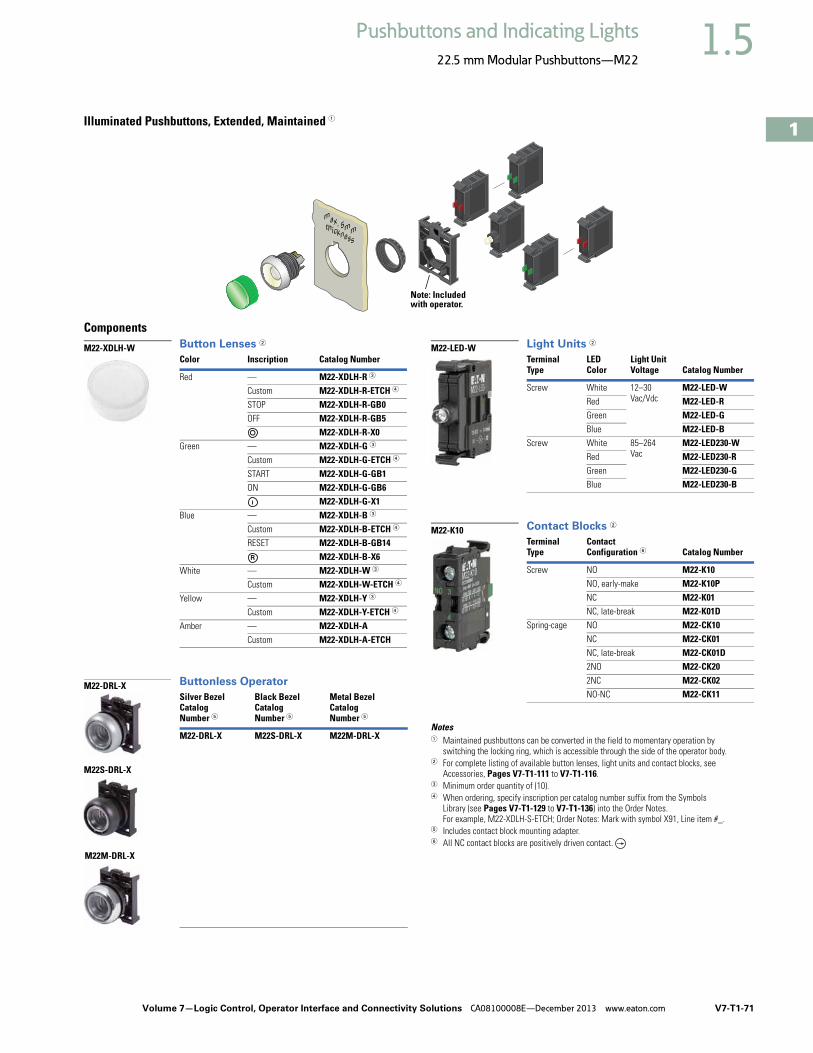
Volume 7—Logic Control, Operator Interface and Connectivity Solutions CA08100008E—December 2013 www.eaton.com V7-T1-71
1
1
1
1
1
1
1
1
1
1
1
1
1
1
1
1
1
1
1
1
1
1
1
1
1
1
1
1
1
1
1.5Pushbuttons and Indicating Lights
22.5 mm Modular Pushbuttons—M22
Illuminated Pushbuttons, Extended, Maintained 1
ComponentsButton Lenses 2
Buttonless Operator
Light Units 2
Contact Blocks 2
Notes1 Maintained pushbuttons can be converted in the field to momentary operation by
switching the locking ring, which is accessible through the side of the operator body.2 For complete listing of available button lenses, light units and contact blocks, see
Accessories, Pages V7-T1-111 to V7-T1-116. 3 Minimum order quantity of (10).4 When ordering, specify inscription per catalog number suffix from the Symbols
Library (see Pages V7-T1-129 to V7-T1-136) into the Order Notes. For example, M22-XDLH-S-ETCH; Order Notes: Mark with symbol X91, Line item #_.
5 Includes contact block mounting adapter. 6 All NC contact blocks are positively driven contact.
max. 5mmthickness
Note: Included with operator.
Color Inscription Catalog Number
Red — M22-XDLH-R 3
Custom M22-XDLH-R-ETCH 4
STOP M22-XDLH-R-GB0OFF M22-XDLH-R-GB5
M22-XDLH-R-X0Green — M22-XDLH-G 3
Custom M22-XDLH-G-ETCH 4
START M22-XDLH-G-GB1ON M22-XDLH-G-GB6
M22-XDLH-G-X1Blue — M22-XDLH-B 3
Custom M22-XDLH-B-ETCH 4
RESET M22-XDLH-B-GB14M22-XDLH-B-X6
White — M22-XDLH-W 3
Custom M22-XDLH-W-ETCH 4
Yellow — M22-XDLH-Y 3
Custom M22-XDLH-Y-ETCH 4
Amber — M22-XDLH-A Custom M22-XDLH-A-ETCH
Silver BezelCatalog Number 5
Black BezelCatalog Number 5
Metal BezelCatalog Number 5
M22-DRL-X M22S-DRL-X M22M-DRL-X
M22-XDLH-W
M22-DRL-X
M22S-DRL-X
M22M-DRL-X
TerminalType
LED Color
Light UnitVoltage Catalog Number
Screw White 12–30Vac/Vdc
M22-LED-WRed M22-LED-RGreen M22-LED-GBlue M22-LED-B
Screw White 85–264 Vac
M22-LED230-WRed M22-LED230-RGreen M22-LED230-GBlue M22-LED230-B
TerminalType
Contact Configuration 6 Catalog Number
Screw NO M22-K10NO, early-make M22-K10PNC M22-K01NC, late-break M22-K01D
Spring-cage NO M22-CK10NC M22-CK01NC, late-break M22-CK01D2NO M22-CK202NC M22-CK02NO-NC M22-CK11
M22-LED-W
M22-K10

V7-T1-72 Volume 7—Logic Control, Operator Interface and Connectivity Solutions CA08100008E—December 2013 www.eaton.com
1
1
1
1
1
1
1
1
1
1
1
1
1
1
1
1
1
1
1
1
1
1
1
1
1
1
1
1
1
1
1.5 Pushbuttons and Indicating Lights
22.5 mm Modular Pushbuttons—M22
Indicating LightsProduct DescriptionEaton’s M22 indicating lights use the combination of a durable, bright LED unit and modern lenses designed specifically for this type of LED to create a bright and visible indicating light.
As with the pushbuttons, the indicating light lenses can be laser engraved. Indicating lights can be ordered as complete devices, including lens and LED unit, or as modular components.
Features● Customizable laser
engraving on all lenses● LED offering only for
improved brightness quality and up to 100,000 hours of operation
● Lenses designed specifically for LED illumination
● Modular construction makes assembly fast and simplifies stocking of components and complete devices
● Capable of communicating via ASi protocol with ASi adapter modules
Protection Type● IP67, IP69K● NEMA 4X, 13
Catalog Number SelectionCatalog Number Selection is for illustrative purposes only and not to be used to create new catalog numbers.
Indicating Lights
Product SelectionIndicating Lights, Flush
Complete Devices
Operators Only 1
Note1 Includes contact block mounting adapter.
Lens Color Light Color Light Unit Voltage Catalog Number
White White 12–30 Vac/Vdc M22-L-W-WRed Red M22-L-R-RGreen Green M22-L-G-GYellow White M22-L-Y-WBlue Blue M22-L-B-BAmber White M22-L-A-WWhite White 85–264 Vac M22-L-W-230WRed Red M22-L-R-230RGreen Green M22-L-G-230GYellow White M22-L-Y-230WBlue Blue M22-L-B-230BAmber White M22-L-A-230W
Lens Color Catalog Number Lens Color Catalog Number
Flat Conical
White M22-L-W White M22-LH-WRed M22-L-R Red M22-LH-RGreen M22-L-G Green M22-LH-GYellow M22-L-Y Yellow M22-LH-YBlue M22-L-B Blue M22-LH-BAmber M22-L-A Amber M22-LH-A
Note: Light unit should match color of lens. Use white light unit with yellow lens.
Lens ColorW = WhiteR = RedG = GreenY = YellowB = Blue
M22 - L – B – GB8 – B
Operator TypeM22-L = Flush indicating light
1 When ordering, specify inscription per catalog number suffix from the Symbols Library (see Pages V7-T1-129 to V7-T1-136) into the Order Notes. For example, M22-L-B-ETCH; Order Notes: Mark with symbol X91, Line item #_.
Plate Inscription
ETCH = Custom 1GB5 = OFFGB6 = ONGB8 = FAULT
GB15 = FORWARDGB16 = REVERSE
Light Units12–30 Vac/Vdc
W = WhiteR = RedG = GreenB = Blue
85–264 Vac230W = White230R = Red230G = Green230B = Blue
M22-L-R-R
M22-L-R M22-LH-R

Volume 7—Logic Control, Operator Interface and Connectivity Solutions CA08100008E—December 2013 www.eaton.com V7-T1-73
1
1
1
1
1
1
1
1
1
1
1
1
1
1
1
1
1
1
1
1
1
1
1
1
1
1
1
1
1
1
1.5Pushbuttons and Indicating Lights
22.5 mm Modular Pushbuttons—M22
Indicating Lights, Flush
ComponentsLenses 1
Lensless Indicating Light
Light Units 14
Notes1 For complete listing of available lenses and light units, see Accessories,
Pages V7-T1-111 to V7-T1-116. 2 Minimum order quantity of (10).3 When ordering, specify inscription per catalog number suffix from the Symbols
Library (see Pages V7-T1-129 to V7-T1-136) into the Order Notes. For example, M22-XL-R-ETCH; Order Notes: Mark with symbol X91, Line item #_.
4 Select the same color LED element as lens color; for yellow and amber lenses, choose a white LED.
max. 5mmthickness
Note: Included with operator.
Color Inscription Catalog Number
Flat
Red — M22-XL-R 2
Custom M22-XL-R-ETCH 3
OFF M22-XL-R-GB5Green — M22-XL-G 2
Custom M22-XL-G-ETCH 3
ON M22-XL-G-GB6REVERSE M22-XL-G-GB16
Blue — M22-XL-B 2
Custom M22-XL-B-ETCH 3
FAULT M22-XL-B-GB8White — M22-XL-W 2
Custom M22-XL-W-ETCH 3
OFF M22-XL-W-GB5ON M22-XL-W-GB6FAULT M22-XL-W-GB8FORWARD M22-XL-W-GB15
Yellow — M22-XL-Y 2
Custom M22-XL-Y-ETCH 3
Amber — M22-XL-A 2
Custom M22-XL-A-ETCH 3
Conical
Red — M22-XLH-R Green — M22-XLH-G Blue — M22-XLH-B White — M22-XLH-W Yellow — M22-XLH-Y Amber — M22-XLH-A
Catalog Number
M22-L-X
M22-XL-R
M22-L-X
TerminalType
LED Color
Light UnitVoltage Catalog Number
Screw White 12–30 Vac/Vdc
M22-LED-WRed M22-LED-RGreen M22-LED-GBlue M22-LED-B
Screw White 85–264 Vac
M22-LED230-WRed M22-LED230-RGreen M22-LED230-GBlue M22-LED230-B
M22-LED-W
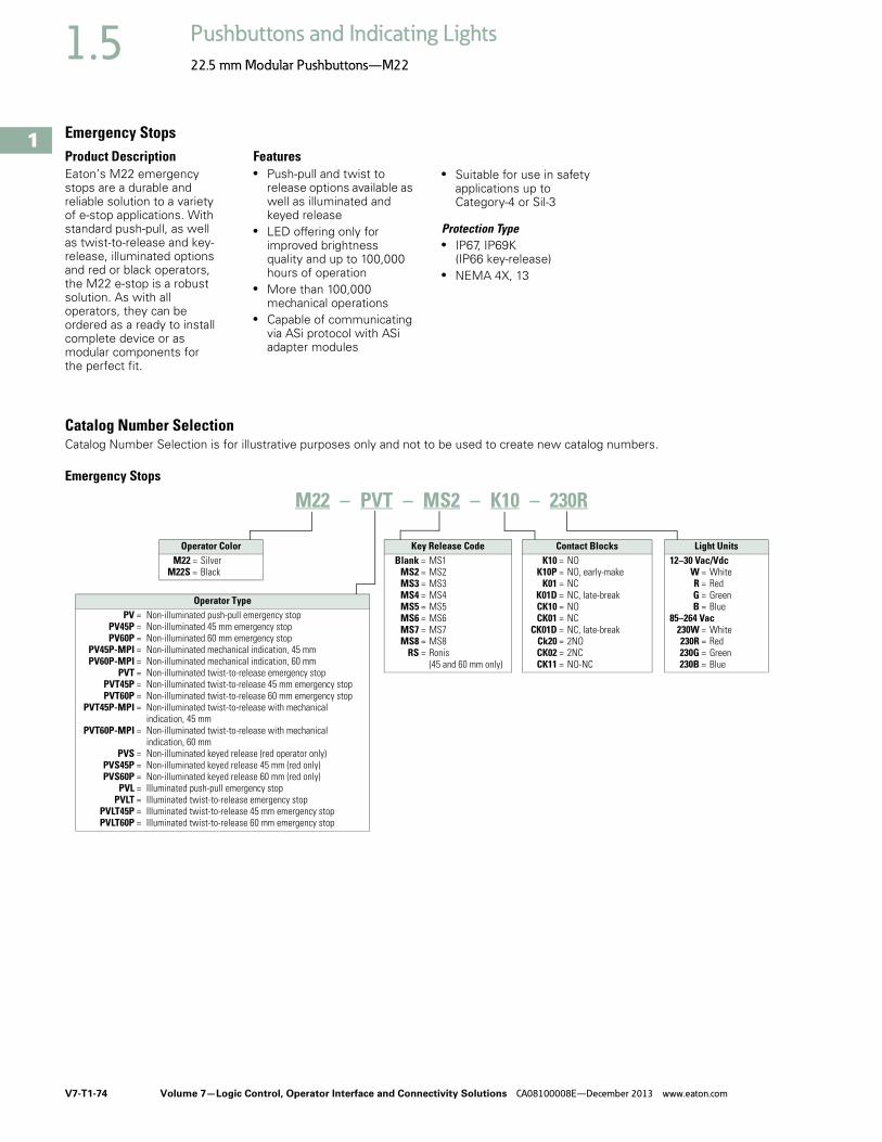
V7-T1-74 Volume 7—Logic Control, Operator Interface and Connectivity Solutions CA08100008E—December 2013 www.eaton.com
1
1
1
1
1
1
1
1
1
1
1
1
1
1
1
1
1
1
1
1
1
1
1
1
1
1
1
1
1
1
1.5 Pushbuttons and Indicating Lights
22.5 mm Modular Pushbuttons—M22
Emergency StopsProduct DescriptionEaton’s M22 emergency stops are a durable and reliable solution to a variety of e-stop applications. With standard push-pull, as well as twist-to-release and key-release, illuminated options and red or black operators, the M22 e-stop is a robust solution. As with all operators, they can be ordered as a ready to install complete device or as modular components for the perfect fit.
Features● Push-pull and twist to
release options available as well as illuminated and keyed release
● LED offering only for improved brightness quality and up to 100,000 hours of operation
● More than 100,000 mechanical operations
● Capable of communicating via ASi protocol with ASi adapter modules
● Suitable for use in safety applications up to Category-4 or Sil-3
Protection Type● IP67, IP69K
(IP66 key-release)● NEMA 4X, 13
Catalog Number SelectionCatalog Number Selection is for illustrative purposes only and not to be used to create new catalog numbers.
Emergency Stops
M22 – PVT – MS2 – K10 – 230R
Operator Color M22 = Silver
M22S = Black
Contact BlocksK10 = NO
K10P = NO, early-makeK01 = NC
K01D = NC, late-breakCK10 = NOCK01 = NC
CK01D = NC, late-breakCk20 = 2NOCK02 = 2NCCK11 = NO-NC
Key Release CodeBlank = MS1
MS2 = MS2MS3 = MS3MS4 = MS4MS5 = MS5MS6 = MS6MS7 = MS7MS8 = MS8
RS = Ronis(45 and 60 mm only)
Light Units12–30 Vac/Vdc
W = WhiteR = RedG = GreenB = Blue
85–264 Vac230W = White230R = Red230G = Green230B = Blue
Operator TypePV = Non-illuminated push-pull emergency stop
PV45P = Non-illuminated 45 mm emergency stopPV60P = Non-illuminated 60 mm emergency stop
PV45P-MPI = Non-illuminated mechanical indication, 45 mmPV60P-MPI = Non-illuminated mechanical indication, 60 mm
PVT = Non-illuminated twist-to-release emergency stopPVT45P = Non-illuminated twist-to-release 45 mm emergency stopPVT60P = Non-illuminated twist-to-release 60 mm emergency stop
PVT45P-MPI = Non-illuminated twist-to-release with mechanical indication, 45 mm
PVT60P-MPI = Non-illuminated twist-to-release with mechanical indication, 60 mm
PVS = Non-illuminated keyed release (red operator only)PVS45P = Non-illuminated keyed release 45 mm (red only)PVS60P = Non-illuminated keyed release 60 mm (red only)
PVL = Illuminated push-pull emergency stopPVLT = Illuminated twist-to-release emergency stop
PVLT45P = Illuminated twist-to-release 45 mm emergency stopPVLT60P = Illuminated twist-to-release 60 mm emergency stop

Volume 7—Logic Control, Operator Interface and Connectivity Solutions CA08100008E—December 2013 www.eaton.com V7-T1-75
1
1
1
1
1
1
1
1
1
1
1
1
1
1
1
1
1
1
1
1
1
1
1
1
1
1
1
1
1
1
1.5Pushbuttons and Indicating Lights
22.5 mm Modular Pushbuttons—M22
Product SelectionNon-Illuminated and Illuminated Emergency Stops
Complete Devices
Note1 All NC contact blocks are positively driven contact.
TypeButton Color
LED Color
Contact BlockConfiguration 1
Light Unit Voltage Catalog Number
Non-Illuminated
Push-pull Red — NC — M22-PV-K01
2NC M22-PV-K02
1NO-2NC M22-PV-K12
Twist-to-release Red — NC — M22-PVT-K01
2NC M22-PVT-K02
1NO-2NC M22-PVT-K12
Key release Red — NC — M22-PVS-K01
2NC M22-PVS-K02
1NO-2NC M22-PVS-K12
Illuminated
Push-pull Red Red NC 12–30 Vac/Vdc M22-PVL-K01-R
2NC M22-PVL-K02-R
1NO-2NC M22-PVL-K12-R
NC 85–264 Vac M22-PVL-K01-230R
2NC M22-PVL-K02-230R
1NO-2NC M22-PVL-K12-230R
Twist-to-release Red Red NC 12–30 Vac/Vdc M22-PVLT-K01-R
2NC M22-PVLT-K02-R
1NO-2NC M22-PVLT-K12-R
NC 85–264 Vac M22-PVLT-K01-230R
2NC M22-PVLT-K02-230R
1NO-2NC M22-PVLT-K12-230R
M22-PV-K01
M22-PVL-K01-R

V7-T1-76 Volume 7—Logic Control, Operator Interface and Connectivity Solutions CA08100008E—December 2013 www.eaton.com
1
1
1
1
1
1
1
1
1
1
1
1
1
1
1
1
1
1
1
1
1
1
1
1
1
1
1
1
1
1
1.5 Pushbuttons and Indicating Lights
22.5 mm Modular Pushbuttons—M22
Non-Illuminated and Illuminated Emergency Stops
Components
Push-Pull Emergency Stops
Twist-to-Release Emergency Stops
Machine Stop Operators (Black) 1
Key Release Emergency Stops 2
Notes1 Includes contact block mounting adapter.2 Key included. For identical locks and keys, use the same key code. One key is included with
actuator; additional keys are available as accessories.3 Includes Key Code MS1.
max. 5mmthickness
Note: Included with operator.
Illumination/IndicationActuatorSize
CatalogNumber
None 35mm M22-PV
45mm M22-PV45P
60mm M22-PV60P
LED illumination 35mm M22-PVL
45mm M22-PVL45P
60mm M22-PVL60P
Mechanical indication 45mm M22-PV45P-MPI
60mm M22-PV60P-MPI
Illumination/IndicationActuatorSize
CatalogNumber
None 35mm M22-PVT
45mm M22-PVT45P
60mm M22-PVT60P
LED illumination 35mm M22-PVLT
45mm M22-PVLT45P
60mm M22-PVLT60P
Mechanical indication 45mm M22-PVT45P-MPI
60mm M22-PVT60P-MPI
Illumination TypeActuatorSize
CatalogNumber
Non-illuminated Push-pull 35mm M22S-PV
Twist-to-release
35mm M22S-PVT
LED illumination Push-pull 35mm M22S-PVL
Twist-to-release
35mm M22S-PVLT
M22-PVL
M22-PVT45P-MPI
M22S-PVLT
ActuatorSize
KeyCode
CatalogNumber
35 mm MS1 M22-PVS 3
MS2 M22-PVS-MS2
MS3 M22-PVS-MS3
MS4 M22-PVS-MS4
MS5 M22-PVS-MS5
MS6 M22-PVS-MS6
MS7 M22-PVS-MS7
MS8 M22-PVS-MS8
45 mm MS1 M22-PVS45P
MS2 M22-PVS45P-MS2
MS3 M22-PVS45P-MS3
MS4 M22-PVS45P-MS4
MS5 M22-PVS45P-MS5
MS6 M22-PVS45P-MS6
MS7 M22-PVS45P-MS7
MS8 M22-PVS45P-MS8
Ronis M22-PVS45P-RS
60 mm MS1 M22-PVS60P
MS2 M22-PVS60P-MS2
MS3 M22-PVS60P-MS3
MS4 M22-PVS60P-MS4
MS5 M22-PVS60P-MS5
MS6 M22-PVS60P-MS6
MS7 M22-PVS60P-MS7
MS8 M22-PVS60P-MS8
Ronis M22-PVS60P-RS
M22-PVS60P-MS1

Volume 7—Logic Control, Operator Interface and Connectivity Solutions CA08100008E—December 2013 www.eaton.com V7-T1-77
1
1
1
1
1
1
1
1
1
1
1
1
1
1
1
1
1
1
1
1
1
1
1
1
1
1
1
1
1
1
1.5Pushbuttons and Indicating Lights
22.5 mm Modular Pushbuttons—M22
Contact Blocks 1
Light Units 1
Extra Keys 4
Accessories
Notes1 For complete listing of available contact blocks, see Accessories,
Pages V7-T1-111 to V7-T1-116. 2 Self-monitoring contact blocks (SMCB type) cannot be used with illuminated emergency
stops.3 All NC contact blocks are positively driven contact. 4 For use with key release operators only. One key included with operator.
TerminalType
MountingLocation 2
Contact Configuration 3 Catalog Number
Screw Front NO M22-K10
NO, early-make M22-K10P
NC M22-K01
NC, late-break M22-K01D
SMCB, NC M22-K01SMC10
SMCB, 2NC M22-K02SMC10
Base SMCB, NC M22-KC01SMC10
SMCB, 2NC M22-KC02SMC10
Spring-cage
Front NO M22-CK10
NC M22-CK01
NC, late-break M22-CK01D
2NO M22-CK20
2NC M22-CK02
NO-NC M22-CK11
TerminalType
LEDColor
Light UnitVoltage Catalog Number
Screw White 12–30 Vac/Vdc M22-LED-W
Red 12–30 Vac/Vdc M22-LED-R
Screw White 85–264 Vac M22-LED230-W
Red 85–264 Vac M22-LED230-R
Screw White 207–264 Vac M22-LED230H-W
Red 207–264 Vac M22-LED230H-R
For Key Code Catalog Number
MS1 M22-ES-MS1
MS2 M22-ES-MS2
MS3 M22-ES-MS3
MS4 M22-ES-MS4
MS5 M22-ES-MS5
MS6 M22-ES-MS6
MS7 M22-ES-MS7
MS8 M22-ES-MS8
M22-K10
M22-LED-W
M22-ES-MS1
Description Voltage Catalog Number
Yellow guard ring — M22-XGPV
Gray guard ring — M22G-XGPV
Rectangular guard — M22-MGTA
Sealing shroud — M22-PL-PV
Illuminated ring 24 Vac/Vdc M22-XPV60-Y-24120 Vac M22-XPV60-Y-120230 Vac M22-XPV60-Y-230
M22-XGPV
M22G-XGPV
M22-PL-PV
M22-MGTA
M22-XPV60-Y-120

V7-T1-78 Volume 7—Logic Control, Operator Interface and Connectivity Solutions CA08100008E—December 2013 www.eaton.com
1
1
1
1
1
1
1
1
1
1
1
1
1
1
1
1
1
1
1
1
1
1
1
1
1
1
1
1
1
1
1.5 Pushbuttons and Indicating Lights
22.5 mm Modular Pushbuttons—M22
Selector Switches ContentsDescription Page
Selector Switches Non-Illuminated Switches . . . . . . . . . . . . . . . . . V7-T1-79
Illuminated Switches . . . . . . . . . . . . . . . . . . . . V7-T1-84
Key Operated . . . . . . . . . . . . . . . . . . . . . . . . . . V7-T1-88
Selector SwitchesProduct DescriptionEaton’s M22 selector switch line offers an almost endless variety of options in maintained/momentary, key-removal and illuminated devices. The coding adapters used for maintained/momentary and key removal positions make the M22 stand out from competitive devices. By simply adding or removing a coding adapter from inside the operator, the end-user can change the function of the button. Operator options include standard knob, rotary head, illuminated and keyed versions. As with all operators, they can be ordered as a ready to install complete device or as modular components to meet application specific requirements.
Features● Adding or removing coding
adapters allows for field convertibility of maintained/momentary and key removal positions
● LED offering only for improved brightness quality and up to 100,000 hours of operation
● More than 100,000 mechanical operations
● Coding adapter options make assembly fast and simplify stocking of different configurations of selector switches
● Capable of communicating via ASi protocol with ASi adapter modules
Protection Type● IP66● NEMA 4X, 13

Volume 7—Logic Control, Operator Interface and Connectivity Solutions CA08100008E—December 2013 www.eaton.com V7-T1-79
1
1
1
1
1
1
1
1
1
1
1
1
1
1
1
1
1
1
1
1
1
1
1
1
1
1
1
1
1
1
1.5Pushbuttons and Indicating Lights
22.5 mm Modular Pushbuttons—M22
Catalog Number SelectionCatalog Number Selection is for illustrative purposes only and not to be used to create new catalog numbers.
Non-Illuminated Selector Switches
Contact BlocksK10 = NO
K10P = NO, early-make
OptionsK11 = NO-NCK22 = 2NO-2NCK20 = 2NOK02 = 2NC
2 Rotary type only.
Inscription 2
X91 = AUTO-HANDX92 = II-I
Bezel M22 = Silver
M22S = Black M22M = Metal
1 All momentary selector switches can be converted in the field to maintained operation with the removal of a color-coded adapter.
Handle Type 1
W = Momentary rotaryWK = Momentary knob
WKV = Maintained V-position knobWR = Maintained rotary
WRK = Maintained knob
Number of PositionsBlank = Two-position
3 = Three-position4 = Four-position
M22 – WRK – X91 – K10–

V7-T1-80 Volume 7—Logic Control, Operator Interface and Connectivity Solutions CA08100008E—December 2013 www.eaton.com
1
1
1
1
1
1
1
1
1
1
1
1
1
1
1
1
1
1
1
1
1
1
1
1
1
1
1
1
1
1
1.5 Pushbuttons and Indicating Lights
22.5 mm Modular Pushbuttons—M22
Product SelectionNon-Illuminated Selector Switches
Complete Devices, Knob Type 1
Notes1 Includes contact block mounting adapter. 2 All NC contact blocks are positively driven contact.
Type Switching PositionContact BlockConfiguration 2
Silver BezelCatalog Number
Black BezelCatalog Number
Metal BezelCatalog Number
Two-position Maintained NO M22-WRK-K10 M22S-WRK-K10 M22M-WRK-K10
1NO-1NC M22-WRK-K11 M22S-WRK-K11 M22M-WRK-K11
2NO-2NC M22-WRK-K22 M22S-WRK-K22 M22M-WRK-K22
Maintained V NO M22-WKV-K10 M22S-WKV-K10 M22M-WKV-K10
1NO-1NC M22-WKV-K11 M22S-WKV-K11 M22M-WKV-K11
2NO-2NC M22-WKV-K22 M22S-WKV-K22 M22M-WKV-K22
Three-position Maintained 2NO M22-WRK3-K20 M22S-WRK3-K20 M22M-WRK3-K20
2NO-2NC M22-WRK3-K22 M22S-WRK3-K22 M22M-WRK3-K22
M22-WKV-K10
M22M-WKV-K10
40°
60°
60° 60°

Volume 7—Logic Control, Operator Interface and Connectivity Solutions CA08100008E—December 2013 www.eaton.com V7-T1-81
1
1
1
1
1
1
1
1
1
1
1
1
1
1
1
1
1
1
1
1
1
1
1
1
1
1
1
1
1
1
1.5Pushbuttons and Indicating Lights
22.5 mm Modular Pushbuttons—M22
Non-Illuminated Selector Switches
Components
Operators Only, Knob Type 1
Notes1 Includes contact block mounting adapter. 2 Momentary selector switches can be converted in the field to maintained operation with the removal of a color
coded adapter. See Page V7-T1-118.
Type Switching PositionSilver BezelCatalog Number
Black BezelCatalog Number
Metal BezelCatalog Number
Two-position Momentary 2 M22-WK M22S-WK M22M-WK
Maintained M22-WRK M22S-WRK M22M-WRK
Maintained V M22-WKV M22S-WKV M22M-WKV
Three-position Momentary 2 M22-WK3 M22S-WK3 M22M-WK3
Maintained M22-WRK3 M22S-WRK3 M22M-WRK3
Maintained, return from left M22-WRK3-2 M22S-WRK3-2 M22M-WRK3-2
Maintained, return from right M22-WRK3-1 M22S-WRK3-1 M22M-WRK3-1
Four-position Maintained M22-WRK4 M22S-WRK4 M22M-WRK4
M22-WK
M22M-WK
40°
40°
60°
40° 40°
60°60°
40° 40° 60°60°
40° 40° 60°60°

V7-T1-82 Volume 7—Logic Control, Operator Interface and Connectivity Solutions CA08100008E—December 2013 www.eaton.com
1
1
1
1
1
1
1
1
1
1
1
1
1
1
1
1
1
1
1
1
1
1
1
1
1
1
1
1
1
1
1.5 Pushbuttons and Indicating Lights
22.5 mm Modular Pushbuttons—M22
Non-Illuminated Selector Switches
Components
Operators Only, Rotary Type 1
Notes1 Includes contact block mounting adapter. 2 Momentary selector switches can be converted in the field to maintained operation with the removal of a color
coded adapter. See Page V7-T1-118.3 When ordering, specify inscription per catalog number suffix from the Symbols Library (see Pages V7-T1-129 to V7-T1-136)
into the Order Notes. For example, M22-WR3-ETCH; Order Notes: Mark with symbol X88, Line item #_.
Type Switching Position InscriptionSilver BezelCatalog Number
Black BezelCatalog Number
Metal BezelCatalog Number
Two-position Momentary 2 I-O M22-W M22S-W M22M-W
Maintained I-O M22-WR M22S-WR M22M-WR
Custom M22-WR-ETCH 3 M22S-WR-ETCH 3 M22M-WR-ETCH 3
AUTO-HAND M22-WR-X91 M22S-WR-X91 M22M-WR-X91
II-I M22-WR-X92 M22S-WR-X92 M22M-WR-X92
Three-position Momentary 2 I-O-II M22-W3 M22S-W3 M22M-W3
Maintained I-O-II M22-WR3 M22S-WR3 M22M-WR3
Custom M22-WR3-ETCH 3 M22S-WR3-ETCH 3 M22M-WR3-ETCH 3
AUTO-O-MAN M22-WR3-X94 M22S-WR3-X94 M22M-WR3-X94
Four-position Maintained 0-1-0-2-0-3-0-4 M22-WR4 M22S-WR4 M22M-WR4
M22S-WR3-X94
40°
40°
40° 40°
60°60°

Volume 7—Logic Control, Operator Interface and Connectivity Solutions CA08100008E—December 2013 www.eaton.com V7-T1-83
1
1
1
1
1
1
1
1
1
1
1
1
1
1
1
1
1
1
1
1
1
1
1
1
1
1
1
1
1
1
1.5Pushbuttons and Indicating Lights
22.5 mm Modular Pushbuttons—M22
Non-Illuminated Selector Switches
Components
Contact Blocks 1 Accessories
Notes1 For complete listing of available contact blocks, see Accessories,
Pages V7-T1-111 to V7-T1-116.2 All NC contact blocks are positively driven contact. 3 Plunger needed to actuate center-mounted contact blocks. Used for non-illuminated
three-position selector switches only.4 Enables a keyed selector switch to be set to user-selected key withdraw position.
max. 5mmthickness
Note: Included with operator.
TerminalType
Contact Configuration 2 Catalog Number
Screw NO M22-K10NO, early-make M22-K10PNC M22-K01NC, late-break M22-K01D
Spring-cage NO M22-CK10NC M22-CK01NC, late-break M22-CK01D2NO M22-CK202NC M22-CK02NO-NC M22-CK11
M22-K10Description Catalog Number
Plunger bridge 3 M22-XW
Key cover M22-XWS
Key withdraw adapter 4 M22-XC-R
Coding adapter M22-XC-Y
Guard ring M22-XGWK
M22-XC-Y
M22-XWS
M22-XC-R
M22-XW
M22-XGWK

V7-T1-84 Volume 7—Logic Control, Operator Interface and Connectivity Solutions CA08100008E—December 2013 www.eaton.com
1
1
1
1
1
1
1
1
1
1
1
1
1
1
1
1
1
1
1
1
1
1
1
1
1
1
1
1
1
1
1.5 Pushbuttons and Indicating Lights
22.5 mm Modular Pushbuttons—M22
Catalog Number SelectionCatalog Number Selection is for illustrative purposes only and not to be used to create new catalog numbers.
Illuminated Selector Switches
Handle Type WLK = Illuminated knob type
momentary, two-positionWLKV = Illuminated Knob type
momentary, V-positionWLK3 = Illuminated knob type
momentary, three-position
M22 – WLK – R – K10 – R
Light Units12–30 Vac/Vdc
W = WhiteR = RedG = GreenB = Blue
85–264 Vac230W = White230R = Red230G = Green230B = Blue
Contact BlocksK10 = 1NOK01 = 1NCK20 = 2NOK02 = 2NCK11 = 1NO-1NC
K30 = 3NOK03 = 3NCK21 = 2NO-1NCK12 = 1NO-2NC
Handle ColorW = WhiteR = RedG = GreenY = YellowB = Blue
Bezel M22 = Silver
M22S = Black M22M = Metal

Volume 7—Logic Control, Operator Interface and Connectivity Solutions CA08100008E—December 2013 www.eaton.com V7-T1-85
1
1
1
1
1
1
1
1
1
1
1
1
1
1
1
1
1
1
1
1
1
1
1
1
1
1
1
1
1
1
1.5Pushbuttons and Indicating Lights
22.5 mm Modular Pushbuttons—M22
Product SelectionIlluminated Selector Switches
Components
Operators Only, Knob Type 1
Notes1 Includes contact block mounting adapter. 2 Momentary selector switches can be converted in the field to maintained operation with the removal of a color coded
adapter. See Page V7-T1-118.
Type Switching Position Button ColorSilver BezelCatalog Number
Black BezelCatalog Number
Metal BezelCatalog Number
Two-position Momentary 2 White M22-WLK-W M22S-WLK-W M22M-WLK-W
Red M22-WLK-R M22S-WLK-R M22M-WLK-R
Green M22-WLK-G M22S-WLK-G M22M-WLK-G
Yellow M22-WLK-Y M22S-WLK-Y M22M-WLK-Y
Blue M22-WLK-B M22S-WLK-B M22M-WLK-B
Maintained White M22-WRLK-W M22S-WRLK-W M22M-WRLK-W
Red M22-WRLK-R M22S-WRLK-R M22M-WRLK-R
Green M22-WRLK-G M22S-WRLK-G M22M-WRLK-G
Yellow M22-WRLK-Y M22S-WRLK-Y M22M-WRLK-Y
Blue M22-WRLK-B M22S-WRLK-B M22M-WRLK-B
Maintained V White M22-WLKV-W M22S-WLKV-W M22M-WLKV-W
Red M22-WLKV-R M22S-WLKV-R M22M-WLKV-R
Green M22-WLKV-G M22S-WLKV-G M22M-WLKV-G
Yellow M22-WLKV-Y M22S-WLKV-Y M22M-WLKV-Y
Blue M22-WLKV-B M22S-WLKV-B M22M-WLKV-B
M22-WLK-W
40°
40°
60°

V7-T1-86 Volume 7—Logic Control, Operator Interface and Connectivity Solutions CA08100008E—December 2013 www.eaton.com
1
1
1
1
1
1
1
1
1
1
1
1
1
1
1
1
1
1
1
1
1
1
1
1
1
1
1
1
1
1
1.5 Pushbuttons and Indicating Lights
22.5 mm Modular Pushbuttons—M22
Illuminated Selector Switches
Components
Operators Only, Knob Type 1
Notes1 Includes contact block mounting adapter. 2 Momentary selector switches can be converted in the field to maintained operation with the removal of a color coded
adapter. See Page V7-T1-118.
Type Switching Position Button ColorSilver BezelCatalog Number
Black BezelCatalog Number
Metal BezelCatalog Number
Three-position Momentary 2 White M22-WLK3-W M22S-WLK3-W M22M-WLK3-W
Red M22-WLK3-R M22S-WLK3-R M22M-WLK3-R
Green M22-WLK3-G M22S-WLK3-G M22M-WLK3-G
Yellow M22-WLK3-Y M22S-WLK3-Y M22M-WLK3-Y
Blue M22-WLK3-B M22S-WLK3-B M22M-WLK3-B
Maintained White M22-WRLK3-W M22S-WRLK3-W M22M-WRLK3-W
Red M22-WRLK3-R M22S-WRLK3-R M22M-WRLK3-R
Green M22-WRLK3-G M22S-WRLK3-G M22M-WRLK3-G
Yellow M22-WRLK3-Y M22S-WRLK3-Y M22M-WRLK3-Y
Blue M22-WRLK3-B M22S-WRLK3-B M22M-WRLK3-B
Maintained, return from right White M22-WRLK3-1-W M22S-WRLK3-1-W M22M-WRLK3-1-W
Red M22-WRLK3-1-R M22S-WRLK3-1-R M22M-WRLK3-1-R
Green M22-WRLK3-1-G M22S-WRLK3-1-G M22M-WRLK3-1-G
Yellow M22-WRLK3-1-Y M22S-WRLK3-1-Y M22M-WRLK3-1-Y
Blue M22-WRLK3-1-B M22S-WRLK3-1-B M22M-WRLK3-1-B
Maintained, return from left White M22-WRLK3-2-W M22S-WRLK3-2-W M22M-WRLK3-2-W
Red M22-WRLK3-2-R M22S-WRLK3-2-R M22M-WRLK3-2-R
Green M22-WRLK3-2-G M22S-WRLK3-2-G M22M-WRLK3-2-G
Yellow M22-WRLK3-2-Y M22S-WRLK3-2-Y M22M-WRLK3-2-Y
Blue M22-WRLK3-2-B M22S-WRLK3-2-B M22M-WRLK3-2-B
M22-WLK3-W
40° 40°
60°60°
40° 40° 60°60°
40° 40° 60°60°

Volume 7—Logic Control, Operator Interface and Connectivity Solutions CA08100008E—December 2013 www.eaton.com V7-T1-87
1
1
1
1
1
1
1
1
1
1
1
1
1
1
1
1
1
1
1
1
1
1
1
1
1
1
1
1
1
1
1.5Pushbuttons and Indicating Lights
22.5 mm Modular Pushbuttons—M22
Illuminated Selector Switches
Light Units 1 5
Contact Blocks 1
Accessories
Notes1 For complete listing of available light units and contact blocks, see Accessories,
Pages V7-T1-111 to V7-T1-116.2 Plunger needed to actuate center-mounted contact blocks. Used for non-illuminated
three-position selector switches only.3 All NC contact blocks are positively driven contact. 4 Enables a keyed selector switch to be set to user-selected key withdraw position.5 Select the same color LED element as lens color; for yellow lens, choose a white LED.
max. 5mmthickness
Note: Included with operator.
TerminalType
LED Color
Light UnitVoltage Catalog Number
Screw White 12–30 Vac/Vdc
M22-LED-WRed M22-LED-RGreen M22-LED-GBlue M22-LED-B
Screw White 85–264 Vac
M22-LED230-WRed M22-LED230-RGreen M22-LED230-GBlue M22-LED230-B
TerminalType
Contact Configuration 3 Catalog Number
Screw NO M22-K10NO, early-make M22-K10PNC M22-K01NC, late-break M22-K01D
Spring-cage NO M22-CK10NC M22-CK01NC, late-break M22-CK01D2NO M22-CK202NC M22-CK02NO-NC M22-CK11
M22-LED-W
M22-K10
Description Catalog Number
Plunger bridge 2 M22-XW
Key cover M22-XWS
Key withdraw adapter 4 M22-XC-R
Coding adapter M22-XC-Y
Guard ring M22-XGWK
M22-XC-Y
M22-XWS
M22-XC-R
M22-XW
M22-XGWK

V7-T1-88 Volume 7—Logic Control, Operator Interface and Connectivity Solutions CA08100008E—December 2013 www.eaton.com
1
1
1
1
1
1
1
1
1
1
1
1
1
1
1
1
1
1
1
1
1
1
1
1
1
1
1
1
1
1
1.5 Pushbuttons and Indicating Lights
22.5 mm Modular Pushbuttons—M22
Catalog Number SelectionCatalog Number Selection is for illustrative purposes only and not to be used to create new catalog numbers.
Key-Operated Selector Switches
Product SelectionKey-Operated Selector Switches 12
Components
Operators Only 3
Notes1 Includes one key.2 Key removal positions can be modified in the field using coding adapters; see chart on Page V7-T1-118. 3 Includes contact block mounting adapter.4 Momentary selector switches can be converted in the field to maintained operation with the removal of a color coded adapter. See Page V7-T1-118.
Bezel M22 = Silver
M22S = Black M22M = Metal
M22 – WS – MS2 – A1
Key CodeBlank = MS1
MS2 = MS2MS3 = MS3MS4 = MS4MS5 = MS5MS6 = MS6MS7 = MS7MS8 = MS8
Handle TypeWS = Two-position, momentary
WS3 = Three-position, momentaryWRS = Two-position, maintained
WRS3 = Three-position, maintained
Key Removal PositionRefer to coding adapter assembly and functional test guide on Page V7-T1-118.
Type Switching Position Key Removal Position Key CodeSilver BezelCatalog Number
Black BezelCatalog Number
Metal BezelCatalog Number
Two-position Momentary 4 Return from right, key removable left
MS1 M22-WS M22S-WS M22M-WS
MS2 M22-WS-MS2 M22S-WS-MS2 M22M-WS-MS2
MS3 M22-WS-MS3 M22S-WS-MS3 M22M-WS-MS3
MS4 M22-WS-MS4 M22S-WS-MS4 M22M-WS-MS4
MS5 M22-WS-MS5 M22S-WS-MS5 M22M-WS-MS5
MS6 M22-WS-MS6 M22S-WS-MS6 M22M-WS-MS6
MS7 M22-WS-MS7 M22S-WS-MS7 M22M-WS-MS7
MS8 M22-WS-MS8 M22S-WS-MS8 M22M-WS-MS8
Two-position Maintained Key removable left MS1 M22-WRS-A1 M22S-WRS-A1 M22M-WRS-A1
MS2 M22-WRS-MS2-A1 M22S-WRS-MS2-A1 M22M-WRS-MS2-A1
MS3 M22-WRS-MS3-A1 M22S-WRS-MS3-A1 M22M-WRS-MS3-A1
MS4 M22-WRS-MS4-A1 M22S-WRS-MS4-A1 M22M-WRS-MS4-A1
MS5 M22-WRS-MS5-A1 M22S-WRS-MS5-A1 M22M-WRS-MS5-A1
MS6 M22-WRS-MS6-A1 M22S-WRS-MS6-A1 M22M-WRS-MS6-A1
MS7 M22-WRS-MS7-A1 M22S-WRS-MS7-A1 M22M-WRS-MS7-A1
MS8 M22-WRS-MS8-A1 M22S-WRS-MS8-A1 M22M-WRS-MS8-A1
Key removable left/right MS1 M22-WRS M22S-WRS M22M-WRS
MS2 M22-WRS-MS2 M22S-WRS-MS2 M22M-WRS-MS2
MS3 M22-WRS-MS3 M22S-WRS-MS3 M22M-WRS-MS3
MS4 M22-WRS-MS4 M22S-WRS-MS4 M22M-WRS-MS4
MS5 M22-WRS-MS5 M22S-WRS-MS5 M22M-WRS-MS5
MS6 M22-WRS-MS6 M22S-WRS-MS6 M22M-WRS-MS6
MS7 M22-WRS-MS7 M22S-WRS-MS7 M22M-WRS-MS7
MS8 M22-WRS-MS8 M22S-WRS-MS8 M22M-WRS-MS8
M22-WS
M22S-WRS
40°
40°

Volume 7—Logic Control, Operator Interface and Connectivity Solutions CA08100008E—December 2013 www.eaton.com V7-T1-89
1
1
1
1
1
1
1
1
1
1
1
1
1
1
1
1
1
1
1
1
1
1
1
1
1
1
1
1
1
1
1.5Pushbuttons and Indicating Lights
22.5 mm Modular Pushbuttons—M22
Key-Operated Selector Switches 12
ComponentsOperators Only, continued 3
Notes1 Includes one key.2 Key removal positions can be modified in the field using coding adapters; see chart on Page V7-T1-118. 3 Includes contact block mounting adapter.4 Momentary selector switches can be converted in the field to maintained operation with the removal of a color coded adapter. See Page V7-T1-118.
Type Switching Position Key Removal Position Key CodeSilver BezelCatalog Number
Black BezelCatalog Number
Metal BezelCatalog Number
Three-position Momentary 4 Return from left/right, key removable center
MS1 M22-WS3 M22S-WS3 M22M-WS3
MS2 M22-WS3-MS2 M22S-WS3-MS2 M22M-WS3-MS2
MS3 M22-WS3-MS3 M22S-WS3-MS3 M22M-WS3-MS3
MS4 M22-WS3-MS4 M22S-WS3-MS4 M22M-WS3-MS4
MS5 M22-WS3-MS5 M22S-WS3-MS5 M22M-WS3-MS5
MS6 M22-WS3-MS6 M22S-WS3-MS6 M22M-WS3-MS6
MS7 M22-WS3-MS7 M22S-WS3-MS7 M22M-WS3-MS7
MS8 M22-WS3-MS8 M22S-WS3-MS8 M22M-WS3-MS8
Three-position Maintained Key removable left/center/right
MS1 M22-WRS3-A1 M22S-WRS3-A1 M22M-WRS3-A1
MS2 M22-WRS3-MS2-A1 M22S-WRS3-MS2-A1 M22M-WRS3-MS2-A1
MS3 M22-WRS3-MS3-A1 M22S-WRS3-MS3-A1 M22M-WRS3-MS3-A1
MS4 M22-WRS3-MS4-A1 M22S-WRS3-MS4-A1 M22M-WRS3-MS4-A1
MS5 M22-WRS3-MS5-A1 M22S-WRS3-MS5-A1 M22M-WRS3-MS5-A1
MS6 M22-WRS3-MS6-A1 M22S-WRS3-MS6-A1 M22M-WRS3-MS6-A1
MS7 M22-WRS3-MS7-A1 M22S-WRS3-MS7-A1 M22M-WRS3-MS7-A1
MS8 M22-WRS3-MS8-A1 M22S-WRS3-MS8-A1 M22M-WRS3-MS8-A1
Key removable center/left
MS1 M22-WRS3-A2 M22S-WRS3-A2 M22M-WRS3-A2
MS2 M22-WRS3-MS2-A2 M22S-WRS3-MS2-A2 M22M-WRS3-MS2-A2
MS3 M22-WRS3-MS3-A2 M22S-WRS3-MS3-A2 M22M-WRS3-MS3-A2
MS4 M22-WRS3-MS4-A2 M22S-WRS3-MS4-A2 M22M-WRS3-MS4-A2
MS5 M22-WRS3-MS5-A2 M22S-WRS3-MS5-A2 M22M-WRS3-MS5-A2
MS6 M22-WRS3-MS6-A2 M22S-WRS3-MS6-A2 M22M-WRS3-MS6-A2
MS7 M22-WRS3-MS7-A2 M22S-WRS3-MS7-A2 M22M-WRS3-MS7-A2
MS8 M22-WRS3-MS8-A2 M22S-WRS3-MS8-A2 M22M-WRS3-MS8-A2
Key removable center/right
MS1 M22-WRS3-A3 M22S-WRS3-A3 M22M-WRS3-A3
MS2 M22-WRS3-MS2-A3 M22S-WRS3-MS2-A3 M22M-WRS3-MS2-A3
MS3 M22-WRS3-MS3-A3 M22S-WRS3-MS3-A3 M22M-WRS3-MS3-A3
MS4 M22-WRS3-MS4-A3 M22S-WRS3-MS4-A3 M22M-WRS3-MS4-A3
MS5 M22-WRS3-MS5-A3 M22S-WRS3-MS5-A3 M22M-WRS3-MS5-A3
MS6 M22-WRS3-MS6-A3 M22S-WRS3-MS6-A3 M22M-WRS3-MS6-A3
MS7 M22-WRS3-MS7-A3 M22S-WRS3-MS7-A3 M22M-WRS3-MS7-A3
MS8 M22-WRS3-MS8-A3 M22S-WRS3-MS8-A3 M22M-WRS3-MS8-A3
Key removable left/right
MS1 M22-WRS3 M22S-WRS3 M22M-WRS3
MS2 M22-WRS3-MS2 M22S-WRS3-MS2 M22M-WRS3-MS2
MS3 M22-WRS3-MS3 M22S-WRS3-MS3 M22M-WRS3-MS3
MS4 M22-WRS3-MS4 M22S-WRS3-MS4 M22M-WRS3-MS4
MS5 M22-WRS3-MS5 M22S-WRS3-MS5 M22M-WRS3-MS5
MS6 M22-WRS3-MS6 M22S-WRS3-MS6 M22M-WRS3-MS6
MS7 M22-WRS3-MS7 M22S-WRS3-MS7 M22M-WRS3-MS7
MS8 M22-WRS3-MS8 M22S-WRS3-MS8 M22M-WRS3-MS8
M22-WS3-X93
M22M-WS3-X93
40° 40°
60°60°

V7-T1-90 Volume 7—Logic Control, Operator Interface and Connectivity Solutions CA08100008E—December 2013 www.eaton.com
1
1
1
1
1
1
1
1
1
1
1
1
1
1
1
1
1
1
1
1
1
1
1
1
1
1
1
1
1
1
1.5 Pushbuttons and Indicating Lights
22.5 mm Modular Pushbuttons—M22
Key-Operated Selector Switches 12
Components
Operators Only, continued 3
Notes1 Includes one key.2 Key removal positions can be modified in the field using coding adapters; see chart on Page V7-T1-118. 3 Includes contact block mounting adapter.
Type Switching PositionKey Removal Position Key Code
Silver BezelCatalog Number
Black BezelCatalog Number
Metal BezelCatalog Number
Three-position Maintained Return from left, key removable center
MS1 M22-WRS3-A7 M22S-WRS3-A7 M22M-WRS3-A7
MS2 M22-WRS3-MS2-A7 M22S-WRS3-MS2-A7 M22M-WRS3-MS2-A7
MS3 M22-WRS3-MS3-A7 M22S-WRS3-MS3-A7 M22M-WRS3-MS3-A7
MS4 M22-WRS3-MS4-A7 M22S-WRS3-MS4-A7 M22M-WRS3-MS4-A7
MS5 M22-WRS3-MS5-A7 M22S-WRS3-MS5-A7 M22M-WRS3-MS5-A7
MS6 M22-WRS3-MS6-A7 M22S-WRS3-MS6-A7 M22M-WRS3-MS6-A7
MS7 M22-WRS3-MS7-A7 M22S-WRS3-MS7-A7 M22M-WRS3-MS7-A7
MS8 M22-WRS3-MS8-A7 M22S-WRS3-MS8-A7 M22M-WRS3-MS8-A7
Return from left, key removable center/right
MS1 M22-WRS3-A6 M22S-WRS3-A6 M22M-WRS3-A6
MS2 M22-WRS3-MS2-A6 M22S-WRS3-MS2-A6 M22M-WRS3-MS2-A6
MS3 M22-WRS3-MS3-A6 M22S-WRS3-MS3-A6 M22M-WRS3-MS3-A6
MS4 M22-WRS3-MS4-A6 M22S-WRS3-MS4-A6 M22M-WRS3-MS4-A6
MS5 M22-WRS3-MS5-A6 M22S-WRS3-MS5-A6 M22M-WRS3-MS5-A6
MS6 M22-WRS3-MS6-A6 M22S-WRS3-MS6-A6 M22M-WRS3-MS6-A6
MS7 M22-WRS3-MS7-A6 M22S-WRS3-MS7-A6 M22M-WRS3-MS7-A6
MS8 M22-WRS3-MS8-A6 M22S-WRS3-MS8-A6 M22M-WRS3-MS8-A6
Three-position Maintained Return from right, key removable left/center
MS1 M22-WRS3-A4 M22S-WRS3-A4 M22M-WRS3-A4
MS2 M22-WRS3-MS2-A4 M22S-WRS3-MS2-A4 M22M-WRS3-MS2-A4
MS3 M22-WRS3-MS3-A4 M22S-WRS3-MS3-A4 M22M-WRS3-MS3-A4
MS4 M22-WRS3-MS4-A4 M22S-WRS3-MS4-A4 M22M-WRS3-MS4-A4
MS5 M22-WRS3-MS5-A4 M22S-WRS3-MS5-A4 M22M-WRS3-MS5-A4
MS6 M22-WRS3-MS6-A4 M22S-WRS3-MS6-A4 M22M-WRS3-MS6-A4
MS7 M22-WRS3-MS7-A4 M22S-WRS3-MS7-A4 M22M-WRS3-MS7-A4
MS8 M22-WRS3-MS8-A4 M22S-WRS3-MS8-A4 M22M-WRS3-MS8-A4
Return from right, key removable center
MS1 M22-WRS3-A5 M22S-WRS3-A5 M22M-WRS3-A5
MS2 M22-WRS3-MS2-A5 M22S-WRS3-MS2-A5 M22M-WRS3-MS2-A5
MS3 M22-WRS3-MS3-A5 M22S-WRS3-MS3-A5 M22M-WRS3-MS3-A5
MS4 M22-WRS3-MS4-A5 M22S-WRS3-MS4-A5 M22M-WRS3-MS4-A5
MS5 M22-WRS3-MS5-A5 M22S-WRS3-MS5-A5 M22M-WRS3-MS5-A5
MS6 M22-WRS3-MS6-A5 M22S-WRS3-MS6-A5 M22M-WRS3-MS6-A5
MS7 M22-WRS3-MS7-A5 M22S-WRS3-MS7-A5 M22M-WRS3-MS7-A5
MS8 M22-WRS3-MS8-A5 M22S-WRS3-MS8-A5 M22M-WRS3-MS8-A5
M22-WS3-X93
M22M-WS3-X93
60°60°
60°60°

Volume 7—Logic Control, Operator Interface and Connectivity Solutions CA08100008E—December 2013 www.eaton.com V7-T1-91
1
1
1
1
1
1
1
1
1
1
1
1
1
1
1
1
1
1
1
1
1
1
1
1
1
1
1
1
1
1
1.5Pushbuttons and Indicating Lights
22.5 mm Modular Pushbuttons—M22
Key-Operated Selector Switches
Components
Contact Blocks 1
Extra Keys
Accessories
Notes1 For complete listing of available contact blocks, see Accessories,
Pages V7-T1-111 to V7-T1-116.2 All NC contact blocks are positively driven contact. 3 Plunger needed to actuate center-mounted contact blocks. Used for non-illuminated
three-position selector switches only.4 Enables a keyed selector switch to be set to user-selected key withdraw position.
max. 5mmthickness
Note: Included with operator.
TerminalType
Contact Configuration 2 Catalog Number
Screw NO M22-K10NO, early-make M22-K10PNC M22-K01NC, late-break M22-K01D
Spring-cage NO M22-CK10NC M22-CK01NC, late-break M22-CK01D2NO M22-CK202NC M22-CK02NO-NC M22-CK11
Key Code Catalog Number
MS1 M22-ES-MS1MS2 M22-ES-MS2MS3 M22-ES-MS3MS4 M22-ES-MS4MS5 M22-ES-MS5MS6 M22-ES-MS6MS7 M22-ES-MS7MS8 M22-ES-MS8
M22-K10
M22-ES-MS1
Description Catalog Number
Plunger bridge 3 M22-XW
Key cover M22-XWS
Key withdraw adapter 4 M22-XC-R
Coding adapter M22-XC-Y
Guard ring M22-XGWK
M22-XC-Y
M22-XWS
M22-XC-R
M22-XW
M22-XGWK
V7-T1-92 Volume 7—Logic Control, Operator Interface and Connectivity Solutions CA08100008E—December 2013 www.eaton.com
1
1
1
1
1
1
1
1
1
1
1
1
1
1
1
1
1
1
1
1
1
1
1
1
1
1
1
1
1
1
1.5 Pushbuttons and Indicating Lights
22.5 mm Modular Pushbuttons—M22
Mushroom Head PushbuttonsProduct DescriptionEaton’s M22 mushroom head operators are a durable and unique way to include standard pushbutton functionality. Like the standard pushbutton line, the maintained pushbuttons are field convertible to momentary. They also offer laser engraving and a robust five million mechanical operations on the standard momentary operator. As with all operators, they can be ordered as a ready to install complete device or as modular components.
Features● Field convertible from
maintained to momentary (available on maintained pushbuttons only)
● Customizable laser engraving on all buttons
● More than five million mechanical operations on momentary and one million on maintained pushbuttons
● Modular construction makes assembly fast and simplifies stocking of components and complete devices
● Capable of communicating via ASi protocol with ASi adapter modules
Protection Type● IP67, IP69K● NEMA 4X, 13

Volume 7—Logic Control, Operator Interface and Connectivity Solutions CA08100008E—December 2013 www.eaton.com V7-T1-93
1
1
1
1
1
1
1
1
1
1
1
1
1
1
1
1
1
1
1
1
1
1
1
1
1
1
1
1
1
1
1.5Pushbuttons and Indicating Lights
22.5 mm Modular Pushbuttons—M22
Catalog Number SelectionCatalog Number Selection is for illustrative purposes only and not to be used to create new catalog numbers.
Mushroom Head Pushbuttons
BezelM22 = Silver
M22S = BlackM22M = Metal
Operator TypeDP = Non-illuminated momentary
mushroom head pushbuttonDRP = Non-illuminated maintained
mushroom head pushbutton
Operator ColorR = RedS = BlackG = GreenY = Yellow 1 When ordering, specify inscription per
catalog number suffix from the Symbols Library (see Pages V7-T1-129 to V7-T1-136) into the Order Notes. For example, M22-DP-R-ETCH;Order Notes: Mark with symbol X91, Line item #_.
Plate Inscription
ETCH = Custom 1GB0 = STOPGB1 = STARTGB3 = UPGB4 = DOWNGB5 = OFFGB6 = ON
GB15 = FORWARDGB16 = REVERSE
X0 = X1 = X4 = X5 = X6 = X7 =
M22 – DP – R – GB4 – K01
Contact BlocksK01 = NCK10 = NOK11 = NO-NCK12 = 1NO-2NC

V7-T1-94 Volume 7—Logic Control, Operator Interface and Connectivity Solutions CA08100008E—December 2013 www.eaton.com
1
1
1
1
1
1
1
1
1
1
1
1
1
1
1
1
1
1
1
1
1
1
1
1
1
1
1
1
1
1
1.5 Pushbuttons and Indicating Lights
22.5 mm Modular Pushbuttons—M22
Product SelectionMushroom Head Pushbuttons, Momentary 1
Complete Devices
Operators Only 2
Notes1 35 mm diameter mushroom head button. 2 Includes contact block mounting adapter.
Button Color
Contact BlockConfiguration 2
Silver BezelCatalog Number
Black BezelCatalog Number
Metal BezelCatalog Number
Red NC M22-DP-R-K01 M22S-DP-R-K01 M22M-DP-R-K01
2NC M22-DP-R-K02 M22S-DP-R-K02 M22M-DP-R-K02
1NO-2NC M22-DP-R-K12 M22S-DP-R-K12 M22M-DP-R-K12
1NO-1NC M22-DP-R-K11 M22S-DP-R-K11 M22M-DP-R-K11
Button ColorSilver BezelCatalog Number
Black BezelCatalog Number
Metal BezelCatalog Number
Black M22-DP-S M22S-DP-S M22M-DP-S
Red M22-DP-R M22S-DP-R M22M-DP-R
Green M22-DP-G M22S-DP-G M22M-DP-G
Yellow M22-DP-Y M22S-DP-Y M22M-DP-Y
M22-DP-R-K01
M22S-DP-R-K01
M22M-DP-R-K01
M22-DP-G
M22S-DP-G
M22M-DP-G
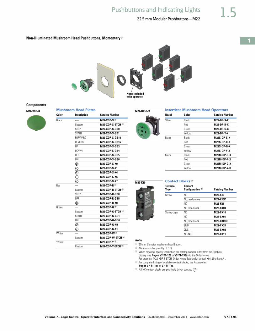
Volume 7—Logic Control, Operator Interface and Connectivity Solutions CA08100008E—December 2013 www.eaton.com V7-T1-95
1
1
1
1
1
1
1
1
1
1
1
1
1
1
1
1
1
1
1
1
1
1
1
1
1
1
1
1
1
1
1.5Pushbuttons and Indicating Lights
22.5 mm Modular Pushbuttons—M22
Non-Illuminated Mushroom Head Pushbuttons, Momentary 1
ComponentsMushroom Head Plates Insertless Mushroom Head Operators
Contact Blocks 4
Notes1 35 mm diameter mushroom head button. 2 Minimum order quantity of (10).3 When ordering, specify inscription per catalog number suffix from the Symbols
Library (see Pages V7-T1-129 to V7-T1-136) into the Order Notes. For example, M22-XDP-S-ETCH; Order Notes: Mark with symbol X91, Line item #_.
4 For complete listing of available contact blocks, see Accessories, Pages V7-T1-111 to V7-T1-116.
5 All NC contact blocks are positively driven contact.
Note: Included with operator.
Color Inscription Catalog Number
Black -— M22-XDP-S 2
Custom M22-XDP-S-ETCH 3
STOP M22-XDP-S-GB0START M22-XDP-S-GB1FORWARD M22-XDP-S-GB15REVERSE M22-XDP-S-GB16UP M22-XDP-S-GB3DOWN M22-XDP-S-GB4OFF M22-XDP-S-GB5ON M22-XDP-S-GB6
M22-XDP-S-X0M22-XDP-S-X1M22-XDP-S-X4M22-XDP-S-X5M22-XDP-S-X7
Red — M22-XDP-R 2
Custom M22-XDP-R-ETCH 3
STOP M22-XDP-R-GB0OFF M22-XDP-R-GB5
M22-XDP-R-X0Green — M22-XDP-G 2
Custom M22-XDP-G-ETCH 3
START M22-XDP-G-GB1ON M22-XDP-G-GB6
M22-XDP-G-X0M22-XDP-G-X1
White — M22-XDP-W 2
Custom M22-XDP-W-ETCH 3
Yellow — M22-XDP-Y 2
Custom M22-XDP-Y-ETCH 3
M22-XDP-GBezel Color Catalog Number
Silver Black M22-DP-S-XRed M22-DP-R-XGreen M22-DP-G-XYellow M22-DP-Y-X
Black Black M22S-DP-S-XRed M22S-DP-R-XGreen M22S-DP-G-XYellow M22S-DP-Y-X
Metal Black M22M-DP-S-XRed M22M-DP-R-XGreen M22M-DP-G-XYellow M22M-DP-Y-X
TerminalType
Contact Configuration 5 Catalog Number
Screw NO M22-K10NO, early-make M22-K10PNC M22-K01NC, late-break M22-K01D
Spring-cage NO M22-CK10NC M22-CK01NC, late-break M22-CK01D2NO M22-CK202NC M22-CK02NO-NC M22-CK11
M22-DP-G-X
M22-K10

V7-T1-96 Volume 7—Logic Control, Operator Interface and Connectivity Solutions CA08100008E—December 2013 www.eaton.com
1
1
1
1
1
1
1
1
1
1
1
1
1
1
1
1
1
1
1
1
1
1
1
1
1
1
1
1
1
1
1.5 Pushbuttons and Indicating Lights
22.5 mm Modular Pushbuttons—M22
Product SelectionNon-Illuminated Mushroom Head Pushbuttons, Maintained 1 2
Complete Devices
Operators Only
Notes1 35 mm diameter mushroom head button. 2 Maintained pushbuttons can be converted in the field to momentary operation by switching the locking ring,
which is accessible through the side of the operator body.3 All NC contact blocks are positively driven contact.
Note: This pilot device features a selectable function switch that enables the device to be set to either maintained or momentary operation.
Button Color
Contact BlockConfiguration 2
Silver BezelCatalog Number
Black BezelCatalog Number
Metal BezelCatalog Number
Red NC M22-DRP-R-K01 M22S-DRP-R-K01 M22M-DRP-R-K01
2NC M22-DRP-R-K02 M22S-DRP-R-K02 M22M-DRP-R-K02
1NO-2NC M22-DRP-R-K12 M22S-DRP-R-K12 M22M-DRP-R-K12
1NO-1NC M22-DRP-R-K11 M22S-DRP-R-K11 M22M-DRP-R-K11
Button ColorSilver BezelCatalog Number
Black BezelCatalog Number
Metal BezelCatalog Number
Black M22-DRP-S M22S-DRP-S M22M-DRP-S
Red M22-DRP-R M22S-DRP-R M22M-DRP-R
Green M22-DRP-G M22S-DRP-G M22M-DRP-G
Yellow M22-DRP-Y M22S-DRP-Y M22M-DRP-Y
M22-DRP-R-K01
M22S-DRP-R-K01
M22M-DRP-R-K01
M22-DRP-G
M22S-DRP-G
M22M-DRP-G

Volume 7—Logic Control, Operator Interface and Connectivity Solutions CA08100008E—December 2013 www.eaton.com V7-T1-97
1
1
1
1
1
1
1
1
1
1
1
1
1
1
1
1
1
1
1
1
1
1
1
1
1
1
1
1
1
1
1.5Pushbuttons and Indicating Lights
22.5 mm Modular Pushbuttons—M22
Non-Illuminated Mushroom Head Pushbuttons, Maintained 12
ComponentsMushroom Head Plates 5 Insertless Mushroom Head Operators
Contact Blocks 5
Notes1 35 mm diameter mushroom head button. 2 Maintained pushbuttons can be converted in the field to momentary operation by
switching the locking ring, which is accessible through the side of the operator body.3 Minimum order quantity of (10).4 When ordering, specify inscription per catalog number suffix from the Symbols
Library (see Pages V7-T1-129 to V7-T1-136) into the Order Notes. For example, M22-XDP-S-ETCH; Order Notes: Mark with symbol X91, Line item #_.
5 For complete listing of available button plates and contact blocks, see Accessories, Pages V7-T1-111 to V7-T1-116.
6 All NC contact blocks are positively driven contact.
Note: Included with operator.
Color Inscription Catalog Number
Black — M22-XDP-S 3
Custom M22-XDP-S-ETCH 4
STOP M22-XDP-S-GB0START M22-XDP-S-GB1FORWARD M22-XDP-S-GB15REVERSE M22-XDP-S-GB16UP M22-XDP-S-GB3DOWN M22-XDP-S-GB4OFF M22-XDP-S-GB5ON M22-XDP-S-GB6
M22-XDP-S-X0M22-XDP-S-X1M22-XDP-S-X4M22-XDP-S-X5M22-XDP-S-X7
Red — M22-XDP-R 3
Custom M22-XDP-R-ETCH 4
STOP M22-XDP-R-GB0OFF M22-XDP-R-GB5
M22-XDP-R-X0Green — M22-XDP-G 3
Custom M22-XDP-G-ETCH 4
START M22-XDP-G-GB1ON M22-XDP-G-GB6
M22-XDP-G-X0M22-XDP-G-X1
White — M22-XDP-W 3
Custom M22-XDP-W-ETCH 4
Yellow — M22-XDP-Y 3
Custom M22-XDP-Y-ETCH 4
M22-XDP-GBezel Color Catalog Number
Silver Black M22-DRP-S-XRed M22-DRP-R-XGreen M22-DRP-G-XYellow M22-DRP-Y-X
Black Black M22S-DRP-S-XRed M22S-DRP-R-XGreen M22S-DRP-G-XYellow M22S-DRP-Y-X
Metal Black M22M-DRP-S-XRed M22M-DRP-R-XGreen M22M-DRP-G-XYellow M22M-DRP-Y-X
TerminalType
Contact Configuration 6 Catalog Number
Screw NO M22-K10NO, early-make M22-K10PNC M22-K01NC, late-break M22-K01D
Spring-cage NO M22-CK10NC M22-CK01NC, late-break M22-CK01D2NO M22-CK202NC M22-CK02NO-NC M22-CK11
M22-DRP-G-X
M22-K10

V7-T1-98 Volume 7—Logic Control, Operator Interface and Connectivity Solutions CA08100008E—December 2013 www.eaton.com
1
1
1
1
1
1
1
1
1
1
1
1
1
1
1
1
1
1
1
1
1
1
1
1
1
1
1
1
1
1
1.5 Pushbuttons and Indicating Lights
22.5 mm Modular Pushbuttons—M22
Double PushbuttonsProduct DescriptionEaton’s M22 double pushbutton line is perfect for applications such as motor and pump starting, as well as anytime space is limited. In addition to the two buttons that fit in one 22 mm hole is the integrated white indicating light between them. These three operators allow for multiple functions to occur in a single space. Green/red, black/white and black/black color options along with laser engraving allow for further custom applications.
Features● Flush and extended, as
well as color options allow for the perfect combination button
● Integrated indicating light adds even more functionality in one standard 22 mm hole
● Customizable laser engraving on all buttons
● LED offering only for improved brightness quality and up to 100,000 hours of operation
● More than 200,000 mechanical operations
● Capable of communicating via ASi protocol with ASi adapter modules
Protection Type● IP66● NEMA 4X, 13
Catalog Number SelectionCatalog Number Selection is for illustrative purposes only and not to be used to create new catalog numbers.
Double Pushbuttons
BezelM22 = Silver
M22S = Black
M22 – DDL – GR – GB5 – K10 – G
Operator TypeDDL = Extended buttons and light
DDLF = Flush buttons and lightDDLM = Extended bottom button
Light Units12–30 Vac/Vdc
W = WhiteR = RedG = GreenB = Blue
85–264 Vac230W = White230R = Red230G = Green230B = Blue
InscriptionGB0 = STOPGB1 = STARTGB3 = UPGB4 = DOWNGB5 = OFFGB6 = ON
GB14 = RESETGB15 = FORWARDGB16 = REVERSE
X0 =X1 =X5 =X5 =X6 =X7 =X5 =
Contact BlocksK10 = 1NOK01 = 1NCK20 = 2NOK02 = 2NCK11 = 1NO-1NC
K30 = 3NOK03 = 3NCK21 = 2NO-1NCK12 = 1NO-2NC
Button Plate ColorTop Bottom
GR =WS =
S =
GreenWhiteBlack
RedBlackBlack

Volume 7—Logic Control, Operator Interface and Connectivity Solutions CA08100008E—December 2013 www.eaton.com V7-T1-99
1
1
1
1
1
1
1
1
1
1
1
1
1
1
1
1
1
1
1
1
1
1
1
1
1
1
1
1
1
1
1.5Pushbuttons and Indicating Lights
22.5 mm Modular Pushbuttons—M22
Product SelectionComponents
Double Pushbuttons, Extended Pushbuttons and Center Light, Momentary
Operators Only 1
Notes1 Includes contact block mounting adapter. 2 When ordering, specify inscription per catalog number suffix from the Symbols Library (see Pages V7-T1-129 to V7-T1-136) into the Order Notes.
For example, M22-DDL-S-ETCH; Order Notes: Mark with symbol X91, Line item #_.
Color InscriptionCatalog NumberBezel Top Bottom Top Bottom
Silver Green Red — — M22-DDL-GRCustom Custom M22-DDL-GR-ETCH 2
M22-DDL-GR-X1-X0START STOP M22-DDL-GR-GB1-GB0
White Black — — M22-DDL-WSCustom Custom M22-DDL-WS-ETCH 2
M22-DDL-WS-X1-X0START STOP M22-DDL-WS-GB1-GB0
Black Black — — M22-DDL-S Custom Custom M22-DDL-S-ETCH 2
— — M22-DDL-S-X4-X5 M22-DDL-S-X7-X7
Black Green Red — — M22S-DDL-GRCustom Custom M22S-DDL-GR-ETCH 2
M22S-DDL-GR-X1-X0START STOP M22S-DDL-GR-GB1-GB0
White Black — — M22S-DDL-WSCustom Custom M22S-DDL-WS-ETCH 2
M22S-DDL-WS-X1-X0START STOP M22S-DDL-WS-GB1-GB0
Black Black — — M22S-DDL-S Custom Custom M22S-DDL-S-ETCH 2
— M22S-DDL-S-X4-X5 M22S-DDL-S-X7-X7
M22-DDL-GR-GB1-GB0
M22S-DDL-GR-X1-X0

V7-T1-100 Volume 7—Logic Control, Operator Interface and Connectivity Solutions CA08100008E—December 2013 www.eaton.com
1
1
1
1
1
1
1
1
1
1
1
1
1
1
1
1
1
1
1
1
1
1
1
1
1
1
1
1
1
1
1.5 Pushbuttons and Indicating Lights
22.5 mm Modular Pushbuttons—M22
Double Pushbuttons, Flush Top Pushbuttons and Center Light, Momentary
Operators Only 1
Double Pushbuttons, Flush Top Pushbutton and Center Light, Extended Bottom Pushbutton, Momentary
Operators Only 1
Notes1 Includes contact block mounting adapter. 2 When ordering, specify inscription per catalog number suffix from the Symbols Library (see Pages V7-T1-129 to V7-T1-136) into the Order Notes.
For example, M22-DDLM-GR-ETCH; Order Notes: Mark with symbol X91, Line item #_.
Color InscriptionCatalog NumberBezel Top Bottom Top Bottom
Silver Green Red — — M22-DDLF-GR
Custom Custom M22-DDLF-GR-ETCH 2
White Black — — M22-DDLF-WS
Custom Custom M22-DDLF-WS-ETCH 2
Green Red M22-DDLF-GR-X1-X0
White Black M22-DDLF-WS-X1-X0
Black Green Red — — M22S-DDLF-GR
Custom Custom M22S-DDLF-GR-ETCH 2
White Black — — M22S-DDLF-WS
Custom Custom M22S-DDLF-WS-ETCH 2
Green Red M22S-DDLF-GR-X1-X0
White Black M22S-DDLF-WS-X1-X0
Color InscriptionCatalog NumberBezel Top Bottom Top Bottom
Silver Green Red — — M22-DDLM-GR
Custom Custom M22-DDLM-GR-ETCH 2
White Black — — M22-DDLM-WS
Custom Custom M22-DDLM-WS-ETCH 2
Green Red M22-DDLM-GR-X1-X0
White Black M22-DDLM-WS-X1-X0
Black Green Red — — M22S-DDLM-GR
Custom Custom M22S-DDLM-GR-ETCH 2
White Black — — M22S-DDLM-WS
Custom Custom M22S-DDLM-WS-ETCH 2
Green Red M22S-DDLM-GR-X1-X0
White Black M22S-DDLM-WS-X1-X0
M22-DDLF-GR
M22S-DDLF-GR-X1-X0
M22-DDLM-GR
M22-DDLM-GR-X1-X0

Volume 7—Logic Control, Operator Interface and Connectivity Solutions CA08100008E—December 2013 www.eaton.com V7-T1-101
1
1
1
1
1
1
1
1
1
1
1
1
1
1
1
1
1
1
1
1
1
1
1
1
1
1
1
1
1
1
1.5Pushbuttons and Indicating Lights
22.5 mm Modular Pushbuttons—M22
Double Pushbuttons
Light Units 1 Contact Blocks 1
Notes1 For complete listing of available light units and contact blocks, see Accessories,
Pages V7-T1-111 to V7-T1-116. 2 All NC contact blocks are positively driven contact.
max. 5mmthickness
Note: Included with operator.
TerminalType
LED Color
Light UnitVoltage Catalog Number
Screw White 12–30 Vac/Vdc
M22-LED-W
85–264 Vac
M22-LED230-W
M22-LED-WTerminalType
Contact Configuration 2 Catalog Number
Screw NO M22-K10NO, early-make M22-K10P
NC M22-K01
NC, late-break M22-K01D
Spring-cage NO M22-CK10
NC M22-CK01
NC, late-break M22-CK01D
2NO M22-CK20
2NC M22-CK02
NO-NC M22-CK11
M22-K10

V7-T1-102 Volume 7—Logic Control, Operator Interface and Connectivity Solutions CA08100008E—December 2013 www.eaton.com
1
1
1
1
1
1
1
1
1
1
1
1
1
1
1
1
1
1
1
1
1
1
1
1
1
1
1
1
1
1
1.5 Pushbuttons and Indicating Lights
22.5 mm Modular Pushbuttons—M22
Four-Way PushbuttonsProduct DescriptionEaton’s M22 four-way push-button is a truly unique offering. A four-way pushbutton offers four different buttons mounted in a single 22 mm hole. This is ideal not only for an application with limited space, but also directional applications (when ordered with the four arrow engraving option). Another unique option is the interlocked version, which prevents two opposite buttons from being actuated at the same time.
Features● Four buttons in one
operator allows for increased functionality in limited space
● Optional interlocking option, which prevents two buttons from being actuated at the same time
● Customizable laser engraving on all buttons for directional or other applications
● Capable of communicating via ASi protocol with ASi adapter modules
Protection Type● IP66
Catalog Number SelectionCatalog Number Selection is for illustrative purposes only and not to be used to create new catalog numbers.
Four-Way Pushbuttons
BezelM22 = Silver
M22S = Black
M22 – D4 – S – X7 – K01
Operator TypeD4 = Four-way pushbutton,
momentary, non-interlockedDI4 = Four-way pushbutton,
momentary, interlocked
1 When ordering, specify inscription per catalog number suffix from the Symbols Library (see Pages V7-T1-129 to V7-T1-136) into the Order Notes. For example, M22-D4-S-ETCH; Order Notes: Mark with symbol X91, Line item #_.
Inscription
ETCH = Custom 1
X7 =
Contact BlocksK10 = 1NOK01 = 1NCK20 = 2NOK02 = 2NCK11 = 1NO-1NC
K30 =3NOK03 =3NCK21 =2NO-1NCK12 =1NO-2NC
Button ColorS = Black
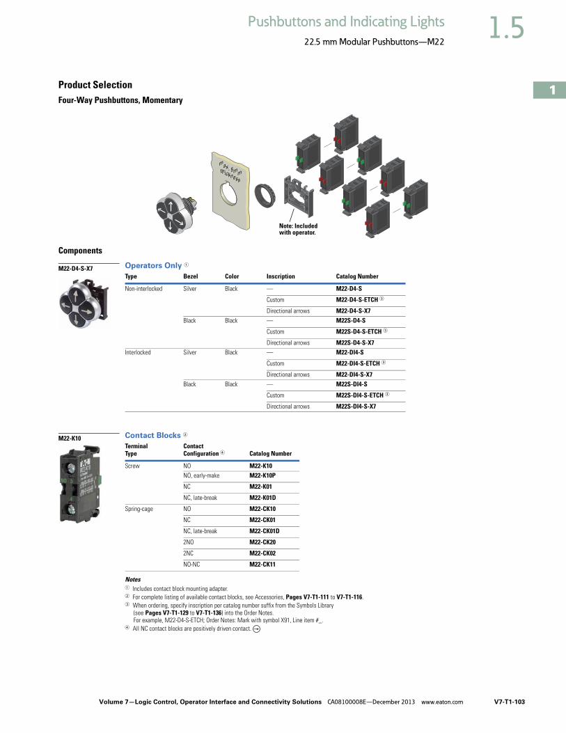
Volume 7—Logic Control, Operator Interface and Connectivity Solutions CA08100008E—December 2013 www.eaton.com V7-T1-103
1
1
1
1
1
1
1
1
1
1
1
1
1
1
1
1
1
1
1
1
1
1
1
1
1
1
1
1
1
1
1.5Pushbuttons and Indicating Lights
22.5 mm Modular Pushbuttons—M22
Product SelectionFour-Way Pushbuttons, Momentary
Components
Operators Only 1
Contact Blocks 2
Notes1 Includes contact block mounting adapter. 2 For complete listing of available contact blocks, see Accessories, Pages V7-T1-111 to V7-T1-116. 3 When ordering, specify inscription per catalog number suffix from the Symbols Library
(see Pages V7-T1-129 to V7-T1-136) into the Order Notes. For example, M22-D4-S-ETCH; Order Notes: Mark with symbol X91, Line item #_.
4 All NC contact blocks are positively driven contact.
Type Bezel Color Inscription Catalog Number
Non-interlocked Silver Black — M22-D4-S
Custom M22-D4-S-ETCH 3
Directional arrows M22-D4-S-X7Black Black — M22S-D4-S
Custom M22S-D4-S-ETCH 3
Directional arrows M22S-D4-S-X7Interlocked Silver Black — M22-DI4-S
Custom M22-DI4-S-ETCH 3
Directional arrows M22-DI4-S-X7Black Black — M22S-DI4-S
Custom M22S-DI4-S-ETCH 3
Directional arrows M22S-DI4-S-X7
TerminalType
Contact Configuration 4 Catalog Number
Screw NO M22-K10NO, early-make M22-K10P
NC M22-K01
NC, late-break M22-K01D
Spring-cage NO M22-CK10
NC M22-CK01
NC, late-break M22-CK01D
2NO M22-CK20
2NC M22-CK02
NO-NC M22-CK11
max. 5mmthickness
Note: Included with operator.
M22-D4-S-X7
M22-K10

V7-T1-104 Volume 7—Logic Control, Operator Interface and Connectivity Solutions CA08100008E—December 2013 www.eaton.com
1
1
1
1
1
1
1
1
1
1
1
1
1
1
1
1
1
1
1
1
1
1
1
1
1
1
1
1
1
1
1.5 Pushbuttons and Indicating Lights
22.5 mm Modular Pushbuttons—M22
JoysticksProduct DescriptionEaton’s M22 joystick line comes in a wide variety of options. From vertical and horizontal two-position switches to the maintained four-position, these operators fit a variety of applications. An additional option, two switch points, allows for eight isolated circuits to be actuated individually on a single operator.
Features● Available in four-position
and two-position● Two switch point option
allows for two contacts in each direction (up to eight total contacts in one operator)
● Capable of communicating via ASi protocol with ASi adapter modules
Protection Type● IP66
Product SelectionJoysticks
Components
Operators 1
Note1 Includes contact block mounting adapter.
Number of DirectionsSwitching Position
Silver BezelCatalog Number
Black BezelCatalog Number
Metal BezelCatalog Number
Two-position horizontal Momentary M22-WJ2H M22S-WJ2H M22M-WJ2H
Two switch points M22-WJ2H-2P M22S-WJ2H-2P M22M-WJ2H-2P
Two-position horizontal Maintained M22-WRJ2H M22S-WRJ2H M22M-WRJ2H
Two-position vertical Momentary M22-WJ2V M22S-WJ2V M22M-WJ2V
Two switch points M22-WJ2V-2P M22S-WJ2V-2P M22M-WJ2V-2P
Two-position vertical Maintained M22-WRJ2V M22S-WRJ2V M22M-WRJ2V
Four-position Momentary M22-WJ4 M22S-WJ4 M22M-WJ4
Two switch points M22-WJ4-2P M22S-WJ4-2P M22M-WJ4-2P
Four-position Maintained M22-WRJ4 M22S-WRJ4 M22M-WRJ4
M22-WJ2H
M22M-WJ2H

Volume 7—Logic Control, Operator Interface and Connectivity Solutions CA08100008E—December 2013 www.eaton.com V7-T1-105
1
1
1
1
1
1
1
1
1
1
1
1
1
1
1
1
1
1
1
1
1
1
1
1
1
1
1
1
1
1
1.5Pushbuttons and Indicating Lights
22.5 mm Modular Pushbuttons—M22
Joysticks
Contact Blocks 12
Notes1 Includes contact block mounting adapter. 2 For complete listing of available contact blocks, see Accessories,
Pages V7-T1-111 to V7-T1-116. 3 All NC contact blocks are positively driven contact.
Joystick with Double Contact
The joystick allows the control of up to four directions of movement on machines. Different variants of the joystick have two/four-positions and other variants have two settings for each position. This allows, for example, two-speed settings for each direction. For this application, a standard normally open contact and an early-make contact are fitted in series. Momentary contact and latching contact versions are available.
max. 5mmthickness
Note: Included with operator.
TerminalType
Contact Configuration 3 Catalog Number
Screw NO M22-K10NO, early-make M22-K10PNC M22-K01NC, late-break M22-K01D
Spring-cage NO M22-CK10NC M22-CK01NC, late-break M22-CK01D2NO M22-CK202NC M22-CK02NO-NC M22-CK11
M22-K10
0
1
01
2

V7-T1-106 Volume 7—Logic Control, Operator Interface and Connectivity Solutions CA08100008E—December 2013 www.eaton.com
1
1
1
1
1
1
1
1
1
1
1
1
1
1
1
1
1
1
1
1
1
1
1
1
1
1
1
1
1
1
1.5 Pushbuttons and Indicating Lights
22.5 mm Modular Pushbuttons—M22
PotentiometersProduct DescriptionEaton’s M22 potentiometers allow for a ready to use operator in a conveniently sized package. M22 potentiometers include the resistive element, instead of just a knob, and a built in legend surrounding the knob. The slim design, with integrated contacts and the range of resistances available, allows for a quick install.
Features● Scale markings on the knob allows the operator to be used
without an additional legend plate● Oversized knob option available● Slim design allows for space saving and simple wiring and
installation
Protection Type● IP66● NEMA 4X, 13
Product SelectionPotentiometers
Complete Devices
Acoustic DevicesProduct DescriptionEaton’s M22 acoustic devices are a simple and aesthetic way to add a buzzer or indicator to any application. Fitting in the same 22 mm hole, these devices can be ordered in continuous or pulsed tone and with or without the IP40 enclosure.
Features● Continuous or pulsed tone available● 83dB/10 cm decibel rating● Slim design allows for space saving and simple wiring and
installation
Protection Type● IP40● NEMA 12
Product SelectionAcoustic Devices
Complete Devices
Buzzers
BezelResistanceRk Catalog Number
Silver 1 M22-R1K4.7 M22-R4K710 M22-R10K47 M22-R47K100 M22-R100K470 M22-R470K
Black 1 M22S-R1K4.7 M22S-R4K710 M22S-R10K47 M22S-R47K100 M22S-R100K470 M22S-R470K
Metal 1 M22M-R1K4.7 M22M-R4K710 M22M-R10K47 M22M-R47K100 M22M-R100K470 M22M-R470K
Oversized Knob
Silver 1 M22-R1K-RH4.7 M22-R4K7-RH10 M22-R10K-RH47 M22-R47K-RH100 M22-R100K-RH470 M22-R470K-RH
Black 1 M22S-R1K-RH4.7 M22S-R4K7-RH10 M22S-R10K-RH47 M22S-R47K-RH100 M22S-R100K-RH470 M22S-R470K-RH
Metal 1 M22M-R1K-RH4.7 M22M-R4K7-RH10 M22M-R10K-RH47 M22M-R47K-RH100 M22M-R100K-RH470 M22M-R470K-RH
M22-R10K
M22M-R10K
DescriptionDecibel Rating Catalog Number
Indicator with buzzer, black continuous tone, 18–30 Vac/Vdc
83 dB/10 cm
M22-AMC-XAM
Indicator with buzzer,black pulsed tone,18–30 Vac/Vdc
83 dB/10 cm
M22-AMC-XAMP
DescriptionDecibel Rating Catalog Number
Indicator without buzzer, black
83 dB/10 cm
M22-AMC
Buzzer only, continuous tone, 18–30 Vac/Vdc
83 dB/10 cm
M22-XAM
Buzzer only, pulsed tone, 18–30 Vac/Vdc
83 dB/10 cm
M22-XAMP
M22-AMC-XAM
M22-XAM
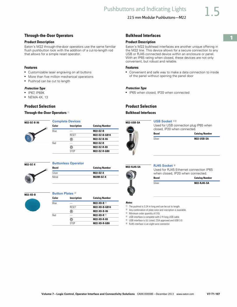
Volume 7—Logic Control, Operator Interface and Connectivity Solutions CA08100008E—December 2013 www.eaton.com V7-T1-107
1
1
1
1
1
1
1
1
1
1
1
1
1
1
1
1
1
1
1
1
1
1
1
1
1
1
1
1
1
1
1.5Pushbuttons and Indicating Lights
22.5 mm Modular Pushbuttons—M22
Through-the-Door OperatorsProduct DescriptionEaton’s M22 through-the-door operators use the same familiar flush pushbutton look with the addition of a cut-to-length rod that allows for a simple reset operator.
Features● Customizable laser engraving on all buttons● More than five million mechanical operations● Pushrod can be cut to length
Protection Type● IP67, IP69K● NEMA 4X, 13
Product SelectionThrough-the-Door Operators 1
Complete Devices
Buttonless Operator
Button Plates 2
Bulkhead InterfacesProduct DescriptionEaton’s M22 bulkhead interfaces are another unique offering in the M22 line. This device allows for a secure connection to any USB or RJ45 connected device within an enclosure or panel. With an IP65 rating when closed, these devices are not only convenient, but robust and reliable.
Features● Convenient and safe way to make a data connection to inside
of the panel without opening the panel door
Protection Type● IP65 when closed, IP20 when connected
Product SelectionBulkhead Interfaces
USB Socket 45
Used for USB connection plug IP65 when closed, IP20 when connected.
RJ45 Socket 6
Used for RJ45 Ethernet connection IP65 when closed, IP20 when connected.
Notes1 The pushrod is 3.24 in long and can be cut to length.2 Any combination of plate color and inscription is available.3 Minimum order quantity of (10).4 USB interface is complete with 2-ft-long USB cable.5 USB interface is UL Listed, CSA approved and USB 3.0.6 RJ45 interface is an eight-wire connector.
Color Inscription Catalog Number
Blue — M22-DZ-BRESET M22-DZ-B-GB14
M22-DZ-B-X6Red — M22-DZ-R
M22-DZ-R-X0STOP M22-DZ-R-GB0
Bezel Catalog Number
Silver M22-DZ-XMetal M22M-DZ-X
Color Inscription Catalog Number
Blue — M22-XD-B 3
RESET M22-XD-B-GB14M22-XD-B-X6
Red — M22-XD-R 3
M22-XD-R-X0STOP M22-XD-R-GB0
M22-DZ-B-X6
M22-DZ-X
M22-XD-B
Bezel Catalog Number
Silver M22-USB-SA
Bezel Catalog Number
Silver M22-RJ45-SA
M22-USB-SA
M22-RJ45-SA

V7-T1-108 Volume 7—Logic Control, Operator Interface and Connectivity Solutions CA08100008E—December 2013 www.eaton.com
1
1
1
1
1
1
1
1
1
1
1
1
1
1
1
1
1
1
1
1
1
1
1
1
1
1
1
1
1
1
1.5 Pushbuttons and Indicating Lights
22.5 mm Modular Pushbuttons—M22
ASi Adapter ModulesProduct DescriptionEaton’s M22 ASi adapter modules add functionality to every operator in the M22 line. These devices can be connected to any operator that uses contact blocks or LED units. The simple snap-on design allows for a quick integration of an entire application of operators to a communicating network.
Features● Allows compatible operators to communicate on an ASi
network● Not only can the status of a contact block be read, but LEDs
can be illuminated by an ASi adapter● ASi adapters simply clip on to the back of the contact blocks
and LEDs● Insulation displacement connectors allow for installation of
adapters without any tools● Two integrated LEDs indicate status of communications
Protection Type● IP20
Product SelectionASi Adapter Modules
Complete Devices
Description Catalog Number
ASi adapter module M22-ASIASi adapter module for base mounting
M22-ASI-C
ASi adapter module for E-stop
M22-ASI-S
ASi adapter module for E-stop base mounting
M22-ASI-CS
M22-ASI

Volume 7—Logic Control, Operator Interface and Connectivity Solutions CA08100008E—December 2013 www.eaton.com V7-T1-109
1
1
1
1
1
1
1
1
1
1
1
1
1
1
1
1
1
1
1
1
1
1
1
1
1
1
1
1
1
1
1.5Pushbuttons and Indicating Lights
22.5 mm Modular Pushbuttons—M22
Palm Switches
Product DescriptionEaton’s M22 palm switches are an oversized button that mount directly to an enclosure base. This allows for a standalone button that can be mounted anywhere. The enclosure uses base-mounted contact blocks, which allows for quick wiring and mounting. The palm switches come in momentary or maintained versions. As with other M22 operators, the palm switches are available as complete devices, including the enclosure and contact blocks or as modular components.
Features● Oversized operator in black, red and yellow color options● Button integrated directly into an enclosure● Base mounting contact blocks allow for simple wiring and
installation● More than one million mechanical operations on momentary
and 100,000 on maintained operators
Protection Type● IP67, IP69K● NEMA 4X, 13
Catalog Number SelectionCatalog Number Selection is for illustrative purposes only and not to be used to create new catalog numbers.
Palm Switches, Type 4X/13 Enclosure
Product SelectionComplete Devices
Operator, Base and Contact Blocks 1
Notes1 For complete listing of available contact blocks, see Accessories,
Pages V7-T1-111 to V7-T1-116. 2 All NC contact blocks are positively driven contact.
ButtonColor
Contact BlockConfiguration 2 Catalog Number
Momentary
Black 1NO-1NC FAK-S-KC11-IRed 1NO-1NC FAK-R-KC11-IYellow 1NO-1NC FAK-Y-KC11-I
Maintained
Red NC FAK-R-V-KC01-IY2NC FAK-R-V-KC02-IY1NO-2NC FAK-R-V-KC12-IY1NO-1NC FAK-R-V-KC11-IY
Operator TypeFAK = Palm switch
Contact BlocksKC10 = NOKC01 = NC
CKC10 = NOCKC01 = NCOperator Color
S = BlackR = RedY = Yellow
Enclosure Top Color
I = GrayIY = Yellow
FAK – S – KC10 – I
FAK-S-KC11-I
FAK-R-V-KC01-IY

V7-T1-110 Volume 7—Logic Control, Operator Interface and Connectivity Solutions CA08100008E—December 2013 www.eaton.com
1
1
1
1
1
1
1
1
1
1
1
1
1
1
1
1
1
1
1
1
1
1
1
1
1
1
1
1
1
1
1.5 Pushbuttons and Indicating Lights
22.5 mm Modular Pushbuttons—M22
Components
Operators Only
Palm Switch Enclosure Base
Contact Blocks 1
Notes1 For complete listing of available contact blocks, see Accessories, Pages V7-T1-111 to V7-T1-116. 2 All NC contact blocks are positively driven contact.
Type Button Color Catalog Number
Momentary Black FAK-SRed FAK-RYellow FAK-Y
Maintained Red FAK-R-V-Y
Catalog Number
FAK-IU
TerminalType
Contact Configuration 2 Catalog Number
Screw NO M22-KC10NC M22-KC01
Spring-cage NO M22-CKC10NC M22-CKC01
FAK-S
FAK-IU
M22-KC10

Volume 7—Logic Control, Operator Interface and Connectivity Solutions CA08100008E—December 2013 www.eaton.com V7-T1-111
1
1
1
1
1
1
1
1
1
1
1
1
1
1
1
1
1
1
1
1
1
1
1
1
1
1
1
1
1
1
1.5Pushbuttons and Indicating Lights
22.5 mm Modular Pushbuttons—M22
AccessoriesButton Plates
Note1 Refer to the Symbols Library, (see Pages V7-T1-129 to V7-T1-136), for symbol image.
Color InscriptionCatalog NumberFlush Pushbutton
Catalog NumberExtended Pushbutton
Catalog NumberMushroom Head Button
Black — M22-XD-S M22-XDH-S M22-XDP-SWhite — M22-XD-W M22-XDH-W M22-XDP-WRed — M22-XD-R M22-XDH-R M22-XDP-RGreen — M22-XD-G M22-XDH-G M22-XDP-GYellow — M22-XD-Y M22-XDH-Y M22-XDP-YBlue — M22-XD-B M22-XDH-B —Black, white, red, green, yellow, blue — M22-XD-SWRGYB M22-XDH-SWRGYB —Black, red, green — M22-XD-SRG M22-XDH-SRG —Black Custom M22-XD-S-ETCH M22-XDH-S-ETCH M22-XDP-S-ETCHWhite Custom M22-XD-W-ETCH M22-XDH-W-ETCH M22-XDP-W-ETCHRed Custom M22-XD-R-ETCH M22-XDH-R-ETCH M22-XDP-R-ETCHGreen Custom M22-XD-G-ETCH M22-XDH-G-ETCH M22-XDP-G-ETCHYellow Custom M22-XD-Y-ETCH M22-XDH-Y-ETCH M22-XDP-Y-ETCHBlue Custom M22-XD-B-ETCH M22-XDH-B-ETCH —Black STOP M22-XD-S-GB0 M22-XDH-S-GB0 M22-XDP-S-GB0Red STOP M22-XD-R-GB0 M22-XDH-R-GB0 M22-XDP-R-GB0Black START M22-XD-S-GB1 M22-XDH-S-GB1 M22-XDP-S-GB1White START M22-XD-W-GB1 M22-XDH-W-GB1 —Green START M22-XD-G-GB1 M22-XDH-G-GB1 M22-XDP-G-GB1Black CLOSE M22-XD-S-GB2 M22-XDH-S-GB2 —Black UP M22-XD-S-GB3 M22-XDH-S-GB3 M22-XDP-S-GB3Black DOWN M22-XD-S-GB4 M22-XDH-S-GB4 M22-XDP-S-GB4Black OFF M22-XD-S-GB5 M22-XDH-S-GB5 M22-XDP-S-GB5Red OFF M22-XD-R-GB5 M22-XDH-R-GB5 M22-XDP-R-GB5Black ON M22-XD-S-GB6 M22-XDH-S-GB6 M22-XDP-S-GB6Green ON M22-XD-G-GB6 M22-XDH-G-GB6 M22-XDP-G-GB6Black TEST M22-XD-S-GB9 M22-XDH-S-GB9 —Blue RESET M22-XD-B-GB14 M22-XDH-B-GB14 —Black FORWARD M22-XD-S-GB15 M22-XDH-S-GB15 M22-XDP-S-GB15Black REVERSE M22-XD-S-GB16 M22-XDH-S-GB16 M22-XDP-S-GB16Black RAISE M22-XD-S-GB17 M22-XDH-S-GB17 —Black LOWER M22-XD-S-GB18 M22-XDH-S-GB18 —Black M22-XD-S-X0 M22-XDH-S-X0 M22-XDP-S-X0Red M22-XD-R-X0 M22-XDH-R-X0 M22-XDP-R-X0Green — — M22-XDP-G-X0Black M22-XD-S-X1 M22-XDH-S-X1 M22-XDP-S-X1White M22-XD-W-X1 M22-XDH-W-X1 —Green M22-XD-G-X1 M22-XDH-G-X1 M22-XDP-G-X1Black M22-XD-S-X2 M22-XDH-S-X2 —Green M22-XD-G-X2 M22-XDH-G-X2 —Black M22-XD-S-X4 M22-XDH-S-X4 M22-XDP-S-X4Black M22-XD-S-X5 M22-XDH-S-X5 M22-XDP-S-X5Blue M22-XD-B-X6 M22-XDH-B-X6 —Black M22-XD-S-X7 M22-XDH-S-X7 M22-XDP-S-X7Black M22-XD-S-X8 M22-XDH-S-X8 —Black See 1 below M22-XD-S-X9 M22-XDH-S-X9 —Black See 1 below M22-XD-S-X10 M22-XDH-S-X10 —Black See 1 below M22-XD-S-X11 M22-XDH-S-X11 —Black See 1 below M22-XD-S-X12 M22-XDH-S-X12 —Black See 1 below M22-XD-S-X13 M22-XDH-S-X13 —Black See 1 below M22-XD-S-X14 M22-XDH-S-X14 —Black See 1 below M22-XD-S-X15 M22-XDH-S-X15 —Black See 1 below M22-XD-S-X16 M22-XDH-S-X16 —Black See 1 below M22-XD-S-X17 M22-XDH-S-X17 —
M22-XDH-R
M22-XDP-G
M22-XD-S

V7-T1-112 Volume 7—Logic Control, Operator Interface and Connectivity Solutions CA08100008E—December 2013 www.eaton.com
1
1
1
1
1
1
1
1
1
1
1
1
1
1
1
1
1
1
1
1
1
1
1
1
1
1
1
1
1
1
1.5 Pushbuttons and Indicating Lights
22.5 mm Modular Pushbuttons—M22
Button Lenses
Mounting Adapters
Contact Blocks
Notes1 All NC contact blocks are positively driven contact. 2 Not stackable.
Color InscriptionCatalog NumberFlush
Catalog NumberExtended Color Inscription
Catalog NumberFlush
Catalog NumberExtended
White — M22-XDL-W M22-XDLH-W Blue Custom M22-XDL-B-ETCH M22-XDLH-B-ETCHRed — M22-XDL-R M22-XDLH-R Red STOP M22-XDL-R-GB0 M22-XDLH-R-GB0Green — M22-XDL-G M22-XDLH-G Green START M22-XDL-G-GB1 M22-XDLH-G-GB1Yellow — M22-XDL-Y M22-XDLH-Y Red OFF M22-XDL-R-GB5 M22-XDLH-R-GB5Blue — M22-XDL-B M22-XDLH-B Green ON M22-XDL-G-GB6 M22-XDLH-G-GB6White Custom M22-XDL-W-ETCH M22-XDLH-W-ETCH Blue RESET M22-XDL-B-GB14 M22-XDLH-B-GB14Red Custom M22-XDL-R-ETCH M22-XDLH-R-ETCH Red M22-XDL-R-X0 M22-XDLH-R-X0Green Custom M22-XDL-G-ETCH M22-XDLH-G-ETCH Green M22-XDL-G-X1 M22-XDLH-G-X1Yellow Custom M22-XDL-Y-ETCH M22-XDLH-Y-ETCH Blue M22-XDL-B-X6 M22-XDLH-B-X6
Description Catalog Number
Contact block mounting adapter M22-A
Contact block mounting adapter, four-position (for use with four-way pushbuttons, joysticks and four-position selector switchesonly).
M22-A4
Allows mounting of M22 pushbuttons to LS-Titan limit switch bodies (for the full LS-Titan catalog section, see PG08301004E).
M22-LS
Mounting Location Terminal Type
Contact Configuration 1
PackageQty. Catalog Number
Front Screw NO 1 M22-K10NO 25 M22-K10-B25NO 100 M22-K10-B100NO, early-make 1 M22-K10PNC 1 M22-K01NC 25 M22-K01-B25NC 100 M22-K01-B100NC, late-break 1 M22-K01DSMCB, NC 1 M22-K01SMC10SMCB, 2NC 1 M22-K02SMC10
Base NO 1 M22-KC10NO 25 M22-KC10-B25NO 100 M22-KC10-B100NC 1 M22-KC01NC 25 M22-KC01-B25NC 100 M22-KC01-B100SMCB, NC 1 M22-KC01SMC10SMCB, 2NC 1 M22-KC02SMC10
Front Spring-cage NO 1 M22-CK10NC 1 M22-CK01NC, late-break 1 M22-CK01D2NO 2 1 M22-CK202NC 2 1 M22-CK02NO-NC 2 1 M22-CK11
Base NO 1 M22-CKC10NC 1 M22-CKC01
M22-XDLH-W
M22-XDL-G
M22-A
M22-A4
M22-LS
M22-K10

Volume 7—Logic Control, Operator Interface and Connectivity Solutions CA08100008E—December 2013 www.eaton.com V7-T1-113
1
1
1
1
1
1
1
1
1
1
1
1
1
1
1
1
1
1
1
1
1
1
1
1
1
1
1
1
1
1
1.5Pushbuttons and Indicating Lights
22.5 mm Modular Pushbuttons—M22
Light Units
LED Resistor and Test Elements
Notes1 Resistor units to be used with 12–30V light units. 2 Refer to IL04716002E for use of resistor elements in series for higher DC voltage.
Terminal TypeMounting Location LED Color Light Unit Voltage Catalog Number
Screw Front White 12–30 Vac/Vdc M22-LED-WRed M22-LED-RGreen M22-LED-GBlue M22-LED-BWhite 85–264 Vac M22-LED230-WRed M22-LED230-RGreen M22-LED230-GBlue M22-LED230-BWhite 207–264 Vac M22-LED230H-WRed M22-LED230H-RGreen M22-LED230H-GBlue M22-LED230H-B
Base White 12–30 Vac/Vdc M22-LEDC-WRed M22-LEDC-RGreen M22-LEDC-GBlue M22-LEDC-BWhite 85–264 Vac M22-LEDC230-WRed M22-LEDC230-RGreen M22-LEDC230-GBlue M22-LEDC230-BWhite 207–264 Vac M22-LEDC230H-WRed M22-LEDC230H-RGreen M22-LEDC230H-GBlue M22-LEDC230H-B
Spring-cage Front White 12–30 Vac/Vdc M22-CLED-WRed M22-CLED-RGreen M22-CLED-GBlue M22-CLED-BWhite 85–264 Vac M22-CLED230-WRed M22-CLED230-RGreen M22-CLED230-GBlue M22-CLED230-B
Base White 12–30 Vac/Vdc M22-CLEDC-WRed M22-CLEDC-RGreen M22-CLEDC-GBlue M22-CLEDC-BWhite 85–264 Vac M22-CLEDC230-WRed M22-CLEDC230-RGreen M22-CLEDC230-GBlue M22-CLEDC230-B
Terminal TypeMounting Location
ElementType Voltage Catalog Number
Screw Front Resistor 12 42–60 Vac/Vdc M22-XLED60220 Vdc M22-XLED220
Test 12–240 Vac/Vdc M22-XLED-T85–264 Vac M22-XLED230-T
M22-LED-W
M22-XLED60

V7-T1-114 Volume 7—Logic Control, Operator Interface and Connectivity Solutions CA08100008E—December 2013 www.eaton.com
1
1
1
1
1
1
1
1
1
1
1
1
1
1
1
1
1
1
1
1
1
1
1
1
1
1
1
1
1
1
1.5 Pushbuttons and Indicating Lights
22.5 mm Modular Pushbuttons—M22
Legend Plate Holders and Inserts, Pushbuttons and Double Pushbuttons 2
Notes1 When ordering, specify inscription per catalog number suffix from the Symbols Library
(see Pages V7-T1-129 to V7-T1-136) into the Order Notes. For example, M22-XD-S-ETCH; Order Notes: Mark with symbol X91, Line item #_.
2 Legend plates are IP66 and NEMA 4X/13.
ExampleTo order a legend plate for a pushbutton with non-standard markings (FORWARD):
1. Select legend plate holder—M22S-ST-X.
2. Select legend plate insert—M22-XST-ETCH.
3. Select FORWARD from the Symbols Library, Pages V7-T1-129 to V7-T1-136, identified by GB15 suffix.
4. Indicate on the order form in the order notes—suffix GB15, line item # ___ .
Description Inscription Catalog Number
Legend plate holder, without legend plate insert, for pushbuttons
— M22S-ST-X
Legend plate holder, without legend plate insert,for double pushbuttons
— M22S-STDD-X
Legend plate insert — M22-XSTCustom M22-XST-ETCH 1
STOP M22-XST-GB0START M22-XST-GB1OFF M22-XST-GB5ON M22-XST-GB6RUN M22-XST-GB7FAULT M22-XST-GB8OFF ON M22-XST-GB10MAN. AUTO M22-XST-GB11MAN. O AUTO M22-XST-GB12HAND AUTO M22-XST-D11HAND O AUTO M22-XST-D121 M22-XST-X522 M22-XST-X53O I M22-XST-X88O - I M22-XST-X89I O II M22-XST-X93
M22S-ST-X
M22-XST-GB0

Volume 7—Logic Control, Operator Interface and Connectivity Solutions CA08100008E—December 2013 www.eaton.com V7-T1-115
1
1
1
1
1
1
1
1
1
1
1
1
1
1
1
1
1
1
1
1
1
1
1
1
1
1
1
1
1
1
1.5Pushbuttons and Indicating Lights
22.5 mm Modular Pushbuttons—M22
Legend Plates, Complete 2
Notes1 When ordering, specify inscription per catalog number suffix from the Symbols Library (see Pages V7-T1-129 to V7-T1-136) into the Order Notes.
For example, M22-XD-S-ETCH; Order Notes: Mark with symbol X91, Line item #_.2 Legend plates are IP66 and NEMA 4X/13.
Description Inscription Catalog Number
For use with pushbuttons and indicating lights
Legend plate holder with insert STOP M22S-ST-GB0START M22S-ST-GB1OFF M22S-ST-GB5ON M22S-ST-GB6RUN M22S-ST-GB7FAULT M22S-ST-GB81 M22S-ST-X522 M22S-ST-X53
Selector switches — OFF ON M22S-ST-GB10MAN. AUTO M22S-ST-GB11MAN. O AUTO M22S-ST-GB12HAND AUTO M22S-ST-D11HAND O AUTO M22S-ST-D12O I M22S-ST-X88O - I M22S-ST-X89I O II M22S-ST-X93
Emergency-stop operators Rectangular yellow legend plate — M22-XZKCustom M22-XZK-ETCH 1
EMERGENCY-STOP M22-XZK-GB99
Square yellow legend plate — M22-XYK— M22-XYK-ETCH 1
EMERGENCY-STOP four-language M22-XYK1EMERGENCY-STOP (top and bottom) M22-XYK5
Round yellow legend plate, 90 mm — M22-XAKCustom M22-XAK-ETCH 1
EMERGENCY-STOP four-language M22-XAK1EMERGENCY-STOP (top and bottom) M22-XAK5
Round yellow legend plate, 60 mm — M22-XBKCustom M22-XBK-ETCH 1
EMERGENCY-STOP four-language M22-XBK1EMERGENCY-STOP (top and bottom) M22-XBK5
Four-way pushbutton, joystick and four-position selector switches
Silver square legend plate — M22-XCKCustom M22-XCK-ETCH 1
Four directional arrows M22-XCK10-1-0-2-0-3-0-4 M22-XCK2Two directional arrows M22-XCK3
M22S-ST-GB0
M22-XZK
M22-XBK1
M22-XCK1
M22-XYK

V7-T1-116 Volume 7—Logic Control, Operator Interface and Connectivity Solutions CA08100008E—December 2013 www.eaton.com
1
1
1
1
1
1
1
1
1
1
1
1
1
1
1
1
1
1
1
1
1
1
1
1
1
1
1
1
1
1
1.5 Pushbuttons and Indicating Lights
22.5 mm Modular Pushbuttons—M22
Surface Mounting Enclosures 1
Flush Mounting Plates, Aluminum
Shrouds, Plastic
Selector Switch Accessories
Notes1 Requires use of base mounted contact blocks.2 Plunger needed to actuate center-mounted contact blocks. Used for non-illuminated
three-position selector switches only.3 Enables a keyed selector switch to be set to user-selected key withdraw position.
Description Catalog Number
Yellow top, black base foremergency-stop operators
M22-IY1-PG
One-element enclosure M22-I1-PGTwo-element enclosure M22-I2-PGThree-element enclosure M22-I3-PGFour-element enclosure M22-I4-PGSix-element enclosure M22-I6-PGM20 connecting screw M22-XIM20 cord grip V-M20
Finish Rating Catalog Number
One Hole
Yellow paint for emergency-stop operators
— M22-EY1
Gray anodized IP65 M22-E1Two Holes
Gray anodized IP65 M22-E2Three Holes
Gray anodized IP65 M22-E3Four Holes
Gray anodized IP65 M22-E4Five Holes
Gray anodized IP65 M22-E5Six Holes
Anodized IP40 M22-E6
Description Rating Catalog Number
One-element IP55 M22-H1Two-element IP55 M22-H2Three-element IP55 M22-H3Four-element IP40 M22-H4Five-element IP40 M22-H5Six-element IP40 M22-H6Mounting plate — M22-XE5Plaster keys for flush mounting
— M22-UPE
M22-IY1-PG
M22-IY-PG
M22-EY1
M22-H1
Description Catalog Number
Plunger bridge 2 M22-XW
Key cover M22-XWS
Key withdraw adapter 3 M22-XC-R
Coding adapter M22-XC-Y
Guard ring M22-XGWK
M22-XC-Y
M22-XWS
M22-XC-R
M22-XW
M22-XGWK

Volume 7—Logic Control, Operator Interface and Connectivity Solutions CA08100008E—December 2013 www.eaton.com V7-T1-117
1
1
1
1
1
1
1
1
1
1
1
1
1
1
1
1
1
1
1
1
1
1
1
1
1
1
1
1
1
1
1.5Pushbuttons and Indicating Lights
22.5 mm Modular Pushbuttons—M22
Emergency Stop Operator Accessories
Blanking Plugs
Mounting Accessories
Protective Diaphragm
Dust Covers
Kits
Description Voltage Catalog Number
Yellow guard ring — M22-XGPV
Gray guard ring — M22G-XGPV
Rectangular guard — M22-MGTA
Sealing shroud — M22-PL-PV
Illuminated ring 24 Vac/Vdc M22-XPV60-Y-24120 Vac M22-XPV60-Y-120230 Vac M22-XPV60-Y-230
Color Catalog Number
Gray M22-BBlack M22S-B
M22-XGPV
M22G-XGPV
M22-PL-PV
M22-XPV60-Y-120
M22-MGTA
M22-B
Description Catalog Number
Telescopic clip with top-hat rail M22-TCTelescopic clip M22-TATelescopic clip extension M22-TCV
DIN rail mounting adapter M22-IVS
Mounting ring M22-GR
Mounting ring tool M22-MS
Adapter ring set for 30 mm holes
M22S-R30
For Use with … Catalog Number
Flush pushbuttons and indicating lights
M22-T-D
Double pushbuttons M22-T-DD
Description Catalog Number
Contact block dust cover M22-XKDPOperator dust cover, max three contact blocks
M22-ADC
Operator dust cover, max four contact blocks
M22-ADC4
Description Catalog Number
Includes one each: M22-XW, M22-XC-R, M22-XC-Y, M22S-B, M22-A, M22-XD-SWRGYB
M22-KT1
M22-TC and M22-TA
M22-IVS
M22-GR
M22-MS
M22S-R30
M22-T-D andM22-T-DD
M22-ADC4

V7-T1-118 Volume 7—Logic Control, Operator Interface and Connectivity Solutions CA08100008E—December 2013 www.eaton.com
1
1
1
1
1
1
1
1
1
1
1
1
1
1
1
1
1
1
1
1
1
1
1
1
1
1
1
1
1
1
1.5 Pushbuttons and Indicating Lights
22.5 mm Modular Pushbuttons—M22
Coding Adapter GuideSelector Switches
Two-Position Selector Switch
Three-Position Selector Switch
Two-Position Key-Operated Selector Switch
Three-Position Key-Operated Selector Switch
Top (B) Bottom (A) Catalog Number Function
M22(S)-W(L)(K) Momentary
M22(S)-WR(L)(K) Maintained
Top (B) Bottom (A) Catalog NumberFunctionLeft Right
M22(S)-W(L)(K)3 Momentary Momentary
M22(S)-WR(L)(K)3 Maintained Maintained
M22(S)-WR(L)(K)3-1 Maintained Momentary
M22(S)-WR(L)(K)3-2 Momentary Maintained
Top (B) Bottom (A) Catalog NumberCenterKey Withdraw
RightFunction Key Withdraw
M22(S)-WS Yes Momentary No
M22(S)-WRS Yes Maintained Yes
M22(S)-WRS-A1 Yes Maintained No
Top (B) Bottom (A) Catalog NumberLeftFunction Key Withdraw
CenterKey Withdraw
RightFunction Key Withdraw
M22(S)-WS3 Momentary No Yes Momentary No
M22(S)-WRS3 Maintained Yes Yes Maintained Yes
M22(S)-WRS3-A1 Maintained No Yes Maintained No
M22(S)-WRS3-A2 Maintained Yes Yes Maintained No
M22(S)-WRS3-A3 Maintained No Yes Maintained Yes
M22(S)-WRS3-A4 Maintained Yes Yes Momentary No
M22(S)-WRS3-A5 Maintained No Yes Momentary No
M22(S)-WRS3-A6 Momentary No Yes Maintained Yes
M22(S)-WRS3-A7 Momentary No Yes Maintained No
Top (B)
Bottom (A)
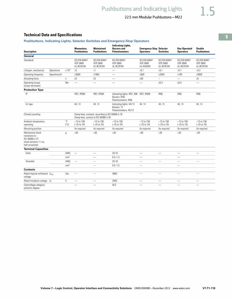
Volume 7—Logic Control, Operator Interface and Connectivity Solutions CA08100008E—December 2013 www.eaton.com V7-T1-119
1
1
1
1
1
1
1
1
1
1
1
1
1
1
1
1
1
1
1
1
1
1
1
1
1
1
1
1
1
1
1.5Pushbuttons and Indicating Lights
22.5 mm Modular Pushbuttons—M22
Technical Data and Specifications Pushbuttons, Indicating Lights, Selector Switches and Emergency-Stop Operators
DescriptionMomentary Pushbuttons
Maintained Pushbuttons
Indicating Lights, Buzzers and Potentiometers
Emergency-Stop Operators
SelectorSwitches
Key-Operated Operators
DoublePushbuttons
General
Standards IEC/EN 60947VDE 0660UL #E29184
IEC/EN 60947VDE 0660UL #E29184
IEC/EN 60947VDE 0660UL #E29184
IEC/EN 60947VDE 0660UL #340491
IEC/EN 60947VDE 0660UL #E29184
IEC/EN 60947VDE 0660UL #E29184
IEC/EN 60947VDE 0660UL #E29184
Lifespan, mechanical Operations x 106 >5 >1 — >0.1 >0.1 >0.1 >0.2
Operating frequency Operations/h >3600 >1800 — >600 >2000 >100 >3600
Actuating force n >5 >5 — >50 – — >5
Operating torque (screw terminals)
Nm — — — — >0.3 >0.5 —
Protection Type
IP IP67, IP69K IP67, IP69K Indicating lights: IP67, 69KBuzzers: IP40Potentiometers: IP66
IP67, IP69K IP66 IP66 IP66
UL type 4X, 13 4X, 13 Indicating lights: 4X/13Buzzers: 12Potentiometers: 4X/13
4X, 13 4X, 13 4X, 13 4X, 13
Climatic proofing Damp heat, constant, according to IEC 60068-2-78Damp heat, cyclical to IEC 60068-2-30
Ambient temperature, operating
°F(°C)
–13 to 158 (–25 to 70)
–13 to 158 (–25 to 70)
–13 to 158 (–25 to 70)
–13 to 158 (–25 to 70)
–13 to 158 (–25 to 70)
–13 to 158 (–25 to 70)
–13 to 158 (–25 to 70)
Mounting position As required As required As required As required As required As required As required
Mechanical shock resistance to IEC 60068-2-27 shock duration 11 ms, half-sinusoidal
g >30 >30 >30 >50 >30 >30 >30
Terminal Capacities
Solid AWG — — 20-16 — — — —
mm2 — 0.5–1.5 — —
Stranded AWG — — 20-16 — — — —
mm2 — 0.5–1.5 — —
Contacts
Rated impulse withstand voltage
Uimp Vac — — 4000 — — — —
Rated insulation voltage Ui V — — 2500 — — — —
Overvoltage category/pollution degree
— — III/3 — — — —
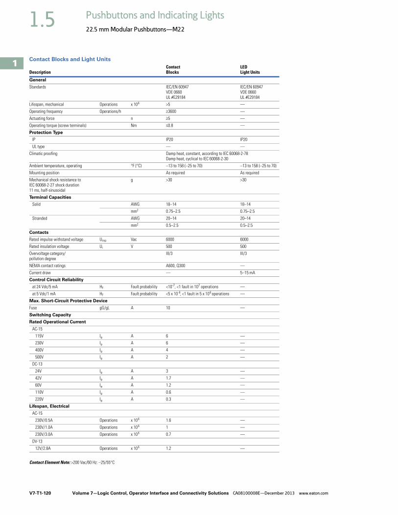
V7-T1-120 Volume 7—Logic Control, Operator Interface and Connectivity Solutions CA08100008E—December 2013 www.eaton.com
1
1
1
1
1
1
1
1
1
1
1
1
1
1
1
1
1
1
1
1
1
1
1
1
1
1
1
1
1
1
1.5 Pushbuttons and Indicating Lights
22.5 mm Modular Pushbuttons—M22
Contact Blocks and Light Units
DescriptionContactBlocks
LEDLight Units
General
Standards IEC/EN 60947VDE 0660UL #E29184
IEC/EN 60947VDE 0660UL #E29184
Lifespan, mechanical Operations x 106 >5 —
Operating frequency Operations/h >3600 —
Actuating force n >5 —
Operating torque (screw terminals) Nm <0.8 —
Protection Type
IP IP20 IP20
UL type — —
Climatic proofing Damp heat, constant, according to IEC 60068-2-78Damp heat, cyclical to IEC 60068-2-30
Ambient temperature, operating °F (°C) –13 to 158 (–25 to 70) –13 to 158 (–25 to 70)
Mounting position As required As required
Mechanical shock resistance to IEC 60068-2-27 shock duration 11 ms, half-sinusoidal
g >30 >30
Terminal Capacities
Solid AWG 18–14 18–14
mm2 0.75–2.5 0.75–2.5
Stranded AWG 20–14 20–14
mm2 0.5–2.5 0.5–2.5
Contacts
Rated impulse withstand voltage Uimp Vac 6000 6000
Rated insulation voltage Ui V 500 500
Overvoltage category/pollution degree
III/3 III/3
NEMA contact ratings A600, Q300 —
Current draw — 5–15 mA
Control Circuit Reliability
at 24 Vdc/5 mA HF Fault probability <10-7, <1 fault in 107 operations —
at 5 Vdc/1 mA HF Fault probability <5 x 10⁻⁶, <1 fault in 5 x 10⁶ operations —
Max. Short-Circuit Protective Device
Fuse gG/gL A 10 —
Switching Capacity
Rated Operational Current
AC-15
115V Ie A 6 —
230V Ie A 6 —
400V Ie A 4 —
500V Ie A 2 —
DC-13
24V Ie A 3 —
42V Ie A 1.7 —
60V Ie A 1.2 —
110V Ie A 0.6 —
220V Ie A 0.3 —
Lifespan, Electrical
AC-15
230V/0.5A Operations x 106 1.6 —
230V/1.0A Operations x 106 1 —
230V/3.0A Operations x 106 0.7 —
DV-13
12V/2.8A Operations x 106 1.2 —
Contact Element Note: >200 Vac/60 Hz: –25/55°C

Volume 7—Logic Control, Operator Interface and Connectivity Solutions CA08100008E—December 2013 www.eaton.com V7-T1-121
1
1
1
1
1
1
1
1
1
1
1
1
1
1
1
1
1
1
1
1
1
1
1
1
1
1
1
1
1
1
1.5Pushbuttons and Indicating Lights
22.5 mm Modular Pushbuttons—M22
Palm Switches
ASi Adapter Modules
Description Momentary Maintained FAK-R-V-KC11-I
General
Standards IEC/EN 60947VDE 0660
IEC/EN 60947VDE 0660
IEC/EN 60947VDE 0660
Lifespan, mechanical Operations x 106 >1 >0.1 >0.1
Operating frequency Operations/h >3600 >600 >600
Actuating force n 20–40 40–60 15–25
Operating torque Nm — — —
Degree of protection, IEC/EN 60529 IP IP67, IP69K IP67, IP69K IP65
UL Type 4X, 13 4X, 13 4X, 13
Climatic proofing Damp heat, constant, to IEC 60068-2-78Damp heat, cyclic, to IEC 60068-2-30
Ambient temperature, operating °F (°C) –73 to 104 (–25 to 40) –73 to 104 (–25 to 40) –73 to 104 (–25 to 40)
Mounting position As required
Mechanical shock resistance to IEC 60068-2-27 shock duration 11 ms, half-sinusoidal
g >15 >15 >15
Description M22-ASI M22-ASI-C
General
Standards IEC/EN 60947,DIN EN 50295
IEC/EN 60947,DIN EN 50295
Radio interference suppression EN 55011, EN 55022
EN 55011, EN 55022
Limit value class — —
Protection type IP20 IP00
Climatic proofing Damp heat, constant, to IEC 60068-2-78, cyclical, to IEC 60068-2-30
Ambient temperature, operating °F (°C) –13 to 131 (–25 to 55) –13 to 131 (–25 to 55)
Shock resistance shock duration 11 ms g >30 >30
Vibration to IEC 60068-2-27 (amplitude 1 mm)
Hz — —
Dimensions mm — —
Weight kg — —
Mounting Front mounting Front mounting
Mounting position As required As required
Power Supply
Rated voltage to AS-interface specification
Vdc 26.5–31.6 26.5–31.6
Connection technique Yellow plug-in terminal as insulation piercing terminal
Two cables onboard
Power supply Completely from the AS-interface cable
Addressing Via connection to AS-interface cable
Total power consumption ofthe AS-interface
mA >40 >40
AS-interface — —
Rated operational current at full load mA — —
Rated operational current when idle (no I, O set)
mA — —
Status LEDs POWER AS-interface cable: green LED on the rear side of the element
ERROR AS-interface, AS-interface master failure: red LED on the rear side of the element
POWER AS-interface cable: green LED on the board
ERROR AS-interface, AS-interface master failure: red LED on the board

V7-T1-122 Volume 7—Logic Control, Operator Interface and Connectivity Solutions CA08100008E—December 2013 www.eaton.com
1
1
1
1
1
1
1
1
1
1
1
1
1
1
1
1
1
1
1
1
1
1
1
1
1
1
1
1
1
1
1.5 Pushbuttons and Indicating Lights
22.5 mm Modular Pushbuttons—M22
ASi-S Adapter Modules
Description M22-ASI-S M22-ASI-CS
Inputs
Inputs, protected against short-circuit
Number Two (normally 22V/5 mA) Two (normally 22V/5 mA)
Voltage range Vdc — —
Rated current per input mA — —
High signal level V — —
Low signal mA — —
Length of connecting cables cm — —
Outputs
Outputs, protected against short-circuit
Number One (normally 19V/8 mA) One (normally 19V/8 mA)
Voltage range Vdc — —
Max. Current Carrying Capacity
All outputs — —
S three external outputs — —
Length of connecting cables cm — —
Profile S-3.A.E S-3.A.E
Specification 2.1 2.1
Addresses Number 62 62
Emergency-Stop Circuits
Connection of the AS-interface line Yellow plug terminal with insulation piercing
Two cables on the circuit board
Power supply Complete from AS-interface, cable 26.5–31.6 Vdc
Complete from AS-interface, cable 26.5–31.6 Vdc
Fixing Front mounted Base mounted
Addressing Via AS-interface cable Via AS-interface cable
Max. total current A 45 mA 45 mA
Ambient temperature, operating °F (°C) –13 to 131 (–25 to 55) –13 to 131 (–25 to 55)
Shock resistance 30g/11 ms as per IEC 60068-2-27 30g/11 ms as per IEC 60068-2-27
Protection type IP20 IP00
Climatic proofing Damp heat, constant, to IEC 60068-2-78, cyclical, to IEC 60068-2-30
Damp heat, constant, to IEC 60068-2-78, cyclical, to IEC 60068-2-30
Mounting position As required As required
Standards EN 50178EN 50 295
EN 50178EN 50 295
Inputs Two-channel input (22V/5 mA) (moduled by code sequence) (two break contact sets M22-K01)
Two-channel input (22V/5 mA) (moduled by code sequence) (two break contact sets M22-K01)
Outputs One output, typically 19V/8 mA, short-circuit proof
One output, typically 19V/8 mA, short-circuit proof
Status Displays
Power, AS-interface cable Green LED on the back Green LED on the back
AS-interface error,AS-interface master failure
Red LED on the back Red LED on the back
Profile S-7.B.E S-7.B.E

Volume 7—Logic Control, Operator Interface and Connectivity Solutions CA08100008E—December 2013 www.eaton.com V7-T1-123
1
1
1
1
1
1
1
1
1
1
1
1
1
1
1
1
1
1
1
1
1
1
1
1
1
1
1
1
1
1
1.5Pushbuttons and Indicating Lights
22.5 mm Modular Pushbuttons—M22
DimensionsApproximate Dimensions in Inches (mm)
Operators and Indicating Lights
Pushbuttons Selector Switches Operators
Key-Operated Selector Switches
Indicating Light
0.75 (19)
M22 x 0.06 (1.5)
0.39 (10)
Ø 1
.17
(2
9.7
)
Ø 1
.16
(2
9.5
)
0.04 (1)–0.24 (6)
1.17 (29.7)
0.39 (10) 0.65 (16.4)
M22…-D-_ M22…-DH-_
M22-DG(L)-_ M22…-DD-_
Ø1.
17
(2
9.7
)
0.65 (16.5)0.52 (13.2)
2.1
5 (
54
.7)
M22-D, Base Mounted
>0.01 (0.3)
1.78 (45.3)
0.04 (1)
1.4
7 (
37.
2)
0.93 (23.7) 1.06 (26.9)
M22…-W-_ M22…-WL-_
1.88 (47.75)
Ø1.
17
(2
9.7
)
0.81 (20.6)
M22…-W(R)S-_
0.45 (11.5)
M22-L_

V7-T1-124 Volume 7—Logic Control, Operator Interface and Connectivity Solutions CA08100008E—December 2013 www.eaton.com
1
1
1
1
1
1
1
1
1
1
1
1
1
1
1
1
1
1
1
1
1
1
1
1
1
1
1
1
1
1
1.5 Pushbuttons and Indicating Lights
22.5 mm Modular Pushbuttons—M22
Approximate Dimensions in Inches (mm)
Illuminated Pushbuttons
Mushroom Head Pushbutton
Emergency-Stop Operators
Potentiometer
Contact Block Mounting Adapter
Front Mounted Centering Adapter
Front Mounted Indicating Light
Pushbutton, Complete Devices
0.39 (10) 0.65 (16.4)
M22…-DL-_ M22…-DLH_
M22…-DP-_
Ø1.
44
(3
6.5
)
0.93 (23.6)
2.96 (75.1)
1.89 (47.9)
1.5 (38)
1.3
8 (
35
)
M22-PV_M22S-PV_M22-PVL_M22-PVS_
1.15 (29.2) 1.3 (32.9)
M22(S)-R_
1.73 (44)
1.7
7 (
45
)
1.18 (30)
0.76 (19.3)
0.85 (21.5)
M22-A_ M22S-A…
1.18 (30) 0.7 (17.8)
0.8
4 (
21.
4)
M22-ZA
1.18 (30) 1.77 (45)1.
46
(3
7)
0.3
9 (
10
)
0.3
9 (
10
)
0.3
9 (
10
)
1.18 (30)
2.8 (71)
1.77 (45)
A
1 x M22-K_ 2 x M22-K_ 1 x M22-CK_ 2 x M22-CK_
A 1.46 (37.2) 1.46 (37.2) 1.54 (39.0) 1.54 (39.0)

Volume 7—Logic Control, Operator Interface and Connectivity Solutions CA08100008E—December 2013 www.eaton.com V7-T1-125
1
1
1
1
1
1
1
1
1
1
1
1
1
1
1
1
1
1
1
1
1
1
1
1
1
1
1
1
1
1
1.5Pushbuttons and Indicating Lights
22.5 mm Modular Pushbuttons—M22
Approximate Dimensions in Inches (mm)
DIN-Rail Mounting Adapter
Pushbuttons and Indicating Lights with M22-TC Telescopic Clip and M22-TVC Extension
Palm Switches
Front Mounted Mounting Plate
Base Mounted Surface Mounting Enclosure
0.88 (22.4)
2.23 (56.7) 0.12 (3.1)
1.39 (35.2)
0.18 (4.5 (M4))
2.1
5 (
54
.5)
2.5
4 (
64
.5)
M22-D...M22-L...M22-W...M22-P...
0.88 (22.4)
A B
F
GE
C
D
H
1 Top-hat rail to IEC/EN 60715.
A B C D E F G H
1.77(45)
2.36–3.94(60–100)
0.79(20)
0.79(20)
0.18(4.5)
0.39(10)
154(39)
0.39(10)
M22-D_M22-L_M22-W_M22-P_
M22-TC M22-TCV1
L-...
1.3
6 (
34
.5)
1.42 (36)
M5 x 20
2.56 (65)
1.5
7 (
40
)
0.7
1 (
18
)
3.9
8 (
101
)
Ø94
0.2
6 (
6.5
) – 0
.3 (
7.5
)
3.35 (85)
FAK_
1 3 x M20 lateral, 1 x M16 in bottom.1
1.42 (36)
0.12 (3)
0.1 (2.5)
4 x M4 x 16
2.2
(5
6)
e
a1
1.3 (33)
2.8
3 (
72
)
M22-E_
CatalogNumber a1 e
CatalogNumber a1 e
M22-E(Y) 1 2.83 (72) 2.21 (56) M22-E4 6.73 (171) 6.10 (155)M22-E2 4.13 (105) 3.50 (89) M22-E5 8.03 (204) 7.40 (188)M22-E3 5.43 (138) 4.80 (122) M22-E6 9.33 (237) 8.70 (221)
1
3.1
5 (
80
)
1.7
3 (
44
)
M20
a
b1.3 (33)
1.89 (48)
2.2
(5
6)
M20/M25
e M4
2.6
2 (
66
.5)
0.7
(17.
8)
M20 M20
M20
M22-I_
CatalogNumber
Mounting Locations a b e Cable Entries
M22-I(Y)1 1 2.83(72.0)
1.68(42.6)
2.30(58.5)
2 x M16 3 x M20 2 x M25
M22-I2 2 4.72(120.0)
3.37(85.6)
4.19(106.5)
2 x M20 3 x M20 2 x M25
M22-I3 3 6.02(153.0)
4.67(118.6)
5.49(139.5)
2 x M20 2 x M25 4 x M20
M22-I4 4 7.32(186.0)
5.97(151.6)
6.79(172.5)
2 x M20 2 x M25 4 x M20
M22-I6 6 9.92(252.0)
8.57(217.6)
9.39(238.5)
2 x M20 2 x M25 4 x M20

V7-T1-126 Volume 7—Logic Control, Operator Interface and Connectivity Solutions CA08100008E—December 2013 www.eaton.com
1
1
1
1
1
1
1
1
1
1
1
1
1
1
1
1
1
1
1
1
1
1
1
1
1
1
1
1
1
1
1.5 Pushbuttons and Indicating Lights
22.5 mm Modular Pushbuttons—M22
Approximate Dimensions in Inches (mm)
Covers
Connecting Screw
Shroud with Plaster Keys
Legend Plates
Mounting Hole with Lug Slot
USB Socket
a2
M20 M20 M20
2.3
2 (
59
)
3.74 (95)
M22-H_
Catalog Number a2 Cable Entry Style
M22-H1 1.65 (42) 3 x M20 One-pieceM22-H2 2.95 (75) 4 x M20M22-H3 4.25 (108) 4 x M20M22-H4 5.55 (141) 4 x M20 SplitM22-H5 6.85 (174) 5 x M20M22-HE6 8.15 (207) 6 x M20
0.04 (1)
M22-XI
1 Gasket.
1
a2 +1.65 (42)
a2 +1.26 (32)
0.1
6 (
4)
2.2
(5
6)
2.7
6 (
70
)
a2
M22-H...
M22-H...
M22-UPE
0.31 (8)
0.3
1 (
8)
1.02 (26)
e
e + 0.51 (13)
0.35 (9)
0.35 (9)
M22-UPE
2 Box for closing off when plastering.3 Plaster thickness less than 8 mm.4 Plaster thickness more than 8 mm
1
2 3
1.18 (30)
0.59 (15)
1.3
8 (
35
)
1.18 (30)
1.0
8 (
27.
5)
1.8
5 (
47
)
M22S-ST-_ M22S-STDD-X
0.13 (3.2)
0.88 (22.3)
0.9
5 (
24
.1)
0.04 (1)–0.24 (6)

Volume 7—Logic Control, Operator Interface and Connectivity Solutions CA08100008E—December 2013 www.eaton.com V7-T1-127
1
1
1
1
1
1
1
1
1
1
1
1
1
1
1
1
1
1
1
1
1
1
1
1
1
1
1
1
1
1
1.5Pushbuttons and Indicating Lights
22.5 mm Modular Pushbuttons—M22
Approximate Dimensions in Inches (mm)
Grid Dimension to IEC/EN 60947
Grid Dimension for Various Combinations
Pushbutton Diaphragm
Grid Dimension for M22-DD_
Grid Dimension for M22-DDL_
Emergency Stop Sealing Cover
1.18 (30)
1.9
7 (
50
)
A
B
Pushbutton diaphragm cannot be combined with label mount.
Catalog Number A > B >
M22(S)-_(IEC/EN 60947) 1.18 (30.0) 1.97 (50.0)RMQ-Titan min. 1.18 (30.0) 1.58 (40.0)M22-D_ + M22-T-D 1.30 (33.0) 1.58 (40.0)M22-D(R)P_ 1.50 (38.0) 1.58 (40.0)M22-PV_ 1.50 (38.0) 1.58 (40.0)M22-PV(L) + M22-PL-PV 1.89 (48.0) 2.20 (56.0)M22-PV(L)(S_) + M22-D_ 1.30 (33.0) 1.58 (40.0)M22-DDL_ 1.18 (30.0) 2.17 (55.0)M22-DDL_ + M22-T-DD 1.30 (33.0) 2.28 (58.0)M22-ST_ 1.18 (30.0) 1.97 (50.0)M22-STDD_ 1.18 (30.0) 2.95 (75.0)M22-CK_ 1.18 (30.0) 1.77 (45.0)M22-CLED_ 1.18 (30.0) 1.77 (45.0)M22-XAK_ 3.54 (90.0) 3.54 (90.0)M22-XZK_ 1.30 (33.0) 2.04 (52.0)M22-XBK_ 2.36 (60.0) 2.36 (60.0)M22-XYK_ 1.97 (50.0) 1.97 (50.0)M22-D4 2.17 (55.0) 2.17 (55.0)M22-WR…4 1.97 (50.0) 1.97 (50.0)M22-W…J4 1.97 (50.0) 1.97 (50.0)
1.18 (30)
2.9
5 (
75
)
2.4
8 (
63
)
b
1.7
3 (
44
)
b
2.2
8 (
58
)
a 1.18 (30)
Pushbutton Diaphragm M22-T-DD 1
1 Pushbutton diaphragm cannot be combined with label mount.
1.26 (32)
1.8
9 (
48
)
0.4
1 (
10
.4)
2.0
3 (
51.
6)
M22-PL-PV

V7-T1-128 Volume 7—Logic Control, Operator Interface and Connectivity Solutions CA08100008E—December 2013 www.eaton.com
1
1
1
1
1
1
1
1
1
1
1
1
1
1
1
1
1
1
1
1
1
1
1
1
1
1
1
1
1
1
1.5 Pushbuttons and Indicating Lights
22.5 mm Modular Pushbuttons—M22
Approximate Dimensions in Inches (mm)
Blanking Plugs
Pushbutton Diaphragm
Guard Ring
Key Cover
Emergency Stop Legend Plate
Joystick
Four-Way Pushbutton
1.16 (29.5)
M22…B-_
1.3 (33)
0.6
7 (
17
)
1.3 (33)
0.67 (17)
0.91 (23)
2.2
8 (
58
)
M22-T-D M22-T-D
Ø 1.42 (36)
0.9
8 (
25
)
3.07 (78)
2.68 (68)
R35 R41
1.97 (50)
M22-XGWK M22-XGPV
0.47 (12)
0.2 (5)
Ø 0.98 (25)
0.7
9 (
20
)
M22-XWS
3.54 (90)
d= 0.03 (0.8)
1.3 (33)
0.6
5 (
16
.5)
1.9
7 (
50
)
M22-XAK_ M22-X(Y)ZK_
0.13 (3.2)
0.49 (12.5)
Ø 2.36 (60)
Ø 0
.89
(22.
5)1.97 (50)
1.9
7 (
50
)
M22-XBK-_ M22-XYK-_
1.18 (30)
2.95 (75)
M22…W…J_
2.17 (55)
0.45 (11.5)
M22…-D…4-_

Volume 7—Logic Control, Operator Interface and Connectivity Solutions CA08100008E—December 2013 www.eaton.com V7-T1-129
1
1
1
1
1
1
1
1
1
1
1
1
1
1
1
1
1
1
1
1
1
1
1
1
1
1
1
1
1
1
1.5Pushbuttons and Indicating Lights
22.5 mm Modular Pushbuttons—M22
Symbols LibraryInstructions for Ordering Laser Inscriptions1. Identify part number to be inscribed.
2. Pick symbol from library and identify suffix code associated with the symbol.
3. Order part number already listed in the catalog with -ETCH suffix.
4. When placing an order by fax or Vistaline on the Web, reference order item number and indicate appropriate suffix code.
ExampleTo order a green flush button plate with the inscription AUTO HAND:
Order Catalog Number: M22-XD-G-ETCH (see Page V7-T1-55).
AUTO HAND inscription is found on Page V7-T1-133 in the Symbols Library, suffix code is X91.
In the order notes, reference item number and suffix X91.
Letter height 3 mm: max three lines, max. 12 characters per line.
Letter height 5 mm: max. two lines, max. eight characters per line.
Note: For symbols or text not found in the Symbols Library, please contact the Eaton Technical Resource Center at 1-877-ETN CARE (386-2273) or [email protected].

V7-T1-130 Volume 7—Logic Control, Operator Interface and Connectivity Solutions CA08100008E—December 2013 www.eaton.com
1
1
1
1
1
1
1
1
1
1
1
1
1
1
1
1
1
1
1
1
1
1
1
1
1
1
1
1
1
1
1.5 Pushbuttons and Indicating Lights
22.5 mm Modular Pushbuttons—M22
Letter Height Specifications: < five characters; letter height = 0.197 in (5 mm). > five characters; letter height = 0.118 in (3 mm).
Text—English
Text—German
InscriptionCatalog Number Suffix
GB0
GB1
GB2
GB3
GB4
GB5
GB6
GB7
GB8
GB9
GB10
GB11
GB12
GB14
GB15
GB16
GB17
Text Size: 3 mm—Max. eight characters in first line;10 characters in second line; eight characters in third line.
Text Size: 5 mm—Max. five characters per line.
InscriptionCatalog Number Suffix
GB18
GB19
GB20
GB21
GB22
GB23
GB24
GB25
GB26
GB27
GB32
GB62
GB63
GB64
GB65
GB66
GB99
InscriptionCatalog Number Suffix
D0
D1
D2
D3
D4
D5
D6
D7
D8
D9
D10
D11
D12
D13
D14
D15
D16
D17
D18
D19
D20
D21
D22
D23
D24
InscriptionCatalog Number Suffix
D25
D28
D29
D30
D31
D32
D33
D34
D35
D36
D37
D38
D39
D40
D41
D42
D43
D44
D72
D73
D74
D75
D99
D100

Volume 7—Logic Control, Operator Interface and Connectivity Solutions CA08100008E—December 2013 www.eaton.com V7-T1-131
1
1
1
1
1
1
1
1
1
1
1
1
1
1
1
1
1
1
1
1
1
1
1
1
1
1
1
1
1
1
1.5Pushbuttons and Indicating Lights
22.5 mm Modular Pushbuttons—M22
Letter Height Specifications: < five characters; letter height = 0.197 in (5 mm). > five characters; letter height = 0.118 in (3 mm).
Text—French
Text—Swedish
Symbols
InscriptionCatalog Number Suffix
F0
F1
F2
F3
F4
F5
F6
F7
F8
F9
F10
F11
F12
F14
F15
F16
F17
F18
F19
F20
F67
F68
F99
Text Size: 3 mm—Max. eight characters in first line;10 characters in second line; eight characters in third line.
Text Size: 5 mm—Max. five characters per line.
InscriptionCatalog Number Suffix
S0
S1
S2
S3
S4
S5
S6
S7
S8
S9
S10
S11
S12
S14
S15
S16
S17
S18
S19
S20
S21
S22
S23
S32
S45
S46
S99
InscriptionCatalog Number Suffix
X0
X1
X2
X3
X4
X5
X6
X7
X8
X9
X10
X11
X12
InscriptionCatalog Number Suffix
X13
X14
X15
X16
X17
X18
X19
X20
X21
X22
X23
X24
X25
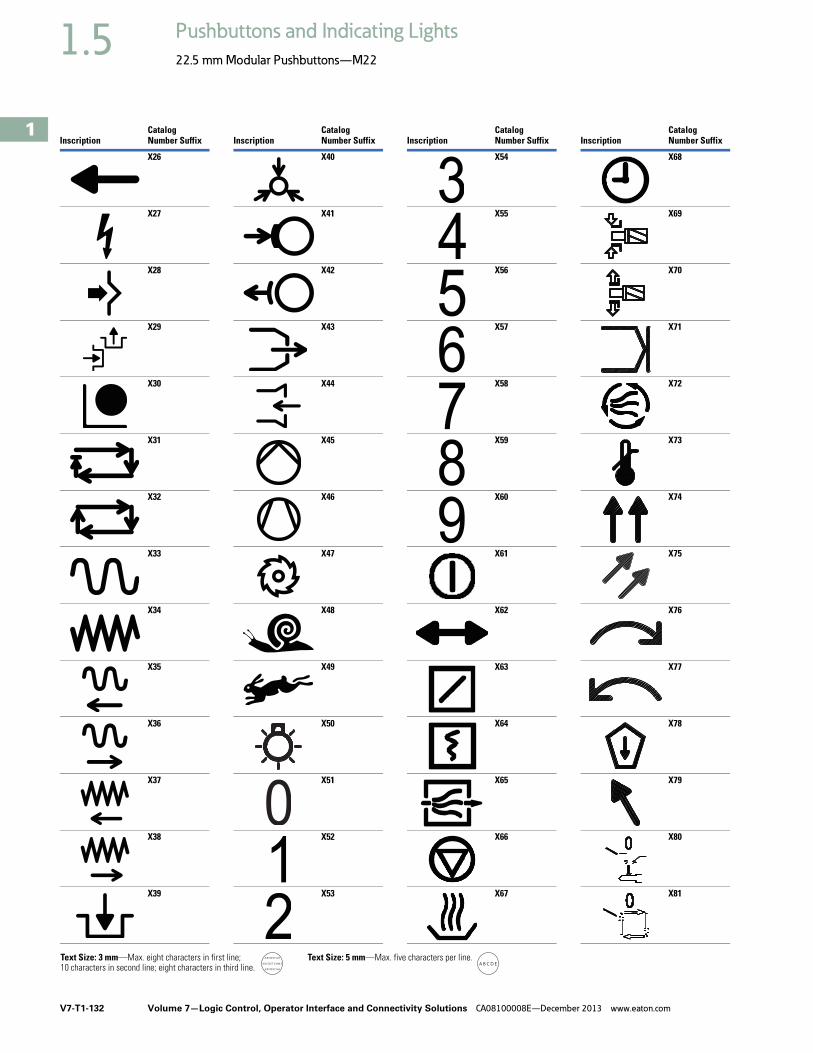
V7-T1-132 Volume 7—Logic Control, Operator Interface and Connectivity Solutions CA08100008E—December 2013 www.eaton.com
1
1
1
1
1
1
1
1
1
1
1
1
1
1
1
1
1
1
1
1
1
1
1
1
1
1
1
1
1
1
1.5 Pushbuttons and Indicating Lights
22.5 mm Modular Pushbuttons—M22
InscriptionCatalog Number Suffix
X26
X27
X28
X29
X30
X31
X32
X33
X34
X35
X36
X37
X38
X39
Text Size: 3 mm—Max. eight characters in first line;10 characters in second line; eight characters in third line.
Text Size: 5 mm—Max. five characters per line.
InscriptionCatalog Number Suffix
X40
X41
X42
X43
X44
X45
X46
X47
X48
X49
X50
X51
X52
X53
InscriptionCatalog Number Suffix
X54
X55
X56
X57
X58
X59
X60
X61
X62
X63
X64
X65
X66
X67
InscriptionCatalog Number Suffix
X68
X69
X70
X71
X72
X73
X74
X75
X76
X77
X78
X79
X80
X81
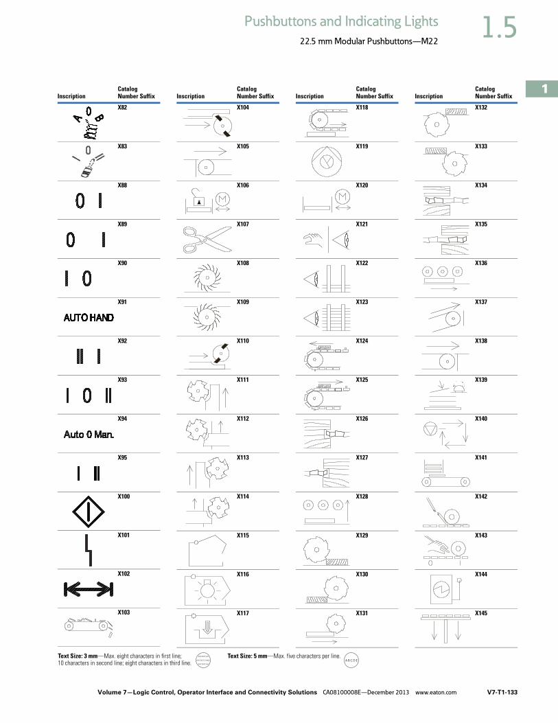
Volume 7—Logic Control, Operator Interface and Connectivity Solutions CA08100008E—December 2013 www.eaton.com V7-T1-133
1
1
1
1
1
1
1
1
1
1
1
1
1
1
1
1
1
1
1
1
1
1
1
1
1
1
1
1
1
1
1.5Pushbuttons and Indicating Lights
22.5 mm Modular Pushbuttons—M22
InscriptionCatalog Number Suffix
X82
X83
X88
X89
X90
X91
X92
X93
X94
X95
X100
X101
X102
X103
Text Size: 3 mm—Max. eight characters in first line;10 characters in second line; eight characters in third line.
Text Size: 5 mm—Max. five characters per line.
InscriptionCatalog Number Suffix
X104
X105
X106
X107
X108
X109
X110
X111
X112
X113
X114
X115
X116
X117
InscriptionCatalog Number Suffix
X118
X119
X120
X121
X122
X123
X124
X125
X126
X127
X128
X129
X130
X131
InscriptionCatalog Number Suffix
X132
X133
X134
X135
X136
X137
X138
X139
X140
X141
X142
X143
X144
X145

V7-T1-134 Volume 7—Logic Control, Operator Interface and Connectivity Solutions CA08100008E—December 2013 www.eaton.com
1
1
1
1
1
1
1
1
1
1
1
1
1
1
1
1
1
1
1
1
1
1
1
1
1
1
1
1
1
1
1.5 Pushbuttons and Indicating Lights
22.5 mm Modular Pushbuttons—M22
InscriptionCatalog Number Suffix
X146
X147
X148
X149
X150
X151
X152
X153
X154
X155
X156
X157
X158
X159
Text Size: 3 mm—Max. eight characters in first line;10 characters in second line; eight characters in third line.
Text Size: 5 mm—Max. five characters per line.
InscriptionCatalog Number Suffix
X160
X161
X162
X163
X164
X165
X166
X167
X168
X169
X170
X171
X172
X173
InscriptionCatalog Number Suffix
X174
X175
X176
X177
X178
X179
X180
X181
X182
X183
X184
X185
X186
X187
InscriptionCatalog Number Suffix
X188
X189
X190
X191
X192
X193
X194
X195
X196
X197
X198
X199
X200
X201

Volume 7—Logic Control, Operator Interface and Connectivity Solutions CA08100008E—December 2013 www.eaton.com V7-T1-135
1
1
1
1
1
1
1
1
1
1
1
1
1
1
1
1
1
1
1
1
1
1
1
1
1
1
1
1
1
1
1.5Pushbuttons and Indicating Lights
22.5 mm Modular Pushbuttons—M22
InscriptionCatalog Number Suffix
X202
X203
X204
X205
X206
X207
X208
X209
X210
X211
X212
X213
X214
X215
Text Size: 3 mm—Max. eight characters in first line;10 characters in second line; eight characters in third line.
Text Size: 5 mm—Max. five characters per line.
InscriptionCatalog Number Suffix
X216
X217
X218
X219
X220
X221
X222
X223
X224
X225
X226
X227
X228
X229
InscriptionCatalog Number Suffix
X230
X231
X232
X233
X234
X235
X236
X237
X238
X239
X240
X241
X242
X243
InscriptionCatalog Number Suffix
X244
X245
X246
X247
X248
X249
X250
X251
X252
X253
X254
X255
X256
X257

V7-T1-136 Volume 7—Logic Control, Operator Interface and Connectivity Solutions CA08100008E—December 2013 www.eaton.com
1
1
1
1
1
1
1
1
1
1
1
1
1
1
1
1
1
1
1
1
1
1
1
1
1
1
1
1
1
1
1.5 Pushbuttons and Indicating Lights
22.5 mm Modular Pushbuttons—M22
InscriptionCatalog Number Suffix
X258
X259
X260
X261
X262
X263
X264
Text Size: 3 mm—Max. eight characters in first line;10 characters in second line; eight characters in third line.
Text Size: 5 mm—Max. five characters per line.
InscriptionCatalog Number Suffix
X265
X266
X267
X268
X269
X270
X271
InscriptionCatalog Number Suffix
X272
X273
X274
X275
X276
X277
X278
InscriptionCatalog Number Suffix
X279
X280
X281
X282
X283
X284
X285

Volume 7—Logic Control, Operator Interface and Connectivity Solutions CA08100008E—December 2013 www.eaton.com V7-T1-137
1
1
1
1
1
1
1
1
1
1
1
1
1
1
1
1
1
1
1
1
1
1
1
1
1
1
1
1
1
1
1.6Pushbuttons and Indicating Lights
22.5 mm Compact Pushbuttons—C22
22.5 mm Compact Pushbuttons—C22 ContentsDescription Page
22.5 mm Compact Pushbuttons—C22Product Selection Guide . . . . . . . . . . . . . . . . . . V7-T1-139
Pushbuttons—Non-Illuminated andIlluminated . . . . . . . . . . . . . . . . . . . . . . . . . . . V7-T1-140
Indicating Lights . . . . . . . . . . . . . . . . . . . . . . . . V7-T1-149
Emergency Stops . . . . . . . . . . . . . . . . . . . . . . . V7-T1-151
Selector Switches . . . . . . . . . . . . . . . . . . . . . . . V7-T1-154
Technical Data and Specifications . . . . . . . . . . V7-T1-159
Dimensions . . . . . . . . . . . . . . . . . . . . . . . . . . . V7-T1-161
Product OverviewProduct DescriptionEaton’s C22 compact pushbutton line offers an industry leading array of functional, attractive, and ergonomically designed “all-in-one” illuminated and non-illuminated pushbuttons, selector switches, emergency stops and indicating lights. The complete illuminated line is only offered in LED light units to ensure high-quality brightness and up to 100,000 hours of LED illumination. C22 operators are available with either a silver or black bezel and share the exact same front of the panel look and feel as Eaton’s M22 line. The C22’s compact, “all-in-one” design with the contact block(s) and operators integral provides the user with a simple solution.
Wide Product Breadth● In addition to the standard
compact offering of indicating lights and pushbuttons, Eaton’s C22 offers keyed and non-keyed operators and emergency stops
● Hundreds of styles with standard laser etch markings with the ability to use custom M22 laser etched buttons in conjunction with C22 buttonless operators
LED Indicators● 100,000 hours of life
in high-vibration environments
● Lenses specifically designed for LED illumination
Rugged Design● Pushbuttons (momentary)
rated for 5 million mechanical operations and selector switches (non-keyed) rated for 1 million mechanical operations
● All components have IP65 rating, and some carry IP67 and IP69K for wash-down environment
Standards and CertificationsAll operators are IEC/EN 60947 VDE 0660, UL Listed, and CSA Certified.
All operators carry an IP65, IP66, IP67 or IP69K rating.
All products carry ratings of NEMA 1, 3R, 4X, 12 and 13

V7-T1-138 Volume 7—Logic Control, Operator Interface and Connectivity Solutions CA08100008E—December 2013 www.eaton.com
1
1
1
1
1
1
1
1
1
1
1
1
1
1
1
1
1
1
1
1
1
1
1
1
1
1
1
1
1
1
1.6 Pushbuttons and Indicating Lights
22.5 mm Compact Pushbuttons—C22
Features● Field convertible
maintained pushbuttons from maintained to momentary
● Field convertible selector switches from momentary to maintained operation and vice versa
● LED offering only for all illuminated operators
● Laser engraved pushbuttons and lenses
● Heavy-duty construction with a minimum of IP65 and UL NEMA® Type 4X/13 on front of panel operators. Many operators even carry IP67 and IP69K, for the toughest applications
● Silver or black colored nylon bezels
● Notched hole mounting with anti-rotation tab and central nut mounting on each operator
● Pushbuttons (momentary) rated for 5 million mechanical operations and selector switches (non-keyed) rated for 1 million mechanical operations
● Unique compact offerings, including keyed and non-keyed operators and emergency stops
Benefits● Compact, “all-in-one”
operator and contact block design simplifies product selection, inventory, and installation
● Field convertibility of pushbuttons and selector switches helps distributors and customers reduce inventory and increase functionality
● LED offering only for improved brightness quality and up to 100,000 hours of operation
● Plastic construction is corrosion resistant
● Operators are designed for rugged environments, ideal for wash-down applications (reference each operator’s IP ratings for ingress protection definition)
● Anti-rotation tab saves installation time and prevents operator rotation
● High mechanical and electrical life allows for use in tough and challenging applications
● Laser inscription capabilities allow for high quality, wear-resistant markings
● By having a compact design emergency stop, the C22 design eliminates the need for self-monitoring contact blocks

Volume 7—Logic Control, Operator Interface and Connectivity Solutions CA08100008E—December 2013 www.eaton.com V7-T1-139
1
1
1
1
1
1
1
1
1
1
1
1
1
1
1
1
1
1
1
1
1
1
1
1
1
1
1
1
1
1
1.6Pushbuttons and Indicating Lights
22.5 mm Compact Pushbuttons—C22
Product Selection GuidePushbuttons
Indicating Lights
Emergency Stops
Selector Switches
Description Non-illuminated, flush Non-illuminated, extended Illuminated, flush Illuminated, extended
Operator Momentary Maintained Momentary Maintained Momentary Maintained Momentary Maintained
Product Selection Page V7-T1-141 Page V7-T1-142 Page V7-T1-143 Page V7-T1-144 Page V7-T1-145 Page V7-T1-146 Page V7-T1-147 Page V7-T1-148
Description Indicating lights
Product Selection Page V7-T1-150
Description Twist release Keyed-release
Product Selection Page V7-T1-152 Page V7-T1-152
Description Non-illuminated, knob type Key-operated
Product Selection Page V7-T1-155 Page V7-T1-156

V7-T1-140 Volume 7—Logic Control, Operator Interface and Connectivity Solutions CA08100008E—December 2013 www.eaton.com
1
1
1
1
1
1
1
1
1
1
1
1
1
1
1
1
1
1
1
1
1
1
1
1
1
1
1
1
1
1
1.6 Pushbuttons and Indicating Lights
22.5 mm Compact Pushbuttons—C22
Pushbuttons—Non-Illuminated and Illuminated ContentsDescription Page
Pushbuttons—Non-Illuminated and Illuminated Non-Illuminated, Flush, Momentary . . . . . . . . V7-T1-141
Non-Illuminated, Flush, Maintained . . . . . . . . . V7-T1-142
Non-Illuminated, Extended, Momentary . . . . . V7-T1-143
Non-Illuminated, Extended, Maintained . . . . . . V7-T1-144
Illuminated, Flush, Momentary . . . . . . . . . . . . V7-T1-145
Illuminated, Flush, Maintained . . . . . . . . . . . . . V7-T1-146
Illuminated, Extended, Momentary . . . . . . . . . V7-T1-147
Illuminated, Extended, Maintained . . . . . . . . . V7-T1-148
Indicating Lights . . . . . . . . . . . . . . . . . . . . . . . . . . V7-T1-149
Emergency Stops . . . . . . . . . . . . . . . . . . . . . . . . . V7-T1-151
Selector Switches . . . . . . . . . . . . . . . . . . . . . . . . . V7-T1-154
Technical Data and Specifications . . . . . . . . . . . . . V7-T1-159
Dimensions . . . . . . . . . . . . . . . . . . . . . . . . . . . . . . V7-T1-161
Pushbuttons—Non-Illuminated and IlluminatedProduct DescriptionEaton’s C22 Compact Pushbuttons are a complete line of monoblock type pushbuttons with the contact blocks, mounting adapter, and operator all-in-one. The C22 pushbuttons offer the same look and feel as their modular counterpart, the M22. They also carry many of the same rugged ratings and options, such as laser etching, field convertibility, and LED technology.
Note: For additional accessories, please see Volume 7—Motor Controls, Logic and Connectivity, CA08100008E, Tab 37, section 37.4, 22.5 mm Modular Pushbuttons—M22.
Features● Field convertible
maintained pushbuttons from maintained to momentary
● LED offering only for improved brightness quality and up to 100,000 hours of operation
● Laser engraved pushbuttons and lenses
● Pushbuttons (momentary) rated for 5 million mechanical operations
Protection Type● IP67/IP69K● NEMA 4X, 13

Volume 7—Logic Control, Operator Interface and Connectivity Solutions CA08100008E—December 2013 www.eaton.com V7-T1-141
1
1
1
1
1
1
1
1
1
1
1
1
1
1
1
1
1
1
1
1
1
1
1
1
1
1
1
1
1
1
1.6Pushbuttons and Indicating Lights
22.5 mm Compact Pushbuttons—C22
Catalog Number SelectionCatalog Number Selection is for illustrative purposes only and not to be used to create new catalog numbers.
Non-Illuminated Pushbuttons
Product SelectionNon-Illuminated, Flush, Momentary
Non-Illuminated Pushbuttons, Flush, Momentary
Button Color
Button Etching
Contact Block Configuration
Silver BezelCatalog Number
Black BezelCatalog Number
Green — 1NO C22-D-G-K10 C22S-D-G-K10
— 2NO C22-D-G-K20 C22S-D-G-K20
— 1NO/1NC C22-D-G-K11 C22S-D-G-K11
X1 1NO C22-D-G-X1-K10 C22S-D-G-X1-K10
X1 2NO C22-D-G-X1-K20 C22S-D-G-X1-K20
X1 1NO/1NC C22-D-G-X1-K11 C22S-D-G-X1-K11
Red — 1NC C22-D-R-K01 C22S-D-R-K01
— 2NC C22-D-R-K02 C22S-D-R-K02
— 1NO/1NC C22-D-R-K11 C22S-D-R-K11
X0 1NC C22-D-R-X0-K01 C22S-D-R-X0-K01
X0 2NC C22-D-R-X0-K02 C22S-D-R-X0-K02
X0 1NO/1NC C22-D-R-X0-K11 C22S-D-R-X0-K11
Black — 1NC C22-D-S-K01 C22S-D-S-K01
— 2NC C22-D-S-K02 C22S-D-S-K02
— 1NO/1NC C22-D-S-K11 C22S-D-S-K11
X0 1NC C22-D-S-X0-K01 C22S-D-S-X0-K01
X0 2NC C22-D-S-X0-K02 C22S-D-S-X0-K02
X0 1NO/1NC C22-D-S-X0-K11 C22S-D-S-X0-K11
White — 1NO C22-D-W-K10 C22S-D-W-K10
— 2NO C22-D-W-K20 C22S-D-W-K20
— 1NO/1NC C22-D-W-K11 C22S-D-W-K11
X1 1NO C22-D-W-X1-K10 C22S-D-W-X1-K10
X1 2NO C22-D-W-X1-K20 C22S-D-W-X1-K20
X1 1NO/1NC C22-D-W-X1-K11 C22S-D-W-X1-K11
Buttonless — 1NO C22-D-X-K10 C22S-D-X-K10
— 2NO C22-D-X-K20 C22S-D-X-K20
— 1NC C22-D-X-K01 C22S-D-X-K01
— 2NC C22-D-X-K02 C22S-D-X-K02
— 1NO/1NC C22-D-X-K11 C22S-D-X-K11
C22 - D - G - X1 - K10
Bezel C22 = Silver
C22S = Black
Operator TypeD = Flush, momentary
DR = Flush, maintainedDH = Extended, momentary
DRH = Extended, maintained
Button Plate ColorG = GreenR = RedS = Black
W = WhiteX = Buttonless
Button EtchingX0 =X1 =
Contact BlocksK10 = 1NOK20 = 2NOK01 = 1NCK02 = 2NCK11 = 1NO/1NC
C22(S)-D-_

V7-T1-142 Volume 7—Logic Control, Operator Interface and Connectivity Solutions CA08100008E—December 2013 www.eaton.com
1
1
1
1
1
1
1
1
1
1
1
1
1
1
1
1
1
1
1
1
1
1
1
1
1
1
1
1
1
1
1.6 Pushbuttons and Indicating Lights
22.5 mm Compact Pushbuttons—C22
Non-Illuminated, Flush, Maintained
Non-Illuminated Pushbuttons, Flush, Maintained
Note: Maintained pushbuttons can be converted in the field to momentary operation by switching the locking ring, which is accessible through the side of the operator body.
Button Color
Button Etching
Contact Block Configuration
Silver BezelCatalog Number
Black BezelCatalog Number
Green — 1NO C22-DR-G-K10 C22S-DR-G-K10
— 2NO C22-DR-G-K20 C22S-DR-G-K20
— 1NO/1NC C22-DR-G-K11 C22S-DR-G-K11
X1 1NO C22-DR-G-X1-K10 C22S-DR-G-X1-K10
X1 2NO C22-DR-G-X1-K20 C22S-DR-G-X1-K20
X1 1NO/1NC C22-DR-G-X1-K11 C22S-DR-G-X1-K11
Red — 1NC C22-DR-R-K01 C22S-DR-R-K01
— 2NC C22-DR-R-K02 C22S-DR-R-K02
— 1NO/1NC C22-DR-R-K11 C22S-DR-R-K11
X0 1NC C22-DR-R-X0-K01 C22S-DR-R-X0-K01
X0 2NC C22-DR-R-X0-K02 C22S-DR-R-X0-K02
X0 1NO/1NC C22-DR-R-X0-K11 C22S-DR-R-X0-K11
Black — 1NC C22-DR-S-K01 C22S-DR-S-K01
— 2NC C22-DR-S-K02 C22S-DR-S-K02
— 1NO/1NC C22-DR-S-K11 C22S-DR-S-K11
X0 1NC C22-DR-S-X0-K01 C22S-DR-S-X0-K01
X0 2NC C22-DR-S-X0-K02 C22S-DR-S-X0-K02
X0 1NO/1NC C22-DR-S-X0-K11 C22S-DR-S-X0-K11
White — 1NO C22-DR-W-K10 C22S-DR-W-K10
— 2NO C22-DR-W-K20 C22S-DR-W-K20
— 1NO/1NC C22-DR-W-K11 C22S-DR-W-K11
X1 1NO C22-DR-W-X1-K10 C22S-DR-W-X1-K10
X1 2NO C22-DR-W-X1-K20 C22S-DR-W-X1-K20
X1 1NO/1NC C22-DR-W-X1-K11 C22S-DR-W-X1-K11
Buttonless — 1NO C22-DR-X-K10 C22S-DR-X-K10
— 2NO C22-DR-X-K20 C22S-DR-X-K20
— 1NC C22-DR-X-K01 C22S-DR-X-K01
— 2NC C22-DR-X-K02 C22S-DR-X-K02
— 1NO/1NC C22-DR-X-K11 C22S-DR-X-K11
C22(S)-DR-_

Volume 7—Logic Control, Operator Interface and Connectivity Solutions CA08100008E—December 2013 www.eaton.com V7-T1-143
1
1
1
1
1
1
1
1
1
1
1
1
1
1
1
1
1
1
1
1
1
1
1
1
1
1
1
1
1
1
1.6Pushbuttons and Indicating Lights
22.5 mm Compact Pushbuttons—C22
Non-Illuminated, Extended, Momentary
Non-Illuminated Pushbuttons, Extended, Momentary
Button Color
Button Etching
Contact Block Configuration
Silver BezelCatalog Number
Black BezelCatalog Number
Green — 1NO C22-DH-G-K10 C22S-DH-G-K10
— 2NO C22-DH-G-K20 C22S-DH-G-K20
— 1NO/1NC C22-DH-G-K11 C22S-DH-G-K11
X1 1NO C22-DH-G-X1-K10 C22S-DH-G-X1-K10
X1 2NO C22-DH-G-X1-K20 C22S-DH-G-X1-K20
X1 1NO/1NC C22-DH-G-X1-K11 C22S-DH-G-X1-K11
Red — 1NC C22-DH-R-K01 C22S-DH-R-K01
— 2NC C22-DH-R-K02 C22S-DH-R-K02
— 1NO/1NC C22-DH-R-K11 C22S-DH-R-K11
X0 1NC C22-DH-R-X0-K01 C22S-DH-R-X0-K01
X0 2NC C22-DH-R-X0-K02 C22S-DH-R-X0-K02
X0 1NO/1NC C22-DH-R-X0-K11 C22S-DH-R-X0-K11
Black — 1NC C22-DH-S-K01 C22S-DH-S-K01
— 2NC C22-DH-S-K02 C22S-DH-S-K02
— 1NO/1NC C22-DH-S-K11 C22S-DH-S-K11
X0 1NC C22-DH-S-X0-K01 C22S-DH-S-X0-K01
X0 2NC C22-DH-S-X0-K02 C22S-DH-S-X0-K02
X0 1NO/1NC C22-DH-S-X0-K11 C22S-DH-S-X0-K11
White — 1NO C22-DH-W-K10 C22S-DH-W-K10
— 2NO C22-DH-W-K20 C22S-DH-W-K20
— 1NO/1NC C22-DH-W-K11 C22S-DH-W-K11
X1 1NO C22-DH-W-X1-K10 C22S-DH-W-X1-K10
X1 2NO C22-DH-W-X1-K20 C22S-DH-W-X1-K20
X1 1NO/1NC C22-DH-W-X1-K11 C22S-DH-W-X1-K11
C22(S)-DH-_

V7-T1-144 Volume 7—Logic Control, Operator Interface and Connectivity Solutions CA08100008E—December 2013 www.eaton.com
1
1
1
1
1
1
1
1
1
1
1
1
1
1
1
1
1
1
1
1
1
1
1
1
1
1
1
1
1
1
1.6 Pushbuttons and Indicating Lights
22.5 mm Compact Pushbuttons—C22
Non-Illuminated, Extended, Maintained
Non-Illuminated Pushbuttons, Extended, Maintained
Note: Maintained pushbuttons can be converted in the field to momentary operation by switching the locking ring, which is accessible through the side of the operator body.
Button Color
Button Etching
Contact Block Configuration
Silver BezelCatalog Number
Black BezelCatalog Number
Green — 1NO C22-DRH-G-K10 C22S-DRH-G-K10
— 2NO C22-DRH-G-K20 C22S-DRH-G-K20
— 1NO/1NC C22-DRH-G-K11 C22S-DRH-G-K11
X1 1NO C22-DRH-G-X1-K10 C22S-DRH-G-X1-K10
X1 2NO C22-DRH-G-X1-K20 C22S-DRH-G-X1-K20
X1 1NO/1NC C22-DRH-G-X1-K11 C22S-DRH-G-X1-K11
Red — 1NC C22-DRH-R-K01 C22S-DRH-R-K01
— 2NC C22-DRH-R-K02 C22S-DRH-R-K02
— 1NO/1NC C22-DRH-R-K11 C22S-DRH-R-K11
X0 1NC C22-DRH-R-X0-K01 C22S-DRH-R-X0-K01
X0 2NC C22-DRH-R-X0-K02 C22S-DRH-R-X0-K02
X0 1NO/1NC C22-DRH-R-X0-K11 C22S-DRH-R-X0-K11
Black — 1NC C22-DRH-S-K01 C22S-DRH-S-K01
— 2NC C22-DRH-S-K02 C22S-DRH-S-K02
— 1NO/1NC C22-DRH-S-K11 C22S-DRH-S-K11
X0 1NC C22-DRH-S-X0-K01 C22S-DRH-S-X0-K01
X0 2NC C22-DRH-S-X0-K02 C22S-DRH-S-X0-K02
X0 1NO/1NC C22-DRH-S-X0-K11 C22S-DRH-S-X0-K11
White — 1NO C22-DRH-W-K10 C22S-DRH-W-K10
— 2NO C22-DRH-W-K20 C22S-DRH-W-K20
— 1NO/1NC C22-DRH-W-K11 C22S-DRH-W-K11
X1 1NO C22-DRH-W-X1-K10 C22S-DRH-W-X1-K10
X1 2NO C22-DRH-W-X1-K20 C22S-DRH-W-X1-K20
X1 1NO/1NC C22-DRH-W-X1-K11 C22S-DRH-W-X1-K11
C22(S)-DRH-_

Volume 7—Logic Control, Operator Interface and Connectivity Solutions CA08100008E—December 2013 www.eaton.com V7-T1-145
1
1
1
1
1
1
1
1
1
1
1
1
1
1
1
1
1
1
1
1
1
1
1
1
1
1
1
1
1
1
1.6Pushbuttons and Indicating Lights
22.5 mm Compact Pushbuttons—C22
Catalog Number SelectionCatalog Number Selection is for illustrative purposes only and not to be used to create new catalog numbers.
Illuminated Pushbuttons
Product SelectionIlluminated, Flush, Momentary
Illuminated Pushbuttons, Flush, Momentary
LED ColorButton Color Voltage
Button Etching
Contact Block Configuration
Silver BezelCatalog Number
Black BezelCatalog Number
Green Green 24 Vac/Vdc — 1NO C22-DL-G-K10-24 C22S-DL-G-K10-24
120 Vac — 1NO C22-DL-G-K10-120 C22S-DL-G-K10-120
230 Vac — 1NO C22-DL-G-K10-230 C22S-DL-G-K10-230
24 Vac/Vdc X1 1NO C22-DL-G-X1-K10-24 C22S-DL-G-X1-K10-24
120 Vac X1 1NO C22-DL-G-X1-K10-120 C22S-DL-G-X1-K10-120
230 Vac X1 1NO C22-DL-G-X1-K10-230 C22S-DL-G-X1-K10-230
Buttonless 24 Vac/Vdc — 1NO C22-DL-XG-K10-24 C22S-DL-XG-K10-24
120 Vac — 1NO C22-DL-XG-K10-120 C22S-DL-XG-K10-120
230 Vac — 1NO C22-DL-XG-K10-230 C22S-DL-XG-K10-230
Red Red 24 Vac/Vdc — 1NC C22-DL-R-K01-24 C22S-DL-R-K01-24
120 Vac — 1NC C22-DL-R-K01-120 C22S-DL-R-K01-120
230 Vac — 1NC C22-DL-R-K01-230 C22S-DL-R-K01-230
24 Vac/Vdc X0 1NC C22-DL-R-X0-K01-24 C22S-DL-R-X0-K01-24
120 Vac X0 1NC C22-DL-R-X0-K01-120 C22S-DL-R-X0-K01-120
230 Vac X0 1NC C22-DL-R-X0-K01-230 C22S-DL-R-X0-K01-230
Buttonless 24 Vac/Vdc — 1NC C22-DL-XR-K01-24 C22S-DL-XR-K01-24
120 Vac — 1NC C22-DL-XR-K01-120 C22S-DL-XR-K01-120
230 Vac — 1NC C22-DL-XR-K01-230 C22S-DL-XR-K01-230
White White 24 Vac/Vdc — 1NO C22-DL-W-K10-24 C22S-DL-W-K10-24
120 Vac — 1NO C22-DL-W-K10-120 C22S-DL-W-K10-120
230 Vac — 1NO C22-DL-W-K10-230 C22S-DL-W-K10-230
24 Vac/Vdc X1 1NO C22-DL-W-X1-K10-24 C22S-DL-W-X1-K10-24
120 Vac X1 1NO C22-DL-W-X1-K10-120 C22S-DL-W-X1-K10-120
230 Vac X1 1NO C22-DL-W-X1-K10-230 C22S-DL-W-X1-K10-230
Buttonless 24 Vac/Vdc — 1NO C22-DL-XW-K10-24 C22S-DL-XW-K10-24
120 Vac — 1NO C22-DL-XW-K10-120 C22S-DL-XW-K10-120
230 Vac — 1NO C22-DL-XW-K10-230 C22S-DL-XW-K10-230
Blue Blue 24 Vac/Vdc — 1NO C22-DL-B-K10-24 C22S-DL-B-K10-24
120 Vac — 1NO C22-DL-B-K10-120 C22S-DL-B-K10-120
230 Vac — 1NO C22-DL-B-K10-230 C22S-DL-B-K10-230
Buttonless 24 Vac/Vdc — 1NO C22-DL-XB-K10-24 C22S-DL-XB-K10-24
120 Vac — 1NO C22-DL-XB-K10-120 C22S-DL-XB-K10-120
230 Vac — 1NO C22-DL-XB-K10-230 C22S-DL-XB-K10-230
C22 - DL - G - X1 - K10 - 24
Bezel C22 = Silver
C22S = Black
Operator TypeDL = Illuminated, flush, momentary
DRL = Illuminated, flush, maintainedDLH = Illuminated, extended, momentary
DRLH = Illuminated, extended, maintained
Lens EtchingX0 =X1 =
Contact BlocksK10 = 1NOK01 = 1NC
LED Voltage24 = 24 Vac/Vdc
120 = 120 Vac230 = 230 Vac
LED/Lens ColorG = GreenR = Red
W = WhiteB = Blue
XG = Green without lensXR = Red without lens
XW = White without lensXB = Blue without lens
C22(S)-DL-_

V7-T1-146 Volume 7—Logic Control, Operator Interface and Connectivity Solutions CA08100008E—December 2013 www.eaton.com
1
1
1
1
1
1
1
1
1
1
1
1
1
1
1
1
1
1
1
1
1
1
1
1
1
1
1
1
1
1
1.6 Pushbuttons and Indicating Lights
22.5 mm Compact Pushbuttons—C22
Illuminated, Flush, Maintained
Illuminated Pushbuttons, Flush, Maintained
Note: Maintained pushbuttons can be converted in the field to momentary operation by switching the locking ring, which is accessible through the side of the operator body.
LED ColorButton Color Voltage
Contact Block Configuration
Silver BezelCatalog Number
Black BezelCatalog Number
Green Green 24 Vac/Vdc 1NO C22-DRL-G-K10-24 C22S-DRL-G-K10-24
120 Vac 1NO C22-DRL-G-K10-120 C22S-DRL-G-K10-120
230 Vac 1NO C22-DRL-G-K10-230 C22S-DRL-G-K10-230
Buttonless 24 Vac/Vdc 1NO C22-DRL-XG-K10-24 C22S-DRL-XG-K10-24
120 Vac 1NO C22-DRL-XG-K10-120 C22S-DRL-XG-K10-120
230 Vac 1NO C22-DRL-XG-K10-230 C22S-DRL-XG-K10-230
Red Red 24 Vac/Vdc 1NC C22-DRL-R-K01-24 C22S-DRL-R-K01-24
120 Vac 1NC C22-DRL-R-K01-120 C22S-DRL-R-K01-120
230 Vac 1NC C22-DRL-R-K01-230 C22S-DRL-R-K01-230
Buttonless 24 Vac/Vdc 1NC C22-DRL-XR-K01-24 C22S-DRL-XR-K01-24
120 Vac 1NC C22-DRL-XR-K01-120 C22S-DRL-XR-K01-120
230 Vac 1NC C22-DRL-XR-K01-230 C22S-DRL-XR-K01-230
White White 24 Vac/Vdc 1NO C22-DRL-W-K10-24 C22S-DRL-W-K10-24
120 Vac 1NO C22-DRL-W-K10-120 C22S-DRL-W-K10-120
230 Vac 1NO C22-DRL-W-K10-230 C22S-DRL-W-K10-230
Buttonless 24 Vac/Vdc 1NO C22-DRL-XW-K10-24 C22S-DRL-XW-K10-24
120 Vac 1NO C22-DRL-XW-K10-120 C22S-DRL-XW-K10-120
230 Vac 1NO C22-DRL-XW-K10-230 C22S-DRL-XW-K10-230
Blue Blue 24 Vac/Vdc 1NO C22-DRL-B-K10-24 C22S-DRL-B-K10-24
120 Vac 1NO C22-DRL-B-K10-120 C22S-DRL-B-K10-120
230 Vac 1NO C22-DRL-B-K10-230 C22S-DRL-B-K10-230
Buttonless 24 Vac/Vdc 1NO C22-DRL-XB-K10-24 C22S-DRL-XB-K10-24
120 Vac 1NO C22-DRL-XB-K10-120 C22S-DRL-XB-K10-120
230 Vac 1NO C22-DRL-XB-K10-230 C22S-DRL-XB-K10-230
C22(S)-DRL-_

Volume 7—Logic Control, Operator Interface and Connectivity Solutions CA08100008E—December 2013 www.eaton.com V7-T1-147
1
1
1
1
1
1
1
1
1
1
1
1
1
1
1
1
1
1
1
1
1
1
1
1
1
1
1
1
1
1
1.6Pushbuttons and Indicating Lights
22.5 mm Compact Pushbuttons—C22
Illuminated, Extended, Momentary
Illuminated Pushbuttons, Extended, Momentary
LED ColorButton Color Voltage
Button Etching
Contact Block Configuration
Silver BezelCatalog Number
Black BezelCatalog Number
Green Green 24 Vac/Vdc — 1NO C22-DLH-G-K10-24 C22S-DLH-G-K10-24
120 Vac — 1NO C22-DLH-G-K10-120 C22S-DLH-G-K10-120
230 Vac — 1NO C22-DLH-G-K10-230 C22S-DLH-G-K10-230
24 Vac/Vdc X1 1NO C22-DLH-G-X1-K10-24 C22S-DLH-G-X1-K10-24
120 Vac X1 1NO C22-DLH-G-X1-K10-120 C22S-DLH-G-X1-K10-12
230 Vac X1 1NO C22-DLH-G-X1-K10-230 C22S-DLH-G-X1-K10-23
Red Red 24 Vac/Vdc — 1NC C22-DLH-R-K01-24 C22S-DLH-R-K01-24
120 Vac — 1NC C22-DLH-R-K01-120 C22S-DLH-R-K01-120
230 Vac — 1NC C22-DLH-R-K01-230 C22S-DLH-R-K01-230
24 Vac/Vdc X0 1NC C22-DLH-R-X0-K01-24 C22S-DLH-R-X0-K01-24
120 Vac X0 1NC C22-DLH-R-X0-K01-120 C22S-DLH-R-X0-K01-12
230 Vac X0 1NC C22-DLH-R-X0-K01-230 C22S-DLH-R-X0-K01-23
White White 24 Vac/Vdc — 1NO C22-DLH-W-K10-24 C22S-DLH-W-K10-24
120 Vac — 1NO C22-DLH-W-K10-120 C22S-DLH-W-K10-120
230 Vac — 1NO C22-DLH-W-K10-230 C22S-DLH-W-K10-230
24 Vac/Vdc X1 1NO C22-DLH-W-X1-K10-24 C22S-DLH-W-X1-K10-24
120 Vac X1 1NO C22-DLH-W-X1-K10-120 C22S-DLH-W-X1-K10-12
230 Vac X1 1NO C22-DLH-W-X1-K10-230 C22S-DLH-W-X1-K10-23
Blue Blue 24 Vac/Vdc — 1NO C22-DLH-B-K10-24 C22S-DLH-B-K10-24
120 Vac — 1NO C22-DLH-B-K10-120 C22S-DLH-B-K10-120
230 Vac — 1NO C22-DLH-B-K10-230 C22S-DLH-B-K10-230
C22(S)-DLH-_

V7-T1-148 Volume 7—Logic Control, Operator Interface and Connectivity Solutions CA08100008E—December 2013 www.eaton.com
1
1
1
1
1
1
1
1
1
1
1
1
1
1
1
1
1
1
1
1
1
1
1
1
1
1
1
1
1
1
1.6 Pushbuttons and Indicating Lights
22.5 mm Compact Pushbuttons—C22
Illuminated, Extended, Maintained
Illuminated Pushbuttons, Flush, Maintained
Note: Maintained pushbuttons can be converted in the field to momentary operation by switching the locking ring, which is accessible through the side of the operator body.
LED ColorButton Color Voltage
Button Etching
Contact Block Configuration
Silver BezelCatalog Number
Black BezelCatalog Number
Green Green 24 Vac/Vdc — 1NO C22-DRLH-G-K10-24 C22S-DRLH-G-K10-24
120 Vac — 1NO C22-DRLH-G-K10-120 C22S-DRLH-G-K10-120
230 Vac — 1NO C22-DRLH-G-K10-230 C22S-DRLH-G-K10-230
24 Vac/Vdc X1 1NO C22-DRLH-G-X1-K10-24 C22S-DRLH-G-X1-K10-24
120 Vac X1 1NO C22-DRLH-G-X1-K10-120 C22S-DRLH-G-X1-K10-120
230 Vac X1 1NO C22-DRLH-G-X1-K10-230 C22S-DRLH-G-X1-K10-230
Red Red 24 Vac/Vdc — 1NC C22-DRLH-R-K01-24 C22S-DRLH-R-K01-24
120 Vac — 1NC C22-DRLH-R-K01-120 C22S-DRLH-R-K01-120
230 Vac — 1NC C22-DRLH-R-K01-230 C22S-DRLH-R-K01-230
24 Vac/Vdc X0 1NC C22-DRLH-R-X0-K01-24 C22S-DRLH-R-X0-K01-24
120 Vac X0 1NC C22-DRLH-R-X0-K01-120 C22S-DRLH-R-X0-K01-120
230 Vac X0 1NC C22-DRLH-R-X0-K01-230 C22S-DRLH-R-X0-K01-230
White White 24 Vac/Vdc — 1NO C22-DRLH-W-K10-24 C22S-DRLH-W-K10-24
120 Vac — 1NO C22-DRLH-W-K10-120 C22S-DRLH-W-K10-120
230 Vac — 1NO C22-DRLH-W-K10-230 C22S-DRLH-W-K10-230
24 Vac/Vdc X1 1NO C22-DRLH-W-X1-K10-24 C22S-DRLH-W-X1-K10-24
120 Vac X1 1NO C22-DRLH-W-X1-K10-120 C22S-DRLH-W-X1-K10-120
230 Vac X1 1NO C22-DRLH-W-X1-K10-230 C22S-DRLH-W-X1-K10-230
Blue Blue 24 Vac/Vdc — 1NO C22-DRLH-B-K10-24 C22S-DRLH-B-K10-24
120 Vac — 1NO C22-DRLH-B-K10-120 C22S-DRLH-B-K10-120
230 Vac — 1NO C22-DRLH-B-K10-230 C22S-DRLH-B-K10-230
C22(S)-DRLH-_

Volume 7—Logic Control, Operator Interface and Connectivity Solutions CA08100008E—December 2013 www.eaton.com V7-T1-149
1
1
1
1
1
1
1
1
1
1
1
1
1
1
1
1
1
1
1
1
1
1
1
1
1
1
1
1
1
1
1.6Pushbuttons and Indicating Lights
22.5 mm Compact Pushbuttons—C22
Indicating Lights ContentsDescription Page
Pushbuttons—Non-Illuminated andIlluminated . . . . . . . . . . . . . . . . . . . . . . . . . . . . . V7-T1-140
Indicating Lights Catalog Number Selection . . . . . . . . . . . . . . . . V7-T1-150
Product Selection . . . . . . . . . . . . . . . . . . . . . . . V7-T1-150
Emergency Stops . . . . . . . . . . . . . . . . . . . . . . . . . V7-T1-151
Selector Switches . . . . . . . . . . . . . . . . . . . . . . . . . V7-T1-154
Technical Data and Specifications . . . . . . . . . . . . . V7-T1-159
Dimensions . . . . . . . . . . . . . . . . . . . . . . . . . . . . . . V7-T1-161
Indicating LightsProduct DescriptionC22 indicating lights use a combination of a durable, bright LED unit and modern lenses designed specifically for this type of LED to create a bright and visible indicating light. As with the pushbuttons, the indicating light lenses can be laser etched, simply order without lens and order M22/C22 custom etched lenses to attach.
Note: For additional accessories, please see Volume 7—Motor Controls, Logic and Connectivity, CA08100008E, Tab 37, section 37.4, 22.5 mm Modular Pushbuttons—M22.
Features● LED offering only for
improved brightness quality and up to 100,000 hours of operation
● Lenses specifically designed for LED illumination
● Lenses capable of being laser etched for custom solutions that last
Protection Type● IP67/IP69K● NEMA 4X, 13
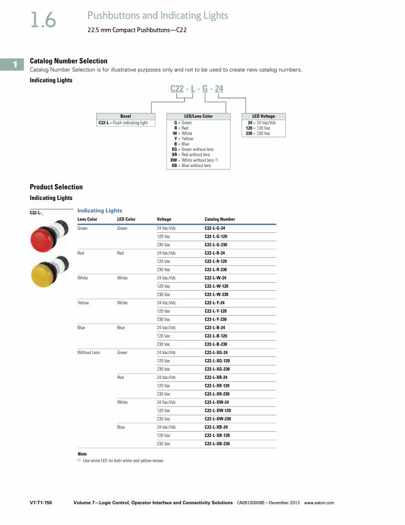
V7-T1-150 Volume 7—Logic Control, Operator Interface and Connectivity Solutions CA08100008E—December 2013 www.eaton.com
1
1
1
1
1
1
1
1
1
1
1
1
1
1
1
1
1
1
1
1
1
1
1
1
1
1
1
1
1
1
1.6 Pushbuttons and Indicating Lights
22.5 mm Compact Pushbuttons—C22
Catalog Number SelectionCatalog Number Selection is for illustrative purposes only and not to be used to create new catalog numbers.
Indicating Lights
Product SelectionIndicating Lights
Indicating Lights
Note1 Use white LED for both white and yellow lenses.
Lens Color LED Color Voltage Catalog Number
Green Green 24 Vac/Vdc C22-L-G-24
120 Vac C22-L-G-120
230 Vac C22-L-G-230
Red Red 24 Vac/Vdc C22-L-R-24
120 Vac C22-L-R-120
230 Vac C22-L-R-230
White White 24 Vac/Vdc C22-L-W-24
120 Vac C22-L-W-120
230 Vac C22-L-W-230
Yellow White 24 Vac/Vdc C22-L-Y-24
120 Vac C22-L-Y-120
230 Vac C22-L-Y-230
Blue Blue 24 Vac/Vdc C22-L-B-24
120 Vac C22-L-B-120
230 Vac C22-L-B-230
Without Lens Green 24 Vac/Vdc C22-L-XG-24
120 Vac C22-L-XG-120
230 Vac C22-L-XG-230
Red 24 Vac/Vdc C22-L-XR-24
120 Vac C22-L-XR-120
230 Vac C22-L-XR-230
White 24 Vac/Vdc C22-L-XW-24
120 Vac C22-L-XW-120
230 Vac C22-L-XW-230
Blue 24 Vac/Vdc C22-L-XB-24
120 Vac C22-L-XB-120
230 Vac C22-L-XB-230
C22 - L - G - 24
BezelC22-L = Flush indicating light
LED Voltage24 = 24 Vac/Vdc
120 = 120 Vac230 = 230 Vac
LED/Lens ColorG = GreenR = Red
W = WhiteY = YellowB = Blue
XG = Green without lensXR = Red without lens
XW = White without lens 1XB = Blue without lens
C22-L-_

Volume 7—Logic Control, Operator Interface and Connectivity Solutions CA08100008E—December 2013 www.eaton.com V7-T1-151
1
1
1
1
1
1
1
1
1
1
1
1
1
1
1
1
1
1
1
1
1
1
1
1
1
1
1
1
1
1
1.6Pushbuttons and Indicating Lights
22.5 mm Compact Pushbuttons—C22
Emergency Stops ContentsDescription Page
Pushbuttons—Non-Illuminated andIlluminated . . . . . . . . . . . . . . . . . . . . . . . . . . . . . V7-T1-140
Indicating Lights . . . . . . . . . . . . . . . . . . . . . . . . . . V7-T1-149
Emergency Stops Non-Illuminated, Twist-Release . . . . . . . . . . . . V7-T1-152
Non-Illuminated, Keyed-Release . . . . . . . . . . . . V7-T1-152
Selector Switches . . . . . . . . . . . . . . . . . . . . . . . . . V7-T1-154
Technical Data and Specifications . . . . . . . . . . . . . V7-T1-159
Dimensions . . . . . . . . . . . . . . . . . . . . . . . . . . . . . . V7-T1-161
Emergency StopsProduct DescriptionC22 emergency stops are a durable and reliable solution to a variety of e-stop applications. This compact e-stop, available as twist-to-release and keyed-release, is a simple product that eliminates the need for self-monitoring contact blocks, all while still meeting almost all of the industry safety standards.
Note: For additional accessories, please see Volume 7—Motor Controls, Logic and Connectivity, CA08100008E, Tab 37, section 37.4, 22.5 mm Modular Pushbuttons—M22.
Features● Available in both twist-
release and keyed-release with either 45 mm or 60 mm operators
Protection Type● Twist-Release
● IP67/IP69K
● Keyed-Release● IP66
● NEMA 4X, 13

V7-T1-152 Volume 7—Logic Control, Operator Interface and Connectivity Solutions CA08100008E—December 2013 www.eaton.com
1
1
1
1
1
1
1
1
1
1
1
1
1
1
1
1
1
1
1
1
1
1
1
1
1
1
1
1
1
1
1.6 Pushbuttons and Indicating Lights
22.5 mm Compact Pushbuttons—C22
Catalog Number SelectionCatalog Number Selection is for illustrative purposes only and not to be used to create new catalog numbers.
Emergency Stops
Product SelectionNon-Illuminated, Twist-Release
Non-Illuminated Emergency Stops, Twist-Release
Non-Illuminated, Keyed-Release
Non-Illuminated Emergency Stops, Keyed-Release
Release Method Operator SizeContact Block Configuration Catalog Number
Twist-release 45 mm 2NC C22-PVT45P-K02
1NO/1NC C22-PVT45P-K11
60 mm 2NC C22-PVT60P-K02
1NO/1NC C22-PVT60P-K11
Release Method Operator Size Key CodeContact Block Configuration Catalog Number
Keyed-release 45 mm MS1 2NC C22-PVS45P-MS1-K02
1NO/1NC C22-PVS45P-MS1-K11
MS2 2NC C22-PVS45P-MS2-K02
1NO/1NC C22-PVS45P-MS2-K11
MS3 2NC C22-PVS45P-MS3-K02
1NO/1NC C22-PVS45P-MS3-K11
MS4 2NC C22-PVS45P-MS4-K02
1NO/1NC C22-PVS45P-MS4-K11
MS5 2NC C22-PVS45P-MS5-K02
1NO/1NC C22-PVS45P-MS5-K11
MS6 2NC C22-PVS45P-MS6-K02
1NO/1NC C22-PVS45P-MS6-K11
MS7 2NC C22-PVS45P-MS7-K02
1NO/1NC C22-PVS45P-MS7-K11
MS8 2NC C22-PVS45P-MS8-K02
1NO/1NC C22-PVS45P-MS8-K11
Ronis 2NC C22-PVS45P-RS-K02
1NO/1NC C22-PVS45P-RS-K11
C22 - PVS45P - MS1 - K01
Operator Type PVT45P = Twist-release, 45 mmPVT60P = Twist-release, 60 mmPVS45P = Key-release, 45 mmPVS60P = Key-release, 60 mm
Key CodeMS1 = MS1MS2 = MS2MS3 = MS3MS4 = MS4MS5 = MS5MS6 = MS6MS7 = MS7MS8 = MS8
RS = Ronis-445
Contact Blocks K02 = 2NC K11 = 1NO/1NC
C22-PVT_
C22-PVS_
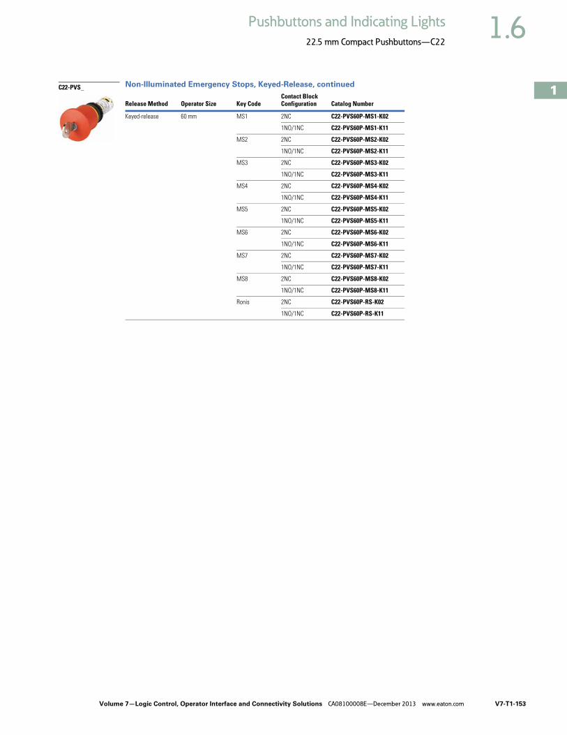
Volume 7—Logic Control, Operator Interface and Connectivity Solutions CA08100008E—December 2013 www.eaton.com V7-T1-153
1
1
1
1
1
1
1
1
1
1
1
1
1
1
1
1
1
1
1
1
1
1
1
1
1
1
1
1
1
1
1.6Pushbuttons and Indicating Lights
22.5 mm Compact Pushbuttons—C22
Non-Illuminated Emergency Stops, Keyed-Release, continued
Release Method Operator Size Key CodeContact Block Configuration Catalog Number
Keyed-release 60 mm MS1 2NC C22-PVS60P-MS1-K02
1NO/1NC C22-PVS60P-MS1-K11
MS2 2NC C22-PVS60P-MS2-K02
1NO/1NC C22-PVS60P-MS2-K11
MS3 2NC C22-PVS60P-MS3-K02
1NO/1NC C22-PVS60P-MS3-K11
MS4 2NC C22-PVS60P-MS4-K02
1NO/1NC C22-PVS60P-MS4-K11
MS5 2NC C22-PVS60P-MS5-K02
1NO/1NC C22-PVS60P-MS5-K11
MS6 2NC C22-PVS60P-MS6-K02
1NO/1NC C22-PVS60P-MS6-K11
MS7 2NC C22-PVS60P-MS7-K02
1NO/1NC C22-PVS60P-MS7-K11
MS8 2NC C22-PVS60P-MS8-K02
1NO/1NC C22-PVS60P-MS8-K11
Ronis 2NC C22-PVS60P-RS-K02
1NO/1NC C22-PVS60P-RS-K11
C22-PVS_

V7-T1-154 Volume 7—Logic Control, Operator Interface and Connectivity Solutions CA08100008E—December 2013 www.eaton.com
1
1
1
1
1
1
1
1
1
1
1
1
1
1
1
1
1
1
1
1
1
1
1
1
1
1
1
1
1
1
1.6 Pushbuttons and Indicating Lights
22.5 mm Compact Pushbuttons—C22
Selector Switches ContentsDescription Page
Pushbuttons—Non-Illuminated andIlluminated . . . . . . . . . . . . . . . . . . . . . . . . . . . . . V7-T1-140
Indicating Lights . . . . . . . . . . . . . . . . . . . . . . . . . . V7-T1-149
Emergency Stops . . . . . . . . . . . . . . . . . . . . . . . . . V7-T1-151
Selector Switches Non-Illuminated, Knob Type . . . . . . . . . . . . . . . V7-T1-155
Non-Illuminated, Key Operated . . . . . . . . . . . . V7-T1-156
Technical Data and Specifications . . . . . . . . . . . . . V7-T1-159
Dimensions . . . . . . . . . . . . . . . . . . . . . . . . . . . . . . V7-T1-161
Selector SwitchesProduct DescriptionWith over 20 variations of operation and 8 varieties of key codes, the C22 line offers a very complete line of selector switches.
Note: For additional accessories, please see Volume 7—Motor Controls, Logic and Connectivity, CA08100008E, Tab 37, section 37.4, 22.5 mm Modular Pushbuttons—M22.
Features● Selector switch (non-
keyed) rated for 1 million mechanical operations
● Momentary selector switches are field convertible from momentary to maintained
Protection Type● IP65● NEMA 4X, 13

Volume 7—Logic Control, Operator Interface and Connectivity Solutions CA08100008E—December 2013 www.eaton.com V7-T1-155
1
1
1
1
1
1
1
1
1
1
1
1
1
1
1
1
1
1
1
1
1
1
1
1
1
1
1
1
1
1
1.6Pushbuttons and Indicating Lights
22.5 mm Compact Pushbuttons—C22
Catalog Number SelectionCatalog Number Selection is for illustrative purposes only and not to be used to create new catalog numbers.
Selector Switches—Non-Keyed
Product SelectionNon-Illuminated, Knob Type
Non-Illuminated Selector Switches, Knob Type
Note: Momentary selector switches can be field converted to maintained.
TypeSwitching Position
Contact Block Configuration
Silver BezelCatalog Number
Black BezelCatalog Number
Two-position Momentary 1NO C22-WK-K10 C22S-WK-K10
2NO C22-WK-K20 C22S-WK-K20
1NC C22-WK-K01 C22S-WK-K01
2NC C22-WK-K02 C22S-WK-K02
1NO/1NC C22-WK-K11 C22S-WK-K11
Momentary 1NO C22-WKV-K10 C22S-WKV-K10
2NO C22-WKV-K20 C22S-WKV-K20
1NC C22-WKV-K01 C22S-WKV-K01
2NC C22-WKV-K02 C22S-WKV-K02
1NO/1NC C22-WKV-K11 C22S-WKV-K11
Maintained 1NO C22-WRK-K10 C22S-WRK-K10
2NO C22-WRK-K20 C22S-WRK-K20
1NC C22-WRK-K01 C22S-WRK-K01
2NC C22-WRK-K02 C22S-WRK-K02
1NO/1NC C22-WRK-K11 C22S-WRK-K11
Maintained 1NO C22-WRKV-K10 C22S-WRKV-K10
2NO C22-WRKV-K20 C22S-WRKV-K20
1NC C22-WRKV-K01 C22S-WRKV-K01
2NC C22-WRKV-K02 C22S-WRKV-K02
1NO/1NC C22-WRKV-K11 C22S-WRKV-K11
Three-position Momentary 2NO C22-WK3-K20 C22S-WK3-K20
2NC C22-WK3-K02 C22S-WK3-K02
1NO/1NC C22-WK3-K11 C22S-WK3-K11
Maintained 2NO C22-WRK3-K20 C22S-WRK3-K20
2NC C22-WRK3-K02 C22S-WRK3-K02
1NO/1NC C22-WRK3-K11 C22S-WRK3-K11
C22 - WK - K10
Bezel C22 = Silver
C22S = Black
Operator TypeWK = 2-position, momentary
WKV = 2-position, momentary, “V” positionWRK = 2-position, maintained
WRKV = 2-position, maintained, “V” positionWK3 = 3-position, momentary
WRK3 = 3-position, maintained
Contact BlocksK10 = 1NOK20 = 2NOK01 = 1NCK02 = 2NCK11 = 1NO/1NC
C22(S)-WK-_/C22(S)-WRK_
40°
60°
40°
60°
40°40°
60° 60°

V7-T1-156 Volume 7—Logic Control, Operator Interface and Connectivity Solutions CA08100008E—December 2013 www.eaton.com
1
1
1
1
1
1
1
1
1
1
1
1
1
1
1
1
1
1
1
1
1
1
1
1
1
1
1
1
1
1
1.6 Pushbuttons and Indicating Lights
22.5 mm Compact Pushbuttons—C22
Catalog Number SelectionCatalog Number Selection is for illustrative purposes only and not to be used to create new catalog numbers.
Selector Switches—Keyed
Non-Illuminated, Key Operated
Non-Illuminated Selector Switches, Key Operated
Note: Momentary selector switches can be field converted to maintained.
Position Type Key CodeContact Block Configuration
Silver BezelCatalog Number
Black BezelCatalog Number
Two-position Momentarykey removal left
MS1 1NO C22-WS-MS1-K10 C22S-WS-MS1-K10
2NO C22-WS-MS1-K20 C22S-WS-MS1-K20
1NC C22-WS-MS1-K01 C22S-WS-MS1-K01
2NC C22-WS-MS1-K02 C22S-WS-MS1-K02
1NO/1NC C22-WS-MS1-K11 C22S-WS-MS1-K11
MS2 1NO C22-WS-MS2-K10 C22S-WS-MS2-K10
2NO C22-WS-MS2-K20 C22S-WS-MS2-K20
1NC C22-WS-MS2-K01 C22S-WS-MS2-K01
2NC C22-WS-MS2-K02 C22S-WS-MS2-K02
1NO/1NC C22-WS-MS2-K11 C22S-WS-MS2-K11
MS3 1NO C22-WS-MS3-K10 C22S-WS-MS3-K10
2NO C22-WS-MS3-K20 C22S-WS-MS3-K20
1NC C22-WS-MS3-K01 C22S-WS-MS3-K01
2NC C22-WS-MS3-K02 C22S-WS-MS3-K02
1NO/1NC C22-WS-MS3-K11 C22S-WS-MS3-K11
MS4 1NO C22-WS-MS4-K10 C22S-WS-MS4-K10
2NO C22-WS-MS4-K20 C22S-WS-MS4-K20
1NC C22-WS-MS4-K01 C22S-WS-MS4-K01
2NC C22-WS-MS4-K02 C22S-WS-MS4-K02
1NO/1NC C22-WS-MS4-K11 C22S-WS-MS4-K11
MS5 1NO C22-WS-MS5-K10 C22S-WS-MS5-K10
2NO C22-WS-MS5-K20 C22S-WS-MS5-K20
1NC C22-WS-MS5-K01 C22S-WS-MS5-K01
2NC C22-WS-MS5-K02 C22S-WS-MS5-K02
1NO/1NC C22-WS-MS5-K11 C22S-WS-MS5-K11
C22 - WS - MS1 - A1 - K10
Bezel C22 = Silver
C22S = Black
Operator TypeWS = 2-position, momentaryWRS = 2-position, maintainedWRS-…-A1 = 2-position, maintained,
key removal leftWS3 = 3-position, momentaryWRS3 = 3-position, maintained
Contact BlocksK10 = 1NOK20 = 2NOK01 = 1NCK02 = 2NCK11 = 1NO/1NC
Key CodeMS1 = MS1MS2 = MS2MS3 = MS3MS4 = MS4MS5 = MS5MS6 = MS6MS7 = MS7MS8 = MS8
1
1
C22(S)-WS-MS_
40°
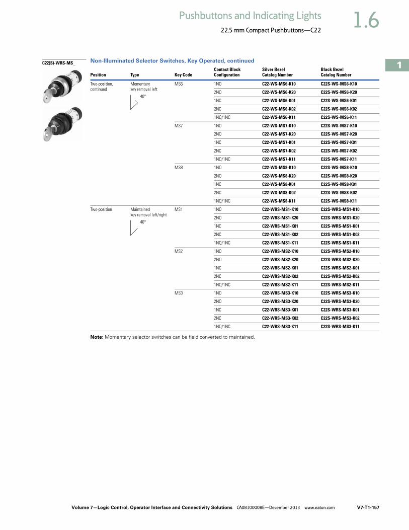
Volume 7—Logic Control, Operator Interface and Connectivity Solutions CA08100008E—December 2013 www.eaton.com V7-T1-157
1
1
1
1
1
1
1
1
1
1
1
1
1
1
1
1
1
1
1
1
1
1
1
1
1
1
1
1
1
1
1.6Pushbuttons and Indicating Lights
22.5 mm Compact Pushbuttons—C22
Non-Illuminated Selector Switches, Key Operated, continued
Note: Momentary selector switches can be field converted to maintained.
Position Type Key CodeContact Block Configuration
Silver BezelCatalog Number
Black BezelCatalog Number
Two-position, continued
Momentarykey removal left
MS6 1NO C22-WS-MS6-K10 C22S-WS-MS6-K10
2NO C22-WS-MS6-K20 C22S-WS-MS6-K20
1NC C22-WS-MS6-K01 C22S-WS-MS6-K01
2NC C22-WS-MS6-K02 C22S-WS-MS6-K02
1NO/1NC C22-WS-MS6-K11 C22S-WS-MS6-K11
MS7 1NO C22-WS-MS7-K10 C22S-WS-MS7-K10
2NO C22-WS-MS7-K20 C22S-WS-MS7-K20
1NC C22-WS-MS7-K01 C22S-WS-MS7-K01
2NC C22-WS-MS7-K02 C22S-WS-MS7-K02
1NO/1NC C22-WS-MS7-K11 C22S-WS-MS7-K11
MS8 1NO C22-WS-MS8-K10 C22S-WS-MS8-K10
2NO C22-WS-MS8-K20 C22S-WS-MS8-K20
1NC C22-WS-MS8-K01 C22S-WS-MS8-K01
2NC C22-WS-MS8-K02 C22S-WS-MS8-K02
1NO/1NC C22-WS-MS8-K11 C22S-WS-MS8-K11
Two-position Maintainedkey removal left/right
MS1 1NO C22-WRS-MS1-K10 C22S-WRS-MS1-K10
2NO C22-WRS-MS1-K20 C22S-WRS-MS1-K20
1NC C22-WRS-MS1-K01 C22S-WRS-MS1-K01
2NC C22-WRS-MS1-K02 C22S-WRS-MS1-K02
1NO/1NC C22-WRS-MS1-K11 C22S-WRS-MS1-K11
MS2 1NO C22-WRS-MS2-K10 C22S-WRS-MS2-K10
2NO C22-WRS-MS2-K20 C22S-WRS-MS2-K20
1NC C22-WRS-MS2-K01 C22S-WRS-MS2-K01
2NC C22-WRS-MS2-K02 C22S-WRS-MS2-K02
1NO/1NC C22-WRS-MS2-K11 C22S-WRS-MS2-K11
MS3 1NO C22-WRS-MS3-K10 C22S-WRS-MS3-K10
2NO C22-WRS-MS3-K20 C22S-WRS-MS3-K20
1NC C22-WRS-MS3-K01 C22S-WRS-MS3-K01
2NC C22-WRS-MS3-K02 C22S-WRS-MS3-K02
1NO/1NC C22-WRS-MS3-K11 C22S-WRS-MS3-K11
C22(S)-WRS-MS_
40°
40°
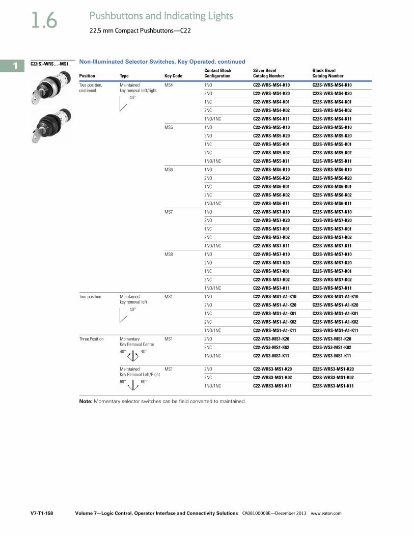
V7-T1-158 Volume 7—Logic Control, Operator Interface and Connectivity Solutions CA08100008E—December 2013 www.eaton.com
1
1
1
1
1
1
1
1
1
1
1
1
1
1
1
1
1
1
1
1
1
1
1
1
1
1
1
1
1
1
1.6 Pushbuttons and Indicating Lights
22.5 mm Compact Pushbuttons—C22
Non-Illuminated Selector Switches, Key Operated, continued
Note: Momentary selector switches can be field converted to maintained.
Position Type Key CodeContact Block Configuration
Silver BezelCatalog Number
Black BezelCatalog Number
Two-position, continued
Maintainedkey removal left/right
MS4 1NO C22-WRS-MS4-K10 C22S-WRS-MS4-K10
2NO C22-WRS-MS4-K20 C22S-WRS-MS4-K20
1NC C22-WRS-MS4-K01 C22S-WRS-MS4-K01
2NC C22-WRS-MS4-K02 C22S-WRS-MS4-K02
1NO/1NC C22-WRS-MS4-K11 C22S-WRS-MS4-K11
MS5 1NO C22-WRS-MS5-K10 C22S-WRS-MS5-K10
2NO C22-WRS-MS5-K20 C22S-WRS-MS5-K20
1NC C22-WRS-MS5-K01 C22S-WRS-MS5-K01
2NC C22-WRS-MS5-K02 C22S-WRS-MS5-K02
1NO/1NC C22-WRS-MS5-K11 C22S-WRS-MS5-K11
MS6 1NO C22-WRS-MS6-K10 C22S-WRS-MS6-K10
2NO C22-WRS-MS6-K20 C22S-WRS-MS6-K20
1NC C22-WRS-MS6-K01 C22S-WRS-MS6-K01
2NC C22-WRS-MS6-K02 C22S-WRS-MS6-K02
1NO/1NC C22-WRS-MS6-K11 C22S-WRS-MS6-K11
MS7 1NO C22-WRS-MS7-K10 C22S-WRS-MS7-K10
2NO C22-WRS-MS7-K20 C22S-WRS-MS7-K20
1NC C22-WRS-MS7-K01 C22S-WRS-MS7-K01
2NC C22-WRS-MS7-K02 C22S-WRS-MS7-K02
1NO/1NC C22-WRS-MS7-K11 C22S-WRS-MS7-K11
MS8 1NO C22-WRS-MS7-K10 C22S-WRS-MS7-K10
2NO C22-WRS-MS7-K20 C22S-WRS-MS7-K20
1NC C22-WRS-MS7-K01 C22S-WRS-MS7-K01
2NC C22-WRS-MS7-K02 C22S-WRS-MS7-K02
1NO/1NC C22-WRS-MS7-K11 C22S-WRS-MS7-K11
Two-position Maintainedkey removal left
MS1 1NO C22-WRS-MS1-A1-K10 C22S-WRS-MS1-A1-K10
2NO C22-WRS-MS1-A1-K20 C22S-WRS-MS1-A1-K20
1NC C22-WRS-MS1-A1-K01 C22S-WRS-MS1-A1-K01
2NC C22-WRS-MS1-A1-K02 C22S-WRS-MS1-A1-K02
1NO/1NC C22-WRS-MS1-A1-K11 C22S-WRS-MS1-A1-K11
Three Position MomentaryKey Removal Center
MS1 2NO C22-WS3-MS1-K20 C22S-WS3-MS1-K20
2NC C22-WS3-MS1-K02 C22S-WS3-MS1-K02
1NO/1NC C22-WS3-MS1-K11 C22S-WS3-MS1-K11
MaintainedKey Removal Left/Right
MS1 2NO C22-WRS3-MS1-K20 C22S-WRS3-MS1-K20
2NC C22-WRS3-MS1-K02 C22S-WRS3-MS1-K02
1NO/1NC C22-WRS3-MS1-K11 C22S-WRS3-MS1-K11
C22(S)-WRS…-MS1_
40°
40°
40°40°
60°60°

Volume 7—Logic Control, Operator Interface and Connectivity Solutions CA08100008E—December 2013 www.eaton.com V7-T1-159
1
1
1
1
1
1
1
1
1
1
1
1
1
1
1
1
1
1
1
1
1
1
1
1
1
1
1
1
1
1
1.6Pushbuttons and Indicating Lights
22.5 mm Compact Pushbuttons—C22
Technical Data and Specifications
22.5 mm Compact Pushbuttons—C22
Pushbutton Actuators Illuminated Pushbuttons C22 Indicator
Lights C22Selector Switch Actuators C22
Key-Operated Buttons C22
Emergency Stop/Emergency Switching OFF Pushbuttons C22Description Unit Momentary Maintained
General
Standards IEC/EN 60947 VDE 0660
Lifespan, mechanical Operations x 106 5 1 — 1 0.1 0.05
Operating frequency Operations/h >3600 >3600 — >2000 >100 >300
Actuating force N >5 >5 — — — >50
Operating torque Nm — — — >0.3 >0.5 —
Terminal screw tightening torque Nm 0.8 0.8 0.8 0.8 0.8 0.8
Threaded ring tightening torque Nm 2 2 2 2 2 2
Protection type IP67, IP69K IP67, IP69K IP67, IP69K IP65 IP66 IP67, IP69K
Climatic proofing Damp heat, constant, to IEC 60068-2-78Damp heat, cyclic, to IEC 60068-2-30
Ambient temperature
Open °C –25° to 70° –25° to 70° –25° to 70° –25° to 70° –25° to 70° –25° to 70°
Storage °C –30° to 80° –30° to 80° –30° to 80° –30° to 80° –30° to 80° –30° to 80°
Mounting position As required As required As required As required As required As required
Mechanical shock resistance to IEC 60068-2-27 Shock duration 11 ms, half-sinusoidal
g 30 30 30 30 30 30
Terminal capacities
Solid mm2 2 x 0.5–1.5 2 x 0.5–1.5 2 x 0.5–1.5 2 x 0.5–1.5 2 x 0.5–1.5 2 x 0.5–1.5
Flexible with ferrule mm2 2 x 0.5–1.5 2 x 0.5–1.5 2 x 0.5–1.5 2 x 0.5–1.5 2 x 0.5–1.5 2 x 0.5–1.5
Contacts
Rated impulse withstand voltage Uimp Vac 4000 4000 4000 4000 4000 4000
Rated insulation voltage Ui V 250 250 250 250 250 250
Overvoltage category/pollution degree
III/3 III/3 III/3 III/3 III/3 III/3
Control circuit reliability
at 5 Vdc/1 mA HF Fault probability
Values follow Values follow — Values follow Values follow Values follow
at 17 Vdc/7 mA HF Fault probability
N/O contact: statistically determined 1 failure per 17 x 106 operations
N/C contact: statistically determined 1 failure per 0.9 x 10⁶ operations
— N/O contact: statistically determined 1 failure per 17 x 106 operations
N/C contact: statistically determined 1 failure per 0.9 x 10⁶ operations
at 24 Vdc/5 mA HF Fault probability
Values follow Values follow — Values follow Values follow Values follow
Max. short-circuit protective device
Fuse gG/gL A 10 10 — 10 10 10

V7-T1-160 Volume 7—Logic Control, Operator Interface and Connectivity Solutions CA08100008E—December 2013 www.eaton.com
1
1
1
1
1
1
1
1
1
1
1
1
1
1
1
1
1
1
1
1
1
1
1
1
1
1
1
1
1
1
1.6 Pushbuttons and Indicating Lights
22.5 mm Compact Pushbuttons—C22
22.5 mm Compact Pushbuttons—C22, continued
Contact Travel
Contact Travel Diagram
Push-button Actuators Illuminated Pushbuttons C22 Indicator
Lights C22Selector Switch Actuators C22
Key-Operated Buttons C22
Emergency Stop/Emergency Switching OFF Pushbuttons C22Description Unit Momentary Maintained
Switching Capacity
Rated operational current
AC-15
24V Ie A 4 4 — 4 4 4
110V Ie A 2 2 — 2 2 2
230V Ie A 1.5 1.5 — 1.5 1.5 1.5
DC-13
24V Ie A 3 3 — 3 3 3
60V Ie A 1 1 — 1 1 1
110V Ie A 0.6 0.6 — 0.6 0.6 0.6
220V Ie A 0.3 0.3 — 0.3 0.3 0.3
Lifespan, electrical
AC-15
230V/0.5A Operations x 106 0.4 0.4 — 0.4 0.4 0.4
230V/1.0A x 106 0.6 0.6 — 0.6 0.6 0.6
0
0
3.15 5.5
5.52.2
3
4
2
1
Contact closed
Contact open

Volume 7—Logic Control, Operator Interface and Connectivity Solutions CA08100008E—December 2013 www.eaton.com V7-T1-161
1
1
1
1
1
1
1
1
1
1
1
1
1
1
1
1
1
1
1
1
1
1
1
1
1
1
1
1
1
1
1.6Pushbuttons and Indicating Lights
22.5 mm Compact Pushbuttons—C22
DimensionsApproximate Dimensions in mm [in]
Illuminated Pushbuttons
Flat
C22(S)-DRL_/C22(S)-DL_
Extended
C22(S)-DRLH_/C22(S)-DLH_
Pushbutton Actuators
Flat
C22(S)-DR_/C22(S)-D_
Extended
C22(S)-DRH_/C22(S)-DH_
Indicating Lights
Flat
C22-L_
Ø29.7[1.17]
M22 x 1.5
54.6 [2.15]
1.0–6.0[0.04–0.24]
6.0[0.24]
4.0[0.16]
Ø29.5[1.16]
9.6[0.38]
20.2[0.80]
10.4[0.41]
Ø29.7[1.17]
M22 x 1.5
60.9 [2.40]
1.0–6.0[0.04–0.24]
6.0[0.24]
4.0[0.16]
Ø29.5[1.16]
9.6[0.38]
20.2[0.80]
16.7[0.66]
Ø29.7[1.17]
M22 x 1.5
54.6 [2.15]
1.0–6.0[0.04–0.24]
6.0[0.24]
4.0[0.16]
Ø29.5[1.16]
9.6[0.38]
20.2[0.80]
10.4[0.41]
Ø29.7[1.17]
M22 x 1.5
60.9 [2.40]
1.0–6.0[0.04–0.24]
6.0[0.24]
4.0[0.16]
Ø29.5[1.16]
9.6[0.38]
20.2[0.80]
16.7[0.66]
Ø29.7[1.17]
M22 x 1.5
55.9 [2.20]
1.0–6.0[0.04–0.24]
6.0[0.24]
4.0[0.16]
Ø29.5[1.16]
9.6[0.38]
Ø20.2[0.80]
11.7[0.46]

V7-T1-162 Volume 7—Logic Control, Operator Interface and Connectivity Solutions CA08100008E—December 2013 www.eaton.com
1
1
1
1
1
1
1
1
1
1
1
1
1
1
1
1
1
1
1
1
1
1
1
1
1
1
1
1
1
1
1.6 Pushbuttons and Indicating Lights
22.5 mm Compact Pushbuttons—C22
Approximate Dimensions in mm [in]
Emergency Stop/Emergency Switching OFF Pushbuttons
C22-PVT45P_
C22-PVT45P-MS_
C22-PVT60P_
C22-PVT45P-RS_
C22-PVT60P-MS_
C22-PVT60P-MS_
Ø45.0[1.77]
93.0 [3.66]
1.0–6.0[0.04–0.24]
6.0[0.24]
4.0[0.16]
9.3[0.37]
M22 x 1.5
Ø29.5[1.16]
Ø20.4[0.80]
48.0[1.89]
45.0[1.77]
M22 x 1.5
1.0–6.0[0.04–0.24]
6.0[0.24]
4.0[0.16]
Ø29.5[1.16]
9.3[0.37]
Ø20.4[0.80]
Ø45.0[1.17]
120.0 [4.72]
75.0 [2.95]
48.0[1.89] 45.0
[1.77]
Ø60.0[2.36]
92.0 [3.62]
1.0–6.0[0.04–0.24]
6.0[0.24]
4.0[0.16]
9.3[0.37]
M22 x 1.5
Ø29.5[1.16]
Ø20.4[0.80]48.0
[1.89]45.0
[1.77]
M22 x 1.5
1.0–6.0[0.04–0.24]
6.0[0.24]
4.0[0.16]
Ø29.5[1.16]
9.3[0.37]
Ø20.4[0.80]
Ø45.0[1.77]
116.0 [4.57]
71.0 [2.80]
48.0[1.89] 45.0
[1.77]
M22 x 1.5
1.0–6.0[0.04–0.24]
6.0[0.24]
4.0[0.16]
Ø29.5[1.16]
9.3[0.37]
Ø20.4[0.80]
Ø60.0[2.36]
120.0 [4.72]
75.0 [2.95]
48.0[1.89]
45.0[1.77]
M22 x 1.5
1.0–6.0[0.04–0.24]
6.0[0.24]
4.0[0.16]
Ø29.5[1.16]
9.3[0.37]
Ø20.4[0.80]
Ø60.0[2.36]
116.0 [4.57]
71.0 [2.80]
48.0[1.89]
45.0[1.77]

Volume 7—Logic Control, Operator Interface and Connectivity Solutions CA08100008E—December 2013 www.eaton.com V7-T1-163
1
1
1
1
1
1
1
1
1
1
1
1
1
1
1
1
1
1
1
1
1
1
1
1
1
1
1
1
1
1
1.6Pushbuttons and Indicating Lights
22.5 mm Compact Pushbuttons—C22
Approximate Dimensions in mm [in]
Selector Switch Actuators
C22(S)-W(R)K_
Selector Switch Actuators/V Position
C22(S)-W(R)KV_
Key Operated Actuators
C22(S)-WS(3)-MS_/C22(S)-WRS(3)-MS_
C22(S)-WS(3)-RS_/C22(S)-WRS(3)-RS_
Ø29.7[1.17]
M22 x 1.5
72.0 [2.83]
1.0–6.0[0.04–0.24]
6.0[0.24]
4.0[0.16]
Ø29.5[1.16]
9.6[0.38]
20.2[0.80]
27.8[1.09]
Ø29.7[1.17]
M22 x 1.5
72.0 [2.83]
1.0–6.0[0.04–0.24]
6.0[0.24]
4.0[0.16]
Ø29.5[1.16]
9.6[0.38]
20.2[0.80]
27.8[1.09]
30°
M22 x 1.5
1.0–6.0[0.04–0.24]
6.0[0.24]
4.0[0.16]
Ø29.5[1.16]
9.6[0.38]
20.2[0.80]
Ø29.7[1.17]
92.1 [3.63]
20.8[0.82]
47.9 [1.89]
44.2 [1.74]
M22 x 1.5
1.0–6.0[0.04–0.24]
6.0[0.24]
4.0[0.16]
Ø29.5[1.16]
9.6[0.38]
20.2[0.80]
Ø29.7[1.17]
92.1 [3.63]
24.9[0.98]
47.9 [1.89]
44.2 [1.74]

V7-T1-164 Volume 7—Logic Control, Operator Interface and Connectivity Solutions CA08100008E—December 2013 www.eaton.com
1
1
1
1
1
1
1
1
1
1
1
1
1
1
1
1
1
1
1
1
1
1
1
1
1
1
1
1
1
1
1.7 Pushbuttons and Indicating Lights
30.5 mm Square Multifunction Watertight/Oiltight—E30
30.5 mm Square Multifunction Watertight/Oiltight—E30 ContentsDescription Page
30.5 mm Square Multifunction Watertight/Oiltight—E30
Product Identification . . . . . . . . . . . . . . . . . . . . V7-T1-165
Product Selection Operators . . . . . . . . . . . . . . . . . . . . . . . . . . V7-T1-166
Operator Components . . . . . . . . . . . . . . . . V7-T1-169
Accessories . . . . . . . . . . . . . . . . . . . . . . . . . . . V7-T1-175
Options . . . . . . . . . . . . . . . . . . . . . . . . . . . . . . V7-T1-176
Replacement Parts . . . . . . . . . . . . . . . . . . . . . . V7-T1-179
Technical Data and Specifications . . . . . . . . . . V7-T1-180
Dimensions . . . . . . . . . . . . . . . . . . . . . . . . . . . V7-T1-181
Product DescriptionThe E30 industrial pushbutton and indicating light line from Eaton’s Electrical Sector features a wide selection of square, multifunction operators which conveniently mount in a standard 30.5 mm (1-13/64 in) diameter panel hole. Up to six input and indicating functions can be grouped into a single operating head, saving valuable panel space. Attractive square operator styling, coupled with custom legending of colored buttons and lenses and many special function accessories, makes E30 components ideally suited for use on control consoles and for a variety of industrial OEM applications.
FeaturesType E30 control units consist of a basic operator with one or more buttons and lenses and contact block selection dependent on the specific operator configuration.
● Pushbutton operators will accommodate up to four single depth stackable contact blocks behind each operating button, up to eight circuits maximum.
● Indicating lights are supplied complete with either a transformer light unit up to 600 Vac supply line voltage or full voltage light unit up to 120 Vac/Vdc supply line voltage.
● Combination pushbutton with indicating light operators are supplied complete with a transformer or full voltage unit. Contact blocks must be ordered separately, up to four circuits maximum.
Die Cast ConstructionEach operator has high pressure type seals to prevent the passage of oil and other contaminants through the operator into the contact structure or panel interior. Each operator uses a Buna N cork gasket between the mounting flange on the operator and the panel to maintain oiltightness.
Standards and Certifications ● UL Listed—File No.
E131568● CSA Certified—File No.
LR68551
Ingress Protection● Single and dual indicating
lights● UL (NEMA) Type 1, 2, 3,
3R, 3S, 4, 4X, 12, 13
● All other operators● UL (NEMA) Type 3, 3R,
4, 4X, 12, 13
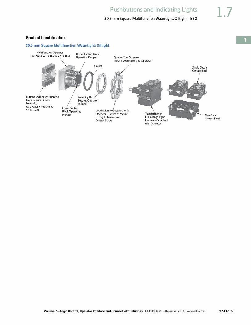
Volume 7—Logic Control, Operator Interface and Connectivity Solutions CA08100008E—December 2013 www.eaton.com V7-T1-165
1
1
1
1
1
1
1
1
1
1
1
1
1
1
1
1
1
1
1
1
1
1
1
1
1
1
1
1
1
1
1.7Pushbuttons and Indicating Lights
30.5 mm Square Multifunction Watertight/Oiltight—E30
Product Identification
30.5 mm Square Multifunction Watertight/Oiltight
Two Circuit
Contact Block
Transformer orFull Voltage LightElement—Supplied
with Operator
Locking Ring—Supplied withOperator—Serves as Mountfor Light Element and
Contact Blocks
Retaining NutSecures Operator
to Panel
Lower ContactBlock OperatingPlunger
Buttons and Lenses Supplied
Blank or with Custom Legend(s) (see Pages V7-T1-169 to
V7-T1-173)
Multifunction Operator
(see Pages V7-T1-166 to V7-T1-168)Upper Contact BlockOperating Plunger
Gasket
Quarter Turn Screw—
Mounts Locking Ring to Operator
Single CircuitContact Block

V7-T1-166 Volume 7—Logic Control, Operator Interface and Connectivity Solutions CA08100008E—December 2013 www.eaton.com
1
1
1
1
1
1
1
1
1
1
1
1
1
1
1
1
1
1
1
1
1
1
1
1
1
1
1
1
1
1
1.7 Pushbuttons and Indicating Lights
30.5 mm Square Multifunction Watertight/Oiltight—E30
Product SelectionOperators
When Ordering a Complete E30 Control Unit Specify
Square Multifunction OperatorsUL (NEMA) Type 3, 3R, 4, 4X, 12, 13
Single Button Operator/without Button (Order Button Separately)
Two Button Operator/without Buttons (Order Buttons Separately)
Two Button Operator with Long (OFF) Release Bar—Includes OFF Bar/Button (Order Other Buttons Separately)
Notes1 Order from table on Page V7-T1-169.2 Limited to two single circuit, one double circuit 600V or two 120V (E30KLA9) contact blocks behind each button.3 Buttons are interlocked so that one of the two is maintained at all times.
Depressing the other button releases the maintained button and maintains the depressed button.4 Operators are supplied as standard with red extended bar(s) marked “OFF” as shown in sketch.
For other colors or markings, contact your nearest Eaton Distributor or call our Customer Service Center 1-800-356-1243. For replacement of standard red release bar, order E30KR100.
5 Order from table on Page V7-T1-170.6 Limited to two single circuit, one double circuit 600V or two 120V (E30KLA9) contact blocks behind each button.
Catalog Number of … Ordering Example (E30AB)
Operator E30KB130 “START”
Button(s) E30KB231 “STOP”
Contact block(s) E30KLA1 1NO
Accessories (if required) E30KLA2 1NC
Button TypeRequired 1 Operation Special Features Catalog Number
Momentary — E30AA
Button TypesRequired 1
OperationSpecial Features Catalog NumberTop Button Bottom Button
Momentary Momentary — E30AB
Momentary Momentary With mechanicalinterlock
E30AC
Maintained (all contacts)
Release(all contacts)
— E30AD 2
Maintained (all contacts)
Release(all contacts)
With mechanicalinterlock
E30AP 23
Button TypesRequired 45
OperationSpecial Features Catalog NumberTop Button Bottom Button
Maintained Maintained — E30AF
Maintained Maintained With mechanicalinterlock
E30AG
Maintained Momentary With mechanicalinterlock
E30AH
Maintained(all contacts)
Maintained(bottom contacts only)
Top button operatesboth top andbottom contacts
E30AK 6
Shown with Extended Button
Single Button Operator
Two Button Operator
Shown with Extended Buttons
Two Button Operator
Shown with Long Release Bar

Volume 7—Logic Control, Operator Interface and Connectivity Solutions CA08100008E—December 2013 www.eaton.com V7-T1-167
1
1
1
1
1
1
1
1
1
1
1
1
1
1
1
1
1
1
1
1
1
1
1
1
1
1
1
1
1
1
1.7Pushbuttons and Indicating Lights
30.5 mm Square Multifunction Watertight/Oiltight—E30
Square Multifunction Operators and Indicating LightsUL (NEMA) Type 3, 3R, 4, 4X, 12, 13
Two Button Operator with (OFF) Release—Includes OFF Bar/Button(s)(Order Other Buttons Separately)
Single Indicating Light Unit/without Lens (Order Lens Separately)
Dual Indicating Light Unit/without Lenses (Order Lenses Separately)
Notes1 Order from table on Page V7-T1-170.2 Operators are supplied as standard with red extended release bar(s) marked “OFF” as shown in sketch. For other colors or
markings, contact your nearest Eaton Distributor or call our Customer Service Center 1-800-356-1243. For replacement of standard red release bar, order E30KR101.
3 Order from table on Page V7-T1-171.4 Light units will also accept LED lamps. For LED part numbers, see table on Page V7-T1-179.5 Order from table on Page V7-T1-172.
Button TypesRequired 12
OperationSpecial Features Catalog NumberTop Button Bottom Button
Maintained Momentary Release bar for top button
E30AL
Maintained Maintained Individual releasebars for each button
E30AN
Maintainedwith interlock
Maintainedwith interlock
Individual releasebars for each button
E30AM
Lens TypeRequired 3
Type of Light ElementTransformer(60/50 Hertz AC)
Full Voltage(60/50 Hertz AC or DC)
VoltageLamp Number 4 Catalog Number Voltage
Lamp Number 4 Catalog Number
120 6PSB E30BA 24 24PSB E30BJ
120 120PSB E30BM
Lens TypesRequired 5
Type of Light ElementTransformer(60/50 Hertz AC)
Full Voltage(60/50 Hertz AC or DC)
VoltageLamp Number 4 Catalog Number Voltage
Lamp Number 4 Catalog Number
120 6PSB E30CA 24 24PSB E30CJ
120 120PSB E30CM
Shown with Release Bar for Top Button
Two Button Operator
Shown with Release Bars for Each Button
Two Button Operator
Shown with Lens
Single Indicating Light Unit
Shown with Lens
Dual Indicating Light Unit

V7-T1-168 Volume 7—Logic Control, Operator Interface and Connectivity Solutions CA08100008E—December 2013 www.eaton.com
1
1
1
1
1
1
1
1
1
1
1
1
1
1
1
1
1
1
1
1
1
1
1
1
1
1
1
1
1
1
1.7 Pushbuttons and Indicating Lights
30.5 mm Square Multifunction Watertight/Oiltight—E30
UL (NEMA) Type 3, 3R, 4, 4X, 12, 13
Single Button Operator with Indicating Light/without Button or Lens (Order Button and Lens Separately)
Single Button Operator with (OFF) Release Bar and Indicating Light—Includes OFF Bar/Button (Order Other Button and Lens Separately)
Two Button Operator with Indicating Light/without Buttons or Lens (Order Buttons and Lens Separately)
Two Button Operator with Dual Indicating Lights/without Buttons and Lens
Notes1 Order from tables on Pages V7-T1-169 to V7-T1-173.2 Light units will also accept LED lamps. For LED part numbers, see table on Page V7-T1-179.3 Operators are supplied as standard with red extended release bar(s) marked “OFF” as shown in sketch. For other colors or
markings, contact your nearest Eaton Distributor or call our Customer Service Center 1-800-356-1243. For replacement of standard red release bar, order E30KR101.
4 Order from tables on Pages V7-T1-171 and V7-T1-172.
Button and Lens Types Required 1
Operation(BottomButton)
Type of Light ElementTransformer(60/50 Hertz AC)
Full Voltage(60/50 Hertz AC or DC)
VoltageLamp Number 2 Catalog Number Voltage
Lamp Number 2 Catalog Number
Momentary 120 6PSB E30DA 24 24PSB E30DX3
120 120PSB E30DF
Button and Lens Types Required 1
Operation(BottomButton)
Type of Light ElementTransformer(60/50 Hertz AC)
Full Voltage(60/50 Hertz AC or DC)
VoltageLamp Number 3 Catalog Number Voltage
Lamp Number 2 Catalog Number
Maintained 120 6PSB E30DG 24 24PSB E30DX13
120 120PSB E30DM
Button and Lens Types Required 4
Button Operation
Type of Light ElementTransformer(60/50 Hertz AC)
Full Voltage(60/50 Hertz AC or DC)
VoltageLamp Number 2 Catalog Number Voltage
Lamp Number 2 Catalog Number
Momentary 120 6PSB E30EA 24 24PSB E30EX3
120 120PSB E30EF
Momentary with interlock
120 6PSB E30EG 24 24PSB E30EX13
120 120PSB E30EM
Button and Lens Types Required 1
Button Operation
Type of Light ElementTransformer(60/50 Hertz AC)
Full Voltage(60/50 Hertz AC or DC)
VoltageLamp Number 2 Catalog Number Voltage
Lamp Number 2 Catalog Number
Momentary 120 6PSB E30JA 24 24PSB E30JX3
120 120PSB E30JF
Shown with Button and Lens
Single Button Operator and Indicating Light
Shown with Button and Lens
Single Button Operator with Release Bar and Indicating Light
Shown with Button and Lens
Two Button Operator with Indicating Light
Shown with Button and Lens
Two Button Operator with Dual Indicating Lights

Volume 7—Logic Control, Operator Interface and Connectivity Solutions CA08100008E—December 2013 www.eaton.com V7-T1-169
1
1
1
1
1
1
1
1
1
1
1
1
1
1
1
1
1
1
1
1
1
1
1
1
1
1
1
1
1
1
1.7Pushbuttons and Indicating Lights
30.5 mm Square Multifunction Watertight/Oiltight—E30
Operator Components
Operating Buttons Only
Type A Buttons with Standard Markings 1
Type B Buttons with Standard Markings 2
Notes1 Use with operator E30AA, legend characters 3/16 in (4.8 mm) high.2 Use with operators E30AB thru AE, AL and DA thru DF, legend characters 3/16 in (4.8 mm) high.
ButtonApplication Color Marking
Extended ButtonCatalog Number
Short ButtonCatalog Number Color Marking
Extended ButtonCatalog Number
Short ButtonCatalog Number
Black Blank E30KA100 E30KA150 Green START E30KA330 E30KA380
START — E30KA180 Yellow Blank E30KA400 E30KA450
Red Blank E30KA200 E30KA250 White Blank E30KA500 E30KA550
EMERG. STOP E30KA204 — Gray Blank E30KA600 E30KA650
OFF E30KA218 E30KA268 Brown Blank E30KA700 E30KA750
STOP E30KA231 E30KA281 Orange Blank E30KA800 E30KA950
Green Blank E30KA300 E30KA350 Blue Blank E30KA900 E30KA950
ButtonApplication Color Marking
Extended ButtonCatalog Number
Short ButtonCatalog Number Color Marking
Extended ButtonCatalog Number
Short ButtonCatalog Number
Black Blank E30KB100 E30KB150 Black REVERSE E30KB125 E30KB175
AUTO E30KB101 E30KB151 RUN E30KB126 E30KB176
CLOSE E30KB102 E30KB152 SLOW E30KB128 E30KB178
DOWN E30KB103 E30KB153 START E30KB130 E30KB180
FAST E30KB105 E30KB155 TEST E30KB132 E30KB182
FORWARD E30KB107 E30KB157 UP E30KB134 E30KB184
HIGH E30KB109 E30KB159 Red Blank E30KB200 E30KB250
IN E30KB110 E30KB160 EMERG. STOP E30KB204 —
INCH E30KB111 E30KB161 OFF E30KB218 E30KB268
JOG E30KB112 E30KB162 STOP E30KB231 E30KB281
JOG FOR. E30KB113 E30KB163 Green Blank E30KB300 E30KB350
JOG REV. E30KB114 E30KB164 START E30KB330 E30KB380
LOW E30KB115 E30KB165 Yellow Blank E30KB400 E30KB450
LOWER E30KB116 E30KB166 White Blank E30KB500 E30KB550
MAN E30KB117 E30KB167 AUTO E30KB501 —
ON E30KB119 E30KB169 HAND E30KB508 —
OPEN E30KB120 E30KB170 Gray Blank E30KB600 E30KB650
OUT E30KB121 E30KB171 Brown Blank E30KB700 E30KB750
RAISE E30KB122 E30KB172 Orange Blank E30KB800 E30KB850
RESET E30KB124 E30KB174 Blue Blank E30KB900 E30KB950
Type A Extended Button
Type B Extended Button

V7-T1-170 Volume 7—Logic Control, Operator Interface and Connectivity Solutions CA08100008E—December 2013 www.eaton.com
1
1
1
1
1
1
1
1
1
1
1
1
1
1
1
1
1
1
1
1
1
1
1
1
1
1
1
1
1
1
1.7 Pushbuttons and Indicating Lights
30.5 mm Square Multifunction Watertight/Oiltight—E30
Type C Buttons with Standard Markings 1
Note1 Use with operators E30AF thru AK, AL thru AM and DG thru DM, legend characters 1/8 in (3.2 mm) high.
ButtonApplication Color Marking
Extended ButtonCatalog Number
Short ButtonCatalog Number Color Marking
Extended ButtonCatalog Number
Short ButtonCatalog Number
Black Blank E30KC100 E30KC150 Black RESET E30KC124 E30KC174
AUTO E30KC101 E30KC151 REVERSE E30KC125 E30KC175
CLOSE E30KC102 E30KC152 RUN E30KC126 E30KC176
DOWN E30KC103 E30KC153 SLOW E30KC128 E30KC178
FAST E30KC105 E30KC155 START E30KC130 E30KC180
FORWARD E30KC107 E30KC157 TEST E30KC132 E30KC182
HAND E30KC108 E30KC158 UP E30KC134 E30KC184
HIGH E30KC109 E30KC159 Red Blank E30KC200 E30KC250
IN E30KC110 E30KC160 OFF E30KC218 —
INCH E30KC111 E30KC161 STOP E30KC231 E30KC281
JOG E30KC112 E30KC162 Green Blank E30KC300 E30KC350
JOG FOR. E30KC113 E30KC163 START E30KC330 E30KC380
JOG REV. E30KC114 E30KC164 Yellow Blank E30KC400 E30KC450
LOW E30KC115 E30KC165 White Blank E30KC500 E30KC550
LOWER E30KC116 E30KC166 Gray Blank E30KC600 E30KC650
MAN E30KC117 E30KC167 Brown Blank E30KC700 E30KC750
ON E30KC119 E30KC169 Orange Blank E30KC800 E30KC850
OPEN E30KC120 E30KC170 Blue Blank E30KC900 E30KC950
OUT E30KC121 E30KC171
RAISE E30KC122 E30KC172
Type C Extended Button

Volume 7—Logic Control, Operator Interface and Connectivity Solutions CA08100008E—December 2013 www.eaton.com V7-T1-171
1
1
1
1
1
1
1
1
1
1
1
1
1
1
1
1
1
1
1
1
1
1
1
1
1
1
1
1
1
1
1.7Pushbuttons and Indicating Lights
30.5 mm Square Multifunction Watertight/Oiltight—E30
Operating Buttons and Lens OnlyStandard Color Buttons and Lens Marking 1
Black lettering on — White, Amber, Yellow and Clear.White lettering on — Green, Red, Blue, Brown, Black, Orange and Gray.
Type E Buttons with Standard Markings 2
Type F Lenses with Standard Markings 3
Notes1 For lenses with special markings or with standard markings but in a different color, refer to instructions on
Pages V7-T1-176 to V7-T1-178.2 Use with operators E30EA thru EM, FA thru FM and JA thru JM, legend characters 1/8 in (3.2 mm) high.3 Use with operators E30BA thru BY, legend characters 3/16 in (4.8 mm) high.
ButtonApplication Color Marking
Extended ButtonCatalog Number Color Marking
Extended ButtonCatalog Number
Black Blank E30KE100 Black RESET E30KE124
CLOSE E30KE102 REVERSE E30KE125
DOWN E30KE103 RUN E30KE126
FAST E30KE105 SLOW E30KE128
FORWARD E30KE107 START E30KE130
HIGH E30KE109 TEST E30KE132
IN E30KE110 UP E30KE134
INCH E30KE111 Red Blank E30KE200
JOG E30KE112 OFF E30KE218
JOG FOR. E30KE113 STOP E30KE231
JOG REV. E30KE114 Green Blank E30KE300
LOW E30KE115 START E30KE330
LOWER E30KE116 Yellow Blank E30KE400
ON E30KE119 White Blank E30KE500
OPEN E30KE120 Gray Blank E30KE600
OUT E30KE121 Brown Blank E30KE700
PHASE E30KE122 Orange Blank E30KE800
Blue Blank E30KE900
ButtonApplication Color Marking Catalog Number Color Marking Catalog Number
Red Blank E30KF10 Green OFF E30KF22
MOTOR RUN E30KF11 Amber Blank E30KF30
ON E30KF12 Blue Blank E30KF40
POWER ON E30KF13 Clear Blank E30KF50
Green Blank E30KF20 White Blank E30KF60
MOTOR STOP E30KF21
MOTOR RUN E30KF23
Type E Button
Type F Lens

V7-T1-172 Volume 7—Logic Control, Operator Interface and Connectivity Solutions CA08100008E—December 2013 www.eaton.com
1
1
1
1
1
1
1
1
1
1
1
1
1
1
1
1
1
1
1
1
1
1
1
1
1
1
1
1
1
1
1.7 Pushbuttons and Indicating Lights
30.5 mm Square Multifunction Watertight/Oiltight—E30
Operating Lens OnlyStandard Color Buttons and Lens Marking 1
Black lettering on — White, Amber, Yellow and Clear.White lettering on — Green, Red, Blue, Brown, Black, Orange and Gray.
Type G Lenses with Standard Markings 2
Type J Lenses with Standard Markings 3
Type K Lenses with Standard Markings (Sold in Pairs Only) 4
Notes1 For lenses with special markings or with standard markings but in a different color, refer to instructions on
Pages V7-T1-176 to V7-T1-178.2 Use with operators E30CA thru CM and DA thru DM, legend characters 3/16 in (4.8 mm) high except MOTOR RUN,
POWER ON and MOTOR STOP are 1/8 in (3.2 mm) high.3 Use with operators E30EA thru EM, FA thru FM and GA thru GM, legend characters 1/8 in (3.2 mm) high.4 Use with operators E30JA thru JW, legend characters 1/8 in (3.2 mm) high
LensApplication Color Marking Catalog Number Color Marking Catalog Number
Red Blank E30KG10 Green OFF E30KG22
MOTOR RUN E30KG11 READY E30KG23
ON E30KG12 Amber Blank E30KG30
POWER ON E30KG13 Blue Blank E30KG40
Green Blank E30KG20 Clear Blank E30KG50
MOTOR RUN E30KG24 White Blank E30KG60
MOTOR STOP E30KG21
LensApplication Color Marking Catalog Number Color Marking Catalog Number
Red Blank E30KJ10 Green OFF E30KJ22
MOTOR RUN E30KJ11 ON E30KJ24
ON E30KJ12 Amber Blank E30KJ30
POWER ON E30KJ13 Blue Blank E30KJ40
MOTOR STOP E30KJ14 Clear Blank E30KJ50
Green Blank E30KJ20 White Blank E30KJ60
MOTOR STOP E30KJ21
MOTOR RUN E30KJ23
LensApplication
Color Marking
Catalog Number
Left Hand Lens
Right Hand Lens
Left Hand Lens
Right Hand Lens
Red Red ON ON E30KK12
Green ON OFF E30KK13
Green OFF OFF E30KK22
Red OFF ON E30KK23
Type G Lens
Type J Lens
Type K Lenses
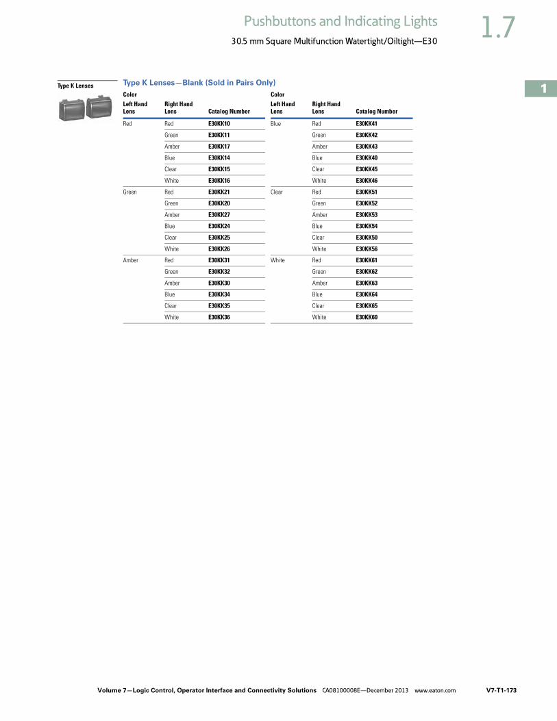
Volume 7—Logic Control, Operator Interface and Connectivity Solutions CA08100008E—December 2013 www.eaton.com V7-T1-173
1
1
1
1
1
1
1
1
1
1
1
1
1
1
1
1
1
1
1
1
1
1
1
1
1
1
1
1
1
1
1.7Pushbuttons and Indicating Lights
30.5 mm Square Multifunction Watertight/Oiltight—E30
Type K Lenses—Blank (Sold in Pairs Only)
Color ColorLeft Hand Lens
Right Hand Lens Catalog Number
Left Hand Lens
Right Hand Lens Catalog Number
Red Red E30KK10 Blue Red E30KK41
Green E30KK11 Green E30KK42
Amber E30KK17 Amber E30KK43
Blue E30KK14 Blue E30KK40
Clear E30KK15 Clear E30KK45
White E30KK16 White E30KK46
Green Red E30KK21 Clear Red E30KK51
Green E30KK20 Green E30KK52
Amber E30KK27 Amber E30KK53
Blue E30KK24 Blue E30KK54
Clear E30KK25 Clear E30KK50
White E30KK26 White E30KK56
Amber Red E30KK31 White Red E30KK61
Green E30KK32 Green E30KK62
Amber E30KK30 Amber E30KK63
Blue E30KK34 Blue E30KK64
Clear E30KK35 Clear E30KK65
White E30KK36 White E30KK60
Type K Lenses

V7-T1-174 Volume 7—Logic Control, Operator Interface and Connectivity Solutions CA08100008E—December 2013 www.eaton.com
1
1
1
1
1
1
1
1
1
1
1
1
1
1
1
1
1
1
1
1
1
1
1
1
1
1
1
1
1
1
1.7 Pushbuttons and Indicating Lights
30.5 mm Square Multifunction Watertight/Oiltight—E30
Contact BlocksStandard Contact Blocks—Molded, phenolic construction. Enclosed silver contacts with reliability “nibs” that improve the reliability of switching performance under dry circuit, corrosive atmosphere and fine dust conditions. For more extreme conditions, the logic level contact blocks described below are recommended.
Logic Level Contact Blocks—Feature palladium contacts. Palladium, which is more inert than gold, is well suited for voltages and currents approaching zero. When mounted in an enclosure rated for highly corrosive environments, logic level contact blocks can be used where exposure to chemicals may cause failure to other types of materials.
Mounting LimitationsSee the contact block mounting limitations for Type E30 pushbutton and combination pushbutton and light operators on this page. Mounting positions 1 thru 8 indicate single depth contact blocks. Each of these positions can represent either a single circuit 600 volt block or a two-circuit 120 volt block. The two-circuit 600 volt block requires two of the numbered positions shown.
Mounting Positions
Contact Block Selection
Notes1 Except operator E30AD, AJ or AK which will accommodate contact blocks 1, 2, 5 and 6 only. (See Mounting Positions above.)2 Individually boxed contact blocks master packed 10 per carton.3 Supplied with non-stacking screws. Limited to 2 contact blocks mounted in positions 1 and 5.4 Do not use with maintained operators.5 Contacts must be same polarity.
Catalog Numberof Operator
Contact Blocks Can Be Mounted in Positions Listed BelowUpper Stack Lower Stack
E30AA thru E30AM 1 1-2-3-4 5-6-7-8
E30BA thru E30CM None None
E30DA thru E30DM None 5-6-7-8
E30EA thru E30GM 2-3-4 6-7-8
E30JA thru E30JM 3-4 7-8
Contact BlockMountingPositions
Upper ContactBlock Stack
Upper Contact Block Stack Operating Plunger
Lower Contact Block StackOperating Plunger
Lower ContactBlock Stack
1
5 6 7 8
2 3 4
Circuit
Pressure Terminals Quick Connect Terminals 3
Standard Logic Level StandardCatalog Number Catalog Number Catalog Number
1NO 600 Vac, 250 Vdc—Single Circuit
E30KLA1 E30KLAE1 E30KLB1
1NC E30KLA2 E30KLAE2 E30KLB2
1NO-1NC 600 Vac, 250 Vdc—Two Circuit
E30KLA3 E30KLAE3 E30KLB3
2NO E30KLA4 E30KLAE4 E30KLB4
2NC E30KLA5 E30KLAE5 E30KLB5
Special Contact Operation
1NO-1NCOverlapping
E30KLA6 4 — E30KLB6 4
2NO(One early closing)
E30KLA7 4 — E30KLB7 4
2NC(One late opening)
E30KLA8 — E30KLB8
1NO-1NC 120 Vac Only—Two Circuit
E30KLA9 5 — E30KLB9 5
Single Circuit, Screw Terminals
Two Circuit, Screw Terminals
Two Circuit, Quick Connect Terminals
120 Vac Only—Two Circuit
Contact Block Type 2
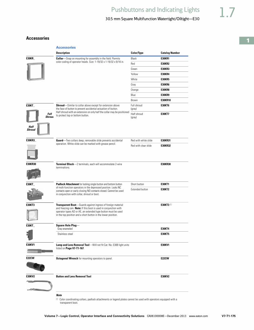
Volume 7—Logic Control, Operator Interface and Connectivity Solutions CA08100008E—December 2013 www.eaton.com V7-T1-175
1
1
1
1
1
1
1
1
1
1
1
1
1
1
1
1
1
1
1
1
1
1
1
1
1
1
1
1
1
1
1.7Pushbuttons and Indicating Lights
30.5 mm Square Multifunction Watertight/Oiltight—E30
Accessories
Accessories
Note1 Color coordinating collars, padlock attachments or legend plates cannot be used with operators equipped with a
transparent boot.
Description Color/Type Catalog Number
Collar—Snap on mounting for assembly in the field. Permits color coding of operator heads. Size: 1-19/32 x 1-19/32 x 9/16 in.
Black E30KR1
Red E30KR2
Green E30KR3
Yellow E30KR4
White E30KR5
Gray E30KR6
Orange E30KR8
Blue E30KR9
Brown E30KR10
Shroud—Similar to collar above except for extension above the face of button to prevent accidental actuation of button. Half shroud with an extension on only half the collar may be positioned to protect top or bottom button.
Full shroud (gray)
E30KT6
Half shroud (gray)
E30KT7
Guard—Two collars deep, removable slide prevents accidental operation. White slide can be marked with grease pencil.
Red with white slide E30KR31
Red with clear slide E30KR32
Terminal Block—2 terminals, each will accommodate 2-wire terminations.
E30KR30
Padlock Attachment for locking single button and bottom button of multi-function operators in the depressed position. Locks NC contacts open or early closing NO contacts closed. Cannot be used in conjunction with collar, shroud or boot.
Short button E30KT1
Extended button E30KT2
Transparent Boot—Guards against ingress of foreign material and freezing rain. Note: If this boot is used in conjunction with operator types AD or AE, an extended type button must be used in the top position and a short button in the lower position.
E30KT3 1
Square Hole Plug— Gray enameled E30KT4
Stainless steel E30KT5
Lamp and Lens Removal Tool—Will not fit Cat. No. E30B light units listed on Page V7-T1-167.
E30KV1
Octagonal Wrench for mounting operators to panel. E22CW
Button and Lens Removal Tool E30KV2
E30KR_
FullShroud
HalfShroud
E30KT_
E30KR3_
E30KR30
E30KT_
E30KT3
E30KT_
E30KV1
E22CW
E30KV2
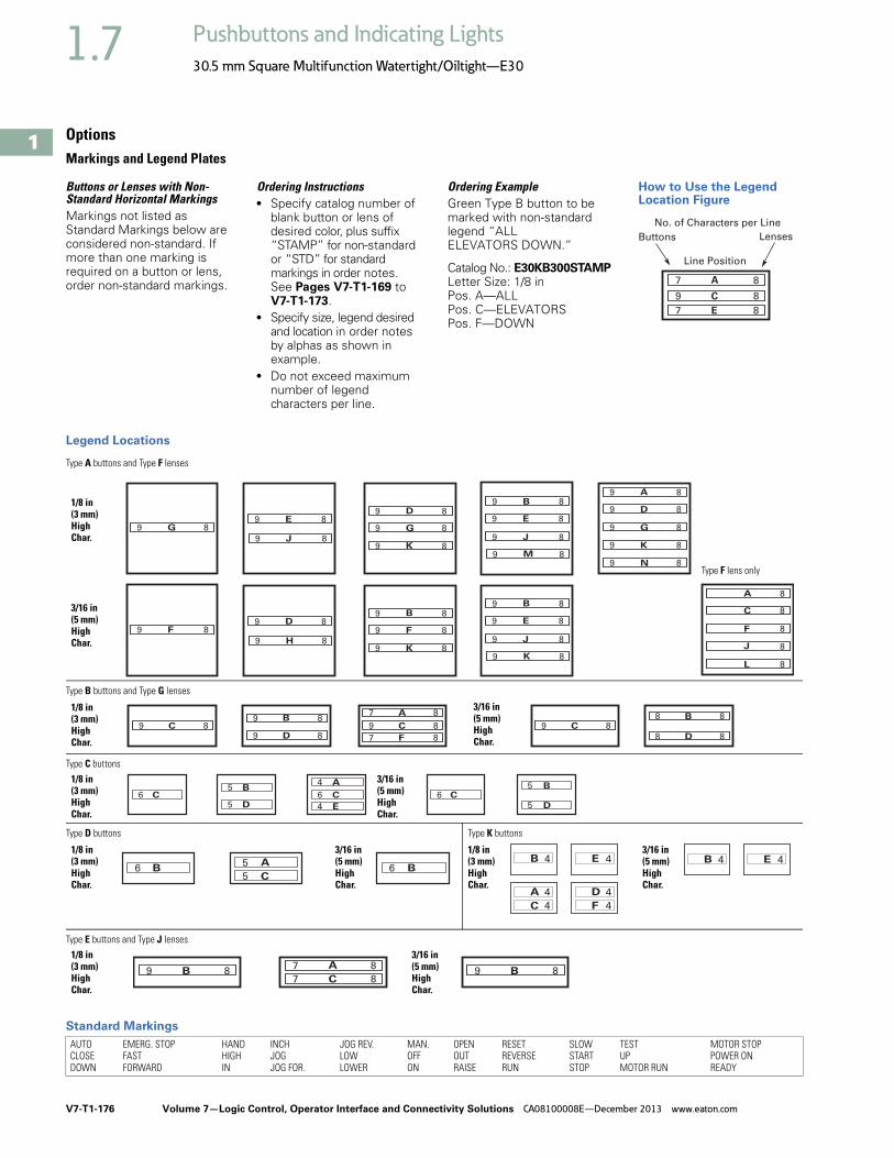
V7-T1-176 Volume 7—Logic Control, Operator Interface and Connectivity Solutions CA08100008E—December 2013 www.eaton.com
1
1
1
1
1
1
1
1
1
1
1
1
1
1
1
1
1
1
1
1
1
1
1
1
1
1
1
1
1
1
1.7 Pushbuttons and Indicating Lights
30.5 mm Square Multifunction Watertight/Oiltight—E30
OptionsMarkings and Legend Plates
Buttons or Lenses with Non-Standard Horizontal MarkingsMarkings not listed as Standard Markings below are considered non-standard. If more than one marking is required on a button or lens, order non-standard markings.
Ordering Instructions● Specify catalog number of
blank button or lens of desired color, plus suffix “STAMP” for non-standard or “STD” for standard markings in order notes. See Pages V7-T1-169 to V7-T1-173.
● Specify size, legend desired and location in order notes by alphas as shown in example.
● Do not exceed maximum number of legend characters per line.
Ordering ExampleGreen Type B button to be marked with non-standard legend “ALL ELEVATORS DOWN.”
Catalog No.: E30KB300STAMPLetter Size: 1/8 inPos. A—ALLPos. C—ELEVATORSPos. F—DOWN
How to Use the Legend Location Figure
Legend Locations
Standard Markings
Buttons Lenses
Line Position
7
9
A
C
E7
8
8
8
No. of Characters per Line
AUTOCLOSEDOWN
EMERG. STOPFASTFORWARD
HANDHIGHIN
INCHJOGJOG FOR.
JOG REV.LOWLOWER
MAN.OFFON
OPENOUTRAISE
RESETREVERSERUN
SLOWSTARTSTOP
TESTUPMOTOR RUN
MOTOR STOPPOWER ONREADY
7
7
A
C
8
89 9B B8 8
5
56
A
CB6 B
4
4
A
C
4B 4E
4
4
D
F
4E4B
54 5
56 6
BA B
DC C
E D4 5
6 C
97 8
99 9
BA B
DC C
F D7 8
88 8
88 8
8 8
9 C 8
9
99
99
99
9
9
D
AB
EG
DE
J
G
K
N
G
KJ
M9
9
9
99
9
8
88
88
88
8
8
8
8
8
88
8
99
99
9
9
9
BB
DF
E
H
F
KJ
K9
9
9
88
88
8
8
8
88
8
A
C
L
F
J
8
8
8
8
8
1/8 in(3 mm)HighChar.
Type A buttons and Type F lenses
Type B buttons and Type G lenses
1/8 in(3 mm)HighChar.
Type C buttons
1/8 in(3 mm)HighChar.
Type D buttons
1/8 in(3 mm)HighChar.
Type K buttons
Type E buttons and Type J lenses
1/8 in(3 mm)HighChar.
1/8 in (3 mm)HighChar.
3/16 in(5 mm)HighChar.
Type F lens only
3/16 in(5 mm)HighChar.
3/16 in(5 mm)HighChar.
3/16 in(5 mm)HighChar.
3/16 in(5 mm)HighChar.
3/16 in(5 mm)HighChar.

Volume 7—Logic Control, Operator Interface and Connectivity Solutions CA08100008E—December 2013 www.eaton.com V7-T1-177
1
1
1
1
1
1
1
1
1
1
1
1
1
1
1
1
1
1
1
1
1
1
1
1
1
1
1
1
1
1
1.7Pushbuttons and Indicating Lights
30.5 mm Square Multifunction Watertight/Oiltight—E30
Legend Arrangements and Legend Locations
Legend Plates E30KN76 or KN76B
Maximum Number and Size of Permissible Legend Characters of Custom Stamped Legend Plates
Legend plates E30KM1 or KM11
Legend plates E30KM4 or KM14
Legend plates E30KM2 or KM12
Legend plates E30KM5 or KM15
Legend plates E30KM3 or KM13
Legend plates E30KM6 or KM16
H
G
KB
JA
D M
C L
B F M
G
B
A
F
E
M
L
H
B
M
M
K
D
B F
E
F
F
A
B
B
D
C
C
D
B F
A
B
B
TypeNo.ofLines
Size and Maximum Number of Characters Per LineOne Span Two Span Three Span3/32 in(2.5 mm)
1/8 in(3 mm)
3/16 in(5 mm)
3/32 in(2.5 mm)
1/8 in(3 mm)
3/16 in(5 mm)
3/32 in(2.5 mm)
1/8 in(3 mm)
3/16 in(5 mm)
Standard 1 13 10 10 30 22 22 47 34 34
Large 1 13 10 10 30 23 23 47 36 36
2 13 10 10 30 23 23 47 36 36
Characters available for non-standard markings3/32 in (2.5 mm)—1/8 in (3 mm)—3/16 in (5 mm)
A B C D E F G H I J K L M N O P Q R S T U V W X Y Z . / — , 1 2 3 4 5 6 7 8 9 0
Legend platesE30KN76 or KN76B1/8 in character size only with a maximum of six characters.
LINE B
LIN E
A
LIN E
C

V7-T1-178 Volume 7—Logic Control, Operator Interface and Connectivity Solutions CA08100008E—December 2013 www.eaton.com
1
1
1
1
1
1
1
1
1
1
1
1
1
1
1
1
1
1
1
1
1
1
1
1
1
1
1
1
1
1
1.7 Pushbuttons and Indicating Lights
30.5 mm Square Multifunction Watertight/Oiltight—E30
Buttons or Lenses with Non-Standard Vertical Markings
Ordering Instructions● Specify catalog number
of blank button or lens of desired color, selected from listings on Pages V7-T1-169 to V7-T1-173.
● Specify size, legend desired, location and state “vertically marked” in order notes.
Note: Specify either 1/8 or 3/16 in (3.2 or 4.8 mm) character height. Do not exceed maximum number of characters as outlined in table below.
Ordering Example:Green Type K button to be marked with “RUN” “ON.”
Catalog No.: E30KK20STAMPLetter Size: 3/16 in (4.8 mm)Vertically MarkedPos. B—RUNPos. E—ON
Legend PlatesLegend plates for Type E30 compact pushbutton and indicating light operators hook directly onto the operator and are clamped in place when the operator locking nut behind the panel is secured.
Two and three span plates are designed for use where two or more operators are mounted adjacent to each other on minimum horizontal mounting centers. These legend plates mount in the same manner as single span units.
Maximum Number of Characters
Description TypeMaximum Number of Characters1/8 in (3.2 mm) 3/16 in (4.8 mm)
Buttons A 7 5
B 7 5
C 4 3
D 5 3
E 7 5
Lenses F 7 5
G 7 5
J 7 5
K 3 2
When Ordering Legend Plates with Markings● Catalog number of blank
legend plate● Insert the following in
order notes:● Legends required● Size of characters—
3/32, 1/8, 3/16 in (2.4, 3.2, 4.8 mm)
● Positions of legends on one line standard and two line large legend plates by alphas as shown in sketches on following page.
Ordering Example:Three span legend plate to be marked “MASTER CONTROL”, “STATION A” and “STATION B.”
Catalog No.: E30KM3STAMPLetter Size: 1/8 in (3.2 mm)Pos. C—MASTER CONTROLPos. B—STATION APos. F—STATION B
Blank Legend Plates and Legend Plates with Markings
TypeOne SpanCatalog Number
Black
Standard E30KM1
Large E30KM4
Standard— One Span
Large—One Span

Volume 7—Logic Control, Operator Interface and Connectivity Solutions CA08100008E—December 2013 www.eaton.com V7-T1-179
1
1
1
1
1
1
1
1
1
1
1
1
1
1
1
1
1
1
1
1
1
1
1
1
1
1
1
1
1
1
1.7Pushbuttons and Indicating Lights
30.5 mm Square Multifunction Watertight/Oiltight—E30
Replacement Parts
Replacement Light Units for E30 Components
Replacement Lamps for E30 Illuminated Operators
Replacement Lamps—Incandescent and LED
Note1 E30 blue LED bulbs may not provide sufficient intensity for some applications.
VoltageAC and DC
Part Numbers—Receptacles without LampsSingleIndicating Light
DualIndicating Light
Single LightSingle Pushbutton
Single LightDual Pushbutton
Dual LightDual Pushbutton
Full Voltage Type
6V 57-2579-3A 57-2568A 57-2568A 57-2579-3A 57-2567
12V 57-2579-3A 57-2568A 57-2568A 57-2579-3A 57-2567
18/24V 57-2579-3A 57-2568A 57-2568A 57-2579-3A 57-2567
28V 57-2579-3A 57-2568A 57-2568A 57-2579-3A 57-2567
32V 57-2579-3A 57-2568-2A 57-2568-2A — 57-2567
48V 57-2579-3A 57-2568A 57-2568A 57-2579-3A 57-2567
120V 57-2579-3A 57-2568A 57-2568A 57-2579-3A 57-2567
Transformer Type
120V 42-2672A 42-2663A 42-2663A 42-2671A 42-2664A
208V 42-2672-2A 42-2663-2A 42-2663-2A 42-2671-2A 42-2664-2A
240V 42-2672-3A 42-2663-3A 42-2663-3A 42-2671-3A 42-2664-3A
380V 42-2672-4A 42-2663-4A 42-2663-4A 42-2671-4A 42-2664-4A
480V 42-2672-5A 42-2663-5A 42-2663-5A 42-2671-5A 42-2664-5A
600V 42-2672-6A 42-2663-6A 42-2663-6A 42-2671-6A 42-2664-6A
Description and Part Numbers—Related Parts
Inner lens 28-1008 28-1010 28-1010 28-1010 28-1010
Retaining nut 15-1885 15-1885 15-1885 15-1885 15-1885
Gasket 16-2092 16-2092 16-2092 16-2092 16-2092
Locking ring 52-1116 52-1116 52-1116 52-1116 52-1116
Mfg. Lamp Type Voltage Base Style Application Part Number
6PSB 6V T2 slide E30 transformer and full voltage 28-1022
12PSB 12V T2 slide E30 full voltage 28-1025
24PSB 24V T2 slide E30 full voltage 28-1026
28PSB 28V T2 slide E30 full voltage 28-1027
48PSB 48V T2 slide E30 full voltage 28-1028
60PSB 60V T2 slide E30 full voltage 28-1598
120PSB 120V T2 slide E30 full voltage 28-1029
#259 6.3V T3-1/4 wedge E30 single transformer 28-949
LampVoltage
Incandescent Lamps LED Lamps
Manufacturer’sPart Number
BaseStyle
Eaton’sPart Number
Eaton’s Part NumberRed Green Yellow Blue 1
6 6PSB T2 slide 28-1022 35-1523 35-1523-2 35-1523-3 35-1523-17
12 12PSB T2 slide 28-1025 35-1523-11 35-1523-12 35-1523-13 35-1523-18
24 24PSB T2 slide 28-1026 35-1523-4 35-1523-5 35-1523-6 35-1523-19
28 28PSB T2 slide 28-1027 35-1523-4 35-1523-5 35-1523-6 35-1523-19
48 48PSB T2 slide 28-1028 35-1523-14 35-1523-15 35-1523-16 35-1523-20
120 120PSB T2 slide 28-1029 35-1523-7 35-1523-8 35-1523-9 35-1523-21

V7-T1-180 Volume 7—Logic Control, Operator Interface and Connectivity Solutions CA08100008E—December 2013 www.eaton.com
1
1
1
1
1
1
1
1
1
1
1
1
1
1
1
1
1
1
1
1
1
1
1
1
1
1
1
1
1
1
1.7 Pushbuttons and Indicating Lights
30.5 mm Square Multifunction Watertight/Oiltight—E30
Technical Data and Specifications
Operator Specifications
Reliability Nibs
Electrical Ratings
Contact Blocks
● UL A600/P300 nominal connect 10A● 1NO, 1NC, 2NO, 2NC, 1NO-1NC, early make, late break and
overlapping configurations● Mechanical positive drive operation on NC contacts● Palladium alloy contact for logic level or highly corrosive
environments
Maximum Ratings for Logic Level and Hostile Atmosphere Application Light Unit
Note1 Logic level contact blocks are UL A600/P500 rated per table above.
Description Specification
Climate Conditions
Operating –20° to 150°F (–29° to 65°C)
Terminals
Light units Terminals are saddle clamp type for 2 stranded or solid wires up to 12 AWG (4.0 mm2)Torque—7 lb-in (0.8 Nm)
Contact block Terminals are saddle clamp type for 2 stranded or solid wires up to 12 AWG (4.0 mm2)Torque—7 lb-in (0.8 Nm)
Materials
Operator Zinc base die casting with a copper-nickel-chrome plated finishWithstands the 200 hr. salt spray test in accordance with MIL Spec. QQ-M-151A and NEMA 4X testing.
Internal parts Including shafts, washers and springs, are made of stainless steel
Buttons and lenses Colorfast, wear resistant, molded acetal resin
Contact blocks Made of molded, heat resistant, mineral filled phenolicContact block plungers are molded of nylon filled phenolicContacts are silver
Reliability nibs These nibs combine a scrubbing action with high pressure density when the contacts are closedThey push through particles and films found on contact surfaces in industrial environmentsReliability nibs self-adjust to the application—dry circuit, normal or heavy-duty
Meet or Exceed NEMA Contact Rating Designation A600 and P300Vac A600 Vdc P300
Description 120V 240V 480V 600V 24/28V 125V 250V
Make and emergencyinterrupting capacity (Amps)
60 30 15 12 5.73 1.1 0.55
Normal load break (Amps) 6 3 1.5 1.2 5.73 1.1 0.55
Continuous current (Amps) 10 10 10 10 5 5 5
Heavy-DutyDry Circuit Medium Duty
Description Specification
Maximum amperes 0.5A 1
Maximum volts 120 Vac/Vdc
Description Specification
Bulbs—Average Life
Transformer type 20,000 hrs.
Resistor/direct voltage type 2,500 hrs. min. at rated voltage
LED 60,000 to 100,000 hrs.
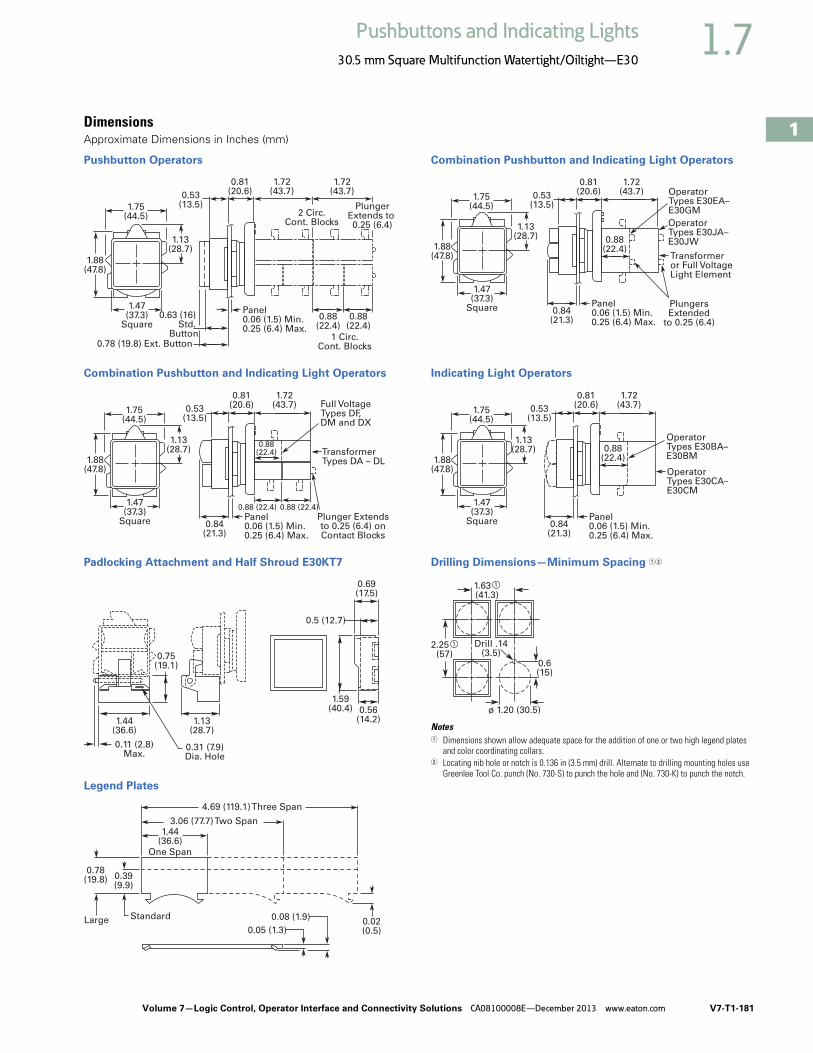
Volume 7—Logic Control, Operator Interface and Connectivity Solutions CA08100008E—December 2013 www.eaton.com V7-T1-181
1
1
1
1
1
1
1
1
1
1
1
1
1
1
1
1
1
1
1
1
1
1
1
1
1
1
1
1
1
1
1.7Pushbuttons and Indicating Lights
30.5 mm Square Multifunction Watertight/Oiltight—E30
DimensionsApproximate Dimensions in Inches (mm)
Pushbutton Operators
Combination Pushbutton and Indicating Light Operators
Padlocking Attachment and Half Shroud E30KT7
Legend Plates
Combination Pushbutton and Indicating Light Operators
Indicating Light Operators
Drilling Dimensions—Minimum Spacing 12
Notes1 Dimensions shown allow adequate space for the addition of one or two high legend plates
and color coordinating collars.2 Locating nib hole or notch is 0.136 in (3.5 mm) drill. Alternate to drilling mounting holes use
Greenlee Tool Co. punch (No. 730-S) to punch the hole and (No. 730-K) to punch the notch.
1.75(44.5)
0.53(13.5)
0.81(20.6)
1.72(43.7)
1.72(43.7)
1.47(37.3)
Square0.88
(22.4)0.88
(22.4)
1.13(28.7)
1.88(47.8)
Panel0.06 (1.5) Min.0.25 (6.4) Max.
0.78 (19.8) Ext. Button
0.63 (16) Std.
Button 1 Circ.Cont. Blocks
2 Circ.Cont. Blocks
PlungerExtends to 0.25 (6.4)
0.88(22.4)
0.88 (22.4) 0.88 (22.4)
Full VoltageTypes DF, DM and DX
Plunger Extendsto 0.25 (6.4) onContact Blocks
TransformerTypes DA – DL
1.75(44.5)
0.53(13.5)
0.84(21.3)
0.81(20.6)
1.72(43.7)
1.47(37.3)
Square
1.13(28.7)
1.88(47.8)
Panel0.06 (1.5) Min.0.25 (6.4) Max.
0.69(17.5)
1.13(28.7)
0.31 (7.9)Dia. Hole
0.5 (12.7)
0.56(14.2)
1.59(40.4)
0.75(19.1)
1.44(36.6)
0.11 (2.8)Max.
1.44(36.6)
0.02(0.5)
0.78(19.8) 0.39
(9.9)
Standard
3.06 (77.7) Two Span
0.05 (1.3)
0.08 (1.9)
One Span
4.69 (119.1) Three Span
Large
0.88(22.4)
OperatorTypes E30JA–E30JW
OperatorTypes E30EA–E30GM
PlungersExtended
to 0.25 (6.4)
Transformeror Full VoltageLight Element
1.75(44.5)
0.53(13.5)
0.84(21.3)
0.81(20.6)
1.72(43.7)
1.47(37.3)
Square
1.13(28.7)
1.88(47.8)
Panel0.06 (1.5) Min.0.25 (6.4) Max.
1.75(44.5)
0.53(13.5)
0.84(21.3)
0.81(20.6)
1.72(43.7)
1.47(37.3)
Square
1.13(28.7)
1.88(47.8)
0.88(22.4)
Panel0.06 (1.5) Min.0.25 (6.4) Max.
OperatorTypes E30BA–E30BM
OperatorTypes E30CA–E30CM
1.63 a
(41.3)
2.25 a
(57)0.6(15)
Drill .14(3.5)
ø 1.20 (30.5)
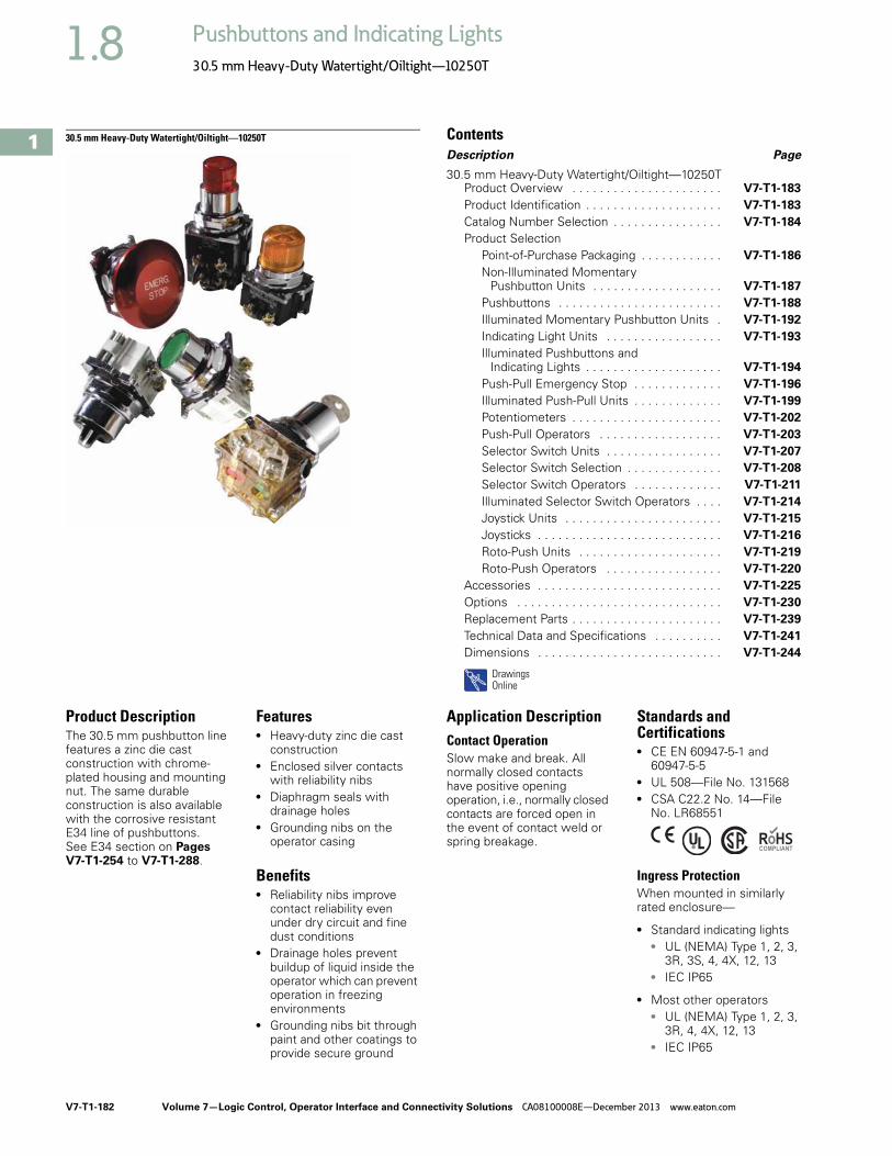
V7-T1-182 Volume 7—Logic Control, Operator Interface and Connectivity Solutions CA08100008E—December 2013 www.eaton.com
1
1
1
1
1
1
1
1
1
1
1
1
1
1
1
1
1
1
1
1
1
1
1
1
1
1
1
1
1
1
1.8 Pushbuttons and Indicating Lights
30.5 mm Heavy-Duty Watertight/Oiltight—10250T
30.5 mm Heavy-Duty Watertight/Oiltight—10250T ContentsDescription Page
30.5 mm Heavy-Duty Watertight/Oiltight—10250TProduct Overview . . . . . . . . . . . . . . . . . . . . . . V7-T1-183
Product Identification . . . . . . . . . . . . . . . . . . . . V7-T1-183
Catalog Number Selection . . . . . . . . . . . . . . . . V7-T1-184
Product Selection Point-of-Purchase Packaging . . . . . . . . . . . . V7-T1-186
Non-Illuminated Momentary Pushbutton Units . . . . . . . . . . . . . . . . . . . V7-T1-187
Pushbuttons . . . . . . . . . . . . . . . . . . . . . . . . V7-T1-188
Illuminated Momentary Pushbutton Units . V7-T1-192
Indicating Light Units . . . . . . . . . . . . . . . . . V7-T1-193
Illuminated Pushbuttons and Indicating Lights . . . . . . . . . . . . . . . . . . . . V7-T1-194
Push-Pull Emergency Stop . . . . . . . . . . . . . V7-T1-196
Illuminated Push-Pull Units . . . . . . . . . . . . . V7-T1-199
Potentiometers . . . . . . . . . . . . . . . . . . . . . . V7-T1-202
Push-Pull Operators . . . . . . . . . . . . . . . . . . V7-T1-203
Selector Switch Units . . . . . . . . . . . . . . . . . V7-T1-207
Selector Switch Selection . . . . . . . . . . . . . . V7-T1-208
Selector Switch Operators . . . . . . . . . . . . . V7-T1-211
Illuminated Selector Switch Operators . . . . V7-T1-214
Joystick Units . . . . . . . . . . . . . . . . . . . . . . . V7-T1-215
Joysticks . . . . . . . . . . . . . . . . . . . . . . . . . . . V7-T1-216
Roto-Push Units . . . . . . . . . . . . . . . . . . . . . V7-T1-219
Roto-Push Operators . . . . . . . . . . . . . . . . . V7-T1-220
Accessories . . . . . . . . . . . . . . . . . . . . . . . . . . . V7-T1-225
Options . . . . . . . . . . . . . . . . . . . . . . . . . . . . . . V7-T1-230
Replacement Parts . . . . . . . . . . . . . . . . . . . . . . V7-T1-239
Technical Data and Specifications . . . . . . . . . . V7-T1-241
Dimensions . . . . . . . . . . . . . . . . . . . . . . . . . . . V7-T1-244
DrawingsOnline
Product DescriptionThe 30.5 mm pushbutton line features a zinc die cast construction with chrome-plated housing and mounting nut. The same durable construction is also available with the corrosive resistant E34 line of pushbuttons. See E34 section on Pages V7-T1-254 to V7-T1-288.
Features● Heavy-duty zinc die cast
construction● Enclosed silver contacts
with reliability nibs● Diaphragm seals with
drainage holes● Grounding nibs on the
operator casing
Benefits● Reliability nibs improve
contact reliability even under dry circuit and fine dust conditions
● Drainage holes prevent buildup of liquid inside the operator which can prevent operation in freezing environments
● Grounding nibs bit through paint and other coatings to provide secure ground
Application DescriptionContact OperationSlow make and break. All normally closed contacts have positive opening operation, i.e., normally closed contacts are forced open in the event of contact weld or spring breakage.
Standards and Certifications● CE EN 60947-5-1 and
60947-5-5● UL 508—File No. 131568● CSA C22.2 No. 14—File
No. LR68551
Ingress Protection When mounted in similarly rated enclosure—
● Standard indicating lights● UL (NEMA) Type 1, 2, 3,
3R, 3S, 4, 4X, 12, 13 ● IEC IP65
● Most other operators● UL (NEMA) Type 1, 2, 3,
3R, 4, 4X, 12, 13● IEC IP65

Volume 7—Logic Control, Operator Interface and Connectivity Solutions CA08100008E—December 2013 www.eaton.com V7-T1-183
1
1
1
1
1
1
1
1
1
1
1
1
1
1
1
1
1
1
1
1
1
1
1
1
1
1
1
1
1
1
1.8Pushbuttons and Indicating Lights
30.5 mm Heavy-Duty Watertight/Oiltight—10250T
Product OverviewReliability NibsEaton’s contact blocks feature enclosed silver contacts with pointed “reliability nibs” for reliable performance from logic level up to 600V. To ensure reliable switching, nibs bite through oxide which can form on silver contacts, eliminating the need for expensive logic level blocks for most applications.
Reliability Nibs
Reliability nibs improve performance in dry circuit, corrosive, fine dust and other contaminated atmospheres. Under normal environmental conditions, the minimum operational voltage is 5V and the minimum operational current is 1 mA, AC/DC. For operation under a wider range of environmental conditions, logic level contact blocks with inert palladium tipped contacts are recommended.
Grounding Nibs10250T line operators have “grounding nibs”—four metal points on the operator casting designed to bite through most paints and other coatings on metal panels to enhance the ground connection when the operator is securely tightened.
Grounding Nibs
Product Identification
30.5 mm Heavy-Duty Watertight/Oiltight—10250T Series
Dry Circuit
Medium Duty
Heavy-Duty
GroundingNibs
Mounting Nut Legend Plate Operator
Terminal Clamps Shipped Ready to Wire
Stackable Contact Blocks up to 12 Circuits
per Operator
Color Coded PlungersRed = NC Green = NO
Diaphragm Seal with Drainage Holes
Liquid DrainageEaton’s pushbutton operators offer front of panel drainage via holes in the operator bushing. Hidden from view by the mounting nut, these holes prevent buildup of liquid inside the operator, which can prevent operation in freezing environments. The holes also provide a route for escaping liquid in high pressure washdowns, effectively relieving pressure from the internal diaphragm seal, ensuring reliable sealing in applications even beyond NEMA 4.
Diaphragm Seal
Foam NeoprenePanel Sealing Gasket
Drainage Hole
Drainage Hole
FlexibleDiaphragm
StainlessSteel
OperatingSpring
Mounting Nut
ColorfastMoldedButton

V7-T1-184 Volume 7—Logic Control, Operator Interface and Connectivity Solutions CA08100008E—December 2013 www.eaton.com
1
1
1
1
1
1
1
1
1
1
1
1
1
1
1
1
1
1
1
1
1
1
1
1
1
1
1
1
1
1
1.8 Pushbuttons and Indicating Lights
30.5 mm Heavy-Duty Watertight/Oiltight—10250T
Catalog Number SelectionCatalog Number Selection is for illustrative purposes only and not to be used to create new catalog numbers.
Non-Illuminated Pushbuttons
Illuminated and Non-Illuminated Push-Pulls
Note1 Add X at end of catalog number to receive parts assembled from factory.
10250T 10 1 – 1 1
Operator10 = Flush11 = Extended12 = 40 mm mushroom17 = 65 mm mushroom50 = 1/2 shroud vertical mount51 = 1/2 shroud horizontal mount
CircuitBlank = Operator only
1 = 1NO-1NC2 = 2NO3 = 2NC
51 = 1NC53 = 1NO
Button Color1 = Black2 = Red3 = Green4 = Yellow
5 = Gray6 = White8 = Blue9 = Orange
10250T 5 63 C47 – 1 1
CircuitBlank = Operator only
1 = 1NO-1NC2 = 2NO3 = 2NC
51 = 1NC53 = 1NOIncandescent
Light UnitLED
Light UnitBlank = Non-illuminated
89 = 24V/XFR63 = 120V/XFR64 = 208V/XFR65 = 240V/XFR82 = 277V/XFR66 = 380V/XFR67 = 480V/XFR68 = 600V/XFR69 = 6V/FV70 = 12V/FV79 = 24V/FV83 = 32V/FV80 = 120V/RES81 = 240V/RES
Blank = Non-illuminated89L = 24V/XFR63L = 120V/XFR64L = 208V/XFR65L = 240V/XFR82L = 277V/XFR66L = 380V/XFR67L = 480V/XFR68L = 600V/XFR97L = Full voltage
Non-illuminated IlluminatedButton Incandescent LED Lens Type
B60 = Black 40 mmB62 = Red 40 mmB63 = Red 40 mm—“E” STOPB61 = Green 40 mmB64 = Blue 40 mmJ60 = Black 65 mmJ62 = Red 65 mmJ63 = Red 65 mm—“E” STOPJ61 = Green 65 mmJ64 = Yellow 65 mm
C47 =C53 =C48 =C49 =C50 =C51 =C52 =C57 =C63 =C58 =C59 =C64 =C60 =C61 =C62 =C65 =C66 =C67 =
RD =ED =GD =LD =AD =
WD =— =RS =ES =GS =LS =AS =YS =
WS =— =RH =GH =AH =
Red 40 mmRed 40 mm—“E” STOPGreen 40 mmBlue 40 mmAmber 40 mmWhite 40 mmClear 40 mmRed side lightRed side light—“E” STOPGreen side lightBlue side lightAmber side lightYellow side lightWhite side lightClear side lightRed heavy-dutyGreen heavy-dutyAmber heavy-duty
LED VoltageBlank = Non-illuminatedBlank = Incandescent
06 = 6 Vac/Vdc12 = 12 Vac/Vdc24 = 24 Vac/Vdc48 = 48 Vac/Vdc60 = 60 Vac/Vdc2A = 120 Vac2D = 120 Vdc
Operator5 = Two-position maintained4 = Three-position mom push-mom pull9 = Three-position mt push-mom pull
10 = Three-position mom push-mom pull

Volume 7—Logic Control, Operator Interface and Connectivity Solutions CA08100008E—December 2013 www.eaton.com V7-T1-185
1
1
1
1
1
1
1
1
1
1
1
1
1
1
1
1
1
1
1
1
1
1
1
1
1
1
1
1
1
1
1.8Pushbuttons and Indicating Lights
30.5 mm Heavy-Duty Watertight/Oiltight—10250T
Catalog Number Selection is for illustrative purposes only and not to be used to create new catalog numbers.
Illuminated Pushbuttons
Standard Indicating Lights, PresTest and Master Test
Note1 Add X at end of catalog number to receive parts assembled from factory.
10250T 416 C21 – 1 1
CircuitBlank = Operator only
1 = 1NO-1NC2 = 2NO3 = 2NC
51 = 1NC53 = 1NO
Incandescent Lens Color LED Lens ColorC21 = RedC22 = GreenC23 = YellowC26 = WhiteC24 = BlueC43 = AmberC25 = Clear
RD = RedGD = GreenYD = Yellow
WD = WhiteLD = BlueAD = Amber
LED VoltageBlank = Incandescent
06 = 6 Vac/Vdc12 = 12 Vac/Vdc24 = 24 Vac/Vdc48 = 48 Vac/Vdc60 = 60 Vac/Vdc2A = 120 Vac2D = 120 Vdc
Incandescent Light Unit LED Light Unit416 = 24V/XFR411 = 120V/XFR412 = 240V/XFR419 = 277V/XFR413 = 380V/XFR414 = 480V/XFR415 = 600V/XFR473 = 6V/FV474 = 12V/FV476 = 24V/FV477 = 32V/FV478 = 48V/FV471 = 120V/RES472 = 240V/RES
397L = Full voltage416L = 24V/XFR411L = 120V/XFR412L = 240V/XFR419L = 277V/XFR413L = 380V/XFR414L = 480V/XFR415L = 600V/XFR
LED VoltageBlank = Incandescent
06 = 6 Vac/Vdc12 = 12 Vac/Vdc24 = 24 Vac/Vdc48 = 48 Vac/Vdc60 = 60 Vac/Vdc2A = 120 Vac2D = 120 Vdc
Plastic Glass Lens Color Plastic Glass Lens ColorStandard/Master—Incandescent Standard/Master/PresTest—LED
C1N =C2N =C3N =C6N =C4N =
C19N =C5N =
C7N =C8N =
— =C12N =C10N =
C9N =C11N =
RedGreenYellowWhiteBlueAmberClear
RP =GP =YP =
WP =LP =AP =
RG =GG =— =
WG =LG =AG =
RedGreenYellowWhiteBlueAmber
PresTest—IncandescentC21 =C22 =C23 =C26 =C24 =C43 =C25 =
C13N =C14N =
— =C18N =C16N =C15N =C17N =
RedGreenYellowWhiteBlueAmberClear
Light Unit TypeStandard—Incandescent Standard—LED
181N =182N =198N =183N =184N =185N =203N =204N =206N =207N =208N =201N =202N =226N =227N =
120V/XFR240V/XFR277V/XFR380V/XFR480V/XFR600V/XFR6V/FV12V/FV24V/FV32V/FV48V/FV120V/RES240V/RES120V/neon240V/neon
181L =182L =198L =183L =184L =185L =197L =
120V/XFR240V/XFR277V/XFR380V/XFR480V/XFR600V/XFRFull voltage
PresTest—LED221L =222L =223L =224L =225L =297L =
120V/XFR240V/XFR380V/XFR480V/XFR600V/XFRFull voltage
PresTest—Incandescent221N =222N =223N =224N =225N =232N =233N =235N =238N =239N =231N =240N =
120V/XFR240V/XFR380V/XFR480V/XFR600V/XFR6V/FV12V/FV24V/FV32V/FV48V/FV120V/RES240V/RES
Master Test—Incandescent187N =189N =
120V/XFR240 Vac—SS
10250T 203N C1N 1
LED VoltageBlank = Incandescent
06 = 6 Vac/Vdc12 = 12 Vac/Vdc24 = 24 Vac/Vdc48 = 48 Vac/Vdc60 = 60 Vac/Vdc2A = 120 Vac

V7-T1-186 Volume 7—Logic Control, Operator Interface and Connectivity Solutions CA08100008E—December 2013 www.eaton.com
1
1
1
1
1
1
1
1
1
1
1
1
1
1
1
1
1
1
1
1
1
1
1
1
1
1
1
1
1
1
1.8 Pushbuttons and Indicating Lights
30.5 mm Heavy-Duty Watertight/Oiltight—10250T
Product SelectionPoint-of-Purchase Packaging
10250T Point-of-Purchase Packaged Pilot Devices
Product Description Catalog Number
Emergency Stop Operators
Red non-illuminatedpush-pull
1NO-1NC contact block. Also includes two square engraved legend plates: EMERG. STOP and STOP.
10250T5B62-1-POP
Red mushroompushbutton
1NO-1NC contact block. Also includes two square engraved legend plates: EMERG. STOP and STOP.
10250T32R-POP
Red jumbomushroom pushbutton
Engraved EMERG. STOP with 1NO-1NC contact block. 10250T33-POP
Momentary Pushbuttons
Black flushpushbutton
1NO-1NC contact block. Also includes two square engraved legend plates: START and JOG.
10250T30B-POP
Red extendedpushbutton
1NO-1NC contact block. Also includes one square engraved legend plate: STOP.
10250T31R-POP
Indicating Lights
Red indicating light Full voltage 24 Vac/Vdc with two extra lenses: Green and amber.Also includes two square engraved legend plates: RUN and JOG.
10250T206NC1N-POP
Red indicating light Resistor 120 Vac/Vdc with two extra lenses: Green and Amber.Also includes one square engraved legend plate: RUN and JOG.
10250T34R-POP
Illuminated Pushbuttons
Red illuminatingpushbutton
Full voltage 24 Vac/Vdc with 1NO-1NC contact block and two extra lenses: Green and amber. Also includes one square engraved legend plate: POWER ON.
10250T476C21-1-POP
Red illuminatingpushbutton
Resistor 120 Vac/Vdc with 1NO-1NC contact block and two extra lenses: Green and amber. Also includes one square engraved legend plate: POWER ON.
10250T411C21-1-POP
Selector Switches
Black knob two-position selector switch
1NO-1NC contact block. Also includes three square engraved legend plates: OFF/ON, HAND/AUTO and RUN/JOG.
10250T20KB-POP
Black knob three-position selector switch
2NO-2NC contact blocks. Also includes 1 square engraved legend plate: HAND/OFF/AUTO.
10250T22KB-POP
Black knob three-position selector switch
1NO-1NC contact block. Also includes legend plate: HAND/OFF/AUTO
10250T21KB-POP
Point-of-Purchase Packaged Pilot Device

Volume 7—Logic Control, Operator Interface and Connectivity Solutions CA08100008E—December 2013 www.eaton.com V7-T1-187
1
1
1
1
1
1
1
1
1
1
1
1
1
1
1
1
1
1
1
1
1
1
1
1
1
1
1
1
1
1
1.8Pushbuttons and Indicating Lights
30.5 mm Heavy-Duty Watertight/Oiltight—10250T
Non-Illuminated Momentary Pushbutton UnitsUL (NEMA) Type 3, 3R, 4, 4X, 12, 13
Pushbutton Units—Flush, Extended, Mushroom Head or Jumbo Mushroom Head Operators
Note1 Anodized aluminum head is not suitable for use in ultraviolet light applications.
ContactType Button Color
Flush ButtonCatalog Number
Extended ButtonCatalog Number
Mushroom ButtonCatalog Number
Jumbo Mushroom 1
Catalog Number
1NO Black 10250T23B 10250T25B 10250T26B 10250T27B
Red 10250T23R 10250T112-53 10250T122-53 10250T172-53
Green 10250T23G 10250T25G 10250T26G 10250T27G
Yellow 10250T23Y 10250T25Y 10250T26Y 10250T27Y
Red—Engraved EMERG. STOP — — — 10250T17213-53
1NC Black 10250T101-51 10250T111-51 10250T121-51 10250T171-51
Red 10250T102-51 10250T25R 10250T26R 10250T27R
Green 10250T103-51 10250T113-51 10250T123-51 10250T173-51
Yellow 10250T104-51 10250T120-51 10250T124-51 10250T174-51
Red—Engraved EMERG. STOP — — — 10250T29
1NO-1NC Black 10250T30B 10250T31B 10250T32B 10250T33B
Red 10250T30R 10250T31R 10250T32R 10250T33R
Green 10250T30G 10250T31G 10250T32G 10250T33G
Yellow 10250T30Y 10250T31Y 10250T32Y 10250T33Y
Red—Engraved EMERG. STOP — — — 10250T33
2NO Black 10250T101-2 10250T111-2 10250T121-2 10250T171-2
Red 10250T102-2 10250T112-2 10250T122-2 10250T172-2
Green 10250T103-2 10250T113-2 10250T123-2 10250T173-2
Yellow 10250T104-2 10250T120-2 10250T124-2 10250T174-2
Red—Engraved EMERG. STOP — — — 10250T17213-2
2NC Black 10250T101-3 10250T111-3 10250T121-3 10250T171-3
Red 10250T102-3 10250T112-3 10250T122-3 10250T172-3
Green 10250T103-3 10250T113-3 10250T123-3 10250T173-3
Yellow 10250T104-3 10250T120-3 10250T124-3 10250T174-3
Red—Engraved EMERG. STOP — — — 10250T17213-3
Flush Button
Extended Button
Mushroom Button
Jumbo Mushroom
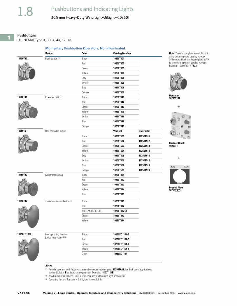
V7-T1-188 Volume 7—Logic Control, Operator Interface and Connectivity Solutions CA08100008E—December 2013 www.eaton.com
1
1
1
1
1
1
1
1
1
1
1
1
1
1
1
1
1
1
1
1
1
1
1
1
1
1
1
1
1
1
1.8 Pushbuttons and Indicating Lights
30.5 mm Heavy-Duty Watertight/Oiltight—10250T
PushbuttonsUL (NEMA) Type 3, 3R, 4, 4X, 12, 13
Momentary Pushbutton Operators, Non-illuminated
Notes1 To order operator with factory assembled extended retaining nut, 10250TA12, for thick panel applications,
add suffix letter E to listed catalog number. Example: 10250T101E.2 Anodized aluminum head is not suitable for use in ultraviolet light applications.3 Operating force—Standard = 2.4 lb; low force = 1.6 lb.
Button Color Catalog Number Note: To order complete assembled unit using one composite catalog number, add contact block and legend plate suffix to the end of operator catalog number. Example: 10250T101-1TS33
Flush button 1 Black 10250T101
Red 10250T102
Green 10250T103
Yellow 10250T104
Gray 10250T105
White 10250T106
Blue 10250T108
Orange 10250T109
Extended button Black 10250T111
Red 10250T112
Green 10250T113
Yellow 10250T120
White 10250T116
Blue 10250T118
Orange 10250T119
Half shrouded button Vertical Horizontal
Black 10250T501 10250T511
Red 10250T502 10250T512
Green 10250T503 10250T513
Yellow 10250T504 10250T514
Gray 10250T505 10250T515
White 10250T506 10250T516
Blue 10250T508 10250T518
Orange 10250T509 10250T519
Mushroom button Black 10250T121
Red 10250T122
Green 10250T123
Yellow 10250T124
Blue 10250T129
Jumbo mushroom button 2 Black 10250T171
Red 10250T172
Red (EMERG. STOP) 10250T17213
Green 10250T173
Yellow 10250T174
Low operating force—jumbo mushroom 23
Black 10250ED1164-2
Red 10250ED1164-3
Green 10250ED1164-4
Yellow 10250ED1164-5
Clear 10250ED1164
10250T10_
10250T11_
10250T5_
10250T17_
10250T12_
10250ED1164_
Operator 10250T101
Contact Block10250T1
Legend Plate 10250TS33

Volume 7—Logic Control, Operator Interface and Connectivity Solutions CA08100008E—December 2013 www.eaton.com V7-T1-189
1
1
1
1
1
1
1
1
1
1
1
1
1
1
1
1
1
1
1
1
1
1
1
1
1
1
1
1
1
1
1.8Pushbuttons and Indicating Lights
30.5 mm Heavy-Duty Watertight/Oiltight—10250T
UL (NEMA) Type 3, 3R, 4, 4X, 12, 13
Mechanically Interlocked Pushbutton Operators
Note1 NC contacts must be mounted behind lock-down mushroom head operator to ensure lockout.
Description Catalog Number
Black flush and green flush 10250TA66
Black flush and long red 10250TA67
Black flush and red mushroom head 10250TA68
Black flush and lock-down red mushroom head 10250TA69 1
Black flush and red jumbo mushroom head 10250TA76
Green flush and long red 10250TA72
Black long and long red 10250TA73
Green flush and red mushroom head 10250TA77
Green flush and black flush 10250TA75
10250TA_

V7-T1-190 Volume 7—Logic Control, Operator Interface and Connectivity Solutions CA08100008E—December 2013 www.eaton.com
1
1
1
1
1
1
1
1
1
1
1
1
1
1
1
1
1
1
1
1
1
1
1
1
1
1
1
1
1
1
1.8 Pushbuttons and Indicating Lights
30.5 mm Heavy-Duty Watertight/Oiltight—10250T
Lockout Pushbutton Operators with Padlock AttachmentsUL (NEMA) Type 3, 3R, 4, 4X, 12, 13
The following pushbutton and mushroom operators include an integral padlock attachment for applications requiring lockout/tagout of specific machine functions. They are available in styles which allow locking of a button in the down position
(stopped position) or locking a button in the up position (to prevent starting). Select the “Hand” latch type which functions as a momentary pushbutton until the operator presses the button and moves the padlock attachment into position for
locking, or choose the “Spring Loaded” latch type where the padlock attachment springs into place when the button is pressed. Units accept a customer supplied 1/4 in padlock.
Padlockable in the Down Position 1
Padlockable in the Up Position 1
NotesHand attachment must be manually moved into place for locking. Spring loaded: when operator is pressed—attachment springs into place. Must be moved manually to release button.1 Operators can be latched down without a padlock. Padlock not included.2 Jumbo mushroom heads are not recommended for use in applications where exposure to ultraviolet light exists.
Operator Type Color Latch Type Catalog Number
Flush head Red Hand 10250TA16
Mushroom head Red Hand 10250TA42
Red Spring loaded 10250TA45
Jumbo head 2 Red Hand 10250TA52
Red Spring loaded 10250TA55
Red (EMERG. STOP) Spring loaded 10250ED952
Operator Type Color Latch Type Catalog Number
Mushroom head Black Hand 10250TA41
Green Hand 10250TA43
Jumbo mushroom head 2
Black Hand 10250TA51
Green Hand 10250TA53
Yellow Hand 10250TA54
10250TA16
10250TA4_
10250TA5_

Volume 7—Logic Control, Operator Interface and Connectivity Solutions CA08100008E—December 2013 www.eaton.com V7-T1-191
1
1
1
1
1
1
1
1
1
1
1
1
1
1
1
1
1
1
1
1
1
1
1
1
1
1
1
1
1
1
1.8Pushbuttons and Indicating Lights
30.5 mm Heavy-Duty Watertight/Oiltight—10250T
Key Pushbutton OperatorUL (NEMA) Type 3, 3R, 4, 4X, 12, 13
These devices incorporate an integral locking mechanism which enables locking units in various positions (Locked Down), locking units to
prevent operation (Locked Up) or setting unit to lock when the button is pressed (Push to Lock), requiring the key to be inserted to return to
normal operation. With the key in the center position, these operators function as a normal momentary pushbutton (Free).
Replacement Keys or Dissimilar Locks for Key Operators BelowListed operators have identical locks and keys (Key Code H661) Catalog Number 10250ED824. For dissimilar lock and key combinations, see listing on Page V7-T1-212.
Replacement Keys
Key Pushbutton Operator
Latch-In, Twist-to-Release OperatorUL (NEMA) Type 3, 3R, 4, 4X, 12, 13
Operator Only with Button
Note1 Horizontal mounting available on request.
Description Catalog Number
Replacement keys (code H661)
10250ED824
Key Position and Pushbutton Operations
Key RemovalPositions
Vertical Mounting 1Catalog Number
Three-Position
Lock up Free Lock down All 10250T430
Lock up Free Lock down L and R 10250T431
Lock up Free Lock down C and R 10250T432
Two-Position
Lock up Free — L and C 10250T433
Lock up Free — L 10250T434
— Free Lock down C and R 10250T435
— Free Lock down R 10250T436
— Free Push to lock C and R 10250T437
— Free Push to lock R 10250T438
Description Catalog Number
Latch-in, twist-to-release operator with red mushroom head button 10250ED1043-4
10250T43_
L
C
R
10250ED1043-4

V7-T1-192 Volume 7—Logic Control, Operator Interface and Connectivity Solutions CA08100008E—December 2013 www.eaton.com
1
1
1
1
1
1
1
1
1
1
1
1
1
1
1
1
1
1
1
1
1
1
1
1
1
1
1
1
1
1
1.8 Pushbuttons and Indicating Lights
30.5 mm Heavy-Duty Watertight/Oiltight—10250T
Illuminated Momentary Pushbutton UnitsUL (NEMA) Type 3, 3R, 4, 4X, 12, 13
● LED or incandescent● Full voltage, resistor or transformer type ● Plastic lenses
Illuminated Pushbutton Units
Note1 For flashing module catalog number 10250TFL1, add suffix code FM to listed catalog number. Example: 10250T75RFM.
Type Voltage ColorLED/Lamp Number
Illuminated Pushbutton1NO 1NO-1NC 1NCCatalog Number Catalog Number Catalog Number
LED Lamp
Full voltage 24 Vac/Vdc Red Bayonet base
10250T397LRD24-53 10250T397LRD24-1 10250T397LRD24-51
Green 10250T397LGD24-53 10250T397LGD24-1 10250T397LGD24-51
Amber 10250T397LAD24-53 10250T397LAD24-1 10250T397LAD24-51
Yellow 10250T397LYD24-53 10250T397LYD24-1 10250T397LYD24-51
Blue 10250T397LLD24-53 10250T397LLD24-1 10250T397LLD24-51
White 10250T397LWD24-53 10250T397LWD24-1 10250T397LWD24-51
120 Vac/Vdc Red 10250T397LRD2A-53 10250T397LRD2A-1 10250T397LRD2A-51
Green 10250T397LGD2A-53 10250T397LGD2A-1 10250T397LGD2A-51
Amber 10250T397LAD2A-53 10250T397LAD2A-1 10250T397LAD2A-51
Yellow 10250T397LYD2A-53 10250T397LYD2A-2 10250T397LYD2A-51
Blue 10250T397LLD2A-53 10250T397LLD2A-1 10250T397LLD2A-51
White 10250T397LWD2A-53 10250T397LWD2A-1 10250T397LWD2A-51
Transformer 120 Vac Red 10250T411LRD06-53 10250T411LRD06-1 10250T411LRD06-51
Green 10250T411LGD06-53 10250T411LGD06-1 10250T411LGD06-51
Amber 10250T411LAD06-53 10250T411LAD06-1 10250T411LAD06-51
Yellow 10250T411LYD06-53 10250T411LYD06-1 10250T411LYD06-51
Blue 10250T411LLD06-53 10250T411LLD06-1 10250T411LLD06-51
White 10250T411LWD06-53 10250T411LWD06-1 10250T411LWD06-51
Incandescent Lamp
Full voltage 24 Vac/Vdc Red #757 10250T476C21-53 10250T476C21-1 10250T476C21-51
Green 10250T476C22-53 10250T476C22-1 10250T476C22-51
Amber 10250T476C43-53 10250T476C43-1 10250T476C43-51
Yellow 10250T476C23-53 10250T476C23-1 10250T476C23-51
Blue 10250T476C24-53 10250T476C24-1 10250T476C24-51
Clear 10250T476C25-53 10250T476C25-1 10250T476C25-51
White 10250T476C26-53 10250T476C26-1 10250T476C26-51
Resistor 120 Vac/Vdc Red 120MB 10250T471C21-53 10250T471C21-1 10250T471C21-51
Green 10250T471C22-53 10250T471C22-1 10250T471C22-51
Amber 10250T471C43-53 10250T471C43-1 10250T471C43-51
Yellow 10250T471C23-53 10250T471C23-1 10250T471C23-51
Blue 10250T471C24-53 10250T471C24-1 10250T471C24-51
Clear 10250T471C25-53 10250T471C25-1 10250T471C25-51
White 10250T471C26-53 10250T471C26-1 10250T471C26-51
Transformer 120 Vac Red #755 10250T75R 1 10250T76R 1 10250T77R 1
Green 10250T75G 1 10250T76G 1 10250T77G 1
Amber 10250T75A 1 10250T76A 1 10250T77A 1
Yellow 10250T75Y 1 10250T76Y 1 10250T77Y 1
Blue 10250T75B 1 10250T76B 1 10250T77B 1
Clear 10250T75C 1 10250T76C 1 10250T77C 1
White 10250T75W 1 10250T76W 1 10250T77W 1
24V Full VoltageIlluminated Pushbutton

Volume 7—Logic Control, Operator Interface and Connectivity Solutions CA08100008E—December 2013 www.eaton.com V7-T1-193
1
1
1
1
1
1
1
1
1
1
1
1
1
1
1
1
1
1
1
1
1
1
1
1
1
1
1
1
1
1
1.8Pushbuttons and Indicating Lights
30.5 mm Heavy-Duty Watertight/Oiltight—10250T
Indicating Light Units 1
UL (NEMA) Type 3, 3R, 4, 4X, 12, 13
● LED or incandescent● Full voltage, resistor or
transformer type
● Standard and PresTest types
● Plastic lenses
PresTest—This device incorporates a press-to-test feature whereby depressing the lens disconnects the light from the source being
monitored and connects the lamp to a continuously energized circuit for immediate detection of faulty lamps.
Indicating Light Units
Notes1 Standard indicating lights are rated UL (NEMA) 3S as well.2 For flashing lamp add letter F to listed catalog number. Example: 10250T34RF.
Type Voltage ColorLED/Lamp Number
Indicating LightCatalog Number
PresTestCatalog Number
LED Lamp
Full voltage 24 Vac/Vdc Red Bayonet base
10250T197LRP24 10250T297LRP24
Green 10250T197LGP24 10250T297LGP24
Amber 10250T197LAP24 10250T297LAP24
Yellow 10250T197LYP24 10250T297LYP24
Blue 10250T197LLP24 10250T297LLP24
White 10250T197LWP24 10250T297LWP24
120 Vac Red 10250T197LRP2A 10250T297LRP2A
Green 10250T197LGP2A 10250T297LGP2A
Amber 10250T197LAP2A 10250T297LAP2A
Yellow 10250T197LYP2A 10250T297LYP2A
Blue 10250T197LLP2A 10250T297LLP2A
White 10250T197LWP2A 10250T297LWP2A
Transformer 120 Vac Red 10250T181LRP06 10250T221LRP06
Green 10250T181LGP06 10250T221LGP06
Amber 10250T181LAP06 10250T221LAP06
Yellow 10250T181LYP06 10250T221LYP06
Blue 10250T181LLP06 10250T221LLP06
White 10250T181LWP06 10250T221LWP06
Incandescent Lamp
Full voltage 24 Vac/Vdc Red #757 10250T206NC1N 10250T235NC21
Green 10250T206NC2N 10250T235NC22
Amber 10250T206NC19N 10250T235NC43
Yellow 10250T206NC3N 10250T235NC23
Blue 10250T206NC4N 10250T235NC24
Clear 10250T206NC5N 10250T235NC25
White 10250T206NC6N 10250T235NC26
Resistor 120 Vac/Vdc Red 120MB 10250T201NC1N 10250T231NC21
Green 10250T201NC2N 10250T231NC22
Amber 10250T201NC19N 10250T231NC43
Yellow 10250T201NC3N 10250T231NC23
Blue 10250T201NC4N 10250T231NC24
Clear 10250T201NC5N 10250T231NC25
White 10250T201NC6N 10250T231NC26
Transformer 2 120 Vac Red #755 10250T34R 10250T74NR
Green 10250T34G 10250T74NG
Amber 10250T34A 10250T74NA
Yellow 10250T34Y 10250T74NY
Blue 10250T34B 10250T74NB
Clear 10250T34C 10250T74NC
White 10250T34W 10250T74NW
24V Full VoltageIlluminated Light
120 Vac Transformer PresTest
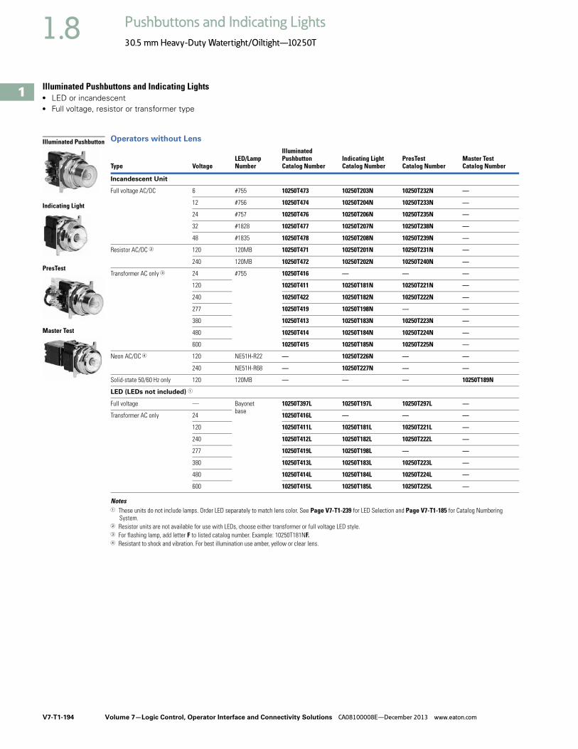
V7-T1-194 Volume 7—Logic Control, Operator Interface and Connectivity Solutions CA08100008E—December 2013 www.eaton.com
1
1
1
1
1
1
1
1
1
1
1
1
1
1
1
1
1
1
1
1
1
1
1
1
1
1
1
1
1
1
1.8 Pushbuttons and Indicating Lights
30.5 mm Heavy-Duty Watertight/Oiltight—10250T
Illuminated Pushbuttons and Indicating Lights● LED or incandescent● Full voltage, resistor or transformer type
Operators without Lens
Notes1 These units do not include lamps. Order LED separately to match lens color. See Page V7-T1-239 for LED Selection and Page V7-T1-185 for Catalog Numbering
System.2 Resistor units are not available for use with LEDs, choose either transformer or full voltage LED style.3 For flashing lamp, add letter F to listed catalog number. Example: 10250T181NF.4 Resistant to shock and vibration. For best illumination use amber, yellow or clear lens.
Type VoltageLED/LampNumber
IlluminatedPushbuttonCatalog Number
Indicating LightCatalog Number
PresTestCatalog Number
Master TestCatalog Number
Incandescent Unit
Full voltage AC/DC 6 #755 10250T473 10250T203N 10250T232N —
12 #756 10250T474 10250T204N 10250T233N —
24 #757 10250T476 10250T206N 10250T235N —
32 #1828 10250T477 10250T207N 10250T238N —
48 #1835 10250T478 10250T208N 10250T239N —
Resistor AC/DC 2 120 120MB 10250T471 10250T201N 10250T231N —
240 120MB 10250T472 10250T202N 10250T240N —
Transformer AC only 3 24 #755 10250T416 — — —
120 10250T411 10250T181N 10250T221N —
240 10250T422 10250T182N 10250T222N —
277 10250T419 10250T198N — —
380 10250T413 10250T183N 10250T223N —
480 10250T414 10250T184N 10250T224N —
600 10250T415 10250T185N 10250T225N —
Neon AC/DC 4 120 NE51H-R22 — 10250T226N — —
240 NE51H-R68 — 10250T227N — —
Solid-state 50/60 Hz only 120 120MB — — — 10250T189N
LED (LEDs not included) 1
Full voltage — Bayonetbase
10250T397L 10250T197L 10250T297L —
Transformer AC only 24 10250T416L — — —
120 10250T411L 10250T181L 10250T221L —
240 10250T412L 10250T182L 10250T222L —
277 10250T419L 10250T198L — —
380 10250T413L 10250T183L 10250T223L —
480 10250T414L 10250T184L 10250T224L —
600 10250T415L 10250T185L 10250T225L —
Illuminated Pushbutton
Indicating Light
PresTest
Master Test

Volume 7—Logic Control, Operator Interface and Connectivity Solutions CA08100008E—December 2013 www.eaton.com V7-T1-195
1
1
1
1
1
1
1
1
1
1
1
1
1
1
1
1
1
1
1
1
1
1
1
1
1
1
1
1
1
1
1.8Pushbuttons and Indicating Lights
30.5 mm Heavy-Duty Watertight/Oiltight—10250T
Indicating and Master Test Lenses
Illuminated Pushbutton Lenses
PresTest Lenses
ColorPlasticCatalog Number
GlassCatalog Number
Red 10250TC1N 10250TC7N
Green 10250TC2N 10250TC8N
Amber 10250TC19N 10250TC9N
Yellow 10250TC3N —
Blue 10250TC4N 10250TC10N
Clear 10250TC5N 10250TC11N
White 10250TC6N 10250TC12N
Color Catalog Number
Red 10250TC21
Green 10250TC22
Yellow 10250TC23
Amber 10250TC43
Blue 10250TC24
Clear 10250TC25
White 10250TC26
ColorPlasticCatalog Number
GlassCatalog Number
Red 10250TC21 10250TC13N
Green 10250TC22 10250TC14N
Amber 10250TC43 10250TC15N
Yellow 10250TC23 —
Blue 10250TC24 10250TC16N
Clear 10250TC25 10250TC17N
White 10250TC26 10250TC18N
Plastic
Glass
10250TC2_
Plastic
Glass

V7-T1-196 Volume 7—Logic Control, Operator Interface and Connectivity Solutions CA08100008E—December 2013 www.eaton.com
1
1
1
1
1
1
1
1
1
1
1
1
1
1
1
1
1
1
1
1
1
1
1
1
1
1
1
1
1
1
1.8 Pushbuttons and Indicating Lights
30.5 mm Heavy-Duty Watertight/Oiltight—10250T
Push-Pull Emergency Stops (Compliant with IEC 60947-5-5)UL (NEMA) Type 3, 3R, 4, 4X, 12, 13
● Two- and three-position● Non-illuminated● LONC contact block
Two-Position Push-Pull Units
Note1 X = closed circuit, O = open circuit.
Operator Position 1
Button Type/Color Lamp Type Voltage Catalog NumberPull Push
X O 40 mm red—illuminated Incandescent Transformer 120 Vac/Vdc 10250T563C47-71X
X O 40 mm red—illuminated EMERG. STOP Incandescent Transformer 120 Vac/Vdc 10250T563C53-71X
X O 40 mm red—illuminated EMERG. STOP LED Transformer 120 Vac/Vdc 10250T563LED06-71X
X O 40 mm red—illuminated Incandescent Full voltage 24 Vdc 10250T579C47-71X
X O 40 mm red—illuminated EMERG. STOP Incandescent Full voltage 24 Vdc 10250T579C53-71X
X O 40 mm red—illuminated Incandescent Resistor 120 Vac/Vdc 10250T580C47-71X
X O 40 mm red—illuminated EMERG. STOP Incandescent Resistor 120 Vac/Vdc 10250T580C53-71X
X O 40 mm red—illuminated Incandescent Transformer 24 Vac 10250T589C47-71X
X O 40 mm red—illuminated EMERG. STOP Incandescent Transformer 24 Vac 10250T589C53-71X
X O 40 mm red—illuminated EMERG. STOP LED Transformer 24 Vac 10250T589LED06-71X
X O 40 mm red—illuminated LED Transformer 24 Vac 10250T589LRD06-71X
X O 40 mm red—illuminated EMERG. STOP LED Full voltage 24 Vdc 10250T597LED24-71X
X O 40 mm red—illuminated EMERG. STOP LED Full voltage 120 Vac/Vdc 10250T597LED2A-71X
X O 40 mm red—illuminated LED Full voltage 24 Vdc 10250T597LRD24-71X
X O 40 mm red—illuminated LED Full voltage 120 Vac/Vdc 10250T597LRD2A-71X
X O 40 mm red — — — 10250T5B62-71X
X O 40 mm red — — — 10250T5B63-71X
X O 65 mm red — — — 10250T5J62-71X
X O 65 mm red — — — 10250T5J63-71X
10250T579C47-71X

Volume 7—Logic Control, Operator Interface and Connectivity Solutions CA08100008E—December 2013 www.eaton.com V7-T1-197
1
1
1
1
1
1
1
1
1
1
1
1
1
1
1
1
1
1
1
1
1
1
1
1
1
1
1
1
1
1
1.8Pushbuttons and Indicating Lights
30.5 mm Heavy-Duty Watertight/Oiltight—10250T
UL (NEMA) Type 3, 3R, 4, 4X, 12, 13
Two-Position Push-Pull Units
Button and Color Selection
Notes1 X = closed circuit, O = open circuit.2 To order different type or color buttons, substitute the underlined characters with appropriate suffix code from the table.
Example: 10250T5B64-1X.3 Anodized aluminum head is not suitable for use in ultraviolet light applications.
Operator Position 1
Button Type/Color 2ContactType Catalog Number 2
Pull Push Mounting Location
A B
Two-Position Maintained Push, Maintained Pull
OX
XO
40 mm/red 1NO 10250T5B62-1X
1NC
OX
XO
40 mm engravedEMERG. STOP/red
1NO 10250T5B63-1X
1NC
OX
XO
65 mm aluminum engravedEMERG. STOP/red
1NO 10250T5J63-1X
1NC
OX
XO
65 mm aluminum engravedEMERG. STOP/red
1NO 10250ED1080-2
Special security jumbo mushroom head
1NC
Color Suffix Code Catalog Number
Standard—40 mm
Red B62 10250TB62
Red (EMERG. STOP) B63 10250TB63
Green B61 10250TB61
Black B60 10250TB60
Blue B64 10250TB64
Jumbo Mushroom Head 3
(Anodized) Aluminum—65 mm
Red J62 10250TJ62
Red (EMERG. STOP) J63 10250TJ63
Green J61 10250TJ61
Black J60 10250TJ60
Yellow J64 10250TJ64
10250T5B63-1X
10250T5J63-1X
10250T5B62-1X
10250ED1080-2
Standard
Jumbo Mushroom Head

V7-T1-198 Volume 7—Logic Control, Operator Interface and Connectivity Solutions CA08100008E—December 2013 www.eaton.com
1
1
1
1
1
1
1
1
1
1
1
1
1
1
1
1
1
1
1
1
1
1
1
1
1
1
1
1
1
1
1.8 Pushbuttons and Indicating Lights
30.5 mm Heavy-Duty Watertight/Oiltight—10250T
UL (NEMA) Type 3, 3R, 4, 4X, 12, 13
Three-Position Push-Pull Units
Button and Color Selection
Notes1 X = closed circuit, O = open circuit.2 To order different type or color buttons, substitute the underlined characters with appropriate suffix code from the table.
Example: 10250T5B64-1X.3 Anodized aluminum head is not suitable for use in ultraviolet light applications.
Operator Position 1
Button Type/Color 2ContactType Catalog Number 2
Pull Intermediate Push Mounting Location
A B
Maintained Push, Momentary Pull
XX
OX
OO
40 mm/black 1NC 10250T9B60-3X
1NC40 mm/red 10250T9B62-3X
40 mm engravedEMERG. STOP/red
10250T9B63-3X
Momentary Push, Momentary Pull
XX
OX
OO
40 mm/black 1NC 10250T4B60-3X
1NC40 mm/red 10250T4B62-3X
OX
OO
XO
40 mm/black 1NO 10250T10B60-1X
1NC40 mm/red 10250T10B62-1X
Color Suffix Code Catalog Number
Standard—40 mm
Red B62 10250TB62
Red (EMERG. STOP) B63 10250TB63
Green B61 10250TB61
Black B60 10250TB60
Blue B64 10250TB64
Jumbo Mushroom Head 3
(Anodized) Aluminum—65 mm
Red J62 10250TJ62
Red (EMERG. STOP) J63 10250TJ63
Green J61 10250TJ61
Black J60 10250TJ60
Yellow J64 10250TJ64
10250T_
Standard
Jumbo Mushroom Head
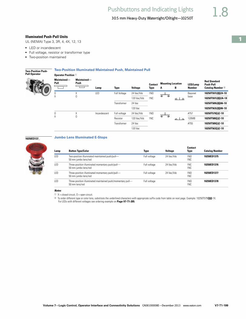
Volume 7—Logic Control, Operator Interface and Connectivity Solutions CA08100008E—December 2013 www.eaton.com V7-T1-199
1
1
1
1
1
1
1
1
1
1
1
1
1
1
1
1
1
1
1
1
1
1
1
1
1
1
1
1
1
1
1.8Pushbuttons and Indicating Lights
30.5 mm Heavy-Duty Watertight/Oiltight—10250T
Illuminated Push-Pull UnitsUL (NEMA) Type 3, 3R, 4, 4X, 12, 13
● LED or incandescent● Full voltage, resistor or transformer type● Two-position maintained
Two-Position Illuminated Maintained Push, Maintained Pull
Jumbo Lens Illuminated E-Stops
Notes1 X = closed circuit, O = open circuit.2 To order different type or color lens, substitute the underlined characters with appropriate suffix code from table on next page. Example: 10250T579C63-1X.
For LEDs with different voltages see ordering example on Page V7-T1-205.
Operator Position 1
Lamp Type VoltageContactType
LED/LampNumber
Red Standard Push-PullCatalog Number 2
Maintained—Pull
Maintained—Push Mounting Location
A B
OX
XO
LED Full Voltage 24 Vac/Vdc 1NO Bayonetbase
10250T597LRD24-1X
1NC120 Vac/Vdc 10250T597LRD2A-1X
Transformer 24 Vac 10250T589LRD06-1X
120 Vac 10250T563LRD06-1X
OX
XO
Incandescent Full voltage 24 Vac/Vdc 1NO #757 10250T579C47-1X
1NCResistor 120 Vac/Vdc 120MB 10250T580C47-1X
Transformer 24 Vac #755 10250T589C47-1X
120 Vac 10250T563C47-1X
Lamp Button Type/Color Type VoltageContactType Catalog Number
LED Two-position illuminated maintained push/pull—50 mm jumbo lens/red
Full voltage 24 Vac/Vdc 1NO1NC
10250ED1375
LED Three-position illuminated momentary push/pull—50 mm jumbo lens/red
Full voltage 24 Vac/Vdc 1NC1NC
10250ED1376
LED Three-position illuminated momentary push/pull—50 mm jumbo lens/red
Full voltage 24 Vac/Vdc 1NO1NC
10250ED1377
LED Three-position illuminated maintained push/momentary pull—50 mm lens/red
Full voltage 1NO1NC
10250ED1378
Two-Position Push-Pull Operator
10250ED137_

V7-T1-200 Volume 7—Logic Control, Operator Interface and Connectivity Solutions CA08100008E—December 2013 www.eaton.com
1
1
1
1
1
1
1
1
1
1
1
1
1
1
1
1
1
1
1
1
1
1
1
1
1
1
1
1
1
1
1.8 Pushbuttons and Indicating Lights
30.5 mm Heavy-Duty Watertight/Oiltight—10250T
UL (NEMA) Type 3, 3R, 4, 4X, 12, 13
Lens and Color Selection
Note1 Clear anodized aluminum and colored lens.
ColorIncandescentSuffix Code
LEDSuffix Code Catalog Number
Standard—40 mm
Red C47 RD 10250TC47
Red (EMERG. STOP) C53 ED 10250TC53
Green C48 GD 10250TC48
Blue C49 LD 10250TC49
Amber C50 AD 10250TC50
White C51 WD 10250TC51
Clear C52 CD 10250TC52
Side-Lighted Aluminum—40 mm 1
Red C57 RS 10250TC57
Red (EMERG. STOP) C63 ES 10250TC63
Green C58 GS 10250TC58
Blue C59 LS 10250TC59
Amber C64 AS 10250TC64
Yellow C60 YS 10250TC60
White C61 WS 10250TC61
Clear C62 CS 10250TC62
Aluminum Transparent Center—40 mm 1
Red C65 RH 10250TC65
Green C66 GH 10250TC66
Amber C67 AH 10250TC67
Jumbo Lens—50 mm
Red — — 10250TC77
Standard
Side-Lighted Aluminum
Aluminum Transparent Center
Jumbo Lens

Volume 7—Logic Control, Operator Interface and Connectivity Solutions CA08100008E—December 2013 www.eaton.com V7-T1-201
1
1
1
1
1
1
1
1
1
1
1
1
1
1
1
1
1
1
1
1
1
1
1
1
1
1
1
1
1
1
1.8Pushbuttons and Indicating Lights
30.5 mm Heavy-Duty Watertight/Oiltight—10250T
UL (NEMA) Type 3, 3R, 4, 4X, 12, 13
Three-Position Illuminated Momentary Push, Momentary Pull
Three-Position Illuminated Maintained Push, Momentary Pull
Notes1 X = closed circuit, O = open circuit.2 To order different type or color lens, substitute the underlined characters with appropriate suffix code from table on Page V7-T1-200.
Example: 10250T1079C53-1X. For LEDs with different voltages see ordering example on Page V7-T1-205.3 To order different type or color lens, substitute the underlined characters with appropriate suffix code from table on Page V7-T1-200.
Example: 10250T979C53X. For LEDs with different voltages see ordering example on Page V7-T1-205.
Operator Position 1
Lamp Type VoltageContact Type
LED/LampNumber
Red Standard Push-Pull Catalog Number 3
Momentary—Pull
Maintained—Intermediate
Momentary—Push Mounting Location
A B
OX
OO
XO
LED Full voltage 24 Vac/Vdc 1NO Bayonetbase
10250T1097LRD24-1X
1NC120 Vac 10250T1097LRD2A-1X
Transformer 24 Vac 10250T1089LRD06-1X
120 Vac 10250T1063LRD06-1X
XX
OX
OO
Full voltage 24 Vac/Vdc 1NC Bayonetbase
10250T497LRD24-3X
1NC120 Vac 10250T497LRD2A-3X
Transformer 24 Vac 10250T489LRD06-3X
120 Vac 10250T463LRD06-3X
OX
OO
XO
Incan-descent
Full voltage 24 Vac/Vdc 1NO #757 10250T1079C47-1X
1NCResistor 120 Vac 120MB 10250T1080C47-1X
Transformer 24 Vac #755 10250T1089C47-1X
120 Vac 10250T1063C47-1X
XX
OX
OO
Full voltage 24 Vac/Vdc 1NC #757 10250T479C47-3X
1NCResistor 120 Vac 120MB 10250T480C47-3X
Transformer 24 Vac #755 10250T489C47-3X
120 Vac 10250T463C47-3X
Operator Position 1
Lamp Type VoltageContact Type
LED/LampNumber
Red Standard Push-Pull Catalog Number 2
Momentary—Pull
Maintained—Intermediate
Momentary—Push Mounting Location
A B
XX
OX
OO
LED Full voltage 24 Vac/Vdc 1NC Bayonetbase
10250T997LRD24-3X
1NC120 Vac 10250T997LRD2A-3X
Transformer 24 Vac 10250T989LRD06-3X
120 Vac 10250T963LRD06-3X
XX
OX
OO
Incan-descent
Full voltage 24 Vac/Vdc 1NC #757 10250T979C47-3X
1NCResistor 120 Vac 120MB 10250T980C47-3X
Transformer 24 Vac #755 10250T989C47-3X
120 Vac 10250T963C47-3X
Three-Position Push-Pull Operator
Three-Position Push-Pull Operator

V7-T1-202 Volume 7—Logic Control, Operator Interface and Connectivity Solutions CA08100008E—December 2013 www.eaton.com
1
1
1
1
1
1
1
1
1
1
1
1
1
1
1
1
1
1
1
1
1
1
1
1
1
1
1
1
1
1
1.8 Pushbuttons and Indicating Lights
30.5 mm Heavy-Duty Watertight/Oiltight—10250T
PotentiometersUL (NEMA) Type 3, 3R, 4, 12, 13
Potentiometer with Knob and Standard Dial Plate—Linear Type ±10%
Notes1 Shown with standard aluminum dial plate.2 Large dial plate with space for legend is available at no charge. To order, add suffix 36 to catalog number.
Example: 10250T33136. To order separately, see footnote 3 below.3 Large dial plate has space at top for 15 letters. 3/32 in high. For custom stamped legend plates,
order legend plate as separate item 10250TR30 and specify stamping.4 For use with commercially purchased potentiometers having shaft dimensions per dimension drawing
on Page V7-T1-249.
PotentiometerOhms Catalog Number
2 Watt (60V Max.) Single Potentiometer with Standard Aluminum Dial Plate 23
1000 10250T331
2500 10250T332
5000 10250T338
10000 10250T333
25000 10250T334
50000 10250T335
Operator only 4 10250T330
Alternative—black plastic large legend with standard markings E34LP99
Vertical or Horizontal 1One-Hole Mounting

Volume 7—Logic Control, Operator Interface and Connectivity Solutions CA08100008E—December 2013 www.eaton.com V7-T1-203
1
1
1
1
1
1
1
1
1
1
1
1
1
1
1
1
1
1
1
1
1
1
1
1
1
1
1
1
1
1
1.8Pushbuttons and Indicating Lights
30.5 mm Heavy-Duty Watertight/Oiltight—10250T
Push-Pull OperatorsAn illuminated push-pull pushbutton unit, arranged for one-hole mounting, can replace two pushbuttons and a pilot light or the non-illuminated form can replace two pushbuttons. These units are available in three basic types:
● Maintained—(Two-position). Maintains in the pulled or pushed position until manually actuated to the opposite mode.
● Momentary—(Three-position). Spring returns to an intermediate position when pulled or pushed and released.
● Momentary Pull, Maintained Push—(Three-position). Spring returns to intermediate position when pulled. Maintains in pushed position until manually returned to intermediate (ready to reset) position. Maintained stop holds circuit open and will prevent other series connected operators from starting the system.
The operators, buttons, contact blocks, etc., are offered as building block components that can be intermixed to satisfy many requirements. This minimizes the need for a varied and costly inventory.
Typical Applications
NotesA and B circuits shown in the application illustrations are defined in the “Application Guide” on the following page.1 Shown without button on lens.
Control Line—Diagram Operator Circuits Operator Mode
Three-wire three-positionmomentary
Momentarypush and pull10250T4
2NC contact block10250T3
START (mom.) Normal pos. (maint.)
STOP (mom.)
Momentarypush and pull10250T10
1NO-1NCcontact block10250T1
Two-wire two-positionmaintained
Maintainedpush and pull10250T5
1NCcontact block10250T51
START (maint.) No intermediateposition
STOP (maint.)
Three-wiremomentary pullmaintained push
Maintainedpush andmomentarypull10250T9
2NCcontact block10250T3
START (mom.) Normal pos. (maint.)
STOP (maint.)
Two-Position Maintained Push-Pull 1
M
L2L1
OL
MB Circuit
A CircuitPush-PullOperator
M
L2L1
OL
B CircuitorA
Push-PullOperator
M
L2L1
OL
MB Circuit
A CircuitPush-PullOperator

V7-T1-204 Volume 7—Logic Control, Operator Interface and Connectivity Solutions CA08100008E—December 2013 www.eaton.com
1
1
1
1
1
1
1
1
1
1
1
1
1
1
1
1
1
1
1
1
1
1
1
1
1
1
1
1
1
1
1.8 Pushbuttons and Indicating Lights
30.5 mm Heavy-Duty Watertight/Oiltight—10250T
Application GuideTo assist in the selection of contact blocks, the sketch to the right shows pictorially by symbols A and B locations of contact circuits after assembly of contact blocks
and adapter to the operator. The table below shows the effect of the push and pull operations on either NO or NC contacts. (X = contact closed, O = contact open).
Contact Circuit Locations
Push-Pull Operator Components
Note1 Maximum of two blocks, four circuits. Special function contact blocks shown on Page V7-T1-235 CANNOT be used with three-position push-pull operators 10250T4,
10250T9 or 10250T10.
Locating Nib
A
B
Type of Operator
Operator Position and Circuit Arrangement
Contact Block 1 Catalog Number
Out—Pull Intermediate In—Push
Contact Block Mounting LocationA B A B A B
Two-Position Operator without Lens
Maintained push-pull OX or O
XNo intermediateposition
XO or X
O1NO1NC
10250T5
OX
OX
XO
XO
2NO2NC
Maintained push-pull withanti-theft jumbo mushroom
OX or O
XNo intermediateposition
XO or X
O1NO1NC
10250ED1080
OX
OX
XO
XO
2NO2NC
Three-Position Operator without Lens
Momentary push-pull OX or O
XOO or O
XXO or O
O1NO1NC
10250T4 1
OX
OX
OO
OX
XO
OO
2NO2NC
Maintained push-momentary pull OX or O
XOO or O
XXO or O
O1NO1NC
10250T9 1
OX
OX
OO
OX
XO
OO
2NO2NC
Momentary push-pull OX or O
XOO or O
OXO or X
O1NO1NC
10250T10 1
OX
OX
OO
OO
XO
XO
2NO2ND
10250T579C47-71X

Volume 7—Logic Control, Operator Interface and Connectivity Solutions CA08100008E—December 2013 www.eaton.com V7-T1-205
1
1
1
1
1
1
1
1
1
1
1
1
1
1
1
1
1
1
1
1
1
1
1
1
1
1
1
1
1
1
1.8Pushbuttons and Indicating Lights
30.5 mm Heavy-Duty Watertight/Oiltight—10250T
Push-Pull Light Units, Lenses and ButtonsOrdering Example with One Composite Number
Non-illuminated: 10250T5 + 10250TB62 + 10250T1 = 10250T5B62-1X
Incandescent: 10250T5 + 10250T79 + 10250TC47 + 10250T1 = 10250T579C47-1X
LED: 10250T5 + 10250T97L + 10250TC47 + Voltage code + 10250T1 = 10250T597LRD24-1X
06—6 Vac/Vdc12—12 Vac/Vdc24—24 Vac/Vdc48—48 Vac/Vdc
60—60 Vac/Vdc2A—120 Vac2D—120 Vdc
Light Units for Illuminated Push-Pull Devices
Note1 These units do not include lamps. Order LED separately to match lens color, see Page V7-T1-239.
Light Unit Type Type Voltage
LED/LampNumber Catalog Number
LED(LEDs not included)
1Full voltage — Bayonet
base10250T97L
Transformer AC only50/60 Hz
24120208240277380480600
10250T89L10250T63L10250T64L10250T65L10250T82L10250T66L10250T67L10250T68L
Incandescent Full voltageAC or DC
61224/2832
10250T6910250T7010250T7910250T83
ResistorAC or DC
120240
120MB 10250T8010250T81
TransformerAC only50/60 Hz
24120208240277380480600
#755 10250T8910250T6310250T6410250T6510250T8210250T6610250T6710250T68

V7-T1-206 Volume 7—Logic Control, Operator Interface and Connectivity Solutions CA08100008E—December 2013 www.eaton.com
1
1
1
1
1
1
1
1
1
1
1
1
1
1
1
1
1
1
1
1
1
1
1
1
1
1
1
1
1
1
1.8 Pushbuttons and Indicating Lights
30.5 mm Heavy-Duty Watertight/Oiltight—10250T
Alternate Lenses for Illuminated Push-Pull Devices
Buttons for Non-Illuminated Push-Pull Devices
Notes1 Suffix codes should only be used for assembling composite catalog numbers. To order lens above, order by catalog number.2 Anodized aluminum head is not suitable for use in ultraviolet light applications.
Lens ColorIncandescentSuffix Code
LED Suffix Code 1 Catalog Number
Standard
Red C47 RD 10250TC47
Red (EMERG. STOP) C53 ED 10250TC53
Green C48 GD 10250TC48
Blue C49 LD 10250TC49
Amber C50 AD 10250TC50
White C51 WD 10250TC51
Clear C52 CD 10250TC52
Side-Lighted Anodized Aluminum Ring
Red C57 RS 10250TC57
Red (EMERG. STOP) C63 ES 10250TC63
Green C58 GS 10250TC58
Blue C59 LS 10250TC59
Amber C64 AS 10250TC64
Yellow C60 YS 10250TC60
White C61 WS 10250TC61
Clear C62 CS 10250TC62
Heavy-Duty Aluminum with Transparent Center
Red C65 RH 10250TC65
Green C66 GH 10250TC66
Amber C67 AH 10250TC67
White C68 — 10250TC68
Jumbo Lens—50 mm
Red — — 10250TC77
Color Suffix Code Catalog Number Legend PlatesFor a complete listing of available legend plates see Pages V7-T1-230 to V7-T1-232.
Standard
Red B62 10250TB62
Red (EMERG. STOP) B63 10250TB63
Green B61 10250TB61
Black B60 10250TB60
Blue B64 10250TB64
Jumbo Mushroom Head 2
(Anodized) Aluminum
Red J62 10250TJ62
Red (EMERG. STOP) J63 10250TJ63
Green J61 10250TJ61
Black J60 10250TJ60
Yellow J64 10250TJ64
Standard
Side-Lighted Anodized Aluminum Ring
Heavy-Duty Aluminum
Jumbo Lens
Standard
Jumbo Mushroom Head
Standard
Jumbo
PS
RT

Volume 7—Logic Control, Operator Interface and Connectivity Solutions CA08100008E—December 2013 www.eaton.com V7-T1-207
1
1
1
1
1
1
1
1
1
1
1
1
1
1
1
1
1
1
1
1
1
1
1
1
1
1
1
1
1
1
1.8Pushbuttons and Indicating Lights
30.5 mm Heavy-Duty Watertight/Oiltight—10250T
Selector Switch UnitsUL (NEMA) Type 3, 3R, 4, 4X, 12, 13
● Two-, three- and four-position maintained● Non-illuminated and illuminated
Two-Position Selector Switch
Three-Position Selector Switch
Four-Position Selector Switch
Color Selection
Notes1 X = closed circuit, O = open circuit.2 M = Maintained.3 To order different type or color selector switch, substitute the underlined character with appropriate suffix code from the Color Selection table. Example: 10250T20KG.
Operator Position 1
OperatorAction 2
Contact Type
Non-Illuminated Illuminated—120V TransformerMounting Location Black Knob
Catalog Number 3Black LeverCatalog Number 3
Red KnobCatalog Number 3
Red LeverCatalog Number 3A B
X O 1NC 10250T20KB 10250T20LB 10250ED1117-KR 10250ED1117-LR
O X 1NO
Operator Position 1
OperatorAction 2
Contact Type
Non-Illuminated Illuminated—120V TransformerMounting Location Black Knob
Catalog Number 3Black LeverCatalog Number 3
Red KnobCatalog Number 3
Red LeverCatalog Number 3A B
X O O 1NO 10250T21KB 10250T21LB 10250ED1117-2KR 10250ED1117-2LR
O O X 1NO
X O O 1NO 10250T22KB 10250T22LB 10250ED1117-3KR 10250ED1117-3LR
O X O 2NC (Series)
O O X 1NO
Operator Position 1
OperatorAction 2
Contact Type
Non-Illuminated Illuminated—120V TransformerMounting Location Black Knob
Catalog Number 3Black LeverCatalog Number 3
Red KnobCatalog Number 3
Red LeverCatalog Number 3A B
X O O O 1NC 10250T46KB 10250T46LB 10250ED1117-4KR 10250ED1117-4LR
O X O O 1NO
O O X O 1NO
O O O X 1NC
Illuminated Non-Illuminated
ColorCodeLetter Color
CodeLetter Color
CodeLetter Color
CodeLetter Color
CodeLetter Color
CodeLetter
RedGreen
RG
WhiteBlue
WB
AmberClear
AC
BlackRed
BR
GreenWhite
GW
BlueOrange
LO
Two-Position Maintained Switch
M M
Three-Position Maintained Switch
Three-Position Maintained Switch
M M
M
Three-Position Maintained Switch
M M
M M
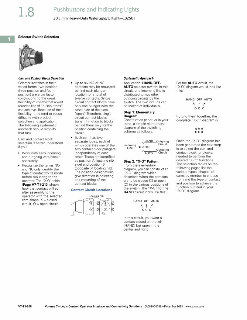
V7-T1-208 Volume 7—Logic Control, Operator Interface and Connectivity Solutions CA08100008E—December 2013 www.eaton.com
1
1
1
1
1
1
1
1
1
1
1
1
1
1
1
1
1
1
1
1
1
1
1
1
1
1
1
1
1
1
1.8 Pushbuttons and Indicating Lights
30.5 mm Heavy-Duty Watertight/Oiltight—10250T
Selector Switch Selection
Cam and Contact Block SelectionSelector switches in their varied forms (two-position, three-position and four-position) are a big factor contributing to the great flexibility of control that a well rounded line of “pushbuttons” can achieve. Because of their flexibility, they tend to cause difficulty with product selection and application. The following systematic approach should simplify that task.
Cam and contact block selection is better understood if you:
● Work with each incoming and outgoing wire/circuit separately.
● Recognize the terms NO and NC only identify the type of contact by its mode before mounting to the operator. The “X-O” table (Page V7-T1-210) shows how that contact will act after assembly to the operator with the selected cam shape. X = closed circuit, O = open circuit.
● Up to six NO or NC contacts may be mounted behind each plunger location for a total of twelve contacts. Single circuit contact blocks have only one plunger with the other side of the block “open.” Therefore, single circuit contact blocks transmit motion to blocks behind them only for the position containing the circuit.
● Each cam has two separate lobes, each of which operates one of the two contact block plungers independently of each other. Those are identified as position A (locating nib side) and position B (opposite of locating nib). The position designations give direction in selecting and mounting of the contact blocks.
Contact Circuit Locations
Locating Nib
A
B
Systematic ApproachApplication: HAND-OFF-AUTO selector switch. In this circuit, one incoming line is distributed to two other outgoing circuits by the switch. The two circuits can be looked at individually.
Step 1: Elementary Diagram. Construct on paper, or in your mind, a simple elementary diagram of the switching scheme as follows:
Step 2: “X-O” Pattern. From the elementary diagram, you can construct an “X-O” diagram which describes when the contacts are to be closed (X) or open (O) in the various positions of the switch. The “X-O” for the HAND circuit looks like this:
In this circuit, you want a contact closed on the left (HAND) but open in the center and right.
For the AUTO circuit, the “X-O” diagram would look like this:
Putting them together, the complete “X-O” diagram is:
Once the “X-O” diagram has been generated the next step is to select the cam and contact block, or blocks, needed to perform the desired “X-O” functions. The selection tables on the following pages list the various types (shapes) of cams by number to choose from and the type of contact and position to achieve the function outlined in your “X-O” diagram.
OFF
HAND OutgoingCircuit
AUTO
OutgoingCircuit
IncomingLine
HAND OFF AUTO
X O O
HAND OFF AUTO
O O X
X O OO O X

Volume 7—Logic Control, Operator Interface and Connectivity Solutions CA08100008E—December 2013 www.eaton.com V7-T1-209
1
1
1
1
1
1
1
1
1
1
1
1
1
1
1
1
1
1
1
1
1
1
1
1
1
1
1
1
1
1
1.8Pushbuttons and Indicating Lights
30.5 mm Heavy-Duty Watertight/Oiltight—10250T
Step 3: Cam Selection. The cam you select determines the operation of all contact blocks mounted to the operator. It is selected on the basis that it provides the simplest circuitry for the desired “X-O” diagram. The selection tables show all the “X-O” combinations. For the purpose of this example, the applicable portion of those tables is shown on this page.
Now to make the cam selection, make a simple worksheet such as:
It becomes immediately obvious that cam 3 is the better choice for two reasons, (1) the series combination can be avoided making it simpler to wire, (2) only two contacts are required, which is less expensive than the three contacts required by cam 2.
Step 4: Contact Block Selection. Having selected the cam, contact block selection is simply a matter of gathering the A position and B position circuits into pairs which make up the most convenient contact block arrangement. If there is an imbalance in the number of circuits under A or B, then single circuit blocks must be selected for these leftover circuits.
Back to the worksheet, having selected cam 3 do this:
Step 5: Selector Switch Operator. Lastly, you have to choose from the many types of operators—knob and lever in various colors or keyed. Also what combinations of maintained and spring return functions are required. Selection of these operators can be found on Page V7-T1-212. For the example in step 4 you may want a three-position maintained black knob, cam 3—Catalog Number 10250T1323.
The Complete Switch: 10250T1323 with one 10250T2 or, for one composite catalog number, 10250T21KB found on Page V7-T1-207.
DiagramsCircuits shown illustrate connections to obtain a selector switch circuit combination and are shown with their appropriate line diagrams. Field wiring of jumper connections required as shown.
X = Closed circuitO = Open circuit
Wiring of Jumper Connections
Four-position selector switches are limited to four contact blocks.
Contact BlocksFor selection and number of available contact blocks per operator, see Pages V7-T1-235 to V7-T1-238.
Cam 2 Cam 3
X O O
O O X
(A)NO-(B)NC
(B)NO
(A)NO
(B)NO
X O X
O O X
ANO
BNO10250T2
Parallel Connection
Series Connection
Example Selection Table
Two-Position Selector Switch Contact Block Selection
Note1 Wired in series.
No. “X-O” PatternCam Code #2 Cam Code #3Top A Bottom B Top A Bottom B
1 X O O
NO NC NO
—
4 O O X —
NO
—
NO
No.
Desired Circuit andOperator Position
Contact Blocks Required to Accomplish Circuit FunctionTop Plunger A Bottom Plunger B
1 X ONC or NC
2 O X
NOor
NO
a

V7-T1-210 Volume 7—Logic Control, Operator Interface and Connectivity Solutions CA08100008E—December 2013 www.eaton.com
1
1
1
1
1
1
1
1
1
1
1
1
1
1
1
1
1
1
1
1
1
1
1
1
1
1
1
1
1
1
1.8 Pushbuttons and Indicating Lights
30.5 mm Heavy-Duty Watertight/Oiltight—10250T
Three-Position Switch—Cam and Contact Block Selection
Four-Position Switch—Contact Block Selection
No.
Desired Circuit andOperator Position
Contact Blocks Required to Accomplish Circuit Function(Jumpers must be installed where indicated)Operator with Cam Code #2 Operator with Cam Code #3Mounting Location Mounting LocationTop PlungerA
Bottom PlungerB
Top PlungerA
Bottom PlungerB
1 X O O
NO NC NO
2 X X ONC NC
3 X O X
NONO NO
4 O O X
NO NO
5 O X X
NC NONC
6 O X ONC NC NC
No.
Contact Blocks Required to Accomplish Circuit Function
No.
Contact Blocks Required to Accomplish Circuit Function
Desired Circuit andOperator Position
Mounting Location Desired Circuit andOperator Position
Mounting LocationTop PlungerA
Bottom PlungerB
Top PlungerA
Bottom PlungerB
1 X O O ONC
10 X O X O
NCNO
2 O X O O
NO
3 O O X O
NO
11 X X X O
NCNO NO
4 O O O XNC
5 X O O X
NC NC
12 O X X X
NO NCNO
6 O X X O
NO NO
7 O O X X
NO NC
13 X O X X
NONC NC
8 X X O O
NC NO
9 O X O X
NONC
14 X X O X
NC NONC

Volume 7—Logic Control, Operator Interface and Connectivity Solutions CA08100008E—December 2013 www.eaton.com V7-T1-211
1
1
1
1
1
1
1
1
1
1
1
1
1
1
1
1
1
1
1
1
1
1
1
1
1
1
1
1
1
1
1.8Pushbuttons and Indicating Lights
30.5 mm Heavy-Duty Watertight/Oiltight—10250T
Selector Switch Operators
Key OperatorsUL (NEMA) Type 3, 3R, 4, 4X, 12, 13
Key Operators with Cam
Notes1 Horizontal mount, key removal #1 keyed selector switch, cam 1 shown.2 M = Maintained. S = Spring return in direction of arrow (R).3 For selection of the proper cam and contact block to obtain the proper circuit sequence, see selection instructions and tables on
Pages V7-T1-208, V7-T1-209 and V7-T1-210.4 Choose key removal position required for application from table on Page V7-T1-212. Add key removal code no. to listed catalog number.
Example: 10250T15112.
Positions Operator Action 2 Cam Code 3Optional Key Removal Positions 4
Vertical MountingCatalog Number
Horizontal MountingCatalog Number
Two-position—60° throw 1 1, 2, 3 10250T1511_ 10250T1611_
1 2 10250T1571_ 10250T1581_
Three-position—60° throw 2 1–7 10250T1522_ 10250T1622_
3 10250T1523_ 10250T1623_
2 1, 4, 5 10250T1532_ 10250T1632_
3 10250T1533_ 10250T1633_
2 4 10250T1542_ 10250T1642_
3 10250T1543_ 10250T1643_
2 2, 4, 6 10250T1652_ 10250T1662_
3 10250T1653_ 10250T1663_
Four-position—40° throw 7 7 10250T1677_ 10250T1687_
Two-Position Maintained 1
M M
M S
M M
M
MS
M
S S
M
M S
M
M M
M M

V7-T1-212 Volume 7—Logic Control, Operator Interface and Connectivity Solutions CA08100008E—December 2013 www.eaton.com
1
1
1
1
1
1
1
1
1
1
1
1
1
1
1
1
1
1
1
1
1
1
1
1
1
1
1
1
1
1
1.8 Pushbuttons and Indicating Lights
30.5 mm Heavy-Duty Watertight/Oiltight—10250T
Key Removal Positions
Note: Key removal in “spring return from” positions not recommended.
Replacement Keys or Dissimilar Locks for Key OperatorsOperators listed on Page V7-T1-212 have identical locks and keys (Key Code H661) Catalog Number 10250ED824. For dissimilar lock and key combinations, see listing on this page.
Replacement Key
Selector Switch Operators with Dissimilar Locks and Keys (UL [NEMA] 4, 4X and 13)The locks in all key operators listed on Pages V7-T1-191, V7-T1-212 and V7-T1-349 are identical and use key code number H661. Two keys are supplied with every lock. For additional code number H661 keys, order Catalog Number 10250ED824. For others, order 10250ED1130 and designate lock number. When dissimilar locks for each operator or each group of operators are required, select from the lock and key combination listed below. When Ordering Operator Only or a complete control unit with a substitute lock, order from table below and add “except Lock and Key Code No. …”
“H” Series Locks without Master Key—with Key Slot Cover
“M” Series Locks with Master Key—with Key Slot Cover
Master Keys for Above Locks
Selector Switch Operators with CapsUL (NEMA) Type 3, 3R, 4, 4X, 12, 13
Selector Switch Operators with Caps
Notes1 Black knob selector switch, cam 1 shown.2 M = Maintained. S = Spring return in direction of arrow (R).3 Field convertible to horizontal mounting or order operator only and separate operator cap.4 For selection of the proper cam and contact block to obtain the proper circuit sequence, see selection instructions and
tables on Pages V7-T1-208, V7-T1-209 and V7-T1-210.5 Black lever selector switch, cam 3 shown.
CodeSuffix
Key RemovalPosition
1 Right only
2 Left only
3 Right and left
4 Center only
5 Right and center
6 Left and center
7 All positions
L
C
R
Description Catalog Number
Replacement keys (code H661)
10250ED824Lock and Key Code Numbers
H501 H635 H663
H620 H639 H675
H621 H643 H683
H634 H654 H688
Lock and Key Code Numbers
MD1 MD14 ME8 MJ6
MD2 MD15 ME11 MJ10
MD3 MD16 ME16 MJ11
MD4 MD19 ME17 MJ13
MD5 MD20 ME18 MJ15
MD7 ME2 ME19 MJ16
MD9 ME3 MJ1 MD17
MD10 ME5 MJ3
MD11 ME6 MJ4
MD13 ME7 MJ5
Application Catalog Number
For code:
MD1–MD20 10250ED825-3
ME2–ME18 10250ED825-4
MJ1–MJ16 10250ED825-5
Positions Operator Action 2
Black Knob Selector Switch—Vertical Mounting 3
Black Lever Selector Switch—Vertical Mounting 3
Cam Code 4 Catalog Number Cam Code 4 Catalog Number
Two-position—60° throw 1 10250T1311 1 10250T3011
1 10250T1371 1 10250T3071
Three-position—60° throw 2 10250T1322 2 10250T30223 10250T1323 3 10250T3023
2 10250T1332 2 10250T30323 10250T1333 3 10250T30332 10250T1342 2 10250T3043 10250T1343 3 10250T30432 10250T1352 2 10250T30523 10250T1353 3 10250T3053
Four-position—40° throw 7 10250T1367 7 10250T3067
Two-Position Maintained 1
Three-Position Maintained 5
M M
M S
M M
M
MS
M
S S
M
M S
M
M M
M M

Volume 7—Logic Control, Operator Interface and Connectivity Solutions CA08100008E—December 2013 www.eaton.com V7-T1-213
1
1
1
1
1
1
1
1
1
1
1
1
1
1
1
1
1
1
1
1
1
1
1
1
1
1
1
1
1
1
1.8Pushbuttons and Indicating Lights
30.5 mm Heavy-Duty Watertight/Oiltight—10250T
Selector Switch Operators without CapsOperators can be ordered with caps assembled to them by adding the code number from the table on this page to the end of catalog number below. Example: 10250T4011KB
Selector Switch Operators without Caps
Operating Caps
Notes1 M = Maintained. S = Spring return in direction of arrow (R).2 For selection of the proper cam and contact block to obtain the proper circuit sequence, see selection instructions and
tables on Pages V7-T1-208, V7-T1-209 and V7-T1-210.3 Designed for added ingress protection. For use in maintained operators only.
Positions Operator Action 1 Cam Code 2 Catalog Number
Two-position—60° throw 1 10250T4011
1 10250T4081
Three-position—60° throw 2 10250T4022
3 10250T4023
2 10250T4032
3 10250T4033
2 10250T4042
3 10250T4043
2 10250T4052
3 10250T4053
Four-position—40° throw 7 10250T4067
Color
KnobCatalog andCode Number
LeverCatalog andCode Number Color
Lever 3Catalog andCode Number
Coin Slot Catalog andCode Number
Black 10250TKB 10250TLB Black 10250TSB 10250TCB
Red 10250TKR 10250TLR Red 10250TSR 10250TCR
Green 10250TKG 10250TLG Green 10250TSG 10250TCG
Yellow 10250TKY 10250TLY Yellow 10250TSY 10250TCY
White 10250TKW 10250TLW White 10250TSW 10250TCW
Gray 10250TKA 10250TLA Gray 10250TSA 10250TCA
Blue 10250TKL 10250TLL Blue 10250TSL 10250TCL
Orange 10250TKD 10250TLO Orange 10250TSO 10250TCO
Two-Position Selector Switch Maintained
M M
M S
M M
M
MS
M
S S
M
M S
M
M M
M M
Knob
Lever
Lever for Use with Maintained Operators
Coin Slot

V7-T1-214 Volume 7—Logic Control, Operator Interface and Connectivity Solutions CA08100008E—December 2013 www.eaton.com
1
1
1
1
1
1
1
1
1
1
1
1
1
1
1
1
1
1
1
1
1
1
1
1
1
1
1
1
1
1
1.8 Pushbuttons and Indicating Lights
30.5 mm Heavy-Duty Watertight/Oiltight—10250T
Illuminated Selector Switch Operators
Illuminated Selector Switches without Caps
Operator without Knob or Lever
Notes1 M = Maintained. S = Spring return in direction of arrow (R).2 For selection of the proper cam and contact block, to obtain the proper circuit sequence, see selection tables on Pages V7-T1-208, V7-T1-209 and V7-T1-210.3 Operator includes lens gasket and lens attachment screws.4 Full voltage light units can be used at other than listed voltages by changing lamp. Replacement lamps are listed on Page V7-T1-239.5 Resistor type. May generate excess heat if used in high density.
Positions Operator Action 1
Transformer Type—50/60 Hz
6 Volt #755 Lamp
Full Voltage Type—AC or DC 4
Lamps: 6V—#755, 12V—#756, 24V—#757,48V—#1835, 120/240V—120MB
CamCode 2 Voltage
Code Number andCatalog Number 3
CamCode 2 Voltage
Code Number andCatalog Number 3
Two-position—60° throw 1 24 10250T5961 1 6 10250T6201
120 10250T5971 12 10250T6211
208 10250T6511 24 10250T6221
240 10250T5981 48 10250T6231
380 10250T5991 120 10250T6361
480 10250T6001 240 5 10250T6371
600 10250T6011
Three-position—60° throw + 2 or 3 24 10250T602_ + 2 or 3 6 10250T624_
120 10250T603_ 12 10250T625_
208 10250T652_ 24 10250T626_
240 10250T604_ 48 10250T627_
380 10250T605_ 120 10250T638_
480 10250T606_ 240 5 10250T639_
600 10250T607_
+ 2 or 3 24 10250T654_ + 2 or 3 6 10250T612_
120 10250T620_ 12 10250T632_
208 10250T655_ 24 10250T642_
240 10250T656_ 48 10250T672_
380 10250T657_ 120 10250T622_
480 10250T658_ 240 10250T682_
600 10250T659_
+ 2 or 3 24 10250T660_ + 2 or 3 6 10250T613_
120 10250T621_ 12 10250T633_
208 10250T661_ 24 10250T643_
240 10250T662_ 48 10250T673_
380 10250T663_ 120 10250T623_
480 10250T664_ 240 10250T683_
600 10250T665_
+ 2 or 3 24 10250T614_ + 2 or 3 6 10250T628_
120 10250T615_ 12 10250T629_
208 10250T653_ 24 10250T630_
240 10250T616_ 48 10250T631_
380 10250T617_ 120 10250T640_
480 10250T618_ 240 5 10250T641_
600 10250T619_
Four-position—40° throw 7 24 10250T6087 7 6 10250T6327
120 10250T6097 12 10250T6337
208 10250T6547 24 10250T6347
240 10250T6107 48 10250T6357
380 10250T6117 120 10250T6427
480 10250T6127 240 5 10250T6437
600 10250T6137
Two-Position Selector Switch Maintained
M M
M M
M
M S
M
MS
M
S S
M
M M
M M

Volume 7—Logic Control, Operator Interface and Connectivity Solutions CA08100008E—December 2013 www.eaton.com V7-T1-215
1
1
1
1
1
1
1
1
1
1
1
1
1
1
1
1
1
1
1
1
1
1
1
1
1
1
1
1
1
1
1.8Pushbuttons and Indicating Lights
30.5 mm Heavy-Duty Watertight/Oiltight—10250T
Illuminated Knobs and Levers
Joystick Units
Joystick Units—UL (NEMA) Type 3, 3R, 4, 4X, 12, 13
Notes1 Amber, clear and white lenses have a black arrow (pointer), red, green and blue lenses have a white arrow (pointer).2 X = closed circuit, O = open circuit.3 M = Maintained. S = Spring return in direction of arrow (R).4 Field convertible momentary to maintained or vice versa.
Color 1
KnobCode Number andCatalog Number
LeverCode Number andCatalog Number
Red 10250TER 10250TFR
Green 10250TEG 10250TFG
Yellow 10250TEA 10250TFA
Blue 10250TEL 10250TFL
Clear 10250TEC 10250TFC
White 10250TEW 10250TFW
Amber 10250TEM 10250TFM
Operator Position 2
Operator Action 3
ContactType
Two-Position Assembled UnitCatalog Number 4
UpCenter
DownMounting LocationA B
X O O 1NC 10250T452-3X
O O X 1NC
Knob
Lever
Two-Position Joystick
MS
S

V7-T1-216 Volume 7—Logic Control, Operator Interface and Connectivity Solutions CA08100008E—December 2013 www.eaton.com
1
1
1
1
1
1
1
1
1
1
1
1
1
1
1
1
1
1
1
1
1
1
1
1
1
1
1
1
1
1
1.8 Pushbuttons and Indicating Lights
30.5 mm Heavy-Duty Watertight/Oiltight—10250T
Joysticks
Two-Position Joystick OperatorsThe device mounts in the standard 30.5 mm mounting hole. Allow sufficient panel space for lever movement.
The maximum travel of the knob operator (full up to full down) is 2.2 in (24°) momentary, 2.5 in (30°) maintained, but ample space for lever operation must be allowed. These operators are field convertible from momentary to maintained operation or vice versa.
The use of NC contacts is preferred because they provide positive drive contact opening and a direct relationship between lever movement and affected terminal, i.e., up movement affects the top terminals.
Application CautionJoystick operators are not recommended on certain DC applications above 24 Vdc which may involve lightly engaging the contacts (teasing) to achieve speed control, positioning, jogging, etc. Excessive arcing and deterioration of the contacts will occur.
Two-Position Joystick Operators—UL (NEMA) Type 3, 3R, 4, 4X, 12, 13
Contact Block Operation and Selection
A and B Mounting Location
Notes1 Field convertible momentary to maintained or vice versa. To expedite shipment of maintained types,
order momentary operator 10250T452 which is a stocked device.2 Bolded circuit corresponds to “X-O” circuit selection. X = closed circuit, O = open circuit.3 See above for “A” and “B” mounting location.4 NO = normally open, NC = normally closed, LONC = late opening normally closed.5 Four circuits in single block depth—rated 300V max.
Contact Block LimitationsTwo-Position Operator Only—AC Applications OnlyDescription 1 Catalog Number
Momentary Mode4NC contact blocks max.3NO contact blocks max.
Maintained Mode2 contact blocks max.
Momentary up and down 10250T452
Maintained up—momentary down 10250T4521
Maintained down—momentary up 10250T4522
Maintained up and down 10250T4525
Handle Position 2
Contact BlockType 4 Catalog Number
UpCenter
DownMounting Location 23
Top A Bottom B
X O O 1NC 10250T51
O O X 1NC 10250T51
O X O 2LONC (Series) 10250T45
X O O 1NC 10250T3
O O X 1NC
X X O 1LONC 10250T45
O X X 1LONC
X O O 1NC 10250T44 5
O O X 1NO
O O X 1NC
X O O 1NO
Two-Position Joystick Operator
Up
Center
Down
Locating Nib
TopContacts
BottomContacts
Center
All NC and NO Contacts Are Open (1/2 Way),
Late Opening NC Is Closed
DownNC Contact at Bottom
Is Closed, NO at Top Is Closed
Up
NC Contact at Top Is Closed, NO at Bottom Is Closed

Volume 7—Logic Control, Operator Interface and Connectivity Solutions CA08100008E—December 2013 www.eaton.com V7-T1-217
1
1
1
1
1
1
1
1
1
1
1
1
1
1
1
1
1
1
1
1
1
1
1
1
1
1
1
1
1
1
1.8Pushbuttons and Indicating Lights
30.5 mm Heavy-Duty Watertight/Oiltight—10250T
Four-Position Joystick Operators The joystick operated control unit is intended for AC application only. For other use, see Application Caution on preceding page.
The panel area required for the four-position operator is equivalent to two standard pushbutton operators.
The latch holds the lever in the center position. The trigger latch must be released before lever can moved into any position.
Four-Position Joystick Operators—UL (NEMA) Type 3, 3R, 4, 4X, 12, 13
Field Conversion—Gate
The factory assembled four-position operator is assembled with a gate arranged for four handle positions.
Handle Positions
Three additional gates, supplied with every operator, allow on the job conversion to three- or eight-position operation as illustrated.
Two-, Three- or Eight-Position Operation
The eight-position gate controls the four functions shown as “Up,” “Down,” “Left” and “Right.” The remaining four diagonal positions each actuate two adjacent functions; for example, “Left Down” actuates both “Left” and “Down.” The operator may be arranged for spring return of handle to center position, or maintained in up to eight positions (see description of maintained position operator).
Adjacent Functions
Maintained Position
For maintained position (non-spring return), locate required maintained position or positions of operating lever and add appropriate suffix number to the catalog number selected from the table above.
Maintained Positions
On an eight-position gate, when an adjacent vertical and horizontal position are both maintained, the included diagonal position is also maintained.
Note1 Momentary operators—spring return to center. For maintained operators add suffix code from table on this page.
Example: 10250T45110. Operator without latch, maintained in left and right positions.
Contact Block Limitations Description 1 Catalog Number
Operator Only—AC Application Only
Four contact blocks max.—two in each position Four-position—without latch 10250T451_
Four-position—with latch 10250T461_
Hole Plug
Four contact blocks max.—two in each position To plug unused hole 10250TA7
Four-Position Joystick Operator
Four-Position Joystick Operator with Latch
Four-PositionGate
or
Two-PositionGate
Eight-PositionGate
Three-PositionGate
or or or
UpRightUp
LeftUp
Down RightDown
RightLeft
LeftDown
Maintained Positions SuffixNumberUp Down Left Right
X — — — 1
— — — — 2
— X — — 3
— — X — 4
— — — — 5
X — X — 6
X — — X 7
— X X — 8
— X — X 9
— — X X 10
X X X — 11
X X — X 12
X — X X 13
— X X X 14
X X X X 15

V7-T1-218 Volume 7—Logic Control, Operator Interface and Connectivity Solutions CA08100008E—December 2013 www.eaton.com
1
1
1
1
1
1
1
1
1
1
1
1
1
1
1
1
1
1
1
1
1
1
1
1
1
1
1
1
1
1
1.8 Pushbuttons and Indicating Lights
30.5 mm Heavy-Duty Watertight/Oiltight—10250T
Contact Block Operation
Contact blocks mount directly to the back of the operator. For reliable operation, the maximum number of contact blocks that should be installed behind each operator lever is two (four total).
The figure below identifies the circuits activated by each of the eight possible lever positions. Contact block plungers 1, 2, 3, 4 are depressed (change state) when handle is in the position indicated by arrows below.
Circuit Activation
Note: Joystick in its resting state, center position, does not activate contact block plungers.
Ordering Example:
Suppose you are looking for a four-position momentary joystick without a latch and the following circuit arrangements. X = Closed Circuit, O = Open Circuit.
Example Circuit Arrangements
The contact blocks and their mounting locations would be as follows:
Example Contact Blocks and Locations
A complete bill of material for this example would include:
Example Order
Blank Legend Plates for Joystick Operators
When ordering engraved legend plates, order by catalog number and insert the following into order notes:
● Legend required● Size of characters: 3/16,
1/8, 3/32 in (4.8, 3.2, 2.4 mm)● Location by letter (A–N)
Locations K and M can accommodate up to two lines horizontally; L and N up to two lines vertically.
Maximum number of characters:
● Horizontal3/16 in—13, 1/8 in—14, 3/32 in—19
● Vertical3/16 in—10, 1/8 in—13, 3/32 in—14
Ordering Example:
Two-position legend plate to be marked “UP” “DOWN.”
Catalog No. 10250TJ2S4STAMPLetter Size: 3/16 in (4.8 mm)Pos. K—UPPos. M—DOWN
Two-Position
Four-Position
Circuit Up Down Left Right
1st X X X X
2nd X O O X
Qty. Catalog Number
1 10250T451
2 10250T2
2 10250T1
1
2
3
4
NO
2ndCircuit
1stCircuit
10250T1 10250T2
NC
NC
NO
10250T1 10250T2
NO
NO
NO
NO
Catalog Number Catalog Number
Blank Plate
10250TJS3 10250TJS4
Engraved Plate
10250TJS3STAMP 10250TJS4STAMP
Catalog Number Catalog Number
Blank Plate
10250TJS1 10250TJS2
Engraved Plate
10250TJS1STAMP 10250TJS2STAMP
K
M
2.19(55.6)Sq.
NL
K
M
AB
J
D
FE
C
HG
AB
J
D
FE
C
HG

Volume 7—Logic Control, Operator Interface and Connectivity Solutions CA08100008E—December 2013 www.eaton.com V7-T1-219
1
1
1
1
1
1
1
1
1
1
1
1
1
1
1
1
1
1
1
1
1
1
1
1
1
1
1
1
1
1
1.8Pushbuttons and Indicating Lights
30.5 mm Heavy-Duty Watertight/Oiltight—10250T
Roto-Push Units
Two-Position MomentaryComplete assembled two-position Roto-Push® Units are listed below. These operators have black flush buttons and are arranged for vertical mounting. Order legend plates separately.
Mounting Location
Roto-Push Units—UL (NEMA) Type 3, 3R, 4, 4X, 12, 13
Two-Position LatchedThe two-position Roto-Push Latch Unit is fully assembled and only requires a legend plate for a great variety of applications. When the selector collar is in the extreme left position, the button is in the free or normal position and can be operated as a standard pushbutton. Rotating the collar to the
extreme right position automatically depresses and latches the button in the depressed position. The white filled groove in the button indicates the selector collar position. The selector collar has spring return to the left position except when in the extreme right latched position.
Rotates to a Latch-Out Mode
Notes1 X = closed circuit, O = open circuit.2 Roto-Push assembled with contact blocks.
LocatingNib
A
B
Typical Applications(Most Common Examples)
Operator Position 1
ContactType Catalog Number 2
Collar Left Collar Right
Mounting LocationNormal Depressed Normal Depressed A B
Two-Position
FORWARD/REVERSE;HIGH/LOW; OPEN/CLOSE;UP/DOWN; etc.
OO
OX
OO
XO
1NO 10250T2411-2
1NO
JOG/RUN; MAN./AUTO;etc.
OO
XO
OX
XX
1NO 10250T24111-2
1NO
RUN/JOG; START/JOG;etc.
OX
XX
OO
XO
1NO 10250T24111-1
1NC
SAFE/RUN; etc. OO
OO
OX
XX
1NO 10250T2415-2
1NO
Roto-Push—Black Flush Button
Color and Typeof Button
ContactBlock
Vertical MountingCatalog Number
Red long 1NC2NC
10250T72
10250T73
Red Long

V7-T1-220 Volume 7—Logic Control, Operator Interface and Connectivity Solutions CA08100008E—December 2013 www.eaton.com
1
1
1
1
1
1
1
1
1
1
1
1
1
1
1
1
1
1
1
1
1
1
1
1
1
1
1
1
1
1
1.8 Pushbuttons and Indicating Lights
30.5 mm Heavy-Duty Watertight/Oiltight—10250T
Roto-Push Operators
Roto-Push ComponentsA Roto-Push control unit combines the function of a pushbutton and a selector switch. The contacts are operated by the combined action of rotating the outer collar and pushing a button contained in the collar.
In selecting the cam and contact blocks for the listed function, the analysis involves considering the function with the collar rotated to the given position with the button free (designated as “N”) and then in that same position with the button depressed (designated “D”). This is done for each rotational position of the collar.
When Ordering Specify● Catalog number of
operator with cam code suffix from tables below and on following pages, Example: 10250T2411.
● Catalog number(s) for contact blocks and legend plates if required.
● To select the cam and contact blocks needed for two-position and three-position switches, use the tables on following pages.
Operator and Cam
Two-Position Roto-Push Operator—Rotates to a Latch-Out ModeSpecial Rotor Latch
This differs from the other Roto-Push operators in that as the collar is rotated to the right it depresses the button and releases the button when rotated left. But the button in the released position can be momentarily pushed independent of the collar or
its position. As the button is depressed by rotating the collar, the button also rotates and indicates its mode by a white line on the button face. This button can be used as an emergency stop or latched stop.
Special Rotor Latch—UL (NEMA) Type 3, 3R, 4, 4X, 12, 13
Note1 Not to be used for emergency stop application.
Color andType ofButton
Cam Code No. Select from Tables
Vertical MountingCatalog and Code Number
Horizontal MountingCatalog and Code Number
Black flush + 1 to 18 10250T241_ 10250T251_
Red flush 1 10250T242_ 10250T252_
Green flush 10250T243_ 10250T253_
Black long 10250T261_ 10250T271_
Red long 1 10250T262_ 10250T272_
Green long 10250T263_ 10250T273_
Operator and Cam
Color and Typeof Button
Vertical MountingCatalog Number
Red long 10250T3213
Black long 10250T3214
Special Roto Latch—Red Long Button

Volume 7—Logic Control, Operator Interface and Connectivity Solutions CA08100008E—December 2013 www.eaton.com V7-T1-221
1
1
1
1
1
1
1
1
1
1
1
1
1
1
1
1
1
1
1
1
1
1
1
1
1
1
1
1
1
1
1.8Pushbuttons and Indicating Lights
30.5 mm Heavy-Duty Watertight/Oiltight—10250T
Cam and Contact Block Selection for Two-Position Roto-Push
Series and Parallel Connections
The connections are not made at the factory. They are illustrated in the selection table as requirements, but must be made on the job.
Circuit Location
Letters “A” and “B” represent the locations which the two circuits of a contact block will occupy in relation to the locating nib of the operator.
Note1 N = Button in free or normal position. D = Button depressed.
Combination Number
Collar Position
Cam Code 1 Cam Code 2 Cam Code 3 Cam Code 4 Cam Code 5 Cam Code 6Circuit Sequence 1
N D N D
1 O O O X — — —
2 O O X O — — — —
3 O O X X — — — —
4 O X O O — — —
5 O X O X — — —
6 O X X O — — — — — —
7 O X X X — — A or B NO —
8 X O O O — — A or B NC —
9 X O O X — — — — — —
10 X O X O — — —
11 X O X X — — —
12 X X O O — — — —
13 X X O O — — — —
14 X X X O — — —
A NO A NO A NO
B NO
A NC
B NO
A NC
B NO A NO
B NOB NO
A NC
B NO
A NC
B NO
A NO B NO A NO
B NO B NO
B NC B NC
B NC
A NC B NC A NC
B NC
B NC
A NO
B NC
A NO
B NC A NC
B NC
A NO
B NC
A NO
A NC A NC A NC
Series Connection
Parallel Connection
B NCA NO
B NC
A NO
LocatingNib
A
B
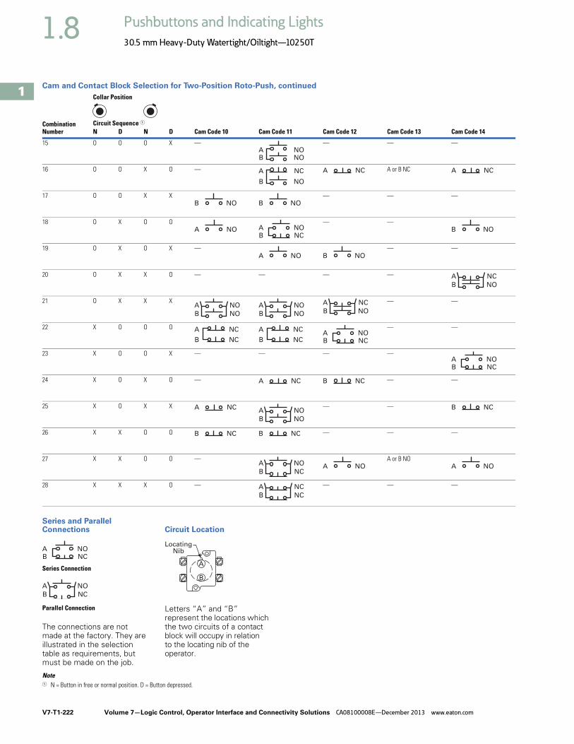
V7-T1-222 Volume 7—Logic Control, Operator Interface and Connectivity Solutions CA08100008E—December 2013 www.eaton.com
1
1
1
1
1
1
1
1
1
1
1
1
1
1
1
1
1
1
1
1
1
1
1
1
1
1
1
1
1
1
1.8 Pushbuttons and Indicating Lights
30.5 mm Heavy-Duty Watertight/Oiltight—10250T
Cam and Contact Block Selection for Two-Position Roto-Push, continued
Series and Parallel Connections
The connections are not made at the factory. They are illustrated in the selection table as requirements, but must be made on the job.
Circuit Location
Letters “A” and “B” represent the locations which the two circuits of a contact block will occupy in relation to the locating nib of the operator.
Note1 N = Button in free or normal position. D = Button depressed.
Combination Number
Collar Position
Cam Code 10 Cam Code 11 Cam Code 12 Cam Code 13 Cam Code 14Circuit Sequence 1
N D N D
15 O O O X — — — —
16 O O X O — A or B NC
17 O O X X — — —
18 O X O O — —
19 O X O X — — —
20 O X X O — — — —
21 O X X X — —
22 X O O O — —
23 X O O X — — — —
24 X O X O — — —
25 X O X X — —
26 X X O O — — —
27 X X O O — A or B NO
28 X X X O — — — —
B NOA NO
B NO
A NC A NC A NC
B NO B NO
A NOB NCA NO B NO
A NO B NO
B NO
A NC
B NO
A NO
B NO
A NOB NO
A NC
B NC
A NC
B NC
A NC
B NCA NO
B NCA NO
A NC B NC
A NC
B NO
A NOB NC
B NC B NC
B NC
A NO A NO A NO
B NC
A NC
Series Connection
Parallel Connection
B NCA NO
B NC
A NO
LocatingNib
A
B

Volume 7—Logic Control, Operator Interface and Connectivity Solutions CA08100008E—December 2013 www.eaton.com V7-T1-223
1
1
1
1
1
1
1
1
1
1
1
1
1
1
1
1
1
1
1
1
1
1
1
1
1
1
1
1
1
1
1.8Pushbuttons and Indicating Lights
30.5 mm Heavy-Duty Watertight/Oiltight—10250T
Cam and Contact Block Selection for Three-Position Roto-Push
Series and Parallel Connections
The connections are not made at the factory. They are illustrated in the selection table as requirements, but must be made on the job.
Circuit Location
Letters “A” and “B” represent the locations which the two circuits of a contact block will occupy in relation to the locating nib of the operator.
Notes1 N = Button in free or normal position. D = Button depressed.2 Limited to 4 contact blocks. See Note on Page V7-T1-236.
Combination Number
Collar Position
Cam Code 7 Cam Code 8 Cam Code 9 Cam Code 15 2 Cam Code 16 Cam Code 17 Cam Code 18Circuit Sequence 1
N D N D N D
1 O O O O O X — —
2 O O O O X X — — — — —
3 O O O X O O — — — — —
4 O O O X O X — — — — — —
5 O O O X X X — — — — — —
6 O O X X O O — — — — — —
7 O O X X O X — — — — — —
8 O O X X X O — — — — — —
9 O O X X X X — — — — — —
10 O X O O O O —
11 O X O O O X — — — —
12 O X O O X X — — — — — —
13 O X O X O O — — — — — —
14 O X O X O X — — — — — —
15 O X X X O O — — — — — —
16 O X X X O X — — — — — —
17 O X X X X X — — — — — —
B NOA NO
B NO
A NC
B NO
2
B NO B NO
A NC
B NO A NO
B NCA NO
B NOA NO
B NO
A NO
2
B NOA NO
B NO
B NO
A NC
B NO
B NCA NO
B NCA NO
A NO
2
A NO B NO B NCA NO
A NO B NO
A NO
B NO
A NO
B NO
A NO
A NO
B NO
A NO
A NO
B NO
A NO
B NO
A NO
Series Connection
Parallel Connection
B NCA NO
B NC
A NO
LocatingNib
A
B

V7-T1-224 Volume 7—Logic Control, Operator Interface and Connectivity Solutions CA08100008E—December 2013 www.eaton.com
1
1
1
1
1
1
1
1
1
1
1
1
1
1
1
1
1
1
1
1
1
1
1
1
1
1
1
1
1
1
1.8 Pushbuttons and Indicating Lights
30.5 mm Heavy-Duty Watertight/Oiltight—10250T
Cam and Contact Block Selection for Three-Position Roto-Push, continued
Series and Parallel Connections
The connections are not made at the factory. They are illustrated in the selection table as requirements, but must be made on the job.
Circuit Location
Letters “A” and “B” represent the locations which the two circuits of a contact block will occupy in relation to the locating nib of the operator.
Notes1 N = Button in free or normal position. D = Button depressed.2 Limited to 4 contact blocks. See Note on Page V7-T1-236.
Combination Number
Collar Position
Cam Code 7 Cam Code 8 2 Cam Code 9 Cam Code 15 Cam Code 16 Cam Code 17 Cam Code 18Circuit Sequence 1
N D N D N D
18 X O O O O O — — — — — —
19 X O O O X X — — — — — —
20 X O O O X O — — — — — —
21 X O X X O O — — — — — —
22 X O X X X X — —
23 X O X X X O — — — — —
24 X O X O X O — — — — —
25 X O X O X X — — — — —
26 X X O O O O — — — — —
27 X X O O O X — — — — — —
28 X X O O X O — — — — — —
29 X X O O X X — — — — —
30 X X X X O O — — — — —
31 X X X X X O — — —
32 X X X O X O — — — — —
33 X X X O X X — — — — —
B NC
A NC
A NC
B NC
A NC
B NC
A NC
B NO
A NC
B NO
A NC A NC B NC
B NO
A NC
A NC
B NC
A NC
B NC
A NC
B NC
A NC
2A NC A NC
B NC 2A NC
B NC
A NO
B NC
B NO
A NC
B NO
A NC
B NC A NC
B NC
A NC
B NC
A NO B NC
B NC
A NO
2
B NCB NC
B NC
A NOB NC
A NC
Series Connection
Parallel Connection
B NCA NO
B NC
A NO
LocatingNib
A
B

Volume 7—Logic Control, Operator Interface and Connectivity Solutions CA08100008E—December 2013 www.eaton.com V7-T1-225
1
1
1
1
1
1
1
1
1
1
1
1
1
1
1
1
1
1
1
1
1
1
1
1
1
1
1
1
1
1
1.8Pushbuttons and Indicating Lights
30.5 mm Heavy-Duty Watertight/Oiltight—10250T
AccessoriesPadlocks not included with padlocking attachments. For operators with built-in padlock attachment, see Page V7-T1-190.
Accessories
Description Catalog Number
Padlock Attachments
Padlocking Attachment for Flush Pushbutton OperatorsPermits locking NC contacts in open position with 1/4 in padlock. Will not lock NO contact.
10250TA2
Padlocking Attachment for Use with Extended PushbuttonPermits locking NC contacts in open position with 1/4 in padlock.
10250TA26
Padlocking Cover GuardCover locked over flush button makes it unaccessible or on extended button locks NC contacts open. Takes 1/4 in shank size padlock.
10250TA36
Padlock Hasp or Flip-Up GuardWhen used with a 1/4 in padlock, makes flush and long button and knob selector switch unaccessible, but not locked down. Without the padlock, it is a flip-up guard. Padlock hasp can be removed before assembly.
10250TA38
Padlocking Attachment for Use with Flexible Weather Resistant BootUsed on long button operators. Stainless steel. Use only for locking NC contacts open.
10250TA63
Padlock AttachmentFor use with illuminated pushbuttons and maintained push-pull operators having standard button or lens only. Use 1/4 in padlock. Locks in down position only.
10250TA64
Padlocking Attachment for Non-Illuminated Knob Selector SwitchesProvision for up to 5, 1/4 in padlocks.
10250TA11
10250TA2
10250TA26
10250TA36
10250TA38
10250TA63
10250TA64
10250TA11

V7-T1-226 Volume 7—Logic Control, Operator Interface and Connectivity Solutions CA08100008E—December 2013 www.eaton.com
1
1
1
1
1
1
1
1
1
1
1
1
1
1
1
1
1
1
1
1
1
1
1
1
1
1
1
1
1
1
1.8 Pushbuttons and Indicating Lights
30.5 mm Heavy-Duty Watertight/Oiltight—10250T
Accessories, continued
Notes1 Should not be used on flush button for STOP function.2 Not suitable for single contact block depth cast enclosure. Cover is too thick.
Description Catalog Number
Shrouds and Guards
Shroud for Mushroom Head OperatorPrevents accidental operation. (Not for push-pull operators.)
10250TA6
Extended Retaining NutReplaces standard nut and provides guard for flush head pushbutton operators.
10250TA12
Guard for Illuminated Pushbutton 10250TA15
ShroudFor jumbo mushroom head operator.
Gray 10250TA56
Yellow 10250TA56Y
Half Shroud—YellowFor jumbo mushroom head operator.
10250ED1241
Fingerproof Shroud—10 per packageFits new style contact blocks and light units.
10250TA101
Boots
Flexible Weather Resistant BootFor use with button operators (extended buttons preferred). Temperature to –25°F (–32°C).(See Page V7-T1-229 for 10250TA96 Tightening Tool.)
Black 10250TA3
Red 10250TA4 1
Green 10250TA10
Transparent BootFor regular illuminated pushbutton operators and PresTest—Temperature to –38°F (–39°C). 2
10250TA25
Boot for Flush Pushbutton
Clear 10250TA46
Black 10250TA47
Red 10250TA48
Green 10250TA49
10250TA6
10250TA12
10250TA15
10250TA56_
10250ED1241
10250TA101
10250TA_
10250TA25
10250TA4_
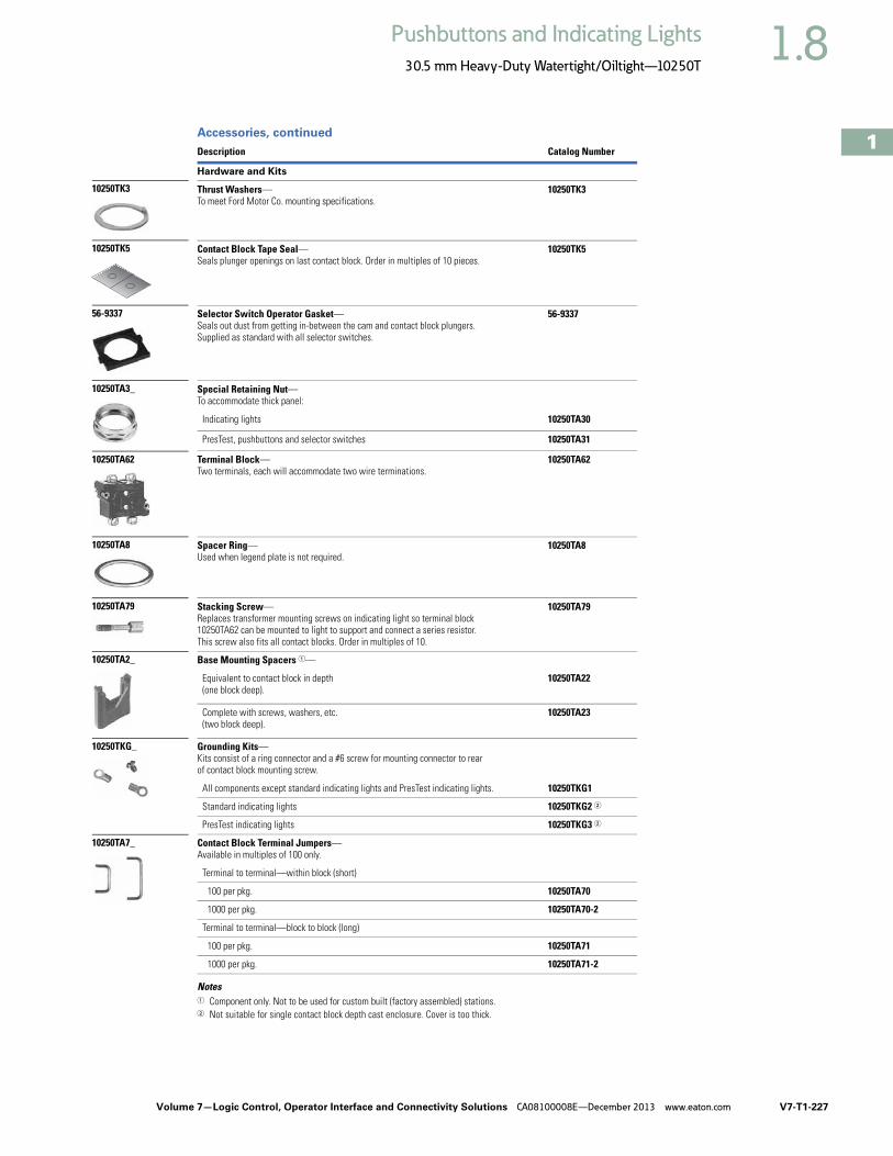
Volume 7—Logic Control, Operator Interface and Connectivity Solutions CA08100008E—December 2013 www.eaton.com V7-T1-227
1
1
1
1
1
1
1
1
1
1
1
1
1
1
1
1
1
1
1
1
1
1
1
1
1
1
1
1
1
1
1.8Pushbuttons and Indicating Lights
30.5 mm Heavy-Duty Watertight/Oiltight—10250T
Accessories, continued
Notes1 Component only. Not to be used for custom built (factory assembled) stations.2 Not suitable for single contact block depth cast enclosure. Cover is too thick.
Description Catalog Number
Hardware and Kits
Thrust Washers—To meet Ford Motor Co. mounting specifications.
10250TK3
Contact Block Tape Seal—Seals plunger openings on last contact block. Order in multiples of 10 pieces.
10250TK5
Selector Switch Operator Gasket—Seals out dust from getting in-between the cam and contact block plungers. Supplied as standard with all selector switches.
56-9337
Special Retaining Nut—To accommodate thick panel:
Indicating lights 10250TA30
PresTest, pushbuttons and selector switches 10250TA31
Terminal Block—Two terminals, each will accommodate two wire terminations.
10250TA62
Spacer Ring—Used when legend plate is not required.
10250TA8
Stacking Screw—Replaces transformer mounting screws on indicating light so terminal block 10250TA62 can be mounted to light to support and connect a series resistor. This screw also fits all contact blocks. Order in multiples of 10.
10250TA79
Base Mounting Spacers 1—
Equivalent to contact block in depth (one block deep).
10250TA22
Complete with screws, washers, etc.(two block deep).
10250TA23
Grounding Kits—Kits consist of a ring connector and a #6 screw for mounting connector to rear of contact block mounting screw.
All components except standard indicating lights and PresTest indicating lights. 10250TKG1
Standard indicating lights 10250TKG2 2
PresTest indicating lights 10250TKG3 2
Contact Block Terminal Jumpers—Available in multiples of 100 only.
Terminal to terminal—within block (short)
100 per pkg. 10250TA70
1000 per pkg. 10250TA70-2
Terminal to terminal—block to block (long)
100 per pkg. 10250TA71
1000 per pkg. 10250TA71-2
10250TA79
10250TK3
10250TK5
56-9337
10250TA3_
10250TA62
10250TA8
10250TA2_
10250TKG_
10250TA7_

V7-T1-228 Volume 7—Logic Control, Operator Interface and Connectivity Solutions CA08100008E—December 2013 www.eaton.com
1
1
1
1
1
1
1
1
1
1
1
1
1
1
1
1
1
1
1
1
1
1
1
1
1
1
1
1
1
1
1.8 Pushbuttons and Indicating Lights
30.5 mm Heavy-Duty Watertight/Oiltight—10250T
Accessories, continued
Note1 Not suitable for single contact block depth cast enclosure. Cover is too thick.
Description Catalog Number
Special Operators and Attachments
Wobble StickComplete with retaining nut—fits standard button.
10250TA5
Lever OperatorFor use with two vertically mounted flush pushbuttons.
10250TA14
Maintained Contact Attachment Release Button Assembly 1Mechanically interlocks with another pushbutton and contact block (not included).Provides mode indication. Minimum hole centers 1.62 in (41.1 mm), maximum 2.313 in (58.8 mm).
Black 10250TA17
Red 10250TA18
Green 10250TA19
Yellow 10250TA20
Same with Long Button—Black 10250TA39
Maintained Contact Attachment 1Mechanically interlocks two buttons and provides position indication for one. Use with two pushbutton operators and one or more contact blocks.
10250TA1
Roto-Push Lever Operator—Used to provide lever operation for Roto-Push operators.
10250TA13
Special Light Modules
Master Test (Dual Input) Module—Internal Form C relay suitable for either AC or DC applications. Total electrical isolation between monitored and test circuit. Fits all illuminated 10250T, E22, E30 and E34 devices.
48 Vdc 10250TMT8
Flasher Module—Changes any AC illuminated device to a controlled flashing light. Fits 10250T, E30 and E34 devices.
24V 10250TFL2
120V 10250TFL1
Flashing Incandescent Lamp—For use with 120V transformer type or 6V full voltage type indicating lights including PresTest and most E29 devices.
10250ED986-4
10250TA5
10250TA14
10250TA_
10250TA1
10250TA13
10250TA79
10250TFL_
10250ED986-4

Volume 7—Logic Control, Operator Interface and Connectivity Solutions CA08100008E—December 2013 www.eaton.com V7-T1-229
1
1
1
1
1
1
1
1
1
1
1
1
1
1
1
1
1
1
1
1
1
1
1
1
1
1
1
1
1
1
1.8Pushbuttons and Indicating Lights
30.5 mm Heavy-Duty Watertight/Oiltight—10250T
Accessories, continued
Description Catalog Number
Hole Plugs
Plug—For unused holes—steel, painted gray (stainless steel, use E30KT5, see Page V7-T1-175)
10250TA7
Tools
Octagonal 10250T (notched to fit over selector switch lever), E29 and E30 10250TA95
E22, E30, E34 and octagonal 10250T (will not fit over selector switch levers) E22CW
Tool for Tightening Boots—Used to install boot Catalog Numbers 10250TA3, A4, A10 and A25.
10250TA96
10250T, E34 Allen Wrench—Used for removal of jumbo mushroom head.
10250TA102
Lamp Removal Tools—For transformer type illuminated pushbuttons, push-pull and selector switches. Fits #12 lamp.
10250TA74
For full voltage and resistor type illuminated pushbuttons, push-pull and selector switches and E30.
E30KV1
Standard indicating lights. Fits #44, #755, #6S6 and #10S6. E29KLT
10250TA7
10250TA95
E22CW
10250TA96
10250TA102
10250TA74
E30KV1
E29KLT
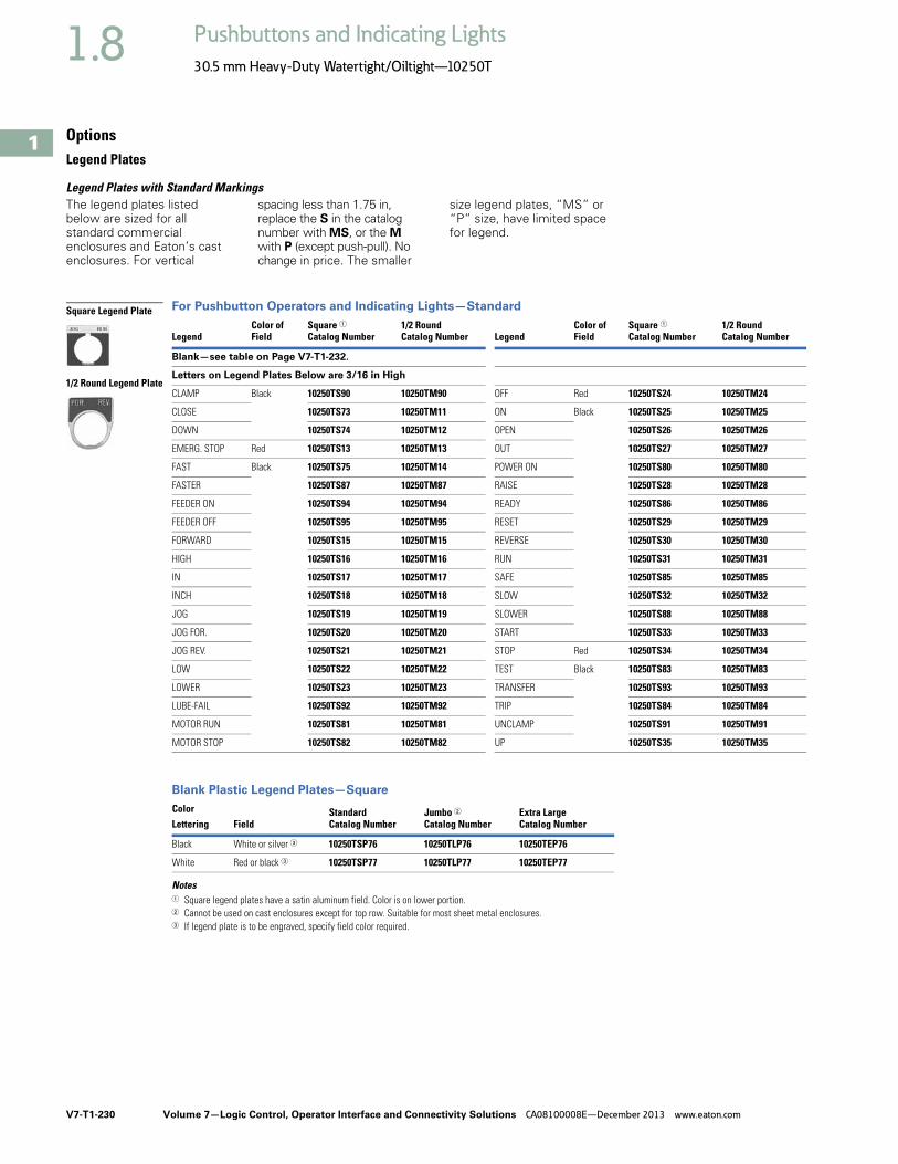
V7-T1-230 Volume 7—Logic Control, Operator Interface and Connectivity Solutions CA08100008E—December 2013 www.eaton.com
1
1
1
1
1
1
1
1
1
1
1
1
1
1
1
1
1
1
1
1
1
1
1
1
1
1
1
1
1
1
1.8 Pushbuttons and Indicating Lights
30.5 mm Heavy-Duty Watertight/Oiltight—10250T
OptionsLegend Plates
Legend Plates with Standard MarkingsThe legend plates listed below are sized for all standard commercial enclosures and Eaton’s cast enclosures. For vertical
spacing less than 1.75 in, replace the S in the catalog number with MS, or the M with P (except push-pull). No change in price. The smaller
size legend plates, “MS” or “P” size, have limited space for legend.
For Pushbutton Operators and Indicating Lights—Standard
Blank Plastic Legend Plates—Square
Notes1 Square legend plates have a satin aluminum field. Color is on lower portion.2 Cannot be used on cast enclosures except for top row. Suitable for most sheet metal enclosures.3 If legend plate is to be engraved, specify field color required.
LegendColor ofField
Square 1Catalog Number
1/2 RoundCatalog Number Legend
Color ofField
Square 1Catalog Number
1/2 RoundCatalog Number
Blank—see table on Page V7-T1-232.
Letters on Legend Plates Below are 3/16 in High
CLAMP Black 10250TS90 10250TM90 OFF Red 10250TS24 10250TM24
CLOSE 10250TS73 10250TM11 ON Black 10250TS25 10250TM25
DOWN 10250TS74 10250TM12 OPEN 10250TS26 10250TM26
EMERG. STOP Red 10250TS13 10250TM13 OUT 10250TS27 10250TM27
FAST Black 10250TS75 10250TM14 POWER ON 10250TS80 10250TM80
FASTER 10250TS87 10250TM87 RAISE 10250TS28 10250TM28
FEEDER ON 10250TS94 10250TM94 READY 10250TS86 10250TM86
FEEDER OFF 10250TS95 10250TM95 RESET 10250TS29 10250TM29
FORWARD 10250TS15 10250TM15 REVERSE 10250TS30 10250TM30
HIGH 10250TS16 10250TM16 RUN 10250TS31 10250TM31
IN 10250TS17 10250TM17 SAFE 10250TS85 10250TM85
INCH 10250TS18 10250TM18 SLOW 10250TS32 10250TM32
JOG 10250TS19 10250TM19 SLOWER 10250TS88 10250TM88
JOG FOR. 10250TS20 10250TM20 START 10250TS33 10250TM33
JOG REV. 10250TS21 10250TM21 STOP Red 10250TS34 10250TM34
LOW 10250TS22 10250TM22 TEST Black 10250TS83 10250TM83
LOWER 10250TS23 10250TM23 TRANSFER 10250TS93 10250TM93
LUBE-FAIL 10250TS92 10250TM92 TRIP 10250TS84 10250TM84
MOTOR RUN 10250TS81 10250TM81 UNCLAMP 10250TS91 10250TM91
MOTOR STOP 10250TS82 10250TM82 UP 10250TS35 10250TM35
Color StandardCatalog Number
Jumbo 2Catalog Number
Extra LargeCatalog NumberLettering Field
Black White or silver 3 10250TSP76 10250TLP76 10250TEP76
White Red or black 3 10250TSP77 10250TLP77 10250TEP77
Square Legend Plate
1/2 Round Legend Plate

Volume 7—Logic Control, Operator Interface and Connectivity Solutions CA08100008E—December 2013 www.eaton.com V7-T1-231
1
1
1
1
1
1
1
1
1
1
1
1
1
1
1
1
1
1
1
1
1
1
1
1
1
1
1
1
1
1
1.8Pushbuttons and Indicating Lights
30.5 mm Heavy-Duty Watertight/Oiltight—10250T
For Selector Switch and Roto-Push Operators—Standard Size
45 mm and 70 mm Plastic—Round
For Push-Pull Units 3
Notes1 Square legend plates have a satin aluminum field. Color is on lower portion.2 If legend plate is to be engraved, specify field color required.3 All push-pull legend plates include the symbols in the center of the plate.
LegendColor ofField
Square 1Catalog Number
1/2 RoundCatalog Number Legend
Color ofField
Square 1Catalog Number
1/2 RoundCatalog Number
Blank—see table on Page V7-T1-232.
2-Position—5/32 in High Lettering 3-Position—1/8 in High Lettering
FOR. REV. Black 10250TS38 10250TM38 AUTO OFF HAND Black 10250TS49 10250TM49
HAND AUTO 10250TS39 10250TM39 FOR. OFF REV. 10250TS50 10250TM50
HIGH LOW 10250TS40 10250TM40 FOR. SAFE REV. 10250TS69 10250TM69
JOG RUN 10250TS41 10250TM41 HAND OFF AUTO 10250TS51 10250TM51
MAN. AUTO 10250TS67 10250TM67 MAN. OFF AUTO 10250TS68 10250TM68
OFF ON 10250TS42 10250TM42 OPEN OFF CLOSE 10250TS53 10250TM53
OPEN CLOSE 10250TS43 10250TM43 RUN SAFE JOG 10250TS70 10250TM70
RUN JOG 10250TS44 10250TM44 UP OFF DOWN 10250TS54 10250TM54
SAFE RUN 10250TS45 10250TM45 ON STOP SAFE Red 10250TS71 10250TM71
START JOG 10250TS46 10250TM46
START STOP 10250TS47 10250TM47
UP DOWN 10250TS48 10250TM48
ColorLettering Field Catalog Number
45 mm
Blank Yellow or red 2 10250TRP78
70 mm
Blank Yellow or red 2 10250TRP76
Red EMERG. STOP Yellow 10250TRP79
LegendColor ofField
Square 1Catalog Number
1/2 RoundCatalog Number
Standard Size—Letters on Legend Plates Below are 3/32 in High
PULL START/PUSH STOP Green/red 10250TPP2 10250TR2
PUSH ON/PULL OFF Black 10250TPP5 10250TR5
PULL OPEN/PUSH CLOSE Black 10250TPP8 10250TR8
PULL UP/PUSH DOWN Black 10250TPP11 10250TR11
Jumbo Size—Letters on Legend Plates Below are 1/8 in High
PULL START/PUSH STOP Green/red 10250TPP3 10250TR3
PULL ON/PUSH OFF Black 10250TPP6 10250TR6
PULL OPEN/PUSH CLOSE Black 10250TPP9 10250TR9
PULL UP/PUSH DOWN Black 10250TPP12 10250TR12
Square Legend Plate
1/2 Round Legend Plate
70 mm Round—Plastic Legend Plate

V7-T1-232 Volume 7—Logic Control, Operator Interface and Connectivity Solutions CA08100008E—December 2013 www.eaton.com
1
1
1
1
1
1
1
1
1
1
1
1
1
1
1
1
1
1
1
1
1
1
1
1
1
1
1
1
1
1
1.8 Pushbuttons and Indicating Lights
30.5 mm Heavy-Duty Watertight/Oiltight—10250T
Legend Plates with Non-Standard MarkingsWhen Ordering Specify
● Catalog number of blank plate phase plus Suffix “STAMP.”
● Insert the following into Order Notes: legend, letter size and locations (letters A–W)—combine letters for definitive locations as shown.
Ordering Example:
Catalog No.: 10250TS36STAMPLetter Size: 3/32 in (2.4 mm)Pos. A—POWER HOUSEPos. B—START PUMP 1
Legend Characters Available
A B C D E F G H I J K L M N O P Q R S T U V W X Y Z / - . , 1 2 3 4 5 6 7 8 9 0
Legend characters on black and red plates are white—on satin aluminum plates, characters are black.
Blackening Kit
Solution blackens aluminum exposed by engraving process. Must be applied immediately after engraving. 0.3 oz. bottle—sufficient for approximately 1100 legend plates.
Catalog Number: 10250TBK
Legend Positions
Blank and Custom Engraved Legend Plates
Maximum Characters per Legend Plate and Approximate Dimensions
Notes1 All push-pull legend plates include the symbols in the center of the plate.2 Cannot be used on cast enclosures except for top row. Suitable for most sheet metal enclosures.3 When used to meet Ford Motor Co. specifications, specify engraved legend. Cannot be used on standard cast or sheet metal enclosures.4 Slightly larger than standard size for legends requiring more space—fits cast enclosures.5 Square legend plates have a satin aluminum field. Color is on lower portion.6 Recommended only when mounting on minimum centers (less than 1-3/4 in [44.5 mm] vertical centers).7 Can be used on top row only of any enclosure.
Style ColorSmallCatalog Number
StandardCatalog Number
Jumbo 2Catalog Number
Extra Large 3Catalog Number
Four-Position Selector Switch Push-Pull with Symbols 1
Custom 4Catalog Number
StandardCatalog Number
StandardCatalog Number
Jumbo 2Catalog Number
Square 5 Black 10250TMS36 10250TS36 10250TL36 — 10250TS76 10250TS72 10250TPP17 10250TPP18
Red 10250TMS37 10250TS37 10250TL37 — — — — —
Green/red — — — — — — 10250TPP20 10250TPP21
Satin alum. — — — 10250TNP99 — — — —
1/2 Round Black 10250TP36 10250TM36 10250TJ36 — — 10250TM72 10250TR17 10250TR18
Red 10250TP37 10250TM37 10250TJ37 — — — — —
Green/red — — — — — — 10250TR20 10250TR21
Satin alum. — 10250TM89 10250TJ89 — — — — —
Top(Aluminumand Plastic) Style
Character SizeApproximate Dimensions in Inches (mm)
3/32 in High 1/8 in High 3/16 in HighNumberof Lines
Number ofCharacters
Numberof Lines
Number ofCharacters
Numberof Lines
Number ofCharactersWidth Height
Small 6 1.59 (40.4) 1.59 (40.4) Square 1 17 — — — —
1/2 Round 1 15 1 12 1 9
Standard andcustom
1.75 (44.5) 1.75 (44.5) Square 2 18 2 13 1 9
1/2 Round 2 15 2 12 1 9
Jumbo 7 2.19 (55.6) 2.19 (55.6) Square 5 23 3 18 2 12
1/2 Round 5 19 4 15 2 11
Extra large 3 2.44 (62) 2.44 (62) Square 6 25 3 18 3 12
L
K
D
C
B
A
Extra Large SizeCat. No. 10250TNP99
Jumbo Size10250TL or TJ Series
Small Size10250TMS or TP Series
A
A
C
K
D
B
Standard Size10250TS or TM Series
AB
B
A
G F
AE
G H
A
I
AF
D4
C4B4
A4

Volume 7—Logic Control, Operator Interface and Connectivity Solutions CA08100008E—December 2013 www.eaton.com V7-T1-233
1
1
1
1
1
1
1
1
1
1
1
1
1
1
1
1
1
1
1
1
1
1
1
1
1
1
1
1
1
1
1.8Pushbuttons and Indicating Lights
30.5 mm Heavy-Duty Watertight/Oiltight—10250T
Enclosures
Die Cast, Polyester and Stainless Steel Enclosures
Enclosures (Case and Cover)—Surface Mounting 1
Mounting InstructionsTwo-position joystick must be used with two contact block deep enclosures (maximum number of contact blocks = 1). Four-position joysticks cannot be used within these enclosures.
One and Two Contact Block Depth Enclosures Enclosure Layouts
Notes1 For spacing increments, see Page V7-T1-234.2 All die cast enclosures can be converted to base mounting of contact blocks, with spacers 10250TA22 or 10250TA23.
See listing on Page V7-T1-227.3 When used with E30 pushbuttons, only the one element enclosure can be used.4 When used with resistor light units, only the 2 contact block depth enclosure can be used.5 14 gauge, type 304.
Number ofElements
One Contact Block DepthCatalog Number
Two Contact Block DepthCatalog Number
Die Cast Enclosure—In-Line 234 NEMA 4, 4X, 12, 13
1 10250TN1 10250TN11
2 10250TN2 10250TN12
3 10250TN3 10250TN13
4 — 10250TN14
Polyester4—In-Line NEMA 3, 4X, 12
1 — E34N51
2 — E34N52
3 — E34N53
4 — E34N54
Stainless Steel 45—In-Line NEMA 4, 4X, 12
1 — 10250TN33
2 — 10250TN34
3 — 10250TN35
4 — 10250TN36
Dimensions, see Page V7-T1-246.
Die Cast Enclosure
Polyester Enclosure
Stainless Steel Enclosure
One Contact Block Depth Enclosure
Two Contact Block Depth Enclosure
1 1 1
Top – For Vertical Mounting
To
p –
Fo
r Ho
rizon
tal
Mo
un
ting
1
2 2 2
3 3
4
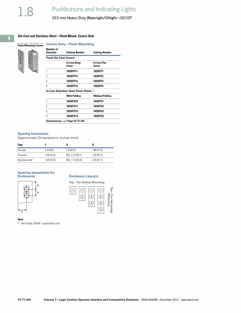
V7-T1-234 Volume 7—Logic Control, Operator Interface and Connectivity Solutions CA08100008E—December 2013 www.eaton.com
1
1
1
1
1
1
1
1
1
1
1
1
1
1
1
1
1
1
1
1
1
1
1
1
1
1
1
1
1
1
1.8 Pushbuttons and Indicating Lights
30.5 mm Heavy-Duty Watertight/Oiltight—10250T
Die Cast and Stainless Steel—Flush Mount, Covers Only
Covers Only—Flush Mounting
Spacing Increments
Approximate Dimensions in Inches (mm)
Spacing Increments for Enclosures Enclosure Layouts
Note1 Not oiltight. NEMA 1 applications only.
Number ofElements Catalog Number Catalog Number
Flush Die Cast Covers
In-Line Deep Cover
In-Line Flat Cover
1 10250TF11 10250TF1
2 10250TF12 10250TF2
3 10250TF13 10250TF3
4 10250TF14 10250TF4
In-Line Stainless Steel Flush Plates 1
With Pullbox Without Pullbox
1 10250TS10 10250TS1
2 10250TS11 10250TS2
3 10250TS12 10250TS3
4 10250TS14 10250TS4
Dimensions, see Page V7-T1-247.
Type F G H
Die cast 2.44 (62) 2.5 (63.5) 1.88 (47.8)
Polyester 1.88 (47.8) Min. 2.13 (54.1) 2.25 (57.2)
Stainless steel 1.69 (42.9) Min. 1.73 (43.9) 2.25 (57.2)
Flush Mounting Covers
F
G
H1 1 1
Top – For Vertical Mounting
To
p –
Fo
r Ho
rizon
tal
Mo
un
ting
1
2 2 2
3 3
4

Volume 7—Logic Control, Operator Interface and Connectivity Solutions CA08100008E—December 2013 www.eaton.com V7-T1-235
1
1
1
1
1
1
1
1
1
1
1
1
1
1
1
1
1
1
1
1
1
1
1
1
1
1
1
1
1
1
1.8Pushbuttons and Indicating Lights
30.5 mm Heavy-Duty Watertight/Oiltight—10250T
Contact Blocks
Standard Contact Blocks● UL A600/P600 rated● Color-coded plungers—red/
green for NC/NO circuits● Silver contact tips with
“reliability nibs”● Gray (opaque) or amber
(translucent) housings● Pressure plate or spade
terminals● Fingerproof shrouds (for
pressure terminals only)
Logic Level Contact Blocks● UL A600/P600 rated● Color-coded plungers● Inert palladium knife-blade
contacts ● Gray (opaque) housings● Pressure plate or spade
terminals
Special Function Contact Blocks● UL A600/P600 rated● Color-coded plungers● Silver contact tips with
“reliability nibs”● Gray (opaque) housings● Pressure plate terminals
only
Special Purpose Contact Block● Maximum 300V rated● Black plungers● Silver contact tips with
“reliability nibs”● Black (opaque) housings● Pressure plate terminals
only● Fingerproof shrouds not
available
Reliability NibsReliability nibs are the hallmark of Eaton’s contact blocks. A pointed silver nib on the contact tip ensures reliable switching from logic level (5V) up to 600V applications. Therefore standard contact blocks can be used for most logic level applications where the contacts are not exposed to any harsh environmental conditions.
Palladium ContactsPalladium, which is more inert than gold, is well suited for voltages and currents approaching zero and is recommended for applications where environmental conditions are a factor.
Maximum Contact Block Mounting per Operator Type
OperatorMax. Stack
Pushbuttons 6
Push-pull operators 2
Roto-push operators 4
Two- or three-position selector switches
6
Four-position selector switches
4
Joysticks 4

V7-T1-236 Volume 7—Logic Control, Operator Interface and Connectivity Solutions CA08100008E—December 2013 www.eaton.com
1
1
1
1
1
1
1
1
1
1
1
1
1
1
1
1
1
1
1
1
1
1
1
1
1
1
1
1
1
1
1.8 Pushbuttons and Indicating Lights
30.5 mm Heavy-Duty Watertight/Oiltight—10250T
Contact Blocks
Notes1 All 10250T contact blocks shown are suitable for use on standard 10250T and E34 operators. These contact blocks are not suitable for Class I Division 2
type 10250T or E34 devices.2 Contact blocks with spade terminals are limited to a maximum of one contact block per operator and minimum spacing between devices is 2.5 in (63.5 mm).
Not suitable for use in 10250T or E34 enclosures. Also available in amber housing. Not available with fingerproof shrouds.3 Special function contact blocks are not suitable for use with roto-push operators, three-position push-pull operators, or four-position selector switches.4 ECNO contact blocks are not suitable for use with two-position joysticks or when operators are used with padlock attachments.5 Special purpose 10250T44 contact blocks are not suitable on selector switches or roto-push operators. Okay to use with three-position push-pull operators only
on low voltage (30V or less) circuits. Fingerproof shrouds not available.
Symbol Circuit Description 1
Standard Logic LevelPressure TerminalCatalog Number
Spade Terminal 2Catalog Number
Pressure TerminalCatalog Number
Spade Terminal 2Catalog Number
1NC Stack up to six blocks (six circuits) unless otherwise noted.
10250T51 10250T59 10250T51E 10250T59E
1NO Stack up to six blocks six circuits) unless otherwise noted.
10250T53 10250T60 10250T53E 10250T60E
NO-NC Stack up to six blocks (12 circuits) unless otherwise noted.
10250T1 10250T40 10250T1E 10250T40E
2NC Stack up to six blocks (12 circuits) unless otherwise noted.
10250T3 10250T42 10250T3E 10250T42E
2NO Stack up to six blocks (12 circuits) unless otherwise noted.
10250T2 10250T41 10250T2E 10250T41E
Special Function Blocks 3
LONC Late opening NC. Stack up to six blocks (six circuits) unless otherwise noted.
10250T71 3 — 10250T71E 3 —
ECNO-NC
Early closing NO and standard NC. Stack up to six blocks unless otherwise noted.
10250T47 34 — 10250T47E 3 —
ECNO-NO
Early closing NO and standard NO. Stack up to four blocks unless otherwise noted.
10250T57 34 — 10250T57E 3 —
2LONC Two late opening NC contacts. Stack up to six blocks unless otherwise noted.
10250T45 3 — 10250T45E 3 —
LONC-ECNO
Overlapping contacts. Stack up to four blocks unless otherwise noted.
10250T55 34 — 10250T55E 3 —
Special Purpose Blocks 5
2NO-2NC
Four circuits in single block depth. Rated 300V max. Stack up to four blocks unless otherwise noted.
10250T44 5 —
10250T1
BlankNo
Plunger
BlankNo
Plunger
BlankNo
Plunger

Volume 7—Logic Control, Operator Interface and Connectivity Solutions CA08100008E—December 2013 www.eaton.com V7-T1-237
1
1
1
1
1
1
1
1
1
1
1
1
1
1
1
1
1
1
1
1
1
1
1
1
1
1
1
1
1
1
1.8Pushbuttons and Indicating Lights
30.5 mm Heavy-Duty Watertight/Oiltight—10250T
Contact Blocks with Fingerproof Shrouds
Notes1 All 10250T contact blocks shown are suitable for use on standard 10250T and E34 operators. These contact blocks are not suitable for Class I Division 2
type 10250T or E34 devices.2 To order contact blocks with translucent amber housing, change suffix P to CP in catalog number e.g. 10250T51CP.3 ECNO contact blocks are not suitable for use with two-position joysticks or when operators are used with padlock attachments.4 Special function contact blocks are not suitable for use with roto-push operators, three-position push-pull operators, or four-position selector switches.
Symbol Circuit Description 1
StandardPressure Terminal 2Catalog Number
Logic LevelPressure Terminal 2Catalog Number
1NC Stack up to six blocks (six circuits) unless otherwise noted. 10250T51P 10250T51EP
1NO Stack up to six blocks (six circuits) unless otherwise noted. 10250T53P 10250T53EP
NO-NC Stack up to six blocks (12 circuits) unless otherwise noted. 10250T1P 10250T1EP
2NC Stack up to six blocks (12 circuits) unless otherwise noted. 10250T3P 10250T3EP
2NO Stack up to six blocks (12 circuits) unless otherwise noted. 10250T2P 10250T2EP
Special Function Blocks 3
LONC Late opening NC. Stack up to six blocks (six circuits) unless otherwise noted.
10250T71P 4 10250T71EP 4
ECNO-NC Early closing NO and standard NC. Stack up to six blocks unless otherwise noted.
10250T47P 34 10250T47EP 4
ECNO-NO Early closing NO and standard NO. Stack up to four blocks unless otherwise noted.
10250T57P 34 10250T57EP 4
2LONC Two late opening NC contacts. Stack up to six blocks unless otherwise noted.
10250T45P 4 10250T45EP 4
LONC-ECNO Overlapping contacts. Stack up to four blocks unless otherwise noted.
10250T55P 34 10250T55EP 4
10250T1CP
BlankNo
Plunger
BlankNo
Plunger
BlankNo
Plunger

V7-T1-238 Volume 7—Logic Control, Operator Interface and Connectivity Solutions CA08100008E—December 2013 www.eaton.com
1
1
1
1
1
1
1
1
1
1
1
1
1
1
1
1
1
1
1
1
1
1
1
1
1
1
1
1
1
1
1.8 Pushbuttons and Indicating Lights
30.5 mm Heavy-Duty Watertight/Oiltight—10250T
Amber Contact Blocks
Notes1 All 10250T contact blocks shown are suitable for use on standard 10250T and E34 operators. These contact blocks are not suitable for Class I Division 2
type 10250T or E34 devices.2 To order amber contact blocks with fingerproof shrouds, change suffix to CP in the catalog number e.g. 10250T51CP. Not available with spade terminals.3 Contact blocks with spade terminals are limited to a maximum of one contact block per operator and minimum spacing between devices is 2.5 in (63.5 mm).
Not suitable for use in 10250T or E34 enclosures. Also available in amber housing. Not available with fingerproof shrouds.4 Special function contact blocks are not suitable for use with roto-push operators, three-position push-pull operators, or four-position selector switches.5 ECNO contact blocks are not suitable for use with two-position joysticks or when operators are used with padlock attachments.
Symbol Circuit Description 1
Standard Logic LevelPressure Terminal 2Catalog Number
Spade Terminal 3Catalog Number
Pressure Terminal 2Catalog Number
Spade Terminal 3Catalog Number
1NC Stack up to six blocks (six circuits) unless otherwise noted.
10250T51C 10250T59C 10250T51EC 10250T59EC
1NO Stack up to six blocks (six circuits) unless otherwise noted.
10250T53C 10250T60C 10250T53EC 10250T60EC
NO-NC Stack up to six blocks (12 circuits) unless otherwise noted.
10250T1C 10250T40C 10250T1EC 10250T40EC
2NC Stack up to six blocks (12 circuits) unless otherwise noted.
10250T3C 10250T42C 10250T3EC 10250T42EC
2NO Stack up to six blocks (12 circuits) unless otherwise noted.
10250T2C 10250T41C 10250T2EC 10250T41EC
Special Function Blocks 3
LONC Late opening NC. Stack up to six blocks (six circuits) unless otherwise noted.
10250T71C 4 — 10250T71EC 4 —
ECNO-NC
Early closing NO and standard NC. Stack up to six blocks unless otherwise noted.
10250T47C 45 — 10250T47EC 4 —
ECNO-NO
Early closing NO and standard NO. Stack up to four blocks unless otherwise noted.
10250T57C 45 — 10250T57EC 4 —
2LONC Two late opening NC contacts. Stack up to six blocks unless otherwise noted.
10250T45C 4 — 10250T45EC 4 —
LONC-ECNO
Overlapping contacts. Stack up to four blocks unless otherwise noted.
10250T55C 45 — 10250T55EC 4 —
10250T1C
BlankNo
Plunger
BlankNo
Plunger
BlankNo
Plunger
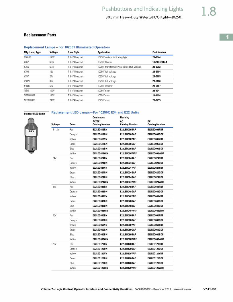
Volume 7—Logic Control, Operator Interface and Connectivity Solutions CA08100008E—December 2013 www.eaton.com V7-T1-239
1
1
1
1
1
1
1
1
1
1
1
1
1
1
1
1
1
1
1
1
1
1
1
1
1
1
1
1
1
1
1.8Pushbuttons and Indicating Lights
30.5 mm Heavy-Duty Watertight/Oiltight—10250T
Replacement Parts
Replacement Lamps—For 10250T Illuminated Operators
Replacement LED Lamps—For 10250T, E34 and E22 Units
Mfg. Lamp Type Voltage Base Style Application Part Number
120MB 120V T 3-1/4 bayonet 10250T resistor indicating light 28-3044
#267 6.3V T 3-1/4 bayonet 10250T flasher 10250ED986-4
#755 6.3V T 3-1/4 bayonet 10250T transformer, PresTest and full voltage 28-2202
#756 12V T 3-1/4 bayonet 10250T full voltage 28-5184
#757 24V T 3-1/4 bayonet 10250T full voltage 28-5185
#1828 32V T 3-1/4 bayonet 10250T full voltage 28-5186
#1835 55V T 3-1/4 bayonet 10250T resistor 28-5187
NE48 120V T 4-1/2 bayonet 10250T neon 28-494
NE51H-R22 120V T 3-1/4 bayonet 10250T neon 28-3754
NE51H-R68 240V T 3-1/4 bayonet 10250T neon 28-3755
Voltage Color
Continuous FlashingAC/DCCatalog Number
ACCatalog Number
DCCatalog Number
6–12V Red E22LED612RN E22LED006RAF E22LED006RDF
Orange E22LED612ON E22LED006OAF E22LED006ODF
Yellow E22LED612YN E22LED006YAF E22LED006YDF
Green E22LED612GN E22LED006GAF E22LED006GDF
Blue E22LED612BN E22LED006BAF E22LED006BDF
White E22LED612WN E22LED006WAF E22LED006WDF
24V Red E22LED024RN E22LED024RAF E22LED024RDF
Orange E22LED024ON E22LED024OAF E22LED024ODF
Yellow E22LED024YN E22LED024YAF E22LED024YDF
Green E22LED024GN E22LED024GAF E22LED024GDF
Blue E22LED024BN E22LED024BAF E22LED024BDF
White E22LED024WN E22LED024WAF E22LED024WDF
48V Red E22LED048RN E22LED048RAF E22LED048RDF
Orange E22LED048ON E22LED048OAF E22LED048ODF
Yellow E22LED048YN E22LED048YAF E22LED048YDF
Green E22LED048GN E22LED048GAF E22LED048GDF
Blue E22LED048BN E22LED048BAF E22LED048BDF
White E22LED048WN E22LED048WAF E22LED048WDF
60V Red E22LED060RN E22LED060RAF E22LED060RDF
Orange E22LED060ON E22LED060OAF E22LED060ODF
Yellow E22LED060YN E22LED060YAF E22LED060YDF
Green E22LED060GN E22LED060GAF E22LED060GDF
Blue E22LED060BN E22LED060BAF E22LED060BDF
White E22LED060WN E22LED060WAF E22LED060WDF
120V Red E22LED120RN E22LED120RAF E22LED120RDF
Orange E22LED120ON E22LED120OAF E22LED120ODF
Yellow E22LED120YN E22LED120YAF E22LED120YDF
Green E22LED120GN E22LED120GAF E22LED120GDF
Blue E22LED120BN E22LED120BAF E22LED120BDF
White E22LED120WN E22LED120WAF E22LED120WDF
Standard LED Lamp

V7-T1-240 Volume 7—Logic Control, Operator Interface and Connectivity Solutions CA08100008E—December 2013 www.eaton.com
1
1
1
1
1
1
1
1
1
1
1
1
1
1
1
1
1
1
1
1
1
1
1
1
1
1
1
1
1
1
1.8 Pushbuttons and Indicating Lights
30.5 mm Heavy-Duty Watertight/Oiltight—10250T
10250T Style Operator Replacement Parts
Two-Position Joystick Operator
Flush Head Pushbutton Operator
Mushroom HeadPushbutton Operator
Four-Position Joystick Operator (without Latch)
Illuminated Pushbutton Operator
Full Voltage, Resistor and Transformer TypeIlluminated Selector Switch
Transformer TypeIndicating Light
Mushroom HeadOperator withPadlock Attachment
Jumbo Mushroom Head Operator
Knob-OperatedSelector SwitchOperator
Potentiometers
ItemNo. Description
No.Req. Part Number
1 Gasket 1 16-1548
2 Mounting nut 1 15-1530
3 Handle 1 24-5045
4 Knob 1 53-3157
Knob (not shown) for joystick operator with latch 1 53-3159
5 Common gate (supplied with operator) 2 16-3400
6 Set screw (#6-32 x 0.250 in long hollow hex) 2 11-2014
7 Mushroom head button (includes [2] Item 6) 1 As Req. Below
Black — 53-1317
Red — 53-1317-2
Yellow — 53-1317-3
Green — 53-1317-4
Blue — 53-1317-22
8 Set screw (#10-32 x 0.250 in long hollow hex) 2 11-544
9 Jumbo mushroom head button (aluminum—includes [2] Item 8)
1 As Req. Below
Red — 53-1317-9
Black — 53-1317-10
Yellow — 53-1317-11
Green — 53-1317-12
10 Jumbo mushroom head button (aluminum—red EMERG. STOP)does not include Item 8
1 53-1349-18
11 Position gate:
Two-position 1 54-7278
Three-position 1 54-7173
Four-position 1 54-12278
Eight-position 1 54-12279
12 Mounting screw (#6-32 x 0.710 in long) 2 10250TA79
Washer 2 16-2038
13 Terminal screw and lug (captive) Req. 80-5502KIT
ItemNo. Description
No.Req. Part Number
14 Gasket (supplied with basic unit) 1 32-803
15 Round head screw (#4-40 x 0.344 in long) (supplied with basic unit)
2 11-4553
16 Mounting screw 2 11-1632
17 Simple potentiometer (does not include items 18, 28 or 29)
1 As Req. Below
1,000 ohms — 41-782-2
2,500 ohms — 41-782-3
5,000 ohms — 41-782-10
10,000 ohms — 41-782-4
25,000 ohms — 41-782-5
50,000 ohms — 41-782-6
18 Connector (includes screw and lug) 2 25-1851
19 Indicating plate 1 As Req. Above
Standard size (without legend) — 30-4460
Large size (specify legend) — 10250TR30
20 Retaining nut 1 15-1547
21 Knob 1 53-1314
Socket set screw (#6-32 x 0.250 in long) 2 11-2014
22 Coupling 1 29-3749-2
23 Set screw (#6-32 x 0.188 in long) 1 11-1199
24 Spacer 2 56-1066-18
25 Connector (includes screw and lug) 1 25-1851-2
26 Mounting nut 1 15-1938
27 Four-position joystick operating mechanism(complete)
1 24-6565
28 Four-position joystick operating mechanism (not shown) (with latch) complete
1 24-6565-2
29 Spring loaded latch 1 52-1214-2
30 Hand operated latch 1 52-913-3

Volume 7—Logic Control, Operator Interface and Connectivity Solutions CA08100008E—December 2013 www.eaton.com V7-T1-241
1
1
1
1
1
1
1
1
1
1
1
1
1
1
1
1
1
1
1
1
1
1
1
1
1
1
1
1
1
1
1.8Pushbuttons and Indicating Lights
30.5 mm Heavy-Duty Watertight/Oiltight—10250T
Technical Data and Specifications
Mechanical Ratings
General Specifications
Description Specification
Frequency of Operation
All pushbuttons 6000 operations/hr.
Key and lever selection switches 3000 operations/hr.
Auto-latch devices 1200 operations/hr.
Life
Pushbuttons 10 x 106 operations
Contact blocks 10 x 106 operations
PresTest units 10 x 106 operations
Lever and key selector switches 0.25 x 10⁶ operations
Twist to release pushbuttons 0.3 x 10⁶ operations
Shock Resistance
Duration 20 ms >5g
Description Specification
Climate Conditions
Operating temperature 1° to 150°F (–17° to 66°C)
Storage temperature –40° to 176°F (–40° to 80°C)
Altitude 6,562 ft (2,000m)
Humidity Max. 95% RH at 60°C
Terminals
Marking NC-NO on the contact block to meet the NEMA requirements. Dual marking system 1–2 for normally closed, 3–4 for normally open to meet BS5472 (Cenelec EN50 005).
Clamps Terminals are saddle clamp type for 1 x 22 AWG (0.34 mm2) to 2 x 14 AWG (2.5 mm2) conductors
Torque 7 lb-in (0.8 Nm)
Degree of protection against direct electrical contact IP2X with fingerproof shroud
Light Units
Transformers Will withstand short-circuit for 1 hour per IEC 60997-5-1
Bulbs—average life:
Transformer type 20,000 hrs.
Resistor/direct voltage type 2500 hrs. minimum at rated voltage
LED 60,000 to 100,000 hrs.

V7-T1-242 Volume 7—Logic Control, Operator Interface and Connectivity Solutions CA08100008E—December 2013 www.eaton.com
1
1
1
1
1
1
1
1
1
1
1
1
1
1
1
1
1
1
1
1
1
1
1
1
1
1
1
1
1
1
1.8 Pushbuttons and Indicating Lights
30.5 mm Heavy-Duty Watertight/Oiltight—10250T
Electrical Ratings
Electrical Ratings—Contact Block
Description Specification
Insulation Ui = 660 Vac or Vdc
Thermal Ith = 10A
Short Circuit Coordination to IEC/EN 60947-5-1
Rated conditional short circuit current 1 kA
Fuse type GE power controls TIA 10, red spot type gG, 10A, 660 Vac, 460 Vdc, BS88-2, IEC 60269-2-1
UL rating A600, P600
AC load life duty cycle 1200 operations/hour
10A 110V pf 0.4—1 x 10⁶ operations
5A 250V pf 0.4—1 x 10⁶ operations
2A 600V pf 0.4—1 x 10⁶ operations
Switching capacity
AC 15 rated make/break (11 x le at 1.1 x Ue)
6A 120V pf 0.3
4A 240V pf 0.3
2A 660V pf 0.3
DC13 rated make/break (1.1 x le at 1.1 x Ue)
1.0A 125V L/R >0.95 at 300 ms
0.55A 250V L/R >0.95 at 300 ms
0.1A 660V L/R >0.95 at 300 ms
10A 110V pure resistive
Maximum ratings for logic level andhostile atmosphere application
Maximum amperes 0.5A
Maximum volts 120 Vac/Vdc
Description50 Vac or 60 Hz Vdc120 240 480 600 24/28 125 250
Meet or Exceed NEMA Rating Designations A600, A300 and B300 for AC and P600 for DC
Make and emerg. interrupting capacity (amp) 60 30 15 12 5.7 1.1 0.55
Normal load break (amp) 6 3 1.5 1.2 5.7 1.1 0.55
Thermal current (amp) 10 10 10 10 5.0 5.0 5.0
Voltamperes:
Make and emerg. interrupting capacity 7200 7200 7200 7200 138 138 138
Normal load break 720 720 720 720 138 138 138

Volume 7—Logic Control, Operator Interface and Connectivity Solutions CA08100008E—December 2013 www.eaton.com V7-T1-243
1
1
1
1
1
1
1
1
1
1
1
1
1
1
1
1
1
1
1
1
1
1
1
1
1
1
1
1
1
1
1.8Pushbuttons and Indicating Lights
30.5 mm Heavy-Duty Watertight/Oiltight—10250T
Mounting Options
Panel Thickness● Minimum: 0.06 in (1.6 mm)● Maximum: 0.25 in (8 mm) including legend plate● Maximum can be increased to 0.375 in (15.9 mm) using optional retaining nut
● Indicating light: 10250TA30● Pushbutton/selector switch: 10250TA31
Mounting Matrix
Mounting Options in Inches (mm)
Horizontal mounting means terminals are located top and bottom of contact block. Vertical mounting means terminals are left and right of contact block. This allows close spacing of adjacent operators with easy access to terminals.
Locating nib hole or notch is 0.14 in (3.6 mm) #29 drill.
Drilling Dimensions in Inches (mm)
LegendPlate
Dimensions in Inches (mm)A B C D
Small 1.63 (41.3) 2.25 (57.2) 2.25 (57.2) 1.63 (41.3)
Medium 1.75 (44.5) 2.25 (57.2) 2.25 (57.2) 1.75 (44.5)
Large 2.25 (57.2) 2.25 (57.2) 2.25 (57.2) 2.25 (57.2)
BMin.
CMin.
0.6(15.2)
AMin.
1.22(31)
DMin.
Horizontal Mounting Vertical Mounting
0.14 (3.6)Dia.
Terminals on Top
Terminals at Side
0.6(15.2)
1.20(30.5)
0.14 (3.6)Dia.

V7-T1-244 Volume 7—Logic Control, Operator Interface and Connectivity Solutions CA08100008E—December 2013 www.eaton.com
1
1
1
1
1
1
1
1
1
1
1
1
1
1
1
1
1
1
1
1
1
1
1
1
1
1
1
1
1
1
1.8 Pushbuttons and Indicating Lights
30.5 mm Heavy-Duty Watertight/Oiltight—10250T
DimensionsApproximate Dimensions in Inches (mm)
Mechanically Interlocked Pushbutton Operators
Lockout Pushbutton Operator Padlockable in the Down Position
Lockout Pushbutton Operator Padlockable in the Up Position—Mushroom Head
Lockout Pushbutton Operator Padlockable in the Up Position—Jumbo Mushroom Head
Potentiometer
Two-Position Joystick Operator
Four-Position Joystick Operator
0.89(22.6)
Adjustable
0.88 (22.4)for Each
AdditionalContact Block
1.07(27.2)
1.62 (41.1)Min.
2.5 (63.5)Max.
2.03(51.6)
2.0(50.8)
1.09(27.7)
1.13(28.7)
1.78(45.2)
1.5(38.1)
1.63(41.4)
2.5 (63.5)
2.0 (50.8)
1.75(44.5)
2.5 (63.5)
2.31(58.7)
2.38(60.5)
1.75(44.5)
Potentiometer A B C
2 watt single 1.31 (33.3) 0.94 (23.9) 0.94 (23.9)
25 watt—up to 25 mohms 2.38 (60.5) 1.19 (30.2) 0.81 (20.6)
50 mohms 2.56 (65) 1.69 (42.9) 1.25 (31.8)
1.88(47.8)
1.31(33.3)1.09
(27.7) 1.0(25.4)
0.75(19.1)
0.94(23.9)
0.94(23.9)
0.94(23.9)
Std. Dial Plate
Large Dial Plate
2.06(52.3) 2.5 (63.5)
main.
2.2 (55.9)mom.
2.13(54.1)
1.25(31.8)
3.88(98.6)
0.89(22.6)
0.88 (22.4)per Block
0.06 (1.5) to0.26 (6.6)Panel Thickness
ContactBlock
4.0(101.6)
1.88(47.8)
3.75(95.3)
1.25(31.8)
1.19(30.2)0.88 (22.4)
Per Unit

Volume 7—Logic Control, Operator Interface and Connectivity Solutions CA08100008E—December 2013 www.eaton.com V7-T1-245
1
1
1
1
1
1
1
1
1
1
1
1
1
1
1
1
1
1
1
1
1
1
1
1
1
1
1
1
1
1
1.8Pushbuttons and Indicating Lights
30.5 mm Heavy-Duty Watertight/Oiltight—10250T
Approximate Dimensions in Inches (mm)
Key Operated Pushbutton Operator
Latch-In, Twist-to-Release Operator Only with Button
Operator and Cam
Special Rotor Latch
1.38(35.1)
1.13(28.7)
1.5(38.1)
1.5(38.1)
0.86(21.8)
0.24 (6) 1.55 (39.3)Spring Return
2.37 (60.3)Auto-Latch
1.38(35.1)
1.13(28.7)
1.53(38.9)
0.38 (9.7)Long
ButtonOnly
1.38(35.1)
1.13(28.7)
1.53(38.9)
0.38 (9.7)Long
ButtonOnly
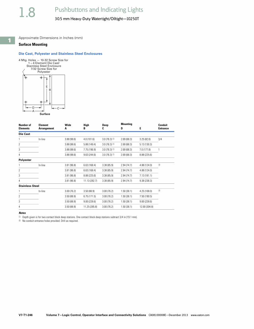
V7-T1-246 Volume 7—Logic Control, Operator Interface and Connectivity Solutions CA08100008E—December 2013 www.eaton.com
1
1
1
1
1
1
1
1
1
1
1
1
1
1
1
1
1
1
1
1
1
1
1
1
1
1
1
1
1
1
1.8 Pushbuttons and Indicating Lights
30.5 mm Heavy-Duty Watertight/Oiltight—10250T
Approximate Dimensions in Inches (mm)
Surface Mounting
Die Cast, Polyester and Stainless Steel Enclosures
Notes1 Depth given is for two contact block deep stations. One contact block deep stations subtract 3/4 in (19.1 mm).2 No conduit entrance holes provided. Drill as required.
ASurface
D C
BE
4 Mtg. Holes — 10-32 Screw Size for 1 – 4 Element Die Cast/
Stainless Steel Enclosure7/32 Screw Size for
Polyester
Number ofElements
ElementArrangement
WideA
HighB
DeepC
Mounting ConduitEntranceD E
Die Cast
1 In-line 3.88 (98.6) 4.0 (101.6) 3.0 (76.3) 1 2.69 (68.3) 3.25 (82.6) 3/4
2 3.88 (98.6) 5.88 (149.4) 3.0 (76.3) 1 2.69 (68.3) 5.13 (130.3)
3 3.88 (98.6) 7.75 (196.9) 3.0 (76.3) 1 2.69 (68.3) 7.0 (177.8) 1
4 3.88 (98.6) 9.63 (244.6) 3.0 (76.3) 1 2.69 (68.3) 8.88 (225.6)
Polyester
1 In-line 3.81 (96.8) 6.63 (168.4) 3.38 (85.9) 2.94 (74.7) 4.88 (124.0) 2
2 3.81 (96.8) 6.63 (168.4) 3.38 (85.9) 2.94 (74.7) 4.88 (124.0)
3 3.81 (96.8) 8.88 (225.6) 3.38 (85.9) 2.94 (74.7) 7.13 (181.1)
4 3.81 (96.8) 11.13 (282.7) 3.38 (85.9) 2.94 (74.7) 9.38 (238.3)
Stainless Steel
1 In-line 3.00 (76.2) 3.50 (88.9) 3.00 (76.2) 1.50 (38.1) 4.25 (108.0) 2
2 3.50 (88.9) 6.75 (171.5) 3.00 (76.2) 1.50 (38.1) 7.50 (190.5)
3 3.50 (88.9) 9.00 (228.6) 3.00 (76.2) 1.50 (38.1) 9.00 (228.6)
4 3.50 (88.9) 11.25 (285.8) 3.00 (76.2) 1.50 (38.1) 12.00 (304.8)
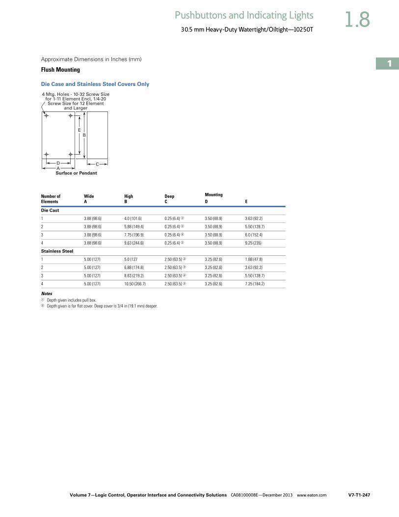
Volume 7—Logic Control, Operator Interface and Connectivity Solutions CA08100008E—December 2013 www.eaton.com V7-T1-247
1
1
1
1
1
1
1
1
1
1
1
1
1
1
1
1
1
1
1
1
1
1
1
1
1
1
1
1
1
1
1.8Pushbuttons and Indicating Lights
30.5 mm Heavy-Duty Watertight/Oiltight—10250T
Approximate Dimensions in Inches (mm)
Flush Mounting
Die Case and Stainless Steel Covers Only
Notes1 Depth given includes pull box.2 Depth given is for flat cover. Deep cover is 3/4 in (19.1 mm) deeper.
ASurface or Pendant
D C
BE
4 Mtg. Holes - 10-32 Screw Sizefor 1-11 Element Encl, 1/4-20Screw Size for 12 Element
and Larger
Number ofElements
WideA
HighB
DeepC
MountingD E
Die Cast
1 3.88 (98.6) 4.0 (101.6) 0.25 (6.4) 2 3.50 (88.9) 3.63 (92.2)
2 3.88 (98.6) 5.88 (149.4) 0.25 (6.4) 2 3.50 (88.9) 5.50 (139.7)
3 3.88 (98.6) 7.75 (196.9) 0.25 (6.4) 2 3.50 (88.9) 6.0 (152.4)
4 3.88 (98.6) 9.63 (244.6) 0.25 (6.4) 2 3.50 (88.9) 9.25 (235)
Stainless Steel
1 5.00 (127) 5.0 (127 2.50 (63.5) 2 3.25 (82.6) 1.88 (47.8)
2 5.00 (127) 6.88 (174.8) 2.50 (63.5) 2 3.25 (82.6) 3.63 (92.2)
3 5.00 (127) 8.63 (219.2) 2.50 (63.5) 2 3.25 (82.6) 5.50 (139.7)
4 5.00 (127) 10.50 (266.7) 2.50 (63.5) 2 3.25 (82.6) 7.25 (184.2)

V7-T1-248 Volume 7—Logic Control, Operator Interface and Connectivity Solutions CA08100008E—December 2013 www.eaton.com
1
1
1
1
1
1
1
1
1
1
1
1
1
1
1
1
1
1
1
1
1
1
1
1
1
1
1
1
1
1
1.8 Pushbuttons and Indicating Lights
30.5 mm Heavy-Duty Watertight/Oiltight—10250T
Approximate Dimensions in Inches (mm)
Flush and Long Pushbutton Half Shroud
Mushroom and Jumbo Head Pushbutton
Pushbutton with Cylinder Lock
Illuminated Pushbutton
Push-Pull Switch
Flush Pushbutton Operator with Padlock Attachment
Mushroom Head Pushbutton Operator with Padlock Attachment
Indicating Light—Transformer Type
1.81(46)
1.09(27.7)
1.06(26.9)
0.38(9.7)
1.38(35.1)
1.78(45.2)
LongButtonOnly
Half Shroud Is Same as Long Pushbutton with Lower Half of Guard Ring Cut Back
1.13(28.7)0.88 (22.4)
for EachAdditional
Contact Block
1.75(44.5)
1.63(41.4)
1.5(38.1)
2.5(63.5)
0.06 (1.5) to 0.25 (6.4)Panel Thickness
1.91(48.5)
1.13(28.7)
1.38(35.1)
1.09(27.7)
1.09(27.7)
0.69(17.5)
1.13(28.7)
1.38(35.1)
2.63(66.8)
1.65(41.9)
1.78(45.2)
0.25(6.4)
0.06 (1.5) to 0.25 (6.4)Panel Thickness
0.88(22.4)
0.88(22.4)
1.13(28.7)
2.03(51.6)
2.0(50.8)
1.09(27.7)
1.13(28.7)
1.78(45.2)
1.5(38.1)
1.63(41.4)
2.5(63.5)
2.0(50.8)
1.75(44.5)
1.8(45.7)
A
1.78(45.2)
1.1(27.9)
1.38(35.1)

Volume 7—Logic Control, Operator Interface and Connectivity Solutions CA08100008E—December 2013 www.eaton.com V7-T1-249
1
1
1
1
1
1
1
1
1
1
1
1
1
1
1
1
1
1
1
1
1
1
1
1
1
1
1
1
1
1
1.8Pushbuttons and Indicating Lights
30.5 mm Heavy-Duty Watertight/Oiltight—10250T
Approximate Dimensions in Inches (mm)
PresTest Indicating Light—Transformer Type
Jumbo Mushroom Head Pushbutton Operator with Padlock Attachment
Indicating Light—Resistor and Neon Type
PresTest Indicating Light—Resistor Type
Master Test Indicating Light
Potentiometer Shaft
Lens A
Plastic 1.38 (35.1)
Glass 1.56 (39.6)
2.19(55.6)
1.94(49.3)
1.56(39.6)
1.38(35.1)
1.78(45.2)
2.5(63.5)
2.31(58.7)
2.38(60.5)
1.75(44.5)
1.81(46)
A1.1
(27.9)
1.78(45.2)
1.38(35.1)
Description B C
Relay type 4.38 (111.2) 4.28 (108.7)
Solid-state type 2.94 (74.7) 2.88 (73.2)
OperatorCatalog Number A B
10250T330 0.38 (9.7) dia. x0.38 (9.7) long
0.25 (6.4) dia. x0.63 (16) long
1.88(47.8)
1.88(47.8)
1.56(39.6)
1.78(45.2)
1.38(35.1)
1.63(41.4)
BSpade Terminal
AScrew Terminal
1.78(45.2)
1.38(35.1)
Plastic 1.38 (35.1)Glass 1.59 (40.4)
Shaft Dimensions of PotentiometerThat C-H Operator Will Accept
A
BShaft
ThreadedBushing

V7-T1-250 Volume 7—Logic Control, Operator Interface and Connectivity Solutions CA08100008E—December 2013 www.eaton.com
1
1
1
1
1
1
1
1
1
1
1
1
1
1
1
1
1
1
1
1
1
1
1
1
1
1
1
1
1
1
1.8 Pushbuttons and Indicating Lights
30.5 mm Heavy-Duty Watertight/Oiltight—10250T
Approximate Dimensions in Inches (mm)
Coin Operated Selector Switch
Key Operated Selector Switch
Illuminated Selector Switch
Roto-Push
Wobble Stick Catalog No. 10250TA5
Lever Operator—For Use with Two Vertically Mounted Flush Pushbuttons Catalog No. 10250TA14
Flexible Boot—For Protecting Flush or Long Pushbutton Catalog No. 10250TA3 Typical
Transparent Flexible Boot—For Illuminated Pushbutton Catalog No. 10250TA25
Operator Dim. A
Knob 1.38 (35.1)
Lever 1.50 (38.1)
Coin slot 1.38 (35.1)
A
Lever
Knob
Coin Slot
1.38(35.1)
1.13(28.7)
1.75(44.5)
1.38(35.1)
1.13(28.7)
1.09(27.7)
1.96(49.8)
1.38(35.1)
1.13(28.7)
1.53(38.9)
0.38 (9.7)Long
ButtonOnly
1.38(35.1)
1.44(36.6)
1.22(31)
2.44(62)
21°
21°
1.88(47.8)3.75
(95.3)
2.19(55.6)
3.59(91.2)
Cam
1.59(40.4)
1.47(37.3)
1.33(33.8)
1.59(40.4)
1.88(47.8)

Volume 7—Logic Control, Operator Interface and Connectivity Solutions CA08100008E—December 2013 www.eaton.com V7-T1-251
1
1
1
1
1
1
1
1
1
1
1
1
1
1
1
1
1
1
1
1
1
1
1
1
1
1
1
1
1
1
1.8Pushbuttons and Indicating Lights
30.5 mm Heavy-Duty Watertight/Oiltight—10250T
Approximate Dimensions in Inches (mm)
Padlock Attachment—For Knob Selector Switch Catalog No. 10250TA11
Padlock Attachment—For Flush Pushbutton Catalog No. 10250TA2
Padlock Attachment—For Extended Pushbutton Catalog No. 10250TA26
Maintained Pushbutton Catalog No. 10250TA66 Typical
Maintained Contact Attachment Catalog No. 10250TA17 Typical
Padlock Cover Guard for Flush Pushbutton Catalog No. 10250TA36
Padlock Attachment for Maintained Push-Pull Operator Catalog No. 10250TA64
Protecting Shroud for Jumbo Mushroom Head Button Catalog No. 10250TA56
1.63(41.4)
0.44(11.2)
0.75(19.1) 0.84
(21.3)
0.94(23.9)
1.63(41.4)
0.25(6.4)
2.06(52.3)
0.38(9.7)
0.84(21.3)
1.5(38.1)
1.06(26.9)
0.89(22.6)
Adjustable
0.88(22.4)
for EachAdditional
ContactBlock
1.07(27.2)
1.62 (41.1)Min.
2.5 (63.5)Max.
0.97(24.6)
0.91(23.1)
1.63 (41.4)Min.
2.31 (58.7)Max.
1.13(28.7)
0.38(9.7)
1.16(29.5)
1.0(25.4)
1.91(48.5)
2.19(55.6)
0.75(19.1)
0.91(23.1)
2.19(55.6)
1.47(37.3)
1.25(31.8)
0.38(9.7)
0.94(23.9)
1.65(41.9)
3.25(82.6)

V7-T1-252 Volume 7—Logic Control, Operator Interface and Connectivity Solutions CA08100008E—December 2013 www.eaton.com
1
1
1
1
1
1
1
1
1
1
1
1
1
1
1
1
1
1
1
1
1
1
1
1
1
1
1
1
1
1
1.8 Pushbuttons and Indicating Lights
30.5 mm Heavy-Duty Watertight/Oiltight—10250T
Approximate Dimensions in Inches (mm)
Protecting Shroud for Mushroom Head Button Catalog No. 10250TA6
Protecting Shroud for Illuminated Pushbutton Catalog No. 10250TA15
Padlock Hasp or Flip-Up Guard Catalog No. 10250TA38
Extended Retaining Nut Catalog No. 10250TA12
Lever for Roto-Push Operator Catalog No. 10250TA13
1.53(38.9)
1.69(42.9)
1.75(44.5)
1.50(38.1)
0.84(21.3)
1.50(38.1)
1.75(44.5)
1.38(35.1)
1.31(33.3)
1.25(31.8)
0.44(11.2)
1.81(46)
Panel Drilling and Minimum Spacing
NotesLocating nib hole or notch is 1.36–1.4 in (34.5–35.6 mm) #29 drill.1 If jumbo plates are to be placed one above the other vertically, add 0.13 (3.3) to minimum
dimensions listed.
LegendPlate
AMin.
BMin.
1 or 2 Circuit Contact Blocks
Small or none 1.63 (41.4) 2.25 (57.2)
Standard 1.75 (44.5) 2.25 (57.2)
Jumbo 1 2.25 (57.2) 2.25 (57.2)
Extra large 2.50 (63.5) 2.60 (66)
4 Circuit Contact Block 10250T44
Small or none 1.88 (47.8) 2.25 (57.2)
Standard 1.88 (47.8) 2.25 (57.2)
Jumbo 1 2.25 (57.2) 2.25 (57.2)
Extra large 2.50 (63.5) 2.60 (66)
BMin.
AMin.
0.6(15.2)
AMin.
1.22(31)
BMin.
Horizontal Rows Vertical Rows
Terminals on Top
Terminals atSide

Volume 7—Logic Control, Operator Interface and Connectivity Solutions CA08100008E—December 2013 www.eaton.com V7-T1-253
1
1
1
1
1
1
1
1
1
1
1
1
1
1
1
1
1
1
1
1
1
1
1
1
1
1
1
1
1
1
1.8Pushbuttons and Indicating Lights
30.5 mm Heavy-Duty Watertight/Oiltight—10250T
Approximate Dimensions in Inches (mm)
Multiple Button Guard
Master Test Module, Flasher Module and Legend Plate
NotesLocating nib hole or notch is 1.36–1.4 in (34.5–35.6 mm) #29 drill.1 For plastic legend plate, Dimension B is 1.12 (28.4).
Chain Hook Bracket
Number ofElements A
2 4.0 (101.6)
3 5.88 (149.4)
4 7.88 (200.2)
7 13.38 (339.9)
LegendPlate A B
1/2 Round Legend Plates
Small 1.56 (39.6) 0.91 (23.1)
Standard 1.59 (40.4) 1.07 (27.2)
Jumbo 2.06 (52.3) 1.53 (38.9)
Square Legend Plates
Small 1.59 (40.4) sq. 0.90 (22.9)
Standard 1.75 (44.5) sq. 1.06 (26.9) 1
Jumbo 2.19 (55.6) sq. 1.50 (38.1)
Extra large 2.44 (62.0) sq. 1.63 (41.4)
2.16(54.9)
1.31(33.3)
1.88(47.8)
0.75(19.1)
A
1.63(41.4)
1.14(29)
6 Mounting Holes
1.78(45.2)
A
1.31(33.3)
Master Test Module,Flasher Module
Legend Plate
B
Enclosure Size(No. of Elements)
WideA
HighB
DeepC
MountingD E
2, 3 and 4 3.75 (95.3)
1.94 (49.3)
0.13 (3.3)
2.69 (68.3)
1.38 (35.1)
6 and 7 4.0 (101.6)
2.19 (55.6)
0.13 (3.3)
2.88 (73.2)
1.63 (41.4)
A C
D
B E
0.38 (9.7)Dia. Hole

V7-T1-254 Volume 7—Logic Control, Operator Interface and Connectivity Solutions CA08100008E—December 2013 www.eaton.com
1
1
1
1
1
1
1
1
1
1
1
1
1
1
1
1
1
1
1
1
1
1
1
1
1
1
1
1
1
1
1.9 Pushbuttons and Indicating Lights
30.5 mm Corrosion Resistant Watertight/Oiltight—E34
30.5 mm Corrosion Resistant Watertight/Oiltight—E34 ContentsDescription Page
30.5 mm Corrosion Resistant Watertight/Oiltight—E34Product Overview . . . . . . . . . . . . . . . . . . . . . . V7-T1-255
Product Identification . . . . . . . . . . . . . . . . . . . . V7-T1-256
Catalog Number Selection . . . . . . . . . . . . . . . . V7-T1-257
Ordering Complete Devices . . . . . . . . . . . . . . . V7-T1-259
Product Selection Non-Illuminated Momentary
Pushbutton Units . . . . . . . . . . . . . . . . . . . V7-T1-260
Plastic Lens Indicating Light Units . . . . . . . V7-T1-260
Pushbuttons . . . . . . . . . . . . . . . . . . . . . . . . V7-T1-261
Illuminated Pushbuttons and Indicating Lights . . . . . . . . . . . . . . . . . . . . V7-T1-262
Push-Pull Units . . . . . . . . . . . . . . . . . . . . . . V7-T1-264
Illuminated Push-Pull Units . . . . . . . . . . . . . V7-T1-265
Potentiometers . . . . . . . . . . . . . . . . . . . . . . V7-T1-267
Push-Pull Operators . . . . . . . . . . . . . . . . . . V7-T1-268
Selector Switch Units . . . . . . . . . . . . . . . . . V7-T1-272
Selector Switch Selection . . . . . . . . . . . . . . V7-T1-273
Selector Switch Operators . . . . . . . . . . . . . V7-T1-276
Key Operators . . . . . . . . . . . . . . . . . . . . . . . V7-T1-276
Illuminated Selector Switch Operators . . . . V7-T1-278
Accessories . . . . . . . . . . . . . . . . . . . . . . . . . . . V7-T1-279
Options . . . . . . . . . . . . . . . . . . . . . . . . . . . . . . V7-T1-281
Replacement Parts . . . . . . . . . . . . . . . . . . . . . . V7-T1-287
Technical Data and Specifications . . . . . . . . . . V7-T1-289
Dimensions . . . . . . . . . . . . . . . . . . . . . . . . . . . V7-T1-292
Product DescriptionEaton’s E34 Series 30.5 mm pushbutton line features the same rugged die cast construction of our 10250T line with an additional two-layer 100% solid thermosetting cathodic epoxy coating. This coating provides a flat black smooth, consistent, corrosion resistant surface that has passed a demanding 600 hour salt spray test. (The industry standard for this 4X test requires only 200 hours.)
Features● Epoxy-coated metal
operators● Corrosion resistant● Integral ground screw
terminal on operators● FDA approved for sanitary
chemical resistance requirements
Standards and Certifications● CE EN60947-5-1 and
60947-5-5● UL 508—File No. E131568● CSA C22.2 No. 14—File No.
LR68551● FDA 3-A Sanitary
Standards
Ingress Protection When mounted in similarly rated enclosure—
● Standard indicating lights● UL (NEMA) Type 1, 2, 3,
3R, 3S, 4, 4X, 12, 13 ● IEC IP65
● All other operators● UL (NEMA) Type 1, 2, 3,
3R, 4, 4X, 12, 13● IEC IP65

Volume 7—Logic Control, Operator Interface and Connectivity Solutions CA08100008E—December 2013 www.eaton.com V7-T1-255
1
1
1
1
1
1
1
1
1
1
1
1
1
1
1
1
1
1
1
1
1
1
1
1
1
1
1
1
1
1
1.9Pushbuttons and Indicating Lights
30.5 mm Corrosion Resistant Watertight/Oiltight—E34
Product OverviewUltraviolet LightE34 cathodic coating is not recommended for use in applications where exposure to ultraviolet light exists—use NEMA 4X 10250T operators.
Reliability NibsEaton’s contact blocks feature enclosed silver contacts with pointed “reliability nibs” for reliable performance from logic level up to 600V. To ensure reliable switching, nibs bite through oxide which can form on silver contacts, eliminating the need for expensive logic level blocks for most applications.
Reliability Nibs
Dry Circuit
Medium Duty
Heavy-Duty
Diaphragm Seal with Drainage Holes
Liquid DrainageEaton’s pushbutton operators offer front of panel drainage via holes in the operator bushing. Hidden from view by the mounting nut, these holes prevent buildup of liquid inside the operator, which can prevent operation in freezing environments. The holes also provide a route for escaping liquid in high pressure washdowns, effectively relieving pressure from the internal diaphragm seal, ensuring reliable sealing in applications even beyond NEMA 4.
Diaphragm Seal
Foam NeoprenePanel Sealing Gasket
Drainage Hole
Drainage Hole
FlexibleDiaphragm
StainlessSteel
OperatingSpring
Mounting Nut
ColorfastMoldedButton

V7-T1-256 Volume 7—Logic Control, Operator Interface and Connectivity Solutions CA08100008E—December 2013 www.eaton.com
1
1
1
1
1
1
1
1
1
1
1
1
1
1
1
1
1
1
1
1
1
1
1
1
1
1
1
1
1
1
1.9 Pushbuttons and Indicating Lights
30.5 mm Corrosion Resistant Watertight/Oiltight—E34
Product Identification
30.5 mm Corrosion Resistant Watertight/Oiltight—E34 Series
Octagonal Mounting Nut Self-Adjusts toPanel Thickness—Eliminates Spacer Washers
and Set Screws
Internal Sealing Diaphragmfor Excellent Sealing
Terminal Clamps ShippedOpen Ready to Wire
Three Styles of Legend Platesin Four Sizes Wide Variety of Operator
Types and Colors
Die Cast Construction with Thick, Tough Corrosion Resistant Coating Stackable Contact Blocks up
to 12 Circuits per Operator

Volume 7—Logic Control, Operator Interface and Connectivity Solutions CA08100008E—December 2013 www.eaton.com V7-T1-257
1
1
1
1
1
1
1
1
1
1
1
1
1
1
1
1
1
1
1
1
1
1
1
1
1
1
1
1
1
1
1.9Pushbuttons and Indicating Lights
30.5 mm Corrosion Resistant Watertight/Oiltight—E34
Catalog Number SelectionCatalog Number Selection is for illustrative purposes only and not to be used to create new catalog numbers.
Non-Illuminated Pushbuttons
Illuminated and Non-Illuminated Push-Pulls
Note1 Add X at end of catalog number to receive parts assembled from factory.
E34 PB 1 – 1 1
OperatorPB = FlushEB = ExtendedLB = 40 mm mushroomJB = 65 mm mushroom
EVB = 1/2 shroud vertical mountEHB = 1/2 shroud horizontal mount
CircuitBlank = Operator only
1 = 1NO-1NC2 = 2NO3 = 2NC
51 = 1NC53 = 1NO
Button Color1 = Black2 = Red3 = Green4 = Yellow
7 = Gray5 = White6 = Blue8 = Orange
E34 GDB 63 M2 – 1 1
CircuitBlank = Operator only
1 = 1NO-1NC2 = 2NO3 = 2NC
51 = 1NC53 = 1NOIncandescent
Light UnitLED
Light UnitBlank = Non-illuminated
89 = 24V/XFR63 = 120V/XFR64 = 208V/XFR65 = 240V/XFR82 = 277V/XFR66 = 380V/XFR67 = 480V/XFR68 = 600V/XFR69 = 6V/FV70 = 12V/FV79 = 24V/FV83 = 32V/FV80 = 120V/RES81 = 240V/RES
Blank = Non-illuminated89L = 24V/XFR63L = 120V/XFR64L = 208V/XFR65L = 240V/XFR82L = 277V/XFR66L = 380V/XFR67L = 480V/XFR68L = 600V/XFR97L = Full voltage
Non-Illuminated IlluminatedButton Incandescent LED Lens Type
C1 = Black 40 mmC2 = Red 40 mm
C2N8 = Red 40 mm—“E” STOPC3 = Green 40 mmC6 = Blue 40 mm— = Black 65 mmJ2 = Red 65 mm
J2N8 = Red 65 mm—“E” STOP— = Green 65 mm— = Yellow 65 mm
M2 =M2N8 =
M3 =M6 =M9 =M5 =M0 =
RD =ED =GD =LD =AD =
WD =— =
Red 40 mmRed 40 mm—“E” STOPGreen 40 mmBlue 40 mmAmber 40 mmWhite 40 mmClear 40 mm
LED VoltageBlank = Non-illuminatedBlank = Incandescent
06 = 6 Vac/Vdc12 = 12 Vac/Vdc24 = 24 Vac/Vdc48 = 48 Vac/Vdc60 = 60 Vac/Vdc2A = 120 Vac2D = 120 Vdc
OperatorGDB = Two-position maintainedGEB = Three-position mom push-mom pullGFB = Three-position mt push-mom pullGHB = Three-position mom push-mom pull

V7-T1-258 Volume 7—Logic Control, Operator Interface and Connectivity Solutions CA08100008E—December 2013 www.eaton.com
1
1
1
1
1
1
1
1
1
1
1
1
1
1
1
1
1
1
1
1
1
1
1
1
1
1
1
1
1
1
1.9 Pushbuttons and Indicating Lights
30.5 mm Corrosion Resistant Watertight/Oiltight—E34
Catalog Number Selection is for illustrative purposes only and not to be used to create new catalog numbers.
Illuminated Pushbuttons
Standard Indicating Lights, PresTest and Master Test
Note1 Add X at end of catalog number to receive parts assembled from factory.
CircuitBlank = Operator only
1 = 1NO-1NC2 = 2NO3 = 2NC
51 = 1NC53 = 1NO
Light Unit TypeXB = TransformerCB = Full voltageSB = Resistor
Incandescent Light Unit LED Light Unit024 = 24V/XFR120 = 120V/XFR240 = 240V/XFR277 = 277V/XFR380 = 380V/XFR480 = 480V/XFR600 = 600V/XFR
06 = 6V/FV12 = 12V/FV24 = 24V/FV32 = 32V/FV48 = 48V/FV
120 = 120V/RES240 = 240V/RES
024L = 24V/XFR120L = 120V/XFR240L = 240V/XFR277L = 277V/XFR380L = 380V/XFR480L = 480V/XFR600L = 600V/XFR397L = Full voltage
LED VoltageBlank = Incandescent
06 = 6 Vac/Vdc12 = 12 Vac/Vdc24 = 24 Vac/Vdc
48 = 48 Vac/Vdc60 = 60 Vac/Vdc2A = 120 Vac2D = 120 Vdc
Incandescent Lens Color LED Lens ColorV2 = RedV3 = GreenV4 = YellowV5 = WhiteV6 = BlueV9 = AmberV0 = Clear
RD = RedGD = GreenYD = Yellow
WD = WhiteLD = BlueAD = Amber
E34 XB 24 V2 – 1 1
LED VoltageBlank = Incandescent
06 = 6 Vac/Vdc12 = 12 Vac/Vdc24 = 24 Vac/Vdc48 = 48 Vac/Vdc60 = 60 Vac/Vdc2A = 120 Vac2D = 120 Vdc
Plastic Glass Lens Color Plastic Glass Lens ColorStandard/Master—Incandescent Standard/Master/PresTest—LED
H2 =H3 =H4 =H5 =H6 =H9 =H0 =
G2 =G3 =G4 =G5 =G6 =G9 =G0 =
RedGreenYellowWhiteBlueAmberClear
RP =GP =YP =
WP =LP =AP =
RG =GG =YG =
WG =LG =AG =
RedGreenYellowWhiteBlueAmber
PresTest—IncandescentV2 =V3 =V4 =V5 =V6 =V9 =V0 =
P2 =P3 =P4 =P5 =P6 =P9 =P0 =
RedGreenYellowWhiteBlueAmberClear
Light Unit TypeStandard—Incandescent Standard—LED
TB120 =TB240 =TB277 =TB380 =TB480 =TB600 =
FB06 =FB12 =FB24 =FB32 =FB48 =
RB120 =RB240 =NB120 =NB240 =
120V/XFR240V/XFR277V/XFR380V/XFR480V/XFR600V/XFR6V/FV12V/FV24V/FV32V/FV48V/FV120V/RES240V/RES120V/neon240V/neon
TB120L =TB240L =TB277L =TB380L =TB480L =TB600L =FB197L =
120V/XFR240V/XFR277V/XFR380V/XFR480V/XFR600V/XFRFull voltage
PresTest—LEDTPB120L =TPB240L =TPB380L =TPB480L =TPB600L =FPB297L =
120V/XFR240V/XFR380V/XFR480V/XFR600V/XFRFull voltage
PresTest—IncandescentTPB120 =TPB240 =TPB380 =TPB480 =TPB600 =
FPB06 =FPB12 =FPB24 =FPB32 =FPB48 =
RPB120 =RPB240 =
120V/XFR240V/XFR380V/XFR480V/XFR600V/XFR6V/FV12V/FV24V/FV32V/FV48V/FV120V/RES240V/RES
E34 FB06 H2 1

Volume 7—Logic Control, Operator Interface and Connectivity Solutions CA08100008E—December 2013 www.eaton.com V7-T1-259
1
1
1
1
1
1
1
1
1
1
1
1
1
1
1
1
1
1
1
1
1
1
1
1
1
1
1
1
1
1
1.9Pushbuttons and Indicating Lights
30.5 mm Corrosion Resistant Watertight/Oiltight—E34
Catalog Number Selection is for illustrative purposes only and not to be used to create new catalog numbers.
Ordering Complete DevicesComplete E34 pushbuttons, indicating lights and/or selector switch operators including contact block(s) and legend plate can be ordered using a single composite catalog number. The
individually packaged components will be shipped unassembled in a single overpack carton marked with the composite catalog number.
Ordering ExampleIlluminated Pushbutton Device—Catalog Number E34XB120V2-153SP90
For a complete Catalog Number breakdown, see Pages V7-T1-257 toV7-T1-258.
For Complete E34 Device Ordering
Operator Legend Plate E34;SP90
Insert Hyphen Before Contact Block(s)
LensE34V2 Contact Blocks
10250T1 and 10250T53
E34XB120 V2 – 153 SP90
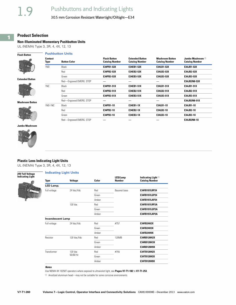
V7-T1-260 Volume 7—Logic Control, Operator Interface and Connectivity Solutions CA08100008E—December 2013 www.eaton.com
1
1
1
1
1
1
1
1
1
1
1
1
1
1
1
1
1
1
1
1
1
1
1
1
1
1
1
1
1
1
1.9 Pushbuttons and Indicating Lights
30.5 mm Corrosion Resistant Watertight/Oiltight—E34
Product SelectionNon-Illuminated Momentary Pushbutton UnitsUL (NEMA) Type 3, 3R, 4, 4X, 12, 13
Pushbutton Units
Plastic Lens Indicating Light Units UL (NEMA) Type 3, 3R, 4, 4X, 12, 13
Indicating Light Units
NotesUse NEMA 4X 10250T operators where exposed to ultraviolet light, see Pages V7-T1-182 to V7-T1-253.1 Anodized aluminum head—may not be suitable for some corrosive environments.
ContactType Button Color
Flush ButtonCatalog Number
Extended ButtonCatalog Number
Mushroom ButtonCatalog Number
Jumbo Mushroom 1Catalog Number
1NO Black E34PB1-53X E34EB1-53X E34LB1-53X E34JB1-53X
Red E34PB2-53X E34EB2-53X E34LB2-53X E34JB2-53X
Green E34PB3-53X E34EB3-53X E34LB3-53X E34JB3-53X
Red—Engraved EMERG. STOP — — — E34JB2N8-53X
1NC Black E34PB1-51X E34EB1-51X E34LB1-51X E34JB1-51X
Red E34PB2-51X E34EB2-51X E34LB2-51X E34JB2-51X
Green E34PB3-51X E34EB3-51X E34LB3-51X E34JB3-51X
Red—Engraved EMERG. STOP — — — E34JB2N8-51X
1NO-1NC Black E34PB1-1X E34EB1-1X E34LB1-1X E34JB1-1X
Red E34PB2-1X E34EB2-1X E34LB2-1X E34JB2-1X
Green E34PB3-1X E34EB3-1X E34LB3-1X E34JB3-1X
Red—Engraved EMERG. STOP — — — E34JB2N8-1X
Type Voltage ColorLED/LampNumber
Indicating Light 1Catalog Number
LED Lamp;
Full voltage 24 Vac/Vdc Red Bayonet base E34FB197LRP24
Green E34FB197LGP24
Amber E34FB197LAP24
120 Vac Red E34FB197LRP2A
Green E34FB197LGP2A
Amber E34FB197LAP2A
Incandescent Lamp
Full voltage 24 Vac/Vdc Red #757 E34FB24H2X
Green E34FB24H3X
Amber E34FB24H9X
Resistor 120 Vac/Vdc Red 120MB E34RB120H2X
Green E34RB120H3X
Amber E34RB120H9X
Transformer 120 Vac50/60 Hz
Red #755 E34TB120H2X
Green E34TB120H3X
Amber E34TB120H9X
Flush Button
Extended Button
Mushroom Button
Jumbo Mushroom
24V Full Voltage Indicating Light

Volume 7—Logic Control, Operator Interface and Connectivity Solutions CA08100008E—December 2013 www.eaton.com V7-T1-261
1
1
1
1
1
1
1
1
1
1
1
1
1
1
1
1
1
1
1
1
1
1
1
1
1
1
1
1
1
1
1.9Pushbuttons and Indicating Lights
30.5 mm Corrosion Resistant Watertight/Oiltight—E34
PushbuttonsUL (NEMA) Type 3, 3R, 4, 4X, 12, 13
Momentary Pushbutton Operators, Non-Illuminated
NotesUse NEMA 4X 10250T operators where exposed to ultraviolet light, see Pages V7-T1-182 to V7-T1-253.1 Anodized aluminum head—may not be suitable for some corrosive environments.
Button Color Catalog Number
Flush button Black E34PB1
Red E34PB2
Green E34PB3
Yellow E34PB4
White E34PB5
Blue E34PB6
Gray E34PB7
Orange E34PB8
Extended button Black E34EB1
Red E34EB2
Green E34EB3
Yellow E34EB4
White E34EB5
Blue E34EB6
Gray E34EB7
Orange E34EB8
Half shrouded button Vertical Horizontal
Black E34EVB1 E34EHB1
Red E34EVB2 E34EHB2
Green E34EVB3 E34EHB3
Yellow E34EVB4 E34EHB4
White E34EVB5 E34EHB5
Blue E34EVB6 E34EHB6
Gray E34EVB7 E34EHB7
Orange E34EVB8 E34EHB8
Mushroom button Black E34LB1
Red E34LB2
Green E34LB3
Yellow E34LB4
Blue E34LB6
Anodized aluminum jumbo mushroom button 1
Black E34JB1
Red E34JB2
Red (Engraved EMERG. STOP) E34JB2N8
Green E34JB3
Yellow E34JB4
E34PB_
E34EB_
E34EHB_
E34LB_
E34JB_

V7-T1-262 Volume 7—Logic Control, Operator Interface and Connectivity Solutions CA08100008E—December 2013 www.eaton.com
1
1
1
1
1
1
1
1
1
1
1
1
1
1
1
1
1
1
1
1
1
1
1
1
1
1
1
1
1
1
1.9 Pushbuttons and Indicating Lights
30.5 mm Corrosion Resistant Watertight/Oiltight—E34
Illuminated Pushbuttons and Indicating Lights
Operators without Lens
NotesUse NEMA 4X 10250T operators where exposed to ultraviolet light, see Pages V7-T1-182 to V7-T1-253.1 These units do not include lamps. Order LED separately to match lens color, see Page V7-T1-239 for LED Selection and Pages V7-T1-257 to V7-T1-258 for Catalog
Numbering Selection.2 Resistor units are not available for use with LEDs, choose either transformer or full voltage LED style.
Type Voltage Lamp Number
Illuminated PushbuttonCatalog Number
IndicatingLightCatalog Number
PresTestCatalog Number
LED Lamp (LEDs not included) 1
Full voltage — Bayonetbase
E34CB497L E34FB197L E34FPB297L
Transformer AC only 24 E34XB024L — —
120 E34XB120L E34TB120L E34TPB120L
240 E34XB240L E34TB240L E34TPB240L
277 E34XB277L E34TB277L —
380 E34XB380L E34TB380L E34TPB380L
480 E34XB480L E34TB480L E34TPB480L
600 E34XB600L E34TB600L E34TPB600L
Incandescent Lamp
Full voltage AC/DC 6 #755 E34CB06 E34FB06 E34FPB06
12 #756 E34CB12 E34FB12 E34FPB12
24 #757 E34CB24 E34FB24 E34FPB24
32 #1828 E34CB32 E34FB32 E34FPB32
48 #1835 E34CB48 E34FB48 E34FPB48
Resistor AC/DC 2 120 120MB E34SB120 E34RB120 E34RPB120
240 E34SB240 E34RB240 E34RPB240
Transformer AC only 24 #755 E34XB024 — —
120 E34XB120 E34TB120 E34TPB120
240 E34XB240 E34TB240 E34TPB240
277 E34XB277 E34TB277 —
380 E34XB380 E34TB380 E34TPB380
480 E34XB480 E34TB480 E34TPB480
600 E34XB600 E34TB600 E34TPB600
Neon AC/DC 120 NE51H-R-22 — E34NB120 —
240 NE51H-4-68 — E34NB240 —
Illuminated Pushbutton
Indicating Light
PresTest

Volume 7—Logic Control, Operator Interface and Connectivity Solutions CA08100008E—December 2013 www.eaton.com V7-T1-263
1
1
1
1
1
1
1
1
1
1
1
1
1
1
1
1
1
1
1
1
1
1
1
1
1
1
1
1
1
1
1.9Pushbuttons and Indicating Lights
30.5 mm Corrosion Resistant Watertight/Oiltight—E34
Indicating Light Lens
Illuminated Pushbutton Lens
PresTest Lens
Note1 Glass lens has black anodized aluminum bezel.
ColorPlasticCatalog Number
Glass 1Catalog Number
Red E34H2 E34G2
Green E34H3 E34G3
Yellow E34H4 E34G4
White E34H5 E34G5
Blue E34H6 E34G6
Ambler E34H9 E34G9
Clear E34H0 E34G0
Color Catalog Number
Red E34V2
Green E34V3
Yellow E34V4
White E34V5
Blue E34V6
Ambler E34V9
Clear E34V0
ColorPlasticCatalog Number
Glass 1Catalog Number
Red E34V2 E34P2
Green E34V3 E34P3
Yellow E34V4 E34P4
White E34V5 E34P5
Blue E34V6 E34P6
Ambler E34V9 E34P9
Clear E34V0 E34P0
Plastic
Glass
E34V_
Plastic
Glass

V7-T1-264 Volume 7—Logic Control, Operator Interface and Connectivity Solutions CA08100008E—December 2013 www.eaton.com
1
1
1
1
1
1
1
1
1
1
1
1
1
1
1
1
1
1
1
1
1
1
1
1
1
1
1
1
1
1
1.9 Pushbuttons and Indicating Lights
30.5 mm Corrosion Resistant Watertight/Oiltight—E34
Push-Pull UnitsUL (NEMA) Type 3, 3R, 4, 4X, 12, 13
● Two- and three-position● Non-illuminated
Two-Position Push-Pull Units, Non-Illuminated
Three-Position Push-Pull Units, Non-Illuminated
Button and Color Selection
NotesUse NEMA 4X 10250T operators where exposed to ultraviolet light, see Pages V7-T1-182 to V7-T1-253.1 X = closed circuit, O = open circuit.2 To order different type or color buttons, substitute the underlined characters with appropriate suffix code
from the table. Example: E34GDBC6-1X.3 Anodized aluminum may not be suitable for use on some corrosive applications.
Operator Position 1
Button Type/Color 2Contact Type Catalog Number
Pull Push Mounting Location
A B
Maintained Push, Maintained Pull
OX
XO
40 mm/red 1NO E34GDBC2-1X
40 mm engravedEMERG. STOP/red
1NC E34GDBC2N8-1X
65 mm aluminum engravedEMERG. STOP/red
E34GDBJ2N8-1X
Operator Position 1
Button Type/Color 2Contact Type Catalog Number
Pull Intermediate Push Mounting Location
A B
Maintained Push, Momentary Pull
XX
OX
OO
40 mm/black 1NC E34GFBC1-3X
40 mm/red 1NC E34GFBC2-3X
40 mm engravedEMERG. STOP/red
E34GFBC2N8-3X
Momentary Push, Momentary Pull
XX
OX
OO
40 mm/black 1NC E34GEBC1-3X
40 mm/red 1NC E34GEBC2-3X
OX
OO
XO
40 mm/black 1NO E34GHBC1-1X
40 mm/red 1NC E34GHBC2-1X
Color Suffix Code Catalog Number
Standard—40 mm
Black C1 E34C1
Red C2 E34C2
Red (EMERG. STOP) C2N8 E34C2N8
Green C3 E34C3
Blue C6 E34C6
Jumbo Mushroom Head 3
(Anodized) Aluminum—65 mm
Red J2 E34J2
Red (EMERG. STOP) J2N8 E34J2N8
Two-Position Push-Pull Unit
Three-Position Push-Pull Unit
Standard
Jumbo Mushroom Head

Volume 7—Logic Control, Operator Interface and Connectivity Solutions CA08100008E—December 2013 www.eaton.com V7-T1-265
1
1
1
1
1
1
1
1
1
1
1
1
1
1
1
1
1
1
1
1
1
1
1
1
1
1
1
1
1
1
1.9Pushbuttons and Indicating Lights
30.5 mm Corrosion Resistant Watertight/Oiltight—E34
Illuminated Push-Pull UnitsUL (NEMA) Type 3, 3R, 4, 4X, 12, 13
● Two-position maintained● Illuminated
Two-Position Illuminated Maintained Push, Maintained Pull
Lens and Color Selection
NotesUse NEMA 4X 10250T operators where exposed to ultraviolet light, see Pages V7-T1-182 to V7-T1-253.1 X = closed circuit, O = open circuit.2 To order different type or color lens, substitute the underlined characters with appropriate suffix code from Lens and Color Selection table above.
Example: E34GDB79M3 -1X. For LEDs with different voltages see ordering example on Page V7-T1-271.
Operator Position 1
Lamp Type VoltageContactType
LED/LampNumber
Red Standard Push-Pull Catalog Number 2
Maintained—Pull
Maintained—Intermediate Mounting Location
A B
OX
XO
LED Full voltage 24 Vac/Vdc 1NO Bayonetbase
E34GDB97LRD24-1X
120 Vac/Vdc 1NC E34GDB97LRD2A-1X
Transformer 24 Vac E34GDB89LRD06-1X
120 Vac E34GDB63LRD06-1X
OX
XO
Incan-descent
Full voltage 24 Vac/Vdc 1NO #757 E34GDB79M2-1X
Resistor 120 Vac/Vdc 1NC 120MB E34GDB80M2-1X
Transformer 24 Vac #755 E34GDB89M2-1X
120 Vac E34GDB63M2-1X
ColorIncandescentSuffix Code
LEDSuffix Code Catalog Number
Standard
Red M2 RD E34M2
Red (EMER. STOP) M2N8 ED E34M2N8
Green M3 GD E34M3
Blue M6 LD E34M6
Amber M9 AD E34M9
White M5 WD E34M5
Clear M0 CD E34M0
Illuminated Push-Pull Unit
Standard

V7-T1-266 Volume 7—Logic Control, Operator Interface and Connectivity Solutions CA08100008E—December 2013 www.eaton.com
1
1
1
1
1
1
1
1
1
1
1
1
1
1
1
1
1
1
1
1
1
1
1
1
1
1
1
1
1
1
1.9 Pushbuttons and Indicating Lights
30.5 mm Corrosion Resistant Watertight/Oiltight—E34
UL (NEMA) Type 3, 3R, 4, 4X, 12, 13
● Three-position maintained● Illuminated
Three-Position Illuminated Momentary Push, Momentary Pull
NotesUse NEMA 4X 10250T operators where exposed to ultraviolet light, see Pages V7-T1-182 to V7-T1-253.1 X = closed circuit, O = open circuit.2 To order different type or color lens, substitute the underlined characters with appropriate suffix code from Lens and Color Selection table on the
bottom of Page V7-T1-265. Example: E34GEB79M3-3X. For LEDs with different voltages see ordering example on Page V7-T1-271.
Operator Position 1
Lamp Type VoltageContact Type
LED/LampNumber
Red Standard Push-Pull Catalog Number 2
Momentary—Pull
Maintained—Intermediate
Momentary—Push Mounting Location
A B
OX
OO
XO
LED Full voltage
24 Vac/Vdc 1NO Bayonetbase
E34GHB97LRD24-1X
120 Vac 1NC E34GHB97LRD2A-1X
Trans-former
24 Vac E34GHB89LRD06-1X
120 Vac E34GHB63LRD06-1X
XX
OX
OO
Full voltage
24 Vac/Vdc 1NC Bayonetbase
E34GEB97LRD24-3X
120 Vac 1NC E34GEB97LRD2A-3X
Trans-former
24 Vac E34GEB89LRD06-3X
120 Vac E34GEB63LRD06-3X
OX
OO
XO
Incan-descent
Full voltage
24 Vac/Vdc 1NO #757 E34GHB79M2-1X
Resistor 120 Vac 1NC 120MB E34GHB80M2-1X
Trans-former
24 Vac #755 E34GHB89M2-1X
120 Vac E34GHB63M2-1X
XX
OX
OO
Full voltage
24 Vac/Vdc 1NC #757 E34GEB79M2-3X
Resistor 120 Vac 1NC 120MB E34GEB80M2-3X
Trans-former
24 Vac #755 E34GEB89M2-3X
120 Vac E34GEB63M2-3X
Illuminated Push-Pull Unit
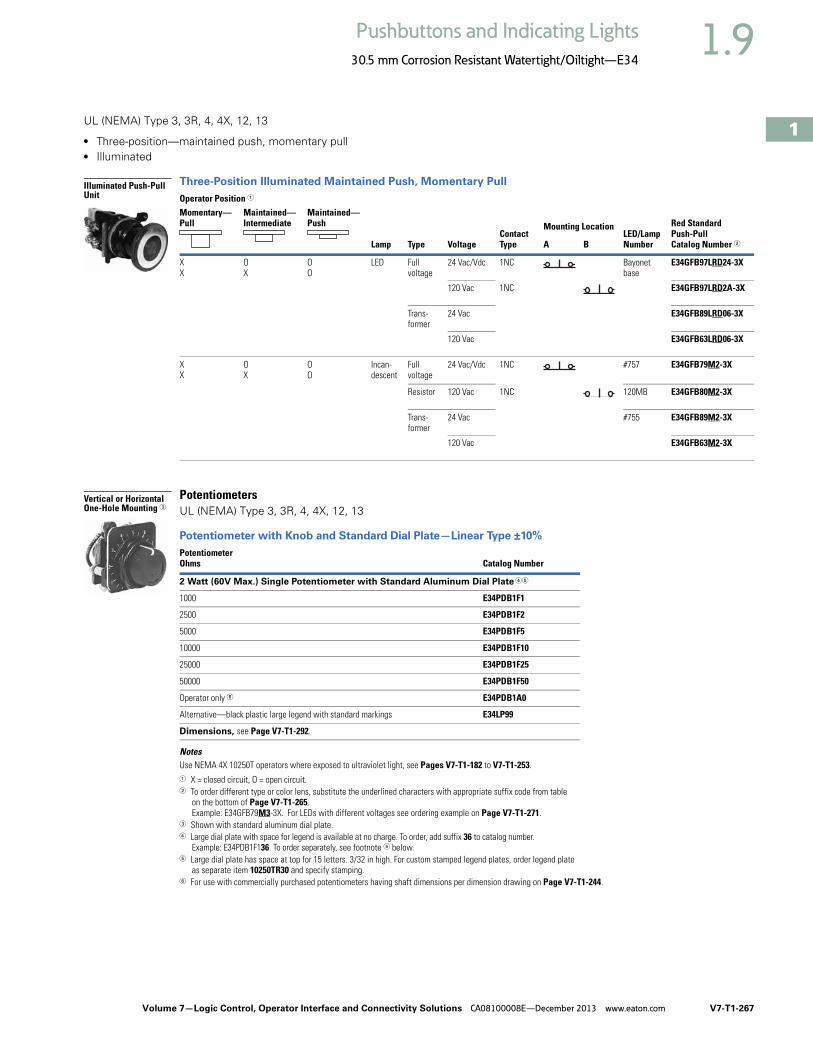
Volume 7—Logic Control, Operator Interface and Connectivity Solutions CA08100008E—December 2013 www.eaton.com V7-T1-267
1
1
1
1
1
1
1
1
1
1
1
1
1
1
1
1
1
1
1
1
1
1
1
1
1
1
1
1
1
1
1.9Pushbuttons and Indicating Lights
30.5 mm Corrosion Resistant Watertight/Oiltight—E34
UL (NEMA) Type 3, 3R, 4, 4X, 12, 13
● Three-position—maintained push, momentary pull● Illuminated
Three-Position Illuminated Maintained Push, Momentary Pull
PotentiometersUL (NEMA) Type 3, 3R, 4, 4X, 12, 13
Potentiometer with Knob and Standard Dial Plate—Linear Type ±10%
NotesUse NEMA 4X 10250T operators where exposed to ultraviolet light, see Pages V7-T1-182 to V7-T1-253.1 X = closed circuit, O = open circuit.2 To order different type or color lens, substitute the underlined characters with appropriate suffix code from table
on the bottom of Page V7-T1-265. Example: E34GFB79M3-3X. For LEDs with different voltages see ordering example on Page V7-T1-271.
3 Shown with standard aluminum dial plate.4 Large dial plate with space for legend is available at no charge. To order, add suffix 36 to catalog number.
Example: E34PDB1F136. To order separately, see footnote 5 below.5 Large dial plate has space at top for 15 letters. 3/32 in high. For custom stamped legend plates, order legend plate
as separate item 10250TR30 and specify stamping.6 For use with commercially purchased potentiometers having shaft dimensions per dimension drawing on Page V7-T1-244.
Operator Position 1
Lamp Type VoltageContact Type
LED/LampNumber
Red Standard Push-Pull Catalog Number 2
Momentary—Pull
Maintained—Intermediate
Maintained—Push Mounting Location
A B
XX
OX
OO
LED Full voltage
24 Vac/Vdc 1NC Bayonetbase
E34GFB97LRD24-3X
120 Vac 1NC E34GFB97LRD2A-3X
Trans-former
24 Vac E34GFB89LRD06-3X
120 Vac E34GFB63LRD06-3X
XX
OX
OO
Incan-descent
Full voltage
24 Vac/Vdc 1NC #757 E34GFB79M2-3X
Resistor 120 Vac 1NC 120MB E34GFB80M2-3X
Trans-former
24 Vac #755 E34GFB89M2-3X
120 Vac E34GFB63M2-3X
PotentiometerOhms Catalog Number
2 Watt (60V Max.) Single Potentiometer with Standard Aluminum Dial Plate 45
1000 E34PDB1F1
2500 E34PDB1F2
5000 E34PDB1F5
10000 E34PDB1F10
25000 E34PDB1F25
50000 E34PDB1F50
Operator only 6 E34PDB1A0
Alternative—black plastic large legend with standard markings E34LP99
Dimensions, see Page V7-T1-292.
Illuminated Push-Pull Unit
Vertical or Horizontal One-Hole Mounting 3

V7-T1-268 Volume 7—Logic Control, Operator Interface and Connectivity Solutions CA08100008E—December 2013 www.eaton.com
1
1
1
1
1
1
1
1
1
1
1
1
1
1
1
1
1
1
1
1
1
1
1
1
1
1
1
1
1
1
1.9 Pushbuttons and Indicating Lights
30.5 mm Corrosion Resistant Watertight/Oiltight—E34
Push-Pull OperatorsAn illuminated push-pull pushbutton unit, arranged for one-hole mounting, can replace two pushbuttons and a pilot light or the non-illuminated form can replace two pushbuttons. These units are available in three basic types:
● Maintained—(Two-position). Maintains in the pulled or pushed position until manually actuated to the opposite mode.
● Momentary—(Three-position). Spring returns to an intermediate position when pulled or pushed and released.
● Momentary Pull, Maintained Push—(Three-position). Spring returns to intermediate position when pulled. Maintains in pushed position until manually returned to intermediate (ready to reset) position. Maintained stop holds circuit open and will prevent other series connected operators from starting the system.
The operators, buttons, contact blocks, etc., are offered as building block components that can be intermixed to satisfy many requirements. This minimizes the need for a varied and costly inventory.
Application GuideTo assist in the selection of contact blocks, the sketch below shows pictorially by symbols A and B locations of contact circuits after assembly of contact blocks and adapter to the operator. The table below shows the effect of the push and pull operations on either NO or NC contacts. (X = contact closed, O = contact open).
Contact Circuit Locations
Push-Pull Operator Components
NotesUse NEMA 4X 10250T operators where exposed to ultraviolet light, see Pages V7-T1-182 to V7-T1-253.
See Typical Applications on Page V7-T1-203.1 Shown without button on lens.2 Maximum of two blocks, four circuits. Special function contact blocks shown on Page V7-T1-286 CANNOT be used with
three-position push-pull operators E34GEB, E34GFB or E34GHB.
Locating Nib
A
B
Type of Operator
Operator Position and Circuit Arrangement
Contact Block 2 Catalog Number
Out—Pull Intermediate In—Push
Contact Block Mounting LocationA B A B A B
Two-Position Operator without Lens
Maintained push-pull OX or O
XNo intermediateposition
XO or X
O1NO1NC
E34GDB
OX
OX
XO
XO
2NO2NC
Three-Position Operator without Lens
Momentary push-pull OX or O
XOO or O
XXO or O
O1NO1NC
E34GEB 2
OX
OX
OO
OX
XO
OO
2NO2NC
Maintained push-momentary pull OX or O
XOO or O
XXO or O
O1NO1NC
E34GFB 2
OX
OX
OO
OX
XO
OO
2NO2NC
Momentary push-pull OX or O
XOO or O
OXO or X
O1NO1NC
E34GHB 2
OX
OX
OO
OO
XO
XO
2NO2NC
Two-Position Maint. Push-Pull 1

Volume 7—Logic Control, Operator Interface and Connectivity Solutions CA08100008E—December 2013 www.eaton.com V7-T1-269
1
1
1
1
1
1
1
1
1
1
1
1
1
1
1
1
1
1
1
1
1
1
1
1
1
1
1
1
1
1
1.9Pushbuttons and Indicating Lights
30.5 mm Corrosion Resistant Watertight/Oiltight—E34
Push-Pull Light Units, Lenses and ButtonsOrdering Example with One Composite Number
Non-illuminated:E34GDB + E34C2 + 10250T1 = E34GDBC2-1X
Incandescent:E34GDB + 10250T79 + E34M2 + 10250T1 = E34GDB79M2-1X
LED:E34GDB + 10250T97L + E34M2 + Voltage Code + 10250T1 = E34GDB97LRD24-1X
06—6 Vac/Vdc12—12 Vac/Vdc24—24 Vac/Vdc48—48 Vac/Vdc
60—60 Vac/Vdc2A—120 Vac2D—120 Vdc
Light Units for Illuminated Push-Pull Devices
NotesUse NEMA 4X 10250T operators where exposed to ultraviolet light, see Pages V7-T1-182 to V7-T1-253.1 These units do not include lamps. Order LED separately to match lens color from chart on Page V7-T1-271.
Light Unit Type Type Voltage
LED/LampNumber Catalog Number
LED(LEDs not included) 1
Full voltage — Bayonetbase
10250T97L
Transformer AC only50/60 Hz
24 10250T89L
120 10250T63L
208 10250T64L
240 10250T65L
277 10250T82L
380 10250T66L
480 10250T67L
600 10250T68L
Incandescent Full voltageAC or DC
6 #755#756#757#1828
10250T69
12 10250T70
24/28 10250T79
32 10250T83
ResistorAC or DC
120 120MB 10250T80
240 10250T81
TransformerAC only50/60 Hz
24 #755 10250T89
120 10250T63
208 10250T64
240 10250T65
277 10250T82
380 10250T66
480 10250T67
600 10250T68

V7-T1-270 Volume 7—Logic Control, Operator Interface and Connectivity Solutions CA08100008E—December 2013 www.eaton.com
1
1
1
1
1
1
1
1
1
1
1
1
1
1
1
1
1
1
1
1
1
1
1
1
1
1
1
1
1
1
1.9 Pushbuttons and Indicating Lights
30.5 mm Corrosion Resistant Watertight/Oiltight—E34
Buttons for Non-Illuminated Push-Pull Devices
Alternate Lenses for Illuminated Push-Pull Devices
NotesUse NEMA 4X 10250T operators where exposed to ultraviolet light, see Pages V7-T1-182 to V7-T1-253.1 Anodized aluminum may not be suitable for use on some corrosive applications.2 Suffix codes should only be used for assembling composite catalog numbers. To order lens, order by catalog number.
ColorIncandescentSuffix Code Catalog Number
Standard Button
Black C1 E34C1
Red C2 E34C2
Red (EMERG. STOP) C2N8 E34C2N8
Green C3 E34C3
Blue C6 E34C6
Jumbo Mushroom Head
Red 1 J2 E34J2
Red (EMERG. STOP) J2N8 E34J2N8
ColorIncandescentSuffix Code
LEDSuffix Code 2 Catalog Number
Red M2 RD E34M2
Red (EMERG. STOP) M2N8 ED E34M2N8
Green M3 GD E34M3
Blue M6 LD E34M6
Amber M9 AD E34M9
White M5 WD E34M5
Clear M0 — E34M0
Standard
Jumbo Mushroom Head
E34M_

Volume 7—Logic Control, Operator Interface and Connectivity Solutions CA08100008E—December 2013 www.eaton.com V7-T1-271
1
1
1
1
1
1
1
1
1
1
1
1
1
1
1
1
1
1
1
1
1
1
1
1
1
1
1
1
1
1
1.9Pushbuttons and Indicating Lights
30.5 mm Corrosion Resistant Watertight/Oiltight—E34
LED Selection
Voltage Color Catalog Number Voltage Color Catalog Number
6 Vac/Vdcsuitable foruse withtransformers
Red E22LED006RN 60 Vac/Vdc Red E22LED060RN
Orange E22LED006ON Orange E22LED060ON
Yellow E22LED006YN Yellow E22LED060YN
Green E22LED006GN Green E22LED060GN
Blue E22LED006BN Blue E22LED060BN
White E22LED006WN White E22LED060WN
12 Vac/Vdc Red E22LED012RN 120 Vac Red E22LED120RA
Orange E22LED012ON Orange E22LED120OA
Yellow E22LED012YN Yellow E22LED120YA
Green E22LED012GN Green E22LED120GA
Blue E22LED012BN Blue E22LED120BA
White E22LED012WN White E22LED120WA
24 Vac/Vdc Red E22LED024RN 120 Vdc Red E22LED120RD
Orange E22LED024ON Orange E22LED120OD
Yellow E22LED024YN Yellow E22LED120YD
Green E22LED024GN Green E22LED120GD
Blue E22LED024BN Blue E22LED120BD
White E22LED024WN White E22LED120WD
48 Vac/Vdc Red E22LED048RN
Orange E22LED048ON
Yellow E22LED048YN
Green E22LED048GN
Blue E22LED048BN
White E22LED048WN
Standard LED Lamp

V7-T1-272 Volume 7—Logic Control, Operator Interface and Connectivity Solutions CA08100008E—December 2013 www.eaton.com
1
1
1
1
1
1
1
1
1
1
1
1
1
1
1
1
1
1
1
1
1
1
1
1
1
1
1
1
1
1
1.9 Pushbuttons and Indicating Lights
30.5 mm Corrosion Resistant Watertight/Oiltight—E34
Selector Switch UnitsUL (NEMA) Type 3, 3R, 4, 4X, 12, 13
● Two-, three- and four-position—maintained● Non-illuminated and illuminated
Two-Position Selector Switch
Three-Position Selector Switch
Four-Position Selector Switch
Color Selection, Non-Illuminated
NotesFor Light Unit Voltage Suffix and Knobs, Levers tables, see Page V7-T1-278.
Use NEMA 4X 10250T operators where exposed to ultraviolet light, see Pages V7-T1-182 to V7-T1-253.1 X = closed circuit, O = open circuit.2 M = Maintained. 3 To order different type or color selector switch, substitute the underlined character with appropriate suffix code from
the Color Selection table. Example: E34VFBK2-X1.
Operator Position 1
OperatorAction 2
Contact Type
Cam Code
Non-Illuminated Illuminated—120V TransformerMounting Location Black Knob
Catalog Number 3Black Lever Catalog Number 3
Red Knob Catalog Number 3
Red Lever Catalog Number 3A B
XO
OX
1NC 1 E34VFBK1-1X E34VFBL1-1X E34VFB120ER-1X E34VFB120FR-1X
1NO
Operator Position 1
OperatorAction 2
Contact Type
Cam Code
Non-Illuminated Illuminated—120V TransformerMounting Location Black Knob
Catalog Number 3Black Lever Catalog Number 3
Red Knob Catalog Number 3
Red Lever Catalog Number 3A B
XO
OO
OX
1NO 3 E34VHBK1-2X E34VHBL1-2X E34VHB120TER-2X E34VHB120TFR-2X
1NO
XOO
OXO
OOX
1NO 3 E34VHBK1-23X E34VHBL1-23X E34VHB120TER-23X E34VHB120TFR-23X
2NC (Series)
1NO
Operator Position 1
OperatorAction 2
Contact Type
Cam Code
Non-Illuminated Illuminated—120V TransformerMounting Location Black Knob
Catalog Number 3Black Lever Catalog Number 3
Red Knob Catalog Number 3
Red Lever Catalog Number 3A B
XOOO
OXOO
OOXO
OOOX
1NC 7 E34VTBK1-23X E34VTBL1-23X E34VRB120TER-23X E34VRB120TFR-23X
1NO
1NO
1NC
Color Code Letter Color Code Letter
Black 1 White 5
Red 2 Blue 6
Green 3 Gray 7
Yellow 4 Orange 8
Two-Position Maint. Switch Knob
M M
Three-Position Maint. Switch Knob
M M
M
Four-Position Maint. Switch Lever
M M
M M

Volume 7—Logic Control, Operator Interface and Connectivity Solutions CA08100008E—December 2013 www.eaton.com V7-T1-273
1
1
1
1
1
1
1
1
1
1
1
1
1
1
1
1
1
1
1
1
1
1
1
1
1
1
1
1
1
1
1.9Pushbuttons and Indicating Lights
30.5 mm Corrosion Resistant Watertight/Oiltight—E34
Selector Switch Selection
Cam and Contact Block SelectionSelector switches in their varied forms (two-position, three-position and four-position) are a big factor contributing to the great flexibility of control that a well rounded line of “pushbuttons” can achieve. Because of their flexibility, they tend to cause difficulty with product selection and application. The following systematic approach should simplify that task.
Cam and contact block selection is better understood if you:
● Work with each incoming and outgoing wire/circuit separately.
● Recognize the terms NO and NC only identify the type of contact by its mode before mounting to the operator. The “X-O” chart (Page V7-T1-275) shows how that contact will act after assembly to the operator with the selected cam shape. X = closed circuit, O = open circuit.
● Up to six NO or NC contacts may be mounted behind each plunger location for a total of twelve contacts. Single circuit contact blocks have only one plunger with the other side of the block “open.” Therefore, single circuit contact blocks transmit motion to blocks behind them only for the position containing the circuit.
● Each cam has two separate lobes, each of which operates one of the two contact block plungers independently of each other. Those are identified as position A (locating nib side) and position B (opposite of locating nib). The position designations give direction in selecting and mounting of the contact blocks.
Contact Circuit Locations
Locating Nib
A
B
Systematic ApproachApplication: HAND-OFF-AUTO selector switch. In this circuit, one incoming line is distributed to two other outgoing circuits by the switch. The two circuits can be looked at individually.
Step 1: Elementary Diagram. Construct on paper, or in your mind, a simple elementary diagram of the switching scheme as follows:
Step 2: “X-O” Pattern. From the elementary diagram, you can construct an “X-O” diagram which describes when the contacts are to be closed (X) or open (O) in the various positions of the switch. The “X-O” for the HAND circuit looks like this:
In this circuit, you want a contact closed on the left (HAND) but open in the center and right.
For the AUTO circuit, the “X-O” diagram would look like this:
Putting them together, the complete “X-O” diagram is:
Once the “X-O” diagram has been generated, the next step is to select the cam and contact block, or blocks, needed to perform the desired “X-O” functions. The selection tables on the following pages list the various types (shapes) of cams by number to choose from and the type of contact and position to achieve the function outlined in your “X-O” diagram.
OFF
HAND OutgoingCircuit
AUTO
OutgoingCircuit
IncomingLine
HAND OFF AUTO
X O O
HAND OFF AUTO
O O X
X O OO O X

V7-T1-274 Volume 7—Logic Control, Operator Interface and Connectivity Solutions CA08100008E—December 2013 www.eaton.com
1
1
1
1
1
1
1
1
1
1
1
1
1
1
1
1
1
1
1
1
1
1
1
1
1
1
1
1
1
1
1.9 Pushbuttons and Indicating Lights
30.5 mm Corrosion Resistant Watertight/Oiltight—E34
Step 3: Cam Selection. The cam you select determines the operation of all contact blocks mounted to the operator. It is selected on the basis that it provides the simplest circuitry for the desired “X-O” diagram. The selection tables show all the “X-O” combinations. For the purpose of this example, the applicable portion of those tables is shown on this page.
Now to make the cam selection, make a simple worksheet such as:
It becomes immediately obvious that cam 3 is the better choice for two reasons, (1) the series combination can be avoided making it simpler to wire, (2) only two contacts are required, which is less expensive than the three contacts required by cam 2.
Step 4: Contact Block Selection. Having selected the cam, contact block selection is simply a matter of gathering the A position and B position circuits into pairs which make up the most convenient contact block arrangement. If there is an imbalance in the number of circuits under A or B, then single circuit blocks must be selected for these leftover circuits.
Back to the worksheet, having selected cam 3 do this:
Step 5: Selector Switch Operator. Lastly, you have to choose from the many types of operators—knob and lever in various colors or keyed. Also what combinations of maintained and spring return functions are required. Selection of these operators can be found on Page V7-T1-276. For the example in step 4, you may want a three-position maintained black knob, cam 3—Catalog Number E34VHBK1.
The Complete Switch: E34VHBK1 with one 10250T2 or, for one composite catalog number, E34VHBK1-Y1 found on Page V7-T1-273.
DiagramsCircuits shown illustrate connections to obtain a selector switch circuit combination and are shown with their appropriate line diagrams. Field wiring of jumper connections required as shown.
X = Closed circuitO = Open circuit
Wiring of Jumper Connections
Four-position selector switches are limited to four contact blocks.
Contact BlocksFor selection and number of available contact blocks per operator, see Page V7-T1-285.
Cam 2 Cam 3
X O O
O O X
(A)NO-(B)NC
(B)NO
(A)NO
(B)NO
X O X
O O X
ANO
BNO10250T2
Parallel Connection
Series Connection
Example Selection Table
Two-Position Selector Switch Contact Block Selection
Note1 Wired in series.
No. “X-O” PatternCam Code #2 Cam Code #3Top A Bottom B Top A Bottom B
1 X O O
NO NC NO
—
4 O O X —
NO
—
NO
No.
Desired Circuit andOperator Position
Contact Blocks Required to Accomplish Circuit FunctionTop Plunger A Bottom Plunger B
1 X ONC or NC
2 O X
NOor
NO
a

Volume 7—Logic Control, Operator Interface and Connectivity Solutions CA08100008E—December 2013 www.eaton.com V7-T1-275
1
1
1
1
1
1
1
1
1
1
1
1
1
1
1
1
1
1
1
1
1
1
1
1
1
1
1
1
1
1
1.9Pushbuttons and Indicating Lights
30.5 mm Corrosion Resistant Watertight/Oiltight—E34
Three-Position Switch—Cam and Contact Block Selection
Four-Position Switch—Contact Block Selection
No.
Desired Circuit andOperator Position
Contact Blocks Required to Accomplish Circuit Function(Jumpers must be installed where indicated)Operator with Cam Code #2 Operator with Cam Code #3Mounting Location Mounting LocationTop PlungerA
Bottom PlungerB
Top PlungerA
Bottom PlungerB
1 X O O
NO NC NO
2 X X ONC NC
3 X O X
NONO NO
4 O O X
NO NO
5 O X X
NC NONC
6 O X ONC NC NC
No.
Contact Blocks Required to Accomplish Circuit Function
No.
Contact Blocks Required to Accomplish Circuit Function
Desired Circuit andOperator Position
Mounting Location Desired Circuit andOperator Position
Mounting LocationTop PlungerA
Bottom PlungerB
Top PlungerA
Bottom PlungerB
1 X O O ONC
10 X O X O
NCNO
2 O X O O
NO
3 O O X O
NO
11 X X X O
NCNO NO
4 O O O XNC
5 X O O X
NC NC
12 O X X X
NO NCNO
6 O X X O
NO NO
7 O O X X
NO NC
13 X O X X
NONC NC
8 X X O O
NC NO
9 O X O X
NONC
14 X X O X
NC NONC

V7-T1-276 Volume 7—Logic Control, Operator Interface and Connectivity Solutions CA08100008E—December 2013 www.eaton.com
1
1
1
1
1
1
1
1
1
1
1
1
1
1
1
1
1
1
1
1
1
1
1
1
1
1
1
1
1
1
1.9 Pushbuttons and Indicating Lights
30.5 mm Corrosion Resistant Watertight/Oiltight—E34
Selector Switch OperatorsUL (NEMA) Type 3, 3R, 4, 4X, 12, 13
Operators with Knob Assembled
Key Operators
Key Operators with Cam and Cap
NotesUse NEMA 4X 10250T operators where exposed to ultraviolet light, see Pages V7-T1-182 to V7-T1-253.1 M = Maintained. S = Spring return in direction of arrow (R).2 Field convertible to horizontal mounting. 3 For selection of the proper cam and contact block to obtain the proper circuit sequence, see selection instructions and
tables on Pages V7-T1-273 to V7-T1-275.4 For other colors of either the knob or lever, replace the underlined characters of the catalog number with the
appropriate suffix code from Alternate Knob and Lever table on Page V7-T1-277. Example: E34VFBL2.5 Choose key removal position required for application from table on Page V7-T1-277. Add key removal code number to listed catalog number.
Example: E34KFB2.
PositionsOperatorAction 1
Black Knob Selector Switch—Vertical Mounting 2
Cam Code 3 Catalog Number 4
Two-position—60° throw 1 E34VFBK1
1 E34VEBK1
Three-position—60° throw 2 E34VGBK1
3 E34VHBK1
2 E34VJBK1
3 E34VKBK1
2 E34VLBK1
3 E34VMBK1
2 E34VNBK1
3 E34VPBK1
Four-position—40° throw 7 E34VTBK1
PositionsOperator Action 1
Cam Code 3
Key Removal Positions 5
Vertical MountingCatalog Number
Horiz. MountingCatalog Number
Two-position—60° throw 1 1, 2, 3 E34KFB_ E34KFHB_
1 2 E34KEB_ E34KEHB_
Three-position—60° throw 2 1–7 E34KGB_ E34KGHB_
3 E34KHB_ E34KHHB_
2 1, 4, 5 E34KJB_ E34KJHB_
3 E34KKB_ E34KKHB_
2 4 E34KLB_ E34KLHB_
3 E34KMB_ E34KMHB_
2 2, 4, 6 E34KNB_ E34KNHB_
3 E34KPB_ E34KPHB_
Four-position—40° throw 7 7 E34KTB_ E34KTHB_
Two-Position Knob Selector Switch
M M
M S
M M
M
MS
M
S S
M
M S
M
M M
M M
Three-Position Keyed Selector Switch
M M
M S
M M
M
MS
M
S S
M
M S
M
M M
M M
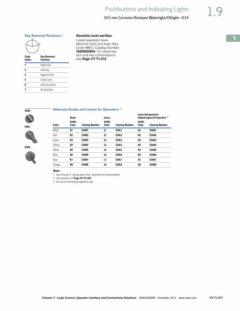
Volume 7—Logic Control, Operator Interface and Connectivity Solutions CA08100008E—December 2013 www.eaton.com V7-T1-277
1
1
1
1
1
1
1
1
1
1
1
1
1
1
1
1
1
1
1
1
1
1
1
1
1
1
1
1
1
1
1.9Pushbuttons and Indicating Lights
30.5 mm Corrosion Resistant Watertight/Oiltight—E34
Key Removal Positions 1 Dissimilar Locks and KeysListed operators have identical locks and keys (Key Code H661), Catalog Number 10250ED824. For dissimilar lock and key combinations, see Page V7-T1-212.
Alternate Knobs and Levers for Operators 2
Notes1 Key removal in “spring return from” positions not recommended.2 See operators on Page V7-T1-276.3 For use on maintained operators only.
CodeSuffix
Key RemovalPosition
1 Right only
2 Left only
3 Right and left
4 Center only
6 Left and center
7 All positions
L
C
R
Color
Knob LeverLever Designed for Added Ingress Protection 3
SuffixCode Catalog Number
SuffixCode Catalog Number
SuffixCode Catalog Number
Black K1 E34K1 L1 E34L1 A1 E34A1
Red K2 E34K2 L2 E34L2 A2 E34A2
Green K3 E34K3 L3 E34L3 A3 E34A3
Yellow K4 E34K4 L4 E34L4 A4 E34A4
White K5 E34K5 L5 E34L5 A5 E34A5
Blue K6 E34K6 L6 E34L6 A6 E34A6
Gray K7 E34K7 L7 E34L7 A7 E34A7
Orange K8 E34K8 L8 E34L8 A8 E34A8
E34K_
E34L_
E34A_

V7-T1-278 Volume 7—Logic Control, Operator Interface and Connectivity Solutions CA08100008E—December 2013 www.eaton.com
1
1
1
1
1
1
1
1
1
1
1
1
1
1
1
1
1
1
1
1
1
1
1
1
1
1
1
1
1
1
1.9 Pushbuttons and Indicating Lights
30.5 mm Corrosion Resistant Watertight/Oiltight—E34
Illuminated Selector Switch Operators
Operator without Knob or Lever
Knobs and Levers Light Unit Voltage Suffix
Add to operator Catalog Number listed in table above.
NotesUse NEMA 4X 10250T operators where exposed to ultraviolet light, see Pages V7-T1-182 to V7-T1-253.1 Full voltage light units can be used at other than listed voltages by changing lamp. Replacement lamps are listed on Page V7-T1-239.2 120MB lamps are used on both 120V and 240V operators.3 Operator includes lens gasket and lens attachment screws.4 Add suffix code for light unit voltage to listed catalog number from Light Unit Voltage Suffix table above.
Example: For 24V transformer type light unit, order E34VFB024.5 For selection of the proper cam and contact block required to obtain a specific circuit sequence, see selection tables on Pages V7-T1-273 to V7-T1-275.6 120 and 240V transformer only.7 120 full voltage only.8 Resistor type. May generate excess heat if used in high density.9 Amber, clear and white lenses have a black arrow (R). Red, green and blue lenses have a white arrow (R).
Positions Operator Action
Transformer Type—50/60 Hz Full Voltage Type—AC or DC 1
6V #755 Lamp Lamps—#755, #757, #1835, 120MB 2
Catalog Number 34 Catalog Number 4
Two-position—60° throw Cam Code 1 5 Cam Code 1 5
E34VFB_ E34SFB_
Three-position—60° throw Cam Code 2 5 Cam Code 3 5 Cam Code 2 5 Cam Code 3 5
E34VGB_ E34VHB_ E34SGB_ E34SHB_
E34VNB_ 6 E34VPB_ 6 E34SNB_ 7 E34SPB_ 7
E34VJB_ 6 E34VKB_ 6 E34SJB_ 7 E34SKB_ 7
E34VLB_ E34VMB_ E34SLB_ E34SMB_
Four-position—40° throw E34VRB_ — E34SRB_ —
120 Vac Transformer Selector Switch, Cam 1
M M
M M
M
M S
M
MS
M
S S
M
M M
M M
Color 9
KnobCatalog Numberand Code Number
LeverCatalog Numberand Code Number
Red 10250TER 10250TFR
Green 10250TEG 10250TFG
Yellow 10250TEA 10250TFA
Blue 10250TEL 10250TFL
Clear 10250TEC 10250TFC
White 10250TEW 10250TFW
Amber 10250TEM 10250TFM
Knob
Lever
Type of Light UnitTransformer Type50/60 Hz
Full Voltage TypeAC or DC 1
Voltage Suffix Code Voltage Suffix Code
24 024 6 06
120 120 12 12
208 208 24 24
240 240 48 48
380 380 120 120
480 480 240 8 240
600 600

Volume 7—Logic Control, Operator Interface and Connectivity Solutions CA08100008E—December 2013 www.eaton.com V7-T1-279
1
1
1
1
1
1
1
1
1
1
1
1
1
1
1
1
1
1
1
1
1
1
1
1
1
1
1
1
1
1
1.9Pushbuttons and Indicating Lights
30.5 mm Corrosion Resistant Watertight/Oiltight—E34
Accessories
Accessories
Notes1 Should not be used on flush button for STOP function.2 Not suitable for single contact block depth cast enclosure. Cover is too thick.
Description Catalog Number
Padlocking Attachment for Flush Pushbutton Operators. Permits locking NC contacts in open position with 1/4 in padlock. Will not lock NO contact.
E34TA2
Flexible Weather Resistant Boot for use with flush pushbutton operators.
Clear 10250TA46
Black 10250TA47
Red 10250TA48
Green 10250TA49
Flexible Weather Resistant Boot for use with button operators (extended buttons preferred).
Black 10250TA3
Red 10250TA4 1
Green 10250TA10
Clear 10250TA85
Transparent Boot for regular, illuminated pushbutton operators and PresTest. 10250TA25 2
Special Retaining Nut—to accommodate thick panel.
Indicating light E34TA30
PresTest, pushbuttons and selector switches E34TA31
Shroud for Mushroom Head Operator—prevents accidental operation. (Not for push-pull operators.)
E34TA6
Extended Retaining Nut—replaces standard nut and provides guard for flush type pushbutton operators.
E34TA12
Guard for illuminated pushbutton E34TA15
Padlocking Attachment for non-illuminated knob selector switches—accommodates up to five, 1/4 in padlocks.
E34TA11
E34TA2
10250TA_
E34TA3_
E34TA6
E34TA12
E34TA15
E34TA11

V7-T1-280 Volume 7—Logic Control, Operator Interface and Connectivity Solutions CA08100008E—December 2013 www.eaton.com
1
1
1
1
1
1
1
1
1
1
1
1
1
1
1
1
1
1
1
1
1
1
1
1
1
1
1
1
1
1
1.9 Pushbuttons and Indicating Lights
30.5 mm Corrosion Resistant Watertight/Oiltight—E34
Accessories, continued
Description Catalog Number
Thrust Washer—To meet Ford Motor Company mounting specifications. E34TK3
Contact Block Terminal Jumps—Available in multiples of 100 only.
Terminal to terminal—within block (short):
100 per package 10250TA70
1000 per package 10250TA70-2
Terminal to terminal—block to block (long):
100 per package 10250TA71
1000 per package 10250TA71-2
Master Test (Dual Input) Module—Internal Form C relay suitable for either AC or DC applications. Total electrical isolation between monitored and test circuit. Fits all illuminated 10250T, E22, E30 and E34 devices.
48 Vdc 10250TMT8
Flasher Module—Internal Form C relay suitable for AC applications. One unit required for each operator in master test circuit.
24 Vac 10250TFL2
120 Vac 10250TFL1
Panel Mounting Nut Wrench—E22, E30, E34 and octagonal 10250T. E22CW
Fingerproof Shroud—10 per packageFits new style contact blocks and light units.
10250TA101
E34TK3
10250TA7_
10250TMT8
10250TFL_
E22CW
10250TA101
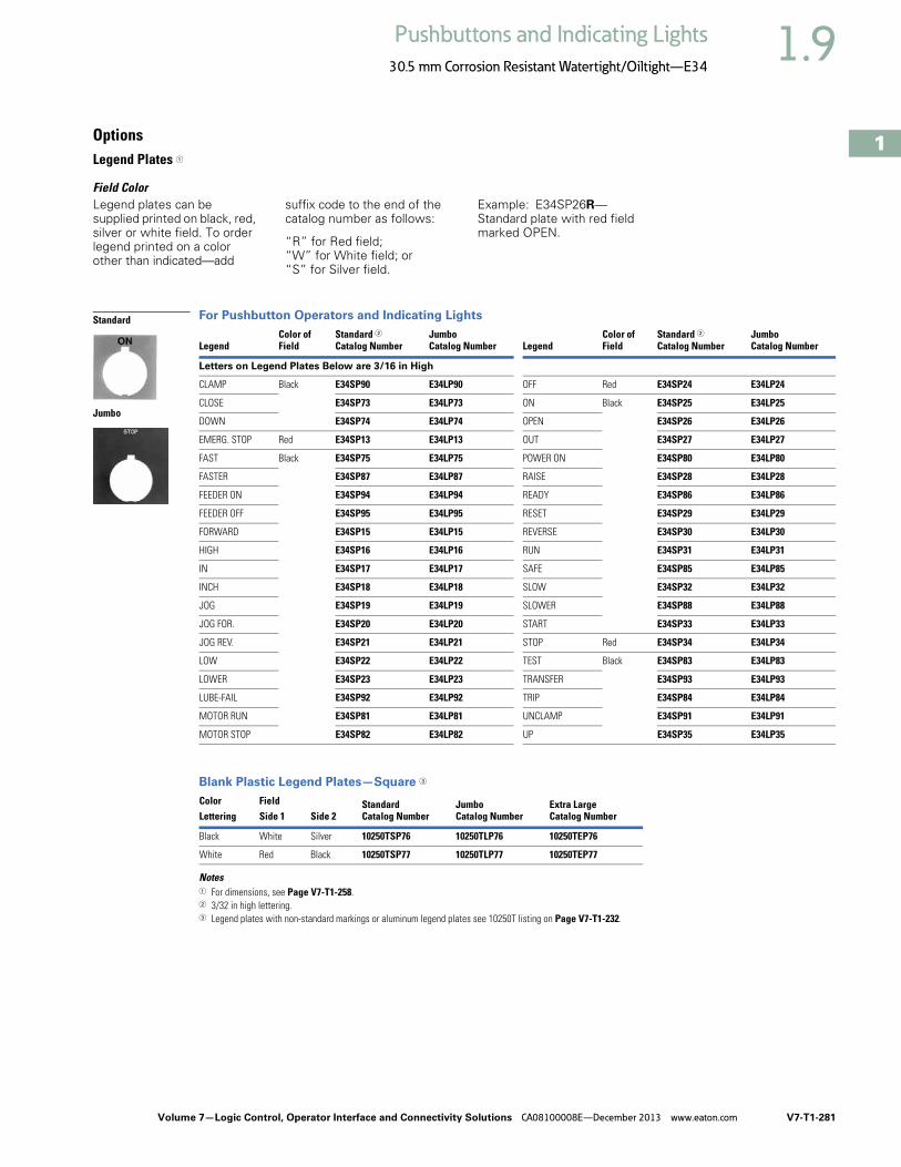
Volume 7—Logic Control, Operator Interface and Connectivity Solutions CA08100008E—December 2013 www.eaton.com V7-T1-281
1
1
1
1
1
1
1
1
1
1
1
1
1
1
1
1
1
1
1
1
1
1
1
1
1
1
1
1
1
1
1.9Pushbuttons and Indicating Lights
30.5 mm Corrosion Resistant Watertight/Oiltight—E34
OptionsLegend Plates 1
Field ColorLegend plates can be supplied printed on black, red, silver or white field. To order legend printed on a color other than indicated—add
suffix code to the end of the catalog number as follows:
“R” for Red field;“W” for White field; or“S” for Silver field.
Example: E34SP26R—Standard plate with red field marked OPEN.
For Pushbutton Operators and Indicating Lights
Blank Plastic Legend Plates—Square 3
Notes1 For dimensions, see Page V7-T1-258.2 3/32 in high lettering.3 Legend plates with non-standard markings or aluminum legend plates see 10250T listing on Page V7-T1-232.
LegendColor ofField
Standard 2Catalog Number
JumboCatalog Number Legend
Color ofField
Standard 2Catalog Number
JumboCatalog Number
Letters on Legend Plates Below are 3/16 in High
CLAMP Black E34SP90 E34LP90 OFF Red E34SP24 E34LP24
CLOSE E34SP73 E34LP73 ON Black E34SP25 E34LP25
DOWN E34SP74 E34LP74 OPEN E34SP26 E34LP26
EMERG. STOP Red E34SP13 E34LP13 OUT E34SP27 E34LP27
FAST Black E34SP75 E34LP75 POWER ON E34SP80 E34LP80
FASTER E34SP87 E34LP87 RAISE E34SP28 E34LP28
FEEDER ON E34SP94 E34LP94 READY E34SP86 E34LP86
FEEDER OFF E34SP95 E34LP95 RESET E34SP29 E34LP29
FORWARD E34SP15 E34LP15 REVERSE E34SP30 E34LP30
HIGH E34SP16 E34LP16 RUN E34SP31 E34LP31
IN E34SP17 E34LP17 SAFE E34SP85 E34LP85
INCH E34SP18 E34LP18 SLOW E34SP32 E34LP32
JOG E34SP19 E34LP19 SLOWER E34SP88 E34LP88
JOG FOR. E34SP20 E34LP20 START E34SP33 E34LP33
JOG REV. E34SP21 E34LP21 STOP Red E34SP34 E34LP34
LOW E34SP22 E34LP22 TEST Black E34SP83 E34LP83
LOWER E34SP23 E34LP23 TRANSFER E34SP93 E34LP93
LUBE-FAIL E34SP92 E34LP92 TRIP E34SP84 E34LP84
MOTOR RUN E34SP81 E34LP81 UNCLAMP E34SP91 E34LP91
MOTOR STOP E34SP82 E34LP82 UP E34SP35 E34LP35
Color Field StandardCatalog Number
JumboCatalog Number
Extra LargeCatalog NumberLettering Side 1 Side 2
Black White Silver 10250TSP76 10250TLP76 10250TEP76
White Red Black 10250TSP77 10250TLP77 10250TEP77
Standard
Jumbo
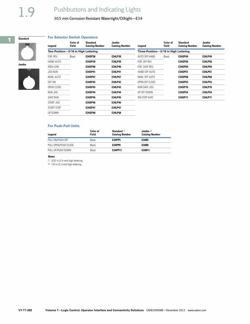
V7-T1-282 Volume 7—Logic Control, Operator Interface and Connectivity Solutions CA08100008E—December 2013 www.eaton.com
1
1
1
1
1
1
1
1
1
1
1
1
1
1
1
1
1
1
1
1
1
1
1
1
1
1
1
1
1
1
1.9 Pushbuttons and Indicating Lights
30.5 mm Corrosion Resistant Watertight/Oiltight—E34
For Selector Switch Operators
For Push-Pull Units
Notes1 3/32 in (2.4 mm) high lettering.2 1/8 in (3.2 mm) high lettering.
LegendColor ofField
StandardCatalog Number
JumboCatalog Number Legend
Color ofField
StandardCatalog Number
JumboCatalog Number
Two-Position—3/16 in High Lettering Three-Position—3/16 in High Lettering
FOR. REV. Black E34SP38 E34LP38 AUTO OFF HAND Black E34SP49 E34LP49
HAND AUTO E34SP39 E34LP39 FOR. OFF REV. E34SP50 E34LP50
HIGH LOW E34SP40 E34LP40 FOR. SAFE REV. E34SP69 E34LP69
JOG RUN E34SP41 E34LP41 HAND OFF AUTO E34SP51 E34LP51
MAN. AUTO E34SP67 E34LP67 MAN. OFF AUTO E34SP68 E34LP68
OFF ON E34SP42 E34LP42 OPEN OFF CLOSE E34SP53 E34LP53
OPEN CLOSE E34SP43 E34LP43 RUN SAFE JOG E34SP70 E34LP70
RUN JOG E34SP44 E34LP44 UP OFF DOWN E34SP54 E34LP54
SAFE RUN E34SP45 E34LP45 ON STOP SAFE E34SP71 E34LP71
START JOG E34SP46 E34LP46
START STOP E34SP47 E34LP47
UP DOWN E34SP48 E34LP48
LegendColor ofField
Standard 1Catalog Number
Jumbo 2Catalog Number
PULL ON/PUSH OFF Black E34PP5 E34R5
PULL OPEN/PUSH CLOSE Black E34PP8 E34R8
PULL UP/PUSH DOWN Black E34PP11 E34R11
Standard
Jumbo

Volume 7—Logic Control, Operator Interface and Connectivity Solutions CA08100008E—December 2013 www.eaton.com V7-T1-283
1
1
1
1
1
1
1
1
1
1
1
1
1
1
1
1
1
1
1
1
1
1
1
1
1
1
1
1
1
1
1.9Pushbuttons and Indicating Lights
30.5 mm Corrosion Resistant Watertight/Oiltight—E34
Enclosures
Die Cast, Polyester and Stainless Steel Enclosures
Enclosures (Case and Cover)—Surface Mounting 1
Mounting InstructionsThese E34 Die Cast Enclosures feature a corrosion resistant coating identical to finish on the E34 operators except gray in color. Not for use in ultraviolet light applications.
One and Two Contact Block Depth Enclosures Enclosure Layouts
Notes1 For spacing increments, see Page V7-T1-284.2 All die cast enclosures can be converted to base mounting of contact blocks with spacers 10250TA22 or 10250TA23.
See listing on Page V7-T1-227.3 When used with E30 pushbuttons, only the one element enclosure can be used.4 14 gauge, type 304.
Number ofElements
One Contact Block DepthCatalog Number
Two Contact Block DepthCatalog Number
Die Cast Enclosure—In-Line 23 NEMA 4, 4X, 12, 13
1 E34N1 E34N11
2 E34N2 E34N12
3 E34N3 E34N13
4 — E34N14
Polyester—In-Line NEMA 3, 4X, 12
1 — E34N51
2 — E34N52
3 — E34N53
4 — E34N54
Stainless Steel 4—In-Line NEMA 4, 4X, 12
1 — 10250TN33
2 — 10250TN34
3 — 10250TN35
4 — 10250TN36
Dimensions, see Page V7-T1-292.
Die Cast Enclosure
Polyester Enclosure
Stainless Steel Enclosure
One Contact Block Depth Enclosure
Two Contact Block Depth Enclosure
1 1 1
Top – For Vertical Mounting
To
p –
Fo
r Ho
rizon
tal
Mo
un
ting
1
2 2 2
3 3
4

V7-T1-284 Volume 7—Logic Control, Operator Interface and Connectivity Solutions CA08100008E—December 2013 www.eaton.com
1
1
1
1
1
1
1
1
1
1
1
1
1
1
1
1
1
1
1
1
1
1
1
1
1
1
1
1
1
1
1.9 Pushbuttons and Indicating Lights
30.5 mm Corrosion Resistant Watertight/Oiltight—E34
Die Cast and Stainless Steel—Flush Mount, Covers Only 1
Covers Only—Flush Mounting
Spacing Increments
Approximate Dimensions in Inches (mm)
Spacing Increments for Enclosures Enclosure Layouts
Notes1 These E34 die cast covers feature a corrosion resistant coating identical to the finish on the E34 operators except gray in color.2 Not oiltight. NEMA 1 applications only.
Number ofElements Catalog Number Catalog Number
Flush Die Cast Covers
In-Line Deep Cover
In-Line Flat Cover
1 E34F11 E34F1
2 E34F12 E34F2
3 E34F13 E34F3
4 E34F14 E34F4
In-Line Stainless Steel Flush Plates 2
With Pullbox Without Pullbox
1 10250TS10 10250TS1
2 10250TS11 10250TS2
3 10250TS12 10250TS3
4 10250TS14 10250TS4
Dimensions, see Page V7-T1-293.
Type F G H
Die cast 2.44 (62) 2.5 (63.5) 1.88 (47.8)
Polyester 1.88 (47.8) Min. 2.13 (54.1) 2.25 (57.2)
Stainless steel 1.69 (42.9) Min. 1.73 (43.9) 2.25 (57.2)
Flush Mounting Covers
F
G
H1 1 1
Top – For Vertical Mounting
To
p –
Fo
r Ho
rizon
tal
Mo
un
ting
1
2 2 2
3 3
4

Volume 7—Logic Control, Operator Interface and Connectivity Solutions CA08100008E—December 2013 www.eaton.com V7-T1-285
1
1
1
1
1
1
1
1
1
1
1
1
1
1
1
1
1
1
1
1
1
1
1
1
1
1
1
1
1
1
1.9Pushbuttons and Indicating Lights
30.5 mm Corrosion Resistant Watertight/Oiltight—E34
Contact Blocks
Standard Contact Blocks● UL A600/P600 rated● Color-coded plungers—red/
green for NC/NO circuits● Silver contact tips with
“reliability nibs”● Black (opaque) or amber
(translucent) housings● Pressure plate or spade
terminals● Fingerproof shrouds (for
pressure terminals only)
Logic Level Contact Blocks● UL A600/P600 rated● Black plungers● Inert palladium knife-blade
contacts ● Black (opaque) housings● Pressure plate or spade
terminals● Fingerproof shrouds not
available
Special Function Contact Blocks● UL A600/P600 rated● Black plungers● Silver contact tips with
“reliability nibs”● Black (opaque) housings● Pressure plate terminals
only● Fingerproof shrouds not
available
Special Purpose Contact Block● Maximum 300V rated● Black plungers● Silver contact tips with
“reliability nibs”● Black (opaque) housings● Pressure plate terminals
only● Fingerproof shrouds not
available
Reliability NibsReliability nibs are the hallmark of Eaton’s contact blocks. A pointed silver nib on the contact tip ensures reliable switching from logic level (5V) up to 600V applications. Therefore standard contact blocks can be used for most logic level applications where the contacts are not exposed to any harsh environmental conditions.
Palladium ContactsPalladium, which is more inert than gold, is well suited for voltages and currents approaching zero and is recommended for applications where environmental conditions are a factor.
Maximum Contact Block Mounting per Operator Type
OperatorMax. Stack
Pushbuttons 6
Push-pull operators 2
Roto-push operators 4
Two- or three-position selector switches
6
Four-position selector switches
4
Joysticks 4

V7-T1-286 Volume 7—Logic Control, Operator Interface and Connectivity Solutions CA08100008E—December 2013 www.eaton.com
1
1
1
1
1
1
1
1
1
1
1
1
1
1
1
1
1
1
1
1
1
1
1
1
1
1
1
1
1
1
1.9 Pushbuttons and Indicating Lights
30.5 mm Corrosion Resistant Watertight/Oiltight—E34
Contact Blocks
Notes1 All 10250T contact blocks shown are suitable for use on standard 10250T and E34 operators. These contact blocks are not suitable for Class I Division 2
type 10250T or E34 devices.2 Contact blocks with spade terminals are limited to a maximum of one contact block per operator and minimum spacing between devices is 2.5 in (63.5 mm).
Not suitable for use in 10250T or E34 enclosures. Also available in amber housing. Not available with fingerproof shrouds.3 Special function contact blocks are not suitable for use with roto-push operators, three-position push-pull operators, or four-position selector switches.4 ECNO contact blocks are not suitable for use with two-position joysticks or when operators are used with padlock attachments.5 Special purpose 10250T44 contact blocks are not suitable on selector switches or roto-push operators. Okay to use with three-position push-pull operators only
on low voltage (30V or less) circuits.
Symbol Circuit Description 1
Standard Logic LevelPressure TerminalCatalog Number
Spade Terminal 2Catalog Number
Pressure TerminalCatalog Number
Spade Terminal 2Catalog Number
1NC Stack up to six blocks (six circuits) unless otherwise noted.
10250T51 10250T59 10250T51E 10250T59E
1NO Stack up to six blocks six circuits) unless otherwise noted.
10250T53 10250T60 10250T53E 10250T60E
NO-NC Stack up to six blocks (12 circuits) unless otherwise noted.
10250T1 10250T40 10250T1E 10250T40E
2NC Stack up to six blocks (12 circuits) unless otherwise noted.
10250T3 10250T42 10250T3E 10250T42E
2NO Stack up to six blocks (12 circuits) unless otherwise noted.
10250T2 10250T41 10250T2E 10250T41E
Special Function Blocks 3
LONC Late opening NC. Stack up to six blocks (six circuits) unless otherwise noted.
10250T71 3 — 10250T71E 3 —
ECNO-NC
Early closing NO and standard NC. Stack up to six blocks unless otherwise noted.
10250T47 34 — 10250T47E 3 —
ECNO-NO
Early closing NO and standard NO. Stack up to four blocks unless otherwise noted.
10250T57 34 — 10250T57E 3 —
2LONC Two late opening NC contacts. Stack up to six blocks unless otherwise noted.
10250T45 3 — 10250T45E 3 —
LONC-ECNO
Overlapping contacts. Stack up to four blocks unless otherwise noted.
10250T55 34 — 10250T55E 3 —
Special Purpose Blocks 5
2NO-2NC
Four circuits in single block depth. Rated 300V max. Stack up to four blocks unless otherwise noted.
10250T44 5 —
10250T1
BlankNo
Plunger
BlankNo
Plunger
BlankNo
Plunger

Volume 7—Logic Control, Operator Interface and Connectivity Solutions CA08100008E—December 2013 www.eaton.com V7-T1-287
1
1
1
1
1
1
1
1
1
1
1
1
1
1
1
1
1
1
1
1
1
1
1
1
1
1
1
1
1
1
1.9Pushbuttons and Indicating Lights
30.5 mm Corrosion Resistant Watertight/Oiltight—E34
Contact Blocks with Fingerproof Shrouds
Replacement Parts
Replacement Lamps—For E34 Illuminated Operators
Notes1 All 10250T contact blocks shown are suitable for use on standard 10250T and E34 operators. These contact blocks are not suitable for Class I Division 2
type 10250T or E34 devices.2 To order contact blocks with translucent amber housing, change suffix P to CP in catalog number e.g. 10250T51CP.3 ECNO contact blocks are not suitable for use with two-position joysticks or when operators are used with padlock attachments.4 Special function contact blocks are not suitable for use with roto-push operators, three-position push-pull operators, or four-position selector switches.
Symbol Circuit Description 1
StandardPressure Terminal 2Catalog Number
Logic LevelPressure Terminal 2Catalog Number
1NC Stack up to six blocks (six circuits) unless otherwise noted. 10250T51P 10250T51EP
1NO Stack up to six blocks (six circuits) unless otherwise noted. 10250T53P 10250T53EP
NO-NC Stack up to six blocks (12 circuits) unless otherwise noted. 10250T1P 10250T1EP
2NC Stack up to six blocks (12 circuits) unless otherwise noted. 10250T3P 10250T3EP
2NO Stack up to six blocks (12 circuits) unless otherwise noted. 10250T2P 10250T2EP
Special Function Blocks 3
LONC Late opening NC. Stack up to six blocks (six circuits) unless otherwise noted.
10250T71P 4 10250T71EP 4
ECNO-NC Early closing NO and standard NC. Stack up to six blocks unless otherwise noted.
10250T47P 34 10250T47EP 4
ECNO-NO Early closing NO and standard NO. Stack up to four blocks unless otherwise noted.
10250T57P 34 10250T57EP 4
2LONC Two late opening NC contacts. Stack up to six blocks unless otherwise noted.
10250T45P 4 10250T45EP 4
LONC-ECNO Overlapping contacts. Stack up to four blocks unless otherwise noted.
10250T55P 34 10250T55EP 4
Mfg. Lamp Type Voltage Base Style Application Part Number
120MB 120V T 3-1/4 bayonet 10250T resistor indicating light 28-3044
#267 6.3V T 3-1/4 bayonet 10250T flasher 10250ED986-4
#755 6.3V T 3-1/4 bayonet 10250T transformer, PresTest and full voltage 28-2202
#756 12V T 3-1/4 bayonet 10250T full voltage 28-5184
#757 24V T 3-1/4 bayonet 10250T full voltage 28-5185
#1828 32V T 3-1/4 bayonet 10250T full voltage 28-5186
#1835 55V T 3-1/4 bayonet 10250T resistor 28-5187
NE48 120V T 4-1/2 bayonet 10250T neon 28-494
NE51H-R22 120V T 3-1/4 bayonet 10250T neon 28-3754
NE51H-R68 240V T 3-1/4 bayonet 10250T neon 28-3755
10250T1CP
BlankNo
Plunger
BlankNo
Plunger
BlankNo
Plunger

V7-T1-288 Volume 7—Logic Control, Operator Interface and Connectivity Solutions CA08100008E—December 2013 www.eaton.com
1
1
1
1
1
1
1
1
1
1
1
1
1
1
1
1
1
1
1
1
1
1
1
1
1
1
1
1
1
1
1.9 Pushbuttons and Indicating Lights
30.5 mm Corrosion Resistant Watertight/Oiltight—E34
E34 Style Operator Replacement Parts
Flush HeadPushbutton Operator
Mushroom HeadPushbutton Operator
Jumbo MushroomHead Operator
IlluminatedPushbutton Operator
Transformer TypeIndicating Light
Knob-Operated Selector SwitchOperator
Full Voltage, Resistorand Transformer TypeIlluminated Selector Switch
Potentiometers
ItemNo. Description
No.Req.
PartNumber
1 Gasket 1 16-1548
2 Mounting nut 1 15-1530-4
3 Set screw (#6-32 x 0.250 in long hollow hex) 2 11-2014
4 Mushroom head button (includes [2] item 5) 1 As Req. Below
Black — 53-1317
Red — 53-1317-2
Yellow — 53-1317-3
Green — 53-1317-4
Blue — 53-1317-22
5 Set screw (#10-32 x 0.250 in long hollow hex) 2 11-544
6 Jumbo mushroom head button (aluminum—includes [2] item 5)
1 As Req. Below
Red — 53-1317-9
Black — 53-1317-10
Yellow — 53-1317-11
Green — 53-1317-12
7 Jumbo mushroom head button (aluminum—red EMERG. STOP) does not include item 5
1 53-1349-18
8 Mounting screw (#6-32 x 0.710 in long) 2 10250TA79
Washer 2 16-2038
9 Terminal screw and lug (captive) Req. 80-5502
10 Gasket (supplied with basic unit) 1 32-803
11 Round head screw (#4-40 x 0.344 in long) (supplied with basic unit)
2 11-4553
ItemNo. Description
No.Req.
PartNumber
12 Mounting screw 2 11-1632
13 Simple potentiometer (does not include items 18, 28 or 29)
1 As Req. Below
1,000 ohms — 41-782-2
2,500 ohms — 41-782-3
5,000 ohms — 41-782-10
10,000 ohms — 41-782-4
25,000 ohms — 41-782-5
50,000 ohms — 41-782-6
14 Connector (includes screw and lug) 2 25-1851
15 Indicating plate 1 As Req. Above
Standard size (without legend) — 30-4460
Large size (specify legend) — 10250TR30
16 Retaining nut 1 15-1547-3
17 Knob 1 53-1314
Socket set screw (#6-32 x 0.250 in long) 1 11-2014
18 Coupling 1 11-2014
29-3749-2
19 Set screw (#6-32 x 0.188 in long) 1 11-1199
20 Spacer 2 56-1066-18
21 Connector (includes screw and lug) 1 25-1851-2
22 Mounting nut 1 15-1938-2

Volume 7—Logic Control, Operator Interface and Connectivity Solutions CA08100008E—December 2013 www.eaton.com V7-T1-289
1
1
1
1
1
1
1
1
1
1
1
1
1
1
1
1
1
1
1
1
1
1
1
1
1
1
1
1
1
1
1.9Pushbuttons and Indicating Lights
30.5 mm Corrosion Resistant Watertight/Oiltight—E34
Technical Data and Specifications
Mechanical Ratings
General Specifications
Description Specification
Frequency of Operation
All pushbuttons 6000 operations/hr.
Key and lever selector switches 3000 operations/hr.
Auto-latch devices 1200 operations/hr.
Life
Pushbuttons 10 x 106 operations
Contact blocks 10 x 106 operations
PresTest units 10 x 106 operations
Lever and key selector switches 0.25 x 10⁶ operations
Twist to release pushbuttons 0.3 x 10⁶ operations
Shock Resistance
Duration 210 ms >5g
Description Specification
Climate Conditions
Operating temperature 1° to 150°F (–17° to 66°C)
Storage temperature –40° to 176°F (–40° to 80°C)
Altitude 6,562 ft (2,000m)
Humidity Max. 95% RH at 60°C
Terminals
Marking NC-NO on the contact block to meet the NEMA requirements. Dual marking system 1–2 for normally closed, 3–4 for normally open to meet BS5472 (Cenelec EN50 005).
Clamps Terminals are saddle clamp type for 1 x 22 AWG (0.34 mm2) to 2 x 14 AWG (2.5 mm2) conductors
Torque 7 lb-in (0.8 Nm)
Degree of protection against direct electrical contact IP2X with fingerproof shroud
Light Units
Transformers Will withstand short-circuit for 1 hour per IEC 60947-5-1
Bulbs—average life:
Transformer type 20,000 hrs.
Resistor/direct voltage type 2500 hrs. minimum at rated V
LED 60,000 to 100,000 hrs.
V7-T1-290 Volume 7—Logic Control, Operator Interface and Connectivity Solutions CA08100008E—December 2013 www.eaton.com
1
1
1
1
1
1
1
1
1
1
1
1
1
1
1
1
1
1
1
1
1
1
1
1
1
1
1
1
1
1
1.9 Pushbuttons and Indicating Lights
30.5 mm Corrosion Resistant Watertight/Oiltight—E34
Electrical Ratings
Electrical Ratings—Contact Block
Description Specification
Insulation Ui = 660 Vac or Vdc
Thermal Ith = 10A
Short Circuit Coordination to IEC/EN 60947-5-1
Rated conditional short circuit current 1 kA
Fuse type GE power controls TIA 10, red spot type gG, 10A, 660 Vac, 460 Vdc, BS88-2, IEC 60269-2-1
UL rating A600, P600
AC load life duty cycle 1200 operations/hour
10A 110V pf 0.4—1 x 10⁶ operations
5A 250V pf 0.4—1 x 10⁶ operations
2A 600V pf 0.4—1 x 10⁶ operations
Switching capacity
AC 15 rated make/break (11 x le at 1.1 x Ue)
6A 120V pf 0.3
4A 240V pf 0.3
2A 660V pf 0.3
DC13 rated make/break (1.1 x le at 1.1 x Ue)
1.0A 125V L/R >0.95 at 300 ms
0.55A 250V L/R >0.95 at 300 ms
0.1A 660V L/R >0.95 at 300 ms
10A 110V pure resistive
Maximum ratings for logic level andhostile atmosphere application
Maximum amperes 0.5A
Maximum volts 120 Vac/Vdc
Low voltage switching Conical shaped points or “reliability nibs” improve performance in dry circuit, corrosive, fine dust and other contaminated atmospheres. Under normal environmental conditions, the minimum operational voltage is 5V and the minimum operational current is 1 mA, Vac/Vdc.
Contact operation Slow make and break. All normally closed contacts have positive opening operation, i.e., normally closed contacts are forced open in the event of contact weld or spring breakage.
Meet or Exceed NEMA Rating Designations A600, A300 and B300 for AC and P600 for DC
Description50 Vac or 60 H Vdc120 240 480 600 24/28 125 250
Meet or Exceed NEMA Rating Designations A600, A300 and B300 for AC and P600 for DC
Make and emerg. interrupting capacity (amp) 60 30 15 12 5.7 1.1 0.55
Normal load break (amp) 6 3 1.5 1.2 5.7 1.1 0.55
Thermal current (amp) 10 10 10 10 5.0 5.0 5.0
Voltamperes:
Make and emerg. interrupting capacity 7200 7200 7200 7200 138 138 138
Normal load break 720 720 720 720 138 138 138

Volume 7—Logic Control, Operator Interface and Connectivity Solutions CA08100008E—December 2013 www.eaton.com V7-T1-291
1
1
1
1
1
1
1
1
1
1
1
1
1
1
1
1
1
1
1
1
1
1
1
1
1
1
1
1
1
1
1.9Pushbuttons and Indicating Lights
30.5 mm Corrosion Resistant Watertight/Oiltight—E34
Mounting Options
Panel Thickness● Minimum: 0.06 in (1.6 mm)● Maximum: 0.25 in (8 mm) including legend plate● Maximum can be increased to 0.375 in (15.9 mm) using optional retaining nut
● Indicating light: 10250TA30● Pushbutton/selector switch: 10250TA31
Mounting Matrix
Mounting Options in Inches (mm)
Horizontal mounting means terminals are located top and bottom of contact block. Vertical mounting means terminals are left and right of contact block. This allows close spacing of adjacent operators with easy access to terminals.
Locating nib hole or notch is 0.14 in (3.6 mm) #29 drill.
Drilling Dimensions in Inches (mm)
LegendPlate
Dimensions in Inches (mm)A B C D
Small 1.63 (41.3) 2.25 (57.2) 2.25 (57.2) 1.63 (41.3)
Medium 1.75 (44.5) 2.25 (57.2) 2.25 (57.2) 1.75 (44.5)
Large 2.25 (57.2) 2.25 (57.2) 2.25 (57.2) 2.25 (57.2)
BMin.
CMin.
0.6(15.2)
AMin.
1.22(31)
DMin.
Horizontal Mounting Vertical Mounting
0.14 (3.6)Dia.
Terminals on Top
Terminals at Side
0.6(15.2)
1.20(30.5)
0.14 (3.6)Dia.

V7-T1-292 Volume 7—Logic Control, Operator Interface and Connectivity Solutions CA08100008E—December 2013 www.eaton.com
1
1
1
1
1
1
1
1
1
1
1
1
1
1
1
1
1
1
1
1
1
1
1
1
1
1
1
1
1
1
1.9 Pushbuttons and Indicating Lights
30.5 mm Corrosion Resistant Watertight/Oiltight—E34
DimensionsApproximate Dimensions in Inches (mm)
Potentiometer Legend Plates
Surface Mounting
Die Cast, Polyester and Stainless Steel Enclosures
Notes1 Depth given is for two contact block deep stations. One contact block deep stations subtract 3/4 in (19.1 mm).2 No conduit entrance holes provided. Drill as required.
1.88(47.8)
1.31(33.3)1.09
(27.7) 1.0(25.4)
0.75(19.1)
0.94(23.9)
0.94(23.9)
0.94(23.9)
Std. Dial Plate
Large Dial Plate 2.19(55.6)
Jumbo
2.19(55.6)
1.77(45)
Standard
1.77(45)
ASurface
D C
BE
4 Mtg. Holes — 10-32 Screw Size for 1 – 4 Element Die Cast/
Stainless Steel Enclosure7/32 Screw Size for
Polyester
Number ofElements
ElementArrangement
WideA
HighB
DeepC
Mounting ConduitEntranceD E
Die Cast
1 In-line 3.88 (98.6) 4.0 (101.6) 3.0 (76.3) 1 2.69 (68.3) 3.25 (82.6) 3/4
2 3.88 (98.6) 5.88 (149.4) 3.0 (76.3) 1 2.69 (68.3) 5.13 (130.3)
3 3.88 (98.6) 7.75 (196.9) 3.0 (76.3) 1 2.69 (68.3) 7.0 (177.8) 1
4 3.88 (98.6) 9.63 (244.6) 3.0 (76.3) 1 2.69 (68.3) 8.88 (225.6)
Polyester
1 In-line 3.81 (96.8) 6.63 (168.4) 3.38 (85.9) 2.94 (74.7) 4.88 (124.0) 2
2 3.81 (96.8) 6.63 (168.4) 3.38 (85.9) 2.94 (74.7) 4.88 (124.0)
3 3.81 (96.8) 8.88 (225.6) 3.38 (85.9) 2.94 (74.7) 7.13 (181.1)
4 3.81 (96.8) 11.13 (282.7) 3.38 (85.9) 2.94 (74.7) 9.38 (238.3)
Stainless Steel
1 In-line 3.00 (76.2) 3.50 (88.9) 3.00 (76.2) 1.50 (38.1) 4.25 (108.0) 2
2 3.50 (88.9) 6.75 (171.5) 3.00 (76.2) 1.50 (38.1) 7.50 (190.5)
3 3.50 (88.9) 9.00 (228.6) 3.00 (76.2) 1.50 (38.1) 9.00 (228.6)
4 3.50 (88.9) 11.25 (285.8) 3.00 (76.2) 1.50 (38.1) 12.00 (304.8)

Volume 7—Logic Control, Operator Interface and Connectivity Solutions CA08100008E—December 2013 www.eaton.com V7-T1-293
1
1
1
1
1
1
1
1
1
1
1
1
1
1
1
1
1
1
1
1
1
1
1
1
1
1
1
1
1
1
1.9Pushbuttons and Indicating Lights
30.5 mm Corrosion Resistant Watertight/Oiltight—E34
Approximate Dimensions in Inches (mm)
Flush Mounting
Die Case and Stainless Steel Covers Only
Notes1 Depth given is for flat cover. Deep cover is 3/4 in (19.1 mm) deeper.2 Depth given includes pull box.
ASurface or Pendant
D C
BE
4 Mtg. Holes - 10-32 Screw Sizefor 1-11 Element Encl, 1/4-20Screw Size for 12 Element
and Larger
Number ofElements
WideA
HighB
DeepC
MountingD E
Die Cast
1 3.88 (98.6) 4.0 (101.6) 0.25 (6.4) 1 3.50 (88.9) 3.63 (92.2)
2 3.88 (98.6) 5.88 (149.4) 0.25 (6.4) 1 3.50 (88.9) 5.50 (139.7)
3 3.88 (98.6) 7.75 (196.9) 0.25 (6.4) 1 3.50 (88.9) 6.0 (152.4)
4 3.88 (98.6) 9.63 (244.6) 0.25 (6.4) 1 3.50 (88.9) 9.25 (235)
Stainless Steel
1 5.00 (127) 5.0 (127 2.50 (63.5) 2 3.25 (82.6) 1.88 (47.8)
2 5.00 (127) 6.88 (174.8) 2.50 (63.5) 2 3.25 (82.6) 3.63 (92.2)
3 5.00 (127) 8.63 (219.2) 2.50 (63.5) 2 3.25 (82.6) 5.50 (139.7)
4 5.00 (127) 10.50 (266.7) 2.50 (63.5) 2 3.25 (82.6) 7.25 (184.2)

V7-T1-294 Volume 7—Logic Control, Operator Interface and Connectivity Solutions CA08100008E—December 2013 www.eaton.com
1
1
1
1
1
1
1
1
1
1
1
1
1
1
1
1
1
1
1
1
1
1
1
1
1
1
1
1
1
1
1.9 Pushbuttons and Indicating Lights
30.5 mm Corrosion Resistant Watertight/Oiltight—E34
Approximate Dimensions in Inches (mm)
Padlocking Attachment for Flush Pushbutton Operators
Flexible Weather Resistant Boot
Transparent Boot
Shroud for Mushroom Head Operator
Extended Retaining Nut
Guard for Illuminated Pushbutton
Contact Block Terminal Jumps
Master Test Module and Flasher Module
Flush Pushbutton
Extended Pushbutton
Half Shroud Pushbutton
0.75(19.1)
0.84(21.3) 0.94
(23.9)
1.63(41.4)
0.25(6.4)
1.47(37.3)
1.59(40.4)
1.92(48.8)
1.59(40.4)
1.53(38.9)
1.50(38.1)
1.25(31.8)
1.31(33.3)
1.38(35.1)
1.63(41.4)
1.50(38.1)
0.25(6.4)0.25
(6.4)
0.86(21.8)
0.45(11.4)
1.63(41.4)
1.14(29)
6 Mounting Holes
1.78(45.2)
1.31(33.3)
0.88(22.4)
1.09(27.7)
1.06(26.9)
1.78(45.2)
1.38(35.1)
Co
nta
ct
Blk
.
Each
Ad
dl.
Co
nta
ct B
lk.
0.88(22.4)
1.09(27.7)
1.44(36.6)
1.78(45.2)
1.38(35.1)
Co
nta
ct
Blk
.
Each
Ad
dl.
Co
nta
ct B
lk.
0.88(22.4)
1.09(27.7)
1.44(36.6)
1.78(45.2)
1.38(35.1)
Co
nta
ct
Blk
.
Each
Ad
dl.
Co
nta
ct B
lk.

Volume 7—Logic Control, Operator Interface and Connectivity Solutions CA08100008E—December 2013 www.eaton.com V7-T1-295
1
1
1
1
1
1
1
1
1
1
1
1
1
1
1
1
1
1
1
1
1
1
1
1
1
1
1
1
1
1
1.9Pushbuttons and Indicating Lights
30.5 mm Corrosion Resistant Watertight/Oiltight—E34
Approximate Dimensions in Inches (mm)
Mushroom Pushbutton
Jumbo Mushroom Pushbutton
Push-Pull Switch
Indicating Light
PresTest Indicating Light
Illuminated Pushbutton
Selector Switch
Key Selector Switch
Illuminated Selector Switch
0.88(22.4)
1.09(27.7)
1.63(41.4)
1.78(45.2)
1.50(38.1)
Co
nta
ct
Blk
.
Each
Ad
dl.
Co
nta
ct B
lk.
0.88(22.4)
1.09(27.7)
1.75(44.5)
1.78(45.2)
2.50(63.5)
Co
nta
ct
Blk
.
Each
Ad
dl.
Co
nta
ct B
lk.
2.63(66.8)
1.65(41.9)
1.78(45.2)
0.25(6.4)
0.06 (1.5) to 0.25 (6.4)Panel Thickness
0.88(22.4)
0.88(22.4)
1.13(28.7)
LightUnit
ContactBlock
1.38(35.1)
1.1(27.9)
1.78(45.2)
1.38(35.1)
1.9(48.3)
1.09(27.7)
0.69(17.5)
1.78(45.2)
1.38(35.1)
1.13(28.7)
Co
nta
ct
Blk
.
Each
Ad
dl.
Co
nta
ct B
lk.
1.09(27.7)
1.09(27.7)
0.69(17.5)
1.78(45.2)
1.38(35.1)
1.13(28.7)
Lig
ht
Un
it
1.58(40.1)Knob
1.58(40.1)Lever
1.09(27.7)
0.88(22.4)
Co
nta
ct
Blo
ck
Ea
ch A
dd
ition
al
Co
nta
ct B
lock
1.5(38.1)
1.58 (40.1)to Remove
Key
1.09(27.7)
0.88(22.4)
Co
nta
ct
Blo
ck
Ea
ch A
dd
l.C
on
tact B
lk.
1.58(40.1)Knob
1.58(40.1)Lever
1.09(27.7)
0.88(22.4)
Lig
ht
Un
it
Ea
ch A
dd
ition
al
Co
nta
ct B
lock
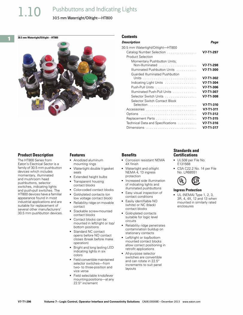
V7-T1-296 Volume 7—Logic Control, Operator Interface and Connectivity Solutions CA08100008E—December 2013 www.eaton.com
1
1
1
1
1
1
1
1
1
1
1
1
1
1
1
1
1
1
1
1
1
1
1
1
1
1
1
1
1
1
1.10 Pushbuttons and Indicating Lights
30.5 mm Watertight/Oiltight—HT800
30.5 mm Watertight/Oiltight—HT800 ContentsDescription Page
30.5 mm Watertight/Oiltight—HT800Catalog Number Selection . . . . . . . . . . . . . . . . V7-T1-297
Product Selection Momentary Pushbutton Units,
Non-Illuminated . . . . . . . . . . . . . . . . . . . . V7-T1-298
Illuminated Pushbutton Units . . . . . . . . . . . V7-T1-300
Guarded Illuminated Pushbutton Units . . . . . . . . . . . . . . . . . . . . . . . . . . . . . V7-T1-302
Indicating Light Units . . . . . . . . . . . . . . . . . V7-T1-304
Push-Pull Units . . . . . . . . . . . . . . . . . . . . . . V7-T1-306
Illuminated Push-Pull Units . . . . . . . . . . . . . V7-T1-307
Selector Switch Units . . . . . . . . . . . . . . . . . V7-T1-308
Selector Switch Contact Block Selection . . . . . . . . . . . . . . . . . . . . . . . . . . V7-T1-310
Accessories . . . . . . . . . . . . . . . . . . . . . . . . . . . V7-T1-311
Options . . . . . . . . . . . . . . . . . . . . . . . . . . . . . . V7-T1-312
Replacement Parts . . . . . . . . . . . . . . . . . . . . . . V7-T1-315
Technical Data and Specifications . . . . . . . . . . V7-T1-316
Dimensions . . . . . . . . . . . . . . . . . . . . . . . . . . . V7-T1-317
Product DescriptionThe HT800 Series from Eaton’s Electrical Sector is a family of 30.5 mm pushbutton devices which includes momentary, illuminated and mushroom head pushbuttons, selector switches, indicating lights and push-pull switches. The HT800 devices have a familiar appearance found in most industrial applications and are suitable for replacement of several other manufacturers’ 30.5 mm pushbutton devices.
Features● Anodized aluminum
mounting rings● Watertight double V-gasket
seals● Extended height bulbs● Transparent housing
contact blocks● Color-coded contact blocks● Gold-plated contacts (on
low voltage contact block)● Reliability ridge on movable
contact● Stackable screw-mounted
contact blocks● Contact blocks can be
mounted in left/right or top/bottom positions
● Standard NC contact opens before NO contact closes (break before make operation)
● Bright and long lasting LED indicating lights in six colors
● Field convertible maintained selector switches—from two- to three-position and vice versa
● Field selectable knob/lever mounting positions—at any 22.5° increment
Benefits● Corrosion resistant NEMA
4X finish● Watertight and oiltight
NEMA 4, 13 ingress protection
● Increased side illumination of indicating lights and illuminated pushbuttons
● Easy visual inspection of contact conditions
● Easily identifiable NO (white) or NC (black) contact blocks
● Gold-plated contacts suitable for logic level circuits
● Reliability ridge penetrates contamination buildup on stationary contacts
● Left/right or top/bottom mounted contact blocks allow correct positioning in retrofit applications
● All-purpose selector switches are convertible and can rotate in 22.5° increments to suit panel layouts
Standards and Certifications● UL508 per File No.
E131568● CSA C22.2 No. 14 per File
No. LR68551
Ingress Protection ● UL (NEMA) Type 1, 2, 3,
3R, 4, 4X, 12 and 13 when mounted in similarly rated enclosures

Volume 7—Logic Control, Operator Interface and Connectivity Solutions CA08100008E—December 2013 www.eaton.com V7-T1-297
1
1
1
1
1
1
1
1
1
1
1
1
1
1
1
1
1
1
1
1
1
1
1
1
1
1
1
1
1
1
1.10Pushbuttons and Indicating Lights
30.5 mm Watertight/Oiltight—HT800
Catalog Number SelectionCatalog Number Selection is for illustrative purposes only and not to be used to create new catalog numbers.
HT800 Pushbuttons, Push-Pulls and Indicating Lights
HT800 Selector Switch
Notes1 Maximum of four contact blocks per side or a total of eight contact blocks recommended. 2 Maximum of two contact blocks per side or a total of four contacts blocks recommended.
StylePushbuttonsAA = FlushAB = ExtendedAE = Mushroom head
Illuminated PushbuttonsGB = Illuminated PB
Push-Pull OperatorsCB = Two-position, maintained
Indicating LightsHF = Full voltage/resistor typeHB = Transformer type
Push-to-Test OperatorsGT = All types
Light Unit Type/VoltageF3 = 24V FV, LEDF7 = 120V FV, LEDL1 = 120V transformer, LEDT1 = 120V transformer, incandescentV3 = 24V FV, incandescentV7 = 120V res., incandescent
Button ColorG = GreenH = BlackR = Red
Lens ColorA = Amber/OrangeB = BlueC = ClearG = GreenR = Red
W = WhiteY = Yellow
Contact Block Location(viewed from rear) 1
Left Side Right SideA = NO
A2 = 2NOB1 = NCB2 = 2NC
C = NOEMC2 = 2 NOEMD1 = NCLBD2 = 2NCLBE1 = NOEM-NCLBF1 = NO and NCF4 = 1NO-1NC
A5 = NOA6 = 2NO
B = NCB6 = 2NCC5 = NOEMC6 = 2 NOEMD = NCLB
D6 = 2NCLBE5 = NOEM-NCLBQ1 = NO and NC
HT8 GB R AB T1
OperatorJA = Two-pos., knob, maint.JB = Three-pos., knob, maint.JC = Four-pos., knob, maint.JD = Two-pos., lever, maint.JE = Three-pos., lever, maint.JF = Four-pos., lever, maint.JK = Two-pos., knob, spr. rtn., leftJL = Two-pos., lever, spr. rtn., left
JN = Two-pos., knob, spr. rtn., rightJP = Two-pos., lever, spr. rtn., rightJR = Three-pos., knob, spr. rtn., leftJS = Three-pos., lever, spr. rtn., leftJU = Three-pos., knob, spr. rtn., rightJV = Three-pos., lever, spr. rtn., rightJX = Three-pos., knob, spr. rtn., bothJY = Three-pos., lever, spr. rtn., bothLN = Four-pos., knob, spr. rtn., pos 1 to 2LP = Four-pos., lever, spr. rtn., pos 1 to 2LR = Four-pos., knob, spr. rtn., pos 4 to 3LS = Four-pos., lever, spr. rtn., pos 4 to 3
Switch ColorH = Black Cam Location/Type
1D = For all three-pos.3A = For all two-pos.8E = For all four-pos.
Contact Block Location(viewed from rear) 2
Left Side Right SideA = NO
A2 = 2NOB1 = NCB2 = 2NC
C = NOEMC2 = 2 NOEMD1 = NCLBD2 = 2NCLBE1 = NOEM-NCLBF1 = NO and NCF4 = 1NO-1NC
A5 = NOA6 = 2NOB = NC
B6 = 2NCC5 = NOEMC6 = 2 NOEMD = NCLB
D6 = 2NCLBE5 = NOEM-NCLBQ1 = NO and NC
HT8 JA H 3A F1Q1

V7-T1-298 Volume 7—Logic Control, Operator Interface and Connectivity Solutions CA08100008E—December 2013 www.eaton.com
1
1
1
1
1
1
1
1
1
1
1
1
1
1
1
1
1
1
1
1
1
1
1
1
1
1
1
1
1
1
1.10 Pushbuttons and Indicating Lights
30.5 mm Watertight/Oiltight—HT800
Product SelectionMomentary Pushbutton Units, Non-IlluminatedUL (NEMA) Type 3, 3R, 4, 4X, 12 and 13
● Flush, extended or 40 mm mushroom head operators
HT800 Pushbuttons—Point-of-Purchase Units
Description Catalog Number
Two-position maintained selector switch 1NO/1NC contact block, three square legendplates: OFF ON, MAN. AUTO, UP DOWN
HT8JAH3AAB-POP
Three-position maintained selector switch, black knob, 1NO/1NC contact block, three square legend plates: HAND OFF AUTO, FOR. OFF REV., OPEN OFF CLOSE
HT8JBH1DAB-POP
Three-position selector switch, spring return from left and right, black knob, 1NO/1NC contact block, three square legend plates: UP OFF DOWN, FOR OFF REV., OPEN OFF CLOSE
HT8JXH1DAB-POP
Red push-pull emergency stop, 1NO/1NC contact block, three square legend plates: STOP, EMERG. STOP, OFF
HT8CBRAB-POP
Illuminated push-pull maintained red pushbutton, 120V full voltage low profile LED, three square legend plates: STOP, EMERG. STOP, OFF
HT8FBRABFL7-POP
Illuminated push-pull maintained red pushbutton, 24V full voltage low profile LED, three square legend plates: STOP, EMERG. STOP, OFF
HT8FBRABFL3-POP
Green flush pushbutton, 1NO/1NC contact block, three square legend plates: START, ON, RUN
HT8AAGAB-POP
Black flush pushbutton, 1NO/1NC contact block, three square legend plates: RESET, JOG, OPEN
HT8AAHAB-POP
Red flush pushbutton, 1NO/1NC contact block, three square legend plates: STOP, CLOSE, OFF
HT8AARAB-POP
Red extended pushbutton, 1NO/1NC contact block, three square legend plates: STOP, CLOSE, OFF
HT8ABRAB-POP
Black extended pushbutton, 1NO/1NC contact block, three square legend plates: RESET, JOG, OPEN
HT8ABHAB-POP
Illuminated green pushbutton, 120V full voltage incandescent, 1NO/1NC contact block, three square legend plates: START, ON, RUN
HT8GBGABV7-POP
Illuminated green pushbutton, 24V full voltage incandescent, 1NO/1NC contact block, three square legend plates: START, ON, RUN
HT8GBGABV3-POP
HT800 Pushbuttons

Volume 7—Logic Control, Operator Interface and Connectivity Solutions CA08100008E—December 2013 www.eaton.com V7-T1-299
1
1
1
1
1
1
1
1
1
1
1
1
1
1
1
1
1
1
1
1
1
1
1
1
1
1
1
1
1
1
1.10Pushbuttons and Indicating Lights
30.5 mm Watertight/Oiltight—HT800
Momentary Contact Pushbutton Units, Non-Illuminated
Contact Type Button ColorFlush HeadCatalog Number
Extended HeadCatalog Number
Mushroom Head (40 mm)Catalog Number
No contact Black HT8AAH HT8ABH HT8AEH
Red HT8AAR HT8ABR HT8AER
Green HT8AAG HT8ABG HT8AEG
1NO Black HT8AAHA HT8ABHA HT8AEHA
Red HT8AARA HT8ABRA HT8AERA
Green HT8AAGA HT8ABGA HT8AEGA
1NC Black HT8AAHB HT8ABHB HT8AEHB
Red HT8AARB HT8ABRB HT8AERB
Green HT8AAGB HT8ABGB HT8AEGB
1NO-1NC Black HT8AAHAB HT8ABHAB HT8AEHAB
Red HT8AARAB HT8ABRAB HT8AERAB
Green HT8AAGAB HT8ABGAB HT8AEGAB
2NO-2NC Black HT8AAHF1Q1 HT8ABHF1Q1 HT8AEHF1Q1
Red HT8AARF1Q1 HT8ABRF1Q1 HT8AERF1Q1
Green HT8AAGF1Q1 HT8ABGF1Q1 HT8AEGF1Q1
Flush Head Operator
Extended Head Operator
40 mm Mushroom Head Operator

V7-T1-300 Volume 7—Logic Control, Operator Interface and Connectivity Solutions CA08100008E—December 2013 www.eaton.com
1
1
1
1
1
1
1
1
1
1
1
1
1
1
1
1
1
1
1
1
1
1
1
1
1
1
1
1
1
1
1.10 Pushbuttons and Indicating Lights
30.5 mm Watertight/Oiltight—HT800
Illuminated Pushbutton UnitsUL (NEMA) Type 3, 3R, 4, 4X, 12 and 13
● Incandescent or LED● Full voltage or transformer type● 24V and 120V
Illuminated Pushbuttons
Note1 Light unit base operator without lens or bulb.
Type Volts Lens ColorOperator OnlyCatalog Number
1NOCatalog Number
1NCCatalog Number
1NO-1NCCatalog Number
2NO-2NCCatalog Number
Incandescent Lamp
Full voltage 120 Vac/Vdc No lens 1 HT8GBFV — — — —
Red HT8GBRV7 HT8GBRAV7 HT8GBRBV7 HT8GBRABV7 HT8GBRF1Q1V7
Green HT8GBGV7 HT8GBGAV7 HT8GBGBV7 HT8GBGABV7 HT8GBGF1Q1V7
Amber HT8GBAV7 HT8GBAAV7 HT8GBABV7 HT8GBAABV7 HT8GBAF1Q1V7
Clear HT8GBCV7 HT8GBCAV7 HT8GBCBV7 HT8GBCABV7 HT8GBCF1Q1V7
White HT8GBWV7 HT8GBWAV7 HT8GBWBV7 HT8GBWABV7 HT8GBWF1Q1V7
Yellow HT8GBYV7 HT8GBYAV7 HT8GBYBV7 HT8GBYABV7 HT8GBYF1Q1V7
Blue HT8GBBV7 HT8GBBAV7 HT8GBBBV7 HT8GBBABV7 HT8GBBF1Q1V7
24 Vac/Vdc No lens 1 HT8GBFV — — — —
Red HT8GBRV3 HT8GBRAV3 HT8GBRBV3 HT8GBRABV3 HT8GBRF1Q1V3
Green HT8GBGV3 HT8GBGAV3 HT8GBGBV3 HT8GBGABV3 HT8GBGF1Q1V3
Amber HT8GBAV3 HT8GBAAV3 HT8GBABV3 HT8GBAABV3 HT8GBAF1Q1V3
Clear HT8GBCV3 HT8GBCAV3 HT8GBCBV3 HT8GBCABV3 HT8GBCF1Q1V3
White HT8GBWV3 HT8GBWAV3 HT8GBWBV3 HT8GBWABV3 HT8GBWF1Q1V3
Yellow HT8GBYV3 HT8GBYAV3 HT8GBYBV3 HT8GBYABV3 HT8GBYF1Q1V3
Blue HT8GBBV3 HT8GBBAV3 HT8GBBBV3 HT8GBBABV3 HT8GBBF1Q1V3
Transformer 120 Vac No lens 1 HT8GBT1 — — — —
Red HT8GBRT1 HT8GBRAT1 HT8GBRBT1 HT8GBRABT1 HT8GBRF1Q1T1
Green HT8GBGT1 HT8GBGAT1 HT8GBGBT1 HT8GBGABT1 HT8GBGF1Q1T1
Amber HT8GBAT1 HT8GBAAT1 HT8GBABT1 HT8GBAABT1 HT8GBAF1Q1T1
Clear HT8GBCT1 HT8GBCAT1 HT8GBCBT1 HT8GBCABT1 HT8GBCF1Q1T1
White HT8GBWT1 HT8GBWAT1 HT8GBWBT1 HT8GBWABT1 HT8GBWF1Q1T1
Yellow HT8GBYT1 HT8GBYAT1 HT8GBYBT1 HT8GBYABT1 HT8GBYF1Q1T1
Blue HT8GBBT1 HT8GBBAT1 HT8GBBBT1 HT8GBBABT1 HT8GBBF1Q1T1
Illuminated Pushbutton Operator

Volume 7—Logic Control, Operator Interface and Connectivity Solutions CA08100008E—December 2013 www.eaton.com V7-T1-301
1
1
1
1
1
1
1
1
1
1
1
1
1
1
1
1
1
1
1
1
1
1
1
1
1
1
1
1
1
1
1.10Pushbuttons and Indicating Lights
30.5 mm Watertight/Oiltight—HT800
UL (NEMA) Type 3, 3R, 4, 4X, 12 and 13
Illuminated Pushbuttons, continued
Note1 Light unit base operator without lens or bulb.
Type Volts Lens ColorOperator OnlyCatalog Number
1NOCatalog Number
1NCCatalog Number
1NO-1NCCatalog Number
2NO-2NCCatalog Number
LED
Full voltage 120 Vac/Vdc No lens 1 HT8GBFV — — — —
Red HT8GBRF7 HT8GBRAF7 HT8GBRBF7 HT8GBRABF7 HT8GBRF1Q1F7
Green HT8GBGF7 HT8GBGAF7 HT8GBGBF7 HT8GBGABF7 HT8GBGF1Q1F7
Amber HT8GBAF7 HT8GBAAF7 HT8GBABF7 HT8GBAABF7 HT8GBAF1Q1F7
Clear HT8GBCF7 HT8GBCAF7 HT8GBCBF7 HT8GBCABF7 HT8GBCF1Q1F7
White HT8GBWF7 HT8GBWAF7 HT8GBWBF7 HT8GBWABF7 HT8GBWF1Q1F7
Yellow HT8GBYF7 HT8GBYAF7 HT8GBYBF7 HT8GBYABF7 HT8GBYF1Q1F7
Blue HT8GBBF7 HT8GBBAF7 HT8GBBBF7 HT8GBBABF7 HT8GBBF1Q1F7
24 Vac/Vdc No lens 1 HT8GBFV — — — —
Red HT8GBRF3 HT8GBRAF3 HT8GBRBF3 HT8GBRABF3 HT8GBRF1Q1F3
Green HT8GBGF3 HT8GBGAF3 HT8GBGBF3 HT8GBGABF3 HT8GBGF1Q1F3
Amber HT8GBAF3 HT8GBAAF3 HT8GBABF3 HT8GBAABF3 HT8GBAF1Q1F3
Clear HT8GBCF3 HT8GBCAF3 HT8GBCBF3 HT8GBCABF3 HT8GBCF1Q1F3
White HT8GBWF3 HT8GBWAF3 HT8GBWBF3 HT8GBWABF3 HT8GBWF1Q1F3
Yellow HT8GBYF3 HT8GBYAF3 HT8GBYBF3 HT8GBYABF3 HT8GBYF1Q1F3
Blue HT8GBBF3 HT8GBBAF3 HT8GBBBF3 HT8GBBABF3 HT8GBBF1Q1F3
Transformer 120 Vac No lens 1 HT8GBT1 — — — —
Red HT8GBRL1 HT8GBRAL1 HT8GBRBL1 HT8GBRABL1 HT8GBRF1Q1L1
Green HT8GBGL1 HT8GBGAL1 HT8GBGBL1 HT8GBGABL1 HT8GBGF1Q1L1
Amber HT8GBAL1 HT8GBAAL1 HT8GBABL1 HT8GBAABL1 HT8GBAF1Q1L1
Clear HT8GBCL1 HT8GBCAL1 HT8GBCBL1 HT8GBCABL1 HT8GBCF1Q1L1
White HT8GBWL1 HT8GBWAL1 HT8GBWBL1 HT8GBWABL1 HT8GBWF1Q1L1
Yellow HT8GBYL1 HT8GBYAL1 HT8GBYBL1 HT8GBYABL1 HT8GBYF1Q1L1
Blue HT8GBBL1 HT8GBBAL1 HT8GBBBL1 HT8GBBABL1 HT8GBBF1Q1L1
Illuminated Pushbutton Operator

V7-T1-302 Volume 7—Logic Control, Operator Interface and Connectivity Solutions CA08100008E—December 2013 www.eaton.com
1
1
1
1
1
1
1
1
1
1
1
1
1
1
1
1
1
1
1
1
1
1
1
1
1
1
1
1
1
1
1.10 Pushbuttons and Indicating Lights
30.5 mm Watertight/Oiltight—HT800
Guarded Illuminated Pushbutton UnitsUL (NEMA) Type 3, 3R, 4, 4X, 12 and 13
● Incandescent or LED● Full voltage or transformer type● 24V and 120V
Guarded Illuminated Pushbuttons
Note1 Light unit base operator without lens or bulb.
Type Volts Lens ColorOperator OnlyCatalog Number
1NOCatalog Number
1NCCatalog Number
1NO-1NCCatalog Number
2NO-2NCCatalog Number
Incandescent Lamp
Full voltage 120 Vac/Vdc No lens 1 HT8GDFV — — — —
Red HT8GDRV7 HT8GDRAV7 HT8GDRBV7 HT8GDRABV7 HT8GDRF1Q1V7
Green HT8GDGV7 HT8GDGAV7 HT8GDGBV7 HT8GDGABV7 HT8GDGF1Q1V7
Amber HT8GDAV7 HT8GDAAV7 HT8GDABV7 HT8GDAABV7 HT8GDAF1Q1V7
Clear HT8GDCV7 HT8GDVAV7 HT8GDCBV7 HT8GDCABV7 HT8GDCF1Q1V7
White HT8GDWV7 HT8GDWAV7 HT8GDWBV7 HT8GDWABV7 HT8GDWF1Q1V7
Yellow HT8GDYV7 HT8GDYAV7 HT8GDYBV7 HT8GDYABV7 HT8GDYF1Q1V7
Blue HT8GDBV7 HT8GDBAV7 HT8GDBBV7 HT8GDBABV7 HT8GDBF1Q1V7
24 Vac/Vdc No lens 1 HT8GDFV — — — —
Red HT8GDRV3 HT8GDRAV3 HT8GDRBV3 HT8GDRABV3 HT8GDRF1Q1V3
Green HT8GDGV3 HT8GDGAV3 HT8GDGBV3 HT8GDGABV3 HT8GDGF1Q1V3
Amber HT8GDAV3 HT8GDAAV3 HT8GDABV3 HT8GDAABV3 HT8GDAF1Q1V3
Clear HT8GDCV3 HT8GDVAV3 HT8GDCBV3 HT8GDCABV3 HT8GDCF1Q1V3
White HT8GDWV3 HT8GDWAV3 HT8GDWBV3 HT8GDWABV3 HT8GDWF1Q1V3
Yellow HT8GDYV3 HT8GDYAV3 HT8GDYBV3 HT8GDYABV3 HT8GDYF1Q1V3
Blue HT8GDBV3 HT8GDBAV3 HT8GDBBV3 HT8GDBABV3 HT8GDBF1Q1V3
Transformer 120 Vac No lens 1 HT8GDT1 — — — —
Red HT8GDRT1 HT8GDRAT1 HT8GDRBT1 HT8GDRABT1 HT8GDRF1Q1T1
Green HT8GDGT1 HT8GDGAT1 HT8GDGBT1 HT8GDGABT1 HT8GDGF1Q1T1
Amber HT8GDAT1 HT8GDAAT1 HT8GDABT1 HT8GDAABT1 HT8GDAF1Q1T1
Clear HT8GDCT1 HT8GDCAT1 HT8GDCBT1 HT8GDCABT1 HT8GDCF1Q1T1
White HT8GDWT1 HT8GDWAT1 HT8GDWBT1 HT8GDWABT1 HT8GDWF1Q1T1
Yellow HT8GDYT1 HT8GDYAT1 HT8GDYBT1 HT8GDYABT1 HT8GDYF1Q1T1
Blue HT8GDBT1 HT8GDBAT1 HT8GDBBT1 HT8GDBABT1 HT8GDBF1Q1T1
Guarded Illuminated Pushbutton Operator

Volume 7—Logic Control, Operator Interface and Connectivity Solutions CA08100008E—December 2013 www.eaton.com V7-T1-303
1
1
1
1
1
1
1
1
1
1
1
1
1
1
1
1
1
1
1
1
1
1
1
1
1
1
1
1
1
1
1.10Pushbuttons and Indicating Lights
30.5 mm Watertight/Oiltight—HT800
UL (NEMA) Type 3, 3R, 4, 4X, 12 and 13
Guarded Illuminated Pushbuttons, continued
Note1 Light unit base operator without lens or bulb.
Type Volts Lens ColorOperator OnlyCatalog Number
1NOCatalog Number
1NCCatalog Number
1NO-1NCCatalog Number
2NO-2NCCatalog Number
LED
Full voltage 120 Vac/Vdc No lens 1 HT8GDFV — — — —
Red HT8GDRF7 HT8GDRAF7 HT8GDRBF7 HT8GDRABF7 HT8GDRF1Q1F7
Green HT8GDGF7 HT8GDGAF7 HT8GDGBF7 HT8GDGABF7 HT8GDGF1Q1F7
Amber HT8GDAF7 HT8GDAAF7 HT8GDABF7 HT8GDAABF7 HT8GDAF1Q1F7
Clear HT8GDCF7 HT8GDCAF7 HT8GDCBF7 HT8GDCABF7 HT8GDCF1Q1F7
White HT8GDWF7 HT8GDWAF7 HT8GDWBF7 HT8GDWABF7 HT8GDWF1Q1F7
Yellow HT8GDYF7 HT8GDYAF7 HT8GDYBF7 HT8GDYABF7 HT8GDYF1Q1F7
Blue HT8GDBF7 HT8GDBAF7 HT8GDBBF7 HT8GDBABF7 HT8GDBF1Q1F7
24 Vac/Vdc No lens 1 HT8GDFV — — — —
Red HT8GDRF3 HT8GDRAF3 HT8GDRBF3 HT8GDRABF3 HT8GDRF1Q1F3
Green HT8GDGF3 HT8GDGAF3 HT8GDGBF3 HT8GDGABF3 HT8GDGF1Q1F3
Amber HT8GDAF3 HT8GDAAF3 HT8GDABF3 HT8GDAABF3 HT8GDAF1Q1F3
Clear HT8GDCF3 HT8GDCAF3 HT8GDCBF3 HT8GDCABF3 HT8GDCF1Q1F3
White HT8GDWF3 HT8GDWAF3 HT8GDWBF3 HT8GDWABF3 HT8GDWF1Q1F3
Yellow HT8GDYF3 HT8GDYAF3 HT8GDYBF3 HT8GDYABF3 HT8GDYF1Q1F3
Blue HT8GDBF3 HT8GDBAF3 HT8GDBBF3 HT8GDBABF3 HT8GDBF1Q1F3
Transformer 120 Vac No lens 1 HT8GDT1 — — — —
Red HT8GDRL1 HT8GDRAL1 HT8GDRBL1 HT8GDRABL1 HT8GDRF1Q1L1
Green HT8GDGL1 HT8GDGAL1 HT8GDGBL1 HT8GDGABL1 HT8GDGF1Q1L1
Amber HT8GDAL1 HT8GDAAL1 HT8GDABL1 HT8GDAABL1 HT8GDAF1Q1L1
Clear HT8GDCL1 HT8GDCAL1 HT8GDCBL1 HT8GDCABL1 HT8GDCF1Q1L1
White HT8GDWL1 HT8GDWAL1 HT8GDWBL1 HT8GDWABL1 HT8GDWF1Q1L1
Yellow HT8GDYL1 HT8GDYAL1 HT8GDYBL1 HT8GDYABL1 HT8GDYF1Q1L1
Blue HT8GDBL1 HT8GDBAL1 HT8GDBBL1 HT8GDBABL1 HT8GDBF1Q1L1
Guarded Illuminated Pushbutton Operator
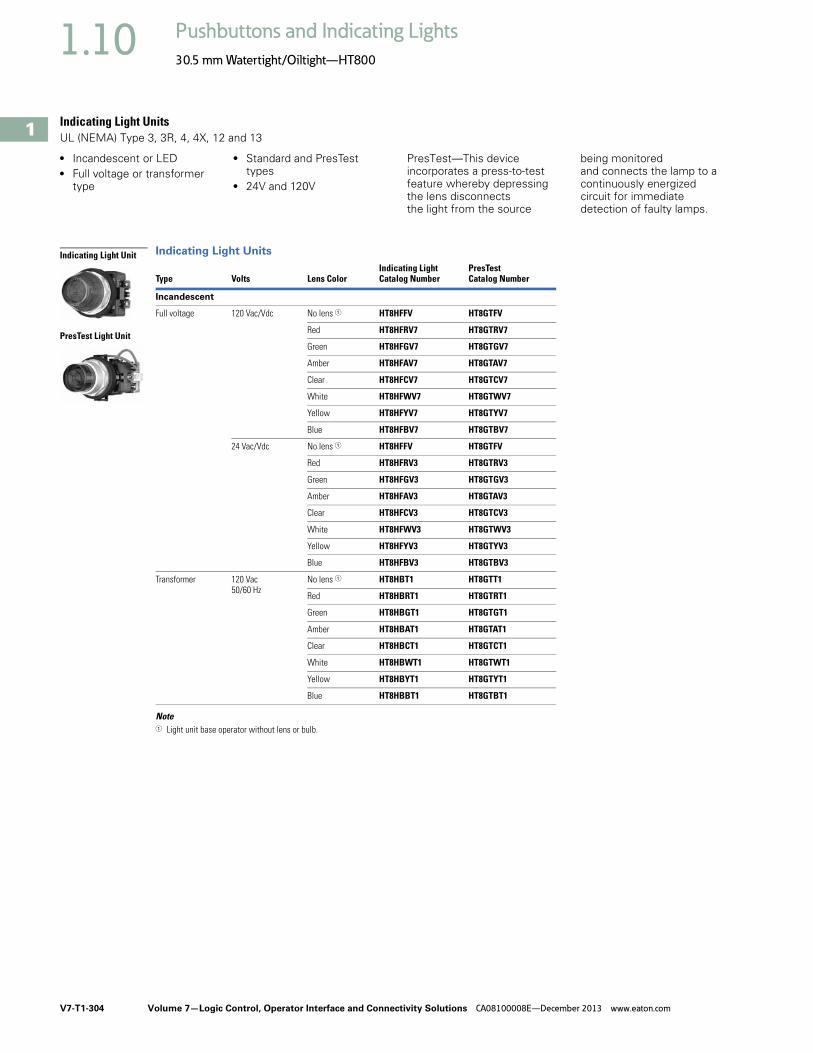
V7-T1-304 Volume 7—Logic Control, Operator Interface and Connectivity Solutions CA08100008E—December 2013 www.eaton.com
1
1
1
1
1
1
1
1
1
1
1
1
1
1
1
1
1
1
1
1
1
1
1
1
1
1
1
1
1
1
1.10 Pushbuttons and Indicating Lights
30.5 mm Watertight/Oiltight—HT800
Indicating Light UnitsUL (NEMA) Type 3, 3R, 4, 4X, 12 and 13
● Incandescent or LED● Full voltage or transformer
type
● Standard and PresTest types
● 24V and 120V
PresTest—This device incorporates a press-to-test feature whereby depressing the lens disconnects the light from the source
being monitored and connects the lamp to a continuously energized circuit for immediate detection of faulty lamps.
Indicating Light Units
Note1 Light unit base operator without lens or bulb.
Type Volts Lens ColorIndicating LightCatalog Number
PresTestCatalog Number
Incandescent
Full voltage 120 Vac/Vdc No lens 1 HT8HFFV HT8GTFV
Red HT8HFRV7 HT8GTRV7
Green HT8HFGV7 HT8GTGV7
Amber HT8HFAV7 HT8GTAV7
Clear HT8HFCV7 HT8GTCV7
White HT8HFWV7 HT8GTWV7
Yellow HT8HFYV7 HT8GTYV7
Blue HT8HFBV7 HT8GTBV7
24 Vac/Vdc No lens 1 HT8HFFV HT8GTFV
Red HT8HFRV3 HT8GTRV3
Green HT8HFGV3 HT8GTGV3
Amber HT8HFAV3 HT8GTAV3
Clear HT8HFCV3 HT8GTCV3
White HT8HFWV3 HT8GTWV3
Yellow HT8HFYV3 HT8GTYV3
Blue HT8HFBV3 HT8GTBV3
Transformer 120 Vac50/60 Hz
No lens 1 HT8HBT1 HT8GTT1
Red HT8HBRT1 HT8GTRT1
Green HT8HBGT1 HT8GTGT1
Amber HT8HBAT1 HT8GTAT1
Clear HT8HBCT1 HT8GTCT1
White HT8HBWT1 HT8GTWT1
Yellow HT8HBYT1 HT8GTYT1
Blue HT8HBBT1 HT8GTBT1
Indicating Light Unit
PresTest Light Unit

Volume 7—Logic Control, Operator Interface and Connectivity Solutions CA08100008E—December 2013 www.eaton.com V7-T1-305
1
1
1
1
1
1
1
1
1
1
1
1
1
1
1
1
1
1
1
1
1
1
1
1
1
1
1
1
1
1
1.10Pushbuttons and Indicating Lights
30.5 mm Watertight/Oiltight—HT800
UL (NEMA) Type 3, 3R, 4, 4X, 12 and 13
Indicating Light Units, continued
Note1 Light unit base operator without lens or bulb.
Type Volts Lens ColorIndicating LightCatalog Number
PresTestCatalog Number
LED
Full voltage 120 Vac/Vdc No lens 1 HT8HFFV HT8GTFV
Red HT8HFRF7 HT8GTRF7
Green HT8HFGF7 HT8GTGF7
Amber HT8HFAF7 HT8GTAF7
Clear HT8HFCF7 HT8GTCF7
White HT8HFWF7 HT8GTWF7
Yellow HT8HFYF7 HT8GTYF7
Blue HT8HFBF7 HT8GTBF7
24 Vac/Vdc No lens 1 HT8HFFV HT8GTFV
Red HT8HFRF3 HT8GTRF3
Green HT8HFGF3 HT8GTGF3
Amber HT8HFAF3 HT8GTAF3
Clear HT8HFCF3 HT8GTCF3
White HT8HFWF3 HT8GTWF3
Yellow HT8HFYF3 HT8GTYF3
Blue HT8HFBF3 HT8GTBF3
Transformer 120 Vac50/60 Hz
No lens 1 HT8HBT1 HT8GTT1
Red HT8HBRL1 HT8GTRL1
Green HT8HBGL1 HT8GTGL1
Amber HT8HBAL1 HT8GTAL1
Clear HT8HBCL1 HT8GTCL1
White HT8HBWL1 HT8GTWL1
Yellow HT8HBYL1 HT8GTYL1
Blue HT8HBBL1 HT8GTBL1
Indicating Light Unit
PresTest Light Unit

V7-T1-306 Volume 7—Logic Control, Operator Interface and Connectivity Solutions CA08100008E—December 2013 www.eaton.com
1
1
1
1
1
1
1
1
1
1
1
1
1
1
1
1
1
1
1
1
1
1
1
1
1
1
1
1
1
1
1.10 Pushbuttons and Indicating Lights
30.5 mm Watertight/Oiltight—HT800
Push-Pull UnitsUL (NEMA) Type 3, 3R, 4, 4X, 12 and 13
● 40 mm mushroom head● Two-position maintained● Non-illuminated
Two-Position Push-Pull, Maintained, Non-Illuminated
Note1 NCLB = normally closed late break.
Contact Type
Operator Position—Maintained
ButtonColor
Round Head Mushroom Head Button
Flat Head Mushroom Head Button
Out In Catalog Number Catalog Number
No contact — — Black HT8CBH HT8DBH
Red HT8CBR HT8DBR
Green HT8CBG HT8DBG
NO O X Black HT8CBHA HT8DBHA
Red HT8CBRA HT8DBRA
Green HT8CBGA HT8DBGA
NC X O Black HT8CBHB HT8DBHB
Red HT8CBRB HT8DBRB
Green HT8CBGB HT8DBGB
NO-NC OX
XO
Black HT8CBHAB HT8DBHAB
Red HT8CBRAB HT8DBRAB
Green HT8CBGAB HT8DBGAB
NCLB 1NC
XX
OO
Black HT8CBHD1B HT8DBHD1B
Red HT8CBRD1B HT8DBRD1B
Green HT8CBGD1B HT8DBGD1B
NCLB 1NCLB 1
XX
OO
Black HT8CBHD1D HT8DBHD1D
Red HT8CBRD1D HT8DBRD1D
Green HT8CBGD1D HT8DBGD1D
Round Head Two-Position Push-Pull Unit
Flat Head Two-Position Push-Pull Unit

Volume 7—Logic Control, Operator Interface and Connectivity Solutions CA08100008E—December 2013 www.eaton.com V7-T1-307
1
1
1
1
1
1
1
1
1
1
1
1
1
1
1
1
1
1
1
1
1
1
1
1
1
1
1
1
1
1
1.10Pushbuttons and Indicating Lights
30.5 mm Watertight/Oiltight—HT800
Illuminated Push-Pull UnitsUL (NEMA) Type 3, 3R, 4, 4X, 12 and 13
● Incandescent or LED● Full voltage or transformer type● 24V and 120V
Illuminated Push-Pull Units
Note: Complete illuminated push-pull switches will not fit in a standard 3 in deep enclosure.
Illuminated Push-Pull Units with Low Profile Light Units
Type VoltsLensColor
Operator OnlyCatalog Number
1NOCatalog Number
1NCCatalog Number
1NO-1NCCatalog Number
2NCLBCatalog Number
Incandescent Lamp
Full voltage 120 Vac/Vdc Red HT8FBRV7 HT8FBRAV7 HT8FBRBV7 HT8FBRABV7 HT8FBRD1DV7
Green HT8FBGV7 HT8FBGAV7 HT8FBGBV7 HT8FBGABV7 HT8FBGD1DV7
24 Vac/Vdc Red HT8FBRV3 HT8FBRAV3 HT8FBRBV3 HT8FBRABV3 HT8FBRD1DV3
Green HT8FBGV3 HT8FBGAV3 HT8FBGBV3 HT8FBGABV3 HT8FBGD1DV3
Transformer 120 Vac Red HT8FBRT1 HT8FBRAT1 HT8FBRBT1 HT8FBRABT1 HT8FBRD1DT1
Green HT8FBGT1 HT8FBGAT1 HT8FBGBT1 HT8FBGABT1 HT8FBGD1DT1
LED Lamp
Full voltage 120 Vac/Vdc Red HT8FBRF7 HT8FBRAF7 HT8FBRBF7 HT8FBRABF7 HT8FBRD1DF7
Green HT8FBGF7 HT8FBGAF7 HT8FBGBF7 HT8FBGABF7 HT8FBGD1DF7
24 Vac/Vdc Red HT8FBRF3 HT8FBRAF3 HT8FBRBF3 HT8FBRABF3 HT8FBRD1DF3
Green HT8FBGF3 HT8FBGAF3 HT8FBGBF3 HT8FBGABF3 HT8FBGD1DF3
Transformer 120 Vac Red HT8FBRL1 HT8FBRAL1 HT8FBRBL1 HT8FBRABL1 HT8FBRD1DL1
Green HT8FBGL1 HT8FBGAL1 HT8FBGBL1 HT8FBGABL1 HT8FBGD1DL1
Type Voltage Color FingersafeOperator OnlyCatalog Number
1NOCatalog Number
1NCCatalog Number
1NO-1NCCatalog Number
2NCLBCatalog Number
1NO-1NCLBCatalog Number
LED Lamp
Full voltage
120 Vac/Vdc
Red Yes HT8FBRFL7P HT8FBRAFL7P HT8FBRBFL7P HT8FBRABFL7P HT8FBRD1DFL7P HT8FBRD1BFL7P
Red No HT8FBRFL7 HT8FBRAFL7 HT8FBRBFL7 HT8FBRABFL7 HT8FBRD1DFL7 HT8FBRD1BFL7
24 Vac/Vdc
Red Yes HT8FBRFL3P HT8FBRAFL3P HT8FBRBFL3P HT8FBRABFL3P HT8FBRD1DFL3P HT8FBRD1BFL3P
Red No HT8FBRFL3 HT8FBRAFL3 HT8FBRBFL3 HT8FBRABFL3 HT8FBRD1DFL3 HT8FBRD1BFL3
Incandescent
Full voltage
120 Vac/Vdc
Red Yes HT8FBRVL7P HT8FBRAVL7P HT8FBRBVL7P HT8FBRABVL7P HT8FBRD1DVL7P HT8FBRD1BVL7P
Red No HT8FBRVL7 HT8FBRAVL7 HT8FBRBVL7 HT8FBRABVL7 HT8FBRD1DVL7 HT8FBRD1BVL7
24 Vac/Vdc
Red Yes HT8FBRVL3P HT8FBRAVL3P HT8FBRBVL3P HT8FBRABVL3P HT8FBRD1DVL3P HT8FBRD1BVL3P
Red No HT8FBRVL3 HT8FBRAVL3 HT8FBRBVL3 HT8FBRABVL3 HT8FBRD1DVL3 HT8FBRD1BVL3
Illuminated Push-Pull Unit

V7-T1-308 Volume 7—Logic Control, Operator Interface and Connectivity Solutions CA08100008E—December 2013 www.eaton.com
1
1
1
1
1
1
1
1
1
1
1
1
1
1
1
1
1
1
1
1
1
1
1
1
1
1
1
1
1
1
1.10 Pushbuttons and Indicating Lights
30.5 mm Watertight/Oiltight—HT800
Selector Switch UnitsUL (NEMA) Type 3, 3R, 4, 4X, 12 and 13
● Two-, three- and four-position● Non-illuminated
Two-Position Selector Switch Units, Non-Illuminated
Three-Position Selector Switch Units, Non-Illuminated
Notes1 X = closed circuit, O = open circuit.2 M = Maintained, S = Momentary.3 For OXO, NC contacts must be wired in series—see Three-Position Selector Switch table on Page V7-T1-310.
ContactType
Operator Position 1 Operating Mode 2 Standard Black Knob Catalog Number
Standard Black LeverCatalog Number
No contacts — — M M HT8JAH3A HT8JDH3A
S M HT8JKH3A HT8JLH3A
M S HT8JNH3A HT8JPH3A
1NO O X M M HT8JAH3AA5 HT8JDH3AA5
S M HT8JKH3AA5 HT8JLH3AA5
M S HT8JNH3AA5 HT8JPH3AA5
2NO XO
OX
M M HT8JAH3AAA5 HT8JDH3AAA5
S M HT8JKH3AAA5 HT8JLH3AAA5
M S HT8JNH3AAA5 HT8JPH3AAA5
2NO-2NC XOOX
OXXO
M M HT8JAH3AF1Q1 HT8JDH3AF1Q1
S M HT8JKH3AF1Q1 HT8JLH3AF1Q1
M S HT8JNH3AF1Q1 HT8JPH3AF1Q1
ContactType
Operator Position 1 Operating Mode 2 Standard Black Knob Catalog Number
Standard Black LeverCatalog Number
No contacts — — — M M M HT8JBH1D HT8JEH1D
S M M HT8JRH1D HT8JSH1D
M M S HT8JUH1D HT8JVH1D
S M S HT8JXH1D HT8JYH1D
2NO XO
OO
OX
M M M HT8JBH1DAA5 HT8JEH1DAA5
S M M HT8JRH1DAA5 HT8JSH1DAA5
M M S HT8JUH1DAA5 HT8JVH1DAA5
S M S HT8JXH1DAA5 HT8JYH1DAA5
2NO-2NC 3 XOO
OXO
OOX
M M M HT8JBH1DF1Q1 HT8JEH1DF1Q1
S M M HT8JRH1DF1Q1 HT8JSH1DF1Q1
M M S HT8JUH1DF1Q1 HT8JVH1DF1Q1
S M S HT8JXH1DF1Q1 HT8JYH1DF1Q1
2NO-2NC XOOX
OXOX
OXXO
M M M HT8JBH1DF1Q1 HT8JEH1DF1Q1
S M M HT8JRH1DF1Q1 HT8JSH1DF1Q1
M M S HT8JUH1DF1Q1 HT8JVH1DF1Q1
S M S HT8JXH1DF1Q1 HT8JYH1DF1Q1
Standard Knob Operator
Standard Lever Operator
Standard Knob Operator
Standard Lever Operator

Volume 7—Logic Control, Operator Interface and Connectivity Solutions CA08100008E—December 2013 www.eaton.com V7-T1-309
1
1
1
1
1
1
1
1
1
1
1
1
1
1
1
1
1
1
1
1
1
1
1
1
1
1
1
1
1
1
1.10Pushbuttons and Indicating Lights
30.5 mm Watertight/Oiltight—HT800
UL (NEMA) Type 3, 3R, 4, 4X, 12 and 13
Four-Position Selector Switch Units, Non-Illuminated
Notes1 X = closed circuit, O = open circuit.2 M = Maintained, S = Momentary.
ContactType
Operator Position 1 Operating Mode 2 Standard Black Knob Catalog Number
Standard Black LeverCatalog Number
No contacts — — — — M M M M HT8JCH8E HT8JFH8E
S M M M HT8LNH8E HT8LPH8E
M M M S HT8LRH8E HT8LSH8E
2NO-2NC XOOO
OXOO
OOXO
OOOX
M M M M HT8JCH8EF1Q1 HT8JFH8EF1Q1
S M M M HT8LNH8EF1Q1 HT8LPH8EF1Q1
M M M S HT8LRH8EF1Q1 HT8LSH8EF1Q1
Standard Knob Operator
Standard Lever Operator

V7-T1-310 Volume 7—Logic Control, Operator Interface and Connectivity Solutions CA08100008E—December 2013 www.eaton.com
1
1
1
1
1
1
1
1
1
1
1
1
1
1
1
1
1
1
1
1
1
1
1
1
1
1
1
1
1
1
1.10 Pushbuttons and Indicating Lights
30.5 mm Watertight/Oiltight—HT800
Selector Switch Contact Block Selection
For Two-, Three- and Four-Position Selector Switches
Two-Position Selector Switch (Cam Code 3A)
Three-Position Selector Switch (Cam Code 1D)
Four-Position Selector Switch (Cam Code 8E)
Operator Position
Left Right
X O
NOor
NC
O X
NCor
NO
Operator Position
Left Right
X O O
NO
—
O X O
NC NC
O O X —
NO
O X X
NC
—
X X O —
NC
Operator Position
Left Right
X O O O
NO
—
O X O O
NC
—
O O X O —
NO
O O O X —
NC
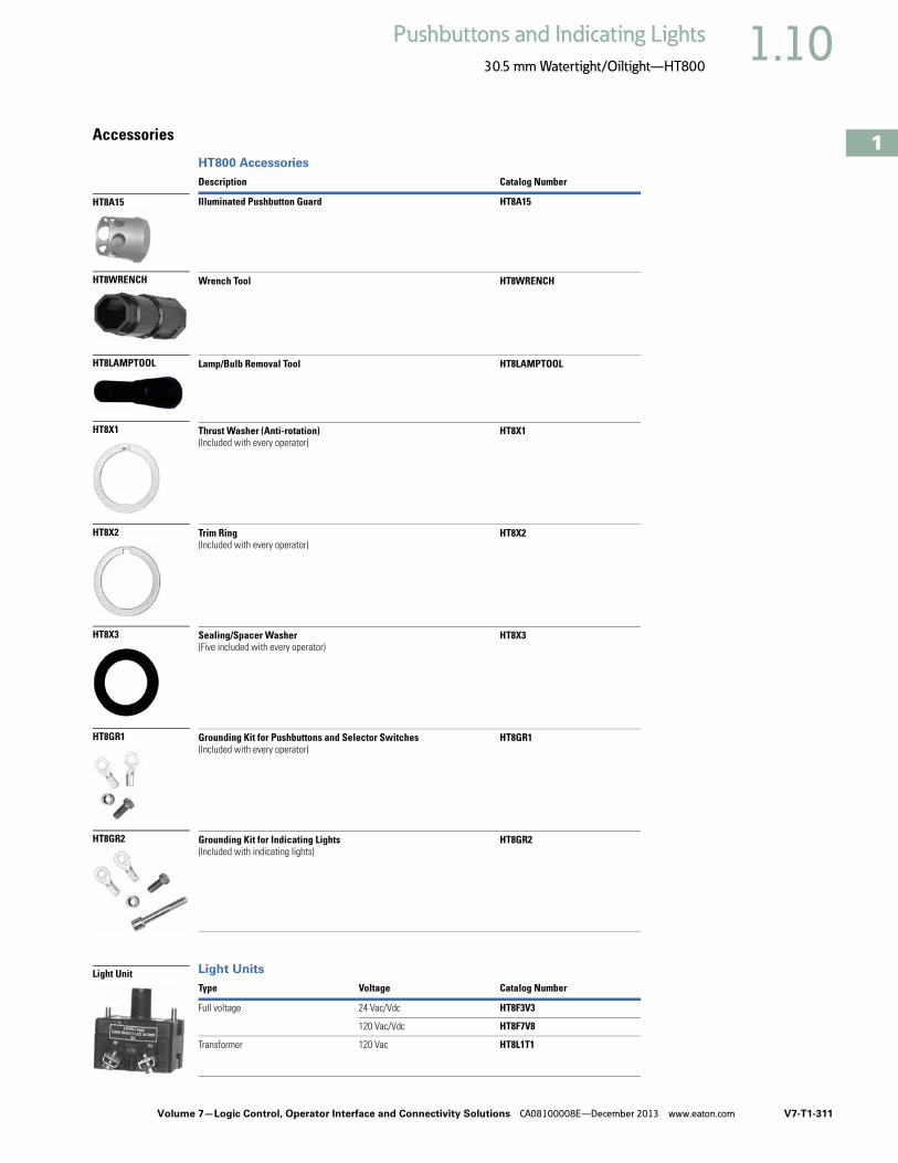
Volume 7—Logic Control, Operator Interface and Connectivity Solutions CA08100008E—December 2013 www.eaton.com V7-T1-311
1
1
1
1
1
1
1
1
1
1
1
1
1
1
1
1
1
1
1
1
1
1
1
1
1
1
1
1
1
1
1.10Pushbuttons and Indicating Lights
30.5 mm Watertight/Oiltight—HT800
Accessories
HT800 Accessories
Light Units
Description Catalog Number
Illuminated Pushbutton Guard HT8A15
Wrench Tool HT8WRENCH
Lamp/Bulb Removal Tool HT8LAMPTOOL
Thrust Washer (Anti-rotation)(Included with every operator)
HT8X1
Trim Ring(Included with every operator)
HT8X2
Sealing/Spacer Washer(Five included with every operator)
HT8X3
Grounding Kit for Pushbuttons and Selector Switches(Included with every operator)
HT8GR1
Grounding Kit for Indicating Lights(Included with indicating lights)
HT8GR2
Type Voltage Catalog Number
Full voltage 24 Vac/Vdc HT8F3V3
120 Vac/Vdc HT8F7V8
Transformer 120 Vac HT8L1T1
HT8A15
HT8WRENCH
HT8LAMPTOOL
HT8X3
HT8GR2
HT8GR1
HT8X2
HT8X1
Light Unit

V7-T1-312 Volume 7—Logic Control, Operator Interface and Connectivity Solutions CA08100008E—December 2013 www.eaton.com
1
1
1
1
1
1
1
1
1
1
1
1
1
1
1
1
1
1
1
1
1
1
1
1
1
1
1
1
1
1
1.10 Pushbuttons and Indicating Lights
30.5 mm Watertight/Oiltight—HT800
OptionsLegend Plates 1
For Pushbutton Operators and Indicating Lights
For Selector Switch Operators
For Push-Pull Units Blank Plastic Legend Plates—Square
Notes1 For dimensions, see Page V7-T1-320.2 3/32 in high lettering.3 1/8 in high lettering.
LegendColor ofField
StandardCatalog Number
Jumbo Catalog Number Legend
Color ofField
StandardCatalog Number
Jumbo Catalog Number
Letters on Legend Plates Below are 3/16 in High
CLAMP Black HT8SP90 HT8LP90 OFF Red HT8SP24 HT8LP24
CLOSE HT8SP73 HT8LP73 ON Black HT8SP25 HT8LP25
DOWN HT8SP74 HT8LP74 OPEN HT8SP26 HT8LP26
EMERG. STOP HT8SP13 HT8LP13 OUT HT8SP27 HT8LP27
FAST HT8SP75 HT8LP75 POWER ON HT8SP80 HT8LP80
FASTER HT8SP87 HT8LP87 RAISE HT8SP28 HT8LP28
FEEDER ON HT8SP94 HT8LP94 READY HT8SP86 HT8LP86
FEEDER OFF HT8SP95 HT8LP95 RESET HT8SP29 HT8LP29
FORWARD HT8SP15 HT8LP15 REVERSE HT8SP30 HT8LP30
HIGH HT8SP16 HT8LP16 RUN HT8SP31 HT8LP31
IN HT8SP17 HT8LP17 SAFE HT8SP85 HT8LP85
INCH HT8SP18 HT8LP18 SLOW HT8SP32 HT8LP32
JOG HT8SP19 HT8LP19 SLOWER HT8SP88 HT8LP88
JOG FOR. HT8SP20 HT8LP20 START HT8SP33 HT8LP33
JOG REV. HT8SP21 HT8LP21 STOP Red HT8SP34 HT8LP34
LOW HT8SP22 HT8LP22 TEST Black HT8SP83 HT8LP83
LOWER HT8SP23 HT8LP23 TRANSFER HT8SP93 HT8LP93
LUBE-FAIL HT8SP92 HT8LP92 TRIP HT8SP84 HT8LP84
MOTOR RUN HT8SP81 HT8LP81 UNCLAMP HT8SP91 HT8LP91
MOTOR STOP HT8SP82 HT8LP82 UP HT8SP35 HT8LP35
LegendColor ofField
StandardCatalog Number
Jumbo Catalog Number Legend
Color ofField
StandardCatalog Number
Jumbo Catalog Number
Two-Position—3/16 in High Lettering Three-Position—3/16 in High Lettering
FOR. REV. Black HT8SP38 HT8LP38 AUTO OFF HAND Black HT8SP49 HT8LP49
HAND AUTO HT8SP39 HT8LP39 FOR. OFF REV. HT8SP50 HT8LP50
HIGH LOW HT8SP40 HT8LP40 FOR. SAFE REV. HT8SP69 HT8LP69
JOG RUN HT8SP41 HT8LP41 HAND OFF AUTO HT8SP51 HT8LP51
MAN. AUTO HT8SP67 HT8LP67 MAN. OFF AUTO HT8SP68 HT8LP68
OFF ON HT8SP42 HT8LP42 OPEN OFF CLOSE HT8SP53 HT8LP53
OPEN CLOSE HT8SP43 HT8LP43 RUN SAFE JOG HT8SP70 HT8LP70
RUN JOG HT8SP44 HT8LP44 UP OFF DOWN HT8SP54 HT8LP54
SAFE RUN HT8SP45 HT8LP45 ON STOP SAFE HT8SP71 HT8LP71
START JOG HT8SP46 HT8LP46
START STOP HT8SP47 HT8LP47
UP DOWN HT8SP48 HT8LP48
Standard
Jumbo
Standard
Jumbo
LegendColor ofField
Standard 2Catalog Number
Jumbo 3Catalog Number
ON/OFF Black HT8PP5 HT8R5
OPEN/CLOSE HT8PP8 HT8R8
UP/DOWN HT8PP11 HT8R11
LegendColor ofField
StandardCatalog Number
JumboCatalog Number
Black White/Silver HT8SP76 HT8LP76
White Red/ Black HT8SP77 HT8LP77
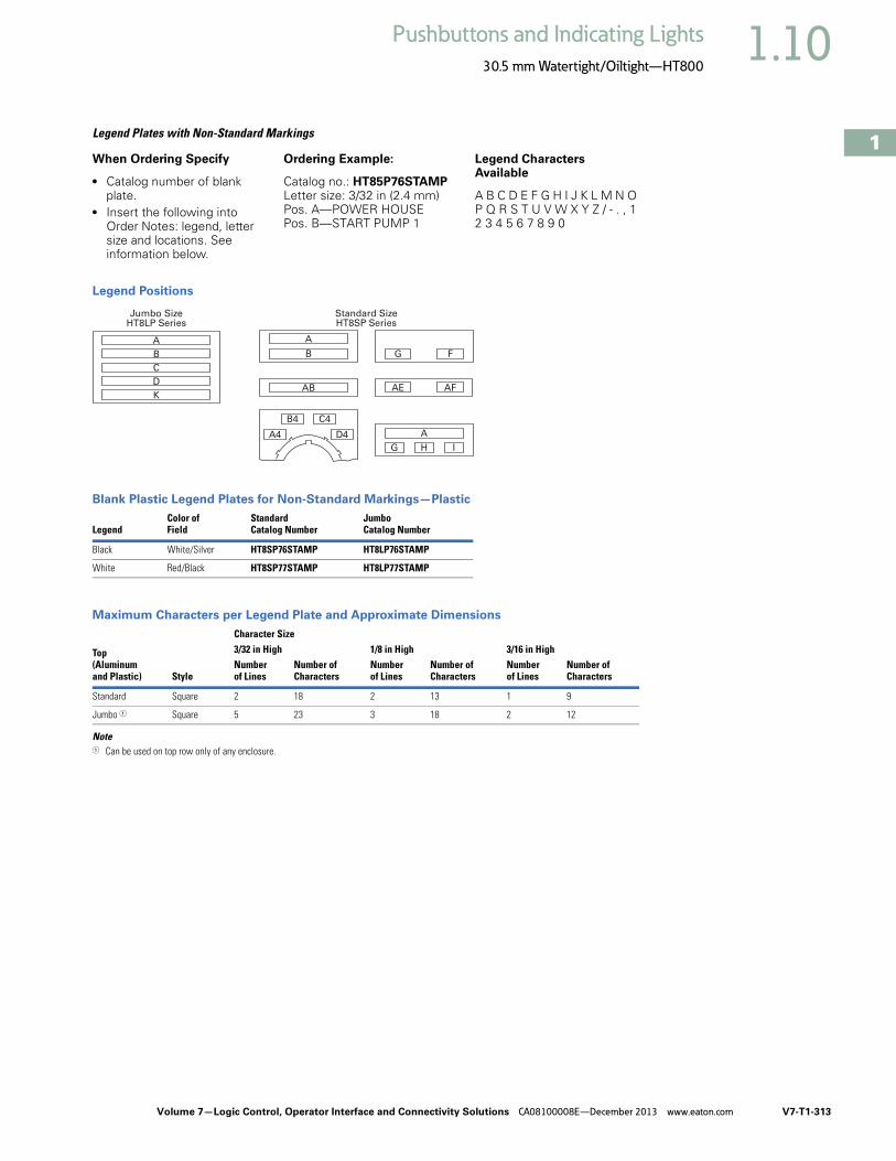
Volume 7—Logic Control, Operator Interface and Connectivity Solutions CA08100008E—December 2013 www.eaton.com V7-T1-313
1
1
1
1
1
1
1
1
1
1
1
1
1
1
1
1
1
1
1
1
1
1
1
1
1
1
1
1
1
1
1.10Pushbuttons and Indicating Lights
30.5 mm Watertight/Oiltight—HT800
Legend Plates with Non-Standard Markings
When Ordering Specify
● Catalog number of blank plate.
● Insert the following into Order Notes: legend, letter size and locations. See information below.
Ordering Example:
Catalog no.: HT85P76STAMPLetter size: 3/32 in (2.4 mm)Pos. A—POWER HOUSEPos. B—START PUMP 1
Legend Characters Available
A B C D E F G H I J K L M N O P Q R S T U V W X Y Z / - . , 1 2 3 4 5 6 7 8 9 0
Legend Positions
Blank Plastic Legend Plates for Non-Standard Markings—Plastic
Maximum Characters per Legend Plate and Approximate Dimensions
Note1 Can be used on top row only of any enclosure.
LegendColor ofField
StandardCatalog Number
JumboCatalog Number
Black White/Silver HT8SP76STAMP HT8LP76STAMP
White Red/Black HT8SP77STAMP HT8LP77STAMP
Top(Aluminumand Plastic) Style
Character Size3/32 in High 1/8 in High 3/16 in HighNumberof Lines
Number ofCharacters
Numberof Lines
Number ofCharacters
Numberof Lines
Number ofCharacters
Standard Square 2 18 2 13 1 9
Jumbo 1 Square 5 23 3 18 2 12
Jumbo SizeHT8LP Series
A
C
K
D
B
Standard SizeHT8SP Series
AB
B
A
G F
AE
G H
A
I
AF
D4
C4B4
A4

V7-T1-314 Volume 7—Logic Control, Operator Interface and Connectivity Solutions CA08100008E—December 2013 www.eaton.com
1
1
1
1
1
1
1
1
1
1
1
1
1
1
1
1
1
1
1
1
1
1
1
1
1
1
1
1
1
1
1.10 Pushbuttons and Indicating Lights
30.5 mm Watertight/Oiltight—HT800
Contact Blocks
Contact Blocks 12
Contact Block Location (Viewed from Rear) Suffix Codes 34
Notes1 See Page V7-T1-316 for contact block electrical ratings.2 Maximum of four contact blocks per side or a total of eight contact blocks recommended. 3 Maximum of two contact blocks per side or a total of four contact blocks recommended. 4 Standard contact blocks without fingerproof protection.
Description/FunctionContactType
Without GuardCatalog Number
FingerproofCatalog Number
Standard normally open contact NO HT8A HT8AP
Standard normally closed contact NC HT8B HT8BP
Normally open early make contact will make circuit before standard NO contact. DC ratings do not apply.
NOEM HT8C HT8CP
Normally closed late break contact will open after standard NC contact. DC ratings do not apply.
NCLB HT8D HT8DP
Logic level, low voltage NO contact. Gold plated contacts.
NO HT8E HT8EP
Left Side Right Side
A = NO A5 = NO
A2 = 2NO A6 = 2NO
B1 = NC B = NC
B2 = 2NC B6 = 2NC
C = NOEM C5 = NOEM
C2 = 2 NOEM C6 = 2 NOEM
D1 = NCLB D = NCLB
D2 = 2 NCLB D6 = 2 NCLB
E1 = NOEM-NCLB E5 = NOEM-NCLB
F1 = NO and NC Q1 = NO and NC
F4 = 1NO-1NC
NO Contact Block
NC Contact Block

Volume 7—Logic Control, Operator Interface and Connectivity Solutions CA08100008E—December 2013 www.eaton.com V7-T1-315
1
1
1
1
1
1
1
1
1
1
1
1
1
1
1
1
1
1
1
1
1
1
1
1
1
1
1
1
1
1
1.10Pushbuttons and Indicating Lights
30.5 mm Watertight/Oiltight—HT800
Replacement Parts
Replacement Bulbs and LEDs
Replacement Lenses
Voltage Color Catalog Number
Incandescent
6V — HT8BULBV1
24V — HT8BULBV3
120V — HT8BULBV7
LED
6–12V(For use with transformers with 6V secondary winding)
Red HT8LEDRF1
Green HT8LEDGF1
Amber/orange HT8LEDAF1
White/clear HT8LEDWF1
Yellow HT8LEDYF1
Blue HT8LEDBF1
24V Red HT8LEDRF3
Green HT8LEDGF3
Amber/orange HT8LEDAF3
White/clear HT8LEDWF3
Yellow HT8LEDYF3
Blue HT8LEDBF3
120V Red HT8LEDRF7
Green HT8LEDGF7
Amber/orange HT8LEDAF7
White/clear HT8LEDWF7
Yellow HT8LEDYF7
Blue HT8LEDBF7
ColorIndicating LightsCatalog Number
PresTest LightsIlluminated PushbuttonsCatalog Number
Amber HT8LA HT8BA
Blue HT8LB HT8BB
Clear HT8LC HT8BC
Green HT8LG HT8BG
Red HT8LR HT8BR
White HT8LW HT8BW
Yellow HT8LY HT8BY
Incandescent Bulb
LED Bulb

V7-T1-316 Volume 7—Logic Control, Operator Interface and Connectivity Solutions CA08100008E—December 2013 www.eaton.com
1
1
1
1
1
1
1
1
1
1
1
1
1
1
1
1
1
1
1
1
1
1
1
1
1
1
1
1
1
1
1.10 Pushbuttons and Indicating Lights
30.5 mm Watertight/Oiltight—HT800
Technical Data and Specifications
HT800—Specifications
Electrical Ratings—HT800 Standard Contact Blocks, UL Rating
UL A600 and P600 Ratings
Notes1 Heavy-duty.2 Standard duty.3 DC ratings do not apply to NOEM (Normally Open Early Make) and NCLB (Normal Closed Late Break) contact blocks HT8C and HT8D.4 Maximum make or break volt-amperes at 300V or less.
Description Specification
Mechanical Ratings
Frequency of operation
Pushbuttons 6,000 operations per hour
Selector switches 3,000 operations per hour
Push-pull operators 3,000 operations per hour
Mechanical endurance/life
Pushbuttons 10 x 106 operations 6K ops/hr with 6 NO on left and 6 NC on right
Selector switches 250 x 103 operations 3K ops/hr with 2 NO on left and 2 NC on right
Push-pull operators 250 x 103 operations 3K ops/hr with 6 NO on left and 6 NC on right
Climatic Conditions
Operating temperature 10° to 140°F (–12° to 60°C)
Storage temperature –40° to 176°F (–40° to 80°C)
Altitude 6,562 ft (2,000m)
Humidity 95% RH at 60°C
Terminals
Contact blocks #6-32 posidrive saddle clamp type, 1 x 16 AWG to 2 x 14 AWG, 12 in-lbs max.
Light units #6-32 posidrive saddle clamp type, 1 x 22 AWG to 2 x 14 AWG, 7 in-lbs max.
Electrical Ratings
Standard contact blocks UL (NEMA) rating See table below.
Logic level contact block power rating 5V 1 mA (minimum)28V 500 mA (maximum)
Description/FunctionContactType AC DC Catalog Number
Standard normally open contact NO A600 1 P600 2 HT8A
Standard normally closed contact NC A600 1 P600 2 HT8B
Normally open early make contact will make circuit before standard NO contact. DC ratings do not apply.
NOEM A600 1 — HT8C
Normally closed late break contact will open after standard NC contact. DC ratings do not apply.
NCLB A600 1 — HT8D
Logic level, low voltage NO contact. Gold plated contacts. NO 5V 1 mA (minimum)28V 500 mA (maximum)
HT8E
Description50 Vac or 60 Hz Vdc 3
120 240 480 600 125 250 600
Make and emerg. interrupting capacity (amp) 60 30 15 12 1.1 0.55 0.2
Normal load break (amp) 6 3 1.5 1.2 1.1 0.55 0.2
Thermal current (amp) 10 10 10 10 5 5 5
Voltamperes:
Make and emerg. interrupting capacity 7200 7200 7200 7200 138 4 138 4 138 4
Normal load break 720 720 720 720 138 138 138

Volume 7—Logic Control, Operator Interface and Connectivity Solutions CA08100008E—December 2013 www.eaton.com V7-T1-317
1
1
1
1
1
1
1
1
1
1
1
1
1
1
1
1
1
1
1
1
1
1
1
1
1
1
1
1
1
1
1.10Pushbuttons and Indicating Lights
30.5 mm Watertight/Oiltight—HT800
DimensionsApproximate Dimensions in Inches (mm)
Momentary Pushbuttons—Non-IlluminatedBack, side and bottom views of pushbutton operator with attached contact blocks.
Illuminated PushbuttonsBack, side and bottom views of pushbutton operator with attached contact blocks.
Note1 Recommended maximum of four tandem stacks of contact blocks behind operator. At users’ discretion, two additional tandem stacks may be added.
4.60 (116.8)
Side View
Back View
Bottom View
1.40(35.6)
PanelStacking Screw Torque:12 in-lbs Max.
#6-32 Posi-driveSaddle Clamp Type
1x16 AWG to 2 x14 AWGTerminal Torque:
12 in-lbs Max.Copper Wire Only
3.70 (94.0)
2.90 (73.7) 0.90 (22.9)Extended
0.75 (19.1)Flush
2.00 (50.8)
1.00(25.4)
2.00 (50.8)
Recommended 4 Stacks(8 Contact Blocks Total)
Optional2 Stacks
1
PanelLight Unit #6-32 Posi-driveSaddle Clamp Type
1x16 AWG to 2x14 AWGTerminal Torque:
7 in-lbs Max.Copper Wire Only
Contact Block#6-32 Posi-drive
Saddle Clamp Type1x16 AWG to 2 x14 AWG
Terminal Torque:12 in-lbs Max.
Copper Wire Only
5.15 (130.8)
1.40(35.6)
Side View
4.35 (110.5)
3.55 (90.2)1.50
(38.1)2.75 (69.9)
Back View
1.00(25.4)
2.00 (50.8)
Bottom View
Recommended 4 Stacks(8 Contact Blocks Total)
Optional2 Stacks
Stacking Screw Torque:12 in-lbs Max.
1

V7-T1-318 Volume 7—Logic Control, Operator Interface and Connectivity Solutions CA08100008E—December 2013 www.eaton.com
1
1
1
1
1
1
1
1
1
1
1
1
1
1
1
1
1
1
1
1
1
1
1
1
1
1
1
1
1
1
1.10 Pushbuttons and Indicating Lights
30.5 mm Watertight/Oiltight—HT800
Approximate Dimensions in Inches (mm)
Mushroom Head Pushbuttons and Round Head MRH Push-Pull OperatorsBack, side and bottom views of mushroom head operator with attached contact blocks.
Illuminated and Non-Illuminated Flat Head MRH Push-Pull OperatorsBack, side and bottom views of push-pull operator with attached contact blocks.
Notes1 Recommended maximum of four tandem stacks of contact blocks behind operator. At users’ discretion, two additional tandem stacks may be added.2 Contact blocks mount directly to operator adaptor in non-illuminated version.
4.60 (116.8)
Side View
1.40(35.6)
PanelStacking Screw Torque:12 in-lbs Max.
#6-32 Posi-driveSaddle Clamp Type
1x16 AWG to 2x14 AWGTerminal Torque:
12 in-lbs Max.Copper Wire Only
3.70 (94.0)
2.90 (73.7)
1.50(38.1)
2.00 (50.8)
Back View
1.00(25.4)
2.00 (50.8)
Bottom View
Recommended 4 Stacks(8 Contact Blocks Total)
Optional2 Stacks
1
4.35 (110.5)
Side View
Back View
Bottom View
1.40(35.6)
Panel
Stacking Screw Torque:12 in-lbs Max.
Contact Block#6-32 Posi-drive
Saddle Clamp Type1x16 AWG to 2 x14 AWG
Terminal Torque:12 in-lbs Max.
Copper Wire Only
Light Unit#6-32 Posi-drive
Saddle Clamp Type1x22 AWG to 2 x14 AWG
Terminal Torque:7 in-lbs Max.
Copper Wire Only
3.55 (90.2)
2.75 (69.9)
1.30(33.0)
1.00(25.4)
2.00 (50.8)
Recommended 4 Stacks(8 Contact Blocks Total)
Optional2 Stacks
5.15 (130.8)
1 2

Volume 7—Logic Control, Operator Interface and Connectivity Solutions CA08100008E—December 2013 www.eaton.com V7-T1-319
1
1
1
1
1
1
1
1
1
1
1
1
1
1
1
1
1
1
1
1
1
1
1
1
1
1
1
1
1
1
1.10Pushbuttons and Indicating Lights
30.5 mm Watertight/Oiltight—HT800
Approximate Dimensions in Inches (mm)
Indicating LightsBack, side and bottom views of indicating light operator with attached contact blocks.
Selector SwitchesBack, side and bottom views of selector switch operator with attached contact blocks.
Side View
Back View
Bottom View
1.30(33.0)
Panel
Stacking Screw Torque:12 in-lbs Max.
#6-32 Posi-driveSaddle Clamp Type
1x22 AWG to 2x14 AWGTerminal Torque:
7 in-lbs Max.Copper Wire Only
1.67(42.4)
Light UnitAssembly
1.26(32.0)
1.68(42.7)
Side View
Back View
Bottom View
1.40(35.6)
PanelStacking Screw Torque:12 in-lbs Max.
#6-32 Posi-driveSaddle Clamp Type
1x16 AWG to 2x14 AWGTerminal Torque:
12 in-lbs Max.Copper Wire Only
2.90 (73.7)1.20
(38.1)2.00 (50.8)
1.00(25.4)
2.00 (50.8)
Recommended2 Stacks
(4 Contact Blocks Total)

V7-T1-320 Volume 7—Logic Control, Operator Interface and Connectivity Solutions CA08100008E—December 2013 www.eaton.com
1
1
1
1
1
1
1
1
1
1
1
1
1
1
1
1
1
1
1
1
1
1
1
1
1
1
1
1
1
1
1.10 Pushbuttons and Indicating Lights
30.5 mm Watertight/Oiltight—HT800
Approximate Dimensions in Inches (mm)
Mounting Matrix and Minimum Panel Spacing Requirements Legend Plates
0.68(17.3)
Optional NotchLocations
1.20 (30.5)Diameter
2.50(63.5)
2.50 (63.5)
0.18 (4.6)
2.19
(55.6)
Jumbo
1.77
(45)
Standard
2.19
(55.6)1.77
(45)
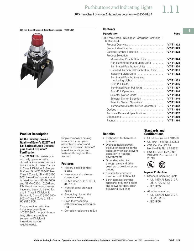
Volume 7—Logic Control, Operator Interface and Connectivity Solutions CA08100008E—December 2013 www.eaton.com V7-T1-321
1
1
1
1
1
1
1
1
1
1
1
1
1
1
1
1
1
1
1
1
1
1
1
1
1
1
1
1
1
1
1.11Pushbuttons and Indicating Lights
30.5 mm Class I Division 2 Hazardous Locations—10250T/E34
30.5 mm Class I Division 2 Hazardous Locations—10250T/E34 ContentsDescription Page
30.5 mm Class I Division 2 Hazardous Locations—10250T/E34
Product Overview . . . . . . . . . . . . . . . . . . . . . . . V7-T1-322
Product Identification . . . . . . . . . . . . . . . . . . . . V7-T1-323
Catalog Number Selection . . . . . . . . . . . . . . . . V7-T1-323
Product SelectionMomentary Pushbutton Units . . . . . . . . . . . V7-T1-324
Non-Illuminated Pushbutton Units . . . . . . . V7-T1-328
Illuminated Pushbutton Units . . . . . . . . . . . V7-T1-330
Guarded Illuminated Pushbutton Units . . . . V7-T1-331
Indicating Light Units . . . . . . . . . . . . . . . . . V7-T1-332
Illuminated Pushbuttons and Indicating Lights . . . . . . . . . . . . . . . . . . . . V7-T1-333
Push-Pull Units . . . . . . . . . . . . . . . . . . . . . . V7-T1-335
Illuminated Push-Pull Units . . . . . . . . . . . . . V7-T1-337
Push-Pull Operators . . . . . . . . . . . . . . . . . . . V7-T1-340
Selector Switch Units . . . . . . . . . . . . . . . . . V7-T1-344
Selector Switch Selection . . . . . . . . . . . . . . V7-T1-346
Selector Switch Operators . . . . . . . . . . . . . V7-T1-349
Illuminated Selector Switch Operators . . . . V7-T1-352
Options . . . . . . . . . . . . . . . . . . . . . . . . . . . . . . . V7-T1-354
Technical Data and Specifications . . . . . . . . . . V7-T1-357
Dimensions . . . . . . . . . . . . . . . . . . . . . . . . . . . V7-T1-359
Ratings . . . . . . . . . . . . . . . . . . . . . . . . . . . . . . . V7-T1-360
Product DescriptionAll the Industry-Proven Quality of Eaton’s 10250T and E34 Series of Logic Devices, plus Class I Division 2 CertificationThe 10250T1H consists of a normally open-normally closed factory sealed contact block that is UL Listed for use in Class I, Division 2, Groups B, C and D (NEC 500–503)—Class I, Zone 2, IIB + H2 (NEC 505) hazardous locations and is rated for both NEMA A600 and NEMA Q300. 10250T and E34 illuminated components have also been UL Listed for use in Class I, Division 2, Groups B, C and D (NEC 500–503)—Class I, Zone 2, IIB + H2 (NEC 505).
This, combined with the industry-proven Eaton 10250T 30.5 mm pushbutton line, offers a complete solution to Division 2 hazardous location requirements.
Single composite catalog numbers for complete assembled stations and operators for use in Division 2 hazardous locations are featured throughout this section.
Features● Factory sealed contact
blocks● Heavy-duty zinc die cast
construction● NEMA rated 1, 2, 3, 3R, 4,
4X, 12, 13● Front-of-panel drainage
holes● Grounding nibs on the
operator casing● Solid thermosetting
cathodic epoxy coating on E34
● Corrosion resistance in E34
Benefits● Pushbutton for hazardous
locations● Drainage holes prevent
buildup of liquid inside the operator which can prevent operation in freezing environments
● Grounding nibs bite through paint and other coatings to provide secure ground
● Suitable for corrosive environments (E34 only)
● Earth terminal provides additional grounding point and allows for daisy chain grounding (E34 line)
Standards and Certifications● UL 508—File No. E131568● UL 1604—File No. E10323● CSA Certified C22.2
No.14—File No. LR 68551● CSA Certified C22.2 No.
213-M1987—File No. LR 20713
Ingress Protection ● Standard indicating lights
● UL (NEMA) Type 3, 3R, 3S, 4, 4X, 12, 13
● IEC IP65
● All other operators● UL (NEMA) Type 3, 3R,
4, 4X, 12, 13● IEC IP65

V7-T1-322 Volume 7—Logic Control, Operator Interface and Connectivity Solutions CA08100008E—December 2013 www.eaton.com
1
1
1
1
1
1
1
1
1
1
1
1
1
1
1
1
1
1
1
1
1
1
1
1
1
1
1
1
1
1
1.11 Pushbuttons and Indicating Lights
30.5 mm Class I Division 2 Hazardous Locations—10250T/E34
Product OverviewOperatorThe 30.5 mm 10250T pushbutton line features a zinc die cast construction with chrome-plated housing and mounting nut.
Eaton’s E34 Series 30.5 mm pushbutton line features the same rugged die cast construction of our 10250T line with an additional two-layer 100% solid thermosetting cathodic epoxy coating. This coating provides a flat black smooth, consistent, corrosion resistant surface that has passed a demanding 600 hour salt spray test. (The industry standard for this 4X test requires only 200 hours.)
Ultraviolet LightE34 epoxy coating is not recommended for use in applications where exposure to ultraviolet light exists—use NEMA 4X 10250T operators.
RatingsOur Class I Division 2 line of pushbuttons are UL Listed (NEMA type) 1, 2, 3, 3R, 4, 4X, 12 and 13. Our Class I Division 2 E34 line meets IEC 947-1 IP66 standards and the cathodic coating meets FDA 3A sanitary chemical resistance requirements. For a complete listing of all applicable ratings see Pages V7-T1-357 toV7-T1-358.
10250T Grounding Nibs10250T line operators have “grounding nibs”—four metal points on the operator casting designed to bite through most paints and other coatings on metal panels to enhance the grounding connection when the operator is securely tightened.
10250T Grounding Nibs
E34 Grounding NibsE34 line of operators is equipped with a ground screw terminal as part of its die cast construction. This earthing terminal provides an easily accessible point for grounding operators when used in a painted or nonmetallic enclosure and eliminates the need for extra kits when daisy chain grounding is required.
E34 Grounding Nibs
Nib
Earth Terminal
Diaphragm Seal with Drainage Holes
Liquid DrainageEaton’s pushbutton operators offer front of panel drainage via holes in the operator bushing. Hidden from view by the mounting nut, these holes prevent buildup of liquid inside the operator, which can prevent operation in freezing environments. The holes also provide a route for escaping liquid in high pressure washdowns, effectively relieving pressure from the internal diaphragm seal, ensuring reliable sealing in applications even beyond NEMA 4.
Diaphragm Seal
Foam NeoprenePanel Sealing Gasket
Drainage Hole
Drainage Hole
FlexibleDiaphragm
StainlessSteel
OperatingSpring
Mounting Nut
ColorfastMoldedButton

Volume 7—Logic Control, Operator Interface and Connectivity Solutions CA08100008E—December 2013 www.eaton.com V7-T1-323
1
1
1
1
1
1
1
1
1
1
1
1
1
1
1
1
1
1
1
1
1
1
1
1
1
1
1
1
1
1
1.11Pushbuttons and Indicating Lights
30.5 mm Class I Division 2 Hazardous Locations—10250T/E34
Product Identification
30.5 mm Class I Division 2 Hazardous Locations
Catalog Number SelectionCatalog Number Selection is for illustrative purposes only and not to be used to create new catalog numbers.
Non-Illuminated Assembled Operators
ACC/SS TypeBlank = None
J = JMB push-pullB = Booted-FL/EXTG = Guarded-FLK = Knob-SSL = Lever-SSA = Lever W/IP-SSC = Coin-SS
Keyed-SS— —
Cam1237
Button ColorB = BlackR = RedG = GreenY = Yellow
W = WhiteL = Blue
N = OrangeE = Red EMERG. STOPT = Keyed-SS
Key Removal1 = RT only2 = LT only3 = RT and LT4 = CT only5 = RT and CT6 = LT and CT7 = All
Operator and Contact Block706 = Flush 1NO-1NC707 = Flush 2NO-2NC708 = Extended 1NO-1NC709 = Extended 2NO-2NC710 = Mushroom 1NO-1NC711 = Mushroom 2NO-2NC712 = JMB mushroom 1NO-1NC713 = JMB mushroom 2NO-2NC714 = 2P MT push-pull 1NO-1NC715 = 2P MT push-pull 2NO-2NC716 = 3P MT push-mom pull 1NO-1NC717 = 3P MT push-mom pull 2NO-2NC718 = 3P mom push-pull 1NO-1NC721 = 3P mom push-pull 2NO-2NC
722 = 2P SS MT XO,OX-CAM1723 = 2P SS MT XO,OX,XO,OX-CAM1724 = 2P SS SPR-R XO,OX-CAM1725 = 2P SS SPR-R XO,OX,XO,OX-CAM1726 = 3P SS MT XOO,OOX-CAM3727 = 3P SS MT XOO,OXO,OOX-CAM3728 = 3P SS SPR-L XOO,OOX-CAM3729 = 3P SS SPR-L XOO,OXO,OOX-CAM3730 = 3P SS SPR-L&R XOO,OOX-CAM3731 = 3P SS SPR-L&R XOO,OXO,OOX-CAM3732 = 3P SS SPR-R XOO,OOX-CAM3733 = 3P SS SPR-R XOO,OXO,OOX-CAM3743 = 4P SS MT XOOO,OXOO,OOXO,OOOX-CAM7
Operator Type10250T = Heavy-duty oiltightE34EX = Corrosion resistant oiltight
10250T 718 E J

V7-T1-324 Volume 7—Logic Control, Operator Interface and Connectivity Solutions CA08100008E—December 2013 www.eaton.com
1
1
1
1
1
1
1
1
1
1
1
1
1
1
1
1
1
1
1
1
1
1
1
1
1
1
1
1
1
1
1.11 Pushbuttons and Indicating Lights
30.5 mm Class I Division 2 Hazardous Locations—10250T/E34
Product SelectionMomentary Pushbutton UnitsUL (NEMA) Type 3, 3R, 4, 4X, 12, 13, NEC Class I Division 2, Groups B, C and D
Non-Illuminated Flush and Extended Pushbuttons
Color Selection
NotesUse NEMA 4X 10250T operators where exposed to ultraviolet light.1 To order different color guarded button, simply substitute the underlined character in catalog number with
appropriate suffix code from Color Selection table above. Example: 10250T710Y.2 Blue not available on jumbo mushroom pushbutton.3 Orange is only available on flush or extended pushbuttons.4 Red with EMERG. STOP engraved on button head for jumbo mushroom pushbutton only.
Contact TypeButton Color 1
Flush Button Extended Button10250TCatalog Number
E34Catalog Number
10250TCatalog Number
E34Catalog Number
1NO-1NC Black 10250T706B E34EX706B 10250T708B E34EX708B
Red 10250T706R E34EX706R 10250T708R E34EX708R
Green 10250T706G E34EX706G 10250T708G E34EX708G
2NO-2NC Black 10250T707B E34EX707B 10250T709B E34EX709B
Red 10250T707R E34EX707R 10250T709R E34EX709R
Green 10250T707G E34EX707G 10250T709G E34EX709G
Color Suffix Code Color Suffix Code
Black B White W
Red R Blue L 2
Green G Orange 3 N
Yellow Y Red (EMERG. STOP) 4 E
10250T Flush Button
E34 Flush Button
10250T Extended Button
E34 Extended Button

Volume 7—Logic Control, Operator Interface and Connectivity Solutions CA08100008E—December 2013 www.eaton.com V7-T1-325
1
1
1
1
1
1
1
1
1
1
1
1
1
1
1
1
1
1
1
1
1
1
1
1
1
1
1
1
1
1
1.11Pushbuttons and Indicating Lights
30.5 mm Class I Division 2 Hazardous Locations—10250T/E34
UL (NEMA) Type 3, 3R, 4, 4X, 12, 13, NEC Class I Division 2, Groups B, C and D
Non-Illuminated Mushroom and Jumbo Mushroom Pushbuttons
Color Selection
NotesUse NEMA 4X 10250T operators where exposed to ultraviolet light.1 To order different color guarded button, simply substitute the underlined character in catalog number with
appropriate suffix code from Color Selection table above. Example: 10250T710Y.2 Anodized aluminum head is not suitable for use in ultraviolet applications.3 Blue not available on jumbo mushroom pushbutton.4 Orange is only available on flush or extended pushbuttons.5 Red with EMERG. STOP engraved on button head for jumbo mushroom pushbutton only.
Contact TypeButton Color 1
Mushroom Button Jumbo Mushroom Button 10250TCatalog Number
E34Catalog Number
10250T 2Catalog Number
E34 2Catalog Number
1NO-1NC Black 10250T710B E34EX710B 10250T712B E34EX712B
Red 10250T710R E34EX710R 10250T712R E34EX712R
Green 10250T710G E34EX710G 10250T712G E34EX712G
2NO-2NC Black 10250T711B E34EX711B 10250T713B E34EX713B
Red 10250T711R E34EX711R 10250T713R E34EX713R
Green 10250T711G E34EX711G 10250T713G E34EX713G
Color Suffix Code Color Suffix Code
Black B White W
Red R Blue L 3
Green G Orange 4 N
Yellow Y Red (EMERG. STOP) 5 E
10250T Mushroom Button
E34 Mushroom Button
10250T Jumbo Mushroom Button
E34 Jumbo Mushroom Button
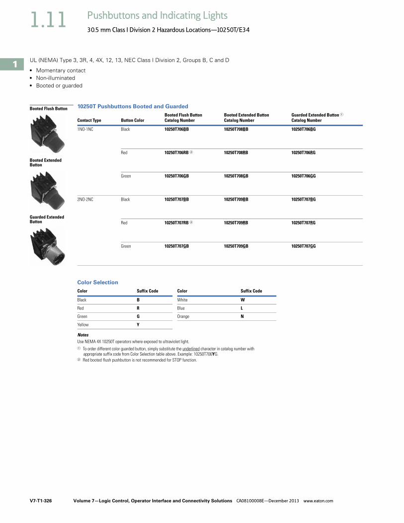
V7-T1-326 Volume 7—Logic Control, Operator Interface and Connectivity Solutions CA08100008E—December 2013 www.eaton.com
1
1
1
1
1
1
1
1
1
1
1
1
1
1
1
1
1
1
1
1
1
1
1
1
1
1
1
1
1
1
1.11 Pushbuttons and Indicating Lights
30.5 mm Class I Division 2 Hazardous Locations—10250T/E34
UL (NEMA) Type 3, 3R, 4, 4X, 12, 13, NEC Class I Division 2, Groups B, C and D
● Momentary contact● Non-illuminated● Booted or guarded
10250T Pushbuttons Booted and Guarded
Color Selection
NotesUse NEMA 4X 10250T operators where exposed to ultraviolet light.1 To order different color guarded button, simply substitute the underlined character in catalog number with
appropriate suffix code from Color Selection table above. Example: 10250T706YG.2 Red booted flush pushbutton is not recommended for STOP function.
Contact Type Button ColorBooted Flush ButtonCatalog Number
Booted Extended ButtonCatalog Number
Guarded Extended Button 1Catalog Number
1NO-1NC Black 10250T706BB 10250T708BB 10250T706BG
Red 10250T706RB 2 10250T708RB 10250T706RG
Green 10250T706GB 10250T708GB 10250T706GG
2NO-2NC Black 10250T707BB 10250T709BB 10250T707BG
Red 10250T707RB 2 10250T709RB 10250T707RG
Green 10250T707GB 10250T709GB 10250T707GG
Color Suffix Code Color Suffix Code
Black B White W
Red R Blue L
Green G Orange N
Yellow Y
Guarded Extended Button
Booted Extended Button
Booted Flush Button
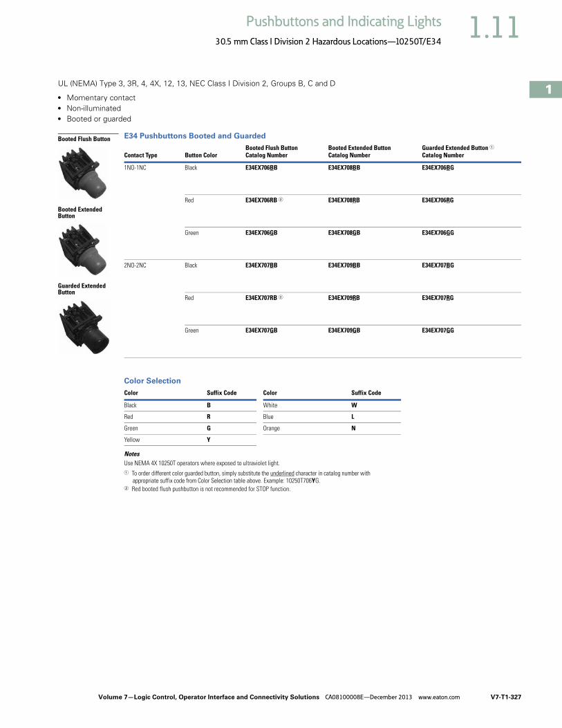
Volume 7—Logic Control, Operator Interface and Connectivity Solutions CA08100008E—December 2013 www.eaton.com V7-T1-327
1
1
1
1
1
1
1
1
1
1
1
1
1
1
1
1
1
1
1
1
1
1
1
1
1
1
1
1
1
1
1.11Pushbuttons and Indicating Lights
30.5 mm Class I Division 2 Hazardous Locations—10250T/E34
UL (NEMA) Type 3, 3R, 4, 4X, 12, 13, NEC Class I Division 2, Groups B, C and D
● Momentary contact● Non-illuminated● Booted or guarded
E34 Pushbuttons Booted and Guarded
Color Selection
NotesUse NEMA 4X 10250T operators where exposed to ultraviolet light.1 To order different color guarded button, simply substitute the underlined character in catalog number with
appropriate suffix code from Color Selection table above. Example: 10250T706YG.2 Red booted flush pushbutton is not recommended for STOP function.
Contact Type Button ColorBooted Flush ButtonCatalog Number
Booted Extended ButtonCatalog Number
Guarded Extended Button 1Catalog Number
1NO-1NC Black E34EX706BB E34EX708BB E34EX706BG
Red E34EX706RB 2 E34EX708RB E34EX706RG
Green E34EX706GB E34EX708GB E34EX706GG
2NO-2NC Black E34EX707BB E34EX709BB E34EX707BG
Red E34EX707RB 2 E34EX709RB E34EX707RG
Green E34EX707GB E34EX709GB E34EX707GG
Color Suffix Code Color Suffix Code
Black B White W
Red R Blue L
Green G Orange N
Yellow Y
Booted Flush Button
Booted Extended Button
Guarded Extended Button
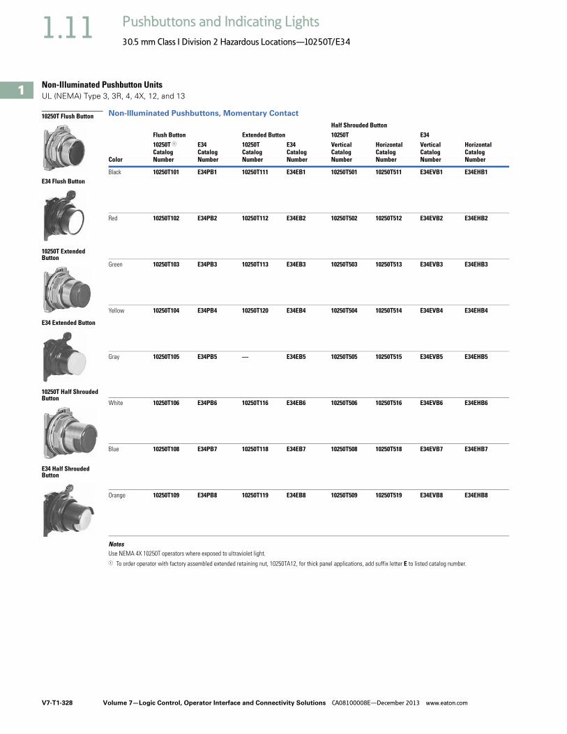
V7-T1-328 Volume 7—Logic Control, Operator Interface and Connectivity Solutions CA08100008E—December 2013 www.eaton.com
1
1
1
1
1
1
1
1
1
1
1
1
1
1
1
1
1
1
1
1
1
1
1
1
1
1
1
1
1
1
1.11 Pushbuttons and Indicating Lights
30.5 mm Class I Division 2 Hazardous Locations—10250T/E34
Non-Illuminated Pushbutton Units UL (NEMA) Type 3, 3R, 4, 4X, 12, and 13
Non-Illuminated Pushbuttons, Momentary Contact
NotesUse NEMA 4X 10250T operators where exposed to ultraviolet light.1 To order operator with factory assembled extended retaining nut, 10250TA12, for thick panel applications, add suffix letter E to listed catalog number.
Color
Half Shrouded ButtonFlush Button Extended Button 10250T E3410250T 1Catalog Number
E34Catalog Number
10250TCatalog Number
E34Catalog Number
VerticalCatalog Number
HorizontalCatalog Number
VerticalCatalog Number
HorizontalCatalog Number
Black 10250T101 E34PB1 10250T111 E34EB1 10250T501 10250T511 E34EVB1 E34EHB1
Red 10250T102 E34PB2 10250T112 E34EB2 10250T502 10250T512 E34EVB2 E34EHB2
Green 10250T103 E34PB3 10250T113 E34EB3 10250T503 10250T513 E34EVB3 E34EHB3
Yellow 10250T104 E34PB4 10250T120 E34EB4 10250T504 10250T514 E34EVB4 E34EHB4
Gray 10250T105 E34PB5 — E34EB5 10250T505 10250T515 E34EVB5 E34EHB5
White 10250T106 E34PB6 10250T116 E34EB6 10250T506 10250T516 E34EVB6 E34EHB6
Blue 10250T108 E34PB7 10250T118 E34EB7 10250T508 10250T518 E34EVB7 E34EHB7
Orange 10250T109 E34PB8 10250T119 E34EB8 10250T509 10250T519 E34EVB8 E34EHB8
10250T Flush Button
E34 Flush Button
10250T Extended Button
E34 Extended Button
10250T Half Shrouded Button
E34 Half Shrouded Button
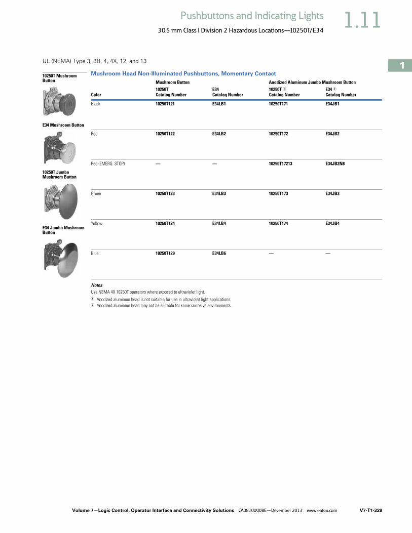
Volume 7—Logic Control, Operator Interface and Connectivity Solutions CA08100008E—December 2013 www.eaton.com V7-T1-329
1
1
1
1
1
1
1
1
1
1
1
1
1
1
1
1
1
1
1
1
1
1
1
1
1
1
1
1
1
1
1.11Pushbuttons and Indicating Lights
30.5 mm Class I Division 2 Hazardous Locations—10250T/E34
UL (NEMA) Type 3, 3R, 4, 4X, 12, and 13
Mushroom Head Non-Illuminated Pushbuttons, Momentary Contact
NotesUse NEMA 4X 10250T operators where exposed to ultraviolet light.1 Anodized aluminum head is not suitable for use in ultraviolet light applications.2 Anodized aluminum head may not be suitable for some corrosive environments.
Color
Mushroom Button Anodized Aluminum Jumbo Mushroom Button10250TCatalog Number
E34Catalog Number
10250T 1Catalog Number
E34 2Catalog Number
Black 10250T121 E34LB1 10250T171 E34JB1
Red 10250T122 E34LB2 10250T172 E34JB2
Red (EMERG. STOP) — — 10250T17213 E34JB2N8
Green 10250T123 E34LB3 10250T173 E34JB3
Yellow 10250T124 E34LB4 10250T174 E34JB4
Blue 10250T129 E34LB6 — —
10250T Mushroom Button
E34 Mushroom Button
10250T Jumbo Mushroom Button
E34 Jumbo Mushroom Button

V7-T1-330 Volume 7—Logic Control, Operator Interface and Connectivity Solutions CA08100008E—December 2013 www.eaton.com
1
1
1
1
1
1
1
1
1
1
1
1
1
1
1
1
1
1
1
1
1
1
1
1
1
1
1
1
1
1
1.11 Pushbuttons and Indicating Lights
30.5 mm Class I Division 2 Hazardous Locations—10250T/E34
Illuminated Pushbutton UnitsUL (NEMA) Type 3, 3R, 4, 4X, 12, 13, NEC Class I Division 2, Groups B, C and D
● Momentary contact● Illuminated● Plastic lenses
Illuminated Pushbuttons
Lens Selection
Note1 To order different color lens, simply substitute the underlined character in the catalog number with appropriate
suffix code from Lens Selection table above. Example: 10250T828YD24.
Type Voltage Color Contact
10250T E34LED/LampNumber Catalog Number 1
LED/LampNumber Catalog Number 1
LED Lamp
Full voltage 24 Vac/Vdc Red 1NO-1NC Bayonetbase
10250T828RD24 Bayonetbase
E34EX828RD24
Green 10250T828GD24 E34EX828GD24
Amber 10250T828AD24 E34EX828AD24
120 Vac Red 1NO-1NC 10250T828RD2A E34EX828RD2A
Green 10250T828GD2A E34EX828GD2A
Amber 10250T828AD2A E34EX828AD2A
Transformer 120 Vac Red 1NO-1NC 10250T802RD06 Bayonetbase6 Vac
E34EX802RD06
Green 10250T802GD06 E34EX802GD06
Amber 10250T802AD06 E34EX802AD06
Incandescent Lamp
Full voltage 24 Vac/Vdc Red 1NO-1NC #757 10250T818RD #757 E34EX818RD
Green 10250T818GD E34EX818GD
Amber 10250T818AD E34EX818AD
Resistor 120 Vac/Vdc Red 1NO-1NC 120MB 10250T824RD 120MB E34EX824RD
Green 10250T824GD E34EX824GD
Amber 10250T824AD E34EX824AD
Transformer 120 Vac Red 1NO-1NC #755 10250T802RD #7556 Vac
E34EX802RD
Green 10250T802GD E34EX802GD
Amber 10250T802AD E34EX802AD
ColorSuffix Code Catalog Number Color
Suffix Code Catalog Number
10250T E34
Red R 10250TC21 Red R E34V2
Green G 10250TC22 Green G E34V3
Yellow Y 10250TC23 Yellow Y E34V4
Amber A 10250TC43 Amber A E34V9
Blue L 10250TC24 Blue L E34V6
Clear C 10250TC25 Clear C E34V0
White W 10250TC26 White W E34V5
10250T8_
E34EX8_
10250TC_
E34V _

Volume 7—Logic Control, Operator Interface and Connectivity Solutions CA08100008E—December 2013 www.eaton.com V7-T1-331
1
1
1
1
1
1
1
1
1
1
1
1
1
1
1
1
1
1
1
1
1
1
1
1
1
1
1
1
1
1
1.11Pushbuttons and Indicating Lights
30.5 mm Class I Division 2 Hazardous Locations—10250T/E34
Guarded Illuminated Pushbutton UnitsUL (NEMA) Type 3, 3R, 4, 4X, 12, 13, NEC Class I Division 2, Groups B, C and D
● Momentary contact● Guarded illuminated● Plastic lenses
Guarded Illuminated Pushbuttons
Lens Selection
Note1 To order different color lens, simply substitute the underlined character in the catalog number with appropriate
suffix code from Lens Selection table above. Example: 10250T828YD24.
Type Voltage Color Contact
10250T E34LED/LampNumber Catalog Number 1
LED/LampNumber Catalog Number 1
LED Lamp
Full voltage 24 Vac/Vdc Red 1NO-1NC Bayonetbase
10250T828RG24 Bayonetbase
E34EX828RG24
Green 10250T828GG24 E34EX828GG24
Amber 10250T828AG24 E34EX828AG24
120 Vac Red 1NO-1NC 10250T828RG2A E34EX828RG2A
Green 10250T828GG2A E34EX828GG2A
Amber 10250T828AG2A E34EX828AG2A
Transformer 120 Vac Red 1NO-1NC 10250T802RG06 E34EX802RG06
Green 10250T802GG06 E34EX802GG06
Amber 10250T802AG06 E34EX802AG06
Incandescent Lamp
Full voltage 24 Vac/Vdc Red 1NO-1NC #757 10250T818RG #757 E34EX818RG
Green 10250T818GG E34EX818GG
Amber 10250T818AG E34EX818AG
Resistor 120 Vac/Vdc Red 1NO-1NC 120MB 10250T824RG 120MB E34EX824RG
Green 10250T824GG E34EX824GG
Amber 10250T824AG E34EX824AG
Transformer 120 Vac Red 1NO-1NC #755 10250T802RG #7556 Vac
E34EX802RG
Green 10250T802GG E34EX802GG
Amber 10250T802AG E34EX802AG
ColorSuffix Code Catalog Number Color
Suffix Code Catalog Number
10250T E34
Red R 10250TC21 Red R E34V2
Green G 10250TC22 Green G E34V3
Yellow Y 10250TC23 Yellow Y E34V4
Amber A 10250TC43 Amber A E34V9
Blue L 10250TC24 Blue L E34V6
Clear C 10250TC25 Clear C E34V0
White W 10250TC26 White W E34V5
10250T8_
E34EX8_
10250TC2_
E34V_

V7-T1-332 Volume 7—Logic Control, Operator Interface and Connectivity Solutions CA08100008E—December 2013 www.eaton.com
1
1
1
1
1
1
1
1
1
1
1
1
1
1
1
1
1
1
1
1
1
1
1
1
1
1
1
1
1
1
1.11 Pushbuttons and Indicating Lights
30.5 mm Class I Division 2 Hazardous Locations—10250T/E34
Indicating Light UnitsUL (NEMA) Type 3, 3R, 3S, 4, 4X, 12, 13, NEC Class I Division 2, Groups B, C and D
● Standard● Plastic lenses
Indicating Lights
Lens Selection
NotesUse NEMA 4X 10250T operators where exposed to ultraviolet light.1 To order different color lens, simply substitute the underlined characters in the catalog number with appropriate suffix code from the Lens Selection table above.
Example: 10250T201HYP.
Type Voltage ColorLED/LampNumber
10250T E34Catalog Number 1 Catalog Number 1
LED Lamp
Full voltage 24 Vac/Vdc Red Bayonetbase
10250T197HLRP24 E34FB197HLRP24
Green 10250T197HLGP24 E34FB197HLGP24
Amber 10250T197HLAP24 E34FB197HLAP24
120 Vac Red 10250T197HLRP2A E34FB197HLRP2A
Green 10250T197HLGP2A E34FB197HLGP2A
Amber 10250T197HLAP2A E34FB197HLAP2A
Transformer 120 Vac Red 10250T181HLRP06 E34TB120HLRP06
Green 10250T181HLGP06 E34TB120HLGP06
Amber 10250T181HLAP06 E34TB120HLAP06
Incandescent Lamp
Full voltage 24 Vac/Vdc Red #757 10250T206HRP E34FB24HRP
Green 10250T206HGP E34FB24HGP
Amber 10250T206HAP E34FB24HAP
Resistor 120 Vac/Vdc Red 120MB 10250T201HRP E34RB120HRP
Green 10250T201HGP E34RB120HGP
Amber 10250T201HAP E34RB120HAP
Transformer 120 Vac Red #755 10250T181HRP E34TB120HRP
Green 10250T181HGP E34TB120HGP
Amber 10250T181HAP E34TB120HAP
Color
Plastic Glass
Color
Plastic GlassSuffix Code Catalog Number
Suffix Code Catalog Number
Suffix Code Catalog Number
Suffix Code Catalog Number
10250T E34
Red RP 10250TC1N RG 10250TC7N Red RP E34H2 RG E34G2
Green GP 10250TC2N GG 10250TC8N Green GP E34H3 GG E34G3
Amber AP 10250TC19N AG 10250TC9N Amber AP E34H9 AG E34G9
Yellow YP 10250TC3N — — Yellow YP E34H4 YG E34G4
Blue LP 10250TC4N LG 10250TC10N Blue LP E34H6 LG E34G6
Clear CP 10250TC5N CG 10250TC11N Clear CP E34H0 CG E34G0
White WP 10250TC6N WG 10250TC12N White WP E34H5 WG E34G5
10250T_
E34_
Glass
Plastic

Volume 7—Logic Control, Operator Interface and Connectivity Solutions CA08100008E—December 2013 www.eaton.com V7-T1-333
1
1
1
1
1
1
1
1
1
1
1
1
1
1
1
1
1
1
1
1
1
1
1
1
1
1
1
1
1
1
1.11Pushbuttons and Indicating Lights
30.5 mm Class I Division 2 Hazardous Locations—10250T/E34
Illuminated Pushbuttons and Indicating LightsNEC Class I Division 2, Groups B, C and D
Operators without Lenses
NotesUse NEMA 4X 10250T operators where exposed to ultraviolet light.1 These units do not include lamps. Order LED separately to match lens color from the LED Selection table on Page V7-T1-343.2 Resister units are not available for use with LEDs, choose either transformer or full voltage LED style.
Illuminated Pushbutton Indicating Light
Type VoltageLED/Lamp Number
10250TCatalog Number
E34Catalog Number
10250TCatalog Number
E34Catalog Number
LED Light Unit Type (LEDs not included) 1
Full voltage — Bayonetbase
10250T397HL E34CB497HL 10250T197HL E34FB197HL
Transformer AC only
24 10250T416HL E34XB024HL — —
120 10250T411HL E34XB120HL 10250T181HL E34TB120HL
240 10250T412HL E34XB240HL 10250T182HL E34TB240HL
277 10250T419HL E34XB277HL 10250T198HL E34TB277HL
380 10250T413HL E34XB380HL 10250T183HL E34TB380HL
480 10250T414HL E34XB480HL 10250T184HL E34TB480HL
600 10250T415HL E34XB600HL 10250T185HL E34TB600HL
Incandescent Light Unit Type
Full voltage AC/DC
6 #755 10250T473H E34CB06H 10250T203H E34FB06H
12 #756 10250T474H E34CB12H 10250T204H E34FB12H
24 #757 10250T476H E34CB24H 10250T206H E34FB24H
32 #1828 10250T477H E34CB32H 10250T207H E34FB32H
48 #1835 10250T478H E34CB48H 10250T208H E34FB48H
Resistor 2AC/DC
120 120MB 10250T471H E34SB120H 10250T201H E34RB120H
240 120MB 10250T472H E34SB240H 10250T202H E34RB240H
Transformer AC only
24 #755 10250T416H E34XB024H — —
120 10250T411H E34XB120H 10250T181H E34TB120H
240 10250T412H E34XB240H 10250T182H E34TB240H
277 10250T419H E34XB277H 10250T198H E34TB277H
380 10250T413H E34XB380H 10250T183H E34TB380H
480 10250T414H E34XB480H 10250T184H E34TB480H
600 10250T415H E34XB600H 10250T185H E34TB600H
NeonAC/DC
120 NE51H-R-22 — — 10250T226H E34NB120H
240 NE51H-4-68 — — 10250T227H E34NB240H
10250T Illuminated Pushbutton
E34 Illuminated Pushbutton
10250T Indicating Light
E34 Indicating Light

V7-T1-334 Volume 7—Logic Control, Operator Interface and Connectivity Solutions CA08100008E—December 2013 www.eaton.com
1
1
1
1
1
1
1
1
1
1
1
1
1
1
1
1
1
1
1
1
1
1
1
1
1
1
1
1
1
1
1.11 Pushbuttons and Indicating Lights
30.5 mm Class I Division 2 Hazardous Locations—10250T/E34
Indicating Light Lenses
Illuminated Pushbutton Lenses
Color10250TCatalog Number
E34Catalog Number
Plastic
Red 10250TC1N E34H2
Green 10250TC2N E34H3
Amber 10250TC19N E34H9
Yellow 10250TC3N E34H4
Blue 10250TC4N E34H6
Clear 10250TC5N E34H0
White 10250TC6N E34H5
Glass
Red 10250TC7N E34G2
Green 10250TC8N E34G3
Amber 10250TC9N E34G9
Yellow — E34G4
Blue 10250TC10N E34G6
Clear 10250TC11N E34G0
White 10250TC12N E34G5
Color10250TCatalog Number
E34Catalog Number
Red 10250TC21 E34V2
Green 10250TC22 E34V3
Yellow 10250TC23 E34V4
Amber 10250TC43 E34V9
Blue 10250TC24 E34V6
Clear 10250TC25 E34V0
White 10250TC26 E34V5
Plastic
Glass
10250TC_
E34H_
10250TC_
E34G_
10250TC_
E34V_

Volume 7—Logic Control, Operator Interface and Connectivity Solutions CA08100008E—December 2013 www.eaton.com V7-T1-335
1
1
1
1
1
1
1
1
1
1
1
1
1
1
1
1
1
1
1
1
1
1
1
1
1
1
1
1
1
1
1.11Pushbuttons and Indicating Lights
30.5 mm Class I Division 2 Hazardous Locations—10250T/E34
Push-Pull UnitsUL (NEMA) Type 3, 3R, 4, 4X, 12, 13, NEC Class I Division 2, Groups B, C and D
● Two- and three-position● Non-illuminated
Two-Position Maintained Push, Maintained Pull
Three-Position Maintained Push, Momentary Pull
Notes1 Bolded circuit corresponds to “X-O” circuit selection. X = closed circuit, O = open circuit.2 To order different type or color buttons, simply substitute underlined character with appropriate suffix code from the Button and Color Selection
table on Page V7-T1-336. Example: 10250T714G.3 To order different type or color buttons, simply substitute underlined character with appropriate suffix code from the Button and Color Selection
table on Page V7-T1-336. Example: 10250T716G.
Operator Function (Position) 1
Contact Type
Maintained—Pull
Maintained—Push
Red Standard Push-Pull 2Mounting Location 1 10250T
Catalog NumberE34Catalog Number1 2
OX
XO
1NO1NC
10250T714R E34EX714R
OXOX
XOXO
2NO2NC
10250T715R E34EX715R
10250T71_
E34EX71_
Operator Function (Position) 1
Contact Type
Momentary—Pull
Maintained—Intermediate
Maintained—Push
Red Standard Push-Pull 3Mounting Location 1 10250T
Catalog NumberE34Catalog Number1 2
OX
OO
XO
1NO1NC
10250T716R E34EX716R
XX
OX
OO
1NC1NC
10250T717R E34EX717R
10250T71_
E34EX71_

V7-T1-336 Volume 7—Logic Control, Operator Interface and Connectivity Solutions CA08100008E—December 2013 www.eaton.com
1
1
1
1
1
1
1
1
1
1
1
1
1
1
1
1
1
1
1
1
1
1
1
1
1
1
1
1
1
1
1.11 Pushbuttons and Indicating Lights
30.5 mm Class I Division 2 Hazardous Locations—10250T/E34
UL (NEMA) Type 3, 3R, 4, 4X, 12, 13, NEC Class I Division 2, Groups B, C and D
● Two- and three-position● Non-illuminated
Three-Position Momentary Push, Momentary Pull
Button and Color Selection
Notes1 Bolded circuit corresponds to “X-O” circuit selection. X = closed circuit, O = open circuit.2 To order different type or color buttons, simply substitute underlined character with appropriate suffix code from the
Button and Color Selection table above. Example: 10250T718G.
Operator Function (Position) 1
Contact Type
Momentary—Pull
Maintained—Intermediate
Momentary—Push
Red Standard Push-Pull 2Mounting Location 1 10250T
Catalog NumberE34Catalog Number1 2
OX
OO
XO
1NO1NC
10250T718R E34EX718R
XX
OX
OO
1NC1NC
10250T721R E34EX721R
ColorSuffixCode
10250TCatalog Number
E34Catalog Number
Standard
Red R 10250TB62 E34C2
Red (EMERG. STOP) E 10250TB63 E34C2N8
Green G 10250TB61 E34C3
Black B 10250TB60 E34C1
Blue L 10250TB64 E34C6
Jumbo Mushroom Head (Anodized) Aluminum
Red RJ 10250TJ62 E34J2
Red (EMERG. STOP) EJ 10250TJ63 E34J2N8
Green GJ 10250TJ61 —
Black BJ 10250TJ60 —
Yellow YJ 10250TJ64 —
10250T7_
E34EX7_
Standard
Jumbo Mushroom Head

Volume 7—Logic Control, Operator Interface and Connectivity Solutions CA08100008E—December 2013 www.eaton.com V7-T1-337
1
1
1
1
1
1
1
1
1
1
1
1
1
1
1
1
1
1
1
1
1
1
1
1
1
1
1
1
1
1
1.11Pushbuttons and Indicating Lights
30.5 mm Class I Division 2 Hazardous Locations—10250T/E34
Illuminated Push-Pull Units UL (NEMA) Type 3, 3R, 4, 4X, 12, 13, NEC Class I Division 2, Groups B, C and D
● Two-position maintained● Illuminated
Two-Position Illuminated Maintained Push, Maintained Pull
Lens and Color Selection
Notes1 Bolded circuit corresponds to “X-O” circuit selection. X = closed circuit, O = open circuit.2 To order different type or color lens, simply substitute the underlined characters with appropriate suffix code from the
Lens and Color Selection table above. Example: 10250T851GS.
Operator Function (Position) 1
Type VoltageContact Type
Maintained—Pull
Maintained—Push
Red Standard Push-Pull 2Mounting Location 1 10250T
Catalog NumberE34Catalog Number1 2
LED Lamp
OX
XO
Full voltage 24 Vac/Vdc 1NO1NC
10250T853RD24 E34EX853RD24
120 Vac 10250T853RD2A E34EX853RD2A
Transformer 24 Vac 10250T843RD06 E34EX843RD06
120 Vac 10250T844RD06 E34EX844RD06
Incandescent Lamp
OX
XO
Full voltage 24 Vac/Vdc 1NO1NC
10250T849RD E34EX849RD
Resistor 120 Vac/Vdc 10250T851RD E34EX851RD
Transformer 24 Vac 10250T843RD E34EX843RD
120 Vac 10250T844RD E34EX844RD
10250T E34Color Suffix Code Catalog Number Suffix Code Catalog Number
Standard
Red RD 10250TC47 RD E34M2
Red (EMERG. STOP) ED 10250TC53 ED E34M2N8
Green GD 10250TC48 GD E34M3
Blue LD 10250TC49 LD E34M6
Amber AD 10250TC50 AD E34M9
White WD 10250TC51 WD E34M5
Clear CD 10250TC52 CD E34M0
Side-Lighted (Anodized) Aluminum
Red RS 10250TC57 — —
Red (EMERG. STOP) ES 10250TC63 — —
Green GS 10250TC58 — —
Blue LS 10250TC59 — —
Amber AS 10250TC64 — —
Yellow YS 10250TC60
White WS 10250TC61 — —
Clear CS 10250TC62 — —
Heavy-Duty Aluminum with Transparent Center
Red RH 10250TC65 — —
Green GH 10250TC66 — —
Amber AH 10250TC67 — —
10250T8_
E34EX8_
Standard
Side-Lighted (Anodized) Aluminum
HD Aluminum with Transparent Center

V7-T1-338 Volume 7—Logic Control, Operator Interface and Connectivity Solutions CA08100008E—December 2013 www.eaton.com
1
1
1
1
1
1
1
1
1
1
1
1
1
1
1
1
1
1
1
1
1
1
1
1
1
1
1
1
1
1
1.11 Pushbuttons and Indicating Lights
30.5 mm Class I Division 2 Hazardous Locations—10250T/E34
UL (NEMA) Type 3, 3R, 4, 4X, 12, 13, NEC Class I Division 2, Groups B, C and D
● Three-position—maintained push, momentary pull● Illuminated
Three-Position Illuminated Maintained Push, Momentary Pull
Notes1 Bolded circuit corresponds to “X-O” circuit selection. X = closed circuit, O = open circuit.2 To order different type or color lens, simply substitute the underlined characters with appropriate suffix code from the Lens and
Color Selection table on the bottom of Page V7-T1-337. Example: 10250T862AS.
Operator Function (Position) 1
Type VoltageContact Type
Momentary—Pull
Maintained—Intermediate
Maintained—Push
Red Standard Push-Pull 2Mounting Location 1 10250T
Catalog NumberE34Catalog Number1 2
LED Lamp
OX
OO
XO
Full voltage 24 Vac/Vdc 1NO1NC
10250T864RD24 E34EX864RD24
120 Vac 10250T864RD2A E34EX864RD2A
Transformer 24 Vac 10250T854RD06 E34EX854RD06
120 Vac 10250T855RD06 E34EX855RD06
XX
OX
OO
Full voltage 24 Vac/Vdc 1NC1NC
10250T875RD24 E34EX875RD24
120 Vac 10250T875RD2A E34EX875RD2A
Transformer 24 Vac 10250T865RD06 E34EX865RD06
120 Vac 10250T866RD06 E34EX866RD06
Incandescent Lamp
OX
OO
XO
Full voltage 24 Vac/Vdc 1NO1NC
10250T860RD E34EX860RD
Resistor 120 Vac 10250T862RD E34EX862RD
Transformer 24 Vac 10250T854RD E34EX854RD
120 Vac 10250T855RD E34EX855RD
XX
OX
OO
Full voltage 24 Vac/Vdc 1NC1NC
10250T871RD E34EX871RD
Resistor 120 Vac 10250T873RD E34EX873RD
Transformer 24 Vac 10250T865RD E34EX865RD
120 Vac 10250T866RD E34EX866RD
E34EX8_
10250T8_

Volume 7—Logic Control, Operator Interface and Connectivity Solutions CA08100008E—December 2013 www.eaton.com V7-T1-339
1
1
1
1
1
1
1
1
1
1
1
1
1
1
1
1
1
1
1
1
1
1
1
1
1
1
1
1
1
1
1.11Pushbuttons and Indicating Lights
30.5 mm Class I Division 2 Hazardous Locations—10250T/E34
UL (NEMA) Type 3, 3R, 4, 4X, 12, 13, NEC Class I Division 2, Groups B, C and D
● Three-position—momentary● Illuminated
Three-Position Illuminated Momentary Push, Momentary Pull
Notes1 Bolded circuit corresponds to “X-O” circuit selection. X = closed circuit, O = open circuit.2 To order different type or color lens, simply substitute the underlined characters with appropriate suffix code from the Lens and
Color Selection table on the bottom of Page V7-T1-337. Example: 10250T862AS.
Operator Function (Position) 1
Type VoltageContact Type
Momentary—Pull
Maintained—Intermediate
Maintained—Push
Red Standard Push-Pull 2Mounting Location 1 10250T
Catalog NumberE34Catalog Number1 2
LED Lamp
OX
OO
XO
Full voltage 24 Vac/Vdc 1NO1NC
10250T886RD24 E34EX886RD24
120 Vac 10250T886RD2A E34EX886RD2A
Transformer 24 Vac 10250T876RD06 E34EX876RD06
120 Vac 10250T877RD06 E34EX877RD06
XX
OX
OO
Full voltage 24 Vac/Vdc 1NC1NC
10250T897RD24 E34EX897RD24
120 Vac 10250T897RD2A E34EX897RD2A
Transformer 24 Vac 10250T887RD06 E34EX887RD06
120 Vac 10250T888RD06 E34EX888RD06
Incandescent Lamp
OX
OO
XO
Full voltage 24 Vac/Vdc 1NO1NC
10250T882RD E34EX882RD
Resistor 120 Vac 10250T884RD E34EX884RD
Transformer 24 Vac 10250T876RD E34EX876RD
120 Vac 10250T877RD E34EX877RD
XX
OX
OO
Full voltage 24 Vac/Vdc 1NC1NC
10250T893RD E34EX893RD
Resistor 120 Vac 10250T895RD E34EX895RD
Transformer 24 Vac 10250T887RD E34EX887RD
120 Vac 10250T888RD E34EX888RD
E34EX8_
10250T8_
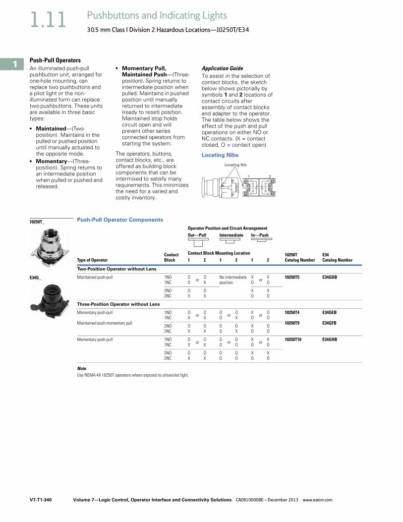
V7-T1-340 Volume 7—Logic Control, Operator Interface and Connectivity Solutions CA08100008E—December 2013 www.eaton.com
1
1
1
1
1
1
1
1
1
1
1
1
1
1
1
1
1
1
1
1
1
1
1
1
1
1
1
1
1
1
1.11 Pushbuttons and Indicating Lights
30.5 mm Class I Division 2 Hazardous Locations—10250T/E34
Push-Pull OperatorsAn illuminated push-pull pushbutton unit, arranged for one-hole mounting, can replace two pushbuttons and a pilot light or the non-illuminated form can replace two pushbuttons. These units are available in three basic types:
● Maintained—(Two-position). Maintains in the pulled or pushed position until manually actuated to the opposite mode.
● Momentary—(Three-position). Spring returns to an intermediate position when pulled or pushed and released.
● Momentary Pull, Maintained Push—(Three-position). Spring returns to intermediate position when pulled. Maintains in pushed position until manually returned to intermediate (ready to reset) position. Maintained stop holds circuit open and will prevent other series connected operators from starting the system.
The operators, buttons, contact blocks, etc., are offered as building block components that can be intermixed to satisfy many requirements. This minimizes the need for a varied and costly inventory.
Application GuideTo assist in the selection of contact blocks, the sketch below shows pictorially by symbols 1 and 2 locations of contact circuits after assembly of contact blocks and adapter to the operator. The table below shows the effect of the push and pull operations on either NO or NC contacts. (X = contact closed, O = contact open).
Locating Nibs
Push-Pull Operator Components
NoteUse NEMA 4X 10250T operators where exposed to ultraviolet light.
Locating Nib
1 2
Type of OperatorContactBlock
Operator Position and Circuit Arrangement
10250TCatalog Number
E34Catalog Number
Out—Pull Intermediate In—Push
Contact Block Mounting Location1 2 1 2 1 2
Two-Position Operator without Lens
Maintained push-pull 1NO1NC
OX or O
XNo intermediateposition
XO or X
O10250T5 E34GDB
2NO2NC
OX
OX
XO
XO
Three-Position Operator without Lens
Momentary push-pull
Maintained push-momentary pull
1NO1NC
OX or O
XOO or O
XXO or O
O10250T4
10250T9
E34GEB
E34GFB2NO2NC
OX
OX
OO
OX
XO
OO
Momentary push-pull 1NO1NC
OX or O
XOO or O
OXO or X
O10250T10 E34GHB
2NO2NC
OX
OX
OO
OO
XO
XO
10250T_
E34G_

Volume 7—Logic Control, Operator Interface and Connectivity Solutions CA08100008E—December 2013 www.eaton.com V7-T1-341
1
1
1
1
1
1
1
1
1
1
1
1
1
1
1
1
1
1
1
1
1
1
1
1
1
1
1
1
1
1
1.11Pushbuttons and Indicating Lights
30.5 mm Class I Division 2 Hazardous Locations—10250T/E34
Push-Pull Light Units, Lenses and ButtonsNEC Class I Division 2 Groups B, C and D
Light Units for Illuminated Push-Pull Devices
Note1 These units do not include lamps. Order LED separately to match lens color from table on Page V7-T1-343.
Light Unit Type Type Voltage
LED/LampNumber Catalog Number
LED(LEDs not included) 1
Full voltage — Bayonetbase
10250T97HL
Transformer AC only50/60 Hz
24 10250T89HL
120 10250T63HL
208 10250T64HL
240 10250T65HL
277 10250T82HL
380 10250T66HL
480 10250T67HL
600 10250T68HL
Incandescent Full voltageAC or DC
6 #755#756#757#1828
10250T69H
12 10250T70H
24/28 10250T79H
32 10250T83H
Resistor AC or DC
120 120MB 10250T80H
240 10250T81H
Transformer AC only50/60 Hz
24 #755 10250T89H
120 10250T63H
208 10250T64H
240 10250T65H
277 10250T82H
380 10250T66H
480 10250T67H
600 10250T68H
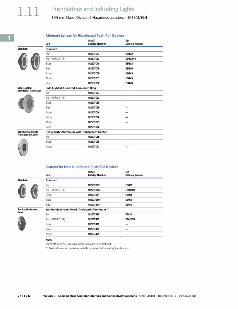
V7-T1-342 Volume 7—Logic Control, Operator Interface and Connectivity Solutions CA08100008E—December 2013 www.eaton.com
1
1
1
1
1
1
1
1
1
1
1
1
1
1
1
1
1
1
1
1
1
1
1
1
1
1
1
1
1
1
1.11 Pushbuttons and Indicating Lights
30.5 mm Class I Division 2 Hazardous Locations—10250T/E34
Alternate Lenses for Illuminated Push-Pull Devices
Buttons for Non-Illuminated Push-Pull Devices
NotesUse NEMA 4X 10250T operators where exposed to ultraviolet light.1 Anodized aluminum head is not suitable for use with ultraviolet light applications.
Color10250TCatalog Number
E34Catalog Number
Standard
Red 10250TC47 E34M2
Red (EMERG. STOP) 10250TC53 E34M2N8
Green 10250TC48 E34M3
Blue 10250TC49 E34M6
Amber 10250TC50 E34M9
White 10250TC51 E34M5
Clear 10250TC52 E34M0
Side-Lighted Anodized Aluminum Ring
Red 10250TC57 —
Red (EMERG. STOP) 10250TC63 —
Green 10250TC58 —
Blue 10250TC59 —
Amber 10250TC64 —
Yellow 10250TC60 —
White 10250TC61 —
Clear 10250TC62 —
Heavy-Duty Aluminum with Transparent Center
Red 10250TC65 —
Green 10250TC66 —
Amber 10250TC67 —
Color10250TCatalog Number
E34Catalog Number
Standard
Red 10250TB62 E34C2
Red (EMERG. STOP) 10250TB63 E34C2N8
Green 10250TB61 E34C3
Black 10250TB60 E34C1
Blue 10250TB64 E34C6
Jumbo Mushroom Head (Anodized) Aluminum 1
Red 10250TJ62 E34J2
Red (EMERG. STOP) 10250TJ63 E34J2N8
Green 10250TJ61 —
Black 10250TJ60 —
Yellow 10250TJ64 —
Standard
Side-Lighted (Anodized) Aluminum
HD Aluminum with Transparent Center
Standard
Jumbo Mushroom Head

Volume 7—Logic Control, Operator Interface and Connectivity Solutions CA08100008E—December 2013 www.eaton.com V7-T1-343
1
1
1
1
1
1
1
1
1
1
1
1
1
1
1
1
1
1
1
1
1
1
1
1
1
1
1
1
1
1
1.11Pushbuttons and Indicating Lights
30.5 mm Class I Division 2 Hazardous Locations—10250T/E34
LED Selection
NoteFor a complete listing of all LEDs available, see Page V7-T1-239.
Voltage Color Catalog Number Voltage Color Catalog Number
6 Vac/Vdcsuitable foruse withtransformers
Red E22LED006RN 60 Vac/Vdc Red E22LED060RN
Orange E22LED006ON Orange E22LED060ON
Yellow E22LED006YN Yellow E22LED060YN
Green E22LED006GN Green E22LED060GN
Blue E22LED006BN Blue E22LED060BN
White E22LED006WN White E22LED060WN
12 Vac/Vdc Red E22LED012RN 120 Vac Red E22LED120RA
Orange E22LED012ON Orange E22LED120OA
Yellow E22LED012YN Yellow E22LED120YA
Green E22LED012GN Green E22LED120GA
Blue E22LED012BN Blue E22LED120BA
White E22LED012WN White E22LED120WA
24 Vac/Vdc Red E22LED024RN 120 Vdc Red E22LED120RD
Orange E22LED024ON Orange E22LED120OD
Yellow E22LED024YN Yellow E22LED120YD
Green E22LED024GN Green E22LED120GD
Blue E22LED024BN Blue E22LED120BD
White E22LED024WN White E22LED120WD
48 Vac/Vdc Red E22LED048RN
Orange E22LED048ON
Yellow E22LED048YN
Green E22LED048GN
Blue E22LED048BN
White E22LED048WN
Standard LED Lamp

V7-T1-344 Volume 7—Logic Control, Operator Interface and Connectivity Solutions CA08100008E—December 2013 www.eaton.com
1
1
1
1
1
1
1
1
1
1
1
1
1
1
1
1
1
1
1
1
1
1
1
1
1
1
1
1
1
1
1.11 Pushbuttons and Indicating Lights
30.5 mm Class I Division 2 Hazardous Locations—10250T/E34
Selector Switch UnitsUL (NEMA) Type 3, 3R, 4, 4X, 12, 13, NEC Class I Division 2, Groups B, C and D
● Two- and three-position● Non-illuminated
Two-Position Selector Switch—Non-Illuminated
Three-Position Selector Switch—Non-Illuminated
Notes1 Bolded circuit corresponds to “X-O” circuit selection. X = closed circuit, O = open circuit.2 M = Maintained. S = Spring return in direction of arrow (W).3 To order different type or color selector switch, simply substitute the underlined characters with appropriate
suffix code from the table on Page V7-T1-345. Example: 10250T722LL. For keyed selector switch, substitute the underlined characters withT_ (cam)+_ (key removal position). Example: 10250T722T13.
4 To order different type or color selector switch, simply substitute the underlined characters with appropriate suffix code from the Switch and Color Selection table on Page V7-T1-345. Example: 10250T726LL. For keyed selector switch, substitute the underlined characters withT_ (cam)+_ (key removal position). Example: 10250T726T13.
Operator Position 1
Operator Action 2
ContactType
Cam Code
Black Knob—Selector Switch 3 Mounting Location 1 10250T
Catalog NumberE34Catalog Number1 2
XO
OX
1NC1NO
1 10250T722BK E34EX722BK
10250T724BK E34EX724BK
XOXO
OXOX
1NC1NO1NC1NO
1 10250T723BK E34EX723BK
10250T725BK E34EX725BK
Operator Position 1
Operator Action 2
ContactType
Cam Code
Black Knob—Selector Switch 4 Mounting Location 1 10250T
Catalog NumberE34Catalog Number1 2
XO
OO
OX
1NO1NO
3 10250T726BK E34EX726BK
10250T728BK E34EX728BK
10250T730BK E34EX730BK
10250T732BK E34EX732BK
XOO
OXO
OOX
1NO1NC-1NC(Series)1NO
3 10250T727BK E34EX727BK
10250T729BK E34EX729BK
10250T731BK E34EX731BK
10250T733BK E34EX733BK
10250T72_
E34EX72_
M M
M S
M M
M S
10250T_
M M
M
MS
M
S S
M
M S
M
M M
M
MS
M
S S
M
M S
M

Volume 7—Logic Control, Operator Interface and Connectivity Solutions CA08100008E—December 2013 www.eaton.com V7-T1-345
1
1
1
1
1
1
1
1
1
1
1
1
1
1
1
1
1
1
1
1
1
1
1
1
1
1
1
1
1
1
1.11Pushbuttons and Indicating Lights
30.5 mm Class I Division 2 Hazardous Locations—10250T/E34
UL (NEMA) Type 3, 3R, 4, 4X, 12, 13, NEC Class I Division 2, Groups B, C and D
● Four-position maintained● Non-illuminated
Four-Position Selector Switch—Non-Illuminated
Switch and Color Selection
Key Operated Selection Key Removal Positions 7
Notes1 Bolded circuit corresponds to “X-O” circuit selection. X = closed circuit, O = open circuit.2 M = Maintained. 3 To order different type or color selector switch, simply substitute the underlined characters with appropriate suffix code from the
Switch and Color Selection table above. Example: 10250T743LL. For keyed selector switch, substitute the underlined characters with T_ (cam) + _ (key removal position). Example: 10250T743T77.
4 Designed for added ingress protection. For use in maintained operators only.5 10250T only.6 M = Maintained. S = Spring return in direction of arrow (W).7 Key removal in “spring return from” positions not recommended.
Operator Position 1
Operator Action 2
Contact Type
Cam Code
Black Knob—Selector Switch 3 Mounting Location 1 10250T
Catalog NumberE34Catalog Number1 2
XOOO
OXOO
OOXO
OOOX
1NC1NO1NO1NC
7 10250T743BK E34EX743BK
ColorKnob Suffix Code
Lever Suffix Code
Lever 4
Suffix CodeCoin Slot 5Suffix Code
Black BK BL BA BC
Red RK RL RA RC
Green GK GL GA GC
Yellow YK YL YA YC
White WK WL WA WC
Gray AK AL AA AC
Blue LK LL LA LC
Orange NK NL NA NC
10250T743_
E34EX743_M M
M M
Knob
Lever
Coin Slot 5
Number of Position
Operator Action 6
Suffix and RemovalPosition
2 M M T1 + 1, 2, 3
M Q S T1 + 2
3 M M M T3 + 1–7
S W M M T3 + 1, 4, 5
S W M Q S T3 + 4
M M Q S T3 + 2, 4, 6
4 MMMM T7 + 7
CodeSuffix
Key RemovalPosition
1 Right only
2 Left only
3 Right and left
4 Center only
6 Left and center
7 All positions
L
C
R

V7-T1-346 Volume 7—Logic Control, Operator Interface and Connectivity Solutions CA08100008E—December 2013 www.eaton.com
1
1
1
1
1
1
1
1
1
1
1
1
1
1
1
1
1
1
1
1
1
1
1
1
1
1
1
1
1
1
1.11 Pushbuttons and Indicating Lights
30.5 mm Class I Division 2 Hazardous Locations—10250T/E34
Selector Switch Selection
Cam and Contact Block SelectionSelector switches in their varied forms (two-position, three-position, and four-position) are a big factor contributing to the great flexibility of control that a well rounded line of “pushbuttons” can achieve. Because of their flexibility, they tend to cause difficulty with product selection and application. The following systematic approach should simplify that task.
Cam and contact block selection is better understood if you:
● Work with each incoming and outgoing wire/circuit separately.
● Recognize the terms NO and NC only identify the type of contact by its mode before mounting to the operator. The “X-O” table (Page V7-T1-348) shows how that contact will act after assembly to the operator with the selected cam shape. X = closed circuit, O = open circuit.
● One NO-NC contact block may be mounted behind each plunger of the mounting adapter for a total of four circuits.
● Each cam has two separate lobes, each of which operates one of the two contact block plungers independently of each other. Those are identified as position 1 (locating nib side) and position 2 (opposite of locating nib). The position designations give direction in selecting and mounting of the contact blocks.
Contact Circuit Locations
10250T E34
Locating Nib
1 2
Systematic ApproachApplication: HAND-OFF-AUTO selector switch. In this circuit, one incoming line is distributed to two other outgoing circuits by the switch. The two circuits can be looked at individually.
Step 1: Elementary Diagram. Construct on paper, or in your mind, a simple elementary diagram of the switching scheme as follows:
Step 2: “X-O” Pattern. From the elementary diagram, you can construct an “X-O” diagram which describes when the contacts are to be closed (X) or open (O) in the various positions of the switch. The “X-O” for the HAND circuit looks like this:
In this circuit, you want a contact closed on the left (HAND) but open in the center and right.
For the AUTO circuit, the “X-O” diagram would look like this:
Putting them together, the complete “X-O” diagram is:
Once the “X-O” diagram has been generated, the next step is to select the cam and contact block, or blocks, needed to perform the desired “X-O” functions. The selection tables on the following pages list the various types (shapes) of cams by number to choose from and the type of contact and position to achieve the function outlined in your “X-O” diagram.
OFF
HAND OutgoingCircuit
AUTO
OutgoingCircuit
IncomingLine
HAND OFF AUTO
X O O
HAND OFF AUTO
O O X
X O OO O X

Volume 7—Logic Control, Operator Interface and Connectivity Solutions CA08100008E—December 2013 www.eaton.com V7-T1-347
1
1
1
1
1
1
1
1
1
1
1
1
1
1
1
1
1
1
1
1
1
1
1
1
1
1
1
1
1
1
1.11Pushbuttons and Indicating Lights
30.5 mm Class I Division 2 Hazardous Locations—10250T/E34
Step 3: Cam Selection. The cam you select determines the operation of all contact blocks mounted to the operator. It is selected on the basis that it provides the simplest circuitry for the desired “X-O” diagram. The selection tables show all the “X-O” combinations. For the purpose of this example, the applicable portion of those tables is shown on this page.
Now to make the cam selection, make a simple worksheet such as below. (1) or (2) = mounting location from chart above:
It becomes obvious that cam 3 is the better choice because the series connection can be avoided, making it simpler to wire.
Step 4: Contact Block Selection. Having selected the cam, contact block selection is simply a matter of determining if you require one NO-NC contact block (Cat. No 10250T1H) or two. Given the limitations of the factory sealed contact block and the desired “X-O” application, you may have circuits that will not be needed—as seen here with the two additional NC circuits. (1) or (2) = mounting location from chart above.
Step 5: Selector Switch Operator. Lastly, you have to choose from the many types of operators—knob and lever in various colors or keyed. Also what combinations of maintained and spring return functions are required. Selection of these operators can be found on Page V7-T1-349. For the example in step 4, you may want a three-position maintained black knob, cam 3—Catalog Number 10250T1323 (or 34VHBK1).
The Complete Switch: 10250T1323 (or 34VHBK1) with two 10250T1H or for one composite catalog number—10250T726BK (or E34EX726BK) found on Page V7-T1-344.
DiagramsCircuits shown illustrate connections to obtain a selector circuit combination and are shown with their appropriate line diagrams in BOLD. Field wiring of jumper connections required as shown.
X = Closed circuitO = Open circuit
Cam 2 Cam 3
X O OO O X
(1)NO-(2)NC(2)NO
(1)NO(2)NO
1
Qty Catalog No. Cam 3
2 10250TIH (1)NO (2)NC(1)NC (2)NO
Example Selection Table
Note1 Wired in series.
No.
Desired Circuit and Operator Position
Cam Code #2Contact Blocks and Mounting Location
Cam Code #3Contact Blocks and Mounting Location
1 2 1 2
1 X O O
NO NC 1 NO
—
4 O O X —
NO
—
NO
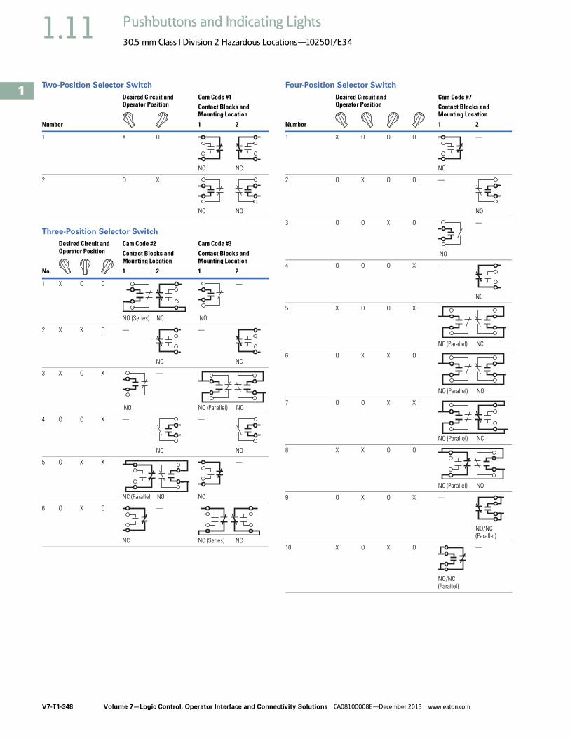
V7-T1-348 Volume 7—Logic Control, Operator Interface and Connectivity Solutions CA08100008E—December 2013 www.eaton.com
1
1
1
1
1
1
1
1
1
1
1
1
1
1
1
1
1
1
1
1
1
1
1
1
1
1
1
1
1
1
1.11 Pushbuttons and Indicating Lights
30.5 mm Class I Division 2 Hazardous Locations—10250T/E34
Two-Position Selector Switch
Three-Position Selector Switch
Four-Position Selector Switch
Number
Desired Circuit and Operator Position
Cam Code #1Contact Blocks and Mounting Location
1 2
1 X O
NC NC
2 O X
NO NO
No.
Desired Circuit and Operator Position
Cam Code #2Contact Blocks and Mounting Location
Cam Code #3Contact Blocks and Mounting Location
1 2 1 2
1 X O O
NO (Series) NC NO
—
2 X X O —
NC
—
NC
3 X O X
NO
—
NO (Parallel) NO
4 O O X —
NO
—
NO
5 O X X
NC (Parallel) NO NC
—
6 O X O
NC
—
NC (Series) NC
Number
Desired Circuit and Operator Position
Cam Code #7Contact Blocks and Mounting Location
1 2
1 X O O O
NC
—
2 O X O O —
NO
3 O O X O
NO
—
4 O O O X —
NC
5 X O O X
NC (Parallel) NC
6 O X X O
NO (Parallel) NO
7 O O X X
NO (Parallel) NC
8 X X O O
NC (Parallel) NO
9 O X O X —
NO/NC(Parallel)
10 X O X O
NO/NC(Parallel)
—

Volume 7—Logic Control, Operator Interface and Connectivity Solutions CA08100008E—December 2013 www.eaton.com V7-T1-349
1
1
1
1
1
1
1
1
1
1
1
1
1
1
1
1
1
1
1
1
1
1
1
1
1
1
1
1
1
1
1.11Pushbuttons and Indicating Lights
30.5 mm Class I Division 2 Hazardous Locations—10250T/E34
Selector Switch Operators
10250T Selector Switch Operators with CapsUL (NEMA) Type 3, 3R, 4, 4X, 12, 13
10250T Selector Switch Operators with Caps
10250T Key Operators with Cam
Key Removal Positions 5 Replacement Keys or Dissimilar Locks for Above Key OperatorsListed operators have identical locks and keys (Key Code H661) Catalog Number 10250ED824.
Replacement Keys
Notes1 M = Maintained. S = Spring return in direction of arrow (W).2 Field convertible to horizontal mounting or order operator only and separate operator cap.3 For selection of the proper cam and contact block to obtain the proper circuit sequence, see selection instructions and table on Pages V7-T1-346 to V7-T1-348.4 Choose key removal position required for application from table above. Add key removal code no. to listed catalog number. Example: 10250T15112.5 Key removal in “spring return from” positions not recommended.
Positions Operator Action 1
Black Knob Selector Switch—Vertical Mounting 2
Black Lever Selector Switch—Vertical Mounting 2
Cam Code 3 Catalog Number Cam Code 3 Catalog Number
Two-position—60° throw 1 10250T1311 1 10250T3011
1 10250T1371 1 10250T3071
Three-position—60° throw 2 10250T1322 2 10250T3022
3 10250T1323 3 10250T3023
2 10250T1332 2 10250T3032
3 10250T1333 3 10250T3033
2 10250T1342 2 10250T3042
3 10250T1343 3 10250T3043
2 10250T1352 2 10250T3052
3 10250T1353 3 10250T3053
Four-position—40° throw 7 10250T1367 7 10250T3067
Positions Operator Action 1 Cam Code 3Optional Key Removal Positions 4
Vertical MountingCatalog Number 4
Horizontal MountingCatalog Number 4
Two-position—60° throw 1 1, 2, 3 10250T1511_ 10250T1611_
1 2 10250T1571_ 10250T1581_
Three-position—60° throw 2 1–7 10250T1522_ 10250T1622_
3 10250T1523_ 10250T1623_
2 1, 4, 5 10250T1532_ 10250T1632_
3 10250T1533_ 10250T1633_
2 4 10250T1542_ 10250T1642_
3 10250T1543_ 10250T1643_
2 2, 4, 6 10250T1652_ 10250T1662_
3 10250T1653_ 10250T1663_
Four-position—40° throw 7 7 10250T1677_ 10250T1687_
Black Knob Selector Switch
Black Lever Selector Switch
M M
M S
M M
M
MS
M
S S
M
M S
M
M M
M M
Horizontal Mounting
M M
M S
M M
M
MS
M
S S
M
M S
M
M M
M M
CodeSuffix
Key RemovalPosition
CodeSuffix
Key RemovalPosition
1 Right only 5 Right and center
2 Left only 6 Left and center
3 Right and left 7 All positions
4 Center only
L
C
R
Key Removal Positions
Description Catalog Number
Replacement keys (code H661) 10250ED824

V7-T1-350 Volume 7—Logic Control, Operator Interface and Connectivity Solutions CA08100008E—December 2013 www.eaton.com
1
1
1
1
1
1
1
1
1
1
1
1
1
1
1
1
1
1
1
1
1
1
1
1
1
1
1
1
1
1
1.11 Pushbuttons and Indicating Lights
30.5 mm Class I Division 2 Hazardous Locations—10250T/E34
UL (NEMA) Type 3, 3R, 4, 4X, 12, 13
E34 Selector Switch Operators with Knob Assembled
E34 Key Operators with Cam and Cap
NotesUse NEMA 4X 10250T operators where exposed to ultraviolet light, see Page V7-T1-349.1 M = Maintained. S = Spring return in direction of arrow (W).2 Field convertible to horizontal mounting. 3 For selection of the proper cam and contact block to obtain the proper circuit sequence, see selection instructions and table on Pages V7-T1-346 to V7-T1-348.4 For other colors of either knob or lever, replace the underlined characters of the catalog number with the appropriate suffix code from Alternate Knobs and Levers table on
Page V7-T1-351. Example: E34VFBL2.5 Choose key removal position required for application from table on Page V7-T1-351. Add key removal code no. to listed catalog number. Example: E34KFB2.
Positions Operator Action 1
Black Knob Selector Switch—Vertical Mounting 2
Cam Code 3 Catalog Number 4
Two-position—60° throw 1 E34VFBK1
1 E34VEBK1
Three-position—60° throw 2 E34VGBK1
3 E34VHBK1
2 E34VJBK1
3 E34VKBK1
2 E34VLBK1
3 E34VMBK1
2 E34VNBK1
3 E34VPBK1
Four-position—40° throw 7 E34VTBK1
Positions Operator Action 1 Cam Code 3Key Removal Positions 5
Vertical MountingCatalog Number
Horizontal MountingCatalog Number
Two-position—60° throw 1 1, 2, 3 E34KFB_ E34KFHB_
1 2 E34KEB_ E34KEHB_
Three-position—60° throw 2 1–7 E34KGB_ E34KGHB_
3 E34KHB_ E34KHHB_
2 1, 4, 5 E34KJB_ E34KJHB_
3 E34KKB_ E34KKHB_
2 4 E34KLB_ E34KLHB_
3 E34KMB_ E34KMHB_
2 2, 4, 6 E34KNB_ E34KNHB_
3 E34KPB_ E34KPHB_
Four-position—40° throw 7 7 E34KTB_ E34KTHB_
Black Knob Selector Switch
M M
M S
M M
M
MS
M
S S
M
M S
M
M M
M M
E34KFB_
M M
M S
M M
M
MS
M
S S
M
M S
M
M M
M M

Volume 7—Logic Control, Operator Interface and Connectivity Solutions CA08100008E—December 2013 www.eaton.com V7-T1-351
1
1
1
1
1
1
1
1
1
1
1
1
1
1
1
1
1
1
1
1
1
1
1
1
1
1
1
1
1
1
1.11Pushbuttons and Indicating Lights
30.5 mm Class I Division 2 Hazardous Locations—10250T/E34
Key Removal Positions
Alternate Knobs and Levers for Operators 1
Notes1 Key removal in “spring return from” positions not recommended.2 For use on maintained operators only.
CodeSuffix
Key RemovalPosition
CodeSuffix
Key RemovalPosition
1 Right only 5 Right and center
2 Left only 6 Left and center
3 Right and left 7 All positions
4 Center only
Color
Knob LeverLever Designed for Added Ingress Protection 2
SuffixCode Catalog Number
SuffixCode Catalog Number
SuffixCode Catalog Number
Black K1 E34K1 L1 E34L1 A1 E34A1
Red K2 E34K2 L2 E34L2 A2 E34A2
Green K3 E34K3 L3 E34L3 A3 E34A3
Yellow K4 E34K4 L4 E34L4 A4 E34A4
White K5 E34K5 L5 E34L5 A5 E34A5
Blue K6 E34K6 L6 E34L6 A6 E34A6
Gray K7 E34K7 L7 E34L7 A7 E34A7
Orange K8 E34K8 L8 E34L8 A8 E34A8
L
C
R
Key Removal Positions
Knob
Lever
Lever for Added Ingress Protection

V7-T1-352 Volume 7—Logic Control, Operator Interface and Connectivity Solutions CA08100008E—December 2013 www.eaton.com
1
1
1
1
1
1
1
1
1
1
1
1
1
1
1
1
1
1
1
1
1
1
1
1
1
1
1
1
1
1
1.11 Pushbuttons and Indicating Lights
30.5 mm Class I Division 2 Hazardous Locations—10250T/E34
Illuminated Selector Switch Operators
10250T Illuminated Selector Switch Operator Only without Knob or Lever
Knobs and Levers
Notes1 M = Maintained. S = Spring return in direction of arrow (W).2 For selection of the proper cam and contact block, to obtain the proper circuit sequence, see selection table on Page V7-T1-348.3 Operator includes lens gasket and lens attachment screws.4 Full voltage light units can be used at other than listed voltages by changing lamp. Replacement lamps are listed on Page V7-T1-239.5 Resistor type. May generate excess heat if used in high density.6 Amber, clear and white lenses have a black arrow (pointer), red, green and blue lenses have a white arrow (pointer).
Position Operator Action 1
Full Voltage Type—AC or DC 4
Transformer Type—50/60 Hz
6V #755 LampLamps: 6V—#755, 12V—#756, 24V—#757,48V—#1835, 120/240V—120MB
CamCode 3 Voltage
Catalog and Code Number 2
CamCode 3 Voltage
Catalog and Code Number 2
Two-position—60° throw 1 24 10250T5961H 1 6 10250T6201H
120 10250T5971H 12 10250T6211H
208 10250T6511H 24 10250T6221H
240 10250T5981H 48 10250T6231H
380 10250T5991H 120 10250T6361H
480 10250T6001H 240 5 10250T6371H
600 10250T6011H
Three-position—60° throw + 2 or 3 24 10250T602_H + 2 or 3 6 10250T624_H
120 10250T603_H 12 10250T625_H
208 10250T652_H 24 10250T626_H
240 10250T604_H 48 10250T627_H
380 10250T605_H 120 10250T638_H
480 10250T607_H 240 5 10250T639_H
600 10250T607_H
+ 2 or 3 120 10250T620_H + 2 or 3 120 10250T622_H
240 10250T656_H
+ 2 or 3 120 10250T621_H + 2 or 3 120 10250T623_H
240 10250T662_H
+ 2 or 3 24 10250T614_H + 2 or 3 6 10250T628_H
120 10250T615_H 12 10250T629_H
208 10250T653_H 24 10250T630_H
240 10250T616_H 48 10250T631_H
380 10250T617_H 120 10250T640_H
480 10250T618_H 240 5 10250T641_H
600 10250T619_H
Four-position—40° throw 7 24 10250T6087H 7 6 10250T6327H
120 10250T6097H 12 10250T6337H
208 10250T6547H 24 10250T6347H
240 10250T6107H 48 10250T6357H
380 10250T6117H 120 10250T6427H
480 10250T6127H 240 5 10250T6437H
600 10250T6137H
Color 6
KnobCatalog andCode Number
LeverCatalog andCode Number Color 6
KnobCatalog andCode Number
LeverCatalog andCode Number
Red 10250TER 10250TFR Clear 10250TEC 10250TFC
Green 10250TEG 10250TFG White 10250TEW 10250TFW
Yellow 10250TEA 10250TFA Amber 10250TEM 10250TFM
Blue 10250TEL 10250TFL
Two-Position Maint. Selector Switch
M M
M M
M
M S
M
MS
M
S S
M
M M
M M
Knob
Lever

Volume 7—Logic Control, Operator Interface and Connectivity Solutions CA08100008E—December 2013 www.eaton.com V7-T1-353
1
1
1
1
1
1
1
1
1
1
1
1
1
1
1
1
1
1
1
1
1
1
1
1
1
1
1
1
1
1
1.11Pushbuttons and Indicating Lights
30.5 mm Class I Division 2 Hazardous Locations—10250T/E34
Illuminated Selector Switch Operator Only without Knob or Lever
Knobs and Levers Light Unit Voltage Suffix
Add to operator catalog number listed in table above.
NotesUse NEMA 4X 10250T operators where exposed to ultraviolet light, see Page V7-T1-352.1 Operator includes lens gasket and lens attachment screws.2 Replace underscore with proper voltage suffix code from Light Unit Voltage Suffix table above. Example: three-position maintained with 120V transformer type light unit:
E34VGB120H.3 Full voltage light units can be used at other than listed voltages by changing lamp. Replacement lamps are listed on Page V7-T1-239.4 120MB lamps are used on both 120V and 240V operators.5 For selection of the proper cam and contact block required to obtain a specific circuit sequence, see selection table on Page V7-T1-348.6 120 and 240V transformer only.7 120 full voltage only.8 Resistor type. May generate excess heat if used in high density.9 Amber, clear and white lenses have a black arrow (pointer). Red, green and blue lenses have a white arrow (pointer).
Positions Operator Action
Transformer Type—50/60 Hz Full Voltage Type—AC or DC 3
6V #755 Lamp Lamps—#755, #757, #1835, 120MB 4
Catalog Number 12 Catalog Number 2
Two-position—60° throw Cam Code 1 5 Cam Code 1 5
E34VFB_H E34SFB_H
Three-position—60° throw Cam Code 2 5 Cam Code 3 5 Cam Code 2 5 Cam Code 3 5
E34VGB_H E34VHB_H E34SGB_H E34SHB_H
E34VNB_H 6 E34VPB_H 6 E34SNB_H 7 E34SPB_H 7
E34VJB_H 6 E34VKB_H 6 E34SJB_H 7 E34SKB_H 7
E34VLB_H E34VMB_H E34SLB_H E34SMB_H
Four-position—40° throw E34VRB_H — E34SRB_H —
120 Vac Transformer Selector Switch, Cam 1
M M
M M
M
M S
M
MS
M
S S
M
M M
M M
Color 9
KnobCatalog Numberand Code Number
LeverCatalog Numberand Code Number
Red 10250TER 10250TFR
Green 10250TEG 10250TFG
Yellow 10250TEA 10250TFA
Blue 10250TEL 10250TFL
Clear 10250TEC 10250TFC
White 10250TEW 10250TFW
Amber 10250TEM 10250TFM
Knob
Lever
Type of Light UnitTransformer Type50/60 Hz
Full Voltage TypeAC or DC 3
Voltage Suffix Code Voltage Suffix Code
24 024 6 06
120 120 12 12
208 208 24 24
240 240 48 48
380 380 120 120
480 480 240 8 240
600 600

V7-T1-354 Volume 7—Logic Control, Operator Interface and Connectivity Solutions CA08100008E—December 2013 www.eaton.com
1
1
1
1
1
1
1
1
1
1
1
1
1
1
1
1
1
1
1
1
1
1
1
1
1
1
1
1
1
1
1.11 Pushbuttons and Indicating Lights
30.5 mm Class I Division 2 Hazardous Locations—10250T/E34
OptionsContact Blocks and Mounting AdaptersNEC Class I Division 2, Groups B, C and D
Contact Block
Mounting Adapter
Mounting Adapters with Contact Block(s)—Overpacked
Description Catalog Number
Class I Division 2 factory sealed contact block with 1NO-1NC 10250T1H
Dimensions, see Page V7-T1-359.
Description Catalog Number
Mounting adapter for pushbuttons 10250TD2
Mounting adapter for selector switches 10250TD3
Dimensions, see Page V7-T1-359.
Description Catalog Number
Pushbutton adapter with 1NO-1NC 10250TD21H
Pushbutton adapter with 2 (1NO-1NC) 10250TD21H1H
Selector switch adapter with 1NO-1NC 10250TD31H
Selector switch adapter with 2 (1NO-1NC) 10250TD31H1H
Contact Block
Mounting Adapter

Volume 7—Logic Control, Operator Interface and Connectivity Solutions CA08100008E—December 2013 www.eaton.com V7-T1-355
1
1
1
1
1
1
1
1
1
1
1
1
1
1
1
1
1
1
1
1
1
1
1
1
1
1
1
1
1
1
1.11Pushbuttons and Indicating Lights
30.5 mm Class I Division 2 Hazardous Locations—10250T/E34
Mounting and Assembly
Panel Thickness● Minimum: 0.06 in (1.6 mm)● Maximum: 0.25 in (8 mm) including legend plate● Maximum can be increased to 0.375 in (15.9 mm) using
optional retaining nut● Indicating light: 10250TA30/E34TA30● Pushbutton/selector switch: 10250TA31/E34TA31
Mounting Matrix
Panel Spacing and Drilling
Operator Assembly
LegendPlate
Dimensions in Inches (mm)A B C D
Small 2.87 (72.6) 2.25 (57.2) 2.25 (57.2) 2.87 (72.6)
Jumbo 2.87 (72.6) 2.32 (58.6) 2.32 (58.6) 2.87 (72.6)
Extra large 2.87 (72.6) 2.56 (65.2) 2.52 (64.1) 2.87 (72.6)
Notch forLocating Nib
Notch forLocating Nib
.60(15.2)
ø.14(ø3.4)
ø1.2(ø30.5)
“B” Min.
“A” Min.
Terminals forLight Unit
Drilling for One Hole Mountingand Dimensions for Minimum
Spacing in Vertical Rows.
“D” Min.
“C” Min.
Terminals forLight Unit
Drilling for One Hole Mountingand Dimensions for MinimumSpacing in Horizontal Rows.
.19(5.0)
.67(17.0) ø1.2
(ø30.5)
NOTE: Suitable for Usein This AlternateMounting Hole.
Nameplate
Retaining Nut5 lb-ft (6.8 Nm)
Panel0.06" – 0.25"(1.6 – 8 mm)
with OptionalRetaining NutUp to 0.375"(15.9 mm)
ThrustWasher
(Optional)
LensWasher
IlluminatedPushbutton
IndicatorLight
Push/Pull
Light Unit
Lamp
E34 Earth Terminal
OperatorGasket
Operator
Terminal Clamp:One or Two Copper Conductors22 – 12 AWG (0.34 – 4.0 mm2)
7 lb-in (0.8 Nm)
Contact BlockMounting Adapter
RATINGS ARE STAMPEDON LIGHT UNIT
AND CONTACT BLOCK
Terminal Clamp: Single Copper Conductor
18 – 14 AWG (0.75 – 2.5 mm2)9 lb-in (1.0 Nm)
Contact Block

V7-T1-356 Volume 7—Logic Control, Operator Interface and Connectivity Solutions CA08100008E—December 2013 www.eaton.com
1
1
1
1
1
1
1
1
1
1
1
1
1
1
1
1
1
1
1
1
1
1
1
1
1
1
1
1
1
1
1.11 Pushbuttons and Indicating Lights
30.5 mm Class I Division 2 Hazardous Locations—10250T/E34
Enclosures
Die Cast, Polyester and Stainless Steel Enclosures
Enclosures (Case and Cover)—Surface Mounting 1
Notes1 For spacing increments, see Page V7-T1-234.2 14 gauge, type 304.
Application Notes:1. Operators need to be
mounted in their horizontal orientation for all enclosures. For die cast enclosures remove locating nib on operators and use thrust washer (Catalog Number 10250TK3).
2. Polyester enclosures must be used when mounting illuminated operators.
Enclosure Layouts
Number ofElements
10250TCatalog Number
E34Catalog Number
Die Cast Enclosure—Deep Cover—In-Line NEMA 4, 4X, 12, 13
1 10250TN11 E34N11
2 10250TN12 E34N12
3 10250TN13 E34N13
4 10250TN14 E34N14
Polyester—In-Line NEMA 3, 4X, 12
1 — E34N51
2 — E34N52
3 — E34N53
4 — E34N54
Stainless Steel 2—In-Line NEMA 4, 4X, 12
1 — 10250TN33
2 — 10250TN34
3 — 10250TN35
4 — 10250TN36
Dimensions, see Page V7-T1-359.
Die Cast Enclosure
Polyester Enclosure
Stainless Steel Enclosure
1 1 1
Top – For Vertical Mounting
To
p –
Fo
r Ho
rizon
tal
Mo
un
ting
1
2 2 2
3 3
4

Volume 7—Logic Control, Operator Interface and Connectivity Solutions CA08100008E—December 2013 www.eaton.com V7-T1-357
1
1
1
1
1
1
1
1
1
1
1
1
1
1
1
1
1
1
1
1
1
1
1
1
1
1
1
1
1
1
1.11Pushbuttons and Indicating Lights
30.5 mm Class I Division 2 Hazardous Locations—10250T/E34
Technical Data and Specifications
Mechanical Ratings
Climatic Conditions
Terminals
Electrical Ratings
Description Specification
Frequency of Operation
All pushbuttons 6000 operations/hr.
Key and lever selector switches 3000 operations/hr.
Life
Pushbuttons 10 x 106 operations
Contact block 10 x 106 operations
Key and lever selector switches 0.25 x 10⁶ operations
Shock Resistance
Duration/force 20 ms >5g
Description Specification
Operating temperature 32° to 140°F (0° to 66°C)
Storage temperature –40° to 176°F (–40° to 80°C)
Altitude 6,562 ft (2,000m)
Humidity Max. 95% RH at 60°C
Description Specification
Light Units
Clamps Terminals are saddle clamp type for 1 x 22 AWG (0.34 mm2) to 2 x 14 AWG (4.0 mm2) conductors
Torque 7 lb-in (0.8 Nm)
Degree of protection against direct electrical contact IP2X with fingerproof shroud
Contact Blocks
Clamps Terminals are stainless steel saddle clamp type for 1 x 18–14 AWG (0.75–2.5 mm2) solid or stranded copper conductor
Torque 9 lb-in (1.0 Nm) with size 2 Phillips screwdriver
Degree of protection against direct electrical contact IP2X with fingerproof shroud
Description Specification
Light Units
Bulbs—average life:
Transformer type 20,000 hrs.
Resistor/direct voltage type 2500 hrs. minimum at rated voltage
LED 60,000 to 100,000 hrs.

V7-T1-358 Volume 7—Logic Control, Operator Interface and Connectivity Solutions CA08100008E—December 2013 www.eaton.com
1
1
1
1
1
1
1
1
1
1
1
1
1
1
1
1
1
1
1
1
1
1
1
1
1
1
1
1
1
1
1.11 Pushbuttons and Indicating Lights
30.5 mm Class I Division 2 Hazardous Locations—10250T/E34
Electrical Ratings—Contact Block
Temperature Codes
All illuminated devices have operating temperatures below100°C except for the following catalog numbers with temperature codes per NEC table 500-5(d) and UL 1604:
Note: For additional technical information, see Publication Number TD.7.4.T.E.04.
Meet or Exceed NEMA Contact Rating Designations A600 and Q300
DescriptionA600 (AC) Q300 (DC)120V 240V 480V 600V 125V 250V
Make and emerg. interrupting capacity (amps) 60 30 15 12 0.55 0.27
Normal load break (amps) 6 3 1.5 1.2 0.55 0.27
Thermal current (amps) 10 10 10 10 2.5 2.5
Voltamperes:
Maximum make 7200 7200 7200 7200 69 69
Maximum break 720 720 720 720 69 69
10250T E34 Temp. Code
10250T201H E34RB120H T3C
10250T202H E34RB240H T3A
10250T471H E34SB120H TC3
10250T472H E34SB240H T3B
10250T80H — T3C
10250T81H — T3B
All selector switches w/120MB lamp T3C
All illuminated devices with lamp 1835 T4A

Volume 7—Logic Control, Operator Interface and Connectivity Solutions CA08100008E—December 2013 www.eaton.com V7-T1-359
1
1
1
1
1
1
1
1
1
1
1
1
1
1
1
1
1
1
1
1
1
1
1
1
1
1
1
1
1
1
1.11Pushbuttons and Indicating Lights
30.5 mm Class I Division 2 Hazardous Locations—10250T/E34
DimensionsApproximate Dimensions in Inches (mm)
Surface Mounting
Die Cast, Polyester and Stainless Steel Enclosures
Contact Block Mounting Adapter
Note1 No conduit entrance holes provided. Drill as required.
ASurface
D C
BE
4 Mtg. Holes — 10-32 Screw Size for 1 – 4 Element Die Cast/
Stainless Steel Enclosure7/32 Screw Size for
Polyester
Number ofElements
ElementArrangement
WideA
HighB
DeepC
Mounting ConduitEntranceD E
Die Cast
1 In-line 3.88 (98.6) 4.0 (101.6) 3.0 (76.3) 2.69 (68.3) 3.25 (82.6) 3/4
2 3.88 (98.6) 5.88 (149.4) 3.0 (76.3) 2.69 (68.3) 5.13 (130.3)
3 3.88 (98.6) 7.75 (196.9) 3.0 (76.3) 2.69 (68.3) 7.0 (177.8) 1
4 3.88 (98.6) 9.63 (244.6) 3.0 (76.3) 2.69 (68.3) 8.88 (225.6)
Polyester
1 In-line 3.81 (96.8) 6.63 (168.4) 3.38 (85.9) 2.94 (74.7) 4.88 (124.0) 1
2 3.81 (96.8) 6.63 (168.4) 3.38 (85.9) 2.94 (74.7) 4.88 (124.0)
3 3.81 (96.8) 8.88 (225.6) 3.38 (85.9) 2.94 (74.7) 7.13 (181.1)
4 3.81 (96.8) 11.13 (282.7) 3.38 (85.9) 2.94 (74.7) 9.38 (238.3)
Stainless Steel
1 In-line 3.00 (76.2) 3.50 (88.9) 3.00 (76.2) 1.50 (38.1) 4.25 (108.0) 1
2 3.50 (88.9) 6.75 (171.5) 3.00 (76.2) 1.50 (38.1) 7.50 (190.5)
3 3.50 (88.9) 9.00 (228.6) 3.00 (76.2) 1.50 (38.1) 9.00 (228.6)
4 3.50 (88.9) 11.25 (285.8) 3.00 (76.2) 1.50 (38.1) 12.00 (304.8)
1.43(36.3)
1.70(43.2)
1.02(25.9)
1.72(43.7)
0.84(21.3)
0.44(11.2)
1.23(31.2)
1.85(47.0)
1.86(47.2)
1.88(47.8)
0.25(6.4)
2.57(65.3)
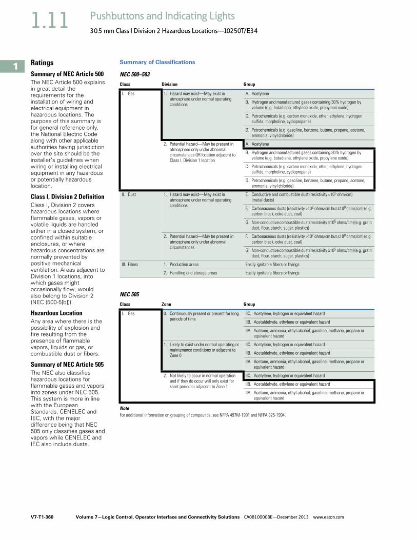
V7-T1-360 Volume 7—Logic Control, Operator Interface and Connectivity Solutions CA08100008E—December 2013 www.eaton.com
1
1
1
1
1
1
1
1
1
1
1
1
1
1
1
1
1
1
1
1
1
1
1
1
1
1
1
1
1
1
1.11 Pushbuttons and Indicating Lights
30.5 mm Class I Division 2 Hazardous Locations—10250T/E34
RatingsSummary of NEC Article 500The NEC Article 500 explains in great detail the requirements for the installation of wiring and electrical equipment in hazardous locations. The purpose of this summary is for general reference only, the National Electric Code along with other applicable authorities having jurisdiction over the site should be the installer’s guidelines when wiring or installing electrical equipment in any hazardous or potentially hazardous location.
Class I, Division 2 DefinitionClass I, Division 2 covers hazardous locations where flammable gases, vapors or volatile liquids are handled either in a closed system, or confined within suitable enclosures, or where hazardous concentrations are normally prevented by positive mechanical ventilation. Areas adjacent to Division 1 locations, into which gases might occasionally flow, would also belong to Division 2 (NEC (500-5[b])).
Hazardous LocationAny area where there is the possibility of explosion and fire resulting from the presence of flammable vapors, liquids or gas, or combustible dust or fibers.
Summary of NEC Article 505The NEC also classifies hazardous locations for flammable gases and vapors into zones under NEC 505. This system is more in line with the European Standards, CENELEC and IEC, with the major difference being that NEC 505 only classifies gases and vapors while CENELEC and IEC also include dusts.
Summary of Classifications
NEC 500–503
NEC 505
NoteFor additional information on grouping of compounds, see NFPA 497M-1991 and NFPA 325-1994.
Class Division Group
I. Gas 1. Hazard may exist—May exist in atmosphere under normal operating conditions
A. Acetylene
B. Hydrogen and manufactured gases containing 30% hydrogen by volume (e.g. butadiene, ethylene oxide, propylene oxide)
C. Petrochemicals (e.g. carbon monoxide, ether, ethylene, hydrogen sulfide, morpholine, cyclopropane)
D. Petrochemicals (e.g. gasoline, benzene, butane, propane, acetone, ammonia, vinyl chloride)
2. Potential hazard—May be present in atmosphere only under abnormal circumstances OR location adjacent to Class I, Division 1 location
A. Acetylene
B. Hydrogen and manufactured gases containing 30% hydrogen by volume (e.g. butadiene, ethylene oxide, propylene oxide)
C. Petrochemicals (e.g. carbon monoxide, ether, ethylene, hydrogen sulfide, morpholine, cyclopropane)
D. Petrochemicals (e.g. gasoline, benzene, butane, propane, acetone, ammonia, vinyl chloride)
II. Dust 1. Hazard may exist—May exist in atmosphere under normal operating conditions
E. Conductive and combustible dust (resistivity <105 ohm/cm) (metal dusts)
F. Carbonaceous dusts (resistivity >102 ohms/cm but <108 ohms/cm) (e.g. carbon black, coke dust, coal)
G. Non-conductive combustible dust (resistivity >105 ohms/cm) (e.g. grain dust, flour, starch, sugar, plastics)
2. Potential hazard—May be present in atmosphere only under abnormal circumstances
F. Carbonaceous dusts (resistivity >102 ohms/cm but <108 ohms/cm) (e.g. carbon black, coke dust, coal)
G. Non-conductive combustible dust (resistivity >105 ohms/cm) (e.g. grain dust, flour, starch, sugar, plastics)
III. Fibers 1. Production areas Easily ignitable fibers or flyings
2. Handling and storage areas Easily ignitable fibers or flyings
Class Zone Group
I. Gas 0. Continuously present or present for long periods of time
IIC. Acetylene, hydrogen or equivalent hazard
IIB. Acetaldehyde, ethylene or equivalent hazard
IIA. Acetone, ammonia, ethyl alcohol, gasoline, methane, propane or equivalent hazard
IIC. Acetylene, hydrogen or equivalent hazard1. Likely to exist under normal operating or maintenance conditions or adjacent to Zone 0 IIB. Acetaldehyde, ethylene or equivalent hazard
IIA. Acetone, ammonia, ethyl alcohol, gasoline, methane, propane or equivalent hazard
2. Not likely to occur in normal operation and if they do occur will only exist for short period or adjacent to Zone 1
IIC. Acetylene, hydrogen or equivalent hazard
IIB. Acetaldehyde, ethylene or equivalent hazard
IIA. Acetone, ammonia, ethyl alcohol, gasoline, methane, propane or equivalent hazard

Volume 7—Logic Control, Operator Interface and Connectivity Solutions CA08100008E—December 2013 www.eaton.com V7-T1-361
1
1
1
1
1
1
1
1
1
1
1
1
1
1
1
1
1
1
1
1
1
1
1
1
1
1
1
1
1
1
1.11Pushbuttons and Indicating Lights
30.5 mm Class I Division 2 Hazardous Locations—10250T/E34
Summary of Basic Methods Available for Class I, Division 2 Locations
Factory Sealed Contact Blocks Hermetically Sealed Reed Contact Block
Explosion Proof Enclosure
MethodFeaturesConfiguration Advantages Disadvantages
Factory sealed contact block Closed-ended labyrinth contact block with an incendive circuit incapable of external ignition
Higher continuous carrying amperages—up to 10A
Direct drive contacts—contacts can be forced open
Suitable for use in all enclosures
Best suited for motor control applications
May not be suitable for logic level circuits
Hermetically sealed block Reed switch sealed against an external atmosphere
Suitable for low energy level circuits
Suitable for use in all enclosures
Lower continuous carrying amperages are not suitable for motor control applications(typically 3A to 5A rated)
Contacts cannot be forced open
Permanent magnet attracts metallic dust and filings that can reduce the electrical creepage distance between live terminals
Explosion proof enclosures (Class I, Division 1 and 2)
Enclosures capable of withstanding an internal explosion while preventing external ignition. Enclosures designed for Class I, Division 1 can safely be used in Class I, Division 2
Higher level of protection than required for Class I Division 2
Higher material and installation costs
Conduit sealing is still required
Time consuming maintenance
Direct Drive ContactsContacts can be mechanically forcedapart if subject to anarch/fault current.
CooledEscaping
Gas
InternalIgnition
•
Hermetically sealedreed does not allowexternal atmosphere to enter switching chamber.
Depression of plunger rotates magnet and either opens/closes contacts.Contacts can not be forced apart if subject to arch/fault current, because no mechanical connection exists.
CooledEscaping
Gas
Threaded Joint Flat Joint
InternalIgnition Internal
Ignition CooledEscaping
Gas


