
Vanguard Applications WareBasic Protocols
Configuring with PAD/ATPAD

Notice
©2008 Vanguard Networks 25 Forbes Blvd Foxboro, MA 02035 Phone: (508) 964 6200 Fax: (508) 543 0237 All rights reservedPrinted in U.S.A.
Restricted Rights Notification for U.S. Government Users
The software (including firmware) addressed in this manual is provided to the U.S. Government under agreement which grants the government the minimum “restricted rights” in the software, as defined in the Federal Acquisition Regulation (FAR) or the Defense Federal Acquisition Regulation Supplement (DFARS), whichever is applicable.
If the software is procured for use by the Department of Defense, the following legend applies:
Restricted Rights LegendUse, duplication, or disclosure by the Government
is subject to restrictions as set forth in subparagraph (c)(1)(ii) of the
Rights in Technical Data and Computer Software clause at DFARS 252.227-7013.
If the software is procured for use by any U.S. Government entity other than the Department of Defense, the following notice applies:
NoticeNotwithstanding any other lease or license agreement that may pertain to, or accompany the delivery of, this computer software, the rights of the Government regarding its use, reproduction, and disclosure are as set forth in FAR 52.227-19(C).
Unpublished - rights reserved under the copyright laws of the United States.

Notice (continued)
Proprietary Material
Information and software in this document are proprietary to Vanguard Managed Solutions (or its Suppliers) and without the express prior permission of an officer of VanguardMS, may not be copied, reproduced, disclosed to others, published, or used, in whole or in part, for any purpose other than that for which it is being made available. Use of software described in this document is subject to the terms and conditions of the Vanguard Managed Solutions Software License Agreement.
This document is for information purposes only and is subject to change without notice.
To comment on this manual, please send e-mail to [email protected]
Part No. T0110, Rev JPublication Code TKFirst Printing November 1998
This manual is current for Release 7.3 of Vanguard Applications Ware.


Contents
i
About Packet Assembler/Disassembler......................................................... 2Applications................................................................................................... 3PAD Port Configuration ................................................................................ 6
PAD Port Record Parameters .................................................................... 8PAD Port Configuration for Autocalling .................................................. 22PAD Port Configuration for Autospeed .................................................... 24PAD XON/OFF Support Using X.25 Interrupt Packets............................ 25
PAD Prompt Table Record ............................................................................ 26PAD Prompt Table Record Parameters ..................................................... 27
PAD Profile Table Record ............................................................................. 28PAD Profile Table Record Parameters ...................................................... 30Copying PAD Profile Tables into a Configuration.................................... 44
Remote PAD Parameter Table Record .......................................................... 49Remote PAD Parameter Table Record Parameters ................................... 50
Detailed PAD Port Statistics .......................................................................... 53ATPAD Ports ................................................................................................. 56
ATPAD Operation ..................................................................................... 56ATPAD Port Record Parameters ............................................................... 60ATPAD Port Statistics ............................................................................... 69


PAD/ATPAD Ports 1
PAD/ATPAD Ports
Overview
Introduction This manual describes the PAD and ATPAD port configurations for Vanguard products. It includes explanations of both PAD port types, commands that can be used, and how to configure a node for either PAD or ATPAD operation.
Before You Begin Before you can configure parameters, you must log on to the local node’s control terminal port. Refer to the Vanguard Configuration Basics Manual for CTP procedures.
In This Manual Topic See Page
About Packet Assembler/Disassembler......................................................... 2Applications................................................................................................... 3PAD Port Configuration ................................................................................ 6
PAD Port Record Parameters .................................................................... 8PAD Port Configuration for Autocalling .................................................. 22PAD Port Configuration for Autospeed .................................................... 24PAD XON/OFF Support Using X.25 Interrupt Packets............................ 25
PAD Prompt Table Record ............................................................................ 26PAD Prompt Table Record Parameters ..................................................... 27
PAD Profile Table Record ............................................................................. 28PAD Profile Table Record Parameters ...................................................... 30Copying PAD Profile Tables into a Configuration.................................... 44
Remote PAD Parameter Table Record .......................................................... 49Remote PAD Parameter Table Record Parameters ................................... 50
Detailed PAD Port Statistics .......................................................................... 53ATPAD Ports ................................................................................................. 56
ATPAD Operation ..................................................................................... 56ATPAD Port Record Parameters ............................................................... 60ATPAD Port Statistics ............................................................................... 69

2 PAD/ATPAD Ports
About Packet Assembler/Disassembler
About Packet Assembler/Disassembler
What is a PAD? A Packet Assembler/Disassembler (PAD) provides network access and ensures compatibility between different hosts and terminals and a packet switched network. A PAD does this by packetizing data (Assembling) sent to the PAD from a terminal device, and then routing that packetized data through a packet switching node and onto the network.
A PAD can also de-packetize (Disassemble) data it receives from the network before it is sent to the destination (host or terminal).
What Is a PAD Port?
A PAD port lets you transmit asynchronous data. When setting the Port Type to PAD, the remainder of the Port Record contains only those parameters needed for configuring the PAD port.
In this record, you can configure a PAD port for the following:
• Autocalling• Autospeed• Address blanking
What is an ATPAD The ATPAD is an asynchronous port that lets you make and clear X.25 calls using a restricted set of Hayes AT commands.
Features PAD ports provide these features:
• A set of commands to make and clear calls• A set of response codes that indicate the generation condition• Other features such as configurable control characters, data forwarding
criteria, and answer mode for tailoring the ATPAD to your application • Support for network parity, response delay, and DTR timeout• Configurable Escape Sequence Timer• Automatic or manual answer• Four stored X.25 addresses (mnemonics) accessible by the ATDSn command• Control signal or XON/XOFF flow control• Configuration of operating parameters via the CTP

PAD/ATPAD Ports 3
T0110, Revision J Release 7.3
Applications
Applications
Introduction This section explains how PAD ports are used. It describes a typical application as well as an application where MBC protocol is supported on Vanguard 6560s.
Typical PAD Application
Figure 1 shows the use of modems in an application. It also shows how a Vanguard with the PAD port replaces the modems and concentrates mixed data types on a single access line. A PC runs purchased script files that use AT commands.
Figure 1. Topologies With and Without the PAD
NoteYou can access the PAD with PC scripts. The PC scripts use AT commands to make calls through an X.25 network.
Before PAD
PC
AT Modem
Other Devices
Other Dedicated Modems/Lines
Single Access Line
With PAD
PC
Other Devices
Vanguard

4 PAD/ATPAD Ports
Applications
MBC Protocol on 6560s
The MBC Protocol is used in banking networks where multiple branch offices are connected to the central site office through a Frame Relay network (with ISDN backup). The MBC Protocol is supported on Vanguard 6560s.
To understand how MBC Protocol support can be used, consider the examples shown in Figures 2 and 3 where Vanguard 6560s connect an IBM host to the Frame Relay network.
In Figure 2 the branch office uses a Vanguard 6520 to connect its polling controller equipment (BP) to the Frame Relay network. The 6520 runs the SDLC protocol on the line to the BP. The BP in turn connects to a line controller called the MBC which is connected to multiple devices (ATM machines, cash dispensers, and terminals). The MBC protocol runs between the BP and the devices.
Figure 2. With MBC Support on 6560
Figure 3 shows a network where the branch office does not have a BP polling controller. Instead the BP reside at the central site. In this example, the MBC protocol frames need to be transported across the Frame Relay network using a 6560 that supports the MBC protocol.
MBC
ATMs/ Terminals
Frame RelayNetwork6560 6520
ISDN
Central Site Office Branch Office
IBM Host
FRI FRI SDLC BP MBC

PAD/ATPAD Ports 5
T0110, Revision J Release 7.3
Applications
Figure 3. MBC Protocol Support on 6560
Configuring 6560 for MBC ProtocolTo configure a 6560 for MBC support you must go to the PAD Port Record and the PAD Profile Table and set these parameters to the following values:
NoteThe table lists only those parameters that effect the MBC Protocol. Other PAD Port and PAD Profile parameters must be set as part of the configuration process.
MBC
BPATMs/ Terminals
Frame RelayNetwork6560 6520 V320
ISDN
Central Site Office Branch Office
IBM Host
MBC
FRI FRI MBC
Parameter Value
PAD Port Record Parameters
Port Speed 9600 or 19200 (depending on the terminal)
Call Control Auto
Terminal Control Hennis
Autocall Mnemonic the mnemonic mapped to the remote PAD port
Inter-Character Timeout 0 (This parameter appears only when Terminal Control = Hennis.)
PAD Profile Table
Dynamic Data Forwarding 1
PAD Mode • 1 (on PADs attached to the BP)• 2 (on PAD attached to MBC)

6 PAD/ATPAD Ports
PAD Port Configuration
PAD Port Configuration
Introduction To configure a PAD port, you must first access the CTP on your Vanguard device.
NoteRefer to the Vanguard Configuration Basics Manual for CTP procedures.
PAD Port Configuration Record
Figure 4 shows the PAD port configuration parameters.
Figure 4. PAD Port Record
Node: Address: Date: Time: Menu: Configure Path: (Main.6)
NodePort
Port Name
*Port Number
*Port Type
PAD
Connection TypePort ControlPort SpeedAuto Baud SequenceData Bits Per CharacterDevice ParityNumber of Stop BitsProfile NameCall ControlTerminal ControlPAD Prompt Entry NumberRemote PAD Parameters Number Autocall MnemonicAutocall TimeoutMaximum Number of Autocall AttemptsSubaddress
Group SubaddressCUG MembershipBilling RecordsInvitation to ClearCall Attempt Timeout*Protection Level (DCP Only)Reconnection Timeout (DCP Only)Reconnection Tries Limit (DCP Only)Maximum Receive Buffer LengthPAD COmmand LanguageNUI Facility FormatVUI verification timerMax NUI violationsAction Type for NUI violationsInter-Character Time-out

PAD/ATPAD Ports 7
T0110, Revision J Release 7.3
PAD Port Configuration
Guidelines Follow these guidelines for configuring other PAD port parameter:
Other Tables You Must Configure
If your port type is PAD Port, you must also configure parameters in these tables:
• PAD Profile Table (see “PAD Profile Table Record” section on page 28)• PAD Prompt Table (see “PAD Prompt Table Record” section on page 26)
Accessing the Record
Follow these steps to access the PAD Port Record:
If You Specify or Set... Then...
Profile Name The entry must exist in the PAD Profile Table.
Call Control to AUTO or AUTC Autocall Mnemonic must have a value.
Call Control = AUTO and (Port Record) Connection Type = SIMP,
Maximum Number of Autocall Attempts must be 0.
Ports as having Call Control = AUTO
Configure each port to have different values for Autocall Timeout.
Terminal Control to PASS An NUI Table entry must exist.
Terminal Control to CUG An entry for CUG Membership must exist.
PAD Prompt Entry Number The entry must exist in the PAD Prompt table.
Remote PAD Parameters Number The entry must exist in the Remote PAD Parameters Table.
Autocall Mnemonic The entry must exist in the Mnemonic Table.
A Subaddress value It should equal the port number.
Billing Records as On A Billing Printer Mnemonic must be specified in the Mnemonic Table.
Step Action Result
1 Select Configure from the CTP Main menu.
The Configure menu appears.
2 Select Port from the Configure menu and configure the Port Number in the Port Record.
The prompt for the Port Number appears
3 Enter port type: PAD The first parameter for PAD Port Type appears, as shown in Figure 4.
4 Enter each parameter value and save the record. Press <ESC> to return to the Configure menu.

8 PAD/ATPAD Ports
PAD Port Configuration
PAD Port Record Parameters
Introduction This section describes the PAD port parameters. Any parameter with an asterisk (*) requires a Node boot.
NoteIf you have enabled Ease of Configuration, you need to boot only the port to make changes to the parameters marked with an asterisk. For more information, refer to the Ease of Configuration section in the introductory portion of the Basic Protocols Manual, (Part Number T0106).
Parameters These are the port parameters when Port Type is set to PAD:
*Port Type
Range: NULL, PAD, ATPAD, X25
Default: PAD
Description: Specifies the port type.• NULL: NULL port• PAD: PAD port• ATPAD: ATPAD port• X25: X.25 port
Connection Type
Range: SIMP, DTR, DTRD, DTRP, DIMO, DIMOa, DIMOb, EMRI, EMDC, EMCDIO
Default: SIMP
Description: Specifies the type of control signal handshaking that is required before logical connections can be made to this port. See the table below for information about when to use a connection type.
Use Connection Type When...
SIMP (Simple) A terminal is wired to the port with a cable that has a minimum of conductors (so most control signals are missing). Such cabling provides only ground, transmit, and receive data. Control signals from the port are maintained high. If data restraint by control signal is enabled, the CTS lead changes as required.
DTR The device connected to the port provides DTR to maintain the EIA connection. Remote users calling the device through a PAD port know if the device is disconnected or powered down, because the call is not completed.

PAD/ATPAD Ports 9
T0110, Revision J Release 7.3
PAD Port Configuration
DTRD DTR signal required. DCD, DSR, CTS drop for 1 second between calls and then return to idle state. During the control signal drop, the port is unable to receive calls.
DTRP • DTR is passed end-to-end. • Port raises CTS and DCD when it raises DSR.
The port does not monitor RTS.• EIA Monitor supports DTRP. • DTRP doesn’t support PVC connections.• Configure PAD ports as an answer/originate pair
by selecting auto calling on the originate end. • Supports primary handshaking only (DTR/DSR)
and should not be used with tail circuit modems.
DIMO A crossover cable attaches a dial modem to the port, and whose handshake uses modem control signals as calls are made. These are the types of DIMO operation:
• Dial In: Calls received from the telephone network.
• Dial Out: Calls received from the port.• Dial In/Dial Out Collision: Calls received
simultaneously from the telephone network and the port.
DIMOa Same as DIMO but DSR is not raised on incoming calls.
DIMOb Same as DIMO but DSR follows DTR on incoming calls.
EMRI A port connects to a host computer and replaces a modem. The port emulates a dial modem with Ring Indicator (RI).
EMDC A port connects to a host computer and replaces a modem. The port emulates a dial modem with Data Carrier Detect (DCD) used to signal an incoming call.
EMCDIO A port connects to an asynchronous host computer and emulates a modem with DCD for incoming and outgoing calls.
Use Connection Type When... (continued)

10 PAD/ATPAD Ports
PAD Port Configuration
Port Control
Range: NONE, MB
Default: NONE
Description: • MB: Enables the make-busy feature for the specified port; disabling the port raises pin 22 only when Connection Type = DIMO, DIMOa, DIMOb, DTR, DTRD, or SIMP.
• NONE: Disables this parameter.
Port Speed
Range: 50, 75, 100, 110, 134, 150, 200, 300, 600, 1200, 1800, 2400, 4800, 7200, 9600, 14400, 19200, 28800, 38400, 75/1200, AUTO
Default: 9600
Description: Specifies the port speed in bits per second. • Port speed is set by this parameter although the PAD Profile
Table can specify a PAD port's characteristics. • When 134 is selected, the actual speed is 134.5 bps.• Split speed (75/1200) can be configured only on 6500PLUS
Processor and Asynchronous I/O Cards.

PAD/ATPAD Ports 11
T0110, Revision J Release 7.3
PAD Port Configuration
Auto Baud Sequence
Range: CR_ONLY, CR_DOT_CR, TYMNET, TELENET
Default: CR_ONLY
Description: Specifies these character sequences used for autospeed recognition:
• CR_Only: Autospeed on <CR>• CR_DOT_CR: Autospeed on <CR>.<CR>• TYMNET: Autospeed on the letter “a” (must be lower case)• TELENET: Autospeed on <CR><CR> for 1200 bps or lower
and @ <CR> for 2400 bps or higher• DOT_DOT_CR: autospeed on two or three dots followed by
<CR>• SP_P_CR: autospeed on " P<CR>"
This parameter only impacts autospeed PAD ports with the following configuration settings:
• Port Speed = AUTO • Device Parity = Auto • Data Bits Per Character = 7
The speeds are supported on the 6500PLUS, Vanguard 6520, and Vanguard platforms. The autospeeds of 14.4 Kbps, 19.2 Kbps, 28.8 Kbps, and 38.4 Kbps are not supported on UIO/AIO cards.
• Used to detect and adapt to the speed and parity of a terminal configured as 7 bit plus parity.
• Select CR_DOT_CR if the connecting terminal's Data Bits per Character (7 or 8) is unknown or changes (typical for dial-in applications).

12 PAD/ATPAD Ports
PAD Port Configuration
Data Bits per Character
Range: 5 to 8
Default: 8
Description: Sets the bits per character. This value must match the number of bits per character used by the attached device.
Device Parity
Range: NONE, SPAC, MARK, EVEN, ODD, AUTO
Default: NONE
Description: Specifies the type of parity the PAD port generates and returns from the attached device:
• NONE: With 7-bit data or when the data is 7 bits with parity, and the parity bit is passed to the remote end as the eighth bit.
• SPAC: Space parity.• MARK: Mark parity.• EVEN: Even parity.• ODD: Odd parity.• AUTO: When the port is configured for autospeed, this sup-
ports 7 bits odd, 7 bits even, and 7 bits ignore.• AUTOA: When the port is configured for autospeed, this sup-
ports 7 bits odd, 7 bits even, and 8 bits none.
Number of Stop Bits
Range: 1, 1.5, 2
Default: 1
Description: Specifies the number of Stop Bits that the PAD port generates when it sends data to the attached device. This parameter has no effect on data received from the attached device.
Profile Name
Range: 0 to 8 alphanumeric characters
Default: 0
Description: The name of the PAD Profile Table used by this port. Choose from one of the names in PAD Profile Table or 12 Default Profiles.

PAD/ATPAD Ports 13
T0110, Revision J Release 7.3
PAD Port Configuration
Call Control
Range: NONE, AUTO, AUTC, PCUD, IBAR, OBAR, MNEM, TMNEM, EMNEM
Default: NONE
Description: Specifies PAD behavior and limitations when making and receiving calls:
• NONE: No options• AUTO: Automatically places a call when an EIA connection
is established• AUTC: Automatically places a call when <CR> is received• PCUD: Pass Call User Data (CUD) to user profile for no
service signals• IBAR: Bar calls inbound from PAD user• OBAR: Bar calls outbound to PAD user• MNEM: Place only mnemonic calls• EMNEM: allow extended mnemonic call (without dot)• TMNEM: Call mnemonic (maximum 16 alphanumeric
characters) that is not resolved in the local node. This option cannot be summed with any of the above options.
These events occur when you sum AUTO+IBAR+PCUD:• Automatic calling is in effect.• Call User Data passes from the user with no service signals.• Incoming calls are not accepted by that user.
NoteDo not sum IBAR and OBAR because, when combined, they render the port useless.

14 PAD/ATPAD Ports
PAD Port Configuration
Terminal Control
Range: NONE, PASS, LIM, CUG, LCPY, 7BIT, NADD, X.28, CNUI, CUGOA, BMSG, ADDR, FRCB, CUGIA, HENNIS
Default: NONE
Description: Specifies options for the attached device:• NONE: No option specified• PASS: A password is required (configured in the NUI/
Password Table).• DNP1: Support DATAPAC 3101 compatible prompts.• LIM: X.28 mode is limited to CALL and CLR commands.• CUG: Check Closed User Group (CUG); otherwise the CUG
passes transparently.• LCPY: Allow local copying to this PAD port• 7BIT: Allows an internal 7-bit representation of characters to
determine if extra processing is needed. – Example: The line delete character is hexadecimal value
18, and the input character received by the PAD is hexadecimal 98. If 7BIT is not selected, the current input line is not deleted. If 7BIT is selected, the input line is deleted as the internal representation of the character would only be 7 bits.
• NADD: Prevents PAD port from receiving calling address and facility’s service signals
• X28: Automatically returns from X.28 mode to PAD mode after sending the X.28 commands
• CNUI: Provides Centralized Network User Identification verification.
• CUGOA: Subscribe to Closed User Group with Outgoing Access.
• BMSG: Displays the PAD Bulletin/Banner Message.• ADDR: The calling address is not shown.• FRCB: Connects to a French Cartes Bancaires (banking card)
device.• CUGIA: Checks the CUG but allows incoming access;
otherwise CUG data is passed transparently.• HENNIS: Allows MBC Protocol support on 6560.
NoteUse summing to combine several parameter values. CUGOA and CUG or CUG and CUGIA cannot be used together.

PAD/ATPAD Ports 15
T0110, Revision J Release 7.3
PAD Port Configuration
PAD Prompt Entry Number
Range: 0 to 8
Default: 0
Description: Specifies the customized prompt from the PAD Prompt Table. This parameter is ignored when Terminal Control = PASS and the PAD Prompt Entry Number is taken from the NUI/Password Table entry.
Remote PAD Parameters Number
Range: 0 to 6
Default: 0
Description: Specifies the Remote PAD Parameter Table entry number that is used by the remote PAD to update its X.3 characteristics when connected to this port. No updates are sent if this parameter is set to zero (0).
Autocall Mnemonic
Range: 0 to 8 alphanumeric characters
Default: N/A
Description: The mnemonic name that is used when the port is configured for autocalling.
NoteA corresponding entry must be made in the Mnemonic Table.
Autocall Timeout (sec)
Range: 5 to 255
Default: 10
Description: Specifies the time (in seconds) between call attempts when autocalling.
Autocall Timeout (sec)
Range: 5 to 255
Default: 10
Description: Specifies the time (in seconds) between call attempts when autocalling.

16 PAD/ATPAD Ports
PAD Port Configuration
Maximum Number of Autocall Attempts
Range: 0 to 255
Default: 4
Description: Specifies the number of times the PAD port attempts to call when autocalling is enabled. When the limit is reached, the port stops attempting to make a call. For unlimited call attempts, set to 0.
Subaddress
Range: 0 to 3 digits
Default: port #
Description: Specifies the subaddress for this PAD port. Incoming calls from the network with a network address consisting of the Node Address specified in the Node Record and this subaddress, arrive at this PAD port.
Group Subaddress
Range: 0 to 3 digits
Default: 00
Description: Specifies a port subaddress that several PAD ports share. Incoming calls with this subaddress are routed to one of several ports sharing this subaddress. To disable this parameter, set to (blank). Use the space bar to blank the parameter value.
CUG Membership
Range: 0 to 8 two-digit numbers
Default: --,--,--,--,--,--,--,--
Description: Specifies a port’s membership in up to 8 Closed User Groups (CUGs).
• Each CUG membership must be a two-digit number (00 to 99), separated from other groups by a comma.
• To delete a CUG, press the minus key twice for each group.
PAD/ATPAD Ports 17
T0110, Revision J Release 7.3
PAD Port Configuration
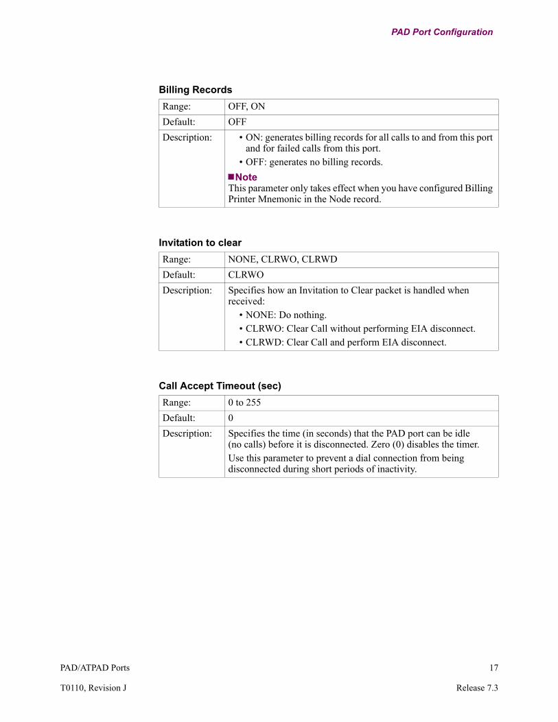
Billing Records
Range: OFF, ON
Default: OFF
Description: • ON: generates billing records for all calls to and from this port and for failed calls from this port.
• OFF: generates no billing records.
NoteThis parameter only takes effect when you have configured Billing Printer Mnemonic in the Node record.
Invitation to clear
Range: NONE, CLRWO, CLRWD
Default: CLRWO
Description: Specifies how an Invitation to Clear packet is handled when received:
• NONE: Do nothing.• CLRWO: Clear Call without performing EIA disconnect.• CLRWD: Clear Call and perform EIA disconnect.
Call Accept Timeout (sec)
Range: 0 to 255
Default: 0
Description: Specifies the time (in seconds) that the PAD port can be idle (no calls) before it is disconnected. Zero (0) disables the timer. Use this parameter to prevent a dial connection from being disconnected during short periods of inactivity.

18 PAD/ATPAD Ports
PAD Port Configuration
*Protection Level
Range: NONE, CP_ONLY, FULL_DCP
Default: NONE
Description: Specifies how Data Connection Protection is implemented for this port:
• NONE: The feature is turned off.• CP_ONLY: Connection protection only.• FULL_DCP: Full data and connection protection.
Valid only when the Data Connection Protection Option has been purchased for this node.
NoteChanges to this parameter require a Node boot to take effect.
Reconnection Timeout
Range: 1 to 128
Default: 2
Description: Specifies how long (in seconds) the Data Connection Protection feature waits between reconnection attempts. The call originator determines the value. If symmetric operation is required, the Reconnection Timeout and the Reconnection Tries limit should be equal.Valid only when the Data Connection Protection Option has been purchased for this node.
Reconnection Tries Limit
Range: 0 to 127
Default: 4
Description: Specifies the number of times that the Data Connection Protection feature attempts to reconnect before clearing the call. The call originator determines the value.If 0 is entered, there is no attempt to reconnect. If symmetric operation is required, the Reconnection Timeout and the Reconnection Tries limit should be equal.Valid only when the Data Connection Protection Option has been purchased for this node.

PAD/ATPAD Ports 19
T0110, Revision J Release 7.3
PAD Port Configuration
Maximum Receive Buffer Length
Range: 1 to 128 (2000 with TPA 2K Frame Size CSK enabled)
Default: 128
Description: Specifies the number of characters received by the driver before forwarding the packet.
NoteIf a port is configured as Transparent Polled Async PAD and CSK for TPA 2K Frame Size is enabled, the maximum frame size for this parameter is automatically set to 2K.
Called DTE Address
Range: 0 to 15 decimal digits
Default: 00000000
Description: Specifies the Called DTE Address for packets with call mnemonic.
NoteUse the space character to blank the field.
Calling DTE Identifier
Range: 0 to 8 alphanumeric characters
Default: (blank)
Description: Specifies the Calling DTE Identifier for packets with call mnemonic.
NoteUse the space character to blank the field.
Calling DTE Password
Range: 0 to 8 alphanumeric characters.
Default: (blank)
Description: Specifies the Calling DTE Password for packets with call mnemonic.
NoteUse the space character to blank the field.

20 PAD/ATPAD Ports
PAD Port Configuration
PAD Command Language
Range: CCITT, DPN
Default: CCITT
Description: Specifies the language used for PAD commands.• CCITT: X.28 CCITT• DPN: DPN ITI
NUI Facility Format
Range: ODPN, NDPN, 1992_DPN
Default: ODPN
Description: Specifies the NUI facility field format.• ODPN: Old DPN format• NDPN: New DPN format• 1992_DPN: S1992 NUI format
NUI verification timer
Range: 5 to 180
Default: 60
Description: Specifies the time (in seconds) that time waits before the call is cleared.
Max NUI violations
Range: 0 to 10
Default: 3
Description: The maximum number of successive NUI verification failures that can be tolerated when making verification attempts through a PAD port.
NoteRefer to the “Action Type for NUI violations” if the Max NUI Violations are reached.

PAD/ATPAD Ports 21
T0110, Revision J Release 7.3
PAD Port Configuration
Action Type for NUI violations
Range: NONE, DISC, DEGR, LOCK
Default: NONE
Description: This specifies the action to be taken if the NUI violations exceed the configured threshold count.
• NONE: No action is taken.• DISC: The port is disconnected.• DEGR: The port is busied-out for one minute and then is
re-enabled.• LOCK: The port is disabled and operator intervention is
required to enable the port.
NoteThis parameter is effective only when the parameter Port Control parameter is set to CNUI.
Inter-Character Time-out
Range: 0 to 5
Default: 0
Description: Specifies the maximum time (in 50-millisecond increments) between characters in a frame. When set to zero (0) this parameter is disabled.
NoteThis parameter only appears when the parameter Terminal Control is set to HENNIS.

22 PAD/ATPAD Ports
PAD Port Configuration
PAD Port Configuration for Autocalling
Introduction You must configure several parameters in the PAD port record for autocalling.
• Call Control (set to AUTO or AUTC)• Autocall Mnemonic (this must be defined in the Mnemonic Table)• Autocall Timeout (sec)• Maximum Number of Autocall Attempts
Initiating an AutoCall
An autocall is initiated in one of two ways.
• The terminal connects to the port (the parameters Call Control = AUTO and Connection Type is not SIMP). If the call attempt fails, the PAD initiates another call after a time specified in the parameter Autocall Timeout. The parameter Number of Autocall Tries specifies the number of times the PAD tries to make a connection. The PAD stops the process until the EIA input signals are lowered and then raised.
• A call is initiated when the terminal connects to the port and you press <CR> (Call Control = AUTC). If the call attempt fails, you must reenter <CR> to attempt another call.
Mnemonic Addressing
You can configure an autocall port to automatically place a call at power up and have it routed with a mnemonic. This is useful when you are limited to a single host application and are always calling the same address.
Autocalling uses the Vanguard products mnemonic addressing function. Keep in kind the following when configuring for Autocalling:
• A Mnemonic Table entry must have a corresponding Route Selection Table entry.
• The port initiating the call must be configured for Autocalling (Port Record parameter Call Control is set to AUTO or AUTC).- AUTO specifies that the call is attempted when the EIA handshake is
complete. When Connection Type = SIMP, autocalls are made on power up or port boot.
- AUTC specifies that the call is attempted when the EIA handshake is complete and a <CR> is entered.

PAD/ATPAD Ports 23
T0110, Revision J Release 7.3
PAD Port Configuration
SDLC Mnemonic Addressing
Calls placed in a port configured for SDLC must use the mnemonic calling feature.
Figure 5 shows the configuration process for calls on SDLC ports. Station 2, Port 4 in Node 100 is configured to call Station 3, Port 3 in Node 200.
Figure 5. SDLC Mnemonic Autocall Addressing
NoteThese configuration records and parameters pertain only to SDLC Mnemonic Autocall Addressing. There are also others that must be configured.
For details about SDLC, refer to the SDLC Option Manual (Part No. T0101-05).
6520 6520
Station 1
Station 2
Station 3
Station 1Station 2
Station 3
SLDCPort# 04
HPAD
SLDCPort# 3TPADNode 100
(Node Address 10000)Node 200
(Node Address 20000)
X25-4 X25-5
Port RecordPort Number: 4Port Type: SDLCSub Type: HPAD*
SDLC Station RecordPort Number: 4Station Number: 2Autocall Mnemonic: MnemonicStation Subaddress: 2
Mnemonic Table RecordMnemonic Name: MnemonicCall Parameters: 20000303
Route Selection Table Address=: 200Destination: X25-1Priority: 1
Port RecordPort Number: 3Port Type: SDLCSub Type: TPAD*
SDLC Station RecordPort Number: 3Station Number: 3Autocall Mnemonic: (Blank)Station Subaddress: 3
Route Selection Table Address=: 20003Destination: SDLC-3S3Priority: 1

24 PAD/ATPAD Ports
PAD Port Configuration
PAD Port Configuration for Autospeed
Introduction Autospeed is a convenient way to configure a PAD port's speed, especially when you want a mix of terminal speeds. For example, autospeed is useful when the PAD port is connected to a modem that is called by different devices with different speeds.
Implementing Autospeed
To implement autospeed, set the Port Record parameter Port Speed = AUTO. When the device calls the port, the port determines the speed of the device and programs its I/O drivers to match the device's speed.
Auto Baud Sequence Parameter
A related parameter that effects Autospeed is the Auto Baud Sequence (in the PAD Port Record). This parameter specifies the Autospeed Recognition Character that the port uses to set the correct speed. These are the settings available with the Auto Baud Sequence parameter:
• CR_Only: Autospeed on <CR> (default)• CR_DOT_CR: Autospeed on <CR>.<CR>• TYMNET: Autospeed on the letter “a” (must be lower case)• TELENET: Autospeed on <CR><CR> for 1200 bps or lower and @ <CR>
for 2400 bps or higher• DOT_DOT_CR: autospeed on two or three dots followed by <CR>• SP_P_CR: autospeed on "P<CR>"
The autobaud feature can support 14.4, 19.2, 28.8, and 38.4 kbps for all autospeed recognition characters. These speeds are not supported on the UIO or AIO cards.
Autospeed Inter-Character Delay
Inter-Character Delay is the transmission time interval between characters. For example, Figure 6 shows the autospeed inter-character delay applied to the CR_DOT_CR sequence presented above.
Figure 6. Autospeed Inter-Character Delay
Reduced Autospeed Inter-Character Delay
When using a dial modem with a POS terminal or PC to send an Autobaud Sequence, problems may occur if the inter-character delay applied to that sequence is less than 180 msec. To overcome this, you must enter a CSK (5ERWXW2F76XHLTTUUZC3) to reduce the inter-character processing time to 100 msec.
NoteReducing the autospeed inter-character delay also increases the minimum supported autospeed to 300 bps.
CR CR. (dot)
100msec
100msec
Autospeed Inter-Character Delay
Autospeed Inter-Character Delay

PAD/ATPAD Ports 25
T0110, Revision J Release 7.3
PAD Port Configuration
PAD XON/OFF Support Using X.25 Interrupt Packets
What is It? There is a Customer Software Key (CSK) that enables the transmission of XON/XOFF asynchronous data characters across a Public Data Network (PDN) using X.25 Interrupt packets.
This improves the transmission of flow control information between local and remote PAD ports on Vanguard internetworking devices. Since X.25 Interrupt packets travel at a higher priority through the PDN, flow control information between PAD ports is communicated more thoroughly when you control the starting and stopping of the asynchronous data characters stream.
How It Works When a Vanguard PAD port receives an XON or XOFF flow control character from a user terminal or networking device, this feature sends the flow control characters across the PDN as X.25 Interrupt packets.
Consider the example shown in Figure 7. To stop User 2 from sending information, User 1 sends an XOFF character to the PAD port on the local Vanguard. Then the local Vanguard sends an X.25 Interrupt Packet to the remote node on the other side of the network, where the XOFF character is passed on to User 2. This stops User 2 from sending anymore data.
To let User 2 send information, User 1 sends an XON character into the PAD port on the local Vanguard, which sends an X.25 Interrupt Packet to the other node. Tthe XON character is passed on to User 2. This allows User 2 to send data again.
Figure 7. Transmitting XON/OFF Frames with X.25 Interrupt Packets
The User devices in Figure 7 can be networking devices or asynchronous terminals.
For this feature to work, user devices at both ends of the network must be connected to Vanguard devices. In addition, set the PAD Profile record parameters Device Flow Control and PAD Data Restraint to 1 for both PAD ports.
To enable this CSK Complete these steps to enable the XON/XOFF CSK:
PDN
Vanguard
User 1 User 2
PAD Port PAD Port
X.25 ports
X.25 VC Vanguard
Step Action
1 From the CTP Main menu, select Configure.
2 From the Configure menu, select Software Key Table.
3 Press <CR> (to access the Key Value field) and type the CSK number: BGMV4HE3EGJCRFETYKH3
4 To implement the feature, boot the node.

26 PAD/ATPAD Ports
PAD Prompt Table Record
PAD Prompt Table Record
Introduction You can change the PAD prompt which appears when a terminal connects to a Vanguard node and is in Command Mode. The default prompt is an asterisk (*). You use the PAD Prompt Table to change the parameter.
NoteBefore you can configure parameters, you must log on to the local node’s control terminal port.
What You See in This Record
Figure 8 shows how the PAD Prompt Table Record and its configuration parameters fit into the Vanguard products menu hierarchy.
Figure 8. PAD Prompt Table Record
Accessing the PAD Prompt Table Record
Follow these steps to access the PAD Prompt Table record:
Entry NumberPAD Prompt Text
Node: Address: Date: Time: Menu: Configure Path: (Main.6)
NodePortSoftware Key TableInbound Call Translation TableOutbound Call Translation TablePAD Prompt Table
Step Action Result
1 Select Configure from the CTP Main menu.
The Configure menu appears.
2 Select PAD Prompt Table from the Configure menu.
The PAD Prompt Table and its parameters appear.A prompt appears asking you to configure the next parameter.
3 Enter the parameter values.
4 Press <ESC> to return to the Configure menu after you have configured all parameters.

PAD/ATPAD Ports 27
T0110, Revision J Release 7.3
PAD Prompt Table Record
PAD Prompt Table Record Parameters
Introduction This section describes the PAD Prompt Table parameters.
Parameters From the PAD Prompt Table Record, you can configure these parameters (with the exception of Entry Number):
Entry Number
Range: 1 to 8
Default: 1
Description: Identifies the particular PAD Prompt Table entry being configured by the other parameter in the record. This parameter is not configurable.
PAD Prompt Text
Range: 0 to 1023 alphanumeric characters
Default: N/A
Description: This text appears in place of the default PAD prompt asterisk (*). Enter the PAD prompt as a series of ASCII characters, terminated by a <CR>. Use these special characters to display information about the PAD Prompt text. If the character following the (%) symbol is not a special character, both the (%) and these character are discarded.
• A: Node address• C: Channel number• G: Group subaddress• N: Node name• P: Port number• S: Subaddress• T: Time• V: Software revision
Enter the caret (^^) twice (it is discarded otherwise) as an escape character to tell the PAD to send control characters. The character following the caret is converted to a control character and is sent to the PAD port for output.

28 PAD/ATPAD Ports
PAD Profile Table Record
PAD Profile Table Record
Introduction The PAD Profile Table Record specifies the profile for a single PAD Port, in the local node. Many other PAD ports can also use the same PAD Profile Table Record to ensure that all PAD Ports have the same characteristics. You can configure up to 16 PAD profiles.
What You See In This Record
Figure 9 shows how the PAD Profile Table Record and its configuration parameters fit into the Vanguard products menu hierarchy.
Figure 9. PAD Profile Table Record
Before You Begin Before you can configure parameters, you must log on to the local node’s control terminal port. Refer to the Vanguard Configuration Basics Manual for CTP procedures.
Entry NumberProfile Name#1, PAD Recall#2, Echo#3, Data Forwarding Character#4, Idle Timer Delay#5, Device Flow Control#6, Service Signals Control#7, Break Signal Operation#9, Padding After Carriage Return#10, Line Folding#12, PAD Data Restraint#13, Linefeed Insertion After CR#14, Padding After LF#15, Editing#16, Character Delete#17, Line Delete#18, Line Display#19, Editing Type#20, Echo Mask#21, Parity Treatment
Node: Address:) Date: Time: Menu: Configure Path: (Main.6)
NodePort
•••
PAD Profile Table
#22, Page Wait#100, Break Character#101, Echo Substitution Toggle Character#102, Echo Substitution Character#103, XON Character#104, XOFF Character#105, Control Signal (EIA-232-D) Data Restraint#106, Network Parity#107, Idle Disconnect Timer#108, Disconnect Character#109, Form Feed Padding#110, Esc Forwarding Delay Handling#111, Echo Control#112, Dynamic Data Forwarding#113, Hewlett-Packard Flow Control#114, PAD Mode (Polled Async Only)#115, Data Forwarding Criteria (Polled Async Only)#116, Short Timer Duration (Polled Async Only)#117, EIA Signalling Action (Polled Async Only)#118, Message Assembly (Polled Async Only)#119, DCD to Data Timer Duration

PAD/ATPAD Ports 29
T0110, Revision J Release 7.3
PAD Profile Table Record
Configuration Guidelines
When you configure the PAD Profile Table Record, use these guidelines:
• No blank Profile Names can exist.• No duplicate Profile Names can exist.• If parameter #113 is 1, then #1 must be 0.• If parameter #114 is 0, then #115-#117 should also be 0.• If parameter #115 is greater than 0, then #112 should be 0.• Default profiles always exist in the device.
Refer to the tables of parameter values in the “Copying PAD Profile Tables into a Configuration” section later in this chapter.
Accessing the PAD Profile Table Record
Follow these steps to access the PAD Profile Table record:
Step Action Result
1 Select Configure, from the CTP Main menu.
The Configure menu appears.
2 Select PAD Profile Table from the Configure menu.
The PAD Profile Table and its parameters appear.A prompt appears asking you to configure the next parameter.
3 Enter the parameter values.
4 Press <ESC> to return to the Configure menu after you have configured all parameters.

30 PAD/ATPAD Ports
PAD Profile Table Record
PAD Profile Table Record Parameters
Introduction This section describes the PAD Profile Record parameters.
Parameters From the PAD Profile Table Record, you can configure these parameters (with the exception of Entry Number):
Entry Number
Range: 1 to 16
Default: 1
Description: Identifies the Pad Profile Table entry being configured by the other parameters in the record. This parameter is not configurable.
Profile Name
Range: 0 to 8 alphanumeric characters
Default: 0
Description: Used by the parameter Profile Name in the PAD Port Record to select this particular PAD Profile Table Record entry. Use the space bar to blank the parameter value.
#1, PAD Recall
Range: 0, 1, 32 to 126
Default: 1
Description: Identifies the character that can be entered during Data Mode to switch the terminal to Command Mode:
• 0: PAD recall disable• 1: PAD recall character (DLE or <CNTRL>P)• 32 to 126: Decimal value of ASCII character used for PAD
recall
#2, Echo
Range: 0, 1
Default: 1
Description: Controls echo:• 0: Echo disabled• 1: Echo enabled
When set to 0 (zero), parameter #20 Echo Mask is ignored.

PAD/ATPAD Ports 31
T0110, Revision J Release 7.3
PAD Profile Table Record
#3, Data Forwarding Character
Range: 0 to 127
Default: 2
Description: Specifies the ASCII characters used for data forwarding:• 0: No data forwarding characters.• 1: A-Z, a-z, 0-9.• 2: <CR>.• 4: <ESC>, <BEL>, <ENQ>, <ACK>.• 8: <DEL>, <CAN>, <DC2>.• 16: <EOT>, <ETX>.• 32: <HT>, <LF>, <VT>, <FF>.• 64: All characters in columns 0 and 1 of Appendix A, ASCII
Table, not mentioned above.
NoteCombine several parameter values by summing: Example: 6 = 2 (<CR>) + 4 (<ESC>, <BEL>, <ENQ>, and <ACK>.This includes all of selection 2 and selection 4.
#4, Idle Timer Delay
Range: 0 to 255
Default: 0
Description: Selects forwarding idle timer delay (in increments of 1/20 second) that determines when data is sent to the network.
• 1 to 255: Timer delay.• 0: disables parameter
NoteFunctional only if parameter #15, Editing, is set to 0.

32 PAD/ATPAD Ports
PAD Profile Table Record
#5, Device Flow Control
Range: 0 to 2
Default: 0
Description: Specifies if and how the PAD port sending the XON/XOFF characters restrains the attached terminal from sending data.
• 0: No control with XON/XOFF.• 1: Control inbound data from device.• 2: Control inbound data and PAD commands from device.
For DRI control using V.24 connector control signals (CTS), set this parameter to 0 and use parameter #105, Control Signal (EIA-232-D) Data Restraint.
NoteCalled Data Restraint Inbound (DRI) when using inland control.
#6, Service Signals Control
Range: 0, 1, 4, 5, 9, 12, 13
Default: 5
Description: Controls PAD service signal messages sent to the attached device:• 0: No service signals sent.• 1: Service signals, other than the prompt, sent.• 4: Prompt service signal sent.• 5: All service signals sent.• 9: Extended format service signals, other than prompt, sent.• 12: Extended format prompt service signal sent.• 13: All service signals sent in extended format.
#7, Break Signal Operation
Range: 0, 1, 2, 4, 5, 8, 21
Default: 2
Description: Selects the PAD mode of operation when a break signal from the attached device is received:
• 0: Do nothing.• 1: Send Interrupt packet.• 2: Send Reset packet• 4: Send Indication of Break packet.• 5: Send Interrupt packet and Indication of Break packet.• 8: Escape from data transfer state; return to Command Mode.• 21: Discard output; send Interrupt packet and Indication of
Break packet.

PAD/ATPAD Ports 33
T0110, Revision J Release 7.3
PAD Profile Table Record
#9, Padding After Carriage Return
Range: 0 to 255
Default: 0
Description: Controls padding after <CR>:• 0: No padding after <CR>. Use this when sending to a CRT.• 1 to 255: The number of padding characters inserted after
<CR>Select at least one padding character. When the data is sent to a printer, the padding characters interrupt the data stream until the print head is ready for the next line of text.
#10, Line Folding
Range: 0 to 255
Default: 0
Description: Controls line folding:• 0: No line folding• 1 to 255: Number of characters per line
#12, PAD Data Restraint
Range: 0, 1
Default: 1
Description: Specifies if and how the XON/XOFF characters sent from the attached terminal restrain the PAD from sending data:
• 0: No flow control with XON/XOFF• 1: Allow flow control on outbound data and service signals
For DRO control using V.24 connector control signals (pin 14):• Set this parameter to 0.• Use parameter #105, Control Signal (EIA-232-D) Data
Restraint.• Called Data Restraint Outbound (DRO) when using inband
control.

34 PAD/ATPAD Ports
PAD Profile Table Record
#13, Line Feed Insertion after CR
Range: 0 to 7
Default: 4
Description: Determines if and how a line feed character is inserted into the data during Data Mode:
• 0: Line feed is not inserted.• 1: Line feed is inserted after <CR> in data sent to device.• 2: Line feed is inserted after <CR> in data from attached
device.• 4: Line feed is inserted after echo of <CR> to attached device.• X: Any combination of the above, for example, to combine 1
and 2, enter 3.
#14, Padding after LF
Range: 0 to 255
Default: 0
Description: Controls padding after <LF> in Data Mode:• 0: No padding after <LF>• 1 to 255: The number of padding characters inserted after
<LF>Select at least one padding character when a printer receives data, as the padding characters interrupt the data stream until the print head is ready for the next line of text.
#15, Editing
Range: 0, 1
Default: 1
Description: • 0: No editing• 1: Allow editing
NoteIf set to 1, parameter #4, Idle Timer Delay must be 0. If set to 0, parameters #16 Character Delete, #17 Line Delete, and #18 Line Display are disabled.

PAD/ATPAD Ports 35
T0110, Revision J Release 7.3
PAD Profile Table Record
#16, Character Delete
Range: 0 to 127
Default: 8 (backspace or <CNTRL>H)
Description: Specifies the decimal value of the ASCII character used to delete a character when #15 Editing = 1.
#17, Line Delete
Range: 0 to 127
Default: 24 (<CNTRL>X)
Description: Specifies the decimal value of the ASCII character used to delete a line (when #15 Editing = 1)
#18, Line Display
Range: 0 to 127
Default: 18 (<CNTRL>R)
Description: Specifies the decimal value of the ASCII character used to display a line (when #15 Editing = 1).
#19, Editing Type
Range: 0, 1, 2, 5, 32 to 126
Default: 2
Description: Specifies the type of character delete service signals the PAD sends:
• 0: No service signals• 1: Printing terminals (PAD sends backslash (\) for each delete
character received from terminal)• 2: Display terminals (PAD sends <BS><SP><BS> for each
delete character received from terminal)• 8 or 32 to 126: Specifies decimal value of ASCII character
used as the editing service signal

36 PAD/ATPAD Ports
PAD Profile Table Record
#20, Echo Mask
Range: 0 to 255
Default: 1+2+4+8+16+32+64+128
Description: Specifies the echo mask (which characters are not echoed):• 0: No echo mask (all characters echoed).• 1: No echo of <CR>.• 2: No echo of line feed <LF>.• 4: No echo of <VT>, <HT>, or <FF>.• 8: No echo of <BEL> or <BS>.• 16: No echo of <ESC> or <ENQ>.• 32: No echo of <ACK>, <NAK>, <STX>, <SOH>, <EOT>,
<ETB>, or <ETX>.• 64: No echo of editing characters as designated by parameters
#16, #17, and #18.• 128: No echo of all characters in columns 0 and 1 of the
ASCII table not mentioned above, and <DEL>.
NoteCombine several parameter values by summing:Example: 3 = 2 (no echo of line feed) + 1 (No echo of <CR>).If parameter #2 Echo = 0 (disabled), parameter #20 Echo Mask is ignored.
#21 Parity Treatment
Range: 0 to 7
Default: 7
Description: Specifies how parity is treated on characters to and from the attached device:
• 0: No parity checking or generation• 1: Parity checked in received characters• 2: Parity generated in transmitted characters• 4: Parity stripped from received characters
NoteCombine several parameter values by summing:
– Example: 3 = 2 (parity generated in transmitted character) + 1 (parity checked on received characters)

PAD/ATPAD Ports 37
T0110, Revision J Release 7.3
PAD Profile Table Record
#22, Page Wait
Range: 0 to 255
Default: 0
Description: Controls page wait:• 0: Page wait disabled• 1 to 255: Number of <LF> characters sent by PAD for page
wait.
#100, Break Character
Range: 0 to 127
Default: 0
Description: Specifies the ASCII character used to simulate a break for terminals that do not have a break key:
• 0: No break character defined• 1 to 127: Decimal value of ASCII character used to simulate a
break
#101, Echo Substitution Toggle Character
Range: 0 to 127
Default: 0
Description: Specifies the ASCII character used to toggle echo substitution of entered data (when #2, Echo = 1):
• 0: No echo substitution• 1 to 127: Decimal value of ASCII character used to toggle
echo substitution
#102, Echo Substitution Character
Range: 0 to 127
Default: 0
Description: Specifies the decimal value of the ASCII character used to echo all characters entered by the attached device (when #2 Echo = 1 and #101 Echo Substitution Toggle Character is enabled):
• 0: No echo when echo substitution toggled on• 1 to 127: Decimal value of ASCII character used as echo
NoteThis is useful when you enter a password and do not want the characters to appear on the screen.

38 PAD/ATPAD Ports
PAD Profile Table Record
#103, XON Character
Range: 0 to 255
Default: 17
Description: Specifies the decimal value of the ASCII character used for the XON function.
#104, XOFF Character
Range: 0 to 255
Default: 19
Description: Specifies the decimal value of the ASCII character used for the XOFF function.
#105, Control Signal (EIA-232-D) Data Restraint
Range: 0 to 3
Default: 0
Description: Determines how V.24 control signals (instead of XOFF/XON) flow control the PAD and attached terminal. Called Out-of-Band flow control; this process applies to data, commands, and responses to and from the attached device:
• 0: Disabled.• 1: Data Restraint Outbound (DRO): attached device flow
controls PAD with pin 14 (requires parameter #12 PAD Data Restraint = 0).
• 2: Data Restraint Inbound (DRI): PAD flow controls attached device with connector pin 5, CTS (requires parameter #5 Device Flow Control = 0).
• 3: Combination of 1 and 2.

PAD/ATPAD Ports 39
T0110, Revision J Release 7.3
PAD Profile Table Record
#106, Network Parity
Range: 0 to 4
Default 0
Description: Specifies the parity of data the PAD sends to the network: • 0:Transparent• 1: Space• 2: Mark• 3: Even• 4: Odd
NoteFor most applications, select zero (0), which allows data to pass through the PAD with the least processing and highest throughput.
#107, Idle Disconnect Timer
Range: 0 to 255
Default: 0
Description: Specifies the time (in minutes) when there is no user data before a call is cleared if there is no user data during a specific number of minutes:
• 0: Disabled.• 1 to 255: Time in minutes.
#108, Disconnect Character
Range: 0 to 127
Default: 0
Description: Specifies the decimal value of the ASCII character used to disconnect a call:To disable this parameter, set to zero (0).
#109, Form Feed Padding
Range: 0 to 255
Default: 0
Description: Specifies the number of padding characters inserted in the data sent to the attached device after a form-feed <FF>:Top disable this parameter, set to zero (0).

40 PAD/ATPAD Ports
PAD Profile Table Record
#110, Esc Forwarding Delay Handling
Range: 0 to 255
Default: 0
Description: Specifies the delay (in 1/20th second increments) after the <ESC> sequence is detected. This delay ensures that all characters involved in an ESC sequence reach an X.25 host in the same packet.
• Select a value that is greater than the time it takes the terminal to send the <ESC> sequence, yet small enough so the <ESC> sequence is sent as soon as possible.
• Refer to your terminal manual to determine the length of the longest sequence.
• When this parameter is set, the escape sequence is sent as a single packet to allow the host to recognize it in the normal manner.
To disable this parameter set to zero (0).
#111, Echo Control
Range: 0 to 3
Default: 0
Description: Specifies how the PAD handles echoing of data when #2 Echo = 1:• 0: No Priority. Data is output, and characters are echoed as
they arrive.• 1: Input Priority. PAD holds output until input from the
terminal is finished.• 2: Output Priority. PAD echoes input after output.• 3: Formatted Screen. PAD echoes one block of data for each
packet sent from the host and assumes that the packet reformats the screen or moves the cursor to the next field.
NoteDisabled when #2 Echo = 0
PAD/ATPAD Ports 41
T0110, Revision J Release 7.3
PAD Profile Table Record
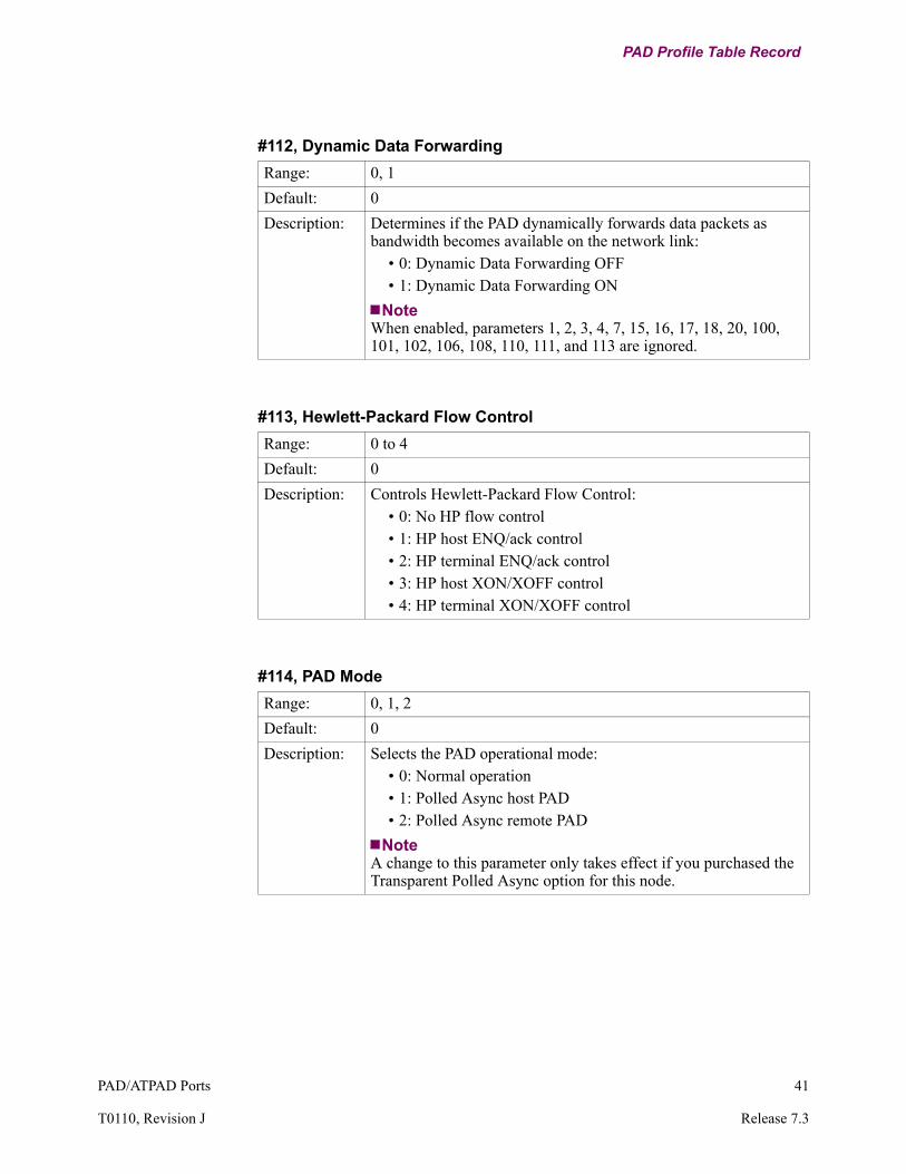
#112, Dynamic Data Forwarding
Range: 0, 1
Default: 0
Description: Determines if the PAD dynamically forwards data packets as bandwidth becomes available on the network link:
• 0: Dynamic Data Forwarding OFF• 1: Dynamic Data Forwarding ON
NoteWhen enabled, parameters 1, 2, 3, 4, 7, 15, 16, 17, 18, 20, 100, 101, 102, 106, 108, 110, 111, and 113 are ignored.
#113, Hewlett-Packard Flow Control
Range: 0 to 4
Default: 0
Description: Controls Hewlett-Packard Flow Control:• 0: No HP flow control• 1: HP host ENQ/ack control• 2: HP terminal ENQ/ack control• 3: HP host XON/XOFF control• 4: HP terminal XON/XOFF control
#114, PAD Mode
Range: 0, 1, 2
Default: 0
Description: Selects the PAD operational mode:• 0: Normal operation• 1: Polled Async host PAD• 2: Polled Async remote PAD
NoteA change to this parameter only takes effect if you purchased the Transparent Polled Async option for this node.

42 PAD/ATPAD Ports
PAD Profile Table Record
#115, Data Forwarding Criteria
Range: 0 to 2
Default: 0
Description: Specifies the Data Forwarding criteria:• 0: Normal• 1: Short timer• 2: Drop in RTS signal
NoteA change to this parameter only takes effect if you purchased the Transparent Polled Async option for this node.
#116, Short Timer Duration
Range: 0 to 255
Default: 0
Description: Specifies (in milliseconds) the Short Timer duration (when #115, Data Forwarding Criteria = 1). Zero (0) disables this parameter.
NoteA change to this parameter only takes effect if you purchased the Transparent Polled Async option for this node.
#117, EIA Signalling Action
Range: 0, 1
Default: 0
Description: Specifies the EIA signalling action (when #114, PAD Mode = 1 or 2).
• 0: None• 1: Raise DCD before and after transmission.
NoteA change to this parameter only takes effect if you purchased the Transparent Polled Async option for this node.
PAD/ATPAD Ports 43
T0110, Revision J Release 7.3
PAD Profile Table Record
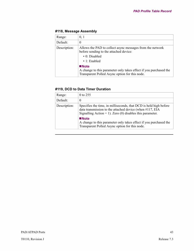
#118, Message Assembly
Range: 0, 1
Default: 0
Description: Allows the PAD to collect async messages from the network before sending to the attached device:
• 0: Disabled• 1: Enabled
NoteA change to this parameter only takes effect if you purchased the Transparent Polled Async option for this node.
#119, DCD to Data Timer Duration
Range: 0 to 255
Default: 0
Description: Specifies the time, in milliseconds, that DCD is held high before data transmission to the attached device (when #117, EIA Signalling Action = 1). Zero (0) disables this parameter.
NoteA change to this parameter only takes effect if you purchased the Transparent Polled Async option for this node.

44 PAD/ATPAD Ports
PAD Profile Table Record
Copying PAD Profile Tables into a Configuration
Introduction Each node processor card contains 14 PAD Profiles stored in memory.
By using the parameter values in the stored PAD Profile Table, you can copy them into the configuration memory as if you had entered the parameter values one parameter at a time.
The PAD accepts identifiers from 0 to 99. The profiles from 0 to 12, 90, and 91 are listed in this section. All the remaining profiles (0, 14-89, and 92-99) are DEFAULT as existing now.
PAD Profile Table Size
The Size of the PAD Profile Table has increased to 100 so that Entry Number 1 under PAD Profile Table configuration corresponds to Profile Identifier 0, Entry Number 2 to Profile Identifier 1, and so on. Entry Number 100 corresponds to Profile Identifier 99.
NoteYou cannot enter 0 as an Entry Number.
Copying a PAD Profile Table
Follow these steps to copy any of these PAD Profile Tables into your configuration:
Step Action Result
1 Select Copy/Insert Record -> Copy Special PAD Profile from PROM from the CTP Main menu.
This prompt appears:From Entry Number: 1/
Select the PAD Profile Table you want to copy into your configuration.
2 Type the entry number followed by <CR>.
You are then prompted for the next Entry Number (or just press <CR>). This allows you to configure more than one entry with the same stored PAD Profile Table.The parameter values in the stored PAD Profile Table are copied into the configuration memory (as if you had entered the parameter values one parameter at a time).
3 Press <ESC> once you are finished.
The Copy/Insert Record menu reappears.

PAD/ATPAD Ports 45
T0110, Revision J Release 7.3
PAD Profile Table Record
Parameter Values The parameter values for the 14 PAD Profiles are listed in these tables. For example, if you enter 0, you get all the values listed in the Default column.
Parameter Values Stored In Memory (0 to 5)
Parameter Name Default (0)
Test (1)
Simple (2)
Transpar (3)
CRT (4)
Printer (5)
#1 PAD Recall 1 1 1 0 1 1
#2 Echo 1 1 1 0 1 1
#3 Data Forwarding Character 2 2 126 0 2 2
#4 Idle Timer Delay 0 0 0 20 0 0
#5 Device Flow Control 0 1 1 0 0 2
#6 Service Signals Control 5 5 1 0 5 5
#7 Break Signal Operation 2 21 2 2 2 21
#8 Discard Output n/a n/a n/a n/a n/a n/a
#9 Padding After CR 0 0 0 0 0 5
#10 Line Folding 0 0 0 0 0 80
#11 Speed n/a n/a n/a n/a n/a n/a
#12 PAD Data Restraint 1 1 1 0 1 1
#13 LF Insertion After CR 4 4 0 0 4 4
#14 Padding After LF 0 0 0 0 0 5
#15 Editing 1 1 0 0 1 1
#16 Character Delete 8 8 8 8 8 8
#17 Line Delete 24 24 24 24 24 24
#18 Line Display 18 18 18 18 18 18
#19 Editing Type 2 1 1 1 2 1
#20 Echo Mask 255 0 0 0 255 255
#21 Parity Treatment 7 7 7 7 7 7
#22 Page Wait 0 0 0 0 0 0
#100 Break Character 0 0 0 0 0 0
#101 Echo Sub Toggle Character
0 0 0 0 0 0
#102 Echo Sub Character 0 0 0 0 0 0
#103 XON Character 17 17 17 17 17 17
#104 XOFF Character 19 19 19 19 19 19
#105 Data Restraint 0 0 0 0 0 0
#106 Network Parity 0 0 0 0 0 0
#107 Idle Disconnect Timer 0 0 0 0 0 0
#108 Disconnect Character 0 0 0 0 0 0
#109 Form Feed Padding 0 40 40 0 0 40
#110 ESC Forwarding Delay 0 0 0 0 0 0

46 PAD/ATPAD Ports
PAD Profile Table Record
#111 Echo Control 0 0 0 0 0 0
#112 Dynamic Data Forwarding
0 0 0 0 0 0
#113 Hewlett-Packard Flow Control
0 0 0 0 0 0
#114 PAD Mode 0 0 0 0 0 0
#115 Data Forwarding Criteria 0 0 0 0 0 0
#116 Short Timer Duration 0 0 0 0 0 0
#117 EIA Signalling Action 0 0 0 0 0 0
#118 Message Assembly 1 1 1 1 1 1
#119 DCD to Data Timer Duration
0 0 0 0 0 0
Parameter Values Stored In Memory (0 to 5) (continued)
Parameter Name Default (0)
Test (1)
Simple (2)
Transpar (3)
CRT (4)
Printer (5)
Parameter Values Stored in Memory (6 to 11)
Parameter Name DH_HPEA
(6)
DT_HPEA
(7)
DH_HPXON
(8)
DT_HPXON
(9)
TPA_HOST (10)
TPA_RMOT
(11)
#1 PAD Recall 0 0 0 0 0 0
#2 Echo 0 0 0 0 0 0
#3 Data Forwarding Character 0 2 2 2 0 0
#4 Idle Timer Delay 0 0 0 0 1 1
#5 Device Flow Control 0 2 0 0 0 0
#6 Service Signals Control 0 0 0 0 0 0
#7 Break Signal Operation 0 0 0 0 2 2
#8 Discard Output n/a n/a n/a n/a n/a n/a
#9 Padding After CR 0 0 0 0 0 0
#10 Line Folding 0 0 0 0 0 0
#11 Speed n/a n/a n/a n/a n/a n/a
#12 PAD Data Restraint 0 1 0 0 0 0
#13 LF Insertion After CR 0 0 0 0 0 0
#14 Padding After LF 0 0 0 0 0 0
#15 Editing 0 0 0 0 0 0
#16 Character Delete 8 8 8 8 8 8
#17 Line Delete 24 24 24 24 24 24
#18 Line Display 18 18 18 18 18 18
#19 Editing Type 2 2 2 2 1 1
#20 Echo Mask 255 255 255 255 0 0

PAD/ATPAD Ports 47
T0110, Revision J Release 7.3
PAD Profile Table Record
#21 Parity Treatment 7 7 7 7 7 7
#22 Page Wait 0 0 0 0 0 0
#100 Break Character 0 0 0 0 0 0
#101 Echo Sub Toggle Character
0 0 0 0 0 0
#102 Echo Sub Character 0 0 0 0 0 0
#103 XON Character 17 17 17 17 17 17
#104 XOFF Character 19 19 19 19 19 19
#105 Data Restraint 0 0 0 0 0 0
#106 Network Parity 0 0 0 0 0 0
#107 Idle Disconnect Timer 0 0 0 0 0 0
#108 Disconnect Character 0 0 0 0 0 0
#109 Form Feed Padding 0 0 0 0 0 0
#110 ESC Forwarding Delay 0 0 0 0 0 0
#111 Echo Control 0 0 0 0 0 0
#112 Dynamic Data Forwarding
0 0 0 0 0 0
#113 Hewlett-Packard Flow Control
1 2 3 4 0 0
#114 PAD Mode 0 0 0 0 1 2
#115 Data Forwarding Criteria 0 0 0 0 0 0
#116 Short Timer Duration 0 0 0 0 10 10
#117 EIA Signalling Action 0 0 0 0 1 0
#118 Message Assembly 1 1 1 1 1 1
#119 DCD to Data Timer Duration
0 0 0 0 0 0
Parameter Values Stored in Memory (6 to 11) (continued)
Parameter Name DH_HPEA
(6)
DT_HPEA
(7)
DH_HPXON
(8)
DT_HPXON
(9)
TPA_HOST (10)
TPA_RMOT
(11)

48 PAD/ATPAD Ports
PAD Profile Table Record
Values for Profiles 90 and 91
The parameter values for the International Simple (INT1984) and International Transparent (TRANSP1) profiles 91 and 92 are listed in this table.
PAD Bulletin Message
The PAD Bulletin Message is displayed when you connect to a PAD, and the Profile Parameter 6 (service signals control) is set to 5.
Parameter Values Stored in Memory
Parameter INT1984 (91) TRANSP1 (92)
1 Pad recall using a character 1 0
2 Echo 1 0
3 Data forwarding character 126 0
4 Idle timer delay 0 20
5 Ancillary device control 1 0
6 Control of PAD service signals
1 0
7 Break operating mode 2 2
8 Discard output 0 0
9 CR padding 0 0
10 Line folding 0 0
11 Baud rate 14 14
12 Flow control of the PAD 1 0
13 Linefeed insertion after CR 0 0
14 Padding after linefeed 0 0
15 Editing 0 0
16 Character delete 127 127
17 Line delete 24 24
18 Line display 18 18
19 Editing PAD service signal 1 1
20 Echo mask 0 0
21 Parity treatment 0 0
22 Page wait 0 0
NoteThe values for all remaining parameters are zero.

PAD/ATPAD Ports 49
T0110, Revision J Release 7.3
Remote PAD Parameter Table Record
Remote PAD Parameter Table Record
Introduction This record contains parameters that define a specified remote PAD. When a call is made to a port that uses this table entry, an X.29 set command is sent.
What You See In This Record
Figure 10 shows how the Remote PAD Parameter Table Record and its configuration parameters fit into the Vanguard products menu hierarchy.
Figure 10. Remote PAD Parameter Table Record
Before You Begin Before you can configure parameters, you must log on to the local node’s control terminal port. Refer to the Vanguard Configuration Basics Manual for CTP procedures.
Configuration Guidelines
When you configure the Remote PAD Parameter Table Record, do not use duplicate Parameter Numbers.
Accessing the Remote PAD Parameter Table Record
Follow these steps to access the Remote PAD Parameter Table record:
Entry NumberParameter NumberParameter Value
Node: Address: Date: Time:Menu: Configure Path: (Main.6)
NodePort
•••
Remote Parameter Table
Step Action Result
1 Select Configure from the CTP Main menu.
The Configure menu appears.
2 Select Remote PAD Parameter Table from the Configure menu.
The Remote PAD Parameter Table and its parameters appear.A prompt appears asking you to configure the next parameter.
3 Enter the parameter values.
4 Press <ESC> to return to the Configure menu after you have configured all parameters.

50 PAD/ATPAD Ports
Remote PAD Parameter Table Record
Remote PAD Parameter Table Record Parameters
Introduction This section describes the Remote PAD Parameter Record parameters.
Parameters You can configure these parameters (with the exception of Entry Number) from the Remote PAD Parameter Table Record:
Entry Number
Range: 1 to 6
Default: 1
Description: Identifies the PAD Parameter Table entry being configured by the other parameters in the record.
NoteNot configurable. Parameter Remote PAD Parameter Number in the PAD Port Record references this value.
#1 Parameter Number
Range: 0 to 127
Default: 0
Description: Specifies the X.3 parameter sent to a remote PAD that has just connected to a local PAD port. The selections correspond to the parameters in the PAD Profile Table:
• #1: PAD Recall character (0, 1,32 to 126)• #2: Echo (0, 1)• #3: Data Forwarding Character (0, 1 to 127)• #4: Idle Timer Delay (0, 1 to 255)• #5: Device Flow Control (0, 1, 2)• #6: Service Signals Control (0, 1, 4, 7 to 15)• #7: Break Signal Operation (0, 1, 4, 8, 16)• #8: Discard output (0, 1) (not supported by the 6500PLUS)• #9: Padding after Carriage Return (0 to 255)• #10: Line Folding (0, 1 to 255)• #11: Speed (0-18) (not supported by the 6500PLUS)• #12: PAD Data Restraint (0,1)• #13: Line Feed Insertion after CR (0, 1, 2, 4)• #14: Padding after LF (0 to 255)• #15: Editing (0, 1)• #16: Character Delete (0 to 127)• #17: Line Delete (0 to 127)

PAD/ATPAD Ports 51
T0110, Revision J Release 7.3
Remote PAD Parameter Table Record
Description:(Continued)
• #18: Line Display (0 to 127)• #19: Editing Type (0, 1, 2, 8, 32 to 126)• #20: Echo Mask (0 to 255)• #21: Parity Treatment (0 to 7) (normally not used)• #22: Page Wait (0, 1 to 255)• #100: Break Character (0 to 127)• #101: Echo Substitution Toggle Character (0 to 127)• #102: Echo Substitution Character (0 to 127)• #103: XON Character (0 to 255)• #104: XOFF Character (0 to 255)• #105: Control Signal (EIA-232-D) Data Restraint (0 to 3)• #106: Network Parity (0 to 4)• #107: Idle Disconnect Timer (0 to 255)• #108: Disconnect Character (0 to 127)• #109: Form Feed Padding (0 to 255)• #110: Esc Forwarding Delay Handling (0 to 255)• #111: Echo Control (0 to 3)• #112: Dynamic Data Forwarding (0, 1)• #113: Hewlett-Packard flow control (0 to 4)• #114: PAD Mode (0 to 2)• #115: Data Forwarding Criteria (0 to 2)• #116: Short Timer Duration (0 to 255)• #117: EIA Signalling Action (0, 1)• #118: Message Assembly (0, 1)• #119: DCD to Data Timer Duration (0 to 255)
If you enter 0 (zero), the entry is ignored.
#1 Parameter Number (continued)

52 PAD/ATPAD Ports
Remote PAD Parameter Table Record
#1 Parameter Value
Range: 0 to 255
Default: 0
Description: Specifies the X.3 parameter value (in the PAD Profile Table) sent to the remote PAD when connection is made.Entering an incorrect value for a particular parameter causes the value to be ignored.
Example:Step 1: Set the Parameter Value (or press <CR>). Result: The next Parameter Number appears, followed by the next Parameter Value. Step 2: Set a parameter value for #1 Parameter Number and #1 Parameter Value. Result: #2 Parameter Number and then #2 Parameter Value appear. The sequence repeats until you enter one of these occur:
• A Parameter Number and Parameter Value for each parameter listed in the PAD profile table
• <;> to implement the values <ESC> to abort the process

PAD/ATPAD Ports 53
T0110, Revision J Release 7.3
Detailed PAD Port Statistics
Detailed PAD Port Statistics
Function When you select Detailed PAD Port Statistics, a series of screens appears that provides information about the state and status of a PAD port.
What You See in the First Screen
Figure 11 shows the first screen of the Detailed PAD Port Statistics.
Figure 11. Example of Detailed PAD Port Statistics, First Screen
Description of Terms — First Screen
The first Detailed PAD Port Statistics screen contains this information:
Node: Address: Date: Time: Detailed PAD Statistics: Port 3 Page: 1 of 3
Port Number: 3 Port Type: ASYNC PAD Port Status: UpPort Speed: 9600 Port State: X28Port Utilization In: 0% Port Utilization Out: 0%
Physical: Parity Errors: 0 Overrun Errors: 0 Framing Errors: 0
Data Summary:IN OUT IN OUT
Characters: 0 0 Characters/sec: 0 0 Packets: 0 0 Packets/sec: 0 0 Number of Packets Queued: 0
EIA Summary: INPUT OUTPUTDTR RTS MB P14 DSR DCD RI CTS
State: Connected (SIMPLE) L L L L H H L H
Press any key to continue (ESC to exit)...
Screen Term Tells You...
Port Number Number of the port
Port Type Type of port: ASYNC PAD
Port Status Status of the port: Up
Port Speed The configured port speed
Port State These are the possible states:• X.28: The port is in Command mode• PAD: The port is in Data mode
Port Utilization: IN/OUT Percentage of port bandwidth being used

54 PAD/ATPAD Ports
Detailed PAD Port Statistics
What You See in the Second Screen
Figure 12 shows the second screen of the Detailed PAD Port Statistics.
Figure 12. Example of Detailed PAD Port Statistics, Second Screen
Physical Number of Parity, Overrun, and Framing errors since the last reset
Data Summary: IN/OUT Summary of the characters, packets, and frames being sent and received over the port
EIA Summary Summary of the EIA control signals being sent and received over the portPossible states are:
• NULL• Connected (SIMPLE)• Idle, Connected (DTR), Wait For Clear
(DTR), Wait for DTR (DTR)• Idle (DTRP), Call Detected (DTRP),
Connected (DTRP)• Idle, Call Detected (DIMO), Incoming
Call Detected (DIMO), Connected (DIMO), Clear Confirm (DIMO)
• Idle, RI On (EMRI), RI Off (EMRI), Wait for RTS (EMRI), Connected (EMRI), Wait for DTR (EMRI)
Screen Term Tells You... (continued)
Node: Address: Date: Time: Detailed PAD Statistics: Port 3 Page: 2 of 3
Call Summary: Current Status: Disconnected Time until next auto-call attempt: 0 secs
Number of auto-call attempts: 0 Last clear cause code: 0 (Cleared by other end) Last clear diagnostic code: 0 (No more information)
Last Inbound Call: Called Address: Calling Address: Facilities: CUD:
Last Outbound Call:Called Address:
Calling Address: Facilities: CUD:
Press any key to continue (ESC to exit)...

PAD/ATPAD Ports 55
T0110, Revision J Release 7.3
Detailed PAD Port Statistics
Description of Terms — Second Screen
The second Detailed PAD Port Statistics screen contains this information:
What You See in the Third Screen
Figure 13 shows the third screen of the Detailed PAD Port Statistics which lists the Current Running Profile information.
Figure 13. Example of Detailed PAD Port Statistics, Third Screen
Screen Term Tells You...
Call Summary • Current Status: Status of the call on the specific port (Disconnect, Calling, Called, Clearing, Connected, Local Copy)
• Time Until Next Autocall Attempt: Number of seconds until the next autocall is attempted
• Number of Autocall attempts: Number of autocalls that are attempted
• Last Clear Cause Code: Last clear cause code received by the port
• Last Clear Diagnostic Code: Last clear diagnostic code received by the port
Last Inbound Call Called Address, Calling Address, Facilities, and CUD of the last inbound call
Last Outbound Call Called Address, Calling Address, Facilities, and CUD of the last outbound call
Node: Address: Date: Time: Detailed PAD Statistics: Port 3 Page: 3 of 3
Current Running Profile: 1:1 2:1 3:2 4:0 5:0 6:5 7:2 8:0 9:0 10:0 11:14 12:1 13:4 14:0 15:1 16:8 17:24 18:18 19:2 20:255 21:7 22:0 100:0 101:0 102:0 103:17 104:19 105:0 106:0 107:0 108:0 109:0 110:0 111:0 112:0 113:0 114:0 115:0116:0 117:0 118:0 119:0
Press any key to continue (ESC to exit)...

56 PAD/ATPAD Ports
ATPAD Ports
ATPAD Ports
Introduction This section contains detailed descriptions of ATPAD ports, how they operate, and how to configure them.
ATPAD Operation
ATPAD An ATPAD port operates in either a Command mode or Data mode. This port type is always in the Command mode whenever a call is not taking place.
When the ATPAD is in the Command mode, it receives characters from the attached terminal device, processes them using the ATPAD command processor, and sends a response (or result code) to the terminal. It does not forward the command to the network.
The ATPAD is in Data mode when there is an X.25 network call in place to a remote device. In Data mode, it receives characters from the terminal device, packetizes them, and forwards them through the network to the remote device.
Result Code Printing Options
You can select one of these formats for printing with the Results Code port parameter:
• ALPHA—Result codes are printed in all capitals. They are printed on a new line and the cursor is advanced to the next new line. (<CR><LF> Result Code <CR><LF>).
• NUM—The numerical equivalent result code is printed followed by a <CR>.• NONE—No result codes are displayed.
Data Forwarding Criteria Descriptions
This table describes three criteria used to packetize and forward data to the network.
If you want to... Then use...
Forward data on full packets. Forward on full packet.The ATPAD always forwards full packets. You can configure the maximum packet size as 128, 256, 512, or 1024 bytes. You can select one of the other two criteria so that the ATPAD forwards data before a full packet has been assembled.
Packetize and forward the characters received since the last time expiration.
Forward on Data Forwarding Timer.You can use the Data Forwarding Timer in interactive sessions where the host (Echoplex) echoes the characters typed by the terminal equipment. If you want the characters to be echoed as quickly as possible, set the Data Forwarding Timer to a low value. If you set the Data Forwarding Timer to a zero value, you disable the ability to echo characters.
Send records or command to the host and terminated by the same character, for example, <CR>.
Forward on Data Forwarding Character.

PAD/ATPAD Ports 57
T0110, Revision J Release 7.3
ATPAD Ports
M-bit Handling M-bit handling allows the ATPAD to split data that is larger than the configured network packet size into packets for transmission on X.25. This is especially useful when the receiving end must identify the packets as part of one data stream.
The ATPAD port starts the data forwarding timer when it splits messages, data, or transactions from the terminal. If the next character arrives before the expiration of the forward timer, M-bit handling sets the first packet’s M-bit to 1 and passes the packet to the next layer. M-bit handling also sets the M-bit to 1 for the middle packets and sets the last packet’s M-bit to 0.
NoteEither Data Forwarding Character or Data Forwarding Timer must be enabled when M-bit handling is enabled. Both Data Forwarding Character and Data Forwarding Timer can be enabled simultaneously when M-bit handling is enabled.
DCD and DTR Control
You can configure your ATPAD connection for Data Carrier Detect (DCD). The DCD setting completes the connection process for DTR control. Choosing the DCD allows the ATPAD to connect like a modem.
The terminal screen displays OK only when the DTR pin is high. When the DTR pin’s input is high and a call is accepted, the DCD pin’s input goes to high. If the call is cleared or the DTR pin’s input is low, the DCD pin’s input goes to low. The DCD pin’s input remains low when no call is in place. If a call is in progress and the DTR pin’s input becomes low, the call is cleared. The No Carrier message appears on the terminal screen.
Flow Control You can configure the ATPAD for either type of flow control:
• Control Signal • XON/XOFF
If you select Control Signal, the port does not send data if the port's Pin 14 input is low. If the port wants to flow control the attached device, it sets its CTS output low.
If you configure the port for XON/XOFF, the port stops sending data if it receives the configured XOFF character. It resumes transmission when it receives an XON character. You can configure the XOFF and XON characters. If the port wants to flow control the attached device, it sends an XOFF character. Then it sends an XON character when it is ready to receive more data.
If the port's message queue overruns because flow control is not in effect, the port discards data and this alarm is generated:
Pn - DATA DISCARDED
where: P is the port identifier, and n is the port number.

58 PAD/ATPAD Ports
ATPAD Ports
Protocol Identifier You can use a Protocol Identifier (PID) to ensure that only calls from other devices using the same PID are accepted.
You configure a PID in the port record. The PID is inserted in the Call User Data field of all Call Request packets generated by the port. All incoming Call requests are checked for the presence of the same PID. If it is not present in the Call Request packet, the call is rejected.
If you leave the PID parameter blank, no PID is inserted in Call Requests, and there is no checking of incoming Call Request PIDs.
CUD and Facilities Call User Data (CUD) and facilities in incoming Call Request packets are ignored except for the PID. If you need to insert CUD and Facility fields in Call Request packets generated by the port, do this:
Network Parity Application
The application that the network parity feature has been designed for is as follows. An async device is directly connected to the ATPAD, and a call is made to an X.25 host. The ATPAD port currently strips parity on the incoming async data, so that the data on the X.25 link is always 8 bits, no parity. Normally, the PAD at the remote site regenerates parity when it transmits the data. In this application, the connection is to an X.25 host, which is expecting the data to be 7 bits, even parity.
This enhancement allows for selection of the parity requirements for data transmission. This configuration is shown in Figure 14.
Figure 14. ATPAD Application Environment
Step Action
1 Configure one of the Stored Addresses using the X.28 Call Command format.
2 Insert the appropriate CUD and Facilities fields in the configured Call Command string.
3 Use the ATDSn command referencing the correct Stored Address.
Async X.25
8 Bits, No ParityPC
NetworkAccess Product7 Bits
Even Parity
X.25Host

PAD/ATPAD Ports 59
T0110, Revision J Release 7.3
ATPAD Ports
Response Delay To slow down the responses sent by an ATPAD port, configure Response Time using this CSK:
BYSJWMYCCCKK6HE9NKEEThis CSK causes all ATPAD ports on the node to delay sending responses to commands for a period of one second.
This feature is designed for this situation. If an automated device that you are using to send commands to an ATPAD port has trouble recognizing the responses when they arrive too quickly, this feature delays responses. This feature is not recommended when the commands are being issued by a human operator.
NoteThe ATPAD does not have type-ahead capability, so commands that are sent before the response to the previous command has been received are ignored.
DTR Timeout The standard timeout period for DTR Connection Type is 1.5 seconds. That is, DTR must be OFF for 1.5 seconds before it is recognized as being OFF. You can configure a shorter timeout period with this CSK:
DTZEFG4JHTQY2HCFBJ66This CSK changes the timeout period for all ports on the node with DTR Connection Type to 100 ms. To guarantee reliable operation in this mode, a minimum OFF time of 150 ms for DTR is recommended.

60 PAD/ATPAD Ports
ATPAD Ports
ATPAD Port Record Parameters
Guidelines Use these guidelines when you enter ATPAD commands:
• Type the commands in upper, lower, or mixed case. If echo is enabled, the commands are echoed in all capitals.
• Use white space (TAB and SPACE) characters anywhere on the command line. The command processor ignores them.
• Edit the buffer using the configurable Back Space Character.• Be sure that you do not exceed the buffer's maximum length. Otherwise, you
get the result code ERROR.• Type AT<CR> to clear the command buffer.• Be aware that you can do the following:
- Enter commands that the ATPAD does not support. You get the result code OK, but the ATPAD does not act on the unsupported commands. The supported commands are: A/, AT, ATA, ATD, ATH, ATO, and form AT&Dn.
- Enter multiple commands on a single command line. However, the ATPAD recognizes only the first supported command.
Configuring The ATPAD
To configure the ATPAD, use the CTP to access the Configure menu and select Port (See Figure 15). You can perform these standard Port Control functions using the CTP:
• Port Boot• Port Enable• Port Disable• Port Busy-out
Figure 15. Configure ATPAD Port Menu
Escape Sequence TimerData Forwarding TimerPacket SizeCommand Echo: ON/Answer ModeStored Address 0Stored Address 1Stored Address 2Stored Address 3Result CodesRestricted Connection DestinationPort AddressBilling RecordsProtocol IDNetwork ParityPort Options
Port NumberPort TypeConnection TypeClock SpeedData Bits per CharacterDevice ParityNumber of Stop BitsEscape CharacterCarriage Return CharacterLine Feed CharacterBack Space CharacterData Forwarding CharacterXOFF CharacterXON CharacterFlow Control
Node: Address: Date: Time: Menu: Configure Path:
NodePort

PAD/ATPAD Ports 61
T0110, Revision J Release 7.3
ATPAD Ports
Parameters These are the port parameters when Port Type is set to ATPAD. Any parameter with an asterisk (*) requires a Node boot.
NoteIf you have enabled Ease of Configuration, you need to boot only the port to make changes to the parameters marked with an asterisk. For more information, refer to the Ease of Configuration section in the introductory portion of the Basic Protocols Manual, (Part Number T0106).
*Port Type
Range: NULL, PAD, ATPAD, X25
Default: PAD
Description: Specifies the port type.• NULL: NULL port• PAD: PAD port• ATPAD: ATPAD port• X25: X.25 port
Connection Type
Range: SIMP, DTR, DCD
Default: SIMP
Description: Specifies the control signal handshaking required for a connection to be made to this port.
• SIMP: Simple, no control signals required• DTR: Dedicated, requires the data terminal ready signal
(DTR)• DCD: High when the call is connected; otherwise, it is Low.
Clock Speed
Range: 50, 75, 100, 110, 134, 150, 200, 300, 600, 1200, 1800, 2400, 4800, 7200, 9600, 19200, 38400, 57600, 115200, 75/1200
Default: 9600
Description: Specifies the port speed in bits per second, when using internal clocking. The maximum port speed depends on the Vanguard platform.

62 PAD/ATPAD Ports
ATPAD Ports
Data Bits
Range: 7, 8
Default: 8
Description: Number of bits per character when transmitting and receiving data.
NotePerform a Port boot to implement changes to this parameter.
Parity
Range: NONE, SPAC, MARK, EVEN, ODD
Default: NONE
Description: The parity the port uses when transmitting and receiving data• NONE: No parity• SPAC: Space Parity• MARK: Mark Parity• EVEN: Even Parity• ODD: Odd Parity
NotePerform a Port boot to implement changes to this parameter.
Stop Bits
Range: 1, 1.5, 2
Default: 1
Description: The number of stop bits generated by the port when transmitting. This parameter has no effect on data received by the port.
• 1: 1 Stop Bit• 1.5: 1.5 Stop Bits• 2: 2 Stop Bits
NotePerform a Port boot to implement changes to this parameter.

PAD/ATPAD Ports 63
T0110, Revision J Release 7.3
ATPAD Ports
Escape Character
Range: 0 to 255
Default: 43
Description: Specifies the character used to escape the Command Mode.
NotePerform a Port boot to implement changes to this parameter.
Carriage Return Character
Range: 0 to 255
Default: 13
Description: Specifies the character used to insert a carriage return.
NotePerform a Port boot to implement changes to this parameter.
Line Feed Character
Range: 0 to 255
Default: 10
Description: Specifies the character used to move the cursor to a new line.
NotePerform a Port boot to implement changes to this parameter.
Back Space Character
Range: 0 to 255
Default: 8
Description: Specifies the character used for character editing.
NotePerform a Port boot to implement changes to this parameter.

64 PAD/ATPAD Ports
ATPAD Ports
Data Forwarding Character
Range: 0 to 255
Default: 13
Description: Packets are forwarded to the network when this character is received. To disable this function, set to zero (0).
NotePerform a Port boot to implement changes to this parameter.
XOFF Character
Range: 0 to 255
Default: 19
Description: Specifies the value of the ASCII character used for the XOFF function.
NotePerform a Port boot to implement changes to this parameter.
XON Character
Range: 0 to 255
Default: 17
Description: Specifies the value of the ASCII character used for the XON function.
NotePerform a Port boot to implement changes to this parameter.
Flow Control
Range: NONE, CNTL, XOFF
Default: NONE
Description: Specifies the type of flow control that the port uses:• NONE: No flow control• CNTL: Control signal flow control• XOFF: XON/XOFF flow control
NotePerform a Port boot to implement changes to this parameter.

PAD/ATPAD Ports 65
T0110, Revision J Release 7.3
ATPAD Ports
Escape Sequence Timer
Range: 1 to 51
Default: 10
Description: Value of the escape time (in 1/10 second increments).
NotePerform a Port boot to implement changes to this parameter.
Data Forwarding Timer
Range: 0 to 255
Default: 0
Description: Specifies how long the system waits (in 1/20 second increments) before data is packetized and sent to the network. To disable this timer, set to zero (0).
NotePerform a Port boot to implement changes to this parameter.
Packet Size
Range: 128, 256, 512, 1024
Default: 128
Description: Specifies the maximum size of packets that the ATPAD forms.
NotePerform a Port boot to implement changes to this parameter.
Echo
Range: ON, OFF
Default: ON
Description: Specifies whether Echo is enabled (ON) or disabled (OFF) when the port is in the Command Mode.
NotePerform a Port boot to implement changes to this parameter.

66 PAD/ATPAD Ports
ATPAD Ports
Answer Mode
Range: AUTO, MAN, NONE
Default: AUTO
Description: Determines whether incoming calls are answered (using ATA commands) automatically (AUTO) or manually (MAN). NONE bars incoming calls.
NotePerform a Port boot to implement changes to this parameter.
Stored Addresses
Range: 4 sets of 0 to 64 alphanumeric characters
Default: (blank)
Description: Used to make calls with the ATDSn command. The addresses may be in mnemonic form (if preceded by a DOT) or in the form of an X.28 call command.The space bar blanks this field.
NotePerform a Port boot to implement changes to this parameter.
Result Codes
Range: ALPHA, NUM, NONE
Default: ALPHA
Description: Specifies how result codes are displayed:• ALPHA: spells out the result code• NUM: displays a numeric equivalent for the result code• NONE: suppresses result code generation.
NotePerform a Port boot to implement changes to this parameter.
Restricted Connection Destination:
Range: 0 to 32 characters
Default: (blank)
Description: All calls entering this port are routed to the destination specified in this parameter regardless of route selection table entries. The space bar blanks the field.
NotePerform a Port boot to implement changes to this parameter.
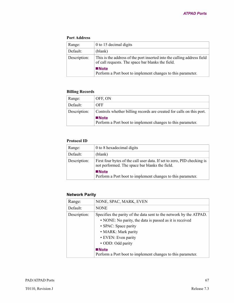
PAD/ATPAD Ports 67
T0110, Revision J Release 7.3
ATPAD Ports
Port Address
Range: 0 to 15 decimal digits
Default: (blank)
Description: This is the address of the port inserted into the calling address field of call requests. The space bar blanks the field.
NotePerform a Port boot to implement changes to this parameter.
Billing Records
Range: OFF, ON
Default: OFF
Description: Controls whether billing records are created for calls on this port.
NotePerform a Port boot to implement changes to this parameter.
Protocol ID
Range: 0 to 8 hexadecimal digits
Default: (blank)
Description: First four bytes of the call user data. If set to zero, PID checking is not performed. The space bar blanks the field.
NotePerform a Port boot to implement changes to this parameter.
Network Parity
Range: NONE, SPAC, MARK, EVEN
Default: NONE
Description: Specifies the parity of the data sent to the network by the ATPAD.• NONE: No parity, the data is passed as it is received• SPAC: Space parity• MARK: Mark parity• EVEN: Even parity• ODD: Odd parity
NotePerform a Port boot to implement changes to this parameter.

68 PAD/ATPAD Ports
ATPAD Ports
Port Options
Range: NONE, MBIT
Default: NONE
Description: Enables the M-bit option:• NONE: No port option is selected. • MBIT: Sets M-bit for X.25 packets of the configured network
packet size.
NoteEither Data Forwarding Character or Data Forwarding Timer must be enabled when M-bit handling is enabled. Both Data Forwarding Character and Data Forwarding Timer can be enabled simultaneously.

PAD/ATPAD Ports 69
T0110, Revision J Release 7.3
ATPAD Ports
ATPAD Port Statistics
Function When you select Detailed ATPAD Port Statistics, a series of screens appears that provides information about the state and status of the ATPAD port.
What You See in the First Screen
Figure 16 illustrates the first screen of Detailed ATPAD Port Statistics.
Figure 16. ATPAD Port Statistics - Screen 1
Description of Terms — First Screen
The first Detailed ATPAD Port Statistics screen contains this information:
Node: Address: Date: Time: Detailed ATPAD Port Statistics: Port 3 Page: 1 of 2
Port Number: 3 Port Type: ATPAD Port Status: UpPort Speed: 9600 Port State: DataPort Utilization In: 0% Port Utilization Out: 1%
Physical Summary: Parity Errors: 0 Overrun Errors: 0 Framing Errors: 0
Data Summary:IN OUT IN OUT
Characters: 252 3807 Characters/sec: 0 18Packets: 252 274 Packets/sec: 0 0
Number of Packets Queued: 0
Interface Summary: EIA-232-D DCE INPUT OUTPUTDTR RTS MB P14 DSR DCD RI CTS
State: Connected (SIMPLE) H H H L L H H L
Press any key to continue (ESC to exit)...
Screen Term Description
Port Number Number of the port
Port Type Type of port: ATPAD
Port Status Status of the port: Up
Port Speed The configured port speed
Port State These are the possible states:• ATPAD: The port is in Command mode• PAD: The port is in Data mode
Port Utilization: IN/OUT Percentage of port bandwidth being used
Physical Summary Number of Parity, Overrun, and Framing errors since the last reset
Data Summary: IN/OUT Summary of the characters, packets, and frames being sent and received over the port

70 PAD/ATPAD Ports
ATPAD Ports
What You See in the Second Screen
Figure 17 illustrates the second screen of Detailed ATPAD Port Statistics.
Figure 17. ATPAD Port Statistics - Screen 2
Interface Summary Summary of the EIA control signals being sent and received over the portThese are the possible states:
• NULL• Connected (SIMPLE)• Idle, Connected (DTR), Wait For Clear
(DTR), Wait for DTR (DTR)• Idle (DTRP), Call Detected (DTRP),
Connected (DTRP)• Idle, Call Detected (DIMO), Incoming
Call Detected (DIMO), Connected (DIMO), Clear Confirm (DIMO)
• Idle, RI On (EMRI), RI Off (EMRI), Wait for RTS (EMRI), Connected (EMRI), Wait for DTR (EMRI)
Screen Term Description (continued)
Node: Address: Date: Time: Detailed ATPAD Port Statistics: Port 3 Page: 2 of 2
Call Summary: Current Status: Data Transfer Last clear cause code: 0 (Cleared by other end) Last clear diagnostic code: 0 (No more information)
Last Inbound Call: Called Address: 20098 Calling Address: 20003 Facilities: CUD:
Last Outbound Call: Called Address: Calling Address: Facilities: CUD:
Press any key to continue (ESC to exit)...

PAD/ATPAD Ports 71
T0110, Revision J Release 7.3
ATPAD Ports
Description of Terms — Second Screen
The second Detailed PAD Port Statistics screen contains this information:
Screen Term Description
Call Summary • Current Status: Status of the call on the specific port (Data Transfer, Calling, Called, Clearing, Connected, Local Copy)
• Last Clear Cause Code: Last clear cause code received by the port
• Last Clear Diagnostic Code: Last clear diagnostic code received by the port
Last Inbound Call Called Address, Calling Address, Facilities, and CUD of the last inbound call
Last Outbound Call Called Address, Calling Address, Facilities, and CUD of the last outbound call


Index
Index-1
Symbols
#1, PAD Recall 30#10, Line Folding 33#100, Break Character 37#101, Echo Substitution Toggle Character 37#102, Echo Substitution Character 37#103, XON Character 38#104, XOFF Character 38#105, Control Signal (EIA-232-D) Data
Restraint 38#106, Network Parity 39#107, Idle Disconnect Timer 39#108, Disconnect Character 39#109, Form Feed Padding 39#110, Esc Forwarding Delay Handling 40#111, Echo Control 40#112, Dynamic Data Forwarding 41#113, Hewlett-Packard Flow Control 41#114, PAD Mode 41#115, Data Forwarding Criteria 42#116, Short Timer Duration 42#117, EIA Signalling Action 42#118, Message Assembly 43#119, DCD to Data Timer Duration 43#12, PAD Data Restraint 33#13, Line Feed Insertion After CR 34#15, Editing 34#16, Character Delete 35#17, Line Delete 35#18, Line Display 35#19, Editing Type 35#2, Echo 30#20, Echo Mask 36#21, Parity Treatment 36#22, Page Wait 37#3, Data Forwarding Character 31#4, Idle Timer Delay 31#5, Device Flow Control 32#6, Service Signals Control 32#7, Break Signal Operation 32#9, Padding After Carriage Return 33
A
APADenabling the CSK 25XON/XOFF transmission
using X.25 interrupt packets 25
A (Continued)
ATPADDTR timeout 59response delay 59
Auto Baud Sequence 11Autobaud sequence 24Autocall Mnemonic
inputting a value 7specifying 7
Autocall Timeoutguidelines 7
Autocall Timeout (sec) 15Autocalling
attempts 16SDLC 23
Autospeed 11, 24implementing 24
B
Billing Printer Mnemonicspecifying 7
Billing Recordsguidelines 7
Break Character 37Break Signal Operation 32
C
Call Accept Timeout 17Call Control 13
setting 7Call User Data (CUD) 58Calling
initiating 22SDLC 23
Character Delete 35Clear packet 17Configuration
PAD prompt table 26Remote PAD Parameter Table 49
Connection TypeDTRP 8PAD Port 8SIMP 7
Control Terminal Port 1CUG 16
membership 16setting for Terminal Control 7

Index-2
D
Data Bits per Character 12Data Connection Protection 18Data Forwarding Character 31Data Forwarding Criteria 42Data Restraint 38DCD Control 57DCD to Data Timer Duration 43DCP 18Device Flow Control 32Disconnect Character 39DTR timeout 59Dynamic Data Forwarding 41
E
Echo 30Echo Control 40Echo Mask 36Echo Substitution Character 37Echo Substitution Toggle Character 37Editing 34Editing Type 35EIA Signalling Action 42Esc Forwarding Delay Handling 40
F
Flow Control 57Flow control 32, 33Form Feed Padding 39
G
Group Subaddress 16
H
Hewlett-Packard Flow Control 41
I
Idle Disconnect Timer 39Idle Timer Delay 31Invitation to clear 17
L
Line Delete 35Line Display 35Line Feed Insertion After CR 34Line Folding 33
M
Maximum Number of Autocall Attempts 16guidelines 7
MBC Protocol 4configuring 5
M-bit handling 57Message Assembly 43Mnemonic
autocalling 22Table
specifying Autocall Mnemonic 7
N
NUI Tableguidelines 7
Number of Stop Bits 12
P
PAD 53PAD Data Restraint 33PAD Mode 41PAD port
additional records 7subaddress 16
PAD profile parameter 52PAD Profile Table 7PAD profiles 44, 52PAD Prompt Entry Number 15
specifying 7PAD Prompt table
configure 26guidelines 7
PAD Prompt Text 27PAD Recall 30Padding After Carriage Return 33Page Wait 37Parameter Value 52Parity 39Parity Treatment 36PID 58Port Speed 10Port Statistics
port state 53, 69Profile Name
specifying 7Protection Level 18Protocol Identifier 58

Index-3
R
Reconnection Timeout 18Reconnection Tries Limit 18Remote PAD Parameter Table
configure 49Remote PAD Parameters
Number 7, 15Table 7
Response delay 59
S
SDLCautocalling mnemonic 23
Service Signals Control 32Short Timer Duration 42Speed
port 10Stop bits 12Subaddress 16
group 16
T
Terminal Control 14guidelines 7
Timer 31
X
XOFF Character 38XON Character 38XON/XOFF
transmittingusing X.25 interrupt packets 25


Index-5

Index-6


