
Valmet Conductivity Measurement
Series 3100
Installation &operating manual
K15344 V1.1 EN

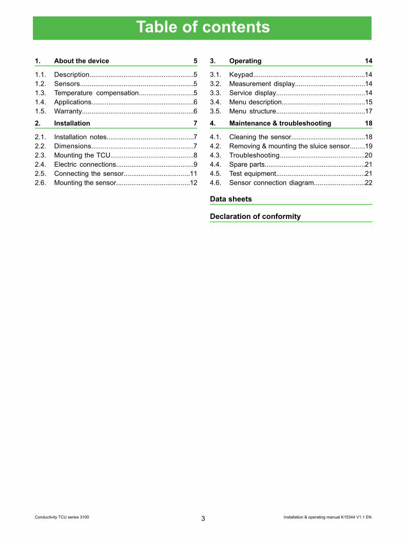
Table of contents
About the device 51.
Description.......................................................51.1.Sensors............................................................51.2.Temperature compensation.............................51.3.Applications......................................................61.4.Warranty...........................................................61.5.
Installation 72.
Installation notes..............................................72.1.Dimensions......................................................72.2.Mounting the TCU............................................82.3.Electric connections.........................................92.4.Connecting the sensor...................................112.5.Mounting the sensor.......................................122.6.
Operating 143.
Keypad...........................................................143.1.Measurement display.....................................143.2.Service display...............................................143.3.Menu description............................................153.4.Menu structure...............................................173.5.
Maintenance & troubleshooting 184.
Cleaning the sensor.......................................184.1.Removing & mounting the sluice sensor........194.2.Troubleshooting.............................................204.3.Spare parts.....................................................214.4.Test equipment...............................................214.5.Sensor connection diagram...........................224.6.
Data sheets
Declaration of conformity
Installation & operating manual K15344 V1.1 EN3Conductivity TCU series 3100
Recycling and disposal
When sorted by material, nearly all parts of the device can be recycled.A materials list is delivered with the device. Upon request, the manufac-turer will provide more detailed instructions for recycling and disposal.
Used devices may also be returned to the manufacturer for recycling anddisposal against a separate fee.
The equipment contains no batteries.
4
1. About the device1.1. DescriptionThe series 3100 Conductivity TCU is designed for highand low conductivity measurement in combination withValmet 4-electrode conductivity sensors series 4000and 4200. It is designed for wall mounting or panelmounting in industrial plant environments.
The TCU has four individually selectable set-upmodes, two for UPW/WFI (low conductivity) and twofor high conductivities. Each of the four set-up modeshas access to individual setting of temperature com-pensation, output range, alarm, and calibration. Theset-up modes are selectable remotely or from thekeypad.
The TCU has two 4–20 mA current outputs, a dis-play, and a keypad. The line-powered version has tworelays for alarms. Optionally the HART® protocol forfield device transmitters can be implemented. For thefull specifications, please refer to 915.19 HART FieldDevice Specification for series 3000.
TCU versions, type no. (for HART® communication:add "H" to type number.
Line poweredLooppowered
31173107Wall mounted
31183108Panel mounted
1.2. SensorsAll sensors are based on the 4-electrode principle ac-cording to which the current and the voltage aremeasured across separate electrodes. That eliminatesthe errors from the polarization effect that is generallya problem at high conductivities.
The value of the cell constant is stored in the sensor.This makes all sensors interchangeable without sacrifi-cing accuracy and without the need for recalibration orre-entering the cell-constant when exchanging thesensor. A large selection of sensor types is availablemeeting the needs for almost any application.
1.3. Temperature compensationIn an electrolyte, all ions present will contribute to theconductivity. Different ions will contribute with differentamounts and the amounts will vary with temperature.When the conductivity is used for the calculation of achemical concentration, it is necessary to calculatewhat the conductivity would be at a fixed temperature(the conductivity is temperature compensated). Thisconductivity is calculated from measured conductivityand temperature. As different ions have different tem-perature dependences, the temperature compensationis to be selected to fit the actual application. The tem-perature is measured with a Pt-1000 resistor in thesensor.
Ultrapure water (UPW) contains a very small amountof impurities, and the resulting conductivity arises fromthe impurity ions as well as from the autoprotolysis ofthe water. Strong or weak acids or bases (present asimpurity ions in very small amounts) affect the autopro-tolysis differently, and thus contribute differently to theconductivity. The conductivity from the impurity andfrom the autoprotolysis changes differently with temper-ature, and the temperature compensation algorithmshave to compensate accordingly. The UPW-conductivityset-up includes temperature compensation algorithmsfor ultrapure water with the impurities found in commonuse.
Installation & operating manual K15344 V1.1 EN5Conductivity TCU series 3100

1.4. ApplicationsThe series 3100 Conductivity TCU is designed for ul-trapure water applications in power plants and inpharmaceutical industries, for cleaning in place (CIP)applications in breweries and diaries and for generaluse as a conductivity meter.
UPW conductivity set up, temperature compensations.Reference temperature 25°C.
OFF
0–130°CUPW-Neutral
0–100°CUPW-Acidic
0–100°CUPW-Alkaline
0–100°CUPW-Ammonia
0–200°CSTD Salt
0–150°CIEC 746-BII
UPW conductivity set up, temperature compensations.Reference temperature 25°C.
OFF
0–130°CUPW-Neutral
0–100°CUPW-Acidic
0–100°CUPW-Alkaline
0–100°CUPW-Ammonia
0–200°CSTD Salt
0–150°CIEC 746-BII
Installation & operating manual K15344 V1.1 EN6Conductivity TCU series 3100

2. Installation2.1. Installation notesWhen planning the installation of the series 3000 con-ductivity TCU, a number or issues have to be con-sidered:• Whether mounted on a wall, in a panel or onto a
piping or cable tray, the place should be free of vi-brations and mechanically shocks should not occur.
• Protect the instrument from process electrolyte, andfrom downpour. If necessary use a Protection Shield.
• Protect the instrument from excessively high or lowtemperatures and from direct sunlight.
• Be aware of the sensors requirements for liquorvolume around the sensor tip.
• Mount the sensor at a place where it is protectedfrom mechanical impact, where it can be accessedand extracted from the process liquor for servicejobs, and where the process liquor is properlygrounded via the process piping.
• Minimize the length of sensor cable as much aspossible.
• Protect the sensor cable from mechanical impact,excessive high or low temperatures and processelectrolyte.
• Look up for ground loop currents, which can causea fluctuating or faulty reading. There should be nopotential between the mounting place of the TCUcase and the sensor. If mounting the TCU on a cabletray, the cable tree should be electrically connectedto the process piping. Also, look up for a potentialdifference between the protective ground and theprocess piping and/or the mounting place of theTCU.
• A special situation arises where the process pipingis made by isolating material e.g. PTFE lined steelpiping, PVC or PP piping, giving no ground connec-tion of the process electrolyte. If the sensor is of thetype where no metal structure is in electrical contactwith the process electrolyte giving a grounding ofthe process electrolyte that way, it is necessary toestablish a grounding electrode in the processelectrolyte, which must be connected to the metalstructure of the sensor or to the housing of the TCU.
2.2. Dimensions
OKesc
144Ø5.2
11614
4
153
107
26.55
Fig. 1. Installation dimensions, in millimeters.
Installation & operating manual K15344 V1.1 EN7Conductivity TCU series 3100
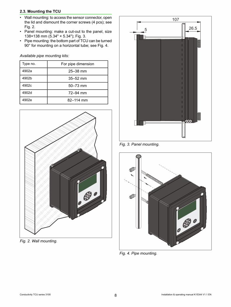
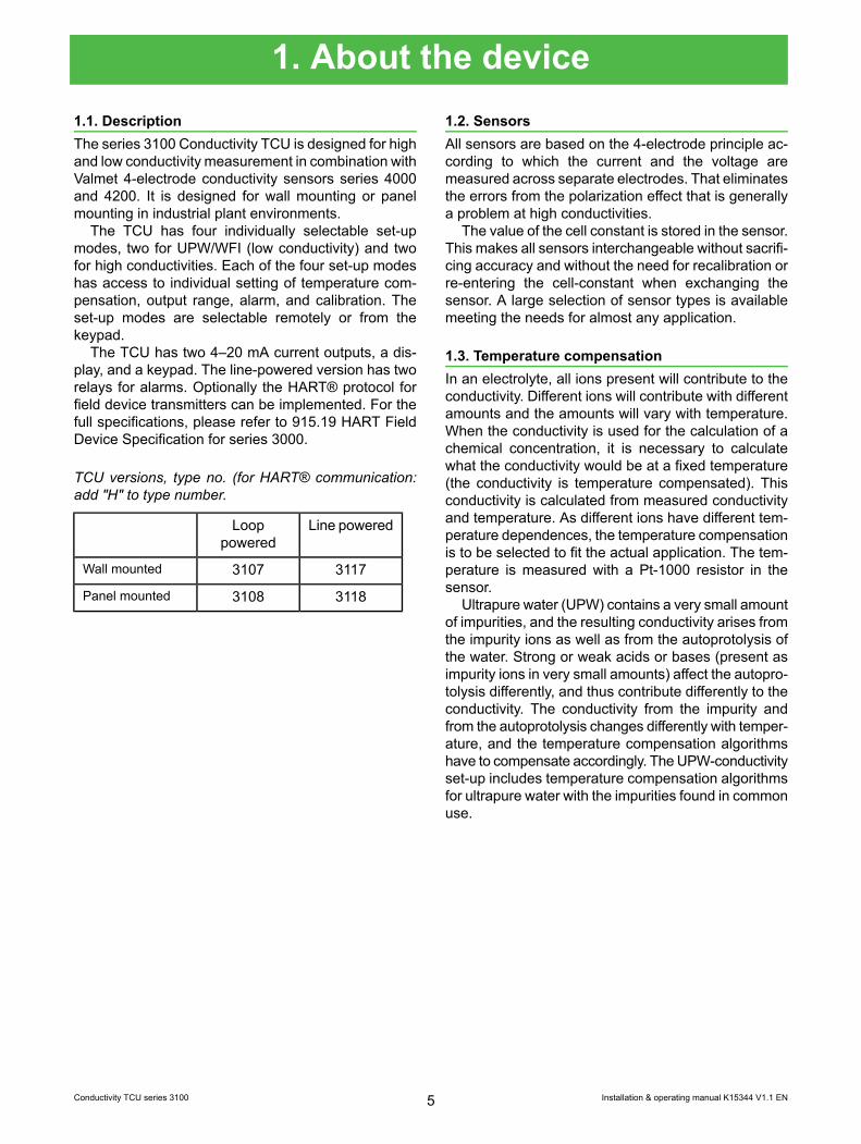
2.3. Mounting the TCU• Wall mounting: to access the sensor connector, open
the lid and dismount the corner screws (4 pcs); seeFig. 2.
• Panel mounting: make a cut-out to the panel, size138×138 mm (5.34" × 5.34"); Fig. 3.
• Pipe mounting: the bottom part of TCU can be turned90° for mounting on a horizontal tube; see Fig. 4.
Available pipe mounting kits:
For pipe dimensionType no.
25–38 mm4902a
35–52 mm4902b
50–73 mm4902c
72–94 mm4902d
82–114 mm4902e
Fig. 2. Wall mounting.
107
26.55
Fig. 3. Panel mounting.
Fig. 4. Pipe mounting.
Installation & operating manual K15344 V1.1 EN8Conductivity TCU series 3100

2.4. Electric connections
mA1 mA2
+ - + + - +-A Com B
+-
Power supplyNo. 1
16 - 30 V DC
+-
Power supplyNo. 3
12 - 30 V DC
+-
Power supplyNo. 2
6 - 30 V DCOptional
Optional
SASB
Input load 4.4K
SAOffOnOffOn
SBOffOffOnOn
Set-up 1Set-up 2Set-up 3Set-up 4
J3
J2
1 2 3 4 5 6 7
Outputs ControlmA1 mA2+ - + +A 0 +B
-
J111
109
87
65
43
Sen
sor
21
Fig. 5. Loop powered version. Switches SA and SB control the selection of set-up as indicated.
Installation & operating manual K15344 V1.1 EN9Conductivity TCU series 3100
SAOffOnOffOn
SBOffOffOnOn
Set-up 1Set-up 2Set-up 3Set-up 4
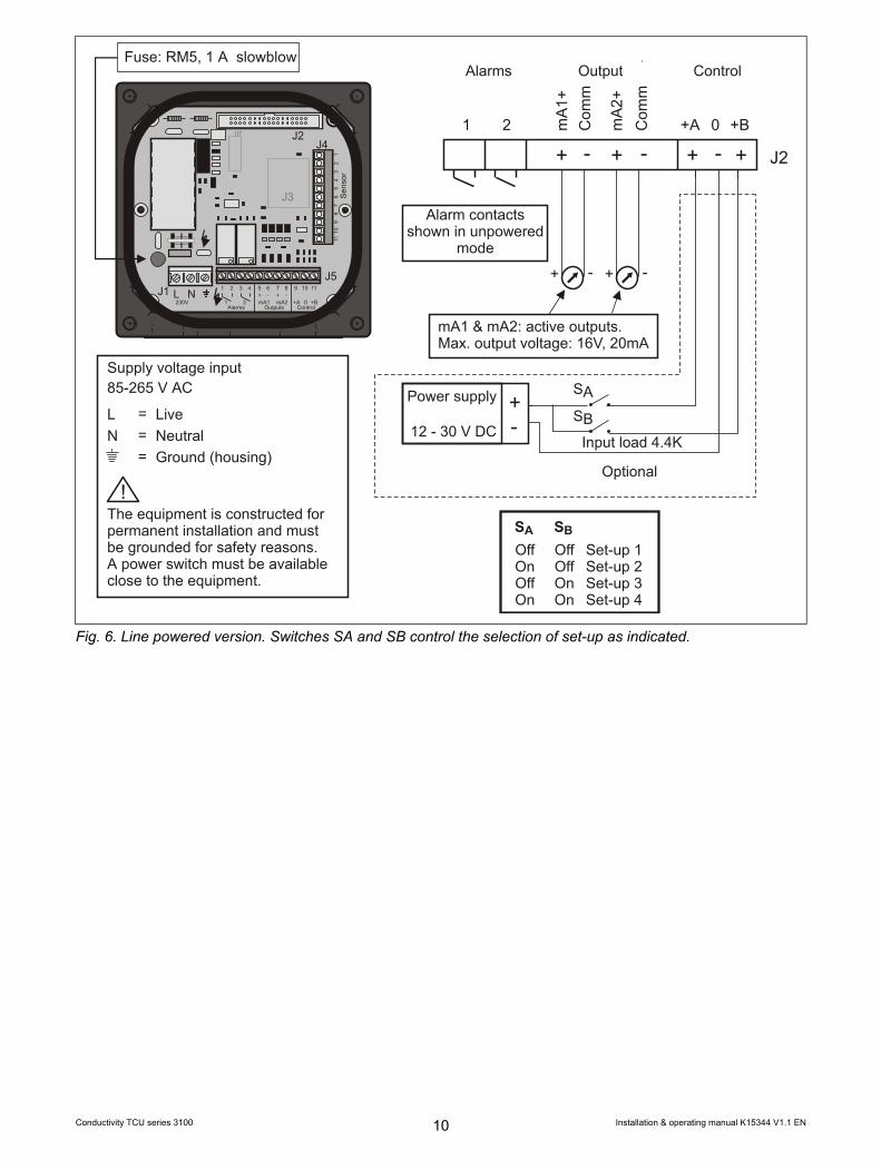
Supply voltage input85-265 V AC
LN
===
LiveNeutralGround (housing)
The equipment is constructed forpermanent installation and mustbe grounded for safety reasons.A power switch must be availableclose to the equipment.
Fuse: RM5, 1 A slowblow
L N
J2
J3
U7
J4
J1J5
1 2 3 4 5+ +- -
6 7 8 9 10 11
Alarms230V
Outputs Control1 2 mA1 mA2 +A +B0
1110
98
76
54
3S
enso
r2
1 J2
mA
2+C
omm
Com
mm
A1+
1 2 +A 0 +B
Alarm contactsshown in
modeunpowered
+ ++ - - -+
mA1 & mA2: active outputs.Max. output voltage: 16V, 20mA
Alarms Output Control
+-
Power supply
12 - 30 V DC
Optional
SASB
Input load 4.4K
Fig. 6. Line powered version. Switches SA and SB control the selection of set-up as indicated.
Installation & operating manual K15344 V1.1 EN10Conductivity TCU series 3100
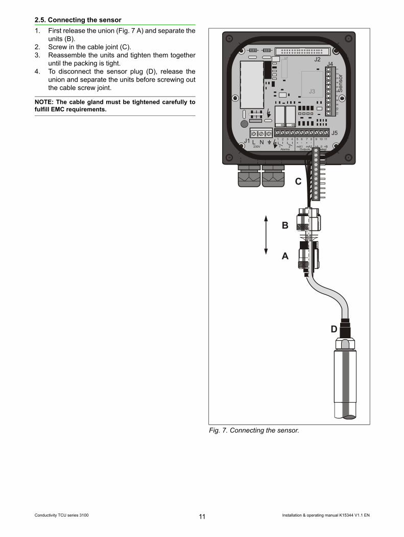
2.5. Connecting the sensor1. First release the union (Fig. 7 A) and separate the
units (B).2. Screw in the cable joint (C).3. Reassemble the units and tighten them together
until the packing is tight.4. To disconnect the sensor plug (D), release the
union and separate the units before screwing outthe cable screw joint.
NOTE: The cable gland must be tightened carefully tofulfill EMC requirements.
L N
J2
J3
U7
J4
J1J5
1 2 3 4 5+ +- -
6 7 8 9 10 11
Alarms230V
Outputs Control1 2 mA1 mA2 +A +B0
1110
98
76
54
3S
enso
r21
A
B
C
D
Fig. 7. Connecting the sensor.
Installation & operating manual K15344 V1.1 EN11Conductivity TCU series 3100

2.6. Mounting the sensorThe sensor should be mounted at a place where therewill be no occurrence of air pockets or bubbles. Thebest installation is obtained across a pump (a) or in anupstream pipe (b), (e); Fig. .
If the sensor is mounted in a downstream pipe themounting point shall be moved away from locationswhere an air funnel may be created (c), (d), otherwiseit may be necessary to insert a flow damper just afterthe measuring point (f), (g).
If a continuous TCU is wanted even in case the piperuns empty, an installation like (h) can be used. Thesensor is mounted at the under side of the horizontalpipe in a cone, to let air bubbles pass without disturbingthe TCU.
Sensor (i) is used to for concentration control in aloop. The dosing is injected before the sensor, prefer-ably with a pump between the dosage and the sensorto provide for mixing before the TCU. The sensor ismounted on the pressure side of pump to minimize in-fluence from air bubbles.
It is recommended to install valves so that the sensorcan be removed for service without a shutdown of theprocess.
d
a
cb
gf
e
Return
i
h
Fig. 8. Preferred sensor mounting locations.
Installation & operating manual K15344 V1.1 EN12Conductivity TCU series 3100
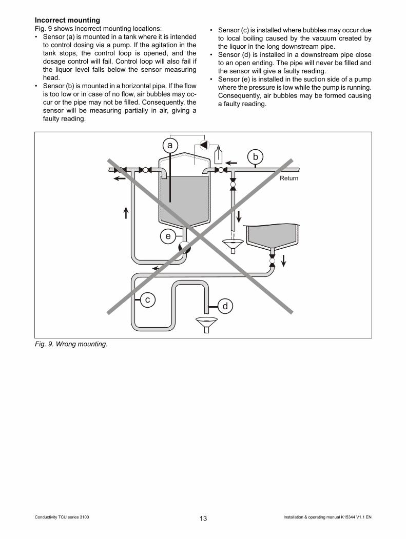
Incorrect mountingFig. 9 shows incorrect mounting locations:• Sensor (a) is mounted in a tank where it is intended
to control dosing via a pump. If the agitation in thetank stops, the control loop is opened, and thedosage control will fail. Control loop will also fail ifthe liquor level falls below the sensor measuringhead.
• Sensor (b) is mounted in a horizontal pipe. If the flowis too low or in case of no flow, air bubbles may oc-cur or the pipe may not be filled. Consequently, thesensor will be measuring partially in air, giving afaulty reading.
• Sensor (c) is installed where bubbles may occur dueto local boiling caused by the vacuum created bythe liquor in the long downstream pipe.
• Sensor (d) is installed in a downstream pipe closeto an open ending. The pipe will never be filled andthe sensor will give a faulty reading.
• Sensor (e) is installed in the suction side of a pumpwhere the pressure is low while the pump is running.Consequently, air bubbles may be formed causinga faulty reading.
Return
ab
e
cd
Fig. 9. Wrong mounting.
Installation & operating manual K15344 V1.1 EN13Conductivity TCU series 3100

3. Operating3.1. Keypad• OK: Switching from measurement display to menu
display; accepting a menu selection or value.• Esc: Returning from menu or submenu.• Up / down arrows: Navigating up and down in the
menu. Changing value when entering text or numer-ical values.
• Left / right arrows: Navigating in a menu line to aposition for modification.
• Valmet: Selects the measurement display or servicedisplay.
Fig. 1. Keypad.
3.2. Measurement display• Line 1: Active set-up and Set-up type• Line 2: Temperature compensation• Line 3: Alarm status• Line 4: Process value• Line 5: - -• Line 8: Liquor temperature
Fig. 2. Measurement display.
3.3. Service display• Line 1: TCU serial number and active set-up• Line 2: Software version• Line 3: Process value• Line 4: Measured conductivity, uncompensated• Line 5: Pt1000 value and liquor temperature• Line 6: Cell constant and cell constant mode• Line 7: Current channel value and range• Line 8: Voltage channel value and range
Fig. 3. Service display.
Installation & operating manual K15344 V1.1 EN14Conductivity TCU series 3100

3.4. Menu descriptionMenu display is shown in Fig. 4 below. Each menu isdescribed in this section.
Fig. 4. Menu display.
System menuSelections in System menu are valid for all set-ups.• Set-up select: Selects between Set-up 1, Set-up 2,
Set-up 3, Set-up 4 and External. Each set-up holdsan individual set of values and selections.Set-up 1 and 2 are assigned to UPW conductivitywhereas set-up 3 and 4 are assigned to standardconductivity. External set-up selection is controlledfrom the digital inputs (see section "Electric connec-tion"). Set-up selection can also be controlled withHART.
• Temperature adjust: Correct the reading of meas-ured liquor temperature by pressing <UP> an<DOWN> keys. Adjustment range ±1°C.
• Contrast adjust: Correct the display contrast bypressing <UP> and <DOWN> keys.
• Language: Select TCU language: English, Swedish,Finnish, Spanish, or Portuguese.
• Conductivity unit: Select between S/cm and S/m.• Temperature unit: Select between °C and °F.• Backlight: Selects between Off and On. When set
Off, the backlight will be on for 20 seconds after eachkey pressed and for 30 seconds after power-on.A loop-powered TCU has no backlight.
• Run mode: Selects between 1 second update orFast update. Controls how often a measurement ismade. In Fast update the TCU samples the sensoras fast as possible. The sampling rate will be in-creased from 3 to 4 samples per second when“Manual cell constant” is used.
• HART mode: Selects between Read/write, Readonly, and Off. HART functionality is optional and isonly implemented in TCU with type id ending withletter H.
• HART version: Selects between HART version 6and HART version 5. This affects the response fromcommand 0 and 15.
• Poll address: Used from HART. Initial set to 0.• Passwords set: Sets the passwords for each sub-
menu in the main menu: System, Adjustments,Temperature Comp., mA Output and Alarm. Eachpassword is a 4-digit number. A password of 0000gives free access. This is factory default.If the password is forgotten press <LEFT> and <UP>at the same time. This will clear the password. Ifpassword is used on one or more menu points theSystem menu shall also be protected to protect thepassword.
• Damping settings: Allows the user to filter the in-coming measurement signal. The damping value(seconds) sets the filtering period; if damping valueis set to zero, "Damping disabled" is active.
Installation & operating manual K15344 V1.1 EN15Conductivity TCU series 3100

Adjustment menuSelections in adjustment menu are valid only for actualset-up.• Cell constant mode: Selects between Automatic
and Manual mode.In Automatic mode the cell constant is read from thesensor whereas in Manual mode a fixed value isused. When the mode is changed from Automaticto Manual the Automatic value is transferred to theManual value.Manual cell constant can be used to reduce thesampling period in Fast mode or to make an individu-al adjustment. However, the automatic setting of cellconstant is lost when the sensor is exchanged.
• Cell constant value: Here a manual cell constantvalue can be entered. Most sensors have a valuebetween 0.17 to 0.24 depending on sensor type andthe individual sensor.Conductivity reading is proportional to the cell con-stant value.
• Calc cc to cond.: Here you can type in a knownconductivity, the TCU will then calculate the corres-ponding cell constant. This is useful for calibratingthe sensor in a fixed solution. The calculated cellconstant is used as default if cell constant mode isset to Manual.
Temperature Comp.Selections in Temperature Comp. menu are valid onlyfor actual set-up. Select the temperature compensation.See section 1.4.
Additionally it is possible to restore all values foractual set-up to factory defaults.
mA OutputSelections in mA output menu are valid only for actualset-up.• Output select: Alternatives are Off, Process value,
PV 0-x-infinite, PV without TC, Temperature.• Low / High limit: Set the 4 mA value and the 20 mA
value for the selected variable. For UPW set-upconductivity in µS, for standard set-up in mS.For selection Off the high limit sets a fixed outputcurrent with 0 as 4 mA and 100 as 20 mA. Low limitis not used.PV 0-x-infinite compresses the output current asshown in Fig. 5. Low limit is not used.
AlarmNot implemented in loop-powered versions. Selectionsin Alarm menu are valid only for actual set-up.• Alarm select: Alternatives are Off, Process value,
PV without TC, USP<645> (only UPW-type set-up),Temperature.
• Alarm type: Maximum NO, Maximum NC, MinimumNO or Minimum NC.NO: Relay contact open during non-alarm, closedduring alarm. NC: Relay contact closed during non-alarm, open during alarm.Relay coil is powered when contact is closed. Hys-teresis: 1% of value, 0.5° for temperature.
• Alarm limit: For UPW and Standard set-up: Con-ductivity in mS.For USP<645> the limit indicates the percentage ofthe USP<645>limit, to allow setting up a safetymargin.
• Alarm display flash: Valid for all set-up modes withline-powered TCU. Selects between Off and On Ifset to On an alarm condition will make the backlightflash.
AutocleanNot implemented in loop-powered versions. Selectionsin Autoclean menu are valid for all set-up modes.
The Autoclean function controls the wash sequenceof Autoclean Sensor type 4397. Alarm relay is used foractivating the flushing, The normal setting of Alarm 1is ignored.
mA output 1 is frozen during the flushing and theholding time.
Fig. 5. Output current compression.
Installation & operating manual K15344 V1.1 EN16Conductivity TCU series 3100
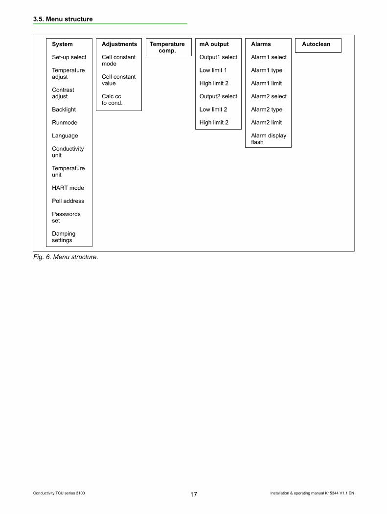
3.5. Menu structure
Temperaturecomp.
AutocleanSystem
Set-up select
Temperatureadjust
Contrastadjust
Backlight
Runmode
Language
Conductivityunit
Temperatureunit
HART mode
Poll address
Passwordsset
Dampingsettings
Adjustments
Cell constantmode
Cell constantvalue
Calc ccto cond.
mA output
Output1 select
Low limit 1
High limit 2
Output2 select
Low limit 2
High limit 2
Alarms
Alarm1 select
Alarm1 type
Alarm1 limit
Alarm2 select
Alarm2 type
Alarm2 limit
Alarm displayflash
Fig. 6. Menu structure.
Installation & operating manual K15344 V1.1 EN17Conductivity TCU series 3100
4. Maintenance & troubleshooting4.1. Cleaning the sensorCleaning may be necessary if deposits have built upto an extent that affects the cell constant of the elec-trode part.
When cleaning the sensor do not use hard materialto scrape or grind. Use a soft brush or cloth and asuitable cleaning remedy depending on the nature ofthe deposits. Be careful not to damage the electrodesas this might affect the accuracy of the sensor.
Chemical cleaning can be applied by using any re-agent that will not affect the sensor material. Sulphamicacid (NH2SO3H) is recommended. Use 250 g in 1 litreof water. Heat the water to ease dissolving. The solutioncan be used cold or warm.
Commercially available cleaning chemicals maycontain corrosion inhibitors, which can create an elec-trical isolating layer on the electrodes. This will resultin a high scaling signal after cleaning and a degradedperformance of the sensor.
List of usable cleaning acids for sensors. Insert formax. 2h at 30°C~ 86°F• Acetic acid CH3 COOH• Citric acid C3H4 (OH) (COOH)3
• Formic acid HCOOH• Lactic acid C3H4 (OH) COOH• Nitric acid HNO3
• Oxalic acid (COOH)2, max. 40% w/w• Phosphoric acid H3PO4
• Sulphamic acid NH2SO3H• Sulphuric acid H2SO4, max. 30% w/w• Tartaric acid C2H2 (OH)2 (COOH)2
WARNING: Do not use Hydrochloric acid (HCl) or Hydro-fluoric acid (HF)!
Installation & operating manual K15344 V1.1 EN18Conductivity TCU series 3100

4.2. Removing & mounting the sluice sensorRemoving (Fig. 1)Maximum pressure when removing: 5 bar.1. Unscrew the nut while holding back the sensor to
avoid a violent push-out.2. Let the sensor move out under control until the
stop.3. Close the ball valve.4. Unscrew the sensor from the sluice chamber.
L
Sensor type L(mm)4216 2484223 2284226 338
1.
2.
3.
4.
Fig. 1. Removing the sluice sensor.
Mounting (Fig. 2)1. Check the O-ring for damage before remounting
the sensor.2. Open the ball valve.3. Insert the sensor and tighten the 1" nut.
1.
2.
3.
O-ring
Fig. 2. Mounting the sluice sensor.
Installation & operating manual K15344 V1.1 EN19Conductivity TCU series 3100

4.3. Troubleshooting• Locate the problem to the monitor, the sensor,
sensor installation or to the electrical connections.If possible shift to another sensor or use a test probeto check the TCU.
• If the temperature reading is very wrong: CheckPt1000 in sensor for short circuit or interruption Thecheck can be done by resistance measurement fromthe sensor connector.
• Temperature reading partly wrong: This error mayarise from a poor thermal contact of the Pt1000element to the sensor structure. The thermal contactcan be checked by measuring the response time fora temperature change. Another source of error maybe the installation. The steel part of the sensor withthe reduced diameter is to be fully inserted in theprocess liquor flow.
• Conductivity/process value far out of range: Checkthe sensor cable for damage and check the sensorcable connection in the monitor for broken wires.
• Is the sensor tip surrounded with process liquor• Check the measuring section of the sensor for scal-
ing deposits and for electrode damages.• No reading in display: Check line voltage, fuses and
check that the connectors are in place.• Setting of the temperature compensation• Setting of analog output and accordance to setting
of analog input of DCS• Make a record of set-up info (Appendix A)
If help is required from factory please make a recordof the measurement display and the service display.This can be done with photos. Use backlight if possibleor illuminate the display from up or down in a 45° angleto avoid reflections (Fig. 3). Do not use flash.
Lamp
Camera
Fig. 3. Taking a photo of TCU displays.
Installation & operating manual K15344 V1.1 EN20Conductivity TCU series 3100

4.4. Spare partsThe TCU contains no wearing components.
Since the sensor is the most exposed part, havingspare sensors is recommended.Spare packings are recommended for the sensors:• For type 4221 and 4226 sensors:
15852 – Packing ring (4 pcs for each sensor)51393 – O-ring (3 pcs for each sensor)51338 – O-ring 44.2 x 3.0 for sluice sensor
• For type 4336–4339 sensors:160.91 – PTFE gasket with O-ring
• For type 4221–4225 sensors:156.55 – Gasket
4.5. Test equipmentTest probe, type 19041.• Pos. 1: Simulated temperature 90.1°C• Pos. 2: Simulated temperature 25°C
Pos. 1/2
Fig. 4. Test probe.
Fig. 5. Packing system, 4216 sensors.
Fig. 6. Packing system, 4223 and 4226 sensors.
Installation & operating manual K15344 V1.1 EN21Conductivity TCU series 3100
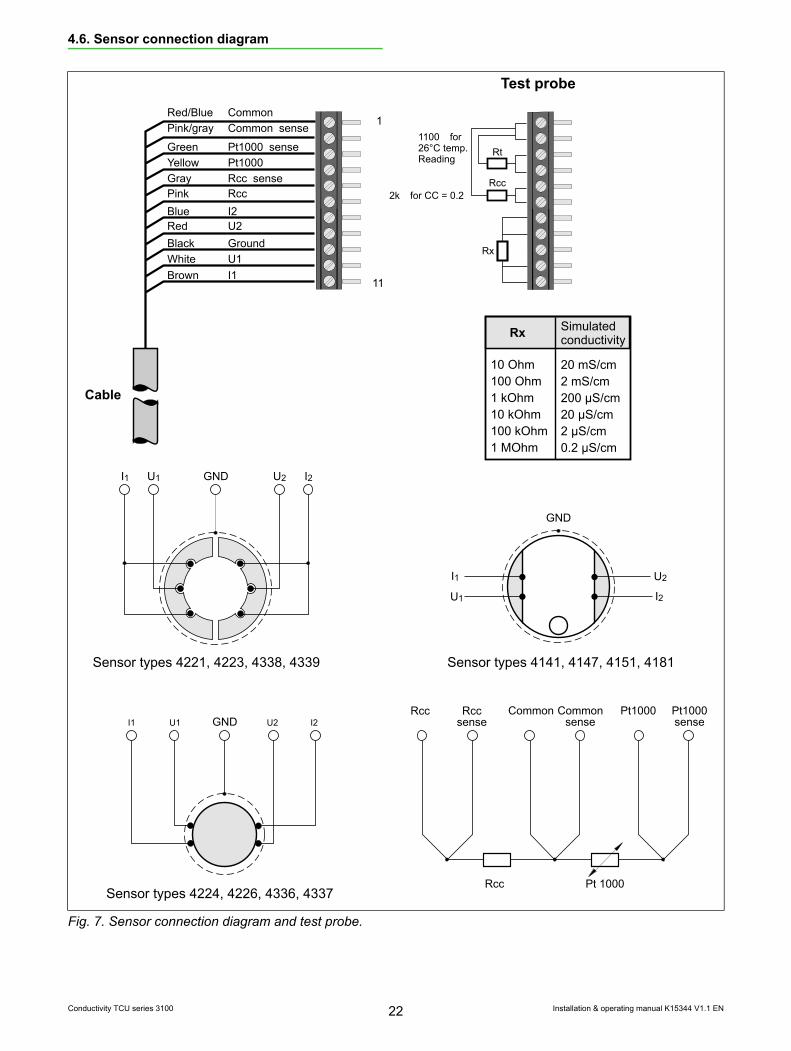
4.6. Sensor connection diagram
Cable
1
11
Pt 1000Rcc
CommonRccsense
Rcc Commonsense
Pt1000 Pt1000senseGNDI1 U1 U2 I2
I1 U1 GND U2 I2
Rx
Rx Simulatedconductivity
10 Ohm1001 k10 k100 k1 M
OhmOhm
OhmOhm
Ohm
20 mS/cm2 mS/cm200 µS/cm20 µS/cm2 µS/cm0.2 µS/cm
Test probe
I1
U1
U2
GND
I2
Sensor types 4141, 4147, 4151, 4181Sensor types 4221, 4223, 4338, 4339
Sensor types 4224, 4226, 4336, 4337
Pink/gray Common sense
Green Pt1000 senseYellow Pt1000Gray Rcc sensePink RccBlue I2Red U2Black GroundWhite U1Brown I1
Red/Blue Common
Rt
Rcc
1100 for26°C temp.Reading
2k for CC = 0.2
Fig. 7. Sensor connection diagram and test probe.
Installation & operating manual K15344 V1.1 EN22Conductivity TCU series 3100

3100
• Nomaintenance• Longlife• 4-electrodemeasuringprinciple• 13preprogrammedtemperaturecompensations• Widesensor-assortmentforallapplications• Lowinstallationcosts• Wideselectionofprocessmountingaccessories
Measurements for demanding applications
TheValmetConductivityinstrumentsmeasurehighandlowconductivityusingthe4-electrodeprinciple.Designedforconductivitycontrolinindustriessuchaspulp,power,pharmaceutical,food,brewery,sugarandchemical.
Fourindividuallyselectableset-upmodesareavail-able,twoforverylowconductivityandtwofornormal/highconductivity.
TheValmetConductivityinstrumentsaredesignedforveryhighprecisionandforalongandmainte-nance-freelife.
• Rugged • Accurate • Reliable
Valmet Conductivity Measurement

©ValmetCorpo
ratio
n,BR8143
0_EN
_0106/2015.
For more information, contact your local Valmet office. www.valmet.comSpecificationsinthisdocumentaresubjecttochangewithoutnotice.ProductnamesinthispublicationarealltrademarksofValmetCorporation.
SpecificationsLow conductivity set-up: Range0μS/cmto2S/cm(0μS/mto200S/m).Temperature compensation:O”, ultrapurewater (neutral,acid,alkaline,ammonia),STDsalt.High conductivity set-up: Range20μS/cmto2S/cm(2mS/mto200S/m)Temperature compensation: O”,STDsalt,weaklye, weakacidsOutput: Twocurrentoutputs4–20mAfor conductivityortemperature.Temperature measurement: From–40to+250°CDisplay: LCDSensor connection: Series4000sensorswith11-pole stripconnectorandMF20cableadaptorLocal or remote measuring range selection: Twolowandtwohighconductivityset-upmodesControl voltage: 12–30VDCHART®communicationasastandard
EnclosureMaterial: Castaluminium,PEcoatedProtection: IP67Dimensions: 144x144x107mmMounting: Panel,wallorpipeAmbient temp.: From-10to+60°CStorage temp.: From–20to+70°CWeight: 2.3kg
Wall mounting Type3107H Type3117H Panel mounting Type3108H Type3118H Power supply Looppowered Linepowered 18–30VDC 85–265VAC, onmA1 6VA Alarm Noalarm Tworelays 250VAC,8A Display Non- Illuminated illuminated
Sensors for serie 3100Series4200IndustrialapplicationsSeries4100Sanitaryapplications
Dimensions in mm
Mounting optionsWall Panel
Pipe
Pipe mounting kits Type Forpipe No. dimension 4902 a 25-38mm b 35-52mm c 50-73mm d 72-94mm e 82-114mm
For more information, contact your local Valmet office. www.valmet.com Specifications in this document are subject to change without notice. Product names in this publication are all trademarks of Valmet Corporation.©
Val
met
Cor
pora
tion,
D08
670
V1.
0 EN
11/
2016
Dimensions in mm
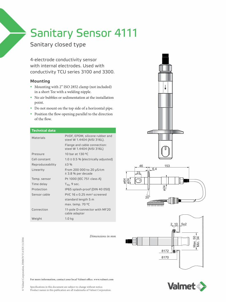
Sanitary closed type
Sanitary Sensor 4111
4-electrode conductivity sensor with internal electrodes. Used with conductivity TCU series 3100 and 3300.
Technical data
Materials PVDF, EPDM, silicone rubber and steel W 1.4404 (AISI 316L).
Flange and cable connection: steel W 1.4404 (AISI 316L)
Pressure 10 bar at 130 °C
Cell constant 1.0 ± 0.5 % (electrically adjusted)
Reproduceability ±3 %
Linearity From 200 000 to 20 μS/cm ± 3.8 % per decade
Temp. sensor Pt 1000 (IEC 751 class A)
Time delay T90, 9 sec.
Protection IP65 splash-proof (DIN 40 050)
Sensor cable PVC 16 x 0.25 mm2 screened
standard length 5 m
max. temp. 70 °C
Connection 11-pole D-connector with MF20 cable adapter
Weight 1.0 kg
46 153
236.4
2 10 5±2
8172
8170
ø64
ø24
ø24
20°M
ax. 5
0M
in. 3
4
Mounting• Mounting with 2” ISO 2852 clamp (not included)
in a short Tee with a welding nipple.• No air bubbles or sedimentation at the installation
point.• Do not mount on the top side of a horizontal pipe.• Position the flow opening parallel to the direction
of the flow.
For more information, contact your local Valmet office. www.valmet.com Specifications in this document are subject to change without notice. Product names in this publication are all trademarks of Valmet Corporation.©
Val
met
Cor
pora
tion,
D07
713
V1.
1 EN
06/
2016
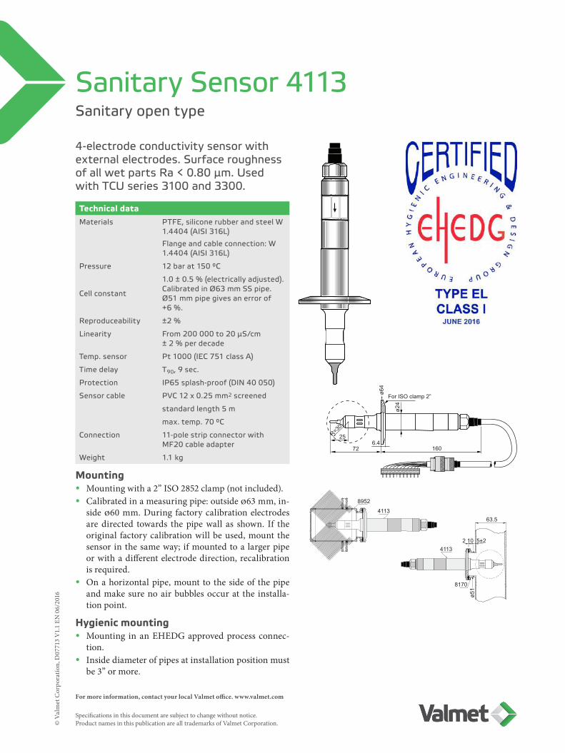
Sanitary open type
Sanitary Sensor 4113
4-electrode conductivity sensor with external electrodes. Surface roughness of all wet parts Ra < 0.80 μm. Used with TCU series 3100 and 3300.
Technical dataMaterials PTFE, silicone rubber and steel W
1.4404 (AISI 316L)
Flange and cable connection: W 1.4404 (AISI 316L)
Pressure 12 bar at 150 °C
Cell constant
1.0 ± 0.5 % (electrically adjusted). Calibrated in Ø63 mm SS pipe. Ø51 mm pipe gives an error of +6 %.
Reproduceability ±2 %
Linearity From 200 000 to 20 μS/cm ± 2 % per decade
Temp. sensor Pt 1000 (IEC 751 class A)
Time delay T90, 9 sec.
Protection IP65 splash-proof (DIN 40 050)
Sensor cable PVC 12 x 0.25 mm2 screened
standard length 5 m
max. temp. 70 °C
Connection 11-pole strip connector with MF20 cable adapter
Weight 1.1 kg
Mounting• Mounting with a 2” ISO 2852 clamp (not included).• Calibrated in a measuring pipe: outside Ø63 mm, in-
side Ø60 mm. During factory calibration electrodes are directed towards the pipe wall as shown. If the original factory calibration will be used, mount the sensor in the same way; if mounted to a larger pipe or with a different electrode direction, recalibration is required.
• On a horizontal pipe, mount to the side of the pipe and make sure no air bubbles occur at the installa-tion point.
Hygienic mounting• Mounting in an EHEDG approved process connec-
tion. • Inside diameter of pipes at installation position must
be 3” or more.
63.5
41132 10 5±2
8170
ø51
8952
4113
R=30
25
72 1606.4
ø64
For ISO clamp 2”ø2
4

89514113s
4113s
8170
ø51
ø24
ø64
For ISO clamp 2”
16072 6.424
.3
Pharmaceutical sanitary open type for ultrapure injection water
Sanitary Sensor 4113s
4-electrode conductivity sensor with external electrodes. Surface roughness of all wet parts Ra < 0.80 μm. Used with TCU series 3100 and 3300.
Technical data
Materials PTFE, silicone rubber and steel W 1.4404 (AISI 316L)
Pressure 12 bar at 150 °C
Cell constant
1.0 ± 0.5 % (electrically adjusted)
Calibrated in a Ø51 mm SS pipe.
Ø63 mm SS pipe gives an error of ~ -6 %.
Ø63 mm plastic pipe gives an er-ror of ~ 20–30 %.
Reproduceability ±2 %
Linearity From 20000 to 0.2 μS/cm ± 2 % per decade.
Below 5 μS/cm + 0.01 μS/cm.
Temp. sensor Pt 1000 (IEC 751 class A)
Time delay T90, 9 sec.
Protection IP65 splash-proof (DIN 40 050)
Sensor cable PVC 12 x 0.25 mm2
standard length 3 m
max. temp. 70 °C
Can optionally be mounted with 5 m cable; measuring below 0.5 μS/cm with this cable length is not recommended.
Connection 11-pole strip connector with MF20 cable adapter
Weight 0.6 kg
dimensions in millimeters
Typical mounting
Mounting• Mountingwitha2”ISO2852clamp(notincluded).• Minimumdistancetosurroundings:24.3mm.• Whenmountingonahorizontalpipe,mounttothe
sideofthepipeandmakesurenoairbubblesoccurattheinstallationpoint.
• Constructthepipinginaself-drainingmanner.
For more information, contact your local Valmet office. www.valmet.com Specifications in this document are subject to change without notice. Product names in this publication are all trademarks of Valmet Corporation.©
ValmetCorpo
ratio
n,D07726V1.1EN
06/2016
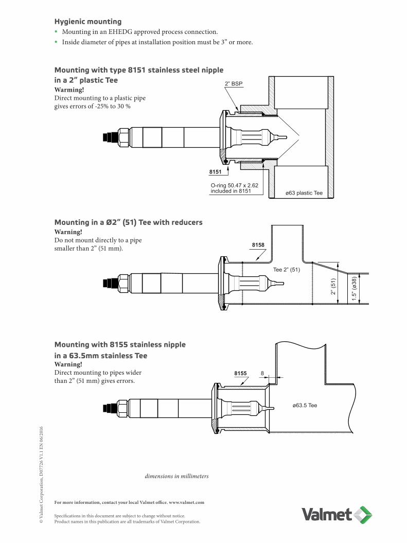
2” BSP
8151
ø63 plastic TeeO-ring 50.47 x 2.62included in 8151
8158
Tee 2” (51)
1.5”
(ø38
)
2” (5
1)
8155 8
ø63.5 Tee
Mounting with type 8151 stainless steel nipple in a 2” plastic TeeWarming!Directmountingtoaplasticpipegiveserrorsof-25%to30%
Mounting with 8155 stainless nipple in a 63.5mm stainless TeeWarning!Directmountingtopipeswiderthan2”(51mm)giveserrors.
Mounting in a Ø2” (51) Tee with reducersWarning!Donotmountdirectlytoapipesmallerthan2”(51mm).
Hygienic mounting• MountinginanEHEDGapprovedprocessconnection.• Insidediameterofpipesatinstallationpositionmustbe3”ormore.
dimensions in millimeters

For more information, contact your local Valmet office. www.valmet.com Specifications in this document are subject to change without notice. Product names in this publication are all trademarks of Valmet Corporation.
4115
8170
2 10
diam
. 51
5 ± 2
L = 220 6.4 160
diam
.64
diam
.24
For ISO clamp 2”
25R=30
Sanitary open type sensor
Sanitary Sensor 4115
4-electrode conductivity sensor with external electrodes. Used with TCU series 3100 and 3300.
Typical mounting• Mountingwith2”ISO2852clamp(notincluded).• Calibratedinadiam.180mmvessel;ifthesensor
willbemountedinapipesmallerthan100mmindiameter,recalibrationisrequired.
• Noairbubblesorsedimentationattheinstallationpoint.
• Donotmountonthetopsideofahorizontalpipe.
Technical data
Length 0.25 m or extended to 0.5 / 1.0 / 1.5 / 2.0 / 2.5 m
Materials, sensor PTFE, silicone rubber and steel W 1.4404 (AISI 316L)
Materials, flange & cable connection W1.4404 (AISI 316L)
Pressure max. 12 bar at 150 °C
Cell constant 1.0 ± 0.5% (electrically adjusted)
Reproduceability ± 2%
Linearity 200 000 to 20 μS/cm ±2% per decade
Temp. sensor Pt 1000 (IEC 751 class A)
Time delay T90, 9 sec.
Protection IP65 splash-proof (DIN 40 050)
Sensor cable PVC 12 x 0.25 mm2 screened
standard length 5 m
max. temp. 70 °C
Connection 11-pole strip connector with MF20 cable adapter
Weight 1.2 kg
dimensions in millimeters
©ValmetCorpo
ratio
n,D07438V1.0EN
04/2015
For more information, contact your local Valmet office. www.valmet.com Specifications in this document are subject to change without notice. Product names in this publication are all trademarks of Valmet Corporation.
0.63”(16) 3” (76)
min. 2.48”(63)
6.42” (163)0.31”(8)
1”(25)2.72”
(69)
3.05
”(7
7.5)
0.96
”(ø
24.5
) R:0.26”(6.5)
For ISO clamp 2½”20°
3-A sanitary open type
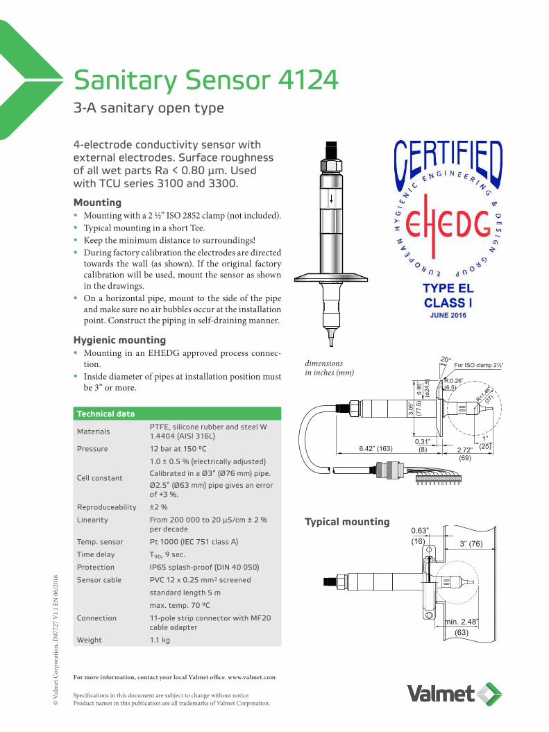
Sanitary Sensor 4124
4-electrode conductivity sensor with external electrodes. Surface roughness of all wet parts Ra < 0.80 μm. Used with TCU series 3100 and 3300.
Mounting• Mountingwitha2½”ISO2852clamp(notincluded).• TypicalmountinginashortTee.• Keeptheminimumdistancetosurroundings!• Duringfactorycalibrationtheelectrodesaredirected
towards thewall (as shown). If the original factorycalibrationwillbeused,mountthesensorasshowninthedrawings.
• Onahorizontalpipe,mount to thesideof thepipeandmakesurenoairbubblesoccurattheinstallationpoint.Constructthepipinginself-drainingmanner.
Hygienic mounting• Mounting in anEHEDGapprovedprocess connec-
tion.• Insidediameterofpipesatinstallationpositionmust
be3”ormore.
Technical data
Materials PTFE, silicone rubber and steel W 1.4404 (AISI 316L)
Pressure 12 bar at 150 °C
Cell constant
1.0 ± 0.5 % (electrically adjusted)
Calibrated in a Ø3” (Ø76 mm) pipe.
Ø2.5” (Ø63 mm) pipe gives an error of +3 %.
Reproduceability ±2 %
Linearity From 200 000 to 20 μS/cm ± 2 % per decade
Temp. sensor Pt 1000 (IEC 751 class A)
Time delay T90, 9 sec.
Protection IP65 splash-proof (DIN 40 050)
Sensor cable PVC 12 x 0.25 mm2 screened
standard length 5 m
max. temp. 70 °C
Connection 11-pole strip connector with MF20 cable adapter
Weight 1.1 kg
Typical mounting
dimensionsin inches (mm)
©ValmetCorpo
ratio
n,D07727V1.1EN
06/2016
For more information, contact your local Valmet office. www.valmet.com Specifications in this document are subject to change without notice. Product names in this publication are all trademarks of Valmet Corporation.©
Val
met
Cor
pora
tion,
D07
712
V1.
1 EN
06/
2016
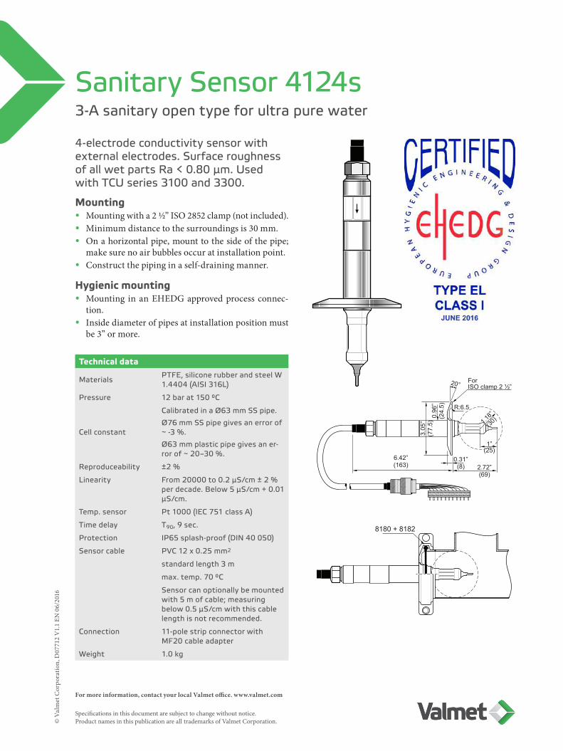
3-A sanitary open type for ultra pure water
Sanitary Sensor 4124s
4-electrode conductivity sensor with external electrodes. Surface roughness of all wet parts Ra < 0.80 μm. Used with TCU series 3100 and 3300.
Mounting• Mounting with a 2 ½” ISO 2852 clamp (not included).• Minimum distance to the surroundings is 30 mm. • On a horizontal pipe, mount to the side of the pipe;
make sure no air bubbles occur at installation point.• Construct the piping in a self-draining manner.
Hygienic mounting• Mounting in an EHEDG approved process connec-
tion. • Inside diameter of pipes at installation position must
be 3” or more.
Technical data
Materials PTFE, silicone rubber and steel W 1.4404 (AISI 316L)
Pressure 12 bar at 150 °C
Cell constant
Calibrated in a Ø63 mm SS pipe.
Ø76 mm SS pipe gives an error of ~ -3 %.
Ø63 mm plastic pipe gives an er-ror of ~ 20–30 %.
Reproduceability ±2 %
Linearity From 20000 to 0.2 μS/cm ± 2 % per decade. Below 5 μS/cm + 0.01 μS/cm.
Temp. sensor Pt 1000 (IEC 751 class A)
Time delay T90, 9 sec.
Protection IP65 splash-proof (DIN 40 050)
Sensor cable PVC 12 x 0.25 mm2
standard length 3 m
max. temp. 70 °C
Sensor can optionally be mounted with 5 m of cable; measuring below 0.5 μS/cm with this cable length is not recommended.
Connection 11-pole strip connector with MF20 cable adapter
Weight 1.0 kg
8180 + 8182
6.42”(163)
3.05
”(7
7.5)
0.96
”(2
4.5)
2.72”(69)
0.31”(8)
R:6.5
1.18”
(30)
1”(25)
20° For ISO clamp 2 ½”

For more information, contact your local Valmet office. www.valmet.com Specifications in this document are subject to change without notice. Product names in this publication are all trademarks of Valmet Corporation.©
Val
met
Cor
pora
tion,
D07
728
V1.
0 EN
04/
2015
158 51
35
237.5
ø50
ø24
min. 38
SMS38
h b
Sanitary closed type
Sanitary Sensor 4131
4-electrode conductivity sensor with internal electrodes. Universal flange for SMS38, DIN DN32 and 40 union. Used with TCU series 3100 and 3300.
MountingSensor mounting in a short Tee with a welding male part. Can be mounted on vertical or horizontal pipes in all directions; on a horizontal pipe mounting to the side or under the pipe. Flow opening must be parallel to the flow direction. An arrow on the sensor indicates the position of the temperature sensor. Mount in a place where no air pockets or bubbles occur.
Technical data
Materials, sensor PVDF, EPDM, silicone rubber and steel W 1.4404 (AISI 316L)
Flange & cable connection Steel W 1.4404 (AISI 316L)
Temperature sensor Coated with PFA
Pressuremax. 10 bar at 130 °C
(150 °C < 1h)
Cell constant 1.0 ± 0.5 % (electrically adjusted)
Reproduceability ±2 %
Linearity From 200 000 to 1 μS/cm ± 2 % per decade
Temp. sensor Pt 1000 (IEC 751 class A)
Time delay T90, 9 sec.
Protection IP65 splash-proof (DIN 40 050)
Sensor cable PVC 12 x 0.25 mm2 screened
standard length 5 m
max. temp. 70 °C
Connection 11-pole strip connector with MF20 cable adapter
Weight 1.0 kg
AccessoriesSMS38 DN32 DN40
Union nut 8270 8370 8470
Nipple with gasket 8285 8385 8485
Nipple height (h) 22 mm 16.5 mm 16.5 mm
Nipple diameter 60 58 65
Tee branch length (b) 4 mm 8 mm 8 mm
Typical mounting
dimensions in mm

For more information, contact your local Valmet office. www.valmet.com Specifications in this document are subject to change without notice. Product names in this publication are all trademarks of Valmet Corporation.©
Val
met
Cor
pora
tion,
D08
672
V1.
0 EN
11/
2016
R=37
140 L65
257.5
ø50
R=37
ø25
Sanitary open type
Sanitary Sensor 4135
4-electrode conductivity sensor with external electrodes. Used with conductivity TCU series 3100 and 3300. Universal flange for SMS38, DIN DN32 and 40 union.
MountingMounting requires a welding nipple. Sensor can be mounted in any direction. Keep the minimum distance (R = 37 mm) to the surroundings!Mount the sensor in a place where no air pockets or bubbles occur.
Technical data
Length L = 220 mm or to be specified, max. 2.5 m
Materials PTFE, silicone rubber and steel W 1.4404 (AISI 316L).
Pressure 12 bar at 150 °C
Cell constant1.0 ± 0.5 % (electrically adjusted)
Calibrated in an open vessel
Reproduceability ±2 %
Linearity From 200 000 to 20 μS/cm ± 2 % per decade
Temp. sensor Pt 1000 (IEC 751 class A)
Time delay T90, 9 sec.
Protection IP65 splash-proof (DIN 40 050)
Sensor cable PVC 16 x 0.25 mm2 screened
standard length 5 m
max. temp. 70 °C
Connection 11-pole strip connector with MF20 cable adapter
Weight 0.9 kg
Dimensions in mm
Typical mounting
Accessories SMS38 DN32 DN40Union nut 8270 8370 8470
Nipple with gasket 8285 8385 8485
Nipple height (h) 22 mm 16.5 mm 16.5 mm
Nipple diameter 60 58 65

For more information, contact your local Valmet office. www.valmet.com Specifications in this document are subject to change without notice. Product names in this publication are all trademarks of Valmet Corporation.©
Val
met
Cor
pora
tion,
D07
736
V1.
0 EN
04/
2015
15356.5
4141
6.4
35
23
20° ø24
ø24
ø64
67
38
4141
8806
ø63
Sanitary closed type
Sanitary Sensor 4141
4-electrode conductivity sensor with internal electrodes. Suitable for acetone applications. Used with TCU series 3100 and 3300.
MountingSensor mounting with a 2” ISO 2852 clamp (not included). When mounting on a horizontal pipe, mount on the side and in a place where no air pockets or bubbles occur. The flow opening should be parallel to the direction of the flow. Construct the piping in a self-draining manner.
Technical data
Materials PVDF, EPDM, silicone rubber and steel W 1.4404 (AISI 316L)
Temperature sensor Coated with PFA
Pressuremax. 10 bar at 130 °C
(150 °C < 1h)
Cell constant 1.0 ± 0.5 % (electrically adjusted)
Reproduceability ± 2 %
Linearity From 200 000 to 1 μS/cm ± 2 % per decade;
below 5 μS/cm + 0.01 μS/cm
Temp. sensor Pt 1000 (IEC 751 class A)
Time delay T90, 9 sec.
Protection IP65 splash-proof (DIN 40 050)
Sensor cable PVC 12 x 0.25 mm2 screened
Standard length 5 m
Sensor can optionally be mount-ed with 3 m or 15 m of cable.
Measuring below 0.2 μS/cm with 3 m cable is not recommended.
Do not measure below 5 μS/cm with 15 m cable.
max. temp. 70 °C
Connection 11-pole strip connector with MF20 cable adapter
Weight 1.0 kg
Typical mounting
dimensions in mm

For more information, contact your local Valmet office. www.valmet.com Specifications in this document are subject to change without notice. Product names in this publication are all trademarks of Valmet Corporation.©
Val
met
Cor
pora
tion,
D07
737
V1.
0 EN
04/
2015
15356.56.4
35
23
20° ø24
ø24
ø64
38
67
38
81728170
8806
ø63ø51
ø38
Sanitary closed type – non-standard item
Sanitary Sensor 4141 PES
4-electrode conductivity sensor with internal electrodes. Used with TCU series 3100 and 3300.
MountingSensor mounting with a 2” ISO 2852 clamp (not included) to a short Tee with a welding nipple. The sensor can be mounted in pipes of all directions; do not mount on the upper side of a horizontal pipe.Mount in a place where no air bubbles or sedimenta-tion occur. The flow opening should be parallel to the direction of the flow. An arrow on the sensor indicates the position of the temperature sensor.
Technical dataMaterials PES, EPDM, silicone rubber and
steel W 1.4404 (AISI 316L).
Flange and cable connection: steel W 1.4404 (AISI 316L)
Pressure max. 12 bar at 150 °C
Cell constant 1.0 ± 0.5 % (electrically adjusted)
Reproduceability ± 2 %
Linearity From 200 000 to 1 μS/cm ± 2 % per decade
Temp. sensor Pt 1000 (IEC 751 class A)
Time delay T90, 9 sec.
Protection IP65 splash-proof (DIN 40 050)
Sensor cable PVC 12 x 0.25 mm2 screened
Standard length 5 m
max. temp. 70 °C
Connection 11-pole strip connector with MF20 cable adapter
Weight 1.0 kg
Typical mounting
dimensions in mm
For more information, contact your local Valmet office. www.valmet.com Specifications in this document are subject to change without notice. Product names in this publication are all trademarks of Valmet Corporation.©
Val
met
Cor
pora
tion,
D07
730
V1.
0 EN
04/
2015
44 153
ø23.
5
ø64
ø24
50
5
0
33
15.5
2” clamp
22.5
R=0.8±0.1
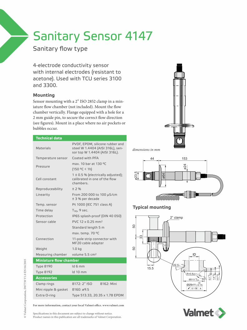
Sanitary flow type
Sanitary Sensor 4147
4-electrode conductivity sensor with internal electrodes (resistant to acetone). Used with TCU series 3100 and 3300.
MountingSensor mounting with a 2” ISO 2852 clamp in a min-iature flow chamber (not included). Mount the flow chamber vertically. Flange equipped with a hole for a 2 mm guide pin, to secure the correct flow direction (see figures). Mount in a place where no air pockets or bubbles occur.
Technical data
MaterialsPVDF, EPDM, silicone rubber and steel W 1.4404 (AISI 316L), sen-sor top W 1.4404 (AISI 316L).
Temperature sensor Coated with PFA
Pressuremax. 10 bar at 130 °C
(150 °C < 1h)
Cell constant1 ± 0.5 % (electrically adjusted); calibrated in one of the flow chambers.
Reproduceability ± 2 %
Linearity From 200 000 to 100 μS/cm ± 3 % per decade
Temp. sensor Pt 1000 (IEC 751 class A)
Time delay T90, 9 sec.
Protection IP65 splash-proof (DIN 40 050)
Sensor cable PVC 12 x 0.25 mm2
Standard length 5 m
max. temp. 70 °C
Connection 11-pole strip connector with MF20 cable adapter
Weight 1.0 kg
Measuring chamber volume 5.5 cm2
Miniature flow chamberType 8190 ld 6 mm
Type 8192 ld 10 mm
AccessoriesClamp rings 8172: 2” ISO 8162: Mini
Mini nipple & gasket 8160: Ø9.5
Extra O-ring Type 513.33, 20.35 x 1.78 EPDM
Typical mounting
dimensions in mm
For more information, contact your local Valmet office. www.valmet.com Specifications in this document are subject to change without notice. Product names in this publication are all trademarks of Valmet Corporation.©
Val
met
Cor
pora
tion,
D07
729
V1.
0 EN
04/
2015
min. 35
(R=6.5)
min. 50
167 19 44
23
ø84 ø68
ø24
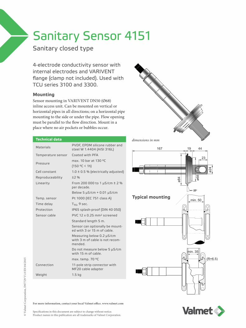
Sanitary closed type
Sanitary Sensor 4151
4-electrode conductivity sensor with internal electrodes and VARIVENT flange (clamp not included). Used with TCU series 3100 and 3300.
MountingSensor mounting in VARIVENT DN50 (Ø68)inline access unit. Can be mounted on vertical or horizontal pipes in all directions; on a horizontal pipe mounting to the side or under the pipe. Flow opening must be parallel to the flow direction. Mount in a place where no air pockets or bubbles occur.
Technical data
Materials PVDF, EPDM silicone rubber and steel W 1.4404 (AISI 316L)
Temperature sensor Coated with PFA
Pressuremax. 10 bar at 130 °C
(150 °C < 1h)
Cell constant 1.0 ± 0.5 % (electrically adjusted)
Reproduceability ±2 %
Linearity From 200 000 to 1 μS/cm ± 2 % per decade.
Below 5 μS/cm + 0.01 μS/cm
Temp. sensor Pt 1000 (IEC 751 class A)
Time delay T90, 9 sec.
Protection IP65 splash-proof (DIN 40 050)
Sensor cable PVC 12 x 0.25 mm2 screened
Standard length 5 m.
Sensor can optionally be mount-ed with 3 or 15 m of cable.
Measuring below 0.2 μS/cm with 3 m of cable is not recom-mended.
Do not measure below 5 μS/cm with 15 m of cable.
max. temp. 70 °C
Connection 11-pole strip connector with MF20 cable adapter
Weight 1.5 kg
Typical mounting
dimensions in mm
For more information, contact your local Valmet office. www.valmet.com Specifications in this document are subject to change without notice. Product names in this publication are all trademarks of Valmet Corporation.©
Val
met
Cor
pora
tion,
D08
310
V1.
0 EN
06/
2016
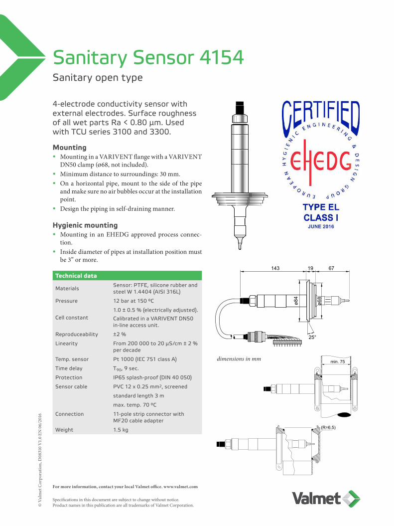
Sanitary open type
Sanitary Sensor 4154
4-electrode conductivity sensor with external electrodes. Surface roughness of all wet parts Ra < 0.80 μm. Used with TCU series 3100 and 3300.
Mounting• Mounting in a VARIVENT flange with a VARIVENT
DN50 clamp (Ø68, not included).• Minimum distance to surroundings: 30 mm.• On a horizontal pipe, mount to the side of the pipe
and make sure no air bubbles occur at the installation point.
• Design the piping in self-draining manner.
Hygienic mounting• Mounting in an EHEDG approved process connec-
tion. • Inside diameter of pipes at installation position must
be 3” or more.
Technical data
Materials Sensor: PTFE, silicone rubber and steel W 1.4404 (AISI 316L)
Pressure 12 bar at 150 °C
Cell constant1.0 ± 0.5 % (electrically adjusted).
Calibrated in a VARIVENT DN50 in-line access unit.
Reproduceability ±2 %
Linearity From 200 000 to 20 μS/cm ± 2 % per decade
Temp. sensor Pt 1000 (IEC 751 class A)
Time delay T90, 9 sec.
Protection IP65 splash-proof (DIN 40 050)
Sensor cable PVC 12 x 0.25 mm2, screened
standard length 3 m
max. temp. 70 °C
Connection 11-pole strip connector with MF20 cable adapter
Weight 1.5 kg
dimensions in mm
143 19 67
ø84
ø68
25°
min. 75
(R=6.5)

For more information, contact your local Valmet office. www.valmet.com Specifications in this document are subject to change without notice. Product names in this publication are all trademarks of Valmet Corporation.©
Val
met
Cor
pora
tion,
D08
311
V1.
0 EN
06/
2016
min. 75
143 19 67
ø84
ø68
25°
25
30
min. 60
(R=6.5)
Pharmaceutical sanitary open type
Sanitary Sensor 4154s
4-electrode conductivity sensor with external electrodes. Surface roughness of all wet parts Ra < 0.80 μm. Used with TCU series 3100 and 3300.
Technical data
Materials Sensor: PTFE, silicone rubber and steel W 1.4404 (AISI 316L)
Pressure 12 bar at 150 °C
Cell constant1.0 ± 0.5 % (electrically adjusted).
Calibrated in a VARIVENT DN50 in-line access unit.
Reproduceability ±2 %
Linearity From 20 000 to 0.2 μS/cm ± 2 % per decade; below 5 μS/cm + 0.01 μS/cm
Temp. sensor Pt 1000 (IEC 751 class A)
Time delay T90, 9 sec.
Protection IP65 splash-proof (DIN 40 050)
Sensor cable PVC 12 x 0.25 mm2, screened
standard length 3 m
option: 5 m cable; measuring below 0.5 μS/cm with this cable length is not recommended
max. temp. 70 °C
Connection 11-pole strip connector with MF20 cable adapter
Weight 1.5 kg
Mounting• Mounting in a VARIVENT flange with a VARI-
VENT DN50 clamp (Ø68, not included).• Minimum distance to surroundings: 30 mm.• On a horizontal pipe, mount to the side of the pipe
and make sure no air bubbles occur at the installa-tion point.
• Design the piping in self-draining manner.
Hygienic mounting• Mounting in an EHEDG approved process connec-
tion. • Inside diameter of pipes at installation position
must be 3” or more.
dimensions in mm

For more information, contact your local Valmet office. www.valmet.com Specifications in this document are subject to change without notice. Product names in this publication are all trademarks of Valmet Corporation.©
Val
met
Cor
pora
tion,
D07
738
V1.
0 EN
04/
2015
302
8891
60ø10
54 40 63 14 1843 6.4
ø50.
5ø2
4
23
35
ø24
ø25
20°
UP54
ø38
40.5 21.5
ø44
ø50
41818805
9 31
Sanitary closed type
Sanitary Sensor 4181
4-electrode conductivity sensor with internal electrodes. Used with TCU series 3100 and 3300.
MountingSensor mounting with a 1.5” ISO 2852 clamp (not included). When mounting on a horizontal pipe, mount to the side of the pipe and in a place where no air bubbles occur. The flow opening should be parallel to the direction of the flow. Construct the piping in a self-draining manner.
Technical dataMaterials PVDF, EPDM, silicone rubber and
steel W 1.4404 (AISI 316L).
Temperature sensor coated with PFA
Pressure max. 10 bar at 130 °C
(150 °C < 1h)
Cell constant 1.0 ± 0.5 % (electrically adjusted)
Calibrated in SS pipe.
Reproduceability ± 2 %
Linearity In SS pipe from 1 μS/cm to 10.000 μS/cm ± 2 % per decade;
from 10.00 μS/cm to 200.000 μS/cm error + 5 % per decade
Temp. sensor Pt 1000 (IEC 751 class A)
Time delay T90, 9 sec.
Protection IP65 splash-proof (DIN 40 050)
Sensor cable PVC 12 x 0.25 mm2 screened
Standard length 5 m.
Sensor can optionally be mount-ed with 3 m or 15 m of cable.
Measuring below 0.2 μS/cm with 3 m cable is not recommended.
Do not measure below 5 μS/cm with 15 m cable.
max. temp. 70 °C
Connection 11-pole strip connector with MF20 cable adapter
Weight 1.0 kg
Typical mounting
dimensions in mm
For more information, contact your local Valmet office. www.valmet.com Specifications in this document are subject to change without notice. Product names in this publication are all trademarks of Valmet Corporation.©
Val
met
Cor
pora
tion,
D07
739
V1.
1 EN
06/
2016
NAV 1-1
1 ½” ISO
L=85
37
4 10
147
For ISO clamp 1 ½”
85
6.435R=37
ø50.
5
ø24
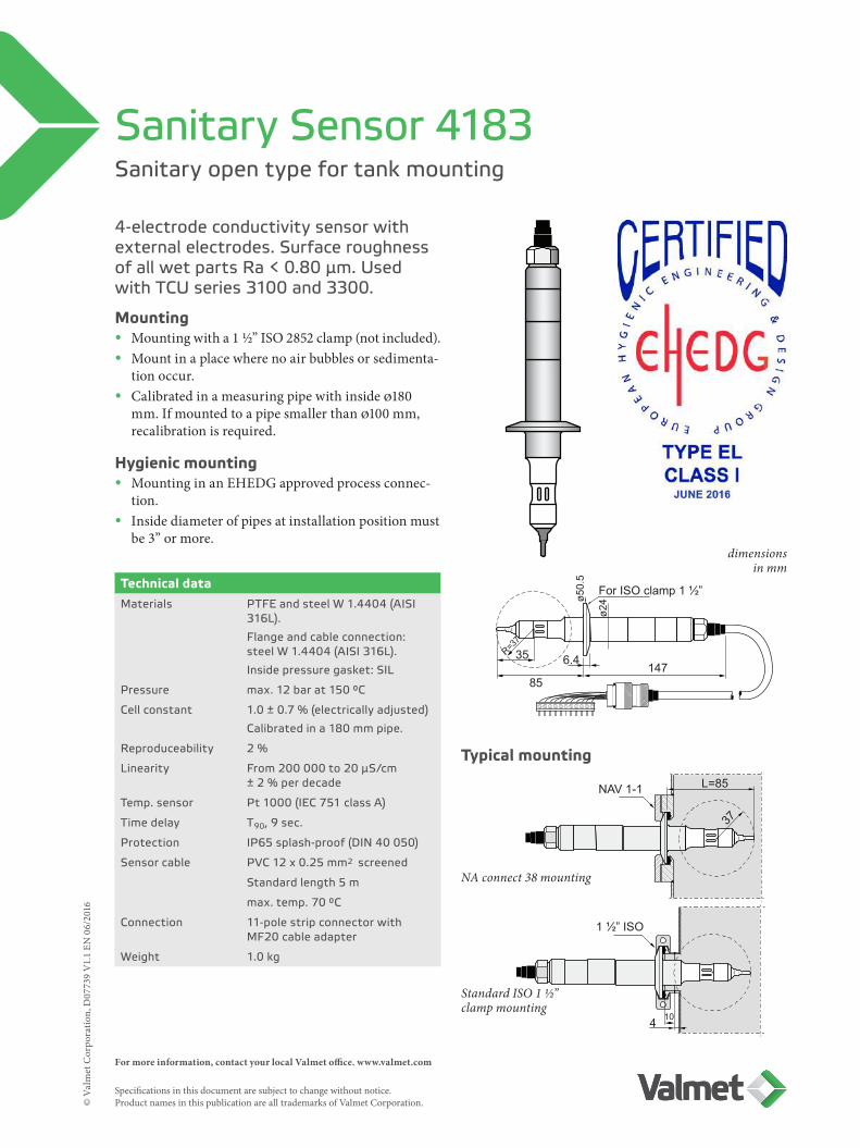
Sanitary open type for tank mounting
Sanitary Sensor 4183
4-electrode conductivity sensor with external electrodes. Surface roughness of all wet parts Ra < 0.80 μm. Used with TCU series 3100 and 3300.
Mounting• Mounting with a 1 ½” ISO 2852 clamp (not included).• Mount in a place where no air bubbles or sedimenta-
tion occur. • Calibrated in a measuring pipe with inside Ø180
mm. If mounted to a pipe smaller than Ø100 mm, recalibration is required.
Hygienic mounting• Mounting in an EHEDG approved process connec-
tion. • Inside diameter of pipes at installation position must
be 3” or more.
Technical dataMaterials PTFE and steel W 1.4404 (AISI
316L).
Flange and cable connection: steel W 1.4404 (AISI 316L).
Inside pressure gasket: SIL
Pressure max. 12 bar at 150 °C
Cell constant 1.0 ± 0.7 % (electrically adjusted)
Calibrated in a 180 mm pipe.
Reproduceability 2 %
Linearity From 200 000 to 20 μS/cm ± 2 % per decade
Temp. sensor Pt 1000 (IEC 751 class A)
Time delay T90, 9 sec.
Protection IP65 splash-proof (DIN 40 050)
Sensor cable PVC 12 x 0.25 mm2 screened
Standard length 5 m
max. temp. 70 °C
Connection 11-pole strip connector with MF20 cable adapter
Weight 1.0 kg
Typical mounting
dimensions in mm
NA connect 38 mounting
Standard ISO 1 ½”clamp mounting
For more information, contact your local Valmet office. www.valmet.com Specifications in this document are subject to change without notice. Product names in this publication are all trademarks of Valmet Corporation.©
Val
met
Cor
pora
tion,
D08
070
V1.
1 EN
06/
2016
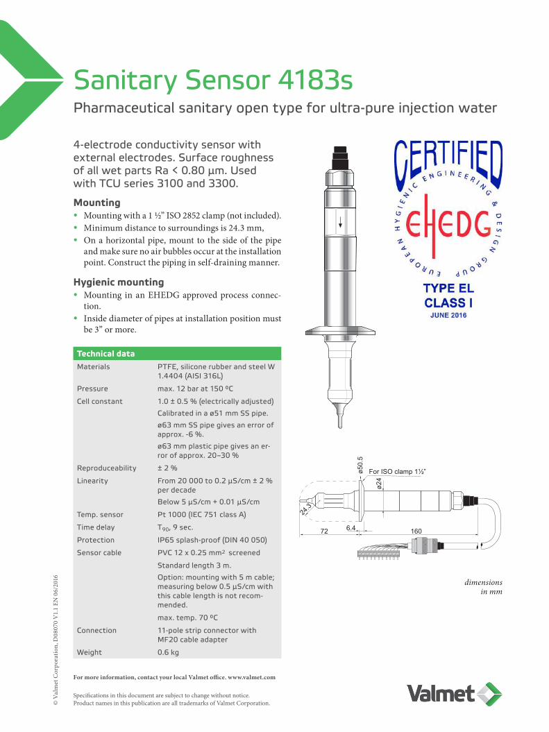
Pharmaceutical sanitary open type for ultra-pure injection water
Sanitary Sensor 4183s
4-electrode conductivity sensor with external electrodes. Surface roughness of all wet parts Ra < 0.80 μm. Used with TCU series 3100 and 3300.
Mounting• Mounting with a 1 ½” ISO 2852 clamp (not included). • Minimum distance to surroundings is 24.3 mm,• On a horizontal pipe, mount to the side of the pipe
and make sure no air bubbles occur at the installation point. Construct the piping in self-draining manner.
Hygienic mounting• Mounting in an EHEDG approved process connec-
tion. • Inside diameter of pipes at installation position must
be 3” or more.
Technical dataMaterials PTFE, silicone rubber and steel W
1.4404 (AISI 316L)
Pressure max. 12 bar at 150 °C
Cell constant 1.0 ± 0.5 % (electrically adjusted)
Calibrated in a Ø51 mm SS pipe.
Ø63 mm SS pipe gives an error of approx. -6 %.
Ø63 mm plastic pipe gives an er-ror of approx. 20–30 %
Reproduceability ± 2 %
Linearity From 20 000 to 0.2 μS/cm ± 2 % per decade
Below 5 μS/cm + 0.01 μS/cm
Temp. sensor Pt 1000 (IEC 751 class A)
Time delay T90, 9 sec.
Protection IP65 splash-proof (DIN 40 050)
Sensor cable PVC 12 x 0.25 mm2 screened
Standard length 3 m.
Option: mounting with 5 m cable; measuring below 0.5 μS/cm with this cable length is not recom-mended.
max. temp. 70 °C
Connection 11-pole strip connector with MF20 cable adapter
Weight 0.6 kg
dimensions in mm
For ISO clamp 1½”
72 160
ø50.
5
ø24
6.4
24.3

For more information, contact your local Valmet office. www.valmet.com Specifications in this document are subject to change without notice. Product names in this publication are all trademarks of Valmet Corporation.©
Val
met
Cor
pora
tion,
D07
740
V1.
0 EN
04/
2015
NAV 1-1 L=150
1 ½” ISO
37
104
For ISO clamp 1 ½”
R=37
150 34 63 14 186.435
ø50.
5
ø24
Sanitary open type for tank mounting
Sanitary Sensor 4185
4-electrode conductivity sensor with external electrodes. Wet steel parts of sensor polished to Ra<0.8 μm, PTFE part to Ra<1.2 μm. Used with TCU series 3100 and 3300.
MountingSensor mounting with a 1 ½” ISO 2852 clamp (not included). Mount in a place where no air bubbles or sedimentation occur. The sensor has been calibrated in a measuring pipe with inside Ø180 mm. If the sensor will be mounted to a pipe smaller than Ø100 mm, recalibration is required.
Technical dataMaterials PTFE and steel W 1.4404 (AISI
316L).
Flange and cable connection: steel W 1.4404 (AISI 316L).
Inside pressure gasket: SIL
Pressure max. 12 bar at 150 °C
Cell constant 1.0 ± 0.7 % (electrically adjusted)
Calibrated in a 180 mm pipe.
Reproduceability ± 2 %
Linearity From 200 000 to 20 μS/cm ± 2 % per decade
Temp. sensor Pt 1000 (IEC 751 class A)
Time delay T90, 9 sec.
Protection IP65 splash-proof (DIN 40 050)
Sensor cable PVC 12 x 0.25 mm2 screened
Standard length 5 m
max. temp. 70 °C
Connection 11-pole strip connector with MF20 cable adapter
Weight 1.2 kg
Typical mounting
dimensions in mm
NA connect 38 mounting
Standard ISO 1 ½”clamp mounting

For more information, contact your local Valmet office. www.valmet.com Specifications in this document are subject to change without notice. Product names in this publication are all trademarks of Valmet Corporation.©
Val
met
Cor
pora
tion,
D07
743
V1.
0 EN
04/
2015
40
BS
P 1
¼”
4194
8977
R=30
131 L210 66L1
33
30 8905
R=30
254.5
ø36
ø25
ø18.
5
Sanitary open types
Sanitary Sensors 4193 & 4194
4-electrode conductivity sensors with external electrodes, for use with BSP 1 ¼” Ingold nipple. Used with TCU series 3100 and 3300.
MountingSensor mounting with a 1 ¼” nut (included). Mount in a place where no air bubbles or sedimentation occur. Do not mount on the upper side of a horizontal pipe. If the sensor will be mounted to a small diamter pipe, recalibration is required.
Technical dataType 4193 L1 = 32 mm, L2 = 140 mm
Type 4194 L1 = 42 mm, L2 = 140 mm
Materials PTFE, silicone rubber, Viton O-ring and steel W 1.4404 (AISI 316L).
Flange and cable connection: steel W 1.4404 (AISI 316L).
Pressure max. 12 bar at 150 °C
Cell constant 1.0 ± 0.5 % (electrically adjusted)
Calibrated in an open vessel.
Reproduceability ± 2 %
Linearity From 200 000 to 20 μS/cm ± 2 % per decade
Temp. sensor Pt 1000 (IEC 751 class A)
Time delay T90, 9 sec.
Protection IP65 splash-proof (DIN 40 050)
Sensor cable PVC 12 x 0.25 mm2 screened
Standard length 5 m
max. temp. 70 °C
Connection 11-pole strip connector with MF20 cable adapter
Weight 1.5 kg
Typical mounting
dimensions in mm
Accessories
8977 Nipple
67 17 145
4
29.4
29
83
diam
. 3
diam
. 30
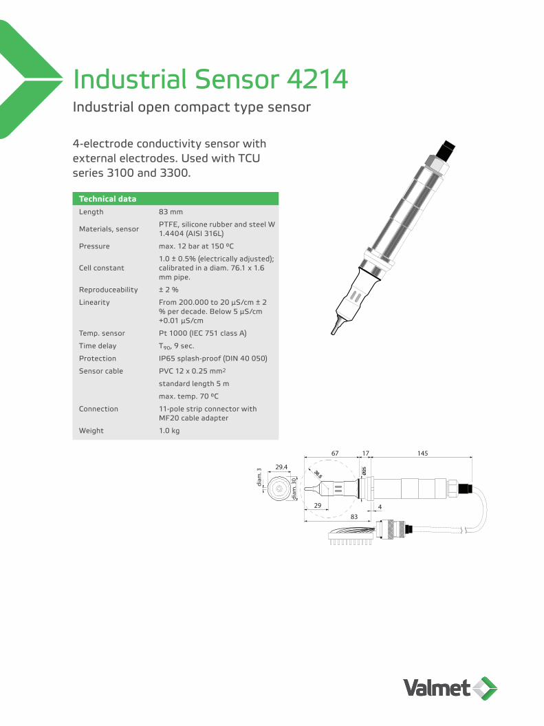
Industrial open compact type sensor
Industrial Sensor 4214
4-electrode conductivity sensor with external electrodes. Used with TCU series 3100 and 3300.
Technical dataLength 83 mm
Materials, sensor PTFE, silicone rubber and steel W 1.4404 (AISI 316L)
Pressure max. 12 bar at 150 °C
Cell constant1.0 ± 0.5% (electrically adjusted); calibrated in a diam. 76.1 x 1.6 mm pipe.
Reproduceability ± 2 %
Linearity From 200.000 to 20 μS/cm ± 2 % per decade. Below 5 μS/cm +0.01 μS/cm
Temp. sensor Pt 1000 (IEC 751 class A)
Time delay T90, 9 sec.
Protection IP65 splash-proof (DIN 40 050)
Sensor cable PVC 12 x 0.25 mm2
standard length 5 m
max. temp. 70 °C
Connection 11-pole strip connector with MF20 cable adapter
Weight 1.0 kg

For more information, contact your local Valmet office. www.valmet.com Specifications in this document are subject to change without notice. Product names in this publication are all trademarks of Valmet Corporation.©
Val
met
Cor
pora
tion,
D07
439
V1.
0 EN
04/
2015
SMSslip-on�ange
D 8464-28464-1
Type8265826682678267
SMS51
63.576.1
101.6
D658093
127
Type84648465846684678468
DN4051657580
D56
68.586
93.7100.0
DIN 11851
D Plastic pipesD63: Meas. error approx. -5%D75: Meas. error approx. -3%D90: Ref. diameter (0%)
DIN 11851, DN40
8464
36.5
8903
8911
ID Steel pipesID49: Meas. error approx. +9%ID66: Meas. error approx. +3%ID73: Ref. diameter (0%)
75
88038901
8901
60
8901
8935
diam. 84
Guidepin
8931
8930
8903
8921
8903
Use threadgasket
Tube must beplaced onchamferedinside.
Packing onTOP SIDE ofunion nut!
Accessories
Slip-on flanges types 826x, 846x
Typical mounting
For more information, contact your local Valmet office. www.valmet.com Specifications in this document are subject to change without notice. Product names in this publication are all trademarks of Valmet Corporation.©
Val
met
Cor
pora
tion,
D07
440
V1.
0 EN
04/
2015
67 17 145
4
29.4
29
83
diam
. 3
diam
. 30
8904
89778980
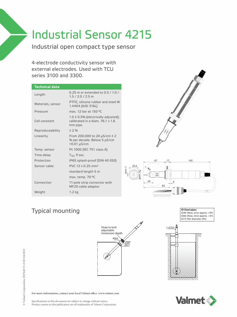
Strap to lockadjustableimmersion depth
ID Steel pipesID49: Meas. error approx. +9%ID66: Meas. error approx. +3%ID73: Ref. diameter (0%)
L=0.5m
Industrial open compact type sensor
Industrial Sensor 4215
4-electrode conductivity sensor with external electrodes. Used with TCU series 3100 and 3300.
Technical data
Length 0.25 m or extended to 0.5 / 1.0 / 1.5 / 2.0 / 2.5 m
Materials, sensor PTFE, silicone rubber and steel W 1.4404 (AISI 316L)
Pressure max. 12 bar at 150 °C
Cell constant1.0 ± 0.5% (electrically adjusted); calibrated in a diam. 76.1 x 1.6 mm pipe.
Reproduceability ± 2 %
Linearity From 200.000 to 20 μS/cm ± 2 % per decade. Below 5 μS/cm +0.01 μS/cm
Temp. sensor Pt 1000 (IEC 751 class A)
Time delay T90, 9 sec.
Protection IP65 splash-proof (DIN 40 050)
Sensor cable PVC 12 x 0.25 mm2
standard length 5 m
max. temp. 70 °C
Connection 11-pole strip connector with MF20 cable adapter
Weight 1.2 kg
Typical mounting
For more information, contact your local Valmet office. www.valmet.com Specifications in this document are subject to change without notice. Product names in this publication are all trademarks of Valmet Corporation.©
Val
met
Cor
pora
tion,
D07
710
V1.
0 EN
04/
2015
149
302
67
4618
103
NV41
NV55
BSP 1.5”NPT 1.5”
R=37
ø29
ø48
max. 7548115
180
BSP 1 ½”Dismount outer joint of
ball valve before welding.
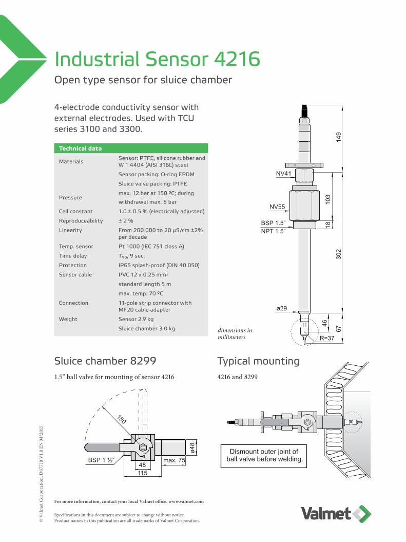
Open type sensor for sluice chamber
Industrial Sensor 4216
4-electrode conductivity sensor with external electrodes. Used with TCU series 3100 and 3300.
Technical data
Materials Sensor: PTFE, silicone rubber and W 1.4404 (AISI 316L) steel
Sensor packing: O-ring EPDM
Sluice valve packing: PTFE
Pressuremax. 12 bar at 150 °C; during
withdrawal max. 5 bar
Cell constant 1.0 ± 0.5 % (electrically adjusted)
Reproduceability ± 2 %
Linearity From 200 000 to 20 μS/cm ±2% per decade
Temp. sensor Pt 1000 (IEC 751 class A)
Time delay T90, 9 sec.
Protection IP65 splash-proof (DIN 40 050)
Sensor cable PVC 12 x 0.25 mm2
standard length 5 m
max. temp. 70 °C
Connection 11-pole strip connector with MF20 cable adapter
Weight Sensor 2.9 kg
Sluice chamber 3.0 kg
Sluice chamber 8299 Typical mounting1.5” ball valve for mounting of sensor 4216 4216 and 8299
dimensions in millimeters

L=12529.4
Ø3
Ø30 Ø25
136
75
Ø25
Standard 11-pole stripdimensions in millimeters
Durable industrial sensor
Industrial Sensor 4221
4-electrode conductivity sensor with internal electrodes. Used with TCU series 3100 and 3300.
Technical dataLength 125 mm
Materials PTFE and steel W 1.4404 (AISI 316L)
Pressure 25 bar at 210 °C
Cell constant 1.0 ± 0.5% (electrically adjusted)
Reproduceability ± 1.5%, min. ± 8 nS/cm
Linearity 2000 000 to 0.2 μS/cm ±1% per decade + 8 nS/cm
Temp. sensor Pt 1000 (IEC 751 class A)
Time delay T90, 20 sec.
Protection IP65 splash-proof (DIN 40 050)
Sensor cable PVC 12 x 0.25 mm2 screened
standard length 3 m, 5 m ~ 1 μS/cm, 15 m ~ 5 μS/cm
max. temp. 70 °C
Connection 11-pole strip connector with MF20 cable adapter
Weight 0.7 kg

For more information, contact your local Valmet office. www.valmet.com Specifications in this document are subject to change without notice. Product names in this publication are all trademarks of Valmet Corporation.©
Val
met
Cor
pora
tion,
D07
552
V1.
0 EN
04/
2015
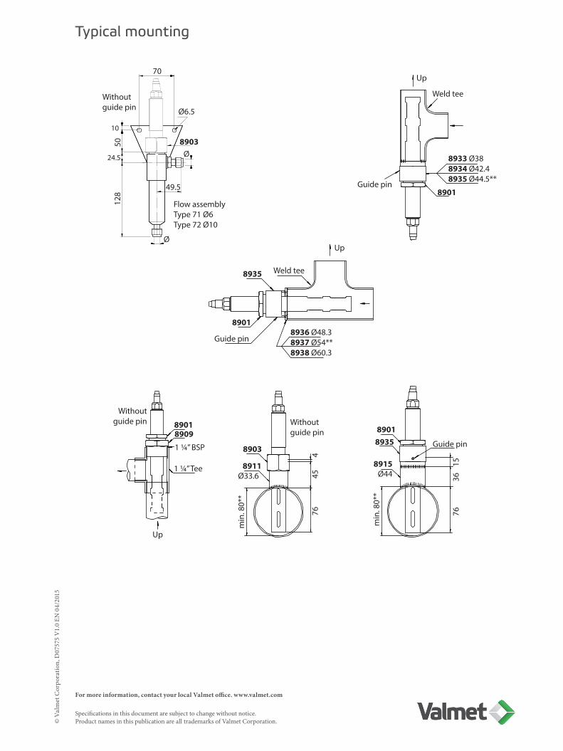
Typical mounting
70
Withoutguide pin Ø6.5
Flow assemblyType 71 Ø6Type 72 Ø10
1050
24.5
128
8903Ø
Ø
49.5
Up
Weld tee
8933 Ø388934 Ø42.48935 Ø44.5**
Guide pin8901
Up
Weld tee8935
8901
Guide pin8936 Ø48.38937 Ø54**8938 Ø60.3
Withoutguide pin 8901
8909
Up
1 ¼” BSP
1 ¼” Tee
8903
8911Ø33.6
Withoutguide pin
min
. 80*
*
7645
4
min
. 80*
*
7636
15Guide pin
89018935
8915Ø44
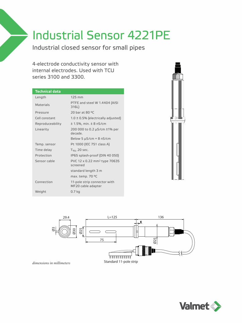
L=12529.4
Ø3
Ø30 Ø25
136
75
Ø25
Standard 11-pole stripdimensions in millimeters
Industrial closed sensor for small pipes
Industrial Sensor 4221PE
4-electrode conductivity sensor with internal electrodes. Used with TCU series 3100 and 3300.
Technical dataLength 125 mm
Materials PTFE and steel W 1.4404 (AISI 316L)
Pressure 20 bar at 80 °C
Cell constant 1.0 ± 0.5% (electrically adjusted)
Reproduceability ± 1.5%, min. ± 8 nS/cm
Linearity 200 000 to 0.2 μS/cm ±1% per decade.
Below 5 μS/cm + 8 nS/cm
Temp. sensor Pt 1000 (IEC 751 class A)
Time delay T90, 20 sec.
Protection IP65 splash-proof (DIN 40 050)
Sensor cable PVC 12 x 0.22 mm2 type 70635 screened
standard length 3 m
max. temp. 70 °C
Connection 11-pole strip connector with MF20 cable adapter
Weight 0.7 kg
For more information, contact your local Valmet office. www.valmet.com Specifications in this document are subject to change without notice. Product names in this publication are all trademarks of Valmet Corporation.©
Val
met
Cor
pora
tion,
D07
575
V1.
0 EN
04/
2015
Typical mounting
70
Withoutguide pin Ø6.5
Flow assemblyType 71 Ø6Type 72 Ø10
1050
24.5
128
8903Ø
Ø
49.5
Up
Weld tee
8933 Ø388934 Ø42.48935 Ø44.5**
Guide pin8901
Up
Weld tee8935
8901
Guide pin8936 Ø48.38937 Ø54**8938 Ø60.3
Withoutguide pin 8901
8909
Up
1 ¼” BSP
1 ¼” Tee
8903
8911Ø33.6
Withoutguide pin
min
. 80*
*
7645
4
min
. 80*
*
7636
15Guide pin
89018935
8915Ø44
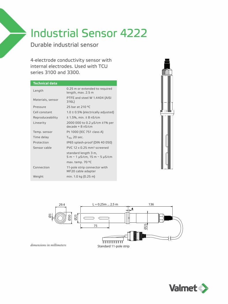
L = 0.25m ... 2.5 m 29.4
Ø3
Ø30 Ø25
136
75
Ø25
Standard 11-pole stripdimensions in millimeters
Durable industrial sensor
Industrial Sensor 4222
4-electrode conductivity sensor with internal electrodes. Used with TCU series 3100 and 3300.
Technical data
Length 0.25 m or extended to required length, max. 2.5 m
Materials, sensor PTFE and steel W 1.4404 (AISI 316L)
Pressure 25 bar at 210 °C
Cell constant 1.0 ± 0.5% (electrically adjusted)
Reproduceability ± 1.5%, min. ± 8 nS/cm
Linearity 2000 000 to 0.2 μS/cm ±1% per decade + 8 nS/cm
Temp. sensor Pt 1000 (IEC 751 class A)
Time delay T90, 20 sec.
Protection IP65 splash-proof (DIN 40 050)
Sensor cable PVC 12 x 0.25 mm2 screened
standard length 3 m, 5 m ~ 1 μS/cm, 15 m ~ 5 μS/cm
max. temp. 70 °C
Connection 11-pole strip connector with MF20 cable adapter
Weight min. 1.0 kg (0.25 m)
For more information, contact your local Valmet office. www.valmet.com Specifications in this document are subject to change without notice. Product names in this publication are all trademarks of Valmet Corporation.©
Val
met
Cor
pora
tion,
D07
560
V1.
0 EN
04/
2015
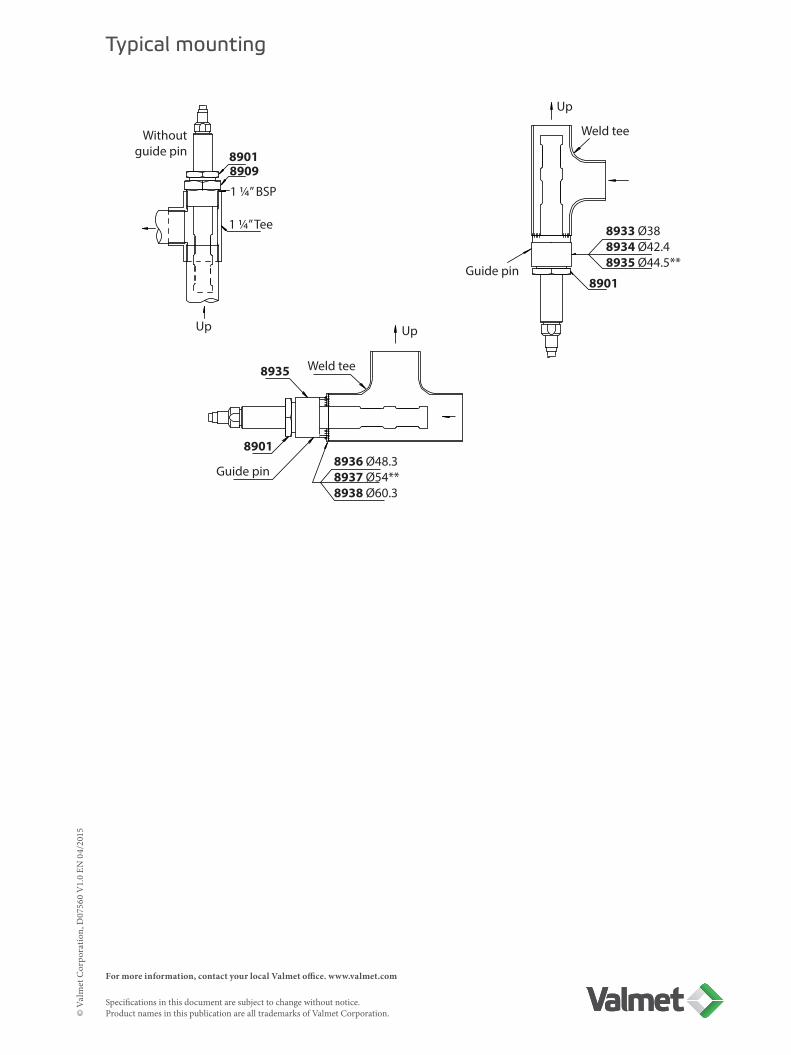
Typical mounting
Up
Weld tee
8933 Ø388934 Ø42.48935 Ø44.5**
Guide pin8901
Up
Weld tee8935
8901
Guide pin8936 Ø48.38937 Ø54**8938 Ø60.3
Withoutguide pin 8901
8909
Up
1 ¼” BSP
1 ¼” Tee
Durable industrial sensor for sluice chamber
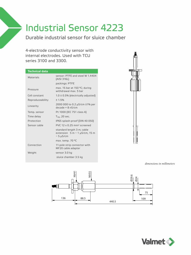
Industrial Sensor 4223
4-electrode conductivity sensor with internal electrodes. Used with TCU series 3100 and 3300.
Technical data
Materials sensor: PTFE and steel W 1.4404 (AISI 316L)
packings: PTFE
Pressure max. 15 bar at 150 °C; during withdrawal max. 5 bar
Cell constant 1.0 ± 0.5% (electrically adjusted)
Reproduceability ± 1.5%
Linearity 2000 000 to 0.2 μS/cm ±1% per decade + 8 nS/cm
Temp. sensor Pt 1000 (IEC 751 class A)
Time delay T90, 20 sec.
Protection IP65 splash-proof (DIN 40 050)
Sensor cable PVC 12 x 0.25 mm2 screened
standard length 3 m; cable extension 5 m ~ 1 μS/cm, 15 m ~ 5 μS/cm
max. temp. 70 °C
Connection 11-pole strip connector with MF20 cable adapter
Weight sensor 3.0 kg
sluice chamber 3.5 kg
136 88.5440.5
109
75
NV4
1
NV5
5
Ø29
.6
Ø24
dimensions in millimeters

For more information, contact your local Valmet office. www.valmet.com Specifications in this document are subject to change without notice. Product names in this publication are all trademarks of Valmet Corporation.©
Val
met
Cor
pora
tion,
D07
576
V1.
0 EN
04/
2015
8834
8940
75
4
min. 84 Ø1048837
7550 75
50
D8939 for D=848940 for D=88.98941 for D=105
240
Ø48
115
180
26
115
50 75
1½ “
BSP
1 ½“
0 for D=448937 for D=548938 for D=60.3
Typical mounting- Dismount the outer joint of ball valve before welding!
269 sluice valve chamberwith 1.5” ball valve 170.29 weld connection

29.4
47 71
4
4
136
L=195
diam
.25
min. 73
diam
.3
diam
.30
Durable industrial sensor
Industrial Sensor 4224
4-electrode conductivity sensor with external electrodes. Used with TCU series 3100 and 3300.
Technical dataLength 195 mm
Materials Sensor of PTFE and steel W 1.4404 (AISI 316L)
Pressure 25 bar at 210 °C
Cell constant 1.0 ± 0.5% (electrically adjusted)
Reproduceability ± 1.5%
Linearity 2 000 000 to 20 μS/cm ±1% per decade
Temp. sensor Pt 1000 (IEC 751 class A)
Time delay T90, 25 sec.
Protection IP65 splash-proof (DIN 40 050)
Sensor cable PVC 12 x 0.25 mm2 screened
standard length 5 m
max. temp. 70 °C
Connection 11-pole strip connector with MF20 cable adapter
Weight 1.1 kg
dimensions in millimeters
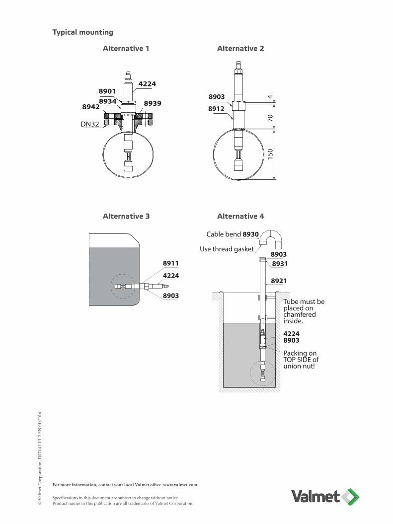
For more information, contact your local Valmet office. www.valmet.com Specifications in this document are subject to change without notice. Product names in this publication are all trademarks of Valmet Corporation.©
Val
met
Cor
pora
tion,
D07
441
V1.
2 EN
01/
2016
4224
8939
89018934
8942
DN32
8903
8912
470
150
8911
8903
4224
Cable bend 8930
Use thread gasket89038931
8921
Tube must beplaced onchamferedinside.
42248903
Packing onTOP SIDE ofunion nut!
Typical mounting
Alternative 1 Alternative 2
Alternative 3 Alternative 4

115
180
358
ø48
8919
Type 270
Type 270
Type 270
136 88.5572
134
ø24
ø29.
6
NV
41
NV
55
45min.75
Durable industrial sensor for sluice chamber
Industrial Sensor 4226
4-electrode conductivity sensor with external electrodes. Used with TCU series 3100 and 3300.
Technical data
Materials Sensor: PTFE and steel W 1.4404 (AISI 316L)
Sensor & sluice valve packings: PTFE
PressureMax. 15 bar at 150 °C.
During withdrawal max. 5 bar
Cell constant 1.0 ± 0.5% (electrically adjusted)
Reproduceability ± 1.5%
Linearity 2000 000 to 20 μS/cm ±2% per decade
Temp. sensor Pt 1000 (IEC 751 class A)
Time delay T90, 25 sec.
Protection IP65 splash-proof (DIN 40 050)
Sensor cable PVC 12 x 0.25 mm2 screened
standard length 5 m
max. temp. 70 °C
Connection 11-pole strip connector with MF20 cable adapter
Weight Sensor 3.0 kg
Sluice chamber 3.5 kg
Max. pressure / temperature
- at 15 bar 150 °C
- at 5 bar 200 °C
- at 216 lb 300 °F
- at 70 lb 390 °F
dimensions in millimeters
270 sluice chamber with 1.5” ball valve
Typical installation

For more information, contact your local Valmet office. www.valmet.com Specifications in this document are subject to change without notice. Product names in this publication are all trademarks of Valmet Corporation.©
Val
met
Cor
pora
tion,
D07
725
V1.
0 EN
04/
2015
180
115240
ø48
195
Type 269
34
b
D
d1
L2
d2
d4K
390 243.5
L2 min. 75 45
269 sluice valve with 1.5” ball valve Flanged sluice chambers
Typical installation
Max. pressure during withdrawal 5 bar
Non-standard item
dimensions in millimeters
Sluice chamber L2 D b k d1 d2 d4Type 271 DIN DN40, PN 40 79 150 18 110 44.5 18 88
Type 272 ANSI 1.5”, 300 lb 102.3 155.6 20.6 114.3 48.3 22.2 73
Type 273 DIN DN50, PN40 79 165 18 125 57 18 102
Type 274 ANSI 2”, 150 lb 102.5 152.4 19.1 102.6 60.5 19.1 91.9

29.4
44 28 144
35
72
23 4
ø3
ø25
ø30
Closed compact type sensor for small pipes
Industrial Sensor 4241
4-electrode conductivity sensor with internal electrodes. Used with TCU series 3100 and 3300.
MountingFlow opening must be parallel to the flow direction. An arrow on sensoe indicates the position of the temperature sensor.
Technical data
Materials, sensor PVDF, EPDM, silicone rubber and steel W 1.4404 (AISI 316L).
Flange & cable con-nection Steel W 1.4404 (AISI 316L)
Temperature sensor Coated with PFA
Pressure10 bar at 130 °C
(150 °C < 1 h)
Cell constant 1.0 ± 0.5% (electrically adjusted)
Reproduceability ± 2 %
Linearity 200 000 to 1 μS/cm ±2% per decade
Below 5 μS/cm +0.01 μS/cm
Temp. sensor Pt 1000 (IEC 751 class A)
Time delay T90, 9 sec.
Protection IP65 splash-proof (DIN 40 050)
Sensor cable PVC 12 x 0.25 mm2 screened
Standard length 5 m.
Sensor can optionally be mount-ed with 3 or 15 m of cable.
Measuring below 0.2 μS/cm with 3 m of cable is not recom-mended.
Do not measure below 5 μS/cm with 15 m of cable.
max. temp. 70 °C
Connection 11-pole strip connector with MF20 cable adapter
Weight 1.0 kg
dimensions in millimeters
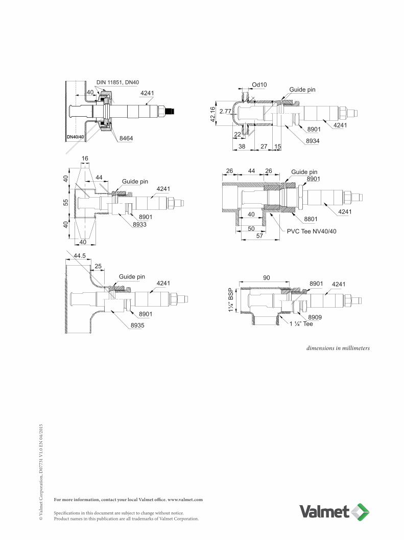
For more information, contact your local Valmet office. www.valmet.com Specifications in this document are subject to change without notice. Product names in this publication are all trademarks of Valmet Corporation.©
Val
met
Cor
pora
tion,
D07
731
V1.
0 EN
04/
2015
dimensions in millimeters
DIN 11851, DN40
4241
8464 22
38 27 15
Od10Guide pin
8901
8934
4241
42.1
6 2.77
Guide pin8901
4241
40
26 44 26
40
5057
8801
PVC Tee NV40/40
Guide pin4241
89018933
44
16
40
40
55
40
Guide pin4241
8901
8935
44.5
25
8901 4241
8909
90
1 ¼” Tee
1¼” B
SP

EN FR FI ES SV PT DE IT NL PL RU
EU
DECLARATION OF CONFORMITY VAATIMUSTENMUKAISUUSVAKUUTUS KONFORMITETSDEKLARATION KONFORMITÄTSERKLÄRUNG CONFORMITEITSVERKLARING ДЕКЛАРАЦИЯ СООТВЕТСТВИЯ
DECLARATION DE CONFORMITE DECLARACION DE CONFORMIDAD DECLARAÇÃO DO CONFORMIDADE DICHIARAZIONE DI CONFORMITA DEKLARACJA ZGODNOŚCI
Manufacturer – Valmistaja – Fabrikant – Hersteller – Fabrikant – Производитель – Fabricant – Fabricante – Fabricante – Fabriccante – Producent
Valmet Automation Oy Kehräämöntie 3 / P.O.Box 177 87101 Kajaani, FINLAND
Device – Laite – Enheten – Gerät – Apparaat – Устройство – Artifice – Dispositivo – Dispositivo – Dispositivo – Urządzenie
Valmet Conductivity Measurements
Series 2822 Conductivity Measurements
Series 3000 Portable Conductivity Measurements
Series 3100 Conductivity Measurements
Series 3200 Dual Conductivity Measurements
Series 3300 Concentration Measurements
Series 3500 Causticizing Measurements
with corresponding sensors
This product is in conformity with the requirements of the following directives, and with standards and national legislation implementing these directives:
Tuote täyttää seuraavien säännösten asettamat vaatimukset sekä nämä voimaansaattavat kansalliset päätökset:
Denna produkt uppfyller kraven i följande direktiv och standarder samt nationell lagstiftning som inför dessa direktiv:
Dieses Produkt erfüllt die folgenden Richtlinien und Normen und die nationalen Gesetze, die die Anwendung der obigen Richtlinien durchsetzen:
Dit product is in overeenstemming met de eisen van de volgende richtlijnen en met normen en nationale wetgeving ter uitvoering van deze richtlijnen: Данное изделие соответствует требованиям следующих директив, а также стандартам и национальным законодательным актам, вводящим в действие данные директивы:
Le produit est conforme aux directives et normes suivantes, et les dispositions nationales portant mise en œuvre desdites directives:
Este producto es conforme a los requisitos de las siguientes directivas y normas y legislación nacional de aplicación de estas directivas:
Este produto obedece aos requisitos das directivas e normas abaixo mencionadas e legislação nacional que transpõe as referidas directivas para o direito interno:
Questo prodotto è conforme ai requisiti delle seguenti direttive, norme e standard e legislazione nazionale implementata sulla base di queste direttive:
Ten produkt jest zgodny z wymaganiami następujących dyrektyw oraz ze standardami i przepisami krajowymi dotyczącymi wdrożenia tych dyrektyw:
Loop-powered models: 2014/30/EU (EMC Directive) 2002/95/EC (RoHS Directive) 2012/19/EU (WEEE Directive)
Line-powered models:
2014/30/EU (EMC Directive) 2014/35/EC (Low Voltage Directive) 2002/95/EC (RoHS Directive) 2012/19/EU (WEEE Directive)
Juha Koistinen Vice President
Valmet Automation Oy Control & Measurement Systems
Signature – Allekirjoitus – Underskrift – Unterschrift – Handtekening – Подпись – Signature – Firma –
Firma – Assinatura – Podpis
Clarification of signature, position – Nimenselvennys, asema – Namnförtydligande, befattning – Unterschrift in Maschinenschrift, Position – Verduidelijking van handtekening, positie –
Расшифровка подписи, должность – Nom en toutes letters, fonction – Nombre y cargo – Nome en função do assinante – Firma in stampatello, mansione – Imię i nazwisko, stanowisko

Valmet Automation Inc.Kehräämöntie 3 / P.O.Box 177FI-87101 Kajaani, Finlandtel. +358 10 672 0000, fax +358 10 676 1981www.valmet.com
This document is the exclusive intellectual property of Valmet Corporation and/or its subsidiaries (collectively “Valmet”) and is furnished solely for operating and maintaining the supplied equipment and/or software. Use of the document for any other project or purpose is prohibited. All copyrights to the document are reserved by Valmet. Accordingly, the document or the information contained therein shall not (whether partly or entirely) be reproduced, copied or disclosed to a third party without prior written consent of Valmet.
Copyright © 09/2016 Valmet Automation Inc.


