
VOLVO V50
Owner's Manual Web Edition

Welcome to the world-wide family of Volvo owners. We trustthat you will enjoy many years of safe driving in your Volvo, anautomobile designed with your safety and comfort in mind. Weencourage you to familiarize yourself with the equipmentdescriptions and operating instructions in this manual. We alsourge you and your passengers to wear seat belts at all times inthis (or any other) vehicle. And, of course, please do not operatea vehicle if you may be affected by alcohol, medication or anyimpairment that could hinder your ability to drive.
Your Volvo is designed to meet all applicable safety and emis-sion standards. For further information please contact yourretailer, or:
In the USA: Volvo Cars of North America, LLC Customer CareCenter
P.O. Box 914
Rockleigh, New Jersey 07647-0914
1-800-458-1552
www.volvocars.us
In Canada: Volvo Cars of Canada Corp
National Customer Service
175 Gordon Baker Road
North York, Ontario M2H 2N7
1-800-663-8255
www.volvocanada.com
2008 © Volvo Car Corporation, All rights reserved.

Contents
4
0000 IntroductionGeneral information.................................. 10Volvo and the environment....................... 12Important warnings................................... 13
0101 SafetyOccupant safety........................................ 16Seat belts.................................................. 18Supplemental Restraint System............... 21Occupant Weight Sensor (OWS).............. 26Side impact protection airbags................. 29Volvo Inflatable Curtain (VIC).................... 30Whiplash Protection System..................... 31Crash mode.............................................. 33Child safety............................................... 34Child restraint systems............................. 36Infant seats............................................... 37Convertible seats...................................... 39Booster cushions...................................... 41ISOFIX lower anchors............................... 42Top tether anchors.................................... 44Child restraint registration and recalls...... 45
0202 Instruments and controlsInstrument overview.................................. 48Instrument panel....................................... 51Indicator and warning symbols................. 53Symbols – instrument panel..................... 55Information display................................... 5812-volt sockets......................................... 60Lighting panel........................................... 61Left-side steering wheel lever................... 64Trip computer........................................... 66Cruise control (option)............................... 68Right-side steering wheel lever................. 70Steering wheel adjustment, Hazard warn-ing flashers................................................ 73Parking brake............................................ 74Power windows......................................... 75Mirrors....................................................... 77Power moonroof (option).......................... 80Personal settings...................................... 82HomeLink® Wireless Control System(option)...................................................... 85
Contents
5
0303 ClimateGeneral information.................................. 90Air vents.................................................... 92Manual climate control.............................. 93Electronic Climate Control (ECC) –option........................................................ 96Air distribution........................................... 99
0404 InteriorFront seats.............................................. 102Interior lighting........................................ 105Storage compartments........................... 107Rear seat................................................. 111Cargo area.............................................. 113
0505 Locks and alarmRemote control and key blade................ 118Keyless drive (option as available).......... 123Locking and unlocking............................ 127Child safety locks.................................... 129Alarm (option).......................................... 130

Contents
6
0606 Starting and drivingGeneral information................................ 136Fuel requirements................................... 140Ignition switch......................................... 143Starting the vehicle................................. 144Starting the vehicle with keyless drive(option as available)................................ 146Manual transmission, 5-speed (certainmarkets only)........................................... 147Manual transmission, 6-speed (certainmarkets only)........................................... 148Automatic transmission (option)............. 149Shiftlock override.................................... 151All Wheel Drive (option)........................... 152Brake system.......................................... 153Stability system....................................... 155Towing.................................................... 157Jump starting.......................................... 159Towing a trailer....................................... 160Detachable trailer hitch........................... 162Transporting loads.................................. 163Blind Spot Information System (BLIS)–option...................................................... 164Park assist (Option/accessory)............... 168
0707 Wheels and tiresGeneral information................................ 174Tire inflation............................................. 176Inflation pressure—U.S. models ............ 178Inflation pressure—Canadian models .... 179Tire designations..................................... 180Glossary of tire terminology.................... 182Vehicle loading........................................ 183Uniform tire quality gradings................... 185Snow chains, snow tires, studded tires. . 186Temporary spare..................................... 187Wheel nuts.............................................. 188Tire rotation............................................. 189Changing a wheel................................... 190Tire Sealing System ............................... 192Tire Pressure Monitoring System (TPMS) 197 08
08 Car careWashing and cleaning the car................. 202Paint touch up......................................... 206
Contents
7
0909 Maintenance and servicingVolvo maintenance.................................. 210Maintaining your car............................... 212Hood....................................................... 214Engine compartment............................... 215Engine oil................................................ 216Fluids....................................................... 218Wiper blades........................................... 220Battery..................................................... 221Replacing bulbs...................................... 223Fuses....................................................... 230 10
10 AudioAudio functions....................................... 240Radio functions....................................... 244CD player/CD changer............................ 249Audio menu............................................. 253Bluetooth hands-free connection......... 254
1111 SpecificationsLabel information.................................... 262Dimensions and weights......................... 264Fuel, oils, and fluids................................ 267Engine oil................................................ 269Engine specifications.............................. 270Electrical system..................................... 272Three-way catalytic converter................. 274Volvo programs....................................... 275
Contents
8
1212 IndexIndex....................................................... 276

Contents
9

Introduction
General information
10
Shiftlock (automatic transmission)When your car is parked, the gear selector islocked in the Park (P) position. To release theselector from this position, turn the ignition keyto position II (or start the engine), depress thebrake pedal, press the button on the front sideof the gear selector and move the selector fromPark (P).
Keylock (automatic transmission)When the ignition is switched off, the gearselector must be in the Park (P) position beforethe key can be removed from the ignitionswitch.
Anti-lock Brake System (ABS)The ABS system in your car performs a self-diagnostic test when the vehicle first reachesthe speed of approximately 12 mph(20 km/h). The brake pedal will pulsate severaltimes and a sound may be audible from theABS control module. This is normal.
Fuel filler doorPress the button on the light switch panel whenthe car is at a standstill to open the fuel fillerdoor.
Fuel filler capAfter refueling, close the fuel filler cap by turn-ing it clockwise until it clicks into place. If thiscap is not closed tightly or if the engine is run-ning when the car is refueled, the Malfunction
Indicator Lamp ("Check Engine" light) mayindicate a fault.
About this manual• Before you operate your vehicle for the first
time, please familiarize yourself with thenew-engine oil consumption information,see page 216. You should also be familiarwith the information found in the chapters"Instruments and controls", and "Startingand driving".
• Information contained in the balance of themanual is extremely useful and should beread after operating the vehicle for the firsttime.
• The manual is structured so that it can beused for reference. For this reason, itshould be kept in the vehicle for readyaccess.
NOTE
• Optional or accessory equipmentdescribed in this manual may not beavailable in all countries or markets.Please note that some vehicles may beequipped differently, depending onspecial legal requirements.
• All information, illustrations and specifi-cations contained in this manual arebased on the latest product informationavailable at the time of publication.
• Volvo reserves the right to make modelchanges at any time, or to change spec-ifications or design without notice andwithout incurring obligation.
• Do not export your Volvo to anothercountry before investigating that coun-try's applicable safety and emissioncontrol requirements. In some cases itmay be difficult or impossible to complywith these requirements. Modificationsto the emission control system(s) mayrender your Volvo not certifiable forlegal operation in the U.S., Canada andother countries.

Introduction
General information
11
WARNING
If your vehicle is involved in an accident,unseen damage may affect its driveabilityand safety.
WARNING
CALIFORNIA proposition 65
Engine exhaust, some of its constituents,and certain vehicle components contain oremit chemicals known to the state of Cali-fornia to cause cancer, and birth defects orother reproductive harm. In addition, certainfluids contained in vehicles and certainproducts of component wear contain oremit chemicals known to the State of Cali-fornia to cause cancer, and birth defects orother reproductive harm.

Introduction
Volvo and the environment
12
Volvo is committed to the well being of its cus-tomers. As a natural part of this commitment,we care about the environment in which we alllive. Caring for the environment means aneveryday involvement in reducing our environ-mental impact. Volvo's environmental activitiesare based on a holistic view, which means weconsider the overall environmental impact of aproduct throughout its complete life cycle. Inthis context, design, production, product use,and recycling are all important considerations.In production, Volvo has partly or completelyphased out several chemicals including CFCs,lead chromates, asbestos, and cadmium; andreduced the number of chemicals used in ourplants 50% since 1991.
Volvo was the first in the world to introduce intoproduction a three-way catalytic converter witha Lambda sond, now called the heated oxygensensor, in 1976. The current version of thishighly efficient system reduces emissions ofharmful substances (CO, HC, NOx) from theexhaust pipe by approximately 95 – 99% andthe search to eliminate the remaining emis-sions continues. Volvo is the only automobilemanufacturer to offer CFC-free retrofit kits forthe air conditioning system of all models as farback as the 1975 model 240. Advanced elec-tronic engine controls and cleaner fuels arebringing us closer to our goal. After Volvo vehi-cles and parts have fulfilled their use, recycling
is the next critical step in completing the lifecycle. The metal content is about 75% of thetotal weight of a vehicle, which makes the vehi-cle among the most recycled industrial prod-ucts. In order to have efficient and well-controlled recycling, dismantling information isavailable for all Volvo models. For Volvo, allhomogeneous plastic parts weighing morethan 3.4 oz. (100 grams) are marked with inter-national symbols that indicate how the com-ponent is to be sorted for recycling. In additionto continuous environmental refinement ofconventional gasoline-powered internal com-bustion engines, Volvo is actively looking atadvanced technology alternative-fuel vehicles.
When you drive a Volvo, you become our part-ner in the work to lessen the car's impact onthe environment. To reduce your vehicle'senvironmental impact, you can:
• Maintain proper air pressure in your tires.Tests have shown decreased fuel econ-omy with improperly inflated tires.
• Follow the recommended maintenanceschedule in your Warranty and ServiceRecords Information booklet.
• Drive at a constant speed whenever pos-sible.
• See a trained and qualified Volvo servicetechnician as soon as possible for inspec-tion if the check engine (malfunction indi-
cator) light illuminates, or stays on after thevehicle has started.
• Properly dispose of any vehicle-relatedwaste such as used motor oil, used batter-ies, brake pads, etc.
• When cleaning your vehicle, please usegenuine Volvo car care products. All Volvocar care products are formulated to beenvironmentally friendly.
For additional information regarding the envi-ronmental activities in which Volvo Cars ofNorth America, LLC and Volvo Car Corporationare involved, visit our Internet home page at:http://www.volvocars.us.
WARNING
Certain components of this vehicle such asair bag modules, seat belt pretensioners,adaptive steering columns, and button cellbatteries may contain Perchlorate material.Special handling may apply for service orvehicle end of life disposal.
See www.dtsc.ca.gov/hazardouswaste/perchlorate.

Introduction
Important warnings
13
Accessory Installation• We strongly recommend that Volvo owners
install only genuine, Volvo-approvedaccessories, and that accessory installa-tions be performed only by a trained andqualified Volvo service technician.
• Genuine Volvo accessories are tested toensure compatibility with the performance,safety, and emission systems in your vehi-cle. Additionally, a trained and qualifiedVolvo service technician knows whereaccessories may and may not be safelyinstalled in your Volvo. In all cases, pleaseconsult a trained and qualified Volvo serv-ice technician before installing any acces-sory in or on your vehicle.
• Accessories that have not been approvedby Volvo may or may not be specificallytested for compatibility with your vehicle.Additionally, an inexperienced installermay not be familiar with some of your vehi-cle's systems.
• Any of your vehicle's performance andsafety systems could be adversely affec-ted if you install accessories that Volvo hasnot tested, or if you allow accessories to beinstalled by someone unfamiliar with yourvehicle.
• Damage caused by unapproved orimproperly installed accessories may notbe covered by your new vehicle warranty.See your Warranty and Service Records
Information booklet for more warrantyinformation. Volvo assumes no responsi-bility for death, injury, or expenses thatmay result from the installation of nonge-nuine accessories.
Driver distraction• Driver distraction results from driver activ-
ities that are not directly related to control-ling the vehicle in the driving environment.Your new Volvo is, or can be, equippedwith many feature-rich entertainment andcommunication systems. These includehands-free cellular telephones, navigationsystems, and multipurpose audio systems.You may also own other portable elec-tronic devices for your own convenience.When used properly and safely, they enrichthe driving experience. Improperly used,any of these could cause a distraction.
• For all of these systems, we want to pro-vide the following warning that reflects thestrong Volvo concern for your safety:
• Never use these devices or any feature ofyour vehicle in a way that distracts youfrom the task of driving safely. Distractioncan lead to a serious accident. In additionto this general warning, we offer the fol-lowing guidance regarding specific newerfeatures that may be found in your vehicle:
• Never use a hand-held cellular telephonewhile driving. Some jurisdictions prohibit
cellular telephone use by a driver while thevehicle is moving.
• If your vehicle is equipped with a naviga-tion system, set and make changes to yourtravel itinerary only with the vehicle parked.
• Never program your audio system whilethe vehicle is moving. Program radio pre-sets with the vehicle parked, and use yourprogrammed presets to make radio usequicker and simpler.
• Never use portable computers or personaldigital assistants while the vehicle is mov-ing.
A driver has a responsibility to do everythingpossible to ensure his or her own safety andthe safety of passengers in the vehicle and oth-ers sharing the roadway. Avoiding distractionsis part of that responsibility.

G020871
14
Occupant safety...................................................................................... 16Seat belts................................................................................................ 18Supplemental Restraint System.............................................................. 21Occupant Weight Sensor (OWS)............................................................. 26Side impact protection airbags............................................................... 29Volvo Inflatable Curtain (VIC).................................................................. 30Whiplash Protection System................................................................... 31Crash mode............................................................................................. 33Child safety............................................................................................. 34Child restraint systems........................................................................... 36Infant seats.............................................................................................. 37Convertible seats.................................................................................... 39Booster cushions.................................................................................... 41ISOFIX lower anchors............................................................................. 42Top tether anchors.................................................................................. 44Child restraint registration and recalls.................................................... 45
01SAFETY

01 Safety
Occupant safety01
16
Volvo's concern for safetySafety is Volvo's cornerstone. Our concerndates back to 1927 when the first Volvo rolledoff the production line. Three-point seat belts(a Volvo invention), safety cages, and energy-absorbing impact zones were designed intoVolvo cars long before it was fashionable orrequired by government regulation.
We will not compromise our commitment tosafety. We continue to seek out new safetyfeatures and to refine those already in our cars.You can help. We would appreciate hearingyour suggestions about improving automobilesafety. We also want to know if you ever havea safety concern with your car. Call us in theU.S. at: 1-800-458-1552 or in Canada at:1-800-663-8255.
Occupant safety remindersHow safely you drive doesn't depend on howold you are but rather on:
• How well you see.
• Your ability to concentrate.
• How quickly you make decisions understress to avoid an accident.
The following suggestions are intended to helpyou cope with the ever changing trafficenvir-onment.
• Never drink and drive.
• If you are taking any medication, consultyour physician about its potential effectson your driving abilities.
• Take a driver-retraining course.
• Have your eyes checked regularly.
• Keep your windshield and headlightsclean.
• Replace wiper blades when they start toleave streaks.
• Take into account the traffic, road, andweather conditions, particularly withregard to stopping distance.
Reporting safety defects in the U.S.If you believe that your vehicle has adefect which could cause a crash orcould cause injury or death, youshould immediately inform theNational Highway Traffic SafetyAdministration (NHTSA) in addition tonotifying Volvo Cars of North Amer-ica, LLC. If NHTSA receives similarcomplaints, it may open an investiga-tion, and if it finds that a safety defectexists in a group of vehicles, it mayorder a recall and remedy campaign.
However, NHTSA cannot becomeinvolved in individual problemsbetween you, your retailer, or VolvoCars of North America, LLC.
To contact NHTSA, you may eithercall the Auto Safety Hotline toll-free at
1-888-327-4236
(TTY: 1-800-424-9153) or write to:NHTSA, U.S. Department of Trans-portation, Washington D.C. 20590.
You can also obtain other informationabout motor vehicle safety from:
http://www.safercar.govVolvo strongly recommends that if your vehicleis covered under a service campaign, safety oremission recall or similar action, it should becompleted as soon as possible. Please checkwith your local retailer or Volvo Cars of NorthAmerica, LLC if your vehicle is covered underthese conditions.
NHTSA can be reached at:
Internet:
http://www.nhtsa.gov
Telephone:

01 Safety
Occupant safety 01
17
1-888-DASH-2-DOT (1-888-327-4236).
Reporting safety defects in CanadaIf you believe your vehicle has a defect thatcould cause a crash or could cause injury ordeath, you should immediately inform Trans-port Canada in addition to notifying Volvo Carsof Canada Corp.
To contact Transport Canada, call (800)333-0510, or (613) 993-9851 if you are callingfrom the Ottawa region.
01 Safety
Seat belts01
18
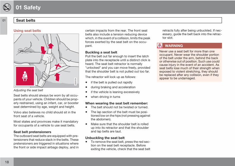
Using seat belts
G020104
Adjusting the seat belt
Seat belts should always be worn by all occu-pants of your vehicle. Children should be prop-erly restrained, using an infant, car, or boosterseat determined by age, weight and height.
Volvo also believes no child should sit in thefront seat of a vehicle.
Most states and provinces make it mandatoryfor occupants of a vehicle to use seat belts.
Seat belt pretensionersThe outboard seat belts are equipped with pre-tensioners that reduce slack in the belts. Thesepretensioners are triggered in situations wherethe front or side impact airbags deploy, and in
certain impacts from the rear. The front seatbelts also include a tension reducing devicewhich, in the event of a collision, limits the peakforces exerted by the seat belt on the occu-pant.
Buckling a seat beltPull the belt out far enough to insert the latchplate into the receptacle until a distinct click isheard. The seat belt retractor is normally"unlocked" and you can move freely, providedthat the shoulder belt is not pulled out too far.
The retractor will lock up as follows:
• if the belt is pulled out rapidly
• during braking and acceleration
• if the vehicle is leaning excessively
• when driving in turns
When wearing the seat belt remember:• The belt should not be twisted or turned.
• The lap section of the belt must be posi-tioned low on the hips (not pressing againstthe abdomen).
• Make sure that the shoulder belt is rolledup into its retractor and that the shoulderand lap belts are taut.
Unbuckling the seat belt• To remove the seat belt, press the red sec-
tion on the seat belt receptacle. Beforeexiting the vehicle, check that the seat belt
retracts fully after being unbuckled. If nec-essary, guide the belt back into the retrac-tor slot.
WARNING
Never use a seat belt for more than oneoccupant. Never wear the shoulder portionof the belt under the arm, behind the backor otherwise out of position. Such use couldcause injury in the event of an accident. Asseat belts lose much of their strength whenexposed to violent stretching, they shouldbe replaced after any collision, even if theyappear to be undamaged.

01 Safety
Seat belts 01
19
WARNING
• Never repair the belt yourself; have thiswork done by a trained and qualifiedVolvo service technician only.
• Any device used to induce slack into theshoulder belt portion of the three-pointbelt system will have a detrimentaleffect on the amount of protection avail-able to you in the event of a collision.
• The seat back should not be tilted toofar back. The shoulder belt must be tautin order to function properly.
• Do not use child safety seats or childbooster cushions/backrests in the frontpassenger's seat. We also recommendthat children who have outgrown thesedevices sit in the rear seat with the seatbelt properly fastened.
Seat belt use during pregnancy
G020105
The seat belt should always be worn duringpregnancy. But it is crucial that it be worn in thecorrect way. The diagonal section should wrapover the shoulder then be routed between thebreasts and to the side of the belly. The lapsection should lay flat over the thighs and aslow as possible under the belly. It must neverbe allowed to ride upward. Remove all slackfrom the belt and insure that it fits close to thebody without any twists.
As a pregnancy progresses, pregnant driversshould adjust their seats and steering wheelsuch that they can easily maintain control of thevehicle as they drive (which means they mustbe able to easily operate the foot pedals and
steering wheel). Within this context, theyshould strive to position the seat with as largea distance as possible between their belly andthe steering wheel.
Child seatsPlease refer to page 36 for information onsecuring child seats with the seat belts.
Seat belt reminder
G018084
Seat belt reminder light in ceiling console
The seat belt reminder consists of an audiblesignal, an indicator light near the rearview mir-ror and a symbol in the instrument panel thatalert all occupants of the vehicle if their seat

01 Safety
Seat belts01
20
belts are not fastened. These signals will lastfor approximately 6 seconds.
Rear seatsThe seat belt reminder in the rear seat has twoadditional functions:
• It provides information about which seatbelts are fastened in the rear seat. A mes-sage will appear in the information displaywhen a belt is being used or if one of therear doors has been opened. This messagewill disappear after approximately 30 sec-onds or can be erased by pressing theREAD button on the left steering wheellever.
• It also provides a reminder if one of theoccupants of the rear seat has unbuckledhis/her seat belt while the vehicle is inmotion. A visual and audible signal will begiven. These signals will stop when theseat belt has been re-buckled or can bestopped by pressing the READ button.
The message in the information display canalways be accessed, even if it has been erased,by pressing the READ button to display storedmessages.
Seat belt maintenanceCheck periodically that the seat belts are ingood condition. Use water and a mild deter-gent for cleaning. Check seat belt mechanismfunction as follows: attach the seat belt and pullrapidly on the strap.

01 Safety
Supplemental Restraint System 01
21
Supplemental Restraint System (SRS)
G026330
SRS warning light
As an enhancement to the three-point seatbelts, your Volvo is equipped with a Supple-mental Restraint System (SRS). Volvo's SRSconsists of seat belt pretensioners, front air-bags, side impact airbags, the occupantweight sensor, and inflatable curtains. All ofthese systems are monitored by the SRS con-trol module. An SRS warning light in the instru-ment panel (see the illustration) illuminateswhen the ignition key is turned to position I, II,or III, and will normally go out after approxi-mately 7 seconds if no faults are detected inthe system.
Where applicable, a text message will also bedisplayed when the SRS warning light illumi-nates. If this warning symbol is not functioningproperly, the general warning symbol
illuminates and either SRS AIRBAGSERVICE URGENT or SRS AIRBAGSERVICE REQUIRED will be displayed.
WARNING
• If the SRS warning light stays on afterthe engine has started or if it illuminateswhile you are driving, have the vehicleinspected by a trained and qualifiedVolvo service technician as soon aspossible.
• Never try to repair any component orpart of the SRS yourself. Any interfer-ence in the system could cause mal-function and serious injury. All work onthese systems should be performed bya trained and qualified Volvo servicetechnician.
WARNING
If your vehicle has been subjected to floodconditions (e.g. soaked carpeting/standingwater on the floor of the vehicle) or if yourvehicle has become flood-damaged in anyway, do not attempt to start the vehicle orput the key in the ignition before discon-necting the battery (see below). This maycause airbag deployment which could resultin personal injury. Have the vehicle towed toa trained and qualified Volvo service tech-nician for repairs.
Automatic transmission
Before attempting to tow the vehicle, usethe following procedure to override theshiftlock system to move the gear selectorto the neutral position:
1. Switch off the ignition for at least10 minutes and disconnect the battery.
2. Wait at least one minute.
3. Insert the key in the ignition and turn itto position II.
4. Press firmly on the brake pedal.
5. Move the gear selector from Park (P) tothe Neutral (N) position, see page 151,for information on manually overridingthe shiftlock system.
01 Safety
Supplemental Restraint System01
22
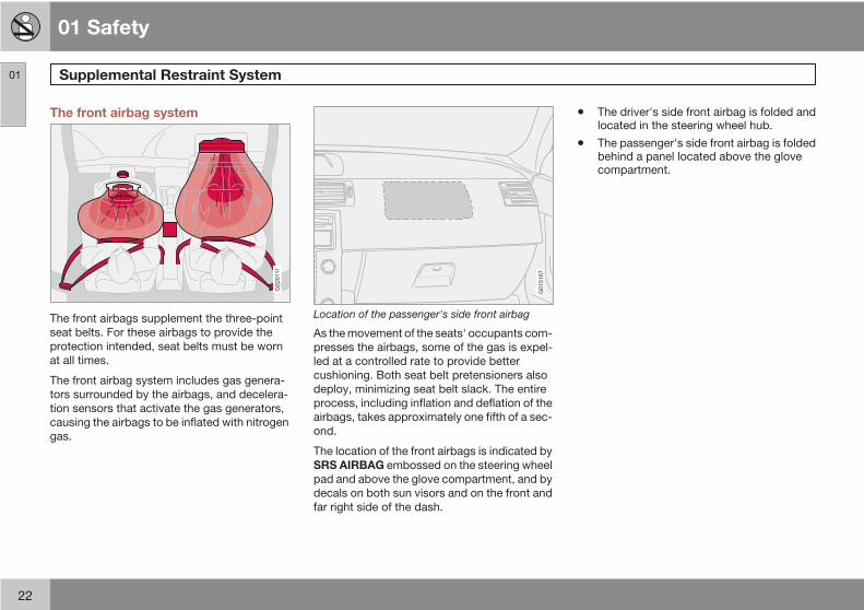
The front airbag system
G020111
The front airbags supplement the three-pointseat belts. For these airbags to provide theprotection intended, seat belts must be wornat all times.
The front airbag system includes gas genera-tors surrounded by the airbags, and decelera-tion sensors that activate the gas generators,causing the airbags to be inflated with nitrogengas.
G015167
Location of the passenger's side front airbag
As the movement of the seats' occupants com-presses the airbags, some of the gas is expel-led at a controlled rate to provide bettercushioning. Both seat belt pretensioners alsodeploy, minimizing seat belt slack. The entireprocess, including inflation and deflation of theairbags, takes approximately one fifth of a sec-ond.
The location of the front airbags is indicated bySRS AIRBAG embossed on the steering wheelpad and above the glove compartment, and bydecals on both sun visors and on the front andfar right side of the dash.
• The driver's side front airbag is folded andlocated in the steering wheel hub.
• The passenger's side front airbag is foldedbehind a panel located above the glovecompartment.
01 Safety
Supplemental Restraint System 01
23
WARNING
• The airbags in the vehicle are designedto be a SUPPLEMENT to-not a replace-ment for-the three-point seat belts. Formaximum protection, wear seat belts atall times. Be aware that no system canprevent all possible injuries that mayoccur in an accident.
• Never drive a vehicle with a steeringwheel-mounted airbag with your handson the steering wheel pad/airbag hous-ing.
• The front airbags are designed to helpprevent serious injury. Deploymentoccurs very quickly and with consider-able force. During normal deploymentand depending on variables such asseating position, one may experienceabrasions, bruises, swellings, or otherinjuries as a result from deployment ofone or both of the airbags.
• When installing any accessory equip-ment, make sure that the front airbagsystem is not damaged. Any interfer-ence in the system could cause mal-function.
Front airbag deployment• The front airbags are designed to deploy
during certain frontal or front-angular col-lisions, impacts, or decelerations, depend-ing on the crash severity, angle, speed andobject impacted. The airbags may alsodeploy in certain non-frontal collisionswhere rapid deceleration occurs.
• The SRS sensors, which trigger the frontairbags, are designed to react to both theimpact of the collision and the inertialforces generated by it, and to determine ifthe intensity of the collision is sufficient forthe seat belt pretensioners and/or airbagsto be deployed.
However, not all frontal collisions activate thefront airbags.
• If the collision involves a nonrigid object(e.g., a snow drift or bush), or a rigid, fixedobject at a low speed, the front airbags willnot necessarily deploy.
• Front airbags do not normally deploy in aside impact collision, in a collision from therear or in a rollover situation.
• The amount of damage to the bodyworkdoes not reliably indicate if the airbagsshould have deployed or not.
NOTE
• Deployment of front airbags occurs onlyone time during an accident. In a colli-sion where deployment occurs, the air-bags and seat belt pretensioners acti-vate. Some noise occurs and a smallamount of powder is released. Therelease of the powder may appear assmoke-like matter. This is a normalcharacteristic and does not indicate fire.
• Volvo's front airbags use special sen-sors that are integrated with the frontseat buckles. The point at which the air-bag deploys is determined by whetheror not the seat belt is being used, as wellas the severity of the collision.
• Collisions can occur where only one ofthe airbags deploys. If the impact is lesssevere, but severe enough to present aclear injury risk, the airbags are trig-gered at partial capacity. If the impact ismore severe, the airbags are triggeredat full capacity.
Should you have questions about any compo-nent in the SRS system, please contact atrained and qualified Volvo service technicianor Volvo Customer Support:
In the USA
Volvo Cars of North America, LLC

01 Safety
Supplemental Restraint System01
24
Customer Care Center
P.O. Box 914 Rockleigh, New Jersey07647-0914
1-800-458-1552
www.volvocars.us
In Canada
Volvo Cars of Canada Corp.
National Customer Service
175 Gordon Baker Road
North York, Ontario M2H 2N7
1-800-663-8255
www.volvocanada.com
WARNING
• Do not use child safety seats or childbooster cushions/backrests in the frontpassenger's seat. We also recommendthat occupants under 4 feet 7 inches(140 cm) in height who have outgrownthese devices sit in the rear seat with theseat belt fastened1.
• Never drive with the airbags deployed.The fact that they hang out can impairthe steering of your vehicle. Othersafety systems can also be damaged.
• The smoke and dust formed when theairbags are deployed can cause skinand eye irritation in the event of pro-longed exposure.
G032243
Airbag decal in the front passenger's door opening
1 See also the Occupant Weight Sensor information on page 26.

01 Safety
Supplemental Restraint System 01
25
G032525
Airbag decal on passenger's side dashboard
G032934
Airbag decal on the outside of both sun visors
WARNING
• Children must never be allowed in thefront passenger's seat. Volvo recom-mends that ALL occupants (adults andchildren) shorter than 4 feet 7 inches(140 cm) be seated in the back seat ofany vehicle with a passenger-side frontairbag. See page 35 for guidelines.
• Occupants in the front passenger's seatmust never sit on the edge of the seat,sit leaning toward the instrument panelor otherwise sit out of position.
• The occupant's back must be as uprightas comfort allows and be against theseat back with the seat belt properlyfastened.
• Feet must be on the floor, e.g., not onthe dash, seat or out of the window.
WARNING
• No objects or accessory equipment,e.g. dashboard covers, may be placedon, attached to, or installed near the airbag hatch (the area above the glovecompartment) or the area affected byairbag deployment.
• There should be no loose articles, e.g.coffee cups, on the floor, seat, or dash-board area.
• Never try to open the airbag cover onthe steering wheel or the passenger'sside dashboard. This should only bedone by a trained and qualified Volvoservice technician.
• Failure to follow these instructions canresult in injury to the vehicle occupants.

01 Safety
Occupant Weight Sensor (OWS)01
26
Disabling the passenger's side frontairbag
2
G018082
Occupant Weight Sensor (OWS) indicator light
Volvo recommends that ALL occupants (adultsand children) shorter than 4 feet 7 inches(140 cm) be seated in the rear seat of any vehi-cle with a passenger's side front airbag, and beproperly restrained. Children should always beseated in child restraints appropriate for theirsize and weight. See also the child safety rec-ommendations on page 34.
The Occupant Weight Sensor (OWS) isdesigned to meet the regulatory requirementsof Federal Motor Vehicle Safety Standard(FMVSS) 208 and is designed to disable (will
not inflate) the passenger's side front airbagunder certain conditions.
The OWS works with sensors that are part ofthe front passenger's seat and seat belt. Thesensors are designed to detect the presence ofa properly seated occupant and determine ifthe passenger's side front airbag should beenabled (may inflate) or disabled (will notinflate).
The OWS will disable (will not inflate) the pas-senger's side front airbag when:
• the front passenger's seat is unoccupied,or has small/medium objects in the frontseat,
• the system determines that an infant ispresent in a rear-facing infant seat that isinstalled according to the manufacturer'sinstructions,
• the system determines that a small child ispresent in a forward-facing child restraintthat is installed according to the manufac-turer's instructions,
• the system determines that a small child ispresent in a booster seat,
• a front passenger takes his/her weight offof the seat for a period of time,
• a child or a small person occupies the frontpassenger's seat.
The OWS uses a PASSENGER AIRBAG OFFindicator lamp which will illuminate and stay onto remind you that the passenger's side frontairbag is disabled. The PASSENGER AIRBAGOFF indicator lamp is located in the overheadconsole, near the base of the rearview mirror.
NOTE
When the ignition is switched on, the OWSindicator light will go on for up to 10 secondswhile the system performs a self-diagnostictest.
However, if a fault is detected in the system:
• The OWS indicator light will stay on
• The SRS warning light (see page 21) willcome on and stay on
The message PASS. AIRBAG OFF SERVICEURGENT will be displayed in the informationdisplay.

01 Safety
Occupant Weight Sensor (OWS) 01
27
WARNING
If a fault in the system is detected and indi-cated as explained on the preceding page,be aware that the passenger's side front air-bag will not deploy in the event of a collision.In this case, the SRS system and OccupantWeight Sensor should be inspected by atrained and qualified Volvo service techni-cian as soon as possible.
WARNING
• Never try to open, remove, or repair anycomponents in the OWS system. Thiscould result in system malfunction.Maintenance or repairs should only becarried out by an a trained and qualifiedVolvo service technician.
• The front passenger's seat should notbe modified in any way. This couldreduce pressure on the seat cushion,which might interfere with the OWS sys-tem's function.
The OWS is designed to disable (will not inflate)the passenger's side front airbag when a rearfacing infant seat, a forward-facing childrestraint, or a booster seat is detected. ThePASSENGER AIRBAG OFF indicator lamp willilluminate and stay on to remind you that the
passenger's side front airbag is disabled (seethe following table).
Passenger'sseat occu-pancy status
OWS indica-tor light sta-tus
Passenger'sside frontairbag sta-tus
Seat unoc-cupied
OWS indica-tor light
lights up
Passenger'sside frontairbag disa-bled
Seat occu-pied by lowweightoccupant/objectA
OWS indica-tor light
lights up
Passenger'sside frontairbag disa-bled
Seat occu-pied byheavy occu-pant/object
OWS indica-tor light
isnot lit
Passenger'sside frontairbag ena-bled
A Volvo recommends that children always be properlyrestrained in appropriate child restraints in the rear seats. Donot assume that the passenger's side front airbag is disabledunless the PASSENGER AIRBAG OFF indicator lamp is lit.Make sure the child restraint is properly installed. If there isany doubt as to the status of the passenger's side front air-bag, move the child restraint to the rear seat.
The OWS is designed to enable (may inflate)the passenger's side front airbag anytime the
system senses that a person of adult size issitting properly in the front passenger's seat.The PASSENGER AIRBAG OFF indicatorlamp will be off and remain off.
If a person of adult size is sitting in the frontpassenger's seat, but the PASSENGERAIRBAG OFF indicator lamp is on, it is possiblethat the person isn't sitting properly in the seat.If this happens:
1. Turn the vehicle off and ask the person toplace the seatback in an upright position.
2. Have the person sit upright in the seat,centered on the seat cushion, with the per-son's legs comfortably extended.
3. Restart the vehicle and have the personremain in this position for about twominutes. This will allow the system todetect that person and enable the pas-senger's frontal airbag.
4. If the PASSENGER AIRBAG OFF indicatorlamp remains on even after this, the personshould be advised to ride in the rear seat.
This condition reflects limitations of the OWSclassification capability. It does not indicateOWS malfunction.
ModificationsIf you are considering modifying your vehicle inany way to accommodate a disability, for
01 Safety
Occupant Weight Sensor (OWS)01
28
example by altering or adapting the driver's orfront passenger's seat(s) and/or airbag sys-tems, please contact Volvo at:
In the USA
Volvo Cars of North America, LLC
Customer Care Center
P.O. Box 914 Rockleigh, New Jersey07647-0914
1-800-458-1552
In Canada
Volvo Cars of Canada Corp.
National Customer Service
175 Gordon Baker Road North York, OntarioM2H 2N7
1-800-663-8255
WARNING
• No objects that add to the total weighton the seat should be placed on thefront passenger's seat. If a child isseated in the front passenger's seatwith any additional weight, this extraweight could cause the OWS system toenable the airbag, which might cause itto deploy in the event of a collision,thereby injuring the child.
• The seat belt should never be wrappedaround an object on the front passeng-er's seat. This could interfere with theOWS system's function.
• The front passenger's seat belt shouldnever be used in a way that exerts morepressure on the passenger than normal.This could increase the pressure exer-ted on the weight sensor by a child, andcould result in the airbag being enabled,which might cause it to deploy in theevent of a collision, thereby injuring thechild.
WARNING
Keep the following points in mind withrespect to the OWS system. Failure to followthese instructions could adversely affect thesystem's function and result in serious injuryto the occupant of the front passenger'sseat:
• The full weight of the front seat passen-ger should always be on the seat cush-ion. The passenger should never lifthim/herself off the seat cushion usingthe armrest in the door or the centerconsole, by pressing the feet on thefloor, by sitting on the edge of the seatcushion, or by pressing against thebackrest in a way that reduces pressureon the seat cushion. This could causeOWS to disable the passenger's sidefront airbag.
• Do not place any type of object on thefront passenger's seat in such a waythat jamming, pressing, or squeezingoccurs between the object and the frontseat, other than as a direct result of thecorrect use of the Automatic LockingRetractor/Emergency Locking Retrac-tor (ALR/ELR) seat belt, see page 35.
• No objects should be placed under thefront passenger's seat. This could inter-fere with the OWS system's function.
01 Safety
Side impact protection airbags 01
29
Side impact airbags – front seats only
G020118
Location of the side impact (SIPS) airbag
As an enhancement to the structural sideimpact protection built into your car, the car isalso equipped with Side Impact ProtectionSystem (SIPS) airbags.
The SIPS airbag system is designed to helpincrease occupant protection in the event ofcertain side impact collisions. The SIPS air-bags are designed to deploy only during cer-tain side-impact collisions, depending on thecrash severity, angle, speed and point ofimpact.
G025315
SIPS airbag deployment
NOTE
SIPS airbag deployment (one airbag) occursonly on the side of the vehicle affected bythe impact. The airbags are not designed todeploy in all side impact situations.
Components in the SIPS airbag systemThis SIPS airbag system consists of gas gen-erators and side airbag modules built into theoutboard sides of both front seat backrests.
WARNING
• The SIPS airbag system is a supple-ment to the structural Side Impact Pro-tection System and the three-point seatbelt system. It is not designed to deployduring collisions from the front or rear ofthe car or in rollover situations.
• The use of seat covers on the front seatsmay impede SIPS airbag deployment.
• No objects, accessory equipment orstickers may be placed on, attached toor installed near the SIPS airbag systemor in the area affected by SIPS airbagdeployment.
• Never try to open or repair any compo-nents of the SIPS airbag system. Thisshould be done only by a trained andqualified Volvo service technician.
• In order for the SIPS airbag to provideits best protection, both front seatoccupants should sit in an upright posi-tion with the seat belt properly fastened.
• Failure to follow these instructions canresult in injury to the occupants of thevehicle in the event of an accident.

01 Safety
Volvo Inflatable Curtain (VIC)01
30
The Volvo Inflatable Curtain system
G019985
This system consists of inflatable curtainslocated along the sides of the roof liners,stretching from the center of both front sidewindows to the rear edge of the rear side doorwindows. It is designed to help protect theheads of the occupants of the front seats andthe occupant of the outboard rear seating posi-tions in certain side impact collisions.
In certain side impacts, both the Inflatable Cur-tain (VIC) and the Side Impact Airbag System(SIPS airbag) will deploy. The VIC and the SIPSairbag deploy simultaneously.
NOTE
If the inflatable curtain deploys, it remainsinflated for approximately 3 seconds.
WARNING
• The VIC system is a supplement to theSide Impact Protection System. It is notdesigned to deploy during collisionsfrom the front or rear of the car or in roll-over situations.
• Never try to open or repair any compo-nents of the VIC system. This should bedone only by a trained and qualifiedVolvo service technician.
• Never hang heavy items from the ceilinghandles. This could impede deploymentof the Inflatable curtain.
WARNING
In order for the VIC to provide its best pro-tection, both front seat occupants and bothoutboard rear seat occupants should sit inan upright position with the seat belt prop-erly fastened; adults using the seat belt andchildren using the proper child restraint sys-tem. Only adults should sit in the front seats.Children must never be allowed in the frontpassenger's seat, see page 35 for guide-lines. Failure to follow these instructions canresult in injury to the vehicle occupants in anaccident.
01 Safety
Whiplash Protection System 01
31
Whiplash Protection System (WHIPS) – front seats only
G020347
The WHIPS system consists of speciallydesigned hinges and brackets on the front seatbackrests designed to help absorb some of theenergy generated in a collision from the rear(when the vehicle is "rearended").
In the event of a collision of this type, the hingesand brackets of the front seat backrests aredesigned to change position slightly to allowthe backrest/head restraint to help support theoccupant's head before moving slightly rear-ward. This movement helps absorb some ofthe forces that could result in whiplash.
WARNING
• The WHIPS system is designed to sup-plement the other safety systems inyour car. For this system to functionproperly, the three-point seat belt mustbe worn. Please be aware that no sys-tem can prevent all possible injuries thatmay occur in an accident.
• The WHIPS system is designed to func-tion in certain collisions from the rear,depending on the crash severity, angleand speed.
WARNING
• Occupants in the front seats must neversit out of position. The occupant's backmust be as upright as comfort allowsand be against the seat back with theseat belt properly fastened.
• If your car has been involved in a rear-end collision, the front seat backrestsmust be inspected by a trained andqualified Volvo service technician, evenif the seats appear to be undamaged.

01 Safety
Whiplash Protection System01
32
Certain components in the WHIPS sys-tem may need to be replaced.
• Do not attempt to service any compo-nent in the WHIPS system yourself.
G020126
WARNING
Any contact between the front seat backr-ests and the folded rear seat could impedethe function of the WHIPS system. If the rearseat is folded down, the occupied frontseats must be adjusted forward so that theydo not touch the folded rear seat.
G020125
WARNING
• Boxes, suitcases, etc. wedged behindthe front seats could impede the func-tion of the WHIPS system.
• If the rear seat backrests are foldeddown, cargo must be secured to pre-vent it from sliding forward against thefront seat backrests in the event of acollision from the rear. This could inter-fere with the action of the WHIPS sys-tem.
01 Safety
Crash mode 01
33
Driving after a collision
G026363
If the vehicle has been involved in a collision,the text CRASH MODE SEE MANUAL mayappear in the information display. This indi-cates that the vehicle's functionality has beenreduced.
This text can only be shown if the display isundamaged and the vehicle's electrical systemis intact.
CRASH MODE is a feature that is triggered ifone or more of the safety systems (for example,front or side airbags, an inflatable curtain, orone or more of the seat belt pretensioners) hasdeployed. The collision may have damaged animportant function in the vehicle, such as the
fuel lines, sensors for one of the safety sys-tems, the brake system, etc.
WARNING
• Never attempt to repair the vehicleyourself or to reset the electrical systemafter the vehicle has displayed CRASHMODE SEE MANUAL. This couldresult in injury or improper system func-tion.
• Restoring the vehicle to normal operat-ing mode should only be done by atrained and qualified Volvo service tech-nician.
• After CRASH MODE SEE MANUALhas been displayed, if you detect theodor of fuel vapor, or see any signs offuel leakage, do not attempt to start thevehicle. Leave the vehicle immediately.
Attempting to start the vehicleIf damage to the vehicle is minor and there isno fuel leakage, you may attempt to start thevehicle. To do so:
1. Remove the ignition key or optional keylessdrive start control, see page 146.
2. Reinsert the key or start control in the igni-tion switch. The vehicle will then attempt toreset CRASH MODE to normal mode.
3. Try to start the vehicle.
Moving the vehicleIf the electrical system is able to reset systemstatus to normal (CRASH MODE SEEMANUAL will no longer be displayed), thevehicle may be moved carefully from its pres-ent position, if for example, it is blocking traffic.It should, however, not be moved farther thanis absolutely necessary.
WARNING
Even if the vehicle appears to be drivableafter CRASH MODE has been set, it shouldnot be driven or towed (pulled by anothervehicle). There may be concealed damagethat could make it difficult or impossible tocontrol. The vehicle should be transportedon a flatbed tow truck to a trained and quali-fied Volvo service technician for inspection/repairs.
01 Safety
Child safety01
34
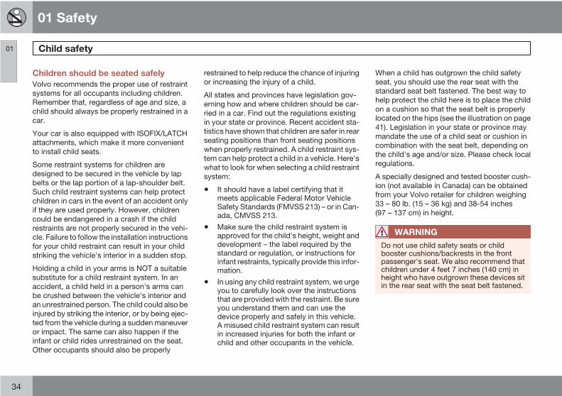
Children should be seated safelyVolvo recommends the proper use of restraintsystems for all occupants including children.Remember that, regardless of age and size, achild should always be properly restrained in acar.
Your car is also equipped with ISOFIX/LATCHattachments, which make it more convenientto install child seats.
Some restraint systems for children aredesigned to be secured in the vehicle by lapbelts or the lap portion of a lap-shoulder belt.Such child restraint systems can help protectchildren in cars in the event of an accident onlyif they are used properly. However, childrencould be endangered in a crash if the childrestraints are not properly secured in the vehi-cle. Failure to follow the installation instructionsfor your child restraint can result in your childstriking the vehicle's interior in a sudden stop.
Holding a child in your arms is NOT a suitablesubstitute for a child restraint system. In anaccident, a child held in a person's arms canbe crushed between the vehicle's interior andan unrestrained person. The child could also beinjured by striking the interior, or by being ejec-ted from the vehicle during a sudden maneuveror impact. The same can also happen if theinfant or child rides unrestrained on the seat.Other occupants should also be properly
restrained to help reduce the chance of injuringor increasing the injury of a child.
All states and provinces have legislation gov-erning how and where children should be car-ried in a car. Find out the regulations existingin your state or province. Recent accident sta-tistics have shown that children are safer in rearseating positions than front seating positionswhen properly restrained. A child restraint sys-tem can help protect a child in a vehicle. Here'swhat to look for when selecting a child restraintsystem:
• It should have a label certifying that itmeets applicable Federal Motor VehicleSafety Standards (FMVSS 213) – or in Can-ada, CMVSS 213.
• Make sure the child restraint system isapproved for the child's height, weight anddevelopment – the label required by thestandard or regulation, or instructions forinfant restraints, typically provide this infor-mation.
• In using any child restraint system, we urgeyou to carefully look over the instructionsthat are provided with the restraint. Be sureyou understand them and can use thedevice properly and safely in this vehicle.A misused child restraint system can resultin increased injuries for both the infant orchild and other occupants in the vehicle.
When a child has outgrown the child safetyseat, you should use the rear seat with thestandard seat belt fastened. The best way tohelp protect the child here is to place the childon a cushion so that the seat belt is properlylocated on the hips (see the illustration on page41). Legislation in your state or province maymandate the use of a child seat or cushion incombination with the seat belt, depending onthe child's age and/or size. Please check localregulations.
A specially designed and tested booster cush-ion (not available in Canada) can be obtainedfrom your Volvo retailer for children weighing33 – 80 lb. (15 – 36 kg) and 38-54 inches(97 – 137 cm) in height.
WARNING
Do not use child safety seats or childbooster cushions/backrests in the frontpassenger's seat. We also recommend thatchildren under 4 feet 7 inches (140 cm) inheight who have outgrown these devices sitin the rear seat with the seat belt fastened.

01 Safety
Child safety 01
35
Automatic Locking Retractor/Emergency Locking Retractor (ALR/ELR)To make child seat installation easier, eachseat belt (except for the driver's belt) is equip-ped with a locking mechanism to help keep theseat belt taut.
When attaching the seat belt to a childseat:1. Attach the seat belt to the child seat
according to the child seat manufacturer'sinstructions.
2. Pull the seat belt out as far as possible.
3. Insert the seat belt latch plate into thebuckle (lock) in the usual way.
4. Release the seat belt and pull it taut aroundthe child seat.
A sound from the seat belt retractor will beaudible at this time and is normal. The belt willnow be locked in place. This function is auto-matically disabled when the seat belt isunlocked and the belt is fully retracted.
WARNING
Do not use child safety seats or childbooster cushions/backrests in the frontpassenger's seat. We also recommend thatchildren who have outgrown these devicessit in the rear seat with the seat belt properlyfastened.
Volvo's recommendationsWhy does Volvo believe that no child should sitin the front seat of a car? It's quite simple really.A front airbag is a very powerful devicedesigned, by law, to help protect an adult.
Because of the size of the airbag and its speedof inflation, a child should never be placed inthe front seat, even if he or she is properly bel-ted or strapped into a child safety seat. Volvohas been an innovator in safety for over sev-enty-five years, and we'll continue to do ourpart. But we need your help. Please rememberto put your children in the back seat, andbuckle them up.
Volvo has some very specificrecommendations:• Always wear your seat belt.
• Airbags are a SUPPLEMENTAL safetydevice which, when used with a three-point seat belt can help reduce seriousinjuries during certain types of accidents.
Volvo recommends that you do not dis-connect the airbag system in your vehicle.
• Volvo strongly recommends that everyonein the vehicle be properly restrained.
• Volvo recommends that ALL occupants(adults and children) shorter than 4 feet7 inches (140 cm) be seated in the backseat of any vehicle with a front passengerside airbag.
• Drive safely!

01 Safety
Child restraint systems01
36
Child restraints
G026491
Infant seat
There are three main types of child restraintsystems: infant seats, convertible seats, andbooster cushions. They are classified accord-ing to the child's age and size.
The following section provides general infor-mation on securing a child restraint using athree-point seat belt. Refer to pages 42–44 for information on securing a child restraintusing ISOFIX lower anchors and/or top tetheranchorages.
G026503
Convertible seat
WARNING
A child seat should never be used in thefront passenger seat of any vehicle with afront passenger airbag – not even if thePassenger airbag off symbol near therear-view mirror is illuminated (on vehiclesequipped with Occupant Weight Sensor). Ifthe severity of an accident were to cause theairbag to inflate, this could lead to seriousinjury or death to a child seated in this posi-tion.
WARNING
Always refer to the child restraint manufac-turer's instructions for detailed informationon securing the restraint.
WARNING
• When not in use, keep the child restraintsystem secured or remove it from thepassenger compartment to help pre-vent it from injuring passengers in theevent of a sudden stop or collision.
• A small child's head represents a con-siderable part of its total weight and itsneck is still very weak. Volvo recom-mends that children up to age 4 travel,properly restrained, facing rearward. Inaddition, Volvo recommends that chil-dren should ride rearward facing, prop-erly restrained, as long as possible.
01 Safety
Infant seats 01
37
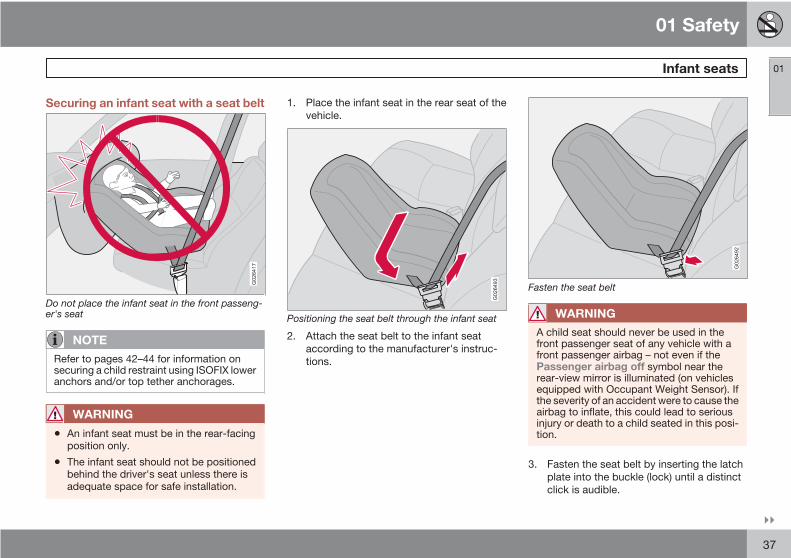
Securing an infant seat with a seat belt
G026417
Do not place the infant seat in the front passeng-er's seat
NOTE
Refer to pages 42–44 for information onsecuring a child restraint using ISOFIX loweranchors and/or top tether anchorages.
WARNING
• An infant seat must be in the rear-facingposition only.
• The infant seat should not be positionedbehind the driver's seat unless there isadequate space for safe installation.
1. Place the infant seat in the rear seat of thevehicle.
G026493
Positioning the seat belt through the infant seat
2. Attach the seat belt to the infant seataccording to the manufacturer's instruc-tions.
G026492
Fasten the seat belt
WARNING
A child seat should never be used in thefront passenger seat of any vehicle with afront passenger airbag – not even if thePassenger airbag off symbol near therear-view mirror is illuminated (on vehiclesequipped with Occupant Weight Sensor). Ifthe severity of an accident were to cause theairbag to inflate, this could lead to seriousinjury or death to a child seated in this posi-tion.
3. Fasten the seat belt by inserting the latchplate into the buckle (lock) until a distinctclick is audible.
01 Safety
Infant seats01
38
G026494
Pull out the shoulder section of the seat belt
4. Pull the shoulder section of the seat beltout as far as possible to activate the belt'sautomatic locking function.
NOTE
The locking retractor will automaticallyrelease when the seat belt is unbuckled andallowed to retract fully.
5. Press the infant seat firmly in place, let theseat belt retract and pull it taut. A soundfrom the seat belt retractor's automaticlocking function will be audible at this time
and is normal. The seat belt should now belocked in place.
G026498
Ensure that the seat is securely in place
WARNING
It should not be possible to move the childrestraint more than 1 in. (2.5 cm) in anydirection.
6. Push and pull the infant seat to ensure thatit is held securely in place by the seat belt.
7. The infant seat can be removed by unbuck-ling the seat belt and letting it retract com-pletely.

01 Safety
Convertible seats 01
39
Securing a convertible seat with a seatbelt
G026420
Do not place the convertible seat in the front pas-senger's seat
NOTE
Refer to pages 42–44 for information onsecuring a child restraint using ISOFIX loweranchors and/or top tether anchorages.
Convertible seats can be used in either a for-ward or rearward-facing position, dependingon the age and size of the child.
WARNING
Always use a convertible seat that is suita-ble for the child's age and size. See theconvertible seat manufacturer's recommen-dations.
G026503
Route the seat belt through the convertible seat
WARNING
A small child's head represents a consider-able part of its total weight and its neck isstill very weak. Volvo recommends that chil-dren up to age 4 travel, properly restrained,facing rearward. In addition, Volvo recom-mends that children should ride rearwardfacing, properly restrained, as long as pos-sible.
WARNING
• Convertible child seats should be instal-led in the rear seat only.
• A rear-facing convertible seat should notbe positioned behind the driver's seatunless there is adequate space for safeinstallation.
1. Place the convertible seat in the rear seatof the vehicle.

01 Safety
Convertible seats01
40
G026500
Fasten the seat belt
2. Attach the seat belt to the convertible seataccording to the manufacturer's instruc-tions.
3. Fasten the seat belt by inserting the latchplate into the buckle (lock) until a distinctclick is audible.
4. Pull the shoulder section of the seat beltout as far as possible to activate the belt'sautomatic locking function.
NOTE
The locking retractor will automaticallyrelease when the seat belt is unbuckled andallowed to retract fully.
5. Press the convertible seat firmly in place,let the seat belt retract and pull it taut. Asound from the seat belt retractor's auto-matic locking function will be audible at thistime and is normal. The seat belt shouldnow be locked in place.
G026501
Pull out the shoulder section of the seat belt
6. Push and pull the convertible seat toensure that it is held securely in place bythe seat belt.
WARNING
It should not be possible to move the childrestraint more than 1 in. (2.5 cm) in anydirection.
The convertible seat can be removed byunbuckling the seat belt and letting it retractcompletely.
G026502
Ensure that the seat is securely in place

01 Safety
Booster cushions 01
41
Securing a booster cushion
G026489
Position the child correctly on the booster cushionand fasten the seat belt
WARNING
A child seat should never be used in thefront passenger seat of any vehicle with afront passenger airbag – not even if thePassenger airbag off symbol near therear-view mirror is illuminated (on vehiclesequipped with Occupant Weight Sensor). Ifthe severity of an accident were to cause theairbag to inflate, this could lead to seriousinjury or death to a child seated in this posi-tion.
Booster cushions are recommended for chil-dren who have outgrown convertible seats.
1. Place the booster cushion in the rear seatof the vehicle.
2. With the child properly seated on thebooster cushion, attach the seat belt to oraround the cushion according to the man-ufacturer's instructions.
3. Fasten the seat belt by inserting the latchplate into the buckle (lock) until a distinctclick is audible.
4. Ensure that the seat belt is pulled taut andfits snugly around the child.
WARNING
• The hip section of the three-point seatbelt must fit snugly across the child'ships, not across the stomach.
• The shoulder section of the three-pointseat belt should be positioned acrossthe chest and shoulder.
• The shoulder belt must never be placedbehind the child's back or under thearm.
01 Safety
ISOFIX lower anchors01
42
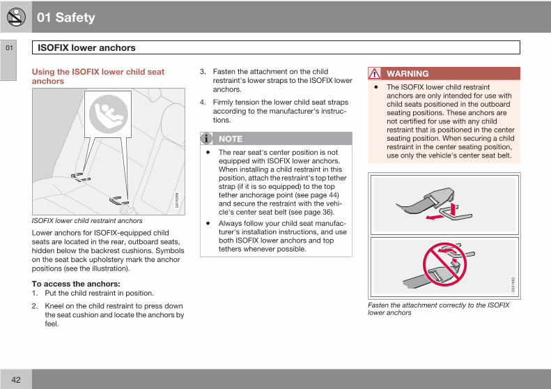
Using the ISOFIX lower child seatanchors
G015268
ISOFIX lower child restraint anchors
Lower anchors for ISOFIX-equipped childseats are located in the rear, outboard seats,hidden below the backrest cushions. Symbolson the seat back upholstery mark the anchorpositions (see the illustration).
To access the anchors:1. Put the child restraint in position.
2. Kneel on the child restraint to press downthe seat cushion and locate the anchors byfeel.
3. Fasten the attachment on the childrestraint's lower straps to the ISOFIX loweranchors.
4. Firmly tension the lower child seat strapsaccording to the manufacturer's instruc-tions.
NOTE
• The rear seat's center position is notequipped with ISOFIX lower anchors.When installing a child restraint in thisposition, attach the restraint's top tetherstrap (if it is so equipped) to the toptether anchorage point (see page 44)and secure the restraint with the vehi-cle's center seat belt (see page 36).
• Always follow your child seat manufac-turer's installation instructions, and useboth ISOFIX lower anchors and toptethers whenever possible.
WARNING
• The ISOFIX lower child restraintanchors are only intended for use withchild seats positioned in the outboardseating positions. These anchors arenot certified for use with any childrestraint that is positioned in the centerseating position. When securing a childrestraint in the center seating position,use only the vehicle's center seat belt.
G031682
Fasten the attachment correctly to the ISOFIXlower anchors
01 Safety
ISOFIX lower anchors 01
43
WARNING
Be sure to fasten the attachment correctlyto the anchor (see the illustration). If theattachment is not correctly fastened, thechild restraint may not be properly securedin the event of a collision.
01 Safety
Top tether anchors01
44
Top tether anchors
G029703
Top tether anchorage points
Volvo vehicles are equipped with child restrainttop tether anchorages in the rear seating posi-tions. They are located on the rear sides of thebackrests.
Using the top tether anchorages1. Place the child restraint on the rear seat.
2. Attach the hook to the anchorage.
G026487
Route the strap under the head restraint
WARNING
Be sure to fasten the child tether attachmentcorrectly to the anchor. If it is not correctlyfastened, the child seat may not be properlyrestrained in the event of a collision.
3. Route the top tether strap under the headrestraint and fasten its attachment to theanchorage.
4. Firmly tension the top tether strap accord-ing to the child restraint manufacturer'sinstructions. Tension the top tether straponly after the lower anchor straps or theseat belt have been firmly tensioned.
See page 42 for information on securing thechild restraint to ISOFIX lower anchors.
WARNING
• Never route a top tether strap over thetop or around the head restraint. Itshould always be routed under the headrestraint.
• Child restraint anchorages are designedto withstand only those loads imposedby correctly fitted child restraints. Underno circumstances are they to be usedfor adult seat belts or harnesses. Theanchorages are not able to withstandexcessive forces on them in the event ofcollision if full harness seat belts or adultseat belts are installed to them. An adultwho uses a belt anchored in a childrestraint anchorage runs a great risk ofsuffering severe injuries should a colli-sion occur.
• Do not install rear speakers that requirethe removal of the top tether anchors orinterfere with the proper use of the toptether strap.

01 Safety
Child restraint registration and recalls 01
45
Registering a child restraintChild restraints could be recalled for safetyreasons. You must register your child restraintto be reached in a recall. To stay informedabout child safety seat recalls, be sure to fill outand return the registration card that comeswith new child restraints.
Child restraint recall information is readily avail-able in both the U.S. and Canada. For recallinformation in the U.S., call the U.S. Govern-ment's Auto Safety Hotline at 1-800-424-9393.In Canada, visit Transport Canada's ChildSafety website at http://www.tc.gc.ca/roadsafety/childsafety/menu.htm.

G020901
46
Instrument overview................................................................................ 48Instrument panel..................................................................................... 51Indicator and warning symbols............................................................... 53Symbols – instrument panel.................................................................... 55Information display.................................................................................. 5812-volt sockets........................................................................................ 60Lighting panel.......................................................................................... 61Left-side steering wheel lever................................................................. 64Trip computer.......................................................................................... 66Cruise control (option)............................................................................. 68Right-side steering wheel lever............................................................... 70Steering wheel adjustment, Hazard warning flashers............................. 73Parking brake.......................................................................................... 74Power windows....................................................................................... 75Mirrors..................................................................................................... 77Power moonroof (option)........................................................................ 80Personal settings..................................................................................... 82HomeLink® Wireless Control System (option)....................................... 85

02INSTRUMENTS AND CONTROLS
02 Instruments and controls
Instrument overview
02
48
G01
9488

02 Instruments and controls
Instrument overview
02
49
Steering wheel adjustment
Hood opener
Controls in front doors (seepage 50)
Left steering wheel lever
Lighting panel, fuel filler dooropener
Door open handle and locking but-ton
Climate system air vent
Side window air vent
Cruise control
Horn, airbag
Main instrument panel
Audio controls (option)
Right steering wheel lever
Ignition switch
Moonroof control (option)
Not in use
Not is use
Courtesy lighting switch
Driver's side reading light
Passenger's side reading light
Seat belt reminder and OccupantWeight Sensor indicator
Rear-view mirror
Display for climate control, personalsettings, and audio system
Audio system
Controls for personal settings andaudio system
Controls for climate system
Gear selector
Hazard warning flashers
Door open handle, and locking but-ton
Glove compartment
Parking brake
12-volt socket
Position for optional equipment
Position for optional equipment
02 Instruments and controls
Instrument overview
02
50
Control panel in driver's door
G017435
Lockout switch for rear windows
Power windows
Door mirror button, driver's side
Door mirror adjustment control
Door mirror button, passenger'sside

02 Instruments and controls
Instrument panel
02
51
Instrument panel
8 9 11 12 13 1410 G03
1465
432 5 6 71
Speedometer
Turn signal, left
Warning symbol – See the following pagesfor additional information.
Information display – The display presentsinformation and warning messages, theambient temperature, clock, etc. When theambient temperature is between 23 °F and36 °F (–5 °C and +2 °C), a snowflake sym-bol is shown in the display. This symbolserves as a warning for possible slipperyroad surfaces. Please note that this symboldoes not indicate a fault with your car. Atlow speeds, or when the car is not moving,
the temperature readings may be slightlyhigher than the actual ambient tempera-ture.
Information symbol – See the followingpages for additional information.
Turn signal, right
Tachometer – Shows engine speed inthousands of revolutions per minute (rpm).Do not drive continuously with the needlein the red area of the dial, which indicatesmaximum allowable engine rpm range.Instead, shift to a higher gear or slow thevehicle down. The engine managementsystem will automatically prevent exces-
sively high engines speeds. This will benoticeable as a pronounced unevenness inengine speed.
Indicator and warning symbols
Fuel gauge, see page 267 for fuel tank vol-ume. When a warning light in the gaugecomes on, the vehicle should be refueledas soon as possible. see page 66 formore information on fuel level and con-sumption in the "Trip computer” section.
High beam indicator
Function display – This window displaysinformation on functions such as the

02 Instruments and controls
Instrument panel
02
52
odometer, trip odometers, optional rainsensor, and cruise control.
Trip odometer reset button – The tripodometers are used to measure short dis-tances. Press the button briefly to switchbetween the odometer for the car's totalmileage and the two trip odometers, T1and T2. A long press (more than 2 seconds)resets the currently selected trip odometer.
Temperature gauge – The gauge indicatesthe temperature of the engine cooling sys-tem. If the temperature is abnormally highand the needle enters the red zone, a mes-sage is shown in the display. Bear in mindthat auxiliary lamps in front of the air intakereduce the cooling capacity at high outsidetemperatures and high engine loads.
Indicator and warning symbols

02 Instruments and controls
Indicator and warning symbols
02
53
Function checkThe indicator and warning symbols1 light upwhen you turn the ignition key or the optionalkeyless drive start control to the driving posi-tion (position II) before starting. This shows thatthe symbols are functioning.
When the engine starts, all sym-bols go out. If the engine is notstarted within 5 seconds, all of thesymbols except the malfunctionindicator light (CHECK ENGINE)and the oil pressure warning lightwill go out. Certain symbols may
not have their functions illustrated, dependingon the car's equipment.
CHECKENGINE
The PARK BRAKE symbol will not go out untilthe parking brake has been released.
Symbols in the center of the instrumentpanel
G026365
Warning symbolThe red warning symbol lights upto indicate a fault that could affectthe car's drivability.This symbolilluminates when the vehicle istraveling at speeds above 5 mph
(7 km/h). A text explaining the nature of the faultwill also be shown in the information display.The symbol and accompanying text will remainon until the fault has been corrected. This sym-bol may also light up in combination with otherindicator or warning symbols.
If the red warning symbol lights up:
1. Stop the car as soon as possible in a suit-able location.
2. Read the message in the information dis-play.
3. Follow the instructions provided, or con-tact a trained and qualified Volvo servicetechnician. Erase the message by pressingREAD, see page 58.
Information symbolThe yellow information symbollights up to alert the driver to amessage in the information dis-play. This symbol illuminates whenthe vehicle is traveling at speeds
below 5 mph (7 km/h).
The message can be erased by pressing theREAD button, see page 58, or will disappearautomatically (the length of time required forthe message to disappear varies, dependingon the function indicated).
When the message "TIME FOR REGULARSERVICE" is displayed, the text can be erasedand the information symbol light can be turnedoff by pressing the READ button. The text willdisappear and the symbol light will go out auto-matically after two minutes.
1 On certain engines, the symbol for low oilpressure is not used. Instead, a text warningis provided in the information display, see page 216.

02 Instruments and controls
Indicator and warning symbols
02
54
This symbol may also light up in combinationwith other indicator or warning symbols.
NOTE
The car can still be driven after the informa-tion symbol has come on. The car can bedriven for 1–2 weeks after service-relatedinformation has been displayed.
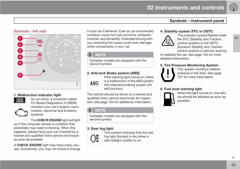
02 Instruments and controls
Symbols – instrument panel
02
55
Symbols – left side
G026439
1. Malfunction indicator lightAs you drive, a computer calledOn-Board Diagnostics II (OBDII)monitors your car's engine, trans-mission, electrical and emissionsystems.
The CHECK ENGINE light will lightup if the computer senses a condition thatpotentially may need correcting. When thishappens, please have your car checked by atrained and qualified Volvo service technicianas soon as possible.
CHECKENGINE
A CHECK ENGINE light may have many cau-ses. Sometimes, you may not notice a change
in your car's behavior. Even so, an uncorrectedcondition could hurt fuel economy, emissioncontrols, and drivability. Extended driving with-out correcting the cause could even damageother components in your car.
NOTE
Canadian models are equipped with thesecond symbol.
2. Anti-lock Brake system (ABS)If the warning light comes on, thereis a malfunction of the ABS system(the standard braking system willstill function).
The vehicle should be driven to a trained andqualified Volvo service technician for inspec-tion, see page 153 for additional information.
NOTE
Canadian models are equipped with thesecond symbol.
3. Rear fog lightThis symbol indicates that the rearfog light (located in the driver'sside taillight cluster) is on.
4. Stability system STC or DSTCThis indicator symbol flashes whenthe STC (Stability and Tractioncontrol system) or the DSTC(Dynamic Stability and Tractioncontrol system) is actively working
to stabilize the car, see page 155 for moredetailed information.
5. Tire Pressure Monitoring SystemThis system monitors inflationpressure in the tires. See page197 for more information.
6. Fuel level warning lightWhen this light comes on, the vehi-cle should be refueled as soon aspossible.
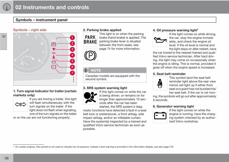
02 Instruments and controls
Symbols – instrument panel
02
56
Symbols – right side
G026438
1. Turn signal indicator for trailer (certainmarkets only)
If you are towing a trailer, this lightwill flash simultaneously with theturn signals on the trailer. If thelight does not flash when signaling,one of the turn signals on the trailer
or on the car are not functioning properly.
2. Parking brake appliedThis light is on when the parkingbrake (hand brake) is applied. Theparking brake lever is situatedbetween the front seats, seepage 74 for more information.
NOTE
Canadian models are equipped with thesecond symbol.
3. SRS system warning lightIf this light comes on while the caris being driven, or remains on forlonger than approximately 10 sec-onds after the car has beenstarted, the SRS system's diag-
nostic functions have detected a fault in a seatbelt lock or pretensioner, a front airbag, sideimpact airbag, and/or an inflatable curtain.Have the system(s) inspected by a trained andqualified Volvo service technician as soon aspossible.
4. Oil pressure warning light1
If the light comes on while driving,the car, stop the engine immedi-ately, and check the engine oillevel. If the oil level is normal andthe light stays on after restart, have
the car towed to the nearest trained and quali-fied Volvo service technician. After hard driv-ing, the light may come on occasionally whenthe engine is idling. This is normal, provided itgoes off when the engine speed is increased.
5. Seat belt reminderThis symbol (and the seat beltreminder light above the rear viewmirror) will light up if either frontseat occupant has not buckled his/her seat belt. If the car is not mov-
ing, the symbols will go out after approximately6 seconds.
6. Generator warning lightIf the light comes on while theengine is running, have the charg-ing system checked by an author-ized Volvo workshop.
1 On certain engines, this symbol is not used to indicate low oil pressure. Instead, a text warning is provided in the information display, see also page 216.

02 Instruments and controls
Symbols – instrument panel
02
57
7. Brake failure warning lightIf this light comes on while drivingor braking, stop the car as quicklyas possible in a safe place, openthe hood, and check the brake fluidlevel in the reservoir, see
page 215 for the location of the reservoir.
NOTE
Canadian models are equipped with thesecond symbol.
WARNING
If the fluid level is below the MIN mark in thereservoir or if a Brake failure – Serviceurgent message is displayed in the infor-mation display: DO NOT DRIVE. Have thecar towed to a trained and qualified Volvoservice technician and have the brake sys-tem inspected.
If the BRAKES and ABS warning lights comeon at the same time, this could indicate a faultin the brake system.
In this case:
1. Stop the car in a suitable place and switchoff the engine.
2. Restart the engine.
3. If both warning lights go off, no furtheraction is required and the car can bedriven.
4. If both lights remain on after the engine hasbeen restarted, switch off the engine againand check the brake fluid level, seepage 215 for the location of the reservoir.
Door open warningThe driver will be alerted if one of the doors, thehood or the tailgate are open or ajar.
At low speedsIf the car is moving at a speed ofless than approximately 3 mph(5 km/h), the Information symbol inthe instrument panel will light upand a message will be shown in the
information display indicating which door(s),etc is not completely closed.
At higher speedsIf the car is moving at a speedabove approximately 6 mph(10 km/h), the Warning symbol inthe instrument panel will light upand a message will be shown in the
information display indicating which door(s),etc is not completely closed.
Hood and tailgateIf the hood and/or tailgate is notcompletely closed, the Informationsymbol in the instrument panel willlight up and a message will be dis-played, regardless of the vehicle's
speed.

02 Instruments and controls
Information display
02
58
Messages
G019617
When an indicator or warning light in the instru-ment panel comes on, a message is alsoshown in the information display. To read amessage:
1. Press the READ button (1).
2. Pressing READ repeatedly enables you toscroll to any other messages that may bestored.
NOTE
If a message is displayed when e.g. you areusing the trip computer, this message mustbe read before you can access the trip com-puter.
Message Meaning
STOP SAFELYA Stop the vehicle in asafe place and switchoff the engine to helpprevent the risk of seri-ous damage.
HIGH ENGINETEMP STOPSAFELY
Stop the vehicle in asafe place and switchoff the engine to helpprevent the risk of seri-ous damage.
SERVICEURGENTA
Take your car to atrained and qualifiedVolvo service techni-cian for inspectionimmediately.
SEE MANUALA Refer to your owner'smanual. For additionalinformation, pleasecontact your Volvoretailer.
Message Meaning
SERVICEREQUIREDA
Take your car to atrained and qualifiedVolvo service techni-cian for inspection assoon as possible (butpreferably before thenext scheduled mainte-nance service).
BOOK TIMEFOR SERVICE
Book time for service atan authorized Volvoworkshop.
TIME FORREGULARMAINTE-NANCE
This message is affec-ted by the number ofmiles/km driven, by thenumber of months, orby the number of enginehours since the servicereminder was reset atthe most recent regu-larly scheduled service.
MAINTE-NANCE OVER-DUE
If the vehicle is not serv-iced according toschedule, the warrantymay not apply to dam-aged parts, etc.
02 Instruments and controls
Information display
02
59
Message Meaning
TIME FORREGULARMAINTE-NANCE
This message is affec-ted by the number ofmiles/km driven, by thenumber of months, orby the number of enginehours since the servicereminder was reset atthe most recent regu-larly scheduled service.
REMINDERCHECK OILLEVEL
Stop as soon as possi-ble and switch off theengine, check the oillevel and top up if nec-essary, see page 216.
A This is part of the message. Additional information will alsobe displayed.

02 Instruments and controls
12-volt sockets
02
60
12-volt socket (front seat)
G026349
12-volt socket, auxiliary equipment
The 12-volt socket can be used to plug in cer-tain accessories such as cellular telephones,etc. The maximum current is 10 A. The keymust be in position I (or higher) for the auxiliarysocket to function.
Ashtrays/cigarette lighterThe auxiliary socket can also be used for a cig-arette lighter1, and ashtrays, which can be pur-chased from your Volvo retailer.
NOTE
The cover should be kept on when the aux-iliary socket is not in use.
Auxiliary equipmentThe buttons to the left of the 12-volt socket canbe used for Volvo-installed optional or auxiliaryequipment.
12-volt socket (rear seat)
G029082
NOTE
The 12-volt socket in the rear seat cannotfunction as a cigarette lighter.
1 Accessory.

02 Instruments and controls
Lighting panel
02
61
G026415
Pos. Lighting
Daytime running lights off. Highbeam flash only.
Parking lights
Daytime running lights. Highbeams and high beam flash canbe used in this position.
Parking lightsThe front and rear parking lights can be turnedon even when the ignition is switched off.
Turn switch (1) to the parking light position.
The license plate lights also illuminate when theparking lights are switched on.
Headlights1. Turn the ignition key to position II.
2. The low beam headlights (daytime runninglights) illuminate automatically, exceptwhen the light switch (1) is in the parkinglight position1.
NOTE
See page 64 for information on switchingbetween high and low beams.
Active Bi-Xenon Lights (ABL)–option
G026507
Lighting panel, vehicles with Active Bi-Xenonheadlights
When the ABL function is activated, the head-light beams adjust laterally to help light up acurve according to movements of the steeringwheel.
This function can be activated by turning thelighting switch to the ABL position (indicatedby the arrow in the illustration). The indicatorlight in the ABL symbol will illuminate.The function can be deactivated by turning thelighting switch counterclockwise to one of theother lighting positions.
1 On Canadian models, the daytime running lights will remain on with the light switch in this position.

02 Instruments and controls
Lighting panel
02
62
G020789
Headlight pattern with ABL deactivated (left) andactivated (right)
NOTE
• This function can only be activated intwilight or dark conditions, and onlywhen the vehicle is in motion.
• If the indicator light flashes, this indi-cates a fault in the ABL system. A textmessage will also be displayed.
Brake lightsThe brake lights come on automatically whenthe brakes are applied.
Fog lights
Front fog lights (option)The front fog lights can be used in combinationwith either the headlights or the parking lights.
1. Turn the ignition key to position II.
2. Press button (3) to turn on the front foglights.
An indicator light in the button illuminates whenthe front fog lights are on.
Rear fog lightThe single rear fog light is located in the driver'sside taillight cluster.
The rear fog light will only function in combi-nation with the high/low beam headlights or theoptional front fog lights.
1. Turn the ignition key to position II.
2. Press button (5) to turn on the rear fog light.
An indicator light in the button illuminates whenthe rear fog light is on.
NOTE
The rear fog light is considerably brighterthan the normal taillights and should beused only when conditions such as fog, rain,snow, smoke or dust reduce visibility forother vehicles to less than 500 ft.(150 meters).
Instrument panel lightingThe instrument panel lighting illuminates whenthe ignition is in position II and the light switch(1) is in either position or .
NOTE
To make it easier to read the odometer, tripodometer, clock, and ambient temperature,these gauges illuminate when the vehicle isunlocked and when the key has beenremoved from the ignition switch. The light-ing will go out when the vehicle is locked.
Move the thumb wheel (2) up to increasebrightness or down to decrease brightness.

02 Instruments and controls
Lighting panel
02
63
Unlocking the fuel filler doorWith the ignition switched off, press button (4)to unlock the fuel filler door. Please note thatthe fuel filler door will remain unlocked until thecar begins to move forward.
An audible click will be heard when the fuel fillerdoor re-locks.
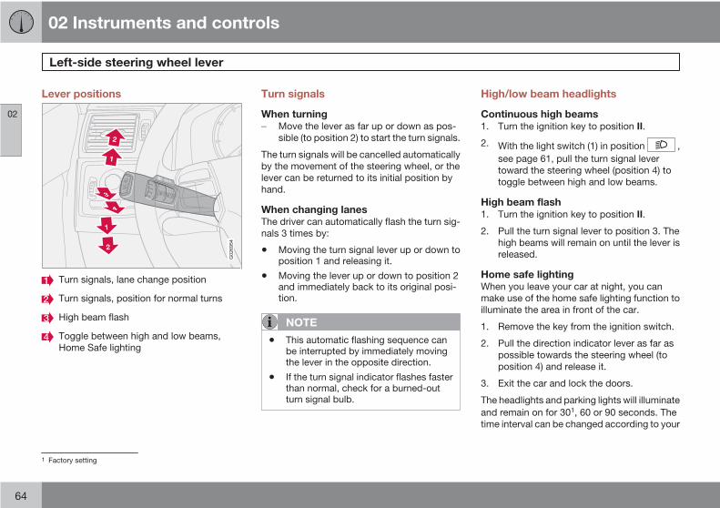
02 Instruments and controls
Left-side steering wheel lever
02
64
Lever positions
G026954
Turn signals, lane change position
Turn signals, position for normal turns
High beam flash
Toggle between high and low beams,Home Safe lighting
Turn signals
When turningMove the lever as far up or down as pos-sible (to position 2) to start the turn signals.
The turn signals will be cancelled automaticallyby the movement of the steering wheel, or thelever can be returned to its initial position byhand.
When changing lanesThe driver can automatically flash the turn sig-nals 3 times by:
• Moving the turn signal lever up or down toposition 1 and releasing it.
• Moving the lever up or down to position 2and immediately back to its original posi-tion.
NOTE
• This automatic flashing sequence canbe interrupted by immediately movingthe lever in the opposite direction.
• If the turn signal indicator flashes fasterthan normal, check for a burned-outturn signal bulb.
High/low beam headlights
Continuous high beams1. Turn the ignition key to position II.
2. With the light switch (1) in position ,see page 61, pull the turn signal levertoward the steering wheel (position 4) totoggle between high and low beams.
High beam flash1. Turn the ignition key to position II.
2. Pull the turn signal lever to position 3. Thehigh beams will remain on until the lever isreleased.
Home safe lightingWhen you leave your car at night, you canmake use of the home safe lighting function toilluminate the area in front of the car.
1. Remove the key from the ignition switch.
2. Pull the direction indicator lever as far aspossible towards the steering wheel (toposition 4) and release it.
3. Exit the car and lock the doors.
The headlights and parking lights will illuminateand remain on for 301, 60 or 90 seconds. Thetime interval can be changed according to your
1 Factory setting

02 Instruments and controls
Left-side steering wheel lever
02
65
preferences by using the Personal Settingsfunction, see page 82 for more information.

02 Instruments and controls
Trip computer
02
66
G029052
READ (press to acknowledge/confirm/erase a message)
Thumb wheel (used to scroll among the tripcomputer menus)
RESET
The trip computer stores information gatheredfrom several systems in your car and has fourmenus (five on Canadian models) that can beshown in the information display.
• MILES TO EMPTY TANK
• AVERAGE (average fuel consumption)
• INSTANTANEOUS (current fuel con-sumption)
• AVERAGE SPEED
• ACTUAL SPEED (current speed in mph,Canadian models only)
• STC/DSTC, see page 155
NOTE
Warning messages from the car's monitor-ing systems will override the trip computerfunction.
If a warning message is shown in the informa-tion display while you are using the trip com-puter:
1. Acknowledge the message by pressing theREAD (button 1).
2. Press READ again to return to the tripcomputer function.
ControlsThe trip computer functions can be accessedby twisting the thumb wheel (2) one step at atime in either direction. Twisting a final timereturns you to the original function.
ResettingAVERAGE (average fuel consumption) andAVERAGE SPEED can be reset.
1. Select one of these functions.
2. Press RESET (3).
MILES TO EMPTY TANKThis function shows the approximate distancethat can be driven on the fuel remaining in thetank. The calculation is based on average fuelconsumption during the last 20 miles (30 km)of driving and the amount of fuel remaining inthe tank when the reading was taken.
When the message ---- miles to empty tankappears in the display, refuel as soon as pos-sible.
AVERAGEThis value indicates fuel consumption since thelast time the trip computer was reset, by press-ing RESET (button 3). When the engine isswitched off, information on fuel consumptionis stored and remains in system memory untilRESET (button 3) is pressed again.
INSTANTANEOUSThis value indicates the current fuel consump-tion, based on readings taken once per sec-ond. When the car is not moving, "----" will bedisplayed.
AVERAGE SPEEDThis value indicates average speed since thelast time the trip computer was reset, by press-ing RESET (button 3). When the engine isswitched off, information on average speed isstored and remains in system memory until theRESET (button 3) is pressed again.
02 Instruments and controls
Trip computer
02
67
ACTUAL SPEED (Canadian models only)This function provides the driver with an instan-taneous conversion of the car's current speedfrom km/h to mph.
NOTE
Trip computer readings may vary slightlydepending on the circumference of the tireson the car, tire inflation, or driving style.

02 Instruments and controls
Cruise control (option)
02
68
Engaging the cruise control function
G020141
The cruise control buttons are located on theleft side of the steering wheel hub.
NOTE
This does not set the vehicle's speed.
1. Press the CRUISE button. CRUISE willappear in the function display in the centerof the instrument panel.
2. Press + or – to set the current speed.CRUISE ON will be displayed.
Increasing or decreasing speed
G031667
Use + or – in the following ways to increase ordecrease the vehicle's speed:
1. Press and hold down + or – until the vehiclereaches the desired speed. This willbecome the set speed when the button isreleased.
2. Press + or – for approximately a half sec-ond and release the button to increase ordecrease vehicle speed by approximately1 mph (1.6 km/h).
NOTE
• Cruise control will not function atspeeds below 20 mph (30 km/h).
• Momentary acceleration, for less than1 minute (e.g. when passing anothercar), does not affect cruise control oper-ation. The car will automatically returnto the previously set speed when theaccelerator pedal is released.
Temporarily disengaging the cruisecontrol• Press 0 to temporarily disengage cruise
control.
CRUISE will appear in the function display.The currently set speed is stored in the sys-tem's memory.
Cruise control is also automaticallydisengaged:• If the speed drops below approximately
20 mph (30 km/h) when driving uphill.
• When the brake or clutch pedal isdepressed.
• If the gear selector is moved to posi-tion N.

02 Instruments and controls
Cruise control (option)
02
69
• During wheel spin or wheel lock-up.
• If the vehicle's speed is increased by usingthe accelerator pedal for more than 1minute.
Returning to the set speedPress the button to resume thepreviously set speed. CRUISEON will be displayed.
Disengaging cruise controlCruise control can also be disengaged by:
• Pressing the CRUISE button (CRUISEON will no longer be shown in the functiondisplay).
• Putting the gear selector in Neutral (N).
WARNING
Cruise control should not be used in heavytraffic or when driving on wet or slipperyroads. Cruise control may not maintain setspeed on steep downgrades.

02 Instruments and controls
Right-side steering wheel lever
02
70
Windshield wipers
0
0
A
C DB
G025411
Windshield/headlight washers
Rain sensor (option) – on/of, see page 70
Thumb wheel
Tailgate wiper/washer
Windshield wipers offThe windshield wipers are off whenthe lever is in position 0.
Manual wiper functionFrom position 0, move the leverupward. The windshield wipers willsweep one stroke at a time for aslong as the lever is held up.
Intermittent wiper functionWith the lever in this position, youcan set the wiper interval by mov-ing the thumb wheel (C) upward toincrease wiper speed or down-ward to decrease the speed.
Continuous wiper functionThe wipers operate at "normal"speed.
High speed wiper function.
A–Windshield washersPull the lever toward the steering wheel andrelease it. The wipers will make 2–3 sweepsacross the windshield after the lever has beenreleased.
CAUTION
• Use ample washer fluid when washingthe windshield. The windshield shouldbe thoroughly wet when the wipers arein operation.
• Before using the wipers, ice and snowshould be removed from the wind-shield/rear window. Be sure the wiperblades are not frozen in place.
Headlight washers (certain models)When the lever has been pulled, high pressurejets mounted in the bumper will spray the head-lights.
The following applies to conserve washer fluid,see page 61 for information on the light switchpositions:
Low/high beam headlights onThe headlights will be washed the first time thewindshield is washed. Thereafter, the head-lights will only be washed once for every fivetimes the windshield is washed within a 10-minute period.
Parking lights onOptional Bi-Xenon headlights will be washedonce for every five times the windshield iswashed.
Normal halogen headlights will not be washed.
02 Instruments and controls
Right-side steering wheel lever
02
71
B – Rain sensor (option)
G026422
The rain sensor regulates windshield wiperspeed according to the amount of water on thewindshield. The sensitivity of the rain sensor isadjusted by moving the thumb wheel (C in theillustration on the previous page) up (the wiperswill sweep the windshield more frequently) ordown (the wipers will sweep the windshieldless frequently).
On/Off
Activating the rain sensor1. Switch on the ignition.
2. Put the windshield wiper lever in position0.
3. Press button B (see page 70). The rain sen-sor symbol will appear in the lower display.
Manual deactivationThe rain sensor can be deactivated by:
• Pressing button (B).
or
• Moving the windshield wiper lever down.
NOTE
The rain sensor function will remain acti-vated if the lever is briefly moved up toactivate the "manual sweep" function.
CAUTION
The rain sensor should be deactivated whenwashing the car in an automatic car wash,etc. If the rain sensor function is left on, thewipers will start inadvertently in the carwash and could be damaged.
Automatic deactivationThe rain sensor is deactivated automatically inthe following situations:
• When the key is removed from the ignition.
• Five minutes after the ignition is switchedoff if the key is left in the ignition.
C – Thumb wheelThe thumb wheel is used to set the wiper inter-val when intermittent wiping is selected, or thesensitivity to the amount of rain on the wind-shield when the rain sensor is selected. Movethe wheel upward or downward to increase/decrease wiper speed when the intermittentfunction is selected, or to increase/decreasethe optional rain sensor's sensitivity when thethis function is activated.
D – Tailgate wiper/washerPress the lever forward to wipe and wash thetailgate window. The wiper will sweep the win-dow several times after the lever has beenreleased.
The button at the end of the lever has threepositions:
• Intermittent wiping: Press in the upper sec-tion of the button.
• Normal wiper speed: Press in the lowersection of the button.
• Neutral position: The wiper function isswitched off.
02 Instruments and controls
Right-side steering wheel lever
02
72
Tailgate wiper and reverse gear• If the front wipers are on and the transmis-
sion is put into reverse gear, the tailgatewiper will be activated.
• If the transmission is in reverse and themanual windshield wiper function is used(the lever is pushed upward), the tailgatewiper will also be activated for as long thelever is held up.
• If the tailgate wiper is already in normalwiping function, the normal wiping functionwill continue.
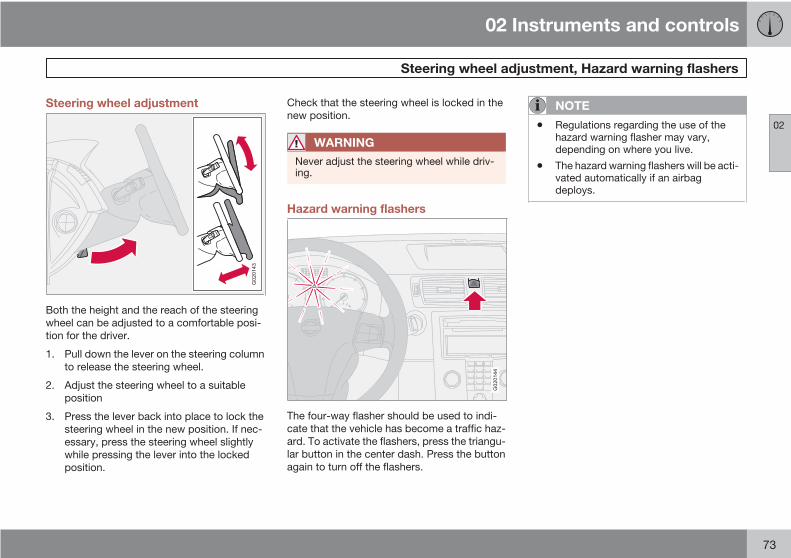
02 Instruments and controls
Steering wheel adjustment, Hazard warning flashers
02
73
Steering wheel adjustment
G020143
Both the height and the reach of the steeringwheel can be adjusted to a comfortable posi-tion for the driver.
1. Pull down the lever on the steering columnto release the steering wheel.
2. Adjust the steering wheel to a suitableposition
3. Press the lever back into place to lock thesteering wheel in the new position. If nec-essary, press the steering wheel slightlywhile pressing the lever into the lockedposition.
Check that the steering wheel is locked in thenew position.
WARNING
Never adjust the steering wheel while driv-ing.
Hazard warning flashers
G020144
The four-way flasher should be used to indi-cate that the vehicle has become a traffic haz-ard. To activate the flashers, press the triangu-lar button in the center dash. Press the buttonagain to turn off the flashers.
NOTE
• Regulations regarding the use of thehazard warning flasher may vary,depending on where you live.
• The hazard warning flashers will be acti-vated automatically if an airbagdeploys.

02 Instruments and controls
Parking brake
02
74
Parking brake (hand brake)
G026348
The parking brake lever is located between thefront seats.
NOTE
The indicator light will illuminate even if theparking brake has only been partiallyapplied.
When applying the parking brake1. Press firmly on the brake pedal.
2. Pull the parking brake lever up firmly to itsfull extent.
3. Release the brake pedal and ensure thatthe vehicle is at a standstill.
4. If the vehicle rolls, the parking brake levermust be pulled more firmly.
5. When parking a vehicle always put the gearselector in first gear (for manual transmis-sion) or P (for automatic transmission).
Parking on a hill• If the vehicle is pointing uphill, turn the front
wheels so that they point away from thecurb.
• If the vehicle is pointing downhill, turn thefront wheels so that they point toward thecurb.
Releasing the parking brake1. Press firmly on the brake pedal.
2. Pull the lever up slightly, press the buttonat the end of the lever and lower the levercompletely.
WARNING
Pull up the parking brake lever up firmly toits full extent.

02 Instruments and controls
Power windows
02
75
Operation
G017439
Control panel in driver's door
Open/close front windows
Open/close rear windows
The power windows are controlled by buttonsin the arm rests.
• The ignition must be ON (ignition key inposition I, II or the engine running) for thepower windows to function.
• The power windows will also function afterthe ignition has been switched off as longas neither of the front doors has beenopened.
Opening a windowLightly press down the front edge of any of thebuttons (A or B) to the first detent ("stop") toopen a window to the position of your choice.
WARNING
• Always remove the ignition key whenthe vehicle is unattended.
• Never leave children unattended in thevehicle.
• Make sure that the windows are com-pletely unobstructed before they areoperated.
• Press the front part of any of the buttons (Aor B) as far down as possible and releaseto automatically open the window com-pletely.
• To stop the window at any time, pull thebutton up.
NOTE
To reduce buffeting wind noise if the rearwindows are opened, also open the frontwindows slightly.
Closing a window• Lightly pull up the front edge of any of the
buttons (A or B) to the first detent ("stop")
to close a window to the position of yourchoice.
• Pull the front part of any of the buttons (Aor B) up as far as possible and release toautomatically close the window com-pletely. To stop the window at any time,press the button down.
Lockout switch for rear windows
G017440
Lockout switch
The electrically operated rear door windowscan be disabled by a switch located on thedriver's door (see illustration).
If the light in the switch is OFF: The rear doorwindows can be raised or lowered with the

02 Instruments and controls
Power windows
02
76
buttons on the rear door armrests or with thebuttons on the driver's door armrest.
If the light in the switch is ON: The rear doorwindows can only be raised or lowered with thebuttons on the driver's door.
Power window control – frontpassenger's side
G019511
The control for the power window in the frontpassenger's door operates that window only.
Power window controls – rear doors
G028208
The rear door windows can be operated withthe control on each door and with the switchon the driver's door.

02 Instruments and controls
Mirrors
02
77
Rearview mirror
G020146
Day/night control
Normal position
Night position, reduces glare from follow-ing traffic
Night positionTo reduce glare from the headlights of follow-ing vehicles, use control (1) to switch betweenthe normal and night-driving positions.
Auto-dim function (option)An optional integrated sensor reacts to head-lights from following traffic and automaticallyreduces glare.
Rearview mirror with compass (option)
G029930
The upper right-hand corner of the rearviewmirror has an integrated display that shows thecompass direction toward which the car ispointing. Eight different directions can be dis-played: N, NE, E, SE, S, SW, W and NW. Thedisplay shows your car's orientation withrespect to true north.
Calibrating the compass
G031045
The earth is divided into 15 magnetic zones.The compass is initially set for the zone towhich the car was delivered, and shouldalways be adjusted if the car is driven to a newmagnetic zone. A "C" will be displayed if cali-bration becomes necessary.
To calibrate the compass:
1. Stop the car in a large, open area, awayfrom traffic.
2. Using a pen or similar object, hold the but-ton (1) depressed for at least 6 seconds."C" will be displayed.

02 Instruments and controls
Mirrors
02
78
G026409
Magnetic zones
3. Press button (1) for at least 3 seconds todisplay the number of the current magneticzone.
4. Press button (1) repeatedly until the num-ber for the required geographical area(1 – 15) is displayed. "C" will be displayedagain.
5. Drive slowly in a circle at a maximum speedof 6 mph (10 km/h) until a compass direc-tion is displayed.
Calibration is complete.
Power door mirrors
G018252
The mirror control switches are located on thedriver's door armrest.
The mirror control switches are located on thedriver's door armrest.
Adjusting the mirrors
WARNING
• The mirrors should always be adjustedprior to driving.
• Objects seen in the passenger's sidewide-angle door mirror are closer thanthey appear to be.
Driver's door mirror:Press the L button (a light in the switch willgo on) to activate the adjustment control.Use this control to adjust the driver's doormirror.
Passenger's door mirror:1. Press the R switch (a light in the switch will
go on) to activate the adjustment control.Use this control to adjust the passenger'sdoor mirror.
2. After you have adjusted the mirror(s), pressthe L or R switch again (the LED will go out)to deactivate the adjustment control.
Storing the mirrors' positionThe position of the door mirrors is stored whenthe vehicle is locked. The next time the driver'sdoor is unlocked with the same remote controland that door is opened within 2 minutes, theoptional power driver's seat and side door mir-rors will automatically move to the position thatthey were in when the doors were mostrecently locked with the same remote control.
Folding power door mirrors (option oncertain markets only)The mirrors can be folded in for parking/drivingin narrow spaces.

02 Instruments and controls
Mirrors
02
79
Folding the mirrors in1. Press down the L and R mirror control but-
tons on the driver's door at the same time.
2. Release them after approximately one sec-ond. The mirrors automatically fold in to thefully retracted position.
Folding the mirrors outFold out the mirrors by pressing down the Land R buttons at the same time. The mirrorsautomatically fold out to the fully extendedposition.
Automatic foldingWhen the vehicle is locked/unlocked with theremote control or with the optional keylessdrive system (see page 123), the power doormirrors with automatically fold in or out.
NOTE
The door mirrors will not fold out automati-cally when the vehicle is unlocked if theywere folded in using the buttons on the driv-er's door control panel.
This function can be activated/deactivated inPersonal settings (see page 82). In the menusystem, go to Car settings Fold mirr. whenlocking.
Return to "neutral" positionIf a mirror has been inadvertently moved (bum-ped in a parking lot, etc.) from its original (neu-tral) position, it must be moved back to thisposition before automatic folding will functionagain.
To so so:
1. Fold in the mirrors by pressing the L andR mirror control buttons on the driver'sdoor at the same time.
2. Fold them out again by pressing the L andR mirror control buttons.
This returns the mirrors to their original (neutral)positions.
Blind Spot Information System (BLIS) -optionThe Blind Spot Information System (BLIS) is aninformation system that indicates the presenceof another vehicle in the side-view mirror's"blind area." See page 164 for detailed infor-mation.

02 Instruments and controls
Power moonroof (option)
02
80
Operating the moonroof
G007503
To operate the moonroof, the ignition key mustfirst be turned to the intermediate or drive posi-tion (position I, II or the engine running). Themoonroof can be opened in two ways:
Tilt position
Sliding moonroof
G029222
Moonroof control in the ceiling console
Auto open
Manual open
Manual close
Auto close
Tilt open
Tilt close
Tilt positionOpen: Press the rear edge of the controlupward to position 5.
Close: Pull the rear edge of the control down toposition 6.
Sliding moonroof
Auto open/closeOpen: Pull the switch as far back as possible(to position 1) and release it to automaticallyslide open the moonroof.
Close: Push the switch as far forward as pos-sible (to position 4) and release it to automati-cally close the moonroof.
Manual open/closeOpen: Pull the switch back to the first stop(position 2) and hold it until the moonroof hasopened to the position of your choice.
Close: Push the switch forward to the first stop(position 3) and hold it until the moonroof hasclosed to the position of your choice, or hasclosed completely.
NOTE
If the moonroof is repeatedly obstructedduring auto-close operation, an overloadcircuit breaker will temporarily halt moon-roof function. The moonroof will return tonormal function after a brief cool-downperiod.

02 Instruments and controls
Power moonroof (option)
02
81
CAUTION
• Remove ice and snow before openingthe moonroof.
• Do not operate the moonroof if it is fro-zen closed.
• Never place heavy objects on themoonroof.
WARNING
• If the moonroof is obstructed duringauto-close operation, it will automati-cally reverse direction and return to itsstarting position.
• During manual closing, if the moonroofis obstructed, immediately open itagain.
WARNING
• Never open or close the moonroof if it isobstructed in any way.
• Never allow a child to operate themoonroof.
• Never extend any object or body partthough the open moonroof, even if thevehicle's ignition is completelyswitched off.
• Never leave a child alone in a vehicle.
Visor
G020157
The optional moonroof features a sliding visor.The visor slides open automatically when themoonroof is opened, and must be closed man-ually.

02 Instruments and controls
Personal settings
02
82
Control panel
A
D
B
C
EG
0263
07
Display
Menu button
Exit button
Enter button
Menu navigation controls
Personal settings can be made for some of thecar's functions, such as the central lockingsystem, climate control, and the audio system.Please refer to page 241 for more informationon the audio functions that can be adjusted.The settings are presented in the display (A).
To access the menu and adjust settings1. Press MENU (B).
2. Scroll to Car Settings using the menu nav-igation control (E).
3. Press ENTER (D).
4. Select an alternative using the menu navi-gation control (E).
5. Confirm your selection by pressingENTER.
To exit the menuPress EXIT (C).
Available settings
Clock adjustTo set the time:
1. Use the number keys or the up/down arrowkeys on the navigation control (E) tochange the hour or minute.
2. Select hour(s) or minute(s) to be changedwith the left/right arrow keys.
3. Press ENTER to start the clock.
NOTE
If you are currently using the 12-hour timesetting, use the up/down arrow keys toselect AM/PM after the minute-setting hasbeen adjusted.
Lock confirmation lightWhen the car is locked/unlocked with theremote control, the direction indicators can beselected to flash to confirm the action. Thealternatives On/Off are available for both lock-ing and unlocking.
AutolockWhen the car starts to move, the doors andtailgate can be locked automatically. The alter-natives On/Off are available.
NOTE
Pulling the handle twice on a door unlocksand opens that door.
UnlockThere are two alternatives for unlocking:

02 Instruments and controls
Personal settings
02
83
• Global (All doors) – unlocks all doors andthe tailgate with one press on the remotecontrol.
• Two Step (Two-stage unlocking) – Thisalternative unlocks the driver's door withone press on the remote control. A secondpress unlocks the passenger's door andthe tailgate.
Automatically folding the door mirrorsThe setting makes it possible to automaticallyfold the door mirrors in or out when the vehicleis locked or unlocked. See page 78.
Operating side windowsThe following alternative can be selected foropening all side windows at the same time bypressing and holding the Unlock switch ineither of the front doors (see page 127 foradditional information) 1
NOTE
The ignition key must be in position I orhigher (see page 143) before all side win-dows can be opened using the switches inthe front doors.
• Auto open all windows On/Off
Temporarily turning off the alarmsensor(s)The alarm sensors can be temporarily turnedoff (if, for example, a person or a pet remainsin the vehicle when the doors are locked fromoutside with the remote control). There are twoalternatives:Activate once and Ask on exit,see page 118 and 130 .
Approach lightingThis alternative determines the length of timefor which the car's lights will remain on whenthe Approach light button on the central lock-ing system's remote control is pressed. Inter-vals of 30/60/90 seconds may be selected, seeteh section "Remote control functions" formore information.
Home safe lightingThis alternative determines the length of timefor which the car's lights will remain on whenthe high beam lever on the steering column ispulled toward the wheel with the ignitionswitched off. Intervals of 30/60/90 secondsmay be selected, see page 64 for informationon using this function.
Information• VIN number – The VIN (Vehicle Identifica-
tion Number) is the car's unique identitynumber.
• Number of Keys – the number of keys reg-istered for the car is displayed here.
Climate functions• Blower speed in AUTO mode – the blower
speed can be set to AUTO mode in modelsequipped with ECC. Choose between"Low", "Normal" and "High".
• Timer for recirculation – when the timer isactive, the air recirculates in the car for 3–12 minutes depending on the ambient tem-perature. Select On/Off depending onwhether the recirculation timer is to beactive or not.
Keyless locking and unlocking (option asavailable)The following alternatives can be selected forlocking and unlocking the doors and tailgate:
• All doors – all doors are locked or unlockedat the same time.
• Doors on the same side – front and reardoors on the same side are unlockedtogether.
1 This menu alternative also makes it possible to open all side windows by pressing and holding the Unlock button on the remote control for several seconds.
02 Instruments and controls
Personal settings
02
84
• Both front doors – both front doors areunlocked together.
• One front door – either of the front doorscan be unlocked separately2.
Reset to factory settingsUse this alternative to return to the default cli-mate system settings.
2 Factory default.

02 Instruments and controls
HomeLink® Wireless Control System (option)
02
85
Introduction
G030070
The HomeLink Wireless Control System pro-vides a convenient way to replace up to threehand-held radio-frequency (RF) transmittersused to activate devices such as gate opera-tors, garage door openers, entry door locks,security systems, even home lighting. Addi-tional HomeLink information can be found onthe Internet at www.homelink.com.
WARNING
• If you use HomeLink to open a garagedoor or gate, be sure no one is near thegate or door while it is in motion.
• When programming a garage dooropener, it is advised to park outside ofthe garage.
• Do not use HomeLink with any garagedoor opener that lacks safety stop andreverse features as required by U.S.federal safety standards (this includesany garage door opener model manu-factured before April 1, 1982). A garagedoor that cannot detect an object - sig-naling the door to stop and reverse -does not meet current U.S. federalsafety standards. For more information,contact HomeLink at:www.homelink.com.
Retain the original transmitter of the RF deviceyou are programming for use in other vehiclesas well as for future HomeLink programming. Itis also suggested that upon the sale of thevehicle, the programmed HomeLink buttons beerased for security purposes. Refer to “ErasingHomeLink Buttons”.
Programming HomeLink
NOTE
Some vehicles may require the ignitionswitch to be turned on or to the second(“accessories”) position for programmingand/or operation of HomeLink. It is also rec-ommended that a new battery be placed inthe hand-held transmitter of the devicebeing programmed to HomeLink for quickertraining and accurate transmission of theradio-frequency signal.
1. Position the end of your hand-held trans-mitter 1–3 inches (5–14 cm) away from theHomeLink button you wish to programwhile keeping the indicator light in view.
2. Simultaneously press and hold both thechosen HomeLink and hand-held transmit-ter buttons until the HomeLink indicatorlight changes from a slow to a rapidly blink-ing light. Now you may release both theHomeLink and hand-held transmitter but-tons.

02 Instruments and controls
HomeLink® Wireless Control System (option)
02
86
NOTE
Some devices may require you to replacethis Programming Step 2 with proceduresnoted in the “Gate Operator / Canadian Pro-gramming” section. If the HomeLink indica-tor light does not change to a rapidlyblinking light after performing these steps,contact HomeLink at www.homelink.com.
3. Firmly press, hold for five seconds andrelease the programmed HomeLink but-ton up to two separate times to activate thedoor. If the door does not activate, pressand hold the just-trained HomeLink buttonand observe the indicator light.
• If the indicator light stays on con-stantly, programming is completeand your device should activate whenthe HomeLink button is pressed andreleased.
• If the indicator light blinks rapidly fortwo seconds and then turns to a con-stant light continue with “Program-ming” steps 4-6 to complete the pro-gramming of a rolling code equippeddevice (most commonly a garage dooropener).
4. At the garage door opener receiver (motor-head unit) in the garage, locate the “learn”or “smart” button. This can usually be
found where the hanging antenna wire isattached to the motor-head unit.
5. Firmly press and release the “learn” or“smart” button. (The name and color of thebutton may vary by manufacturer.) Thereare 30 seconds to initiate step 6.
6. Return to the vehicle and firmly press, holdfor two seconds and release the pro-grammed HomeLink button. Repeat the“press/hold/release” sequence a secondtime, and, depending on the brand of thegarage door opener (or other rolling codeequipped device), repeat this sequence athird time to complete the programmingprocess.
HomeLink should now activate your rollingcode equipped device.
Gate Operator/Canadian ProgrammingCanadian radio-frequency laws require trans-mitter signals to “time-out” (or quit) after sev-eral seconds of transmission – which may notbe long enough for HomeLink to pick up thesignal during programming. Similar to thisCanadian law, some U.S. gate operators aredesigned to “time-out” in the same manner.
If you live in Canada or you are having difficul-ties programming a gate operator or garagedoor opener by using the “Programming” pro-
cedures, replace “Programming HomeLink”step 2 with the following:
• Continue to press and hold the HomeLinkbutton while you press and release -every two seconds (“cycle”) your hand-held transmitter until the HomeLink indica-tor light changes from a slow to a rapidlyblinking light. Now you may release boththe HomeLink and hand-held transmitterbuttons.
Proceed with “Programming” step 3 to com-plete.
Using HomeLinkTo operate, simply press and release the pro-grammed HomeLink button. Activation willnow occur for the trained device (i.e., garagedoor opener, gate operator, security system,entry door lock, home/office lighting, etc.). Forconvenience, the hand-held transmitter of thedevice may also be used at any time. In theevent that there are still programming difficul-ties or questions, contact HomeLink at:www.homelink.com.

02 Instruments and controls
HomeLink® Wireless Control System (option)
02
87
Erasing HomeLink ButtonsTo erase programming from the three Home-Link buttons (individual buttons cannot beerased but can be “reprogrammed” as outlinedbelow), follow the step noted:
• Press and hold the two outer HomeLinkbuttons until the indicator light begins toflash-after 10 seconds. Release both but-tons. Do not hold for longer that 20 sec-onds. HomeLink is now in the train (orlearning) mode and can be programmed atany time beginning with “Programming” -step 1.
Reprogramming a Single HomeLinkButtonTo program a device to HomeLink using aHomeLink button previously trained, followthese steps:
1. Press and hold the desired HomeLink but-ton. DO NOT release the button.
2. The indicator light will begin to flash after20 seconds. Without releasing the Home-Link button, proceed with “Programming”- step 1.
For questions or comments, contact HomeLinkat: www.homelink.com or 1–800–355–3515.
This device complies with FCC rules part 15and Industry Canada (IC) RSS-210. Operationis subject to the following two conditions: (1)This device may not cause harmful interfer-ence, and (2) This device must accept anyinterference that may be received includinginterference that may cause undesired opera-tion.
NOTE
The transmitter has been tested and com-plies with FCC and IC rules. Changes ormodifications not expressly approved bythe party responsible for compliance couldvoid the user’s authority to operate thedevice.1
HomeLink and the HomeLink house are regis-tered trademarks of Johnson Controls, Inc.
1 The term “IC:” before the certification/registration number only signifies that Industry Canada technical specifications were met.
G020906
88
General information................................................................................. 90Air vents.................................................................................................. 92Manual climate control............................................................................ 93Electronic Climate Control (ECC) – option.............................................. 96Air distribution......................................................................................... 99

03CLIMATE

03 Climate
General information
03
90
Air conditioning – A/CYour car is equipped with a climate controlsystem that includes either manually adjusta-ble air conditioning or optional Electronic Cli-mate Control (ECC).
The air conditioning system can be switchedoff, but for optimal air quality in the passengercompartment and to prevent the windows fromfogging, the air conditioning should be left on– even in cool weather.
NOTE
In warm weather, a small amount of watermay accumulate under the car when it hasbeen parked. This water is condensationfrom the A/C system and is normal.
Ice and snowAlways keep the air intake grille at the base ofthe windshield free of snow.
Fog on the inside of the windowsThe defroster function should be used toremove fog or mist from the inside of the win-dows. Keeping the windows clean with a com-mercially available window washing spray willalso help prevent fogging or misting
Climate control maintenanceSpecial tools and equipment are required tomaintain and carry out repairs on the climatesystem. Work of this type should only be doneby a trained and qualified Volvo service tech-nician.
RefrigerantVolvo cares about the environment. The airconditioning system in your car contains aCFC-free refrigerant – R134a. This substancewill not deplete the ozone layer. The systemcontains 1.2 lbs (530 g) R134a (HFC 134a), anduses PAG oil.
Passenger compartment filterReplace the cabin air filter with a new one atthe recommended intervals. Please refer toyour Warranty and Service Records Informa-tion booklet, or consult a trained and qualifiedVolvo service technician for these intervals.The filter should be replaced more often whendriving under dirty and dusty conditions. Thefilter cannot be cleaned and therefore shouldalways be replaced with a new one.
NOTE
There are different types of cabin air filters.Ensure that the correct type is installed.
DisplayThe display above the climate control panelshows the climate settings that have beenmade.
Personal settingsThere are two functions in the climate systemthat can be set to your preferences:
• Blower speed to Auto mode (models withECC only).
• Timer controlled recirculation of the air inthe passenger compartment.

03 Climate
General information
03
91
For information about how to make these set-tings, see the Personal settings section onpage 82.
Models equipped with ECC (option)
Sensors• The sunlight sensor is on the upper side of
the dashboard
• The passenger compartment temperaturesensor is located behind the climate sys-tem control panel.
• The ambient temperature sensor is in thedriver's side door mirror.
• The humidity sensor is in the rearview mir-ror.
These sensors should never be obstructed.
NOTE
The sunlight sensor monitors the side of thevehicle from which the sun shines into thepassenger compartment. This means thatthe temperature may differ slightly betweenthe left and right air vents, even if the climatesystem temperature is set to be the samefor both sides of the passenger compart-ment.
Side windows and optional moonroofThe electronic climate control system will func-tion best if the windows and moonroof are
closed. If you drive with the windows or moon-roof open, it may be preferable to manuallyadjust the temperature and blower control (theLED in the AUTO switch should be off).
AccelerationThe air conditioning system is temporarilyswitched off during full throttle acceleration.
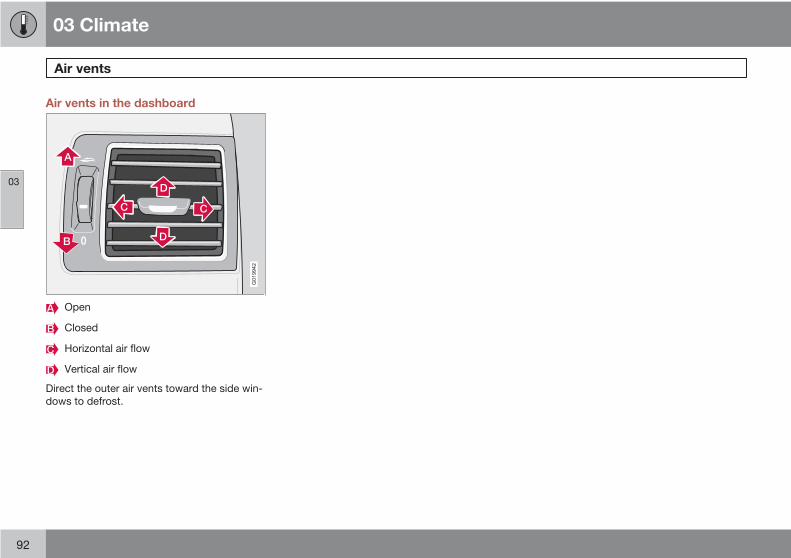
03 Climate
Air vents
03
92
Air vents in the dashboard
G019942
Open
Closed
Horizontal air flow
Vertical air flow
Direct the outer air vents toward the side win-dows to defrost.

03 Climate
Manual climate control
03
93
G019515
Climate system control panel
Blower speed
Recirculation
Defroster
Airflow controls
A/C – ON/OFF
Heated driver's seat
Heated front passenger's seat
Rear window and door mirror defrosters
Temperature selector
Manual climate system functions
1. BlowerThe blower speed can beincreased or decreased byturning the knob. If the knob isturned counterclockwise andthe indicator light in the dis-play goes out, the blower andthe air conditioning are
switched off. The display shows the blowersymbol and OFF.
2. RecirculationThis function can be used toshut out exhaust fumes,smoke, etc from the passen-ger compartment. The air inthe passenger compartmentis then recirculated, i.e. no airfrom outside the car is taken
into the car when this function is activated.Recirculation (together with the air condition-ing system) cools the passenger compartmentmore quickly in very warm weather. If the air inthe car recirculates for too long, there is a riskof condensation forming on the insides of thewindows, especially in winter.
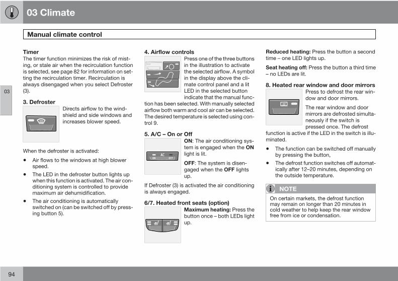
03 Climate
Manual climate control
03
94
TimerThe timer function minimizes the risk of mist-ing, or stale air when the recirculation functionis selected, see page 82 for information on set-ting the recirculation timer. Recirculation isalways disengaged when you select Defroster(3).
3. DefrosterDirects airflow to the wind-shield and side windows andincreases blower speed.
When the defroster is activated:
• Air flows to the windows at high blowerspeed.
• The LED in the defroster button lights upwhen this function is activated. The air con-ditioning system is controlled to providemaximum air dehumidification.
• The air conditioning is automaticallyswitched on (can be switched off by press-ing button 5).
4. Airflow controlsPress one of the three buttonsin the illustration to activatethe selected airflow. A symbolin the display above the cli-mate control panel and a litLED in the selected buttonindicate that the manual func-
tion has been selected. With manually selectedairflow both warm and cool air can be selected.The desired temperature is selected using con-trol 9.
5. A/C – On or OffON: The air conditioning sys-tem is engaged when the ONlight is lit.
OFF: The system is disen-gaged when the OFF lightsup.
If Defroster (3) is activated the air conditioningis always engaged.
6/7. Heated front seats (option)Maximum heating: Press thebutton once – both LEDs lightup.
Reduced heating: Press the button a secondtime – one LED lights up.
Seat heating off: Press the button a third time– no LEDs are lit.
8. Heated rear window and door mirrorsPress to defrost the rear win-dow and door mirrors.
The rear window and doormirrors are defrosted simulta-neously if the switch ispressed once. The defrost
function is active if the LED in the switch is illu-minated.
• The function can be switched off manuallyby pressing the button,
• The defrost function switches off automat-ically after 12–20 minutes, depending onthe outside temperature.
NOTE
On certain markets, the defrost functionmay remain on longer than 20 minutes incold weather to help keep the rear windowfree from ice or condensation.

03 Climate
Manual climate control
03
95
9. Temperature selectorThe knob with the thermome-ter symbol is used to selectcooling or heating for both thedriver's and passenger'ssides of the car.

03 Climate
Electronic Climate Control (ECC) – option
03
96
G019518
Auto – On/Off
Blower speed
Recirculation
Defroster
Airflow controls
A/C – ON/OFF
Heated driver's seat
Heated front passenger's seat
Rear window and door mirror defrosters
Temperature selector
ECC functions
1. Auto – On/OffThe AUTO function automat-ically regulates climate con-trol to maintain the desiredtemperature. The automaticfunction controls heating, airconditioning, blower speed,recirculation, and air distribu-
tion.
If you select one or more manual functions, theremaining functions continue to be controlledautomatically. All manual settings are switchedoff when AUTO is switched on. AUTOCLIMATE is shown in the display.
2. Blower speedThe blower speed can beincreased or decreased byturning the knob. The blowerspeed is regulated automati-cally if AUTO is selected. Thepreviously set blower speed isdisconnected.
NOTE
If the knob is turned counterclockwise andthe blower indication in the display goesout, the blower and the air conditioning areswitched off. The display shows the blowersymbol and OFF.

03 Climate
Electronic Climate Control (ECC) – option
03
97
3. RecirculationThis function can be used toshut out exhaust fumes,smoke, etc from the passen-ger compartment. The air inthe passenger compartmentis then recirculated, i.e. no airfrom outside the car is taken
into the car when this function is activated.
If the air in the car recirculates for too long,there is a risk of condensation forming on theinsides of the windows, especially in winter.
TimerThe timer function minimizes the risk of foggingor stale air when the recirculation function isselected, see page 82 for information on set-ting the recirculation timer.
NOTE
Recirculation is always disengaged if thedefroster button is engaged to clear ice orcondensation from the side windows.
4. DefrosterDirects airflow to the wind-shield and side windows andincreases blower speed.When the defroster is acti-vated:
• Air flows to the windows at high blowerspeed.
• The LED in the defroster button lights upwhen this function is activated. The air con-ditioning system is controlled to providemaximum air dehumidification.
• The air conditioning is automaticallyswitched on (can be switched off by press-ing button 6).
The air is not recirculated.
5. Airflow controlsPress one of the three buttonsin the illustration to activatethe selected airflow. A symbolin the display above the cli-mate control panel and a litLED in the selected buttonindicate that the manual func-
tion has been selected. With manually selectedairflow both warm and cool air can be selected.See also the table on page 97.
6. Air conditioning On/OffON: The air conditioning sys-tem is engaged when the ONlight is lit and is controlledautomatically by the systemto maintain the selected tem-perature.
OFF: The system is disengaged when theOFF lights up
When OFF is selected and the OFF LED is lit,the air conditioning system is deactivated.Other functions are still controlled automati-cally.
When Defroster (4) is selected, the air condi-tioning system is activated for maximum dehu-midifying.
7 and 8. Heated front seats (option)Maximum heating: Press thebutton once – both LEDs lightup.
Reduced heating: Press thebutton a second time – oneLED lights up.
Seat heating off: Press the button a third time– no LEDs are lit.

03 Climate
Electronic Climate Control (ECC) – option
03
98
9. Rear window and door mirrordefrosters
Press to defrost the rear win-dow and door mirrors.
The rear window and doormirrors are defrosted simulta-neously if the switch ispressed once. The defrost
function is active if the LED in the switch is illu-minated.
• The function can be switched off manuallyby pressing the button.
• The defrost function switches off automat-ically after 12–20 minutes, depending onthe outside temperature.
NOTE
• On certain markets, the defrost functionmay remain on longer than 20 minutesin cold weather to help keep the rearwindow free from ice or condensation.
10. Temperature selectorThe temperatures on the driv-er's and passenger's sidescan be set separately usingthe knob (with the thermome-ter in it). The temperature canbe set for both sides of the carwhen the ignition is switched
on (both LEDs will be on), which means that atemperature setting will apply to both sides ofthe car.
To set the temperature on one side of the car:
1. Press the knob once. The LED for one sideof the car will light up. Turn the knob toadjust the temperature.
2. Press the knob a second time to set thetemperature on the opposite side of thecar.
3. Press the knob a third time to set the tem-perature on both sides of the car at thesame time.
NOTE
Selecting a temperature that is higher orlower than necessary will not heat or coolthe passenger compartment faster.
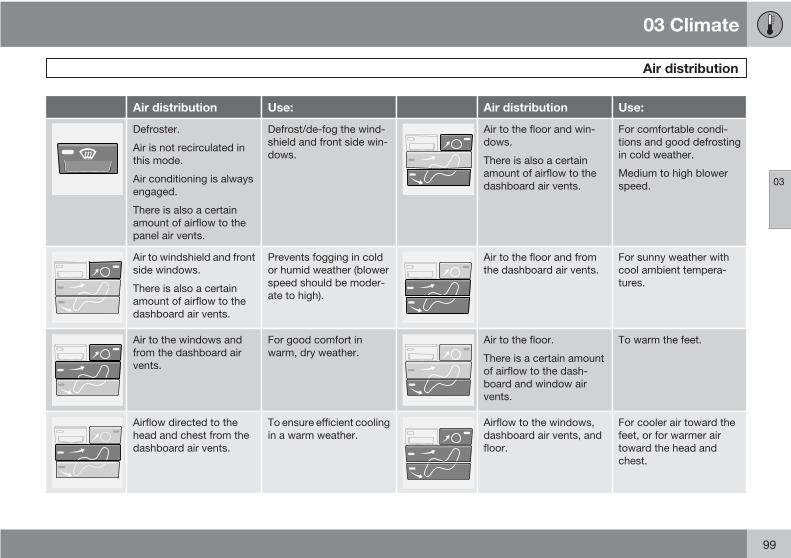
03 Climate
Air distribution
03
99
Air distribution Use: Air distribution Use:
Defroster.
Air is not recirculated inthis mode.
Air conditioning is alwaysengaged.
There is also a certainamount of airflow to thepanel air vents.
Defrost/de-fog the wind-shield and front side win-dows.
Air to the floor and win-dows.
There is also a certainamount of airflow to thedashboard air vents.
For comfortable condi-tions and good defrostingin cold weather.
Medium to high blowerspeed.
Air to windshield and frontside windows.
There is also a certainamount of airflow to thedashboard air vents.
Prevents fogging in coldor humid weather (blowerspeed should be moder-ate to high).
Air to the floor and fromthe dashboard air vents.
For sunny weather withcool ambient tempera-tures.
Air to the windows andfrom the dashboard airvents.
For good comfort inwarm, dry weather.
Air to the floor.
There is a certain amountof airflow to the dash-board and window airvents.
To warm the feet.
Airflow directed to thehead and chest from thedashboard air vents.
To ensure efficient coolingin a warm weather.
Airflow to the windows,dashboard air vents, andfloor.
For cooler air toward thefeet, or for warmer airtoward the head andchest.

G020908
100
Front seats............................................................................................ 102Interior lighting...................................................................................... 105Storage compartments......................................................................... 107Rear seat............................................................................................... 111Cargo area............................................................................................ 113

04INTERIOR

04 Interior
Front seats
04
102
Manual seat adjustment
G027960
The driver's and passenger's seats can beadjusted in a number of ways to provide acomfortable driving and sitting position.
Forward-rearward: Pull the lever up andslide the seat to the position of your choice.
Use this control to raise or lower the frontedge of the seat cushion.
Use this control to raise or lower the rearedge of the seat cushion.
Turn this knob (option on some passeng-er's seats) to adjust the firmness of thelumbar support1.
Turn this knob to adjust the backrest tilt.
Control panel for power seats.
WARNING
• Do not adjust the seat while driving.
• Adjust the driver’s seat and seat belt(see page 18) before driving. The seatshould be adjusted so that the brakepedal can be depressed fully.
• Position the seat as far rearward ascomfort and control allow.
Folding down the front seat backrests
G014805
The front passenger's seat backrest can befolded down to provide room for long loads.
1. Move the seat as far back as possible.
2. Adjust the backrest to the upright position.
3. Lift the catches on the rear of the backrestas shown in the illustration.
4. Without releasing the catches, push thebackrest forward.
5. Move the seat as far forward as possibleso that the head restraint slides under theglove compartment.
1 Also applies to the optional power seat.

04 Interior
Front seats
04
103
WARNING
Cover sharp edges on the load to help pre-vent injury to occupants. Secure the load tohelp prevent shifting during sudden stops.
Power seats (option)The power driver's seat can be adjusted:
• If the ignition key is in position I or II.
• During a 10 minute period after the doorshave been unlocked if the door remainsopen.
• If the door is closed and the ignition key isnot yet in the ignition, or if the key is inposition 0, the seat can be adjusted or dur-ing a period of 40 seconds. The powerpassenger's seat can only be adjusted ifthe ignition key is in position I or II, or if theengine is running.
Adjusting the seat
G020199
Seat adjustment controls
Seat adjustment controls 1, 2, 3, and 4 on theside of the seat can be used to move the seatto the position of your choice.
Move this section of the control up or downto raise/lower the front section of the seatcushion.
Move the control forward/rearward tomove the seat forward or rearward.
Move this section of the control up or downto raise/lower the rear section of the seatcushion.
Backrest tilt.
NOTE
The power seats have an overload protectorthat activates if a seat is blocked by anyobject. If this occurs, switch off the ignition(key in position 0) and wait for approxi-mately 20 seconds before operating theseat again.
Emergency stopIf the seat inadvertently begins to move, pressany of the buttons to stop the seat.
Programming the seat memory, driver'sseat only (option)
G020200
Power seat memory buttons

04 Interior
Front seats
04
104
Three different seating positions can be storedin the seat's memory. The memory buttons arelocated on the outboard side of the driver'sseat (see the illustration above). The followingexample explains how memory button 1 can beprogrammed. Buttons 2 and 3 can be pro-grammed in the same way.
To program (store) a seat position in memorybutton 1:
1. Adjust the seat to the desired position.
2. Press and hold down the "M" (Memory)button.
3. With the "M" button depressed, pressmemory button 1 to store the seat's currentposition.
To move the seat to the position that it was inwhen memory button 1 was programmed,press and hold down button 1 until the seatstops moving.
As a safety precaution, the seat will stop auto-matically if the button is released before theseat has reached the preset position.
Central locking system remote controland driver's seat memoryThe remote control transmitter can also beequipped with an optional function that con-trols the electrically operated driver's seat inthe following way:
1. Adjust the seat to the desired position.
2. When you leave the car, lock it using theremote control.
3. The next time the driver's door is unlockedwith the same remote control and that dooris opened within 2 minutes, the driver'sseat and side door mirrors will automati-cally move to the position that they were inwhen the doors were most recently lockedwith the same remote control.
NOTE
The memory function in the remote controloperates independently the memory func-tion in the seat.
WARNING
• Because the driver's seat can beadjusted with the ignition off, childrenshould never be left unattended in thecar.
• Movement of the seat can be STOPPEDat any time by pressing any button onthe power seat control panel.
• Do not adjust the seat while driving. Theseat should be adjusted so that thebrake pedal can be depressed fully. Inaddition, position the seat as far rear-ward as comfort and control allow.
• The seat rails on the floor must not beobstructed in any way when the seat isin motion.
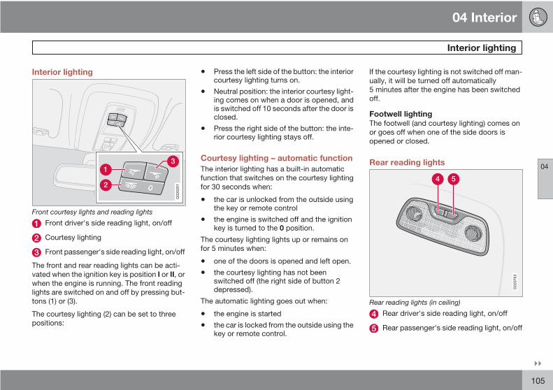
04 Interior
Interior lighting
04
105
Interior lighting
G020201
Front courtesy lights and reading lights
Front driver's side reading light, on/off
Courtesy lighting
Front passenger's side reading light, on/off
The front and rear reading lights can be acti-vated when the ignition key is position I or II, orwhen the engine is running. The front readinglights are switched on and off by pressing but-tons (1) or (3).
The courtesy lighting (2) can be set to threepositions:
• Press the left side of the button: the interiorcourtesy lighting turns on.
• Neutral position: the interior courtesy light-ing comes on when a door is opened, andis switched off 10 seconds after the door isclosed.
• Press the right side of the button: the inte-rior courtesy lighting stays off.
Courtesy lighting – automatic functionThe interior lighting has a built-in automaticfunction that switches on the courtesy lightingfor 30 seconds when:
• the car is unlocked from the outside usingthe key or remote control
• the engine is switched off and the ignitionkey is turned to the 0 position.
The courtesy lighting lights up or remains onfor 5 minutes when:
• one of the doors is opened and left open.
• the courtesy lighting has not beenswitched off (the right side of button 2depressed).
The automatic lighting goes out when:
• the engine is started
• the car is locked from the outside using thekey or remote control.
If the courtesy lighting is not switched off man-ually, it will be turned off automatically5 minutes after the engine has been switchedoff.
Footwell lightingThe footwell (and courtesy lighting) comes onor goes off when one of the side doors isopened or closed.
Rear reading lights
G020763
Rear reading lights (in ceiling)
Rear driver's side reading light, on/off
Rear passenger's side reading light, on/off

04 Interior
Interior lighting
04
106
The rear reading lights can be switched on oroff by pressing the respective buttons, andfunction if the ignition key is in positions I, II, orif the engine is running.
The courtesy lighting can be switched on or offwithin 30 minutes after the engine has beenswitched off, or after a door has been openedor closed.
These lights switch off automatically 5 minutesafter the engine has been switched off.
Vanity mirrorG020210
Raise the cover to switch on the light.

04 Interior
Storage compartments
04
107
G02
6508

04 Interior
Storage compartments
04
108
Storage pocket (on the rear side of the frontseats)
Compartment in door panel
Storage pocket (on the front side of thefront seat cushion)
Glove compartment
Storage compartment for e.g., CDs andcup holders
Jacket hanger (intended for light garmentsonly)
Rear seat storage compartment and cupholders
Storage pocket (on the front side of therear, center seat cushion).
WARNING
• Anchor any heavy objects to preventthem from moving during sudden stops.
• Packages on the rear parcel shelf canobscure vision and may become dan-gerous projectiles in the event of a sud-den stop or an accident.
Glove compartment
G024208
The owners manual and maps can be storedhere. There are also holders for coins, pens andfuel cards. The glove compartment can only belocked and unlocked using the detachable keyblade from the central locking system's remotecontrol. See page 120 for information onremoving the key blade from the remote con-trol, and page 127 for information about lock-ing the glove compartment.
Jacket hanger
G018137
The jacket hanger is located on the inboardside of the front passenger's seat headrestraint. It is only intended for hanging lightgarments.
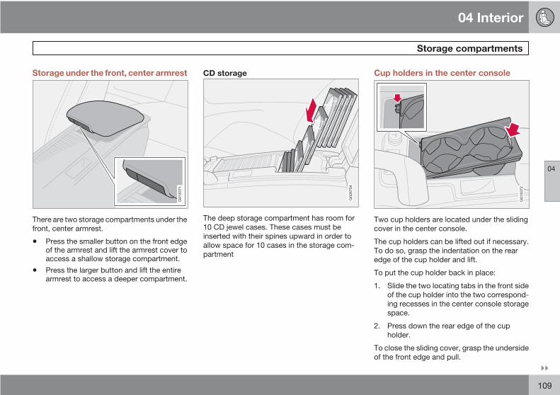
04 Interior
Storage compartments
04
109
Storage under the front, center armrest
G018371
There are two storage compartments under thefront, center armrest.
• Press the smaller button on the front edgeof the armrest and lift the armrest cover toaccess a shallow storage compartment.
• Press the larger button and lift the entirearmrest to access a deeper compartment.
CD storage
G026704
The deep storage compartment has room for10 CD jewel cases. These cases must beinserted with their spines upward in order toallow space for 10 cases in the storage com-partment
Cup holders in the center console
G018372
Two cup holders are located under the slidingcover in the center console.
The cup holders can be lifted out if necessary.To do so, grasp the indentation on the rearedge of the cup holder and lift.
To put the cup holder back in place:
1. Slide the two locating tabs in the front sideof the cup holder into the two correspond-ing recesses in the center console storagespace.
2. Press down the rear edge of the cupholder.
To close the sliding cover, grasp the undersideof the front edge and pull.

04 Interior
Storage compartments
04
110
Storage compartment behind the gearlever
G019623
If the buttons for optional equipment are notinstalled, the recess behind the gear lever canbe used as a storage compartment for coins,etc.
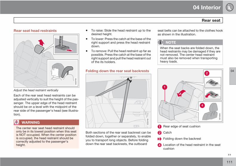
04 Interior
Rear seat
04
111
Rear seat head restraints
G020765
Adjust the head restraint vertically
Each of the rear seat head restraints can beadjusted vertically to suit the height of the pas-senger. The upper edge of the head restraintshould be on a level with the midpoint of therear side of the passenger's head (see illustra-tion).
WARNING
The center rear seat head restraint shouldonly be in its lowest position when this seatis NOT occupied. When the center positionis occupied, the head restraint should becorrectly adjusted to the passenger’sheight.
• To raise: Slide the head restraint up to thedesired height.
• To lower: Press the catch at the base of theright support and press the head restraintdown.
• To remove: Pull the head restraint up far aspossible. Press the catch at the base of theright support and pull the head restraint outof the its holders.
Folding down the rear seat backrests
G020790
Both sections of the rear seat backrest can befolded down, together or separately, to enableyou to transport long objects. Before foldingdown the rear seat backrests, the outboard
seat belts can be attached to the clothes hookas shown in the illustration.
NOTE
When the seat backs are folded down, thehead restraints may be damaged if they arenot removed. The center head restraintmust also be removed when transportingheavy loads.
G014845
Rear edge of seat cushion
Catch
Folding down the backrest
Location of the head restraint in the seatcushion

04 Interior
Rear seat
04
112
To fold down one or both sections:
1. Grasp the rear edge of the seat cushionand pull it forward.
2. Pull the catch on the upper outboard edgeof the backrest upward and forward torelease the backrest lock. A red lock indi-cator is visible when the backrest is notlocked in the upright position.
3. Fold the backrest down partially andremove the outboard head restraints.Press the center head restraint down com-pletely or remove it.
4. Place the head restraints in the plastictubes, which are now accessible on theunder side of the seat cushions.
NOTE
When folding down the rear seat backrests,remove the plug in the rear 12 volt socket tohelp avoid marks in the upholstery.
WARNING
• The red lock indicator is VISIBLE whenthe backrest is NOT locked in positionand hidden when the backrest is cor-rectly locked in place. When the back-rest is in the upright position, it mustalways be correctly locked in place.
• When the rear seat is folded down, donot place heavy objects against thebacks of the front seats. This places asevere strain on the folded down back-rest of the rear seat. Be sure to securecargo.
• Cargo must not be stacked higher thanthe top of seat backs. This will reducethe possibility of luggage, etc. becom-ing projectiles during sudden maneu-vers, rapid braking or an accident.
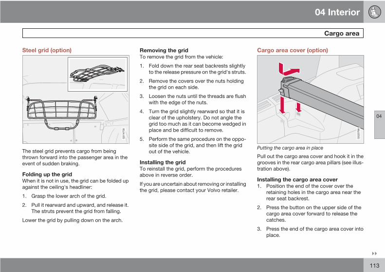
04 Interior
Cargo area
04
113
Steel grid (option)
G014730
The steel grid prevents cargo from beingthrown forward into the passenger area in theevent of sudden braking.
Folding up the gridWhen it is not in use, the grid can be folded upagainst the ceiling's headliner:
1. Grasp the lower arch of the grid.
2. Pull it rearward and upward, and release it.The struts prevent the grid from falling.
Lower the grid by pulling down on the arch.
Removing the gridTo remove the grid from the vehicle:
1. Fold down the rear seat backrests slightlyto the release pressure on the grid's struts.
2. Remove the covers over the nuts holdingthe grid on each side.
3. Loosen the nuts until the threads are flushwith the edge of the nuts.
4. Turn the grid slightly rearward so that it isclear of the upholstery. Do not angle thegrid too much as it can become wedged inplace and be difficult to remove.
5. Perform the same procedure on the oppo-site side of the grid, and then lift the gridout of the vehicle.
Installing the gridTo reinstall the grid, perform the proceduresabove in reverse order.
If you are uncertain about removing or installingthe grid, please contact your Volvo retailer.
Cargo area cover (option)
G020766
Putting the cargo area in place
Pull out the cargo area cover and hook it in thegrooves in the rear cargo area pillars (see illus-tration above).
Installing the cargo area cover1. Position the end of the cover over the
retaining holes in the cargo area near therear seat backrest.
2. Press the button on the upper side of thecargo area cover forward to release thecatches.
3. Press the end of the cargo area cover intoplace.

04 Interior
Cargo area
04
114
4. Release the button to lock the cargo areacover in place.
5. Repeat this procedure on the opposite sideof the cargo area.
Check that the cargo area cover is securely inplace.
G020767
Fold the front section of the cover forward
Fold the front section of the cargo area coverforward into the wedge-shaped grooves nearthe rear seat.
Removing the cargo area cover1. Lift the forward section of the cover, fold it
rearward in the vehicle, and let it hangfreely.
2. Press the button on the upper edge of thecover forward to release the catches.
3. Lift out the end of the cargo area coverfrom the retaining holes.
4. Repeat the procedure on the opposite sideof the cargo area.
NOTE
Both versions of the cargo area cover areoptions that may be available for your vehi-cle. Consult your Volvo retailer.
Cargo area net (accessory)
G020768
The Volvo V50 can be equipped with a cargoarea net made of strong nylon fabric that canbe used with the rear seat backrests in theupright position or folded down.
The holder for the retractable net is mountedon the rear side of the backrests.
Using the net with the backrests in theupright position1. From the cargo compartment, pull the net
upward.
2. Insert the net's right attachment in the rear-most hole in the mounting bracket (seeillustration) and push it forward into thesmaller hole in the bracket to secure it inplace.
3. Pull out the spring-loaded attachment onthe left side of the net and insert it in thebracket on the left side of the vehicle in thesame way.
WARNING
Be sure that the net is securely attached inthe mounting brackets.
Using the cargo net with the backrestfolded downFasten the net in the same way as describedabove, using the front mounting brackets.

04 Interior
Cargo area
04
115
Retracting the cargo net1. Pull back one of the net's attachments to
the large hole in the mounting bracket.
2. Pull the attachment out of the mountingbracket.
3. Do the same on the opposite side of thevehicle.
4. Lower the net into its holder.
Removing the cargo net's holder1. Fold down the backrests
2. Push the holder out until it releases from itsretaining brackets.
Using the net with the cargo area cover
G020769
1. Fold the rear seat backrests forwardslightly. Begin by folding the narrower sec-tion of the backrest.
2. Pull the cargo net up and to the rear.
3. Return the backrests to the upright posi-tion.
Insert the net's end attachments into themounting brackets (see the illustration).
WARNING
The red lock indicator on the rear seatbackrests is VISIBLE when the backrest isNOT locked in position and hidden when thebackrest is correctly locked in place. Whenthe backrest is in the upright position, itmust always be correctly locked in place.
Load anchoring eyelets
G014757
The eyelets in the cargo area can be used tofasten accessory load and lashing straps, loadnets, and other load anchors.
116
Remote control and key blade.............................................................. 118Keyless drive (option as available)........................................................ 123Locking and unlocking.......................................................................... 127Child safety locks.................................................................................. 129Alarm (option)........................................................................................ 130
05LOCKS AND ALARM

05 Locks and alarm
Remote control and key blade
05
118
Remote controlsTwo remote controls that also function as igni-tion keys are provided with your car. Theremote controls contain detachable metal keyblades for manually locking or unlocking thedriver's door and the glove compartment.
USA – FCC ID: LTQVO315TX
This device complies with part 15 of the FCCrules. Operation is subject to the following con-ditions: (1) This device may not cause harmfulinterference, and (2) this device must acceptany interference received, including interfer-ence that may cause undesired operation.
Canada – IC: 3659AVO315TX
Operation is subject to the following condi-tions: (1) this device may not cause interfer-ence, and (2) this device must accept anyinterference, including interference that maycause undesired operation of the device.
Loss of a remote controlIf either of the remote controls is lost, the othermust be taken with the car to a Volvo retailer.As an anti-theft measure, the code of the lostremote control must be erased from the sys-tem.
Each key blade has a unique code, which isused if new key blades are required. A maxi-
mum of six remote controls/key blades can beprogrammed and used for one car.
Immobilizer (start inhibitor)Each of the keys supplied with your car con-tains a coded transponder. The code in the keyis transmitted to an antenna in the ignitionswitch where it is compared to the code storedin the start inhibitor module. The car will startonly with a properly coded key. If you misplacea key, take the other keys to an authorizedVolvo retailer for reprogramming as an antitheftmeasure.
USA – FCC ID: LTQWFS 125VO
This device complies with part 15 of the FCCrules. Operation is subject to the following con-dition: (1) This device may not cause harmfulinterference, and (2) this device must acceptany interference received, including interfer-ence that may cause undesired operation.
Canada – IC: 3659A-WFS125VO
Operation is subject to the following condi-tions: (1) this device may not cause interfer-ence, and (2) this device must accept anyinterference, including interference that maycause undesired operation of the device.
CAUTION
Never use force on the narrow section of theremote control – this is where the trans-ponder is located. The car cannot be startedif the transponder is damaged.
Remote control functions
G019402
Lock – Press the Lock button on theremote once to lock all doors and the tail-gate. The turn signals will flash once toconfirm locking.

05 Locks and alarm
Remote control and key blade
05
119
NOTE
The car can also be locked if a door is open(does not apply to vehicles with the optionalkeyless drive).
Unlock – Press the Unlock button on theremote once to unlock the driver's door.After a short pause, press the Unlock but-ton a second time within 10 seconds tounlock the other doors and the tailgate. Along press (at least two seconds) opens allside windows.
NOTE
• The turn signals flash to confirm that thevehicle has been correctly locked/unlocked with the remote control or theoptional keyless drive. When locking thevehicle, the turn signals will flash a con-firmation only if all the doors aresecurely closed and locked. Flashingconfirmation for locking and unlockingmay be customized in the vehicle's Per-sonal settings menu, see page 82 formore information.
• The two-step unlocking function can bechanged so that one press of theUnlock button unlocks all of the doorsand the tailgate. See Personal settingspage 82 for more information.
• Automatic relocking: If the doors areunlocked, the locks will automatically reen-gage (re-lock) and the alarm will rearm after2 minutes unless a door or the tailgate hasbeen opened.
• Automatic locking: When the car starts tomove, the doors and tailgate can be lockedautomatically. This feature can be turnedon or off, see Personal settings on page82 for more information.
• Airbag deployment will automaticallyattempt to unlock the doors.
Approach lighting – As you approach thecar: Press the button on the remote controlto illuminate the area around the car in darkconditions. Pressing the button once lightsup the interior lighting, parking lights, andlicense plate lighting. These lights willswitch off automatically after 30, 60 or90 seconds. See the Personal settings page 82 for information about adjusting thetime setting.
Unlock tailgate – Press the button once todisarm the alarm system and unlock onlythe tailgate. After closing, the tailgate willnot automatically relock. Press Lock torelock it and rearm the alarm.
NOTE
This function will not open the tailgate.
Panic alarm – This button can be used toattract attention during emergency situa-tions. To activate the panic alarm, pressand hold the red button for at least 3 sec-onds or press it twice within 3 seconds.The turn signals and horn will be activated.The panic alarm will stop automaticallyafter 30 seconds. To deactivate, waitapproximately 5 seconds and press the redbutton again.

05 Locks and alarm
Remote control and key blade
05
120
NOTE
This button will NOT unlock the car.
Weak battery in the remote control
G019406
When the battery begins to lose its charge, theInformation symbol in the instrument panel(see page 53) lights up and KEY BATTERYLOW VOLTAGE is shown in the informationdisplay.
Replacing the battery in the remotecontrolIf the range of the transmitter is noticeablyreduced, this indicates that the battery (typeCR 2450, 3V) is weak and should be replaced.To replace the battery:
1. Place the remote control with the keypaddownward. Pry open the cover with a smallslotted screwdriver.
2. Remove the cover.
CAUTION
When replacing the battery, avoid touchingthe electrical circuitry in the other half of theremote control.
3. Note how the + and – sides of the batteryare positioned on the inside of the cover(see the underside of the cover).
4. Pry out and replace the battery. Avoidtouching the battery and its contact surfa-ces with your fingers.
5. Press the cover back into place.
The old battery should be disposed of properlyat a recycling center or by a trained and quali-fied Volvo service technician.
Key blade
G019403
Removing the key blade
The key blade can be removed from the remotecontrol. When removed, it can be used as fol-lows:
• To lock/unlock the driver’s door
• To lock/unlock the glove compartment,see page 127
Removing the key bladeSlide the spring loaded catch to the side.
While holding the catch, pull the key bladeout of the remote control.
05 Locks and alarm
Remote control and key blade
05
121
Reinserting the key blade in the remotecontrol1. Hold the remote control with the pointed
end down.
2. Carefully slide the key blade into its groove.
3. Gently press the key blade in the grooveuntil it clicks into place.
Unlocking the doors with the detachedkey blade
Insert the key blade as far as possible in thedriver's door lock. Turn the key bladeclockwise approximately one-quarter turnto unlock the driver's door only.
NOTE
After unlocking the driver's door with thekey blade, opening the door will trigger thealarm.
To disable the alarmPress the Unlock button on the remote control,or insert the key in the ignition switch.
Locking the doors with the detached keyblade1. Lock the other door(s) by pressing the lock
button on each door. Please note that thisdoes not arm the alarm or lock the tailgate.
2. Turn the key blade one-quarter turn coun-ter-clockwise to lock the driver's door.

05 Locks and alarm
Remote control and key blade
05
122
Locking points
G019450
Locking/unlocking points for the remotecontrol with the key blade
Locking/unlocking points for the remotecontrol without the key blade
By utilizing the remote control with the keyblade removed, you can block access to theglove compartment for e.g. valet parking orwhen the car is brought to the retailer for serv-ice.

05 Locks and alarm
Keyless drive (option as available)
05
123
Keyless locking and unlocking
G019451
Range of the keyless drive remote control–5 ft(1.5 meters)
This system makes it possible to unlock andlock the vehicle without having to use theremote control. It is only necessary to have akeyless drive remote control in your posses-sion to operate the central locking system.
NOTE
The buttons on the keyless drive remotecontrol can also be used to lock and unlockthe vehicle, see page 118 for more informa-tion.
Both of the remote controls provided with thevehicle have the keyless function, and addi-tional remotes can be ordered. The system canaccommodate up to six keyless drive remotecontrols.
NOTE
The number of doors that are unlocked atthe same time can be set in the Personalsettings menu, see page 82 for additionalinformation.
Unlocking the vehicle• A keyless drive remote control must be on
the same side of the vehicle as the door tobe opened, and be within 5 feet(1.5 meters) of the lock or the tailgate open-ing control (see the shaded areas in theillustration).
• Pull a door handle to unlock and open thedoor or press the tailgate opening controlon the tailgate.
• See page 146 for information on starting avehicle equipped with keyless drive.
Locking the vehicle
G020033
Keyless drive lock button
The doors and the tailgate can be locked bypressing the lock button in any of the outsidedoor handles.
NOTE
• If one or more doors and/or the tailgateis not fully closed when the lock buttonis pressed, the door(s) or tailgate will notbe locked.
• On keyless drive vehicles with an auto-matic transmission, the gear selectormust be in the Park (P) position and theignition must be switched off before thedoors/tailgate can be locked.
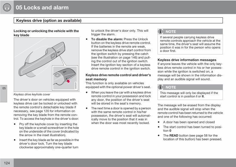
05 Locks and alarm
Keyless drive (option as available)
05
124
Locking or unlocking the vehicle with thekey blade
G020225
Keyless drive keyhole cover
The driver's door on vehicles equipped withkeyless drive can be locked or unlocked withthe remote control's detachable key blade ifnecessary, see page 120 for information onremoving the key blade from the remote con-trol. To access the keyhole in the driver's door:
• Pry off the keyhole cover by inserting thekey blade or a small screwdriver in the holeon the underside of the cover (indicated bythe arrow in the inset illustration).
• Insert the key blade as far as possible in thedriver's door lock. Turn the key bladeclockwise approximately one-quarter turn
to unlock the driver's door only. This willtrigger the alarm.
• To disable the alarm: Press the Unlockbutton on the keyless drive remote control.If the batteries in the remote are weak,remove the keyless drive start control fromthe ignition switch by pressing the catch(see the illustration on page 146) and pull-ing the control out of the ignition switch.Insert the ignition key section of a keylessdrive remote control in the ignition switch.
Keyless drive remote control and driver'sseat memoryThis function is only available on vehiclesequipped with the optional power driver's seat.
• When you leave the car with a keyless driveremote control in your possession and lockany door, the position of the driver's seatwill be stored in the seat's memory.
• The next time a door is opened by a personwith the same remote control in his/herpossession, the driver's seat will automat-ically move to the position that it was inwhen the door was most recently locked.
NOTE
If several people carrying keyless driveremote controls approach the vehicle at thesame time, the driver's seat will assume theposition it was in for the person who opensa door first.
Keyless drive information messagesIf anyone leaves the vehicle with the only key-less drive remote control in his or her posses-sion while the ignition is switched on, amessage will be shown in the information dis-play and an audible signal will sound.
NOTE
This message will only be displayed if thestart control is in position I or II.
The message will be erased from the displayand the audible signal will stop when theremote control has been returned to the vehicleand one of the following has occurred:
• A door has been opened and closed
• The start control has been turned to posi-tion 0
• The READ button (see page 58 for thelocation of this button) has been pressed.
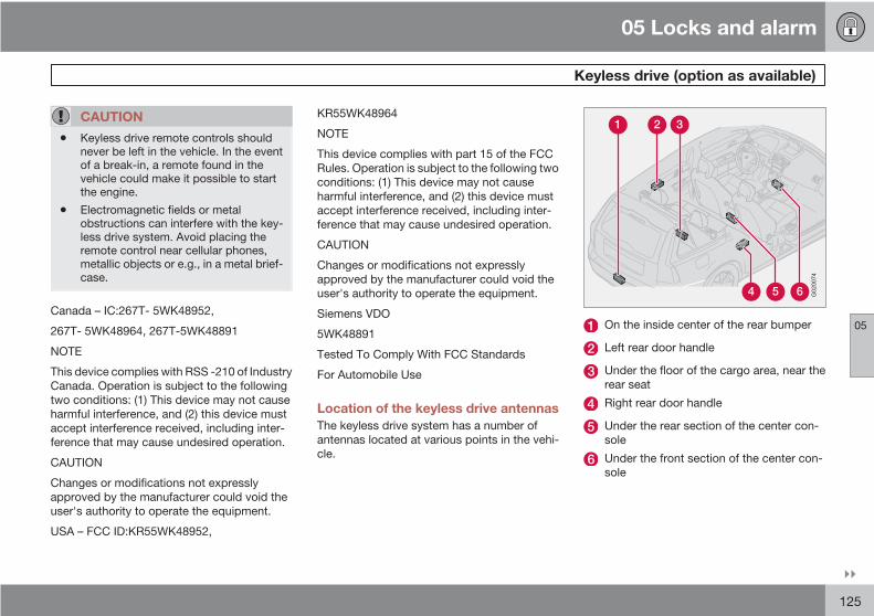
05 Locks and alarm
Keyless drive (option as available)
05
125
CAUTION
• Keyless drive remote controls shouldnever be left in the vehicle. In the eventof a break-in, a remote found in thevehicle could make it possible to startthe engine.
• Electromagnetic fields or metalobstructions can interfere with the key-less drive system. Avoid placing theremote control near cellular phones,metallic objects or e.g., in a metal brief-case.
Canada – IC:267T- 5WK48952,
267T- 5WK48964, 267T-5WK48891
NOTE
This device complies with RSS -210 of IndustryCanada. Operation is subject to the followingtwo conditions: (1) This device may not causeharmful interference, and (2) this device mustaccept interference received, including inter-ference that may cause undesired operation.
CAUTION
Changes or modifications not expresslyapproved by the manufacturer could void theuser's authority to operate the equipment.
USA – FCC ID:KR55WK48952,
KR55WK48964
NOTE
This device complies with part 15 of the FCCRules. Operation is subject to the following twoconditions: (1) This device may not causeharmful interference, and (2) this device mustaccept interference received, including inter-ference that may cause undesired operation.
CAUTION
Changes or modifications not expresslyapproved by the manufacturer could void theuser's authority to operate the equipment.
Siemens VDO
5WK48891
Tested To Comply With FCC Standards
For Automobile Use
Location of the keyless drive antennasThe keyless drive system has a number ofantennas located at various points in the vehi-cle.
G020074
On the inside center of the rear bumper
Left rear door handle
Under the floor of the cargo area, near therear seat
Right rear door handle
Under the rear section of the center con-sole
Under the front section of the center con-sole

05 Locks and alarm
Keyless drive (option as available)
05
126
WARNING
People with implanted pacemakers shouldnot allow the pacemaker to come closerthan 9 inches (22 cm) to any of the keylessdrive system's antennas. This is to help pre-vent interference between the pacemakerand the keylesss drive system.

05 Locks and alarm
Locking and unlocking
05
127
Locking/unlocking the vehicle from theinside
G007451
The switches near the door opening handles onthe driver's and front passenger's doors can beused to lock or unlock all doors and the tail-gate, open the side windows1, and to set thealarm.
• Unlocking: Press the upper section of theswitch. A long press (for several seconds)also opens all the side windows.
• Locking: Press the lower section of thelock button.
NOTE
• The ignition key must be in position I orhigher (see page 143) before all sidewindows can be opened using theswitches in the front doors.
• The doors cannot be opened by pullingup the lock buttons.
• Each door can also be locked manuallyusing the lock button on that particulardoor. This applies only if the car has notbeen locked from the outside.
• The doors can also be unlocked (andthe door opened) by pulling the handlein the door twice.
Locking the glove compartment
G020034
The glove compartment can only be lockedand unlocked using the detachable key bladeon the remote control, see page 120 for infor-mation on removing the key blade from theremote control.
Insert the key blade in the glove compart-ment lock.
Turn the key blade 90 degrees clockwise.The key slot will be in the horizontal posi-tion.
Remove the key blade from the lock.
1 This function must be set to On in the Personal settings menu (see page 83)

05 Locks and alarm
Locking and unlocking
05
128
Unlock the glove compartment in the reverseorder.
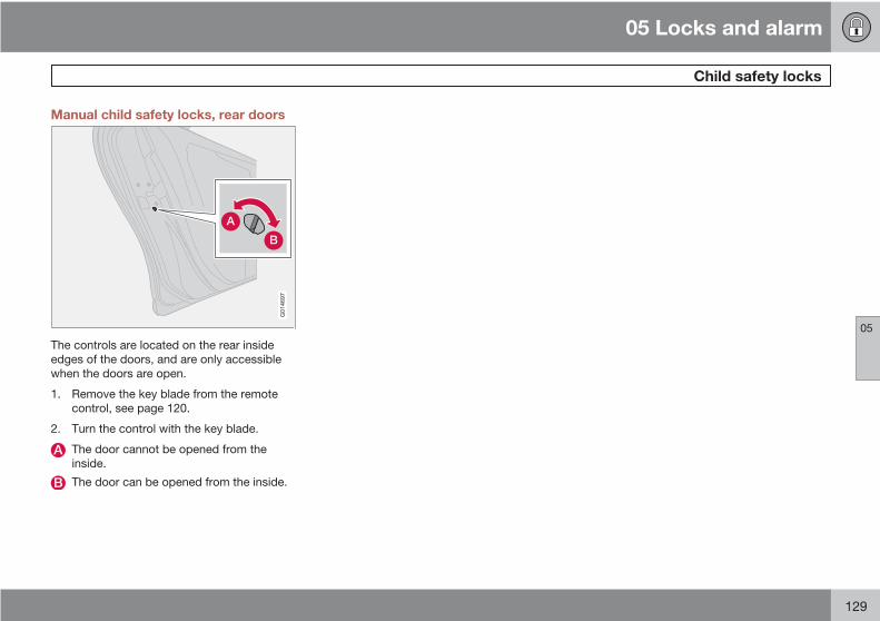
05 Locks and alarm
Child safety locks
05
129
Manual child safety locks, rear doors
G014697
The controls are located on the rear insideedges of the doors, and are only accessiblewhen the doors are open.
1. Remove the key blade from the remotecontrol, see page 120.
2. Turn the control with the key blade.
The door cannot be opened from theinside.
The door can be opened from the inside.

05 Locks and alarm
Alarm (option)
05
130
The alarm systemThe alarm is automatically armed whenever thecar is locked with the remote control, or if afront lock button is depressed.
When armed, the alarm continuously monitorsa number of points on the car. The followingconditions will trigger the alarm:
• The hood is forced open.
• The tailgate is forced open.
• A door is forced open.
• The ignition switch is tampered with
• An attempt is made to start the car with anon-approved key (a key not coded to thecar's ignition).
• If there is movement in the passenger com-partment (if the car is equipped with theoptional movement sensor).
• The car is lifted or towed (if the car is equip-ped with the optional inclination sensor)
• The battery is disconnected (while thealarm is armed).
• The siren is disconnected when the alarmis disarmed.
The alarm indicator light
G020227
Alarm indicator light
The status of the alarm system is indicated bythe indicator light on at the top of the dash-board (see the illustration):
• Indicator light off – the alarm is not armed
• The indicator light flashes every two sec-onds – the alarm is armed
• The indicator light flashes rapidly beforethe ignition is switched on – the alarm hasbeen triggered. The message "ALARMTRIGGERED, CHECK CAR" will also bedisplayed.
• Fault in the alarm system: If a fault hasbeen detected in the alarm system, a mes-sage will be shown in the information dis-play. Contact your Volvo retailer to havethe alarm system inspected and repaired ifnecessary.
Arming the alarmPress the LOCK button on the remote control,or press the central lock button on one of thefront doors with the door open. One long flashof the turn signals will confirm that the alarm isarmed.
Disarming the alarmPress the UNLOCK button on the remote con-trol or insert the key in the ignition1 to disarmthe alarm. Two short flashes from the car'sdirection indicators confirm that the alarm hasbeen deactivated and that all doors areunlocked.
1 On vehicles with the optional keyless drive, press in the start control in the ignition switch.
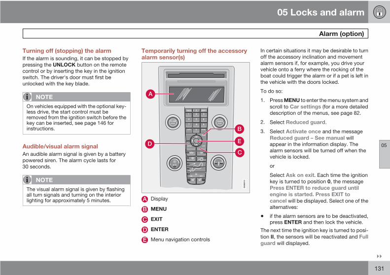
05 Locks and alarm
Alarm (option)
05
131
Turning off (stopping) the alarmIf the alarm is sounding, it can be stopped bypressing the UNLOCK button on the remotecontrol or by inserting the key in the ignitionswitch. The driver's door must first beunlocked with the key blade.
NOTE
On vehicles equipped with the optional key-less drive, the start control must beremoved from the ignition switch before thekey can be inserted, see page 146 forinstructions.
Audible/visual alarm signalAn audible alarm signal is given by a batterypowered siren. The alarm cycle lasts for30 seconds.
NOTE
The visual alarm signal is given by flashingall turn signals and turning on the interiorlighting for approximately 5 minutes.
Temporarily turning off the accessoryalarm sensor(s)
G02
6313
Display
MENU
EXIT
ENTER
Menu navigation controls
In certain situations it may be desirable to turnoff the accessory inclination and movementalarm sensors if, for example, you drive yourvehicle onto a ferry where the rocking of theboat could trigger the alarm or if a pet is left inthe vehicle with the doors locked.
To do so:
1. Press MENU to enter the menu system andscroll to Car settings (for a more detaileddescription of the menus, see page 82.
2. Select Reduced guard.
3. Select Activate once and the messageReduced guard – See manual willappear in the information display. Thealarm sensors will be turned off when thevehicle is locked.
or
Select Ask on exit. Each time the ignitionkey is turned to position 0, the messagePress ENTER to reduce guard untilengine is started. Press EXIT tocancel will be displayed. Select one of thealternatives:
• if the alarm sensors are to be deactivated,press ENTER and then lock the vehicle.
The next time the ignition key is turned to posi-tion II, the sensors will be reactivated and Fullguard will displayed.
05 Locks and alarm
Alarm (option)
05
132
or
If you do not wish to deactivate the sensors, donot choose an alternative and lock the vehicleor press EXIT and lock the vehicle.
CAUTION
• The accessory sensors are automati-cally reconnected to the alarm systemthe next time the vehicle is unlockedand then locked again.
• This function will not turn off the vehi-cle's standard alarm.
U.S.A. FCC ID: MAYDA 5823(3)
This device complies with part 15 of the FCCrules. Operation is subject to the following con-ditions: (1) This device may not cause harmfulinterference, and (2) this device must acceptany interference received, including interfer-ence that may cause undesired operation.
Canada IC: 4405A-DA 5823(3)
Movement sensor DA5823 by Dynex Operationis subject to the following conditions: (1) thisdevice may not cause interference, and (2) thisdevice must accept any interference, includinginterference that may cause undesired opera-tion of the device.
05 Locks and alarm
05
133

G020912
134
General information............................................................................... 136Fuel requirements................................................................................. 140Ignition switch....................................................................................... 143Starting the vehicle............................................................................... 144Starting the vehicle with keyless drive (option as available)................. 146Manual transmission, 5-speed (certain markets only).......................... 147Manual transmission, 6-speed (certain markets only).......................... 148Automatic transmission (option)........................................................... 149Shiftlock override.................................................................................. 151All Wheel Drive (option)......................................................................... 152Brake system........................................................................................ 153Stability system..................................................................................... 155Towing................................................................................................... 157Jump starting........................................................................................ 159Towing a trailer...................................................................................... 160Detachable trailer hitch......................................................................... 162Transporting loads................................................................................ 163Blind Spot Information System (BLIS)–option...................................... 164Park assist (Option/accessory)............................................................. 168

06STARTING AND DRIVING

06 Starting and driving
General information
06
136
Economical driving conserves naturalresourcesBetter driving economy may be obtained bythinking ahead, avoiding rapid starts and stopsand adjusting the speed of your vehicle toimmediate traffic conditions.
Observe the following rules:
• Bring the engine to normal operating tem-perature as soon as possible by drivingwith a light foot on the accelerator pedal forthe first few minutes of operation. A coldengine uses more fuel and is subject toincreased wear.
• Whenever possible, avoid using the vehiclefor driving short distances. This does notallow the engine to reach normal operatingtemperature.
• Drive carefully and avoid rapid accelerationand hard braking.
• Use the transmission's Drive (D) positionas often as possible and avoid using kick-down.
• Do not exceed posted speed limits.
• Avoid carrying unnecessary items (extraload) in the vehicle.
• Maintain correct tire pressure. Check tirepressure regularly (when tires are cold).
• Remove snow tires when threat of snow orice has ended.
• Note that roof racks, ski racks, etc,increase air resistance and also fuel con-sumption.
• At highway driving speeds, fuel consump-tion will be lower with the air conditioningon and the windows closed than with theair conditioning off and the windows open.
• Using the onboard trip computer's fuelconsumption modes can help you learnhow to drive more economically.
Other factors that decrease gas mileageare:• Dirty air cleaner
• Dirty engine oil and clogged oil filter
• Dragging brakes
• Incorrect front end alignment
Some of the above mentioned items and othersare checked at the standard maintenanceintervals.
WARNING
Driving with the tailgate open: Driving withthe tailgate open could lead to poisonousexhaust gases entering the passenger com-partment. If the tailgate must be kept openfor any reason, proceed as follows:
1. Close the windows.
2. Set the ventilation system control to airflow to floor, windshield and side win-dows and the blower control to its high-est setting.
Weight distribution affects handlingAt the specified curb weight your vehicle has atendency to understeer, which means that thesteering wheel has to be turned more thanmight seem appropriate for the curvature of abend. This ensures good stability and reducesthe risk of rear wheel skid. Remember thatthese properties can alter with the vehicle load.The heavier the load in the cargo area, the lessthe tendency to understeer.
06 Starting and driving
General information
06
137
Handling, roadholdingVehicle load, tire design and inflation pressureall affect vehicle handling. Therefore, checkthat the tires are inflated to the recommendedpressure according to the vehicle load. See the"Tire pressure" section. Loads should be dis-tributed so that capacity weight or maximumpermissible axle loads are not exceeded.
Driving through waterThe vehicle can be driven through water up toa depth of approximately 9 in. (25 cm), at amaximum speed of 6 mph (10 km/h).
• Take particular care when driving throughflowing water.
• Clean the electrical connections for trailerwiring after driving in mud or water
• When driving through water, maintain lowspeed and do not stop in the water.
WARNING
After driving through water, press lightly onthe brake pedal to ensure that the brakesare functioning normally. Water or mud canmake the brake linings slippery, resulting indelayed braking effect.
CAUTION
• Engine damage will occur if water isdrawn into the air cleaner.
• If the vehicle is driven through waterdeeper than 9 in (25 cm), water mayenter the differential and the transmis-sion. This reduces the oil's lubricatingcapacity and may shorten the servicelife of these components.
• Do not allow the vehicle to stand inwater up to the door sills longer thanabsolutely necessary. This could resultin electrical malfunctions.
• If the engine has been stopped while thecar is in water, do not attempt to restartthe engine. Have the car towed out ofthe water.
Cold weather precautionsIf you wish to check your vehicle before theapproach of cold weather, the following adviceis worth noting:
• Make sure that the engine coolant contains50 percent antifreeze. Any other mixturewill reduce freeze protection. This givesprotection against freezing down to –31 °F(–35 °C). See section "Coolant". The use of"recycled" antifreeze is not approved by
Volvo. Different types of antifreeze mustnot be mixed.
• Volvo recommends using only genuineVolvo antifreeze in your vehicle's radiator.Your Volvo retailer stocks plenty of Volvoengine coolant to help protect your vehicleduring cold weather.
• Try to keep the fuel tank well filled – thisprevents the formation of condensation inthe tank. In addition, in extremely coldweather conditions it is worthwhile to addfuel line de-icer before refueling.
• The viscosity of the engine oil is important.Oil with low viscosity (thinner oil) improvescold-weather starting as well as decreas-ing fuel consumption while the engine iswarming up. For winter use, 5W-30 oil, par-ticularly the synthetic type1, is recom-mended. Be sure to use good quality oil butdo not use cold-weather oil for hard drivingor in warm weather, see page 269 for moreinformation.
• The load placed on the battery is greaterduring the winter since the windshield wip-ers, lighting, etc. are used more often.Moreover, the capacity of the batterydecreases as the temperature drops. Invery cold weather, a poorly charged bat-tery can freeze and be damaged. It is there-fore advisable to check the state of charge
1 Synthetic oil is not used when the oil is changed at the normal maintenance intervals except at owner request and at additional charge. Please consult your Volvo retailer.

06 Starting and driving
General information
06
138
more frequently and spray an anti-rust oilon the battery posts.
• Volvo recommends the use of snow tireson all four wheels for winter driving – seethe chapter "Wheels and tires."
• To prevent the washer fluid reservoir fromfreezing, add washer solvents containingantifreeze (see page 215 for the location ofthe washer fluid reservoir). This is impor-tant since dirt is often splashed on thewindshield during winter driving, requiringthe frequent use of the washers and wip-ers. Volvo Washer Solvent should be dilu-ted as follows: Down to 14 °F (–10 °C): 1part washer solvent and 4 parts waterDown to 5° F (–15° C): 1 part washer sol-vent and 3 parts water Down to 0° F(–18° C): 1 part washer solvent and 2 partswater Down to –18° F (–28° C): 1 partwasher solvent and 1 part water.
• Use Volvo Teflon Lock Spray in the locks.
NOTE
Avoid using de-icing sprays as they cancause damage to the locks.
Conserving electrical currentKeep the following in mind to help minimizebattery drain:
• When the engine is not running, avoid turn-ing the ignition key to position II. Manyelectrical systems (the audio system, theoptional navigation system, power win-dows, etc) will function with the ignition keyin position I. This position reduces drain onthe battery.
• Please keep in mind that using systems,accessories, etc that consume a great dealof current when the engine is not runningcould result in the battery being completelydrained.
• The optional 12 volt socket in the cargoarea (certain models only) provides electri-cal current even with the ignition switchedoff, which drains the battery.
NOTE
• If the ignition is switched on, a warningmessage will be displayed in the textwindow in the instrument panel whenthe battery charge is low.
• An energy conserving functiondesigned into the vehicle's electricalsystem will switch off certain functionsor reduce the load on the battery by,e.g., reducing the audio system's vol-ume.
Before a long distance tripIt is always worthwhile to have your vehiclechecked at a trained and qualified Volvo serv-ice technician before driving long distances.Your trained and qualified Volvo service tech-nician will also be able to supply you withbulbs, fuses, spark plugs and wiper blades foryour use in the event that problems occur.
As a minimum, the following items should bechecked before any long trip:
• Check that engine runs smoothly and thatfuel consumption is normal.
• Check for fuel, oil, and fluid leakage
• Have the transmission oil level checked2.
• Check condition of drive belts.
2 To prevent injury from contact with hot surfaces, do not inspect your vehicle's transmission fluid yourself. Have your vehicle's transmission fluid level inspected by a qualified Volvo service technician.
06 Starting and driving
General information
06
139
• Check state of the battery's charge.
• Examine tires carefully (the spare tire aswell), and replace those that are worn.Check tire pressures.
• The brakes, front wheel alignment, andsteering gear should be checked by yourVolvo retailer only.
• Check all lights, including high beams.
• Reflective warning triangles are legallyrequired in some states/provinces.
• Have a word with your Volvo retailer if youintend to drive in countries where it may bedifficult to obtain the correct fuel.
• Consider your destination. If you will bedriving through an area where snow or iceare likely to occur, consider snow tires.

06 Starting and driving
Fuel requirements
06
140
Octane rating
Minimum octane
G02
8920
Typical pump octane label
Volvo recommends premium fuel for best per-formance, but using 87 octane or above will notaffect engine reliability.
Volvo engines are designed to achieve ratedhorsepower, torque, and fuel economy per-formance using premium 91 octane fuel.
Demanding drivingIn demanding driving conditions, such as oper-ating the vehicle in hot weather, towing a trailer,or driving for extended periods at higher alti-tudes than normal, it may be advisable toswitch to higher octane fuel (91 or higher) or tochange gasoline brands to fully utilize your
engine's capacity, and for the smoothest pos-sible operation.
NOTE
When switching to higher octane fuel orchanging gasoline brands, it may be neces-sary to fill the tank more than once before adifference in engine operation is noticeable.
Fuel FormulationsDo not use gasoline that contains lead as aknock inhibitor, and do not use lead additives.Besides damaging the exhaust emission con-trol systems on your vehicle, lead has beenstrongly linked to certain forms of cancer.
Many fuels contain benzene as a solvent.Unburned benzene has been strongly linked tocertain forms of cancer. If you live in an areawhere you must fill your own gas tank, takeprecautions. These may include:
• standing upwind away from the filler nozzlewhile refueling
• refueling only at gas stations with vaporrecovery systems that fully seal the mouthof the filler neck during refueling
• wearing neoprene gloves while handling afuel filler nozzle.
Use of AdditivesWith the exception of gas line antifreeze duringwinter months, do not add solvents, thicken-ers, or other store-bought additives to yourvehicle's fuel, cooling, or lubricating systems.Overuse may damage your engine, and someof these additives contain organically volatilechemicals. Do not needlessly expose yourselfto these chemicals.
WARNING
Never carry a cell phone that is switchedon while refueling your vehicle. If the phonerings, this may cause a spark that couldignite gasoline fumes, resulting in fire andinjury.
WARNING
Carbon monoxide is a poisonous, colorless,and odorless gas. It is present in all exhaustgases. If you ever smell exhaust fumesinside the vehicle, make sure the passengercompartment is ventilated, and immediatelyreturn the vehicle to a trained and qualifiedVolvo service technician for correction.

06 Starting and driving
Fuel requirements
06
141
Deposit control gasoline (detergentadditives)Volvo recommends the use of detergent gas-oline to control engine deposits. Detergentgasoline is effective in keeping injectors andintake valves clean. Consistent use of depositcontrol gasolines will help ensure good driva-bility and fuel economy. If you are not surewhether the gasoline contains deposit controladditives, check with the service station oper-ator.
NOTE
Volvo does not recommend the use ofstore-bought fuel injector cleaning addi-tives.
Unleaded fuelEach Volvo has a three-way catalytic converterand must use only unleaded gasoline. U.S. andCanadian regulations require that pumps deliv-ering unleaded gasoline be labelled "UNLEA-DED". Only these pumps have nozzles whichfit your vehicle's filler inlet. It is unlawful to dis-pense leaded fuel into a vehicle labelled"unleaded gasoline only". Leaded gasolinedamages the three-way catalytic converter andthe heated oxygen sensor system. Repeateduse of leaded gasoline will lessen the effec-
tiveness of the emission control system andcould result in loss of emission warranty cov-erage. State and local vehicle inspection pro-grams will make detection of misfueling easier,possibly resulting in emission test failure formisfueled vehicles.
NOTE
Some U.S. and Canadian gasolines containan octane enhancing additive called methyl-cyclopentadienyl manganese tricarbonyl(MMT). If such fuels are used, your EmissionControl System performance may be affec-ted, and the Check Engine Light (malfunc-tion indicator lamp) located on your instru-ment panel may light. If this occurs, pleasereturn your vehicle to a trained and qualifiedVolvo service technician for maintenance.
Gasoline containing alcohol and ethersSome fuel suppliers sell gasoline containing"oxygenates" which are usually alcohols orethers. In some areas, state or local lawsrequire that the service pump be marked indi-cating use of alcohols or ethers. However,there are areas in which the pumps areunmarked. If you are not sure whether there isalcohol or ethers in the gasoline you buy, checkwith the service station operator. To meet sea-sonal air quality standards, some areas requirethe use of "oxygenated" fuel. Volvo allows the
use of the following "oxygenated" fuels; how-ever, the octane ratings listed on this pagemust still be met. Alcohol – Ethanol: Fuelscontaining up to 10% ethanol by volume maybe used. Ethanol may also be referred to asEthyl alcohol, or "Gasohol". Ethers – MTBE:Fuels containing up to 15% MTBE may beused.
Fuel filler doorPress the button on the light switch panel (seethe illustration on page 61) with the ignitionswitched off to unlock the fuel filler door.Please note that the fuel filler door will remainunlocked until the vehicle begins to move for-ward. An audible click will be heard when thefuel filler door relocks.
If you intend to leave your vehicle while it isbeing refueled, this feature enables you to lockthe doors/tailgate while leaving the fuel fillerdoor unlocked.
You can also keep the vehicle locked if youremain inside it during refueling. The centrallocking button does not lock the fuel filler door.
Be sure the fuel filler door is not obstructed andis completely closed after refueling. Open thefuel filler cap slowly during hot weather.

06 Starting and driving
Fuel requirements
06
142
RefuelingThe fuel tank is designed to accommodatepossible expansion of the fuel in hot weather,see page 267 for fuel tank volume. Be awarethat the "usable" tank capacity will be some-what less than the specified maximum. Whenthe fuel level is low, such factors as ambienttemperature, the fuel's "Reid vapor pressure"characteristics, and terrain can affect the fuelpump's ability to supply the engine with anadequate supply of fuel. Therefore, it is advis-able to refuel as soon as possible when theneedle nears the red zone, or when the fuelwarning light comes on.
CAUTION
• Do not refuel with the engine running1.Turn the ignition off or to position I. If theignition is on, an incorrect reading couldoccur in the fuel gauge
• After refueling, close the fuel filler capby turning it clockwise until it clicks intoplace.
• Avoid overfilling the fuel tank. Do notpress the handle on the filler nozzlemore than one extra time. Too muchfuel in the tank in hot weather conditionscan cause the fuel to overflow. Overfill-ing could also cause damage to theemission control systems.
• Avoid spilling gasoline during refueling.In addition to causing damage to theenvironment, gasolines containingalcohol can cause damage to paintedsurfaces, which may not be coveredunder the New Vehicle Limited War-ranty.
• Do not use gasolines containing meth-anol (methyl alcohol, wood alcohol).This practice can result in vehicle per-formance deterioration and can dam-age critical parts in the fuel system.Such damage may not be covered
under the New Vehicle Limited War-ranty.
1 If the fuel filler cap is not closed tightly or if the engine is running when the vehicle is refueled, the Check Engine Light (malfunction indicator lamp) may indicate a fault. However, your vehicle’sperformance will not be affected. Use only Volvo original or approved fuel filler caps.
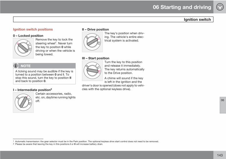
06 Starting and driving
Ignition switch
06
143
Ignition switch positions
0 – Locked positionRemove the key to lock thesteering wheel1. Never turnthe key to position 0 whiledriving or when the vehicle isbeing towed.
NOTE
A ticking sound may be audible if the key isturned to a position between 0 and I. Tostop this sound, turn the key to position IIand back to position 0.
I – Intermediate position2
Certain accessories, radio,etc. on, daytime running lightsoff.
II – Drive positionThe key's position when driv-ing. The vehicle's entire elec-trical system is activated.
III – Start positionTurn the key to this positionand release it immediately.The key returns automaticallyto the Drive position.
A chime will sound if the keyis left in the ignition and the
driver's door is opened (does not apply to vehi-cles with the optional keyless drive).
1 Automatic transmission: the gear selector must be in the Park position. The optional keyless drive start control does not need to be removed.2 Please be aware that leaving the key in this positions I or II will increase battery drain.

06 Starting and driving
Starting the vehicle
06
144
To start the engine
WARNING
Before starting, check that the seat, steeringwheel and mirrors are adjusted properly.Make sure the brake pedal can bedepressed completely. Adjust the seat ifnecessary.
1. Fasten the seat belt.
2. Apply the parking brake if not already set.The gear selector should be locked in thePark (P) position (Shiftlock). See also page151.
Manual transmission: The clutch must befully depressed.
NOTE
After a cold start, idle speed may be notice-ably higher than normal for a short period.This is done to help bring components in theemission control system to their normaloperating temperature as quickly as possi-ble, which enables them to control emis-sions and help reduce the vehicle's impacton the environment.
3. The vehicle is equipped with an autostartfeature. Without touching the throttle
pedal, turn the key to position III andrelease it. The starter motor will then oper-ate automatically (for up to ten seconds)until the engine starts. If the engine fails tostart, repeat this step.
4. To release the gear selector from the Park(P) position, the engine must be running (orthe ignition key must be in position II) andthe brake pedal must be depressed.
5. Select the desired gear. On models with anautomatic transmission, the gear engagesafter a very slight delay which is especiallynoticeable when selecting R.
NOTE
• Immobilizer: If two of the keys to yourvehicle are close together, e.g., on thesame key ring when you try to start thevehicle, this could cause interference inthe immobilizer system and result in thevehicle not starting. If this should occur,remove one of the keys from the keyring before trying to start the vehicleagain.
• Keylock: Models equipped an auto-matic transmission have a keylock sys-tem. When the engine is switched off,the gear selector must be in the Park(P) position before the key can beremoved from the ignition switch1.
• When starting in cold weather, thetransmission may shift up at slightlyhigher engine speeds than normal untilthe automatic transmission fluid rea-ches normal operating temperature.
• Do not race a cold engine immediatelyafter starting. Oil flow may not reachsome lubrication points fast enough toprevent engine damage.
1 The optional keyless drive start control does not need to be removed from the ignition switch.

06 Starting and driving
Starting the vehicle
06
145
WARNING
Volvo's floor mats are specially manufac-tured for your car. They must be firmlysecured in the clips on the floor so that theycannot slide and become trapped under thepedals on the driver's side.
• Always place the gear selector in Park(P) (manual transmission: first or reversegear) and apply the parking brakebefore leaving the vehicle.and apply theparking brake before leaving the vehi-cle. Never leave the vehicle unattendedwith the engine running.
• Always open garage doors fully beforestarting the engine inside a garage toensure adequate ventilation. Theexhaust gases contain carbon monox-ide, which is invisible and odorless butvery poisonous.
CAUTION
Automatic transmission: The engineshould be idling when you move the gearselector. Never accelerate until after youfeel the transmission engage! Acceleratingimmediately after selecting a gear will causeharsh engagement and premature trans-mission wear. Selecting P or N when idlingat a standstill for prolonged periods of timewill help prevent overheating of the auto-matic transmission fluid.
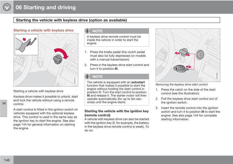
06 Starting and driving
Starting the vehicle with keyless drive (option as available)
06
146
Starting a vehicle with keyless drive
G019410
Starting a vehicle with keyless drive
Keyless drive makes it possible to unlock, startand lock the vehicle without using a remotecontrol.
A start control is fitted in the ignition switch onvehicles equipped with the optional keylessdrive. This control is used in the same way asthe ignition key to start the engine. See alsopage 144 for general information on startingthe engine.
NOTE
A keyless drive remote control must beinside the vehicle in order to start theengine.
1. Press the brake pedal (the clutch pedalmust also be fully depressed on modelswith a manual transmission).
2. Press in the keyless drive start control andturn it to position III.
NOTE
The vehicle is equipped with an autostartfunction that makes it possible to start theengine without holding the start control inposition III. Turn the start control to positionIII and release it. The starter motor will thenoperate automatically (for up to ten sec-onds) until the engine starts.
Starting the vehicle with the ignition key(remote control)A vehicle with keyless drive can also be startedwith the ignition key (if, for example, the batteryin the keyless drive remote control is weak). Todo so:
G019420
Removing the keyless drive start control
1. Press the catch on the side of the startcontrol (see the illustration).
2. Pull the keyless drive start control out ofthe ignition switch.
3. Insert the remote control into the ignitionswitch and turn it to position III to start theengine. See also page 144 for completestarting information.

06 Starting and driving
Manual transmission, 5-speed (certain markets only)
06
147
5-speed manual transmission (optionon certain models)
G018256
Depress the clutch pedal completely whenchanging gears1.
Remove your foot from the clutch pedal whiledriving. The shift pattern should be followed.
Overdrive (5th gear) should be used as often aspossible to help improve fuel economy.
Engaging reverse gear, 5-speedtransmission
G018257
Reverse gear should only be engaged from acomplete stop.
NOTE
Reverse gear is electronically blocked tohelp prevent it from being selected while thevehicle is moving foward.
CAUTION
Never shift into reverse while moving for-ward.
WARNING
An extra mat on the driver's floor can causethe accelerator, brake, and/or clutch pedalto catch. Check that the movement of thesepedals is not impeded. Not more than oneprotective floor covering may be used atone time.
1 Clutch interlock: The clutch must be fully depressed before you can start your car. If the clutch is not depressed, it will not be possible to start the engine.
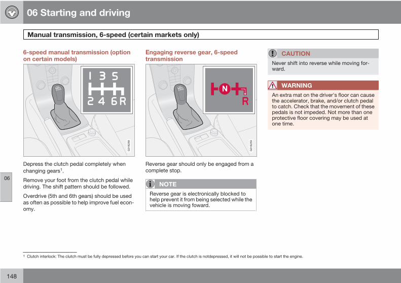
06 Starting and driving
Manual transmission, 6-speed (certain markets only)
06
148
6-speed manual transmission (optionon certain models)
G018258
Depress the clutch pedal completely whenchanging gears1.
Remove your foot from the clutch pedal whiledriving. The shift pattern should be followed.
Overdrive (5th and 6th gears) should be usedas often as possible to help improve fuel econ-omy.
Engaging reverse gear, 6-speedtransmission
G018259
Reverse gear should only be engaged from acomplete stop.
NOTE
Reverse gear is electronically blocked tohelp prevent it from being selected while thevehicle is moving foward.
CAUTION
Never shift into reverse while moving for-ward.
WARNING
An extra mat on the driver's floor can causethe accelerator, brake, and/or clutch pedalto catch. Check that the movement of thesepedals is not impeded. Not more than oneprotective floor covering may be used atone time.
1 Clutch interlock: The clutch must be fully depressed before you can start your car. If the clutch is notdepressed, it will not be possible to start the engine.
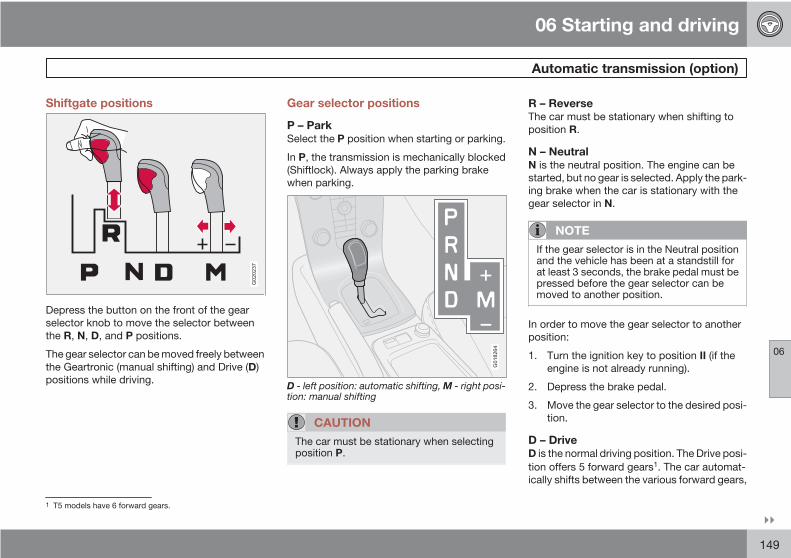
06 Starting and driving
Automatic transmission (option)
06
149
Shiftgate positions
G020237
Depress the button on the front of the gearselector knob to move the selector betweenthe R, N, D, and P positions.
The gear selector can be moved freely betweenthe Geartronic (manual shifting) and Drive (D)positions while driving.
Gear selector positions
P – ParkSelect the P position when starting or parking.
In P, the transmission is mechanically blocked(Shiftlock). Always apply the parking brakewhen parking.
G018264
D - left position: automatic shifting, M - right posi-tion: manual shifting
CAUTION
The car must be stationary when selectingposition P.
R – ReverseThe car must be stationary when shifting toposition R.
N – NeutralN is the neutral position. The engine can bestarted, but no gear is selected. Apply the park-ing brake when the car is stationary with thegear selector in N.
NOTE
If the gear selector is in the Neutral positionand the vehicle has been at a standstill forat least 3 seconds, the brake pedal must bepressed before the gear selector can bemoved to another position.
In order to move the gear selector to anotherposition:
1. Turn the ignition key to position II (if theengine is not already running).
2. Depress the brake pedal.
3. Move the gear selector to the desired posi-tion.
D – DriveD is the normal driving position. The Drive posi-tion offers 5 forward gears1. The car automat-ically shifts between the various forward gears,
1 T5 models have 6 forward gears.

06 Starting and driving
Automatic transmission (option)
06
150
based on the level of acceleration and speed.The car must be at a standstill when shifting toposition D from position R.
Manual shifting – GeartronicThe manual shifting mode (Geartronic) can beselected at any time to manually select forwardgears, including while the car is moving.
NOTE
Reverse, Neutral, and Park cannot beselected in Geartronic mode.
• To access the Manual (M) shifting positionfrom Drive (D), move the gear selector tothe right to M.
• To return to the Drive (D) position from M,move the gear selector to the left.
While driving• If you select the M position while driving,
the gear that was being used in the Driveposition will also initially be selected in theM position.
• Move the gear selector forward (toward"+") to shift to a higher gear or rearward(toward "–") to shift to a lower gear.
• If you hold the gear selector toward "–", thetransmission will downshift one gear at atime and will utilize the braking power of
the engine. If the current speed is too highfor using a lower gear, the downshift willnot occur until the speed has decreasedenough to allow the lower gear to be used.
• If you slow to a very low speed, the trans-mission will automatically shift down.
Cold starts (turbo engines)When driving before the engine has reached itsnormal operating temperature, the transmis-sion will shift up at slightly higher enginespeeds to heat the three-way catalytic con-verter as quickly as possible.
KickdownAutomatic shift to a lower gear (kickdown) isachieved by depressing the accelerator pedalfully and briskly. An upshift will occur whenapproaching the top speed for a particular gearor by releasing the accelerator pedal slightly.Kickdown can be used for maximum acceler-ation or when passing at highway speeds.
Safety functionTo help prevent excessive engine speeds (rpm)that could lead to engine damage, the enginemanagement system includes a function thatprevents kickdown from taking place if theengine speed is too high.
Kickdown will not occur if the driver attemptsto use this function when engine speeds aretoo high. The transmission will remain in thecurrently selected gear.
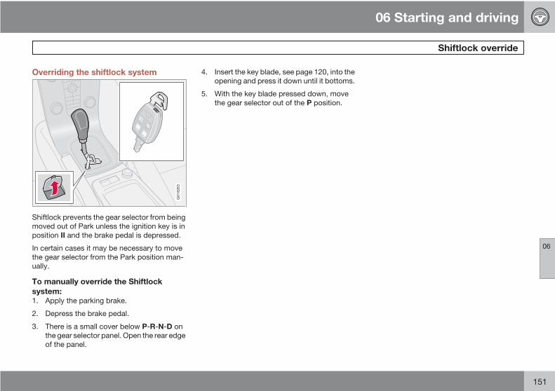
06 Starting and driving
Shiftlock override
06
151
Overriding the shiftlock system
G018263
Shiftlock prevents the gear selector from beingmoved out of Park unless the ignition key is inposition II and the brake pedal is depressed.
In certain cases it may be necessary to movethe gear selector from the Park position man-ually.
To manually override the Shiftlocksystem:1. Apply the parking brake.
2. Depress the brake pedal.
3. There is a small cover below P-R-N-D onthe gear selector panel. Open the rear edgeof the panel.
4. Insert the key blade, see page 120, into theopening and press it down until it bottoms.
5. With the key blade pressed down, movethe gear selector out of the P position.
06 Starting and driving
All Wheel Drive (option)
06
152
All Wheel Drive (AWD) – generalinformationYour Volvo can be equipped with permanentAll Wheel Drive (option), which means thatpower is distributed automatically between thefront and rear wheels. Under normal drivingconditions, most of the engine's power isdirected to the front wheels. However, if thereis any tendency for the front wheels to spin, anelectronically controlled coupling distributespower to the wheels that have the best traction.
Tire dimensionsVolvo recommends that you always drive ontires of the same brand, size, construction(radial), tread pattern, load, speed, traction,temperature, and treadwear rating. Never driveon mixed tires, except for brief periods whenthe temporary spare tire is in use.
Always use properly inflated tires of correctdimensions. Tire size and inflation pressuresare shown on a placard located on the driver'sside B-pillar (the structural member at the sideof the vehicle, at the rear of the driver's dooropening). See also page 178 for the tire infla-tion pressure tables beginning, .
Temporary SpareThe temporary spare tire is for temporary, low-speed, short-distance use only. Replace it witha full-sized tire as soon as possible. Do notdrive on the temporary spare at speeds above50 mph (80 km/h).
Never install snow chains on a temporaryspare.
06 Starting and driving
Brake system
06
153
Brake circuit malfunctionThe brake system is a hydraulic system con-sisting of two separate brake circuits. If a prob-lem should occur in one of these circuits, it isstill possible to stop the vehicle with the otherbrake circuit.
If the brake pedal must be depressed fartherthan normal and requires greater foot pressure,the stopping distance will be longer.
A warning light in the instrument panel will lightup to warn the driver that a fault has occurred.
If this light comes on while driving or braking,stop immediately and check the brake fluidlevel in the reservoir.
NOTE
Press the brake pedal hard and maintainpressure on the pedal – do not pump thebrakes.
WARNING
If the fluid level is below the MIN mark in thereservoir or if a brake system message isshown in the information display, DO NOTDRIVE. Have the vehicle towed to a Volvoretailer and have the brake system inspec-ted.
Power brakes function only when theengine is runningThe power brakes utilize vacuum pressurewhich is only created when the engine is run-ning. Never let the vehicle roll to a stop with theengine switched off.
If the power brakes are not working, the brakepedal must be pressed approximately fivetimes harder than usual to make up for the lackof power assistance. This can happen forexample when towing your vehicle or if theengine is switched off when the vehicle is roll-ing. The brake pedal feels harder than usual.
Water on brake discs and brake padsaffects brakingDriving in rain and slush or passing through anautomatic car wash can cause water to collecton the brake discs and pads. This will cause adelay in braking effect when the pedal isdepressed. To avoid such a delay when thebrakes are needed, depress the pedal occa-sionally when driving through rain, slush, etc.This will remove the water from the brakes.Check that brake application feels normal. Thisshould also be done after washing or startingin very damp or cold weather.
Severe strain on the brake systemThe brakes will be subject to severe strainwhen driving in mountains or hilly areas, orwhen towing a trailer. Vehicle speed is usuallyslower, which means that the cooling of thebrakes is less efficient than when driving onlevel roads. To reduce the strain on the brakes,shift into a lower gear and let the engine helpwith the braking. Do not forget that if you aretowing a trailer, the brakes will be subjected toa greater than normal load.
Anti-lock brakes (ABS)The Anti-lock Braking System (ABS) helps toimprove vehicle control (stopping and steering)during severe braking conditions by limitingbrake lockup. When the system "senses"impending lockup, braking pressure is auto-matically modulated in order to help preventlockup that could lead to a skid.
The system performs a self-diagnostic testwhen the engine is started and when thevehicle first reaches a speed of approxi-mately 12 mph (20 km/h). The brake pedal willpulsate several times and a sound may beaudible from the ABS control module. This isnormal.

06 Starting and driving
Brake system
06
154
For optimal ABS braking effect:1. Press down on the brake pedal with full
force. The pedal will pulsate.
2. Steer the vehicle in the direction of traveland keep the brake pedal depressed.
Electronic Brake Force Distribution(EBD)EBD is an integrated part of the ABS system.EBD regulates the hydraulic pressure to therear brakes to help provide optimal brakingcapacity.
The switching of the ABS modulator will beaudible and the brake pedal will pulsate duringbraking. Please be aware that ABS does notincrease the absolute braking potential of thevehicle. While control will be enhanced, ABSwill not shorten stopping distances on slipperysurfaces.
If the warning lamp lights up there is a mal-function of the ABS system (the standard brak-ing system will still function) and the vehicleshould be driven cautiously to a trained andqualified Volvo service technicianfor inspec-tion.
WARNING
If the BRAKES and ABS warning symbolslight at the same time, there may be a prob-lem in the brake system. If the brake fluidlevel is normal in these circumstances, drivecarefully to a trained and qualified Volvoservice technician to have the brake systemchecked.
Emergency Brake Assistance – EBAEBA is designed to provide full brake effectimmediately in the event of sudden, hard brak-ing. The system is activated by the speed withwhich the brake pedal is depressed.
When the EBA system is activated, the brakepedal will go down and pressure in the brakesystem immediately increases to the maximumlevel. Maintain full pressure on the brake pedalin order to utilize the system completely. EBAis automatically deactivated when the brakepedal is released.
NOTE
• When the EBA system is activated, thebrake pedal will go down and pressurein the brake system immediately increa-ses to the maximum level. You mustmaintain full pressure on the brakepedal in order to utilize the system com-pletely. There will be no braking effect ifthe pedal is released. EBA is automati-cally deactivated when the brake pedalis released.
• When the vehicle has been parked forsome time, the brake pedal may sinkmore than usual when the engine isstarted. This is normal and the pedal willreturn to its usual position when it isreleased.

06 Starting and driving
Stability system
06
155
Stability Traction Control (STC)/Dynamic Stability Traction Control(DSTC)The stability system consists of a number offunctions designed help reduce wheel spin,counteract skidding, and to generally helpimprove directional stability.
A pulsating sound will be audible when thesystem is actively operating and is normal.
Function/system
STC DSTCA
TC X X
SC X X
AYC X
A Option on certain models.
Traction control – TCThis function is designed to help reduce wheelspin by transferring power from a drive wheelthat begins to lose traction to the wheel on theopposite side of the vehicle (on the same axle).
TC is most active at low speeds.
This is one of the stability system's permanentfunctions and cannot be switched off.
G020349
A - thumb wheel, B - RESET button
Spin control (SC)The spin control function is designed to helpprevent the drive wheels from spinning whilethe vehicle is accelerating.
Under certain circumstances, such as whendriving with snow chains, or driving in deepsnow or loose sand, it may be advisable totemporarily switch off this function for maxi-mum tractive force1.
Temporarily switching off Spin control1. Turn the thumbwheel (A) on the left-side
steering wheel lever until the STC/DSTCmenu is displayed.
2. Hold down the RESET button (B) to togglebetween STC/DSTC SPIN CONTROLON or OFF.
NOTE
• The message STC/DSTC SPINCONTROL OFF indicates that the sta-bility system's spin control function hastemporarily been switched off.
• The stability control indicator light will illuminate and remain on until spincontrol has been reactivated.
• The spin control function is automati-cally enabled each time the engine isstarted.
• STC/DSTC ON indicates that all sys-tem functions are active.
Active yaw control – AYC (DSTC only)This function helps maintain directional stabil-ity, for example when cornering, by brakingone or more of the wheels if the vehicle showsa tendency to skid or slide laterally.
1 Models equipped with All Wheel Drive (AWD) have an integrated traction control function that cannot be disabled. DSTC is optional on AWD models.

06 Starting and driving
Stability system
06
156
This is one of the stability system's permanentfunctions and cannot be switched off.
WARNING
The car's handling and stability characteris-tics will be altered if the STC/DSTC systemfunctions have been disabled.
STC/DSTC-related messages in the textwindow• "TRACTION CONTROL TEMPORARILY
OFF" – The system has been temporarilyswitched off due to high brake temperatureand will automatically switch on againwhen the brakes have cooled.
• "ANTI SKID SERVICE REQUIRED" – thesystem has been automatically disen-gaged due to a fault. A trained and qualifiedVolvo service technician should check thesystem.
Symbols used by the stability system
Stability system indicator light
Information symbol
If the and symbols light up at the sametime, read the message in the display.
If only the symbol lights up, this indicatesone of the following situations:
• The light illuminates for approximately2 seconds to indicate that the system isperforming a self-diagnostic test when theengine is started.
• If the light flashes while driving, this indi-cates that the stability system is activelyfunctioning to help counteract wheel spinand/or a skid.
• If this light stays on after the engine hasstarted or comes on while driving, theremay be a fault in the stability system. Con-sult a trained and qualified Volvo servicetechnician.
• If Spin control has been intentionallyswitched off, a message is displayed andthe light will stay on as a reminder that thisfunction has been disabled by the driver.
WARNING
The stability system is intended to helpimprove driving safety. It supplements, butcan never replace, the driver's judgementand responsibility when operating the vehi-cle. Speed and driving style should alwaysbe adapted to traffic and road conditions.

06 Starting and driving
Towing
06
157
Emergency towing
G021297
The towing eyelet is located under the floor ofthe cargo area. This eyelet must be screwedinto the positions provided on the right sides ofeither the front or rear bumper (see the illustra-tion).
To attach the towing eyelet:1. Press the mark on the lower edge of the
cover (1) to open it.
2. Screw the towing eyelet in place first byhand and then using the tire iron until it issecurely in place.
After the vehicle has been towed, the eyeletshould be removed and returned to its storagespace. Press the cover back into position.
WARNING
Do not use the towing eyelets to pull thevehicle up onto a flat bed tow truck.
Towing a vehicle with all four wheels onthe ground
WARNING
Volvo does not recommend towing a disa-bled vehicle behind another vehicle. Signif-icant difficulty in steering and braking,combined with unfavorable weather, traffic,and road conditions may make it impossibleto maintain vehicle control.
1. Apply the parking brake.
WARNING
Towing a vehicle with a locked steeringwheel will make the vehicle impossible tosteer.
2. Insert the key into the ignition to unlock thesteering wheel. The steering wheel must beunlocked. With the engine off and the vehi-
cle at a standstill, great effort will berequired to turn the steering wheel.
3. Turn the ignition key to position II.
4. Place the gear selector in neutral. For vehi-cles with automatic transmissions, followinstruction on page 151, "Shiftlock over-ride" to allow the gear selector to be movedfrom the Park position.
5. Keep firm pressure on the brake pedalwhile releasing the parking brake.
6. When towing has been completed, returnthe gear selector to Park (automatic) orReverse (manual) and apply the parkingbrake.
The following points should also beobserved:• Never exceed 50 mph (80 km/h). Never
exceed local towing speed limits and heedall local towing restrictions.
• Never tow farther than 50 miles (80 km).
• Keep the tow rope taut at all times while thevehicle is in motion.
• The disabled vehicle should be towed inthe forward direction only.

06 Starting and driving
Towing
06
158
WARNING
• Never allow a vehicle to be towed with-out a driver behind the wheel of thedisabled vehicle.
• Never remove the key from the ignitionwhile the vehicle is moving. The steeringwheel could lock, making it impossibleto steer the vehicle.
• When the engine is not running, steeringresistance and the effort needed toapply the brakes will be great.
• Never attempt to tow a vehicle with adead battery at night.
CAUTION
• Check with state and local authoritiesbefore attempting this type of towing,as vehicles being towed are subject toregulations regarding maximum towingspeed, length and type of towingdevice, lighting, marker flags, etc.
• Never attempt to push- or tow-start avehicle with a dead battery. This wouldinject unburned fuel into the three-waycatalytic converter(s), causing over-heating, backfiring, and damage, seepage 159 for instructions on jump star-ting the vehicle.
Towing vehicles with front wheel driveVolvo recommends the use of flat bed equip-ment for towing vehicles with front wheel drive.If wheel lift equipment must be used, pleaseuse extreme caution to help avoid damage tothe vehicle.
In this case, the vehicle should be towed withthe rear wheels on the ground if at all possible.
If it is absolutely necessary to tow the vehiclewith the front wheels on the ground, pleaserefer to the towing information on the previouspage.
• Sling-type equipment applied at the frontwill damage radiator and air conditioninglines.
• It is equally important not to use sling-typeequipment at the rear or apply lifting equip-ment inside the rear wheels; serious dam-age to the rear axle may result.
• If the vehicle is being towed on a flat bedtruck, the towing eyelets must not be usedto secure the vehicle on the flat bed. Con-sult the tow truck operator.
WARNING
• Remember that the power brakes andpower steering will not function whenengine is not running. The braking andsteering systems will function but thebrake pedal pressure required is3 – 5 times above normal and greatersteering effort must be exerted.
• The towing eyelets must not be used forpulling the vehicle out of a ditch or forany similar purpose involving severestrain. Do not use the towing eyelets topull the vehicle up onto a flat bed towtruck.

06 Starting and driving
Jump starting
06
159
G020298
Follow these instructions to jump start yourvehicle's dead battery or to jump start anothervehicle's dead battery using your vehicle. If the12-volt auxiliary battery to be used is in anothervehicle, check that the vehicles are not touch-ing to prevent premature completion of a cir-cuit. Be sure to follow jump starting instruc-tions provided for the other vehicle.
To jump start your vehicle:
1. Switch off the ignition.
2. First connect the auxiliary battery positive(+) terminal (1) to the positive (+) terminal inyour vehicle's battery (2), marked with a"+" sign.
3. Connect the auxiliary battery's negative (–)terminal (3) to the ground point in yourvehicle's engine compartment near thedriver's side spring strut (4).
4. Start the engine in the assisting vehicle,then start the engine in the vehicle withdead battery.
5. After the engine has started, first removethe negative (–) terminal jumper cable.Then remove the positive (+) terminaljumper cable.
WARNING
PROPOSITION 65 WARNING!
Battery posts, terminals, and related acces-sories contain lead and lead compounds,chemicals known to the state of Californiato cause cancer and reproductive harm.Wash hands after handling.
WARNING
Do not connect the jumper cable to any partof the fuel system or to any moving parts.Avoid touching hot manifolds.
• Batteries generate hydrogen gas, whichis flammable and explosive.
• Battery fluid contains sulfuric acid. Donot allow battery fluid to contact eyes,skin, fabrics or painted surfaces. If con-tact occurs, flush the affected areaimmediately with water. Obtain medicalhelp immediately if eyes are affected.
• Never expose the battery to open flameor electric spark.
• Do not smoke near the battery.
• Failure to follow the instructions forjump starting can lead to personalinjury.
• Do not touch the jumper cables duringthe attempt to start the vehicle. Thiscould cause sparks.

06 Starting and driving
Towing a trailer
06
160
General information• Volvo recommends the use of Volvo trailer
hitches that are specially designed for thevehicle.
CAUTION
Models equipped with the B5244S7 engine(engine code 39 , which is the 6th and7th digits from the left in your vehicle's VINnumber, see page 262 for the location ofthe VIN plate), may not be used to tow trail-ers or vehicles of any kind. This could causedamage to the vehicle's emission controlsystems.
Maximum trailer weights recommended byVolvo are:
• Trailers without brakes: 1,540 lbs(700 kg).
• Trailers with brakes: 2,000 lbs (900 kg)Observe the legal requirements of thestate/province in which the vehicles areregistered.
• The maximum recommended hitchtongue load is 165 lbs (75 kg).
• All Volvo models are equipped withenergy-absorbing shock-mounted bump-ers. Trailer hitch installation should notinterfere with the proper operation of thisbumper system.
Trailer towing does not normally present anyparticular problems, but take into considera-tion:
• Increase tire pressure to recommendedfull. See the chapter "Wheels and tires."
• When your vehicle is new, avoid towingheavy trailers during the first 620 miles(1,000 km).
• Maximum speed when towing a trailer:50 mph (80 km/h).
• Engine and transmission are subject toincreased loads. Therefore, engine coolanttemperature should be closely watchedwhen driving in hot climates or hilly terrain.Use a lower gear and turn off the air con-ditioner if the temperature gauge needleenters the red range.
• If the automatic transmission begins tooverheat, a message will be displayed inthe information display.
• Avoid overload and other abusive opera-tion.
• Hauling a trailer affects handling, durabil-ity, and economy.
• It is necessary to balance trailer brakeswith the towing vehicle brakes to provide asafe stop (check and observe state/localregulations).
• Do not connect the trailer's brake systemdirectly to the vehicle's brake system.
• More frequent vehicle maintenance isrequired.
• Remove the ball and drawbar assemblywhen the hitch is not being used.
• Volvo recommends the use of syntheticengine oil when towing a trailer over longdistances or in mountainous areas.
WARNING
• Bumper-attached trailer hitches mustnot be used on Volvos, nor shouldsafety chains be attached to thebumper.
• Trailer hitches attaching to the vehicle'srear axle must not be used.
• Never connect a trailer's hydraulicbrake system directly to the vehiclebrake system, nor a trailer's lightingsystem directly to the vehicle lightingsystem. Consult your nearest trainedand qualified Volvo service technicianfor correct installation.
• When towing a trailer, the trailer's safetywire must be correctly fastened to thehole or hook provided in the trailer hitchon the vehicle. The safety wire shouldnever be fastened to or wound aroundthe drawbar ball.

06 Starting and driving
Towing a trailer
06
161
NOTE
• When parking the vehicle with a traileron a hill, apply the parking brake beforeputting the gear selector in Park (P) orin reverse on models with a manualtransmission. Always follow the trailermanufacturer's recommendations forwheel chocking.
• If you use the manual (Geartronic) shiftpositions while towing a trailer, or if thevehicle is equipped with a manual trans-mission, make sure the gear you selectdoes not put too much strain on theengine (using too high a gear).
• The drawbar assembly/trailer hitch maybe rated for trailers heavier than thevehicle is designed to tow. Pleaseadhere to Volvo's recommended trailerweights.
• Avoid driving with a trailer on inclinesexceeding 15%.
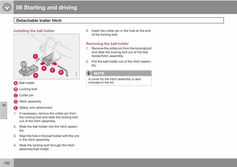
06 Starting and driving
Detachable trailer hitch
06
162
Installing the ball holder
A
C
EDB
G01
0496
Ball holder
Locking bolt
Cotter pin
Hitch assembly
Safety wire attachment
1. If necessary, remove the cotter pin fromthe locking bolt and slide the locking boltout of the hitch assembly.
2. Slide the ball holder into the hitch assem-bly.
3. Align the hole in the ball holder with the onein the hitch assembly.
4. Slide the locking bolt through the hitchassembly/ball holder.
5. Insert the cotter pin in the hole at the endof the locking bolt.
Removing the ball holder1. Remove the cotter pin from the locking bolt
and slide the locking bolt out of the ballholder/hitch assembly.
2. Pull the ball holder out of the hitch assem-bly.
NOTE
A cover for the hitch assembly is alsoincluded in the kit.

06 Starting and driving
Transporting loads
06
163
Loading the vehicleYour vehicle's load-carrying capacity is affec-ted by factors such as:
• the number of passengers
• tire inflation
• the amount of optional or accessory equip-ment installed
• the amount of cargo.
See the chapter "Wheels and tires" for moredetailed information.
Before loading the car, turn off the engine, andapply the parking brake when loading orunloading long objects. The gear selector canbe inadvertently knocked out of position bylong cargo, causing the car to move.
Keep the following in mind whenloading the vehicle:• Load objects in the cargo area against the
rear seat backrest.
• Load heavy cargo as low as possible.
• Center wide loads.
• Secure all cargo with restraining strapsanchored to the load securing eyelets.
• Cover sharp edges on the load.
• Seats can be folded down and headrestraints removed to extend the cargocompartment, see page 111.
WARNING
• Remember that an object weighing44 lbs (20 kg) produces a force of2,200 lbs (1,000 kg) in a head-on colli-sion at 30 mph (50 km/h)!
• When the rear backrest(s) are foldeddown, the vehicle should not be loadedto a level higher than 2 in. (5 cm) belowthe upper edge of the rear side win-dows. Objects placed higher than thislevel could impede the function of theVolvo Inflatable Curtain.
Load carriers (accessory)Load carriers are available as Volvo accesso-ries. Follow the installation instructions sup-plied with the load carriers.
Observe the following points when using loadcarriers:
• To avoid damaging your car and to achievemaximum safety when driving, we recom-mend using the load carriers that Volvo hasdeveloped especially for your car.
• Volvo-approved removable roof racks aredesigned to carry the maximum allowableroof load for this vehicle: 165 lbs (75 kg).For Non-Volvo roof racks, check the man-ufacturer's weight limits for the rack.
• Never exceed the rack manufacturer'sweigh limits and never exceed the maxi-mum rated roof load of 165 lbs (75 kg).
• Avoid single-point loads. Distribute loadsevenly.
• Place heavier cargo at the bottom of theload.
• Secure the cargo correctly with appropri-ate tie-down equipment.
• Check periodically that the load carriersand load are properly secured.
• Remember that the car's center of gravityand handling change when you carry aload on the roof.
• The car's wind resistance and fuel con-sumption will increase with the size of theload.
• Drive smoothly. Avoid rapid starts, fastcornering and hard braking.

06 Starting and driving
Blind Spot Information System (BLIS)–option
06
164
Introduction
G020295
BLIS camera
Indicator light
BLIS symbol
The Blind Spot Information System (BLIS) is aninformation system that indicates the presenceof another vehicle moving in the same directionas your vehicle in the side-view mirror's "blindarea".
CAUTION
The BLIS system should only be repaired bya trained and qualified Volvo service tech-nician.
WARNING
• BLIS is an information system, NOT awarning or safety system.
• BLIS does not eliminate the need foryou to visually confirm the conditionsaround you, and the need for you to turnyour head and shoulders to make surethat you can safely change lanes.
• As the driver, you have full responsibilityfor changing lanes in a safe manner.
The system is based on digital camera tech-nology. The cameras (1) are located beneaththe side-view mirrors.
When one (or both) of the cameras havedetected a vehicle in the blind area (up toapproximately 10 ft. (3 meters) from the side ofyour vehicle, and up to approximately 31 ft.(9.5 meters) behind the side-view mirror), theindicator light in the door panel (2) illuminates.The light will glow continuously to alert thedriver of the vehicle in the blind area.
NOTE
The door panel indicator light illuminates onthe side of the vehicle where the system hasdetected another vehicle. If your vehicle ispassed on both sides at the same time, bothlights will illuminate.
A
B
G020296
A = approx. 10 ft. (3 meters), B = approx. 31 ft.(9.5 meters)
BLIS has an integrated function that alerts thedriver if a fault should occur with the system.For example, if one or both of the system'scameras are obscured, a message (see thetable on page 167) will appear in the informa-tion display in the instrument panel. If thisoccurs, clean the camera lenses. If necessary,the system can be temporarily switched off (forinstructions see page 166).

06 Starting and driving
Blind Spot Information System (BLIS)–option
06
165
When does BLIS functionThe system functions when your vehicle ismoving at speeds above 6 mph (10 km/h).
When you pass another vehicle:
The system reacts when you pass anothervehicle at a speed of up to 6 mph (10 km/h)faster than that vehicle.
When you are passed by another vehicle:
The system reacts if your vehicle is passed byanother vehicle at a speed of up to 43 mph(70 km/h) faster than your vehicle.
WARNING
• BLIS does not function in sharp curves.
• BLIS does not function when your vehi-cle is backing up.
• If you are towing a wide trailer, this mayprevent the BLIS cameras from detect-ing other vehicles in adjacent lanes.
How BLIS functions in daylight anddarkness
DaylightBLIS reacts to the shape of surrounding vehi-cles. The system is designed to help detectmotor vehicles such as cars, trucks, buses,motorcycles, etc.
DarknessBLIS reacts to the headlights of surroundingvehicles. In order to be detected by BLIS, avehicle in the blind area must have its head-lights on. This means, for example, that thesystem will not detect a trailer without head-lights that is being towed behind a car or truck.
WARNING
• BLIS does not react to cyclists ormopeds.
• BLIS does not react to vehicles that arestanding still.
• The function of the BLIS cameras maybe affected by intense light, or whendriving at night in areas where there areno external sources of light (e.g., streetlights, other vehicles, etc.). In suchcases, the system may react as if thecameras were obscured.
• In both of the above mentioned condi-tions, a message will appear in the infor-mation display.
• When driving in such conditions, thesystem's function will be limited or itmay be temporarily switched off, seepage 166 for instructions.
• When the message is no longer dis-played, BLIS will return to normal func-tion.
• The BLIS cameras have the same limi-tation as the human eye. In other words,their "vision is impaired" by adverseweather conditions such as heavysnowfall, dense fog, etc.

06 Starting and driving
Blind Spot Information System (BLIS)–option
06
166
LimitationsIn certain situations, the BLIS indicator light(s)may illuminate even when there are no othervehicles in the area monitored by the system.
NOTE
If the BLIS indicator lights illuminate occa-sionally even when there are no other vehi-cles in the blind area, this does not indicatea fault in the system.
In the event of a fault, Blind spot syst.service required will be displayed.
The following are several examples of situa-tions in which the BLIS indicator light(s) mayilluminate even when there are no other vehi-cles in the area monitored by the system.
G018176
Light reflected from a wet road surface
G018177
The vehicle's own shadow against a large, light,smooth surface such as barriers between lanes ona highway
G018178
Sunlight directly in the camera when the sun is lowon the horizon
Cleaning the BLIS camera lensesIn order to function optimally, the BLIS cameralenses must be kept clean. They can be wipedclean with a soft cloth or wet sponge.
CAUTION
• Clean the lenses carefully to avoidscratching.
• The lenses are electrically heated tohelp melt ice or snow. If necessary, gen-tly brush away snow from the lenses.
Switching BLIS on and off
G018270
BLIS button (left button in the illustration)
BLIS is automatically activated when the igni-tion is switched on. The indicator lights willprovide confirmation by flashing 3 times.
• The system can be switched off by press-ing the BLIS button in the center console.The indicator light in the button goes out
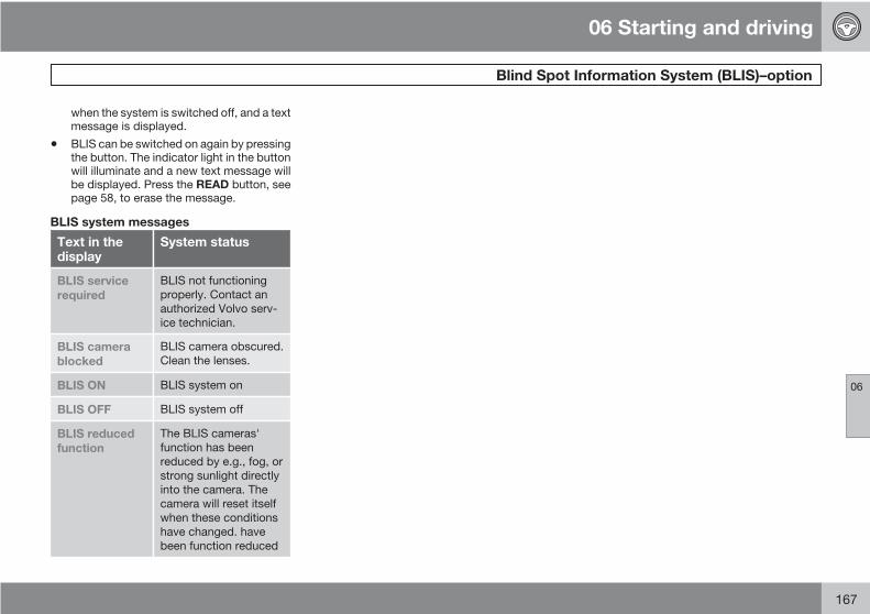
06 Starting and driving
Blind Spot Information System (BLIS)–option
06
167
when the system is switched off, and a textmessage is displayed.
• BLIS can be switched on again by pressingthe button. The indicator light in the buttonwill illuminate and a new text message willbe displayed. Press the READ button, seepage 58, to erase the message.
BLIS system messages
Text in thedisplay
System status
BLIS servicerequired
BLIS not functioningproperly. Contact anauthorized Volvo serv-ice technician.
BLIS camerablocked
BLIS camera obscured.Clean the lenses.
BLIS ON BLIS system on
BLIS OFF BLIS system off
BLIS reducedfunction
The BLIS cameras'function has beenreduced by e.g., fog, orstrong sunlight directlyinto the camera. Thecamera will reset itselfwhen these conditionshave changed. havebeen function reduced
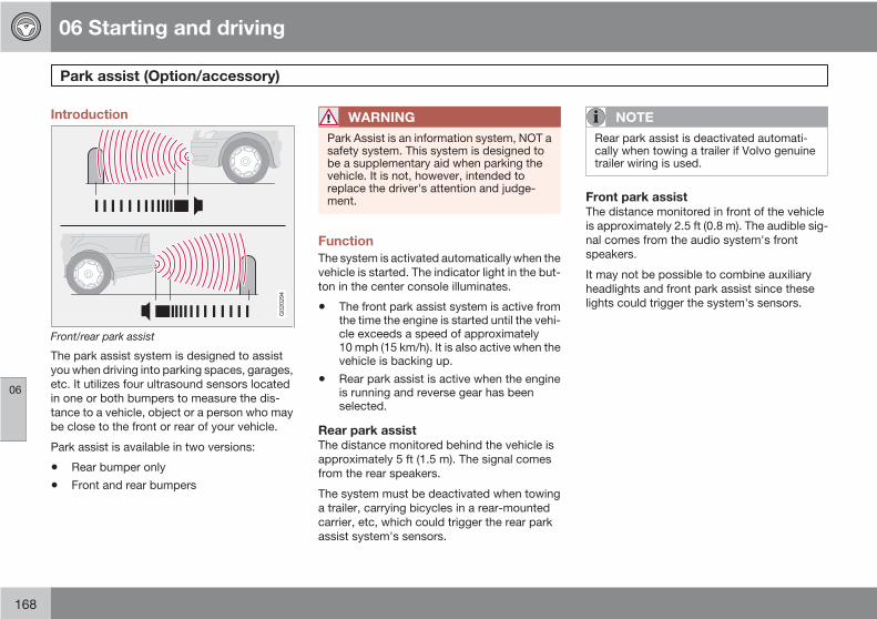
06 Starting and driving
Park assist (Option/accessory)
06
168
Introduction
G020294
Front/rear park assist
The park assist system is designed to assistyou when driving into parking spaces, garages,etc. It utilizes four ultrasound sensors locatedin one or both bumpers to measure the dis-tance to a vehicle, object or a person who maybe close to the front or rear of your vehicle.
Park assist is available in two versions:
• Rear bumper only
• Front and rear bumpers
WARNING
Park Assist is an information system, NOT asafety system. This system is designed tobe a supplementary aid when parking thevehicle. It is not, however, intended toreplace the driver's attention and judge-ment.
FunctionThe system is activated automatically when thevehicle is started. The indicator light in the but-ton in the center console illuminates.
• The front park assist system is active fromthe time the engine is started until the vehi-cle exceeds a speed of approximately10 mph (15 km/h). It is also active when thevehicle is backing up.
• Rear park assist is active when the engineis running and reverse gear has beenselected.
Rear park assistThe distance monitored behind the vehicle isapproximately 5 ft (1.5 m). The signal comesfrom the rear speakers.
The system must be deactivated when towinga trailer, carrying bicycles in a rear-mountedcarrier, etc, which could trigger the rear parkassist system's sensors.
NOTE
Rear park assist is deactivated automati-cally when towing a trailer if Volvo genuinetrailer wiring is used.
Front park assistThe distance monitored in front of the vehicleis approximately 2.5 ft (0.8 m). The audible sig-nal comes from the audio system's frontspeakers.
It may not be possible to combine auxiliaryheadlights and front park assist since theselights could trigger the system's sensors.

06 Starting and driving
Park assist (Option/accessory)
06
169
Activating/deactivating park assist
G021267
Park Assist button (lright button in the illustration)
The system is activated automatically when thevehicle is started.
• Press the Park assist button on the centerconsole to temporarily deactivate the sys-tem(s). The indicator light in the button willgo out when the system has been deacti-vated.
• Park assist will be automatically reactiva-ted the next time the engine is started, or ifthe button is pressed (the indicator light inthe button will illuminate).
NOTE
• Front park assist is disengaged auto-matically when the parking brake isapplied.
• If the vehicle is equipped with front andrear park assist, both systems will bedeactivated by pressing the button.
Audible signals from the park assistsystemThe Park Assist system uses an intermittenttone that pulses faster as you come close to anobject, and becomes constant when you arewithin approximately 1 ft (30 cm) of an objectin front of or behind the vehicle. If the volumeof another source from the audio system ishigh, this will be automatically lowered.
If there are objects within this distance bothbehind and in front of the vehicle, the signalalternates between front and rear speakers.
Faults in the systemIf the information symbol illumi-nates and PARK ASSISTSERVICE REQUIRED is shownon the information display, thisindicates that the system is not
functioning properly and has been disengaged.Consult a Volvo retailer or authorized Volvoservice technician.
CAUTION
In certain circumstances, the park assistsystem may give unexpected warning sig-nals that can be caused by external soundsources that use the same ultrasound fre-quencies as the system. This may includesuch things as the horns of other vehicles,wet tires on asphalt, pneumatic brakes,motorcycle exhaust pipes, etc. This doesnot indicate a fault in the system.

06 Starting and driving
Park assist (Option/accessory)
06
170
Cleaning the sensors
G020770
Park assist sensors
The sensors must be cleaned regularly toensure that they work properly. Clean themwith water and a suitable car washing deter-gent.
Ice and snow covering the sensors may causeincorrect warning signals.
NOTE
If the sensors are obstructed by e.g., dirt,snow, or ice, this could result in false warn-ing signals from the park assist system.

06 Starting and driving
06
171

G020918
172
General information............................................................................... 174Tire inflation........................................................................................... 176Inflation pressure—U.S. models .......................................................... 178Inflation pressure—Canadian models .................................................. 179Tire designations................................................................................... 180Glossary of tire terminology.................................................................. 182Vehicle loading...................................................................................... 183Uniform tire quality gradings................................................................. 185Snow chains, snow tires, studded tires................................................ 186Temporary spare................................................................................... 187Wheel nuts............................................................................................ 188Tire rotation........................................................................................... 189Changing a wheel................................................................................. 190Tire Sealing System ............................................................................. 192Tire Pressure Monitoring System (TPMS)............................................. 197
07WHEELS AND T IRES
07 Wheels and tires
General information
07
174
Your vehicle is equipped with tires accordingto the vehicle's tire information placard on theB-pillar (the structural member at the side ofthe vehicle, at the rear of the driver's dooropening), or on the inside of the fuel filler dooron Canadian models.
CAUTION
Some Volvo models are equipped with anUltra High Performance tire and wheel com-bination designed to provide maximum drypavement performance with considerationfor hydroplaning resistance. As such, theymay be more susceptible to road hazarddamage and, depending on driving condi-tions, may achieve a tread life of less than20,000 miles (30,000 km). Even if this vehi-cle is equipped with Volvo’s advanced AWDor DSTC system, these tires are notdesigned for winter driving, and should bereplaced with winter tires when weatherconditions dictate.
The tires have good road holding characteris-tics and offer good handling on dry and wetsurfaces. It should be noted however that thetires have been developed to give these fea-tures on snow/ice-free surfaces.
Certain models are equipped with "all-season"tires, which provide a somewhat higher degreeof road holding on slippery surfaces than tireswithout the "all-season" rating. However, for
optimum road holding on icy or snow-coveredroads, we recommend suitable winter tires onall four wheels.
When replacing tires, be sure that the new tiresare the same size designation, type (radial) andpreferably from the same manufacturer, on allfour wheels. Otherwise there is a risk of alteringthe car's roadholding and handling characte-ristics.
Storing wheels and tiresWhen storing complete wheels (tires mountedon rims), they should be suspended off thefloor or placed on their sides on the floor.
Tires not mounted on rims should be stored ontheir sides or standing upright, but should notbe suspended.
CAUTION
Tires should preferably be stored in a cool,dry, dark place, and should never be storedin close proximity to solvents, gasoline, oils,etc.
WARNING
• The wheel and tire sizes for your Volvoare specified to meet stringent stabilityand handling requirements. Unap-proved wheel/tire size combinationscan negatively affect your vehicle's sta-bility and handling. Approved tire sizesare shown in the Tire inflation pressuretables, see page 178.
• Any damage caused by installation ofunapproved wheel/tire size combina-tions will not be covered by your newvehicle warranty. Volvo assumes noresponsibility for death, injury, orexpenses that may result from suchinstallations.
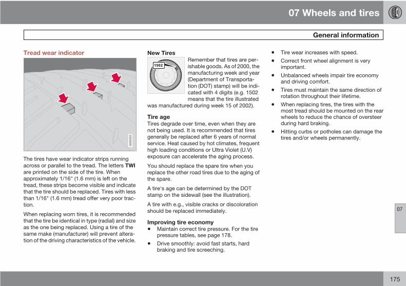
07 Wheels and tires
General information
07
175
Tread wear indicator
G020323
The tires have wear indicator strips runningacross or parallel to the tread. The letters TWIare printed on the side of the tire. Whenapproximately 1/16" (1.6 mm) is left on thetread, these strips become visible and indicatethat the tire should be replaced. Tires with lessthan 1/16" (1.6 mm) tread offer very poor trac-tion.
When replacing worn tires, it is recommendedthat the tire be identical in type (radial) and sizeas the one being replaced. Using a tire of thesame make (manufacturer) will prevent altera-tion of the driving characteristics of the vehicle.
New TiresRemember that tires are per-ishable goods. As of 2000, themanufacturing week and year(Department of Transporta-tion (DOT) stamp) will be indi-cated with 4 digits (e.g. 1502means that the tire illustrated
was manufactured during week 15 of 2002).
Tire ageTires degrade over time, even when they arenot being used. It is recommended that tiresgenerally be replaced after 6 years of normalservice. Heat caused by hot climates, frequenthigh loading conditions or Ultra Violet (U.V)exposure can accelerate the aging process.
You should replace the spare tire when youreplace the other road tires due to the aging ofthe spare.
A tire's age can be determined by the DOTstamp on the sidewall (see the illustration).
A tire with e.g., visible cracks or discolorationshould be replaced immediately.
Improving tire economy• Maintain correct tire pressure. For the tire
pressure tables, see page 178.
• Drive smoothly: avoid fast starts, hardbraking and tire screeching.
• Tire wear increases with speed.
• Correct front wheel alignment is veryimportant.
• Unbalanced wheels impair tire economyand driving comfort.
• Tires must maintain the same direction ofrotation throughout their lifetime.
• When replacing tires, the tires with themost tread should be mounted on the rearwheels to reduce the chance of oversteerduring hard braking.
• Hitting curbs or potholes can damage thetires and/or wheels permanently.

07 Wheels and tires
Tire inflation
07
176
Inflation labels
G032513
Tire inflation placard on U.S. models
Check tire inflation pressure regularly.
Tables listing the recommended inflation pres-sure for your vehicle can be found on page178. A tire inflation pressure placard is alsolocated on the driver's side B-pillar (the struc-tural member at the side of the vehicle, at therear of the driver's door opening). This placardindicates the designation of the factory-moun-ted tires on your vehicle, as well as load limitsand inflation pressure.
G032520
Tire inflation placard on Canadian models
NOTE
The placards shown indicate inflation pres-sure for the tires installed on the car at thefactory only.
Use a tire gauge to check the tire inflation pres-sure, including the spare, at least once a monthand before long trips. You are strongly urgedto buy a reliable tire pressure gauge, as auto-matic service station gauges may be inaccu-rate.
Use the recommended cold inflation pressurefor optimum tire performance and wear.
Under-inflation or over-inflation may causeuneven treadwear patterns.
WARNING
• Under-inflation is the most commoncause of tire failure and may result insevere tire cracking, tread separation,or "blowout," with unexpected loss ofvehicle control and increased risk ofinjury.
• Under-inflated tires reduce the load car-rying capacity of your vehicle.
When weather temperature changes occur, tireinflation pressures also change. A 10-degreetemperature drop causes a correspondingdrop of 1 psi (7 kPa) in inflation pressure. Checkyour tire pressures frequently and adjust themto the proper pressure, which can be found onthe vehicle's tire information placard or certifi-cation label.

07 Wheels and tires
Tire inflation
07
177
Checking tire pressure
Cold tiresInflation pressure should be checked when thetires are cold.
The tires are considered to be cold whenthey have the same temperature as the sur-rounding (ambient) air.
This temperature is normally reached after thecar has been parked for at least 3 hours.
After driving a distance of approximately 1 mile(1.6 km), the tires are considered to be hot. Ifyou have to drive farther than this distance topump your tire(s), check and record the tirepressure first and add the appropriate air pres-sure when you get to the pump.
If checking tire pressure when the tire is hot,never "bleed" or reduce air pressure. The tiresare hot from driving and it is normal for pres-sures to increase above recommended coldpressures. A hot tire at or below recommendedcold inflation pressure could be significantlyunder-inflated.
To check inflation pressure:1. Remove the cap from the valve on one tire,
then firmly press the tire gauge onto thevalve.
2. Add air to reach the recommended airpressure
3. Replace the valve cap.
4. Repeat this procedure for each tire, includ-ing the spare.
5. Visually inspect the tires to make sure thereare no nails or other objects embeddedthat could puncture the tire and cause anair leak.
6. Check the sidewalls to make sure there areno gouges, cuts, bulges or other irregular-ities.
NOTE
• If you overfill the tire, release air bypushing on the metal stem in the centerof the valve. Then recheck the pressurewith your tire gauge.
• Some spare tires require higher inflationpressure than the other tires. Consultthe tire inflation tables, see page 178,or see the inflation pressure placard.
Load ratingsThe load ratings in the tables above translateas follows:
91 = 1365 lbs (615 kg), 93 = 1433 lbs (650 kg),99 = 1709 lbs (755 kg)
Speed ratingsThe speed ratings in the tables translate as fol-lows:
M = 81 mph (130 km/h), V= 149 mph (240 km/h), W= 168 mph (270 km/h)
See also page 180 for an explanation of thedesignations on the sidewall of the tire.

07 Wheels and tires
Inflation pressure—U.S. models
07
178
Tire inflation pressure tableThe following tire pressures are recommendedby Volvo for your vehicle. Refer to the tire infla-
tion placard for information specific to the tiresinstalled on your vehicle at the factory.
Tire size Cold tire pressure up to five persons psi (kPa)
Front Rear
205/55R16 91V M+S 32 (220) 32 (220)
205/50R17 93V
Extra Load M+S
35 (240) 35 (240)
215/45R18A 93W
Extra load
35 (240) 35 (240)
Temporary spare tire
T125/85R16 99M
61 (420) 61 (420)
A Tires of this type may not be mounted on vehicles equipped with the optional self-leveling system.
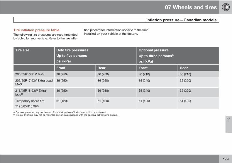
07 Wheels and tires
Inflation pressure—Canadian models
07
179
Tire inflation pressure tableThe following tire pressures are recommendedby Volvo for your vehicle. Refer to the tire infla-
tion placard for information specific to the tiresinstalled on your vehicle at the factory.
Tire size Cold tire pressures
Up to five persons
psi (kPa)
Optional pressure
Up to three personsA
psi (kPa)
Front Rear Front Rear
205/55R16 91V M+S 36 (250) 36 (250) 30 (210) 30 (210)
205/50R17 93V Extra LoadM+S
36 (250) 36 (250) 35 (240) 32 (220)
215/45R18 93W ExtraloadB
36 (250) 36 (250) 35 (240) 32 (220)
Temporary spare tire
T125/85R16 99M
61 (420) 61 (420) 61 (420) 61 (420)
A Optional pressure may not be used for homologation of fuel consumption or emissions.B Tires of this type may not be mounted on vehicles equipped with the optional self-leveling system.

07 Wheels and tires
Tire designations
07
180
Tire designations
1
2
3
4
5
6
12
11
10
8
7 9
G026442
Federal law mandates that tire manufacturersplace standardized information on the sidewallof all tires (see the illustration).
The following information is listed on the tiresidewall:
The tire designation (the following figures areexamples of a tire designation):
215: The width of the tire (in millimeters)from sidewall edge to sidewall edge. Thelarger the number, the wider the tire.
65: The ratio of the tire's height to its width.
R: Radial tire.
15: The diameter of the wheel rim (ininches).
95: The tire's load index. In this example, aload index of 95 equals a maximum load of1521 lbs (690 kg).
H: The tire's speed rating, or the maximumspeed at which the tire is designed to bedriven for extended periods of time, carry-ing a permissible load for the vehicle, andwith correct inflation pressure. For exam-ple, H indicates a speed rating of 130 mph(210 km/h).
NOTE
This information may not appear on the tirebecause it is not required by law.
M+S or M/S = Mud and Snow, AT = AllTerrain, AS = All Season
U.S. DOT Tire Identification Number(TIN): This begins with the letters "DOT"and indicates that the tire meets all federalstandards. The next two numbers or lettersare the plant code where it was manufac-tured, the next two are the tire size codeand the last four numbers represent theweek and year the tire was built. For exam-ple, the numbers 317 mean the 31st weekof 1997. After 2000 the numbers go to fourdigits. For example, 2501 means the 25thweek of 2001. The numbers in between aremarketing codes used at the manufactur-er's discretion. This information helps a tiremanufacturer identify a tire for safety recallpurposes.
Tire Ply Composition and Material Used:Indicates the number of plies indicates orthe number of layers of rubber-coated fab-ric in the tire tread and sidewall. Tire man-ufacturers also must indicate the ply mate-rials in the tire and the sidewall, whichinclude steel, nylon, polyester, and others.

07 Wheels and tires
Tire designations
07
181
Maximum Load: Indicates the maximumload in pounds and kilograms that can becarried by the tire. Refer to the vehicle's tireinformation placard or the safety certifica-tion label, located on the B-Pillar or thedriver's door or on the inside of the fuel fillerdoor on Canadian models, for the correcttire pressure for your vehicle.
Treadwear, Traction, and Temperaturegrades: See page 185 for more informa-tion.
Maximum permissible inflationpressure: The greatest amount of air pres-sure that should ever be put in the tire. Thislimit is set by the tire manufacturer.
The tire suppliers may have additional mark-ings, notes or warnings such as standard load,radial tubeless, etc.

07 Wheels and tires
Glossary of tire terminology
07
182
Terminology• Tire information placard: A placard
showing the OE (Original Equipment) tiresizes, recommended inflation pressure,and the maximum weight the vehicle cancarry.
• Tire Identification Number (TIN): A num-ber on the sidewall of each tire providinginformation about the tire brand and man-ufacturing plant, tire size and date of man-ufacturer.
• Inflation pressure: A measure of theamount of air in a tire.
• Standard load: A class of P-metric or Met-ric tires designed to carry a maximum loadat 35 psi [37 psi (2.5 bar) for Metric tires].Increasing the inflation pressure beyondthis pressure will not increase the tires loadcarrying capability.
• Extra load: A class of P-metric or Metrictires designed to carry a heavier maximumload at 41 psi [43 psi (2.9 bar) for Metrictires]. Increasing the inflation pressurebeyond this pressure will not increase thetires load carrying capability.
• kPa: Kilopascal, a metric unit of air pres-sure.
• PSI: Pounds per square inch, a standardunit of air pressure.
• B-pillar: The structural member at the sideof the vehicle behind the front door.
• Bead area of the tire: Area of the tire nextto the rim.
• Sidewall of the tire: Area between thebead area and the tread.
• Tread area of the tire: Area of the perim-eter of the tire that contacts the road whenmounted on the vehicle.
• Rim: The metal support (wheel) for a tire ora tire and tube assembly upon which thetire beads are seated.
• Maximum load rating: a figure indicatingthe maximum load in pounds and kilo-grams that can be carried by the tire. Thisrating is established by the tire manufac-turer.
• Maximum permissible inflation pres-sure: the greatest amount of air pressurethat should ever be put in the tire. This limitis set by the tire manufacturer.
• Recommended tire inflation pressure:inflation pressure, established by Volvo,which is based on the type of tires that aremounted on a vehicle at the factory. Thisinflation pressure is affected by the numberof occupants in the car, the amount ofcargo, and the speed at which the vehiclewill be driven for a prolonged period. Thisinformation can be found on the tire infla-tion placard(s) located on the driver's side
B-pillar or on the inside of the fuel filler dooron Canadian models, and in the tire infla-tion table in this chapter.
• Cold tires: The tires are considered to becold when they have the same temperatureas the surrounding (ambient) air. This tem-perature is normally reached after the carhas been parked for at least 3 hours.
Properly loading your vehicle will provide maxi-mum return of vehicle design performance.

07 Wheels and tires
Vehicle loading
07
183
Loading the vehicleBefore loading your vehicle, familiarize yourselfwith the following terms for determining yourvehicle's weight ratings, with or without atrailer, from the vehicle's Federal/CanadianMotor Vehicle Safety Standards (FMVSS/CMVSS) label, and the vehicle's tire informa-tion placard:
Curb weightThe weight of the vehicle including a full tankof fuel and all standard equipment. It does notinclude passengers, cargo, or optional equip-ment.
Capacity weightAll weight added to the curb weight, includingcargo and optional equipment. When towing,trailer hitch tongue load is also part of cargoweight.
NOTE
For trailer towing information, please refer tothe section "Towing a trailer", seepage 160.
Permissible axle weightThe maximum allowable weight that can becarried by a single axle (front or rear). Thesenumbers are shown on the Federal/Canadian
Motor Vehicle Safety Standards (FMVSS/CMVSS) label. The total load on each axle mustnever exceed its maximum permissible weight.
Gross vehicle weight (GVW)The vehicle's curb weight + cargo + passen-gers.
NOTE
• The location of the various labels in yourvehicle can be found on page 262.
• A table listing important weight limits foryour vehicle can be found on page265.
Steps for Determining Correct LoadLimit(1) Locate the statement "the combined weightof occupants and cargo should never exceedXXX pounds" on your vehicle's placard.
(2) Determine the combined weight of the driverand passengers that will be riding in your vehi-cle.
(3) Subtract the combined weight of the driverand passengers from XXX kilograms or XXXpounds.
(4) The resulting figure equals the availableamount of cargo and luggage load capacity.For example, if the "XXX" amount equals1400 lbs. and there will be five 150 lbs. pas-sengers in your vehicle, the amount of availablecargo and luggage load capacity is 650 lbs.(1400–750 (5×150) = 650 lbs.)
(5) Determine the combined weight of luggageand cargo being loaded on the vehicle. Thatweight may not safely exceed the availablecargo and luggage load capacity calculated inStep 4.
(6) If your vehicle will be towing a trailer, loadfrom your trailer will be transferred to your vehi-cle. Consult this manual1 to determine how thisreduces the available cargo and luggage loadcapacity of your vehicle.
1 See "Towing a trailer"

07 Wheels and tires
Vehicle loading
07
184
WARNING
• Exceeding the permissible axle weight,gross vehicle weight, or any otherweight rating limits can cause tire over-heating resulting in permanent defor-mation or catastrophic failure.
• Do not use replacement tires with lowerload carrying capacities than the tiresthat were original equipment on thevehicle because this will lower the vehi-cle's GVW rating. Replacement tireswith a higher limit than the originals donot increase the vehicle's GVW ratinglimitations.

07 Wheels and tires
Uniform tire quality gradings
07
185
Uniform tire quality gradingsALL PASSENGER VEHICLE TIRES MUSTCONFORM TO FEDERAL SAFETYREQUIREMENTS IN ADDITION TO THESEGRADES
Quality grades can be found, where appli-cable, on the tire sidewall between the treadshoulder and maximum section width. Forexample:
Treadwear 200 Traction AA
Temperature A
TREADWEARThe treadwear grade is a comparative ratingbased on the wear rate of the tire when testedunder controlled conditions on a specified gov-ernment test course. For example, a tire gra-ded 150 would wear one and one half (1 1/2)times as well on the government course as atire graded 100. The relative performance oftires depends upon the actual conditions oftheir use, however, and many depart signifi-cantly from the norm due to variation in drivinghabits, maintenance practices and differencesin road characteristics and climate.
TRACTIONThe traction grades, from highest to lowest, areAA, A, B, and C, as measured under controlledconditions on specified government test sur-
faces of asphalt and concrete. A tire marked Cmay have poor traction performance. The trac-tion grade assigned to this tire is based onbraking (straight-ahead) traction tests and isnot a measure of cornering (turning) traction.
WARNING
The traction grade assigned to this tire isbased on braking (straight-ahead) tractiontests and is not a measure of cornering(turning) traction.
TEMPERATUREThe temperature grades are AA (the highest),A, B, and C, representing the tire's resistanceto the generation of heat and its ability to dis-sipate heat when tested under controlled con-ditions on a specified indoor laboratory testwheel. Sustained high temperature can causethe material of the tire to degenerate andreduce tire life, and excessive temperature canlead to sudden tire failure. The grade C corre-sponds to a minimum level of performance thatall passenger vehicle tires must meet under theFederal Motor Safety Standard No. 109.Grades B and A represent higher levels of per-formance on the laboratory test wheel than theminimum required by law.
WARNING
The temperature grade for this tire is estab-lished for a tire that is properly inflated andnot overloaded. Excessive speed, under-inflation, or excessive loading, either sepa-rately or in combination, can cause heatbuildup and tire failure.

07 Wheels and tires
Snow chains, snow tires, studded tires
07
186
Snow chainsSnow chains can be used on your Volvo withthe following restrictions:
• Snow chains should be installed on frontwheels only. Use only Volvo approvedsnow chains.
• If accessory, aftermarket or "custom" tiresand wheels are installed and are of a sizedifferent than the original tires and wheels,chains in some cases CANNOT be used.Sufficient clearances between chains andbrakes, suspension and body componentsmust be maintained.
• Some strap-on type chains will interferewith brake components and thereforeCANNOT be used.
• All Wheel Drive models: Snow chainsshould only be installed on the frontwheels. Only chains adapted for AWDmodels should be used.
Consult your Volvo retailer for additional snowchain information.
CAUTION
• Check local regulations regarding theuse of snow chains before installing.
• Always follow the chain manufacturer'sinstallation instructions carefully. Installchains as tightly as possible andretighten periodically.
• Never exceed the chain manufacturer'sspecified maximum speed limit. (Underno circumstances should you exceed31 mph (50 km/h).
• Avoid bumps, holes or sharp turnswhen driving with snow chains.
• The handling of the vehicle can beadversely affected when driving withchains. Avoid fast or sharp turns as wellas locked wheel braking.
Snow tires, studded tires
Tires for winter use:• Owners who live in or regularly commute
through areas with sustained periods ofsnow or icy driving conditions are stronglyadvised to fit suitable winter tires to helpretain the highest degree of traction.
• It is important to install winter tires on allfour wheels to help retain traction duringcornering, braking, and accelerating. Fail-
ure to do so could reduce traction to anunsafe level or adversely affect handling.
• Do not mix tires of different design as thiscould also negatively affect overall tire roadgrip.
• Winter tires wear more quickly on dry roadsin warm weather. They should be removedwhen the winter driving season has ended.
• Studded tires should be run-in 300–600 miles (500–1000 km) during which thecar should be driven as smoothly as pos-sible to give the studs the opportunity toseat properly in the tires. The tires shouldhave the same rotational directionthroughout their entire lifetime.
NOTE
Please consult state or provincial regula-tions restricting the use of studded wintertires before installing such tires.

07 Wheels and tires
Temporary spare
07
187
Temporary spareThe spare tire in your car is called a "TemporarySpare".
Recommended tire pressure (see the placardon the B-pillar or on the fuel filler door) shouldbe maintained irrespective of which position onthe car the temporary spare tire is used on.
In the event of damage to this tire, a new onecan be purchased from your Volvo retailer.
WARNING
Current legislation prohibits the use of the"Temporary Spare" tire other than as a tem-porary replacement for a punctured tire. Itmust be replaced as soon as possible by astandard tire. Road holding and handlingmay be affected with the "TemporarySpare" in use. Do not exceed a speed of50 mph (80 km/h) with the "TemporarySpare" in use.
CAUTION
The car must not be driven with wheels ofdifferent dimensions or with a spare tireother than the one that came with the car.The use of different size wheels can seri-ously damage your car's transmission.

07 Wheels and tires
Wheel nuts
07
188
Wheel nuts
G020324
Low nut.
High nut.
There are two different types of wheel nut,depending on whether the wheels are steel oraluminum.
Steel rims – low nutSteel rims are normally secured using the lowtype of nut, although steel rims may also usethe high type.
WARNING
Never use the short type of nut for alumi-nium wheels. This could cause the wheel tocome loose.
Aluminum wheels – high nutOnly the high type of nut can be used for alu-minum wheels. This is considerably differentfrom other types of nut because it has a rotat-ing conical thrust washer.
NOTE
This nut can also be used on steel wheels.
Lockable wheel nutIf steel wheels with lockable wheel nuts areused in combination with wheel covers, thelockable wheel nut must be fitted to the studnearest the air valve. The wheel cover cannototherwise be installed on the wheel.

07 Wheels and tires
Tire rotation
07
189
G020325
The arrows shows the direction of rotation of thetire
Summer and winter tires• When switching between summer and
winter tires, mark the tires to indicatewhere they were mounted on the car, e.g.,LF = left front, RR = right rear
• Tires with tread designed to roll in only onedirection are marked with an arrow on thesidewall.
• Incorrectly mounted tires impair the car'sbraking properties and ability to forceaside rain, snow and slush.
• The tires with the most tread should alwaysbe at the rear (to reduce the risk of skid-ding).
• Contact a Volvo workshop if you areunsure about the tread depth.
Tire rotationYour vehicle has no recommended tire rota-tion. The following information is intended tohelp you understand why.
Tread setAs a tire ages and the rubber cures, front andrear tires set at different angles. Therefore, iftires are rotated, the tread will eventually set atan angle that is a compromise. Even if ride,handling, and road noise may still seemacceptable, they may not be optimal. Further,tires that are rotated, but not on a regular basis,may actually cause more tire noise, faster tirewear, and unpleasant changes in steering feeland vehicle handling.
A tire that can fully adapt to its position willprovide better steering feel, lower tire noise,and better fuel economy.
Braking stability performanceYour vehicle is driven mainly by the front tires,which will wear faster. This can be beneficial.Having more tread on the rear tires will helpreduce oversteer. Oversteer is when a vehiclewants to keep turning because of momentumand dynamic forces on its suspension.
Suspension wear diagnosticsEvery suspension needs periodic inspectionand maintenance. A tire's wear pattern can be
an aid in detecting a suspension problem. Eachtire, if left in place, tells a story about the sus-pension. Tire rotation, on the other hand, couldmake suspension wear harder to detect. Earlydetection is very important, because suspen-sion problems can make tire wear worse.
If you do rotate your tires…Please follow the tire manufacturer's recom-mendations, as outlined in the tire manufactur-ers tire warranty pamphlet.
Your Volvo retailer can also provide guidancebased on your particular driving circumstan-ces.
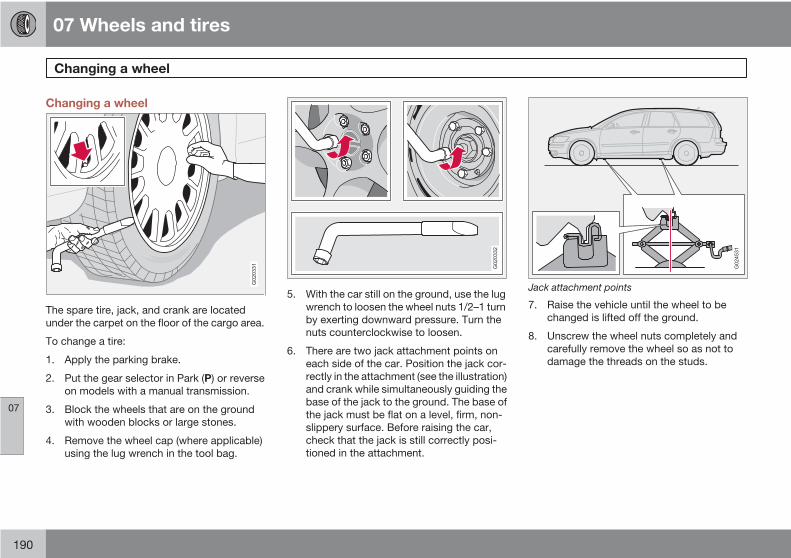
07 Wheels and tires
Changing a wheel
07
190
Changing a wheel
G020331
The spare tire, jack, and crank are locatedunder the carpet on the floor of the cargo area.
To change a tire:
1. Apply the parking brake.
2. Put the gear selector in Park (P) or reverseon models with a manual transmission.
3. Block the wheels that are on the groundwith wooden blocks or large stones.
4. Remove the wheel cap (where applicable)using the lug wrench in the tool bag.
G020332
5. With the car still on the ground, use the lugwrench to loosen the wheel nuts 1/2–1 turnby exerting downward pressure. Turn thenuts counterclockwise to loosen.
6. There are two jack attachment points oneach side of the car. Position the jack cor-rectly in the attachment (see the illustration)and crank while simultaneously guiding thebase of the jack to the ground. The base ofthe jack must be flat on a level, firm, non-slippery surface. Before raising the car,check that the jack is still correctly posi-tioned in the attachment.
G024531
Jack attachment points
7. Raise the vehicle until the wheel to bechanged is lifted off the ground.
8. Unscrew the wheel nuts completely andcarefully remove the wheel so as not todamage the threads on the studs.
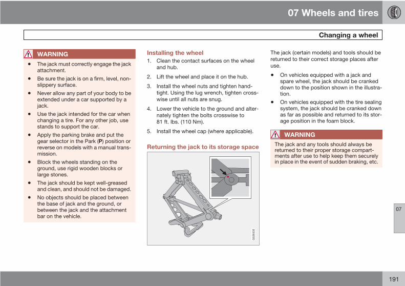
07 Wheels and tires
Changing a wheel
07
191
WARNING
• The jack must correctly engage the jackattachment.
• Be sure the jack is on a firm, level, non-slippery surface.
• Never allow any part of your body to beextended under a car supported by ajack.
• Use the jack intended for the car whenchanging a tire. For any other job, usestands to support the car.
• Apply the parking brake and put thegear selector in the Park (P) position orreverse on models with a manual trans-mission.
• Block the wheels standing on theground, use rigid wooden blocks orlarge stones.
• The jack should be kept well-greasedand clean, and should not be damaged.
• No objects should be placed betweenthe base of jack and the ground, orbetween the jack and the attachmentbar on the vehicle.
Installing the wheel1. Clean the contact surfaces on the wheel
and hub.
2. Lift the wheel and place it on the hub.
3. Install the wheel nuts and tighten hand-tight. Using the lug wrench, tighten cross-wise until all nuts are snug.
4. Lower the vehicle to the ground and alter-nately tighten the bolts crosswise to81 ft. lbs. (110 Nm).
5. Install the wheel cap (where applicable).
Returning the jack to its storage space
G029335
The jack (certain models) and tools should bereturned to their correct storage places afteruse.
• On vehicles equipped with a jack andspare wheel, the jack should be crankeddown to the position shown in the illustra-tion.
• On vehicles equipped with the tire sealingsystem, the jack should be cranked downas far as possible and returned to its stor-age position in the foam block.
WARNING
The jack and any tools should always bereturned to their proper storage compart-ments after use to help keep them securelyin place in the event of sudden braking, etc.
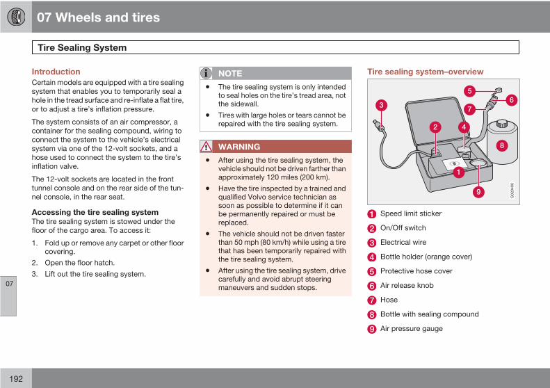
07 Wheels and tires
Tire Sealing System
07
192
IntroductionCertain models are equipped with a tire sealingsystem that enables you to temporarily seal ahole in the tread surface and re-inflate a flat tire,or to adjust a tire’s inflation pressure.
The system consists of an air compressor, acontainer for the sealing compound, wiring toconnect the system to the vehicle’s electricalsystem via one of the 12-volt sockets, and ahose used to connect the system to the tire’sinflation valve.
The 12-volt sockets are located in the fronttunnel console and on the rear side of the tun-nel console, in the rear seat.
Accessing the tire sealing systemThe tire sealing system is stowed under thefloor of the cargo area. To access it:
1. Fold up or remove any carpet or other floorcovering.
2. Open the floor hatch.3. Lift out the tire sealing system.
NOTE
• The tire sealing system is only intendedto seal holes on the tire’s tread area, notthe sidewall.
• Tires with large holes or tears cannot berepaired with the tire sealing system.
WARNING
• After using the tire sealing system, thevehicle should not be driven farther thanapproximately 120 miles (200 km).
• Have the tire inspected by a trained andqualified Volvo service technician assoon as possible to determine if it canbe permanently repaired or must bereplaced.
• The vehicle should not be driven fasterthan 50 mph (80 km/h) while using a tirethat has been temporarily repaired withthe tire sealing system.
• After using the tire sealing system, drivecarefully and avoid abrupt steeringmaneuvers and sudden stops.
Tire sealing system–overview
G020400
Speed limit sticker
On/Off switch
Electrical wire
Bottle holder (orange cover)
Protective hose cover
Air release knob
Hose
Bottle with sealing compound
Air pressure gauge

07 Wheels and tires
Tire Sealing System
07
193
WARNING
Please keep the following points in mindwhen using the tire sealing system:
• The sealing compound bottle (no. 8 inthe illustration) contains 1.2-Ethanoland natural rubber-latex. These sub-stances are harmful if swallowed.
• The contents of this bottle may causeallergic skin reactions or otherwise bepotentially harmful to the skin, the cen-tral nervous system, and the eyes.
Precautions:
• Keep out of reach of children.
• Do not ingest the contents.
• Avoid prolonged or repeated contactwith the skin.
• Hands should be washed thoroughlyafter handling.
First aid:
• Skin: Wash affected areas of skin withsoap and water. Get medical attentionif symptoms occur.
• Eyes: Flush with plenty of water for least15 minutes, occasionally lifting theupper and lower eyelids. Get medicalattention if symptoms occur.
• Inhalation: Move the person to fresh air.If irritation persists, get medical atten-tion.
Tire sealing system–temporarilyrepairing a flat tire
G01
4338
Temporarily repairing a flat tire is done in twostages:
• Stage 1: The hole is sealed by pumpingsealing compound into the tire. The car isthen driven a short distance to distributethe sealing compound in the tire.
NOTE
Do not remove any foreign objects (nails,etc.) from the tire before using the sealingsystem.
• Stage 2: The tire’s inflation pressure ischecked and adjusted if necessary.
WARNING
• Never leave the tire sealing systemunattended when it is operating.
• Keep the tire sealing system away fromchildren.
• Be sure the vehicle is parked safely offthe road and away from moving traffic.
• Apply the parking brake.
Stage 1: Sealing the hole1. Open the cover on the tire sealing kit.
2. Peel off the speed limit sticker and affix itto the steering wheel hub where it will beclearly visible to the driver.
07 Wheels and tires
Tire Sealing System
07
194
3. Ensure that the on/off switch is in position0 (the 0 side of the switch should bepressed down).
4. Put on the gloves included in the tire seal-ing system.
WARNING
Contact with the sealing compound maycause skin irritation. If contact occurs, washthe affected area immediately with soap andwater.
5. Unscrew the orange cover over the bottleholder and unscrew the cap on the bottleof sealing compound.
NOTE
Do not break the seal on the bottle. Thisoccurs automatically when the bottle isscrewed into the holder.
6. Screw the bottle into the bottle holder.
WARNING
The bottle is equipped with a catch to keepit securely in place and help prevent sealingcompound leakage. Once in place, the bot-tle cannot be unscrewed. This must be doneby a trained and qualified Volvo servicetechnician.
7. Remove the valve cap from the tire’s infla-tion valve and screw the tire sealing sys-tem’s hose connector onto the valve astightly as possible by hand.
8. Connect the electrical wire to the nearest12-volt socket in the vehicle.
9. Start the vehicle’s engine.
10. Start the tire sealing system’s compressorby pressing the on/off switch to position I.
WARNING
• Never stand next to the tire being inflatedwhen the compressor is in operation.
• If cracks, bubbles, etc. form on the tire,switch off the compressor immediately.
• If there is visible damage to the sidewallor the rim, the tire cannot be repaired.The vehicle should not be driven if thisoccurs. Contact a towing service orVolvo On Call Roadside Assistance ifapplicable.
NOTE
The air pressure gauge will temporarilyshow an increase in pressure to approxi-mately 88 psi (6 bar) while the sealing com-pound is being pumped into the tire. Thepressure should return to a normal levelafter approximately 30 seconds.
11. Within seven minutes, inflate the tire tobetween 22—44 psi (1.8—3.0 bar). Switchoff the compressor briefly to get a clearreading from the pressure gauge. Thecompressor should not be used for morethan 10 minutes at a time to avoid over-heating.

07 Wheels and tires
Tire Sealing System
07
195
CAUTION
The compressor should not be used formore than 10 minutes at a time to avoidoverheating.
WARNING
If the pressure remains below 22 psi (1.8bar) after approximately seven minutes, turnoff the compressor. In this case, the hole istoo large to be sealed and the vehicle shouldnot be driven.
12. Switch off the compressor and disconnectthe electrical wire from the 12-volt socket.
13. Unscrew the hose from the tire’s inflationvalve and reinstall the valve cap.
14. Immediately drive the vehicle for approxi-mately 2 miles (3 km) at a maximum speedof 50 mph (80 km/h) to distribute the seal-ing compound in the tire.
NOTE
• Safely stow the tire sealing system in aconvenient place as it will soon be usedagain to check the tire’s inflation pres-sure.
• The empty bottle of sealing compoundcannot be removed from the bottleholder. Consult a trained and qualifiedVolvo service technician to have thebottle removed and properly disposedof.
WARNING
If heavy vibrations, unsteady steeringbehavior, or noises should occur while driv-ing, reduce speed and park the vehicle in asafe place. Recheck the tire for bumps,cracks, or other visible damage, andrecheck its inflation pressure. If the pressureis below 19 psi (1.3 bar), do not continuedriving. Have the vehicle towed to a trainedand qualified Volvo service technician.
Stage 2: Checking inflation pressure1. Connect the tire sealing system as descri-
bed in stage 1.
2. Refer to the inflation pressure tablesfor thecorrect inflation pressure. If the tire needsto be inflated, start the tire sealing system’scompressor. If necessary, release air from
the tire by turning the air release knobcounterclockwise.
CAUTION
The compressor should not be used formore than 10 minutes at a time to avoidoverheating.
WARNING
If you interrupt your trip for more than 1hour, check the inflation pressure in thedamaged tire again before continuing.
Replacing the sealing compoundcontainerThe sealing compound container must bereplaced if:
• the tire sealing system has been used torepair a tire
• the container’s expiration date has passed(see the date on decal).

07 Wheels and tires
Tire Sealing System
07
196
NOTE
• After use, the sealing compound bottle,the hose, and certain other systemcomponents must be replaced. Pleaseconsult your Volvo retailer for replace-ment parts.
• If the sealing compound bottle’s expi-ration date has passed, please take it toa Volvo retailer or a recycling stationthat can properly dispose of harmfulsubstances.
Inflating tiresThe tire sealing system can be used to inflatethe tires. To do so:
1. Park the car in a safe place.
2. The compressor should be switched off.Ensure that the on/off switch is in posi-tion 0 (the 0 side of the switch should bepressed down).
3. Take out the electrical wire and hose.
4. Remove the valve cap from the tire’s infla-tion valve and screw the hose connectoronto the valve as tightly as possible byhand.
5. Connect the electrical wire to the nearest12-volt socket in the vehicle.
6. Start the vehicle’s engine.
WARNING
• The vehicle’s engine should be runningwhen the tire sealing system is used toavoid battery drain. Therefore, be surethe vehicle is parked in a well ventilatedplace, or outdoors, before using the sys-tem.
• Children should never be left unattendedin the vehicle when the engine is running.
7. Check the tire’s inflation pressure on thegauge. Switch off the compressor briefly toget a clear reading from the pressuregauge.
8. Refer to the tire inflation tables for the cor-rect inflation pressure. If the tire needs tobe inflated, start the tire sealing system’scompressor (press the on/off switch toposition I). If necessary, release air from thetire by turning the air release knob coun-terclockwise.
CAUTION
The compressor should not be used formore than 10 minutes at a time to avoidoverheating.
9. Turn off the compressor (press the on/offswitch to position 0) when the correct infla-tion pressure has been reached.
10. Unscrew the hose from the tire’s inflationvalve and reinstall the valve cap.
11. Disconnect the electrical wire from the12-volt socket.

07 Wheels and tires
Tire Pressure Monitoring System (TPMS)
07
197
IntroductionThe tire pressure monitoring system uses sen-sors mounted in the tire valves to check infla-tion pressure levels. When the vehicle ismoving at a speed of approximately 20 mph(30 km/h) or faster, these sensors transmitinflation pressure data to a receiver located inthe vehicle.
NOTE
USA – FCC ID: KR5S122780002
This device complies with part 15 of theFCC rules. Operation is subject to the fol-lowing conditions: (1) This device may notcause harmful interference, and (2) thisdevice must accept any interferencereceived, including interference that maycause undesired operation.
When low inflation pressure is detected, TPMSwill light up the tire pressure warning light (alsoreferred to as a telltale) in the instrument panel,and will display a message in the text window.The wording of this message is determined bythe degree of inflation pressure loss.
NOTE
If a fault occurs in TPMS, the tire pressurewarning light will flash for approximately1 minute and TIRE PRESS SYSTSERVICE REQUIRED will be displayed.
Each tire, including the spare (if provided),should be checked monthly when cold andinflated to the inflation pressure recommendedby the vehicle manufacturer on the vehicleplacard or tire inflation pressure label. (If yourvehicle has tires of a different size than the sizeindicated on the vehicle placard or tire inflationpressure label, you should determine theproper tire inflation pressure for those tires.)
As an added safety feature, your vehicle hasbeen equipped with a tire pressure monitoringsystem (TPMS) that illuminates a low tire pres-sure telltale when one or more of your tires issignificantly under-inflated. Accordingly, whenthe low tire pressure telltale illuminates, youshould stop and check your tires as soon aspossible, and inflate them to the proper pres-sure. Driving on a significantly under-inflatedtire causes the tire to overheat and can lead totire failure. Under-inflation also reduces fuelefficiency and tire tread life, and may affect thevehicle's handling and stopping ability.
Please note that the TPMS is not a substitutefor proper tire maintenance, and it is the driv-
er's responsibility to maintain correct tire pres-sure, even if under-inflation has not reachedthe level to trigger illumination of the TPMS lowtire pressure telltale.
Your vehicle has also been equipped with aTPMS malfunction indicator to indicate whenthe system is not operating properly. TheTPMS malfunction indicator is combined withthe low tire pressure telltale. When the systemdetects a malfunction, the telltale will flash forapproximately one minute and then remaincontinuously illuminated. This sequence willcontinue upon subsequent vehicle start-ups aslong as the malfunction exists. When the mal-function indicator is illuminated, the systemmay not be able to detect or signal low tirepressure as intended. TPMS malfunctions mayoccur for a variety of reasons, including theinstallation of replacement or alternate tires orwheels on the vehicle that prevent the TPMSfrom functioning properly. Always check theTPMS malfunction telltale after replacing oneor more tires or wheels on your vehicle toensure that the replacement or alternate tiresand wheels allow the TPMS to continue tofunction properly.
07 Wheels and tires
Tire Pressure Monitoring System (TPMS)
07
198
NOTE
• TPMS indicates low tire pressure butdoes not replace normal tire mainte-nance. For information on correct tirepressure, please refer to the tablesbeginning, see page 178, or consultyour Volvo retailer.
• The tire pressure warning light will notidentify which tire is underinflated. Besure to check all four tires.
• A certain amount of air seepage fromthe tires occurs naturally and tire pres-sure fluctuates with seasonal changesin temperature. Always check tire pres-sure regularly.
Erasing warning messagesWhen a low tire pressure warning message hasbeen displayed, and the tire pressure warninglight has come on:
1. Use a tire pressure gauge to check theinflation pressure of all four tires.
2. Re-inflate the tire(s) to the correct pressure(consult the tire pressure placard or thetables, see page 178 ).
3. In certain cases, it may be necessary todrive the vehicle for several minutes at aspeed of 20 mph (30 km/h) or faster. This
will erase the warning text and the warninglight will go out.
WARNING
Incorrect inflation pressure could lead to tirefailure, resulting in a loss of control of thevehicle.
Changing wheels with TPMSPlease note the following when changing orreplacing the factory installed TPMS wheels/tires on the vehicle:
• Only the factory-mounted wheels areequipped with TPMS sensors in the valves.
• If the vehicle is equipped with a temporaryspare tire, this tire does not have a TPMSsensor.
• If wheels without TPMS sensors are moun-ted on the vehicle, TIRE PRESS SYSTSERVICE REQUIRED will be displayedeach time the vehicle is driven above25 mph (40 km/h) for 10 minutes or more.
• Once TPMS sensors are properly installed,the warning message should not reappear.If the message is still displayed, drive thevehicle for several minutes at a speed of20 mph (30 km/h) or faster to erase themessage.
• Volvo recommends that TPMS sensors befitted on all wheels used on the vehicle.
Volvo does not recommend moving sen-sors back and forth between sets ofwheels.
NOTE
• If you change to tires with a differentrecommended inflation pressure, theTPMS system must be recalibrated tothese tires. This must be done by anauthorized Volvo retailer or workshop.
• If a tire is changed, or if the TPMS sen-sor is moved to another wheel, the sen-sor's seal, nut, and valve core should bereplaced.
• When installing TPMS sensors, thevehicle must be parked for at least15 minutes with the ignition off. If thevehicle is driven within 15 minutes, aTPMS error message will be displayed.
CAUTION
When inflating tires with TPMS valves, pressthe pump's mouthpiece straight onto thevalve to help avoid bending or otherwisedamaging the valve.
07 Wheels and tires
07
199

G020920
200
Washing and cleaning the car............................................................... 202Paint touch up....................................................................................... 206

08CAR CARE
08 Car care
Washing and cleaning the car
08
202
Washing the carThe following points should be kept in mindwhen washing and cleaning the car:
• The car should be washed at regular inter-vals since dirt, dust, insects and tar spotsadhere to the paint and may cause dam-age. To help prevent corrosion, it is partic-ularly important to wash the car frequentlyin the wintertime when salt has been usedon the roads.
• Avoid washing your car in direct sunlight.Doing so may cause detergents and waxto dry out and become abrasive. To avoidscratching, use lukewarm water to softenthe dirt before you wash with a softsponge, and plenty of sudsy water.
• Bird droppings: Remove from paintworkas soon as possible. Otherwise the finishmay be permanently damaged.
• A detergent can be used to facilitate thesoftening of dirt and oil.
• A water-soluble grease solvent may beused in cases of sticky dirt. However, usea wash place equipped with a drainageseparator.
• Dry the car with a clean chamois andremember to clean the drain holes in thedoors and rocker panels.
• Tar spots can be removed with keroseneor tar remover after the car has beenwashed.
• A stiff-bristle brush and lukewarm soapywater can be used to clean the wiperblades. Frequent cleaning of the wind-shield and wiper blades improves visibilityconsiderably and also helps prolong theservice life of the wiper blades.
• Wash off the dirt from the underside (wheelhousings, fenders, etc).
• In areas of high industrial fallout, more fre-quent washing is recommended.
• After cleaning the engine, the spark plugwells should be inspected for water andblown dry if necessary.
NOTE
When washing the car, remember to removedirt from the drain holes in the doors andsills.
Exterior componentsVolvo recommends the use of special cleaningproducts, available at your Volvo retailer, forcleaning colored plastic, rubber, or ornamentalcomponents such as chromed strips on theexterior of your vehicle. The instructions forusing these products should be followed care-
fully.Solvents or stain removers should not beused.
CAUTION
• Avoid waxing or polishing plastic or rub-ber components
• Polishing chromed strips can wearaway or damage the surface
• Polishes containing abrasive sub-stances should not be used
08 Car care
Washing and cleaning the car
08
203
CAUTION
• During high pressure washing, thespray mouthpiece must never be closerto the vehicle than 13" (30 cm). Do notspray into the locks.
• Dirt, snow, etc., on the headlights canreduce lighting capacity considerably.Clean the headlights regularly, forexample when refueling.
• When washing or steam cleaning theengine, avoid spraying water or steamdirectly on the electrical components ortoward the rear side of the engine.
• Always close the moonroof (option) andsun shade before washing your vehicle.
• Never use abrasive cleaning agents onthe moonroof.
• Never use wax on the rubber sealsaround the moonroof.
Automatic washing – simple and quickWe do NOT recommend washing your car in anautomatic wash during the first six months(because the paint will not have hardened suf-ficiently).
An automatic wash is a simple and quick wayto clean your car, but it is worth rememberingthat it may not be as thorough as when youyourself go over the car with sponge and water.
Keeping the underbody clean is most impor-tant, especially in the winter. Some automaticwashers do not have facilities for washing theunderbody.
CAUTION
• Before driving into an automatic carwash, turn off the optional rain sensorto avoid damaging the windshield wip-ers.
• Make sure that side view mirrors, auxil-iary lamps, etc, are secure, and that anyantenna(s) are retracted or removed.Otherwise there is risk of the machinedislodging them
• Chromed wheels: Clean chrome-plated wheels using the same deter-gents used for the body of the vehicle.Aggressive wheel-cleaning agents canpermanently stain chrome-platedwheels.
WARNING
• When the car is driven immediately afterbeing washed, apply the brakes severaltimes in order to remove any moisturefrom the brake linings.
• Engine cleaning agents should not beused when the engine is warm. Thisconstitutes a fire risk.
Exterior lightingCondensation may form temporarily on theinside of the lenses of exterior lights such asheadlights, fog lights, or taillights. This is nor-mal and the lights are designed to withstandmoisture. Normally, condensation will dissi-pate after the lights have been on for a shorttime.
Polishing and Waxing• Normally, polishing is not required during
the first year after delivery, however, wax-ing may be beneficial.
• Before applying polish or wax the vehiclemust be washed and dried. Tar spots canbe removed with kerosene or tar remover.Difficult spots may require a fine rubbingcompound.
• After polishing use liquid or paste wax.
• Several commercially available productscontain both polish and wax.
• Waxing alone does not substitute for pol-ishing a dull surface.
• A wide range of polymer-based waxes canbe purchased today. These waxes are easyto use and produce a long-lasting, high-gloss finish that protects the bodyworkagainst oxidation, road dirt and fading.
• Do not polish or wax your vehicle in directsunlight (the surface of the vehicle shouldnot be warmer than 113 °F (45 °C).

08 Car care
Washing and cleaning the car
08
204
CAUTION
Volvo does not recommend the use of long-life or durable paint protection coatings,some of which may claim to prevent pitting,fading, oxidation, etc. These coatings havenot been tested by Volvo for compatibilitywith your vehicle's clear coat. Some of themmay cause the clear coat to soften, crack,or cloud. Damage caused by application ofpaint protection coatings may not be cov-ered under your vehicle's paint warranty.
Upholstery care
FabricClean with soapy water or a detergent. Formore difficult spots caused by oil, ice cream,shoe polish, grease, etc., use a clothing/fabricstain remover. Consult your Volvo retailer.
Interior plastic componentsCleaning interior plastic components shouldbe done with a cleaning agent speciallydesigned for this purpose. Consult your Volvoretailer.
Alcantera™ suede-like materialSuede-like upholstery can be cleaned with asoft cloth and mild soap solution.
Leather careVolvo's leather upholstery is manufacturedwith a protectant to repel soiling. Over time,sunlight, grease and dirt can break down theprotection. Staining, cracking, scuffing, andfading can result.
Volvo offers an easy-to-use, non-greasyleather care kit formulated to clean and beau-tify your vehicle's leather, and to renew theprotective qualities of its finish. The cleanerremoves dirt and oil buildup. The light creamprotectant restores a barrier against soil andsunlight.
Volvo also offers a special leather softener thatshould be applied after the cleaner and pro-tectant. It leaves leather soft and smooth, andreduces friction between leather and other fin-ishes in the vehicle.
Volvo recommends cleaning, protecting andconditioning your vehicle's leather two to fourtimes a year. Ask your Volvo retailer aboutLeather Care Kit 951 0251 and Leather Soft-ener 943 7429.
Cleaning leather upholstery1. Pour leather cleaner on a damp sponge
and squeeze it until the cleaner foams.
2. Apply the foam to the stain by moving thesponge with circular movements.
3. Dampen the stain thoroughly with thesponge. Let the sponge absorb the stain,do not rub.
4. Dry the stain with soft paper towels or atowel, and allow the leather to dry com-pletely.
Protecting leather upholstery1. Put a small amount of protectant cream on
a cloth and apply a thin coating of creamto the upholstery with light circular move-ments.
2. Allow the leather to dry for 20 minutes.
This will help the leather resist staining andprotect against sunlight's harmful UV rays.

08 Car care
Washing and cleaning the car
08
205
CAUTION
• Under no circumstances should gaso-line, naphtha or similar cleaning agentsbe used on the plastic or the leathersince these can cause damage.
• Take extra care when removing stainssuch as ink or lipstick since the coloringcan spread.
• Use solvents sparingly. Too much sol-vent can damage the seat padding.
• Start from the outside of the stain andwork toward the center.
• Sharp objects (e.g. pencils or pens in apocket) or Velcro fasteners on clothingmay damage the textile upholstery.
• Clothing that is not colorfast, such asnew jeans or suede garments, may stainthe upholstery.
Cleaning the seat beltsClean only with lukewarm water and a mildsoap solution.
Cleaning floor matsThe floor mats should be vacuumed or brushedclean regularly, especially during winter whenthey should be taken out for drying. Spots ontextile mats can be removed with a mild deter-gent. For best protection in winter, Volvo rec-ommends the use of Volvo rubber floor mats.Consult your Volvo retailer.

08 Car care
Paint touch up
08
206
Touching up minor paint damagePaint damage requires immediate attention toavoid rusting. Make it a habit to check the finishregularly - when washing the vehicle forinstance. Touch-up if necessary.
Paint repairs require special equipment andskill. Contact a trained and authorized Volvoservice technician for any extensive damage.Minor scratches can be repaired by usingVolvo touch-up paint.
Color codeG031024
When ordering touch-up paint from your Volvoretailer, make sure you have the right color.Use the paint code indicated on the modelplate (1 in the illustration).
Minor stone chips and scratchesMaterial:
• Primer – can
• Paint – touch-up pen
• Brush
• Masking tape
G020345
NOTE
When touching up the vehicle, it should beclean and dry. The surface temperatureshould be above 60° F (15° C).
If the stone chip has not penetrated downto the metal and an undamaged layer ofpaint remains, the touch-up paint can beapplied as soon as the spot has beencleaned.
Deep scratches1. Place a strip of masking tape over the dam-
aged surface. Pull the tape off so that anyloose flakes of paint adhere to it.
2. Thoroughly mix the primer and apply it witha small brush. When the primer surface isdry, the paint can be applied using a brush.Mix the paint thoroughly; apply several thinpaint coats and let dry after each applica-tion.
3. If there is a longer scratch, you may wantto protect surrounding paint by masking itoff.
08 Car care
08
207
G020922
208
Volvo maintenance................................................................................ 210Maintaining your car.............................................................................. 212Hood..................................................................................................... 214Engine compartment............................................................................. 215Engine oil............................................................................................... 216Fluids..................................................................................................... 218Wiper blades......................................................................................... 220Battery................................................................................................... 221Replacing bulbs.................................................................................... 223Fuses..................................................................................................... 230

09MAINTENANCE AND SERVICING

09 Maintenance and servicing
Volvo maintenance09
210
GeneralVolvo advises you to follow the maintenanceprogram outlined in the Warranty and ServiceRecords Information booklet. This mainte-nance program contains inspections and serv-ices necessary for the proper function of yourvehicle. The maintenance services containseveral checks that require special tools andtraining, and therefore must be performed by aqualified technician. To keep your Volvo in topcondition, specify time-tested and provenGenuine Volvo Parts and Accessories.
The Federal Clean Air Act – U.SThe Federal Clean Air Act requires vehiclemanufacturers to furnish written instructions tothe ultimate purchaser to assure the properservicing and function of the components thatcontrol emissions. These services, which arelisted in the "Warranty and Service RecordsInformation" booklet, are not covered by thewarranty. You will be required to pay for laborand material used.
MaintenanceYour Volvo passed several major inspectionsbefore it was delivered to you, in accordancewith Volvo specifications. The maintenanceprocedures outlined in the Warranty and Serv-ice Records Information booklet, many ofwhich will positively affect your vehicle's emis-sions, should be performed as indicated. It isrecommended that receipts for vehicle emis-sion maintenance be retained in case ques-tions arise concerning maintenance. Inspec-tion and maintenance should also beperformed anytime a malfunction is observedor suspected.
Applicable warranties – U.S/CanadaIn accordance with applicable U.S. and Cana-dian regulations, the following list of warrantiesis provided.
• New Vehicle Limited Warranty
• Parts and Accessories Limited Warranty
• Corrosion Protection Limited Warranty
• Seat Belt and Supplemental Restraint Sys-tems Limited Warranty
• Emission Design and Defect Warranty
• Emission Performance Warranty
These are the federal warranties; other warran-ties are provided as required by state/provin-cial law. Refer to your separate Warranty and
Service Records Information booklet fordetailed information concerning each of thewarranties.
Periodic maintenance helps minimizeemissionsPeriodic maintenance will help keep your vehi-cle running well. Your Warranty and ServiceRecords Information booklet provides a com-prehensive periodic maintenance schedule upto 150,000 miles (240,000 km) of vehicle main-tenance. The schedule includes componentsthat affect vehicle emissions. This pagedescribes some of the emission-related com-ponents.
Vehicle Event Data (Black Box)Your vehicle's driving and safety systemsemploy computers that monitor, and sharewith each other, information about your vehi-cle's operation. One or more of these comput-ers may store what they monitor, either duringnormal vehicle operation or in a crash or near-crash event. Stored information may be readand used by:
• Volvo Car Corporation
• service and repair facilities

09 Maintenance and servicing
Volvo maintenance 09
211
• law enforcement or government agencies
• others who may assert a legal right toknow, or who obtain your consent to knowsuch information.

09 Maintenance and servicing
Maintaining your car09
212
Owner maintenancePeriodic maintenance requirements and inter-vals are described in your vehicle's Warrantyand Service Records Information booklet.
The following points can be carried outbetween the normally scheduled maintenanceservices.
Each time the car is refueled:• Check the engine oil level.
• Clean the windshield, windshield wipers,headlights, and taillights.
Monthly:• Check cold tire pressure in all tires. Inspect
the tires for wear.
• Check that engine coolant and other fluidlevels are between the indicated "min" and"max" markings.
• Clean interior glass surfaces with a glasscleaner and soft paper towels.
• Wipe driver information displays with a softcloth.
• Visually inspect battery terminals for cor-rosion. Corrosion may indicate a loose ter-minal connector, or a battery near the endof its useful service life. Consult a trainedand qualified Volvo service technician foradditional information.
As needed:• Wash the car, including the undercarriage,
to reduce wear that can be caused by abuildup of dirt, and corrosion that can becaused by salt residues.
• Clean leaves and twigs from air intakevents at the base of the windshield, andfrom other places where they may collect.
NOTE
Complete service information for qualifiedtechnicians is available online for purchaseor subscription at www.volvotechinfo.com.
Emission inspection readiness
What is an Onboard Diagnostic System(OBD II)?OBD II is part of your vehicle's computerizedengine management system. It stores diagnos-tic information about your vehicle's emissioncontrols. It can light the Check Engine light(MIL) if it detects an emission control "fault." A"fault" is a component or system that is notperforming within an expected range. A faultmay be permanent or temporary. OBD II willstore a message about any fault.
How Do States Use OBD II for EmissionInspections?Many states connect a computer directly to avehicle's OBD II system. The inspector canthen read "faults." In some states, this type ofinspection has replaced the tailpipe emissiontest.
How Can My Vehicle Fail OBD II EmissionInspection?Your vehicle can fail OBD II emission inspec-tion for any of the following reasons.
• If your Check Engine (MIL) light is lit, yourvehicle may fail inspection.
• If your vehicle's Check Engine light was lit,but went out without any action on yourpart, OBD II will still have a recorded fault.Your vehicle may pass or fail, dependingon the inspection practices in your area.
• If you had recent service that required dis-connecting the battery, OBD II diagnosticinformation may be incomplete and "notready" for inspection. A vehicle that is notready may fail inspection.
How Can I Prepare for My Next OBD IIEmission Inspection?• If your Check Engine (MIL) light is lit – or
was lit but went out without service, have
09 Maintenance and servicing
Maintaining your car 09
213
your vehicle diagnosed and, if necessary,serviced by a qualified Volvo technician.
• If you recently had service for a lit CheckEngine light, or if you had service thatrequired disconnecting the battery, aperiod of driving is necessary to bring theOBD II system to "ready" for inspection. Ahalf-hour trip of mixed stop-and-go/high-way driving is typically needed to allowOBD II to reach readiness. Your Volvoretailer can provide you with more infor-mation on planning a trip.
• Maintain your vehicle in accordance withyour vehicle's maintenance schedule.
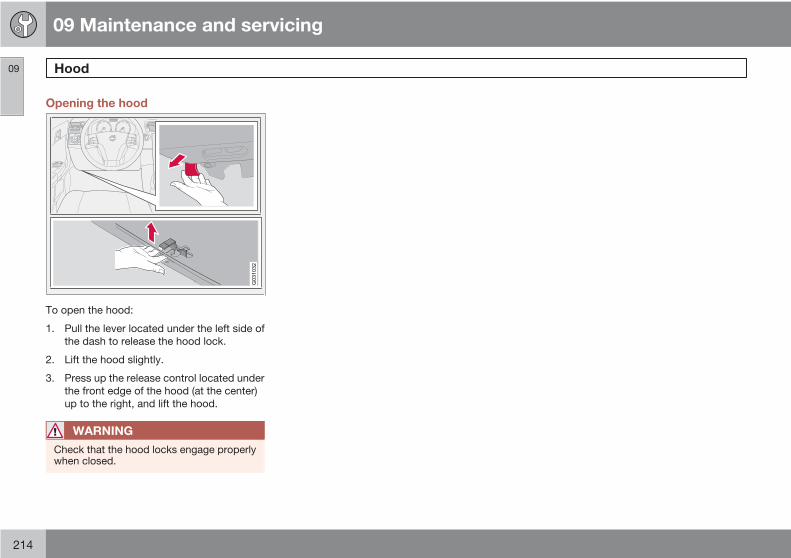
09 Maintenance and servicing
Hood09
214
Opening the hood
G031032
To open the hood:
1. Pull the lever located under the left side ofthe dash to release the hood lock.
2. Lift the hood slightly.
3. Press up the release control located underthe front edge of the hood (at the center)up to the right, and lift the hood.
WARNING
Check that the hood locks engage properlywhen closed.
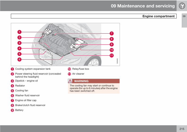
09 Maintenance and servicing
Engine compartment 09
215
G026456
Cooling system expansion tank
Power steering fluid reservoir (concealedbehind the headlight)
Dipstick – engine oil
Radiator
Cooling fan
Washer fluid reservoir
Engine oil filler cap
Brake/clutch fluid reservoir
Battery
Relay/fuse box
Air cleaner
WARNING
The cooling fan may start or continue tooperate (for up to 6 minutes) after the enginehas been switched off.
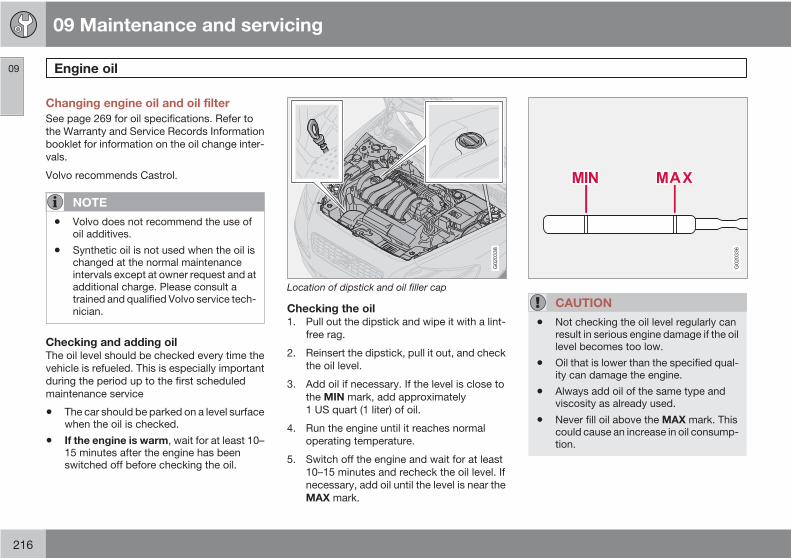
09 Maintenance and servicing
Engine oil09
216
Changing engine oil and oil filterSee page 269 for oil specifications. Refer tothe Warranty and Service Records Informationbooklet for information on the oil change inter-vals.
Volvo recommends Castrol.
NOTE
• Volvo does not recommend the use ofoil additives.
• Synthetic oil is not used when the oil ischanged at the normal maintenanceintervals except at owner request and atadditional charge. Please consult atrained and qualified Volvo service tech-nician.
Checking and adding oilThe oil level should be checked every time thevehicle is refueled. This is especially importantduring the period up to the first scheduledmaintenance service
• The car should be parked on a level surfacewhen the oil is checked.
• If the engine is warm, wait for at least 10–15 minutes after the engine has beenswitched off before checking the oil.
G020338
Location of dipstick and oil filler cap
Checking the oil1. Pull out the dipstick and wipe it with a lint-
free rag.
2. Reinsert the dipstick, pull it out, and checkthe oil level.
3. Add oil if necessary. If the level is close tothe MIN mark, add approximately1 US quart (1 liter) of oil.
4. Run the engine until it reaches normaloperating temperature.
5. Switch off the engine and wait for at least10–15 minutes and recheck the oil level. Ifnecessary, add oil until the level is near theMAX mark.
G020336
CAUTION
• Not checking the oil level regularly canresult in serious engine damage if the oillevel becomes too low.
• Oil that is lower than the specified qual-ity can damage the engine.
• Always add oil of the same type andviscosity as already used.
• Never fill oil above the MAX mark. Thiscould cause an increase in oil consump-tion.
09 Maintenance and servicing
Engine oil 09
217
WARNING
Do not allow oil to spill onto or come intocontact with hot exhaust pipe surfaces
NOTE
Volvo uses different systems to indicate alow oil level or pressure. Some models havean oil pressure sensor, in which case awarning symbol (see page 55) is used toindicate low oil pressure. Other models havean oil level sensor, in which case the driveris alerted by the warning symbol in the cen-ter of the instrument panel and a text in theinformation display. Some models use bothsystems. Contact an authorized Volvoretailer for more information.

09 Maintenance and servicing
Fluids09
218
Washer fluid
G026425
Washer fluid reservoir
The washer fluid reservoir is located in theengine compartment and holds approximately6.8 US qts (6.5 liters). During cold weather, thereservoir should be filled with windshieldwasher solvent containing antifreeze.
Coolant
G020334
Coolant reservoir
Normally, the coolant does not need to bechanged. If the system must be drained, con-sult a trained and qualified Volvo service tech-nician.
CAUTION
• If necessary, top up the cooling systemwith Volvo Genuine Coolant/Antifreezeonly (a 50/50 mix of water and anti-freeze).
• Different types of antifreeze/coolantmay not be mixed.
• If the cooling system is drained, itshould be flushed with clean water orpremixed anti-freeze before it is refilledwith the correct mixture of water/anti-freeze.
• The cooling system must always bekept filled to the correct level, and thelevel must be between the MIN andMAX marks. If it is not kept filled, therecan be high local temperatures in theengine which could result in damage.Check coolant regularly!
• Do not top up with water only. Thisreduces the rust-protective and anti-freeze qualities of the coolant and has alower boiling point. It can also causedamage to the cooling system if itshould freeze.
• Do not use chlorinated tap water in thevehicles cooling system.

09 Maintenance and servicing
Fluids 09
219
WARNING
Never remove the radiator cap while theengine is warm. Wait until the vehicle cools.
If it is necessary to top off the coolant whenthe engine is warm, unscrew the expansiontank cap slowly so that the overpressuredissipates.
Brake fluid
G020333
Brake fluid reservoir
The brake fluid should always be between theMIN and MAX marks on the side of the reser-voir. Check, without removing the cap, thatthere is sufficient fluid in the reservoir.
Fluid type: DOT 4+ boiling point >536 °F
(280 °C), P/N 9437433
Replace: The fluid should be replaced accord-ing to the intervals specified in the Warrantyand Service Records Information booklet.When driving under extremely hard conditions(mountain driving, etc), it may be necessary toreplace the fluid more often. Consult yourVolvo retailer. Always entrust brake fluidchanging to a trained and qualified Volvo serv-ice technician.
Power steering fluidThe fluid level is checked at each service inter-val.
Fluid type: Volvo power steering fluid or equiv-alent.
Replace: No fluid change required.
WARNING
If a problem should occur in the powersteering system or if the vehicle has no elec-trical current and must be towed, it is stillpossible to steer the vehicle. However, keepin mind that greater effort will be required toturn the steering wheel.
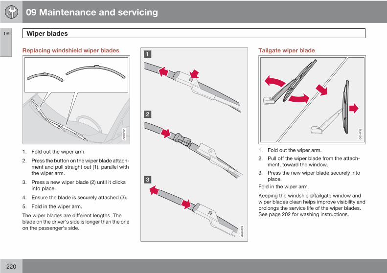
09 Maintenance and servicing
Wiper blades09
220
Replacing windshield wiper blades
G020330
1. Fold out the wiper arm.
2. Press the button on the wiper blade attach-ment and pull straight out (1), parallel withthe wiper arm.
3. Press a new wiper blade (2) until it clicksinto place.
4. Ensure the blade is securely attached (3).
5. Fold in the wiper arm.
The wiper blades are different lengths. Theblade on the driver's side is longer than the oneon the passenger's side.
G020329
Tailgate wiper blade
G014732
1. Fold out the wiper arm.
2. Pull off the wiper blade from the attach-ment, toward the window.
3. Press the new wiper blade securely intoplace.
Fold in the wiper arm.
Keeping the windshield/tailgate window andwiper blades clean helps improve visibility andprolongs the service life of the wiper blades.See page 202 for washing instructions.

09 Maintenance and servicing
Battery 09
221
Battery maintenanceDriving habits and conditions, climate, thenumber of starts, etc., all affect the service lifeand function of the battery. In order for yourbattery to perform satisfactorily, keep the fol-lowing in mind:
Check the fluid level in each cell in the batteryevery 24 months or every 15,0001 miles(24,000 km), whichever is sooner.
• Use a screw driver to open the caps orcover and a flashlight to inspect the level.
• If necessary, add distilled water. The levelshould never be above the indicator.
• The fluid level should be checked if thebattery has been recharged.
• After inspection, be sure the cap over eachbattery cell or the cover is securely inplace.
• Check that the battery cables are correctlyconnected and properly tightened.
• Never disconnect the battery when theengine is running, or when the key is in theignition. This could damage the vehicle'selectrical system.
• The battery should be disconnected fromthe vehicle when a battery charger is useddirectly on the battery.
WARNING
PROPOSITION 65 WARNING!
Battery posts, terminals, and related acces-sories contain lead and lead compounds,chemicals known to the state of Californiato cause cancer and reproductive harm.Wash hands after handling.
Battery symbols:Wear protection goggles
See owner's manual fordetails
Keep away from children
Corrosive
No smoking, no open flames,no sparks
Explosion
Battery replacement
Removing the battery1. Switch off the ignition and remove the key.
2. Wait at least 5 minutes after switching offthe ignition before disconnecting the bat-tery so that all information in the vehicle'selectrical system can be stored in the con-trol modules.
1 More frequently in warm climates.

09 Maintenance and servicing
Battery09
222
3. Remove the cover over the battery.
4. Disconnect the battery negative (ground)cable.
5. Disconnect the positive cable.
6. Remove the front side of the battery boxwith a screwdriver.
7. Release the clamp holding the battery.
8. Lift out the battery.
Installing a new battery1. Put the battery in place in the engine com-
partment.
2. Install the battery's retaining clamp.
3. Reinstall the front side of the battery box.
4. Connect the positive cable.
5. Connect the ground cable.
6. Reinstall the cover over the battery.
NOTE
Used batteries should be properly disposedof at a recycling station or similar facility, ortaken to your Volvo retailer.
WARNING
• Never expose the battery to open flameor electric spark.
• Do not smoke near the battery.
• Battery fluid contains sulfuric acid. Donot allow battery fluid to contact eyes,skin, fabrics or painted surfaces. If con-tact occurs, flush the affected areaimmediately with water. Obtain medicalhelp immediately if eyes are affected.

09 Maintenance and servicing
Replacing bulbs 09
223
IntroductionBefore replacing bulbs in your vehicle, pleasekeep the following points in mind:
NOTE
Never touch the glass of bulbs with your fin-gers. Grease and oils from your fingersvaporize in the heat and will leave a depositon the reflector, which will damage it.
The optional Bi-Xenon headlight bulbscontain trace amounts of mercury. Thesebulbs should always be disposed of by atrained and qualified Volvo service techni-cian.
Certain bulbs should only be replaced by atrained and qualified Volvo service techni-cian:
• Courtesylighting
• Reading lights
• Glove compartment lights
• Turn signals and courtesy lights in theside door mirrors
• Brake lights
• Bi-Xenon headlights, Brake lights
Removing the headlight housing
WARNING
• The engine should not be running whenchanging bulbs.
• When changing in the headlight hous-ing, if the engine has been running justprior to replacing bulbs, please beaware that components in the enginecompartment will be hot.
G019599
The entire headlight housing must be lifted outwhen replacing the high/low beam, parking
light, turn signal, and side marker bulbs. To liftout the housing:
1. Remove the key from the ignition and turnthe headlight switch to position 0.
2. Open the hood.
3. Pull up the headlight housing's retainingpin.
4. Pull out the headlight housing.
G019600
5. Disconnect the wiring connector by press-ing down the clip with your thumb while atthe same time pulling the connector withyour other hand.

09 Maintenance and servicing
Replacing bulbs09
224
6. Lift out the headlight housing and place iton a soft surface to avoid scratching thelens.
CAUTION
When disconnecting the connector, pull onthe connector itself and not on the wiring.
After the defective bulb has been replaced,reinsert the housing in the reverse order. Checkthat the retaining pin is correctly inserted.
WARNING
Bi-Xenon headlights (option) – due to thehigh voltage used by these headlights,these bulbs should only be replaced by atrained and qualified Volvo service techni-cian.
Low beam bulb
G019131
Cover with retaining clamps
1. Open the hood and remove the headlighthousing (see page 223 for instructions).
2. Release the retaining clamps on the cover.
3. Release the bulb's retaining spring holdingthe bulb in place by pressing it inward anddownward.
4. Pull out the bulb.
G019133
Low beam bulb
Installing a new bulb1. Insert the new bulb. It can only be installed
in one position.
2. Press the retaining spring inward andupward and slightly to the right until itsnaps into place.
3. Press the wiring connector onto the bulb.
4. Put the plastic cover in place.
5. Press the retaining clamps back into place.
6. Reinstall the headlight housing (seepage 223).
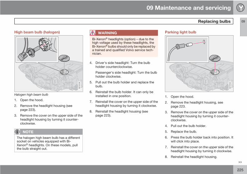
09 Maintenance and servicing
Replacing bulbs 09
225
High beam bulb (halogen)
G019136
Halogen high beam bulb
1. Open the hood.
2. Remove the headlight housing (seepage 223).
3. Remove the cover on the upper side of theheadlight housing by turning it counter-clockwise.
NOTE
The halogen high beam bulb has a differentsocket on vehicles equipped with Bi-Xenon headlights. On these models, pullthe bulb straight out.
WARNING
Bi-Xenon headlights (option) – due to thehigh voltage used by these headlights, theBi-Xenon bulbs should only be replaced bya trained and qualified Volvo service tech-nician.
4. Driver's side headlight: Turn the bulbholder counterclockwise.
Passenger's side headlight: Turn the bulbholder clockwise.
5. Pull out the bulb holder and replace thebulb.
6. Reinstall the bulb holder. It can only beinstalled in one position.
7. Reinstall the cover on the upper side of theheadlight housing by turning it clockwise.
8. Reinstall the headlight housing (seepage 223).
Parking light bulb
G019145
1. Open the hood.
2. Remove the headlight housing, seepage 223.
3. Remove the cover on the upper side of theheadlight housing by turning it counter-clockwise.
4. Pull out the bulb holder.
5. Replace the bulb.
6. Press the bulb holder back into position. Itwill click into place.
7. Reinstall the cover on the upper side of theheadlight housing by turning it clockwise.
8. Reinstall the headlight housing.

09 Maintenance and servicing
Replacing bulbs09
226
Turn signal
G019150
1. Open the hood.
2. Remove the headlight housing, seepage 223.
3. Turn the bulb holder counterclockwise andremove it.
4. Remove the bulb from the holder by press-ing it in and twisting it counterclockwise.
5. Insert a new bulb and reinstall the bulbholder in the headlight housing.
6. Reinstall the headlight housing.
Side marker light
G018050
1. Open the hood.
2. Remove the headlight housing, seepage 223.
3. Turn the bulb holder counterclockwise,pull it out, and replace the bulb.
4. Reinstall the bulb holder. It can only beinstalled in one position.
5. Reinstall the headlight housing.
Front fog light (option)
G019605
1. Switch off all lights and turn the key toposition 0.
2. Remove the panel around the fog lighthousing by inserting a screw driver asshown in the illustration and pressing thepanel outward to release the retainingclips.
3. Grasp the edge of the panel and pull itstraight out.
4. Unscrew the screw in the fog light housingand remove it.
5. Turn the bulb counterclockwise andremove it.
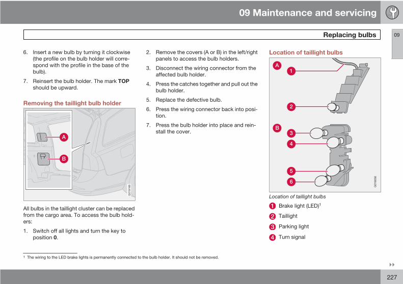
09 Maintenance and servicing
Replacing bulbs 09
227
6. Insert a new bulb by turning it clockwise(the profile on the bulb holder will corre-spond with the profile in the base of thebulb).
7. Reinsert the bulb holder. The mark TOPshould be upward.
Removing the taillight bulb holder
G019166
All bulbs in the taillight cluster can be replacedfrom the cargo area. To access the bulb hold-ers:
1. Switch off all lights and turn the key toposition 0.
2. Remove the covers (A or B) in the left/rightpanels to access the bulb holders.
3. Disconnect the wiring connector from theaffected bulb holder.
4. Press the catches together and pull out thebulb holder.
5. Replace the defective bulb.
6. Press the wiring connector back into posi-tion.
7. Press the bulb holder into place and rein-stall the cover.
Location of taillight bulbs
G018058
Location of taillight bulbs
Brake light (LED)1
Taillight
Parking light
Turn signal
1 The wiring to the LED brake lights is permanently connected to the bulb holder. It should not be removed.

09 Maintenance and servicing
Replacing bulbs09
228
Back-up light
Fog light (driver's side only)
NOTE
If the message indicating a burned out bulbremains in the information display after thebulb has been replaced, consult a trainedand qualified Volvo service technician.
High-level brake lightThese bulbs should only be replaced by atrained and qualified Volvo service technician.
License plate lighting
G014849
1. Switch off all lights and turn the key toposition 0.
2. Remove the screws with a screw driver.
3. Detach the lens (bulb housing) carefully.
4. Replace the defective bulb.
5. Reinstall the entire bulb housing and screwit into place.
Footwell lighting
G020795
The footwell lighting is located under the dash-board on the driver's and passenger's sides.To replace a bulb:
1. Insert a screwdriver under the edge of thelens. Turn the screwdriver gently to detachthe lens.
2. Remove the defective bulb.
3. Install a new bulb.
4. Press the lens back into place.

09 Maintenance and servicing
Replacing bulbs 09
229
Cargo area lighting
G014852
1. Insert a screwdriver and turn it gently todetach the bulb housing.
2. Remove the defective bulb.
3. Install a new bulb.
4. Press the bulb housing back into place.
Vanity mirror lighting
G020253
1. Insert a screwdriver under the center of thelower edge of the mirror, turn it, and care-fully pry up the lugs at the edge.
2. Move the screwdriver under the edge onthe left and right-hand sides (near the blackrubber sections) and pry carefully torelease the lower edge of the mirror.
3. Pry carefully and lift out the entire mirrorand the cover.
4. Remove the defective bulb and replace itwith a new one.
5. To reinstall the mirror, begin by pressingthe three lugs at the upper edge of the mir-ror back into place.
6. Press the three lower lugs back into place.

09 Maintenance and servicing
Fuses09
230
Replacing fusesThere are relay/fuse boxes located in theengine compartment and the passenger com-partment.
If an electrical component fails to function, thismay be due to a blown fuse. The easiest wayto see if a fuse is blown is to remove it.
To do so:
1. Pull the fuse straight out. If a fuse is difficultto remove, special fuse removal tools arelocated on the inside of the fuse box cov-ers.
2. From the side, examine the curved metalwire in the fuse to see if it is intact.
3. If the wire is broken, insert a new fuse ofthe same color and amperage (written onthe fuse).
If fuses burn out repeatedly, have the electricalsystem inspected by a trained and qualifiedVolvo service technician.
WARNING
Never use metal objects or fuses with higheramperage than those stated on the follow-ing pages. Doing so could seriously damageor overload the vehicle's electrical system.

09 Maintenance and servicing
Fuses 09
231
Fuse box in the engine compartment
G007446
The fuse box in the engine compartment haspositions for 36 fuses.
• Fuses 1–18 are relays/circuit breakers andshould only be removed or replaced by anauthorized Volvo service technician.
• Fuses 19–36 may be changed at any timewhen necessary.
Several extra fuses and a fuse removal tool toassist in removing/replacing fuses can befound on the underside of the fuse box coverin the engine compartment.

09 Maintenance and servicing
Fuses09
232
Fuses in the engine compartment
G020250
1. Coolant fan (radiator) 50A
2. Power steering 80A
3. Feed to passenger com-partment fuse box
60A
4. Feed to passenger com-partment fuse box
60A
5. Element, climate unit 80A
6. Not in use
7. ABS pump 30A
8. ABS valves 20A
9. Engine functions 30A
10. Climate system blower 40A
11. Headlight washers 20A
12. Feed to heated rear window 30A
13. Starter motor relay 30A
14. Trailer connector (acces-sory)
40A
15. Not in use
16. Feed to audio system 30A
17. Windshield wipers 30A
18. Feed to passenger com-partment fuse box
40A
19. Not in use
20. Horn 15A
21. Not in use
22. Not in use
23. Engine control module(ECM)/transmission controlmodule (TCM)
10A
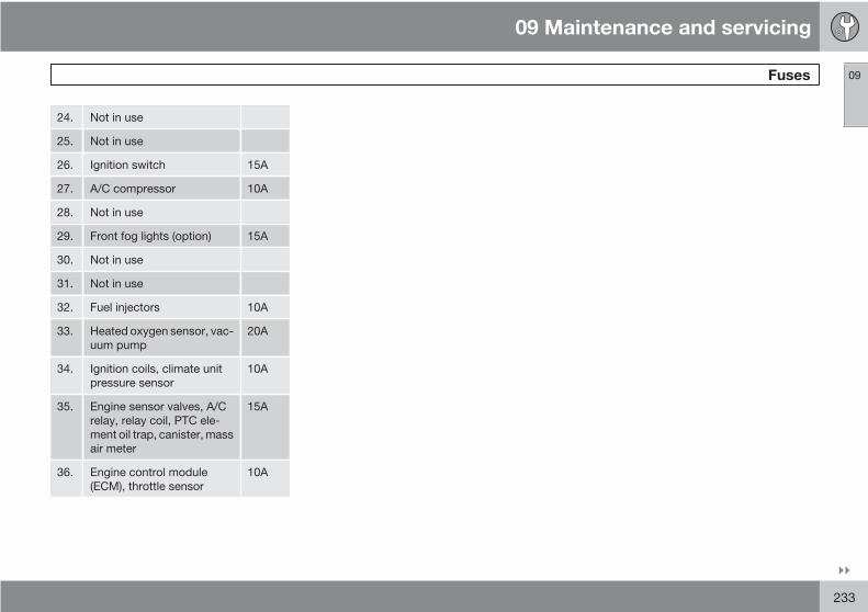
09 Maintenance and servicing
Fuses 09
233
24. Not in use
25. Not in use
26. Ignition switch 15A
27. A/C compressor 10A
28. Not in use
29. Front fog lights (option) 15A
30. Not in use
31. Not in use
32. Fuel injectors 10A
33. Heated oxygen sensor, vac-uum pump
20A
34. Ignition coils, climate unitpressure sensor
10A
35. Engine sensor valves, A/Crelay, relay coil, PTC ele-ment oil trap, canister, massair meter
15A
36. Engine control module(ECM), throttle sensor
10A
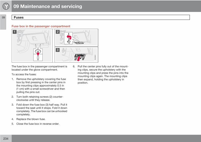
09 Maintenance and servicing
Fuses09
234
Fuse box in the passenger compartment
G020601
The fuse box in the passenger compartment islocated under the glove compartment.
To access the fuses:
1. Remove the upholstery covering the fusebox by first pressing in the center pins inthe mounting clips approximately 0.5 in(1 cm) with a small screwdriver and thenpulling the pins out.
2. Turn both retaining screws (2) counter-clockwise until they release.
3. Fold down the fuse box (3) half way. Pull ittoward the seat until it stops. Fold it downcompletely. The fuse box can be unhookedcompletely.
4. Replace the blown fuse.
5. Close the fuse box in reverse order.
6. Pull the center pins fully out of the mount-ing clips, secure the upholstery with themounting clips and press the pins into themounting clips again. The mounting clipsthen expand, holding the upholstery inposition.
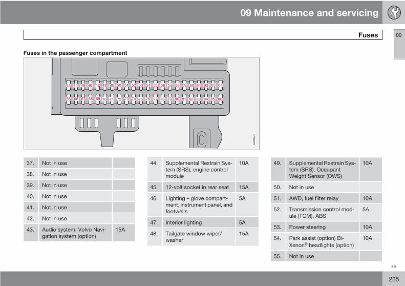
09 Maintenance and servicing
Fuses 09
235
Fuses in the passenger compartment
G020246
37. Not in use
38. Not in use
39. Not in use
40. Not in use
41. Not in use
42. Not in use
43. Audio system, Volvo Navi-gation system (option)
15A
44. Supplemental Restrain Sys-tem (SRS), engine controlmodule
10A
45. 12-volt socket in rear seat 15A
46. Lighting – glove compart-ment, instrument panel, andfootwells
5A
47. Interior lighting 5A
48. Tailgate window wiper/washer
15A
49. Supplemental Restrain Sys-tem (SRS), OccupantWeight Sensor (OWS)
10A
50. Not in use
51. AWD, fuel filter relay 10A
52. Transmission control mod-ule (TCM), ABS
5A
53. Power steering 10A
54. Park assist (option) Bi-Xenon headlights (option)
10A
55. Not in use
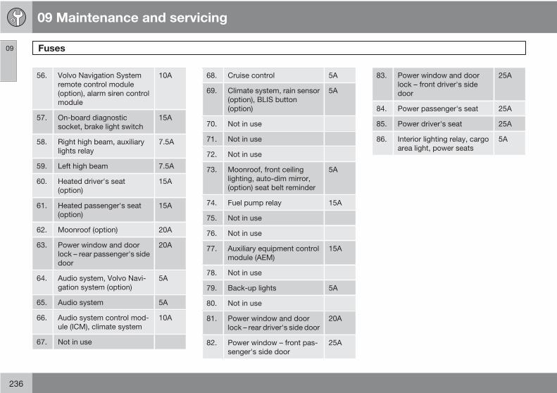
09 Maintenance and servicing
Fuses09
236
56. Volvo Navigation Systemremote control module(option), alarm siren controlmodule
10A
57. On-board diagnosticsocket, brake light switch
15A
58. Right high beam, auxiliarylights relay
7.5A
59. Left high beam 7.5A
60. Heated driver's seat(option)
15A
61. Heated passenger's seat(option)
15A
62. Moonroof (option) 20A
63. Power window and doorlock – rear passenger's sidedoor
20A
64. Audio system, Volvo Navi-gation system (option)
5A
65. Audio system 5A
66. Audio system control mod-ule (ICM), climate system
10A
67. Not in use
68. Cruise control 5A
69. Climate system, rain sensor(option), BLIS button(option)
5A
70. Not in use
71. Not in use
72. Not in use
73. Moonroof, front ceilinglighting, auto-dim mirror,(option) seat belt reminder
5A
74. Fuel pump relay 15A
75. Not in use
76. Not in use
77. Auxiliary equipment controlmodule (AEM)
15A
78. Not in use
79. Back-up lights 5A
80. Not in use
81. Power window and doorlock – rear driver's side door
20A
82. Power window – front pas-senger's side door
25A
83. Power window and doorlock – front driver's sidedoor
25A
84. Power passenger's seat 25A
85. Power driver's seat 25A
86. Interior lighting relay, cargoarea light, power seats
5A

09 Maintenance and servicing
09
237

G020924
238
Audio functions..................................................................................... 240Radio functions..................................................................................... 244CD player/CD changer.......................................................................... 249Audio menu........................................................................................... 253Bluetooth hands-free connection....................................................... 254
10AUDIO

10 Audio
Audio functions
10
240
Audio system controls
G026347
VOLUME dial
AM/FM – select a radio band
MODE – select a sound source
TUNING dial
SOUND button
G021296
Auxiliary connector
Selecting a sound source• Press AM/FM (2) repeatedly to toggle
between FM1, FM2, and AM.
• Press MODE (3) repeatedly to togglebetween the CD player and the optionalexternal sound source AUX or the optionalSirius satellite radio.
The currently selected sound source will beshown in the display.
AUXThe AUX (auxiliary) port, located under the cen-ter armrest, can be used to connect for exam-ple, an mp3 player.
If the player is being charged through a 12-voltsocket while it is connect to the AUX port,sound quality may be impaired.
The volume of the external sound source AUXmay be different from the volume of the internalsound sources such as the CD player or theradio. If the external sound source's volume istoo high, the quality of the sound may beimpaired.
This can be prevented by adjusting the externalsound source's input volume.
1. While playing the radio or a CD, lower theaudio volume to about one-quarter.
2. Switch to AUX mode on the audio systemby pressing the MODE button.
3. Connect the headphone output from yourmusic player to the AUX input using a cablewith a stereo 3.5 mm miniplug at bothends.
4. Set your music player's headphone vol-ume to three-quarters using the player'svolume controls.
5. Press MENU on the audio system, andnavigate to AUX Volume or AUX InputVolume.
6. Turn the volume knob to raise or lower theAUX Input Volume until you hear music ata comfortable level.

10 Audio
Audio functions
10
241
7. If there is distortion, lower your music play-er's headphone volume until the distortiongoes away.
8. Finally, exit the menu and adjust the audiovolume to a comfortable level.
VolumeUse the volume dial (1) or the buttons in thesteering wheel keypad to adjust the volumelevel. The volume level is also adjusted auto-matically according to the vehicle's speed, seepage 243 for more information on this func-tion.
Steering wheel keypad
G026424
Steering wheel keypad
The four buttons on the steering wheel keypadcan be used to control the audio system. Thesteering wheel keypad can be used to adjustvolume, shift between preset stations andchange CD tracks. Press one of the two left-hand buttons briefly to change to the next/previous preset radio station, or to go to thenext/previous track on a CD. Press and holddown these buttons to search within a track ona CD.
Daytime/twilight displayIn daylight the information is displayed againsta light background. In darkness it is displayedagainst a dark background.
USB/iPod connector (option)
G019823
An auxiliary device, such as an iPod, MP3player or a USB flash drive can be connectedto the audio system via the connector in thecenter console storage compartment. A stand-ard cable from an iPod or MP3 player can berouted under the cover to the AUX connectorin the storage compartment.
A sound source must be chosen, depending onthe device that has been connected:
1. Use MODE to select iPod or USB. The textCONNECT DEVICE will be displayed.
2. Connect the device to the connector in thecenter console storage compartment (seethe illustration).
The text LOADING will be displayed while thesystem loads the files (folder structure) on thedevice. This may take a short time.
When information about the files (the folderstructure) on the device has been loaded, theresulting list includes information on the artist,genre and song title.
To navigate in the folder structure, pressENTER and scroll up and down the foldersusing the arrow buttons (on the audio systemcontrol panel or on the steering wheel keypad).Press the right arrow button to select a folder.Press the left arrow button to go up a level inthe folder structure. Press ENTER to go downa level in the folder structure.

10 Audio
Audio functions
10
242
Tracks can be selected in two ways:
• Turn the Tuning knob (no. 4 in the illustra-tion on page 244) clockwise or counter-clockwise
• Use the right or left arrow keys on the nav-igation control (no. 5 in the illustration onpage 244) to select the desired track. Thearrow keys on the steering wheel keypadcan also be used in the same way.
NOTE
The system supports playback of files in themost common versions of formats such asmp3, wma, and wav. However, there may beversions of these formats that the systemdoes not support.
USB flash driveTo simplify the use of a USB flash drive, it isadvisable to only store music files on the drive.It will take considerably longer for the systemto index the files on the drive if it contains any-thing other than compatible music files.
MP3 playerMany mp3 players have a file indexing systemthat is not supported by the vehicle's audiosystem. In order to use an mp3 player, the sys-tem must be set to USB Removable device/Mass Storage Device.
iPodAn iPod receives current and its battery ischarged through the connecting cord. How-ever, if the iPod's battery is completelydrained, it should be recharged before the iPodis connected to the audio system.
NOTE
When an iPOD is used as a sound source,the vehicle's audio system has a menustructure similar to the one in the iPOD. Seethe iPOD's manual for detailed information.
For further information, refer to the accessorymanual USB/iPod Music Interface.
Sound settings
Optimal sound reproductionThe audio system is calibrated for optimalsound reproduction through the use of digitalsignal processing. This calibration takes intoaccount the speakers, amplifier, cabin acous-tics, the seating position of the listener, etc., foreach combination of vehicle and audio system.There is also dynamic calibration that takesinto account the setting of the volume control,radio reception, and the vehicle's speed. Thesound settings described in this manual, suchas BASS, TREBLE, and EQUALIZER are only
intended to enable the user to adapt soundreproduction to his/her personal preferences.
1. Press SOUND (5). Press this buttonrepeatedly until you come to the settingthat you wish to change.
2. Turn the TUNING dial (4) to make thedesired setting.
The following settings can be made:
BASS–set the bass level
TREBLE–set the treble level
BALANCE–set the left/right sound balance
FADER–set the front/rear sound balance
SUBWOOFER (accessory)–set the level forthe subwoofer (bass speaker)
CENTER–make settings for the center speaker
SURROUND–make settings for surroundsound
Subwoofer (accessory)To switch the subwoofer on or off:
1. Press MENU followed by ENTER.
2. Select AUDIO SETTINGS and pressENTER.
3. Select SUBWOOFER and press ENTER.
10 Audio
Audio functions
10
243
Surround soundSurround sound settings are used tobalance sound levels throughout thevehicle. Surround settings for the var-ious sound sources are made sepa-
rately.
G021216
NOTE
• Dolby Surround Pro Logic II is onlyavailable on the Premium Sound sys-tem.
• When listening to FM radio stations,Dolby Surround Pro Logic II functionsbest in areas with strong reception. Ifreception is weak, selecting 2 or 3-channel stereo may provide bettersound quality.
The Dolby symbol will be appear in the displaywhen Dolby Pro Logic II is activated.
There are three alternative settings:
• Pro Logic II
• 3-channel
• Off (normal 2-channel stereo)
Activating/deactivating Surround sound1. Press MENU followed by ENTER.
2. Select AUDIO SETTINGS in the menu andpress ENTER.
3. Select Surround FM/AM/CD/AUX andpress ENTER.
4. Select Pro logic II, 3-channel stereo orOff and press ENTER.
Equalizer Front/RearThis function is used to fine-tune the soundlevel for different frequencies separately.
NOTE
This function is only available on certainsound systems.
To adjust the equalizer settings:
1. Press MENU followed by ENTER.
2. Select AUDIO SETTINGS in the menu andpress ENTER.
3. Select Equalizer Front/Rear and pressENTER.
The column in the display indicates the soundlevel for the current frequency.
• Adjust the level with the TUNING dial (4),or use the Up/Down arrows. Additional fre-
quencies can be selected with the Right/Left arrows.
• Save the settings by pressing ENTER orexit without saving by pressing EXIT.
Automatic sound controlThe audio system's volume is adjusted auto-matically according to the speed of the vehicle.There are three settings available, which deter-mine the level of volume compensation:
• Low
• Medium1
• High
To set the automatic sound level:
1. Press MENU followed by ENTER.
2. Select AUDIO SETTINGS in the menu andpress ENTER.
3. Select AUTO. VOLUME CONTROL in themenu and press ENTER.
4. Select Low, Medium, or High and pressENTER.
1 Default setting.
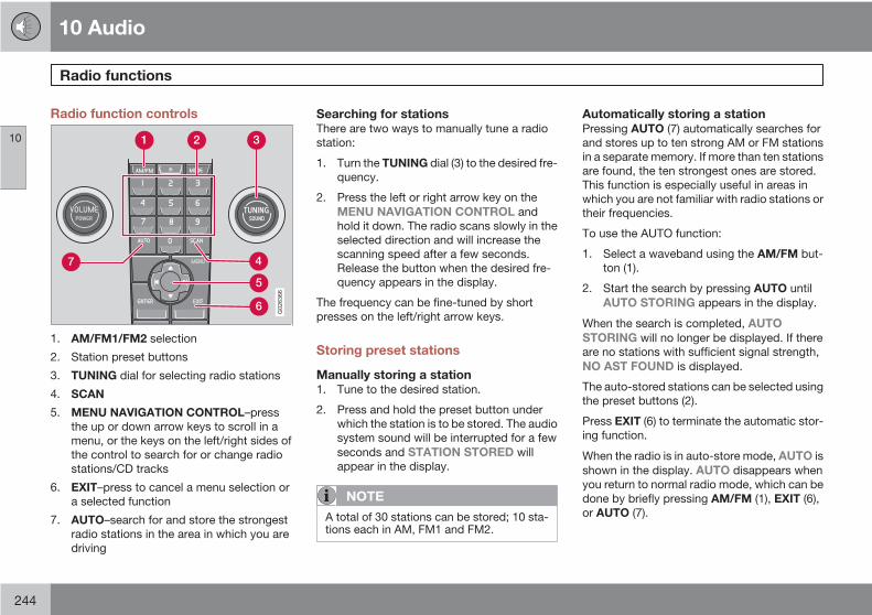
10 Audio
Radio functions
10
244
Radio function controls
G026366
1. AM/FM1/FM2 selection
2. Station preset buttons
3. TUNING dial for selecting radio stations
4. SCAN
5. MENU NAVIGATION CONTROL–pressthe up or down arrow keys to scroll in amenu, or the keys on the left/right sides ofthe control to search for or change radiostations/CD tracks
6. EXIT–press to cancel a menu selection ora selected function
7. AUTO–search for and store the strongestradio stations in the area in which you aredriving
Searching for stationsThere are two ways to manually tune a radiostation:
1. Turn the TUNING dial (3) to the desired fre-quency.
2. Press the left or right arrow key on theMENU NAVIGATION CONTROL andhold it down. The radio scans slowly in theselected direction and will increase thescanning speed after a few seconds.Release the button when the desired fre-quency appears in the display.
The frequency can be fine-tuned by shortpresses on the left/right arrow keys.
Storing preset stations
Manually storing a station1. Tune to the desired station.
2. Press and hold the preset button underwhich the station is to be stored. The audiosystem sound will be interrupted for a fewseconds and STATION STORED willappear in the display.
NOTE
A total of 30 stations can be stored; 10 sta-tions each in AM, FM1 and FM2.
Automatically storing a stationPressing AUTO (7) automatically searches forand stores up to ten strong AM or FM stationsin a separate memory. If more than ten stationsare found, the ten strongest ones are stored.This function is especially useful in areas inwhich you are not familiar with radio stations ortheir frequencies.
To use the AUTO function:
1. Select a waveband using the AM/FM but-ton (1).
2. Start the search by pressing AUTO untilAUTO STORING appears in the display.
When the search is completed, AUTOSTORING will no longer be displayed. If thereare no stations with sufficient signal strength,NO AST FOUND is displayed.
The auto-stored stations can be selected usingthe preset buttons (2).
Press EXIT (6) to terminate the automatic stor-ing function.
When the radio is in auto-store mode, AUTO isshown in the display. AUTO disappears whenyou return to normal radio mode, which can bedone by briefly pressing AM/FM (1), EXIT (6),or AUTO (7).

10 Audio
Radio functions
10
245
To return to the Auto-store mode, press theAUTO button briefly and select a stored stationby pressing one of the preset buttons (2).
Saving auto-stored stations in the presetmemoryAn auto-stored station can be saved in thememory for manually preset stations.
1. Press AUTO (7) briefly.> Auto is displayed.
2. Press one of the preset buttons (2) underwhich the station is to be stored. Holddown the button until STATIONSTORED is displayed.
The radio will then exit auto-store mode andthe stored station can be selected by pressingthe preset button.
ScanningSCAN (4) automatically searches through theselected waveband for strong AM or FM sta-tions. When the radio finds a station, that sta-tion will be played for approximately 8 sec-onds, after which scanning resumes.
Activating/deactivating SCAN1. Select radio mode using the AM/FM but-
ton (2).
2. Press SCAN to activate the function.SCAN is shown in the display.
3. Press the SCAN or EXIT button to deacti-vate the scan function and listen to theselected station.
Storing a station found with SCANA station can be stored as a preset while theSCAN function is activated.
• Press one of the preset buttons (2) underwhich the station is to be stored. Holddown the button until STATIONSTORED is displayed.
The SCAN function will be deactivated and thestation can be selected by pressing the presetbutton.
Radio textCertain stations broadcast program informa-tion, which can be shown in the display.
To start this function:
1. Select FM1 or FM2 and press the MENUbutton.
2. Press ENTER.
3. Select RADIOTEXT in the menu and pressENTER.
To deactivate this function, selectRADIOTEXT again and press ENTER.
Listening to satellite radioThe Sirius satellite system consists of a numberof high elevation satellites in geosynchronousorbit.
NOTE
• The digital signals from the Sirius satel-lites are line-of-sight, which means thatphysical obstructions such as bridges,tunnels, etc, may temporarily interferewith signal reception.
• Avoid any obstructions, such as metal-lic objects transported on roof racks orin a ski box, or other antennas that mayimpede signals from the SIRIUS satel-lites.
Selecting Sirius radio mode1. Press Power to switch on the audio system
(see page 244 for information on the stand-ard radio functions).
2. Press the MODE button repeatedly untilSirius 1 or 2 is displayed.
Activating Sirius radio1. Tune to a satellite channel that has no
audio, which means that the channel isunsubscribed and the text "Call 888-539-SIRIUS TO SUBSCRIBE" is displayed
10 Audio
Radio functions
10
246
(see also "Selecting a channel" in the rightcolumn).
2. Call Sirius at 1-888-539-SIRIUS (7474).
3. When asked for the Sirius ID number pressAUTO to display this number. It is alsopossible to retrieve the Sirius ID from theMENU.
4. "UPDATING SUBSCRIPTION" will bedisplayed while the subscription is beingupdated, after which the display will returnto the normal view.
SIRUS ID
The SIRIUS ID is required when contacting theSirius Call Center. It is used to activate youraccount and when making any account trans-actions. The SIRIUS ID is sometimes referredto as the Electronic Serial Number (ESN).
Selecting a channel category1. Select Sirius radio mode as described
above.
2. Press ENTER.
3. Use the up/down arrow keys to scrollthrough the list of categories.
4. Press ENTER or the right arrow key toselect a category.
5. Use the left or right arrow keys to select achannel in the currently chosen category.
6. Press ENTER to listen to a channel.
NOTE
• The category "All" is default, which ena-bles you to scroll through the entire listof available satellite channels.
• The channel categories are automati-cally updated several times a year. Thistakes approximately two minutes andwill interrupt normal broadcasting. Amessage will be displayed while updat-ing is in progress. Information on chan-nel or feature updates is available atwww.sirius.com.
Selecting a channelThere are three ways of tuning in a channel:
• Using the left and right arrow keys
• By turning the tuning control
• Through direct channel entry
Direct channel entryThe Sirius satellite channels are numberedconsecutively throughout all of the categories.To access a channel directly:
1. Press MENU and scroll to "Direct channelentry."
2. Use the numerical keypad to enter thechannel's number.
3. Press ENTER. The radio will tune to thischannel, even if it belongs to a categoryother than the currently selected one.
NOTE
• The numbers of skipped or lockedchannels will not be displayed.
• If a channel is locked, the access codemust be entered before the channel canbe selected. See "Unlocking a channel"on page 247.
Scanning
NOTE
SCAN automatically searches through thelist of satellite channels. see page 245 formore detailed information.
Storing a channel• A long press on one of the number keys
stores the currently tuned channel on thatkey.
• A short press on a number key while theradio is in Sirius 1or 2 mode will tune to the

10 Audio
Radio functions
10
247
preset satellite channel stored on that but-ton, regardless of the currently selectedchannel category.
Song Seek and Song MemoryThe Song Seek and Song Memory functionsprovide both audio and visual notification whenSirius is broadcasting your favorite songs.Song Seek enables you to store the name ofthe song for future advance notification whenthat song is being played. The Song Memoryfeature makes it possible to view all of the cur-rent songs that are stored in memory.
Song memoryUp to ten songs can be saved in the system'smemory.
1. Press MENU.
2. Scroll to "Add song to song mem." andfollow the instructions shown in the dis-play.
If a new song is selected when the memory isfull, you will be prompted to press ENTER todelete the last song on the list.
NOTE
The remaining songs in the list will movedown one position, and the newly addedsong will be placed at the top of the list.
Song seekWhen a satellite radio channel plays one of thesongs stored in the song memory, the listenerwill be alerted by a text message and an audi-ble signal.
• Press ENTER to listen to the song orEXIT to cancel.
To activate/deactivate the song seek function:
1. Press MENU
2. Scroll to "Song seek"
3. Press ENTER to activate or deactivate thefunction.
NOTE
When the song has ended, the radio willremain tuned to the channel on which thesong was played.
Radio textThe text that is displayed about the song thatis currently playing can be changed. Use theAUTO button or the menu to display the Artist,Title, Composer, or switch radio text off.
Advanced settingsThis menu function enables you to make set-tings on certain Sirius satellite radio functions.To access this menu:
1. Press MENU.
2. Scroll to Sirius menu.
3. Select Advanced Sirius settings.
WARNING
Settings should be made when the vehicleis at a standstill.
The following settings can be made in the Sir-ius menu.
• Songs can be added to the song list
• Channel skip settings can be made
• Channel lock settings can be made
• The channel access code can be displayedor changed
• Your Sirius ID can be displayed
Skip optionsThis function is used to remove a channel fromthe list of available channels.
Skip current
1. Select CHANNEL SKIP LIST and pressENTER.

10 Audio
Radio functions
10
248
2. Select a category in the list and pressENTER.
3. Skip channels in the list presented bypressing ENTER or right arrow key.
Unskip all channels
This permanently removes all channels fromthe skip list and makes them available forselection.
Temp. unskip all ch.
This function will temporarily unskip all chan-nels and make them available for selection. Thechannels remain on the skip list and will againbe skipped the next time the ignition isswitched on.
Channel lock
Access to specific channels can be restricted(locked). A locked channel will not provideaudio, song titles, or artist information.
NOTE
All channels are initially unlocked.
Locking a channel1. Select "Sirius ID" in the menu and select
LOCK OPTIONS and press ENTER.
2. Select CHANNEL LOCK LIST and pressENTER
3. Enter the channel access code and pressENTER.
4. Select a category in the list and pressENTER.
5. Lock channels in the list presented bypressing ENTER or right arrow.
The channel is now locked and a checked boxwill be displayed to indicate this. It will be nec-essary to enter the channel access code1 inorder to listen to a locked channel.
Unlocking a channel:A channel's access code1 is required to unlocka channel.
Unlock all channelsThis permanently removes all channels fromthe locked list and makes them available forselection.
Temp. unlock all ch.This function will temporarily unlock all chan-nels and make them available for selection. Thechannels remain on the locked list and willagain be locked the next time the ignition isswitched on.
CHANGE CODEThis function makes it possible to change thechannel access code. The default code is0000.
To change the code:
1. Select CHANGE CODE and pressENTER.
2. Enter the current code and press ENTER.
3. Enter the code and press ENTER.
4. Confirm the new code and press ENTER.
If an incorrect code is entered, the textWRONG CODE! is displayed.
If you have forgotten the access code:
1. Select "SIRIUS ID" in the Sirius settingsmenu and press ENTER.
2. Press and hold the ENTER button for2 seconds.
3. The current code will be displayed.
Your Volvo retailer can also provide you withassistance.
SIRUS IDThis function displays the 12-digit Sirius acti-vation ID.

10 Audio
CD player/CD changer
10
249
CD function controls
G026367
MENU NAVIGATION CONTROL–pressthe up or down arrow keys to scroll in amenu, or the keys on the left/right sides ofthe control to change CD tracks/fast for-ward/back
Buttons for selecting a disc in theoptional CD changer
CD eject button
CD slot
MODE button
TUNING dial for selecting tracks
Playing a CD
Single CD playerStart the CD player by pressing the MODE but-ton (5) and inserting a disc in the slot (4). If thereis already a disc inserted, it will begin to play.
NOTE
If a CD is in the slot when the audio systemis in CD mode, the CD will be played auto-matically.
CD changer
The CD changer can hold up to six discs.1. Start the CD changer by pressing the
MODE button (5).
2. Select an empty position using the 1 – 6buttons or the up/down keys on the MENUNAVIGATION CONTROL. The displayshows which positions are empty.
3. Insert a disc into the slot (4).
NOTE
• Ensure that INSERT DISC is displayedbefore inserting a disc.
• If a CD position in the changer contain-ing a disc is selected, and the audiosystem is in CD mode when it isswitched on, the CD will play automati-cally.
CD eject
Eject from Single CD playerPress the eject button (3) to eject the disc.
Eject from CD changerThis function makes it possible to eject a singledisc, or to eject all of the discs in the changer.
• Press the eject button (3) briefly to eject thedisc that is currently playing.
• A longer press (more than two seconds)starts the process of ejecting all of thediscs in the changer.

10 Audio
CD player/CD changer
10
250
NOTE
• The EJECT ALL function can only beused while the vehicle is at a standstilland will be cancelled if the vehiclebegins to move.
• For reasons of traffic safety, the ejectedCD must be removed within 12 secondsor it will be automatically drawn backinto the slot and the CD player will enterpause mode. Press the CD button torestart the disc.
CD PauseWhen the audio system volume is turned offcompletely, the CD player will pause and willresume playing when the volume is turned upagain.
Audio filesIn addition to playing normal music CDs, theCD player/changer can also play discs con-taining files in mp3 or wma format.
NOTE
Certain discs that are copy protected can-not be read by the player.
When a disc with audio files is inserted in theplayer, the player scans the disc's foldersbefore it begins playing the files. The length of
time that this takes depends on the quality ofthe disc.
Navigating the disc and playing tracksIf a disc with audio files is in the CD player,press ENTER to display a list of folders on thedisc.
Use the up and down arrows in the navigationcontrol (see the illustration on page 249) tomove among the folders on the disc. Audio fileshave the symbol and folders containingthese files have the symbol. PressENTER to play a selected folder or a file.
When the music file has been played, theplayer will continue to play the rest of the filesin the current folder. When all of the files in thefolder have been played, the player will auto-matically go to the next folder and play the filesin it.
Press the left or right arrow key on the naviga-tion control if the entire name of the currenttrack does not fit in the display.
Changing tracksBriefly press the left or right arrow keys on theMENU NAVIGATION CONTROL to skip to theprevious or next track/file.
NOTE
The TUNING dial (6) (turn clockwise to go tothe next track/file, or counterclockwise togo to the previous track/file) or the steeringwheel keypad can also be used for this pur-pose.
Fast forward/backPress and hold down the left or right arrowskeys in the MENU NAVIGATION CONTROL (orthe corresponding keys on the optional steer-ing wheel keypad) to search within a track/fileor the whole disc. The search continues for aslong as the buttons are held down.
Random playThis function plays the tracks/files on a CD (oron all of the CDs if the vehicle is equipped withthe optional CD changer) in random order(shuffle).
Activating/deactivating the randomfunction-CD player
If a normal CD is being played:1. Press MENU followed by ENTER.
2. Select Random and press ENTER.
If a CD with audio files is being played:1. Press MENU followed by ENTER.
2. Select Random and press ENTER.

10 Audio
CD player/CD changer
10
251
3. Select Disc or Folder and press ENTER.
Activating/deactivating the randomfunction-CD changer
If a normal CD is being played:1. Press MENU followed by ENTER.
2. Select Random and press ENTER.
3. Select Single disc or All discs and pressENTER.
If a CD with audio files is being played:1. Press MENU followed by ENTER.
2. Select Random and press ENTER.
3. Select Single disc or Folder and pressENTER.
NOTE
CD changer only–you can only select thenext random track/file on the current disc.
Press the EXIT button to stop random play.The random function is automatically deacti-vated when another disc is selected.
Disc text (CD changer only)Certain CDs contain information about thedisc, such as the titles of the tracks, etc. Thisinformation can be shown in the display byactivating the DISC TEXT function.
1. Press MENU. Select the menu for relevantsound source and press ENTER.
2. Select Disc text in the menu and pressENTER.> If information is stored on the disc, it will
now appear in the display.
To deactivate this function, select Disc text inthe menu and press ENTER.
ScanThis function plays the first 10 seconds of eachtrack/file on the CD.
• Press SCAN.
• Press EXIT or SCAN to stop the scan func-tion and listen to an entire track/file.
CD eject
Single CD playerPress the eject button (3) to eject the disc.
CD changerThis function makes it possible to eject a singledisc, or to eject all of the discs in the changer.
• Press the eject button (3) briefly to eject thedisc that is currently playing.
• A longer press (more than two seconds)starts the process of ejecting all of thediscs in the changer.
NOTE
• The Eject all function can only be usedwhile the vehicle is at a standstill and willbe cancelled if the vehicle begins tomove.
• For reasons of traffic safety, the ejectedCD must be removed within 12 secondsor it will be automatically drawn backinto the slot and the CD player will enterpause mode. Press the CD button torestart the disc.
Compact disc careKeep the following in mind when playing/han-dling compact discs
• Do not put tape or labels on the disc itself.They could become stuck in the player.
• CDR discs can cause listening problemsdue to the quality of the disc or recordingequipment used.
• DualDisc: The audio side of a DualDisc(combined CD/DVD) does not meet CDspecifications and may not play in youraudio system.
• Keep the discs clean. Wipe them with asoft, clean, lint-free cloth, working from thecenter outward. If necessary, dampen thecloth with a neutral soap solution. Dry thor-oughly before using.

10 Audio
CD player/CD changer
10
252
• Never use cleaning spray or antistatic liq-uid. Use only cleaners specifically made forCDs.
• Use discs of the correct size only (3.5"discs should never be used).
• Volvo does not recommend the use ofplastic outer rings on the disc.
• Condensation may occur on discs/opticalcomponents of the changer in cold winterweather. The disc can be dried with aclean, lint-free cloth. Optical componentsin the CD changer may, however, take upto one hour to dry off.
• Never attempt to play a damaged CD.
• When not in use, the discs should bestored in their covers. Avoid storing discsin excessive heat, direct sunlight or industy locations.
10 Audio
Audio menu
10
253
FM1/FM2 menu1. RADIOTEXT ON/OFF
2. ADVANCED RADIO SETTINGS
3. AUDIO SETTINGS
AM menu1. AUDIO SETTINGS
CD menu1. RANDOM
2. AUDIO SETTINGS
CD changer menu1. RANDOM
2. DISC TEXT ON/OFF
3. AUDIO SETTINGS
AUX menu1. AUX VOLUME
2. SOUND SETTINGS

10 Audio
Bluetooth hands-free connection
10
254
Introduction
G029503
System overview
Cell phone
Location of the microphone
Center console control panel and display
Bluetooth hands-freeThis option makes it possible to set up a wire-less connection between a Bluetooth-enabledcell phone and the vehicle’s audio system. Thisenables the audio system to function as ahands-free connection and allows you toremote-control a number of the phone’s func-tions. The microphone used by this system islocated in the ceiling console (2). The buttons
and other controls on the cell phone canalways be used regardless of whether or notthe phone is connected to the hands-free sys-tem.
NOTE
Not all cell phones are fully compatible withthe hands-free system. A list of compatiblephones is available at your Volvo retailer orat www.volvocars.com
WARNING
Never use the hands-free feature or anyother device in your vehicle in a way thatdistracts you from the task of driving safely.Distraction can lead to a serious accident.
Getting startedUse the controls in the center console (3) toaccess, navigate and make selections in thehands-free system’s menus (see page 258).
Activating/deactivatingA short press on the PHONE button in the cen-ter console activates the hands-free system.The text TELEPHONE will appear at the top ofthe display to indicate that the audio system isin telephone mode.
The symbol indicates that the hands-freesystem is active.
A long press on the PHONE button deactivatesthe hands-free system and disconnects thecell phone.
Connecting cell phonesThe procedure for connecting a cell phone var-ies, depending on the phone itself, and onwhether or not the phone has been previouslyconnected.
If this is the first time the phone is to be con-nected to the hands-free system, proceed asfollows:
Alternative 1–using the vehicle's menus
1. Activate the cell phone’s Bluetooth func-tion (refer to the phone’s owner’s manual ifnecessary) or go to www.volvocars.com
2. Activate the vehicle’s Bluetooth hands-free system by briefly pressing thePHONE button.> Add phone will be displayed. If one or
more cell phones are already registeredin the system, they will also be dis-played.
3. Select Add phone.
10 Audio
Bluetooth hands-free connection
10
255
> The audio system will search for cellphones that are in range. This searchtakes approximately 30 seconds. Anyphones detected will be displayed withtheir Bluetooth names. The hands-freesystem’s Bluetooth name will appearin the cell phone’s display as My Car.
4. Select one of the cell phones shown in theaudio system’s (center console) display.
5. Using the cell phone’s keypad, enter thedigits shown in the audio system’s display.
Alternative 2–using the cell phone’s menus
1. Activate the hands-free system by brieflypressing the PHONE button in the centerconsole. If there is a cell phone connected,disconnect it from the hands-free system(by pressing PHONE in the center consolefor several seconds).
2. Perform a search using the cell phone’sBluetooth function (consult the cellphone’s owner’s manual if necessary).
3. Select My Car in the list of devices shownin the cell phone’s display.
4. When prompted, enter the PIN code 1234in the cell phone.
5. Connect to My Car from the cell phone.
The cell phone will be registered and will beconnected automatically to the audio systemwhile the text Synchronising is displayed. Formore information on synchronizing a cellphone, see page 257.
When a connection has been established, the symbol and the cell phone’s Bluetooth
name will be displayed. The cell phone cannow be controlled from the audio system.
Making a call1. Ensure that TELEPHONE is shown at the
top of the center console display and thatthe symbol is visible (by pressing brieflyon PHONE on the center console).
2. Dial the desired phone number or use thephone book (see page 257).
3. Press ENTER.
End the call by pressing EXIT.
Disconnecting the cell phoneThe cell phone is automatically disconnectedfrom the audio system if it is moved out ofrange. For more information about connec-tions, see page 254.
The cell phone can be manually disconnectedfrom the hands-free system by pressingPHONE. The hands-free system is also deac-tivated when the ignition is switched off (or if
the driver’s door is opened on vehicles equip-ped with the optional keyless drive).
When the cell phone is disconnected from thehands-free system, a call in progress can becontinued using the cell phone’s own speakerand microphone.
NOTE
Certain cell phones may require confirma-tion from the phone’s keypad when a call istransferred from hands-free to the cellphone.
Handling calls
Incoming callsPress ENTER to answer a call, even if the audiosystem is currently in e.g., CD or FM mode.Press EXIT to defer a call.
Automatic answerThis function means that incoming calls will beanswered automatically. Activate or deactivatethe function in the menu system under Phonesettings Call options Automaticanswer.

10 Audio
Bluetooth hands-free connection
10
256
Call settingsWhile a call is in progress, press MENU orENTER on the center console to access thefollowing functions:
• Microphone off–mute the audio system’smicrophone.
• Transfer call to mobile–transfer the callfrom hands-free to the cell phone.
• Phone book–this feature enables you tosearch for a stored telephone number.
NOTE
• On certain cell phones, the connectionis broken when the mute function isused, which is normal. If this happens,the hands-free system will prompt youto reconnect.
• A new call cannot be initiated whileanother call is in progress.
Sound settings
Call volumeCall volume can be adjusted when the hands-free system is activated. Use the buttons in thesteering wheel keypad or the audio system’svolume control.
Audio system volumeWhile a phone call is in progress, volume forthe audio system can be adjusted in the normalway with the audio system's volume control. Inorder to adjust volume during a phone call, theaudio system must be switched to one of theother modes (FM, CD, etc).
Audio system sound can be automaticallymuted when a phone call is received in Phonesettings Sounds and volume Muteradio and adjust the volume with the / keys on the center console.
Ringing volumeGo to Phone settings Sounds and volume
Ring volume and adjust the volume withthe / keys on the center console.
Ringing tonesThe hands-free system’s integrated ringingtones can be selected in Phone settings
Sounds and volume Ring signal Ringsignal 1,2,3....
NOTE
The connected cell phone’s ring tone is notswitched off when one of the hands-freesystem's ringing tones is used.
If you prefer to use the connected cell phone’sring tone1, go to Phone settings Soundsand volume Ring signal Use mobilephone signal
More information about registeringand connecting cell phonesA maximum of 5 cell phones can be registeredin the hands-free system. Registration onlyneeds to be done once for each phone. Afterregistration, the cell phone no longer needs tobe in sight or searchable. Only one cell phonecan be connected to hands-free at a time.Phones can be unregistered in BluetoothRemove telephone
Automatic connectionWhen the hands-free system is active and themost recently connected cell phone is withinrange, it is detected automatically. When the
1 Not supported by all cell phones

10 Audio
Bluetooth hands-free connection
10
257
audio system searches for the most recentlyconnected phone, this phone’s name appearsin the display. To manually connect a differentcell phone, press EXIT.
Manual connectionTo connect a phone other than the one thatwas most recently connected or to switchbetween cell phones that are already regis-tered in the hands-free system:
1. Put the audio system in telephone mode.2. Press PHONE in the center console and
select one of the phones on the list.
A connection can also be established in themenu system under Bluetooth Connectphone or Change phone.
Phone bookIn order to use the hands-free system’s phonebook (list of contacts), TELEPHONE must bedisplayed at the top of the center console dis-play and the symbol must be visible.
The audio system stores a copy of the phonebook of each registered cell phone. The phonebook is automatically copied each time aphone is connected. This function can be acti-vated in Phone settings Synchronisephone book. Searches for contacts are only
made in the phone book of the currently con-nected cell phone.
NOTE
If a particular cell phone does not supportcopying of the phone book, List is emptywill be displayed when copying has beencompleted.
If the phone book contains information aboutsomeone who is trying to call you, this infor-mation will be shown in the display.
Searching for contactsThe easiest way to search for a contact in thephone book is to press and hold any of thebuttons 2–9. This starts a search based on thefirst letter on the button that has been pressed.
The phone book can also be accessed bypressing the navigation buttons / on thecenter console or by pressing / on thesteering wheel keypad. A search can also bemade in the phone book’s search menu inPhone book Search:
1. Enter the first letter of the contact’s nameand press ENTER or simply press ENTER.
2. Select the desired contact and pressENTER to make a call to that person.
Voice controlIf the cell phone that is currently connectedallows calls to be made via voice commands,this function can be used by pressing and hold-ing ENTER.
Voice mail numberThe phone number to your voice mail can bechanged in the menu Phone settings Calloptions Voice mail number. If no numberhas been stored, this menu can be accessedby a prolonged press on button 1. Once aphone number has been stored, press and hold1 to dial this number.
Call listsLists of calls in a particular cell phone are cop-ied to the hands-free system each time thatphone is connected. These lists are then upda-ted while the phone is connected. PressENTER to show the most recently dialed num-bers. Other call lists can be found under Callregister.
NOTE
Certain cell phones display the list of themost recently dialed numbers in reverseorder.

10 Audio
Bluetooth hands-free connection
10
258
Entering textText is entered by using the number buttons inthe center console. Press a button once toenter the first letter on the button, twice to enterthe second letter, etc. Continue to press thebutton to display other characters.
Press EXIT briefly to erase a character. Pressand hold EXIT to erase all of the characters thathave been entered. Use the / buttons onthe center console to navigate among the char-acters.
Button Function
Space .1-? ! , : " ' ( )
A B C 2 Ä Å À Æ Ç
D E F 3 È É
G H I 4 Ì
J K L 5
M N O 6 Ñ Ö Ò Ø
P Q R S 7 ß
Button Function
T U V 8 Ü Ù
W X Y Z 9
Press briefly if two characters areto be entered in succession fromthe same button.
+ 0 @ * # & $ £ / %
Shift between uppercase andlowercase letters
Bluetooth menus1. Missed calls
2. Received calls
3 Dialed calls
4. Phone book
4.1. Search
4.2. Copy fr. mobile phone
5. Bluetooth...
5.1. Change phone
5.2. Connect phone
5.3. Disconnect phone
5.4. Connect fr. mobile phone
6. Phone settings
6.1. Call options
6.1.2. Automatic answer
6.1.3. Voice mail number
6.2. Sounds and volume
6.3. IDIS
6.4. Synchronize phone book

10 Audio
10
259

G000000
260
Label information.................................................................................. 262Dimensions and weights....................................................................... 264Fuel, oils, and fluids.............................................................................. 267Engine oil............................................................................................... 269Engine specifications............................................................................ 270Electrical system................................................................................... 272Three-way catalytic converter............................................................... 274Volvo programs..................................................................................... 275
11SPECIF ICATIONS
11 Specifications
Label information
11
262
G03
2545
G02
6511

11 Specifications
Label information
11
263
Model plateVehicle Identification Number (VIN). Codes forcolor and upholstery, etc.
Federal Motor Vehicle SafetyStandards (FMVSS) specifications (USA)and Ministry of Transport (CMVSS)standards (Canada)Your Volvo is designed to meet all applicablesafety standards, as evidenced by the certifi-cation label on the facing side of the driver'sdoor. For further information regarding theseregulations, please consult your Volvo retailer.
Loads and Tire PressuresThe appearance of the decal will vary, depend-ing on the market for which the vehicle isintended.
Canadian models have the upper decal
U.S. models have the lower decal.
Vehicle Identification Number (VIN)1
The VIN plate is located on the top left surfaceof the dashboard. The VIN is also stamped onthe right hand door pillar.
Vehicle Emission Control InformationYour Volvo is designed to meet all applicableemission standards, as evidenced by the cer-
tification label on the underside of the hood.For further information regarding these regula-tions, please consult your Volvo retailer.
1 The Vehicle Identification Number (VIN) should always be quoted in correspondence concerning your vehicle with the retailer and when ordering parts.

11 Specifications
Dimensions and weights
11
264
Dimensions
G017205
Position Dimension in. (mm)
A Wheelbase 103.9 in. (264 cm)
B Length 177.7 in. (451 cm)
C Load length, floor, seatback down 69.7 in. (177 cm)
D Load length, floor 39 in. (99 cm)
E Height 57.2 in. (145 cm)
F Track, front 60.4 in. (154 cm)
G Track, rear 60.3 in. (153 cm)

11 Specifications
Dimensions and weights
11
265
Position Dimension in. (mm)
H Width 69.7 in. (177 cm)
I Width encl. door mirrors 79.6 in. (202 cm)
Weights
Category USA Canada
Gross vehicle weight FWDA: 4320 lbs
FWD Turbo: 4320 lbs
AWDB Turbo: 4450 lbs
1960 kg
1960 kg
2020 kg
Capacity weight FWD: 800 lbs
AWD: 800 lbs
365 kg
365 kg
Permissible axle weight, front FWD: 2380 lbs
FWD Turbo: 2380 lbs
AWD Turbo: 2420 lbs
1080 kg
1080 kg
1100 kg
Permissible axle weight, rear FWD: 2220 lbs
FWD Turbo: 2220 lbs
AWD Turbo AWD: 2220 lbs
1010 kg
1010 kg
1010 kg
Curb weight FWD: 3265–3345 lbs
AWD: 3470–3500 lbs
1450–1515 kg
1565–1590 kg
Max. roof load All models: 165 lbs All models: 75 kg

11 Specifications
Dimensions and weights
11
266
Category USA Canada
Max. trailer weight (w/o brakes)C All models: 1540 lbs All models: 700 kg
Max. trailer weight (with brakes) All models: 2000 lbs All models: 900 kg
Max. tongue weight All models: 165 lbs All models: 75 kg
A FWD = Front Wheel DriveB AWD = All Wheel DriveC Models equipped with the B5244S7 engine (engine code 39, which is the 6th and 7th digits from the left in your vehicle's VIN number, see chapter Label information, for the location of the VIN plate),
may not be used to tow trailers or vehicles of any kind. This could cause damage to the vehicle's emission control systems.
CAUTION
The maximum permissible axle loads and/or the gross vehicle weight must not beexceeded.
WARNING
When adding accessories, equipment, lug-gage and other cargo to your vehicle, thetotal capacity weight must not be exceeded.

11 Specifications
Fuel, oils, and fluids
11
267
Specifications and capacities
Category Specification Capacity
Fuel tank Octane rating: unleaded gasoline, minimumoctane requirement AKI 87, recommended rat-ing AKI 91 or above.
15.9 US gallons (60 liters)
Models with All Wheel Drive have a tank volumeof 15 US gallons (57 liters).
Models with engine code 39 have a fuel tankcapacity of 14 US gallons (53 liters). This codeis the 6th and 7th digits from the left in yourvehicle's VIN number. see page 262 for thelocation of the VIN plate.
Engine oil (with filter replacement) See page 269 for information on engine oilspecifications.
6.1 US quarts (5.8 liters)
Automatic transmission oil Non-turbo engine: JWS 3309 8.19 US quarts (7.75 liters)
Manual transmission oil BOT 130 5-speed: 2.2 US quarts (2.1 liters)
6-speed: 2.1 US quarts (2.0 liters) – turbo mod-els
Coolant Volvo original coolant/antifreeze (50/50 mixtureof water and anti-freeze)
10.5 US quarts (10 liters) – models with auto-matic transmission
10 US quarts (9.5 liters) – models with manualtransmission
Brake fluid DOT 4+ boiling point >536 °F (280 °C), P/N9437433
0.63 US quarts (0.6 liters)
Power steering fluid WSS M2C204-A or equivalent 1.3 US quarts (1.2 liters) – system and reservoircombined

11 Specifications
Fuel, oils, and fluids
11
268
Category Specification Capacity
Washer fluid reservoir Use washer fluid solvent in cold weather con-ditions.
6.8 US quarts (6.5 liters)
Air conditioning system Refrigerant – R134a 1.2 lbs. (530 grams)
NOTE
The transmission oil does not normally needto be changed during the service life of thevehicle. However, it may be necessary toreplace the oil if the vehicle is often drivenin areas of sustained temperature extremes(hot or cold), when towing a trailer over longdistances, for prolonged driving in moun-tainous areas, or if the vehicle is often drivenshort distances in temperatures under 40 °F(5 °C).
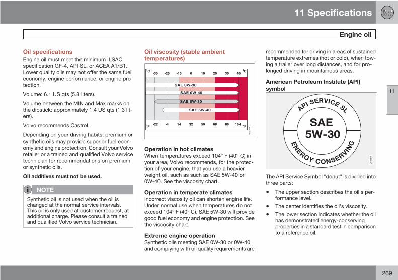
11 Specifications
Engine oil
11
269
Oil specificationsEngine oil must meet the minimum ILSACspecification GF-4, API SL, or ACEA A1/B1.Lower quality oils may not offer the same fueleconomy, engine performance, or engine pro-tection.
Volume: 6.1 US qts (5.8 liters).
Volume between the MIN and Max marks onthe dipstick: approximately 1.4 US qts (1.3 lit-ers).
Volvo recommends Castrol.
Depending on your driving habits, premium orsynthetic oils may provide superior fuel econ-omy and engine protection. Consult your Volvoretailer or a trained and qualified Volvo servicetechnician for recommendations on premiumor synthetic oils.
Oil additives must not be used.
NOTE
Synthetic oil is not used when the oil ischanged at the normal service intervals.This oil is only used at customer request, atadditional charge. Please consult a trainedand qualified Volvo service technician.
Oil viscosity (stable ambienttemperatures)
G02
3491
Operation in hot climatesWhen temperatures exceed 104° F (40° C) inyour area, Volvo recommends, for the protec-tion of your engine, that you use a heavierweight oil, such as such as SAE 5W-40 or0W-40. See the viscosity chart.
Operation in temperate climatesIncorrect viscosity oil can shorten engine life.Under normal use when temperatures do notexceed 104° F (40° C), SAE 5W-30 will providegood fuel economy and engine protection. Seethe viscosity chart.
Extreme engine operationSynthetic oils meeting SAE 0W-30 or 0W-40and complying with oil quality requirements are
recommended for driving in areas of sustainedtemperature extremes (hot or cold), when tow-ing a trailer over long distances, and for pro-longed driving in mountainous areas.
American Petroleum Institute (API)symbol
G02
2917
The API Service Symbol "donut" is divided intothree parts:
• The upper section describes the oil's per-formance level.
• The center identifies the oil's viscosity.
• The lower section indicates whether the oilhas demonstrated energy-conservingproperties in a standard test in comparisonto a reference oil.
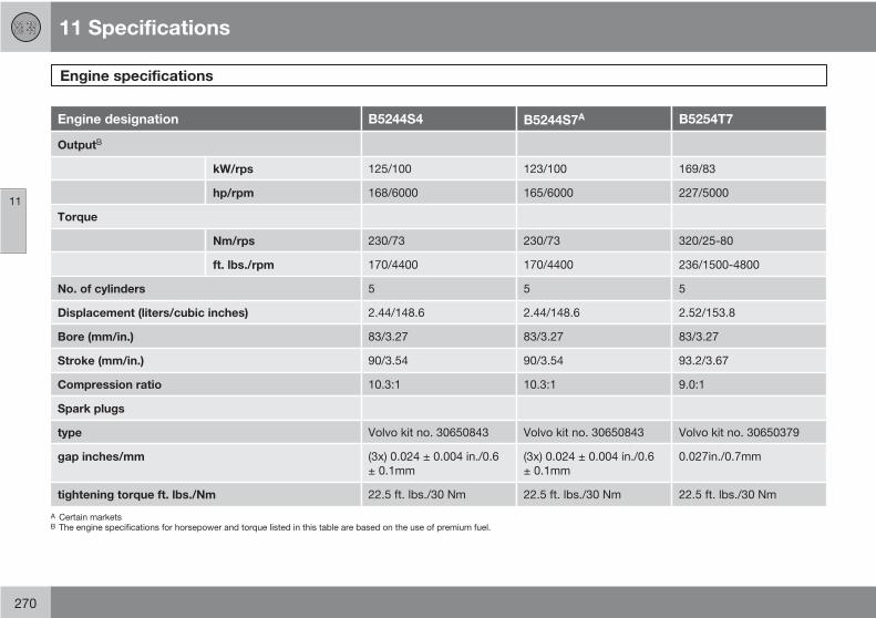
11 Specifications
Engine specifications
11
270
Engine designation B5244S4 B5244S7A B5254T7
OutputB
kW/rps 125/100 123/100 169/83
hp/rpm 168/6000 165/6000 227/5000
Torque
Nm/rps 230/73 230/73 320/25-80
ft. lbs./rpm 170/4400 170/4400 236/1500-4800
No. of cylinders 5 5 5
Displacement (liters/cubic inches) 2.44/148.6 2.44/148.6 2.52/153.8
Bore (mm/in.) 83/3.27 83/3.27 83/3.27
Stroke (mm/in.) 90/3.54 90/3.54 93.2/3.67
Compression ratio 10.3:1 10.3:1 9.0:1
Spark plugs
type Volvo kit no. 30650843 Volvo kit no. 30650843 Volvo kit no. 30650379
gap inches/mm (3x) 0.024 ± 0.004 in./0.6± 0.1mm
(3x) 0.024 ± 0.004 in./0.6± 0.1mm
0.027in./0.7mm
tightening torque ft. lbs./Nm 22.5 ft. lbs./30 Nm 22.5 ft. lbs./30 Nm 22.5 ft. lbs./30 Nm
A Certain marketsB The engine specifications for horsepower and torque listed in this table are based on the use of premium fuel.
11 Specifications
Engine specifications
11
271
Charge air cooler (Intercooler)Turbocharged engines employ a turbo-com-pressor to force air into the engine inlet mani-fold and a charge air cooler to cool thecompressed inlet air. The resulting increase inair flow raises pressure in the intake manifoldand increases engine power over that devel-oped by the normally-aspirated engine. Thecharge air cooler (which resembles a radiator)is located between the turbo-compressor andinlet manifold.
Fuel systemThe engine is equipped with a multiport fuelinjection system.

11 Specifications
Electrical system
11
272
General information12-volt system with voltage controlled gener-ator. Single wire system in which the chassisand engine block are used as conductors,grounded on the chassis.
Battery
Voltage 12 V 12 V
Cold startcapacity(CCA)
600 AA 700 AB
Reservecapacity(RC)
120 min 135 min
Capacity(Ah)
70 80
A Models equipped with the High Performance audio systemB Models equipped with the Premium Sound audio system,
the Volvo Navigation System and/or keyless drive
If the battery must be replaced, replace it withone with the same cold start capacity andreserve capacity as the original (see the decalon the battery).
WARNING
PROPOSITION 65 WARNING!
Battery posts, terminals, and related acces-sories contain lead and lead compounds,chemicals known to the state of Californiato cause cancer and reproductive harm.Wash hands after handling.
Bulbs used in the car
Bulb Output Type
Low beam headlight 55W H7
High beam headlight (applies to vehicles with halogen headlights) 55W H9

11 Specifications
Electrical system
11
273
Bulb Output Type
Extra high beam (models with Active Bi-Xenon headlights only) 55W H7
Brake light, back-up light, rear fog light 21W P21W
Turn signal, front/rear (applies to models with halogen headlights) 21W PY21W
Turn signal, front/rear (models with Active Bi-Xenon headlights) 24W P21/5W
Rear parking light, side marker light 5W P21/W5
Footwell lighting, cargo compartment light, license plate lighting 5W C5W
Vanity mirror 1.2W Festoon
Front parking light, side turn signal 5W W5W
Front fog light (option) 35W H8
Glove compartment light 3W Festoon
NOTE
For information regarding any other bulbsnot mentioned in this section, please con-tact your Volvo retailer or a trained andauthorized Volvo service technician.

11 Specifications
Three-way catalytic converter
11
274
Three-way catalytic converter –general information• Keep your engine properly tuned. Certain
engine malfunctions, particularly involvingthe electrical, fuel or distributor ignitionsystems, may cause unusually high three-way catalytic converter temperatures. Donot continue to operate your vehicle if youdetect engine misfire, noticeable loss ofpower or other unusual operating condi-tions, such as engine overheating or back-firing. A properly tuned engine will helpavoid malfunctions that could damage thethree-way catalytic converter.
• Do not park your vehicle over combustiblematerials, such as grass or leaves, whichcan come into contact with the hot exhaustsystem and cause such materials to igniteunder certain wind and weather condi-tions.
• Excessive starter cranking (in excess ofone minute), or an intermittently firing orflooded engine can cause three-way cata-lytic converter or exhaust system over-heating.
• Remember that tampering or unauthorizedmodifications to the engine, the ElectronicControl Module, or the vehicle may be ille-gal and can cause three-way catalytic con-verter or exhaust system overheating. Thisincludes:
NOTE
Unleaded fuel is required for vehicles withthree-way catalytic converters.
11 Specifications
Volvo programs
11
275
Volvo On Call Roadside AssistanceYour new Volvo comes with a four year ONCALL roadside assistance. Additional informa-tion, features, and benefits are described in aseparate information package in your glovecompartment.
If you require assistance, dial:
American customers: 1-800-638-6586(1-800-63-VOLVO)
Canadian customers: 1-800-263-0475
Technician certificationIn addition to Volvo factory training, Volvo sup-ports certification by the National Institute forAutomotive Service Excellence (A.S.E.). Certi-fied technicians have demonstrated a highdegree of competence in specific areas.Besides passing exams, each technician mustalso have worked in the field for two or moreyears before a certificate is issued. These pro-fessional technicians are best able to analyzevehicle problems and perform the necessarymaintenance procedures to keep your Volvo atpeak operating condition.

12 Index
12
276
1, 2, 3 ...
12-volt sockets.......................................... 60
A
A/C (air conditioning)................................. 90
ABS (anti-lock brake system).................. 153
Active Bi-Xenon headlights........................ 61
Airbagsfront...................................................... 22inflatable curtain................................... 30side impact........................................... 29
Airbag system............................................ 22
Air conditioning.......................................... 90
Air distribution table................................... 99
Air vents..................................................... 92
Alarm system........................................... 130turning off sensors.............................. 131
All Wheel Drive......................................... 152
Anti-lock Brake System (ABS)................. 153
Approach lighting....................................... 83
Audio files................................................ 250
Audio systemaudio functions................................... 240automatic sound control..................... 243AUX port............................................. 240CD changer......................................... 249CD player/changer.............................. 249compact disc care.............................. 251Dolby Surround Pro Logic II............... 243equalizer............................................. 243menu settings..................................... 253radio functions.................................... 244selecting a sound source.................... 240Sirius satellite radio............................ 245sound settings.................................... 242steering wheel keypad........................ 241storing radio stations.......................... 244subwoofer........................................... 242USB/iPOD connector.......................... 241
Auto-dim rearview mirror........................... 77
Autolock..................................................... 82
Automatic locking retractor....................... 35
Automatic sound control......................... 243
Automatic transmission........................... 149kickdown............................................ 150oil........................................................ 267shiftlock override................................ 151
Automatic transmission - Geartronic....... 150
AUX port.................................................. 240
Axle weight...................................... 183, 265
B
Backrest, rear seat, folding...................... 111
Bass......................................................... 242
Batterymaintenance....................................... 221remote control, replacing................... 120specifications...................................... 272warning symbols................................. 221
Battery – replacing................................... 221
Bi-Xenon headlights.................................. 61
Black Box (Vehicle Event Data)............... 210
Blind Spot Information System (BLIS)..... 164
Booster cushionaccessory............................................. 41
Brake fluid........................................ 219, 267
Brake lights................................................ 62
Brake systemanti-lock brakes (ABS)........................ 153emergency brake assistance.............. 154
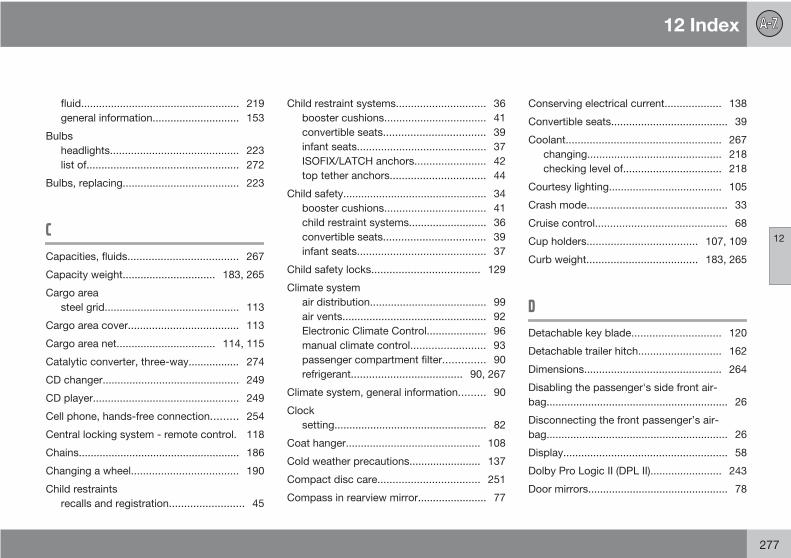
12 Index
12
277
fluid..................................................... 219general information............................. 153
Bulbsheadlights........................................... 223list of................................................... 272
Bulbs, replacing....................................... 223
C
Capacities, fluids..................................... 267
Capacity weight............................... 183, 265
Cargo areasteel grid............................................. 113
Cargo area cover..................................... 113
Cargo area net................................. 114, 115
Catalytic converter, three-way................. 274
CD changer.............................................. 249
CD player................................................. 249
Cell phone, hands-free connection......... 254
Central locking system - remote control. 118
Chains...................................................... 186
Changing a wheel.................................... 190
Child restraintsrecalls and registration......................... 45
Child restraint systems.............................. 36booster cushions.................................. 41convertible seats.................................. 39infant seats........................................... 37ISOFIX/LATCH anchors........................ 42top tether anchors................................ 44
Child safety................................................ 34booster cushions.................................. 41child restraint systems.......................... 36convertible seats.................................. 39infant seats........................................... 37
Child safety locks.................................... 129
Climate systemair distribution....................................... 99air vents................................................ 92Electronic Climate Control.................... 96manual climate control......................... 93passenger compartment filter.............. 90refrigerant..................................... 90, 267
Climate system, general information......... 90
Clocksetting................................................... 82
Coat hanger............................................. 108
Cold weather precautions........................ 137
Compact disc care.................................. 251
Compass in rearview mirror....................... 77
Conserving electrical current................... 138
Convertible seats....................................... 39
Coolant.................................................... 267changing............................................. 218checking level of................................. 218
Courtesy lighting...................................... 105
Crash mode............................................... 33
Cruise control............................................ 68
Cup holders..................................... 107, 109
Curb weight..................................... 183, 265
D
Detachable key blade.............................. 120
Detachable trailer hitch............................ 162
Dimensions.............................................. 264
Disabling the passenger's side front air-bag............................................................. 26
Disconnecting the front passenger’s air-bag............................................................. 26
Display....................................................... 58
Dolby Pro Logic II (DPL II)........................ 243
Door mirrors............................................... 78
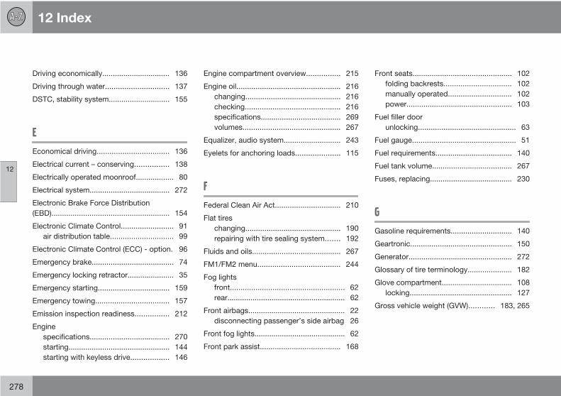
12 Index
12
278
Driving economically................................ 136
Driving through water.............................. 137
DSTC, stability system............................. 155
E
Economical driving.................................. 136
Electrical current – conserving................ 138
Electrically operated moonroof.................. 80
Electrical system...................................... 272
Electronic Brake Force Distribution(EBD)........................................................ 154
Electronic Climate Control......................... 91air distribution table.............................. 99
Electronic Climate Control (ECC) - option. 96
Emergency brake....................................... 74
Emergency locking retractor...................... 35
Emergency starting.................................. 159
Emergency towing................................... 157
Emission inspection readiness................ 212
Enginespecifications...................................... 270starting................................................ 144starting with keyless drive.................. 146
Engine compartment overview................ 215
Engine oil................................................. 216changing............................................. 216checking............................................. 216specifications...................................... 269volumes.............................................. 267
Equalizer, audio system........................... 243
Eyelets for anchoring loads..................... 115
F
Federal Clean Air Act............................... 210
Flat tireschanging............................................. 190repairing with tire sealing system....... 192
Fluids and oils.......................................... 267
FM1/FM2 menu....................................... 244
Fog lightsfront...................................................... 62rear........................................................ 62
Front airbags.............................................. 22disconnecting passenger’s side airbag 26
Front fog lights........................................... 62
Front park assist...................................... 168
Front seats............................................... 102folding backrests................................ 102manually operated.............................. 102power.................................................. 103
Fuel filler doorunlocking.............................................. 63
Fuel gauge................................................. 51
Fuel requirements.................................... 140
Fuel tank volume...................................... 267
Fuses, replacing....................................... 230
G
Gasoline requirements............................. 140
Geartronic................................................ 150
Generator................................................. 272
Glossary of tire terminology..................... 182
Glove compartment................................. 108locking................................................ 127
Gross vehicle weight (GVW)............ 183, 265

12 Index
12
279
H
Hand brake (parking brake)....................... 74
Hands-free connection (cell phone) (Cellphone, hands-free connection)................ 254
Hazard warning flashers............................ 73
Headlights.................................................. 61Active Bi-Xenon (option)....................... 61changing bulbs................................... 223high and low beams............................. 64high beam flash.................................... 64
Headlight washers..................................... 70
Head restraints, rear seat........................ 111
High beam flash......................................... 64
High beams................................................ 64
Home safe lighting............................... 64, 83
Hood, opening......................................... 214
I
Ignition switch.......................................... 143
Immobilizer.............................................. 144
Immobilizer (start inhibitor)...................... 118
Indicator and warning symbols............ 51, 53
Infant seats................................................ 37
Inflatable Curtain........................................ 30
Inflation pressure..................................... 176
Inflation pressure, checking..................... 177
Inflation pressure tableCanadian models................................ 179US models.......................................... 178
Information display.............................. 51, 58messages in.......................................... 58
Information symbol.................................... 53
Inspection, preparing for......................... 212
Inspection readiness................................ 212
Instrument overview.................................. 48
Instrument panel.................................. 48, 51
Instrument panel lighting........................... 62
Interior lighting......................................... 105
iPOD connector (audio system)............... 241
ISOFIX/LATCH anchors............................. 42
J
Jacket hanger.......................................... 108
Jump starting........................................... 159
K
Key blade......................................... 120, 124
Keyless drivelocation of antennas (pacemaker warn-ing)...................................................... 125locking and unlocking the vehicle...... 123power seat memory............................ 124starting the engine.............................. 146
Keylock.................................................... 144
Kickdown................................................. 150
L
Label information..................................... 262
LATCH (ISOFIX) anchors........................... 42
Lighting panel............................................ 61
Load anchoring eyelets........................... 115
Loading the vehicleroof loads............................................ 163
Lockingfrom the inside.................................... 127glove compartment............................. 127
Locking the vehicle.................................. 123
Locks, child safety................................... 129

12 Index
12
280
Long distance trips.................................. 138
Lug nuts (wheel nuts)............................... 188
M
Maintenance............................................ 210performed by the owner..................... 212
Manual climate control.............................. 93
Manual transmission........................ 147, 148
Mirrors.................................................. 77, 78
Model plate.............................................. 263
Moonroof................................................... 80
Motor oil........................................... 216, 269checking............................................. 216
N
Net in cargo area............................. 114, 115
O
Occupant safety........................................ 16
Occupant weight sensor............................ 26
Octane recommendations....................... 140
Oil............................................................. 216changing............................................. 216checking............................................. 216
On Call Roadside Assistance.................. 275
Opening the hood.................................... 214
Owner maintenance................................. 212
P
Panel lighting, instrument.......................... 62
Park assist............................................... 168
Parking brake............................................. 74
Parking lights............................................. 61
Passenger’s side front airbag, disabling. . . 26
Periodic owner-performed maintenance. 212
Permissible axle weight........................... 183
Personal settings....................................... 82
Power door mirrors.................................... 78
Power front seat...................................... 103memory function................................. 103
Power moonroof........................................ 80
Power steering fluid................................. 219
Power windows......................................... 75
Pregnancy, using seat belts during........... 19
R
RadioSirius satellite radio............................ 245
Radio functions........................................ 244
Rain sensor - windshield wipers................ 71
Rear fog light............................................. 62
Rear park assist....................................... 168
Rear seat backrests, folding down.......... 111
Rear seatscenter head restraint........................... 111
Rearview mirror.......................................... 77auto-dim function................................. 77
Rearview mirror with compass (option)..... 77
Recalls, child restraints.............................. 45
Refrigerant (A/C system).................... 90, 267
Refueling.................................................. 142fuel tank volume................................. 267
Registering child restraints........................ 45
Remote control........................................ 118battery replacement............................ 120

12 Index
12
281
functions............................................. 118key blade............................................ 120
Replacing fuses....................................... 230
Reporting safety defectsCanada................................................. 17USA....................................................... 16
Roof loads................................................ 163
Rotating tires........................................... 189
S
Safety, occupant........................................ 16
Safety defects, reportingCanada................................................. 17USA....................................................... 16
Safety locks, child.................................... 129
Seat beltreminder................................................ 19
Seat belts................................................... 18Automatic locking retractor/Emergencylocking retractor.................................... 35buckling................................................ 18maintenance......................................... 20pretensioners........................................ 18
unbuckling............................................ 18use during pregnancy........................... 19
Seats, front.............................................. 102
Shiftlockoverride............................................... 151
Side door mirrors....................................... 78
Side impact airbags................................... 29
Side impact protection (SIPS) airbags....... 29
Sirius satellite radio.................................. 245
Snow chains............................................ 186
Snow tires................................................ 186
Sound control, automatic........................ 243
Sound settings, audio system................. 242
Spare tire................................................. 187
Stability system........................................ 155Dynamic Stability Traction Control(DSTC)................................................ 155
Starting the engine................................... 144with keyless drive............................... 146
Start inhibitor (immobilizer).............. 118, 144
STC, stability system............................... 155
Steering wheeladjusting............................................... 73keypad................................................ 241
Storage compartments............................ 107
Studded tires........................................... 186
Subwoofer............................................... 242
Sunroof (moonroof).................................... 80
Supplemental restraint system.................. 21
T
Tachometer................................................ 51
Tailgate wipers................................... 71, 220
Telephone (cellular), hands-free connec-tion (Cell phone, hands-free connection). 254
Temporary spare tire............................... 187
Three-way catalytic converter................. 274
Tire inflation............................................. 176
Tire inflation pressureCanadian models................................ 179US models.......................................... 178
Tire Pressure Monitoring System (TPMS) 197
Tires......................................................... 174age...................................................... 175changing............................................. 190changing from summer to winter........ 189designations....................................... 180

12 Index
12
282
glossary of terms................................ 182improving economy............................ 175inflation............................................... 176inflation pressure, checking................ 177inflation pressure table, Canadian mod-els....................................................... 179inflation pressure table, US models.... 178load ratings......................................... 177rotation............................................... 189snow................................................... 186spare................................................... 187speed ratings...................................... 177storing................................................. 174studded............................................... 186tire pressure monitoring system......... 197tire sealing system.............................. 192tread wear indicator............................ 175uniform tire quality grading................. 185winter driving...................................... 186
Tire sealing system.................................. 192
Top tether anchors (child restraint sys-tems).......................................................... 44
Towing a trailer........................................ 160trailer hitch.......................................... 162
Towing the vehicle................................... 157
Trailer hitch - detachable......................... 162
Trailer towing........................................... 160
TransmissionGeartronic........................................... 150manual........................................ 147, 148shiftlock override................................ 151
Tread wear indicator................................ 175
Treble....................................................... 242
Trip computer............................................ 66
Trips, long distance................................. 138
Turn signals............................................... 64indicator lights...................................... 51
U
Uniform Tire Quality Grading................... 185
V
Vehicle dimensions.................................. 264
Vehicle Event Data................................... 210
Vehicle loading......................................... 183roof loads............................................ 163
Vehicle maintenanceperformed by the owner..................... 212
Vehicle towing.......................................... 157
Vehicle weights........................................ 265
VIN (Vehicle Identification Number)......... 263
Volvo Inflatable Curtain.............................. 30
Volvo On Call Roadside Assistance........ 275
W
Warning flashers, hazard........................... 73
Warning symbol......................................... 53
Warranties................................................ 210
Washer fluid..................................... 218, 267
Washer fluid reservoir...................... 215, 218
Water, driving through............................. 137
Weights.................................................... 265
Wheel nuts............................................... 188
Wheels..................................................... 174changing............................................. 190storing................................................. 174
Whiplash Protection System (WHIPS)....... 31
Windowspower.................................................... 75
Windshield washer fluid reservoir............ 215
Windshield wiper blades.......................... 220

12 Index
12
283
Windshield wipers...................................... 70rains sensor.......................................... 71
Winter tires............................................... 186
Wiper bladesreplacing tailgate wiper...................... 220replacing windshield wipers............... 220

12 Index
12
284


