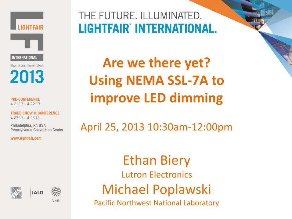
Are we there yet? Using NEMA SSL‐7A to improve LED dimming
April 25, 2013 10:30am-12:00pm
Ethan BieryLutron Electronics
Michael PoplawskiPacific Northwest National Laboratory
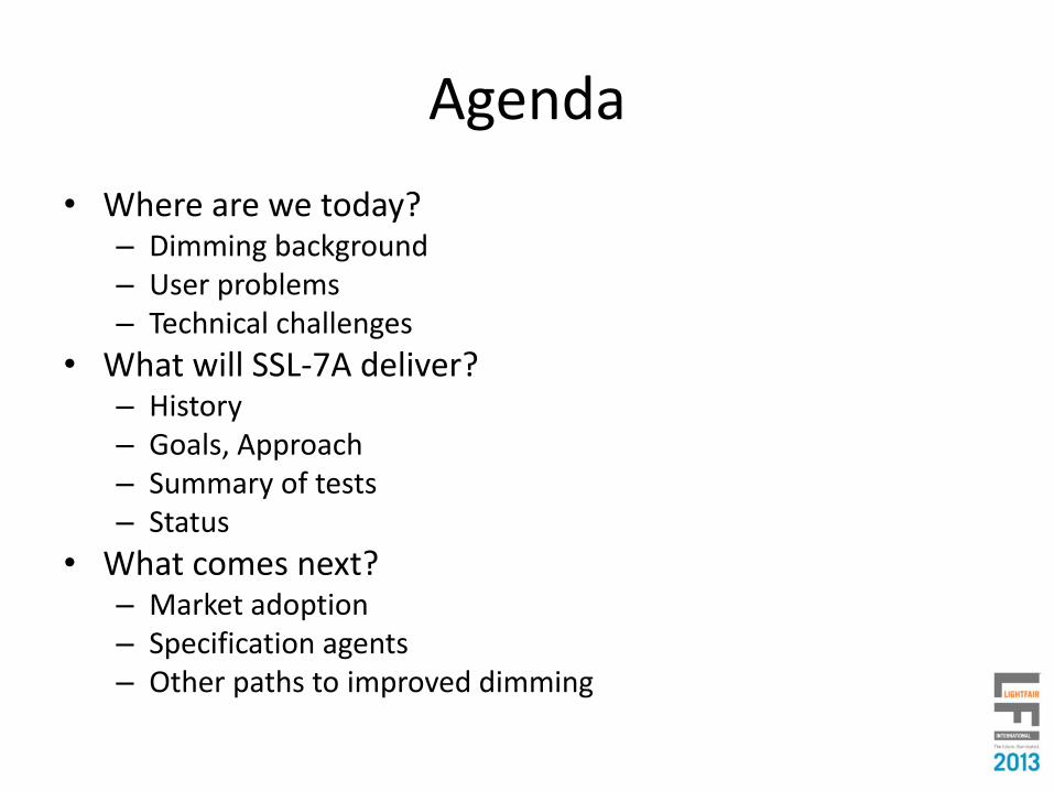
Agenda
• Where are we today?– Dimming background– User problems– Technical challenges
• What will SSL-7A deliver?– History– Goals, Approach– Summary of tests– Status
• What comes next?– Market adoption– Specification agents– Other paths to improved dimming

WHERE ARE WE AT TODAY?

Two approaches to dimming
• Coincident AC power and control signal– Reduce amplitude of AC sine
wave
– Phase-cut AC sine wave
• Separate AC power and control signal– Wiring requirements
– Degree of device-level control
– One or two-way communication
AC Power
AC Power

Common dimming technologies
• Coincident AC power and control signal– Sine wave (long obsolete)– Phase-Cut
• Forward phase or reverse phase• 2-Wire or 3-Wire
• Separate AC power and control signal– Fluorescent 3-Wire– 0-10V– DALI– DMX512
AC Power
AC Power
Hot
Hot
Neutral
Neutral
Neutral
DimmedHot
DimmedHotAC
Power

Forward phase-cut dimming
• Most common dimming method
• Largest (by far) installed base
• Designed for resistive (incandescent, halogen) or magnetic low-voltage (MLV) loads
• Typically a TRIAC switching device, but may use Field-Effect Transistors (FETs)
• Low cost, simple designs
0 90 180 270 3600 90 180 270 3600 90 180 270 360

Forward phase-cut dimmer examples
RFI Element
Timing Element
TRIAC
Hot
Dimmed
Hot
“Advanced features”
RFI Element
Timing Element
TRIAC
Hot
Dimmed
Hot
“Advanced features”
RFI Element
Timing Element
TRIAC
Hot
Dimmed
Hot
Neutral
BasicIncandescent Dimmer
Dimmer with “Advanced Features”
Dimmerwith Neutral
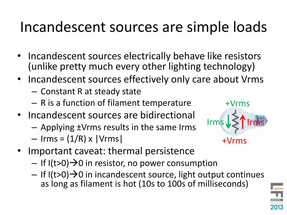
Incandescent sources are simple loads
• Incandescent sources electrically behave like resistors (unlike pretty much every other lighting technology)
• Incandescent sources effectively only care about Vrms– Constant R at steady state – R is a function of filament temperature
• Incandescent sources are bidirectional– Applying ±Vrms results in the same Irms– Irms = (1/R) x |Vrms|
• Important caveat: thermal persistence– If I(t>0)0 in resistor, no power consumption– If I(t>0)0 in incandescent source, light output continues
as long as filament is hot (10s to 100s of milliseconds)
+Vrms
+Vrms
Irms Irms

Controlling incandescent light output
Vrms = 120V
Vrms = 120V
Vrms = 120V
Vrms = 120V
Vrms = 120V Vrms = 60V 50% light output
Same(average) light
output
High performanceInexpensiveVrms adjusterDetermines dimming performance!

LEDs are complex loads
• LEDs are non-linear devices– Different current-voltage relationships in
different regions of operation
– Small change in voltage can equal large change in current
– (Average) current must (typically) be controlled
• LEDs are unidirectional– (Forward) current only flows in one direction
– Light output only produced for forward current
• Important caveat: fast response– If I(t>0)0 in diode, no power consumption
– If I(t>0)0 in LED, no light output
– Careful attention to time where I≈0
+Vled>Vth
+Vled>Vth
Iled I≈0
Vled
I led

LEDs (typically) need a Driver
• Non-linear Iled vs. Vled relationship, together with manufacturing variation in Vf, mean LEDs are best regulated by controlling their current
• Typically, LEDs are operated (or “Driven”) such that their (average) current is constant (Constant Current)
• Typically, power electronics components are used to create circuits which convert AC voltage into regulated LED constant (average) current
Black BoxVrms = 120VCCAC
Power

Controlling LED light output
Different(average)
light output
Controls current to LED
Black Box
High performanceInexpensiveVrms adjuster
Determines dimming performance!
Vrms = 120V
Vrms = 120V
Vrms = 120V
Vrms = 120V
Vrms = 120V Vrms = 60V

Shouldn’t LED dimming be easy?
• Variation in LED system architecture, driver design matter– LED lighting is still very much an emerging technology– Significant market variation today, likely for the foreseeable future– Lagging focus on dimmability (dimmable or designed to dim?)
• Variation in dimmer architecture, circuit design matter– Existing infrastructure was predominantly designed to dim
incandescent sources– Cost, expectation barrier to replacing dimming controls
• No standards for ensuring LED dimming compatibility or predictable performance– Standard measurement procedures or metrics for dimming
compatibility or dimming performance have never existed– Some existing standards are not as “standard” as one would expect or
desire
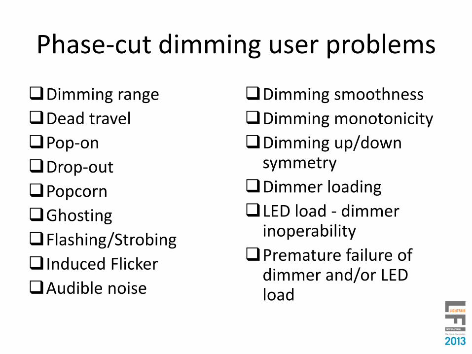
Phase-cut dimming user problems
Dimming range
Dead travel
Pop-on
Drop-out
Popcorn
Ghosting
Flashing/Strobing
Induced Flicker
Audible noise
Dimming smoothness
Dimming monotonicity
Dimming up/down symmetry
Dimmer loading
LED load - dimmer inoperability
Premature failure of dimmer and/or LED load

Dimming range, dead travel, pop-on
Source: Modified from NEMA SSL-6
Switched output

Dimming smoothness, monotonicity, up/down symmetry
Source: Modified from NEMA SSL-6
Switched output
Up/down
asymmetry

Induced flicker
~50% dimmer ~25% dimmer ~0% dimmer
Switch 100% dimmer ~75% dimmer

Dimmer loading
• Minimum load varies by dimmer
• Maximum load varies by dimmer and LED loadDimmer Light Source Possible loading
600W incandescent 60W incandescent 1-10
600W incandescent 12W LED 1-50?
600W ELV 50W halogen 1-12
600W ELV 10W LED 1-60?
3-10*
2-30*
*Example; varies by LED load

Other problems
• Drop-out– No light output at the bottom of the dimming range
– The light source turns off when the switch is still on
• Popcorn– Different turn-on times for different light sources on a
dimmed circuit
• Ghosting– The light source is at a low-level on state when it should be
off
• Flashing/Strobing– The light source is intermittently on when it should be off

Not the desired effect

Phase-cut dimmingtechnical challenges
LED load RMS current
LED load inrush current
LED load repetitive peak current
Repetitive ring-up voltage
Dimmer switching element current requirements
Dimmer timing element series impedance requirements
Dimmer on-state and/or off-state operating current requirements

• RMS current of an LED load may not immediately decrease as it is dimmed; a 20%-50% increase is not uncommon
0 mA
20 mA
40 mA
60 mA
80 mA
100 mA
120 mA
140 mA
160 mA
180 mA
Maximum MinimumLight Level
Inp
ut
RM
S C
urr
en
t
LED load RMS current
Max Irms
Incandescent dimming curve
LEDdimming curve

LED load RMS current
• Higher current in control can cause excessive (unexpected) heating of components in control or LED load
• Excessive heating can cause component stress and premature failure
• Increased power and energy consumption– If at any point during dimming Irms has gone up
more than Vrms has gone down …
– Then Pave = Irms x Vrms can go up!

LED load inrush current
• Created by connection to power
• Occurs once per power-up
Inrush Current
Turn on Current
Voltage
I peak = 104A!
LED load: 36W, 120Vrms, 0.3 Arms
Phase-cut voltage
Input Current

LED load inrush current
• Excessive wear on switch or relay contacts• Premature failure (welding) of switch or relay• Large chokes can be designed into dimmer to
minimize inrush to dimmer, but may create issues of their own
Relay contacts120VAC, 16A
50k cycles
Mechanical and electrical wear
(high inrush)
Primarily mechanical wear (no inrush)

LED load repetitive peak current
• Created by forward phase-cut, occurs every half-cycle
• Commonly 5-10x Irms; can be much higher
Repetitive Peak Current
Dimmer at 50% light level
LED Current
Resistive Current
Voltage
50% Conduction Angle
Phase-cut voltage
LED load: 15W, 120 Vrms, 0.13 Arms
I peak = 3.75A
LED load current

LED load repetitive peak current
• Varies significantly across LED products
• Often major factor determining maximum dimmer loading
• Major contributor to audible noise in light sources and controls
• Major contributor to RFI noise and interference with other electronics
• Major contributor to potentially reduced control lifetime

Repetitive ring-up voltage
• A very brief spike in voltage (above the instantaneous line voltage) caused by the discharge of energy-storage elements
• Can cause long-term damage to voltage-sensitive components in the dimmer or lamp
• Caused by interaction between dimmer and lamp
Voltage across LED load
V peak = 225V
LED load: 6W, 120 Vrms, 0.05 Arms

Dimmer switching element requirements
Cu
rren
t
30mA
-30mA
Incandescent
LED
TRIAC Minimum
TRIAC dropout for LED load

Dimmer timing element requirements
• The timing element for phase-cut dimmers without neutral are designed to operate through the load, and expect “resistive” load characteristics
• LED load input impedance characteristics are typically not resistive, and may change as it is dimmed.
Dimmer
Hot
Neutral
Timing Circuit
Timing circuitin series with load

Dimmer timing element requirements
• Timing element problems cause the switching element to turn on or off at the wrong time, aperiodically (not at consistent intervals), or both
• Any change in the switching element behavior directly affects light output– Turning on or off at wrong time will raise or lower
light level
– Turning on or off aperiodically causes the light level to change from cycle to cycle, likely resulting in objectionable flicker

Dimmer “advanced features” requirements
• Dimmers without neutral need to use LED load for return path to keep “advanced features” circuitry running
• Most LED loads can not pass standby current required by dimmers with advanced features
DimmerHot
Neutral
Night Light
Small current flow through the load even when dimmer is “off”

Neutral benefits
• Dimmers with neutral have a path other than through the load for timing circuit or “advanced features” current
Requires neutral wire in backbox!
Dimmer
Hot
Neutral
TimingCircuit
No current through the load when the dimmer is off

Dimmer operating current requirements
• Can lead to LED source flashing/strobing– LED source gets/accepts enough current to start, but
not maintain operation
• Can lead to LED source ghosting– LED source gets/accepts enough current to start, and
maintain (low light level) operation
• Can lead to dimmer inoperability or malfunction– LED source does not accept enough current to
maintain proper operation of the dimmer control
– Most problematic for advanced dimmers
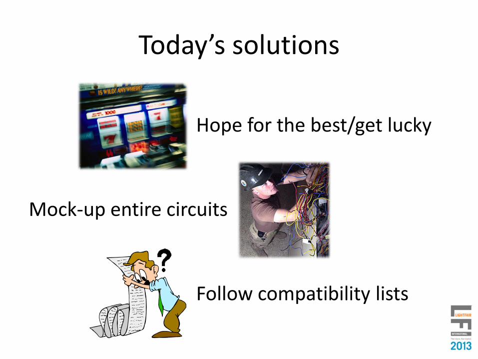
Today’s solutions
Hope for the best/get lucky
Mock-up entire circuits
Follow compatibility lists

WHAT WILL SSL-7A DELIVER?
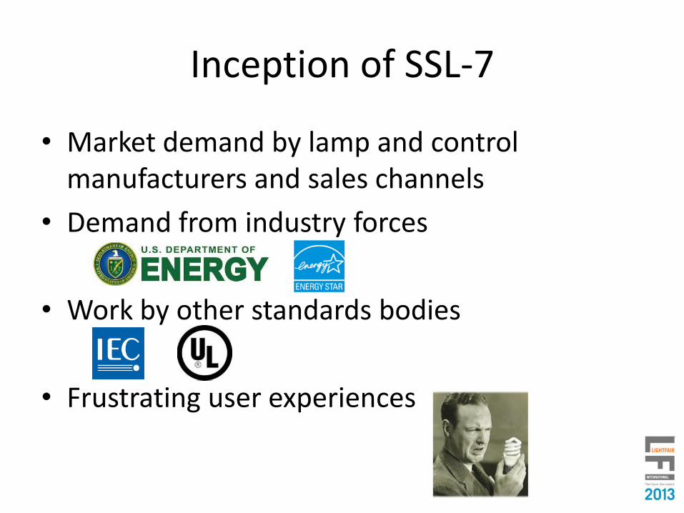
Inception of SSL-7
• Market demand by lamp and control manufacturers and sales channels
• Demand from industry forces
• Work by other standards bodies
• Frustrating user experiences

Inception of SSL-7
• Zhaga’s goal of “interchangeable LED Light Engines” required control compatibility
• No common standardization of control type (forward/reverse phase) or specification existed
• NEMA was chosen as the administrative body for developing a phase-control specification
• SSL-7 is expected to be required by Zhaga-compliant products which use phase-cut dimming

Inception of SSL-7
• Existing SSL 6 (2010) described installed base of phase-cut dimmers
• Latent demand for a tighter specification
• A forward-looking strategy was adopted to bound the problem:– NOT concerned with existing
products (variation is too wide)
– Expected to be used on newproducts going forward
Source: http://www.nema.org/standards/Pages/Solid-State-Lighting-for-Incandescent-Replacement-Dimming.aspx

Who was involved
• A consortium open to many interested companies
• NEMA Lighting Section members– American lamp and control manufacturers
• Plus other members– Standards bodies, European manufacturers, IC
manufactures (invited through Zhaga)
• Multi-national group targeted a global scope– 100, 120, 230, 277V specifications

SSL-7 requirements
• In late 2011, work began within NEMA on SSL-7, using basic requirements defined by Zhaga as a starting point
• Scope of work and existing obstacles were identified in order to achieve a rapid specification
• Goal is that the NEMA document will be accepted as a whole or in part by standards-enforcement bodies (Zhaga, UL, Energy Star, IEC, etc.)
– NEMA does not enforce standards

PerformanceCompatibility
• SSL7 is an interface standard: it specifies the interaction between lamps and dimmers
• The problem is very complicated! So, the strategy was to break it into two aspects:
Compatibility Performance
SSL7 Overview
Premature Failure
Dimming Curve
Audible Noise
Popcorn
Dead Travel
Flicker
Predictable Outcome

Basic definitions
• Dimmer– A device (with or without a neutral wire) which
creates a forward-phase waveform
• LLE (LED Light Engine)– A combination of an LED module plus driver, either
combined (lamp) or separate (fixture)
• Compatible– Reliability of the dimmer and LLE are not affected by
combining them– Dimming behavior meets or exceeds specified
functionality

Structure of SSL7
• Addresses it as a system components:
– Dimmer section
– LLE section
• Two unknown black boxes need to work together, each which has wide variation

SSL7 Test philosophy
• Synthetic test circuits are used to generate proper characteristics or waveforms for testing the Device Under Test (DUT: LLE or Dimmer)
• Components in Test Circuits are usually adjusted for:– Power rating of Dimmer/LLE being tested– Mains voltage of DUT
• If the DUT works with the synthetic circuit, representing a worst-case scenario, it will work with any device whose characteristics do not exceed that worst-case

Summary of tests
Dimmer Tests
Waveform stability
Inrush
Repetitive Peak Current
Overload
Repetitive Ringup Voltage
Min. Conduction Angle
Max. Conduction Angle
Off-state Current
On-state Current
LLE Tests
Inrush
Repetitive Peak Current
Maximum RMS Current
Repetitive Ringup Voltage
Minimum Light Level
Maximum Light Level
Off-state Current
On-state Current

“Low Power Factor”Synthetic Load
(defined in SSL7)Defined Power Source
Examine waveform
0 90 180 270 360
• Purpose: ensure Dimmer provides a proper (stable) forward-phase-cut waveform
• Test: connect Dimmer to two Synthetic Loads, representing high-power factor and low-power factor LLE (two different kinds of worst-case scenarios)
Dimmer section: Stability
“High Power Factor”Synthetic Load
(defined in SSL7)

Dimmer section: Inrush
• Purpose: ensure Dimmer can handle high-inrush loads well
• Test: connect Dimmer to Low Power Factor Synthetic Load, representing worst-case LLE
“Low Power Factor”Synthetic Load
(defined in SSL7)Defined Power Source
Manufacturer confirms reliability

LLE section: Inrush
• Purpose: ensure LLE does not generate excessive inrush current
• Test: connect LLE to Inrush Generator, representing worst-case switch-on scenario
Inrush Generator (defined in SSL7)
Defined Power Source
Measure waveform
peak

Dimmer section:Repetitive peak current
• Purpose: ensure Dimmer can handle high repetitive peak current
• Test: connect Dimmer to Low Power Factor Synthetic Load, representing worst-case LLE
“Low Power Factor”Synthetic Load
(defined in SSL7)Defined Power Source
Manufacturer confirms reliability

LLE section: Repetitive peak current
• Purpose: ensure LLE does not generate excessive repetitive peak current
• Test: connect LLE to Synthetic Waveform Generator, simulating a forward-phase dimmer
Defined Power Source
Measure waveform
peakForward-Phase Waveform Generator
(defined in SSL7)

Dimmer section: Overload
• Purpose: ensure Dimmer can handle increased RMS current that may occur when dimming some LLEs
• Test: connect Dimmer to Low Power Factor Synthetic Load, representing worst-case LLE
“Low Power Factor”Synthetic Load
(defined in SSL7)Defined Power Source
Manufacturer confirms reliability
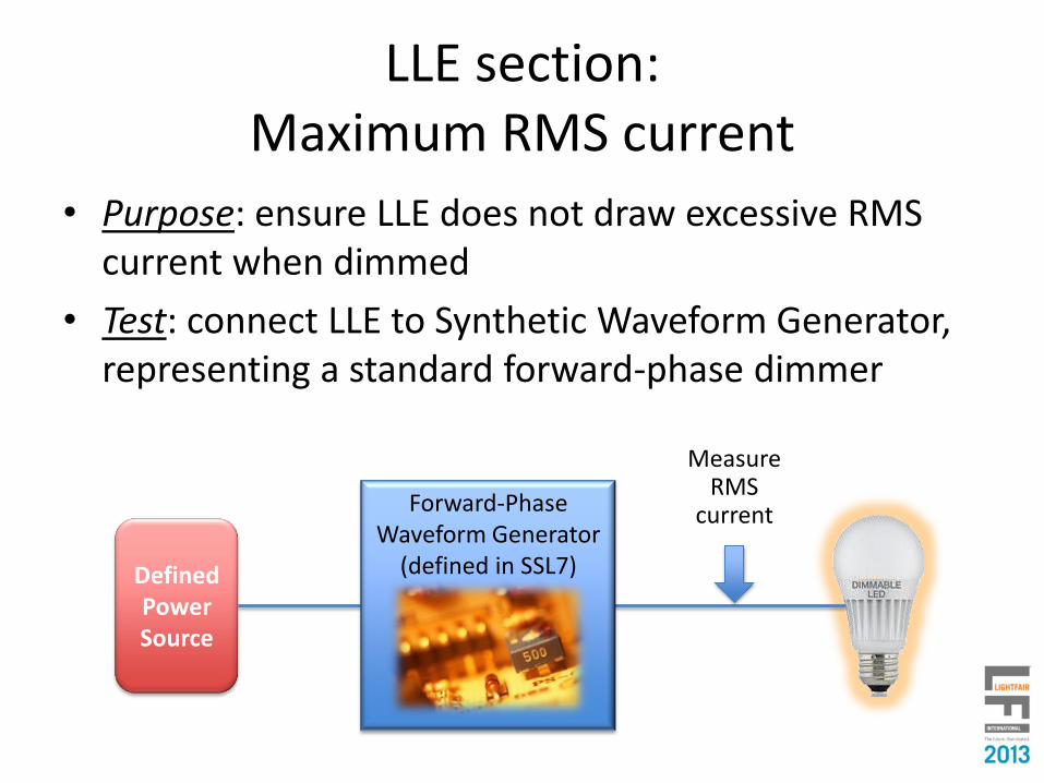
LLE section:Maximum RMS current
• Purpose: ensure LLE does not draw excessive RMS current when dimmed
• Test: connect LLE to Synthetic Waveform Generator, representing a standard forward-phase dimmer
Defined Power Source
Measure RMS
currentForward-Phase Waveform Generator
(defined in SSL7)
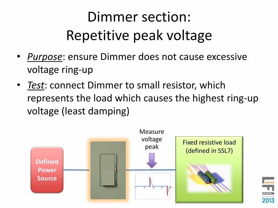
Dimmer section:Repetitive peak voltage
• Purpose: ensure Dimmer does not cause excessive voltage ring-up
• Test: connect Dimmer to small resistor, which represents the load which causes the highest ring-up voltage (least damping)
Defined Power Source
Measure voltage
peak
0 90 180 270 360
Fixed resistive load (defined in SSL7)

LLE section:Repetitive peak voltage
• Purpose: ensure LLE does not cause excessive voltage ring-up
• Test: connect LLE to Synthetic Waveform Generator, representing a standard forward-phase dimmer
Measure voltage
peak
0 90 180 270 360
Defined Power Source
Forward-Phase Waveform Generator
(defined in SSL7)

Dimmer section:Min/Max conduction angle
• Purpose: ensure Dimmer can produce the proper expected range of conduction angles under all conditions
• Test: connect Dimmer to High Power Factor Synthetic Load, representing a worst-case LLE
Defined Power Source
Measure conduction
angle
0 90 180 270 360
“High Power Factor”Synthetic Load
(defined in SSL7)

• Purpose: ensure LLE goes to expected light level when given waveforms that represent high end and low end
• Test: connect LLE to Synthetic Waveform Generator, representing a standard forward-phase dimmer
Defined Power Source
Forward-Phase Waveform Generator
(defined in SSL7)
Measure light level
LLE section: Min/Max light level

Voltage across LLE
Dimmer supply current in the off-state
• Test must confirm Dimmer can get enough current through LLE in order to operate, without adversely affecting LLE
ᵔᴗVoltage across dimmer
+ -
+-
Power Supply
Current
Mains Voltage
Available power to dimmer

Dimmer section: Off-state current
• Purpose: ensure Dimmer power supply can operate without drawing excessively high peak currents over a defined LLE impedance range
• Test: connect Dimmer to variable resistive load, representing a range of possible LLE designs
Defined Power Source
Measure peak
currentVariable resistive load

LLE section: Off-state current
• Purpose: ensure LLE can allow required amount of current for Dimmer power supply to operate
• Test: connect LLE to Synthetic Power Supply representing a worst-case (constant power) power supply; power supply must generate specified voltage (draw sufficient power)
Constant Power Load(defined in SSL7)
Measure proper voltage
Defined Power Source

Dimmer supply current in the on-state
• Dimmer can only get power when its switching device (triac, etc.) is not conducting
• Hardest to do at high end: least amount of time when dimmer is conducting
ᵔᴗVoltage across dimmer
Voltage across LLE
+ -
+-
Current
Mains Voltage
Power Supply
Available power to dimmer
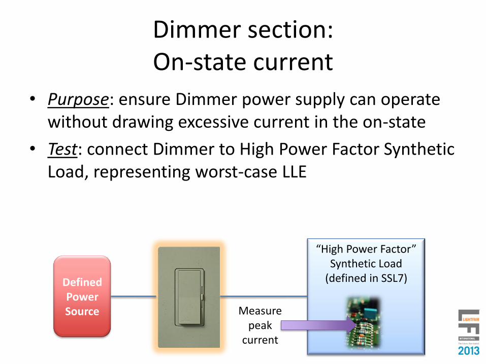
Dimmer section: On-state current
• Purpose: ensure Dimmer power supply can operate without drawing excessive current in the on-state
• Test: connect Dimmer to High Power Factor Synthetic Load, representing worst-case LLE
Defined Power Source Measure
peak current
“High Power Factor”Synthetic Load
(defined in SSL7)

LLE section: On-state current
• Purpose: ensure LLE allows sufficient current for Dimmer power supply to operate
• Test: connect LLE to Synthetic Power Supply representing a worst-case (constant power) power supply; power supply must generate specified voltage (draw sufficient power)
Constant Power Load(defined in SSL7)
Measure proper voltage
Defined Power Source

• Not all dimmers need a large amount of current for on-and off-state operation
• Not all lamps want to include the additional complexity for dimmers whose power supply requires high current
On and off-state current challenges

“Universal”LLE
Type 1 and Type 2Dimmers and LLEs
LLE
Type 1 Type 2
Dim
me
r Type 1
Type 2May work withmultiple LLEs
“Universal”Dimmer

Marking requirements
Dimmer
• Maximum rated wattage
• Minimum load
• Type 1/Type 2 compliance
• How to set SSL-7A load type
LLE
• Minimum light output
• Type 1/Type 2 compliance

So how did we do?User problems:
Dimming range
Dead travel
Pop-on
Drop-out
Popcorn
Ghosting
Flashing/Strobing
Induced Flicker
Audible noise
Dimming smoothness
Dimming monotonicity
Dimming up/down symmetry
Dimmer loading
LED load - dimmer inoperability
Premature failure of dimmer and/or LED load

So how did we do?Technical challenges
LED load RMS Current
LED load inrush Current
LED load repetitive peak current
Repetitive ring-up voltage
Dimmer switching element current requirements
Dimmer timing element series impedance requirements
Dimmer on-state and/or off-state operating current requirements
Status
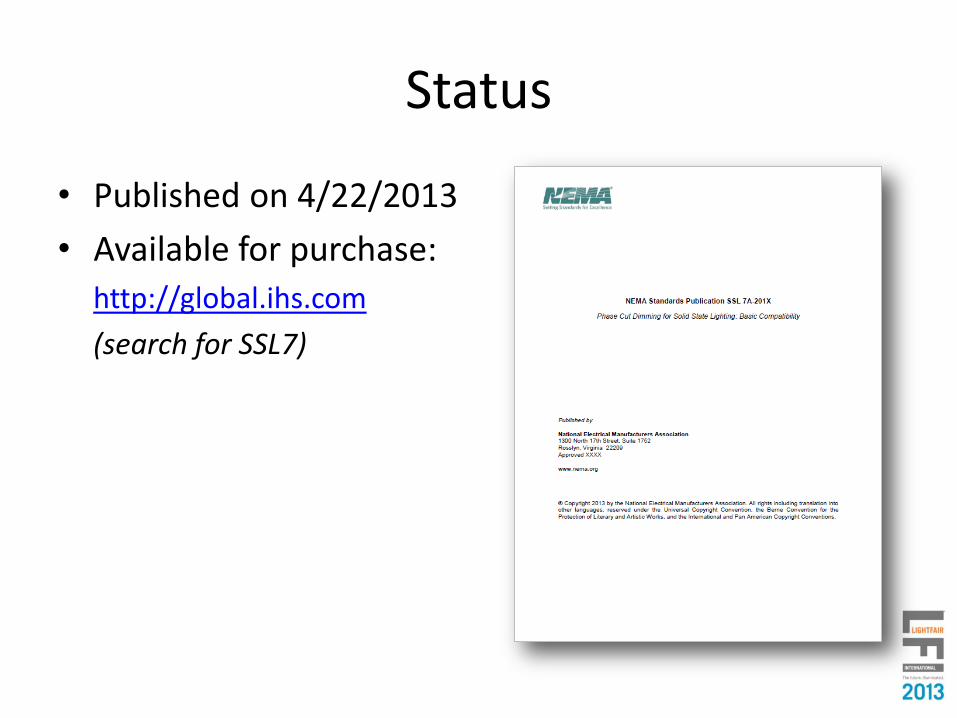
• Published on 4/22/2013
• Available for purchase:
http://global.ihs.com
(search for SSL7)

WHAT COMES NEXT?
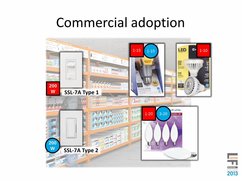
Commercial adoption
1-15 1-15
200
W
SSL-7A Type 1
SSL-7A Type 2
1-20 3-20
1-10
200
W

Specification agents
• Zhaga– Book 1
• EPA ENERGYSTAR– Lamps Specification
– Luminaire Specification
• California Energy Commission– Title 20 (CEC-140-2012-002)
– Voluntary California Quality LED Lamp Specification (CEC-400-2012-016-SF)

Zhaga
“…Whereas this edition of Book does not define a specific technology to realize such dimming functionality, the Product Data Set shall provide at least the following information if the product is to be considered dimmable:
• The required dimming technology, such as forward phase, reverse phase, 0-10V, DALI, etc.
• The expected ratio of the minimum to maximum total luminous flux when dimmed—i.e. a low-end dimming percentage such as 10%, 20%, etc.”
Source: http://www.zhagastandard.org/specifications/book-1.html

EPA ENERGYSTAR
Proposed language included in Lamps Specification Draft 4 Version 1.0 (published 4/19/2013; comment period closes 5/17/2013)
12. DIMMING PERFORMANCE: ALL LAMPS MARKETED AS DIMMABLE

EPA ENERGYSTAR
Proposed language included in Lamps Specification Draft 4 Version 1.0 (published 4/19/2013; comment period closes 5/17/2013)
12. DIMMING PERFORMANCE: ALL LAMPS MARKETED AS DIMMABLE

EPA ENERGYSTAR
Proposed language included in Lamps Specification Draft 4 Version 1.0 (published 4/19/2013; comment period closes 5/17/2013)
12. DIMMING PERFORMANCE: ALL LAMPS MARKETED AS DIMMABLE

California Energy Commission
California Code of Regulations, Title 20. Public Utilities and Energy, November 2012 (CEC-140-2012-002)
Chapter 3. Energy Conservation, Article 4 Appliance Efficiency Regulations
• Does not contain any dimming requirements

Voluntary California Quality Light-Emitting Diode (LED) Lamp Specification, December 2012 (CED-400-2012-016-SF)
Chapter 2: Attributes of the Voluntary California Quality LED Lamp Specification
Chapter 3: Voluntary California Quality LED Lamp Specification
California Energy Commission

NEMA Working Group
• Tracking and correcting errata
• Multiple possibilities for further work
– SSL7-A:Compatibility SSL7-B: Performance?
– Reverse Phase?
• Decision TBD

Other paths to improved dimming?
• Zigbee Lightlink– Wireless mesh communication built on IEEE 802.15.4
PHY and MAC
– Separate AC power and control signal
– Digital, two-way communication

Other paths to improved dimming?
• DLT / IEC 62756-1– Digital Load Line Transmission– Coincident AC power and control signal (powerline
carrier, NOT phase-cut)– Digital, one-way communication
• Connected Lighting Alliance– New (8/2012) manufacturer consortium (like Zhaga)– Promotes wireless lighting solutions by supporting
open standards– Ensure interoperability– Initial focus on residential/consumer applications

Please remember to completethe course evaluations.
Thank you.
We hope you enjoy the trade show and conference!
We hope to see you at LFI 2014!www.lightfair.com


