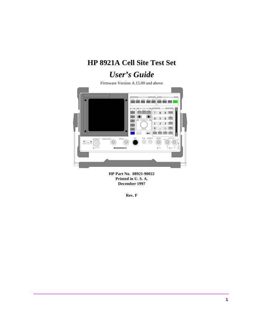
HP 8921A Cell Site Test Set
User’s GuideFirmware Version A.15.00 and above
HP Part No. 08921-90022Printed in U. S. A.
December 1997
Rev. F
DUPLETXRX PREV TESTS
CONFIHELPMSSG HOLD PRINT
SCREEN CONTROL
LOCAL
ADRS
RECAL
SAVE
MEAS PRESE
INSTRUMENT STATE
DATA FUNCTIONS
INCRREF
INCR METER
INCR AVG
LO HI
CURSOR CON-
PUSH TO
CANCESHIFT
k1
k1’
k2
k2’
k3
k3’
k4
ASSIG
k5
RELEA
USER DATA
7 8 9
4 5 6
1 2 3
0 + _
ENTER
GHz
dB
MHz
%
kHz
s
Hz
ms
%
Ωppm
NO
ON/OFF
YES
MEMO
AUDIO INLOHI
! MAX! MAX
AUDIO SQUELCVOL-MIC/
MAX POWER 200 !
ANT INDUPLEX OUTRF IN/OUT
! MAX POWER
POWEOF O
1
Copyright © Hewlett-Packard Company 1995
Notice Information contained in this document is subject to change without notice.
All Rights Reserved. Reproduction, adaptation, or translation without prior written permission is prohibited, except as allowed under the copyright laws.
This material may be reproduced by or for the U.S. Government pursuant to the Copyright License under the clause at DFARS 52.227-7013 (APR 1988).
Hewlett-Packard CompanyLearning Products Department24001 E. MissionLiberty Lake, WA 99019-9599U.S.A.
2
Manufacturer’s Declaration
This statement is provided to comply with the requirements of the German Sound Emission Directive, from 18 January 1991.
This product has a sound pressure emission (at the operator position) < 70 dB(A).
• Sound Pressure Lp < 70 dB(A).• At Operator Position.• Normal Operation.• According to ISO 7779:1988/EN 27779:1991 (Type Test).
Herstellerbescheinigung
Diese Information steht im Zusammenhang mit den Anforderungen der Maschinenlärminformationsverordnung vom 18 Januar 1991.
• Schalldruckpegel Lp < 70 dB(A).• Am Arbeitsplatz.• Normaler Betrieb.• Nach ISO 7779:1988/EN 27779:1991 (Typprüfung).
3
Safety Considerations
GENERAL
This product and related documentation must be reviewed for familiarization with safety markings and instructions before operation.
This product has been designed and tested in accordance with IEC Publication 1010, "Safety Requirements for Electronic Measuring Apparatus," and has been supplied in a safe condition. This instruction documentation contains information and warnings which must be followed by the user to ensure safe operation and to maintain the product in a safe condition.
SAFETY EARTH GROUND
A uninterruptible safety earth ground must be provided from the main power source to the product input wiring terminals, power cord, or supplied power cord set.
CHASSIS GROUND TERMINAL
To prevent a potential shock hazard, always connect the rear-panel chassis ground terminal to earth ground when operating this instrument from a dc power source.
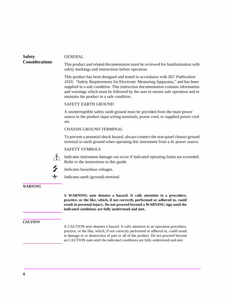
SAFETY SYMBOLS
Indicates instrument damage can occur if indicated operating limits are exceeded. Refer to the instructions in this guide.
Indicates hazardous voltages.
Indicates earth (ground) terminal
WARNING
A WARNING note denotes a hazard. It calls attention to a procedure,practice, or the like, which, if not correctly performed or adhered to, couldresult in personal injury. Do not proceed beyond a WARNING sign until theindicated conditions are fully understood and met.
CAUTIONA CAUTION note denotes a hazard. It calls attention to an operation procedure,practice, or the like, which, if not correctly performed or adhered to, could resultin damage to or destruction of part or all of the product. Do not proceed beyondan CAUTION note until the indicated conditions are fully understood and met.
!
4
Safety Considerations for this Instrument
WARNING This product is a Safety Class I instrument (provided with a protectiveearthing ground incorporated in the power cord). The mains plug shall onlybe inserted in a socket outlet provided with a protective earth contact. Anyinterruption of the protective conductor inside or outside of the product islikely to make the product dangerous. Intentional interruption isprohibited..
Whenever it is likely that the protection has been impaired, the instrumentmust be made inoperative and be secured against any unintended operation.
If this instrument is to be energized via an autotransformer (for voltagereduction), make sure the common terminal is connected to the earthterminal of the power source.
If this product is not used as specified, the protection provided by theequipment could be impaired. This product must be used in a normalcondition (in which all means for protection are intact) only.
No operator serviceable parts in this product. Refer servicing to qualifiedpersonnel. To prevent electrical shock, do not remove covers.
Servicing instructions are for use by qualified personnel only. To avoidelectrical shock, do not perform any servicing unless you are qualified to doso.
The opening of covers or removal of parts is likely to expose dangerousvoltages. Disconnect the product from all voltage sources while it is beingopened.
Adjustments described in the manual are performed with power supplied tothe instrument while protective covers are removed. Energy available atmany points may, if contacted, result in personal injury.
The power cord is connected to internal capacitors that my remain live for 5 seconds after disconnecting the plug from its power supply.
For Continued protection against fire hazard, replace the line fuse(s) onlywith 250 V fuse(s) or the same current rating and type (for example, normalblow or time delay). Do not use repaired fuses or short circuitedfuseholders.
5
CAUTION: Always use the three-prong ac power cord supplied with this product. Failure to ensureadequate earth grounding by not using this cord may cause product damage.
This product is designed for use in Installation Category II and Pollution Degree2 per IEC 1010 and IEC 664 respectively. For indoor use only.
This product has autoranging line voltage input, be sure the supply voltage iswithin the specified range.
Ventilation Requirements: When installing the product in a cabinet, theconvection into and out of the product must not be restricted. The ambienttemperature (outside the cabinet) must be less than the maximum operatingtemperature of the product by 4° C for every 100 watts dissipated in the cabinet.If the total power dissipated in the cabinet is greater than 800 watts, then forcedconvection must be used.
Product Markings CE - the CE mark is a registered trademark of the European Community. A CE mark accompanied by a year indicated the year the design was proven.
CSA - the CSA mark is a registered trademark of the Canadian Standards Associ-ation.
6

ali-s
CERTIFICATION Hewlett-Packard Company certifies that this product met its published specifica-tions at the time of shipment from the factory. Hewlett-Packard further certifies that its calibration measurements are traceable to the United States National In-stitute of Standards and Technology, to the extent allowed by the Institute’s cbration facility, and to the calibration facilities of other International StandardOrganization members
WARRANTY This Hewlett-Packard instrument product is warranted against defects in material and workmanship for a period of one year from date of shipment. During the war-ranty period, Hewlett-Packard Company will at its option, either repair or replace products which prove to be defective.
For warranty service or repair, this product must be returned to a service facility designated by HP. Buyer shall prepay shipping charges to HP and HP shall pay shipping charges, duties, and taxes for products returned to HP from another coun-try.
HP warrants that its software and firmware designated by HP for use with an in-strument will execute its programming instructions when properly installed on that instrument. HP does not warrant that the operation of the instrument, or software, or firmware will be uninterrupted or error free.
LIMITATION OF WARRANTY
The foregoing warranty shall not apply to defects resulting from improper or inad-equate maintenance by Buyer, Buyer-supplied software or interfacing, unautho-rized modification or misuse, operation outside of the environmental specifications for the product, or improper site preparation or maintenance.
NO OTHER WARRANTY IS EXPRESSED OR IMPLIED. HP SPECIFICALLY DISCLAIMS THE IMPLIED WARRANTIES OF MERCHANTABILITY AND FITNESS FOR A PARTICULAR PURPOSE.
EXCLUSIVE REMEDIES
THE REMEDIES PROVIDED HEREIN ARE BUYER’S SOLE AND EXCLU-SIVE REMEDIES. HP SHALL NOT BE LIABLE FOR ANY DIRECT, INDI-RECT, SPECIAL, INCIDENTAL, OR CONSEQUENTIAL DAMAGES, WHETHER BASE ON CONTRACT, TORT, OR ANY OTHER LEGAL THEO-RY.
ASSISTANCE Product maintenance agreements and other customer assistance agreements are available for Hewlett-Packard products. For any assistance, contact your nearest Hewlett-Packard Sales and Service Office.
7
European Contact: Your local Hewlett-Packard Sales and Service Office or Hewlett-Packard GmbHDepartment ZQ/Standards Europe, Herrenberger Strasse 130, D-71034 Böblinger, Germany (FAX+49-7031-14-3143)
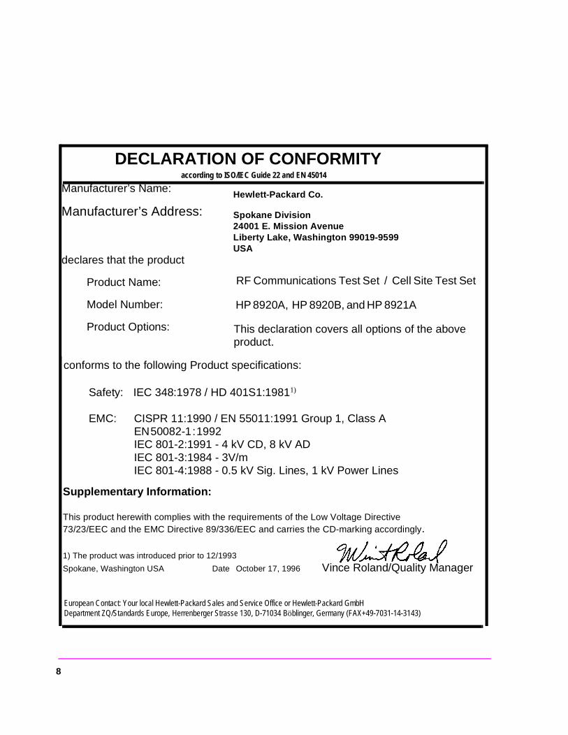
DECLARATION OF CONFORMITY according to ISO/IEC Guide 22 and EN 45014
Manufacturer’s Name:
Manufacturer’s Address:
declares that the product
Product Name:
Model Number:
Product Options:
Hewlett-Packard Co.
Spokane Division24001 E. Mission AvenueLiberty Lake, Washington 99019-9599USA
RF Communications Test Set / Cell Site Test Set
HP 8920A, HP 8920B, and HP 8921A
This declaration covers all options of the above product.
conforms to the following Product specifications:
Safety: IEC 348:1978 / HD 401S1:19811)
EMC: CISPR 11:1990 / EN 55011:1991 Group 1, Class A EN 50082-1 : 1992 IEC 801-2:1991 - 4 kV CD, 8 kV ADIEC 801-3:1984 - 3V/mIEC 801-4:1988 - 0.5 kV Sig. Lines, 1 kV Power Lines
Supplementary Information:
This product herewith complies with the requirements of the Low Voltage Directive 73/23/EEC and the EMC Directive 89/336/EEC and carries the CD-marking accordingly.
1) The product was introduced prior to 12/1993
Spokane, Washington USA Date October 17, 1996 Vince Roland/Quality Manager
8
et
Set
tory
et is
HP 8924C Support Contacts
The documentation supplied with your test set is an excellent source of reference, applications, and service information. Please use these manuals if you are experi-encing technical problems:
• Applications information is included in the HP 8924C CDMA Mobile Station Test SApplication Guide (HP P/N 08924-90021)
• Calibration and repair information are in the HP 8924C CDMA Mobile Station Test Assembly Level Repair Manual - this manual (HP P/N 08924-90001).
If you have used the manuals and still have application questions, contact your lo-cal HP Sales Representative.
Repair assistance is available for the HP 8924C CDMA Mobile Test Set from the facby phone and e-mail. Internal Hewlett-Packard users can contact the factory throughHPDesk or cc:Mail© (Lotus Corporation). Parts information is also available from Hewlett-Packard.
When calling or writing for repair assistance, please have the following information ready:
• Instrument model number (HP 8924C)• Instrument Serial Number (tag located on the rear panel).• Installed options - if any (tag located on the rear panel).• Instrument firmware revision (displayed at the top of the screen when the Test S
powered up, and is also displayed on the CONFIGURE screen).Support Telephone Numbers:
1 800 827 3848 (Spokane Division Service Assistance, U.S. only) 1 509 921 3848 (Spokane Division Service Assistance, International) 1 800 227 8164 (HP Direct Parts Ordering, U.S. only) 1 916 783 0804 (HP Service Parts Identification, U.S. & Intl.)
Electronic mail (Internet): [email protected]
HP Desk: Spokane Service / HP1000/21
cc:Mail: SERVICE, SPOKANE /HP-Spokane,desk1
9
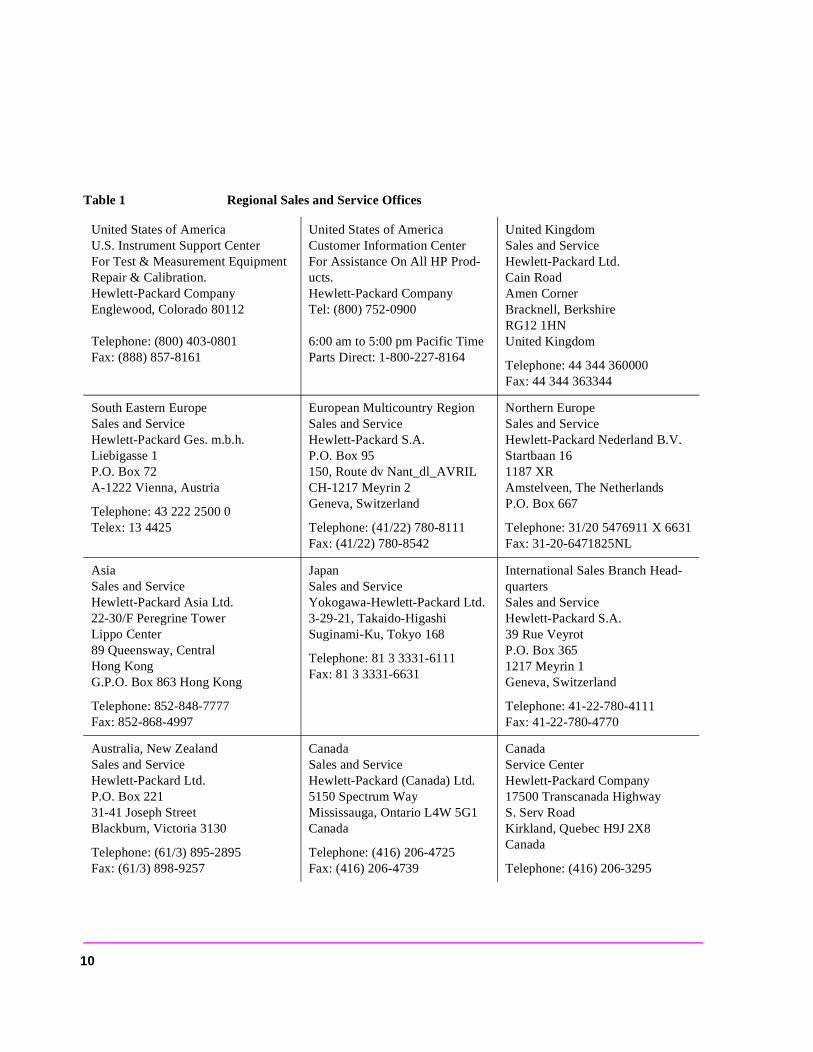
Table 1 Regional Sales and Service Offices
United States of AmericaU.S. Instrument Support CenterFor Test & Measurement Equipment Repair & Calibration.Hewlett-Packard CompanyEnglewood, Colorado 80112
Telephone: (800) 403-0801Fax: (888) 857-8161
United States of AmericaCustomer Information CenterFor Assistance On All HP Prod-ucts.Hewlett-Packard CompanyTel: (800) 752-0900
6:00 am to 5:00 pm Pacific TimeParts Direct: 1-800-227-8164
United KingdomSales and ServiceHewlett-Packard Ltd.Cain RoadAmen CornerBracknell, BerkshireRG12 1HNUnited Kingdom
Telephone: 44 344 360000Fax: 44 344 363344
South Eastern EuropeSales and ServiceHewlett-Packard Ges. m.b.h.Liebigasse 1P.O. Box 72A-1222 Vienna, Austria
Telephone: 43 222 2500 0Telex: 13 4425
European Multicountry RegionSales and ServiceHewlett-Packard S.A.P.O. Box 95150, Route dv Nant_dl_AVRILCH-1217 Meyrin 2Geneva, Switzerland
Telephone: (41/22) 780-8111Fax: (41/22) 780-8542
Northern EuropeSales and ServiceHewlett-Packard Nederland B.V.Startbaan 161187 XRAmstelveen, The NetherlandsP.O. Box 667
Telephone: 31/20 5476911 X 6631Fax: 31-20-6471825NL
AsiaSales and ServiceHewlett-Packard Asia Ltd.22-30/F Peregrine TowerLippo Center89 Queensway, CentralHong KongG.P.O. Box 863 Hong Kong
Telephone: 852-848-7777Fax: 852-868-4997
JapanSales and ServiceYokogawa-Hewlett-Packard Ltd.3-29-21, Takaido-HigashiSuginami-Ku, Tokyo 168
Telephone: 81 3 3331-6111Fax: 81 3 3331-6631
International Sales Branch Head-quartersSales and ServiceHewlett-Packard S.A.39 Rue VeyrotP.O. Box 3651217 Meyrin 1Geneva, Switzerland
Telephone: 41-22-780-4111Fax: 41-22-780-4770
Australia, New ZealandSales and ServiceHewlett-Packard Ltd.P.O. Box 22131-41 Joseph StreetBlackburn, Victoria 3130
Telephone: (61/3) 895-2895Fax: (61/3) 898-9257
CanadaSales and ServiceHewlett-Packard (Canada) Ltd.5150 Spectrum WayMississauga, Ontario L4W 5G1Canada
Telephone: (416) 206-4725Fax: (416) 206-4739
CanadaService CenterHewlett-Packard Company17500 Transcanada HighwayS. Serv RoadKirkland, Quebec H9J 2X8Canada
Telephone: (416) 206-3295
10
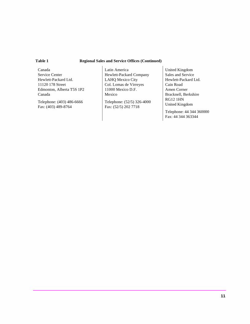
CanadaService CenterHewlett-Packard Ltd.11120 178 StreetEdmonton, Alberta T5S 1P2Canada
Telephone: (403) 486-6666Fax: (403) 489-8764
Latin AmericaHewlett-Packard CompanyLAHQ Mexico CityCol. Lomas de Virreyes11000 Mexico D.F.Mexico
Telephone: (52/5) 326-4000Fax: (52/5) 202 7718
United KingdomSales and ServiceHewlett-Packard Ltd.Cain RoadAmen CornerBracknell, BerkshireRG12 1HNUnited Kingdom
Telephone: 44 344 360000Fax: 44 344 363344
Table 1 Regional Sales and Service Offices (Continued)
11
func-top of mes
avail-
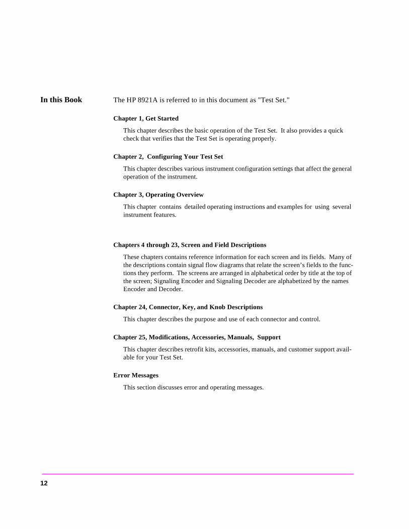
In this Book The HP 8921A is referred to in this document as "Test Set."
Chapter 1, Get Started
This chapter describes the basic operation of the Test Set. It also provides a quick check that verifies that the Test Set is operating properly.
Chapter 2, Configuring Your Test Set
This chapter describes various instrument configuration settings that affect the general operation of the instrument.
Chapter 3, Operating Overview
This chapter contains detailed operating instructions and examples for using several instrument features.
Chapters 4 through 23, Screen and Field Descriptions
These chapters contains reference information for each screen and its fields. Many of the descriptions contain signal flow diagrams that relate the screen’s fields to the tions they perform. The screens are arranged in alphabetical order by title at the the screen; Signaling Encoder and Signaling Decoder are alphabetized by the naEncoder and Decoder.
Chapter 24, Connector, Key, and Knob Descriptions
This chapter describes the purpose and use of each connector and control.
Chapter 25, Modifications, Accessories, Manuals, Support
This chapter describes retrofit kits, accessories, manuals, and customer supportable for your Test Set.
Error Messages
This section discusses error and operating messages.
12
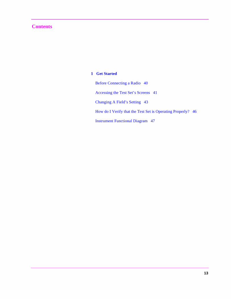
Contents
1 Get Started
Before Connecting a Radio 40
Accessing the Test Set’s Screens 41
Changing A Field’s Setting 43
How do I Verify that the Test Set is Operating Properly? 46
Instrument Functional Diagram 47
13
Contents
2 Configuring Your Test Set
General Operating Information 50
14
Contents
3 Operating Overview
Interaction Between Screens 54
Displaying Measurements 57
Entering and Changing Numbers 63
Printing A Screen 66
Using Measurement Limit Indicators 67
Averaging Measurements 69
Setting A Measurement Reference 70
Saving and Recalling Instrument Setups 71
Using USER Keys 75
Setting an RF Generator/Analyzer Offset 79
Using Remote Control 80
15

Contents
4 Adjacent Channel Power Screen
How the Test Set Measures Adjacent Channel Power (ACP) 86
Field Descriptions 87
16

Contents
5 AF Analyzer Screen
Block Diagram 96
17
Contents
6 Call Processing Subsystem
Description of the Call Processing Subsystem 110
Using the Call Processing Subsystem 114
The CALL CONTROL Screen 118
Using the CALL CONTROL Screen to Test Call Processing Functions 129
CALL DATA Screen 139
CALL DATA Screen Message Field Descriptions 144
Using the CALL DATA Screen 153
CALL BIT Screen 161
CALL BIT Screen Message Field Descriptions 167
Using the CALL BIT Screen 187
ANALOG MEAS Screen 192
Using the ANALOG MEAS Screen 195
CALL CONFIGURE Screen 198
18

Contents
7 Configure Screen
Field Descriptions 202
19
Contents
8 Signaling Decoder Screen
Field Descriptions for Decoder Modes 216
AMPS-TACS, NAMPS-NTACS Decoder 217
Using the AMPS/TACS, NAMPS/NTACS Decoder 222
Continuous Digital Controlled Squelch System Decoder 226
Using the CDCSS Decoder 230
Digital Paging Decoder 231
Dual-Tone Multi-Frequency (DTMF) Decoder 235
Using the DTMF Decoder 240
EDACS Decoder 241
Using the EDACS Decoder 244
Function Generator Decoder 247
Using the Function Generator Decoder 250
LTR Decoder 251
Using the LTR Decoder 255
MPT 1327 Decoder 257
NMT Decoder 262
Using the NMT Decoder/Encoder 267
Creating NMT Tests 272
Tone Sequence Decoder 281
20

Contents
9 Duplex Test Screen
Block Diagram 286
Field Descriptions 287
21
Contents
10 Signaling Encoder (AF Generator 2)
Field Descriptions for Encoder Modes 300
AMPS-TACS NAMPS-NTACS Encoder 301
Using the AMPS-TACS, NAMPS-NTACS Encoder 313
CDCSS Encoder 314
Using the CDCSS Encoder 318
Digital Paging Encoder 319
DTMF Sequence Encoder 324
EDACS Encoder 328
Using the EDACS Encoder 334
Function Generator Encoder 339
LTR Encoder 342
Using the LTR Encoder 346
MPT 1327 Encoder 350
Using the MPT 1327 Encoder 363
Nordic Mobile Telephone (NMT) Encoder 366
Tone Sequence Encoder 378
22

Contents
11 Help Screen
Field Descriptions 382
23
Contents
12 I/O Configure Screen
Field Descriptions 384
24

Contents
13 Message Screen
Field Descriptions 390
25

Contents
14 Oscilloscope Screen
Field Descriptions 392
Using the Oscilloscope 398
26
Contents
15 Print Configure Screen
Field Descriptions 400
27
Contents
16 Radio Interface Screen
Radio Interface Functional Description 404
Field Descriptions 406
Using the Radio Interface (Manual Operation) 409
Using The Radio Interface (Remote Operation) 415
28

Contents
17 RF Analyzer Screen
Block Diagram 418
Field Descriptions 419
29
Contents
18 RF Generator Screen
Block Diagram 430
Field Descriptions 431
30

Contents
19 RX Test Screen
Block Diagram 440
Field Descriptions 441
31

Contents
20 Service Screen
Field Descriptions 448
32
Contents
21 Spectrum Analyzer Screen
Field Descriptions 452
Using the Spectrum Analyzer 464
33
Contents
22 Tests Screen
Description of the Tests Subsystem 466
TESTS (Main Menu) 468
TESTS (Channel Information) 471
TESTS (Test Parameters) 473
TESTS (Order of Tests) 474
TESTS (Pass/Fail Limits) 476
TESTS (Save/Delete Procedure) 478
TESTS (Execution Conditions) 481
TESTS (External Devices) 484
TESTS (Printer Setup) 487
TESTS (IBASIC Controller) 490
ROM Programs 492
34

Contents
23 TX Test Screen
Block Diagram 496
Field Descriptions 497
35
Contents
24 Connector, Key, and Knob Descriptions
Connector Descriptions 508
Key Descriptions 526
Knob Descriptions 530
36
Contents
25 Modifications, Accessories, Manuals, Support
Modifications 532
Accessories 535
HP Support for Your Instrument 546
37

Contents
38

1
Get Started
39
Chapter 1, Get StartedBefore Connecting a Radio
el.
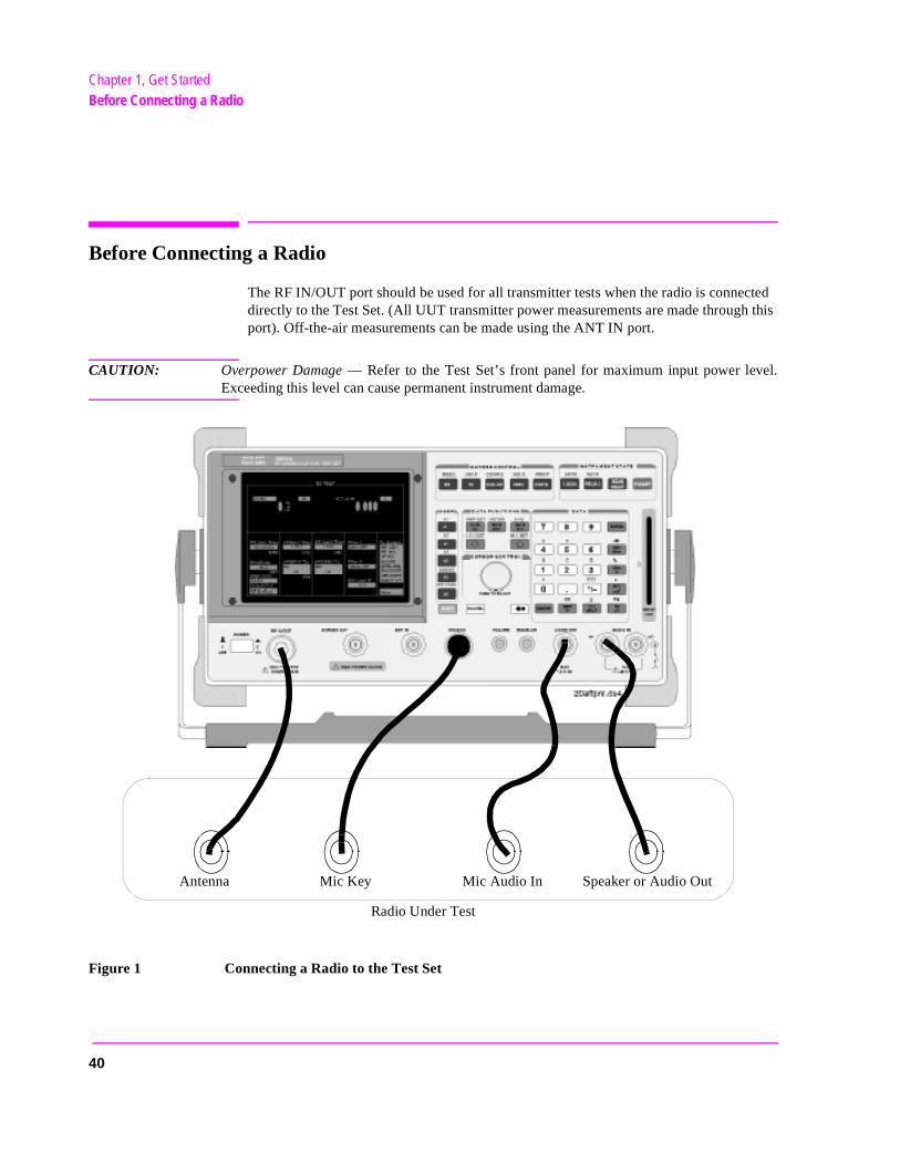
Before Connecting a Radio
The RF IN/OUT port should be used for all transmitter tests when the radio is connected directly to the Test Set. (All UUT transmitter power measurements are made through this port). Off-the-air measurements can be made using the ANT IN port.
CAUTION: Overpower Damage — Refer to the Test Set’s front panel for maximum input power levExceeding this level can cause permanent instrument damage.
Figure 1 Connecting a Radio to the Test Set
Speaker or Audio OutMic Audio InMic KeyAntenna
Radio Under Test
40
Chapter 1, Get StartedAccessing the Test Set’s Screens
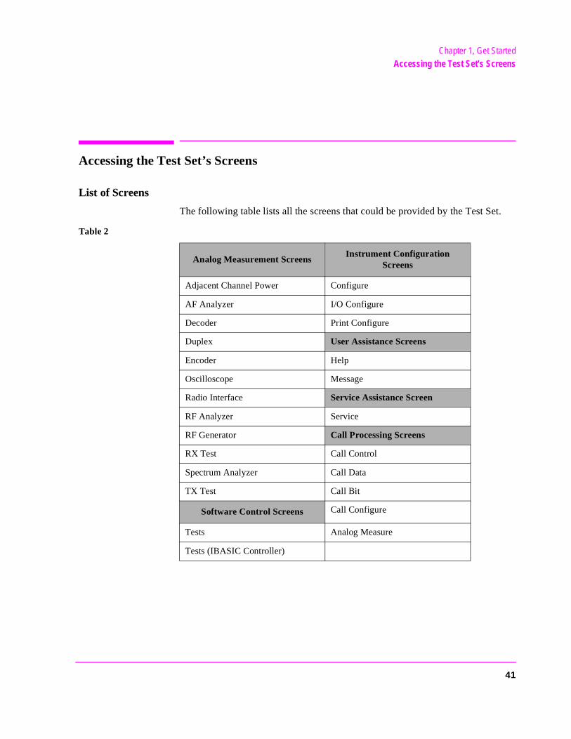
Accessing the Test Set’s Screens
List of Screens
The following table lists all the screens that could be provided by the Test Set.
Table 2
Analog Measurement ScreensInstrument Configuration
Screens
Adjacent Channel Power Configure
AF Analyzer I/O Configure
Decoder Print Configure
Duplex User Assistance Screens
Encoder Help
Oscilloscope Message
Radio Interface Service Assistance Screen
RF Analyzer Service
RF Generator Call Processing Screens
RX Test Call Control
Spectrum Analyzer Call Data
TX Test Call Bit
Software Control Screens Call Configure
Tests Analog Measure
Tests (IBASIC Controller)
41
Chapter 1, Get StartedAccessing the Test Set’s Screens
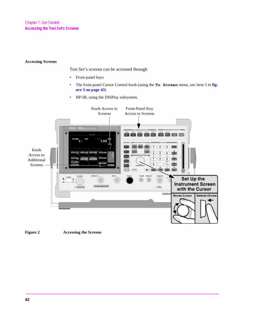
Accessing Screens
Test Set’s screens can be accessed through
• Front-panel keys
• The front-panel Cursor Control knob (using the To Screen menu, see item 5 in fig-ure 3 on page 43)
• HP-IB, using the DISPlay subsystem.
Figure 2 Accessing the Screens
Front-Panel Key Access to Screens
Knob Access to Additional
Screens
Knob Access to Screens
42
Chapter 1, Get StartedChanging A Field’s Setting
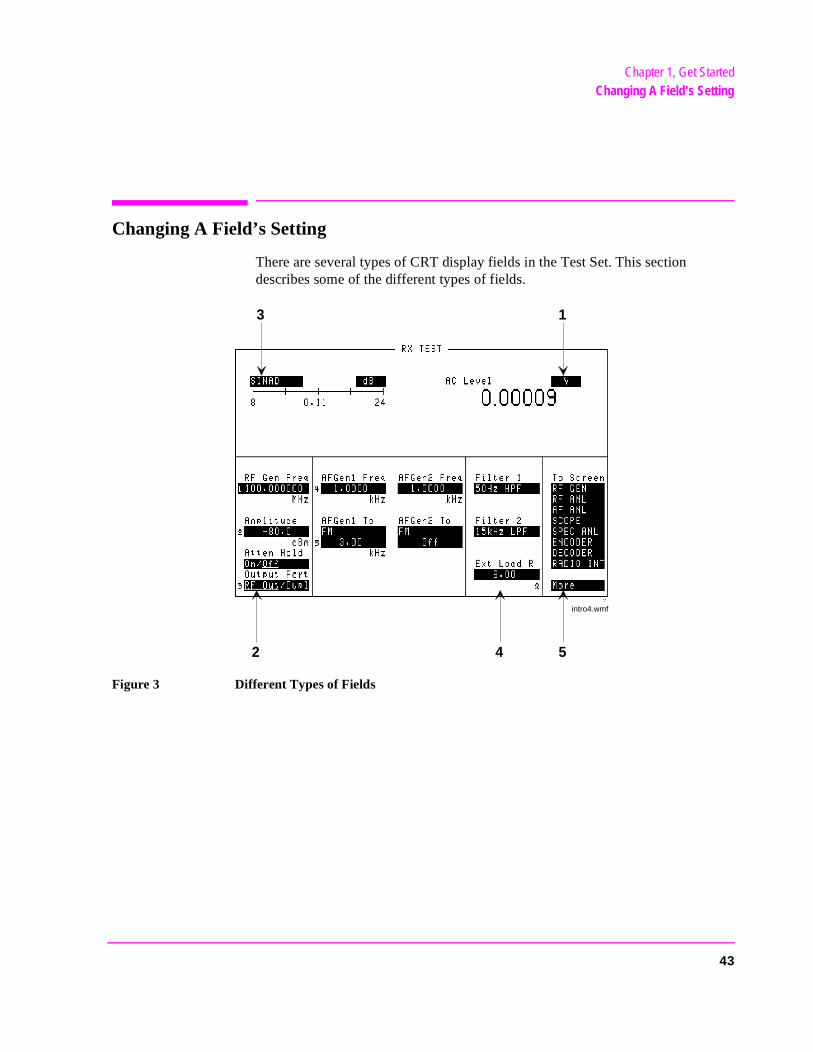
Changing A Field’s Setting
There are several types of CRT display fields in the Test Set. This section describes some of the different types of fields.
Figure 3 Different Types of Fields
rxscrn.wmf
1
542
3
intro4.wmf
43
Chapter 1, Get StartedChanging A Field’s Setting
Unit-of-Measure Field
Unit-of-measure can be changed to display measurements in different values or magnitudes. See item 1 in figure 3 to see an example of a units-of-measure field.
To change a unit-of-measure1. Position the cursor at the unit field on the display.2. Press a key labeled with a different unit-of-measure (such as W).
If the new units are valid, the measurement value is displayed in the unit.
Underlined Immediate-Action Field
Underlined immediate action fields provide a choice of two settings. See item 2 in figure 3 to see an example of an underlined immediate-action field.
To change an underlined entry1. Position the cursor at the field.2. Push the CURSOR CONTROL knob or the ENTER key to move the underline under
the desired choice.
The underlined setting is immediately activated when selected.
44
Chapter 1, Get StartedChanging A Field’s Setting
One-of-Many Field
One-of-many fields display a list of choices when selected. See item 3 in figure 3 to see an example of a one-of many field.
To make a one-of-many choice1. Position the cursor at the field.2. Push the Cursor Control knob or the ENTER key to display the choices.3. Move the cursor through the choices by turning the knob.4. Push the Cursor Control knob or the ENTER key to make the choice.
The choice is immediately activated when selected.
The To Screen menu (see item 5 in figure 3 ) is a variation of the one-of-many field.
Numeric-Entry Field
Numeric-entry fields contain values for settings like External Load Resistance and RF Generator Frequency.See item 4 in figure 3 to see an example of a numeric-entry field.
To change a value1. Position the cursor at the field.2. Key in the desired number using the DATA keys.3. Press ENTER to select the choice.
OR
1. Position the cursor at the field.2. Push the Cursor Control knob to highlight the desired choice.3. Turn the knob to increment or decrement the value.4. Push the Cursor Control knob or the ENTER key to select the choice.
45
Chapter 1, Get StartedHow do I Verify that the Test Set is Operating Properly?
How do I Verify that the Test Set is Operating Properly?
If your Test Set powers-up and displays the RX TEST screen, but you suspect an instrument problem, use the Instrument Quick Check to verify operation of the basic instrument functions.
If no failure is indicated by this test, but you still suspect a problem, refer to the “Performance Tests” information in the Assembly Level Repair Manual.
Instrument Quick Check
1. Set up the quick check:
a. Connect a cable between the DUPLEX OUT and ANT IN ports.b. Turn instrument power on (if it is not already on). c. Press PRESET.d. Press DUPLEX to access the DUPLEX TEST screen.e. Set the Tune Mode field to Manual.f. Set the Tune Freq field to 825 MHz.g. Set the Input Port field to Ant.h. Set the RF Gen Freq field to 825 MHz.i. Set the Amplitude field to -10 dBm.j. Set the Output Port field to Dupl.k. Verify that AFGen1 Freq is set to 1.0000 kHz, and that AFGen1 To is set to
FM and 3.00 kHz.l. Set the AF Anl In field to FM Demod.m. Set the Filter 1 field to 300Hz HPF.n. Set the Filter 2 field to 3kHz LPF.o. Verify that De-Emphasis is Off.p. Set the Detector field to Pk+-/2.q. Turn the VOLUME knob clockwise until you hear a tone (1 kHz default for
AFGen1 Freq).
2. Check the following readings:
SINAD should be >35 dB. FM Deviation should be about 3.0 kHz.
3 Access the OSCILLOSCOPE screen using the To Screen menu. With the default Vert/div setting of 2 kHz and a default Time/div setting of 200 µs, you should see two complete sinewaves across the screen.
4 Access the SPECTRUM ANALYZER using the To Screen menu. You should see an 850 MHz FM carrier.
46
Chapter 1, Get StartedInstrument Functional Diagram
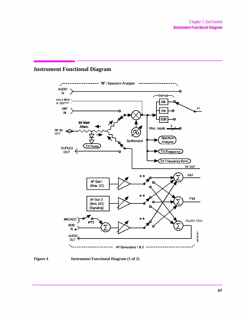
Instrument Functional Diagram
Figure 4 Instrument Functional Diagram (1 of 2)
47
Chapter 1, Get StartedInstrument Functional Diagram
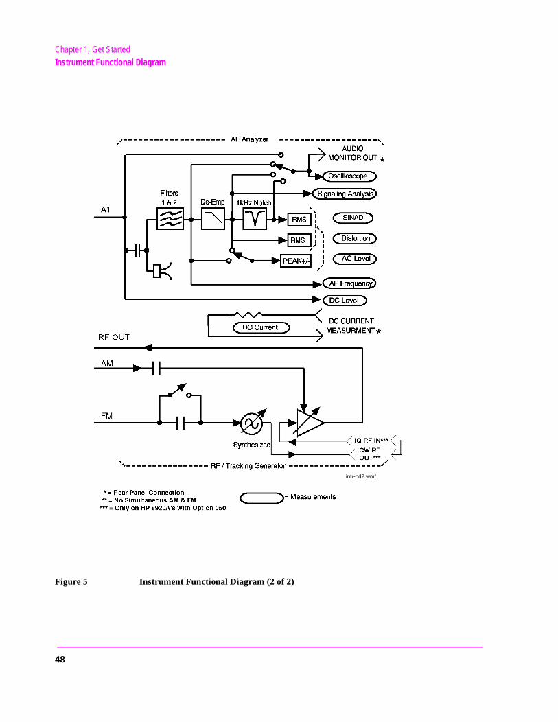
Figure 5 Instrument Functional Diagram (2 of 2)
intr-bd2.wmf
48
2
Configuring Your Test Set
The CONFIGURE and I/O CONFIGURE screens contain a number of settings used to alter instrument operation and hardware communication settings. The HP-IB address, screen intensity, serial communication parameters, and several other settings, are changed in these screens.
Most CONFIGURE and I/O CONFIGURE screen entries are saved when the instrument is turned off.
49
Chapter 2, Configuring Your Test SetGeneral Operating Information
des.
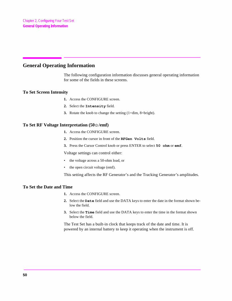
General Operating Information
The following configuration information discusses general operating information for some of the fields in these screens.
To Set Screen Intensity
1. Access the CONFIGURE screen.
2. Select the Intensity field.
3. Rotate the knob to change the setting (1=dim, 8=bright).
To Set RF Voltage Interpretation (50 /emf)
1. Access the CONFIGURE screen.
2. Position the cursor in front of the RFGen Volts field.
3. Press the Cursor Control knob or press ENTER to select 50 ohm or emf.
Voltage settings can control either:
• the voltage across a 50-ohm load, or
• the open circuit voltage (emf).
This setting affects the RF Generator’s and the Tracking Generator’s amplitu
To Set the Date and Time
1. Access the CONFIGURE screen.
2. Select the Date field and use the DATA keys to enter the date in the format shown be-low the field.
3. Select the Time field and use the DATA keys to enter the time in the format shown below the field.
The Test Set has a built-in clock that keeps track of the date and time. It is powered by an internal battery to keep it operating when the instrument is off.
Ω
50
Chapter 2, Configuring Your Test SetGeneral Operating Information
To Change the Beeper Volume
1. Access the CONFIGURE screen.
2. Select the Beeper field to display the volume choices.
3. Select the desired choice.
The beeper alerts you to important operating and measurement conditions. It beeps any time a message is displayed at the top of the screen. These messages warn you of conditions such as exceeding the RF input level or trying to set a field to an unacceptable value. Therefore, it is recommended that you do not disable the beeper.
To Verify or Change the Low-Battery Setting
1. Access the CONFIGURE screen.
2. The current time setting is shown under the Low Battery field.
3. Select that field to display a list of setting choices.
• Select the desired time, or
• Select Disable to eliminate the low-battery warning.
The low-battery warning system is used to alert you when you have not used any front-panel controls within a specified amount of time. This setting is only used with DC power. It does not actually monitor the DC supply voltage. Since batteries are most often used for a DC supply, this function helps you conserve power by reminding you that the Test Set is still turned on.
When the specified time has elapsed between front-panel entries, the Beeper sounds and a message appears at the top of the screen alerting you to the condition.
This setting is saved when the instrument is turned off.
51

Chapter 2, Configuring Your Test SetGeneral Operating Information
52
3
Operating Overview
The information in this section discusses some frequently used operating features of the Test Set.
From reading chapter 1, "Get Started" you should understand:
• What “fields” and “screens” are. • How to use the Cursor Control knob to select different fields and screens.
53
Chapter 3, Operating OverviewInteraction Between Screens
Interaction Between Screens
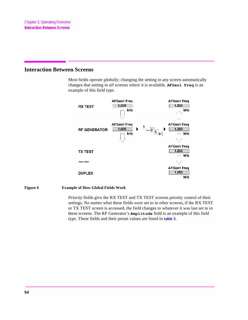
Most fields operate globally; changing the setting in any screen automatically changes that setting in all screens where it is available. AFGen1 Freq is an example of this field type.
Figure 6 Example of How Global Fields Work
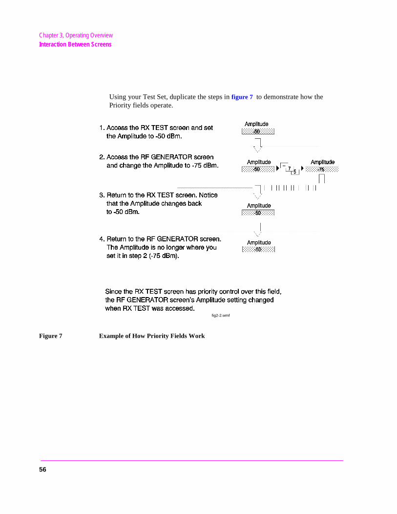
Priority fields give the RX TEST and TX TEST screens priority control of their settings. No matter what these fields were set to in other screens, if the RX TEST or TX TEST screen is accessed, the field changes to whatever it was last set to in these screens. The RF Generator’s Amplitude field is an example of this field type. These fields and their preset values are listed in table 3.
54
Chapter 3, Operating OverviewInteraction Between Screens
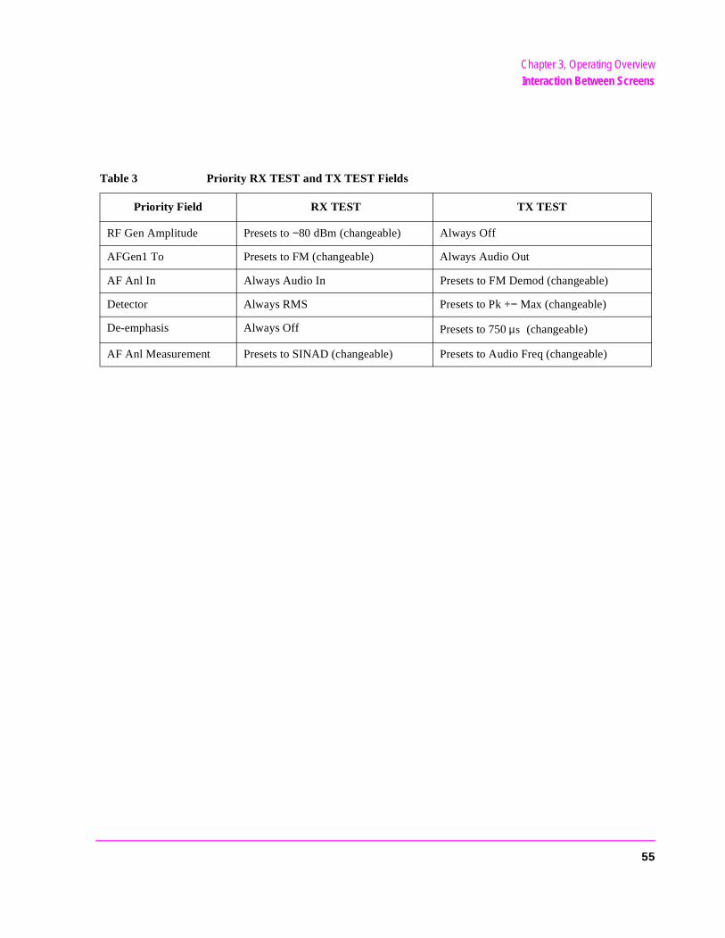
Table 3 Priority RX TEST and TX TEST Fields
Priority Field RX TEST TX TEST
RF Gen Amplitude Presets to −80 dBm (changeable) Always Off
AFGen1 To Presets to FM (changeable) Always Audio Out
AF Anl In Always Audio In Presets to FM Demod (changeable)
Detector Always RMS Presets to Pk +− Max (changeable)
De-emphasis Always Off Presets to 750 (changeable)
AF Anl Measurement Presets to SINAD (changeable) Presets to Audio Freq (changeable)
µs
55
Chapter 3, Operating OverviewInteraction Between Screens
Using your Test Set, duplicate the steps in figure 7 to demonstrate how the Priority fields operate.
Figure 7 Example of How Priority Fields Work
fig2-2.wmf
56
Chapter 3, Operating OverviewDisplaying Measurements
Displaying Measurements
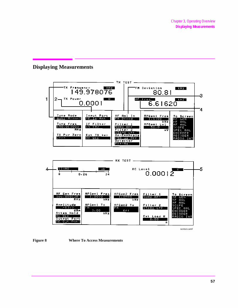
Figure 8 Where To Access Measurements
scntxrx.wmf
57
Chapter 3, Operating OverviewDisplaying Measurements
Displaying RF Measurements
Transmitter Frequency
TX Frequency is displayed when Tune Mode is set to Auto. (Refer to item (1) in figure 8 on page 57.)
Transmitter Frequency Error
TX Freq Error is displayed when Tune Mode is set to Manual. (Refer to item (1) in figure 8 on page 57.)
Transmitter Power
TX Power is only measured and displayed here when the Input Port is set to RF In (Refer to item (2) in figure 8 on page 57). If Ant (antenna) is selected, the measurement is replaced by four dashes (- - - -).
You can measure low power levels on the ANT IN port using the Spectrum Analyzer.
Refer to the TX Power field description, on page 505 and the TX Pwr Zero field description, on page 506 for more information on measuring transmitter power.
CAUTION: Connecting a signal of >200 mW to the ANT IN (antenna) port can cause instrument damage(although internal protection circuits can typically withstand a short-duration signal of 1 or 2Watts). If the overpower circuit is triggered, remove the signal from the ANT IN port and turnthe Test Set off and on to reset it.
58
Chapter 3, Operating OverviewDisplaying Measurements
ent
Displaying AF Measurements
FM Deviation, AM Depth, AC Level
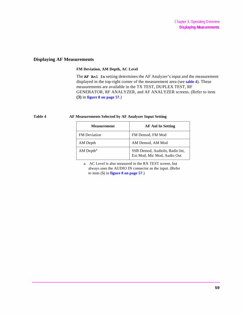
The AF Anl In setting determines the AF Analyzer’s input and the measuremdisplayed in the top-right corner of the measurement area (see table 4). These measurements are available in the TX TEST, DUPLEX TEST, RF GENERATOR, RF ANALYZER, and AF ANALYZER screens. (Refer to item (3) in figure 8 on page 57.)
a. AC Level is also measured in the RX TEST screen, but always uses the AUDIO IN connector as the input. (Refer to item (5) in figure 8 on page 57.)
Table 4 AF Measurements Selected by AF Analyzer Input Setting
Measurement AF Anl In Setting
FM Deviation FM Demod, FM Mod
AM Depth AM Demod, AM Mod
AM Deptha SSB Demod, AudioIn, Radio Int, Ext Mod, Mic Mod, Audio Out
59
Chapter 3, Operating OverviewDisplaying Measurements
SINAD, Distortion, SNR, AF Frequency, DC Level, DC Current
Selecting the currently-displayed measurement causes the To Screen menu to be replaced by a list of measurement choices. Select the new choice to replace the old measurement. These measurements are available in the RX TEST, TX TEST, DUPLEX TEST, RF GENERATOR, RF ANALYZER, and AF ANALYZER screens. (Refer to item (4) in figure 8 on page 57)
The Distortion measurement is only for a 1 kHz tone.
The SINAD measurement is normally shown using an analog-type meter and small digits, but can be changed to display in large digits only. (See "To Use the Analog METER Format" on page 62.)
DC Current can only be measured using the rear-panel DC CURRENT MEASUREMENT connections.
Selecting SNR (Signal/Noise Ratio) turns off the other audio measurement. For more information on making this measurement, see the RF Gen Freq field description, on page 445.
AF Power
AF Power is measured in the RX TEST screen by specifying the external load resistance, Ext Load R, and changing the unit of measure for the AC Level measurement to W (Watts), mW, or dBm. (The milliwatt (mW) unit is selected by pressing SHIFT, ENTER) Refer to item (5) figure 8 on page 57.
60

Chapter 3, Operating OverviewDisplaying Measurements
To Change the Measurement’s Unit-of-Measure
1. Position the cursor in front of the present unit-of-measurement.
2. Press the key labeled with the desired unit.
All measurements allow you to change the associated unit-of- measure. For instance; the TX Power measurement is usually displayed in Watts, but can be changed to display in mW, dBm, V, mV, or dBµV.
Select mW by pressing SHIFT, ENTER.
For example; to display transmitter power in units of dBm instead of Watts:
1. Move the cursor in front of the unit-of-measure for the TX Power measurement (W).
2. Press the dBm key. The measurement value is changed immediately to display in dBm.
61
Chapter 3, Operating OverviewDisplaying Measurements
the ed in
use
gits,
To Use the Analog METER Format
To display measurement results using the analog meter format, use the following procedure.
1. Position the cursor in front of the unit-of-measure for the measurement you want to dis-play.
2. Press and release the SHIFT key, then the INCR SET key to display the Meters menu in the lower-right corner of the screen.
3. Select On/Off to display the meter.
4. Repeat steps 1 and 2 to enter each meter end point and the meter intervals.
5. Repeat steps 1, 2, and 3 to cancel the METER function.
The METER function displays an equivalent analog display. (This is the SINAD measurement’s default state when the instrument is turned on or preset). As measurement is displayed graphically on the meter, the value is also displaysmall digits below the meter.
You can specify the high and low end points and display interval, or you can the default meter settings.
This function is only available for measurements displayed using the large disuch as the measurements displayed in the RX TEST and TX TEST screens.
To Make Beat Frequency Measurements
1. Select the DUPLEX TEST screen to set up for beat frequency oscillator measurements.
2. Set the AF Anl In field to SSB Demod.
3. Manually adjust the Tune Freq field to the desired carrier frequency.
62
Chapter 3, Operating OverviewEntering and Changing Numbers
EEX.
ing
to
Entering and Changing Numbers
Values for numeric entry fields can be entered and changed using various methods, depending on your testing needs. The unit-of-measure for some of these fields can also be changed (such as changing the RF Generator’s Amplitude units from dBm to µV).
To Enter Numbers
1. Position the cursor in front of the numeric entry field to be changed.
2. Use one of the following methods:
a. enter the number and unit-of-measure directly using the keypad,
or
b. press the Cursor Control knob or ENTER to highlight the field, and use the knob,
or
c. use the down-arrow or the up-arrow keys to increment or decrement the present value.
Decimal Values
Decimal values are used for most numeric entry fields, such as the RF Gen Freq setting. The acceptable entries for decimal values are 0 through 9, ., +/-, and
The +/- key is used for entering negative numbers. For example; when enterthe RF Generator Amplitude you can enter this sequence to set the value to −47 dBm: +/- 4 7 dBm.
The EEX key can be used when entering exponential notation. For example;enter 1.25 × 10³ kHz you could use the sequence: 1 . 2 5 EEX 3 kHz.
63

Chapter 3, Operating OverviewEntering and Changing Numbers
Hexadecimal Values
Hexadecimal (Hex) values are used for entering some signaling parameters in the ENCODER, such as AMPS Filler data field, and for specifying remote communications parameters, such as the RADIO INTERFACE Output Data field. The acceptable entries for decimal values are 0 through 9 and A through F. No unit-of-measure is associated with these values.
Hexadecimal values are either entered from the keypad (A through F are shifted functions), or by using the Choices menu displayed when certain fields are selected (such as the AMPS Filler field).
To Enter and Change the Unit-of-Measure
Entering the Unit-of-Measure for Settings
When a number is entered, the unit-of-measure is either specified or implied.
When the unit is implied, the current unit is used. For example; if the present RF frequency is 250 MHz, and you want to change it to 225 MHz, you would enter this sequence: 2 2 5 ENTER.
When the unit is specified, the units change to whatever you specify. For example; if the present RF Gen Freq setting is 250 MHz, and you want to change it to 455 kHz, you would enter this sequence: 4 5 5 kHz.
Changing the Unit-of-Measure for Settings
To change the present unit-of-measure, position the cursor in front of the field and press the key labeled with the desired unit. For example, position the cursor in front of the RF Gen Freq field and push GHz or kHz to display the setting in either of these units.
64
Chapter 3, Operating OverviewEntering and Changing Numbers
b
To Change the Increment or Decrement Setting
Using the Pre-Defined Increment/Decrement Keys
The INCR ×10] and INCR ÷10] keys change the increment/decrement value by a factor of 10.
For example; if the Tune Freq presently changes by 10 MHz for every click of the knob or push of the down-arrow or up-arrow keys, pushing INCR ×10] once changes the increment value to 100 MHz.
Specifying An Increment Value
The INCR SET key is used to assign a specific increment value. The increment value may use different units than the field you are incrementing/decrementing. For instance; if the RF Generator Amplitude setting is displayed in dBµV, you could increment in units of dB or mV.
To change the increment value;
1. Move the cursor to the numeric entry field to be changed.
2. Press INCR SET, and enter the desired value and unit-of-measure using the DATA keys.
3. Use the down-arrow and up-arrow keys or CURSOR CONTROL knob to change the field’s value by the increment value you set.
Example of Setting an Increment Value
This example changes the Tune Freq in increments of 15 MHz.
1. Access the TX TEST screen and position the cursor in front of the Tune Freq field.
2. Press 1 0 0 MHz to set the frequency at 100 MHz.
3. Press INCR SET 1 5 MHz.
4. Turn the Cursor Control knob. The field’s value changes by 15 MHz for each knoclick.
65
Chapter 3, Operating OverviewPrinting A Screen
Printing A Screen
To Print A Screen’s Contents
1. Connect a printer to the appropriate rear-panel connector.
2. Access the PRINT CONFIGURE screen from the More menu and set the Printer Port field to the appropriate type of printer connection.
If HP-IB is selected, enter the HP-IB Printer Address of the printer.
3. Select the type of printer you are using in the Model field. If your printer is not listed, configure your printer to emulate one that is listed.
4. Enter a Print Title using the knob, if desired. This text will appear at the top of your printout.
5. Display the screen you want to print and press and release the SHIFT key, then the TESTS key to access the PRINT funciton.
To interrupt printing, select the Abort Print field on the PRINT CONFIGURE screen.
66
Chapter 3, Operating OverviewUsing Measurement Limit Indicators
its
gs to
also ng
func-
re-
Using Measurement Limit Indicators
The LO LIMIT and HI LIMIT functions are used to define a measurement “window” to alert you to measurements that are outside these limits. When limare assigned, Lo and/or Hi appear by the measurement.
A measurement that goes above or below the defined limits causes three thinhappen:
1. A message appears at the top of the screen indicating a limit was exceeded.
2. The Lo or Hi indicator by the measurement flashes.
3. The Beeper beeps if it is has been enabled in the CONFIGURE screen.
Limits are helpful when you can’t watch the Test Set’s display while you are making an adjustment on the equipment you are testing or repairing. They area convenient way of alerting you to long-term measurement drift without havito observe the screen.
To Set A HI and/or LO LIMIT
1. Position the cursor in front of the unit-of-measure for the measurement that you are set-ting limits for.
2. Press and release the SHIFT key, then the down-arrow key to access the LO LIMIT function, and enter the measurement’s low-limit value and its unit-of-measure.1
3. Press and release the SHIFT key, then the up-arrow key to access the HI LIMIT tion, and enter the measurement’s high-limit value and its unit-of-measure.1
1. The fundamental unit for the LIMITs does not have to be the same as the measument’s units. For instance; when measuring AC Level in Volts, you can set HI and LOLIMITs in units of dBm.
67
Chapter 3, Operating OverviewUsing Measurement Limit Indicators
s the
s the
tion,
on,
To Reset or Remove Limits
To reset a limit that has been exceeded
1. Position the cursor in front of the measurement’s unit-of-measure.
2. Press and relese the SHIFT key, then the down-arrow (or up-arrow key) to accesLO LIMIT (or HI LIMIT) function, then press ENTER or MEAS RESET.
To remove a limit
1. Position the cursor in front of the unit-of-measure for the assigned limit.
2. Press and relese the SHIFT key, then the down-arrow (or up-arrow key) to accesLO LIMIT (or HI LIMIT) function, then press ON/OFF.
Example of Setting HI and LO LIMITs
This example sets limits for the TX Freq Error measurement. Limits are being set to indicate if a 100 MHz carrier varies more than ± 10 kHz.
1. Position the cursor in front of the unit-of-measure for the TX FREQ ERROR measure-ment (the default is kHz).
2. Press and relese the SHIFT key, then the down-arrow to access the LO LIMIT functhen enter 1 0 kHz.
3. Press and relese the SHIFT key, then the up-arrow to access the HI LIMIT functithen enter 1 0 kHz.
68
Chapter 3, Operating OverviewAveraging Measurements
the av-
and s
fault
nt
Averaging Measurements
The AVG (average) function allows you to display the average value of a number of measurements. You enter the number of measurement samples used to calculate and display the measurement average. This dampens the effects of rapidly changing measurements, providing a more usable measurement display.
To Use Measurement Averaging
1. Position the cursor in front of the measurement’s unit-of-measure.
2. Press and release the SHIFT key, then the INCR ×10 key to access the AVG function.The default number of average samples is displayed below the measurement.
• Enter the desired number of measurement samples to be used for calculating erage, or
• Press ON/OFF to use the currently-displayed number of samples.
3. To turn averaging off, position the cursor in front of the unit-of-measure and pressrelease the SHIFT key, then the INCR ×10 key to access the AVG function, then presthe ON/OFF key.
When the averaging function is first enabled, a numeric average is calculated and displayed each time a measurement is made. This continues until the specified number of samples is reached. From that point on, the averaging function performs an exponential filtering operation that mimics an RC filter.
Because of the exponential response, any large measurement changes result in a displayed value that ramps up or down to the actual measured value.
Pressing MEAS RESET clears the measurement history for all measurements and starts the averaging process over.
For more information on the theory of this filtering technique, refer to the April 1986 issue of the HP Journal, page 24.
Example of Using Measurement Averaging
This example enables the SINAD measurement to be averaged using 25 samples.
1. Press PRESET and wait for the instrument to display the RX TEST screen. 2. Position the cursor in front of the unit-of-measure for the SINAD measurement (de
is dB). 3. Press and release the SHIFT key, then the INCR ×10 key to access the AVG function,
enter 2 5, then press the ENTER key. Avg appears below the displayed measuremevalue to indicate that averaging is being used.
69
Chapter 3, Operating OverviewSetting A Measurement Reference
Setting A Measurement Reference
The REF SET function establishes a measurement reference point. This allows you to make a direct comparison between two measurement results, or between a measurement standard and the actual measurement results.
Referenced measurements are displayed in one of two ways, depending on the type of measurement:
Displayed value = Measurement − Reference. The difference between the measured value and the reference value is displayed in the same unit-of-measure.
or
Displayed value = Measurement ÷ Reference. A ratio of the measured value to the reference value is displayed in dB.
To Use the Present Value as a Reference
1. Position the cursor in front of the unit-of-measure for the measurement you want to set the reference for.
2. Press and release the SHIFT key, then the INCR ÷10 key to access the REF SET func-tion; then press enter ENTER.
3. Ref appears below the measurement.
The measurement displayed is now referenced to the measurement value present when the reference was set.
To Set a Specific Reference
1. Position the cursor in front of the unit-of-measure for the measurement you want to set the reference for.
2. Press and release the SHIFT key, then the INCR ÷10 key to access the REF SET func-tion.
3. Enter a reference value.
4. Ref appears below the measurement value to indicate a reference has been set.
The measurement displayed is now referenced to the value you entered.
70
Chapter 3, Operating OverviewSaving and Recalling Instrument Setups
ory
Saving and Recalling Instrument Setups
The SAVE and RECALL functions allow you to store different instrument setups and retrieve them later, eliminating the task of re-configuring the Test Set.
The number of available save registers depends on how many changes were made to the base instrument setup for each save. (See "BASE Settings" on page 74.) The smaller the number of changes, the greater the number of save registers that can be used (typically over 200).
Save/Recall register settings can be saved to several types of mass storage. This allows you to “back up the settings in case you need to clear them from mem(see "Memory Considerations" on page 74) for running large programs, or when afirmware upgrade is performed (see "Save/Recall" on page 387).
To Save an Instrument Setup
1. Use the More menu to access the I/O CONFIGURE screen. )
2. Select the storage media using the Save/Recall field. (The default is internal mem-ory.
3. Make any changes to the instrument that you want to save in a register. 4. Press and release the SHIFT key then the RECALL key to access the SAVE function.
5. Use the DATA keys or the Save menu at the bottom right of the screen to enter the register’s name.
To Recall an Instrument Setup
1. Use the More menu to access the I/O CONFIGURE screen.
2. Select the media to recall settings from using the Save/Recall field. The default is internal memory.
3. Press RECALL.
4. Use the knob to select the desired setup to be recalled from the Recall menu at the bottom-right of the screen.
71
Chapter 3, Operating OverviewSaving and Recalling Instrument Setups
Example of Saving and Recalling an Instrument Setup
This example SAVES changes made to the RX TEST screen, and then RECALLS them. The register is saved to wherever the Save/Recall field is set (internal memory - unless you have changed it).
1. Access the RX TEST screen and set the RF Gen Freq to 500 MHz. 2. Set Amplitude to -35 dBm. 3. Press and release the SHIFT key then the RECALL key to access the SAVE function.
A prompt appears at the top of the screen asking you to enter a name. 4. Using the DATA keys, press 1 2 3 ENTER to assign a name to these changes. 5. Press PRESET and wait for the instrument to return to normal operation. 6. If not already displayed, access the RX TEST screen. Notice that the RF Gen Freq
and Amplitude settings are reset to their preset values. 7. Press RECALL 1 2 3 ENTER. The RF Gen Freq and Amplitude are changed to
the settings you saved in register 123 (500 MHz and -35 dBm).
To Remove (Clear) an Individual Save Register
1. Specify where the register is stored using the Save/Recall field on the I/O CON-FIGURE screen.
2. Press RECALL.
3. Use the knob to position the cursor in front of the register to be removed from the Re-call menu at the bottom-right of the screen. The register name and percentage of memory occupied by that register are indicated at the top of the screen.
4. Press ON/OFF. A prompt appears, asking if you want to delete the save register.
5. Press YES.
72
Chapter 3, Operating OverviewSaving and Recalling Instrument Setups
E.
in a
e
To Clear All Save Registers
1. Press RECALL.
2. Use the knob to position the cursor in front of the *Clr All* entry in the Recall menu at the bottom-right of the screen.
3. Press the knob or press ENTER. A prompt appears at the top of the screen to verify that you want to clear all registers.
4. Press YES.
Register Names
You can use any number, letter, or combination of numbers and letters as a name for storing instrument settings. For instance; if you want to save a setup for testing a “Vulcan7” radio, you can save the setting as “VULCAN7”.
Two register names are reserved for special purposes: POWERON and BAS
POWERON Settings
When the Test Set is turned on, it uses a set of instrument setup parametersspecified at the time of manufacture. You can have the instrument power up different state by making the desired changes to the original settings, and thensaving them using the name POWERON.
The next time the instrument is turned on, the instrument returns to the statepresent when you saved the POWERON setting. For instance; if the OSCILLOSCOPE screen was displayed when POWERON was saved, it is thscreen that is displayed when you turn the instrument on.
73
Chapter 3, Operating OverviewSaving and Recalling Instrument Setups
ne
d d
BASE Settings
The BASE register contains any field settings the user has saved that are different from the instrument preset state. It establishes a reference point for all future saves. If a base is not saved, the preset state is used as the reference.
When you save an instrument setup, the new setup is compared to the base settings, and any differences are stored under the register name you supply. Because only differences are stored, a much larger number of instrument setups can be saved than if the contents of every field was saved.
When you recall an instrument setting, every field is reset to the base settings. The saved settings are then used to re-establish the desired instrument setup.
CAUTION: Since each save/recall register only contains the differences between the setup being saved andthe present base register settings, changing the base settings causes all other saved setups to beerased from memory (including the POWERON setting if one has been saved).Unless you consistently change the same fields to the same value each time you use theinstrument, you should avoid creating your own BASE settings.
Memory Considerations
When the Save/Recall field of the I/O CONFIGURE screen is set to Internal, programs are saved to the same non-volatile RAM used to create RAM Disk(s) and run IBASIC programs. By saving a large number of instrument setups, you reduce the amount of RAM available to run programs. If you get a “memory overflow” message while trying to load a program, you must clear oor more save/recall registers to free RAM space.
Instrument Hardware Changes
Recalling a saved register that uses a hardware option that has been remove(such as an audio filter) results in unspecified operation. Re-install the needeoption before attempting to recall the associated register(s).
74

Chapter 3, Operating OverviewUsing USER Keys
Using USER Keys
User keys instantly access instrument settings without using the knob. You can use user keys to move quickly between fields on the same screen, and to access field settings that are not normally available on the screen you are using.
Local user keys are used to move between settings on the screen that is displayed. When the user key is pressed, the cursor instantly moves to, and selects, the assigned field; eliminating the need to turn and push the knob. Five local user keys are available for each screen: k1, k2, k3, k4, and k5.
Five factory-assigned local user keys are available in each screen; however, using these keys removes any other local user keys you may have already set up.
Global user keys are used to access settings that are not available on the current screen. Three global user keys are available: k1’, k2’, and k3’. (These are shifted functions of the local user keys.)
When defining user keys, the ASSIGN function is used to create key definitions; the RELEASE function removes the definitions. Re-assigning a user key to a different field setting automatically releases it from the setting it was previously associated with.
75
Chapter 3, Operating OverviewUsing USER Keys
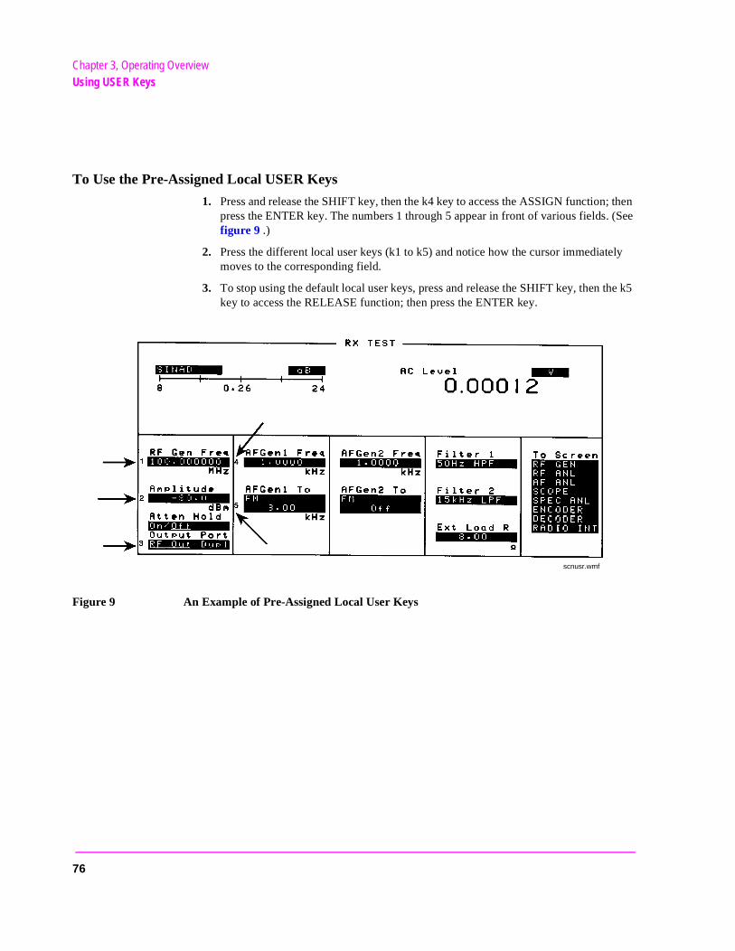
To Use the Pre-Assigned Local USER Keys
1. Press and release the SHIFT key, then the k4 key to access the ASSIGN function; then press the ENTER key. The numbers 1 through 5 appear in front of various fields. (See figure 9 .)
2. Press the different local user keys (k1 to k5) and notice how the cursor immediately moves to the corresponding field.
3. To stop using the default local user keys, press and release the SHIFT key, then the k5 key to access the RELEASE function; then press the ENTER key.
Figure 9 An Example of Pre-Assigned Local User Keys
scnusr.wmf
76
Chapter 3, Operating OverviewUsing USER Keys
To Assign Local USER Keys
1. Move the cursor to the field you want to assign a local user key to.
2. Press and release the SHIFT key, then the k4 key to access the ASSIGN function. Then press a local USER key (k1-k5). The user key number appears in front of the field you assigned it to.
Example of Assigning a Local USER Key
Use this example to assign local USER key k1 to the Filter 1 field in the RX TEST screen.
1. Access the RX TEST screen and position the cursor in front of the Filter 1 field.
2. Press and release the SHIFT key, then the k4 key to access the ASSIGN function; then press k1. A small 1 appears next to the field indicating that USER key k1 has been as-signed to it.
3. Move the cursor to any other field on the screen and press k1. The cursor immediately returns to the Filter 1 field. The field is also highlighted to change the entry using the CURSOR CONTROL knob or arrow keys.
To Release Local USER Keys
1. Display the screen containing the user key assignment to be removed.
2. Press and release the SHIFT key, then the k5 key to access the RELEASE function; then press the USER key (k1-k5).
77
Chapter 3, Operating OverviewUsing USER Keys
To Assign Global USER Keys
1. Move the cursor to the field you want to assign a global user key to.
2. Press and release the SHIFT key, then the k4 key to access the ASSIGN function. Then press SHIFT and a global USER key (k1’ - k3’). Unlike a local user key, the user key number does not appear at this field; instead, a prompt appears at the top of the screen confirming the key assignment.
Example of Assigning a Global USER Key
Use this example to assign global USER key k1’ to the AF Anl In field, and then access this field from the OSCILLOSCOPE screen.
1. Access the AF ANALYZER screen and position the cursor in front of the AF Anl In field.
2. Press and release the SHIFT key, then the k4 key to access the ASSIGN function.
3. Press SHIFT, k1’. Notice the prompt Global User key 1 assigned. at the top of the screen.
4. Access the OSCILLOSCOPE screen.
5. Press SHIFT, k1’.
AF Anl Input, FM Demod is displayed at the top of the screen (assuming the present input is set to FM Demod). To change the input, use the arrow keys (down-arrow or up-arrow), or press ENTER to access the Choices menu.
A field that is accessed using a global user key is only displayed at the top of the screen while it is being accessed. Moving the cursor to any other field in the screen causes the user key field to disappear until it is accessed again.
To Release Global USER Keys
1. Move the cursor to the field with the global user key assigned to it.
2. Press and release the SHIFT key, then the k5 key to access the RELEASE function. Then press SHIFT and the USER key to be released (k1’-k3’).
78
Chapter 3, Operating OverviewSetting an RF Generator/Analyzer Offset
en
Setting an RF Generator/Analyzer Offset
You can set a fixed frequency offset between the RF Generator and the RF Analyzer. This feature is convenient for testing radios with a fixed transmit/receive frequency offset.
To Set an RF Offset
1. Access the CONFIGURE screen.
2. Position the cursor in front of the RF Offset field, and press the Cursor Control knob, or press ENTER to turn the offset On or Off.
3. Select the (Gen)-(Anl) field and enter the frequency offset value.
Example of Setting an RF Offset
1. Access the CONFIGURE screen.
2. Set the RF Offset to On.
3. Enter an offset frequency ((Gen)-(Anl)) of 10 MHz.
4. Access the DUPLEX screen.
5. Set the Tune Mode to Manual. 1
6. Select the RF Gen Freq field, and rotate the Cursor Control knob to vary the RF Gen-erator’s frequency.
7. Notice that the Tune Freq value changes to maintain the 10 MHz difference betwethe generator and the analyzer.
1. Manual tuning is used in this example to prevent possible unexpected Tune Frequency changes during the procedure.
79
Chapter 3, Operating OverviewUsing Remote Control
Using Remote Control
The Test Set can be remotely controlled several ways:
• Using HP-IB control from a computer/controller. • Using IBASIC programs on memory cards. • Using an ASCII terminal connected to the serial port.
Using HP-IB Control
The Programmer’s Guide contains information on writing HP-IB control programs for the Test Set. Programming examples and a syntax listing provide general HP-IB operation guidelines.
Running IBASIC Programs from Memory Cards
The documentation shipped with HP 11807 software packages explains how to run those programs from memory cards. Refer to the Programmer’s Guide for detailed information on using memory cards with your own IBASIC programs.
80
Chapter 3, Operating OverviewUsing Remote Control
ter’s
/com-
Using an ASCII Terminal
Connecting an ASCII terminal to the serial port allows you to remotely operate the Test Set by entering characters that represent each front-panel control.
Before you can use this feature, you must first set the required serial port settings in the I/O CONFIGURE screen, and make any hardware connections.
The Serial Port connections are described in chapter 24, "Connector, Key, and Knob Descriptions".
To Configure for Serial Port Operation
1. Access the I/O CONFIGURE screen.
2. Set the Serial In field to Inst.
3. Set the IBASIC Echo field to On.
4. Set the Inst Echo field to On.
5. Set the remaining serial communications fields according to your terminal/compuserial communication requirements. These fields include: • Serial Baud • Parity • Data Length • Stop Length • Rcv Pace • Xmt Pace
6. The Test Set now responds to the equivalent characters sent to it by the terminalputer.
Equivalent Front-Panel Control Characters
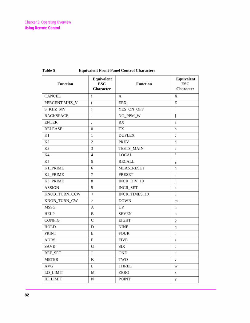
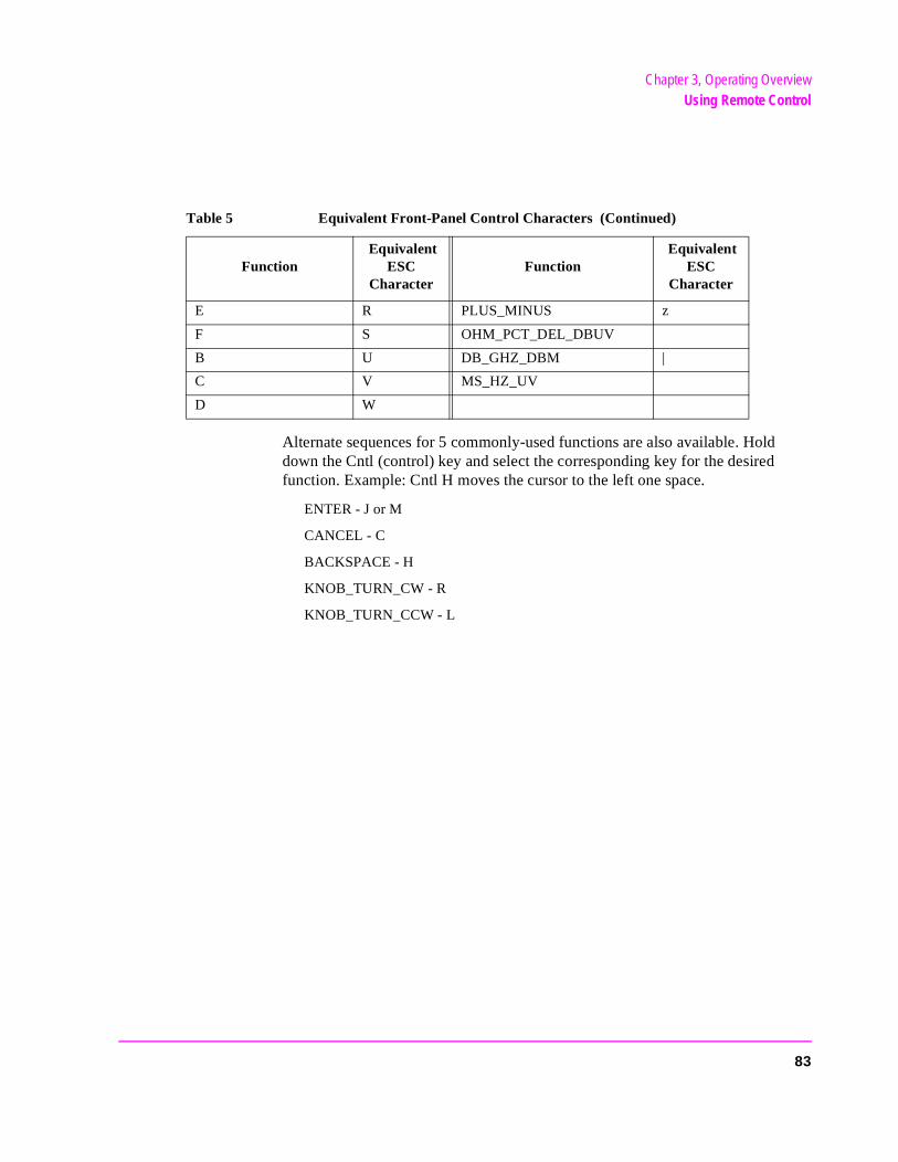
Table 5 on page 82 lists the terminal/computer keystrokes that equate to front-panel controls. Each sequence must be preceded by the Escape key.
For example, to remotely access the CONFIGURE screen, press the Esc key, then press the C key on your terminal/computer. Be sure to use upper-case C for this example.
81
Chapter 3, Operating OverviewUsing Remote Control
Table 5 Equivalent Front-Panel Control Characters
Function Equivalent
ESC Character
Function Equivalent
ESC Character
CANCEL ! A X
PERCENT MHZ_V ( EEX Z
S_KHZ_MV ) YES_ON_OFF [
BACKSPACE - NO_PPM_W ]
ENTER . RX a
RELEASE 0 TX b
K1 1 DUPLEX c
K2 2 PREV d
K3 3 TESTS_MAIN e
K4 4 LOCAL f
K5 5 RECALL g
K1_PRIME 6 MEAS_RESET h
K2_PRIME 7 PRESET i
K3_PRIME 8 INCR_DIV_10 j
ASSIGN 9 INCR_SET k
KNOB_TURN_CCW < INCR_TIMES_10 l
KNOB_TURN_CW > DOWN m
MSSG A UP n
HELP B SEVEN o
CONFIG C EIGHT p
HOLD D NINE q
PRINT E FOUR r
ADRS F FIVE s
SAVE G SIX t
REF_SET J ONE u
METER K TWO v
AVG L THREE w
LO_LIMIT M ZERO x
HI_LIMIT N POINT y
82
Chapter 3, Operating OverviewUsing Remote Control
Alternate sequences for 5 commonly-used functions are also available. Hold down the Cntl (control) key and select the corresponding key for the desired function. Example: Cntl H moves the cursor to the left one space.
ENTER - J or M
CANCEL - C
BACKSPACE - H
KNOB_TURN_CW - R
KNOB_TURN_CCW - L
E R PLUS_MINUS z
F S OHM_PCT_DEL_DBUV
B U DB_GHZ_DBM |
C V MS_HZ_UV
D W
Table 5 Equivalent Front-Panel Control Characters (Continued)
Function Equivalent
ESC Character
Function Equivalent
ESC Character
83

Chapter 3, Operating OverviewUsing Remote Control
84

4
Adjacent Channel Power Screen
This screen is used to measure Adjacent Channel Power. This is a measurement of the power of signals at a specific channel spacing above and below the RF Analyzer’s center frequency. This screen is accessed by selecting AD CH PWR from the To Screen menu.
85
Chapter 4, Adjacent Channel Power ScreenHow the Test Set Measures Adjacent Channel Power (ACP)
UT ng
el
mea-eat-atically
a-
How the Test Set Measures Adjacent Channel Power (ACP)
When you access this screen, the Test Set automatically starts a multi-step process for measuring ACP:
1. AF Generator 1 is turned off if the Carrier Ref field is set to Unmod.
2. The amplitude of the center frequency (Tune Freq) is measured to establish a reference.
3. AF Generator 1 is turned back on if it was previously turned off.
4. The power in each of the adjacent channels is analyzed.
5. Adjacent Channel Power is calculated and displayed. This value can be displayed as an absolute power level or as a ratio referenced to the center frequency’s level.
Which Input Port to Use. The TX Power measurement is used to calculate absolute Adjacent Channel Power. Since TX Power can only be measured using the RF IN/Oport, you must use this port to measure ACP Level. ACP Ratio can be measured usieither the RF IN/OUT or the ANT IN port.Measuring ACP on AM Transmitters. When measuring AM signals, the reference levmust be measured on an unmodulated carrier; so the Carrier Ref field must be set to Unmod. After the reference is measured, the power in the adjacent channels must besured with modulation. This requires the modulating signal to be turned off and on repedly as measurements are being calculated and displayed. Since the Test Set automturns AFGen1 on and off when the Carrier Ref field is set to Unmod, you must use AFGen1 and the AUDIO OUT port as the modulation source for making AM ACP mesurements.
86
Chapter 4, Adjacent Channel Power ScreenField Descriptions
y
Field Descriptions
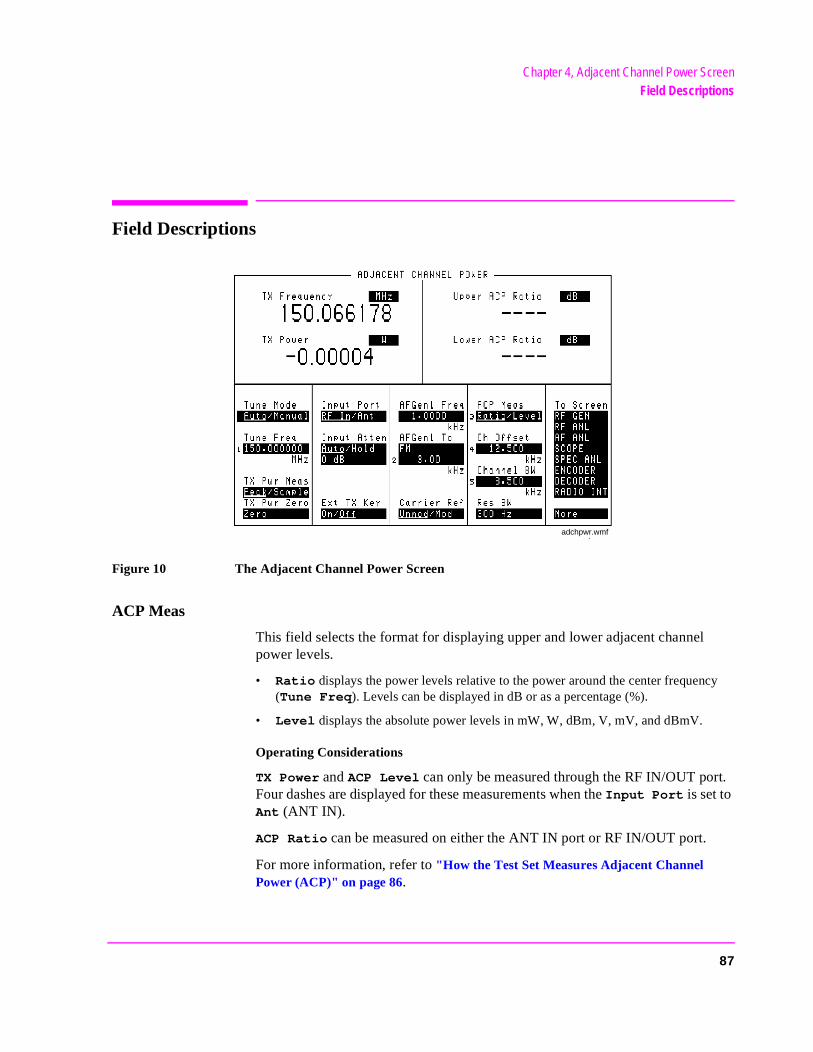
Figure 10 The Adjacent Channel Power Screen
ACP Meas
This field selects the format for displaying upper and lower adjacent channel power levels.
• Ratio displays the power levels relative to the power around the center frequenc(Tune Freq). Levels can be displayed in dB or as a percentage (%).
• Level displays the absolute power levels in mW, W, dBm, V, mV, and dBmV.
Operating Considerations
TX Power and ACP Level can only be measured through the RF IN/OUT port. Four dashes are displayed for these measurements when the Input Port is set to Ant (ANT IN).
ACP Ratio can be measured on either the ANT IN port or RF IN/OUT port.
For more information, refer to "How the Test Set Measures Adjacent Channel Power (ACP)" on page 86.
adchpwr.wmf
87
Chapter 4, Adjacent Channel Power ScreenField Descriptions
tor or
de
AFGen1 Freq
This field sets the frequency for the first audio frequency sinewave generator.
AFGen1 To
This field sets two values:
• The upper field determines whether the AFGen1 signal modulates the RF Generais output through the AUDIO OUT connector.
• The lower field sets the depth of modulation for FM and AM in kilohertz and amplitu(including Off) for audio out. The AUDIO OUT level is always in volts rms.
Operating Considerations
This is a priority control field. Accessing the RX TEST or TX TEST screen overrides any changes made to this field in other screens.
See Also
"Interaction Between Screens" on page 54
Carrier Ref
Use the carrier reference field to indicate whether the carrier (Tune Freq) being measured should be unmodulated or modulated when making the ACP reference measurement. (For more information, refer to "How the Test Set Measures Adjacent Channel Power (ACP)" on page 86.)
Operating Considerations• FM transmitters can be measured with the carrier modulated or unmodulated.• For AM transmitters, the carrier must be measured while unmodulated. AFGen1 and
the AUDIO OUT port must be used as the modulation source whenever Unmod is selected.
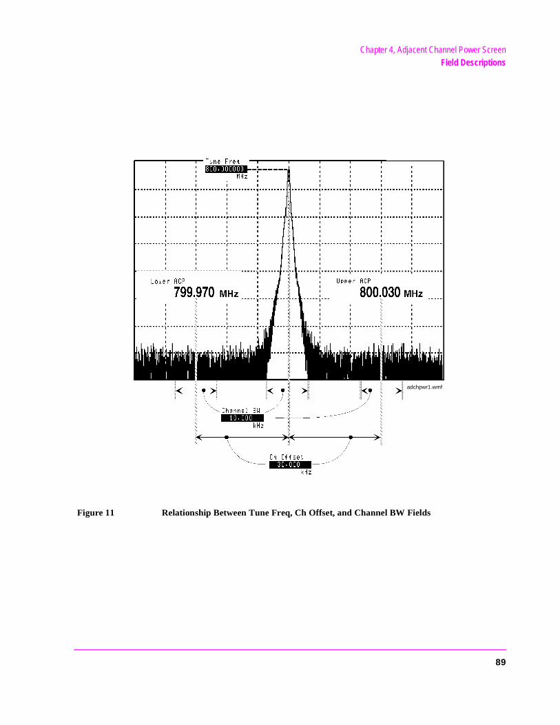
Channel BW
Use the channel bandwidth field to specify the bandwidth of the carrier and adjacent channels to be measured. (See figure 11 .)
88
Chapter 4, Adjacent Channel Power ScreenField Descriptions
Figure 11 Relationship Between Tune Freq, Ch Offset, and Channel BW Fields
adchpwr1.wmf
89
Chapter 4, Adjacent Channel Power ScreenField Descriptions
ati-
red at-
Ch Offset
Use the channel offset field to enter the frequency difference between the Tune Freq setting and the center of the adjacent channels you want to measure. This is an absolute value; only positive values can be entered. See figure 11 .
Ext TX key
This field controls a switch at the MIC/ACC connector. Use it to “key” an external transmitter.
See Also
"MIC/ACC" on page 514
Input Atten
Input Attenuation sets the amount of input attenuation for the RF IN/OUT andANT IN connectors. This function controls two settings:
• The upper field determines if you want the instrument to set the attenuation automcally (Auto), or if you want to set the value manually (Hold).
• The lower field displays the present attenuation value, and is used to set the desitenuation level when the upper area is set to Hold.
Operating Considerations
Input Attenuator autoranging can interfere with oscilloscope or signaling decoder operation under certain conditions. See "Input Atten," in chapter 17, on page 421 for additional information.
90
Chapter 4, Adjacent Channel Power ScreenField Descriptions
nnect f for ort.
ery TX
elow
Input Port
This field selects the RF IN/OUT or ANT IN port for making RF measurements. The RF IN/OUT port must be used for making TX Power or ACP Level measurements on this screen.
Operating Considerations
Power levels for each port are printed on the Test Set’s front panel. If the RFpower at the RF IN/OUT port exceeds allowable limits, a loud warning signalsounds and a message appears at the top of the screen. If this occurs, discothe RF power, press the MEAS RESET key, and allow the Test Set to cool ofapproximately two minutes before making any other measurements on this p
The ANT IN (antenna input) connector provides a highly-sensitive input for vlow level signals (such as “off the air” measurements). You cannot measure (RF) Power or ACP Level on this screen using the ANT IN port.
CAUTION: Connecting a signal of >200 mW to the ANT IN port can cause instrument damage(although internal protection circuits can typically withstand a short-duration signal of 1 or2 Watts).
If the overpower circuit is triggered (signified by a warning message at the top ofthe screen), remove the signal from the ANT IN port, and press the MEASRESET key or turn the Test Set off and on to reset it.
Lower and Upper ACP [Ratio:Level]
These two measurements display the amount of power in signals above and bthe Tune Freq signal. The level is displayed as a ratio (referenced to the power around the Tune Freq) or as an absolute value.
See Also
ACP Meas field description, on page 87
91
Chapter 4, Adjacent Channel Power ScreenField Descriptions
Res BW
The resolution bandwidth field selects the IF filter used when measuring the power of the carrier and the adjacent channels.
Operating Considerations
Using a narrower bandwidth filter (300 Hz) slows the measurement, but rejects carrier leakage and out of channel spurs. Using a wider bandwidth filter(1 kHz) speeds measurements, but may allow unwanted spurs and carrier leakage to be integrated into the measurement when measuring at the edges of the selected channel bandwidth.
Tune Freq
This field sets the center frequency for the RF signal to be analyzed.
See Also
Tune Mode field description (this page)
Tune Mode
This field selects Automatic or Manual tuning of the RF Analyzer.
Auto tuning causes the RF Analyzer to find the signal with the greatest amplitude >-36 dBm, and to set the Tune Frequency for that signal.
Manual tuning requires the operator to set the Tune Frequency for the RF signal to be analyzed.
Operating Considerations
Changing the Tune Mode also changes the RF frequency display. Automatic tuning enables the TX Frequency measurement. Manual tuning enables the TX Freq Error measurement.
92
Chapter 4, Adjacent Channel Power ScreenField Descriptions
TX Freq Error/TX Frequency
This measurement displays Transmitter Frequency Error or absolute Transmitter Frequency.
See Also
Tune Mode field description (this page)
TX Power
Transmitter Power measures RF power at the RF IN/OUT port.
Operating Considerations
Only the RF IN/OUT port can be used for measuring TX Power on this screen. When the Input Port is set to Ant, four dashes (- - - -) appear in place of digits for this measurement.
Use the Spectrum Analyzer to measure low-level RF power (≤200 mW) at the ANT IN port.
93
Chapter 4, Adjacent Channel Power ScreenField Descriptions
TX Pwr Zero
The transmitter power zero function establishes a 0.0000 W reference for measuring RF power at the RF IN/OUT port.
CAUTION: RF power must not be applied while zeroing. Set the RF Generator screen’s Amplitudefield to off to prevent internal cross-coupling into the power detector while zeroing.
Operating Considerations
When power is applied to the RF IN/OUT connector, the temperature of the internal circuitry increases. This can cause changes in the TX Power measurement when low power levels are measured immediately following high power measurements.
When alternately making high and low power measurements, always zero the power meter immediately before making the low power measurements; this provides the best measurement accuracy.
94
5
AF Analyzer Screen
95
Chapter 5, AF Analyzer ScreenBlock Diagram
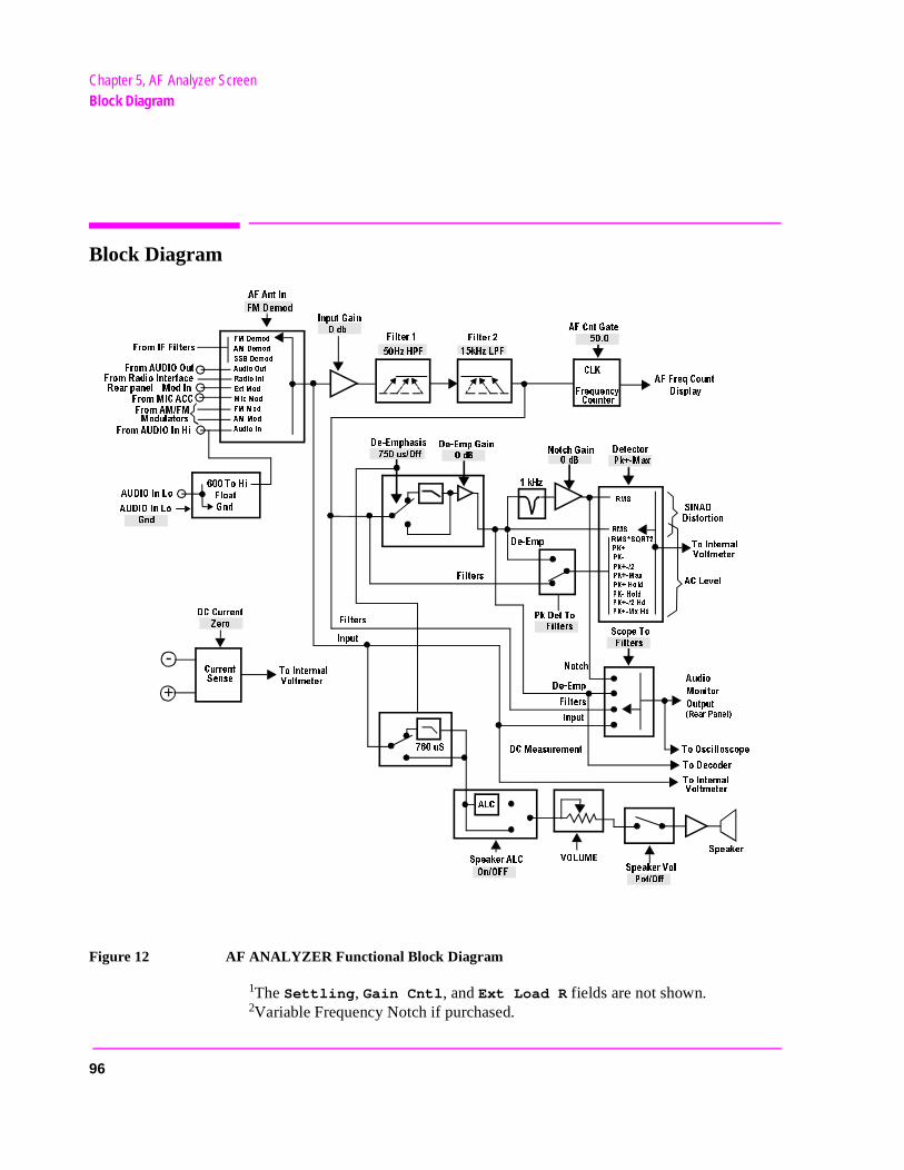
Block Diagram
Figure 12 AF ANALYZER Functional Block Diagram
1The Settling, Gain Cntl, and Ext Load R fields are not shown. 2Variable Frequency Notch if purchased.
$E %MPHASIS
$E %MP'AIN
.OTCH'AIN
D"
D"
!UDIO
-ONITOR
/UTPUT
2EAR0ANEL
4O/SCILLOSCOPE
4O$ECODER
4O)NTERNAL
6OLTMETER
3PEAKER
3PEAKER6OL
0OT/FF
6/,5-%
3PEAKER!,#
/N/&&
!,#
$#-EASUREMENT
.OTCH
$E %MP
&ILTERS
)NPUT
U3
)NPUT
&ILTERS
&ILTERS
$E %MP
0K$ET4O
&ILTERS
2-3
2-33124
0+
0+
0+
0+(OLD
0+ (OLD
0+ (D
0+ -X(D
0+ -AX
4O)NTERNAL
6OLTMETER
!#,EVEL
3).!$
$ISTORTION
&-$EMOD
!-$EMOD
33"$EMOD
!UDIO/UT
2ADIO)NT
%XT-OD
-IC-OD
&--OD
!--OD
!UDIO)N
&ROM)&&ILTERS
&ROM!5$)//UT
&ROM2ADIO)NTERFACE
2EARPANEL -OD)N
&ROM-)#!##
&ROM!-&-
-ODULATORS
&ROM!5$)/)N(I
2-3
4O)NTERMAL
6OLTMETER
#URRENT
3ENSE
-
+
$##URRENT
:ERO
!5$)/)N,O
!5$)/)N,O
'ND
'ND
4O(I
&LOAT
US/FF
$ETECTOR
0K -AX
#,+
&REQUENCY
#OUNTER
!&&REQ#OUNT
$ISPLAY
!&#NT'ATE
&ILTER
(Z(0&
K(Z,0&
&ILTER
)NPUT'AIN
DB
!&!NT)N
&-$EMOD
3COPE4O
&ILTERS
K(Z
96
Chapter 5, AF Analyzer ScreenBlock Diagram
Field Descriptions
AC Level
This measurement displays either rms potential (voltage) or audio power (Watts or dBm).
Operating Considerations
When the unit-of-measure is changed to measure AF power, the external load resistance must be specified. Refer to theExt Load R field description, on page 102.
The input for the ac level measurement on this screen is always the AUDIO IN connectors.
See Also
"Entering and Changing Numbers" on page 63
AF Anl In
The audio frequency analyzer input selects the input for the analyzer. When selected, this field displays a list of choices.
Signals can be analyzed from three different types of inputs:
• The output of the AM, FM, or SSB demodulators.
• The AUDIO IN, RADIO INTERFACE, MODULATION INPUT, MIC/ACC, and AUDIO OUT connectors.
• The signal present at the AM or FM modulators for the RF Generator.
See Also
"Interaction Between Screens" on page 54 "Displaying Measurements" on page 57
97

Chapter 5, AF Analyzer ScreenBlock Diagram
en1
AF Cnt Gate
Audio frequency counter gate specifies how long the AF counter samples the signal before displaying the frequency. Specifying a shorter gate time may enable you to see frequency fluctuations that might not be seen using a longer gate time.
AF Freq
This is the default measurement for this measurement field. Selecting this field displays the following measurement choices:
SINAD
Distortion
SNR (Signal to Noise Ratio)
AF Frequency
DC Level
Current - DC only Operating Considerations
This is a priority control field. Accessing the RX TEST or TX TEST screen overrides any changes made to this field in other screens.
SNR Operation• Selecting SNR turns off the other audio measurement. • The RF Generator and AFGen1 must be set up to provide the radio’s carrier. AFG
is automatically turned on and off repeatedly during this measurement.• AFGen2 must be turned off. • The radio’s receiver’s audio output must be connected to the AUDIO IN port (set
the AF Anl In field to Audio In).
See Also
"Interaction Between Screens" on page 54"Displaying Measurements" on page 57
98
Chapter 5, AF Analyzer ScreenBlock Diagram
ound.
put
DIO
AM Depth
This field displays the percent depth of modulation of the AM signal. The field is only visible when the AF ANL In field is set to AM MOD or AM DEMOD
Audio In Lo
This field sets the AUDIO IN LO connector’s state.
• Gnd causes the center pin of the connector to be connected directly to chassis gr
• Float isolates the center pin of the connector from ground, providing a floating into the AF Analyzer.
• 600 To Hi establishes a 600-ohm impedance between the center pins of the AUIN LO and AUDIO IN HI connectors. Also, the Ext Load R field is removed, since the load is now fixed to 600 ohms.
Current
The Current field is found by selecting the SINAD field on the Test Set display of the AF ANALYZER screen. This field only displays the DC current measured at the DC input port on the back of the Test Set. Any offset can be removed by selecting Zero from the DC Current field.
DC Current
DC current measurement zero removes any measurement offset present before making a dc-current measurement. The measurement is zeroed by selecting Zero, and pressing the ENTER key or the Cursor Control knob.
NOTE: The current source must be disconnected before zeroing for accurate operation.
See Also
"DC CURRENT MEASUREMENT" on page 511"SINAD, Distortion, SNR, AF Frequency, DC Level, DC Current" on page 60Chapter 24, "Connector, Key, and Knob Descriptions"
99
Chapter 5, AF Analyzer ScreenBlock Diagram
DC Level
This field displays the DC voltage entering at the DC input port on the back of the Test Set.
De-Emp Gain
De-emphasis gain displays and selects the desired AF analyzer de-emphasis amplifier gain.
See Also
Gain Cntl field description, on page 103
De-Emphasis
This setting selects or bypasses the 750 ms de-emphasis networks in the audio analyzer and speaker circuitry.
See Also
"Interaction Between Screens" on page 54
Distn
This field displays the percent of distortion. The Distortion measurement is only for a 1 kHz signaling tone.
100
Chapter 5, AF Analyzer ScreenBlock Diagram
e
eset. same
eset. same
ET
value ferent
Detector
This setting selects the type of detector used when measuring and displaying AF signal levels.
Detector Types• RMS displays the RMS value of signals. • displays the RMS value of a signal multiplied by . • Pk+ displays the positive peak value. • Pk− displays the negative peak value. • Pk±/2 adds the positive and negative peak values, and divides the sum by 2. • Pk±Max compares the positive and negative peaks and displays the greater valu
(polarity is not indicated). • Pk+ Hold displays and holds the positive peak value until the measurement is r
To reset, press the MEAS RESET key, select a different detector, or re-select thedetector.
• Pk− Hold displays and holds the negative peak value until the measurement is rTo reset, press the MEAS RESET key, select a different detector, or re-select thedetector.
• Pk±/2 Hold divides the sum of the positive and negative peak values by 2, anddisplays the value until the measurement is reset. To reset, press the MEAS RESkey, select a different detector, or re-select the same detector.
• Pk±Mx Hold compares the positive and negative peaks and displays the greater until the measurement is reset. To reset, press the MEAS RESET key, select a difdetector, or re-select the same detector.
See Also
"Interaction Between Screens" on page 54
2
101
Chapter 5, AF Analyzer ScreenBlock Diagram
Ext Load R
External Load Resistance is used to calculate and display AF power. Power is calculated using the voltage measured at the AUDIO IN connections and the resistance value you enter into this field.
Operating Considerations
This field is not displayed when the Audio In Lo field is set to 600 To Hi; the load resistance is internally fixed to 600 ohms.
See Also
AC Level field description, on page 97Audio In Lo field description, on page 99
Filter 1 and Filter 2
Filters 1 and 2 select a variety of standard and optional filters. Selecting either field lists the choices available for that field.
FM Deviation
This is the default measurement for this field. The FM Deviation field displays the frequency deviation between the FM signal and the carrier. The FM Deviation measurement field is only displayed when the AF Anl In field is set to FM Demod or FM Mod.
See Also
AF Anl In field description, on page 97"Displaying Measurements" on page 57
102
Chapter 5, AF Analyzer ScreenBlock Diagram
Gain Cntl
AF Analyzer Gain Control specifies whether the AF Analyzer’s gain settings are controlled automatically by AF autoranging (Auto), or by manual control (Hold).
The following settings are affected by AF autoranging:
• Input Gain • De-Emp Gain • Notch Gain
Operating Considerations
The normal mode of operation for the Gain Cntl field is Auto, allowing the instrument to adjust the AF gain settings for optimum measurement accuracy.
This field can be set to Hold to disable the autoranging routines to increase measurement speed. However, this requires you to select the desired gain settings manually for each measurement.
NOTE: Decoder and Oscilloscope Interference: The AF autoranging function (Auto) takes a small amount of time to determine the attenuation settings for the AF Analyzer. If you are decoding an encoded signal, and your transmitter begins sending encoded information the instant it transmits, the initial encoded information may not be decoded during the autoranging process.Use the Auto setting to establish the initial gain settings while the encoded signal is first being decoded, and then select Hold during the decoding process to retain the gain settings. The decoder should capture all encoded information the next time you transmit the signal.
Input Gain
This field displays and selects the gain of the AF Analyzer’s input amplifier. Refer to the Gain Cntl field information.
103
Chapter 5, AF Analyzer ScreenBlock Diagram
s you l
Notch Freq
This field sets the center frequency for the variable frequency notch filter.1 It is typically used for distortion and SINAD measurements at frequencies below or above the standard 1 kHz notch filter.
This field is not displayed if your Test Set does not have this feature.
Operating Considerations
When the Notch Coupl field on the CONFIGURE screen is set to AFGen1, this filter and the AFGen1 Freq field match their settings. A warning message is then displayed if you attempt to set the AFGen1 Freq value outside the 300 Hz to 10 kHz range of this filter. When the Notch Coupl field is set to None, this filter and AFGen1 Freq operate independently.
1. Optional on some Test Sets
Notch Gain
This field displays and selects the gain of the AF Analyzer’s notch filter amplifier. This amplifier is only used for making SINAD and distortion measurements. (Refer to the Gain Cntl field information.)
Pk Det To
Peak Detector To selects the signal source for the peak detectors. This allowto bypass certain sections of the AF analyzer’s circuitry when making ac-levemeasurements.
See Also
Figure 12, "AF ANALYZER Functional Block Diagram," on page 96.
104
Chapter 5, AF Analyzer ScreenBlock Diagram
de ng
ncy
d
Scope To
Oscilloscope To selects the signal source for the Oscilloscope. This allows you to bypass certain sections of the AF analyzer’s circuitry when viewing and measuring a signal. It also allows you to select measurement paths that incluadditional gain stages, improving the oscilloscope’s resolution when measurilow-level signals.
See Also
Figure 12, "AF ANALYZER Functional Block Diagram," on page 96
Settling
This field selects the settling time for making AF measurements. Lower frequesignals require additional settling time (Slow). Higher frequency measurements require less settling time (Fast).
Operating Considerations
Use Slow for ≤200 Hz signals. Use Fast for >200 Hz signals.
If the signal being measured is a composite of different frequencies above anbelow 200 Hz, select the appropriate filtering to analyze the desired signal component.
105
Chapter 5, AF Analyzer ScreenBlock Diagram
en1
the
SINAD
This measurement field is used to select and display any one of the following measurements:
SINAD
Distortion
SNR (Signal to Noise Ratio)
AF Frequency
DC Level
Current - DC only Operating Considerations
This is a priority control field. Accessing the RX TEST or TX TEST screen overrides any changes made to this field in other screens.
SNR Operation
• Selecting SNR turns off the other audio measurement.
• The RF Generator and AFGen1 must be set up to provide the radio’s carrier. (AFGis automatically turned on and off repeatedly during this measurement.)
• AFGen2 must be turned off.
• The radio’s receiver’s audio output must be connected to the AUDIO IN port (setAF Anl In field to Audio In).
See Also
"Interaction Between Screens" on page 54
SNR
The SNR field is found by selecting the SINAD field on the Test Set display of the AF ANALYZER screen.This field displays the signal to noise ratio of the input audio signal.
106
Chapter 5, AF Analyzer ScreenBlock Diagram
Speaker ALC
Speaker Automatic Level Control enables/disables the ALC function for the instrument’s internal speaker. When On is selected, the speaker volume is independent of the signal level being measured. When Off is selected, the speakervolume is dependent on the signal level being measured.
Speaker Vol
Speaker Volume enables/disables the instrument’s internal speaker. When Pot is selected, the VOLUME control knob operates normally. When Off is selected, the speaker is disconnected.
TX Freq Error/ TX Frequency
This measurement area is used to display transmitter frequency error or transmitter frequency. The type of measurement displayed depends on the Tune
Mode setting in the TX TEST, DUPLEX TEST, or RF ANALYZER screen.
See Also
"Displaying Measurements" on page 57
107
Chapter 5, AF Analyzer ScreenBlock Diagram
TX Power
Transmitter Power measures RF power at the RF IN/OUT port.
Operating Considerations
Maximum signal levels at each port are printed on the front panel.
Only the RF IN/OUT port can be used for measuring TX Power on this screen. When the Input Port is set to Ant, four dashes (- - - -) appear in place of digits for this measurement.
Use the Spectrum Analyzer to measure low-level RF power (≤200 mW) at the ANT IN port.
CAUTION: Connecting a signal of >200 mW to the ANT IN port can cause instrument damage (although internal protection circuits can typically withstand a short-duration signal of 1 or 2 Watts).
If the overpower circuit is triggered (signified by a warning message at the top of the screen), remove the signal from the ANT IN port, and press the MEAS RESET key or turn the Test Set off and on to reset it.
See Also
Input Port field description, on page 422TX Power field description, on page 426TX Pwr Zero field description, on page 427
108
6
Call Processing Subsystem
109
Chapter 6, Call Processing SubsystemDescription of the Call Processing Subsystem
iver to
f a
s bile
l
Description of the Call Processing Subsystem
The Call Processing Subsystem, which comprises five call processing screens, allows the Test Set to simulate a cellular base station. The Call Processing Subsystem provides, through host firmware control, the specific signals and protocol messages necessary to automatically establish and maintain a cellular link between the Test Set and a cellular phone (mobile station).
Once the link is established the operator can exercise the call processing functions of the mobile station, such as
• the decoding of orders from the base station, such as orders to retune the transcea new channel, to alert the mobile station user to an incoming call, to adjust the transceiver output power level, or to release the mobile station upon completion ocall.
• the encoding of signaling information for transmission to the base station, such adialed digits for call origination, disconnect signal at the completion of a call, or moidentification number.
In addition, when the link is established the Test Set performs the following functions automatically:
• measures some of the basic RF characteristics of the mobile station’s transmittedcarrier, such as; transmitter power, frequency accuracy, and modulation deviation
• decodes and displays various reverse control channel and reverse voice channesignaling messages
When sending forward control channel and forward voice channel messages, you can set the bit pattern to an industry standard or to a pattern of your choice. The ability to set the bit patterns gives the operator the opportunity to interject errors into the signaling message, and test the mobile station’s ability to find these errors.
110
Chapter 6, Call Processing SubsystemDescription of the Call Processing Subsystem
e
d as est the ation res
voice iver
le ile
ically
ator .
and
Operational Overview
The Test Set simulates a cellular base station by using its hardware and firmware resources to initiate and maintain a link with a mobile station. Unlike a real base station, the Test Set has only one transceiver (its signal generator and RF/AF analyzer) and can support only one mobile station at a time. This means that the Test Set’s transceiver can be configured as either a control channel or a voicchannel, but not both simultaneously.
To establish a link with a mobile station the Test Set’s transceiver is configurea control channel. Once a link has been established and the user wishes to tmobile station on a voice channel, the Test Set sends the appropriate informto the mobile station on the control channel and then automatically re-configuits transceiver to the voice channel assigned to the mobile station. Once the channel link is terminated, the Test Set automatically re-configures its transceback to being a control channel.
Handoffs are accomplished in a similar manner. When a handoff is initiated whion a voice channel, the Test Set sends the necessary information to the mobstation on the current voice channel. At the proper time, the Test Set automatre-configures its transceiver to the new voice channel.
Figure 13, "Call Processing State Diagram," on page 112 illustrates the primary call processing functions available in the Call Processing Subsystem. Each box represents a call processing state and includes the measurement informationavailable while in that state. Each box also includes the name of the annuncion the call processing screen that will be lit while in that call processing stateEvents which trigger transitions between the various states are shown on the diagram. Events which are initiated from the Test Set are shown in solid linesevents which are initiated from the mobile station are shown in dashed lines.
111
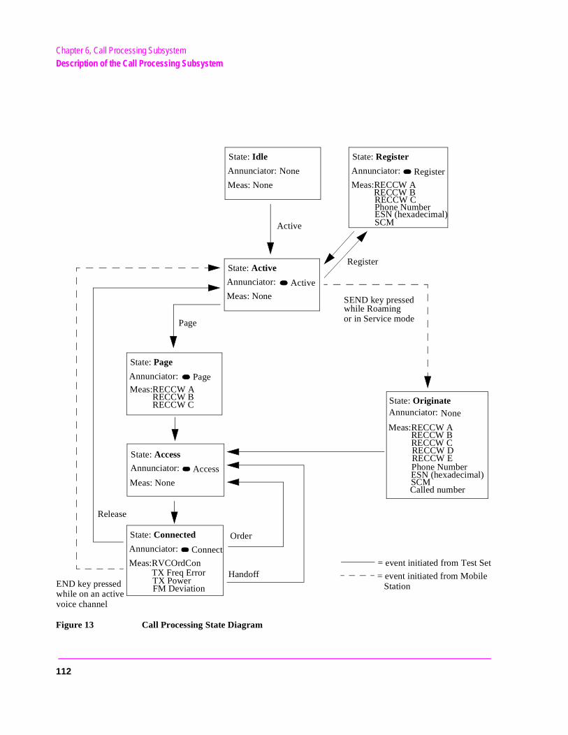
Chapter 6, Call Processing SubsystemDescription of the Call Processing Subsystem
Figure 13 Call Processing State Diagram
State: Active
Meas: None
Annunciator: Active
Active
State: Idle
Meas: None
Annunciator: None
State: Register
Meas:RECCW A
Annunciator: Register
Phone NumberESN (hexadecimal)
Register
END key pressedwhile on an activevoice channel
State: Originate
SEND key pressedwhile Roamingor in Service mode
State: Page
Annunciator: PageMeas:RECCW A
RECCW BRECCW C
Page
State: Access
Meas: None
Annunciator: Access
State: Connected
Meas:RVCOrdCon
Annunciator: Connect
TX Freq ErrorTX PowerFM Deviation
Meas:RECCW ARECCW BRECCW CRECCW DRECCW E
Release
Handoff
Phone NumberESN (hexadecimal)SCMCalled number
RECCW BRECCW C
SCM
Annunciator: None
Order
= event initiated from Test Set
= event initiated from Mobile Station
112
Chapter 6, Call Processing SubsystemDescription of the Call Processing Subsystem
e
een e fre-ing n. The re-
the l pro-m this
ard
me-
n the
Accessing the Call Processing Subsystem’s Screens
The Call Processing Subsystem screens are accessed by selecting CALL CNTL from the To Screen menu on the Test Set’s CRT (you may have to choose thMore choice to display the CALL CNTL choice).
Call Processing Subsystem’s Screens
The Call Processing Subsystem consists of five screens.
• The CALL CONTROL is the primary Call Processing Subsystem screen. This scrcontains the fields used to configure the Test Set’s parameters such as SAT Tonquency, control channel number, and system identification number. Call processfunctions such as registration, page, and handoff can be activated from this screetransmit power of the mobile station can be set from this screen. Data messagesceived from the mobile station are displayed on this screen.
• The CALL DATA screen displays the decoded signaling messages received frommobile station on the reverse control channel and the reverse voice channel. Calcessing functions such as registration, page, and handoff can also be activated froscreen. The transmit power of the mobile station can be set from this screen.
• The CALL BIT screen allows the advanced user to modify the contents of the forwcontrol channel and forward voice channel messages.
• The CALL CONFIGURE screen contains the fields used to configure various paraters related to the Call Processing Subsystem, such as CMAX, Detector, and Input Att.
NOTE: The ANALOG MEAS screen is used to make analog RF and audio measurements omobile station while a link is active.
113
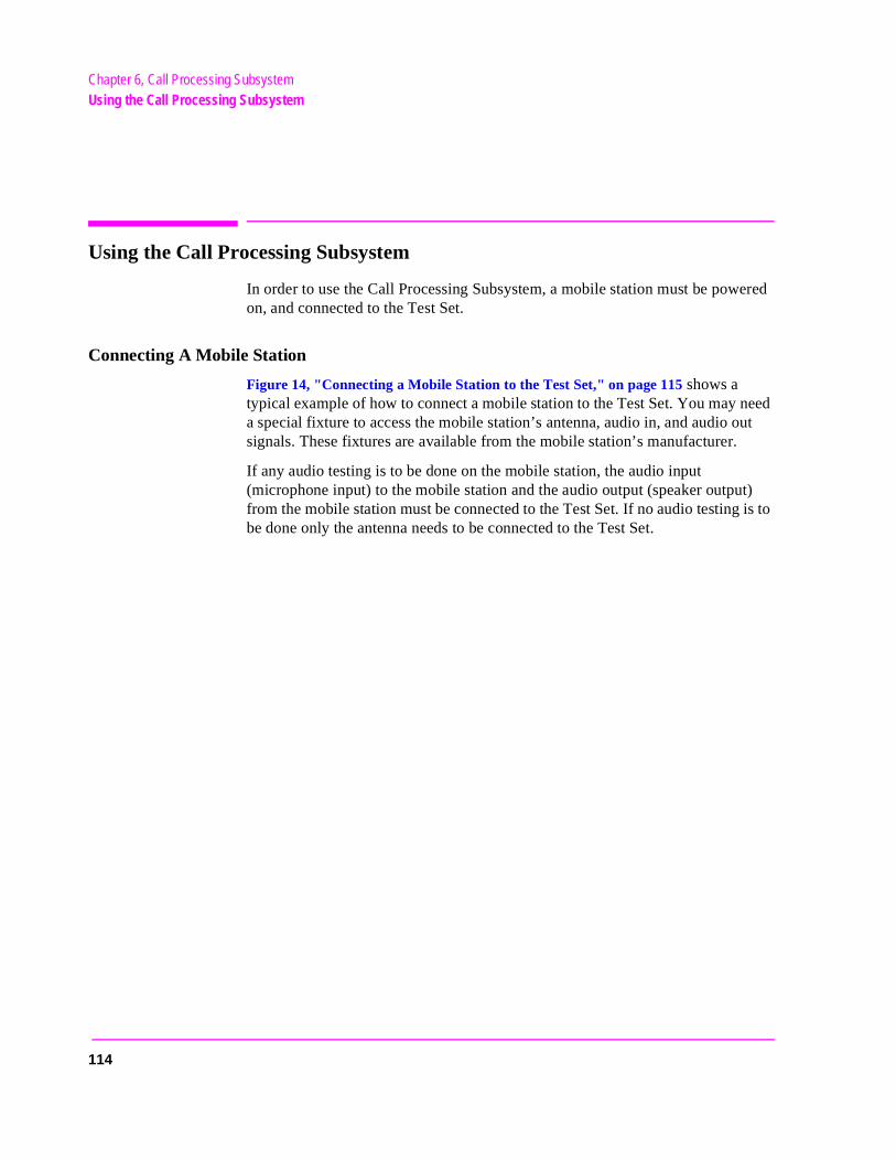
Chapter 6, Call Processing SubsystemUsing the Call Processing Subsystem
ut
t) is to
Using the Call Processing Subsystem
In order to use the Call Processing Subsystem, a mobile station must be powered on, and connected to the Test Set.
Connecting A Mobile Station
Figure 14, "Connecting a Mobile Station to the Test Set," on page 115 shows a typical example of how to connect a mobile station to the Test Set. You may need a special fixture to access the mobile station’s antenna, audio in, and audio osignals. These fixtures are available from the mobile station’s manufacturer.
If any audio testing is to be done on the mobile station, the audio input (microphone input) to the mobile station and the audio output (speaker outpufrom the mobile station must be connected to the Test Set. If no audio testingbe done only the antenna needs to be connected to the Test Set.
114
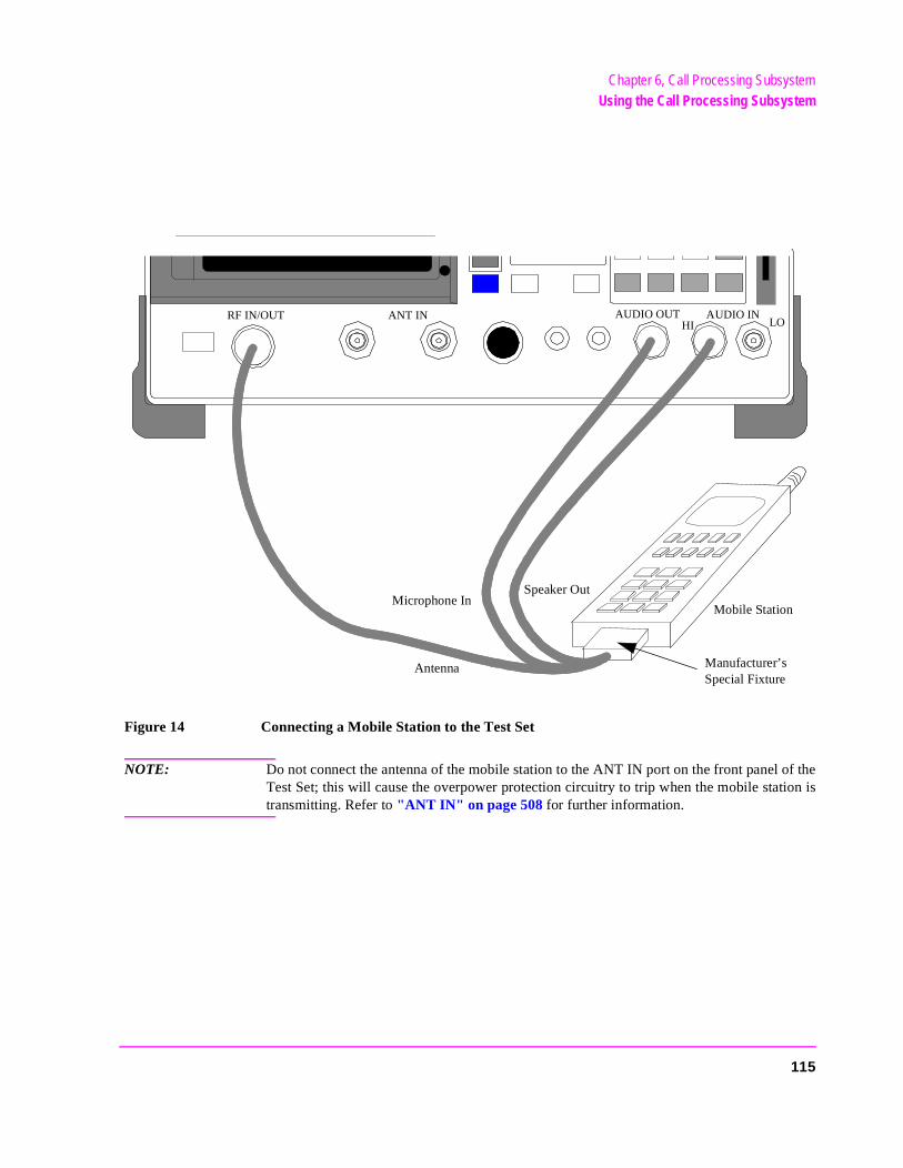
Chapter 6, Call Processing SubsystemUsing the Call Processing Subsystem
Figure 14 Connecting a Mobile Station to the Test Set
NOTE: Do not connect the antenna of the mobile station to the ANT IN port on the front panel of theTest Set; this will cause the overpower protection circuitry to trip when the mobile station istransmitting. Refer to "ANT IN" on page 508 for further information.
ANT IN
Manufacturer’s Special Fixture
AUDIO OUTRF IN/OUT AUDIO INLOHI
Antenna
Speaker OutMicrophone In
Mobile Station
115
Chapter 6, Call Processing SubsystemUsing the Call Processing Subsystem
s d to
t in
Mobile Station Audio Out Impedance
If the mobile station’s speaker is disconnected when using the manufacturer’special fixture, the user must ensure that the proper load impedance is appliethe audio output of the mobile station. The special fixtures supplied by the manufacturer of the mobile station may or may not terminate the audio outpuits proper load impedance. Refer to the manufacturer’s documentation for information on the termination supplied by the special fixture.
If a load impedance must be supplied, then it can be placed across the AUDIO IN connector. Refer to "AUDIO IN" on page 509 and chapter 5, "AF Analyzer Screen," on page 95, for further information.
600 Ohm Impedance
Some industry standards require the audio out of the mobile station to be terminated in 600 ohms for testing purposes. The AUDIO IN connector of theTest Set can be terminated in 600 ohms internally. Refer to "AUDIO IN" on page 509 and chapter 5, "AF Analyzer Screen," on page 95, for further information.
116
Chapter 6, Call Processing SubsystemUsing the Call Processing Subsystem
Generalized Procedures Using the Call Processing Subsystem
For general procedures for using the Call Processing Subsystem, see the following sections:
• "Conditioning the Test Set for Call Processing" on page 130• "Configure the Test Set" on page 131• "Turn On The Test Set’s Control Channel" on page 132• "Register a Mobile Station" on page 132• "Page a Mobile Station" on page 133• "Handoff a Mobile Station to a New Voice Channel" on page 135• "Release A Mobile Station" on page 135• "Change the Transmit Power Level of a Mobile Station" on page 136• "Originate a Call from a Mobile Station" on page 137• "Send an Alert Order to a Mobile Station" on page 138• "Changing the Content of a Message Field" on page 190• "Selecting The Message Content Generation Method" on page 187• "To Make an RF Sensitivity Measurement" on page 196• "To Make an FM Hum and Noise Measurement" on page 197
117
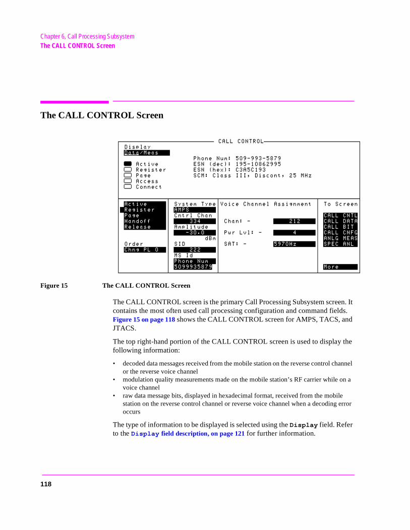
Chapter 6, Call Processing SubsystemThe CALL CONTROL Screen
hannel
n a
le error
The CALL CONTROL Screen
Figure 15 The CALL CONTROL Screen
The CALL CONTROL screen is the primary Call Processing Subsystem screen. It contains the most often used call processing configuration and command fields. Figure 15 on page 118 shows the CALL CONTROL screen for AMPS, TACS, and JTACS.
The top right-hand portion of the CALL CONTROL screen is used to display the following information:
• decoded data messages received from the mobile station on the reverse control cor the reverse voice channel
• modulation quality measurements made on the mobile station’s RF carrier while ovoice channel
• raw data message bits, displayed in hexadecimal format, received from the mobistation on the reverse control channel or reverse voice channel when a decodingoccurs
The type of information to be displayed is selected using the Display field. Refer to the Display field description, on page 121 for further information.
118
Chapter 6, Call Processing SubsystemThe CALL CONTROL Screen
s
orce ect). If ld
t is
t lit,
is not
, the
[] Access
When lit, the Access annunciator indicates the Test Set is signaling the mobile station with command information on the forward voice channel. This is a transitory state.
The Test Set’s speaker is turned off when in the access state. This is done toeliminate any possible audio feedback which may occur if the mobile station’microphone is open.
Active
This field is used to turn on the forward control channel of the Test Set or to fa return to the active state from any other state (register, page, access, connthe forward control channel of the Test Set is already active, selecting this fiewill deactivate and then reactivate the control channel.
[] Active
When lit, the Active annunciator indicates the control channel of the Test Seturned on.
If this annunciator is lit, the base station is transmitting system parameter overhead messages on the assigned control channel. If the annunciator is nothe base station is not active.
NOTE: The Test Set may still be outputting a modulated RF carrier but the Test Set’s firmwareactive and no communication can occur between a mobile station and the Test Set.
AF Freq
The AF Freq field is displayed only when the Display field is set to Meas.
This field displays the audio frequency of the demodulated FM signal being transmitted by the mobile station. Four dashes (----) indicate that no audio frequency is present to measure. A numeric value would only be displayed when the Test Set’s Connected annunciator is lit (connected state).
Amplitude
This field is used to set the output power of the Test Set’s transmitter (that isoutput power of the Test Set’s RF Generator).
119
Chapter 6, Call Processing SubsystemThe CALL CONTROL Screen
the Test e
hich nnel
Called Number:
This field displays the called phone number, in decimal form, received from the mobile station on the reverse control channel when the mobile station originates a call. The Called Number: field is displayed only when the Display field is set to Data and a reverse control channel message has been decoded when the mobile originates a call.
Chan:
Chan: is divided into two fields:
• The left-hand field displays the voice channel number assignment being used by Test Set and the mobile station. A numeric value would only be displayed when theSet’s Connected annunciator is lit (connected state). A “-” is displayed if a mobilstation is not actively connected on a voice channel.
• The right-hand field (highlighted field) is used to enter the voice channel number wwill be assigned to the mobile station by the Test Set as either an initial voice chaassignment or as a handoff voice channel assignment.
Cntl Channel
This field is used to set the control channel number used by the Test Set.
The Cntl Channel field is an immediate action field. That is, whenever the Cntl Channel field is changed, the change is reflected immediately in the physical configuration of the Test Set (the control channel is immediately de-activated, reconfigured, and then re-activated to reflect the change) and causes an immediate change to the current state of the Call Processing Subsystem (the state is set to Active).
[] Connect
When lit, the Connect annunciator indicates that the mobile station is connected to the Test Set on a voice channel.
120
Chapter 6, Call Processing SubsystemThe CALL CONTROL Screen
Test
tem
e layed.
e
are is- (hex), on-inu-
chan-
n’s
the s
NOTE: When the CALL CONTROL screen is displayed and the Call Processing Subsystem is in the connected state (Connect annunciator is lit), the Test Set constantly monitors the mobile station’s transmitted carrier power. If the power falls below 0.0005 Watts the Set will terminate the call and return to the active state (Active annunciator is lit). The mobile station’s transmitted carrier power is monitored on all Call Processing Subsysscreens except the ANALOG MEAS screen.
If the Test Set is in the connected state (Connect annunciator is lit) and achange is made to the Cntl Channel field the connected state will be lost.
Display
This field is used to select the type of mobile station information to be displayed in the upper right-hand portion of the CALL CONTROL screen:
• Select Data to display information received from the mobile station on the reversecontrol channel or reverse voice channel. If the data message(s) received from thmobile station can be correctly decoded, the decoded message contents are dispIf the data messages cannot be correctly decoded, the raw data message bits ardisplayed in hexadecimal format. Figure 16 on page 122 shows the layout of the CALL CONTROL screen when a decoding error has occurred.
The decoded order confirmation message, origination message, and order messageavailable from the reverse control channel. The following pieces of information are dplayed when these messages are properly decoded: phone number, ESN (dec), ESNthe decoded Station Class Mark (SCM), and the called number. The decoded SCM csists of: the mobile station power class (Class I, II, or III), the transmission type (contous/discontinuous), and the transmission bandwidth (20 MHz or 25 MHz).
• The decoded Order Confirmation Message is available from the reverse voice nel.
• Select Meas to display modulation quality measurements made on the mobile statioRF carrier while on a voice channel.
For system types AMPS, TACS, and JTACS four characteristics of the RF carrier are measured: TX Freq Error, TX Power, FM Deviation, and AF Frequency. When set toMeas display, the AF Analyzer’s settings are 300 Hz HPF, 15 kHz LPF, De-EmphasiOff, PK+ detector. The Meas information is available only when the Test Set’s Connect annunciator is lit (connect state). Refer to the individual field descriptions for further information. Figure 17 on page 122 shows the layout of the CALL CONTROL screen when Meas is selected.
•
121
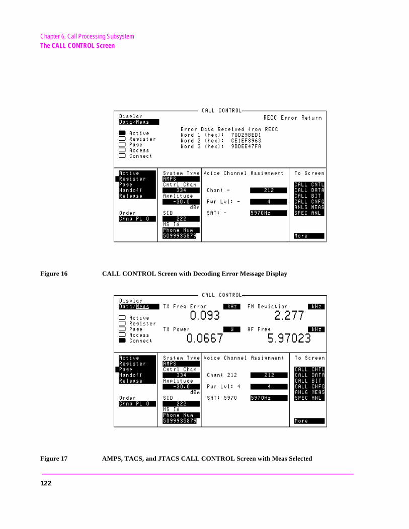
Chapter 6, Call Processing SubsystemThe CALL CONTROL Screen
Figure 16 CALL CONTROL Screen with Decoding Error Message Display
Figure 17 AMPS, TACS, and JTACS CALL CONTROL Screen with Meas Selected
122
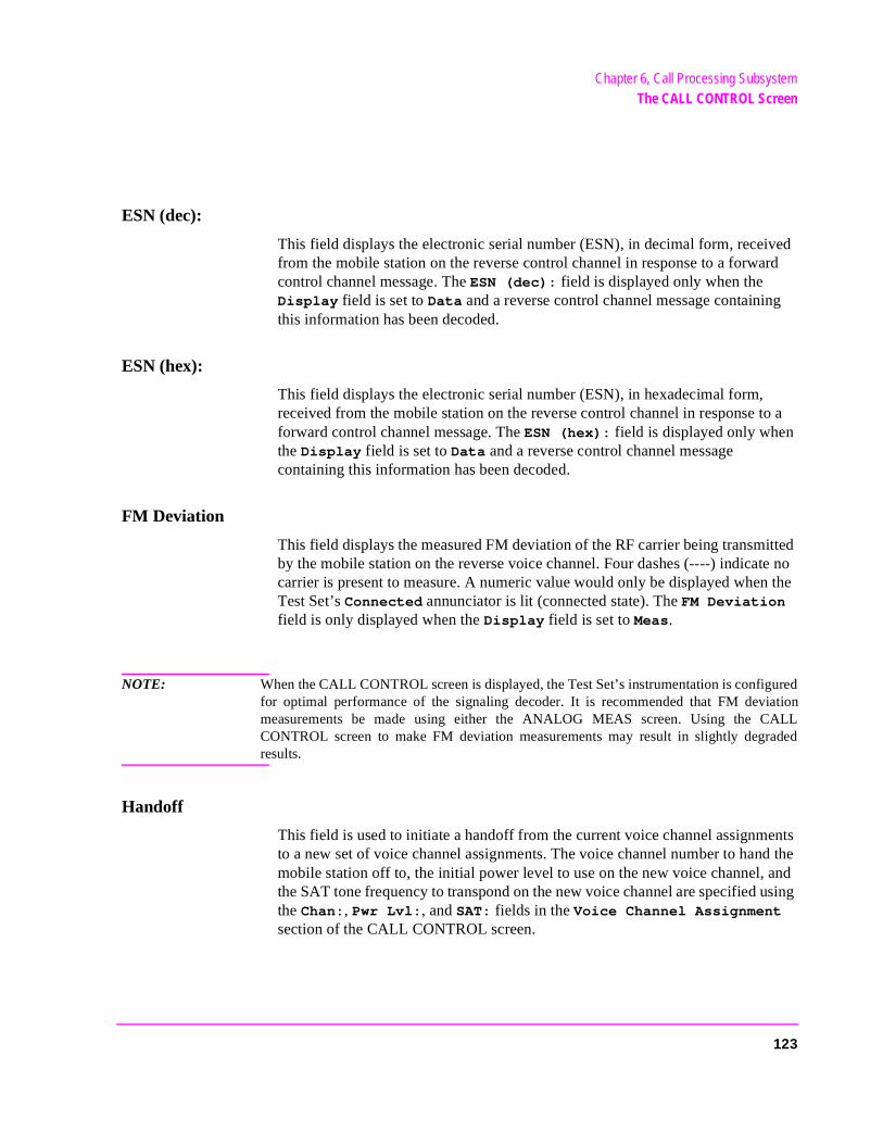
Chapter 6, Call Processing SubsystemThe CALL CONTROL Screen
uredationALLaded
ESN (dec):
This field displays the electronic serial number (ESN), in decimal form, received from the mobile station on the reverse control channel in response to a forward control channel message. The ESN (dec): field is displayed only when the Display field is set to Data and a reverse control channel message containing this information has been decoded.
ESN (hex):
This field displays the electronic serial number (ESN), in hexadecimal form, received from the mobile station on the reverse control channel in response to a forward control channel message. The ESN (hex): field is displayed only when the Display field is set to Data and a reverse control channel message containing this information has been decoded.
FM Deviation
This field displays the measured FM deviation of the RF carrier being transmitted by the mobile station on the reverse voice channel. Four dashes (----) indicate no carrier is present to measure. A numeric value would only be displayed when the Test Set’s Connected annunciator is lit (connected state). The FM Deviation field is only displayed when the Display field is set to Meas.
NOTE: When the CALL CONTROL screen is displayed, the Test Set’s instrumentation is configfor optimal performance of the signaling decoder. It is recommended that FM devimeasurements be made using either the ANALOG MEAS screen. Using the CCONTROL screen to make FM deviation measurements may result in slightly degrresults.
Handoff
This field is used to initiate a handoff from the current voice channel assignments to a new set of voice channel assignments. The voice channel number to hand the mobile station off to, the initial power level to use on the new voice channel, and the SAT tone frequency to transpond on the new voice channel are specified using the Chan:, Pwr Lvl:, and SAT: fields in the Voice Channel Assignment section of the CALL CONTROL screen.
123
Chapter 6, Call Processing SubsystemThe CALL CONTROL Screen
MS Id
This field is used to enter the identification number of the mobile station. TheMS Id has two fields. The upper field is a one-of-many selection field and is used to select the format for entering the identification number. The lower field is a numeric entry field and is used to enter the identification number in the format selected using the upper field. The contents of the lower field are automatically updated upon successful completion of a mobile station registration.
There are two formats which can be used to enter the identification number. The identification number can be entered as either the 10-digit phone number in decimal (for example, 5095551212) or as the mobile identification number (MIN) in hexadecimal (for example, AAABBBBBB). The first 3 characters (AAA) in the field represent MIN2 and the last 6 characters (BBBBBB) represent MIN1.
To enter the identification number, select upper field and select the desired format (Phone Num or MIN2 MIN1). Then select the lower field and enter the information in the selected format. If the desired format is already selected then simply select the lower field and enter the information in the selected format. The formats are coupled, that is, if the Phone Num format is selected and the 10-digit phone number is entered, the MIN2 MIN1 information is automatically updated, and vice versa.
NOTE: The preset values for the MS Id fields are:
• Phone Num = 1111111111• MIN2 MIN1 = 000000400An all zero MIN number (000000000), which does not represent a valid phonenumber, will be converted to the following phone number: 111111?111.
124
Chapter 6, Call Processing SubsystemThe CALL CONTROL Screen
e e is at is,
on on
Order
This field is used to send an order on the forward voice channel to the Mobile Station. A mobile station must be actively connected on a voice channel to the Test Set (that is, the Connect annunciator must be lit) before you can send an order to a mobile station.
The Order field is a one-of-many selection field. To send an order to the mobile station, select the Order field. A list of choices is displayed. Select the desired order from the Choices: menu. The following orders are available:
Change Power to Power Level 0 - 7
• Maintenance (put the mobile station in maintenance mode) • Alert (alert the mobile station)
Once the selection is made a mobile station control message is sent to the mobile station. The Access annunciator will light momentarily while the Test Set is sending the mobile station control message.
Pwr Lvl:
Pwr Lvl: is divided into two fields:
• The left-hand field displays the mobile station’s output power level assigned to thvoice channel being used by the Test Set and the mobile station. A numeric valudisplayed only when a mobile station is actively connected on a voice channel (ththe Connect annunciator must be lit). A “-” is displayed if a mobile station is not actively connected on a voice channel.
• The right-hand field (highlighted field) is used to enter the Voice Mobile AttenuatiCode (VMAC). The VMAC determines the mobile station’s power level to be usedthe voice channel (See Chan: field description, on page 120 for more information about the voice channel).
Page
This field is used to initiate a page to the mobile station that is connected to the Test Set. The Test Set must be in the active state (that is, Active annunciator must be lit) and the MS Id information must be entered before you can attempt to page the mobile station.
125
Chapter 6, Call Processing SubsystemThe CALL CONTROL Screen
[] Page
When lit, the Page annunciator indicates that the mobile station connected to the Test Set is currently being paged on the forward control channel.
Phone Num:
This field displays the decoded MIN number received from the mobile station on the reverse control channel in response to a forward control channel message. The Phone Num: field is displayed only when the Display field is set to Data and a reverse control channel message containing this information has been decoded.
CAUTION: Do not confuse the Phone Num: field, which is displayed in the upper right-hand portion ofthe CALL CONTROL screen, with the Phone Num selection of the MS Id field.
NOTE: An all zero MIN number (000000000), which does not represent a valid phone number, willconvert to the following phone number: 111111?111.
Register
This field is used to initiate a registration of the mobile station that is connected to the Test Set. The Test Set must be in the active state (that is, the Active annunciator must be lit) before you can attempt to register the mobile station.
[] Register
When lit, the Register annunciator indicates that the mobile station connected to the Test Set is being commanded to register with the Test Set.
Release
This field is used to terminate an active voice channel connection with the mobile station. When the Release field is selected, a mobile station control message with a release order is sent to the mobile station on the forward voice channel. A mobile station must be actively connected on a voice channel to the Test Set (that is, the Connect annunciator must be lit) before you can attempt to send a release order to the mobile station.
126
Chapter 6, Call Processing SubsystemThe CALL CONTROL Screen
le
SAT:
SAT: is divided into two fields:
he left-hand field displays the SAT frequency assigned to the voice channel being used by the Test Set and the mobile station. A numeric value would only be displayed when the Test Set’s Connected annunciator is lit (connected state). A “-” is displayed if a mobistation is not actively connected on a voice channel.
The right-hand field (highlighted field) is used to set the SAT Color Code (SCC) to beused on the designated voice channel (Chan: field description, on page 120 for more information about the voice channel).
SCM:
This field displays the decoded station class mark information received from the mobile station on the reverse control channel in response to a forward control channel message. The SCM: field is displayed only when the Display field is set to Data and a reverse control channel message has been decoded.
SID
This field is used to set the system identification number (SID) of the Test Set. The SID field is an immediate action field. If the field is selected and changed, the signaling message(s) being sent on the forward control channel are immediately changed. No change occurs to the current state (that is, active, register, page, access, connect) of the Call Processing Subsystem.
127
Chapter 6, Call Processing SubsystemThe CALL CONTROL Screen
s
the
state
sence ed
result
.
System Type
This field is used to select the type of cellular system (AMPS, TACS, JTACS) which will be simulated.
The System Type field is an immediate action field. That is, whenever the System Type field is changed, the change is reflected immediately in the physical configuration of the Test Set. The control channel is immediately de-activated, reconfigured, and then re-activated to reflect the change. This change causes the Test Set to enter the active state).
NOTE: If the Test Set is in the connected state (Connect annunciator is lit) and a change is made tothe System Type field, the connected state will be lost.
TX Freq Error
This field displays the frequency error (frequency error = assigned carrier frequency - measured carrier frequency) of the RF carrier being transmitted by the mobile station. Four dashes (----) indicate that no RF carrier is present to measure. A numeric value would only be displayed in the connected state (that is, the Connect annunciator is lit). The TX Freq Error field is displayed only when the Display field is set to Meas.
TX Power
The TX Power field is displayed only when the Display field is set to Meas.
This field displays the measured RF power of the RF carrier being transmitted by the mobile station. A non-zero value would only be displayed when the Test Set’Connect annunciator is lit).
When the CALL CONTROL screen is displayed and the Test Set is in the connected state (Connect annunciator is lit), the mobile station’s transmitted carrier power is constantly monitored. If the power falls below 0.0005 Watts, error message RF Power Loss indicates loss of Voice Channel will be displayed, and the Test Set will terminate the call and return to the active (Active annunciator is lit).
• In order to ensure that the Test Set makes the correct decisions regarding the preof the mobile stations’s RF carrier, the Test Set’s RF power meter should be zerobefore using the Call Processing Subsystem. Failure to zero the power meter canin erroneous RF power measurements. See "Conditioning the Test Set for Call Processing" on page 130 for information on manually zeroing the RF Power meter
128
Chapter 6, Call Processing SubsystemUsing the CALL CONTROL Screen to Test Call Processing Functions
Using the CALL CONTROL Screen to Test Call Processing Functions
The CALL CONTROL screen provides multiple functions for testing a mobile station. The following sections describe how to:
• Conditioning the Test Set for Call Processing field description, on page 130
• Configure the Test Set field description, on page 131• Turn On The Test Set’s Control Channel field description, on page 132• Register a Mobile Station field description, on page 132• Page a Mobile Station field description, on page 133• Handoff a Mobile Station to a New Voice Channel field description,
on page 135• Release A Mobile Station field description, on page 135• Change the Transmit Power Level of a Mobile Station field
description, on page 136• Send an Alert Order to a Mobile Station field description, on page
138
129
Chapter 6, Call Processing SubsystemUsing the CALL CONTROL Screen to Test Call Processing Functions
G
ans-
the ower orrect
obile pow-
step dio
nts. g the
e
Conditioning the Test Set for Call Processing
Perform the following steps when first entering the Call Processing Subsystem (that is, the first time the CALL CONTROL screen is selected during a measurement session).
1. Zero the RF Power Meter.
Select the RF GEN from the To Screen menu.
a. Set the Amplitude field to off (use the ON/OFF key). This prevent cross-cou-pling into the power detector while zeroing the power meter.
b. Select CALL CNTL from the To Screen menu.c. Select CALL CNFG from the To Screen menu.d. Disconnect any cables from the RF IN/OUT port on the front panel of the Test Set.e. Select the TX Pwr Zero field.f. Select the RF Gen from the To Screen menu.g. Set the Amplitude field to On.
There are two reasons for zeroing the RF power meter:
• When any Call Processing Subsystem screen is displayed (except the ANALOMEAS screen) and the Call Processing Subsystem is in the connected state (Con-nect annunciator is lit), the Test Set constantly monitors the mobile station’s trmitted carrier power. If the power falls below 0.0005 Watts, the error messageRF Power Loss indicates loss of Voice Channel will be displayed and the Test Set will terminate the call and return to the active state. Zeroing power meter cancels any inherent dc offsets that may be present within the pmeter under zero-power conditions. This ensures that the Test Set makes the cdecisions regarding the presence of the mobile stations’s RF carrier.
• Zeroing the power meter establishes a 0.0000 W reference for measuring the mstation’s RF power at the RF IN/OUT port. This ensures the most accurate RF er measurements of the mobile station’s RF carrier at different power levels.
2. Couple the variable-frequency notch filter to AFGen1.
This step is only required if audio testing is to be done on the mobile station. Thiscouples the variable-frequency notch filter to the output frequency of AFGen1 (aufrequency generator1). The notch filter is used when making SINAD measuremeAFGen1 is used to generate the audio tone for the SINAD measurement. Couplinnotch filter to the audio source ensures the most accurate measurement.
a. Press and release the blue SHIFT key and then the DUPLEX key to display thCONFIGURE screen.
b. Position the cursor on the Notch Coupl field and select AFGen1.
130
Chapter 6, Call Processing SubsystemUsing the CALL CONTROL Screen to Test Call Processing Functions
tput
ber.ed nt or
). han-
nel
tion
how e Test on-
Configure the Test Set
1. Select CALL CNTL from the To Screen menu. The CALL CONTROL screen will be displayed.
2. Verify that the Test Set configuration information is appropriate for the mobile station to be tested. Check the following fields:a. System Type - Select the type of cellular system to be simulated (AMPS, TACS,
JTACS).
If the System Type field was modified in step2. a. the control channel will become active since modifying this field automatically activates the control channel. Refer to the System Type field description, on page 128.
b. Cntl Channel - Set the control channel number to be used by the Test Set.
NOTE: If the Cntl Channel field was modified in step 2.b. the control channel will become activesince modifying this field automatically activates the control channel. Refer to the CntlChannel field description, on page 120.
c. Amplitude - Set the output power of the Test Set’s transmitter (that is, the oupower of the Test Set’s RF Generator).
d. SID - Enter the system identification number of the Test Set as a decimal nume. Chan: (right-hand field) - Enter the voice channel number which will be assign
to the mobile station by the Test Set as either an initial voice channel assignmeas a handoff voice channel assignment.
f Pwr Lvl: (right-hand field) - Enter the Voice Mobile Attenuation Code (VMACThe VMAC determines the mobile station power level to be used on the voice cnel (See Chan: field description, on page 120 for more information about voice channel).
g. SAT: (right-hand field) - Enter the SAT frequency to be used on the voice chan(See Chan: field description, on page 120 for more information about the voicechannel).
3. Select CALL CNFG from the To Screen menu. The CALL CONFIGURATION screen will be displayed.
4. Verify that the Test Set’s configuration information is appropriate for the mobile stato be tested. Check the following fields:a. CMAX - Set the number of access channels in the system. This will determine
many channels must be scanned by the mobile station when trying to access thSet. The value of this field will affect the time required for the mobile station to cnect with the Test Set.
131
Chapter 6, Call Processing SubsystemUsing the CALL CONTROL Screen to Test Call Processing Functions
Turn On The Test Set’s Control Channel1. If not already done, condition the Test Set. See "Conditioning the Test Set for Call
Processing" on page 130 for further information.2. If not already done, configure the Test Set. See "Configure the Test Set" on page 131
for further information.3. If the CALL CONTROL screen is not displayed, select CALL CNTL from the To
Screen menu. The CALL CONTROL screen will be displayed.4. Select the Active field. The Active annunciator will light when the control channel
is turned on.
Register a Mobile Station1. Ensure that the Test Set is in the active state. See "Turn On The Test Set’s Control
Channel" on page 132 for information on how to activate the Test Set.2. Connect the mobile station to the Test Set as shown in Figure 14, "Connecting a Mo-
bile Station to the Test Set," on page 115.3. Turn on the mobile station.4. If the CALL CONTROL screen is not displayed, select CALL CNTL from the To
Screen menu. The CALL CONTROL screen will be displayed.5. Position the cursor on the Display field and select Data.6. Select the Register field. The Register annunciator will light while the registra-
tion is in process. If the mobile station responds properly on the reverse control channel, the message RECC Return will flash momentarily in the upper right-hand corner of the CALL CONTROL screen and the mobile station phone number, ESN and decoded SCM will be displayed in the upper right-hand portion of the CALL CONTROL screen. The information in the MS Id field will be updated. The Active annunciator will light when the registration has successfully completed.
132
Chapter 6, Call Processing SubsystemUsing the CALL CONTROL Screen to Test Call Processing Functions
Page a Mobile Station
There are two methods that can be used to page a mobile station:
• Page a mobile station that has registered with the Test Set.• Page a mobile station that has not registered with the Test Set.
Paging a Mobile Station that has Registered with the Test Set1. Ensure that the Test Set is in the active state. See "Turn On The Test Set’s Control
Channel" on page 132 for information on how to activate the Test Set.2. Connect the mobile station to the Test Set as shown in Figure 14, "Connecting a Mo-
bile Station to the Test Set," on page 115.3. Turn on the mobile station.4. If the CALL CONTROL screen is not displayed, select CALL CNTL from the To
Screen menu. The CALL CONTROL screen will be displayed.5. Position the cursor on the Display field and select Data.6. Ensure that the mobile station has registered with the Test Set. See "Register a Mobile
Station" on page 132 for information on how to register the mobile station.7. Select the Page field. The Page annunciator will light while the Test Set pages the
mobile on the forward control channel. If the mobile station responds properly on the reverse control channel, the message RECC Return will flash momentarily in the up-per right-hand corner of the CALL CONTROL screen. The Access annunciator will then light while the Test Set sends the mobile station an alert order on the assigned voice channel. The mobile station should ring.
8. Press the SEND key on the mobile station. The Connect annunciator will light if the mobile station properly signals the Test Set when the SEND key is pressed. The mobile station is now connected to the Test Set on the assigned voice channel. The voice chan-nel assignment section will be updated: that is, any “-” in the left-hand fields will be replaced with appropriate information.
133
Chapter 6, Call Processing SubsystemUsing the CALL CONTROL Screen to Test Call Processing Functions
Paging a Mobile Station That Has Not Registered with the Test Set1. Ensure that the Test Set is in the active state. See "Turn On The Test Set’s Control
Channel" on page 132 for information on how to activate the Test Set.2. Connect the mobile station to the Test Set as shown in Figure 14, "Connecting a Mo-
bile Station to the Test Set," on page 115.3. Turn on the mobile station.4. If the CALL CONTROL screen is not displayed, select CALL CNTL under the To
Screen menu. The CALL CONTROL screen will be displayed.5. Position the cursor on the Display field and select Data.6. Select the lower MS Id field. Enter the mobile station identification number, either the
phone number or the MIN number depending upon what the upper MS Id field is set to.7. Select the Page field. The Page annunciator will light while the Test Set pages the
mobile on the forward control channel. If the mobile station responds properly on the reverse control channel, the message RECC Return will flash momentarily in the up-per right-hand corner of the CALL CONTROL screen. The Access annunciator will then light while the Test Set sends the mobile station an alert order on the assigned voice channel. The mobile station should ring.
8. Press the SEND key on the mobile station. The Connect annunciator will light if the mobile station properly signals the Test Set when the SEND key is pressed. The mobile station is now connected to the Test Set on the assigned voice channel. The Voice Channel Assignment fields will be updated: that is, any “-” in the left-hand fields will be replaced with appropriate information.
134
Chapter 6, Call Processing SubsystemUsing the CALL CONTROL Screen to Test Call Processing Functions
or-. The
on ges,
Handoff a Mobile Station to a New Voice Channel1. Ensure that the Test Set is in the connect state. See "Page a Mobile Station" on page
133 for information on how to bring a mobile station up on a voice channel.2. If the CALL CONTROL screen is not displayed, select CALL CNTL from the To
Screen menu. The CALL CONTROL screen will be displayed.3. Position the cursor on the Display field and select Data.4. Select the Chan: field. Enter a new, valid voice channel number.5. Select the Pwr Lvl: field. Enter a new, valid mobile station power level.6. Select the SAT: field. Enter a new, valid SAT frequency.7. Select the Handoff field. The Access annunciator will light while the Test Set sig-
nals the mobile station with the handoff information. If the mobile responds properly, it will stop transmitting on the current voice channel, switch to the new voice channel, and transpond the newly assigned SAT frequency. When the Test Set detects this has happened the Connect annunciator is lit indicating that the handoff was successful. The Voice Channel Assignment section will be updated; that is, any “−” in the left-hand fields will be replaced with appropriate information.
Release A Mobile Station1. Ensure that the Test Set is in the connected state. See "Page a Mobile Station" on
page 133 for information on how to bring a mobile station up on a voice channel.2. If the CALL CONTROL screen is not displayed, select CALL CNTL from the To
Screen menu. The CALL CONTROL screen will be displayed.3. Select the Release field. The Test Set will signal the mobile station with a release
der. The mobile station will respond to the release order and cease transmissionTest Set will terminate transmission on the forward voice channel, and the Connect annunciator will turn off. The Test Set will then reconfigure itself for transmission the forward control channel, begin to transmit system parameter overhead messaand the Active annunciator will light.
135
Chapter 6, Call Processing SubsystemUsing the CALL CONTROL Screen to Test Call Processing Functions
e can
- level or-e
or-
en n will l
Change the Transmit Power Level of a Mobile Station1. Ensure that the Test Set is in the connected state. See "Page a Mobile Station" on
page 133 for information on how to bring a mobile station up on a voice channel.
2. If the CALL CONTROL screen is not displayed, select CALL CNTL from the To Screen menu. The CALL CONTROL screen will be displayed.
3. Position the cursor on the Display field and select Meas. The upper right-hand por-tion of the CALL CONTROL screen will display modulation quality measurements of the mobile station’s RF carrier. The Test Set’s data functions, such as the averag(AVG) function, can be used with any of the measurements. Measurement units also be changed as desired.
4. Select the Order field and select it. A Choices: menu is displayed showing the various power levels which the mobile station can be set to. Select the desired powerfrom the Choices: menu. The Test Set will then signal the mobile station with ander to set its power level. If the mobile responds properly, the measured value in thTX Pocwer field will change.
5. Position the cursor on the Display field and select Data.
6. Select the Order field. Select the desired power level from the Choices: menu. The Access annunciator will light while the Test Set signals the mobile station with ander to set its power level. If the mobile responds properly, the message REVC Return will flash momentarily in the upper right-hand corner of the CALL CONTROL screand then the decoded order confirmation message received from the mobile statiobe displayed. The left-hand Pwr Lvl: field will be updated with the new power leveinformation. The Connect annunciator will light when signaling is complete.
136
Chapter 6, Call Processing SubsystemUsing the CALL CONTROL Screen to Test Call Processing Functions
ontrol e mo-mit-
en ber
sign-
e
e mo- left-
Originate a Call from a Mobile Station1. Ensure that the Test Set is in the active state. See "Turn On The Test Set’s Control
Channel" on page 132 for information on how to activate the Test Set.2. Connect the mobile station to the Test Set as shown in Figure 14, "Connecting a Mo-
bile Station to the Test Set," on page 115.3. Turn on the mobile station.4. If the CALL CONTROL screen is not displayed, select CALL CNTL from the To
Screen menu. The CALL CONTROL screen will be displayed.5. Position the cursor on the Display field and select Data.6. Dial the desired phone number on the mobile station and press the SEND key on the
mobile station’s handset. The mobile station signals the Test Set on the reverse cchannel with an origination message which includes the dialed phone number, thbile station’s MIN number and the mobile station’s ESN. If the mobile station transted properly on the reverse control channel, the message RECC Return will flash momentarily in the upper right-hand corner of the CALL CONTROL screen and ththe mobile station phone number, ESN, decoded SCM, and the called phone numwill be displayed. The Test Set will then reconfigure itself to the voice channel asments set up in the Voice Channel Assignment section of the CALL CON-TROL screen. The Access annunciator will then light while the Test Set signals thmobile station on the assigned voice channel. The Connect annunciator will light if the mobile station properly signals the Test Set on the reverse voice channel. Thbile station is now connected to the Test Set on the assigned voice channel. Thehand fields will be replaced with appropriate information.
137
Chapter 6, Call Processing SubsystemUsing the CALL CONTROL Screen to Test Call Processing Functions
s
mo-ey the d the
n-
state.ome
hannel
Send an Alert Order to a Mobile Station1. Ensure that the Test Set is in the connected state. See "Page a Mobile Station" on
page 133 for information on how to bring a mobile station up on a voice channel.2. If the CALL CONTROL screen is not displayed, select CALL CNTL under the To
Screen menu. The CALL CONTROL screen will be displayed.3. Select the Order field. A Choices: menu is displayed showing the various orders
which can be sent to the mobile station. Select the Mainten order from the list of choices. The Test Set will then go into the Access state and signal the mobile station with a maintenance order. If the mobile station is responding properly it will go into its maintenance state as defined by the applicable cellular system standard. The left-hand fields in the Voice Channel Assignment section will display a ‘-’ while the Test Set is in the access state.
4. Select the Order field. A Choices: menu is displayed showing the various orderwhich can be sent to the mobile station. Position the cursor next to the Alert order and select it. The Test Set will then signal the mobile station with an alert order. If thebile station is responding properly it will alert (that is, it will ring). Press the SEND kon the mobile station to respond to the alert order. The mobile station should exitmaintenance state. The Test Set, upon detecting that the mobile station has exitemaintenance state, will return to the Connect state and the left-hand subfields in theVoice Channel Assignment section will be updated with the current voice chanel assignment information.
NOTE: Applicable cellular system standards may specify a time-out period for the maintenanceIf an Alert order is not received during this time-out period the mobile station may take saction as defined by the standard. One such action might be to terminate the voice cconnection. Refer to the applicable cellular system standard for specific information
138
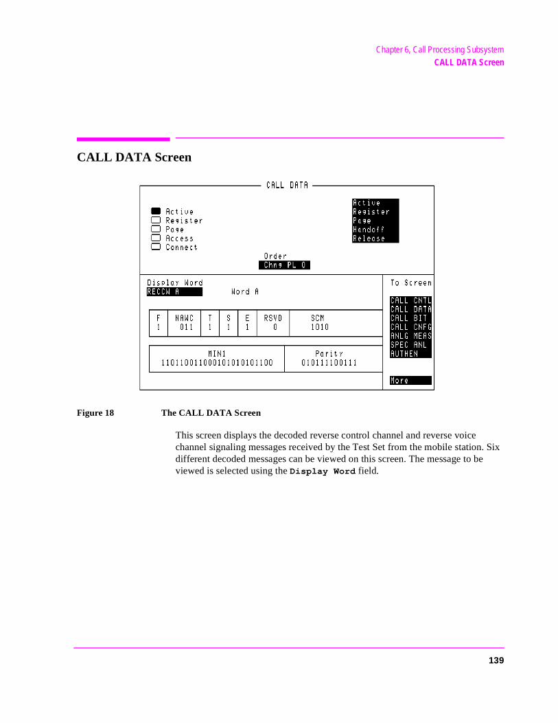
Chapter 6, Call Processing SubsystemCALL DATA Screen
CALL DATA Screen
Figure 18 The CALL DATA Screen
This screen displays the decoded reverse control channel and reverse voice channel signaling messages received by the Test Set from the mobile station. Six different decoded messages can be viewed on this screen. The message to be viewed is selected using the Display Word field.
139
Chapter 6, Call Processing SubsystemCALL DATA Screen
onfir-
e.
ing the power
The messages which can be viewed are:
• Reverse Control Channel Messages for Paging, Origination, Orders, and Order Cmation.
RECCW A - Word A - Abbreviated Address Word
RECCW B - Word B - Extended Address Word
RECCW C - Word C - Serial Number Word
RECCW D - Word D - First Word of the Called-Address
RECCW E - Word E - Second Word of the Called-Address
• Reverse Voice Channel Messages for Order Confirmation.
RVCOrdCon - Reverse Voice Channel Order Confirmation Message
The field descriptions for each of the decoded messages are given in the "CALL DATA Screen Message Field Descriptions" on page 144.
When the CALL DATA screen is displayed and the Call Processing Subsystem is in the connected state, the Test Set constantly monitors the mobile station’s transmitted carrier power. If the power falls below 0.0005Watts, the error message RF Power Loss indicates loss of Voice Channel will be displayed and the Test Set will terminate the call and return to the active stat
NOTE: In order to ensure that the Test Set makes the correct decisions regarding the presence of themobile stations’s RF carrier, the Test Set’s RF power meter should be zeroed before usCall Processing Subsystem. Failure to zero the power meter can result in erroneous RFmeasurements. See "Conditioning the Test Set for Call Processing" on page 130 forinformation on zeroing the RF Power meter manually.
140
Chapter 6, Call Processing SubsystemCALL DATA Screen
s
orce ect). If ld
t m ciator
is not
[] Access
When lit, the Access annunciator indicates the Test Set is signaling the mobile station with command information on the forward voice channel. This is a transitory state.
The Test Set’s speaker is turned off when in the access state. This is done toeliminate any possible audio feedback which may occur if the mobile station’microphone is open.
Active
This field is used to turn on the forward control channel of the Test Set or to fa return to the active state from any other state (register, page, access, connthe forward control channel of the Test Set is already active, selecting this fiewill deactivate and then reactivate the control channel.
[] Active
When lit, the Active annunciator indicates that the control channel of the TesSet is turned on. If this annunciator is lit, the base station is transmitting systeparameter overhead messages on the assigned control channel. If the annunis not lit the base station is not active.
NOTE: The Test Set may still be outputting a modulated RF carrier but the Test Set’s firmwareactive and no communication can occur between a mobile station and the Test Set.
[] Connect
When lit, the Connect annunciator indicates the mobile station is connected to the Test Set on a voice channel.
141
Chapter 6, Call Processing SubsystemCALL DATA Screen
Display Word
This field is used to select the desired reverse control channel or reverse voice channel message to be viewed.
Handoff
Order
This field is used to send an order on the forward voice channel to the mobile station. The orders available are:
• Change Power to Power Level 0 - 7
Maintenance (puts the mobile station in maintenance mode)
• Alert (alerts the mobile station)
The Order field is a one-of-many selection field. To send an order to the mobile station select the Order field. A list of choices is displayed. Select the desired order from the Choices: menu. Once the selection is made, a mobile station control message is sent to the mobile station. The Access annunciator will light momentarily while the Test Set is sending the mobile station control message.
NOTE: A mobile station must be actively connected on a voice channel to the Test Set (thatis, the Connect annunciator must be lit) before you can attempt to send an order to amobile station.
Page
This field is used to initiate a page to the mobile station connected to the Test Set. The Test Set must be in the active state (that is, the Active annunciator must be lit) and the MS Id information field on the CALL CONTROL screen must be correct before you can attempt to page a mobile station.
[] Page
When lit, the Page annunciator indicates that the mobile station connected to the Test Set is currently being paged on the forward control channel.
142
Chapter 6, Call Processing SubsystemCALL DATA Screen
Register
This field is used to initiate a registration of the mobile station connected to the Test Set. The Test Set must be in the active state (that is, the Active annunciator lit) before you can attempt to register a mobile station.
[] Register
When lit, the Register annunciator indicates that the mobile station connected to the Test Set is being commanded to register with the base station.
Release
This field is used to terminate an active voice channel connection to the mobile station. When the Release field is selected, a mobile station control message with a release order is sent to the mobile station on the forward voice channel. A mobile station must be actively connected on a voice channel to the Test Set (that is, the Connect annunciator must be lit) before you can attempt to send a release order to the mobile station.
143
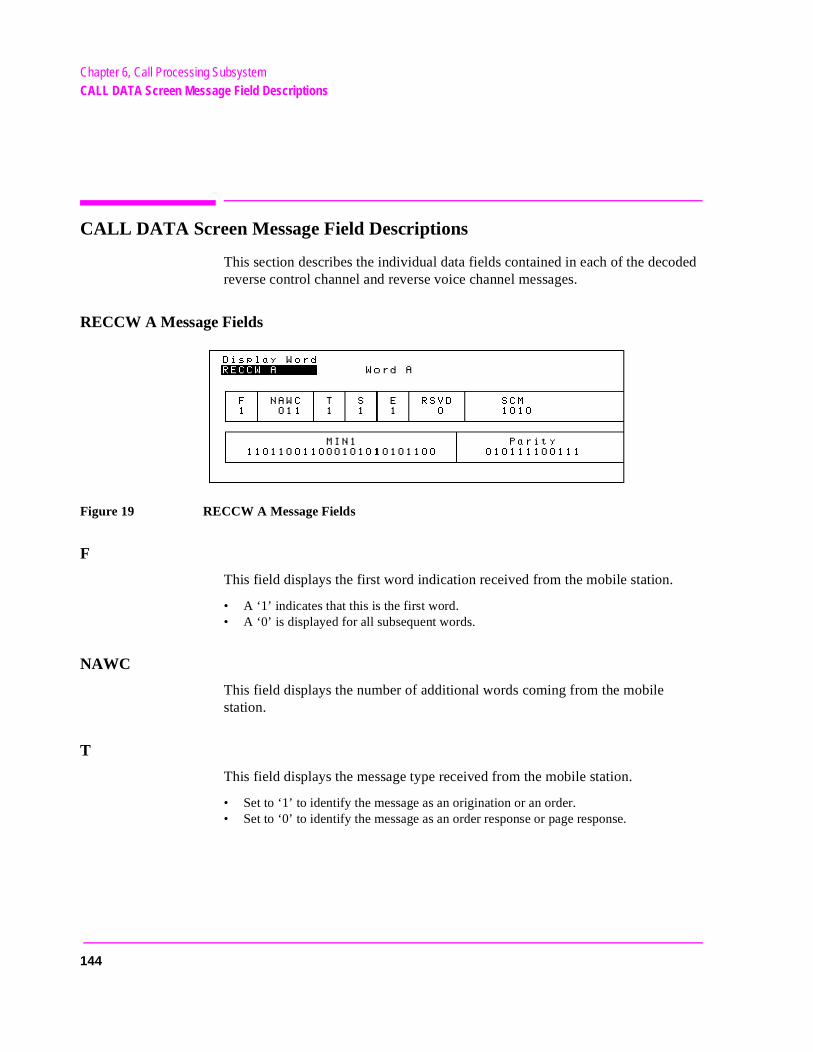
Chapter 6, Call Processing SubsystemCALL DATA Screen Message Field Descriptions
CALL DATA Screen Message Field Descriptions
This section describes the individual data fields contained in each of the decoded reverse control channel and reverse voice channel messages.
RECCW A Message Fields
Figure 19 RECCW A Message Fields
F
This field displays the first word indication received from the mobile station.
• A ‘1’ indicates that this is the first word. • A ‘0’ is displayed for all subsequent words.
NAWC
This field displays the number of additional words coming from the mobile station.
T
This field displays the message type received from the mobile station.
• Set to ‘1’ to identify the message as an origination or an order. • Set to ‘0’ to identify the message as an order response or page response.
144
Chapter 6, Call Processing SubsystemCALL DATA Screen Message Field Descriptions
om
S
This field displays whether the serial number word is received from the mobile station.
• Set to ‘1’ if the serial number word is sent. • Set to ‘0’ if the serial number word is not sent.
E
This field displays the extended address word received from the mobile.
• Set to ‘1’ if the extended address word is sent. • Set to ‘0’ if the extended address word is not sent.
RSVD
This field is reserved for future use.
SCM
This field displays the mobile station’s received station class mark.
MIN1
This field displays the first part of the mobile identification number received frthe mobile station.
Parity
This field displays the parity of the transmitted data.
145
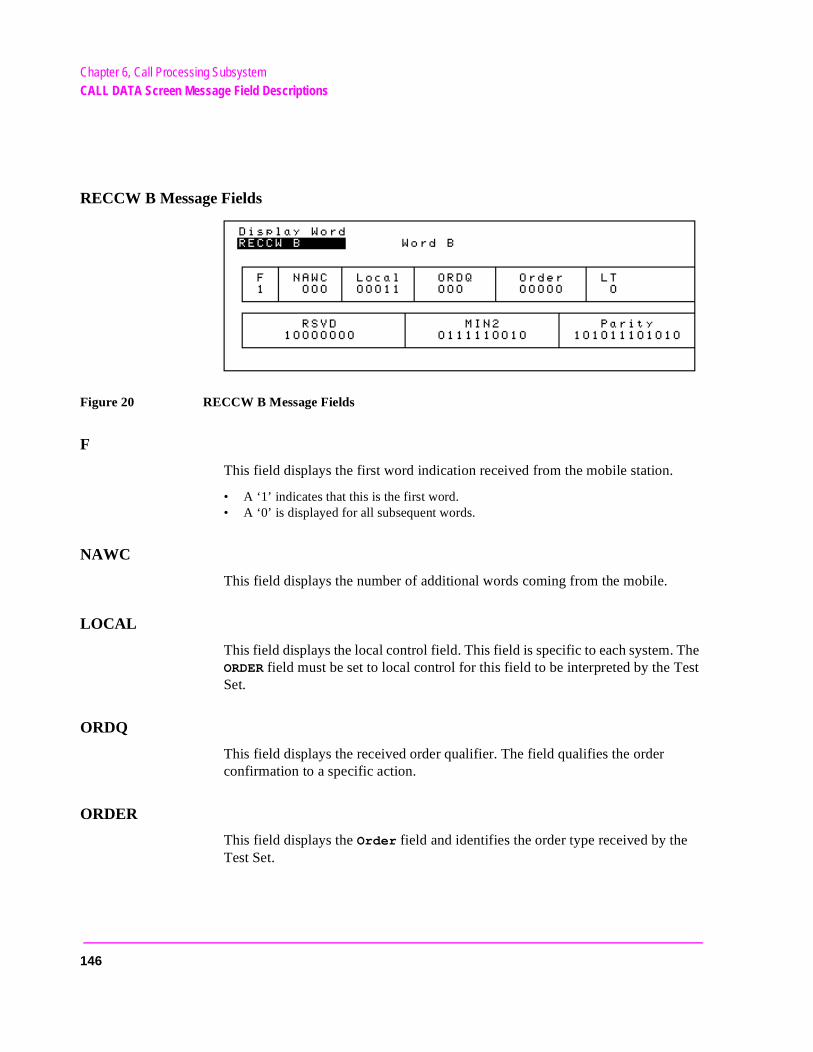
Chapter 6, Call Processing SubsystemCALL DATA Screen Message Field Descriptions
RECCW B Message Fields
Figure 20 RECCW B Message Fields
F
This field displays the first word indication received from the mobile station.
• A ‘1’ indicates that this is the first word. • A ‘0’ is displayed for all subsequent words.
NAWC
This field displays the number of additional words coming from the mobile.
LOCAL
This field displays the local control field. This field is specific to each system. The ORDER field must be set to local control for this field to be interpreted by the Test Set.
ORDQ
This field displays the received order qualifier. The field qualifies the order confirmation to a specific action.
ORDER
This field displays the Order field and identifies the order type received by the Test Set.
146
Chapter 6, Call Processing SubsystemCALL DATA Screen Message Field Descriptions
LT
This field displays the last-try code field.
RSVD
Reserved for future use.
MIN2
This field displays the second part of the mobile identification number received by the Test Set.
Parity
This field displays the parity of the received data.
147
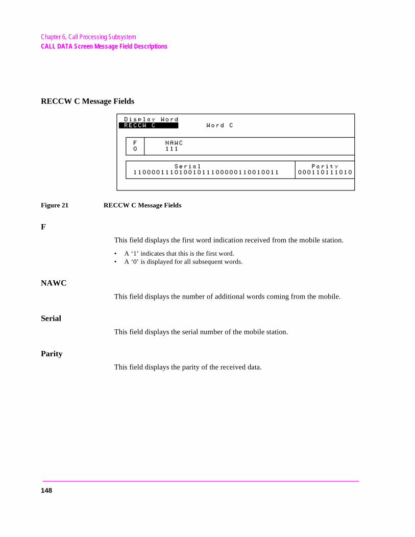
Chapter 6, Call Processing SubsystemCALL DATA Screen Message Field Descriptions
RECCW C Message Fields
Figure 21 RECCW C Message Fields
F
This field displays the first word indication received from the mobile station.
• A ‘1’ indicates that this is the first word. • A ‘0’ is displayed for all subsequent words.
NAWC
This field displays the number of additional words coming from the mobile.
Serial
This field displays the serial number of the mobile station.
Parity
This field displays the parity of the received data.
148
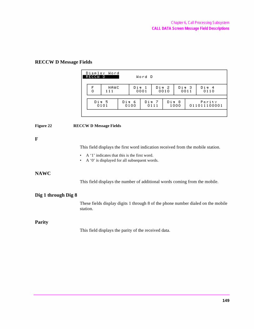
Chapter 6, Call Processing SubsystemCALL DATA Screen Message Field Descriptions
RECCW D Message Fields
Figure 22 RECCW D Message Fields
F
This field displays the first word indication received from the mobile station.
• A ‘1’ indicates that this is the first word. • A ‘0’ is displayed for all subsequent words.
NAWC
This field displays the number of additional words coming from the mobile.
Dig 1 through Dig 8
These fields display digits 1 through 8 of the phone number dialed on the mobile station.
Parity
This field displays the parity of the received data.
149
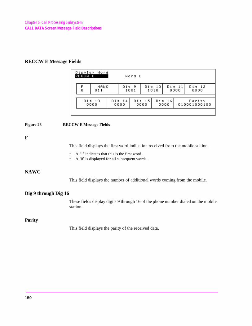
Chapter 6, Call Processing SubsystemCALL DATA Screen Message Field Descriptions
RECCW E Message Fields
Figure 23 RECCW E Message Fields
F
This field displays the first word indication received from the mobile station.
• A ‘1’ indicates that this is the first word. • A ‘0’ is displayed for all subsequent words.
NAWC
This field displays the number of additional words coming from the mobile.
Dig 9 through Dig 16
These fields display digits 9 through 16 of the phone number dialed on the mobile station.
Parity
This field displays the parity of the received data.
150
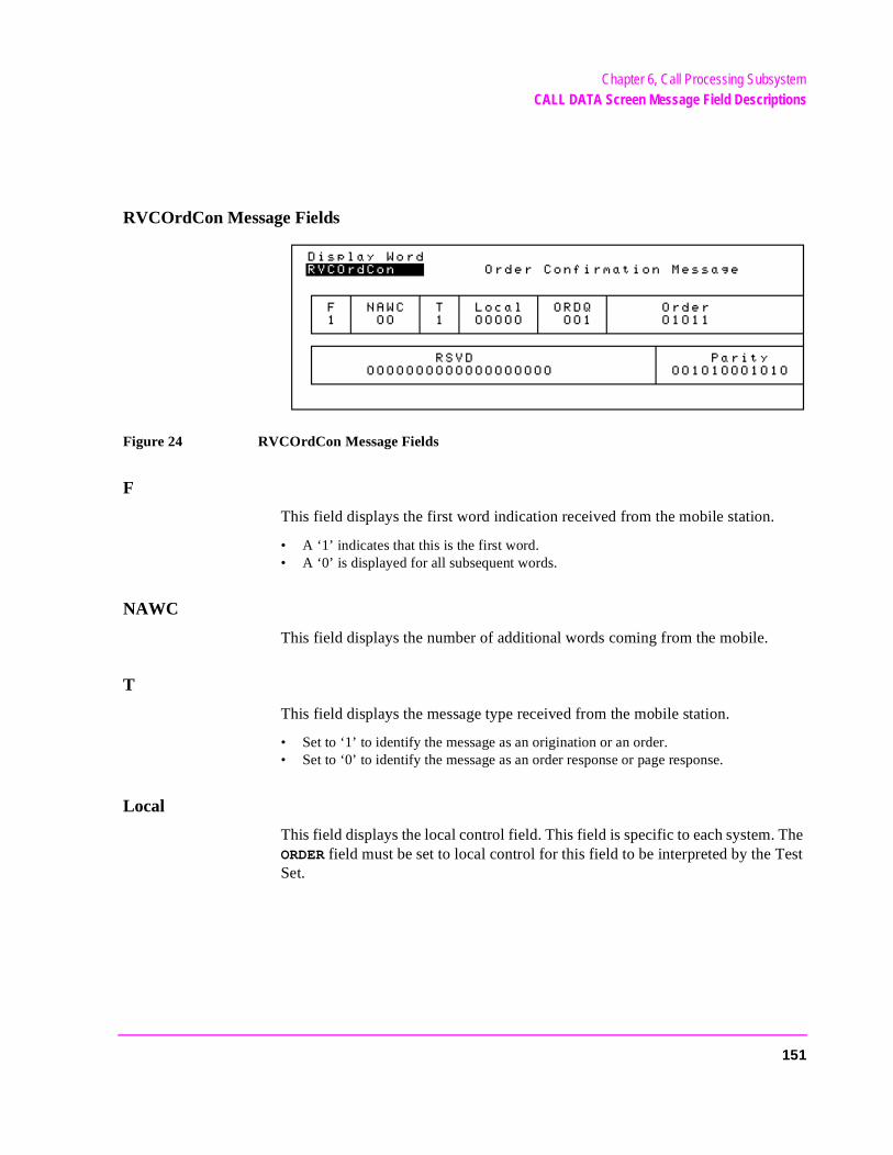
Chapter 6, Call Processing SubsystemCALL DATA Screen Message Field Descriptions
RVCOrdCon Message Fields
Figure 24 RVCOrdCon Message Fields
F
This field displays the first word indication received from the mobile station.
• A ‘1’ indicates that this is the first word. • A ‘0’ is displayed for all subsequent words.
NAWC
This field displays the number of additional words coming from the mobile.
T
This field displays the message type received from the mobile station.
• Set to ‘1’ to identify the message as an origination or an order. • Set to ‘0’ to identify the message as an order response or page response.
Local
This field displays the local control field. This field is specific to each system. The ORDER field must be set to local control for this field to be interpreted by the Test Set.
151
Chapter 6, Call Processing SubsystemCALL DATA Screen Message Field Descriptions
ORDQ
This field displays the received order qualifier. The field qualifies the order confirmation to a specific action.
Order
This field displays the Order field and identifies the order type received by the Test Set.
RSVD
Reserved for future use.
Parity
This field displays the parity of the received data.
152
Chapter 6, Call Processing SubsystemUsing the CALL DATA Screen
g is
Using the CALL DATA Screen
To View the Decoded Reverse Channel Words from a Mobile Station Registration1. If not already done, condition the Test Set. See "Conditioning the Test Set for Call
Processing" on page 130 for further information.2. If not already done, ensure that the Test Set is properly configured. See "Configure the
Test Set" on page 131 for further information.3. Connect the mobile station to the Test Set as shown in Figure 14, "Connecting a Mo-
bile Station to the Test Set," on page 115.4. Turn on the mobile station.5. If the CALL DATA screen is not displayed, select CALL DATA from the To Screen
menu. The CALL DATA screen will be displayed.6. Select the Active field. The Active annunciator will light when the control channel
is turned on.7. Select the Register field. The Register annunciator will light while the registra-
tion is in process. If the mobile station responds properly on the reverse control channel, the message RECC Return will flash momentarily in the upper right-hand corner of the CALL CONTROL screen. The Active annunciator will light when the registra-tion has successfully completed.
8. Select the Display Word field. A list of reverse channel words which can be dis-played will appear in a Choices: menu. Select the desired word from the list of choices. The decoded contents for each of the fields in the selected word will be dis-played in the lower portion of the display.
9. If a word is chosen which was not part of the decoded reverse channel message stream, all the fields will be blank when it is displayed.
10. See "CALL DATA Screen Message Field Descriptions" on page 144 for a descrip-tion of each of the available reverse channel words.
Step 7. and Step 8. in the above procedure can be reversed, that is, the desired word can be selected first, then the mobile station can be registered. If the registration is successful, the contents of each display word contained in the reverse control channel’s message stream will be updated when the decodincomplete.
The registration does not have to happen while you are viewing the CALL DATA screen. When the CALL DATA screen is viewed, the contents of the display words will be the decoded data from the last successful call processing function (registration, origination, page, release, order).
153
Chapter 6, Call Processing SubsystemUsing the CALL DATA Screen
ed
tered
l
the
ed
obile
ts for dis-
am, all
To View the Decoded Reverse Channel Words from a Mobile Station Page
There are two methods that can be used to view the decoded RVCC words from a mobile station page:
• View the decoded RVCC words from a page for a mobile station that has registerwith the Test Set
• View the decoded RVCC words from a page for a mobile station that has not regiswith the Test Set
Viewing the Decoded Reverse Channel Words from a Page to a Mobile Station that has Registered with the Test Set1. If not already done, condition the Test Set. See "Conditioning the Test Set for Call
Processing" on page 130 for further information.2. If not already done, ensure that the Test Set is properly configured. See "Configure the
Test Set" on page 131 for further information.3. Connect the mobile station to the Test Set as shown in Figure 14, "Connecting a Mo-
bile Station to the Test Set," on page 115.4. Turn on the mobile station.5. If the CALL DATA screen is not displayed, select CALL DATA under the To Screen
menu. The CALL DATA screen will be displayed.6. Select the Active field. The Active annunciator will light when the control channe
is turned on.7. Ensure that the mobile station has registered with the Test Set. See "Register a Mobile
Station" on page 132 for information on how to register the mobile station.8. Select the Page field. The Page annunciator will light while the Test Set pages the
mobile on the forward control channel. If the mobile station responds properly onreverse control channel, the message RECC Return will flash momentarily in the up-per right-hand corner of the CALL CONTROL screen. The Access annunciator will then light while the Test Set sends the mobile station an alert order on the assignvoice channel. The mobile station should ring.
9. Press the SEND key on the mobile station. The Connect annunciator will light if the mobile station properly signals the Test Set when the SEND key is pressed. The mstation is now connected to the Test Set on the assigned voice channel.
10. Select the Display Word field. A list of reverse channel words appears in a Choic-es: menu. Select the desired word from the list of choices. The decoded conteneach of the fields in the selected word will be displayed in the lower portion of theplay.
NOTE: If a word is chosen which was not part of the decoded reverse channel’s message strethe fields will be blank when it is displayed.
See "CALL DATA Screen Message Field Descriptions" on page 144 for a descrip-tion of each of the available reverse channel words.
154
Chapter 6, Call Processing SubsystemUsing the CALL DATA Screen
ion
Step 8. and Step 10. in the above procedure can be reversed, that is, the desired word can be selected first, then the mobile station can be paged. If the page is successful, the contents of each display word contained in the reverse control channel’s message stream will be updated when the decoding is complete.
The page does not have to happen while you are viewing the CALL DATA screen. When the CALL DATA screen is viewed, the contents of the display words will be the decoded data from the last successful call processing funct(registration, origination, page, release, order).
Viewing the Decoded Reverse Channel Words from a Page to a Mobile Station That Has Not Registered with the Test Set1. If not already done, condition the Test Set. See "Conditioning the Test Set for Call
Processing" on page 130 for further information.2. If not already done, configure the Test Set See "Configure the Test Set" on page 131
for further information.3. Connect the mobile station to the Test Set as shown in Figure 14, "Connecting a Mo-
bile Station to the Test Set," on page 115.4. Turn on the mobile station.5. If the CALL CONTROL screen is not displayed, select CALL CNTL under the To
Screen menu. The CALL CONTROL screen will be displayed.6. Select the lower MS Id field. Enter the mobile station identification number, either the
phone number or the MIN number depending upon what the upper MS Id field is set to.7. Select CALL DATA from the To Screen menu. The CALL DATA screen will be
displayed.8. Select the Active field. The Active annunciator will light when the control channel
is turned on.9. Select the Page field. The Page annunciator will light while the Test Set pages the
mobile on the forward control channel. If the mobile station responds properly on the reverse control channel, the message RECC Return will flash momentarily in the up-per right-hand corner of the CALL CONTROL screen. The Access annunciator will then light while the Test Set sends the mobile station an alert order on the assigned voice channel. The mobile station should ring.
10. Press the SEND key on the mobile station. The Connect annunciator will light if the mobile station properly signals the Test Set when the SEND key is pressed. The mobile station is now connected to the Test Set on the assigned voice channel.
11. Select the Display Word field. A list of reverse channel words which can be dis-played will appear in a Choices: menu. Select the desired word from the list of choices. The decoded contents for each of the fields in the selected word will be dis-played in the lower portion of the display.
155
Chapter 6, Call Processing SubsystemUsing the CALL DATA Screen
am, all
ion
NOTE: If a word is chosen which was not part of the decoded reverse channel’s message strethe fields will be blank when it is displayed.
See "CALL DATA Screen Message Field Descriptions" on page 144 for a descrip-tion of each of the available reverse channel words.
Step 9. and step 11. in the above procedure can be reversed, that is - the desired word can be selected first, then the mobile station can be paged. If the page is successful, the contents of each display word contained in the reverse control channel’s message stream will be updated when the decoding is complete.
The page does not have to happen while you are viewing the CALL DATA screen. When the CALL DATA screen is viewed, the contents of the display words will be the decoded data from the last successful call processing funct(registration, origination, page, release, order).
To View the Decoded Reverse Channel Words From a Mobile Station Handoff1. If not already done, condition the Test Set. See "Conditioning the Test Set for Call
Processing" on page 130 for further information.2. If not already done, configure the Test Set. See "Configure the Test Set" on page 131
for further information.3. Connect the mobile station to the Test Set as shown in Figure 14, "Connecting a Mo-
bile Station to the Test Set," on page 115.4. Turn on the mobile station.5. Ensure that the Test Set is in the Connect state. See "Page a Mobile Station" on
page 133 for information on how to bring a mobile station up on a voice channel.6. If the CALL CONTROL screen is not displayed, Select CALL CNTL from the To
Screen menu. The CALL CONTROL screen will be displayed.7. Select the Chan: field and enter a new, valid voice channel number from the choices
provided.8. Select the Pwr Lvl: field and enter a new, valid mobile station power level.9. Select the SAT: field and enter a new, valid SAT frequency.10. Select CALL DATA from the To Screen menu. The CALL DATA screen will be
displayed.11. Select the Handoff field. The Access annunciator will light while the Test Set sig-
nals the mobile station with the handoff information. If the mobile responds properly, it will stop transmitting on the current voice channel, switch to the new voice channel assignment, and transpond the new SAT frequency assignment. When the Test Set de-tects this has happened, the Connect annunciator lights indicating the handoff was successful.
156
Chapter 6, Call Processing SubsystemUsing the CALL DATA Screen
e
plete.
12. Select the Display Word field. A list of reverse channel words which can be dis-played will appear in a Choices: menu. Select the desired word from the list of choices. The decoded contents for each of the fields in the selected word will be dis-played in the lower portion of the display.
13. If a word is chosen which was not part of the decoded reverse channel’s messagstream, all the fields will be blank when it is displayed.
See "CALL DATA Screen Message Field Descriptions" on page 144 for a description of each of the available reverse channel words.
Step 11. and step 12. in the above procedure can be reversed, that is - the desired word can be selected first, then the mobile station can be handed off. If the handoff is successful, the contents of each display word contained in the reverse control channel’s message stream will be updated when the decoding is com
The handoff does not have to happen while you are viewing the CALL DATAscreen. When the CALL DATA screen is viewed, the contents of the display words will contain the decoded data from the last successful call processing function (registration, origination, page, release, order).
157
Chapter 6, Call Processing SubsystemUsing the CALL DATA Screen
e
To View the Decoded Reverse Channel Words from a Mobile Station Release1. If not already done, condition the Test Set. See "Conditioning the Test Set for Call
Processing" on page 130 for further information.2. If not already done, configure the Test Set. See "Configure the Test Set" on page 131
for further information.3. Connect the mobile station to the Test Set as shown in Figure 14, "Connecting a Mo-
bile Station to the Test Set," on page 115.4. Turn on the mobile station.5. Ensure that the Test Set is in the Connect state. See "Page a Mobile Station" on
page 133 for information on how to bring a mobile station up on a voice channel.6. Select CALL DATA under the To Screen menu. The CALL DATA screen will be
displayed.7. Select the Release field. The Test Set will signal the mobile station with a release or-
der. The mobile station will respond to the release order and cease transmission. The Test Set will terminate transmission on the forward voice channel and the Connect annunciator will turn off. The Test Set will then reconfigure itself for transmission on the forward control channel, begin to transmit system parameter overhead messages and the Active annunciator will light.
8. Select the Display Word field. A list of reverse channel words which can be dis-played will appear in a Choices: menu. Select the desired word from the list of choices. The decoded contents for each of the fields in the selected word will be displayed in the lower portion of the display.
9. If a word is chosen which was not part of the decoded reverse channel’s messagstream, all the fields will be blank when it is displayed.
10. See "CALL DATA Screen Message Field Descriptions" on page 144 for a descrip-tion of each of the available reverse channel words.
Step 7. and step 8. in the above procedure can be reversed, that is, the desired word can be selected first, then the mobile station can be released. If the release is successful, the contents of each display word contained in the reverse control channel’s message stream will be updated when the decoding is complete.
The release does not have to happen while you are viewing the CALL DATAscreen. When the CALL DATA screen is viewed, the contents of the display words will contain the decoded data from the last successful call processing function (registration, origination, page, release, order).
158
Chapter 6, Call Processing SubsystemUsing the CALL DATA Screen
e
hen
e d, ssful
To View the Decoded Reverse Channel Words from an Order to Change the Transmit Power Level of a Mobile Station
1. If not already done, condition the Test Set. See "Conditioning the Test Set for Call Processing" on page 130 for further information.
2. If not already done, configure the Test Set. See "Configure the Test Set" on page 131 for further information.
3. Connect the mobile station to the Test Set as shown in Figure 14, "Connecting a Mo-bile Station to the Test Set," on page 115.
4. Turn on the mobile station.5. Ensure that the Test Set is in the Connect state. See "Page a Mobile Station" on
page 133 for information on how to bring a mobile station up on a voice channel.6. If the CALL DATA screen is not displayed, select CALL DATA under the To Screen
menu. The CALL DATA screen will be displayed.7. Select the Order field and select it. A Choices: menu is displayed showing the var-
ious power levels which the mobile station can be set to. Select the desired power level. The Access annunciator will light while the Test Set signals the mobile station with an order to set its power level. If the mobile responds properly, the message REVC Re-turn will flash momentarily in the upper right-hand corner of the CALL CONTROL screen. The Connect annunciator will light when signaling is complete.
8. Select the Display Word field. A list of reverse channel words which can be dis-played will be presented. Position the cursor on the desired word and select it. The de-coded contents for each of the fields in the selected word will be displayed in the lower portion of the display.
9. If a word is chosen which was not part of the decoded reverse channel’s messagstream, all the fields will be blank when it is displayed.
10. See "CALL DATA Screen Message Field Descriptions" on page 144 for a descrip-tion of each of the available reverse channel words.
Step 7. and Step 8. in the above procedure can be reversed, that is, the desired word can be selected first, then the mobile station can be sent an order to change transmit power level. If the order is successful, the contents of each display word contained in the reverse control channel’s message stream will be updated wthe decoding is complete.
The ordered to change transmit power does not have to happen while you arviewing the CALL CONTROL screen. When the CALL DATA screen is viewethe contents of the display words will be the decoded data from the last succecall processing function (registration, origination, page, release, order).
159
Chapter 6, Call Processing SubsystemUsing the CALL DATA Screen
ontrol e mo-mit-
est
ned -ted to
e de-wer
am, all
g is
TA
To View The Reverse Channel Words From a Mobile Station Origination1. If not already done, condition the Test Set. See "Conditioning the Test Set for Call
Processing" on page 130 for further information.2. If not already done, configure the Test Set. See "Configure the Test Set" on page 131
for further information.3. Connect the mobile station to the Test Set as shown in Figure 14, "Connecting a Mo-
bile Station to the Test Set," on page 115.4. Turn on the mobile station.5. Ensure that the Test Set is in the Connect state. See "Page a Mobile Station" on
page 133 for information on how to bring a mobile station up on a voice channel.6. Select the Active field. The Active annunciator will light when the control channel
is turned on.7. Dial the desired phone number on the mobile station and press the SEND key on the
mobile station’s handset. The mobile station signals the Test Set on the reverse cchannel with an origination message which includes the dialed phone number, thbile station’s MIN number and the mobile station’s ESN. If the mobile station transted properly on the reverse control channel, the message RECC Return will flash momentarily in the upper right-hand corner of the CALL CONTROL screen. The TSet will then reconfigure itself to the voice channel assignments set up in the Voice Channel Assignment section of the CALL CONTROL screen. The Access an-nunciator will then light while the Test Set signals the mobile station on the assigvoice channel. The Connect annunciator will light if the mobile station properly signals the Test Set on the reverse voice channel. The mobile station is now connecthe Test Set on the assigned voice channel.
8. Select the Display Word field. A list of reverse channel words which can be dis-played will be presented. Position the cursor on the desired word and select it. Thcoded contents for each of the fields in the selected word will be displayed in the loportion of the display.
NOTE: If a word is chosen which was not part of the decoded reverse channel’s message strethe fields will be blank when it is displayed.
See "CALL DATA Screen Message Field Descriptions" on page 144 for a descrip-tion of each of the available reverse channel words.
Step 7. and Step 8. in the above procedure can be reversed, that is, the desired word can be selected first, then a mobile station origination can performed. If the origination is successful, the contents of each display word contained in the reverse control channel’s message stream will be updated when the decodincomplete.
The origination does not have to happen while you are viewing the CALL DAscreen.When the CALL DATA screen is viewed, the contents of the display words will contain the decoded data from the last successful call processing function (registration, origination, page, release, order).
160
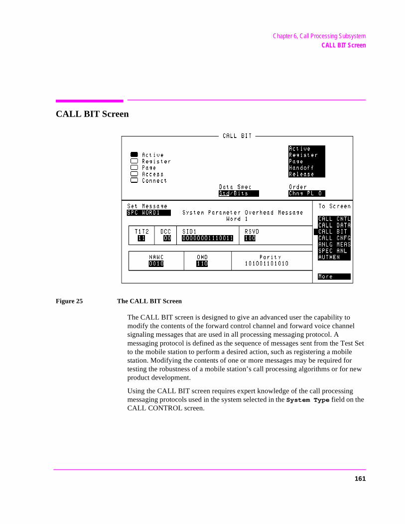
Chapter 6, Call Processing SubsystemCALL BIT Screen
ew
CALL BIT Screen
Figure 25 The CALL BIT Screen
The CALL BIT screen is designed to give an advanced user the capability to modify the contents of the forward control channel and forward voice channel signaling messages that are used in all processing messaging protocol. A messaging protocol is defined as the sequence of messages sent from the Test Set to the mobile station to perform a desired action, such as registering a mobile station. Modifying the contents of one or more messages may be required for testing the robustness of a mobile station’s call processing algorithms or for nproduct development.
Using the CALL BIT screen requires expert knowledge of the call processingmessaging protocols used in the system selected in the System Type field on the CALL CONTROL screen.
161
Chapter 6, Call Processing SubsystemCALL BIT Screen
d
ing the power
The CALL BIT screen should not be used to change any parameter that can be set on any other Call Processing Subsystem screen. The contents of the applicable fields on the CALL CONTROL screen and the CALL CONFIGURE screen are not updated to reflect any changes made while using the CALL BIT screen. There is no coupling between the CALL BIT screen and the Test Set.
For example: changing the value of the SAT color code field (SCC) in the forward control channel mobile station control message (MS IntVCh) does not change the setting of the SAT: field on the CALL CONTROL screen.
When using the CALL BIT screen the user is responsible for setting the contents of all messages used in a messaging protocol. When using the CALL BIT screen, the Call Processing Subsystem sends the correct messages at the correct times as defined in the applicable industry standard. Message content is the responsibility of the user.
When the CALL BIT screen is displayed and the Call Processing Subsystem is in the connected state, the Test Set constantly monitors the station’s transmittecarrier power. If the Power falls below 0.0005 Watts, the error message RF Power Loss indicates loss of Voice Channel will be displayed and the Test Set will terminate the call and return to the active state.
NOTE: In order to ensure that the Test Set makes the correct decisions regarding the presence of themobile stations’s RF carrier, the Test Set’s RF power meter should be zeroed before usCall Processing Subsystem. Failure to zero the power meter can result in erroneous RFmeasurements. See "Conditioning the Test Set for Call Processing" on page 130 forinformation on manually zeroing the RF Power meter.
The field descriptions for each of the messages are given in the "CALL BIT Screen Message Field Descriptions" on page 167.
162
Chapter 6, Call Processing SubsystemCALL BIT Screen
and
ss
s-
s
e
s
orce ect). If ld
Message Contents that can be Modified Using the CALL BIT screen
The contents of eleven different messages can be modified from this screen. The message to be modified is selected using the Set Message field. The eleven messages whose contents can be modified are:
• Forward Control Channel Messages for Paging, Origination, Order Confirmation, Orders.
• SPC WORD1 - System Parameter Overhead Message Word 1• SPC WORD2 - System Parameter Overhead Message Word 2• ACCESS - Access Type Parameters Global Action Message• REG INC - Registration Increment Global Action Message• REG ID - Registration ID Message• C-FILMESS - Control-Filler Message• MS WORD1 - FCC mobile station control message Word 1- Abbreviated Addre
Word• MS IntVCh - FCC mobile station control message Word 2- Extended Addres
Word - Voice Channel Assignment• MSMessOrd - FCC mobile station control message Word 2- Extended Addres
Word - Order• FVC V Mes - FVC Mobile Station Control Voice Channel Assignment Messag• FVC O Mes - FVC Mobile Station Control Order Message
[] Access
When lit, the Access annunciator indicates that the Test Set is signaling the mobile station with command information on the forward voice channel. This is a transitory state.
The Test Set’s speaker is turned off when in the access state. This is done toeliminate any possible audio feedback which may occur if the mobile station’microphone is open.
Active
This field is used to turn on the forward control channel of the Test Set or to fa return to the active state from any other state (register, page, access, connthe forward control channel of the Test Set is already active, selecting this fiewill deactivate and then reactivate the control channel.
163
Chapter 6, Call Processing SubsystemCALL BIT Screen
ed
re
the
never the
trol
ering sing
ging
[] Active
When lit, the Active annunciator indicates that the control channel of the Test Set is turned on. If this annunciator is lit the base station is transmitting system parameter overhead messages on the assigned control channel. If the annunciator is not lit the base station is not active (note that the Test Set may still be outputting a modulated RF carrier but the Test Set’s firmware is not active and no communication can occur between a mobile station and the Test Set).
[] Connect
When lit, the Connect annunciator indicates that the mobile station is connectto the Test Set on a voice channel.
Data Spec
This field is used to determine how the contents of the signaling messages abuilt.
• Std -Use the signaling formats defined in the applicable industry standard to buildforward control channel and forward voice channel signaling messages. Use the contents of the applicable fields on the CALL CONTROL screen and the CALL CONFIGURE screen to obtain information necessary to build the messages. Whea signaling message is used, update the contents of all fields in that message onCALL BIT screen.
• Bits -Use the bit patterns as set on the CALL BIT screen to build all forward conchannel and forward voice channel signaling messages. For any call processing function (that is, setting the message stream on the active control channel, registthe mobile station, paging the mobile station, handing off the mobile station or releathe mobile station) the user is responsible for setting the contents of all signalingmessages used in that function. The Call Processing Subsystem uses the messaprotocol as defined in the applicable industry standard.
164
Chapter 6, Call Processing SubsystemCALL BIT Screen
NOTE: The contents of the applicable fields on the CALL CONTROL screen and the CALLCONFIGURE screen are not updated to reflect any changes made while in the Bits mode.There is no coupling between the Bits mode and the Test Set. For example: if a mobile stationwas actively connected to the Test Set on a voice channel and the user changed the CHAN fieldon the forward voice channel mobile station control message (FVC V Mes) and sent thatmessage to the mobile station, the mobile station would change its voice channel assignment.However, the Test Set will stay on the voice channel assignment specified in the Chan: fieldon the CALL CONTROL screen. This situation will result in a dropped call. The Bits modeshould not be used to change any parameter that can be set on any other Call ProcessingSubsystem screen.
Handoff
This field is used to initiate a handoff from the current voice channel assignments to a new set of voice channel assignments. The voice channel number to hand the mobile station off to, the initial power level to use on the new voice channel, and the SAT tone frequency to transpond on the new voice channel are specified using the Chan:, Pwr Lvl:, and SAT: fields in the Voice Channel Assignment section of the CALL CONTROL screen.
Order
This field is used to send an order type mobile station control message on the forward voice channel to the mobile station. The orders available are:
• Change Power to Power Level 0 - 7• Maintenance (put the mobile station in maintenance mode) • Alert (alert the mobile station)
The Order field is a one-of-many selection field. To send an order to the mobile station select the Order field. A list of choices is displayed. Select the desired order from the Choices: menu. Once the selection is made, a Mobile Station Control Message is sent to the mobile station. The Access annunciator will light momentarily while the Test Set is sending the mobile station control message.
165
Chapter 6, Call Processing SubsystemCALL BIT Screen
NOTE: A mobile station must be actively connected on a voice channel to the Test Set (thatis, the Connect annunciator lit) before you can attempt to send an order to a mobilestation.
Page
This field is used to initiate a page to the mobile station connected to the Test Set. The Test Set must be in the active state (that is, Active annunciator must be lit) and the MS Id information field on the CALL CONTROL screen must be correct before you can attempt to page a mobile station.
[] Page
When lit, the Page annunciator indicates that the mobile station connected to the Test Set is currently being paged on the forward control channel.
Register
This field is used to initiate a registration of the mobile station connected to the Test Set. The Test Set must be in the active state (that is, the Active annunciator must be lit) before you can attempt to register a mobile station.
[] Register
When lit, the Register annunciator indicates that the mobile station connected to the Test Set is being commanded to register with the base station.
Release
This field is used to terminate an active voice channel connection to the mobile station. When the Release field is selected, a mobile station control message with a release order is sent to the mobile station on the forward voice channel. A mobile station must be actively connected on a voice channel to the Test Set (that is, the Connect annunciator must be lit) before you can attempt to send a release order to the mobile station.
Set Message
This field is used to select the desired forward control channel or forward voice channel message to be modified.
166
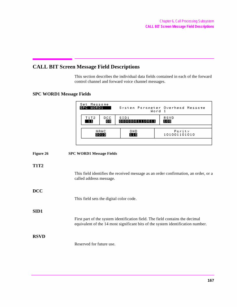
Chapter 6, Call Processing SubsystemCALL BIT Screen Message Field Descriptions
CALL BIT Screen Message Field Descriptions
This section describes the individual data fields contained in each of the forward control channel and forward voice channel messages.
SPC WORD1 Message Fields
Figure 26 SPC WORD1 Message Fields
T1T2
This field identifies the received message as an order confirmation, an order, or a called address message.
DCC
This field sets the digital color code.
SID1
First part of the system identification field. The field contains the decimal equivalent of the 14 most significant bits of the system identification number.
RSVD
Reserved for future use.
167
Chapter 6, Call Processing SubsystemCALL BIT Screen Message Field Descriptions
sage.age.
NAWC
This field displays the number of additional words coming.
OHD
This field displays the overhead message type.
• A ‘100’ indicates a global action message.• A ‘110’ indicates that this is the first word of the system overhead parameter mes• A ‘111’ indicates this is the second word of the system parameter overhead mess
Parity
Parity field. The contents of the Parity field cannot be set by the user. The Test Set calculates the parity bits.
168
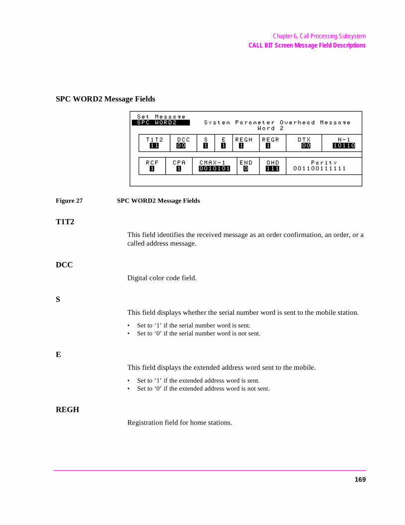
Chapter 6, Call Processing SubsystemCALL BIT Screen Message Field Descriptions
SPC WORD2 Message Fields
Figure 27 SPC WORD2 Message Fields
T1T2
This field identifies the received message as an order confirmation, an order, or a called address message.
DCC
Digital color code field.
S
This field displays whether the serial number word is sent to the mobile station.
• Set to ‘1’ if the serial number word is sent. • Set to ‘0’ if the serial number word is not sent.
E
This field displays the extended address word sent to the mobile.
• Set to ‘1’ if the extended address word is sent. • Set to ‘0’ if the extended address word is not sent.
REGH
Registration field for home stations.
169
Chapter 6, Call Processing SubsystemCALL BIT Screen Message Field Descriptions
sage.age.
REGR
Registration field for roaming stations.
DTX
Discontinuous transmission field.
N-1
N is the number of paging channels in the system.
RCF
Read-control-filler field.
CPA
Combined paging/access field.
CMAX-1
CMAX is the number of access channels in the system.
END
End indication field.
• Set to 1 to indicate the last word of the overhead message train.• Set to 0 if not the last word.
OHD
This field displays the overhead message type.
• A ‘100’ indicates a global action message.• A ‘110’ indicates that this is the first word of the system overhead parameter mes• A ‘111’ indicates this is the second word of the system parameter overhead mess
Parity
Parity field. The contents of the Parity field cannot be set by the user. The Test Set calculates the parity bits.
170
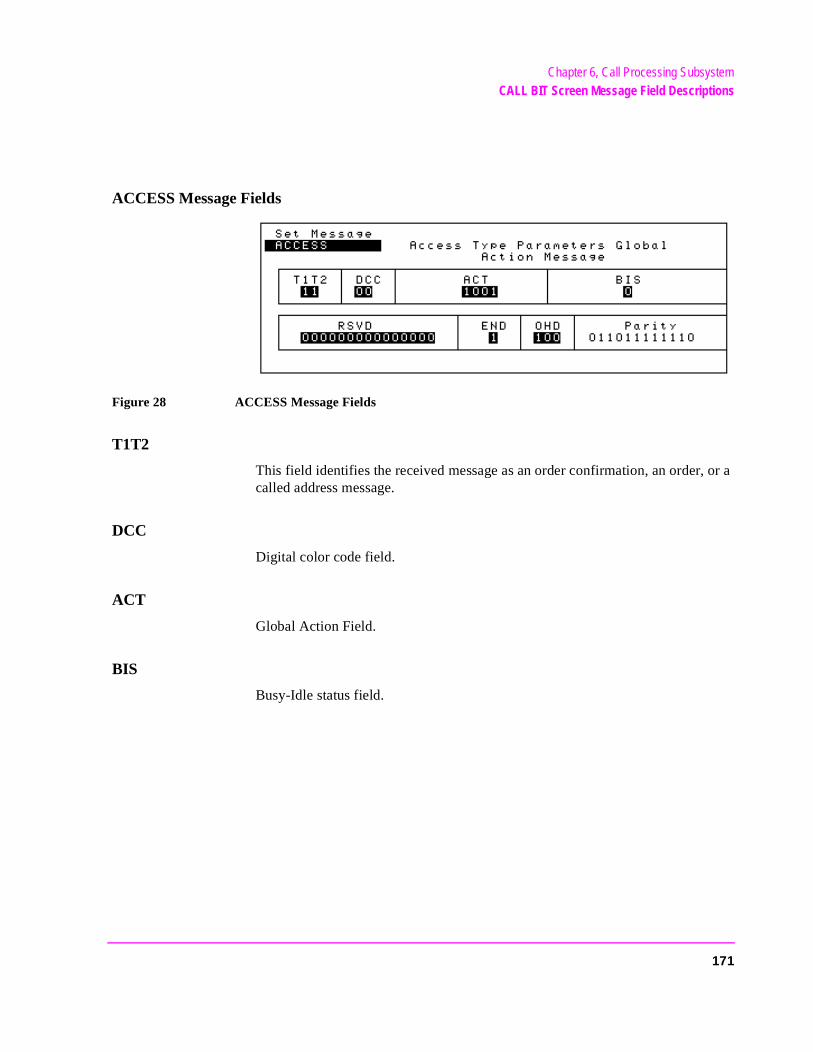
Chapter 6, Call Processing SubsystemCALL BIT Screen Message Field Descriptions
ACCESS Message Fields
Figure 28 ACCESS Message Fields
T1T2
This field identifies the received message as an order confirmation, an order, or a called address message.
DCC
Digital color code field.
ACT
Global Action Field.
BIS
Busy-Idle status field.
171
Chapter 6, Call Processing SubsystemCALL BIT Screen Message Field Descriptions
er
age.
RSVD
Reserved for future use, all bits must be set as indicated.
END
End indication field.
• Set to 1 to indicate the last word of the overhead message train.• Set to 0 if not the last word.
OHD
This field displays the overhead message type.
• A ‘100’ indicates a global action message.• A ‘110’ indicates this is the first word of the system parameter overhead paramet
message.• A ‘111’ indicates this is the second word of the system parameter overhead mess
Parity
Parity field. The contents of the Parity field cannot be set by the user. The Test Set calculates the parity bits.
172
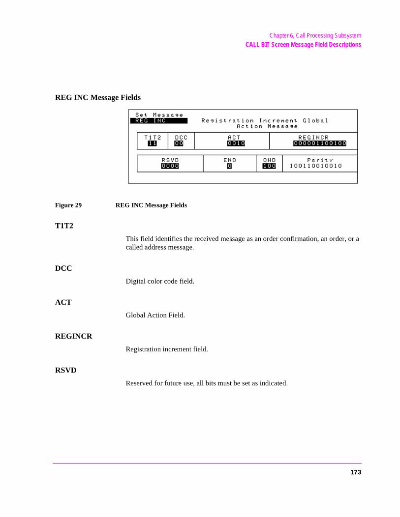
Chapter 6, Call Processing SubsystemCALL BIT Screen Message Field Descriptions
REG INC Message Fields
Figure 29 REG INC Message Fields
T1T2
This field identifies the received message as an order confirmation, an order, or a called address message.
DCC
Digital color code field.
ACT
Global Action Field.
REGINCR
Registration increment field.
RSVD
Reserved for future use, all bits must be set as indicated.
173
Chapter 6, Call Processing SubsystemCALL BIT Screen Message Field Descriptions
er
age.
END
End indication field.
• Set to 1 to indicate the last word of the overhead message train.• Set to 0 if not the last word.
OHD
This field displays the overhead message type.
• A ‘100’ indicates a global action message.• A ‘110’ indicates this is the first word of the system parameter overhead paramet
message.• A ‘111’ indicates this is the second word of the system parameter overhead mess
Parity
Parity field. The contents of the Parity field cannot be set by the user. The Test Set calculates the parity bits.
174
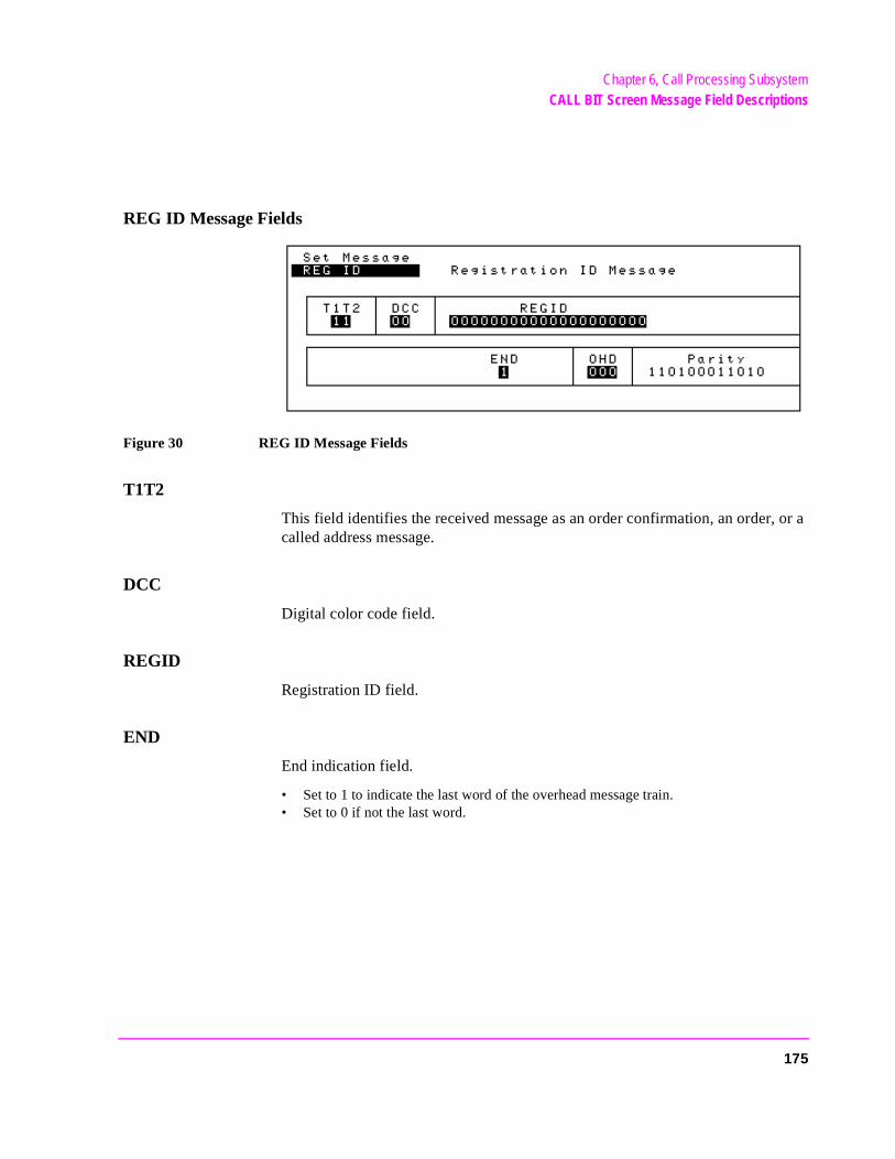
Chapter 6, Call Processing SubsystemCALL BIT Screen Message Field Descriptions
REG ID Message Fields
Figure 30 REG ID Message Fields
T1T2
This field identifies the received message as an order confirmation, an order, or a called address message.
DCC
Digital color code field.
REGID
Registration ID field.
END
End indication field.
• Set to 1 to indicate the last word of the overhead message train.• Set to 0 if not the last word.
175
Chapter 6, Call Processing SubsystemCALL BIT Screen Message Field Descriptions
er
age.
OHD
This field displays the overhead message type.
• A ‘100’ indicates a global action message.• A ‘110’ indicates this is the first word of the system parameter overhead paramet
message.• A ‘111’ indicates this is the second word of the system parameter overhead mess
Parity
Parity field. The contents of the Parity field cannot be set by the user. The Test Set calculates the parity bits.
176
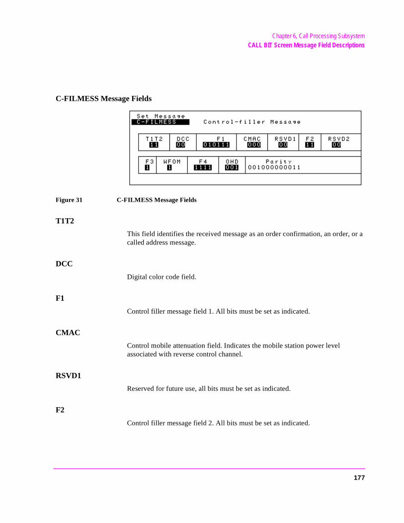
Chapter 6, Call Processing SubsystemCALL BIT Screen Message Field Descriptions
C-FILMESS Message Fields
Figure 31 C-FILMESS Message Fields
T1T2
This field identifies the received message as an order confirmation, an order, or a called address message.
DCC
Digital color code field.
F1
Control filler message field 1. All bits must be set as indicated.
CMAC
Control mobile attenuation field. Indicates the mobile station power level associated with reverse control channel.
RSVD1
Reserved for future use, all bits must be set as indicated.
F2
Control filler message field 2. All bits must be set as indicated.
177
Chapter 6, Call Processing SubsystemCALL BIT Screen Message Field Descriptions
er
age.
RSVD2
Reserved for future use, all bits must be set as indicated.
F3
Control filler message field 3. All bits must be set as indicated.
WFOM
Wait-for-overhead-message field.
F4
Control filler message field 4. All bits must be set as indicated.
OHD
This field displays the overhead message type.
• A ‘100’ indicates a global action message.• A ‘110’ indicates this is the first word of the system parameter overhead paramet
message.• A ‘111’ indicates this is the second word of the system parameter overhead mess
Parity
Parity field. The contents of the Parity field cannot be set by the user. The Test Set calculates the parity bits.
178
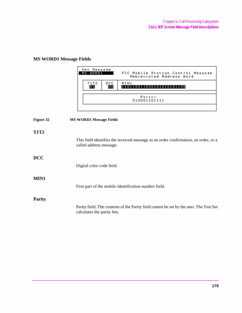
Chapter 6, Call Processing SubsystemCALL BIT Screen Message Field Descriptions
MS WORD1 Message Fields
Figure 32 MS WORD1 Message Fields
T1T2
This field identifies the received message as an order confirmation, an order, or a called address message.
DCC
Digital color code field.
MIN1
First part of the mobile identification number field.
Parity
Parity field. The contents of the Parity field cannot be set by the user. The Test Set calculates the parity bits.
179
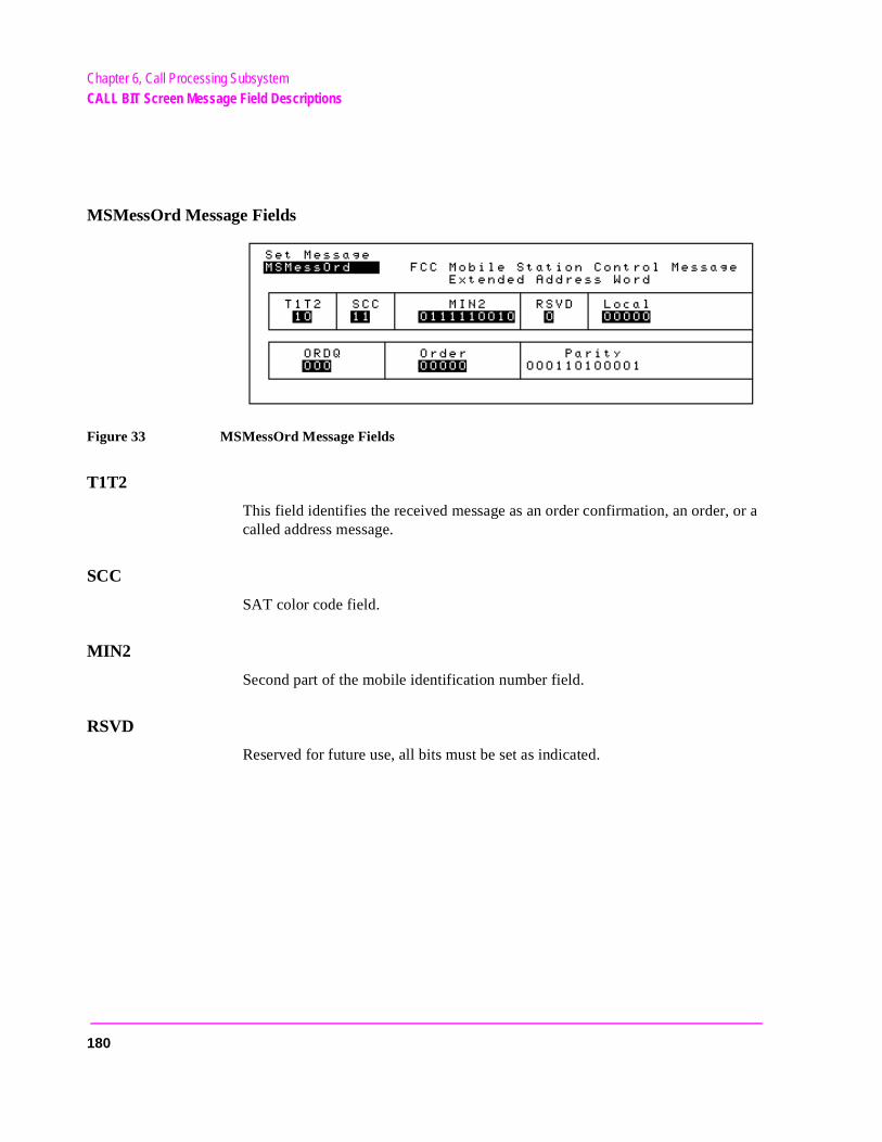
Chapter 6, Call Processing SubsystemCALL BIT Screen Message Field Descriptions
MSMessOrd Message Fields
Figure 33 MSMessOrd Message Fields
T1T2
This field identifies the received message as an order confirmation, an order, or a called address message.
SCC
SAT color code field.
MIN2
Second part of the mobile identification number field.
RSVD
Reserved for future use, all bits must be set as indicated.
180
Chapter 6, Call Processing SubsystemCALL BIT Screen Message Field Descriptions
LOCAL
This field is specific to each system. The ORDER field must be set to local control for this field to be interpreted.
ORDQ
The order qualifier field qualifies the order confirmation to a specific action.
ORDER
This field identifies the order type.
Parity
Parity field. The contents of the Parity field cannot be set by the user. The Test Set calculates the parity bits.
181
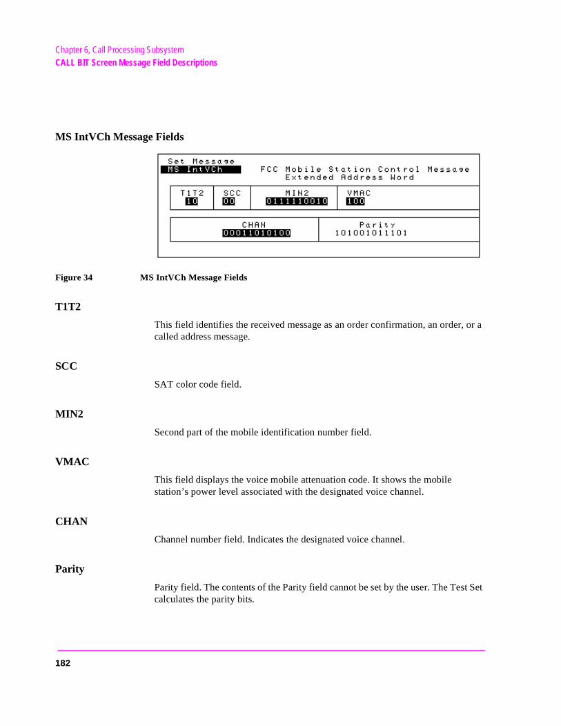
Chapter 6, Call Processing SubsystemCALL BIT Screen Message Field Descriptions
t Set
MS IntVCh Message Fields
Figure 34 MS IntVCh Message Fields
T1T2
This field identifies the received message as an order confirmation, an order, or a called address message.
SCC
SAT color code field.
MIN2
Second part of the mobile identification number field.
VMAC
This field displays the voice mobile attenuation code. It shows the mobile station’s power level associated with the designated voice channel.
CHAN
Channel number field. Indicates the designated voice channel.
Parity
Parity field. The contents of the Parity field cannot be set by the user. The Tescalculates the parity bits.
182
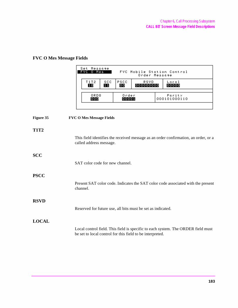
Chapter 6, Call Processing SubsystemCALL BIT Screen Message Field Descriptions
FVC O Mes Message Fields
Figure 35 FVC O Mes Message Fields
T1T2
This field identifies the received message as an order confirmation, an order, or a called address message.
SCC
SAT color code for new channel.
PSCC
Present SAT color code. Indicates the SAT color code associated with the present channel.
RSVD
Reserved for future use, all bits must be set as indicated.
LOCAL
Local control field. This field is specific to each system. The ORDER field must be set to local control for this field to be interpreted.
183
Chapter 6, Call Processing SubsystemCALL BIT Screen Message Field Descriptions
ORDQ
Order qualifier field. Qualifies the order to a specific action.
ORDER
Order field. Identifies the order type.
Parity
Parity field. The contents of the Parity field cannot be set by the user. The Test Set calculates the parity bits.
184
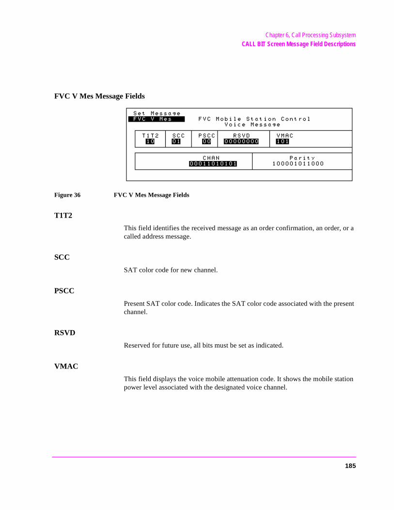
Chapter 6, Call Processing SubsystemCALL BIT Screen Message Field Descriptions
FVC V Mes Message Fields
Figure 36 FVC V Mes Message Fields
T1T2
This field identifies the received message as an order confirmation, an order, or a called address message.
SCC
SAT color code for new channel.
PSCC
Present SAT color code. Indicates the SAT color code associated with the present channel.
RSVD
Reserved for future use, all bits must be set as indicated.
VMAC
This field displays the voice mobile attenuation code. It shows the mobile station power level associated with the designated voice channel.
185

Chapter 6, Call Processing SubsystemCALL BIT Screen Message Field Descriptions
CHAN
Channel number field. Indicates the designated voice channel.
Parity
Parity field. The contents of the Parity field cannot be set by the user. The Test Set calculates the parity bits.
186
Chapter 6, Call Processing SubsystemUsing the CALL BIT Screen
y
L
st Set
trol
ering sing
ging
ALLmode.station
t thatnment.
odecessing
Using the CALL BIT Screen
Selecting The Message Content Generation Method
The contents (i.e. bit patterns) of the signaling messages sent to the mobile station on the forward control channel and the forward voice channel are generated using one of two methods. Method 1 uses the formats defined in the applicable industry standard to build the contents of the signaling messages. Method 2 uses the bit patterns which the user defines on the CALL BIT screen to build the contents of the signaling messages.
The Data Spec field on the CALL BIT screen determines which method will be used to build the contents of the signaling messages.
• Std -The Test Set will use the signaling formats defined in the applicable industrstandard to build the forward control channel and forward voice channel signalingmessages. The Test Set will use the contents of the applicable fields on the CALCONTROL screen and the CALL CONFIGURE screen to obtain information necessary to build the messages. Whenever a signaling message is used, the Tewill update the contents of all fields in that message on the CALL BIT screen.
• Bits -Use the bit patterns as set on the CALL BIT screen to build all forward conchannel and forward voice channel signaling messages. For any call processing function (that is, setting the message stream on the active control channel, registthe mobile station, paging the mobile station, handing off the mobile station or releathe mobile station) the user is responsible for setting the contents of all signalingmessages used in that function. The Call Processing Subsystem uses the messaprotocol as defined in the applicable industry standard.
NOTE: The contents of the applicable fields on the CALL CONTROL screen and the CCONFIGURE screen are not updated to reflect any changes made while in the Bits There is no coupling between the Bits mode and the Test Set. For example: if a mobile was actively connected to the Test Set on a voice channel and the user changed the CHAN fieldon the forward voice channel mobile station control message (FVC V Mes) and senmessage to the mobile station, the mobile station would change its voice channel assigHowever, the Test Set will stay on the voice channel assignment specified in the Chan: fieldon the CALL CONTROL screen. This situation will result in a dropped call. The Bits mshould not be used to change any parameter that can be set on any other Call ProSubsystem screen.
187
Chapter 6, Call Processing SubsystemUsing the CALL BIT Screen
System Operation When Data Spec Field Set to Std
When the Data Spec field is set to Std the Test Set builds the signaling messages by first examining the fields which contain the information needed to build the messages (i.e. SID, BIS, SAT Tone, VMAC, etc.). After obtaining the necessary information the Test Set builds the bit patterns according to the signaling formats specified in the applicable industry standard.
For example: if the type of cellular system being emulated is AMPS and the SID field on the CALL PROC screen was set to 231, the SID1 field in the System Parameter Overhead Message (SPC WORD1) would be set to 00000001110011 (the 14 most significant bits of the system identification number) as defined by the EIA/TIA-553 Mobile Station - Land Station Compatibility Specification.
When the Data Spec field is set to Std, the contents of the applicable message(s) on the CALL BIT screen are updated with the bit patterns generated using the signaling formats defined in the applicable industry standard whenever that signaling message is sent to the mobile station. This feature allows a user to set the Data Spec field to Std, select a message of interest, perform a call processing function, and view the bit patterns generated using the signaling formats defined in the applicable industry standard.
It is important to note individual messages can be used more than once during a messaging protocol. The contents of any message viewed on the CALL BIT screen when the Data Spec field is set to Std will reflect the message contents for the last time the message was used in a messaging protocol.
For example: if the Call Processing Subsystem is in the active state and the user selects the Register field, a registration message will be sent to the mobile station. When the registration completes the Call Processing Subsystem returns to the active state. The contents of some messages (such as the System Parameter Overhead Message Word 1) will reflect the correct settings for the active state, not the register state, since the messages are currently being used in the active state.
188
Chapter 6, Call Processing SubsystemUsing the CALL BIT Screen
System Operation When Data Spec Field Set to Bits
When the Data Spec field is set to Bits, the Test Set builds the signaling messages using only the bit patterns set on the CALL BIT screen whenever a call processing function is executed which uses any of the available messages. The Test Set calculates the contents of the Parity field using the coding algorithms specified in the industry standard for the selected system (that is, the system specified in the System Type field on the CALL CONTROL screen).
By definition, the Test Set must meet the timing requirements of the industry standard for the selected system. Therefore, depending upon the state of the Call Processing Subsystem (i.e. Active, Register, Page, Access, or Connect) and the frequency with which a particular call processing protocol uses a particular message, it may not be possible to modify the contents of more than one field in a message before it is sent to the mobile station.
For example: in the AMPS system, the system parameter overhead message must be sent every 0.8 +/- 0.3 seconds on the forward control channel. Given this timing requirement it is highly unlikely that, while in the active state, a user could modify more than one field before the message was sent to the mobile station.
There is no functionality in the Test Set to allow an entire message to be modified and then inserted into a messaging protocol at a specific location at a specific time. This functionality requires a protocol analyzer.
When in the Bits mode the Test Set provides the messaging protocol for the user (that is, for a desired call processing function the correct message(s) will be sent at the correct time(s) according to the standard). It is the responsibility of the user to generate the contents of all the messages which will be used in a particular call processing function.
For example: if the Call Processing Subsystem was in the active state and the operator wished to register the mobile station from the Bits mode, the user would have to set the contents of all the messages used in the registration before selecting the Register field to start the registration process.
NOTE: No error checking is done on the bit patterns. The bit patterns are used but are not checkedagainst any industry standard. It is the responsibility of the user to ensure that the bit patternsset in the CALL BIT screen are correct when the Data Spec field is set to Bits.Unexpected operation of the mobile station can occur if the contents of the signaling messagesare incorrect.
189
Chapter 6, Call Processing SubsystemUsing the CALL BIT Screen
Changing the Content of a Message Field
Perform the following steps to change the contents of a message field:
1. Position the cursor on the Data Spec field and select Bits.2. Select the Set Message field. A Choices: menu is displayed listing the available
messages. Select the desired message. The message fields will be displayed on the screen.
3. Select the desired bit field. A Choices: menu will be displayed. Using the Choic-es: menu enter the desired bit pattern. Select Done from the Choices: menu when the desired bit pattern has been entered.
When a message field is being modified the original contents of the field (that is - the contents of the field before modification was started) is sent whenever the message is used in a messaging protocol. The new contents are not used until Done is selected from the Choices: menu. Use the CANCEL key to abort a modification. If the CANCEL key is selected the original field contents are restored.
NOTE: If a message field is modified while the Data Spec field is set to Std the modified contentswill be overwritten with the bit patterns generated using the signaling formats defined in theapplicable industry standard immediately after Done is selected from the Choices: menu.
190
Chapter 6, Call Processing SubsystemUsing the CALL BIT Screen
Typical Example
The following example illustrates the use of the CALL BIT screen. In this example an AMPS mobile station is brought up on a voice channel and then handed off to a new voice channel assignment. The contents of the FVC V Msg message, which was set when the first handoff occurred, is then modified from the CALL BIT screen. The mobile station is then handed off again by sending the modified message to the mobile station from the CALL BIT screen.
1. Ensure that the Test Set is in the connected state. See "Page a Mobile Station" on page 133 for information on how to bring a mobile station up on a voice channel.
2. If the CALL CONTROL screen is not displayed, select CALL CNTL under the To Screen menu. The CALL CONTROL screen will be displayed.
3. Position the cursor on the Display field and select Data.4. Select the Chan: field and enter a new, valid voice channel number.5. Select the Pwr Lvl: field enter a new, valid mobile station power level.6. Select the SAT: field and enter a new, valid SAT frequency.7. Select the Handoff field. The Access annunciator will light while the Test Set sig-
nals the mobile station with the handoff information. If the mobile responds properly, it will stop transmitting on the current voice channel, switch to the new voice channel assignment, and transpond the new SAT frequency assignment. When the Test Set de-tects that this has happened the Connect annunciator is lit indicating that the handoff was successful. The left-hand fields in the Voice Channel Assignment section will be updated with the new voice channel assignment information.
8. Select CALL BIT from the To Screen menu. The CALL BIT screen will be dis-played.
9. Position the cursor on the Data Spec field and select Bits.10. Select the Set Message field and select FVC V Msg.11. Select the VMAC field in the FVC V Msg and set it to 101 (this corresponds to a mobile
station power level of 5 - reference EIA/TIA-553 Mobile Station - Land Station Com-patibility Specification, September 1989, page 2-2, Table 2.1.2-1).
12. Select the Handoff field. The Access annunciator will light while the Test Set sig-nals the mobile station with the handoff information. If the mobile responds properly, it will stop transmitting on the current voice channel, and start transmitting on the same channel with a power level of 5 (note that the channel assignment and SAT assignment were not modified in this example, the mobile station simply switched to the same channel with the same SAT assignment). When the Test Set detects that this has hap-pened, the Connect annunciator is lit indicating that the handoff was successful. The mobile station power level after the handoff should be power level 5.
13. Position the cursor on the Data Spec field and select Std.
191
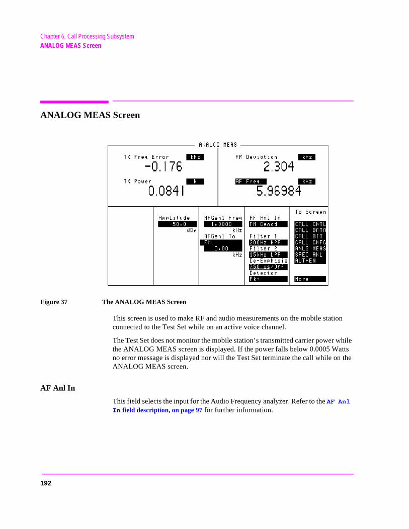
Chapter 6, Call Processing SubsystemANALOG MEAS Screen
the
ANALOG MEAS Screen
Figure 37 The ANALOG MEAS Screen
This screen is used to make RF and audio measurements on the mobile station connected to the Test Set while on an active voice channel.
The Test Set does not monitor the mobile station’s transmitted carrier power while the ANALOG MEAS screen is displayed. If the power falls below 0.0005 Wattsno error message is displayed nor will the Test Set terminate the call while onANALOG MEAS screen.
AF Anl In
This field selects the input for the Audio Frequency analyzer. Refer to the AF Anl
In field description, on page 97 for further information.
192
Chapter 6, Call Processing SubsystemANALOG MEAS Screen
ld
put
AF Freq
This field is a one-of-many field used to select the type of measurement to be made by the Audio Frequency Analyzer on the audio signal being measured. Refer to the SINAD field description, on page 106 for descriptions of the measurements available.
AFGen1 Freq
This field sets the output frequency of Audio Frequency Generator 1. Refer to the AFGen1 Freq field description, on page 432 for further information.
AFGen1 To
This field has two fields:
• the upper field sets the destination port for Audio Frequency Generator 1 • FM -RF Generator FM modulator • AM -RF Generator AM modulator• Audio Out -AUDIO OUT connector on front panel of Test Set
• the lower field sets the:• FM modulation deviation if the upper field set to FM • AM modulation depth if the upper field set to AM• amplitude of audio signal (volts RMS) at the AUDIO OUT connector if upper fie
is set to Audio Out
For testing mobile stations, the upper field is normally set to FM, and the lower field set to the desired FM deviation in kHz. Refer to the AFGen1 Freq field description, on page 432 for further information.
Amplitude
This field sets the output power of the Test Sets’s transmitter (that is, the outpower of the Test Set’s RF Generator). Refer to the Amplitude field description, on page 433 for further information.
De-Emphasis
This field is used to select or bypass the 750 µs de-emphasis filter network used tocondition the audio signal before being analyzed by the Audio Frequency Analyzer. Refer to the De-Emphasis field description, on page 100 for further information.
193
Chapter 6, Call Processing SubsystemANALOG MEAS Screen
Detector
This field is used to select the type of detector used to measure the amplitude of the audio signal being measured. Refer to the Detector field description, on page 101 for descriptions of the detectors available.
Filter 1
This field selects one of several standard or optional audio frequency filters which can be used to condition the audio signal before being analyzed by the Audio Frequency Analyzer. Refer to the Filter 1 and Filter 2 field description, on page 102 for further information.
Filter 2
This field selects one of several standard or optional audio frequency filters which can be used to condition the audio signal before being analyzed by the Audio Frequency Analyzer. Refer to the Filter 1 and Filter 2 field description, on page 102 for further information.
FM Deviation
This field displays the measured FM deviation of the carrier being transmitted by the mobile station. Four dashes (----) indicate that no carrier is present to measure.
TX Freq Error
This field displays the frequency error (error = assigned carrier frequency - measured carrier frequency) of the carrier being transmitted by the mobile station. Four dashes (----) indicates that there is no carrier frequency present to measure.
TX Power
This field displays the measured RF power of the carrier being transmitted by the mobile station. Four dashes (----) indicates that there is no carrier present to measure.
194

Chapter 6, Call Processing SubsystemUsing the ANALOG MEAS Screen
ields een
DIO the .
the
bile
Using the ANALOG MEAS Screen
The ANALOG MEAS screen combines some of the Test Set’s Audio Analyzer fields and some of the Test Set’s RF Generator fields onto one screen for thepurpose of testing the audio characteristics of the mobile station. Only those fwhich are pertinent to testing the mobile stations audio characteristics have bcombined onto the ANALOG MEAS screen. The Test Set must be in the connected state (that is, the Connect annunciator is lit) in order to use the ANALOG MEAS screen.
The mobile station’s speaker output must be connected to the Test Set’s AUIN connector and the mobile station’s microphone input must be connected toTest Set’s AUDIO OUT connector in order to use the ANALOG MEAS screenRefer to figure 14, "Connecting a Mobile Station to the Test Set," on page 115 for connection information. If the mobile station does not have audio connectionsANALOG MEAS screen cannot be used.
There are a wide variety of audio measurements which can be made from the ANALOG MEAS screen. The following examples illustrate how to make a typical mobile station receiver measurement (RF Sensitivity) and a typical mostation transmitter measurement (FM Hum and Noise). Refer to the HP 8920A RF Communications Test Set Applications Handbook, section “Testing FM Radios” for further information on using the Test Set’s Audio Analyzer to make audio measurements.
195
Chapter 6, Call Processing SubsystemUsing the ANALOG MEAS Screen
d therder
ity
ce
ed. char- Un-n the
To Make an RF Sensitivity Measurement1. If not already done, condition the Test Set. See "Conditioning the Test Set for Call
Processing" on page 130 for further information.2. If not already done, configure the Test Set. See "Configure the Test Set" on page 131
for further information.3. Connect the mobile station to the Test Set as shown in Figure 14, "Connecting a Mo-
bile Station to the Test Set," on page 115.
NOTE: The mobile station’s speaker output must be connected to the Test Set’s AUDIO IN anmobile station’s microphone input must be connected to the Test Set’s AUDIO OUT in oto use the ANALOG MEAS screen.
4. Turn on the mobile station.5. Ensure that the Test Set is in the connected state. See "Page a Mobile Station" on
page 133 for information on how to bring a mobile station up on a voice channel.6. If the ANALOG MEAS screen is not displayed, select the ANLG MEAS field from the
To Screen menu. The ANALOG MEAS screen will be displayed.7. The following example illustrates how to make a 12 dB SINAD Receiver Sensitiv
measurement:a. Select the AFGen1 Freq field and set it to 1 kHz.b. Select the upper AFGen1 To field and set it to FM.c. Select the lower AFGen1 To field and set it to 8 kHz.d. Select the AF Anl In field and select Audio In.e. Select the Filter 1 field and select C MESSAGE.f. Select the Filter 2 field and select >99kHz LP.g. Position the cursor on the De-Emphasis field and select Off.h. Select the Detector field and select RMS.i. Select the AF Freq measurement field and select SINAD.j. Select the Amplitude field and begin to lower the transmitted base station voi
channel power until 12 dB SINAD is reached.k. The mobile station might mute or drop off the air before a 12 dB SINAD is reach
The performance of the mobile station at low RF levels is dependent upon theacteristics of the mobile station (that is, what type of system it is designed for).like a real base station, the Test Set does not perform any protocol functions ovoice channel.
196
Chapter 6, Call Processing SubsystemUsing the ANALOG MEAS Screen
d therder
akingssiblet the
nt:
zero
To Make an FM Hum and Noise Measurement1. If not already done, condition the Test Set. See "Conditioning the Test Set for Call
Processing" on page 130 for further information.2. If not already done, configure the Test Set. See "Configure the Test Set" on page 131
for further information.3. Connect the mobile station to the Test Set as shown in Figure 14, "Connecting a Mo-
bile Station to the Test Set," on page 115.
NOTE: The mobile station’s speaker output must be connected to the Test Set’s AUDIO IN anmobile station’s microphone input must be connected to the Test Set’s AUDIO OUT in oto use the ANALOG MEAS screen.
4. Turn on the mobile station.
Ensure that the Test Set is in the connected state. See "Page a Mobile Station" on page 133 for information on how to bring a mobile station up on a voice channel.
5. If the ANALOG MEAS screen is not displayed, select the ANLG MEAS field from the To Screen menu. The ANALOG MEAS screen will be displayed.
NOTE: It is recommended that the mobile station’s microphone be muted, if possible, when mmeasurements on the mobile stations RF carrier. If the microphone is not muted it is pofor extraneous noise to be picked up by the microphone and adversely affecmeasurements.
6. The following example illustrates how to make a FM Hum and Noise measuremea. Select the Amplitude field and set it to −47 dBm.b. Select the AFGen1 Freq field and set it to 1 kHz.c. Select the upper AFGen1 To field and set it to Audio Out.d. Select the AF Anl In field and select FM Demod.e. Select the Filter 1 field and select C MESSAGE.f. Select the Filter 2 field and select >99kHz LP.g. Position the cursor on the De-Emphasis field and select 750 us.h. Select the Detector field and select PK+.i. Select the measurement field and select AF Freq.j. Select the lower AFGen1 To field and adjust the signal level until the FM Devi-
ation field on the upper portion of the CRT reads 8 kHz.k. Select the Detector field and select RMS.l. Select the FM Deviation field.m. Press the blue SHIFT key, the INCR -10 key, then the ENTER key. This sets a
reference point.n. Select the lower AFGen1 To field and press the ON/OFF key. This turns off the
modulating signal to the mobile station transmitter.o. The FM Hum and Noise figure is displayed in the FM Deviation field.
197
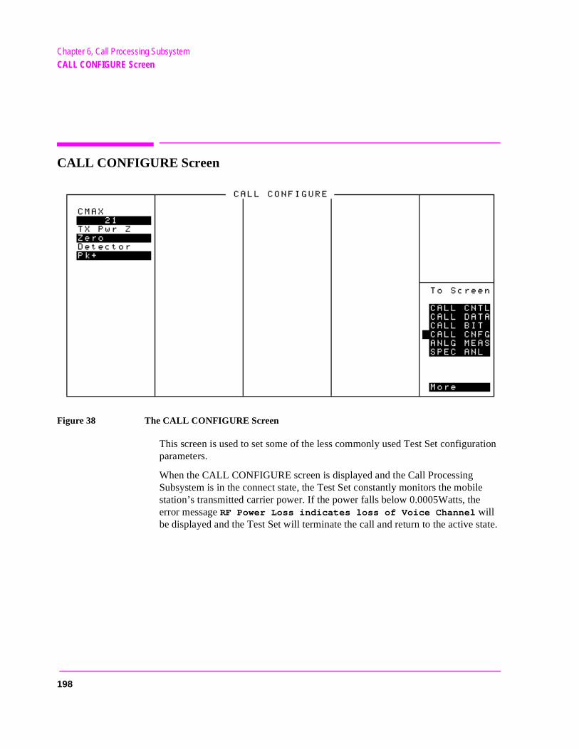
Chapter 6, Call Processing SubsystemCALL CONFIGURE Screen
tate.
CALL CONFIGURE Screen
Figure 38 The CALL CONFIGURE Screen
This screen is used to set some of the less commonly used Test Set configuration parameters.
When the CALL CONFIGURE screen is displayed and the Call Processing Subsystem is in the connect state, the Test Set constantly monitors the mobile station’s transmitted carrier power. If the power falls below 0.0005Watts, the error message RF Power Loss indicates loss of Voice Channel will be displayed and the Test Set will terminate the call and return to the active s
198

Chapter 6, Call Processing SubsystemCALL CONFIGURE Screen
ing the power
NOTE: In order to ensure that the Test Set makes the correct decisions regarding the presence of themobile stations’s RF carrier, the Test Set’s RF power meter should be zeroed before usCall Processing Subsystem. Failure to zero the power meter can result in erroneous RFmeasurements. See "Conditioning the Test Set for Call Processing" on page 130 forinformation on zeroing the RF Power meter manually.
CMAX
The CMAX field sets the number of access channels in the system. This will determine how many channels must be scanned by the mobile station when trying to access the Test Set. The value of this field will affect the time required for the mobile station to connect with the Test Set.
Detector
This field is used to select the type of detector used to measure the amplitude of the audio signal being measured. Refer to the Detector field description, on page 101 for descriptions of the detectors available.
TX Pwr Zero
The TX Pwr Zero function establishes a 0.0000 W reference for measuring RF power at the RF IN/OUT port. See "TX Pwr Zero" on page 427 for further information.
CAUTION: RF power must not be applied while zeroing. Set the RF GENERATOR screen’s Amplitudefield to off to prevent internal cross-coupling into the power detector while zeroing.
199

Chapter 6, Call Processing SubsystemCALL CONFIGURE Screen
200
7
Configure Screen
The CONFIGURE screen defines a number of general operating functions, such as date and time, screen intensity, and beeper volume. It is also used to define some RF signal parameters, such as RF Generator/Analyzer offset, channel standards and characteristics, and signal loss/gain compensation.
201
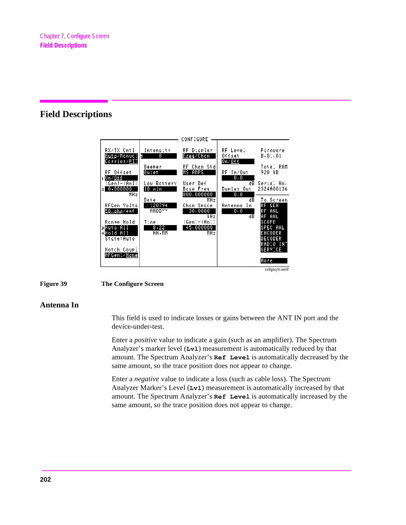
Chapter 7, Configure ScreenField Descriptions
t
Field Descriptions
Figure 39 The Configure Screen
Antenna In
This field is used to indicate losses or gains between the ANT IN port and the device-under-test.
Enter a positive value to indicate a gain (such as an amplifier). The Spectrum Analyzer’s marker level (Lvl) measurement is automatically reduced by that amount. The Spectrum Analyzer’s Ref Level is automatically decreased by thesame amount, so the trace position does not appear to change.
Enter a negative value to indicate a loss (such as cable loss). The Spectrum Analyzer Marker’s Level (Lvl) measurement is automatically increased by thaamount. The Spectrum Analyzer’s Ref Level is automatically increased by thesame amount, so the trace position does not appear to change.
cnfgscrn.wmf
202

Chapter 7, Configure ScreenField Descriptions
in
This field is only used when the RF Level Offset field is set to On.
See Also
RF Level Offset field description, on page 211
Base Freq (User Defined)
The Base Frequency field sets the RF Generator reference for channel 0 (zero) when the RF Chan Std field is set to USER-DEF, and the RF Display field is set to Chan.
Channel frequencies are calculated using the following formula:
Channel N = Base Frequency + (N)(Channel Spacing)
The Base Frequency is calculated using the following formula:
Base Frequency = Channel 1 Frequency - Channel Spacing
For example, if your multi-channel radio’s lowest receive channel frequency is 870.030 MHz and the system channel spacing is 30 KHz, you would enter 870
MHz in this field. You would also use the Chan Space and (Gen)-(Anl) fields to tell the Test Set where other transmit and receive channel frequencies arerelation to the base frequency, and whether or not the system is duplex.
Operating Considerations
The value of this field is only used if the RF Display field is set to Chan, and the RF Chan Std field is set to USER-DEF.
See Also
Chan Space (User Defined) field description, on page 204(Gen)-(Anl) field description, on page 206RF Chan Std field description, on page 209RF Display field description, on page 210
203
Chapter 7, Configure ScreenField Descriptions
l. If
Beeper
This field changes the audio beeper volume by selecting the desired level from a list of choices. The beeper always beeps when the instrument is turned on, regardless of this setting.
Operating Considerations
The beeper alerts you any time a message is displayed. Since a message may be removed from the screen before you notice it, it is better to leave the beeper on to alert you to errors during operation.
The beeper’s volume setting is retained when the instrument is turned off.
Chan Space (User Defined)
This field specifies the RF channel spacing when the RF Display field is set to Chan, and the RF Chan Std field is set to USER-DEF.
For example, entering 25 kHz causes a 25 kHz spacing between each channethe receive frequency for channel 1 is 150.500 MHz, channel 2’s receive frequency would be 150.525 MHz.
Operating Considerations
The value of this field is only used if the RF Display field is set to Chan, and the RF Chan Std field is set to USER-DEF.
See Also
(Gen)-(Anl) field description, on page 206RF Chan Std field description, on page 209Base Freq (User Defined) field description, on page 203
204
Chapter 7, Configure ScreenField Descriptions
or’s
al
evel
then
Date
This field specifies the current date for the internal clock. The date can be read by a controller using HP-IB and printed on test results.
The format is MMDDYY (Month Day Year), using two digits for each term. When entering months January through September (01-09), the leading zero is not displayed when entered. Example; May 5, 1993 is entered as 050593, but is displayed as 50593.
The internal clock still functions when the instrument is turned off.
Duplex Out
This field is used to indicate losses or gains between the DUPLEX OUT port and the device-under-test.
• Enter a positive value to indicate a gain (such as an amplifier gain). The RF Generatlevel is automatically set that amount below what is indicated in the RF Generator’s Amplitude field. (Example; if this value is 10 dB, and the Amplitude field shows 0 dBm, the actual level out this port is −10 dBm.) The value at the output of the externamplifier should then be at the level indicated in the Amplitude field.
• Enter a negative value to indicate a loss (such as cable loss). The RF Generator’s lis automatically set that amount above what is indicated in the RF Generator’s Ampli-tude field to compensate. The value at the opposite end of the cable (loss) shouldbe at the level indicated in the Amplitude field; unless the resulting RF Generator setting exceeds the maximum output level, then an error occurs: Input value out of range. In that case, reduce the Amplitude setting, or decrease the Duplex Out value.
This field is only used when the RF Level Offset field is set to On.
Firmware
This field displays the current firmware revision for your Test Set. The revision number is automatically changed when updated firmware is installed.
205
Chapter 7, Configure ScreenField Descriptions
t
mit
(Gen)-(Anl)
This field is used with the RF Offset field to specify the amount of frequency offset between the RF Generator and RF Analyzer.
This field is not displayed when the RF Display field is set to Chan (the offset is automatically set when using channel tuning).
See Also
"Setting an RF Generator/Analyzer Offset" on page 79
(Gen)-(Anl) (User Defined)
This field defines the receiver-transmitter frequency offset when using User Defined channel operation.
Use a positive value when the radio’s receive frequency is higher than the transmifrequency (such as 45 MHz)
Use a negative value when the radio’s receive frequency is lower than the transfrequency (such as −45 MHz).
Operating Considerations
The value of this field is only used if the RF Display field is set to Chan, and the RF Chan Std field is set to USER-DEF.
See Also
Chan Space (User Defined) field description, on page 204RF Chan Std field description, on page 209RF Display field description, on page 210
206
Chapter 7, Configure ScreenField Descriptions
ed),
anel by
z
Intensity
This field adjusts the screen intensity from a setting of 1 (very dim) to 8 (bright). If the setting is set too low, the screen can no longer be read. If you can’t read the screen, and you don’t know where the cursor is (or even what screen is displaypress [PRESET], and re-access the CONFIGURE screen. The cursor automatically goes to this field at that point. Press [8], [ENTER] to set the maximum intensity, and re-adjust if desired.
This setting is retained when the instrument is turned off.
Low Battery
This setting is used during battery (dc) operation to alert you when no front-pcontrols are used within the specified amount of time. The setting is changedselecting this field, then choosing the setting from a list of choices.
This setting is retained when the instrument is turned off.
Notch Coupl
This field selects if the Notch Freq setting of the AF ANALYZER screen is coupled to the AF Gen1 Freq setting. When set to None, the notch filter and AF Generator 1 do not interact. When set to AFGen1 (coupled), the settings track each other unless the AF Generator’s frequency is set outside the 300 Hz to 10 kHlimits of the notch filter1
1. Optional for the HP 8921A.
207
Chapter 7, Configure ScreenField Descriptions
g
Range Hold
These fields enable/disable several autoranging and autotuning routines.
Auto All enables these routines, providing automatic adjustment when making AF or RF measurements.
Hold All disables these routines, requiring you to manually set the affected settings.
The following fields are affected by the Range Hold field:
• RX/TX Cntl in the CONFIGURE screen.
• Tune Mode in the TX TEST, DUPLEX TEST, and RF ANALYZER screens.
• Input Atten in the RF ANALYZER and SPECTRUM ANALYZER screens.
• Gain Cntl in the AF ANALYZER screen. This field controls three AF gain settinfields:
Input Gain
De-Emp Gain
Notch Gain
Operating Considerations
The Hold All setting is primarily used when the instrument is operated by remote control, such as in an automated test system.
Unless you have very specific reasons for disabling the automatic functions, you should set this field to Auto All when operating the instrument manually.
See Also
Programmer’s Guide
208
Chapter 7, Configure ScreenField Descriptions
bile
sing
en
RF Chan Std
Use the RF channel standard field to select the channel standard for the radio-under-test. The RF Generator’s and the RF Analyzer’s frequencies are automatically set to correspond to the channel number entered in the RF Channel field. RF Channel replaces the Amplitude and Tune Freq fields on several screens when channel tuning is used.
Each standard has a prefix code that indicates what type of radio to test; mostation (MS) or land station (LS). For example, if you are testing an AMPS mobile, select MS AMPS.
For the NAMPS standards, a third letter is added indicating which frequency band is used: upper, middle, or lower. For example, when testing a mobile station uthe lower band, choose MSL NAMPS. Testing a land station using the upper bandyou would select LSU NAMPS.
The USER-DEF selection is used to define your own channel assignments. Whselected, you enter the Base Freq, Chan Space, and (Gen)-(Anl) settings.
See Also
Base Freq (User Defined) field description, on page 203Chan Space (User Defined) field description, on page 204(Gen)-(Anl) field description, on page 206
209
Chapter 7, Configure ScreenField Descriptions
r’s
, you r and
o
cross
des.
RF Display
This field selects the format for entering the RF Generator’s and RF Analyzefrequencies:
• When Freq is selected, you enter the RF Generator’s and the RF Analyzer’s frequencies directly using the keypad or knob.
• When Chan is selected, the RF Gen Freq and Tune Freq fields on all screens arereplaced by the RF Channel field, and only the channel number is entered and displayed.
Channel tuning eliminates the need to enter transmit and receive frequencies directly into the Test Set. Once your radio’s RF channel standard is selectedonly have to enter the channel number to automatically set the RF GeneratoRF Analyzer to the correct frequencies.
Operating Considerations
When channel tuning is used, the RF Analyzer is set to manual tuning. The Tune Mode field on the TX TEST, DUPLEX TEST, and RF ANALYZER screens is nlonger displayed. As a result, the TX Freq Error measurement is displayed (since the TX Frequency measurement is only displayed when the Tune Mode field is set to Auto).
See Also
RF Chan Std field description, on page 209
RF Gen Volts
This field specifies whether you want RF voltages expressed as the voltage aa 50 ohm load, or the open circuit voltage (emf).
Operating Considerations
This setting affects the RF Generator’s and the Tracking Generator’s amplitu
210
Chapter 7, Configure ScreenField Descriptions
) lev--
(or
ent
RF In/Out
This field is used to indicate losses or gains between the RF IN/OUT port and the device-under-test.
• Enter a positive value to indicate a gain (such as an amplifier gain). When the RF IN/OUT port is used as an output, the RF Generator’s (or Tracking Generator’sel is automatically set the specified amount below what is indicated in the RF Generator’s Amplitude field. Example; if this value is 10 dB, and the Amplitude field shows 0 dBm, the actual level out of this port is −10 dBm.
When this port is used as an input, the TX Power measurement and Spectrum Ana-lyzer’s Marker Level (Lvl) are automatically reduced by that amount.
• Enter a negative value to indicate a loss (such as cable loss). The RF Generator’s Tracking Generator’s) level out this port is automatically set that amount above what is indicated in the RF Generator’s Amplitude field.
When used as an input, the TX Power and the Spectrum Analyzer’s marker level (Lvl) measurements are increased by that amount.
This field is only used when the RF Level Offset field is set to On.
See Also
RF Level Offset field description, on page 211
RF Level Offset
This field enables/disables the RF level offsets entered in the RF In/Out, Duplex Out, and Antenna In fields below it.
• When set to On, the RF Generator’s amplitude and RF Analyzer’s power measuremare offset by the values entered in these fields.
• When set to Off, the values in these fields are ignored.
See Also
Antenna In field description, on page 202Duplex Out field description, on page 205RF Chan Std field description, on page 209
211
Chapter 7, Configure ScreenField Descriptions
s),
RF Offset
This field is displayed when the RF Display field has Freq selected.
This field enables/disables the RF Generator−RF Analyzer frequency offset specified in the (Gen)-(Anl) field below it.
Operating Considerations
When an RF offset is used, changing the RF Generator’s frequency or RF Analyzer’s tune frequency automatically alters the other setting. On screens where both fields are not shown (such as the RX TEST and TX TEST screenyou will not see the corresponding field change.
See Also
"Setting an RF Generator/Analyzer Offset" on page 79
212
Chapter 7, Configure ScreenField Descriptions
eens
ra-
n to EST
ST nnec-nger
T port
.
RX/TX Cntl
This function controls automatic screen changes between the RX TEST and TX TEST screens during radio testing. It is divided into two fields:
The Auto/Manual field enables/disables automatic switching between the RX TEST and TX TEST screens under certain testing conditions.
• Auto allows automatic screen changes between the RX TEST and TX TEST scrwhile testing radios.
• Manual requires you to select the RX TEST or TX TEST screen when performingdio tests.
The Carrier/PTT field specifies the condition that will cause automatic screen changes.
• Carrier causes the instrument to automatically switch from the RX TEST screethe TX TEST screen when an RF carrier is detected. The screen returns to RX Twhen the carrier is no longer detected.
• PTT (Push-To-Talk) causes the instrument to automatically switch from the TX TEscreen to the RX TEST screen when a microphone connected to the MIC/ACC cotor is keyed. The screen changes back to TX TEST when the microphone is no lokeyed.
Operating Considerations
CAUTION: The Test Set can be damaged by connecting a reverse-power signal to the DUPLEX OUof >200 mW.
If Auto and Carrier are used together, the screen may continuously change between RX TEST and TX TEST. This only occurs if the RF IN/OUT port is used with the RF Generator Amplitude set ≥ 35 dBm (a much higher level than is typically used for receiver tests). To prevent this problem, set the Amplitude≤35 dBm or Off, or use the DUPLEX OUT port for the RF Generator’s output
213
Chapter 7, Configure ScreenField Descriptions
d
Serial No.
This field displays the serial number of the Test Set.
Time
This field sets the time-of-day for the instrument’s 24 hour clock. (Example, 4:53 PM is entered 16:53)
Operating Considerations
The internal clock still functions when the instrument is turned off.
Total RAM
This field displays the total amount of RAM available for IBASIC programs ansave/recall registers.
214
8
Signaling Decoder Screen
215
Chapter 8, Signaling Decoder ScreenField Descriptions for Decoder Modes
Field Descriptions for Decoder Modes
The Signaling Decoder analyzes different data-encoded signaling formats. The format is selected in the Mode field in any of the decoder’s screens.
A list of standards for each format is displayed by selecting the Standard field in any screen.
Separate screen and field descriptions are given for each screen. The descriptions are listed in the following order:
• AMPS-TACS/NAMPS-NTACS
• CDCSS (Continuous Digital Controlled Squelch System)
• Digital Paging
• DTMF (Dual-Tone Multi-Frequency) Sequence
• EDACS (Enhanced Digital Access Communications System)
• Function Generator
• LTR (Logic Trunked Radio: Registered Trademark of EF Johnson Company)
• MPT 1327
• NMT (Nordic Mobile Telephone) encoder and decoder
• Tone Sequence
The Decoder’s Signal Source
The decoder always gets its signal immediately after the de-emphasis network of the AF Analyzer. De-emphasis can be turned on or off on the AF ANALYZER screen, or can be controlled while using the decoder by assigning a global USER key to the De-Emphasis field. Refer to the AF ANALYZER screen’s field descriptions and functional block diagram in chapter 5, "AF Analyzer Screen," on page 95.
Decoder Frequency Measurements
The decoder uses a different timebase for frequency counting than the AF Analyzer. Therefore, their measurements may be different when measuring the same signal (by a very small amount).
216
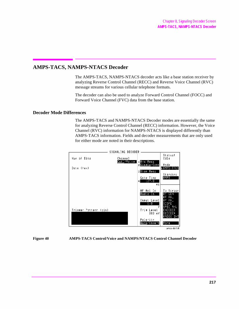
Chapter 8, Signaling Decoder ScreenAMPS-TACS, NAMPS-NTACS Decoder
AMPS-TACS, NAMPS-NTACS Decoder
The AMPS-TACS, NAMPS-NTACS decoder acts like a base station receiver by analyzing Reverse Control Channel (RECC) and Reverse Voice Channel (RVC) message streams for various cellular telephone formats.
The decoder can also be used to analyze Forward Control Channel (FOCC) and Forward Voice Channel (FVC) data from the base station.
Decoder Mode Differences
The AMPS-TACS and NAMPS-NTACS Decoder modes are essentially the same for analyzing Reverse Control Channel (RECC) information. However, the Voice Channel (RVC) information for NAMPS-NTACS is displayed differently than AMPS-TACS information. Fields and decoder measurements that are only used for either mode are noted in their descriptions.
Figure 40 AMPS-TACS Control/Voice and NAMPS/NTACS Control Channel Decoder
217
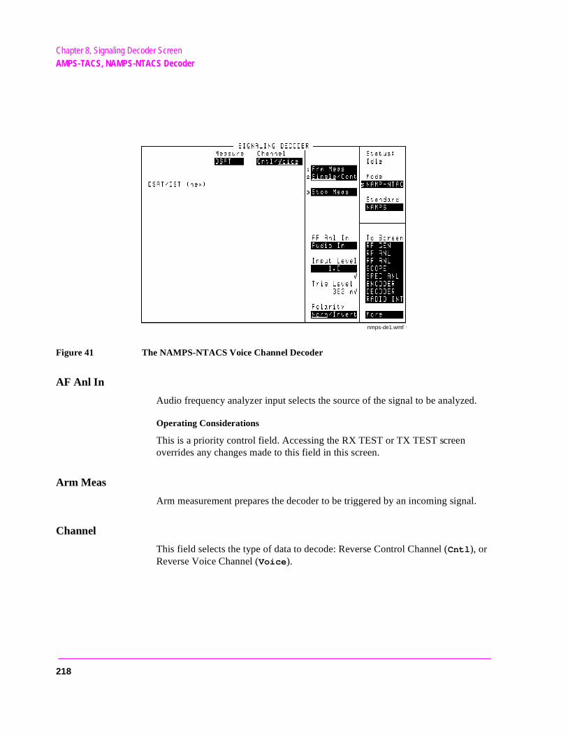
Chapter 8, Signaling Decoder ScreenAMPS-TACS, NAMPS-NTACS Decoder
Figure 41 The NAMPS-NTACS Voice Channel Decoder
AF Anl In
Audio frequency analyzer input selects the source of the signal to be analyzed.
Operating Considerations
This is a priority control field. Accessing the RX TEST or TX TEST screen overrides any changes made to this field in this screen.
Arm Meas
Arm measurement prepares the decoder to be triggered by an incoming signal.
Channel
This field selects the type of data to decode: Reverse Control Channel (Cntl), or Reverse Voice Channel (Voice).
nmps-de1.wmf
218
Chapter 8, Signaling Decoder ScreenAMPS-TACS, NAMPS-NTACS Decoder
l is
d /
Data (hex) (AMPS-TACS)
This display field lists the decoded data serially as it is received. This field is labeled RECC Data (hex) for the NAMPS/NTACS mode, but performs the identical function.
Gate Time
This field specifies how long the decoder analyzes a signal after it has been triggered. The longer the gate time, the greater the number of bits analyzed.
Operating Considerations
If the gate time is too long, the decoder’s data buffer becomes full. A message is displayed instructing you to decrease the gate time.
This function is not used with the NAMPS/NTACS RVC decoder.
See Also
Arm Meas field description, on page 218Num of Bits field description, on page 220
Input Level
This field specifies the expected data signal level (after de- emphasis if used). Thehigher the level of signal expected by the analyzer, the higher the trigger leveset.
Operating Considerations
The unit-of-measure is determined by the AF Anl In setting.
The input level should be set high enough to prevent false triggering, but lowenough to allow triggering for valid signals. This you to set the input level well below the expected level.
Also, when using de-emphasis, the Input Level setting may need to be reducesignificantly to properly decode the incoming signal. De-Emphasis is enableddisabled using the De-Emphasis field on the AF ANALYZER screen.
See Also
Trig Level field description, on page 221
219
Chapter 8, Signaling Decoder ScreenAMPS-TACS, NAMPS-NTACS Decoder
Measure(NAMPS-NTACS: RVC)
This field selects the type of decoded data to display: DSAT or DST codes, Message data, or DTMF (Dual-Tone Multi-Frequency) tone data.
Num of Bits
This field lists the total number of bits displayed. This number is dependent on Data Rate of the signal being decoded, the Gate Time of the decoder, and the size of the decoder’s data buffer.
Operating Considerations
The buffer has a maximum capacity of:
• 1584 bits for decoding Reverse Voice Channel (RVC) data streams.
• 1583 bits for decoding Reverse Control Channel (RECC) data streams.
This measurement is not available for NAMPS-NTACS RVC decoding.
See Also
Gate Time field description, on page 219
Polarity
This setting is used to match the polarity of the encoded signal being analyzed.
Normal Operation. When this field is set to Norm, a logical high (1) is displayed when a positive peak in the received signal is detected. A negative peak displays a logical low (0).
Inverted Operation. When this field is set to Invert, a logical high (1) is displayed when a negative peak in the received signal is detected. A positive peak displays a logical low (0).
RECC Data (NAMPS-NTACS: RECC)
This display field lists the decoded data serially as it is received. This is the same information that the AMPS-TACS Data (hex) measurement displays.
220
Chapter 8, Signaling Decoder ScreenAMPS-TACS, NAMPS-NTACS Decoder
on a
n.
to
will e
Single/Cont
This field specifies how long you want the analyzer to decode incoming signals:
• Single tells the analyzer to display the information received during one Gate Time (or after one measurement for NAMPS-NTACS RVC data).
• Cont is used to automatically re-arm the analyzer and display the measurementscontinual basis until Single is selected.
Stop Meas
Selecting this field stops the analyzer when making single measurements.
Trig Level
The trigger level indicates the minimum signal level required to begin a measurement that has been “armed.” The level is adjusted by changing the Input
Level field’s setting.
The input level should be set high enough to prevent false triggering, but lowenough to allow triggering for valid signals. This may require you to set the input level well below the expected level.
Trigger Pattern (bin)
This field allows you to enter a specific bit pattern to filter displayed informatioThe decoder only displays the received data when this binary pattern is encountered immediately after triggering. This is helpful when you only wantdisplay messages containing very specific information.
The trigger pattern is entered as a sequence of ones, zeros, and dots. A dot cause the decoder to trigger for either a one or a zero in that bit position in threceived data stream.
Operating Considerations
This function is not available for decoding NAMPS-NTACS RVC information.
221
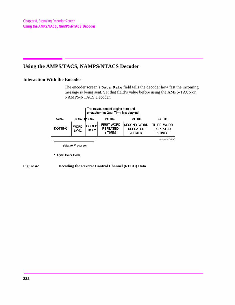
Chapter 8, Signaling Decoder ScreenUsing the AMPS/TACS, NAMPS/NTACS Decoder
r
Using the AMPS/TACS, NAMPS/NTACS Decoder
Interaction With the Encoder
The encoder screen’s Data Rate field tells the decoder how fast the incoming message is being sent. Set that field’s value before using the AMPS-TACS oNAMPS-NTACS Decoder.
Figure 42 Decoding the Reverse Control Channel (RECC) Data
amps-de2.wmf
222
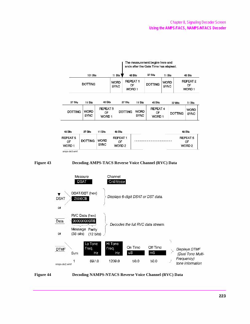
Chapter 8, Signaling Decoder ScreenUsing the AMPS/TACS, NAMPS/NTACS Decoder
Figure 43 Decoding AMPS-TACS Reverse Voice Channel (RVC) Data
Figure 44 Decoding NAMPS-NTACS Reverse Voice Channel (RVC) Data
amps-de3.wmf
nmps-de2.wmf
223
Chapter 8, Signaling Decoder ScreenUsing the AMPS/TACS, NAMPS/NTACS Decoder
t to
ital he
nc ces.
Interpreting Decoded Data
The following information refers to all Reverse Control Channel (RECC) measurements, and the AMPS-TACS Reverse Voice Channel (RVC) measurements. See the next section for information about NAMPS-NTACS RVC measurements.
After being armed, the measurement begins when the last bit of Word Sync has been received. All RECC measurements, and the AMPS-TACS RVC measurement, last for the period specified in the Gate Time field.
The received bits are displayed as hexadecimal (hex) characters. If the last bits received do not complete the last hex character, the received bits are used as the most significant bits in the character, and the remaining bit positions are filled with zeros.
For example; if the last bits received are “01”, two zeros are added to the righproduce the binary number 0100. The hexadecimal equivalent, 4, is displayed.
The first two hex characters of the RECC data displayed contain the 7-bit DigColor Code of the Seizure Precursor. The characters are right-justified so thefarthest bit to the left for the first hex character is always 0. The first word of tRECC message begins in the third hex character of the displayed data.
All bits of the RECC and RVC data streams received after the initial Word Syare displayed, including Parity and additional Dotting and Word Sync sequen
The decoder does not check for any errors in the received data stream.
224
Chapter 8, Signaling Decoder ScreenUsing the AMPS/TACS, NAMPS/NTACS Decoder
ived der d.
mea-arity ived:
. o-base sys-
NAMPS-NTACS Reverse Voice Channel Measurements
Three types of RVC information can be decoded; selected using the Measure field.
• DSAT displays the 6-digit DSAT (Digital Supervisory Audio Tone) or DST (Digital Signaling Tone) number, depending on the type of signal being received. If the recenumber is not one of the 14 standard combinations (7 DSAT or 7 DST), the decodisplays a constantly changing number until one of the standard values is detecte
• Data displays the 36 message bits and 12 parity bits of the RVC message. The surement begins when the last sync word bit is received, and ends after the last pbit is received. The measurement is re-triggered when the next sync word is recethere is no gate time function for this decoder mode.
• DTMF displays Dual-Tone Multi-Frequency tone pair frequencies and on/off timesThese are tones that may be used to trigger connected equipment after a mobile-tstation connection has been made (such as an answering machine or voice-mailtem).
225
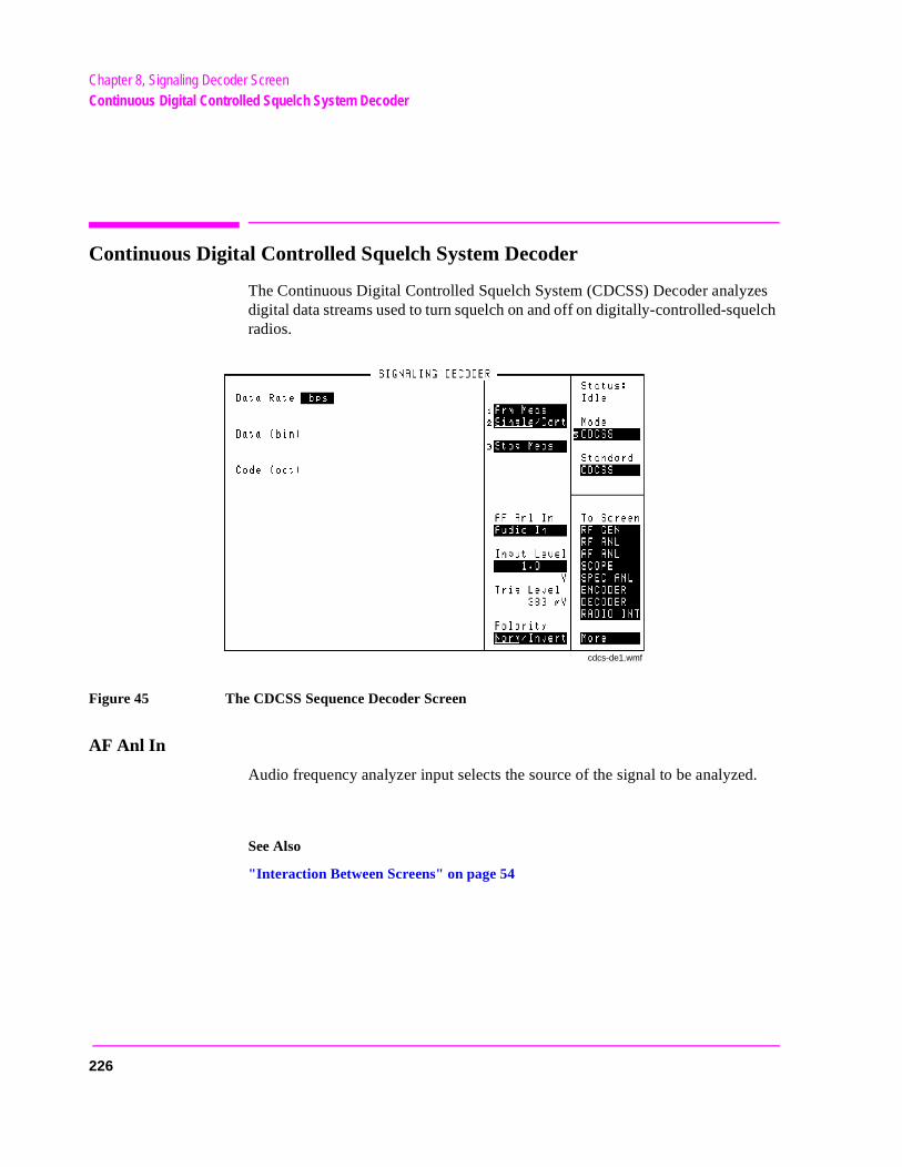
Chapter 8, Signaling Decoder ScreenContinuous Digital Controlled Squelch System Decoder
Continuous Digital Controlled Squelch System Decoder
The Continuous Digital Controlled Squelch System (CDCSS) Decoder analyzes digital data streams used to turn squelch on and off on digitally-controlled-squelch radios.
Figure 45 The CDCSS Sequence Decoder Screen
AF Anl In
Audio frequency analyzer input selects the source of the signal to be analyzed.
See Also
"Interaction Between Screens" on page 54
cdcs-de1.wmf
226
Chapter 8, Signaling Decoder ScreenContinuous Digital Controlled Squelch System Decoder
ling
t er.
Arm Meas
Arm measurement prepares the decoder to be triggered by an incoming signal when Single is selected.
Code (oct)
This field displays all of the code word combinations from the received data stream.
The top entry in this column is always 1 of the 83 standard (primary) industry codes or NPC (No Primary Code). All other possible code combinations are listed in numerical order after this entry.
If a Turn-Off Code (TOC) is measured for a full sampling period, TOC is displayed with no other codes listed.
Data (bin)
This measurement field displays a 23-bit segment of the data stream being received.
After 23 bits have been received, the decoder shifts the bit sequence 23 times until all possible bit patterns have been analyzed. Any possible code words are displayed in the Codes (oct) column. Even if no code words are found, this field will still display the bit sequence that was received.
Operating Considerations
This field is blank if the only signal received during the decoder’s latest sampperiod is a turn-off-code.
The final bit pattern displayed will not necessarily match any of the displayedcodes, since the bits are shifted 23 times during decoding.
Data Rate
This measurement field displays the data rate in bits-per-second for the datastream being received.
Operating Considerations
For accurate measurements, the Data Rate for the CDCSS encoder should be seto the expected data rate for the signal being analyzed by the CDCSS decod
227
Chapter 8, Signaling Decoder ScreenContinuous Digital Controlled Squelch System Decoder
g
Input Level
This field specifies the signal level that you input (after de-emphasis if used). The higher the level of signal expected by the analyzer, the higher the trigger level is set.
Operating Considerations
The unit-of-measure is determined by the AF Anl In setting.
The input level should be set high enough to prevent false triggering, but low enough to detect all valid zero-crossings of the incoming signal.
When using de-emphasis, the Input Level setting may need to be reduced significantly to properly decode the incoming signal. De-emphasis is enabled/disabled using the De-Emphasis field on the AF ANALYZER screen.
See Also
Trig Level field description, on page 229
Polarity
This field is used to match the polarity of the encoded signal being analyzed.
Normal Operation. When this field is set to Norm, a logical high (1) is displayed when a positive peak in the received signal is detected. A negative peak displays a logical low (0).
Inverted Operation. When this field is set to Invert, a logical low (0) is displayed when a positive peak in the received signal is detected. A negative peak displays a logical high (1).
Operating Considerations
Inverting amplifiers used in transmitters, receivers, and repeaters can cause an inversion of the modulating digital data. If the decoded signal does not display the expected results, change this field’s setting to see if the signal may be gettininverted before being decoded.
228

Chapter 8, Signaling Decoder ScreenContinuous Digital Controlled Squelch System Decoder
on a
Single/Cont
This field specifies how you want the analyzer to be armed:
• Single is used to analyze and display the decoded information once each time Arm Meas is selected.
• Cont is used to automatically re-arm the analyzer and display the measurementscontinual basis until Single is selected.
Stop Meas
Selecting this field stops the analyzer when making a single measurement.
Trig Level
The trigger level indicates the minimum signal level required to begin a measurement that has been “armed”. The level is adjusted by changing the Input Level field’s setting.
229
Chapter 8, Signaling Decoder ScreenUsing the CDCSS Decoder
Using the CDCSS Decoder
AF Analyzer Settings
For proper CDCSS decoder operation, make the following AF ANALYZER screen settings:
• Filter 1 to <20Hz HPF (Required)
• Filter 2 to 3kHz LPF (Recommended)
• Settling to Slow (Recommended)
Interpreting Decoded Data
Because CDCSS uses a continuously-repeating data stream, and there is no framing information to tell the receiver when the code word is going to be sent, the decoded data can result in several possible code combinations. This is why more than one code word may be listed in the Codes (oct) column after decoding.
230
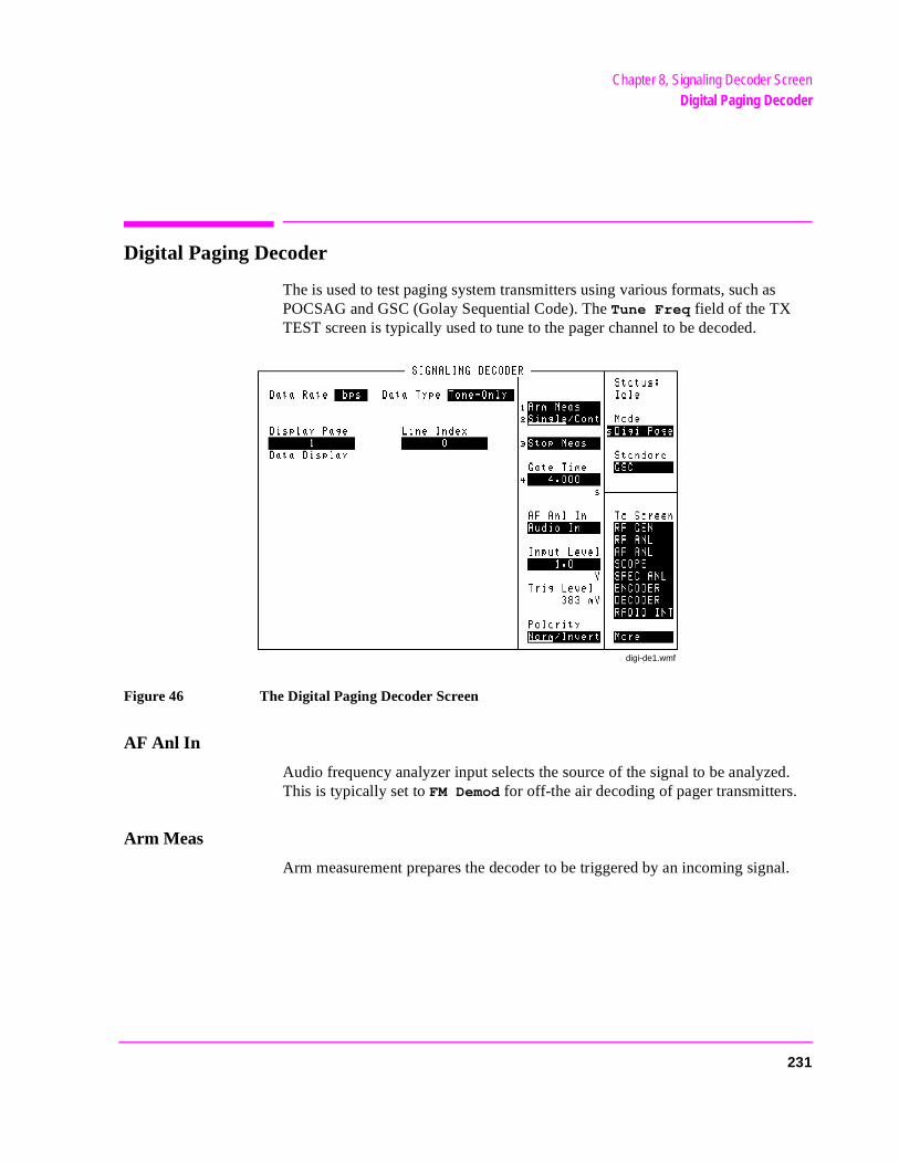
Chapter 8, Signaling Decoder ScreenDigital Paging Decoder
Digital Paging Decoder
The is used to test paging system transmitters using various formats, such as POCSAG and GSC (Golay Sequential Code). The Tune Freq field of the TX TEST screen is typically used to tune to the pager channel to be decoded.
Figure 46 The Digital Paging Decoder Screen
AF Anl In
Audio frequency analyzer input selects the source of the signal to be analyzed. This is typically set to FM Demod for off-the air decoding of pager transmitters.
Arm Meas
Arm measurement prepares the decoder to be triggered by an incoming signal.
digi-de1.wmf
231
Chapter 8, Signaling Decoder ScreenDigital Paging Decoder
ting.
ge of the
Data Display
This field displays up to three different decoded parameters after a message has been analyzed:
Pager code - the unique pager code number or address.
Function - number representing one of the four types of signals that can be sent.
Pager data - information sent as a numeric or alpha-numeric message. This parameter is not displayed when tone-only formats are decoded.
Data Rate
This display field lists the data rate of the received signal in bits-per-second (bps).
Operating Considerations
This measurement relies on the digital paging encoder screen’s data rate setSet the encoder’s Data Rate field to the expected incoming data rate for accurate measurements.
See Also
Data Rate field description, on page 320
Display Page
This field is used to select a specific page of decoded data. More than one padecoded data may be available when a batch of messages is received duringspecified gate time. The Number of Pages field indicates how many pages weredecoded.
232
Chapter 8, Signaling Decoder ScreenDigital Paging Decoder
Gate Time
This field specifies how long the decoder analyzes a signal after it has been triggered. Up to 65 seconds of gate time can be specified. The minimum gate time should be set long enough to allow the preamble and all necessary data bits to be captured.
If too much data is decoded during the gate time, the decoder buffer will overflow (an error message is displayed when this happens). Decrease the gate time if this error is displayed.
Input Level
Enter the expected data signal level in this field. The higher the level of signal expected by the analyzer, the higher the trigger level is set.
Operating Considerations
The unit-of-measure is determined by the AF Anl In setting.
The input level should be set high enough to prevent false triggering, but low enough to allow triggering for valid signals (typically about 3 kHz).
De-emphasis should not be used with this signaling format. Access the AF ANALYZER screen and set the De-Emphasis field setting to Off.
See Also
Trig Level field description, on page 234
Number of Pages
See the Display Page field description, on page 232
233
Chapter 8, Signaling Decoder ScreenDigital Paging Decoder
e.
on a rit-
Polarity
This setting is used to match the polarity of the encoded signal being analyzed.
Normal Operation. When this field is set to Norm, a logical high (1) is displayed when a positive peak in the received signal is detected. A negative peak displays a logical low (0).
Inverted Operation. When this field is set to Invert, a logical high (1) is displayed when a negative peak in the received signal is detected. A positive peak displays a logical low (0).
Single/Cont
This field specifies how long you want the analyzer to decode incoming signals:
• Single tells the analyzer to display the information received during one gate timMeasurements are displayed until Arm Meas is selected again.
• Cont is used to automatically re-arm the analyzer and display new measurementscontinual basis until Single is selected. Previous measurement results are over-wten by subsequent measurements.
Stop Meas
Selecting this field stops the analyzer when making single measurements.
Trig Level
The trigger level indicates the minimum signal level required to begin a measurement that has been “armed.” The level is adjusted by changing the Input
Level field setting.
234
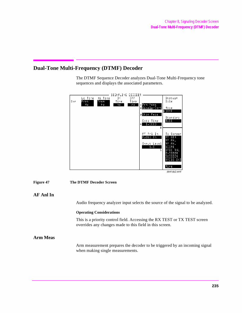
Chapter 8, Signaling Decoder ScreenDual-Tone Multi-Frequency (DTMF) Decoder
Dual-Tone Multi-Frequency (DTMF) Decoder
The DTMF Sequence Decoder analyzes Dual-Tone Multi-Frequency tone sequences and displays the associated parameters.
Figure 47 The DTMF Decoder Screen
AF Anl In
Audio frequency analyzer input selects the source of the signal to be analyzed.
Operating Considerations
This is a priority control field. Accessing the RX TEST or TX TEST screen overrides any changes made to this field in this screen.
Arm Meas
Arm measurement prepares the decoder to be triggered by an incoming signal when making single measurements.
dtmf-de2.wmf
235
Chapter 8, Signaling Decoder ScreenDual-Tone Multi-Frequency (DTMF) Decoder
Gate Time
This field specifies how long the decoder analyzes a signal after it has been triggered.
Hi Tone
This for the high frequency tone in each tone pair. The measurement type is selected by selecting the Freq field to display a list of measurement choices.
Operating Considerations
Frequency error is calculated by comparing the DTMF Encoder’s frequency settings for each tone pair with the decoded frequencies.
See Also
"Using the DTMF Decoder" on page 240
236
Chapter 8, Signaling Decoder ScreenDual-Tone Multi-Frequency (DTMF) Decoder
Input Level
This field specifies the signal level that you input (after de-emphasis if used). The higher the level of signal expected by the analyzer, the higher the trigger level is set.
Operating Considerations
The unit-of-measure is determined by the AF Anl In setting.
The input level should be set high enough to prevent false triggering, but low enough to allow triggering for fluctuating signal levels.
De-emphasis Effects
De-emphasis is a single-pole, low-pass filter with a 212.2 Hz corner frequency. It is enabled/disabled using the De-Emphasis field on the AF ANALYZER screen. (Refer to Figure 12, "AF ANALYZER Functional Block Diagram," on page 96.) The Input Level is the expected level at the output of the de-emphasis network.
Assuming a mean DTMF frequency of approximately 1 kHz, decoding with de-emphasis on (set to 750 µs) requires the input level to be set to 212/1000 = 0.212 times the peak deviation, or about 1/5 the incoming level of the tone.
Examples of Input Level Settings
Example 1
Peak deviation 3 kHz, De-emphasis off. Set the input level to 3 kHz.
Example 2
Peak deviation 3 kHz, De-emphasis 750 ms. Set the input level to 3×0.212 =636 Hz
237
Chapter 8, Signaling Decoder ScreenDual-Tone Multi-Frequency (DTMF) Decoder
r to
on a
Lo Tone
This measurement field lists the frequency or frequency error for the low frequency tone in each tone pair. The measurement type is selected by selecting the Freq field to display a list of measurement choices.
Operating Considerations
Frequency error is calculated by comparing the DTMF Encoder’s frequency settings for each tone pair with the decoded frequencies.
See Also
"Using the DTMF Decoder" on page 240
Off Time
This measurement column lists the length of time each tone pair was “off” priothe next tone being received.
On Time
This measurement column lists the length of time each tone pair was “on.”
Single/Cont
This field specifies how you want the analyzer to be armed:
• Single is used to analyze and display the decoded information once each time Arm Meas is selected.
• Cont is used to automatically re-arm the analyzer and display the measurementscontinual basis until Single is selected.
238
Chapter 8, Signaling Decoder ScreenDual-Tone Multi-Frequency (DTMF) Decoder
or ted in
pair.
Stop Meas
Selecting this field stops the analyzer when making single measurements.
Sym
The symbol column corresponds to the DTMF Encoder’s symbols assigned feach tone pair. As each tone pair is analyzed, the corresponding symbol is listhis column.
Operating Considerations
The symbol assigned is based on the closest symbol frequencies to that tone
239
Chapter 8, Signaling Decoder ScreenUsing the DTMF Decoder
Using the DTMF Decoder
Measurement Limits
Lo Tone: 680 - 960 Hz Hi Tone: 1190 - 1660 Hz
Actual limits are typically slightly wider than this. However, the crossover point between Hi and Lo tone decoding is approximately 1.1 kHz. If incoming tones approach this point, unreliable measurements may be displayed (frequency measurement errors and spurious off times).
240
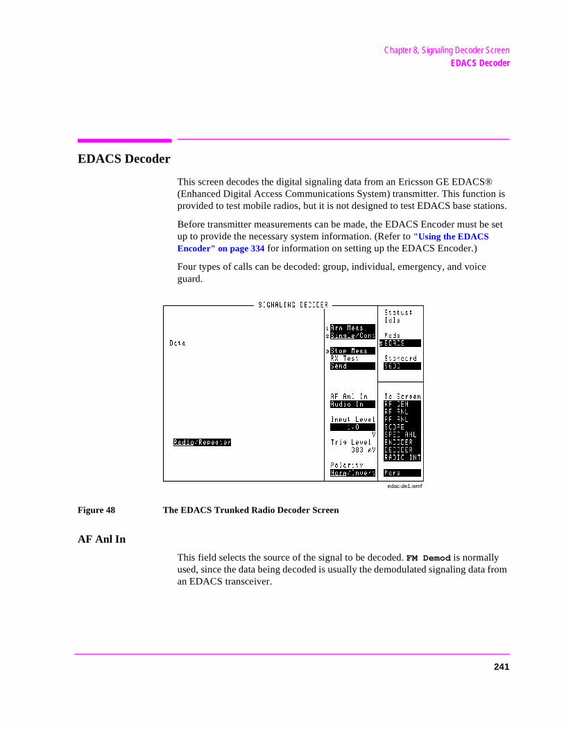
Chapter 8, Signaling Decoder ScreenEDACS Decoder
n is ions.
e set
from
EDACS Decoder
This screen decodes the digital signaling data from an Ericsson GE EDACS®(Enhanced Digital Access Communications System) transmitter. This functioprovided to test mobile radios, but it is not designed to test EDACS base stat
Before transmitter measurements can be made, the EDACS Encoder must bup to provide the necessary system information. (Refer to "Using the EDACS Encoder" on page 334 for information on setting up the EDACS Encoder.)
Four types of calls can be decoded: group, individual, emergency, and voiceguard.
Figure 48 The EDACS Trunked Radio Decoder Screen
AF Anl In
This field selects the source of the signal to be decoded. FM Demod is normally used, since the data being decoded is usually the demodulated signaling dataan EDACS transceiver.
edac-de1.wmf
241
Chapter 8, Signaling Decoder ScreenEDACS Decoder
Arm Meas
Select this field to prepare the decoder to be triggered by transmitted signaling data. When selected, the Status: field indicates Armed.
Data
This area displays the decoded call request signaling data from your transmitter. The type of data displayed depends on the Radio/Repeater setting and the type of message decoded.
Input Level
This field is used to set the trigger level for the decoder. The displayed Trig Level changes as the Input Level is adjusted. This field is normally set to 1 kHz for EDACS decoding (assuming the AF Anl In field is set to FM Demod).
Operating Considerations
The units displayed (kHz, %, V) depends on the AF Anl In setting.
Polarity
This field is used to match the polarity of the data to be decoded. This field is usually set to Norm.
See Also
Polarity field description, on page 331
242
Chapter 8, Signaling Decoder ScreenEDACS Decoder
coder
. It is
Radio/Repeater
This field specifies whether the decoder will trigger on the received sync word of a mobile signal (Radio), or on the sync word from a repeater (Repeater). It also specifies how the received data will be interpreted.
The repeater function is not fully implemented at this time to provide base station decoding.
RX Test
When Send is selected, the Control Channel Site ID message is output at the RX Frequency specified in the Control Channel settings on the EDACS Encoder screen.
Single/Cont
This field specifies how you want to arm the decoder.
• Single requires you to manually arm the decoder (using the Arm Meas field) before each measurement is made.
• Cont automatically arms the decoder to make a measurement, and re-arms the deafter a measurement is made.
Operating Considerations
To dis-arm the decoder in single mode, select the Stop Meas field. The Stop Meas function is disabled when Cont is selected.
Standard
The encoder’s Data Rate field must be set to the data rate expected from theradio or the repeater being decoded. This is best done by selecting the corresponding standard on the encoder’s screen.
See Also
Standard field description, on page 332
Stop Meas
This field is used to dis-arm the decoder when making single measurementsnot used when making continuous (Cont) measurements.
243

Chapter 8, Signaling Decoder ScreenUsing the EDACS Decoder
IN/
Using the EDACS Decoder
EDACS Transmitter Testing
When the mobile is turned on, it automatically tunes to its pre-programmed control channel frequency. The Test Set generates the control channel signal using the RF Generator and the Control Channel fields of the EDACS Encoder.
When the mobile is receiving the control channel, the transmitter can be keyed to send a call request message to go to a working channel. (The working channel settings are specified in the EDACS Encoder.)
After the mobile starts transmitting, the EDACS Decoder displays the decoded signaling data. You can then access the DUPLEX TEST screen to make modulation and RF carrier measurements.
Transmitter Test Procedure
This procedure establishes a control channel connection between the Test Set and your mobile. After the mobile locks to the control channel, the decoder is armed and the mobile’s transmitter is keyed to make measurements.
NOTE: Each EDACS radio is pre-programmed to access a specific control channel and one or moreworking channels. Other mobile and system identification information is also programmedinto the radio. You cannot test an EDACS mobile without first entering these values into theEDACS Encoder screen.
CAUTION: Before testing your transmitter, read the MAX PWR limit printed under the Test Set’s RFOUT port. Exceeding this limit could damage your Test Set.
Preset the Test Set
Press the PRESET key on the Test Set to set all controls to a known state and display the RX TEST screen.
Connect the Mobile to the Test Set
Connect the antenna port of the mobile to the RF IN/OUT port of the Test Set.
244
Chapter 8, Signaling Decoder ScreenUsing the EDACS Decoder
e.
e.
.
g
g
t-
le,
Define the Control Channel Settings1. Turn AF Generator 1 off by positioning the cursor in front of the 3.00 value of the
AFGen1 To field and pressing the ON/OFF key. 2. Select ENCODER from the To Screen menu. 3. Select the EDACS Mode to display the EDACS Encoder. 4. Select the Data Rate using the Standard field. (4800 or 9600 bps) 5. Enter the Control Channel settings.
• The Number is your system’s control channel number.
• The RX Frequency is the control channel’s receive frequency for your mobil
• The TX Frequency is the control channel’s transmit frequency for your mobil
6. Enter the Working Channel settings.
• The Number is the working channel number you want the mobile to be sent to
• The RX Frequency is the mobile’s receive frequency for the selected workinchannel.
• The TX Frequency is the mobile’s transmit frequency for the selected workinchannel.
7. Enter the Logical ID number. 8. Enter the Group ID number. 9. Enter the Site ID number.
Prepare the Decoder for Transmitter Measurements1. Turn the SQUELCH control on the Test Set fully clockwise. 2. Select DECODER from the To Screen menu to access the EDACS Decoder. 3. Set the AF Anl In field to FM Demod to demodulate the signal from your transmi
ter. 4. Set the Input Level field to about one third of the expected deviation. (For examp
if your transmitter’s deviation is 3 kHz, set the Input Level to about 1 kHz.) 5. Select the Arm Meas field to prepare the decoder. The Status: field should indicate
Armed. 6. Select the Send field (under RX Test). This outputs the control channel information
specified in the EDACS Encoder.
The mobile should indicate that it is receiving the control channel data.
245
Chapter 8, Signaling Decoder ScreenUsing the EDACS Decoder
pe, er
ST
as se.
Make Basic Transmitter Measurements
1. Key the mobile’s transmitter and verify that its transmit indicator is on. The call tyGroup ID, and Logical ID information transmitted by your mobile is displayed undthe Data field.
2. With the transmitter still keyed, press the DUPLEX key to access the DUPLEX TEscreen. TX Frequency and TX Power are displayed.
Making Other Transmitter Measurements
By connecting Audio Frequency Generator 1 (AFGen 1) to your transmitter’s microphone input, you can make calibrated modulation measurements; suchmicrophone sensitivity, modulation limiting, and transmitter frequency respon
1. Connect the AUDIO OUT port of the Test Set to your mobile’s microphone input.
2. Access the DUPLEX TEST screen.
3. Set the upper part of the AFGen1 To field to Audio Out.
4. Use the lower part of the AFGen1 To field to adjust the output level into the micro-phone line.
5. Use the AFGen1 Freq field to adjust the audio generator’s frequency.
246
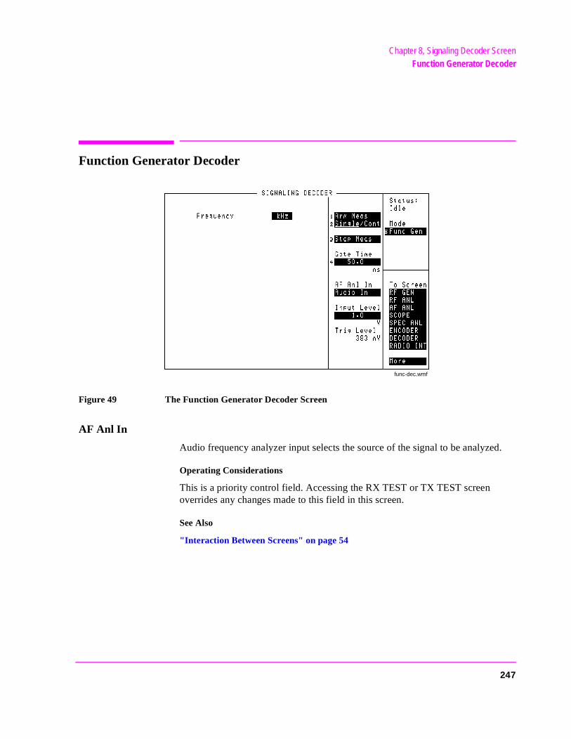
Chapter 8, Signaling Decoder ScreenFunction Generator Decoder
Function Generator Decoder
Figure 49 The Function Generator Decoder Screen
AF Anl In
Audio frequency analyzer input selects the source of the signal to be analyzed.
Operating Considerations
This is a priority control field. Accessing the RX TEST or TX TEST screen overrides any changes made to this field in this screen.
See Also
"Interaction Between Screens" on page 54
func-dec.wmf
247
Chapter 8, Signaling Decoder ScreenFunction Generator Decoder
as
gger
’s
Arm Meas
Arm measurement prepares the decoder to be triggered by an incoming signal when making single measurements.
Frequency
This measurement displays the decoded signal’s frequency.
Gate Time
This field specifies the minimum time the decoder analyzes a signal after it hbeen triggered.
Input Level
This field specifies the signal level that you input (after de-emphasis if it is turned on). The higher the level of signal expected by the analyzer, the higher the trilevel is set.
Operating Considerations
The unit-of-measure is determined by the AF Anl In setting.
The input level should be set high enough to prevent false triggering, but lowenough to allow triggering for fluctuating signal levels.
If de-emphasis is used (by setting the AF Analyzer’s De-Emphasis field to 750 µs), the Input Level should be set to about 1/5 of the measured signallevel. For example, a 1 kHz, 1 Vpeak sinewave into the AF Analyzer’s input requires an Input Level of approximately 0.212 V to trigger correctly.
See Also
Trig Level field description, on page 254
248
Chapter 8, Signaling Decoder ScreenFunction Generator Decoder
on a
Stop Meas
Selecting this field stops the analyzer when making single measurements.
Single/Cont
This field specifies how you want the analyzer to be armed:
• Single is used to analyze and display the decoded information once each timeArm Meas is selected.
• Cont is used to automatically re-arm the analyzer and display the measurementscontinual basis until Single is selected.
Trig Level
The trigger level indicates the minimum signal level required to begin a measurement that has been “armed”. The level is adjusted by changing the Input Level field setting.
249

Chapter 8, Signaling Decoder ScreenUsing the Function Generator Decoder
Using the Function Generator Decoder
Decoding Considerations
Frequency measurements are affected by the Filter1, Filter2, Settling, and De-Emphasis settings in the AF ANALYZER screen.
Four dashes (- - - -) are displayed if the incoming signal is out of range, or if the Gate Time is too long for the frequency being measured.
250
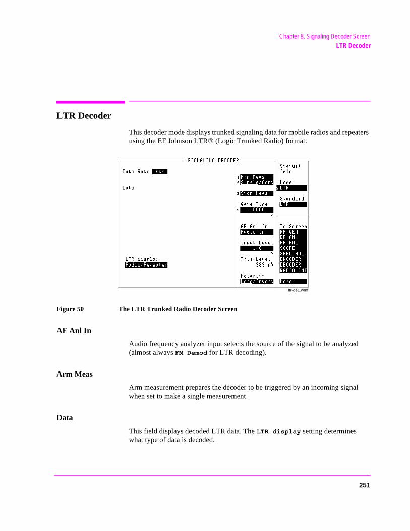
Chapter 8, Signaling Decoder ScreenLTR Decoder
d
al
LTR Decoder
This decoder mode displays trunked signaling data for mobile radios and repeaters using the EF Johnson LTR® (Logic Trunked Radio) format.
Figure 50 The LTR Trunked Radio Decoder Screen
AF Anl In
Audio frequency analyzer input selects the source of the signal to be analyze(almost always FM Demod for LTR decoding).
Arm Meas
Arm measurement prepares the decoder to be triggered by an incoming signwhen set to make a single measurement.
Data
This field displays decoded LTR data. The LTR display setting determines what type of data is decoded.
Itr-de1.wmf
251
Chapter 8, Signaling Decoder ScreenLTR Decoder
the
). r
Data Rate
This display field lists the data rate of the received signal.
Operating Considerations
This measurement relies on the LTR Encoder screen’s data rate setting. Setencoder’s Data Rate field to the expected incoming data rate for accurate measurements (typically 297.6 bps).
Gate Time
This field specifies how long the decoder analyzes a signal after it has been triggered.
Input Level
Enter the expected data signal level in this field (typically 1 kHz for LTR dataThe higher the level of signal expected by the analyzer, the higher the TriggeLevel is set.
Operating Considerations
The unit-of-measure is determined by the AF Anl In setting (kHz when the input is FM Demod).
The input level should be set high enough to prevent false triggering, but lowenough to allow triggering for valid signals.
See Also
Trig Level field description, on page 254
252
Chapter 8, Signaling Decoder ScreenLTR Decoder
ht
rom uring
ent it.
LTR Display• Radio - displays the mobile’s transmitted trunking data. An example display mig
look like this:
Area : 0Goto : 2Home : 2ID : 128Free : 31
• Repeater - lists the 20 possible repeater numbers in an LTR system. The data fthe monitored repeater is displayed. If multiple radios try to access the repeater ddecoding, the data sent to those radios by that repeater is also displayed.
The data is displayed as a series of digits next to the number of the repeater that sFor example, a decoded message with a Goto number of 02 may look like this:
01: 02: 002021280603: 04:04: 05:~ ~
This is interpreted as follows:
02: 0 02 02 128 06Repeater Area Goto Home ID Free
Polarity
This setting is used to match the polarity of the encoded signal being analyzed.
Normal Operation. When this field is set to Norm, a logical high (1) is displayed when a positive peak in the received signal is detected. A negative peak displays a logical low (0).
Inverted Operation. When this field is set to Invert, a logical high (1) is displayed when a negative peak in the received signal is detected. A positive peak displays a logical low (0).
253
Chapter 8, Signaling Decoder ScreenLTR Decoder
ate
on a
Single/Cont
This field specifies how long you want the analyzer to decode incoming signals:
• Single tells the analyzer to display valid LTR information received during one gtime.
• Cont is used to automatically re-arm the analyzer and display the measurementscontinual basis until Single is selected.
Stop Meas
Selecting this field stops the analyzer when making single measurements.
Trig Level
The trigger level indicates the minimum signal level required to begin a measurement that has been “armed.” The level is adjusted by changing the Input Level field setting.
254
Chapter 8, Signaling Decoder ScreenUsing the LTR Decoder
Using the LTR Decoder
Decoding Mobile Radio Signaling Data
A transmit channel must be established before a mobile radio is tested (otherwise the transmitter will attempt to transmit but time-out and de-key automatically). A procedure for establishing a trunked transmit channel is provided in "Using the LTR Encoder" on page 346.
After establishing a trunked transmit channel, keep the transmitter keyed and perform the following steps.
1. Access the DECODER screen, and select LTR for the Mode.
2. Set the LTR display field to Radio.
3. Set the Single/Cont field to Single.
4. Set the AF Anl In field to FM Demod.
5. Set the Input Level to 1 kHz.
6. Select Arm Meas to prepare the decoder for triggering. The transmitted data should be displayed after being computed.
An End of Data reached during decode. message may be displayed at the top of the screen during decoding. Four conditions usually cause this message to be displayed:
• The Gate Time is too short to decode all the data. Increase this setting.
• The Input Level is set too low or too high. Change the level.
• The trunking data is inverted. Select Invert in the Polarity field.
• The LTR radio is not transmitting. Re-establish a transmit channel.
255
Chapter 8, Signaling Decoder ScreenUsing the LTR Decoder
;
ed.
a.
ed
,
Decoding Repeater Signaling Data
Press the PRESET key.
1. Access the DUPLEX TEST screen.
2. Set the Tune Mode to Manual.
3. Enter your repeater’s transmit frequency in the Tune Freq field.
4. Select the Input Port (RF IN/OUT for direct transmitter-to-Test Set connectionsAnt (ANT IN) for off-the-air measurements).
5. Attach an antenna to the Test Set if you are making off-the-air measurements.
6. Access the DECODER and select the LTR mode.
7. Set the LTR display field to Repeater.
8. Select the triggering mode.
• Select Single to decode and display only the first valid transmitter data receivThe decoder must be re-armed before another measurement can be made.
• Select Cont to continuously monitor a repeater and display its transmitted dat
9. Set the AF Anl In field to FM Demod.
10. Set the Input Level to 1 kHz.
11. Select Arm Meas if you are using single triggering. The transmitted data is displayafter computing is displayed in the Status field.
If no decoded data is displayed
• The repeater may not be transmitting.
• The RF signal may be too low for off-the-air measurements. Use a better antennaor set the RF ANALYZER screen’s Sensitivity field to High.
• The Gate Time may be too short. Increase the value.
• The received data may be inverted. Set the Polarity field to Invert.
• The trigger level may be too low or too high. Change the Input Level setting.
256
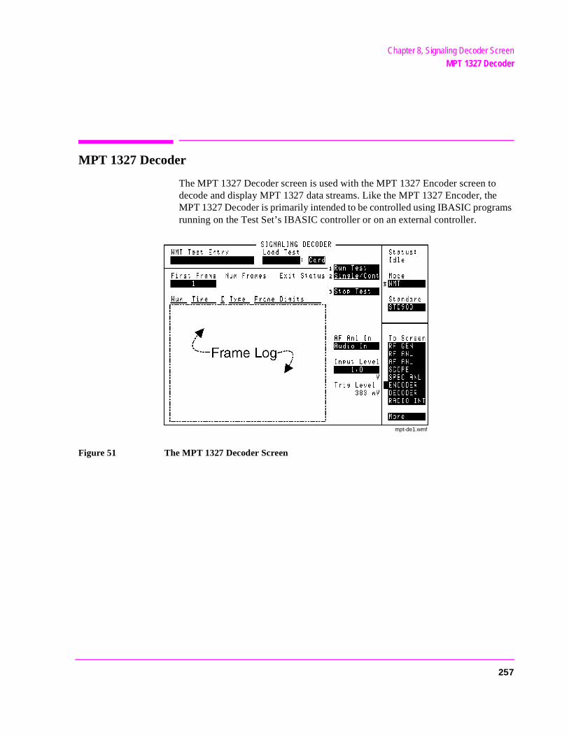
Chapter 8, Signaling Decoder ScreenMPT 1327 Decoder
MPT 1327 Decoder
The MPT 1327 Decoder screen is used with the MPT 1327 Encoder screen to decode and display MPT 1327 data streams. Like the MPT 1327 Encoder, the MPT 1327 Decoder is primarily intended to be controlled using IBASIC programs running on the Test Set’s IBASIC controller or on an external controller.
Figure 51 The MPT 1327 Decoder Screen
mpt-de1.wmf
257
Chapter 8, Signaling Decoder ScreenMPT 1327 Decoder
Manually Decoding MPT 1327 Signals
To manually test MPT 1327 radios using this decoder, you must first set up the MPT 1327 Encoder to provide the necessary protocol to get the radio up on the correct channel. This requires a thorough knowledge of the MPT 1327 Encoder operation, including using the undisplayed controls accessed using IBASIC commands.
For these reasons, the following information generally assumes you are operating the decoder under IBASIC control.
Decoder Triggering
For MPT 1327 signaling detection, the decoder should be configured for repetitive retriggering using the HP-IB command:
TRIGger:MODE:RETRigger REPetitive
When the decoder is armed it is triggered whenever it receives the synchronization sequence appropriate to the test mode (selected on the MPT 1327 Encoder screen). Refer to table 6.
258
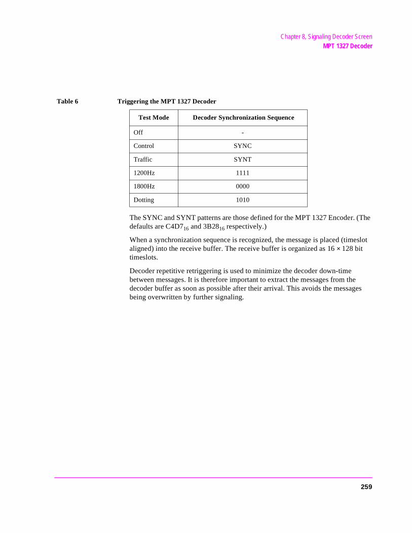
Chapter 8, Signaling Decoder ScreenMPT 1327 Decoder
The SYNC and SYNT patterns are those defined for the MPT 1327 Encoder. (The defaults are C4D716 and 3B2816 respectively.)
When a synchronization sequence is recognized, the message is placed (timeslot aligned) into the receive buffer. The receive buffer is organized as 16 × 128 bit timeslots.
Decoder repetitive retriggering is used to minimize the decoder down-time between messages. It is therefore important to extract the messages from the decoder buffer as soon as possible after their arrival. This avoids the messages being overwritten by further signaling.
Table 6 Triggering the MPT 1327 Decoder
Test Mode Decoder Synchronization Sequence
Off -
Control SYNC
Traffic SYNT
1200Hz 1111
1800Hz 0000
Dotting 1010
259
Chapter 8, Signaling Decoder ScreenMPT 1327 Decoder
aud rn.
rel-n:
mes-eived
Detecting and Querying Messages
IBASIC can be informed about the arrival of a message in the decoder buffer. To do this, configure the HP-IB status registers to cause a service request (SRQ) on the negative transition event of bit 12, “Decoder Result Available” in the Hardware Status Register #1.
For further information on the Hardware Status Register refer to the Programmer’s Guide.
The message is read from the decoder buffer by the command:
MEASure:DECoder:MPT1327:BUFFer?
This query returns a quoted string comprising the contents of one or more timeslots. The string is disassembled into mnemonic form. If more than one message is received, the individual messages are separated by semicolons. If a timeslot contains data codewords, it is disassembled into the DCW extension. Examples of this are:
• Simple RQS from RU. RQS 0,1,5,0
• Cleardown from RU sent in three consecutive timeslots. MAINT 0,1,283,3,0;MAINT 0,1,283,3,0;MAINT 0,1,283,3,0
• SAMIS response to AHYC giving PSTN digits for call. SAMIS 14391,83782;DCW #H080000000000,#H000000000000
There are two other measurements available on the decoder screen:
• The Signaling Data Rate. The signaling data rate measurement is the measured brate of the received message. It is most accurately measured on a “dotting” patte
• The Received Message Timing. This measures the timing of the received message ative to the timeslots in the forward control channel. It has two modes of operatio
•Slot timing mode. This works in the Control test mode only, it is disabled inall other modes. This is the default mode.
•The timing counter is reset at the end of every control channel timeslot. If a sage is received, the time from the most recent slot end, to the start of the recmessage’s preamble, is reported as the timing measurement result.
260

Chapter 8, Signaling Decoder ScreenMPT 1327 Decoder
was d re-t is ries
.
itted ans-
rans- pat-
ked. that
•In the slot timing mode it is not possible to determine whether the messagereturned in the “correct” timeslot. (For example, if it is a response that shoulturn in the timeslot immediately following the requesting forward message.) Ipossible to check that the timing offset from the forward channel slot boundais within specification.
•This mode is selected with the following HP-IB with the command:
•DECoder:MPT1327:TIME:MODE ’SLOT
• works in the Control and Traffic test modes, it is disabled in all other modes
•In Control mode the timing counter is reset at the end of each message transmfrom the control channel message buffer. It is not affected by the on-going trmission of the control channel filler pattern.
•In the Traffic mode the timing counter is reset at the end of each message tmitted from the traffic channel message buffer. There is no background fillertern.
•In the response timing mode both next slot and slot offset timing can be checThe received message must however, be solicited by a forward message sothe timer is reset and the measurement is meaningful.
•This mode is selected via the HP-IB with the command:
•DECoder:MPT1327:TIME:MODE ’RESPONSE’
261
Chapter 8, Signaling Decoder ScreenNMT Decoder
NMT Decoder
The NMT Encoder and Decoder work together to test Nordic Mobile Telephone equipment used in a number of countries using different NMT standards. As each standard is selected, the Test Set configures the encoder and decoder to create and measure the corresponding RF carrier and digital data structure.
The following terms are used throughout the NMT sections of the manual:
DUT - Device-Under-Test: The device being tested (MS, BS, or MTX).
Frames - Groups of digital information that comprise an NMT signal. (This manual as-sumes you understand the frame structure for the signals you need to create or analyze; any frame information provided is for reference purposes.)
MS - Mobile Station: The equipment used by a mobile subscriber.
BS - Base Station: The unit that provides the radio interface between one or more Mo-bile Stations and the Mobile Telephone Exchange.
MTX - Mobile Telephone Exchange: The unit that provides the interface between one or more Base Stations and the telephone network.
Standard - The set of frequency and data format standards used by different countries.
The NMT Decoder screen is used to load and run NMT test programs you create. The programs are used to transmit NMT-encoded signals to a device, and to evaluate received NMT signals.
262
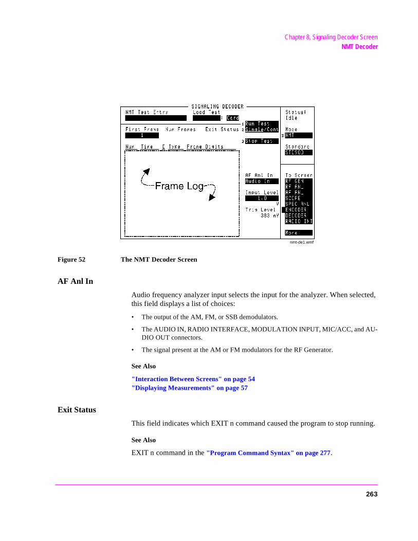
Chapter 8, Signaling Decoder ScreenNMT Decoder
Figure 52 The NMT Decoder Screen
AF Anl In
Audio frequency analyzer input selects the input for the analyzer. When selected, this field displays a list of choices:
• The output of the AM, FM, or SSB demodulators.
• The AUDIO IN, RADIO INTERFACE, MODULATION INPUT, MIC/ACC, and AU-DIO OUT connectors.
• The signal present at the AM or FM modulators for the RF Generator.
See Also
"Interaction Between Screens" on page 54"Displaying Measurements" on page 57
Exit Status
This field indicates which EXIT n command caused the program to stop running.
See Also
EXIT n command in the "Program Command Syntax" on page 277.
nmt-de1.wmf
263
Chapter 8, Signaling Decoder ScreenNMT Decoder
e
e
Frame Log
The Frame Log area lists the recorded frame information generated by the encoder and received by the decoder. Field descriptions for this area are listed together.
D
The Direction column tells if a frame was transmitted by the encoder (T), or received by the decoder (R).
Frame Digits
This column lists the information part of the recorded frames, displayed as hexadecimal digits.
Num
This column lists the reference numbers assigned to the recorded frames in the order they were transmitted and received.
Time
The times in this column indicate when each frame was transmitted or received after Run Test was selected. The times are listed in bit intervals that are dependent on the data rate set in the NMT Encoder.
For example, at a data rate of 1200 bps, one bit interval is equivalent to 0.833 ms (1/1200).
Type
This column lists the NMT standards frame type for each frame.
Operating Considerations
The received frame type is determined using the decoder’s Standard field setting, and the encoder’s DUT field setting. If these settings do not agree with thactual DUT and its standard, the received (R) frame types may not be correctly identified.
The transmitted frame type is determined by the Send f commands used in thNMT test program being executed.
264
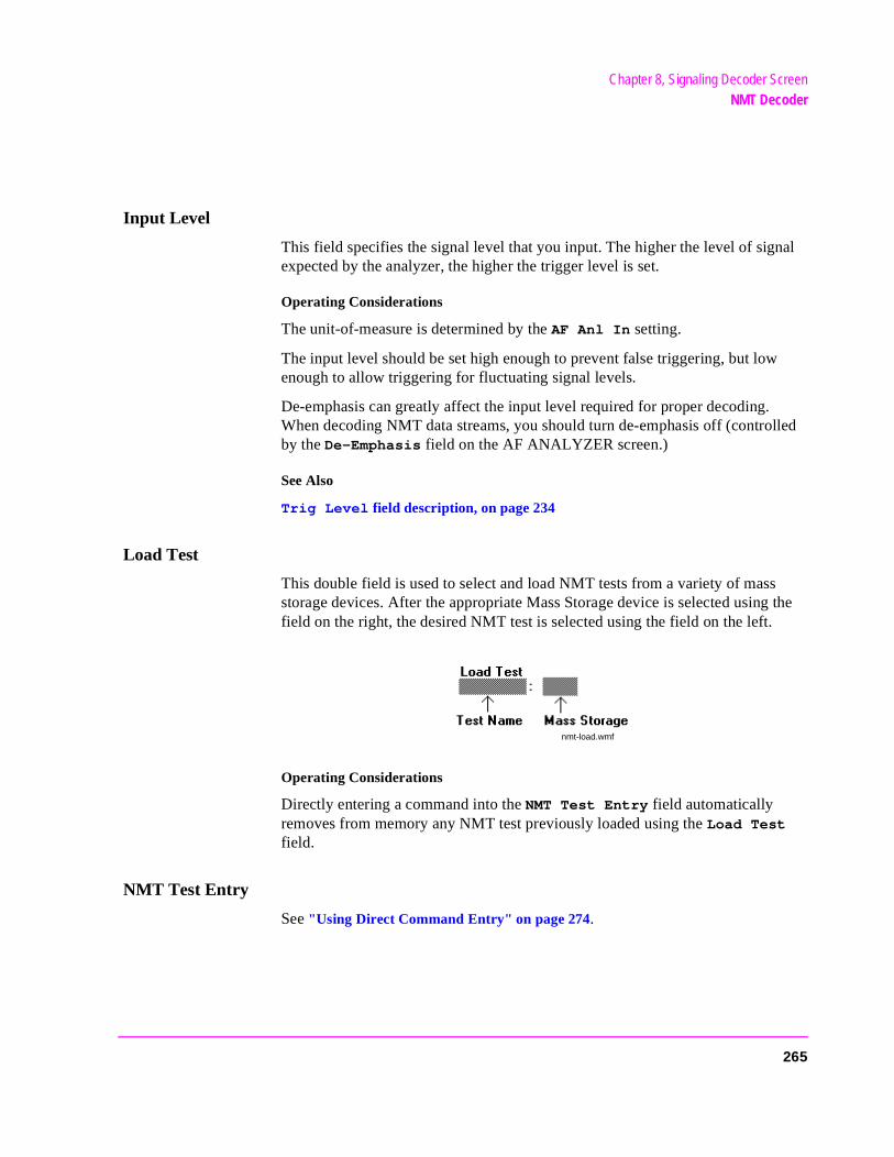
Chapter 8, Signaling Decoder ScreenNMT Decoder
Input Level
This field specifies the signal level that you input. The higher the level of signal expected by the analyzer, the higher the trigger level is set.
Operating Considerations
The unit-of-measure is determined by the AF Anl In setting.
The input level should be set high enough to prevent false triggering, but low enough to allow triggering for fluctuating signal levels.
De-emphasis can greatly affect the input level required for proper decoding. When decoding NMT data streams, you should turn de-emphasis off (controlled by the De-Emphasis field on the AF ANALYZER screen.)
See Also
Trig Level field description, on page 234
Load Test
This double field is used to select and load NMT tests from a variety of mass storage devices. After the appropriate Mass Storage device is selected using the field on the right, the desired NMT test is selected using the field on the left.
Operating Considerations
Directly entering a command into the NMT Test Entry field automatically removes from memory any NMT test previously loaded using the Load Test field.
NMT Test Entry
See "Using Direct Command Entry" on page 274.
nmt-load.wmf
265
Chapter 8, Signaling Decoder ScreenNMT Decoder
each
il
Run Test
Selecting this function executes (runs) the NMT test specified in the Load Test field or entered directly into the NMT Test Entry field.
Single/Cont
This field specifies how you want the test to be run:
• Single executes the NMT program and displays the decoded information once time Run Test is selected.
• Cont continually re-runs the program, and displays the decoded information, untSingle is selected.
Stop Test
Selecting this field interrupts the NMT test while running. If Cont is selected, the program automatically re-runs from the beginning.
Standard
This field specifies the NMT standard for the signal being decoded.
Operating Considerations
This setting alters the decoder’s function by specifying the expected frame structure and channel range for the incoming signal.
Trying to run a test with the wrong standard selected will result in incorrect decoded data, or will display an operating error message.
See Also
Trig Level field description, on page 221 "Standard Equivalents" on page 269
Trig Level
Trigger level indicates the minimum signal level required to begin a measurement. This level is adjusted by changing the Input Level field setting.
266
Chapter 8, Signaling Decoder ScreenUsing the NMT Decoder/Encoder
ion
Using the NMT Decoder/Encoder
General Encoder Operation The following are fields that are typically used for testing different types of NMT equipment.
Refer to the individual field descriptions for detailed information on each field’s functand operating parameters.
Testing Mobile Stations
These fields are typically used to test an MS:
• Calling Channel: Number and Power • Traffic Channel (Main): Number and Power • Traffic Channel (Alt): Number and Power • Traffic Area: Main and Alt • DUT • TCI (Tariff Class Information) • MSN (Mobile Subscriber Number) • Data Rate • Access Channel: Number and Power • Batt Save • Area # • Add Info • SIS Challenge
Testing A BS or MTX
These fields are typically used to test a BS or MTX:
• Mgmt/Maint • Meas Ch # • Phi Signal • Meas Field Strength • Password • BS Identity • Alarm Level High and Low • SIS Response
Fields Used with Different Standards
Fields in the upper part of the screen are used with all NMT standards. Fields in the lower part of the screen are only used with the STD900 standard.
267
Chapter 8, Signaling Decoder ScreenUsing the NMT Decoder/Encoder
es.
s.
e of hen
General Decoder Operation
The NMT Decoder screen has several uses:
• Entering NMT programming commands.
• Loading existing NMT tests from a variety of storage media.
• Running NMT tests.
• Decoding received NMT signals.
Operating Steps
Manual NMT radio tests generally follow four basic steps:
1. Write your test program to send encoded information and evaluate received fram2. Enter the necessary information into the various encoder and decoder fields. 3. Make the required Test Set AF Analyzer, RF Analyzer, and RF Generator setting4. Load and run your program from the decoder.
Changing Standards: Each NMT standard affects several operating parameters for thencoder and decoder screens; however, there are no visual changes to the contentseither screen when standards are changed. You must be aware of these changes wmanually testing radios using these screens. Refer to the Standard and Calling Channel Number field descriptions for expla-nations on the effects of these fields
268
Chapter 8, Signaling Decoder ScreenUsing the NMT Decoder/Encoder
sed
nd
Standard Equivalents
Only two standards are referred to in this section: STD450 and STD900. All other national standards are based on these two. If a field description says “only uwith the STD900 standard”, the field can also be used with other national standards listed under the STD900 equivalents below.
The following list identifies which national standards are based on STD450 aSTD900:
STD450 Equivalents• Austria • Benelux • Bulgaria • Cro-Slav (Croatia-Slovenia) • Hungary • Malaysia • Saudi 1 • Saudi 2 • Spain • Thailand • Turkey
STD900 Equivalents
• France (Uses the STD900 protocol at STD450 frequencies)
Manual Testing of NMT Radios
NMT signals contain complex groupings of digital data that vary in format and function, depending on a number of system operating needs.
To be able to test NMT radios using these screens, you must be familiar with the theory, applications, and specifications of the NMT systems. The large volume of information required to explain the NMT system is beyond the scope of this manual.
Documents explaining the structure and specifications for the different NMT standards should be obtained from the radio communications regulatory agency of the appropriate country.
269
Chapter 8, Signaling Decoder ScreenUsing the NMT Decoder/Encoder
Required Test Set Settings
The following Test Set settings should be made before using the NMT Encoder/Decoder screens. These settings assume the Test Set is in its preset state.
RF Generator Settings
AFGen1 To: Audio Out and Off
AFGen2 To: FM and 3.5 kHz
RF Analyzer Settings
Tune Mode: Manual
Input Atten: Hold and 0 dB
Squelch: Fixed
AF Analyzer Settings
AF Anl In: FM Demod
Filter 1: 300Hz HPF
Filter 2: 15kHz LPF
De-Emphasis: Off
Initial NMT Encoder Settings
Mode: NMT
DUT: MS (for testing Mobile Stations)
Initial NMT Decoder Settings
Input Level: 3.0 kHz
270
Chapter 8, Signaling Decoder ScreenUsing the NMT Decoder/Encoder
Special Frame Suffixes
Some frame designations include a suffix to identify specific encoder screen fields (such as TC2 for Alternate Traffic Channel) or to indicate special frame values affected (such as the S suffix that indicates Battery Save information; example - 1aS).
The following suffixes are appended to some frame designations:
AC = Access Channel
CC = Calling Channel
S = Battery Save
TA1 = Main Traffic Area
TA2 = Alternate Traffic Area
TC1 = Main Traffic Channel
TC2 = Alternate Traffic Channel
271
Chapter 8, Signaling Decoder ScreenCreating NMT Tests
ow
ese
ed.
mass
Creating NMT Tests
The NMT Encoder outputs signals using programs running in the NMT Decoder. This differs from the Test Set’s other signaling encoder functions that have a“send” function to directly output their signals (such as DTMF and Tone Sequence).
To use the NMT Encoder and Decoder functions, you must first understand htests are written.
Programming Overview
Special program commands are used by the Test Set to test NMT radios. Thcommands are used to send frames, perform simple branching and looping operations, change RF channels, and test received frame types.
The NMT Decoder has its own RAM to run programs. All NMT program commands must be entered into the decoder’s RAM before they can be executThis can be done directly by entering commands one at a time into the NMT Test
Entry field, or by loading a test program that has been created and saved onstorage.
NOTE: NMT Format: When storing NMT tests you have created, you must save them as ASCII filesusing the BASIC command SAVE (and use the GET command to retrieve them). Non-ASCIIfiles cannot be retrieved using the NMT Decoder screen’s Load Test field, and thereforecannot be run.
272
Chapter 8, Signaling Decoder ScreenCreating NMT Tests
Test
pro-
ro-
the
Creating NMT Tests
Tests can be created and saved using any of these methods:
• Writing programs on a connected external controller, downloading them into the Set’s IBASIC RAM, and then storing them on mass storage.
• Using the TESTS screen’s IBASIC Controller and the cursor-control knob to entergrams line-by-line into IBASIC RAM, and then saving them on mass storage.
• Using the TESTS screen’s IBASIC Controller and a connected terminal to enter pgrams line-by-line into RAM, and then saving them on mass storage.
• Using an IBASIC program that creates a file to output program commands.
Entering Tests Into The Decoder’s RAM
NMT commands are entered into the decoder’s RAM using any of these methods:
• Using the Load Test field to load an existing test from mass storage.
• Using a connected terminal or cursor-control knob to directly enter commands intodecoder’s NMT Test Entry field.
• Using an IBASIC program that outputs commands to the NMT Test Entry field.
The most efficient method is to use a connected computer to write the program, store the program on a memory card, and then select the test from the memory card using the decoder’s Load Test field.
273
Chapter 8, Signaling Decoder ScreenCreating NMT Tests
no lity al
Using Direct Command Entry
The decoder’s NMT Test Entry field allows you to directly enter program commands into the decoder’s RAM. Program line numbers are not used, andLIST or EDIT function is available for programs entered this way. This capabiis provided to allow direct entry of small programs without the need of externequipment or the need to store the program for future use.
Program Example
This example program can be entered line-by-line into the NMT Test Entry field, and then run by selecting Run Test:
beginset 1 510 send 1asend 2arepeat 1 10exit 0end
NOTE: Entering commands directly into the NMT Test Entry field causes any existingprograms you have loaded to be removed from the decoder’s memory.
Also, programs entered into the NMT Test Entry field cannot be saved onmass storage.
274

Chapter 8, Signaling Decoder ScreenCreating NMT Tests
n ex-
le ex-
r or
Programming Using an External Computer
Writing programs on an external computer using BASIC allows you to write and edit the NMT program, and then store it on mass media (memory card, RAM disk, external disk).
Since some NMT syntax used are not valid BASIC language commands, a special program structure is required.
Program Structure
The following rules must be followed when writing NMT programs to be stored on mass media:
• All statements in the program must appear as BASIC comments, beginning with aclamation point (!) following the line number. REM statements cannot be substituted for the (!) symbol.
• All statements desired as comments in the NMT program are indicated by a doubclamation point (!!) as the first entry following the line number.
• The first line of all NMT programs must have !!NMT following the line number.
• When storing NMT programs, file names must begin with the letter n (either loweupper case). The n is removed before the filename is shown in the menu for the Load Test field. (For example, a file saved as nNMT1 appears as NMT1.) Program Exam-ple
The following example can be saved on mass storage, and then retrieved and run using the decoder’s Load Test field:
10 !!NMT20 !BEGIN30 !SET 1 540 !10 SEND 1A50 !SEND 2A60 !REPEAT 1 1070 !EXIT 080 !END
275
Chapter 8, Signaling Decoder ScreenCreating NMT Tests
r.
beMT
coder.
Downloading Programs
Once programs are entered into the Test Set’s IBASIC Controller’s RAM andsaved on mass storage, they can be retrieved and run from the NMT Decode
Downloading A Program Into IBASIC Controller RAM
To copy a program from your BASIC computer to the Test Set’s RAM, followthese steps:
1. Connect an HP-IB cable from your BASIC computer to the Test Set.
2. Load the program into your computer.
3. Set the HP-IB Mode field in the I/O CONFIGURE screen to Talk&Listen.
4. Enter the following commands on your computer:
OUTPUT Addr;"PROG:DEL"OUTPUT Addr;"PROG:DEF #0"LIST #AddrOUTPUT Addr;" "END
Addr is the HP-IB address of the Test Set.
The END statement indicates that EOI is asserted with the last byte sent. (Refer to IEEE 488.2 standards for more information.)
NOTE: Although your NMT program is now in the Test Set’s IBASIC program RAM, it cannotrun from the TESTS (IBASIC Controller) screen, since IBASIC does not recognize the Ncommands. You must copy the program to mass storage before it can be run in the de
Copying Programs to Mass Storage
Programs copied to RAM disk, external disk, or memory cards require specific initialization and configuration procedures for proper storage and retrieval. Refer to the Programmer’s Guide
276
Chapter 8, Signaling Decoder ScreenCreating NMT Tests
es.
d to ted ram.
ribe
D,
nt
D,
nt
Program Command Syntax
The following list describes the NMT command syntax and parameters. Commands can be entered directly into the decoder’s NMT Test Entry field, or used in test programs saved on mass storage.
All commands can be preceded by an integer as a label for branching purposThese labels can range from 0 to 255.
BEGIN
Begin description of NMT test. This must always be the first command enteredescribe a new NMT test program. It will initialize all internal memory associawith the NMT test and prepare the Test Set to accept the rest of the test progIt has no parameters.
END
End of the NMT test. This must always be the last command entered to descan NMT test. It causes the program to be checked for valid label references and terminates the test entry process.
EXIT n
Stop the test and report exit status n.
Valid entries for the parameter n are integers from 0 to 10 and the following words (these may be in upper or lower case): PASSED, FAILED, ACCEPTEREJECTED, INCOMPLETE.
All NMT test programs must contain an EXIT n, EXITX n, or GOTO l statemeimmediately before the END statement.
EXITX n
Stop the test and report exit status n. Exchange the settings in the main and alternate traffic channel number fields and the power field.
Valid entries for the parameter n are integers from 0 to 10 and the following words (these may be in upper or lower case): PASSED, FAILED, ACCEPTEREJECTED, INCOMPLETE.
All NMT test programs must contain an EXIT n, EXITX n, or GOTO l statemeimmediately before the END statement.
277
Chapter 8, Signaling Decoder ScreenCreating NMT Tests
GOTO l
Unconditionally jump to the label reference l.
Valid entries for the parameter l are integers from 0 to 255. The label reference must exist within the program or an error will occur after the END statement is entered.
All NMT test programs must contain an EXIT n, EXITX n, or GOTO l statement immediately before the END statement.
RCHAN c
Set the RF Analyzer to the correct frequency for NMT channel c.
Valid entries for the parameter c are as follows: CC, TC1, TCM, TC2, TCA and AC. TC1 and TCM are synonyms as are TC2 and TCA.
The frequency setting is determined by the channel number in the appropriate encoder field, the selected DUT, and the selected standard.
The parameter CC refers to the calling channel; TC1 and TCM refer to the main traffic channel; TC2 and TCA refer to the alternate traffic channel; AC refers to the access channel.
TCHAN c
Set the RF Generator to the correct frequency for NMT channel c.
Valid entries for the parameter c are as follows: CC, TC1, TCM, TC2, TCA and AC. TC1 and TCM are synonyms as are TC2 and TCA.
The frequency setting is determined by the channel number in the appropriate encoder field, the selected DUT, and the selected standard.
The parameter CC refers to the calling channel; TC1 and TCM refer to the main traffic channel; TC2 and TCA refer to the alternate traffic channel; AC refers to the access channel.
278
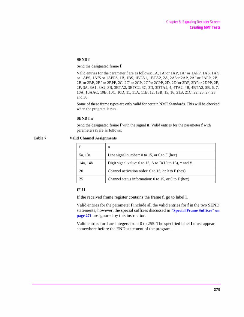
Chapter 8, Signaling Decoder ScreenCreating NMT Tests
SEND f
Send the designated frame f.
Valid entries for the parameter f are as follows: 1A, 1A’ or 1AP, 1A’’ or 1APP, 1AS, 1A’S or 1APS, 1A’’S or 1APPS, 1B, 1BS, 1BTA1, 1BTA2, 2A, 2A’ or 2AP, 2A’’ or 2APP, 2B, 2B’ or 2BP, 2B’’ or 2BPP, 2C, 2C’ or 2CP, 2C’’or 2CPP, 2D, 2D’ or 2DP, 2D’’ or 2DPP, 2E, 2F, 3A, 3A1, 3A2, 3B, 3BTA2, 3BTC2, 3C, 3D, 3DTA2, 4, 4TA2, 4B, 4BTA2, 5B, 6, 7, 10A, 10AAC, 10B, 10C, 10D, 11, 11A, 11B, 12, 13B, 15, 16, 21B, 21C, 22, 26, 27, 28 and 30.
Some of these frame types are only valid for certain NMT Standards. This will be checked when the program is run.
SEND f n
Send the designated frame f with the signal n. Valid entries for the parameter f with parameters n are as follows:
IF f l
If the received frame register contains the frame f, go to label l.
Valid entries for the parameter f include all the valid entries for f in the two SEND statements; however, the special suffixes discussed in "Special Frame Suffixes" on page 271 are ignored by this instruction.
Valid entries for l are integers from 0 to 255. The specified label l must appear somewhere before the END statement of the program.
Table 7 Valid Channel Assignments
f n
5a, 13a Line signal number: 0 to 15, or 0 to F (hex)
14a, 14b Digit signal value: 0 to 13, A to D(10 to 13), * and #.
20 Channel activation order: 0 to 15, or 0 to F (hex)
25 Channel status information: 0 to 15, or 0 to F (hex)
279
Chapter 8, Signaling Decoder ScreenCreating NMT Tests
CLEAR
Clear the received frame register. This statement should appear before an IF f l statement in the test program.
SET n m
Set the counter n to the value m.
Valid entries for the parameter n are integers 1 and 2. Valid entries for m are integers from 0 to 255.
REPEAT n l
Decrement the counter n by one and go to the label l if the counter value is still greater than 0.
Valid entries for n are 1 and 2. Valid entries for l are integers from 0 to 255. The specified counter n must have been set with a SET n m statement previously in the test program. The label l must appear somewhere in the test program before the END statement.
WAIT n
Wait n bits with no data being sent.
Valid entries for the parameter n are integers from 0 to 4095. The actual wait time depends on the data rate setting, in bits-per-second, on the NMT ENCODER.
280
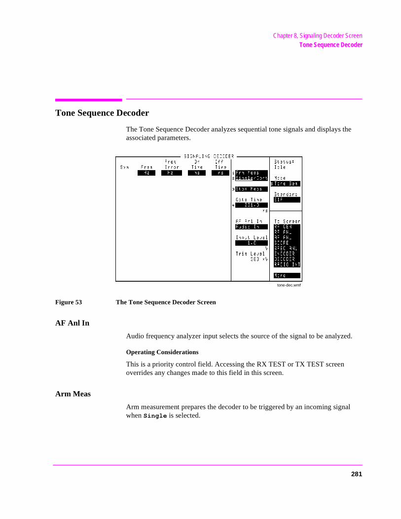
Chapter 8, Signaling Decoder ScreenTone Sequence Decoder
Tone Sequence Decoder
The Tone Sequence Decoder analyzes sequential tone signals and displays the associated parameters.
Figure 53 The Tone Sequence Decoder Screen
AF Anl In
Audio frequency analyzer input selects the source of the signal to be analyzed.
Operating Considerations
This is a priority control field. Accessing the RX TEST or TX TEST screen overrides any changes made to this field in this screen.
Arm Meas
Arm measurement prepares the decoder to be triggered by an incoming signal when Single is selected.
tone-dec.wmf
281
Chapter 8, Signaling Decoder ScreenTone Sequence Decoder
’s
Freq
This measurement column lists the tone frequency for each symbol received in the tone sequence.
Freq Error
This measurement column lists the frequency difference between the tone frequency specified for each symbol in the Tone Sequence Encoder screen and the frequency measured for each symbol in the Tone Sequence Decoder screen.
Operating Considerations
The decoder and encoder Standard fields are interactive. The standard you choose in either field is automatically selected for the other.
Gate Time
This field specifies how long the decoder analyzes a signal after it has been triggered.
Input Level
This field specifies a tone’s “on” signal level that you input (after de-emphasis if used). The higher the level of signal expected by the analyzer, the higher thetrigger level is set.
Operating Considerations
The unit-of-measure is determined by the AF Anl In setting.
The input level should be set high enough to prevent false triggering, but lowenough to allow triggering for every desired tone received.
If de-emphasis is used (by setting the AF Analyzer’s De-Emphasis field to 750 µs), the Input Level should be set to about 1/5 of the measured signallevel. For example, a 1 kHz, 1 Vpeak sinewave into the AF Analyzer input requires an Input Level of approximately 0.212 V to trigger correctly.
See Also
Trig Level field description, on page 283
282
Chapter 8, Signaling Decoder ScreenTone Sequence Decoder
the
on a
each
y two cies
ent
Off Time
This measurement column lists the length of time each tone was “off” prior tonext tone being received.
On Time
This measurement column lists the length of time each tone was “on.”
Single/Cont
This field specifies how you want the analyzer to be armed:
• Single is used to analyze and display the decoded information once each time Arm Meas is selected.
• Cont is used to automatically re-arm the analyzer and display the measurementscontinual basis until Single is selected.
Stop Meas
Selecting this field stops the analyzer when making single measurements.
Sym
The symbol column corresponds to the Tone Sequence Encoder’s symbols assigned for each tone. As each tone is analyzed, the symbol that representstone is listed in this column.
Operating Considerations
The symbol assigned to a received tone is based on the closest symbol frequencto that tone. If the frequency of the received tone is exactly half-way betweensymbol frequencies, the symbol associated with the higher of the two frequenis displayed.
Trig Level
Trigger level indicates the minimum signal level required to begin a measuremthat has been “armed.” The level is adjusted by changing the Input Level field setting.
283

Chapter 8, Signaling Decoder ScreenTone Sequence Decoder
284
9
Duplex Test Screen
285
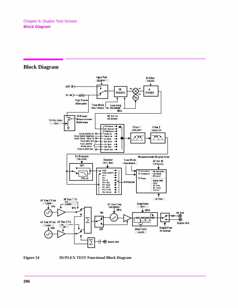
Chapter 9, Duplex Test ScreenBlock Diagram
Block Diagram
Figure 54 DUPLEX TEST Functional Block Diagram
480OWER
-EASUREMENT
2EFERENCE
!&!NL)N
&ILTER &ILTER
4UNE&REQ
2&
34!'%334!'%3
)&
&ROM!5$)/).
&ROM2ADIO)NTERFACE
4UNE-ODE
-(Z
(IGH0OWER
!TTENUATOR
2EAR0ANEL -OD).
&ROM-)#!##
&ROM!-&-
-ODULATORS
&ROM!5$)//UT
&-$ENOD
!-$EMOD
33"$EMOD
!UDIO)N
2ADIO)NT
%XT-OD
-IC-OD
&--OD
!--OD
!UDIO/UT
$E %MPASLS
US/FF
0K -AX
$ETECTOR
4UNE-ODE
-EASUREMENTS$ISPLAY!REA
(Z(0&
K(Z,0&
!UTO-ANUAL
2&).!RT
!.4).
)NPUT0ORT
2&).
480WR:ERO
,/
)&
2&
:ERO
&-$EMOD
K(Z
)&&ILTER
2-3
2-33124
0K
0K
0K
0K -AX
0K(OLD
0K (OLD
0K (D
0K -XHD
6OLTMETER
!UTO-ANUAL
2&'EN&REQ
!MPLITUDE
-(Z
D"M
&-
2&/UT
!&'EN4O
!-
/FF
&-
&-
!&'EN4O
!&'EN&REQ
!&'EN&REQ
K(Z
K(Z
K(Z
$UPLEX/UT
/UTPUT0ORT
2&/UT$UPL
!TTEN(OLD
/N/FF
!UDIO/UT
U3
/&&
48&REQ%RROR
!&!NL).
48&REQUENCY
480OWER
&-$EVIATION
!-$EPTH
!#,EVEL
3).!$3.2
$ISTN
!&&REQ
$#,EVEL
#URRENT
&-$EMOD
!&&REQ
286
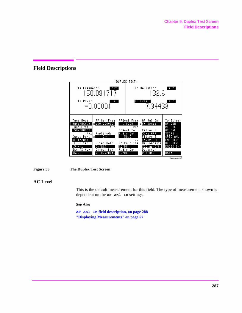
Chapter 9, Duplex Test ScreenField Descriptions
Field Descriptions
Figure 55 The Duplex Test Screen
AC Level
This is the default measurement for this field. The type of measurement shown is dependent on the AF Anl In settings.
See Also
AF Anl In field description, on page 288"Displaying Measurements" on page 57
dxscrn.wmf
287
Chapter 9, Duplex Test ScreenField Descriptions
AF Anl In
Audio frequency analyzer input selects the input for the analyzer. When selected, this field displays a list of choices.
Signals can be analyzed from three different types of inputs:
• the output of the AM, FM, or SSB demodulators
• the AUDIO IN, RADIO INTERFACE, MODULATION INPUT, MIC/ACC, and AU-DIO OUT connectors
• the signal present at the AM or FM modulators for the RF Generator
Operating Considerations
Changing this field causes the upper AF measurement to change.
This is a priority control field. Accessing the RX TEST or TX TEST screen overrides any changes made to this field in other screens.
See Also
FM Deviation field description, on page 294"Interaction Between Screens" on page 54"Displaying Measurements" on page 57
288
Chapter 9, Duplex Test ScreenField Descriptions
ier. )
the
AF Freq
This is the default measurement for this field. Selecting this field displays the following measurement choices:
SINAD
Distortion
SNR (Signal to Noise Ratio)
AF Frequency
DC Level
Current - DC only
Operating Considerations
This is a priority control field. Accessing the RX TEST or TX TEST screen overrides any changes made to this field in other screens.
SNR Operation
• Selecting SNR turns off the other audio measurement.
• The RF Generator and AF Generator 1 must be set up to provide the radio’s carr(AFGen1 is automatically turned on and off repeatedly during this measurement.
• AFGen2 must be turned off.
• The radio’s receiver’s audio output must be connected to the AUDIO IN port (setAF Anl In field to Audio In).
See Also
"Interaction Between Screens" on page 54"Displaying Measurements" on page 57
289
Chapter 9, Duplex Test ScreenField Descriptions
r is
AFGen1 Freq
This field sets the frequency for the first audio frequency sinewave generator.
AFGen1 To
This field is used to set two values for the first audio frequency generator:
• The upper field determines whether the AF signal modulates the RF Generator, ooutput through the AUDIO OUT connector.
• The lower field sets the amplitude (including Off). The AUDIO OUT level is always in volts RMS.
Operating Considerations
This is a priority control field. Accessing the RX TEST or TX TEST screen overrides any changes made to this field in other screens.
See Also
"Interaction Between Screens" on page 54
290
Chapter 9, Duplex Test ScreenField Descriptions
Amplitude
This field adjusts the amplitude of the RF Generator.
Operating Considerations
This is a priority control field. Accessing the RX TEST or TX TEST screen overrides any changes made to this field in other screens.
If a microphone is connected, and the amplitude is set to Off, keying the microphone causes the amplitude to turn on to its previous level until the microphone is no longer keyed.
See Also
Atten Hold field description, on page 291"Interaction Between Screens" on page 54"MIC/ACC" on page 514
Atten Hold
Attenuator hold prevents the fixed RF output attenuators from switching in and out, eliminating the loss of the output signal as the level is changed. This function is helpful when making squelch measurements.
Operating Considerations
When this function is set to On, the RF output level is restricted to a range of15 dB around the present Amplitude setting. Attempting to set an amplitude outside the allowed range results in an error message and beep (if the beeper is on). RF output level accuracy is greatly degraded outside the allowed range.
291
Chapter 9, Duplex Test ScreenField Descriptions
Audio Out
This field selects ac or dc coupling to the AUDIO OUT connector.
De-Emphasis
This setting selects or bypasses the 750 ms de-emphasis networks in the audio analyzer and internal speaker circuitry.
Operating Considerations
This is a priority control field. Accessing the RX TEST or TX TEST screen overrides any changes made to this field in other screens.
See Also
"Interaction Between Screens" on page 54
292
Chapter 9, Duplex Test ScreenField Descriptions
e (po-
eset. same
eset. same
dis- key,
value ferent
Detector
This setting selects the type of detector used when measuring and displaying AF signal levels.
Detector Types
• RMS displays the RMS value of signals.
• displays the RMS value of a signal multiplied by the square-root-of-2.
• Pk+ displays the positive peak value.
• Pk− displays the negative peak value.
• Pk±/2 adds the positive and negative peak values, and divides the sum by 2.
• Pk±Max compares the positive and negative peaks and displays the greater valularity is not indicated).
• Pk+ Hold displays and holds the positive peak value until the measurement is rTo reset, press the MEAS RESET key, select a different detector, or re-select thedetector.
• Pk− Hold displays and holds the negative peak value until the measurement is rTo reset, press the MEAS RESET key, select a different detector, or re-select thedetector.
• Pk±/2 Hold divides the sum of the positive and negative peak values by 2, andplays the value until the measurement is reset. To reset, press the MEAS RESETselect a different detector, or re-select the same detector.
• Pk±Mx Hold compares the positive and negative peaks and displays the greater until the measurement is reset. To reset, press the MEAS RESET key, select a difdetector, or re-select the same detector.
Operating Considerations
This is a priority control field. Accessing the RX TEST or TX TEST screen overrides any changes made to this field in other screens.
See Also
"Interaction Between Screens" on page 54
293
Chapter 9, Duplex Test ScreenField Descriptions
n
here
Ext TX Key
This field controls a switch at the MIC/ACC connector. Its intended use is to “key” an external transmitter.
See Also
"Interaction Between Screens" on page 54
FM Coupling
This field selects ac or dc coupling between the RF Generator’s frequency modulator and the rear-panel MODULATION INPUT connector. This field also alters the FM modulator to allow DCFM from internal and external modulatiosources.
FM Deviation
This is the default measurement for this field. The type of measurement listedis dependent on the AF Anl In settings.
See Also
AF Anl In field description, on page 288"Displaying Measurements" on page 57
294
Chapter 9, Duplex Test ScreenField Descriptions
TX er
IF Filter
This field selects the desired IF filter bandwidth for modulated signals being analyzed.
Input Port
This field selects the RF IN/OUT or ANT IN connector for making RF measurements. The RF IN/OUT port must be used for making TX Power measurements on this screen.
Operating Considerations
Maximum signal levels at each port are printed on the front panel.
If the RF power at the RF IN/OUT port exceeds allowable limits, a loud warning signal sounds and a message appears at the top of the screen. If this occurs, disconnect the RF power, press the MEAS RESET key, and allow the Test Set to cool off for approximately 2 minutes before making any other measurements on this port.
The ANT IN (antenna input) connector provides a highly-sensitive input for very low-level signals (such as “off-the-air” measurements). You cannot measure (RF) Power on this screen using the ANT IN port. However, low-level RF powat the ANT IN port can be measured using the Spectrum Analyzer.
CAUTION: Connecting a signal of >200 mW to the ANT IN port can cause instrument damage (althoughinternal protection circuits can typically withstand a short-duration signal of 1 or 2 Watts).
If the overpower circuit is triggered (signified by a warning message at the top ofthe screen), remove the signal from the ANT IN port, and press the MEASRESET key or turn the Test Set off and on to reset it.
295
Chapter 9, Duplex Test ScreenField Descriptions
theurs.)rs to
Output Port
This field selects the RF Generator’s output port.
Operating Considerations
Maximum signal levels at each port are printed on the front panel.
CAUTION: Applying reverse RF power to the DUPLEX OUT connector can damageinstrument. (A message is displayed when an overpower conditions occWhenever possible, use the RF IN/OUT connector when testing transceiveprevent damage from accidental transmitter keying.
If a reverse-power condition triggers the internal protection circuit, remove thereverse-power signal and press the MEAS RESET key or turn the Test Set offand on to reset it.
RF Gen Freq
This field sets the RF Generator’s frequency.
296
Chapter 9, Duplex Test ScreenField Descriptions
Tune Freq
RF analyzer tune frequency sets the center frequency for the RF signal to be analyzed.
Operating Considerations
If the Tune Mode field is set to Auto, the frequency is set by the instrument.
If the Tune Mode is set to Manual, the operator must enter the desired frequency.
See Also
Tune Mode field description, on page 297
Tune Mode
This field selects automatic or manual tuning of the RF Analyzer.
Auto tuning causes the RF Analyzer to find the signal with the greatest amplitude above −36 dBm, and set the tune frequency for that signal.
Manual tuning requires the operator to set the tune frequency for the RF signal to be analyzed.
Operating Considerations
Changing the Tune Mode also changes the RF frequency display. Automatic tuning enables the TX Frequency measurement. Manual tuning enables the TX Freq Error measurement.
After autotuning to the desired signal, select Manual tuning to prevent the Tune Freq from changing when the signal is no longer applied.
297
Chapter 9, Duplex Test ScreenField Descriptions
TX Freq Error/TX Frequency
This measurement displays transmitter frequency error or absolute Transmitter Frequency, depending on the Tune Mode setting.
See Also
Tune Mode field description (this page)
TX Power
Transmitter power measures RF power at the RF IN/OUT port.
Operating Considerations
Maximum signal levels at each port are printed on the front panel.
Only the RF IN/OUT port can be used for measuring TX Power on this screen. When the Input Port is set to Ant, four dashes (- - - -) appear in place of digits for this measurement.
Use the Spectrum Analyzer to measure low-level RF power (≤200 mW) at the ANT IN port.
CAUTION: Connecting a signal of >200 mW to the ANT IN port can cause instrument damage (althoughinternal protection circuits can typically withstand a short-duration signal of 1 or 2 Watts).
If the overpower circuit is triggered (signified by a warning message at the top ofthe screen), remove the signal from the ANT IN port, and press the MEASRESET key or turn the Test Set off and on to reset it.
See Also
Input Port field description, on page 295 (Operating Considerations) TX Power field description, on page 426TX Pwr Zero field description, on page 427.
298
10
Signaling Encoder (AF Generator 2)
299

Chapter 10, Signaling Encoder (AF Generator 2)Field Descriptions for Encoder Modes
as an EX
Field Descriptions for Encoder Modes
The Encoder (AF Generator 2) uses several screens to generate various signaling formats. These screens are accessed by selecting ENCODER from the To Screen menu, and then selecting the Mode field.
The screen and field descriptions for each Encoder screen are listed in the following order:
• AMPS/NAMPS-TACS/NTACS • CDCSS (Continuous Digital Controlled Squelch System) • Digital Paging • DTMF (Dual-Tone-Multi-Frequency Signaling Encoder)• EDACS (Enhanced Digital Access Communication System) • Function Generator • LTR (Logic Trunked Radio: Registered trademark of EF Johnson Company) • MPT 1327 Trunked Radio • NMT (Nordic Mobile Telephone) • Tone Sequence
When the Test Set is turned on, AFGen1 defaults to 3 kHz FM at a 1 kHz rate. This can interfere with many Encoder signaling formats also being used FM source. Therefore, we recommend you turn AFGen1 off on the RX TEST, DUPLTEST, or RF GENERATOR screen before using the encoder.
300
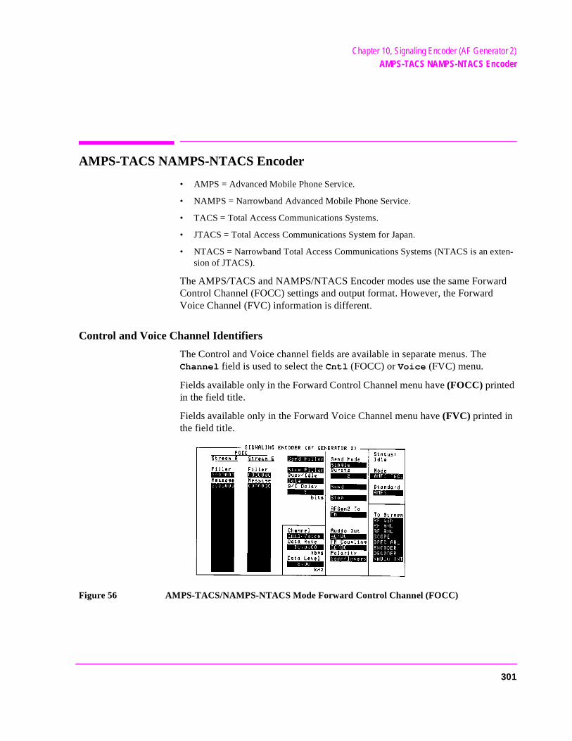
Chapter 10, Signaling Encoder (AF Generator 2)AMPS-TACS NAMPS-NTACS Encoder
ten-
AMPS-TACS NAMPS-NTACS Encoder
• AMPS = Advanced Mobile Phone Service.
• NAMPS = Narrowband Advanced Mobile Phone Service.
• TACS = Total Access Communications Systems.
• JTACS = Total Access Communications System for Japan.
• NTACS = Narrowband Total Access Communications Systems (NTACS is an exsion of JTACS).
The AMPS/TACS and NAMPS/NTACS Encoder modes use the same Forward Control Channel (FOCC) settings and output format. However, the Forward Voice Channel (FVC) information is different.
Control and Voice Channel Identifiers
The Control and Voice channel fields are available in separate menus. The Channel field is used to select the Cntl (FOCC) or Voice (FVC) menu.
Fields available only in the Forward Control Channel menu have (FOCC) printed in the field title.
Fields available only in the Forward Voice Channel menu have (FVC) printed in the field title.
Figure 56 AMPS-TACS/NAMPS-NTACS Mode Forward Control Channel (FOCC)
1 f
301
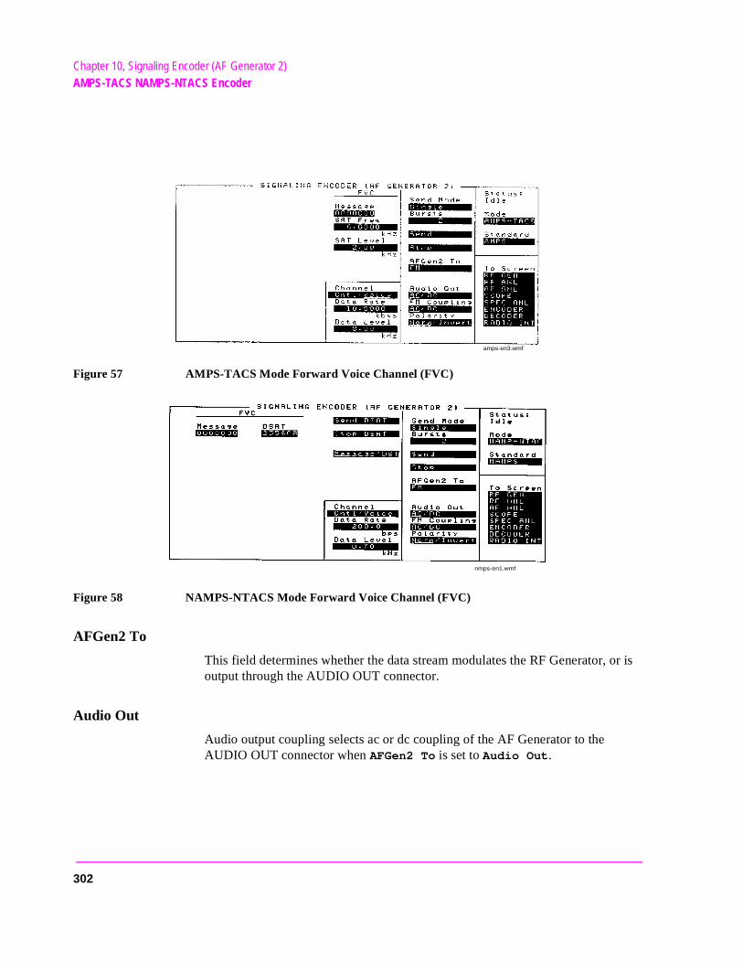
Chapter 10, Signaling Encoder (AF Generator 2)AMPS-TACS NAMPS-NTACS Encoder
Figure 57 AMPS-TACS Mode Forward Voice Channel (FVC)
Figure 58 NAMPS-NTACS Mode Forward Voice Channel (FVC)
AFGen2 To
This field determines whether the data stream modulates the RF Generator, or is output through the AUDIO OUT connector.
Audio Out
Audio output coupling selects ac or dc coupling of the AF Generator to the AUDIO OUT connector when AFGen2 To is set to Audio Out.
amps-en3.wmf
nmps-en1.wmf
302
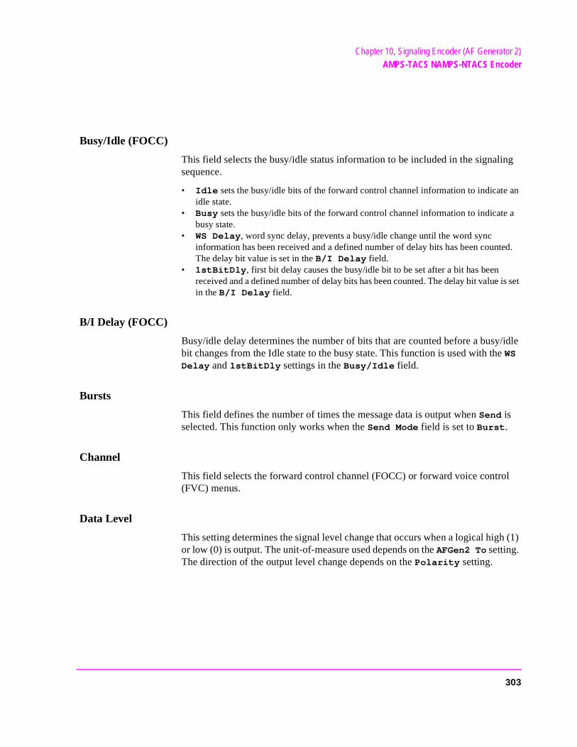
Chapter 10, Signaling Encoder (AF Generator 2)AMPS-TACS NAMPS-NTACS Encoder
an
a
ted.
is set
Busy/Idle (FOCC)
This field selects the busy/idle status information to be included in the signaling sequence.
• Idle sets the busy/idle bits of the forward control channel information to indicateidle state.
• Busy sets the busy/idle bits of the forward control channel information to indicatebusy state.
• WS Delay, word sync delay, prevents a busy/idle change until the word sync information has been received and a defined number of delay bits has been counThe delay bit value is set in the B/I Delay field.
• 1stBitDly, first bit delay causes the busy/idle bit to be set after a bit has been received and a defined number of delay bits has been counted. The delay bit valuein the B/I Delay field.
B/I Delay (FOCC)
Busy/idle delay determines the number of bits that are counted before a busy/idle bit changes from the Idle state to the busy state. This function is used with the WS Delay and 1stBitDly settings in the Busy/Idle field.
Bursts
This field defines the number of times the message data is output when Send is selected. This function only works when the Send Mode field is set to Burst.
Channel
This field selects the forward control channel (FOCC) or forward voice control (FVC) menus.
Data Level
This setting determines the signal level change that occurs when a logical high (1) or low (0) is output. The unit-of-measure used depends on the AFGen2 To setting. The direction of the output level change depends on the Polarity setting.
303
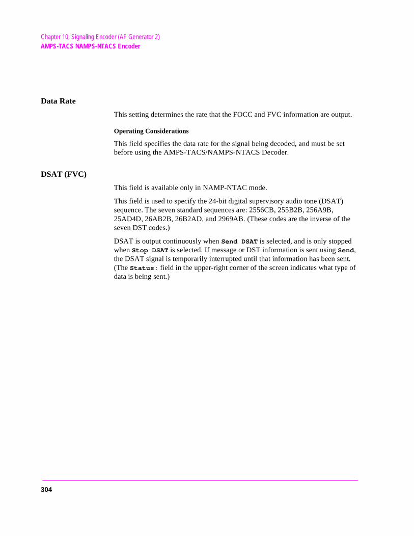
Chapter 10, Signaling Encoder (AF Generator 2)AMPS-TACS NAMPS-NTACS Encoder
Data Rate
This setting determines the rate that the FOCC and FVC information are output.
Operating Considerations
This field specifies the data rate for the signal being decoded, and must be set before using the AMPS-TACS/NAMPS-NTACS Decoder.
DSAT (FVC)
This field is available only in NAMP-NTAC mode.
This field is used to specify the 24-bit digital supervisory audio tone (DSAT) sequence. The seven standard sequences are: 2556CB, 255B2B, 256A9B, 25AD4D, 26AB2B, 26B2AD, and 2969AB. (These codes are the inverse of the seven DST codes.)
DSAT is output continuously when Send DSAT is selected, and is only stopped when Stop DSAT is selected. If message or DST information is sent using Send, the DSAT signal is temporarily interrupted until that information has been sent. (The Status: field in the upper-right corner of the screen indicates what type of data is being sent.)
304
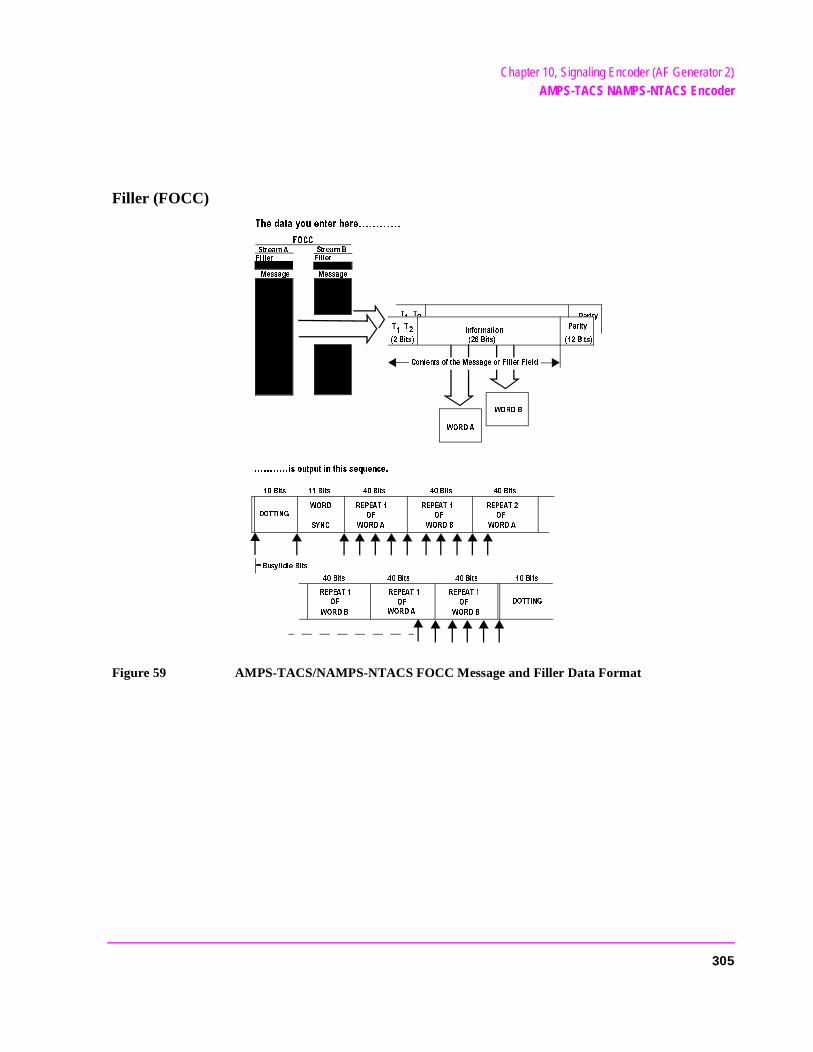
Chapter 10, Signaling Encoder (AF Generator 2)AMPS-TACS NAMPS-NTACS Encoder
Filler (FOCC)
Figure 59 AMPS-TACS/NAMPS-NTACS FOCC Message and Filler Data Format
4
"ITS
4 4
4
"ITS
)NFORMATION
0ARITY
0ARITY
"ITS
#ONTENTSOFTHE-ESSAGEOR&ILLER&IELD
7/2$"
7/2$!
ISOUTPUTINTHISSEQUENCE
"ITS "ITS "ITS "ITS "ITS
$/44).'
7/2$
39.#
2%0%!4
/&
7/2$!
2%0%!4
/&
7/2$"
2%0%!4
/&
7/2$!
2%0%!4 2%0%!4 2%0%!4
7/2$" 7/2$"
/& /&
7/2$!
$/44).'
"ITS"ITS"ITS "ITS
"USY)DLE"ITS
4HEDATAYOUENTERHERE
&/##
3TREAM!
3TREAM"
-ESSAGE-ESSAGE
&ILLER
&ILLER
/&
305
Chapter 10, Signaling Encoder (AF Generator 2)AMPS-TACS NAMPS-NTACS Encoder
Each Filler field contains 7 hexadecimal characters representing the 2 type bits and 26 information bits of the control filler/message word. The dotting, word sync, and parity bits are generated automatically.
Operating Considerations
The control filler is sent continuously when Send Filler is selected, or after a control message has been sent using Send. The control message is stopped whenever Stop Filler, Filler, Channel, Data Rate, Polarity, or AFGen2 To is selected.
Both filler fields must be full (seven digits) for the forward control channel information to be structured correctly. Do not leave any blank spaces.
FM Coupling
This field alters the FM modulator to allow DCFM from internal and external modulation sources. This field also selects ac or dc coupling between the RF Generator’s frequency modulator and the rear-panel MODULATION INPUT connector.
306
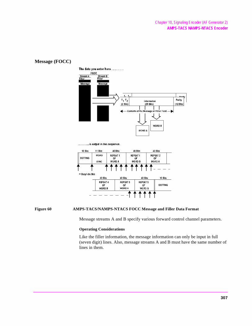
Chapter 10, Signaling Encoder (AF Generator 2)AMPS-TACS NAMPS-NTACS Encoder
Message (FOCC)
Figure 60 AMPS-TACS/NAMPS-NTACS FOCC Message and Filler Data Format
Message streams A and B specify various forward control channel parameters.
Operating Considerations
Like the filler information, the message information can only be input in full (seven digit) lines. Also, message streams A and B must have the same number of lines in them.
4
"ITS
4
4
4
"ITS
)NFORMATION
0ARITY
0ARITY
"ITS
#ONTENTSOFTHE-ESSAGEOR&ILLER&IELD
7/2$"
7/2$!
ISOUTPUTINTHISSEQUENCE
"ITS "ITS "ITS "ITS "ITS
$/44).'
7/2$
39.#
2%0%!4
/&
7/2$!
2%0%!4
/&
7/2$"
2%0%!4
/&
7/2$!
2%0%!4 2%0%!4 2%0%!4
7/2$" 7/2$"
/& /&
7/2$!
$/44).'
"ITS"ITS"ITS "ITS
"USY)DLE"ITS
4HEDATAYOUENTERHERE
&/##
3TREAM!
3TREAM"
-ESSAGE-ESSAGE
&ILLER
&ILLER
/&
307
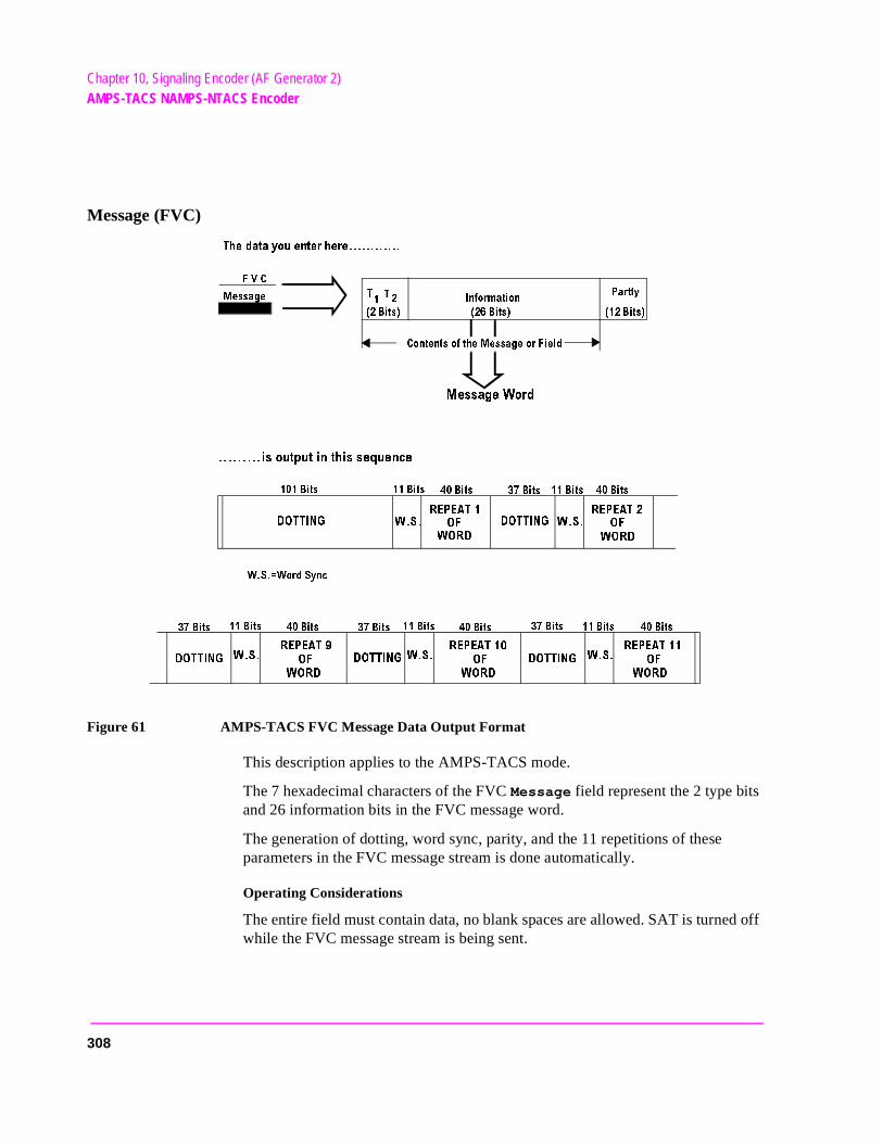
Chapter 10, Signaling Encoder (AF Generator 2)AMPS-TACS NAMPS-NTACS Encoder
Message (FVC)
Figure 61 AMPS-TACS FVC Message Data Output Format
This description applies to the AMPS-TACS mode.
The 7 hexadecimal characters of the FVC Message field represent the 2 type bits and 26 information bits in the FVC message word.
The generation of dotting, word sync, parity, and the 11 repetitions of these parameters in the FVC message stream is done automatically.
Operating Considerations
The entire field must contain data, no blank spaces are allowed. SAT is turned off while the FVC message stream is being sent.
#ONTENTSOFTHE-ESSAGEOR&IELD
4
4
0ARTTY
"ITS "ITS "ITS
-ESSAGE7ORD
)NFORMATION
&6#
-ESSAGE
ISOUTPUTINTHISSEQUENCE
4HEDATAYOUENTERHERE
$/44).'
73
2%0%!4
/&
7/2$
2%0%!4
/&
7/2$
$/44).'
73
73 73 73
$/44).' $/44).'
2%0%!4 2%0%!4 2%0%!4
/& /& /&
7/2$ 7/2$ 7/2$
"ITS "ITS
"ITS
"ITS
"ITS
"ITS
"ITS
"ITS
"ITS
"ITS
"ITS"ITS
"ITS
$/44).'
"ITS
"ITS
737ORD3YNC
308
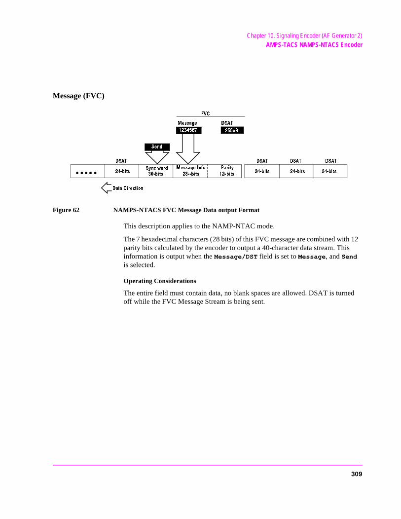
Chapter 10, Signaling Encoder (AF Generator 2)AMPS-TACS NAMPS-NTACS Encoder
Message (FVC)
Figure 62 NAMPS-NTACS FVC Message Data output Format
This description applies to the NAMP-NTAC mode.
The 7 hexadecimal characters (28 bits) of this FVC message are combined with 12 parity bits calculated by the encoder to output a 40-character data stream. This information is output when the Message/DST field is set to Message, and Send is selected.
Operating Considerations
The entire field must contain data, no blank spaces are allowed. DSAT is turned off while the FVC Message Stream is being sent.
0ARITY
BITS
-ESSAGE)NFO
BITS
BITS BITS BITS BITS
$3!4 $3!4 $3!4 $3!4
3YNCWORD
BITS
-ESSAGE $3!4
&6#
$ATA$IRECTION
3END
"
309
Chapter 10, Signaling Encoder (AF Generator 2)AMPS-TACS NAMPS-NTACS Encoder
Message/DST (FVC)
This field is available only in NAMP-NTAC mode.
This field determines what type of data is sent when Send is selected:
1. Selecting Message causes the contents of the Message field to be output. 2. Selecting DST causes the digital signaling tone sequence to be output. The sequence
sent is the inverse of the sequence entered in the DSAT field, and is automatically de-termined by the Encoder.
The DST values are: DAA934, DAA4D4, DA9564, DA52B2, D954D4, D94D52, and D69654.
Polarity
This setting determines the relationship between the signaling logic levels and the effect on the modulated signal.
Normal Operation. When this field is set to Norm, a logical high (1) causes the output level of the AF Generator to be more positive. The peak level is listed in the Data Level field. A logical low (0) causes the level to become negative by the same amount.
Inverted Operation. When this field is set to Invert, a logical high (1) causes the output level of the AF Generator to be more negative. The peak level is listed in the Data Level field. A logical low (0) causes the level to become positive by the same amount.
310
Chapter 10, Signaling Encoder (AF Generator 2)AMPS-TACS NAMPS-NTACS Encoder
ng
s on
y
SAT Freq (FVC)
This field is available only in AMPS-TACS mode.
This field sets the supervisory audio tone’s frequency. This signal is sent continuously whenever the FVC is selected, except while the Message is beisent.
SAT Level (FVC: AMPS-TACS)
This field sets the supervisory audio tone’s level. The unit-of-measure dependthe AFGen2 To setting.
Operating Considerations
SAT is turned off while the FVC message stream is being sent.
Send
Selecting this field causes the FVC or FOCC message to be output.
Operating Considerations
When sending an FOCC message stream, the contents of the Filler are continuously output after the message data has been sent. Stop Filler is used to stop the output.
Send Filler (FOCC)
Selecting this field causes the contents of the Filler fields for Stream A and Stream B to be output. The fillers continue to be output until Stop Filler is selected.
Send DSAT (FVC)
This field is available only in NAMP-NTAC mode.
Selecting this field causes the contents (24 bits) of the DSAT field to be continuously output until Stop DSAT is selected. If a message or DST is sent bselecting Send, the DSAT data is output continuously after the message is output.
311
Chapter 10, Signaling Encoder (AF Generator 2)AMPS-TACS NAMPS-NTACS Encoder
Send Mode
This field selects the mode used when Send is selected to output the message.
• Single outputs the entire message once.
• Burst outputs the Message the number of times specified in the Bursts field.
• Cont causes the message to be output continuously until Stop is selected.
• Step is not used in the AMPS-TACS mode.
Standard
This field selects the signaling standard used for your radio. The standard values used for each signaling format are automatically filled-in when the standard is selected.
Stop
Selecting this field stops the message being output.
Stop DSAT (FVC)
This field is available only in NAMP-NTAC mode.
Selecting this field stops the digital supervisory audio tone being output.
Stop Filler (FOCC)
Selecting this field stops the Filler information from being output after Send Filler or Send is used.
312
Chapter 10, Signaling Encoder (AF Generator 2)Using the AMPS-TACS, NAMPS-NTACS Encoder
Using the AMPS-TACS, NAMPS-NTACS Encoder
Using This Information
This screen is used to create various types of cellular telephone data streams. Selecting the Standards field displays a list of the supported signaling formats.
The theory and applications of cellular telephone systems are beyond the scope of this manual. The field descriptions describe their basic functions, and are not intended to be used as tutorial information.
If additional information is needed, refer to the many technical manuals available on the subject of cellular telephones.
Automated Test Software
Hewlett-Packard offers software packages to test your cellular phone in a fraction of the time normally required for manual testing. You can choose any combination of tests, from full parametric testing, to a single test. The software is shipped on a memory card that inserts directly into your Test Set, and it comes with complete documentation and a blank SRAM memory card for storing your test procedures and test data.
Encoder/Decoder Interaction
The AMPS-TACS/NAMPS-NTACS Encoder acts like a base station transmitter, creating Forward Control and Voice channel information (FOCC/FVC). The AMPS-NAMPS-TACS/NTACS Decoder acts like a base station receiver, analyzing Reverse Control and Voice channel signals (RECC/RVC).
The decoder uses the encoder’s Data Rate setting to specify how fast the incoming message is being sent. Therefore, when using the decoder, you must first specify the data rate in the encoder.
313
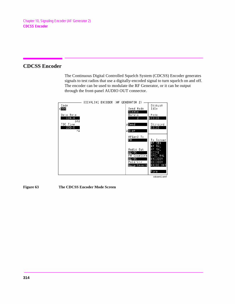
Chapter 10, Signaling Encoder (AF Generator 2)CDCSS Encoder
CDCSS Encoder
The Continuous Digital Controlled Squelch System (CDCSS) Encoder generates signals to test radios that use a digitally-encoded signal to turn squelch on and off. The encoder can be used to modulate the RF Generator, or it can be output through the front-panel AUDIO OUT connector.
Figure 63 The CDCSS Encoder Mode Screen
cdcsen1.wmf
314
Chapter 10, Signaling Encoder (AF Generator 2)CDCSS Encoder
rator,
AFGen2 To
This audio frequency generator control contains two fields:
• The upper field determines whether the CDCSS Encoder modulates the RF Geneor is output through AUDIO OUT.
• The lower field sets the amplitude (including Off).
Audio Out
Audio out coupling selects ac or dc coupling of the encoder to the AUDIO OUT connector when the upper AFGen2 To field is set to Audio Out.
Operating Considerations
The CDCSS encoder creates data streams using squarewaves. For optimum waveform quality, set this field to DC when using the AUDIO OUT connector. This is especially beneficial at low data rates.
Bursts
This field defines the number of data streams output each time Send is selected. This function works only when the Send Mode field is set to Burst.
Code
This field defines the 3-digit octal code used to identify the radio being accessed.
Data Rate
This field specifies how fast the data stream is output in bits-per-second.
This setting is also used to determine the Turn Off Code frequency (TOC frequency Hz = Data Rate in bps). Example: 1000 bps = 1 kHz
Operating Considerations
This field is also used by the CDCSS Signaling Decoder screen to approximate the data rate for the signal being decoded.
315
Chapter 10, Signaling Encoder (AF Generator 2)CDCSS Encoder
s and
r, f
re
FM Coupling
This field alters the FM modulator to allow DCFM from internal and external modulation sources. This field also selects ac or dc coupling between the RF Generator’s frequency modulator and the rear-panel MODULATION INPUT connector.
Operating Considerations
This field should be set to DC whenever the AFGen2 To field is set to FM; this provides better modulation response at low data rates.
Polarity
This setting determines the relationship between the data stream’s logic levelthe effect on the modulated signal.
This function is helpful to restore the proper data polarity when the transmitterepeater, or receiver used in your communications system has an odd number oinversions; causing the received data to be inverted when decoded. (This is common when a signal is translated to a lower frequency using an LO whosefrequency is higher than the signal’s frequency; or when inverting amplifiers aused.)
Normal Operation. When this field is set to Norm, a logical high (1) causes the output level of the AF Generator to be more positive. A logical low (0) causes the level to become negative by the same amount.
Inverted Operation. When this field is set to Invert, a logical high (1) causes the output level of the AF Generator to be more negative. A logical low (0) causes the level to become positive by the same amount.
Send
Selecting this field causes the data stream to be output.
316
Chapter 10, Signaling Encoder (AF Generator 2)CDCSS Encoder
a
Send Mode
This field selects the output format used when Send is selected to output a sequence.
• Single outputs the entire sequence once.
• Burst outputs the sequence the number of times specified in the Bursts field.
• Cont causes the sequence to be output continuously until Stop is selected.
Standard
This field selects the digitally-coded squelch standard for your radio.
Stop
Selecting this field stops the data stream being output when the Send Mode is set to Cont or Burst. After this field is selected, the current repetition of the data stream is finished, and the turn-off code is output.
TOC Time
Turn-off code time defines the length of time the turn-off code is output.
Operating Considerations
This code is always the last information output before the encoder’s Status indicator changes from Sending to Idle whether several bursts or only one datstream is sent. If no TOC is desired, set this field to 0.0000.
317
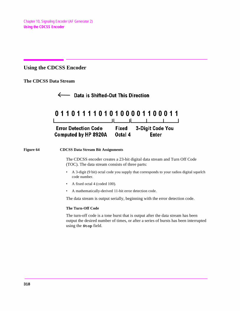
Chapter 10, Signaling Encoder (AF Generator 2)Using the CDCSS Encoder
lch
Using the CDCSS Encoder
The CDCSS Data Stream
Figure 64 CDCSS Data Stream Bit Assignments
The CDCSS encoder creates a 23-bit digital data stream and Turn Off Code (TOC). The data stream consists of three parts:
• A 3-digit (9 bit) octal code you supply that corresponds to your radios digital squecode number.
• A fixed octal 4 (coded 100).
• A mathematically-derived 11-bit error detection code.
The data stream is output serially, beginning with the error detection code.
The Turn-Off Code
The turn-off code is a tone burst that is output after the data stream has been output the desired number of times, or after a series of bursts has been interrupted using the Stop field.
$ATAIS3HIFTED /UT4HIS$IRECTION
%RROR$ETECTION#ODE
#OMPUTEDBY(0!
&IXED
/CTAL %NTER
$IGIT#ODE9OU
318
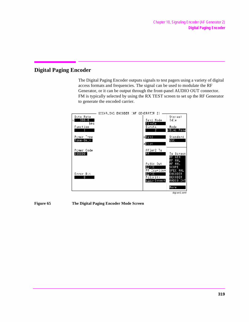
Chapter 10, Signaling Encoder (AF Generator 2)Digital Paging Encoder
Digital Paging Encoder
The Digital Paging Encoder outputs signals to test pagers using a variety of digital access formats and frequencies. The signal can be used to modulate the RF Generator, or it can be output through the front-panel AUDIO OUT connector. FM is typically selected by using the RX TEST screen to set up the RF Generator to generate the encoded carrier.
Figure 65 The Digital Paging Encoder Mode Screen
digi-en1.wmf
319
Chapter 10, Signaling Encoder (AF Generator 2)Digital Paging Encoder
s the
AFGen2 To
This field, audio frequency generator 2 to, contains two fields:
• The upper field determines whether the Digital Paging Encoder’s signal modulateRF Generator, or is output through the AUDIO OUT connector.
• The lower field sets the amplitude (including Off).
Audio Out
Audio output coupling selects ac or dc coupling of the encoder to the AUDIO OUT connector when the upper AFGen2 To field is set to Audio Out.
Operating Considerations
This field should be set to DC for best results when using the AUDIO OUT connector and low data rates.
Bursts
This field defines the number of digital data streams output each time Send is selected. This function works only when the Send Mode field is set to Burst.
Data Rate
This field specifies how fast the data stream is output in bits-per-second. Common data rates; POCSAG 512, 1200: GSC (GOLAY) 300, 600.
Error Bit
This field enables you to cause an error for a specific bit in the encoded message stream.
320
Chapter 10, Signaling Encoder (AF Generator 2)Digital Paging Encoder
r’s
r d to the
FM Coupling
This field alters the FM modulator to allow DCFM from internal and external modulation sources. This field also selects ac or dc coupling between the RF Generator’s frequency modulator and the rear-panel MODULATION INPUT connector.
Operating Considerations
This field should be set to DC whenever the AFGen2 To field is set to FM; this provides better modulation response at low data rates.
Function
This setting specifies which of the four types of messages to send. The pageresponse is determined by the Pager Type field setting and the pager’s configuration.
For example, when testing a POCSAG pager set for tone-only operation, functions 00 through 11 typically correspond to the pager beeping one to foutimes. If the pager is set for Alpha-Numeric operation, the functions correspona combination of the number of beeps and the type of message displayed bypager.
Mssg Length
The Message Length field specifies the number of characters output from thePager Numeric/Alpha-Numeric field.
This field is only displayed when the Pager Type is set to Numeric or Alpha-Num.
321

Chapter 10, Signaling Encoder (AF Generator 2)Digital Paging Encoder
s and
tive
Pager Alpha-Numeric Message
This field specifies the message you are sending to an alpha-numeric format pager.
This field is only displayed when the Pager Type is set to Numeric or Alpha-Num.
Pager Code
This field is used to identify the individual code number (address) of the pager you are testing.
Pager Numeric Message
This field specifies the message you are sending to a numeric format pager.
This field is only displayed when the Pager Type is set to Numeric or Alpha-Num.
Pager Type
This field specifies the way your pager responds to a received signal: Tone-Only (beeps), Numeric (displays numbers), or Alpha-Numeric (displays numbers and other characters).
Polarity
This setting determines the relationship between the data stream’s logic levelthe effect on the modulated signal.
Normal Operation. When this field is set to Norm, a logical high (1) causes the output level of the AF Generator to be more positive (causing a positive frequencydeviation when FM is used). A logical low (0) causes the level to become negaby the same amount (resulting in negative FM deviation).
Inverted Operation. When this field is set to Invert, a logical high (1) causes the output level of the AF Generator to be more negative (causing a negative FM deviation). A logical low (0) causes the level to become positive by the sameamount (resulting in positive FM deviation).
322
Chapter 10, Signaling Encoder (AF Generator 2)Digital Paging Encoder
Send
Selecting this field causes the entire data stream to be output (including the preamble, address, and message).
Send Mode
This field selects the output format used when Send is selected to output a sequence.
• Single outputs the entire sequence once.
• Burst outputs the sequence the number of times specified in the Bursts field.
• Cont causes the sequence to be output continuously until Stop is selected.
Standard
This field selects the digital paging standard for the pager being tested, POCSAG or GSC (Golay Sequential Code).
Stop
Selecting this field stops the data stream being output.
323
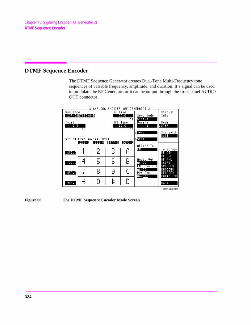
Chapter 10, Signaling Encoder (AF Generator 2)DTMF Sequence Encoder
used DIO
DTMF Sequence Encoder
The DTMF Sequence Generator creates Dual-Tone Multi-Frequency tone sequences of variable frequency, amplitude, and duration. It’s signal can be to modulate the RF Generator, or it can be output through the front-panel AUOUT connector.
Figure 66 The DTMF Sequence Encoder Mode Screen
dtmf-enc.wmf
324
Chapter 10, Signaling Encoder (AF Generator 2)DTMF Sequence Encoder
rator,
.
AFGen2 To
This audio frequency generator control contains two fields:
• The upper field determines whether the DTMF sequence modulates the RF Geneor is output through the front-panel AUDIO OUT connector.
• The lower field sets the amplitude (including Off).
The output level is the peak value for each tone pair, regardless of the Twist and Pre-Emp settings.
See Also
Twist field description, on page 327
Audio Out
Audio output coupling selects ac or dc coupling of the DTMF Sequence Generator to the AUDIO OUT connector when the upper AFGen2 To field is set to Audio Out.
Bursts
This field defines the number of sequences output each time Send is selected. This function only works when the Send Mode field is set to Burst.
FM Coupling
This field alters the FM modulator to allow DCFM from internal and external modulation sources. This field also selects ac or dc coupling between the RF Generator’s frequency modulator and the rear-panel MODULATION INPUT connector.
On Time
This field sets the length of time each DTMF tone is on during the sequence.
Off Time
This field sets the length of time each DTMF tones is off during the sequence
325
Chapter 10, Signaling Encoder (AF Generator 2)DTMF Sequence Encoder
es ing
Pre-Emp
This field determines whether the encoder’s signal passes through or bypassthe 750 ms pre-emphasis network. Pre-emphasis may be required when testsome FM receivers.
See Also
Twist field description, on page 327
Send
Selecting this field causes the DTMF sequence to be output.
Send Mode
This field selects the format used when Send is selected to output a sequence.
• Single outputs the entire sequence once.
• Burst outputs the sequence the number of times specified in the Bursts field.
• Cont causes the sequence to be output continuously until Stop is selected.
• Step allows you to output the tones in a sequence one at a time by pressing Send for each tone.
Standard
This field selects the DTMF standard used for your radio.
Stop
Selecting this field stops the sequence being output.
Symbol Frequencies (Hz)
The eight column/row frequencies are automatically entered by the Standard field setting. You can change the frequency values using the DATA keys.
326
Chapter 10, Signaling Encoder (AF Generator 2)DTMF Sequence Encoder
ne’s
e’s
is
tion e
Twist
Twist is the ratio of amplitudes (in dB) between the high frequency and low frequency tone in each DTMF pair. A positive value indicates a higher amplitude for the high frequency tones. A negative value indicates a higher amplitude for the low frequency tones.
The amplitude of the combined tones is set in the AFGen2 To field.
Twist and Pre-emphasis Interaction
Twist and Pre-emphasis affect the relative levels of the high and low tones within each symbol (tone pair). If pre-emphasis is off, twist sets the difference in deviation (in dB) between the high and low tones. If twist is off, pre-emphasis places a 6 dB per octave difference in deviation between the high and low tones. If both twist and pre-emphasis are on, the two effects are summed.
For most conditions, set Twist to 2.5 dB, Pre-Emp on, and 60% rated deviation (3 kHz for a typical 5 kHz deviation rated receiver).
Examples of Twist and Pre-emphasis Interaction
Example 1: 3 kHz deviation, Twist 0 dB, Pre-emphasis off.
The level of each low tone and high tone individually generate 1.5 kHz deviation. The tones are summed to produce 3 kHz deviation.
Example 2: 3 kHz deviation, Twist 2.5 dB, Pre-emphasis off.
The high tone has 2.5 dB (a factor of 1.334) more deviation than the low tone. The two tones are summed to produce 3 kHz peak deviation. Therefore, the low todeviation is 1286 Hz and the high tone’s deviation is 1714 Hz.
Example 3: 3 kHz deviation, Twist 0 dB, Pre-emphasis on.
There is a 6 dB per octave difference between the high and low tones. For example, if sending a 1, which has a low tone of 697 Hz and a high tone of 1209 Hz, the high tone has a deviation of 1209/697 = 1.735 times the low tondeviation. The high tone’s deviation is then 20 × log(1209/967) = 4.78 dB higher than the low tone. Since their sum must equal 3 kHz, the low tone’s deviation1097 Hz, and the high tone’s deviation is 1903 Hz.
Example 4: 3 kHz deviation, Twist 2.5 dB, Pre-emphasis on.
If sending a 1 (697 Hz low tone and 1209 Hz high tone), the high tone’s deviais 1.334 (see example 2) × 1.735 (see example 3) approximately 2.314 times thlow tone’s deviation. Since the peak deviation of their sum is 3 kHz, the low tone’s deviation is 905.5 Hz and the high tone’s deviation is 2094.5 Hz.
327
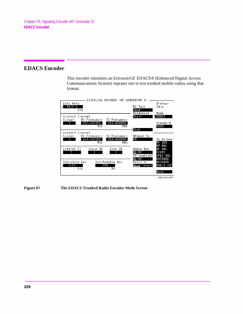
Chapter 10, Signaling Encoder (AF Generator 2)EDACS Encoder
at
EDACS Encoder
This encoder simulates an Ericsson/GE EDACS® (Enhanced Digital AccessCommunications System) repeater site to test trunked mobile radios using thformat.
Figure 67 The EDACS Trunked Radio Encoder Mode Screen
edac-en1.wmf
328
Chapter 10, Signaling Encoder (AF Generator 2)EDACS Encoder
data
tting.
sig-
l
e , this
em
AFGen2 To
This audio frequency generator control is used to specify where the encoder’sis sent:
• FM is used to frequency modulate the RF Generator. This is the normally-used se(Refer to the FM Coupling field description.)
• AM is used to amplitude modulate the RF Generator (not generally used for EDACSnaling).
• Audio Out routes the data to the front-panel AUDIO OUT connector. The signacould then be used as an external modulation source. (Refer to the Audio Out field description.)
Operating Considerations
The encoder’s digital signal level is adjusted using the Signaling Dev and Sub-Audible Dev fields. Changing the AFGen2 To setting automatically alters the unit-of-measure for both of these fields (kHz, %, or mV).
Audio Out
The audio output coupling field selects ac or dc coupling of the encoder to thAUDIO OUT connector. Because the EDACS Encoder sends low-speed datafield should be set to DC when the AUDIO OUT port is used. The AFGen2 To field must be set to Audio Out to use this function.
Control Channel, Number
This field is used to specify the Control Channel number for the EDACS syst(typically 1 to 25).
Control Channel, RX Frequency
This field is used to specify the Control Channel receive frequency for the mobile.
Control Channel, TX Frequency
This field is used to specify the Control Channel transmit frequency for the mobile.
329
Chapter 10, Signaling Encoder (AF Generator 2)EDACS Encoder
be
Data Rate
This field sets the data rate (in bits-per-second) for the high-speed signaling. The value can be changed using the keypad, or by selecting a value from the Standard field. However, the 9600 bps rate is the EDACS default, and should not be changed under most circumstances. (4800 is used for narrowband 900 MHz systems in the U.S.)
FM Coupling
This field is used to select ac or dc coupling of the encoder to the RF Generator when the AFGen2 To field is set to FM. Because the EDACS Encoder sends low-speed data, this field should be set to DC.
Group ID
This field is used to specify the group identification number for the trunked radio group your radio is set up to access.
Handshake
This field is used to get the mobile up on a working channel after it has accessed the control channel.
When Send is selected, the control channel message is output at the receive frequency specified in the Control Channel settings. The Status: field changes from Idle to Control, and the RF Analyzer is tuned to the control channel’s transmit frequency.
Operating Considerations
The control channel message must be transmitting before a handshake can initiated. The Status: field indicates Control when the control channel is transmitting, and changes to Working when the working channel is being sent.
330
Chapter 10, Signaling Encoder (AF Generator 2)EDACS Encoder
e
de
l
RF g
Logical ID
This field is used to specify the identification number of the calling radio. It should be set to the Logical ID of the radio being tested when performing transmitter tests. Generally, when performing receiver tests, it must be set to a Logical ID different from that of the radio being tested.
Polarity
This setting determines how the encoder’s digital data modulates the RF Generator. This field is usually set to Norm. Invert is used for narrowband systems. This field is automatically set to the correct polarity by the Standard field.
When this field is set to Invert, a logical high (1) causes the output level of thencoder to be negative. A logical low (0) causes the level to become positive. When using FM, the RF Generator would then produce a negative frequencydeviation for a positive-going digital transition - the opposite of the normal moof operation.
This field is automatically set to the correct polarity by the Standard field.
RX Test
When Start is selected, the encoder sends a digital message over the controchannel to tell the mobile to go to the specified working channel (called a channel assignment). Immediately after the message is sent, the RF Generator’s andAnalyzer’s frequencies are automatically changed to match the same workinchannel settings.
See Also
Handshake field description, on page 330
331
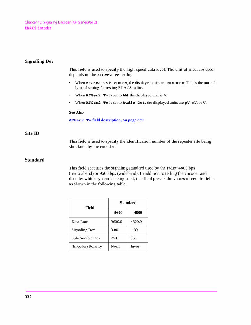
Chapter 10, Signaling Encoder (AF Generator 2)EDACS Encoder
Signaling Dev
This field is used to specify the high-speed data level. The unit-of-measure used depends on the AFGen2 To setting.
• When AFGen2 To is set to FM, the displayed units are kHz or Hz. This is the normal-ly-used setting for testing EDACS radios.
• When AFGen2 To is set to AM, the displayed unit is %.
• When AFGen2 To is set to Audio Out, the displayed units are µV, mV, or V.
See Also
AFGen2 To field description, on page 329
Site ID
This field is used to specify the identification number of the repeater site being simulated by the encoder.
Standard
This field specifies the signaling standard used by the radio: 4800 bps (narrowband) or 9600 bps (wideband). In addition to telling the encoder and decoder which system is being used, this field presets the values of certain fields as shown in the following table.
Field Standard
9600 4800
Data Rate 9600.0 4800.0
Signaling Dev 3.00 1.80
Sub-Audible Dev 750 350
(Encoder) Polarity Norm Invert
332
Chapter 10, Signaling Encoder (AF Generator 2)EDACS Encoder
Status
This field indicates what the encoder is doing.
Idle is displayed when no data is being sent.
Control is displayed when control channel data is being output.
Working is displayed when a handshake has been performed and working channel data is being sent.
Sub-Audible Dev
This field is used to specify the low-speed data level. The unit-of-measure used depends on the AFGen2 To setting.
• When AFGen2 To is set to FM, the displayed units are kHz or Hz. This is the normal-ly-used setting for testing EDACS radios.
• When AFGen2 To is set to AM, the displayed unit is %.
• When AFGen2 To is set to Audio Out, the displayed units are µV, mV, or V.
See Also
AFGen2 To field description, on page 329
Stop
This field is used to stop the control channel or working channel data from being output. The carrier continues to be output, but without the digital modulation.
Working Channel, Number
This field is used to specify the working channel number for the EDACS system (typically 1 to 25).
Working Channel: RX Frequency
This field is used to specify the working’s channel receive frequency for the mobile.
Working Channel: TX Frequency
This field is used to specify the working channel’s transmit frequency for the mobile.
333
Chapter 10, Signaling Encoder (AF Generator 2)Using the EDACS Encoder
Using the EDACS Encoder
Automated Test Software
Hewlett-Packard offers software packages to fully test your EDACS radio in a fraction of the time normally required for complete manual testing. Under software control, you can perform receiver and transmitter tests on several channels in succession very quickly.
You can choose any combination of tests, from full transmitter and receiver testing, to a single test. The software is shipped on a memory card that inserts directly into your Test Set, and it comes with complete documentation and a blank SRAM memory card for storing your test procedures and test data.
334
Chapter 10, Signaling Encoder (AF Generator 2)Using the EDACS Encoder
r’s
ge to (this
rd
lity
tion
you wer, and
Testing EDACS Mobiles
When the mobile is turned on, it automatically tunes to its pre-programmed control channel frequency. The Test Set generates the control channel’s carrier and site identification data using the RF Generator’s and the EDACS Encodesettings. (The RF carrier level for the control channel and working channel isadjusted using the Amplitude field on the DUPLEX TEST screen.) Once the mobile is receiving the Control Channel, the encoder can send a digital messathe mobile to go to a designated Working Channel for making receiver tests is called a handshake).
Testing the Mobile’s Receiver
If the working channel’s RF carrier’s level is high enough, the mobile’s receiver unsquelches to allow the modulating signal (speech or a test tone) to be heafrom your mobile’s speaker.
If the audio output (speaker) connection of your mobile is connected to the AUDIO IN connectors of the Test Set, you can then make receiver audio-quameasurements such as distortion at 1 kHz, and SINAD.
Testing the Mobile’s Transmitter
The EDACS Encoder’s information is used to help the EDACS Decoder receive and decode transmitted data from the mobile. After entering all of the informain the EDACS Encoder screen, the EDACS Decoder screen is accessed to get the mobile transmitting and to decode the digital data. With the transmitter keyed,can access the TX TEST or DUPLEX TEST screen to measure transmitter poand transmitter frequency or transmitter frequency error. You can also decodedisplay the transmitted data using the EDACS Decoder. Refer to the "EDACS Decoder" on page 241 for more information on EDACS Transmitter Testing.
335
Chapter 10, Signaling Encoder (AF Generator 2)Using the EDACS Encoder
U-t at
Mobile Receiver Test Procedure
The following procedure establishes a control channel connection between the Test Set and your mobile, and then performs a handshake to pass the mobile to a working channel. Receiver measurements can then be made.
NOTE: Each EDACS radio is pre-programmed to access a specific control channel and one or moreworking channels. Other identification information is also pre-programmed into the mobile (such as the Logical ID and Group ID numbers). You cannottest an EDACS mobile without entering these values into the Encoder.
Connect the Mobile to the Test Set
1. Press the PRESET key on the Test Set.
2. Connect the mobile’s antenna port to the Test Set’s RF IN/OUT port.
3. Connect the mobile’s audio output to the AUDIO IN HI port of the Test Set. (The ADIO IN LO port is typically only used when the mobile’s antenna port shield is nothe same potential as the audio output shield. See the AF ANALYZER screen, Audio In Lo field description, on page 99.)
4. Turn the mobile on.
336
Chapter 10, Signaling Encoder (AF Generator 2)Using the EDACS Encoder
ile.
e.
e.
at
g
g
ma-nnel
rk-ned
Get the Mobile Up on the Control Channel
1. Turn AF Generator 1 Off (to disable the default 3 kHz FM deviation). To do this, po-sition the cursor in front of the 3.00 value in the AFGen1 To field on the RF GEN-ERATOR or DUPLEX TEST screen and press the ON/OFF key.
2. Select ENCODER from the To Screen menu.
3. Select the Mode field and choose EDACS from the Choices menu.
4. Select the standard used by the radio (4800 or 9600 bps).
5. Enter the Control Channel settings.
• The Number is the system control channel number programmed into your mob
• The RX Frequency is the control channel’s receive frequency for your mobil
• The TX Frequency is the control channel’s transmit frequency for your mobil
6. Enter the Working Channel settings.
• The Number is the working channel number (programmed into your mobile) thyou want the mobile to be sent to.
• The RX Frequency is the mobile’s receive frequency for the selected workinchannel.
• The TX Frequency is the mobile’s transmit frequency for the selected workinchannel.
7. Enter the Logical ID number.
8. Enter the Group ID number.
9. Enter the Site ID number.
10. Select the Send field (under RX Test). The Status: field should now indicate Control.
11. The Test Set should now be sending the control channel’s site identification infortion to the mobile, and the mobile should indicate that it is receiving the control chadata.
12. Select the Handshake field. This tells the mobile and RF Generator to go to the woing channel frequencies. The mobile should now indicate that it is “busy”, and is tuto a working channel (this is a “receiver handshake”). The Status: field should now indicate Working.
337
Chapter 10, Signaling Encoder (AF Generator 2)Using the EDACS Encoder
eaker
.
Make Receiver Measurements
1. Press the RX key to access the RX TEST screen.
2. Turn AF Generator 1 On. (Position the cursor in front of the Off entry in the lower part of the AFGen1 To field, and press the ON/OFF key.) The entry should now read 3.00. The working channel is now being modulated at a 1 kHz rate (AFGen1 Freq) with 3 kHz deviation (AFGen1 To) in addition to the subaudible EDACS signaling from the encoder (AFGen2).
3. Set the volume control on your mobile to about half of full scale. (You may or may not hear the 1 kHz tone from your radio’s speaker, depending on how the external spconnection affects the speaker.)
4. Turn up the VOLUME of the Test Set. You should be able to hear the 1 kHz tone
Your mobile’s SINAD is displayed, as well as the AC Level of the audio output. You can now change the RF Generator’s Amplitude setting to check sensitivity, or select the SINAD measurement to list and access other available audio measurements.
338
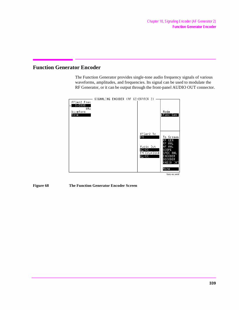
Chapter 10, Signaling Encoder (AF Generator 2)Function Generator Encoder
Function Generator Encoder
The Function Generator provides single-tone audio frequency signals of various waveforms, amplitudes, and frequencies. Its signal can be used to modulate the RF Generator, or it can be output through the front-panel AUDIO OUT connector.
Figure 68 The Function Generator Encoder Screen
func-ec.wmf
339
Chapter 10, Signaling Encoder (AF Generator 2)Function Generator Encoder
e RF
AFGen2 Freq
This field sets the tone frequency for the Function Generator.
AFGen2 To
This audio frequency generator control contains two fields:
• The upper field determines whether the Function Generator’s signal modulates thGenerator, or is output through the AUDIO OUT connector.
• The lower field sets the amplitude (including Off).
Operating Considerations
When the Waveform field is set to Sine and the signal is output to the AUDIO OUT connector, the amplitude can be set in units of rms or peak voltage. This is done in the Sine Units field that appears when Audio Out is selected. In all other cases, the amplitude is always set in peak voltage.
Audio Out
Audio output coupling selects ac or dc coupling of the Function Generator to the AUDIO OUT connector when the upper AFGen2 To field is set to Audio Out.
FM Coupling
This field alters the FM modulator to allow DCFM from internal and external modulation sources. This field also selects ac or dc coupling between the RF Generator’s frequency modulator and the rear-panel MODULATION INPUT connector.
Sine Units
This field specifies whether the signal’s output is in units of rms or peak. Thisfield is only present when the AFGen2 To field is set to Audio Out.
340

Chapter 10, Signaling Encoder (AF Generator 2)Function Generator Encoder
Waveform
This field selects the desired waveform for AF Generator 2. The available waveforms are as follows:
Sine wave
Square wave
Triangle wave
Ramp (positive-going and negative-going)
DC±
Universal Noise
Gaussian Noise
341
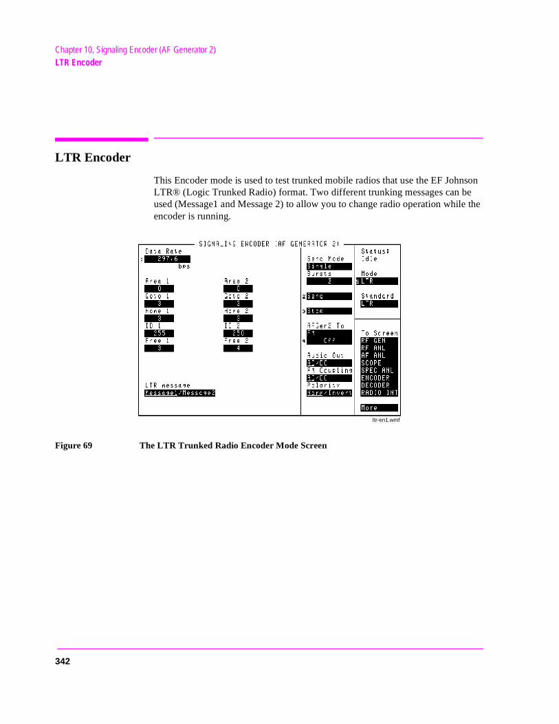
Chapter 10, Signaling Encoder (AF Generator 2)LTR Encoder
le the
LTR Encoder
This Encoder mode is used to test trunked mobile radios that use the EF Johnson LTR® (Logic Trunked Radio) format. Two different trunking messages can be used (Message1 and Message 2) to allow you to change radio operation whiencoder is running.
Figure 69 The LTR Trunked Radio Encoder Mode Screen
Itr-en1.wmf
342
Chapter 10, Signaling Encoder (AF Generator 2)LTR Encoder
Gen-
cy
AFGen2 To
This audio frequency generator control contains two fields:
• The upper field determines whether the LTR Encoder’s signal modulates the RF erator, or is output through AUDIO OUT (normally set to FM for LTR signaling).
• The lower field sets the amplitude, including Off (typically set to 1 kHz for LTR sig-naling).
Area 1, Area 2
Enter the trunked system Area Number (0 or 1) programmed into your radio.
Audio Out
Audio output coupling selects ac or dc coupling of the LTR Encoder to the AUDIO OUT connector when the upper AFGen2 To field is set to Audio Out.
Bursts
This field defines the number of times Message 1 or Message 2 is output each time Send is selected. This function works only when the Send Mode field is set to Burst.
Data Rate
Enter the LTR signaling data rate used for your radio. The standard and default value is 297.6 bits-per-second.
FM Coupling
This field alters the FM modulator to allow DCFM from the LTR Encoder’s modulation source. This field should be set to DC when testing trunked radios.
This field also selects ac or dc coupling between the RF Generator’s frequenmodulator and the rear-panel MODULATION INPUT connector.
343
Chapter 10, Signaling Encoder (AF Generator 2)LTR Encoder
e
ator.
Free 1, Free 2
Enter the repeater number to transmit to when the radio is keyed. When channel switching is performed, you would specify any of the other repeaters in the system.
Goto 1, Goto 2
Enter the repeater number to receive when the message is sent.
Home 1, Home2
Enter the home repeater number programmed into your radio.
ID 1, ID 2
Enter the transmit or receive ID number programmed into your radio.
LTR message
This field selects which message (Message1 or Message2) is output when Send is selected. The underlined message is output.
Polarity
This setting determines the relationship between the LTR Encoder’s data stream logic levels and the effect on the modulated signal.
When this field is set to Invert, a logical high (1) causes the output level of thAF Generator to be more negative. A logical low (0) causes the level to becomepositive by the same amount.
Send
Selecting this field causes the LTR Encoder to start modulating the RF Gener
344
Chapter 10, Signaling Encoder (AF Generator 2)LTR Encoder
Send Mode
This field selects the output format used when Send is selected to output a sequence. Cont is typically used for LTR radio testing.
• Single outputs Message 1 or Message 2 once.
• Burst outputs the message the number of times specified in the Bursts field.
• Cont causes the message to be repeated continuously until Stop is selected.
• Step is not used with this encoder mode.
Standard
This field selects the trunked radio standard for your radio.
Stop
Selecting this field stops the message being output when the Send Mode is set to Cont or Burst. After this field is selected, the current repetition of the message is finished.
345
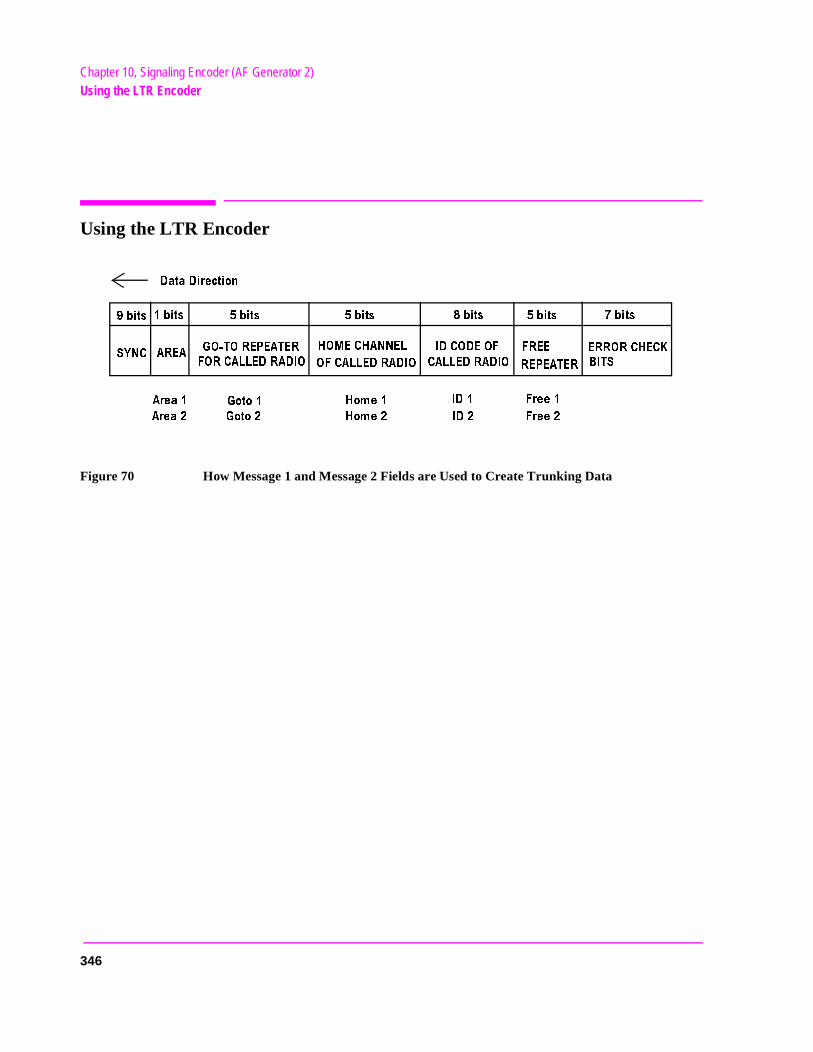
Chapter 10, Signaling Encoder (AF Generator 2)Using the LTR Encoder
Using the LTR Encoder
Figure 70 How Message 1 and Message 2 Fields are Used to Create Trunking Data
$ATA$IRECTION
BITS
BITS
BITS BITS
BITS
BITS
BITS
39.#
!2%!
'/ 4/2%0%!4%2
&/2#!,,%$2!$)/
(/-%#(!..%,
/&#!,,%$2!$)/
)$#/$%/&
#!,,%$2!$)/
&2%%
2%0%!4%2
%22/2#(%#+
")43
!REA
!REA
'OTO
'OTO
(OME
(OME )$
)$ &REE
&REE
346
Chapter 10, Signaling Encoder (AF Generator 2)Using the LTR Encoder
the .
.
to
r,
Radio Test Examples
The following procedures establish a receiver or transmitter trunked channel on the home channel.
To Test Your Receiver
To establish a trunked receiver channel on the home channel,
1. Connect the RF IN/OUT port of the Test Set to your radio’s antenna port. 2. If you want to make audio measurements, connect your radio’s speaker output to
Test Set’s AUDIO IN port(s), and turn the Test Set’s VOLUME up about half way3. Turn your radio’s volume up about half way. 4. Turn your radio on, and select the channel to test. 5. Press the PRESET key (to establish a known instrument state for this procedure)6. Access the DUPLEX TEST screen. 7. Set the Tune Mode field to Manual. 8. Set the RF Gen Freq field to the receive frequency for the selected channel. (Note
that the preset function caused the Amplitude to be set to -80 dBm, and AFGen1 isset to 1 kHz FM with 3 kHz deviation. These settings should work with your radioproduce the audio tone.)
9. Access the ENCODER screen, and select the LTR mode. 10. Enter your Area Number (0 or 1) in the Area 1 field. 11. Enter the home channel number in these fields: Goto 1, Home 1, and Free 1. (For
example, if your radio’s home channel is 2, enter 2 in all three fields.) 12. Enter the Receive ID number for your radio in the ID 1 field. 13. Set the Send Mode field to Cont. 14. Set the AFGen2 To field to FM, 1 kHz. 15. Set the FM Coupling field to DC. 16. Select Send to continuously output the encoded signal.
You should hear the 1 kHz tone from your radio and/or the Test Set’s speakeindicating that the trunked channel has been established.
If you connected the radio’s speaker to the AUDIO IN port(s), access the DUPLEX TEST screen to display the AC Level and SINAD measurements.
347
Chapter 10, Signaling Encoder (AF Generator 2)Using the LTR Encoder
.
sing
To make a 12 dB SINAD measurement
1. Set Filter 1 to 300Hz HPF and Filter 2 to 3kHz LPF.
2. Decrease the Amplitude until approximately 12 dB SINAD is displayed.
3. Use the AVG (average) function to stabilize the measurement by positioning the cursor in front of the SINAD dB field and pressing and releasing the SHIFT key, then the INCR ×10 key to access the AVG function, then press the ENTER key.
To Test Your Transmitter
To establish a trunked transmit channel on the home channel:
1. Connect the RF IN/OUT port of the Test Set to your radio’s antenna port. 2. Turn your radio on, and select the channel to test. 3. Press the PRESET key (to establish a known instrument state for this procedure)4. Access the DUPLEX TEST screen. 5. Set the Tune Mode field to Manual. 6. Enter the home channel’s transmit frequency in the Tune Freq field. 7. Enter the home channel’s receive frequency in the RF Gen Freq field. 8. Set AFGen1 To to Off. 9. Set the AF Anl In field to FM Demod. 10. Access the ENCODER screen, and select the LTR mode. 11. Set up Message 1 with idle message data:
a. Enter your Area Number (0 or 1) in the Area 1 field. b. Enter the home channel number in these fields: Goto 1, Home 1, and Free 1. c. Enter 255 in the ID 1 field to establish an idle channel.
12. Set up Message 2 with transmit message data: a. Enter your Area Number (0 or 1) in the Area 2 field. b. Enter the home channel number in these fields: Goto 2, Home 2, and Free 2. c. Enter the Transmit ID number for your radio in the ID 2 field.
13. Set the Send Mode field to Cont. 14. Set the AFGen2 To field to FM, 1 kHz. 15. Set the FM Coupling field to DC. 16. Set the LTR message field to Message1. 17. Select Send to continuously output idle message. 18. Key the transmitter. 19. Select Message2 in the LTR message field to tell your radio to transmit. If the
transmitter fails to establish a transmit channel before time-out occurs, try again uthese steps: a. De-key the transmitter. b. Select Message 1. c. Key the transmitter. d. Select Message 2.
348
Chapter 10, Signaling Encoder (AF Generator 2)Using the LTR Encoder
st
nded he change new an g an done
ram
dio any t. Set, for
Once a transmit channel is established, turn the Test Set’s VOLUME up andspeak into your radio’s microphone. You should hear your voice out of the TeSet’s speaker. Access the DUPLEX TEST screen to display the transmitter’s power and frequency error.
Performing Channel Changes
Testing the mobile’s ability to change to other receive channels when commarequires rapid RF Generator frequency changes. After the idle message on thome channel has been established (using Message 1), a message is sent tochannels (Message 2). The mobile must see the LTR-encoded carrier at the channel frequency within a few seconds to establish the new channel. You cchange the RF Generator’s frequency using a global USER key after enterinincrement value equal to the required channel offset. This procedure must bevery quickly to work.
The best way to perform a channel change is to use an HP-IB or IBASIC progto change the RF Generator’s frequency to the new channel frequency immediately after the appropriate message has been output.
Automated Test Software
Hewlett-Packard offers software packages to test your LTR-format trunked rain a fraction of the time normally required for manual testing. You can choosecombination of tests, from full transmitter and receiver testing, to a single tesThe software is shipped on a memory card that inserts directly into your Testand it comes with complete documentation and a blank SRAM memory cardstoring your test procedures and test data.
349
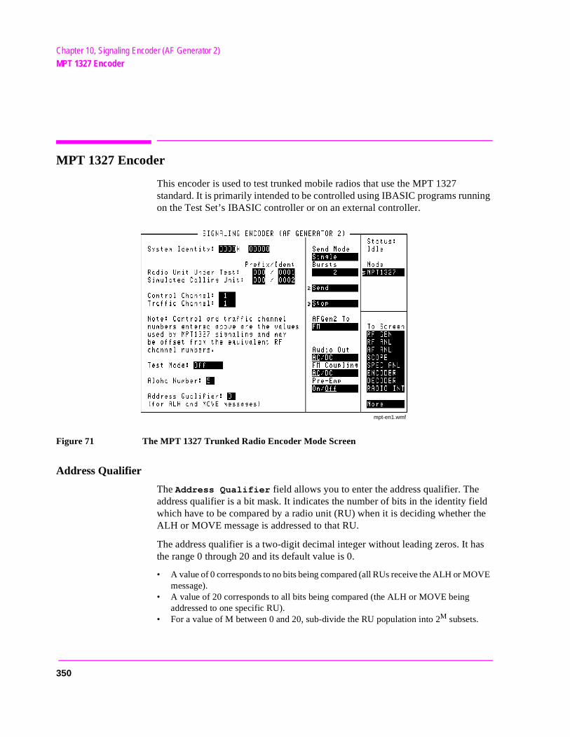
Chapter 10, Signaling Encoder (AF Generator 2)MPT 1327 Encoder
eld the
as
VE
MPT 1327 Encoder
This encoder is used to test trunked mobile radios that use the MPT 1327 standard. It is primarily intended to be controlled using IBASIC programs running on the Test Set’s IBASIC controller or on an external controller.
Figure 71 The MPT 1327 Trunked Radio Encoder Mode Screen
Address Qualifier
The Address Qualifier field allows you to enter the address qualifier. The address qualifier is a bit mask. It indicates the number of bits in the identity fiwhich have to be compared by a radio unit (RU) when it is deciding whether ALH or MOVE message is addressed to that RU.
The address qualifier is a two-digit decimal integer without leading zeros. It hthe range 0 through 20 and its default value is 0.
• A value of 0 corresponds to no bits being compared (all RUs receive the ALH or MOmessage).
• A value of 20 corresponds to all bits being compared (the ALH or MOVE being addressed to one specific RU).
• For a value of M between 0 and 20, sub-divide the RU population into 2M subsets.
mpt-en1.wmf
350
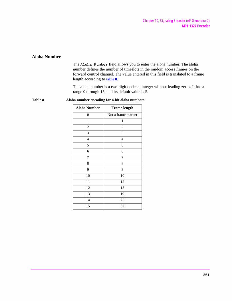
Chapter 10, Signaling Encoder (AF Generator 2)MPT 1327 Encoder
Aloha Number
The Aloha Number field allows you to enter the aloha number. The aloha number defines the number of timeslots in the random access frames on the forward control channel. The value entered in this field is translated to a frame length according to table 8.
The aloha number is a two-digit decimal integer without leading zeros. It has a range 0 through 15, and its default value is 5.
Table 8 Aloha number encoding for 4-bit aloha numbers
Aloha Number Frame length
0 Not a frame marker
1 1
2 2
3 3
4 4
5 5
6 6
7 7
8 8
9 9
10 10
11 12
12 15
13 19
14 25
15 32
351
Chapter 10, Signaling Encoder (AF Generator 2)MPT 1327 Encoder
no
s
Control Channel
The Control Channel field allows you to enter the Control Channel number.
Radio units (RU) are programmed to look for control channel signaling on a restricted set of radio channels, known as the hunt group. It is essential that the channel number on which the Test Set transmits the control channel signaling matches one of the channels in the RU’s hunt group. If there is not a match, communication will be possible.
The control channel is a four-digit decimal integer without leading zeros. It hathe range 0 through 1023, and its default value is 1.
Test Mode
The Test Mode field is used to select how the encoder is used for tests:
Selection Description
Off In this mode the signaling hardware is disabled and does not transmit data.
Control In this mode the signaling hardware is enabled and is retransmitting a basic control channel structure as defined by the content of the filler buffer. (Refer to "Forward Control Channel Message and Filler Buffers" on page 354 for an explanation of the filler buffer). One or more timeslots in the filler pattern can be overlaid by messages from the control message buffer under control of the Send field.
Traffic In this mode the signaling hardware is enabled. The filler pattern is not transmitted. Single or multi-timeslot messages can be transmitted from the traffic message buffer under the control of the Send field.
1200Hz In this mode the signaling hardware is enabled and transmits a contin-uous 1200 Hz tone (equivalent to an FFSK transmission of continu-ous ones).
1800Hz In this mode the signaling hardware is enabled and transmits a contin-uous 1800 Hz tone (equivalent to an FFSK transmission of continu-ous zeros).
Dotting In this mode the signaling hardware is enabled and transmits alternat-ing 1200 Hz and 1800 Hz tones (equivalent to an FFSK transmission of alternating ones and zeros).
352
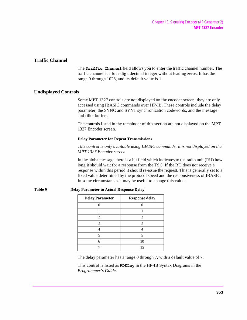
Chapter 10, Signaling Encoder (AF Generator 2)MPT 1327 Encoder
Traffic Channel
The Traffic Channel field allows you to enter the traffic channel number. The traffic channel is a four-digit decimal integer without leading zeros. It has the range 0 through 1023, and its default value is 1.
Undisplayed Controls
Some MPT 1327 controls are not displayed on the encoder screen; they are only accessed using IBASIC commands over HP-IB. These controls include the delay parameter, the SYNC and SYNT synchronization codewords, and the message and filler buffers.
The controls listed in the remainder of this section are not displayed on the MPT 1327 Encoder screen.
Delay Parameter for Repeat Transmissions
This control is only available using IBASIC commands; it is not displayed on the MPT 1327 Encoder screen.
In the aloha message there is a bit field which indicates to the radio unit (RU) how long it should wait for a response from the TSC. If the RU does not receive a response within this period it should re-issue the request. This is generally set to a fixed value determined by the protocol speed and the responsiveness of IBASIC. In some circumstances it may be useful to change this value.
The delay parameter has a range 0 through 7, with a default value of 7.
This control is listed as RDELay in the HP-IB Syntax Diagrams in the Programmer’s Guide.
Table 9 Delay Parameter to Actual Response Delay
Delay Parameter Response delay
0 0
1 1
2 2
3 3
4 4
5 5
6 10
7 15
353
Chapter 10, Signaling Encoder (AF Generator 2)MPT 1327 Encoder
Forward Control Channel Message and Filler Buffers
This control is only available using IBASIC commands; it is not displayed on the MPT 1327 Encoder screen.
The encoder screen Test Mode field selects the type of signal being transmitted by the signaling hardware (as explained in "Test Mode" on page 352). The most important modes are the Control and Traffic modes.
In the Control mode the Test Set continuously generates a slotted aloha forward control channel, as defined and controlled from IBASIC. In Traffic mode the Test Set generates individual messages, as defined and controlled from IBASIC.
These modes are central to testing MPT 1327 RUs. An RU must acquire and validate a control channel. It must also be instructed, by control channel signaling, to proceed to a traffic channel before any RF or audio measurements can be performed.
During testing it is necessary to generate the forward control channel continuously; initially, for the RU to acquire and validate the control channel for exchanging the necessary call setup signaling; thereafter, for the RU to remain locked onto the control channel, awaiting exchange of further signaling. This also prevents the RU from re-entering control channel acquisition procedures.
The exception to this is when the RU-under-test is participating in a test call on a traffic channel. It is not necessary to maintain the control channel signaling during test calls as there is only one RU in the test environment and it is on a traffic channel.
As there is only one RU, the control channel signaling comprises a fixed slotted aloha sequence with occasional variations to send specific messages (such as requests for registration (RQR), broadcast messages (BCAST), ahoy messages (AHY)).
The filler buffer contains the repeating pattern of the forward control channel. It also contains a message buffer from which selected timeslots in the filler buffer can be replaced on a one-off or repeating basis.
354
Chapter 10, Signaling Encoder (AF Generator 2)MPT 1327 Encoder
one refore e the
data the mustof data
The control channel filler buffer comprises 32 individual timeslots. It is accessed only through the HP-IB with the following command:
ENCoder:MPT1327:FILLer:DATA n,string
Where
• n is the location selector and has the range 1 through 32. • string is a string containing a signaling language command defining the content of
timeslot. Some signaling language commands also define data codewords and thetranslate to data for two or three timeslots. The signaling language commands takform of an assembly language.
NOTE: In MPT 1327 an address codeword can be followed by up to four data codewords. Acodeword occupies half of one timeslot. The signaling language definition restrictsfirmware to accept only two or four data codewords. An odd number of data codewordsbe added to occupy a whole number of timeslots. For messages with an odd number codewords the padding word must be generated by IBASIC.
An example of the format is given in the sequence of commands below. It defines a two timeslot random access frame with a broadcast message, transmitted on channel 212 of system 490116.
ENC:MPT1327:FILL:DATA 1,’ALH 0,ALLI,212,0,0,2’ENC:MPT1327:FILL:DATA 2,’ALH 0,ALLI,212,0,0,0’ENC:MPT1327:FILL:DATA 3,’BCAST 2,#H4901,0,0’
The signaling commands from such strings are assembled into 48-bit address and data codeword message values.
For an address codeword message, the timeslot (128-bits) consists of a 64-bit control channel system codeword (CCSC), followed by the address message, followed by a 16-bit parity word.
Data codeword messages are taken in pairs. Each has its own 16-bit parity word. The firmware is never supplied with an odd number of codewords. The resulting pair of 64-bit words is concatenated to again give 128-bits.
The resulting 128-bits are stored in the addressed location of the filler buffer. Figure 72 on page 356, shows a signaling instruction being processed, and should clarify this explanation.
355
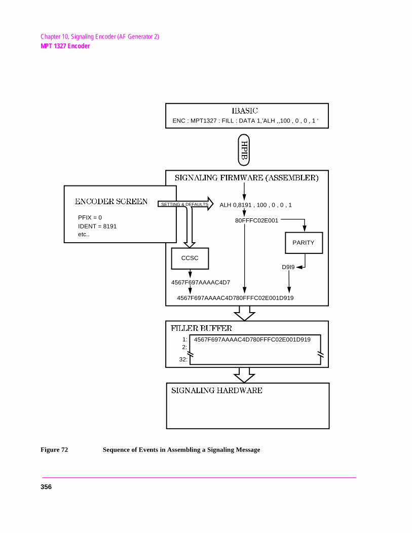
Chapter 10, Signaling Encoder (AF Generator 2)MPT 1327 Encoder
Figure 72 Sequence of Events in Assembling a Signaling Message
)"!3)#
3)'.!,).'&)2-7!2%!33%-",%2
(0)"
ENC : MPT1327 : FILL : DATA 1,’ALH ,,100 , 0 , 0 , 1 ‘
ALH 0,8191 , 100 , 0 , 0 , 1
80FFFC02E001
PARITY
CCSC
D9I9
4567F697AAAAC4D7
4567F697AAAAC4D780FFFC02E001D919
&),,%2"5&&%2
3)'.!,).'(!2$7!2%
4567F697AAAAC4D780FFFC02E001D9191:2:
32:
%.#/$%23#2%%.
PFIX = 0
IDENT = 8191etc..
SETTING & DEFAULTS
356
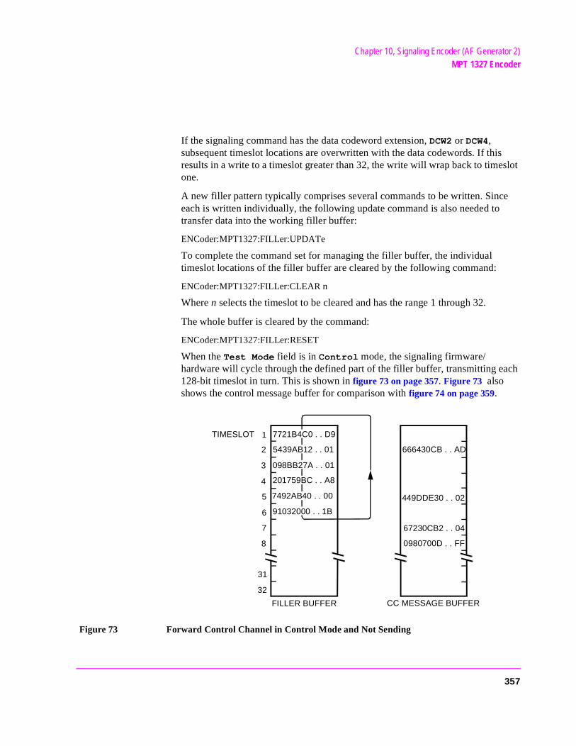
Chapter 10, Signaling Encoder (AF Generator 2)MPT 1327 Encoder
If the signaling command has the data codeword extension, DCW2 or DCW4, subsequent timeslot locations are overwritten with the data codewords. If this results in a write to a timeslot greater than 32, the write will wrap back to timeslot one.
A new filler pattern typically comprises several commands to be written. Since each is written individually, the following update command is also needed to transfer data into the working filler buffer:
ENCoder:MPT1327:FILLer:UPDATe
To complete the command set for managing the filler buffer, the individual timeslot locations of the filler buffer are cleared by the following command:
ENCoder:MPT1327:FILLer:CLEAR n
Where n selects the timeslot to be cleared and has the range 1 through 32.
The whole buffer is cleared by the command:
ENCoder:MPT1327:FILLer:RESET
When the Test Mode field is in Control mode, the signaling firmware/hardware will cycle through the defined part of the filler buffer, transmitting each 128-bit timeslot in turn. This is shown in figure 73 on page 357. Figure 73 also shows the control message buffer for comparison with figure 74 on page 359.
Figure 73 Forward Control Channel in Control Mode and Not Sending
7492AB40 . . 00
5439AB12 . . 01
098BB27A . . 01
201759BC . . A8
91032000 . . 1B
FILLER BUFFER CC MESSAGE BUFFER
TIMESLOT 1
2
3
4
5
6
7
8
31
32
666430CB . . AD
449DDE30 . . 02
67230CB2 . . 04
0980700D . . FF
7721B4C0 . . D9
357
Chapter 10, Signaling Encoder (AF Generator 2)MPT 1327 Encoder
bled and t loca-
sent byr #1.
The IBASIC test program occasionally alters the content of the forward control channel temporarily (for example to send an ACKI in response to an RQS). The message buffer enables IBASIC to do this without having to reload the filler buffer.
The control channel message buffer (like the filler buffer), comprises 32 locations, corresponding to the 32 timeslot capacity of the filler buffer. These are accessed through HP-IB with the following command:
ENCoder:MPT1327:MESSage:CONTrol:DATA n,string
Where
• n is the location selector and has the range 1 through 32.
• string is a string containing a signaling command. The signaling command is assemas for the filler buffer and written into the selected location. If the signaling commhas one of the data codeword extensions (DCW2 or DCW4), subsequent timeslotions are overwritten with the data codewords.
The control channel message buffer is activated by the following HP-IB command:
ENCoder:SEND
If the encoder is configured for single operation, the message buffer contents will be sent once.
If the encoder is configured for burst or continuous operation, the control channel message buffer can be de-activated by the following HP-IB command:
ENCoder:STOP
The ENC:STOP/ENC:SEND command sequence is also an UPDATE command. New timeslot contents written using ENC:MPT1327:MESS:CONT:DATA are buffered until the STOP/SEND sequence causes the control message buffer to be updated.
NOTE: The encoder’s sending status can be monitored to establish when a message has beenlooking at the bit-8 “Encoder sending Aux Information” in the Hardware Status RegisteFor further information on the Hardware Status Register refer to the Programmer’s Guide.
When the Test Mode field is in Control mode and the control message buffer is activated by ENC:SEND, the signaling firmware/hardware cycles through the defined part of the filler buffer. It transmits each 128-bit filler buffer timeslot in turn. This happens except where there is a message defined in the corresponding timeslot of the control message buffer. In this case the contents of the control message buffer are transmitted as shown in figure 74 on page 359.
358
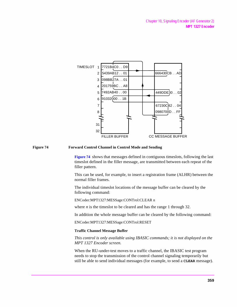
Chapter 10, Signaling Encoder (AF Generator 2)MPT 1327 Encoder
Figure 74 Forward Control Channel in Control Mode and Sending
Figure 74 shows that messages defined in contiguous timeslots, following the last timeslot defined in the filler message, are transmitted between each repeat of the filler pattern.
This can be used, for example, to insert a registration frame (ALHR) between the normal filler frames.
The individual timeslot locations of the message buffer can be cleared by the following command:
ENCoder:MPT1327:MESSage:CONTrol:CLEAR n
where n is the timeslot to be cleared and has the range 1 through 32.
In addition the whole message buffer can be cleared by the following command:
ENCoder:MPT1327:MESSage:CONTrol:RESET
Traffic Channel Message Buffer
This control is only available using IBASIC commands; it is not displayed on the MPT 1327 Encoder screen.
When the RU-under-test moves to a traffic channel, the IBASIC test program needs to stop the transmission of the control channel signaling temporarily but still be able to send individual messages (for example, to send a CLEAR message).
7492AB40 . . 00
5439AB12 . . 01
FILLER BUFFER CC MESSAGE BUFFER
TIMESLOT 1
2
3
4
5
6
7
8
31
32
666430CB . . AD
449DDE30 . . 02
67230CB2 . . 04
0980700D . . FF
201759BC . . A8
098BB27A . . 01
7721B4C0 . . D9
91032000 . . 1B
359
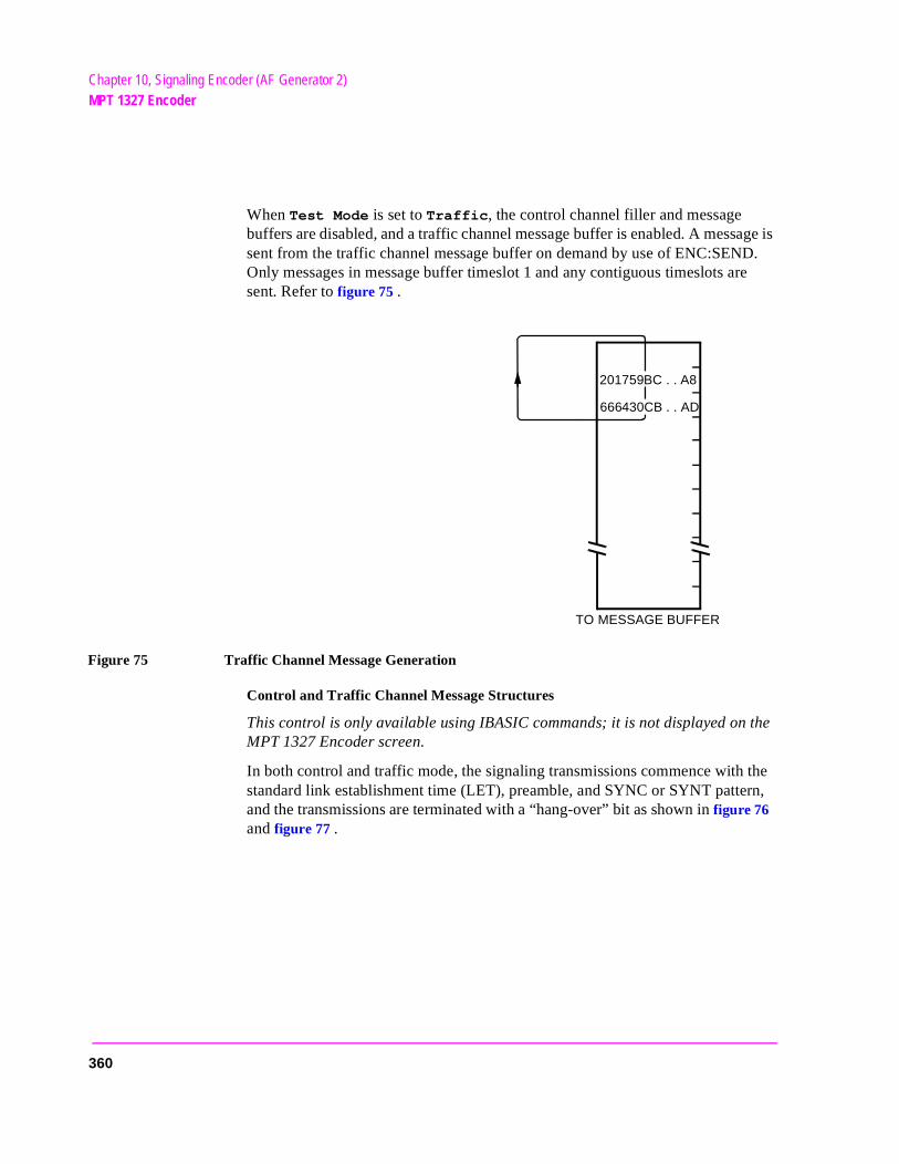
Chapter 10, Signaling Encoder (AF Generator 2)MPT 1327 Encoder
When Test Mode is set to Traffic, the control channel filler and message buffers are disabled, and a traffic channel message buffer is enabled. A message is sent from the traffic channel message buffer on demand by use of ENC:SEND. Only messages in message buffer timeslot 1 and any contiguous timeslots are sent. Refer to figure 75 .
Figure 75 Traffic Channel Message Generation
Control and Traffic Channel Message Structures
This control is only available using IBASIC commands; it is not displayed on the MPT 1327 Encoder screen.
In both control and traffic mode, the signaling transmissions commence with the standard link establishment time (LET), preamble, and SYNC or SYNT pattern, and the transmissions are terminated with a “hang-over” bit as shown in figure 76 and figure 77 .
TO MESSAGE BUFFER
666430CB . . AD
201759BC . . A8
360
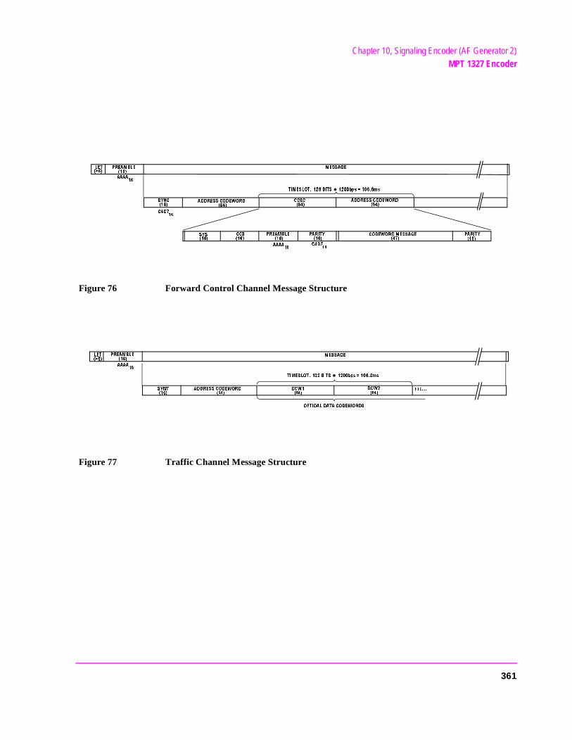
Chapter 10, Signaling Encoder (AF Generator 2)MPT 1327 Encoder
Figure 76 Forward Control Channel Message Structure
Figure 77 Traffic Channel Message Structure
,%4
02%!-",%
39.#
!$$2%33#/$%7/2$
-%33!'%
4)-%3,/4 ")43 BPSMS
!!!!
!$$2%33#/$%7/2$
#/$%7/2$-%33!'%
0!2)49
#$
393
##3
##3#
!!!!
0!2)49
02%!-",%
#$
/04)/!,$!4!#/$%7/2$3
!$$2%33#/$%7/2$
39.4
02%!-",%
,%4
!!!!
$#7
$#7 %4#
-%33!'%
4)-%3,/4 ")43 BPSMS
361
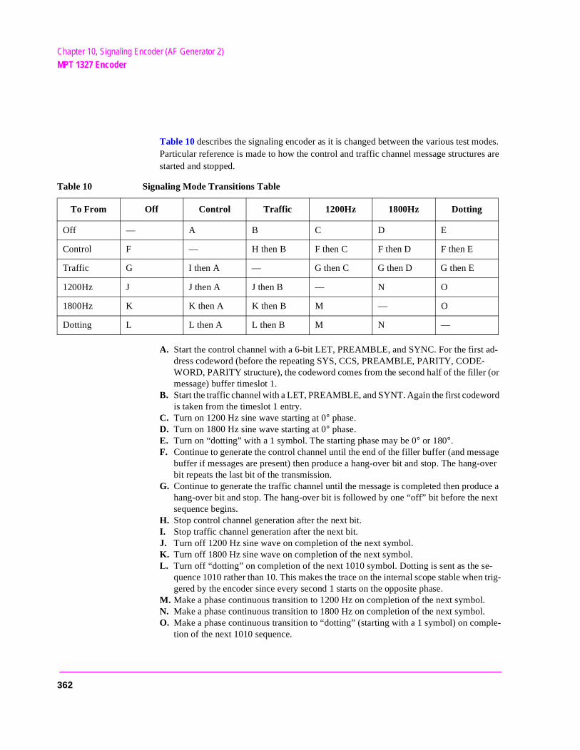
Chapter 10, Signaling Encoder (AF Generator 2)MPT 1327 Encoder
sage -over
uce a ext
e-en trig-
l. l. ple-
Table 10 describes the signaling encoder as it is changed between the various test modes. Particular reference is made to how the control and traffic channel message structures are started and stopped.
A. Start the control channel with a 6-bit LET, PREAMBLE, and SYNC. For the first ad-dress codeword (before the repeating SYS, CCS, PREAMBLE, PARITY, CODE-WORD, PARITY structure), the codeword comes from the second half of the filler (or message) buffer timeslot 1.
B. Start the traffic channel with a LET, PREAMBLE, and SYNT. Again the first codeword is taken from the timeslot 1 entry.
C. Turn on 1200 Hz sine wave starting at 0° phase. D. Turn on 1800 Hz sine wave starting at 0° phase. E. Turn on “dotting” with a 1 symbol. The starting phase may be 0° or 180°. F. Continue to generate the control channel until the end of the filler buffer (and mes
buffer if messages are present) then produce a hang-over bit and stop. The hangbit repeats the last bit of the transmission.
G. Continue to generate the traffic channel until the message is completed then prodhang-over bit and stop. The hang-over bit is followed by one “off” bit before the nsequence begins.
H. Stop control channel generation after the next bit. I. Stop traffic channel generation after the next bit. J. Turn off 1200 Hz sine wave on completion of the next symbol. K. Turn off 1800 Hz sine wave on completion of the next symbol. L. Turn off “dotting” on completion of the next 1010 symbol. Dotting is sent as the s
quence 1010 rather than 10. This makes the trace on the internal scope stable whgered by the encoder since every second 1 starts on the opposite phase.
M. Make a phase continuous transition to 1200 Hz on completion of the next symboN. Make a phase continuous transition to 1800 Hz on completion of the next symboO. Make a phase continuous transition to “dotting” (starting with a 1 symbol) on com
tion of the next 1010 sequence.
Table 10 Signaling Mode Transitions Table
To From Off Control Traffic 1200Hz 1800Hz Dotting
Off — A B C D E
Control F — H then B F then C F then D F then E
Traffic G I then A — G then C G then D G then E
1200Hz J J then A J then B — N O
1800Hz K K then A K then B M — O
Dotting L L then A L then B M N —
362

Chapter 10, Signaling Encoder (AF Generator 2)Using the MPT 1327 Encoder
Using the MPT 1327 Encoder
Manually Testing MPT 1327 Radios
MPT 1327 signals contain complex groupings of digital data that vary in format and function, depending on a number of system operating parameters.
To be able to test MPT 1327 radios using this screen, you must be familiar with the theory, applications, and specifications of the MPT 1327 system. You must also be familiar with IBASIC programming, since some of the required signaling commands are not available on the encoder screen; they must be sent using IBASIC commands. (See "Undisplayed Controls" on page 353.)
The large volume of information required to explain the MPT 1327 system is beyond the scope of this manual. Documents explaining the structure and specifications of this system should be obtained from the radio communications regulatory agency of the appropriate country.
System Identity
The System Identity uses two areas to enter the system identity number as either a decimal or hexadecimal value. When a value is entered in either field, the corresponding value is automatically entered in the other field.
The first field is a four-digit hexadecimal integer with leading zeros (H indicates the hexadecimal number base). It has the range 0 through 7FFF16 and its default is 000016.
The second field is a five-digit decimal integer with leading zeros. It has the range 0 through 32767 and its default is 00000.
It is essential that the 15-bit system identity transmitted by the Test Set matches the system identity programmed into the radio unit. If there is not a match, the RU will not recognize the forward control channel and no communication will be possible.
363

Chapter 10, Signaling Encoder (AF Generator 2)Using the MPT 1327 Encoder
nd
0
Radio Unit Under Test
The Radio Unit Under Test function uses two input fields; a 7-bit Prefix field and a 13-bit Ident field. This allows you to enter the prefix and identity of your radio unit (RU).
Each RU has a unique prefix/ident value that is used to address messages to that RU only. An RU can also have a number of “group” prefix/ident values that it aseveral other RUs respond to.
The prefix is a three-digit decimal integer with leading zeros. It has the rangethrough 127 and its default is 000.
The ident is a four-digit decimal integer with leading zeros. It has the range 0through 8191 and its default is 0001.
364
Chapter 10, Signaling Encoder (AF Generator 2)Using the MPT 1327 Encoder
e of
0
Simulated Calling Unit
The Simulated Calling Unit function uses two input fields; a 7-bit Prefix field and a 13-bit Ident field. This allows you to enter the prefix and identity of the calling unit.
To test an RU the Test Set simulates a Trunking System Controller (TSC). In some tests the Test Set simulates calls from a third party. For this purpose it is necessary to specify the simulated calling unit’s number.
The simulated calling party could be any radio or line unit. It could also be onthe special idents indicating, for example, a system wide call or a call from a PABX or PSTN gateway.
The prefix is a three-digit decimal integer with leading zeros. It has the rangethrough 127 and its default value is 000.
The ident is a four-digit decimal integer with leading zeros. It has the range 0through 8191 and its default value is 0002.
365
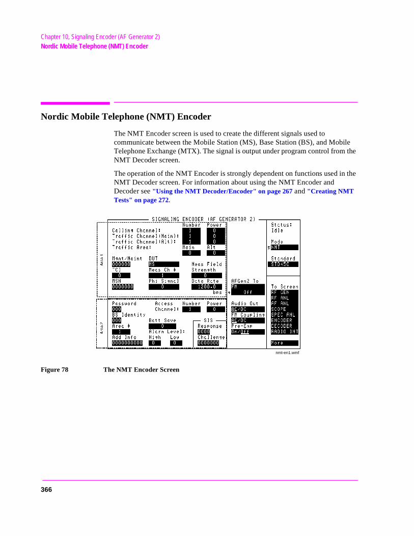
Chapter 10, Signaling Encoder (AF Generator 2)Nordic Mobile Telephone (NMT) Encoder
Nordic Mobile Telephone (NMT) Encoder
The NMT Encoder screen is used to create the different signals used to communicate between the Mobile Station (MS), Base Station (BS), and Mobile Telephone Exchange (MTX). The signal is output under program control from the NMT Decoder screen.
The operation of the NMT Encoder is strongly dependent on functions used in the NMT Decoder screen. For information about using the NMT Encoder and Decoder see "Using the NMT Decoder/Encoder" on page 267 and "Creating NMT Tests" on page 272.
Figure 78 The NMT Encoder Screen
nmt-en1.wmf
366
Chapter 10, Signaling Encoder (AF Generator 2)Nordic Mobile Telephone (NMT) Encoder
ing the
Access Channel Number
This field defines the channel number for the signal that initiates a call from the MS to the MTX.
Valid Entry Range: 1 through 2023
NMT Frames Affected: 3d, 3dTA2, 4b, 4bTA2, 10aAC
Operating Considerations
This field is only used with the STD900 standard.
This setting affects the RF generator and analyzer frequencies used when the TCHAN AC and RCHAN AC commands are used.
See Also
Calling Channel Number field description, on page 371
Access Channel Power
This channel’s power setting. Each power setting represents one of the four available levels allowed by the NMT standards.
Valid Entry Range: 0 through 3
NMT Frames Affected: 3d, 3dTA2, 4b, 4bTA2, 10aAC.
Operating Considerations
This field is only used with the STD900 standard.
Add Info
The additional information field contains various types of information, dependon the frame type. Several frame types contain additional information digits inform H1 to H10, as outlined in the NMT system standards.
The following table shows the relationship between the Add Info, %, and Bate Save fields, and how they are used in frame data. (The H1 to H10 designations correspond to the frame digit assignments shown in the NMT DOC. 900-1, Jan. 1985 standards.)
367
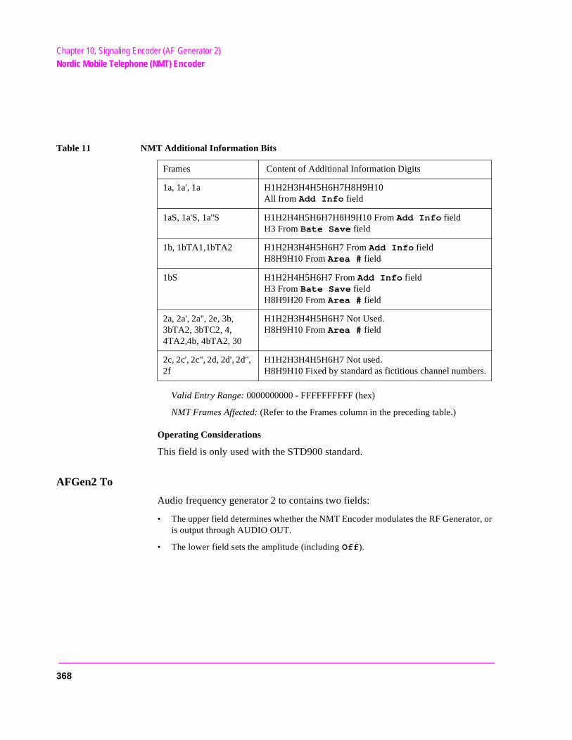
Chapter 10, Signaling Encoder (AF Generator 2)Nordic Mobile Telephone (NMT) Encoder
or, or
.
Valid Entry Range: 0000000000 - FFFFFFFFFF (hex)
NMT Frames Affected: (Refer to the Frames column in the preceding table.)
Operating Considerations
This field is only used with the STD900 standard.
AFGen2 To
Audio frequency generator 2 to contains two fields:
• The upper field determines whether the NMT Encoder modulates the RF Generatis output through AUDIO OUT.
• The lower field sets the amplitude (including Off).
Table 11 NMT Additional Information Bits
Frames Content of Additional Information Digits
1a, 1a', 1a H1H2H3H4H5H6H7H8H9H10All from Add Info field
1aS, 1a'S, 1a''S H1H2H4H5H6H7H8H9H10 From Add Info field H3 From Bate Save field
1b, 1bTA1,1bTA2 H1H2H3H4H5H6H7 From Add Info fieldH8H9H10 From Area # field
1bS H1H2H4H5H6H7 From Add Info fieldH3 From Bate Save field H8H9H20 From Area # field
2a, 2a', 2a'', 2e, 3b, 3bTA2, 3bTC2, 4, 4TA2,4b, 4bTA2, 30
H1H2H3H4H5H6H7 Not Used. H8H9H10 From Area # field
2c, 2c', 2c'', 2d, 2d', 2d'', 2f
H1H2H3H4H5H6H7 Not used.H8H9H10 Fixed by standard as fictitious channel numbers
368
Chapter 10, Signaling Encoder (AF Generator 2)Nordic Mobile Telephone (NMT) Encoder
larm
larm
e
Alarm Level Low
This field sets the lower trigger level for the signal-strength measurement’s afor the Phi signal.
Valid Entry Range: 0 through F (hex)
NMT Frames Affected: 20, 25.
Operating Considerations
This field is only used with the STD900 standard.
Alarm Level High
This field sets the upper trigger level for the signal-strength measurement’s afor the Phi signal.
Valid Entry Range: 0 through F (hex)
NMT Frames Affected: 20, 25.
Operating Considerations
This field is only used with the STD900 standard.
Area #
The area number field identifies which MTX is used to call an MS. This identification prevents MS to BS calling problems caused by co-channel interference.
Valid Entry Range: 1 through 4
NMT Frames Affected: 1b, 1bS, 1bTA1, 1bTA2, 2a, 2a’, 2a’’, 2e, 3bTA2, 3b, 3bTC2, 4, 4TA2, 4b, 4bTA2, 10a, 10aAC, 10b, 10c, 10d, 11a, 11b, 12, 30.
Operating Considerations
This information is used to encode the information in the last three digits of thAdd Info field, rather than taking the information directly from that field.
This field is only used with the STD900 standard.
369
Chapter 10, Signaling Encoder (AF Generator 2)Nordic Mobile Telephone (NMT) Encoder
Audio Out
Audio out coupling selects ac or dc coupling of the encoder to the AUDIO OUT connector when the upper AFGen2 To field is set to Audio Out.
BS Identity
The base station identity field provides the 3-digit hex code that identifies which BS an MTX is communicating with.
Valid Entry Range: 000 through FFF (hex)
NMT Frames Affected: 20, 21b, 21c, 22.
Operating Considerations
This field is only used with the STD900 standard.
Batt Save
The the length of the battery saving period in 5 second increments. For example, a setting of 5 produces a 25-second period.
Valid Entry Range: 0 through 7
NMT Frames Affected: 1aS, 1a’S, 1a’’S, 1bS
Operating Considerations
This field is only used with the STD900 standard.
370
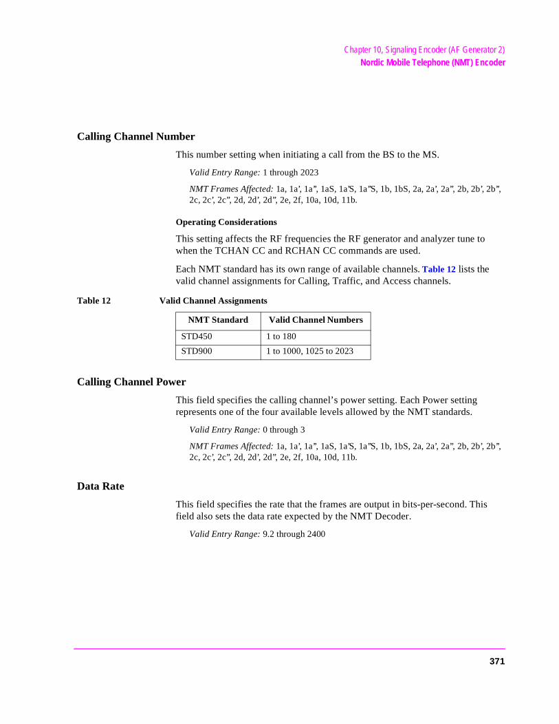
Chapter 10, Signaling Encoder (AF Generator 2)Nordic Mobile Telephone (NMT) Encoder
Calling Channel Number
This number setting when initiating a call from the BS to the MS.
Valid Entry Range: 1 through 2023
NMT Frames Affected: 1a, 1a’, 1a’’, 1aS, 1a’S, 1a’’S, 1b, 1bS, 2a, 2a’, 2a’’, 2b, 2b’, 2b’’, 2c, 2c’, 2c’’, 2d, 2d’, 2d’’, 2e, 2f, 10a, 10d, 11b.
Operating Considerations
This setting affects the RF frequencies the RF generator and analyzer tune to when the TCHAN CC and RCHAN CC commands are used.
Each NMT standard has its own range of available channels. Table 12 lists the valid channel assignments for Calling, Traffic, and Access channels.
Calling Channel Power
This field specifies the calling channel’s power setting. Each Power setting represents one of the four available levels allowed by the NMT standards.
Valid Entry Range: 0 through 3
NMT Frames Affected: 1a, 1a’, 1a’’, 1aS, 1a’S, 1a’’S, 1b, 1bS, 2a, 2a’, 2a’’, 2b, 2b’, 2b’’, 2c, 2c’, 2c’’, 2d, 2d’, 2d’’, 2e, 2f, 10a, 10d, 11b.
Data Rate
This field specifies the rate that the frames are output in bits-per-second. This field also sets the data rate expected by the NMT Decoder.
Valid Entry Range: 9.2 through 2400
Table 12 Valid Channel Assignments
NMT Standard Valid Channel Numbers
STD450 1 to 180
STD900 1 to 1000, 1025 to 2023
371
Chapter 10, Signaling Encoder (AF Generator 2)Nordic Mobile Telephone (NMT) Encoder
DUT
The device-under-test field defines the device you are testing.
Valid Entries: MS, BS, MTX
NMT Frames Affected: None
Operating Considerations
This field affects the RF generator and analyzer frequencies used for the NMT TCHAN and RCHAN program commands.
This field also affects how frames are interpreted by the decoder when determining the type of frame being received.
FM Coupling
This field alters the FM modulator to allow DCFM from internal and external modulation sources. This field also selects ac or dc coupling between the RF Generator’s frequency modulator and the rear-panel MODULATION INPUT connector.
Meas Ch #
The measurement channel number field specifies the channel whose signal strength is measured.
Valid Entry Range: 1 through 2023
NMT Frames Affected: 21b, 21c, 26.
See Also
Calling Channel Number field description, on page 371
372
Chapter 10, Signaling Encoder (AF Generator 2)Nordic Mobile Telephone (NMT) Encoder
Meas Field Strength
This field specifies the Phi Signal strength measurement that is sent from the BS to the MTX.
Valid Entry Range: 0 through 99
NMT Frames Affected: 26
Mgmt/Maint
The management/maintenance field is used to send system status information.
Valid Entry Range: 000000 through FFFFFF (hex)
NMT Frames Affected: 22, 27, 28.
MSN
The mobile subscriber number field specifies the unique seven-digit code that identifies an MS.
Valid Entry Range: 0000000 through FFFFFFF (hex)
NMT Frames Affected: 2a, 2a’, 2a’’, 2b, 2b’, 2b’’, 2c, 2c’, 2c’’, 2d, 2d’, 2d’’, 2e, 2f, 3a1, 3a2, 3b, 3bTA2, 3bTC2, 3c, 3d, 3dTA2, 5a, 5b, 10a, 10aAC, 10b, 10c, 10d, 11, 11a, 11b, 12, 13a, 13b, 14a, 14b.
Phi Signal
This field specifies the F (Phi) signal frequency.
Valid Entry Range: 0 through F (hex)
NMT Frames Affected: 20, 21b, 21c, 25, 26.
373
Chapter 10, Signaling Encoder (AF Generator 2)Nordic Mobile Telephone (NMT) Encoder
r’s
Password
This field specifies the 3-digit code added to the end of the MSN to prevent unauthorized use of a subscriber number.
Valid Entry Range: 000 through FFF (hex)
NMT Frames Affected: 10b, 10c, 11a, 12.
Operating Considerations
This field is only used with the STD900 standard.
Pre-Emp
Pre-emphasis, when used, attenuates the lower frequency tone (1200 Hz at 1200 bps) to 2/3 of the field level setting.
SIS Challenge
The subscriber identity security challenge field is used to confirm a subscribeMS identity.
Valid Entry Range: 0000000 through FFFFFFF (hex)
NMT Frame Affected: 7
Operating Considerations
This field is only used with the STD900 standard.
SIS Response
The subscriber identity security response field is used to respond to the SIS challenge to confirm a subscriber’s MS identity.
Valid Entry Range: 0000 through FFFF (hex)
NMT Frame Affected: 16
Operating Considerations
This field is only used with the STD900 standard.
374

Chapter 10, Signaling Encoder (AF Generator 2)Nordic Mobile Telephone (NMT) Encoder
ing
Standard
This NMT system standard for equipment you are testing. When a standard is chosen, the Test Set automatically alters several corresponding parameters.
Operating Considerations
Each standard affects the following conditions:
• The types of frames that can be sent.
• The range of valid channel numbers.
• The encoding of the frame data.
• The frequencies tuned to for the various channel settings when CHAN programmcommands are executed in an NMT program.
• The interpretation of received frames.
The following standards are available:
STD450: Transmit and receive frequencies are in the 453 to 467.5 MHz range.
STD900: Transmit and receive frequencies are in the 890 to 960 MHz range.
See Also
Calling Channel Number field description, on page 371
TCI
The tariff class information field is used to specify MS billing information to the MTX.
Valid Entry Range: 0 through 99
NMT Frames Affected: 5b, 13b.
Traffic Area - Alt
This field specifies the alternate traffic area code that identifies the base stations used to simultaneously transmit a calling signal to an MS.
Valid Entry Range: 0 through FF (hex)
NMT Frames Affected: 1bTA2, 3bTA2, 3dTA2, 4TA2, 4bTA2.
375
Chapter 10, Signaling Encoder (AF Generator 2)Nordic Mobile Telephone (NMT) Encoder
Traffic Area - Main
This field specifies the main traffic area code that identifies the base stations used to simultaneously transmit a calling signal to an MS.
Valid Entry Range: 0 through FF (hex)
NMT Frames Affected: 1a, 1a’, 1a’’, 1aS, 1a’S, 1a’’S, 1b, 1bS, 1bTA1, 2a, 2a’, 2a’’, 2b, 2b’, 2b’’, 2c, 2c’, 2c’’, 2d, 2d’, 2d’’, 2e, 2f, 3a1, 3a2, 3b, 3bTC2, 3c, 3d, 4, 4b, 5a, 5b, 7, 10a, 10aAC, 10b, 10c, 10d, 11a, 11b, 12, 20, 21b, 21c, 22, 30.
Traffic Channel (Alt) Number
This field specifies the alternate traffic channel used for conversation after communications have been established.
Valid Entry Range: 1 through 2023
NMT Frames Affected: 3a2, 3bTC2, 3c.
Operating Considerations
This setting affects the RF generator and analyzer frequencies used when the TCHAN TC2 and RCHAN TC2, or TCHAN TCA and RCHAN TCA, programming commands are used.
See Also
Calling Channel Number field description, on page 371
Traffic Channel (Alt) Power
This field specifies the power of the alternate traffic channel. Each power setting represents one of the four available levels allowed by the NMT standards.
Valid Entry Range: 0 through 3
NMT Frames Affected: 3a2, 3bTC2, 3c.
376
Chapter 10, Signaling Encoder (AF Generator 2)Nordic Mobile Telephone (NMT) Encoder
Traffic Channel (Main) Number
This field specifies the main traffic channel used for conversation after communications have been established.
Valid Entry Range: 1 through 2023
NMT Frames Affected: 1bTA1, 1bTA2, 2b, 2b’, 2b’’, 3a1, 3a2, 3b, 3bTA2, 3d, 3dTA2, 4, 4TA2, 5a, 5b, 7, 10b, 10c, 11, 11a, 12, 13a, 13b, 14a, 14b, 16, 20, 21b, 21C, 22, 25, 26, 27, 28, 30.
Operating Considerations
This setting affects the RF generator and analyzer frequencies used when the TCHAN TC1 and RCHAN TC1, or TCHAN TCM and RCHAN TCM, programming commands is used.
See Also
Calling Channel Number field description, on page 371
Traffic Channel (Main) Power
This field specifies the power of the main traffic channel. Each power setting represents one of the four available levels allowed by the NMT standards.
Valid Entry Range: 0 through 3
NMT Frames Affected: 1bTA1, 1bTA2, 2b, 2b’, 2b’’, 3a1, 3a2, 3b, 3bTA2, 3d, 3dTA2, 4, 4TA2, 5a, 5b, 7, 10b, 10c, 11, 11a, 12, 13a, 13b, 14a, 14b, 16, 20, 21b, 21c, 22, 25, 26, 27, 28, 30.
377
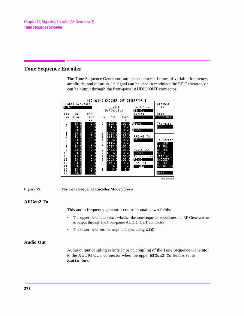
Chapter 10, Signaling Encoder (AF Generator 2)Tone Sequence Encoder
tor or
Tone Sequence Encoder
The Tone Sequence Generator outputs sequences of tones of variable frequency, amplitude, and duration. Its signal can be used to modulate the RF Generator, or can be output through the front-panel AUDIO OUT connector.
Figure 79 The Tone Sequence Encoder Mode Screen
AFGen2 To
This audio frequency generator control contains two fields:
• The upper field determines whether the tone sequence modulates the RF Generais output through the front-panel AUDIO OUT connector.
• The lower field sets the amplitude (including Off).
Audio Out
Audio output coupling selects ac or dc coupling of the Tone Sequence Generator to the AUDIO OUT connector when the upper AFGen2 To field is set toAudio Out.
tone-ec.wmf
378
Chapter 10, Signaling Encoder (AF Generator 2)Tone Sequence Encoder
s
Bursts
This field defines the number of sequences output each time Send is selected. This function works only when the Send Mode field is set to Burst.
FM Coupling
This field alters the FM modulator to allow DCFM from internal and external modulation sources. This field also selects ac or dc coupling between the RF Generator’s frequency modulator and the rear-panel MODULATION INPUT connector.
Pre-Emp
This field determines whether the encoder signal passes through or bypasse750 ms pre-emphasis.
Send
Selecting this field causes the tone sequence to be output.
Send Mode
This field selects the output format used when Send is selected to output a sequence.
• Single outputs the entire sequence once.
• Burst outputs the sequence the number of times specified in the Bursts field.
• Cont causes the sequence to be output continuously until Stop is selected.
• Step allows you to output the sequence one tone at a time by pressing Send for each tone.
Standard
This field selects the Tone Sequence standard for your radio.
Stop
Selecting this field stops the sequence being output.
379
Chapter 10, Signaling Encoder (AF Generator 2)Tone Sequence Encoder
e
ency g
f the
one
ins
e
Symbol Definition
This table specifies three types of information:
• Sym, symbol numbers, indicate the hexadecimal number that represents each tonwhen creating a tone sequence. These numbers cannot be changed.
• Freq Hz lists the tone frequency associated with each symbol number. The frequvalues are preset for the Standard you are using. You can change the values usinthe DATA keys.
• lists the relative amplitude for each tone. Amplitude is based on a percentage olevel shown in the AFGen2 To field.
Symbol Sequence
This area performs two functions:
• The Symbol Sequence field at the top of the screen is used to enter and edit the tsequence. The sequence uses the symbol numbers (Sym) listed in the Symbol Def-inition table. A total of 16 symbols can be entered.
• Below the Symbol Sequence is the sequence on/off times table. This table contathree entries:
Seq Num identifies which position in the Symbol Sequence is affected by the On and Off times listed.
On Time specifies the length of time a tone is output during the sequence.
Off Time specifies the length of time a tone is off before the next tone in thsequence is output.
Operating Considerations
The symbol numbers can be entered directly, using the DATA keys, or by using the Choices menu that appears when this field is selected. The Choices menu is also used to edit an existing sequence.
The on and off times are changed using the DATA keys.
380
11
Help Screen
381
Chapter 11, Help ScreenField Descriptions
Field Descriptions
The HELP screen is used to access tutorial information for a wide variety of instrument functions.
After this screen is accessed, push the cursor-control knob to display the help Index. The knob is then used to select the desired topic.
Once you have accessed the desired information, you can return to the Help Index by pushing the cursor-control knob.
To exit the HELP screen and return to the previous screen, press the PREV key.
382
12
I/O Configure Screen
383
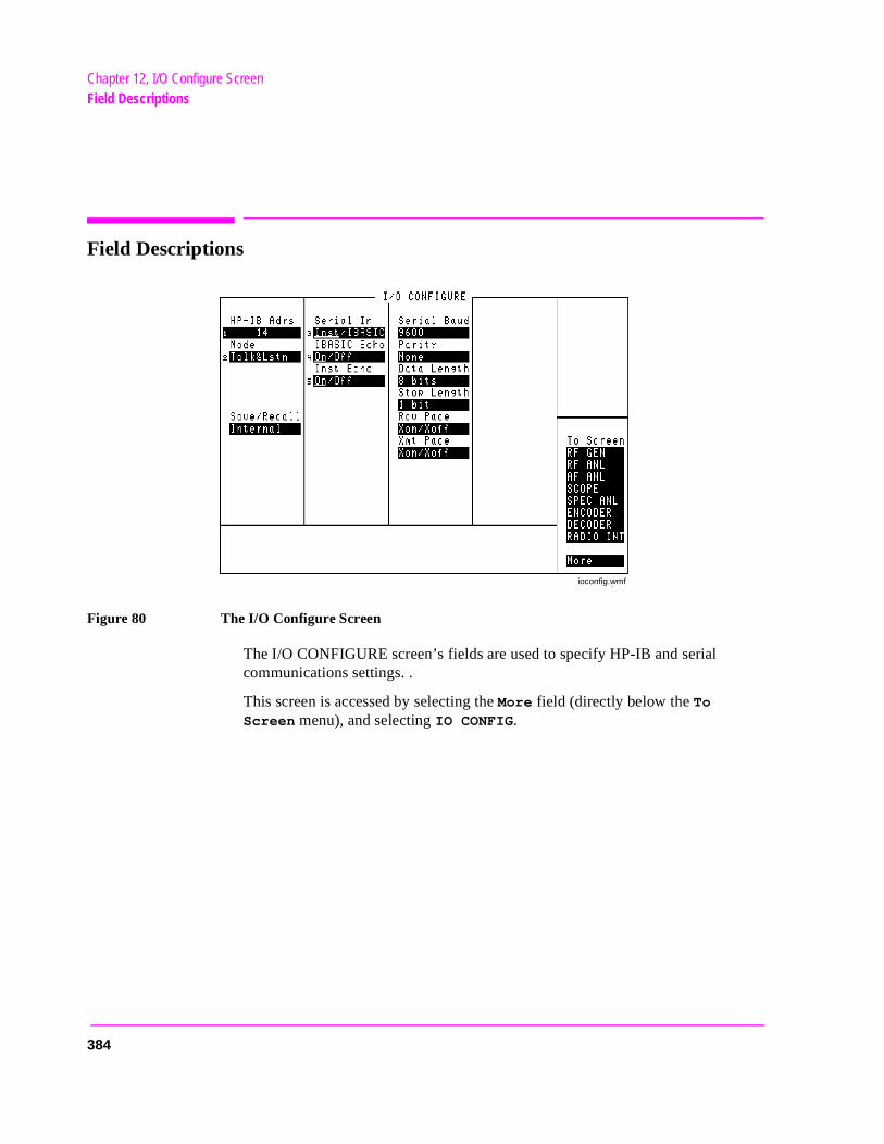
Chapter 12, I/O Configure ScreenField Descriptions
Field Descriptions
Figure 80 The I/O Configure Screen
The I/O CONFIGURE screen’s fields are used to specify HP-IB and serial communications settings. .
This screen is accessed by selecting the More field (directly below the To Screen menu), and selecting IO CONFIG.
ioconfig.wmf
384
Chapter 12, I/O Configure ScreenField Descriptions
Data Length
This field specifies the number of bits used for each word of serial data when using the rear-panel serial port.
This setting is retained when the instrument is turned off.
HP-IB Address
This field is used to display and change the HP-IB address of the Test Set.
Operating Considerations
The address can be set from 0 to 30 by using the DATA keys, or by pushing and then turning the cursor-control knob.
This setting is retained when the instrument is turned off.
IBASIC Echo
This field enables/disables screen and error message echoing from IBASIC.
This setting is retained when the instrument is turned off.
Inst Echo
This field enables/disables character and screen echoing when using an external ASCII RS-232 terminal or computer to enter or edit IBASIC programs.
This setting is retained when the instrument is turned off.
385

Chapter 12, I/O Configure ScreenField Descriptions
et.
ar-
ata
Mode
This field sets the HP-IB operating mode. Talk&Lstn is used for “normal” HP-IB operation. Control is used to control external instruments using the Test S
This setting is retained when the instrument is turned off.
Parity
This field specifies the serial communication parity setting when using the repanel serial port.
This setting is retained when the instrument is turned off.
Rcv Pace
The receive pace field is used when receiving serial data.
• Xon/Xoff lets the Test Set “talk” to the transmitting device to alter the rate of the dbeing sent.
• None disables the Xon/Xoff function.
This setting is retained when the instrument is turned off.
386
Chapter 12, I/O Configure ScreenField Descriptions
m is
hen
ing
disk
.
Save/Recall
This field specifies which memory device the Test Set accesses when the save and recall functions are used.
• Internal is a section of internal RAM. RAM is also used for running IBASIC programs, which may require you to delete the Save/Recall registers if the progravery large.
• Card is the front-panel MEMORY CARD slot. A Save/Recall Device is not Present message is displayed if you try to save or recall an instrument setup wa write-able memory card is not installed in the Test Set.
• RAM refers to RAM disks that you can create on internal RAM. Refer to the Programmer’s Guide for information on creating RAM Disks. This is part of the same memory used when “internal” is specified, and may have to be erased when loadvery large IBASIC programs. A Save/Recall Device is not initialized message is displayed if you try to save or recall an instrument setup when a RAMhas not been created.
• Disk is used with external disk drives. The Mode field must be set to Control to access the drive. Also, the HP-IB address of the drive must be entered in the External Disk Specification field of the TESTS (External Devices) screen
Serial Baud
This field selects the baud rate for serial communications when using the rear-panel serial port. Selecting this field displays a list of baud rate choices.
This setting is maintained after the instrument is turned off.
387
Chapter 12, I/O Configure ScreenField Descriptions
uter
am
hen
ata
Serial In
This field selects the destination of characters received by the Test Set on the serial port.
• Inst configures the serial port to connect to an external ASCII terminal or compto enter IBASIC programs, or to control the Test Set using an external keyboard.
• IBASIC is used to allow the IBASIC controller to read the serial port while a progris running.
Operating Considerations
If a serial printer is connected, the PRINT command causes the printer to take control of the serial port until printing is done.
This setting is maintained after the instrument is turned off.
See Also
Programmer’s Guide
Stop Length
This field specifies the number of stop bits used for serial communications wusing the rear-panel serial port. Selecting this field displays a list of stop bit choices.
This setting is maintained after the instrument is turned off.
Xmt Pace
The transmit pace field is used when transmitting serial data.
• Xon/Xoff lets the receiving device “talk” to the Test Set to alter the rate of the dbeing sent.
• None disables the Xon/Xoff function.
This setting is maintained after the instrument is turned off.
388

13
Message Screen
389

Chapter 13, Message ScreenField Descriptions
Field Descriptions
The MESSAGE screen lists any error or operation messages that have occurred since the instrument was turned on.
The type of error and the time it occurred are listed. If one error occurs more than once before a different error is encountered, the number of times it occurred, and when it occurred, are displayed.
All messages are shown until the entire display is filled. If enough errors occur, the MESSAGE screen will scroll the first messages past the top of the screen. These messages cannot be retrieved.
390
14
Oscilloscope Screen
391
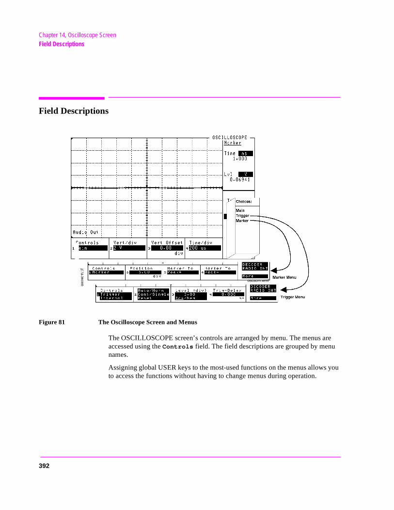
Chapter 14, Oscilloscope ScreenField Descriptions
you
Field Descriptions
Figure 81 The Oscilloscope Screen and Menus
The OSCILLOSCOPE screen’s controls are arranged by menu. The menus are accessed using the Controls field. The field descriptions are grouped by menunames.
Assigning global USER keys to the most-used functions on the menus allowsto access the functions without having to change menus during operation.
oscscrn.wmf
392
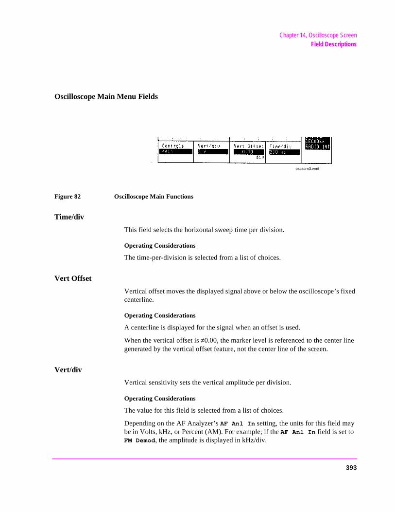
Chapter 14, Oscilloscope ScreenField Descriptions
ixed
Oscilloscope Main Menu Fields
Figure 82 Oscilloscope Main Functions
Time/div
This field selects the horizontal sweep time per division.
Operating Considerations
The time-per-division is selected from a list of choices.
Vert Offset
Vertical offset moves the displayed signal above or below the oscilloscope’s fcenterline.
Operating Considerations
A centerline is displayed for the signal when an offset is used.
When the vertical offset is ≠0.00, the marker level is referenced to the center line generated by the vertical offset feature, not the center line of the screen.
Vert/div
Vertical sensitivity sets the vertical amplitude per division.
Operating Considerations
The value for this field is selected from a list of choices.
Depending on the AF Analyzer’s AF Anl In setting, the units for this field may be in Volts, kHz, or Percent (AM). For example; if the AF Anl In field is set to FM Demod, the amplitude is displayed in kHz/div.
oscscrn3.wmf
393
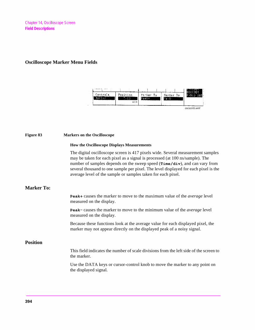
Chapter 14, Oscilloscope ScreenField Descriptions
Oscilloscope Marker Menu Fields
Figure 83 Markers on the Oscilloscope
How the Oscilloscope Displays Measurements
The digital oscilloscope screen is 417 pixels wide. Several measurement samples may be taken for each pixel as a signal is processed (at 100 ns/sample). The number of samples depends on the sweep speed (Time/div), and can vary from several thousand to one sample per pixel. The level displayed for each pixel is the average level of the sample or samples taken for each pixel.
Marker To:
Peak+ causes the marker to move to the maximum value of the average level measured on the display.
Peak− causes the marker to move to the minimum value of the average level measured on the display.
Because these functions look at the average value for each displayed pixel, the marker may not appear directly on the displayed peak of a noisy signal.
Position
This field indicates the number of scale divisions from the left side of the screen to the marker.
Use the DATA keys or cursor-control knob to move the marker to any point on the displayed signal.
oscscrn5.wmf
394
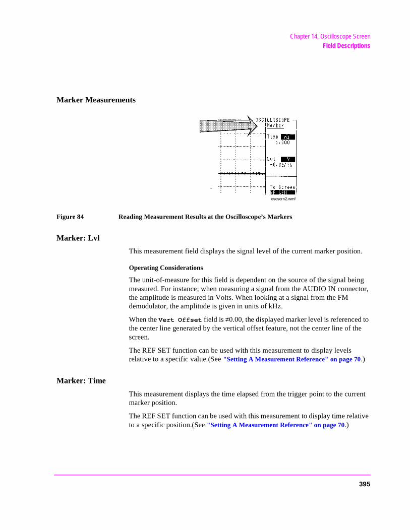
Chapter 14, Oscilloscope ScreenField Descriptions
Marker Measurements
Figure 84 Reading Measurement Results at the Oscilloscope’s Markers
Marker: Lvl
This measurement field displays the signal level of the current marker position.
Operating Considerations
The unit-of-measure for this field is dependent on the source of the signal being measured. For instance; when measuring a signal from the AUDIO IN connector, the amplitude is measured in Volts. When looking at a signal from the FM demodulator, the amplitude is given in units of kHz.
When the Vert Offset field is ≠0.00, the displayed marker level is referenced to the center line generated by the vertical offset feature, not the center line of the screen.
The REF SET function can be used with this measurement to display levels relative to a specific value.(See "Setting A Measurement Reference" on page 70.)
Marker: Time
This measurement displays the time elapsed from the trigger point to the current marker position.
The REF SET function can be used with this measurement to display time relative to a specific position.(See "Setting A Measurement Reference" on page 70.)
oscscrn2.wmf
395
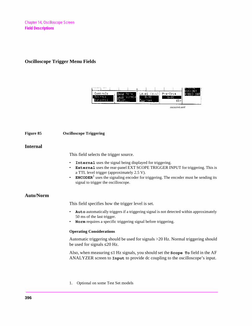
Chapter 14, Oscilloscope ScreenField Descriptions
is
g its
ely
.
Oscilloscope Trigger Menu Fields
Figure 85 Oscilloscope Triggering
Internal
This field selects the trigger source.
• Internal uses the signal being displayed for triggering. • External uses the rear-panel EXT SCOPE TRIGGER INPUT for triggering. This
a TTL level trigger (approximately 2.5 V). • ENCODER1 uses the signaling encoder for triggering. The encoder must be sendin
signal to trigger the oscilloscope.
1. Optional on some Test Set models
Auto/Norm
This field specifies how the trigger level is set.
• Auto automatically triggers if a triggering signal is not detected within approximat50 ms of the last trigger.
• Norm requires a specific triggering signal before triggering.
Operating Considerations
Automatic triggering should be used for signals >20 Hz. Normal triggering should be used for signals ≤20 Hz.
Also, when measuring ≤1 Hz signals, you should set the Scope To field in the AF ANALYZER screen to Input to provide dc coupling to the oscilloscope’s input
oscscrn4.wmf
396

Chapter 14, Oscilloscope ScreenField Descriptions
Cont/Single
This field specifies whether the oscilloscope is continuously triggered (Cont), or if it is only triggered each time Reset is selected (Single).
Level (div)
This control is divided into two fields:
The upper field (0.00) sets the internal trigger level as a function of vertical divisions. The trigger level is indicated by small pointers that appear on each side of the screen (only used for internal triggering).
The lower field (Pos/Neg) specifies whether triggering happens when the waveform being measured is positive-going (Pos), or negative-going (Neg).
Pre-Trig
This field specifies the number of horizontal divisions displayed previous to the trigger point. It allows you to see what the signal looked like before the trigger point.
When pre-triggering is used, the trigger point is indicated by small pointers that appear at the top and bottom of the screen.
Reset
See the Cont/Single field description, on page 397
397
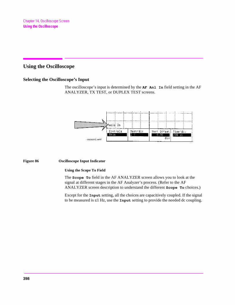
Chapter 14, Oscilloscope ScreenUsing the Oscilloscope
al .
Using the Oscilloscope
Selecting the Oscilloscope’s Input
The oscilloscope’s input is determined by the AF Anl In field setting in the AF ANALYZER, TX TEST, or DUPLEX TEST screens.
Figure 86 Oscilloscope Input Indicator
Using the Scope To Field
The Scope To field in the AF ANALYZER screen allows you to look at the signal at different stages in the AF Analyzer’s process. (Refer to the AF ANALYZER screen description to understand the different Scope To choices.)
Except for the Input setting, all the choices are capacitively coupled. If the signto be measured is ≤1 Hz, use the Input setting to provide the needed dc coupling
oscscrn1.wmf
398
15
a
Print Configure Screen
This screen configures the Test Set to print screen images with your printer. Images are printed using either the front-panel PRINT function (see “PrintingScreen” in volume 1) or the Print All USER key available on some TESTS environment screens.
Refer to your HP 11807 software manual for information on how to use your printer to print automated test results.
399
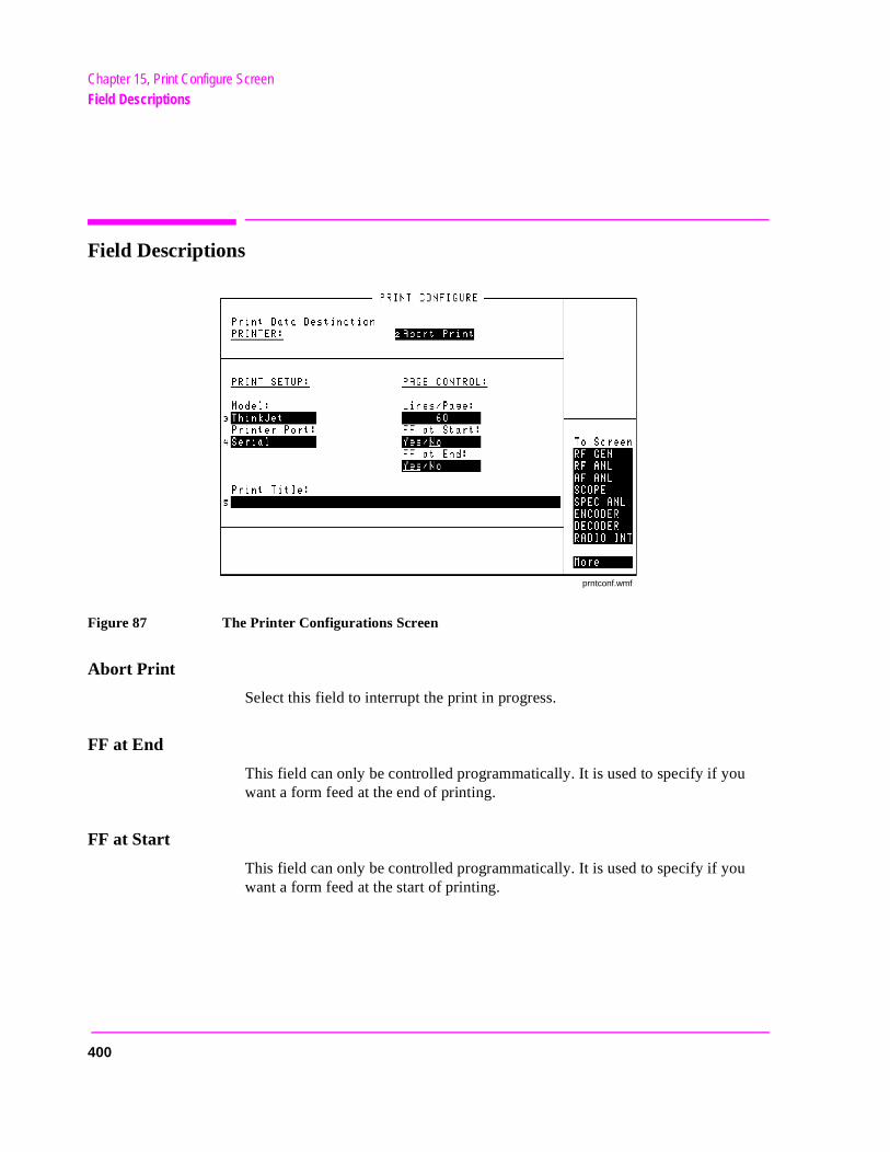
Chapter 15, Print Configure ScreenField Descriptions
Field Descriptions
Figure 87 The Printer Configurations Screen
Abort Print
Select this field to interrupt the print in progress.
FF at End
This field can only be controlled programmatically. It is used to specify if you want a form feed at the end of printing.
FF at Start
This field can only be controlled programmatically. It is used to specify if you want a form feed at the start of printing.
prntconf.wmf
400

Chapter 15, Print Configure ScreenField Descriptions
Lines/Page
This field is used to specify how many lines are printed per page.
Model
This field is used to specify the type of printer used. If your printer is not listed in the Choices menu when you select this field, configure your printer to emulate one of those that is listed.
Printer Address
This field is used to specify the address of an HP-IB printer. This field is only displayed if the Printer Port field is set to HP-IB.
Print Data Destination
This field will be used in the future to select whether the data is formatted specifically for printers or for some other device (such as a computer). At this time the only selection is Printer.
Printer Port
This field is used to select the port your printer is connected to.
Print Title
This field is used to enter up to 50 characters to be displayed at the top of the print.
401

Chapter 15, Print Configure ScreenField Descriptions
402
16
Radio Interface Screen
The RADIO INTERFACE screen controls the digital functions of the rear-panel RADIO INTERFACE parallel connector. A functional description of the radio interface, followed by field descriptions and operating instructions is included in this chapter.For more information see chapter 24, "Connector, Key, and Knob Descriptions" and the Programmer’s Guide.
403
Chapter 16, Radio Interface ScreenRadio Interface Functional Description
d
Data r
ctor ard. ata
Radio Interface Functional Description
Data I/O
The rear-panel connector labeled OPTION INTERFACE is present on Test Sets with a Radio Interface board. This connector has 16 pins that are used for parallel data transfer between an external device and the Test Set’s internal CPU.
The Radio Interface board includes 32 voltage comparators used for data input/output. Sixteen of the comparators have their outputs connected to the RadioInterface’s 16 parallel data pins, and 16 comparators have their inputs connecteto the Radio Interface’s 16 parallel data pins.
Data transfer is asynchronous, meaning that each block of data is transferred after a key is pressed on the Test Set’s front panel, or an HP-IB command is sent.transfer is also “half-duplex”, meaning that data input and output cannot occusimultaneously.
The parallel output data lines are implemented using 16 LM339M open-collevoltage comparators with pull-up resistors provided on the Radio Interface boThe Radio Interface provides two methods for determining the logic level for doutput:
1. Use the default (internal) power supply and internal pull-up resistors.
2. Use an external supply voltage connected to the internal pull-up resistors on the Radio Interface board.
These methods are described in "Setting the Radio Interface’s Logic Level" on page 409.
The parallel input data lines are implemented using another 16, LM339M, open-collector voltage comparators. An external supply voltage can be used to provide the reference voltage to the comparators if the default supply is not compatible with the external device-under-test.
This procedure is also described in "Setting the Radio Interface’s Logic Level" on page 409.
404
Chapter 16, Radio Interface ScreenRadio Interface Functional Description
ACE
gh a
n,
Audio Source
The Test Set has two audio sources, AFGen 1 and AFGen 2. Either or both of these sources can be routed to the OPTION INTERFACE connector. See "Audio Out" on page 520.
Audio Analyzer
The Test Set’s audio analyzer can be accessed through the OPTION INTERFconnector.
See "Audio Input" on page 520.
External Transmitter Key Relay
Two pins on the Radio Interface are connected in parallel with the Key Out 1 andKey Out 2 pins on the front-panel MIC/ACC connector.
The Key Out 1 and Key Out 2 pins allow a radio transmitter to be keyed throufront-panel display field called Ext TX Key. Refer to "Key Out 1" on page 520 and "Key Out 2" on page 520.
Interrupt Capability
Two pins on the Radio Interface are designated as Interrupt lines 1 and 2. If Interrupt 1 or 2 is armed, by selecting Arm on the RADIO INTERFACE screeand the corresponding pin is grounded, the word Tripped is displayed on the RADIO INTERFACE screen, and a status register bit is set.
Refer to "Interrupt Input 1" on page 521 and "Interrupt Input 2" on page 521.
+12.6 V, −12.6 V Supplies
The Radio Interface provides +12.6 V and −12.6 V power supplies capable of powering low-current devices.
Refer to "−12.6 V" on page 520, and "+12.6 V" on page 520.
Refer to "Using the Radio Interface (Manual Operation)" on page 409 and "Using The Radio Interface (Remote Operation)" on page 415 for more detailed information about using the Radio Interface.
405
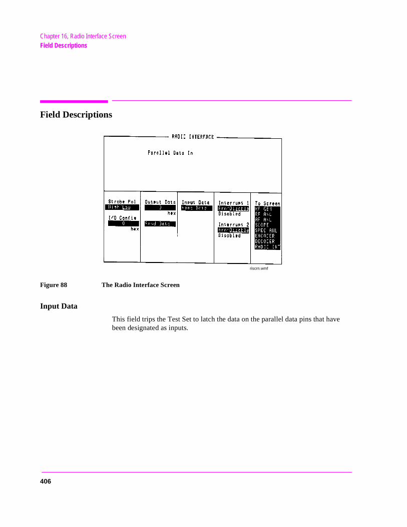
Chapter 16, Radio Interface ScreenField Descriptions
Field Descriptions
Figure 88 The Radio Interface Screen
Input Data
This field trips the Test Set to latch the data on the parallel data pins that have been designated as inputs.
riscrn.wmf
406
Chapter 16, Radio Interface ScreenField Descriptions
Interrupt 1
This field arms or disarms the Interrupt 1 pin. When it is armed, and the pin is pulled low by an external device, Tripped is displayed below the field until the interrupt is re-armed.
Operating Considerations
The field can be queried directly in an IBASIC or HP-IB program, or it can be monitored with the HP-IB status reporting system. This is done by reading bit 5 of the status byte and then reading bit 13 of the Hardware 1 status register. The Interrupt 1 pin can also be set as the HP-IB SRQ mask.
Once the interrupt has been tripped it must be re-armed. To do this, remove the low on the Interrupt 1 pin and then set the Interrupt 1 field to Disable and then set it to Arm .
Interrupts can be disabled and any external signals will have no effect on the interrupt.
Both Interrupt 1 and Interrupt 2 are independent, and they can be used simultaneously.
See also
Programmer’ Guide
Interrupt 2
Same as Interrupt 1 but, it applies to the Interrupt 2 pin on the RADIO INTERFACE connector and bit 14 of the Hardware 1 status register.
407
Chapter 16, Radio Interface ScreenField Descriptions
al, are 0FF.
FFF. t to
ized
ulse
I/O Config
This field designates which of the 16 parallel data pins will be used as inputs. Pins designated as inputs are pulled high internally. They can be left high for a logic 1 or pulled low for a logic 0.
Operating Considerations
A hexadecimal number that can range from 0000 to FFFF is entered in this field. Hex 0000 designates no pins as inputs, while hex FFFF designates all 16 pins as inputs.
To determine the number, convert the input pin’s binary weight to hexadecimthen add. Pin 19, D0, is the least significant bit. For example, if D0 through D7to be inputs and D8 through D15 are outputs the number to enter would be 0
Output Data
This field sets the data to be output on the parallel data lines.
Operating Considerations
The data is entered as a hexadecimal number that can range from 0000 to FTo determine the number, convert the binary weight of the pins that you wanset high to hexadecimal, then add. Pin 19, D0, is the least significant bit. Forexample 0008 would set pin 22, D3, high and the rest of the pins low.
The field will show the entered value but the pins don’t change until the Send
Data field is selected.
Parallel Data In
This field displays the value on the parallel data pins when the Parallel Data
In field is selected. The data appears in bitwise fashion with the 16 bits organfrom MSB to LSB.
Send Data
When selected, this field clocks the data in the Output Data field to the parallel data pins. It also outputs a pulse on the Strobe pin.
Strobe Pol
The strobe polarity field sets the polarity of the pulse on the Strobe pin. This poccurs when the Send Data field is selected.
408
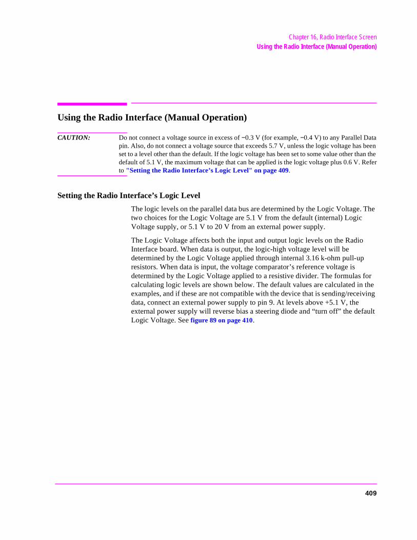
Chapter 16, Radio Interface ScreenUsing the Radio Interface (Manual Operation)
for the
Using the Radio Interface (Manual Operation)
CAUTION: Do not connect a voltage source in excess of −0.3 V (for example, −0.4 V) to any Parallel Datapin. Also, do not connect a voltage source that exceeds 5.7 V, unless the logic voltage has beenset to a level other than the default. If the logic voltage has been set to some value other than thedefault of 5.1 V, the maximum voltage that can be applied is the logic voltage plus 0.6 V. Referto "Setting the Radio Interface’s Logic Level" on page 409.
Setting the Radio Interface’s Logic Level
The logic levels on the parallel data bus are determined by the Logic Voltage. The two choices for the Logic Voltage are 5.1 V from the default (internal) Logic Voltage supply, or 5.1 V to 20 V from an external power supply.
The Logic Voltage affects both the input and output logic levels on the Radio Interface board. When data is output, the logic-high voltage level will be determined by the Logic Voltage applied through internal 3.16 k-ohm pull-up resistors. When data is input, the voltage comparator’s reference voltage is determined by the Logic Voltage applied to a resistive divider. The formulas calculating logic levels are shown below. The default values are calculated inexamples, and if these are not compatible with the device that is sending/receiving data, connect an external power supply to pin 9. At levels above +5.1 V, the external power supply will reverse bias a steering diode and “turn off” the default Logic Voltage. See figure 89 on page 410.
409
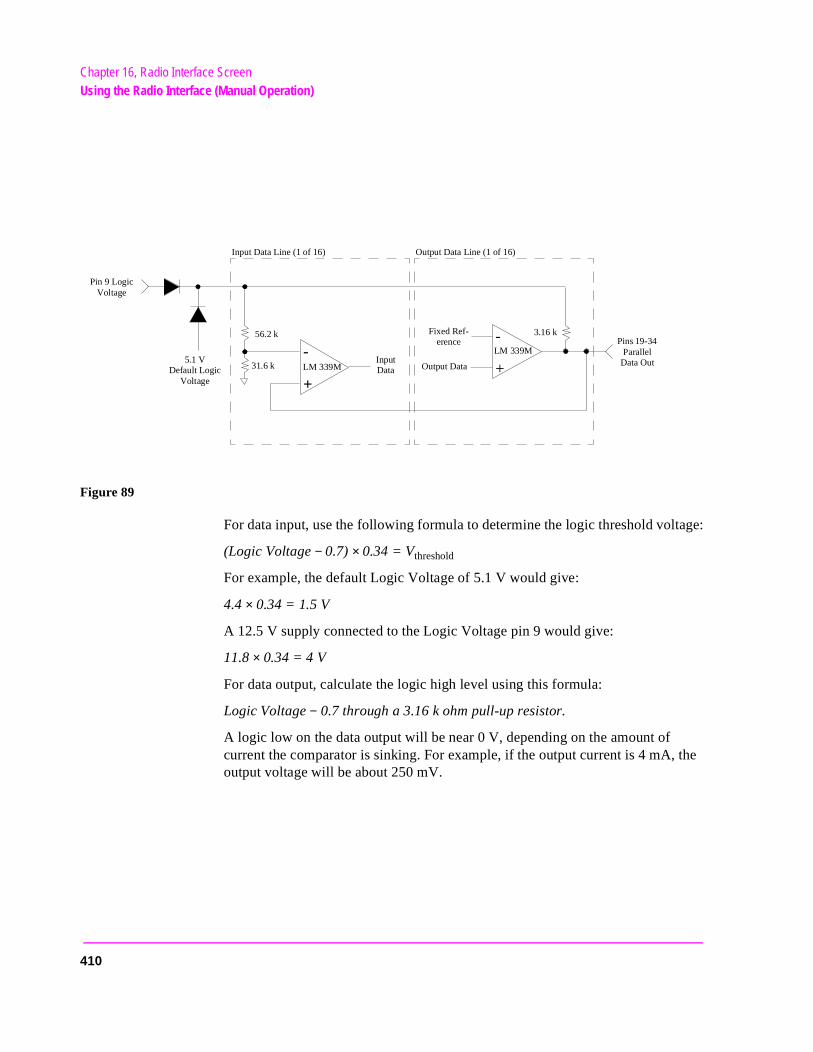
Chapter 16, Radio Interface ScreenUsing the Radio Interface (Manual Operation)
Figure 89
For data input, use the following formula to determine the logic threshold voltage:
(Logic Voltage − 0.7) × 0.34 = Vthreshold
For example, the default Logic Voltage of 5.1 V would give:
4.4 × 0.34 = 1.5 V
A 12.5 V supply connected to the Logic Voltage pin 9 would give:
11.8 × 0.34 = 4 V
For data output, calculate the logic high level using this formula:
Logic Voltage − 0.7 through a 3.16 k ohm pull-up resistor.
A logic low on the data output will be near 0 V, depending on the amount of current the comparator is sinking. For example, if the output current is 4 mA, the output voltage will be about 250 mV.
+
-+
-
31.6 k
56.2 k
LM 339M5.1 V
Default LogicVoltage
Pin 9 LogicVoltage
Input Data Output Data
Fixed Ref-erence
3.16 k
LM 339MPins 19-34
Parallel Data Out
Input Data Line (1 of 16) Output Data Line (1 of 16)
410
Chapter 16, Radio Interface ScreenUsing the Radio Interface (Manual Operation)
.
re d to
the ut a
is
e
Inputting Data
Data can only be input through parallel data bus lines that are configured as inputs. Data bus lines are configured as inputs by setting the output comparators to their logic-high states (positive output level). This is best accomplished by entering a hex value in the I/O Config field that will set the corresponding bit(s) to a 1. For example, if you want to use lines 0-7 for input and lines 8-15 for output, enter 00FF (which would be 0000000011111111 in binary) in the I/O Config field.
To read data to the Test Set’s internal CPU, select the Read Data field on the RADIO INTERFACE screen. A 16-bit binary value will be displayed under theParallel Data In field near the top of the screen.
Important: When data is read, the Parallel Data In field will display the value for all 16 parallel data bus lines, not just the lines designated as inputs
See the I/O Config field description, on page 408.
The need for configuring pins as inputs is a result of the “half-duplex” hardwaarchitecture of the bus. The 16 I/O pins on the parallel data bus are connecteboth the input data comparators and the output data comparators. Because output comparators are open-collector, a logic low makes it impossible to inplogic high, since the output transistor is essentially clamped to ground.
NOTE: A logic “OR” function is implemented in the Radio Interface design between I/O Config field and the Send Data the . Entering a hex value in the I/O Config field writes that value to the output data lines, just as selecting Send Datawrites the value entered in the Output Data field to the output data lines. The effect of thoperation is that it will not be possible to use the Output Data field to set a parallel databus line low if that line has been designated as an input by the value entered in thI/OConfig field.
The fastest rate at which input data can change is about 50 kHz. The practical limits on data transfer, however, are based on the speed of the IBASIC or external controller program since all data transfer is asynchronous.
411

Chapter 16, Radio Interface ScreenUsing the Radio Interface (Manual Operation)
tance. about ).
been
the ur at Pol for
Outputting Data
Outputting data is accomplished by entering the appropriate hex value in the Output Data field, and then selecting the Send Data field.
The output data value can be incremented or decremented by turning the cursor control knob with the Output Data field highlighted.
The output data lines are implemented by open-collector output voltage comparators. Sending a logic 0 causes active pull-down through a transistor in the voltage comparator. Sending a logic 1 causes passive pull-up through a pull-up resistor.
Variations in the Logic Voltage can be used to provide logic levels compatible with the radio-under-test. See "Setting the Radio Interface’s Logic Level" on page 409.
The data transfer rate for data output is primarily determined by the speed of the IBASIC or external program, not the ability of the Test Set’s internal CPU to access and output the data on the parallel lines, or the output loading capaci(If loading capacitance is below 158 pF, the Test Set’s CPU can send data at 200 Kb/s. The time for a program line to execute is typically greater than this
The Parallel Strobe Out, pin 13, can be used to signal when output data has clocked onto the parallel data bus. The front-panel RADIO INTERFACE screen allows the choice of strobe polarity through the Strobe Pol field. As with the parallel data outputs, the Parallel Strobe Out logic threshold is determined byLogic Voltage. Although the edges of Parallel Strobe Out and data output occapproximately the same time, an external device should latch on the Strobe trailing edge, or better yet, the Strobe Pol level. This will allow sufficient time output data to settle. Refer to figure 90 on page 413
412
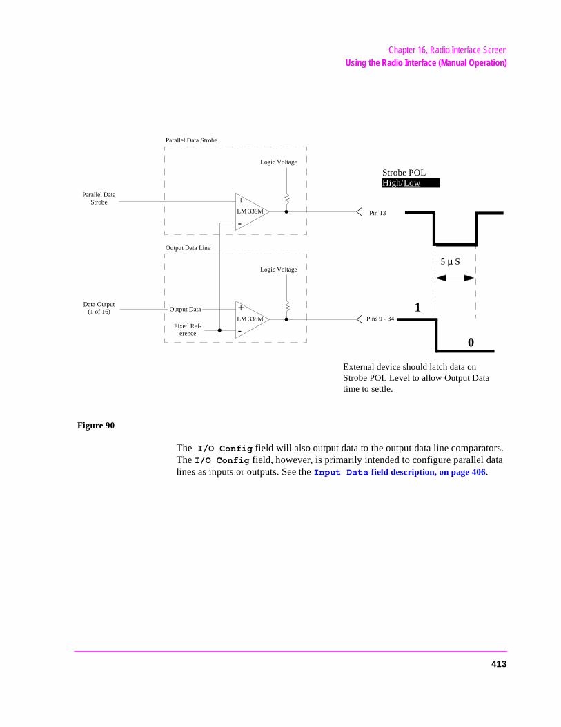
Chapter 16, Radio Interface ScreenUsing the Radio Interface (Manual Operation)
Figure 90
The I/O Config field will also output data to the output data line comparators. The I/O Config field, however, is primarily intended to configure parallel data lines as inputs or outputs. See the Input Data field description, on page 406.
+
-
Parallel Data Strobe
Logic Voltage
LM 339M
Parallel Data Strobe
+
-
Output Data
Fixed Ref-erence
Logic Voltage
LM 339M
Output Data Line
Data Output (1 of 16) 1
0
Strobe POLHigh/Low
External device should latch data on Strobe POL Level to allow Output Data time to settle.
Pin 13
Pins 9 - 34
5 µ S
413

Chapter 16, Radio Interface ScreenUsing the Radio Interface (Manual Operation)
rrupts
Using Interrupts
There are two interrupt lines that, when armed, allow monitoring of interrupt conditions. An interrupt is tripped when a logic low, determined by the same Logic Voltage as described in "Setting the Radio Interface’s Logic Level" on page 409, is detected. When tripped, the field directly below Arm/Disable will change from Armed to Tripped. To re-arm the next interrupt you must first disable the interrupt, then select Arm.
Besides displaying the word Tripped, an interrupt condition will set a bit in one of the Test Set’s status registers. This makes it possible to generate SRQ inteor query a condition register to find out if an interrupt has occurred. Refer to "Using The Radio Interface (Remote Operation)" on page 415.
414
Chapter 16, Radio Interface ScreenUsing The Radio Interface (Remote Operation)
nder
ata
et’s
, the at ed
Using The Radio Interface (Remote Operation)
CAUTION: Do not connect a voltage source in excess of −0.3 V (for example, −0.4 V) to any Parallel Datapin. Also, do not connect a voltage source that exceeds 5.7 V, unless the logic voltage has beenset to a level other than the default. If the logic voltage has been set to some value other than thedefault of 5.1 V, the maximum voltage that can be applied is the logic voltage plus 0.6 V. Referto "Setting the Radio Interface’s Logic Level" on page 409.
HP-IB Command Summary
The HP-IB command mnemonics can be found in the Programmer’s Guide, uRadio Interface.
Inputting Data over HP-IB
Use the following commands to configure the eight least significant parallel dbus lines as inputs by writing logic 1’s to them.
DISP RINT;RINTerface:PARallel:CONFigure #HFF (hex)
or
DISP RINT;RINTerface:PARallel:CONFigure 255 (decimal)
Use the following command to read the data on the parallel bus to the Test Sinternal CPU.
DISP RINT;RINTerface:PARallel:INPut:READ
Use the following command to query the data read by the READ command.
DISP RINT;RINTerface:PARallel:INPut:DATA?
If the output data lines are zero, and none of the input data lines are pulled lowvalue returned by the previous command will be 255 (decimal). Remember thdata lines not configured as inputs will still be displayed, and the value returnwill be the previous query will include all 16 data lines, some of which may beconfigured as outputs.
415

Chapter 16, Radio Interface ScreenUsing The Radio Interface (Remote Operation)
on
Outputting Data over HP-IB
Use one of the following commands to output 1’s to the 8 most significant bitsthe parallel data bus.
DISP RINT;RINTerface:PARallel:OUTPut 65280 ;SEND (decimal)
or
DISP RINT;RINTerface:PARallel:OUTPut #HFF00;SEND (hex)
Using Interrupts over HP-IB
Use the following command to arm Interrupt 1.
DISP RINT;RINTerface:INTerrupt1 ‘ARM’
Use the following command to disarm Interrupt 1.
DISP RINT;RINTerface:INTerrupt1 ‘DISARM’
Interrupt 1 and Interrupt 2, when armed, will set bits in the Hardware Status Register #1 Group. An SRQ interrupt can be generated when either of these interrupts is tripped, or the Condition register can simply be read to see if a bit was set. Refer to the Programmer’s Guide for details and an example program showing how to set up an SRQ interrupt.
416
17
RF Analyzer Screen
417
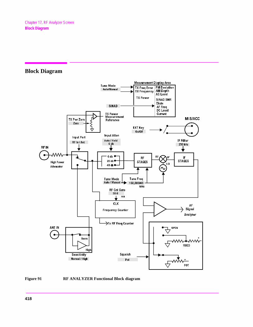
Chapter 17, RF Analyzer ScreenBlock Diagram
Block Diagram
Figure 91 RF ANALYZER Functional Block diagram
48&REQ%RROR
4UNE-ODE
48&REQUENCY
480OWER
&-$EVIATION
!-$EPTH
!#,EVEL
3).!$3.2
$ISTN
!&&REQ
$#,EVEL
#URRENT
!UTO-ANUAL
-EASUREMENT$ISPLAY!REA
3).!$
%84+EY
/N/FF
!UTO(OLD
DB
-)3!##
K(Z
)&&ILTER
!UTO-ANUAL
4UNE&REQ
-(Z
MS
2&
)&
,/
4UNE-ODE
)NPUT0ORT
)NPUT!TTEN
2&
34!'%3
DB
DB
DB
(IGH0OWER
!TTENUATOR
:ERO
2&)N!NT
2&).
480WR:ERO
#,+
&REQUENCY#OUNTER
4O2&&REQ#OUNTER
!.4).
.ORM
(IGH
3ENSITIVITY
.ORMAL(IGH
3QUELCH
0OT
2&#NT'ATE
/0%.
&)8%$
0/4
!&
3IGNAL
!NALYZER
)&
34!'%3
480OWER
-EASUREMENT
2EFERENCE
418
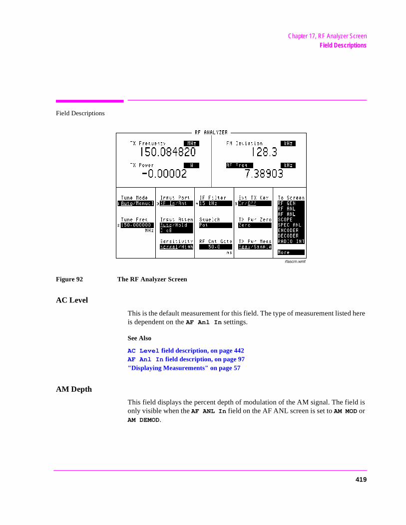
Chapter 17, RF Analyzer ScreenField Descriptions
Field Descriptions
Figure 92 The RF Analyzer Screen
AC Level
This is the default measurement for this field. The type of measurement listed here is dependent on the AF Anl In settings.
See Also
AC Level field description, on page 442AF Anl In field description, on page 97"Displaying Measurements" on page 57
AM Depth
This field displays the percent depth of modulation of the AM signal. The field is only visible when the AF ANL In field on the AF ANL screen is set to AM MOD or AM DEMOD.
rfascrn.wmf
419
Chapter 17, RF Analyzer ScreenField Descriptions
nal the
Ext TX key
This field controls a switch at the MIC/ACC connector. Its intended use is to “key” an external transmitter.
See Also
"MIC/ACC" on page 514
Distn
This field displays the percent of distortion for a 1 kHz signal tone.
FM Deviation
This measurement field displays the frequency deviation between the FM sigand the carrier. The FM Deviation measurement field is only displayed whenAF Anl In field is set to FM Demod or FM Mod.
See Also
AF Anl In field description, on page 97"Displaying Measurements" on page 57
420
Chapter 17, RF Analyzer ScreenField Descriptions
ati-
sired
n yourodedn arise
IF Filter
This field selects the desired IF Filter bandwidth for modulated signals being analyzed.
Input Atten
Input attenuation sets the amount of input attenuation for the RF IN/OUT and ANT IN connectors. This function controls two settings:
• The upper field determines if you want the instrument to set the attenuation automcally (Auto), or if you want to set the value manually (Hold).
• The lower field displays the present attenuation value, and it is used to set the deattenuation level when the upper area is set to Hold.
NOTE: Oscilloscope and Decoder Interference. After a signal is input, the RF autoranging functio(Auto) takes a small amount of time to determine the required input attenuator setting. Iftransmitter begins sending encoded information the instant it transmits, the initial encinformation may not be decoded during the autoranging process. The same situation cawhen trying to display the first part of the demodulated signal on the Oscilloscope.
When decoding a signaling sequence using the decoder, or when trying tocapture the initial modulation waveform of a signal on the Oscilloscope, set theupper field to Hold and set the lower field to an appropriate level for the signalbeing decoded (start with 40 dB).
421
Chapter 17, RF Analyzer ScreenField Descriptions
TX wer
Input Port
This field selects the RF IN/OUT or ANT IN port for making RF measurements. The RF IN/OUT port must be used for making TX Power measurements on this screen.
Operating Considerations
Maximum signal levels at each port are printed on the front panel.
If the RF power at the RF IN/OUT port exceeds allowable limits, a loud warning signal sounds and a message appears at the top of the screen. If this occurs, disconnect the RF power, press [MEAS RESET], and allow the Test Set to cool off for approximately 2 minutes before making any other measurements on this port.
The ANT IN (antenna input) connector provides a highly-sensitive input for very low-level signals (such as “off the air” measurements). You cannot measure (RF) Power on this screen using the antenna port. However, low-level RF poat the antenna port can be measured using the Spectrum Analyzer.
CAUTION: Connecting a signal of >200 mW to the ANT IN port can cause instrument damage (althoughinternal protection circuits can typically withstand a short-duration signal of 1 or 2 Watts).
If the over-power circuit is triggered (signified by a warning message at the topof the screen), remove the signal from the ANT IN port, and press [MEAS RESET] or turn the Test Set off and on to reset it.
422
Chapter 17, RF Analyzer ScreenField Descriptions
hile
RF Cnt Gate
RF counter gate specifies how long the RF counter samples the signal before displaying the frequency. Specifying a shorter gate time may enable you to see frequency fluctuations that might not be seen using a longer gate time.
Sensitivity
RF Analyzer sensitivity adds about 6 dB of sensitivity for the ANT IN port when High is selected.
Operating Considerations
Selecting High sensitivity may cause Spectrum Analyzer1 measurements to be uncalibrated when the ANT IN port is used (a message appears when this occurs).
High-level AM measurements may be distorted when high sensitivity is used with the ANT IN port.
1. Optional on Test Sets
Squelch
This setting determines the squelch operation when demodulating FM, AM or SSB signals. Three settings are available:
• Pot uses the front-panel SQUELCH knob for squelch level adjustment.
• Open disables squelch operation.
• Fixed sets the squelch to a fixed level, disabling the front-panel SQUELCH knobcontrol.
Operating Considerations
Most measurement processes on this screen are not displayed if the incoming signal falls below the squelch level (with the exception of TX Power). The measurements are replaced by four dashes (- - - -) to indicate they have been ‘squelched’.
The decoder and Oscilloscope measurements are also disabled when the signal has been squelched.
Spectrum Analyzer measurements are not affected by the squelch setting (although squelch still affects whether the demodulated signal can be heard wviewing the RF signal).
423
Chapter 17, RF Analyzer ScreenField Descriptions
en1
the
Trying to read a squelched measurement using HP-IB will cause your program to halt until the squelch is either turned down, a measurement is made, or until a program time-out aborts the measurement process.
SINAD
This is the default measurement for this field. Selecting this field displays the following measurement choices:
SINAD
Distortion
SNR (Signal to Noise Ratio)
AF Frequency
DC Level
Current - DC only Operating Considerations
This is a priority control field. Accessing the RX TEST or TX TEST screen overrides any changes made to this field in other screens.
SNR Operation
• Selecting SNR turns off the other audio measurements.
• The RF Generator and AFGen1 must be set up to provide the radio’s carrier. (AFGis automatically turned on and off repeatedly during this measurement.)
• AFGen2 must be turned off.
• The radio’s receiver’s audio output must be connected to the AUDIO IN port (setAF Anl in field to Audio In.
See Also
"Interaction Between Screens" on page 54"Displaying Measurements" on page 57
424
Chapter 17, RF Analyzer ScreenField Descriptions
Tune Freq
RF Analyzer tune frequency sets the center frequency for the RF signal to be analyzed.
See Also
Tune Mode field description (this page)
Tune Mode
This field selects automatic or manual tuning of the RF Analyzer.
Auto causes the RF Analyzer to find the signal with the greatest amplitude>-36 dBm, and set the tune frequency for that signal.
Manual requires the operator to set the tune frequency for the RF signal to be analyzed.
Operating Considerations
Changing the Tune Mode also changes the RF frequency display. Automatic tuning enables the TX Frequency measurement. Manual tuning enables the TX Freq Error measurement.
After autotuning to the desired signal, select Manual to prevent the Tune Freq from changing when the signal is no longer applied.
TX Freq Error/TX Frequency
This measurement area is used to display transmitter frequency error or transmitter frequency.
See Also
Tune Mode field description (this page)
425
Chapter 17, RF Analyzer ScreenField Descriptions
TX Power
Transmitter power measures RF power at the RF IN/OUT port.
Operating Considerations
Maximum signal levels at each port are printed on the front panel.
Only the RF IN/OUT port can be used for measuring TX power on this screen. When the Input Port is set to Ant, four dashes (- - - -) appear in place of digits for this measurement.
Use the Spectrum Analyzer to measure low-level RF power (≤200 mW) at the ANT IN port.
CAUTION: Connecting a signal of >200 mW to the ANT IN port can cause instrument damage (althoughinternal protection circuits can typically withstand a short-duration signal of 1 or 2 Watts).
If the overpower circuit is triggered (signified by a warning message at the top ofthe screen), remove the signal from the ANT IN port, and press[MEAS RESET] or turn the Test Set off and on to reset it.
See Also
Input Port field description, on page 422 (Operating Considerations)TX Power field description (this page)TX Pwr Zero field description, on page 427.
426
Chapter 17, RF Analyzer ScreenField Descriptions
TX Pwr Zero
The transmitter power zero function establishes a 0.0000 W reference for measuring RF power at the RF IN/OUT port.
RF power must not be applied while zeroing. Set the RF GENERATOR screen Ampli-tude field to off to prevent internal cross-coupling into the power detector while zeroing.
Operating Considerations
When power is applied to the RF IN/OUT connector, the temperature of the internal circuitry increases. This can cause changes in the TX Power measurement when low power levels are measured immediately following high power measurements.
When alternately making high and low power measurements, always zero the power meter immediately before making the low power measurements to provide the best measurement accuracy.
427

Chapter 17, RF Analyzer ScreenField Descriptions
428
18
RF Generator Screen
429
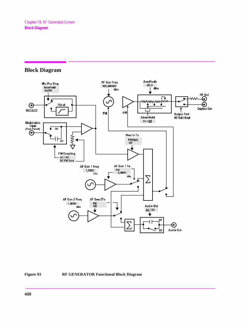
Chapter 18, RF Generator ScreenBlock Diagram
Block Diagram
Figure 93 RF GENERATOR Functional Block Diagram
!TTEN(OLD
!-
&-
2&'EN&REQ
-(Z
D"M
/N/FF
2&/UT$UPL
/UTPUT0ORT
2&/UT
$UPLEX/UT
!#$#
$#&-:ERO
K(Z
K(Z
&-
&-6PK
/FF
!&'EN&REQ
!&'EN4O
!&'EN&REQ !&'EN4O
K(Z
&-
/FF
&-#OUPLING
-)#!##
-ODULATION
)NPUT
2EAR0ANEL
-IC0RE %MP
U3
$#
!#
!UTO(OLD
/N/FF
!MPLITUDE
-OD)N4O
!UDIO/UT
!#$#
!UDIO/UT
!#
$#
430
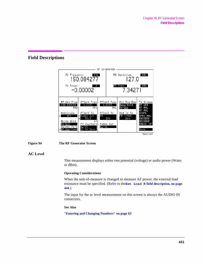
Chapter 18, RF Generator ScreenField Descriptions
Field Descriptions
Figure 94 The RF Generator Screen
AC Level
This measurement displays either rms potential (voltage) or audio power (Watts or dBm).
Operating Considerations
When the unit-of-measure is changed to measure AF power, the external load resistance must be specified. (Refer to theExt Load R field description, on page 444.)
The input for the ac level measurement on this screen is always the AUDIO IN connectors.
See Also
"Entering and Changing Numbers" on page 63
rfgscrn.wmf
431
Chapter 18, RF Generator ScreenField Descriptions
des. op the
ed.
r is
AFGen1 Freq
This Audio Frequency Generator control sets the frequency for the first audio frequency sinewave generator.
AFGen2 Freq
This Audio Frequency Generator control sets the frequency for the second audio frequency sinewave generator. It can also be used to set the Function Generator’s frequency when the signaling encoder is used.
This field is also used to control the send/stop functions for some encoder moFor example, when sending a tone sequence, this field is used to send and stsequence. The field’s name changes to AFGen2 when this type of operation is used.
This field is removed from this screen when NMT encoding or decoding is us(NMT programs can only be run from the NMT Decoder screen.)
See Also
Chapter 10, "Signaling Encoder (AF Generator 2)"
AFGen1 To
This Audio Frequency Generator control is used to set two values:
• The upper field determines whether the AF signal modulates the RF Generator, ooutput through the AUDIO OUT connector.
• The lower field sets the amplitude (including Off). The level at the AUDIO OUT connector is always in volts rms across a low-impedance output.
Operating Considerations
This is a priority control field. Accessing the RX TEST or TX TEST screen overrides any changes made to this field in other screens.
See Also
"Interaction Between Screens" on page 54
432
Chapter 18, RF Generator ScreenField Descriptions
r is
AFGen2 To
This Audio Frequency Generator control is used to set two values:
• The upper field determines whether the AF signal modulates the RF Generator, ooutput through the AUDIO OUT connector.
• The lower field sets the amplitude (including Off). The level at the AUDIO OUT con-nector is always in volts rms for standard sinewave operation across a low-impedanceoutput.
If the signaling option is installed, the sinewave can be set in units of rms or peak. This is done in the Sine Units field for the Function Generator. When non-sinewave waveforms are used, or if the upper field is set to AM or FM, the level is always expressed as a peak value.
See Also
"Function Generator Encoder" on page 339.
Amplitude
RF Generator amplitude adjusts the amplitude of the RF Generator.
Operating Considerations
This is a priority control field. Accessing the RX TEST or TX TEST screen overrides any changes made to this field in other screens.
If a microphone is connected, and the amplitude is off, keying the microphone causes the Amplitude to turn on to its previous level until the microphone is no longer keyed.
See Also
"Interaction Between Screens" on page 54
433
Chapter 18, RF Generator ScreenField Descriptions
n-ator
when
turn
Atten Hold
Attenuator hold prevents the fixed RF output attenuators from switching in and out, eliminating the loss of the output signal as the level is changed. This function is helpful when making squelch measurements.
Operating Considerations
When this function is set to On, the RF output level is restricted to a range above and below the present Amplitude setting. Attempting to set an amplitude outside the allowed range results in an error message and beep (if the beeper is on). RF output level accuracy is greatly degraded outside the allowed range.
Audio Out
Audio output coupling selects ac or dc coupling to the AUDIO OUT connector.
FM Coupling
These fields provide two functions:
• The upper field specifies ac or dc coupling between the MODULATION INPUT conector and the RF Generator’s FM modulator. This field also alters the FM modulto allow DCFM from internal and external modulation sources.
• Selecting the lower field causes the instrument to offset any dc bias that may exist dc coupling is selected.
Mic Pre-Emp
Microphone pre-emphasis determines whether the modulating signal from the MIC/ACC connector goes through or bypasses the 750 ms pre-emphasis network. Two fields are used:
• The upper field is used to specify whether you want the instrument to automaticallypre-emphasis on during FM operation and off for other modulations (Auto), or to leave the pre-emphasis switching to the user’s operation (Hold).
• The lower field tells you whether pre-emphasis is on or off (when Auto operation is selected), or allows you to manually turn pre-emphasis on or off (if Hold is selected).
434
Chapter 18, RF Generator ScreenField Descriptions
set
ent. whenental
erset it.
Mod In To
This modulation input field defines how an external modulation source is used with the RF Generator. Two fields are used:
• The upper field determines whether the rear-panel MODULATION INPUT signal isfor AM or FM modulation of the RF GENERATOR.
• The lower field sets the modulation sensitivity. For instance, if FM (/Vpk) is selected for the upper field, and you set the lower field to 1.0000 kHz, the RF Generator will deviate 1 kHz for every 1 Volt peak at the MODULATION INPUT connector.
In addition, the peak deviation produced by MIC signals will be approximately 1 kHz.
Output Port
Output port selects the desired RF Generator output port.
Operating Considerations
Maximum signal levels at each port are printed on the front panel.
CAUTION: Applying reverse RF power to the DUPLEX OUT connector can damage the instrum(A message is displayed when an overpower conditions occurs.) Whenever possibletesting transceivers, use the RF IN/OUT connector to prevent damage from accidtransmitter keying. If a reverse power condition triggers the internal protection circuit, remove the revpower signal and press the MEAS RESET key, or turn the Test Set off and on to rese
RF Gen Freq
This field sets the RF generator’s frequency.
435
Chapter 18, RF Generator ScreenField Descriptions
en1
the
SINAD
This is the default measurement for this field. Selecting this field displays the following measurement choices:
SINAD
Distortion
SNR (Signal to Noise Ratio)
AF Frequency
DC Level
Current - DC only Operating Considerations
This is a priority control field. Accessing the RX TEST or TX TEST screen overrides any changes made to this field in other screens.
SNR Operation• Selecting SNR turns off the other audio measurement. • The RF Generator and AFGen1 must be set up to provide the radio’s carrier. (AFG
is automatically turned on and off repeatedly during this measurement.) • AFGen2 must be turned off. • The radio’s receiver’s audio output must be connected to the AUDIO IN port (set
AF Anl In field to Audio In).
See Also
"Interaction Between Screens" on page 54"Displaying Measurements" on page 57
436
Chapter 18, RF Generator ScreenField Descriptions
TX Freq ErrorTX Frequency
This measurement displays transmitter frequency error or absolute transmitter frequency.
See Also
Tune Mode field description, on page 297"Displaying Measurements" on page 57
TX Power
Transmitter power measures RF power at the RF IN/OUT port.
Operating Considerations
Maximum signal levels at each port are printed on the front panel.
Only the RF IN/OUT port can be used for measuring TX power on this screen. When the Input Port 1is set to Ant, four dashes (- - - -) appear in place of digits for this measurement.
Use the Spectrum Analyzer to measure low-level RF power (≤200 mW) at the ANT IN port.
1. The Input Port field is accessed on the TX TEST, DUPLEX TEST, and RF ANALYZER screens.
CAUTION: Connecting a signal of >200 mW to the ANT IN port can cause instrument damage (althoughinternal protection circuits can typically withstand a short-duration signal of 1 or 2 Watts).
If the overpower circuit is triggered (signified by a warning message at the top ofthe screen), remove the signal from the ANT IN port, and press the MEAS RESET key or turn the Test Set off and on reset it.
See Also
TX Power field description, on page 426TX Pwr Zero field description, on page 427
437

Chapter 18, RF Generator ScreenField Descriptions
438
19
RX Test Screen
439
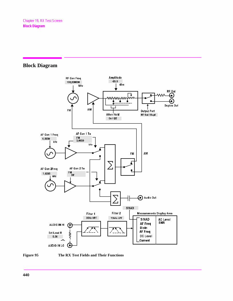
Chapter 19, RX Test ScreenBlock Diagram
Block Diagram
Figure 95 The RX Test Fields and Their Functions
!TTEN(OLD
!-
&-
2&'EN&REQ
-(Z
D"M
/N/FF
2&/UT$UPL
/UTPUT0ORT
2&/UT
$UPLEX/UT
!MPLITUDE
!&'EN&REQ
!&'EN4O
!&'EN&REQ
!&'EN4O
&-
!-
K(Z
K(Z
&-
/FF
&-
(Z(0&
K(Z,0&
&ILTER
&ILTER
!UDIO/UT
!5$)/).()
%XT,OAD2
!5$)/).,/
3).!$
-EASUREMENTS$ISPLAY!REA
K(Z
3).!$
!&&REQ
$ISTN
!&&REQ
$#,EVEL
#URRENT
!#,EVEL
3.2
440
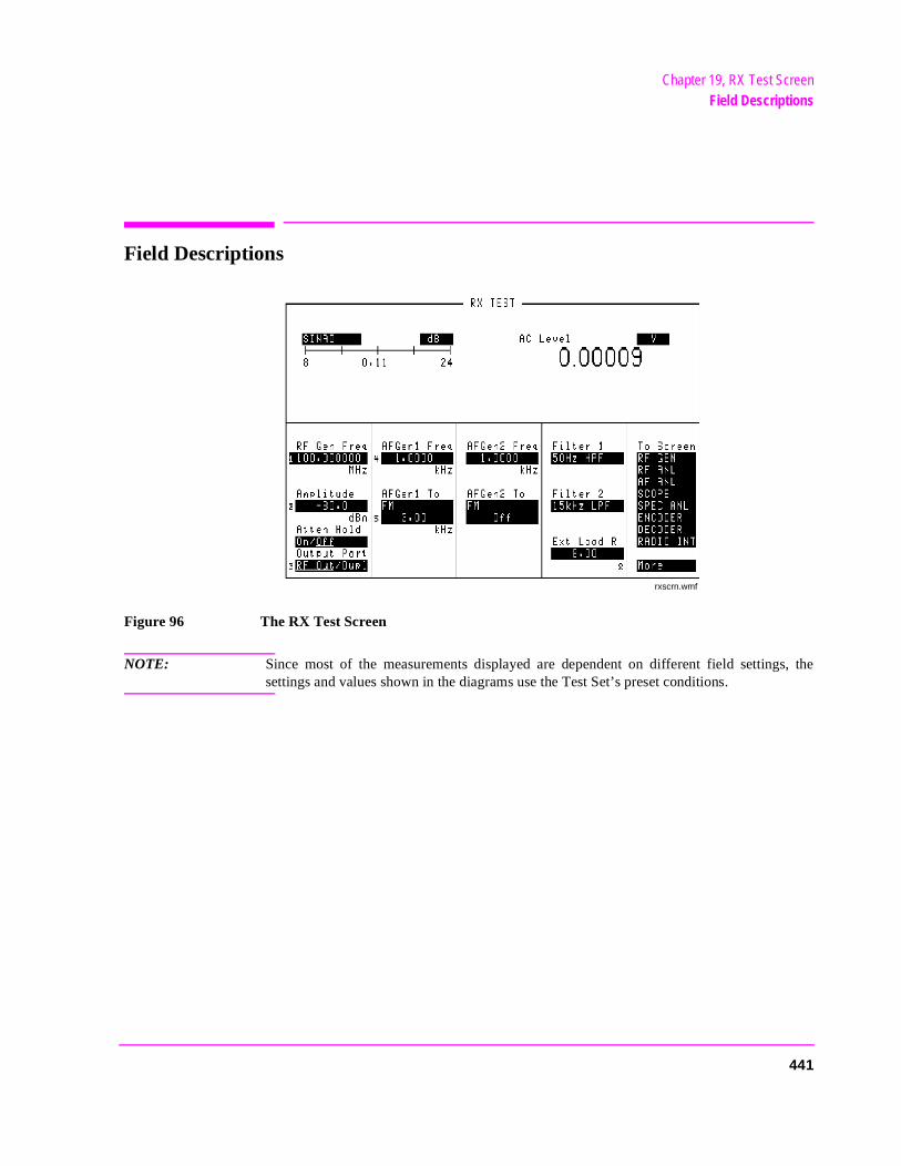
Chapter 19, RX Test ScreenField Descriptions
Field Descriptions
Figure 96 The RX Test Screen
NOTE: Since most of the measurements displayed are dependent on different field settings, thesettings and values shown in the diagrams use the Test Set’s preset conditions.
rxscrn.wmf
441
Chapter 19, RX Test ScreenField Descriptions
des. op the .
ed.
AC Level
This measurement displays either rms potential (voltage) or audio power (Watts or dBm).
Operating Considerations
When the unit-of-measure is changed to measure AF power, the external load resistance must be specified. (Refer to theExt Load R field description, on page 444.)
The input for the ac level measurement on this screen is always the AUDIO IN connectors.
See Also
"Entering and Changing Numbers" on page 63
AFGen1 Freq
This Audio Frequency Generator control sets the frequency for the first audio frequency sinewave generator.
AFGen2 Freq
This Audio Frequency Generator control sets the frequency for the second audio frequency sinewave generator. It can also be used to set the Function Generator’s frequency when the signaling encoder is used.
This field is also used to control the send/stop functions for some encoder moFor example, when sending a tone sequence, this field is used to send and stsequence. The field name changes to AFGen2 when this type of operation is used
This field is removed from this screen when NMT encoding or decoding is us(NMT programs can only be run from the NMT Decoder screen.)
See Also
Chapter 10, "Signaling Encoder (AF Generator 2)".
442
Chapter 19, RX Test ScreenField Descriptions
s out-
load
r is
AFGen1 To
This Audio Frequency Generator control is used to set two values:
• The upper field determines whether the AF signal modulates the RF Generator or iput through the AUDIO OUT connector.
• The lower field sets the amplitude (including Off). The AUDIO OUT level is set either in volts rms (across a low-impedance output) or dBm, mW, or W across a 600-ohm(mW is selected by pressing [SHIFT], [ENTER]).
Operating Considerations
The upper field is a priority control field. Accessing the RX TEST or TX TEST screen overrides any changes made to this field in other screens.
See Also
"Interaction Between Screens" on page 54
AFGen2 To
This Audio Frequency Generator control is used to set two values:
• The upper field determines whether the AF signal modulates the RF Generator, ooutput through the AUDIO OUT connector.
• The lower field sets the amplitude (including Off). The AUDIO OUT level is always in volts rms for standard sinewave operation across a low-impedance output.
If the signaling option is installed, the sinewave can be set in units of rms or peak. This is done in the Sine Units field for the Function Generator. When non-sinewave waveforms are used, or if the upper field is set to AM or FM, the level is always expressed as a peak value.
See Also
"Function Generator Encoder" on page 339
443
Chapter 19, RX Test ScreenField Descriptions
Amplitude
The amplitude field adjusts the amplitude of the RF Generator.
Operating Considerations
This is a priority control field. Accessing the RX TEST or TX TEST screen overrides any changes made to this field in other screens.
If a microphone is connected, and the amplitude is off, keying the microphone causes the amplitude to turn on to its previous level until the microphone is no longer keyed.
See Also
Atten Hold field description, on page 444"Interaction Between Screens" on page 54"MIC/ACC" on page 514
Atten Hold
Attenuator hold prevents the fixed RF output attenuators from switching in and out, eliminating the brief loss of the output signal as the level is changed. This function is helpful when making squelch measurements.
Operating Considerations
When this function is set to On, the RF output level is restricted to a range of 15 dB around the present Amplitude setting. Attempting to set an amplitude outside the allowed range results in an error message and beep (if the beeper is on). RF output level accuracy is uncalibrated outside the allowed range.
Ext Load R
External load resistance is used to calculate and display AF power dissipated in an external load resistance. Power is calculated using the voltage measured at the AUDIO IN connections and the resistance value you enter into this field.
See Also
AC Level field description, on page 442
444
Chapter 19, RX Test ScreenField Descriptions
Filter 1 and Filter 2
Filters 1 and 2 select a variety of standard and optional filters. Selecting either field lists the choices available for that field.
See Also
Chapter 5, "AF Analyzer Screen"
Output Port
Output port selects the desired RF Generator output port.
Operating Considerations
Maximum signal levels at each port are printed on the front panel.
CAUTION: Applying reverse RF power to the DUPLEX OUT connector can damage the instrument. (Amessage is displayed when an over-power conditions occurs.) Whenever possible whentesting transceivers, use the RF IN/OUT connector to prevent damage from accidentaltransmitter keying.
CAUTION: If a reverse power condition triggers the internal protection circuit, remove the reverse powersignal and press the MEAS RESET key or turn the Test Set off and on to reset it.
RF Gen Freq
RF Generator frequency sets the generator’s frequency.
445
Chapter 19, RX Test ScreenField Descriptions
en1
the
SINAD
This measurement field is used to select and display any one of the following measurements:
SINAD
Distortion
SNR (Signal to Noise Ratio)
AF Frequency
DC Level
Current - DC only Operating Considerations
This is a priority control field. Accessing the RX TEST or TX TEST screen overrides any changes made to this field in other screens.
SNR Operation
• Selecting SNR turns off the other audio measurement.
• The RF Generator and AFGen1 must be set up to provide the radio’s carrier. (AFGis automatically turned on and off repeatedly during this measurement.)
• AFGen2 must be turned off.
• The radio’s receiver’s audio output must be connected to the AUDIO IN port (setAF Anl In field to Audio In).
See Also
"Interaction Between Screens" on page 54"Displaying Measurements" on page 57
446
20
Service Screen
NOTE: This screen is used for component-level troubleshooting by the manufacturer. This method oftroubleshooting is not currently supported outside of the factory.
This screen allows you to monitor individual circuit node measurements and change various MUX and DAC latch settings for isolating faulty modules. To access the SERVICE screen, you must first access the CONFIGURE screen, then select Service from the To Screen menu in the bottom-right corner.
447
Chapter 20, Service ScreenField Descriptions
e onger
s.
Field Descriptions
Counter Connection
This field selects the desired circuit node to connect to the frequency counter.
Frequency
This measurement field displays the frequency measurement for the circuit node shown in the Counter Connection field.
Gate Time
This field is used to adjust the frequency counter’s gate time. A shorter gate timmay enable you to see frequency fluctuations that might not be seen using a lgate time.
Latch
This field is used to alter the circuit latches that control a variety of operationThe value of the selected latch is displayed and changed in the Value field.
448
Chapter 20, Service ScreenField Descriptions
RAM Initialize
Selecting this field clears all SAVE registers and test programs that may be in RAM and resets all latches to their factory power-up configuration.
Operating Considerations
If you have saved one or more instrument setups using the SAVE function, using this function will permanently remove them.
Value
This field displays and changes the value for the latch shown in the Latch field.
Voltage
This measurement field displays the voltage measurement for the circuit node shown in the Voltmeter Connection field.
Voltmeter Connection
This field selects the desired circuit node for voltage measurements. The reading is displayed in the Voltage measurement field.
449

Chapter 20, Service ScreenField Descriptions
450
21
the
Spectrum Analyzer Screen
The SPECTRUM ANALYZER screen’s controls are arranged in four menus. Themenus are accessed using the Controls field. The field descriptions are grouped by menu names. Assigning global USER keys to the most-used functions onmenus allows you to access the functions without having to change menus.
451
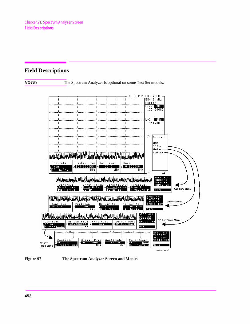
Chapter 21, Spectrum Analyzer ScreenField Descriptions
Field Descriptions
NOTE: The Spectrum Analyzer is optional on some Test Set models.
Figure 97 The Spectrum Analyzer Screen and Menus
sascrn.wmf
452
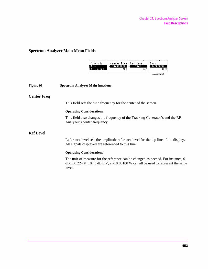
Chapter 21, Spectrum Analyzer ScreenField Descriptions
ce, 0 same
Spectrum Analyzer Main Menu Fields
Figure 98 Spectrum Analyzer Main functions
Center Freq
This field sets the tune frequency for the center of the screen.
Operating Considerations
This field also changes the frequency of the Tracking Generator’s and the RFAnalyzer’s center frequency.
Ref Level
Reference level sets the amplitude reference level for the top line of the display.All signals displayed are referenced to this line.
Operating Considerations
The unit-of-measure for the reference can be changed as needed. For instandBm, 0.224 V, 107.0 dB mV, and 0.00100 W can all be used to represent the level.
sascrn2.wmf
453
Chapter 21, Spectrum Analyzer ScreenField Descriptions
d,
RF In/Ant
This field selects the input port for the analyzer.
Operating Considerations
Maximum signal levels at each port are printed on the front panel.
CAUTION: Connecting a signal of >200 mW to the ANT IN port can cause instrument damage (althoughinternal protection circuits can typically withstand a short-duration signal of 1 or 2 Watts).
If the overpower circuit is triggered (signified by a warning message at the top ofthe screen), remove the signal from the ANT IN port, and press the MEAS RESET key or turn the Test Set off and on to reset it.
Using the ANT IN port with the field set to High can result in uncalibrated operation (a message appears on the screen when this happens). The purpose for the high sensitivity setting is to allow you to look and listen to very low level signals when absolute accuracy is not essential.
See Also
Sensitivity field description, on page 463
Span
Sets the span of frequencies to be displayed on the screen.
Operating Considerations
When the Tracking Generator is used, the span also defines the frequency sweep range.
Spans >1.5 MHz disable the AF Analyzer when the analyzer’s AF Anl In field is set to FM Demod, AM Demod, or SSB Demod. This disables all the AF Analyzer’s measurement and output functions. When the AF Analyzer’s AF Anl
In field is set to any of the other available inputs, such as Audio In or Ext Mothe speaker and AUDIO MONITOR OUTPUT are not affected when the Spectrum Analyzer’s span is changed.
454
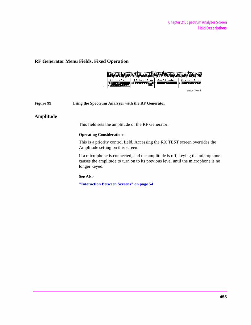
Chapter 21, Spectrum Analyzer ScreenField Descriptions
RF Generator Menu Fields, Fixed Operation
Figure 99 Using the Spectrum Analyzer with the RF Generator
Amplitude
This field sets the amplitude of the RF Generator.
Operating Considerations
This is a priority control field. Accessing the RX TEST screen overrides the Amplitude setting on this screen.
If a microphone is connected, and the amplitude is off, keying the microphone causes the amplitude to turn on to its previous level until the microphone is no longer keyed.
See Also
"Interaction Between Screens" on page 54
sascrn3.wmf
455
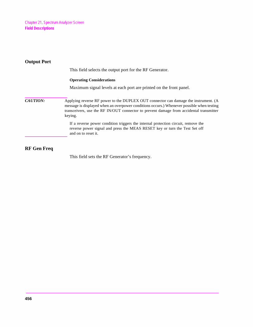
Chapter 21, Spectrum Analyzer ScreenField Descriptions
Output Port
This field selects the output port for the RF Generator.
Operating Considerations
Maximum signal levels at each port are printed on the front panel.
CAUTION: Applying reverse RF power to the DUPLEX OUT connector can damage the instrument. (Amessage is displayed when an overpower conditions occurs.) Whenever possible when testingtransceivers, use the RF IN/OUT connector to prevent damage from accidental transmitterkeying.
If a reverse power condition triggers the internal protection circuit, remove thereverse power signal and press the MEAS RESET key or turn the Test Set offand on to reset it.
RF Gen Freq
This field sets the RF Generator’s frequency.
456
Chapter 21, Spectrum Analyzer ScreenField Descriptions
e o
RF Generator Menu Fields, Tracking Operation
Figure 100 Using the Spectrum Analyzer with the Tracking Generator
The Tracking Generator performs a frequency sweep operation. The start and stop frequencies are determined by the Main Menu Span setting. This allows you to characterize devices (such as filter networks) over a wide span of frequencies.
An RF offset can be set between the Tracking Generator and the center frequency of the Spectrum Analyzer. This allows you to look at a signal that is related to a source whose frequency is outside of the displayed span.
Amplitude
This field sets the amplitude of the Tracking Generator.
Operating Considerations
This field operates independently of the RF Generator’s amplitude settings inother screens.
If a microphone is connected, and the amplitude is off, keying the microphoncauses the amplitude to turn on to its previous level until the microphone is nlonger keyed.
sascrn4.wmf
457
Chapter 21, Spectrum Analyzer ScreenField Descriptions
fre-
ined
Offset Freq
Frequency offset (RF Generator) sets the difference between the instantaneous frequencies of the Tracking Generator and the center frequency of the Spectrum Analyzer.
Operating Considerations
The offset can be a positive or negative value. When set to zero, the Tracking Generator produces a sweeping signal that matches the Spectrum Analyzer’s tune frequency.
Port/Sweep
This control performs two functions:
• The upper field specifies the output port of the Tracking Generator.
• The lower field specifies whether the Tracking Generator sweeps from low-to-highquencies (Norm), or from high-to-low frequencies (Invert). (The Spectrum Analyzer always sweeps from low to high frequencies.) The swept frequency range is determby the Span setting in the Spectrum Analyzer’s Main Menu.
Operating Considerations
When using the Tracking Generator, if the output port is set RF Out, or the main menu Input Port is set to RF In, internal instrument coupling can occur. For the best isolation between the Tracking Generator and the Spectrum Analyzer, use Dupl for the output, and Ant for the input.
For measurements on high-power devices, such as amplifiers, use the RF IN/OUT port for the input.
458
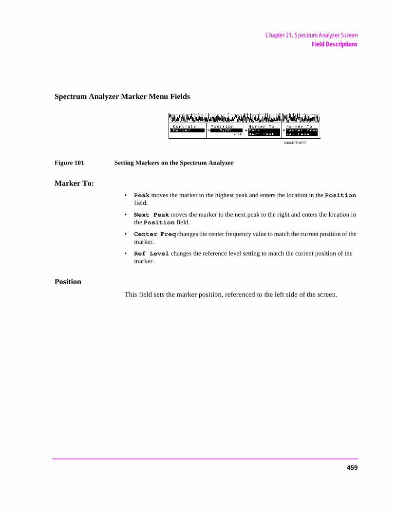
Chapter 21, Spectrum Analyzer ScreenField Descriptions
n in
f the
the
Spectrum Analyzer Marker Menu Fields
Figure 101 Setting Markers on the Spectrum Analyzer
Marker To:
• Peak moves the marker to the highest peak and enters the location in the Position field.
• Next Peak moves the marker to the next peak to the right and enters the locatiothe Position field.
• Center Freq changes the center frequency value to match the current position omarker.
• Ref Level changes the reference level setting to match the current position of marker.
Position
This field sets the marker position, referenced to the left side of the screen.
sascrn5.wmf
459
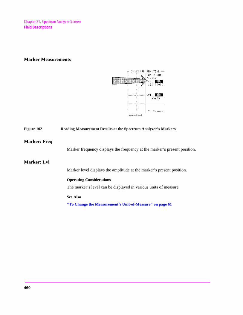
Chapter 21, Spectrum Analyzer ScreenField Descriptions
Marker Measurements
Figure 102 Reading Measurement Results at the Spectrum Analyzer’s Markers
Marker: Freq
Marker frequency displays the frequency at the marker’s present position.
Marker: Lvl
Marker level displays the amplitude at the marker’s present position.
Operating Considerations
The marker’s level can be displayed in various units of measure.
See Also
"To Change the Measurement’s Unit-of-Measure" on page 61
sascrn1.wmf
460
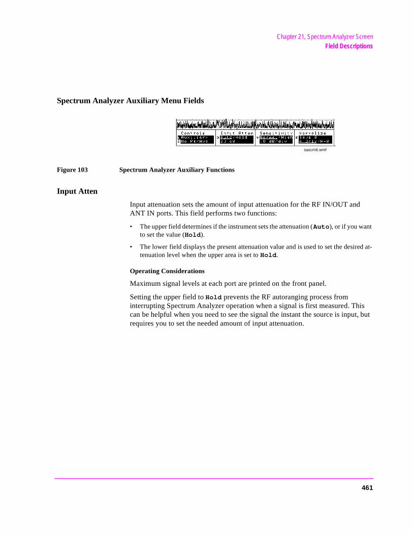
Chapter 21, Spectrum Analyzer ScreenField Descriptions
ed at-
Spectrum Analyzer Auxiliary Menu Fields
Figure 103 Spectrum Analyzer Auxiliary Functions
Input Atten
Input attenuation sets the amount of input attenuation for the RF IN/OUT and ANT IN ports. This field performs two functions:
• The upper field determines if the instrument sets the attenuation (Auto), or if you want to set the value (Hold).
• The lower field displays the present attenuation value and is used to set the desirtenuation level when the upper area is set to Hold.
Operating Considerations
Maximum signal levels at each port are printed on the front panel.
Setting the upper field to Hold prevents the RF autoranging process from interrupting Spectrum Analyzer operation when a signal is first measured. This can be helpful when you need to see the signal the instant the source is input, but requires you to set the needed amount of input attenuation.
sascrn6.wmf
461

Chapter 21, Spectrum Analyzer ScreenField Descriptions
).
s
Normalize
This area performs three display operations:
• Save B saves the currently-displayed trace for the A-B operation.
• A only provides a continuously-updated display (the “normal” mode of operation
• A-B displays the difference between the trace saved using Save B and the currently displayed trace. The comparison can yield either losses or gains in amplitude.
Operating Considerations
The A-B function works correctly only if the center frequency and span settings are the same for both signals.
The reference level (Ref Level) can be changed to move the trace below the top line of the display if the A-B function results in a gain.
The the HOLD key can be used to “freeze” the display at any time. This allowyou to view a trace before performing the Save B or A-B functions.
462
Chapter 21, Spectrum Analyzer ScreenField Descriptions
until of
ls. mes--
No Pk/Avg
This field performs two functions:
Pk Hold (peak hold) prevents the Spectrum Analyzer from erasing the previous trace each time it sweeps. This causes the traces to ‘build-up’ on the screen Off, No Pk/Avg or the MEAS RESET key is selected. This allows the capturetransient signals that are not displayed long enough to view during normal operation.
Avg 1 through (video averaging) enables the Spectrum Analyzer to display a trace representing the average of several measurements. The number of samples used for measurement averaging range from 1 to 100 (see below). No Pk/Avg and Off function identically. Off is provided to maintain backwards compatibility with earlier firmware and software.
• No Pk/Avg means that peak hold and video averaging are off.• Pk Hold means that peak hold is on. • Avg [n] enables video averaging over [n] measurements,
where n = 1, 2, 3, 4, 5, 10, 20, 50, or 100 • Off means that peak hold and video averaging are off.
Operating Considerations
After capturing the desired signal, you can use the HOLD function (press and release the SHIFT key, then the PREV key) to prevent additional signals from building-up on the display.
Sensitivity
This area performs two functions:
• The upper field selects Normal or High sensitivity for the RF input. The High setting adds about 6 dB of sensitivity to the ANT IN port for looking at very low level signaHowever, this setting can cause measurements to be uncalibrated (indicated by asage on the screen). High sensitivity can also cause high-level AM signals to be distorted.
• The lower field selects the vertical resolution of the display. You can choose from1 dB, 2 dB, or 10 dB per graticule.
463
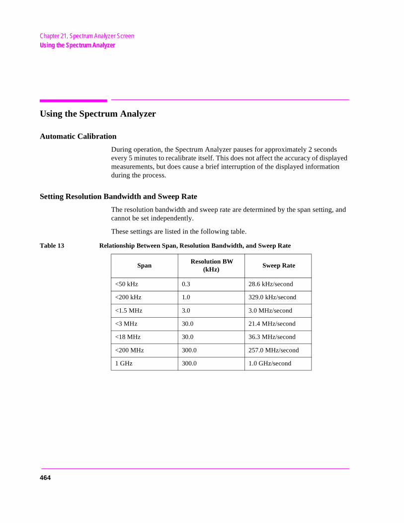
Chapter 21, Spectrum Analyzer ScreenUsing the Spectrum Analyzer
Using the Spectrum Analyzer
Automatic Calibration
During operation, the Spectrum Analyzer pauses for approximately 2 seconds every 5 minutes to recalibrate itself. This does not affect the accuracy of displayed measurements, but does cause a brief interruption of the displayed information during the process.
Setting Resolution Bandwidth and Sweep Rate
The resolution bandwidth and sweep rate are determined by the span setting, and cannot be set independently.
These settings are listed in the following table.
Table 13 Relationship Between Span, Resolution Bandwidth, and Sweep Rate
Span Resolution BW
(kHz) Sweep Rate
<50 kHz 0.3 28.6 kHz/second
<200 kHz 1.0 329.0 kHz/second
<1.5 MHz 3.0 3.0 MHz/second
<3 MHz 30.0 21.4 MHz/second
<18 MHz 30.0 36.3 MHz/second
<200 MHz 300.0 257.0 MHz/second
1 GHz 300.0 1.0 GHz/second
464

22
Tests Screen
465
Chapter 22, Tests ScreenDescription of the Tests Subsystem
r
g
Description of the Tests Subsystem
The TESTS screens are the also referred to as the Tests Subsystem; a group of screens used to create, edit, and run automated test programs. Using program control, the Test Set can run radio tests by itself and control other instruments using the HP-IB or Serial Port. The HP 11807B Cell Site is an example this type of testing.
Tests can be run from memory cards, the Test Set’s internal ROM or RAM, ofrom an external disk drive.
Test programs are written in the HP Instrument BASIC (IBASIC) programminlanguage.
For detailed (step-by-step) instructions about using the TESTS screens, see your Radio Test Software’s documentation or the Test Set’s Programmer’s Guide.
466
Chapter 22, Tests ScreenDescription of the Tests Subsystem
ard.
or-
for
int. e.
re ontin-d.
n-re test
ults page creen.
tand-
Tests Subsystem Screens
When you press the TESTS key, you access the main TESTS screen. The other screens of the subsystem are accessed using the CUSTOMIZE TEST PROCEDURE: or SET UP TEST SET: lists at the bottom of this screen.
TESTS Subsystem Screens
• Main Menu is used to load a test procedure from a disk, RAM, ROM, or memory cIt is also used to access the other screens in the Tests Subsystem.
• Channel Information is used to specify transmitter and receiver frequency infmation for the radio being tested and to enter squelch and signaling information.
• Test Parameters is used to tell the Test Set the requirements of the test systemtesting your radio.
• Order of Tests is used to define a test sequence from a list of possible tests.
• Pass/Fail Limits is used to specify the upper and lower limits for each test poIf a limit is violated during a test, an F appears next to the test value to indicate a failur
• Save/Delete Procedure is used to save and delete test procedures.
• Execution Conditions is used to control which test results are output and whethe results are printed (CRT/printer). This screen also controls whether tests run cuously or singly, and whether the test continues or stops after a failure is detecte
• External Devices is used to specify what types of external equipment are conected to the Test Set and their addresses. It is also used to specify where to storesult data.
• Printer Setup is used to control which test results are output and where the resare printed. This screen is also used for basic formatting of the printout (lines per and form feeds). Printer port and printer model number are also chosen on this s
• IBASIC Cntrl is used to run IBASIC programs. This screen is also used as a salone IBASIC computer. See the Instrument BASIC Programmer’s Handbook for in-formation about writing your own tests for the Test Set.
467
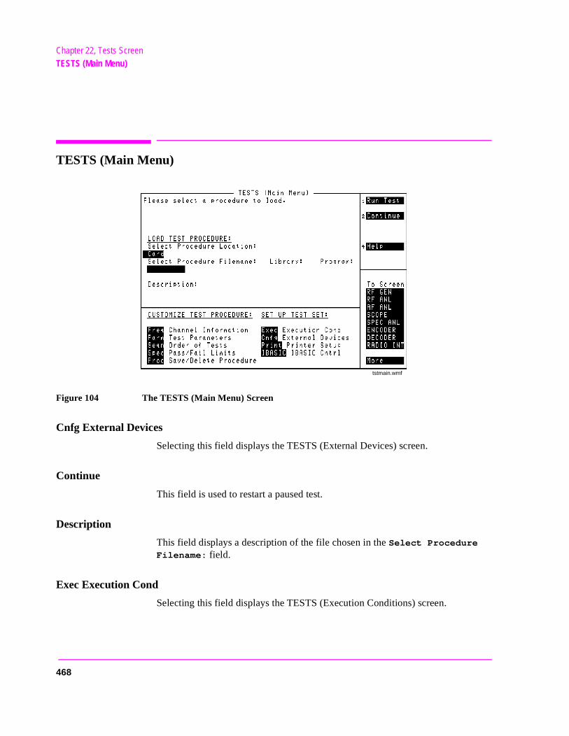
Chapter 22, Tests ScreenTESTS (Main Menu)
TESTS (Main Menu)
Figure 104 The TESTS (Main Menu) Screen
Cnfg External Devices
Selecting this field displays the TESTS (External Devices) screen.
Continue
This field is used to restart a paused test.
Description
This field displays a description of the file chosen in the Select Procedure Filename: field.
Exec Execution Cond
Selecting this field displays the TESTS (Execution Conditions) screen.
tstmain.wmf
468

Chapter 22, Tests ScreenTESTS (Main Menu)
Freq Channel Information
Selecting this field displays the TESTS (Channel Information) screen.
IBASIC IBASIC Cntrl
Selecting this field displays the TESTS (IBASIC Controller) screen.
Library
This field displays the library information of the file chosen in the Select Procedure Filename: field.
Parm Test Parameters
Selecting this field displays the TESTS (Test Parameters) screen.
Print Printer Setup
Selecting this field displays the TESTS (Printer Setup) screen.
469
Chapter 22, Tests ScreenTESTS (Main Menu)
Proc Save/Delete Procedure
Selecting this field displays the TESTS (Save/Delete Procedure) screen.
Program
This field displays program information for the file chosen in the Select Procedure Filename: field.
Run Test
Selecting this field loads and runs the test chosen in the Select Procedure Filename: field.
Select Procedure Filename
This field is used to select the file you want to load from the location chosen in the Select Procedure Location: field.
Select Procedure Location
This field is used the select the location of the procedure to load. Procedures can be loaded from disk, card, ROM, or RAM.
Seqn Order of Tests
Selecting this field displays the TESTS (Order of Tests) screen.
Spec Pass/Fail Limits
Selecting this field displays the TESTS (Pass/Fail Limits) screen.
470
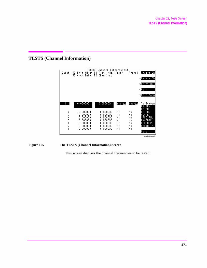
Chapter 22, Tests ScreenTESTS (Channel Information)
TESTS (Channel Information)
Figure 105 The TESTS (Channel Information) Screen
This screen displays the channel frequencies to be tested.
tstcinfo.wmf
471
Chapter 22, Tests ScreenTESTS (Channel Information)
t
Delete Ch
This field allows you to delete a channel from the frequency table at the bottom of the screen.
Insert Ch
This field allows you to enter a new channel in frequency table at the bottom of the screen.
Operating Considerations
You are required to specify if the test channel is a prime test channel. Prime test channels are the radio channels primarily used by the radio operator; they are the channels you are the most concerned about testing.
Use the RX Chan Info or TX Chan Info fields if the channel requires a tone code or frequency for testing radios that have CTCSS (Continuous Tone-Controlled Squelch System) squelch.
For example, if your radio uses a CTCSS tone of 91.5 Hz, you could enter the tone frequency in both RX and TX channel information fields as CT FR91.5 or you could enter the tone code itself as CT ZZ. The specific entries are described in your HP 11807B software manual.
When testing cellular radios, the Channel Information is the channel number you are testing (don’t confuse this with the Chan# field used to list channels on this screen). When the cellular radio channel number is entered, the HP 11807B software automatically sets the channel frequencies when testing. You do noneed to enter the RX and TX frequencies because they correspond directly to the channel numbers.
NOTE: Enter −1 in the RX and TX test frequency fields to have all subsequent channels ignored whentesting is started.
Main Menu
Selecting this field returns you to the TESTS (Main Menu) screen.
Print All
This field allows you to print the Test Set’s screen image.
472
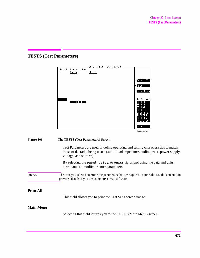
Chapter 22, Tests ScreenTESTS (Test Parameters)
TESTS (Test Parameters)
Figure 106 The TESTS (Test Parameters) Screen
Test Parameters are used to define operating and testing characteristics to match those of the radio being tested (audio-load impedance, audio power, power-supply voltage, and so forth).
By selecting the Parm#, Value, or Units fields and using the data and units keys, you can modify or enter parameters.
NOTE: The tests you select determine the parameters that are required. Your radio test documentationprovides details if you are using HP 11807 software.
Print All
This field allows you to print the Test Set’s screen image.
Main Menu
Selecting this field returns you to the TESTS (Main Menu) screen.
tstparam.wmf
473
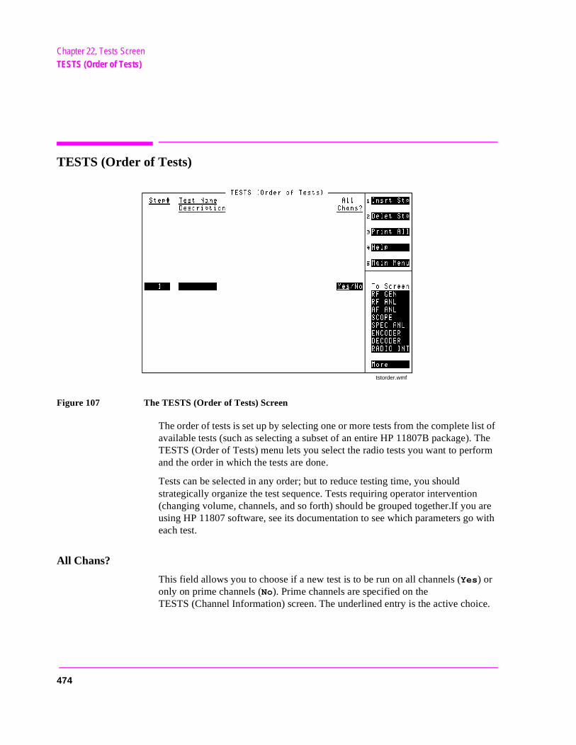
Chapter 22, Tests ScreenTESTS (Order of Tests)
TESTS (Order of Tests)
Figure 107 The TESTS (Order of Tests) Screen
The order of tests is set up by selecting one or more tests from the complete list of available tests (such as selecting a subset of an entire HP 11807B package). The TESTS (Order of Tests) menu lets you select the radio tests you want to perform and the order in which the tests are done.
Tests can be selected in any order; but to reduce testing time, you should strategically organize the test sequence. Tests requiring operator intervention (changing volume, channels, and so forth) should be grouped together.If you are using HP 11807 software, see its documentation to see which parameters go with each test.
All Chans?
This field allows you to choose if a new test is to be run on all channels (Yes) or only on prime channels (No). Prime channels are specified on the TESTS (Channel Information) screen. The underlined entry is the active choice.
tstorder.wmf
474
Chapter 22, Tests ScreenTESTS (Order of Tests)
t to
e or
Delet Stp
This field allows you to delete a step from the test list at the bottom of the screen.
Insrt Stp
This field allows you to enter a step in the test list at the bottom of the screen.
Operating Considerations
When inserting a new test, you must select the Step# where you want to insert a new test. When inserted, the new test forces the current test (at that step #) down one step, and a duplicate of the current test is inserted. This duplicate is overwritten when the new test is selected.
See Also
Programmer’s Guide
Main Menu
Selecting this field returns you to the TESTS (Main Menu) screen.
Print All
This field allows you to print the Test Set’s screen image.
Step#
The Step# field lists the order of selected tests for the current procedure.
Operating Considerations
Use the knob, up-arrow, or down-arrow key to select the step where you wandelete, replace, or insert a test.
Test Name
This field displays the names of the tests available from the software packagprogram currently selected. As you turn the knob, the Test Name for the corresponding step appears above the test’s Description.
475
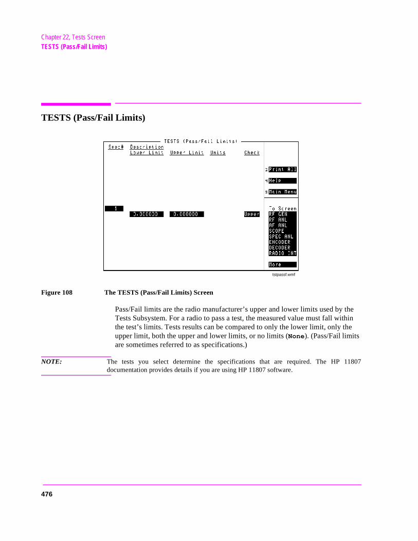
Chapter 22, Tests ScreenTESTS (Pass/Fail Limits)
he thin e
TESTS (Pass/Fail Limits)
Figure 108 The TESTS (Pass/Fail Limits) Screen
Pass/Fail limits are the radio manufacturer’s upper and lower limits used by tTests Subsystem. For a radio to pass a test, the measured value must fall withe test’s limits. Tests results can be compared to only the lower limit, only thupper limit, both the upper and lower limits, or no limits (None). (Pass/Fail limits are sometimes referred to as specifications.)
NOTE: The tests you select determine the specifications that are required. The HP 11807documentation provides details if you are using HP 11807 software.
tstpassf.wmf
476
Chapter 22, Tests ScreenTESTS (Pass/Fail Limits)
ults.
Check
This field is used to select whether the test will verify only upper, only lower, both, or none of the specified limits.
Operating Considerations
Selecting both upper and lower limits increases test time, but may be required for some tests.
Lower Limit
This field is used to set the lower limit to be compared with the measured results. If the measured result is below this limit, the test will fail.
Main Menu
Selecting this field returns you to the TESTS (Main Menu) screen.
Print All
This field allows you to print the Test Set’s screen image.
Spec#
The Spec# field lists the order of selected pass/fail limits for the current procedure.
Units
The Units column indicates the unit-of-measure used for the limits (%, dBm,kHz, and so forth).
Upper Limit
This field is used to set the upper limit to be compared with the measured resIf the measured result is above this limit, the test will fail.
477
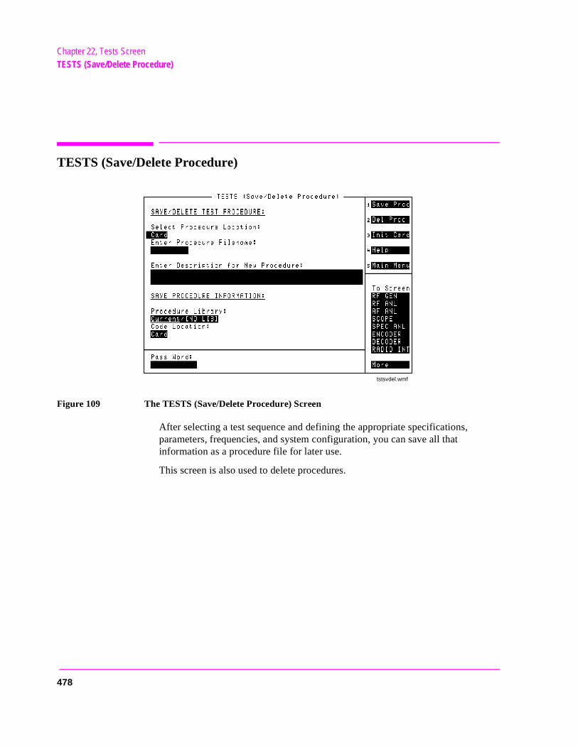
Chapter 22, Tests ScreenTESTS (Save/Delete Procedure)
TESTS (Save/Delete Procedure)
Figure 109 The TESTS (Save/Delete Procedure) Screen
After selecting a test sequence and defining the appropriate specifications, parameters, frequencies, and system configuration, you can save all that information as a procedure file for later use.
This screen is also used to delete procedures.
tstsvdel.wmf
478
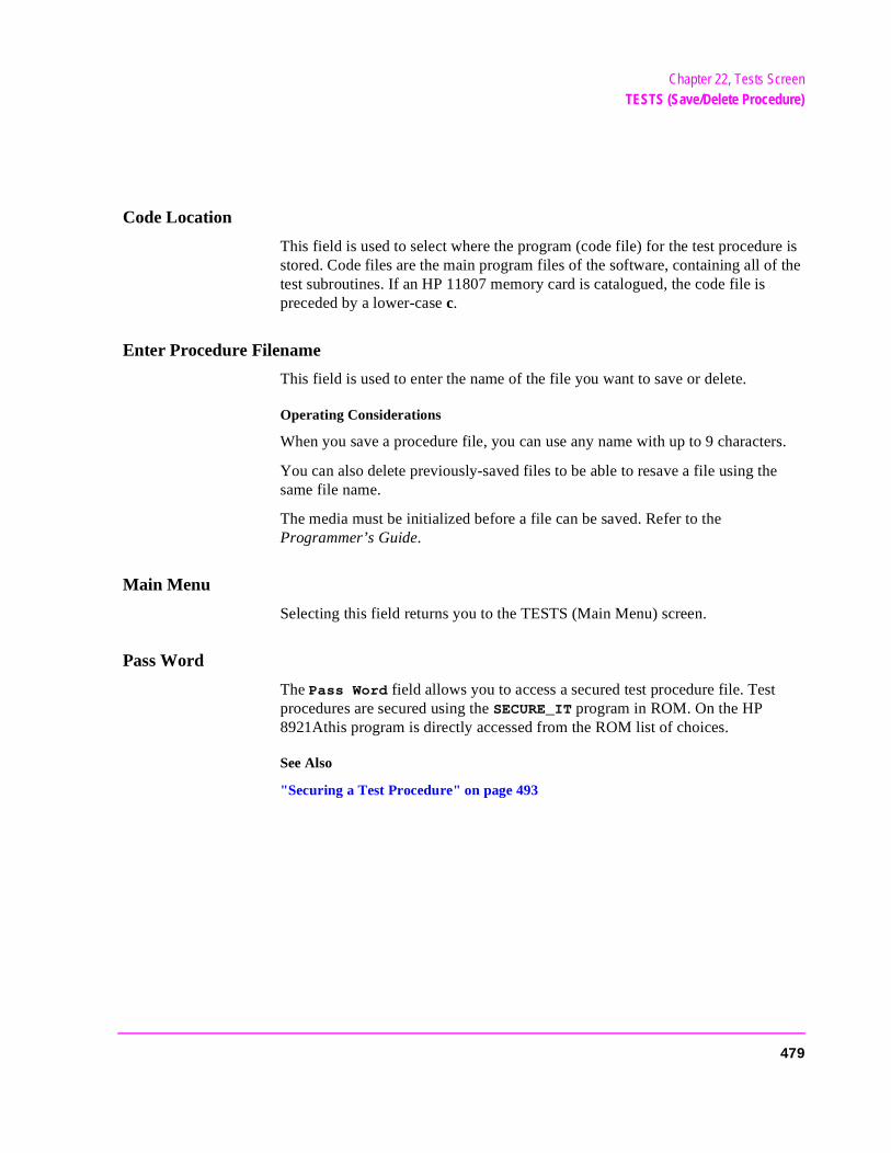
Chapter 22, Tests ScreenTESTS (Save/Delete Procedure)
Code Location
This field is used to select where the program (code file) for the test procedure is stored. Code files are the main program files of the software, containing all of the test subroutines. If an HP 11807 memory card is catalogued, the code file is preceded by a lower-case c.
Enter Procedure Filename
This field is used to enter the name of the file you want to save or delete.
Operating Considerations
When you save a procedure file, you can use any name with up to 9 characters.
You can also delete previously-saved files to be able to resave a file using the same file name.
The media must be initialized before a file can be saved. Refer to the Programmer’s Guide.
Main Menu
Selecting this field returns you to the TESTS (Main Menu) screen.
Pass Word
The Pass Word field allows you to access a secured test procedure file. Test procedures are secured using the SECURE_IT program in ROM. On the HP 8921Athis program is directly accessed from the ROM list of choices.
See Also
"Securing a Test Procedure" on page 493
479
Chapter 22, Tests ScreenTESTS (Save/Delete Procedure)
a .
sed is
tion ted
of
P .
ress
Procedure Library
This field is used to select whether the new test procedure will use the current test’s library or no library. All HP 11807 Test Procedures must be saved withtest library. Other IBASIC programs may not require an associated library file
Library files contain all of the channel, parameter, and test name information uwith the code file. If an HP 11807 memory card is catalogued, the library file preceded by a lower-case l.
Select Procedure Location
This field is used the select where a new procedure will be saved, or the locafrom which a procedure will be deleted. Procedures can be saved to, or delefrom, disk, card, or RAM.
Operating Considerations
Procedure files contain a subset of the library file. This is where you save all your own frequency, parameter, test sequence, specification, and system configuration information. A procedure file is not a directly-executable file for H11807 tests; it requires the code and library files to be present before running
To save a file to an external disk drive, you must enter the drive’s HP-IB addinto the External Disk Specification field on the TESTS (External Devices) screen.
480
Chapter 22, Tests ScreenTESTS (Execution Conditions)
TESTS (Execution Conditions)
Figure 110 The TESTS (Execution Conditions) Screen
The TESTS (Execution Conditions) screen determines how tests are run.
tstexec.wmf
481
Chapter 22, Tests ScreenTESTS (Execution Conditions)
meet print-
e test-
er. n.)
Autostart Test Procedure on Power-Up
When set to On, this field automatically loads and runs the specified procedure whenever the Test Set is turned on. If this field is set to Off or the specified procedure cannot be loaded for any reason (such as, memory card not inserted, disk drive not connected), the Test Set will default to its normal power-on state.
Continue
This field is used to restart a paused test.
If Unit-Under-Test Fails
This field selects what happens if the measured results do not meet criteria for passing the current test. The underlined entry is the active choice.
• Continue continues with testing even though a test in the test sequence fails to its test specification limits. When this occurs, an error is listed on the test-results out, is displayed on the CRT, or both.
• Stop stops the test when a failure occurs and requires operator intervention beforing proceeds.
Main Menu
Selecting this field returns you to the TESTS (Main Menu) screen.
Output Heading
This field allow you to enter a heading for the test results printout (or CRT display).
Output Results To
This field selects where test results are output. The underlined entry is the active choice.
• CRT displays test results on the Test Set’s CRT.
• Printer displays test results on the Test Set’s CRT and outputs them to a print(The printer information must first be entered on the TESTS (Printer Setup) scree
482

Chapter 22, Tests ScreenTESTS (Execution Conditions)
ing. t. In-cause
ompt-
Output Results For
This field selects which test results are output. The underlined entry is the active choice.
• All outputs all test results on to the location selected in the Output Results To: field.
• Failures outputs only the results of tests which fail.
Run Test
Selecting this field loads and runs the test chosen in the Select Procedure Filename: field on the TESTS (Main Menu) screen.
Test Procedure Run Mode
This field selects how the test will be run. The underlined entry is the active choice.
• Continuous runs the tests in the test sequence one after another without stoppTesting pauses only if the operator is required to interact with the UUT or Test Seteractions such as changing UUT channels and setting squelch and audio levels testing to pause. Selecting Stop in the If Unit-Under-Test Fails: field may also stop a test.
• Single Step runs the tests in the test sequence one at a time. The operator is pred to press Continue to proceed with testing.
483
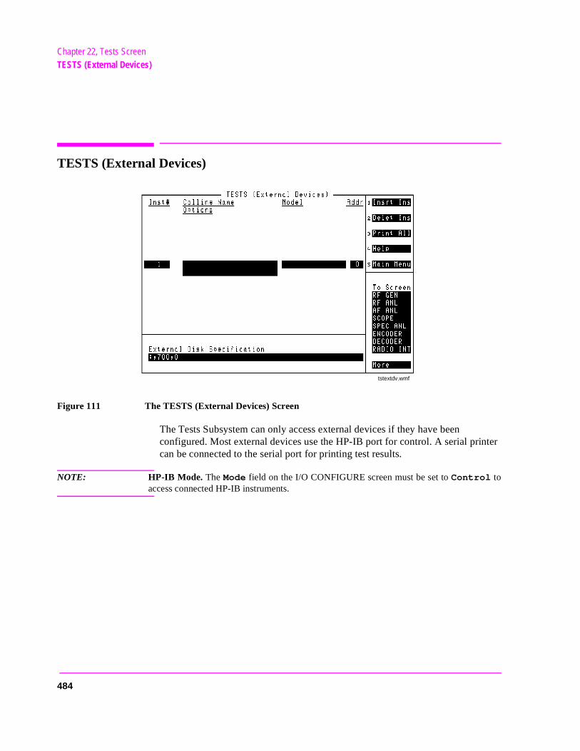
Chapter 22, Tests ScreenTESTS (External Devices)
TESTS (External Devices)
Figure 111 The TESTS (External Devices) Screen
The Tests Subsystem can only access external devices if they have been configured. Most external devices use the HP-IB port for control. A serial printer can be connected to the serial port for printing test results.
NOTE: HP-IB Mode. The Mode field on the I/O CONFIGURE screen must be set to Control toaccess connected HP-IB instruments.
tstextdv.wmf
484
Chapter 22, Tests ScreenTESTS (External Devices)
ents,
t to
een.
t to
Addr
This field is used to enter the instrument’s remote address. For HP-IB instrumenter the full 3-digit address (such as 704).
Calling Name
The Calling Name field is used to enter the instrument’s function (in upper-case letters). For example, PRINTER, POWER SUPPLY, DATA COLLECTION (disk drive), and so forth.
Delet Ins
This field allows you to delete an instrument from the list at the bottom of thescreen.
Use the knob, up-arrow, or down-arrow key to select the step where you wandelete an instrument.
External Disk Specification
This field is used when storing and loading procedures on an external disk.
Operating Considerations
The HP-IB path entered in the External Disk Specification field is used by the Select Procedure Location: field on the TESTS (Main Menu) screen when Disk is selected.
Insrt Ins
This field allows you to enter an instrument in the list at the bottom of the scr
Use the knob, up-arrow, or down-arrow key to select the step where you waninsert an instrument.
See Also
Programmer’s Guide
485
Chapter 22, Tests ScreenTESTS (External Devices)
c
ns,
ere
Inst#
The Inst# field lists the number of external devices that are configured for the tests in the current procedure.
Main Menu
Selecting this field returns you to the TESTS (Main Menu) screen.
Model
This field is used to enter the instrument’s model number. There is no specifisyntax for entering model numbers into this field.
Options
This field is used to enter the instrument’s option number or numbers if any.
Operating Considerations
This field may be left blank, or otherwise may include other calling name optiofor example:
Printer options – LN=#,START,END
Where # is the number of lines on each page. Where START causes a form feed at the start of each printout. Where END causes a form feed at the end of each printout.
Data collection options – NN Where NN is the number of records (file size) for the mass-storage location whdata will be collected on disk or memory card. The default record size is 80.
Print All
This field allows you to print the Test Set’s screen image.
486
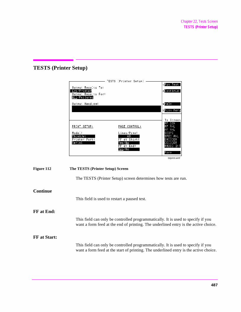
Chapter 22, Tests ScreenTESTS (Printer Setup)
TESTS (Printer Setup)
Figure 112 The TESTS (Printer Setup) Screen
The TESTS (Printer Setup) screen determines how tests are run.
Continue
This field is used to restart a paused test.
FF at End:
This field can only be controlled programmatically. It is used to specify if you want a form feed at the end of printing. The underlined entry is the active choice.
FF at Start:
This field can only be controlled programmatically. It is used to specify if you want a form feed at the start of printing. The underlined entry is the active choice.
tstprint.wmf
487
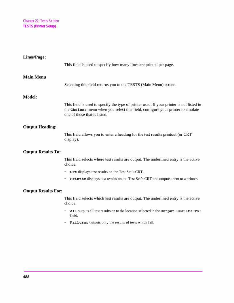
Chapter 22, Tests ScreenTESTS (Printer Setup)
er.
Lines/Page:
This field is used to specify how many lines are printed per page.
Main Menu
Selecting this field returns you to the TESTS (Main Menu) screen.
Model:
This field is used to specify the type of printer used. If your printer is not listed in the Choices menu when you select this field, configure your printer to emulate one of those that is listed.
Output Heading:
This field allows you to enter a heading for the test results printout (or CRT display).
Output Results To:
This field selects where test results are output. The underlined entry is the active choice.
• Crt displays test results on the Test Set’s CRT.
• Printer displays test results on the Test Set’s CRT and outputs them to a print
Output Results For:
This field selects which test results are output. The underlined entry is the active choice.
• All outputs all test results on to the location selected in the Output Results To: field.
• Failures outputs only the results of tests which fail.
488
Chapter 22, Tests ScreenTESTS (Printer Setup)
Printer Address:
This field is used to specify the address of an HP-IB printer. This field is only displayed if the Printer Port: field is set to HP-IB.
Printer Port:
This field is used to select the port your printer is connected to.
Run Test
Selecting this field loads and runs the test chosen in the Select Procedure Filename: field on the TESTS (Main Menu) screen.
489
Chapter 22, Tests ScreenTESTS (IBASIC Controller)
TESTS (IBASIC Controller)
Figure 113 The TESTS (IBASIC Controller) Screen
The IBASIC controller is used to run IBASIC programs. This screen is also used as a stand-alone IBASIC computer. See the Instrument BASIC documentation for information about writing your own tests for the Test Set.
If you need to perform a simple IBASIC operation, such as a SAVE or GET function, you can enter commands one at a time. To do this, access the TESTS (IBASIC Controller) screen and use the knob to enter commands.
Refer to the Programmer’s Guide for information about using the TESTS (IBASIC Controller) screen to write and store your own tests.
tstibasc.wmf
490
Chapter 22, Tests ScreenTESTS (IBASIC Controller)
Clr Scr
This field is used to clear the IBASIC controller screen.
Continue
This field is used to restart a paused test.
Main Menu
Selecting this field returns you to the TESTS (Main Menu) screen.
Run
Selecting this field runs the IBASIC program.
Sngl Step
This field (single step) allows you to step through an IBASIC program line-by-line.
491
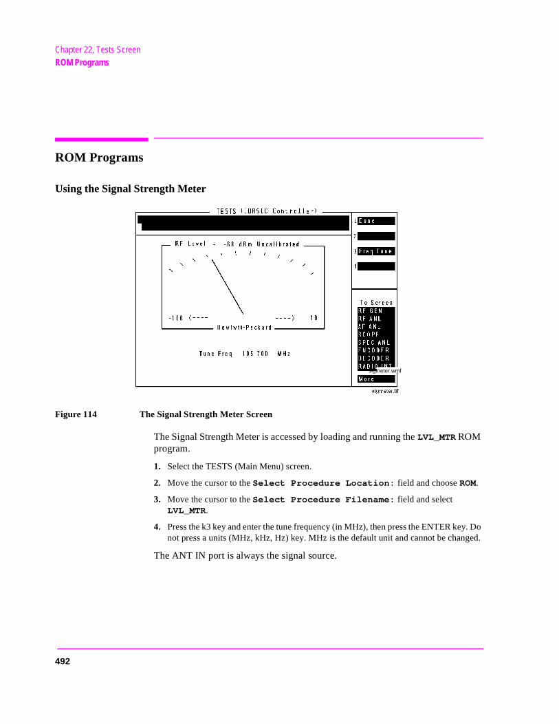
Chapter 22, Tests ScreenROM Programs
ROM Programs
Using the Signal Strength Meter
Figure 114 The Signal Strength Meter Screen
The Signal Strength Meter is accessed by loading and running the LVL_MTR ROM program.
1. Select the TESTS (Main Menu) screen.
2. Move the cursor to the Select Procedure Location: field and choose ROM.
3. Move the cursor to the Select Procedure Filename: field and select LVL_MTR.
4. Press the k3 key and enter the tune frequency (in MHz), then press the ENTER key. Do not press a units (MHz, kHz, Hz) key. MHz is the default unit and cannot be changed.
The ANT IN port is always the signal source.
sigmeter.wmf
492
Chapter 22, Tests ScreenROM Programs
ro--
ro-
d
Securing a Test Procedure
The password option for securing a test procedure is accessed by loading and running the SECURE_IT ROM program. This program is accessed by running the IB_UTIL program.
The password option for securing a test procedure is accessed by loading and running the SECURE_IT ROM program. This program is accessed by directly selecting it from the Choices menu.
1. Select the TESTS (Main Menu) screen.
2. Select the Select Procedure Location: field and choose ROM.
3. Select the Select Procedure Filename: field.
• Select SECURE_IT from the list of programs. Press Run Test to run the proce-dure; follow the directions to secure the desired information.
• Select IB_UTIL from the list of programs. Press Run Test to display a list of pcedures; select SECURE_IT and follow directions to secure the desired information.
Clearing RAM
RAM can be cleared using the RAM_MNG program in the Test Set’s ROM. This program clears all RAM, including any SAVE/RECALL registers saved to Internal (see the Save/Recall field description, on page 387 in the I/O CONFIGURE screen description).
This program is accessed by running the IB_UTIL program.
This program is accessed by directly selecting it from the Choices menu.
1. Select the TESTS (Main Menu) screen.
2. Select the Select Procedure Location: field and choose ROM.
3. Select the Select Procedure Filename: field.
• Select RAM_MNG from the list of programs. Press Run Test to run the procedure; follow directions to clear RAM.
• Select IB_UTIL from the list of programs. Press Run Test to display a list of pcedures; select RAM_MANAGER and follow directions to clear RAM.
To preserve the SAVE/RECALL registers, don’t use the RAM_MNG program. Instead, load a different test program to clear the previous test from RAM, anthen reload the desired test.
493

Chapter 22, Tests ScreenROM Programs
494
23
TX Test Screen
495
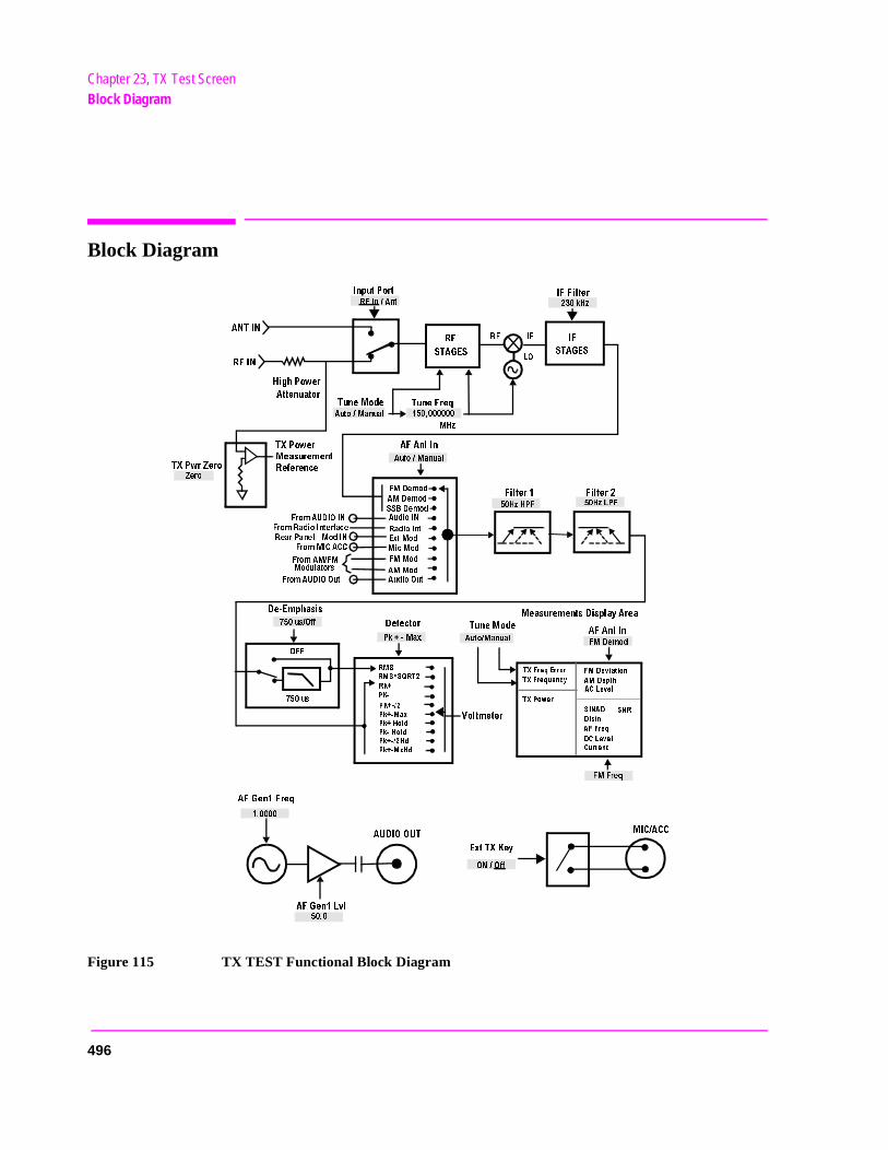
Chapter 23, TX Test ScreenBlock Diagram
Block Diagram
Figure 115 TX TEST Functional Block Diagram
!.4).
2&).
)NPUT0ORT
(IGH0OWER
!TTENUATOR
4UNE-ODE
4UNE&REQ
480WR:ERO
:ERO
480OWER
-EASUREMENT
2EFERENCE
&-$EMOD
!-$EMOD
33"$EMOD
!UDIO).
2ADIO)NT
%XT-OD
-IC-OD
&--OD
!--OD
!UDIO/UT
&ROM!5$)/).
&ROM2ADIO)NTERFACE
2EAR0ANEL -OD).
&ROM-)#!##
&ROM!-&-
-ODULATORS
&ROM!5$)//UT
$E %MPHASIS
US/FF
/&&
&ILTER &ILTER
!&!NL)N
!&!NL)N
4UNE-ODE
-EASUREMENTS$ISPLAY!REA
-(Z
!UTO-ANUAL
(Z(0&
(Z,0&
!UTO-ANUAL
2& )&
,/
2&
34!'%3
)&
34!'%3
2&)N!NT
)&&ILTER
K(Z
US
$ETECTOR
2-3
2-33124
2+
0+
0+
0K -AX
!UTO-ANUAL
6OLTMETER
&-$EMOD
0K -AX
0K(OLD
0K (OLD
0K (D
0K -X(D
&-&REQ
/./FF
!&'EN&REQ
!5$)//54
%XT48+EY
-)#!##
!&'EN,VL
48&REQ%RROR
48&REQUENCY
480OWER
&-$EVIATION
!-$EPTH
!#,EVEL
3).!$
3.2
$ISTN
!&&REQ
$#,EVEL
#URRENT
496
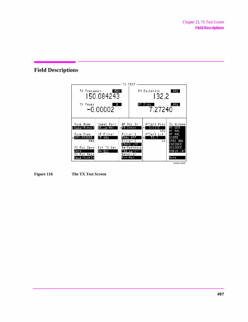
Chapter 23, TX Test ScreenField Descriptions
Field Descriptions
Figure 116 The TX Test Screen
txscrn.wmf
497

Chapter 23, TX Test ScreenField Descriptions
AF Anl In
Audio Frequency Analyzer input selects the input for the analyzer. When selected, this field displays a list of choices.
Signals can be analyzed from three different types of inputs:
• The output of the AM, FM, or SSB demodulators. • The AUDIO IN, RADIO INTERFACE, MODULATION INPUT, MIC/ACC, and
AUDIO OUT connectors.
The signal present at the AM or FM modulators for the RF Generator.
Operating Considerations
Changing this field alters the upper AF measurement to the appropriate measurement type.
This is a priority control field. Accessing the RX TEST or TX TEST screen overrides any changes made to this field in other screens.
See Also
"Interaction Between Screens" on page 54"Displaying Measurements" on page 57
498
Chapter 23, TX Test ScreenField Descriptions
en1
the
AF Freq
This is the default measurement for this measurement field. Selecting this field displays the following measurement choices:
SINAD Distortion SNR (Signal to Noise Ratio) AF Frequency DC Level
Current - DC only
Operating Considerations
This is a priority control field. Accessing the RX TEST or TX TEST screen overrides any changes made to this field in other screens.
SNR Operation• Selecting SNR turns off the other audio measurement. • The RF Generator and AFGen1 must be set up to provide the radio’s carrier. (AFG
is automatically turned on and off repeatedly during this measurement.) • AFGen2 must be turned off. • The radio’s receiver’s audio output must be connected to the AUDIO IN port (set
AF Anl In field to Audio In).
See Also
"Interaction Between Screens" on page 54"Displaying Measurements" on page 57
499
Chapter 23, TX Test ScreenField Descriptions
AFGen1 Freq
This Audio Frequency Generator control sets the frequency for the first audio frequency sinewave generator.
AFGen1 Lvl
This Audio Frequency Generator control sets the level out the AUDIO OUT connector in volts rms (across a low-impedance output), or in mW, W, or dBm across a 600-ohm load (mW is selected by pressing [SHIFT], [ENTER]).
Operating Considerations
In the TX TEST screen, the signal is always output through the AUDIO OUT connector.
Current
The Current field is found by selecting the SINAD field on the Test Set display of the TX TEST screen. This field only displays the DC current measured at the DC input port on the back of the Test Set. Any offset can be removed by selecting Zero from the DC Current field.
DC Level
This field displays the DC voltage entering at the DC input port on the back of the Test Set.
De-Emphasis
This setting selects or bypasses the 750 ms de-emphasis networks in the audio analyzer and speaker circuitry.
Operating Considerations
This is a priority control field. Accessing the RX TEST or TX TEST screen overrides any changes made to this field in other screens.
See Also
"Interaction Between Screens" on page 54
500
Chapter 23, TX Test ScreenField Descriptions
e
eset. same
eset. same
ET
value ferent
Detector
This setting selects the type of detector used when measuring and displaying AF signal levels.
Detector Types• RMS displays the RMS value of signals. • RMS*SQRT2 displays the RMS value of a signal multiplied by . • Pk+ displays the positive peak value. • Pk− displays the negative peak value. • Pk±/2 adds the positive and negative peak values and divides the sum by 2. • Pk±Max compares the positive and negative peaks and displays the greater valu
(polarity is not indicated). • Pk+ Hold displays and holds the positive peak value until the measurement is r
To reset, press the MEAS RESET key, or select a different detector, or reselect thedetector.
• Pk− Hold displays and holds the negative peak value until the measurement is rTo reset, press the MEAS RESET key, select a different detector, or reselect thedetector.
• Pk±/2 Hold divides the sum of the positive and negative peak values by 2, anddisplays the value until the measurement is reset. To reset, press the MEAS RESkey, select a different detector, or reselect the same detector.
• Pk±Mx Hold compares the positive and negative peaks and displays the greater until the measurement is reset. To reset, press the MEAS RESET key, select a difdetector, or reselect the same detector.
Operating Considerations
This is a priority control field. Accessing the RX TEST or TX TEST screen overrides any changes made to this field in other screens.
See Also
"Interaction Between Screens" on page 54
2
501
Chapter 23, TX Test ScreenField Descriptions
r
here
Distn
This field displays the percent of distortion. The Distortion measurement is only for a 1 kHz signaling tone.
Ext TX Key
This field controls a switch at the MIC/ACC connector. Its intended use is to “key” an external transmitter.
See Also
Figure 117 on page 516
Filter 1 and Filter 2
Filters 1 and 2 select a variety of standard and optional filters. Selecting eithefield lists the choices available for that field.
See Also
Chapter 5, "AF Analyzer Screen"
FM Deviation
This is the default measurement for this field. The type of measurement listedis dependent on the AF Anl In settings.
See Also
AF Anl In field description, on page 498"Displaying Measurements" on page 57
IF Filter
This field selects the desired IF filter’s bandwidth for modulated signals beinganalyzed.
502
Chapter 23, TX Test ScreenField Descriptions
TX wer
Input Port
This field selects the RF IN/OUT or ANT IN port for making RF measurements. The RF IN/OUT port must be used for making TX Power measurements on this screen.
Operating Considerations
Maximum signal levels at each port are printed on the front panel.
If the RF power at the RF IN/OUT port exceeds allowable limits, a loud warning signal sounds and a message appears at the top of the screen. If this occurs, disconnect the RF power, press the MEAS RESET key, and allow the Test Set to cool off for approximately 2 minutes before making any other measurements on this port.
The ANT IN (antenna input) connector provides a highly-sensitive input for very low-level signals (such as “off the air” measurements). You cannot measure (RF) Power on this screen using the antenna port. However, low-level RF poat the antenna port can be measured using theSpectrum Analyzer.
CAUTION: Connecting a signal of >200 mW to the ANT IN port can cause instrument damage.
If the overpower circuit is triggered (signified by a warning message at the top ofthe screen), remove the signal from the ANT IN port, and press the MEAS RESET key or turn the Test Set off and on to reset it.
RF Channel
The RF Channel field is displayed only when the RF Display field is set to Chan on the CONFIGURE screen.
This field displays the current channel number. Channel tuning eliminates theneed to transmit and receive frequencies directly into the Test Set. Once theradio’s RF channel standard is selected, you only have to enter the channel number to automatically set the RF Generator and RF Analyzer to the correct frequency.
Operating Considerations
To utilize the correct transmit and receive frequencies select the appropriate channel standard from the RF Chan Std field on the CONFIGURE screen.
503
Chapter 23, TX Test ScreenField Descriptions
SINAD
This field is only visible when SINAD is selected from the AF Freq field on the display area of the TX TEST screen. This field displays the measured SINAD of the input signal.
Tune Freq
RF Analyzer tune frequency sets the center frequency for the RF signal to be analyzed.
Operating Considerations
If the Tune Mode is set to Auto, the frequency is set by the Test Set by finding the strongest RF signal above −36 dBm within the full bandwidth of the RF Analyzer.
If the Tune Mode is set to Manual, the operator must enter the desired frequency.
See Also
Tune Mode field description (this page)
Tune Mode
This field selects automatic or manual tuning of the RF Analyzer.
Auto causes the RF Analyzer to find the signal with the greatest amplitude>-36 dBm, and set the tune frequency for that signal.
Manual requires the operator to set the tune frequency for the RF signal to be analyzed.
Operating Considerations
Changing the Tune Mode also changes the RF frequency display. Automatic tuning enables the TX Frequency measurement. Manual tuning enables the TX Freq Error measurement.
After autotuning to the desired signal, select Manual to prevent the Tune Freq from changing when the signal is no longer applied.
504
Chapter 23, TX Test ScreenField Descriptions
TX Freq Error,TX Frequency
This measurement area is used to display transmitter frequency error or transmitter frequency.
See Also
Tune Mode field description (this page)
TX Power
Transmitter power measures RF power at the RF IN/OUT port.
Operating Considerations
Maximum signal levels at each port are printed on the front panel.
Only the RF IN/OUT port can be used for measuring TX Power on this screen. When the Input Port is set to Ant, four dashes (- - - -) appear in place of digits for this measurement.
Use the Spectrum Analyzer to measure low-level RF power (≤200 mW) at the ANT IN port.
CAUTION: Connecting a signal of >200 mW to the ANT IN port can cause instrument damage (althoughinternal protection circuits can typically withstand a short-duration signal of 1 or 2 Watts).
If the overpower circuit is triggered (signified by a warning message at the top ofthe screen), remove the signal from the ANT IN port, and press the MEAS RESET key or turn the Test Set off and on to reset it.
See Also
Input Port field description, on page 503 (Operating Considerations) TX Power field description (this page)TX Power field description, on page 426TX Pwr Zero field description, on page 427
505
Chapter 23, TX Test ScreenField Descriptions
TX Pwr Zero
The transmitter power zero function establishes a 0.0000 W reference for measuring RF power at the RF IN/OUT port.
CAUTION: RF power must not be applied while zeroing. Set the RF GENERATOR screen Amplitudefield to off to prevent internal cross-coupling into the power detector while zeroing
Operating Considerations
When power is applied to the RF IN/OUT connector, the temperature of the internal circuitry increases. This can cause changes in the TX Power measurement when low power levels are measured immediately following high power measurements.
When alternately making high and low power measurements, always zero the power meter immediately before making the low-power measurements; this provides the best measurement accuracy.
506
24
Connector, Key, and Knob Descriptions
507
Chapter 24, Connector, Key, and Knob DescriptionsConnector Descriptions
Connector Descriptions
ANT IN
The antenna input is used for analyzing low-power RF signals (≤200 mWatts), and is typically used for off-the-air measurements. This port can be selected in the TX TEST, DUPLEX TEST, RF ANALYZER, or SPECTRUM ANALYZER screens.
CAUTION: Connecting a signal of >200 mW to the ANT IN port can cause instrument damage(although internal protection circuits can typically withstand a short-duration signalof 1 or 2 Watts).
If the overpower circuit is triggered (signified by a warning message at the top ofthe screen), remove the signal from the ANT IN port, and press [MEAS RESET]or turn the Test Set off and on to reset it.
Operating Considerations
Input impedance = 50Ω
TX Power cannot be measured using this port; use the RF IN/OUT port. However, low power levels can be measured using this port with the Spectrum Analyzer.
Additional sensitivity for this port is available using the Sensitivity field in the RF ANALYZER and SPECTRUM ANALYZER screens.
508
Chapter 24, Connector, Key, and Knob DescriptionsConnector Descriptions
F AN-
t
AUDIO IN
Two connectors are used to input audio signals to the AF Analyzer:
• HI is the main audio signal input connection.
• LO is used for the audio signal reference. Three choices are available using the AALYZER screen’s Audio In Lo field:
• Gnd connects the center pin through approximately 100Ω to chassis ground. • Float is a floating input.• 600 To Hi provides a 600Ω internal load to match an audio source with an outpu
impedance of 600Ω.
The measured level is the potential between the HI and LO center pins. The shells of both connectors are at chassis ground.
Operating Considerations
Input impedance is switchable between 1 MΩ in parallel with 95pF, or 600Ω floating.
This port is selected as the AF Analyzer’s input using the AF Anl In field in the TX TEST screen, DUPLEX TEST screen, AF ANALYZER screen, and various encoder modes. This port is always the AF Analyzer’s input when the RX TEST screen is displayed.
Signals input to the AF Analyzer are routed through different filters, amplifiers, and detectors that affect the displayed measurement.
CAUTION: The maximum level between the HI and LO center pins is 42 V peak (approximately 30 Vrms). Exceeding this value can cause permanent instrument damage.
See Also
Chapter 5, "AF Analyzer Screen"
509
Chapter 24, Connector, Key, and Knob DescriptionsConnector Descriptions
AUDIO MONITOR OUTPUT
This connector provides an external output from various tap points in the AF Analyzer.
Operating Considerations
The Scope To field in the AF ANALYZER screen determines the source of this signal.
The level is not affected by the front-panel VOLUME knob.
Output impedance <1 kΩ
See Also
Chapter 5, "AF Analyzer Screen"
AUDIO OUT
This port is used to output signals from AF Generators 1 and 2, including the encoder functions.
Operating Considerations
The output level is set by the AF Generators and is not affected by the front-panel VOLUME control.
Output impedance <1Ω Maximum output current = 20 mA peakMaximum reverse voltage = 12 V peak
AC/DC coupling is selected using the Audio Out field. This field is available in the DUPLEX TEST screen, RF GENERATOR screen, and various encoder modes.
510
Chapter 24, Connector, Key, and Knob DescriptionsConnector Descriptions
,
to 10
Chassis Ground
The rear-panel chassis ground terminal provides a general chassis connection, as well as providing a safety ground when dc power is used.
WARNING: To prevent a potential shock hazard, always connect the chassis ground terminal to earth groundwhen operating this instrument from a dc power source.
CRT VIDEO OUTPUT
This connector provides a signal for using an external video monitor. The signal provides a duplicate of the Test Set’s screen.
Operating Considerations
A multi-sync monitor must be used to match the video sync rate of 19.2 kHz.Examples of this type of monitor include - Mitsubishi Diamond Scan, NEC 3DLeading Edge CMC-141M, and Sony CPD-1302.
DC CURRENT MEASUREMENT
These connectors are used in series with a DC supply and load to provide a 0amp DC current meter.
Operating Considerations
The dc current meter is designed to measure positive current (the connector’s polarity is marked on the rear panel). Negative current of ≤10 amps will not damage the instrument, but will cause inaccurate positive current measurements (due to magnetic memory within the current-sensing element).
To recalibrate the current meter after negative current has been applied:
1. Connect a 10 amp positive current.
2. Disconnect the current.
3. Access the AF ANALYZER screen.
4. Select the DC Current Zero field to zero the meter.
See Also
"Displaying Measurements" on page 57
511
Chapter 24, Connector, Key, and Knob DescriptionsConnector Descriptions
ellu- with
r.
DC INPUT
This female connector is used with a dc supply to provide power to the instrument. The male counterpart to this connector is included in the Connector Kit accessory. (See "Accessories" on page 535.)
The following HP parts can also be ordered to assemble the male counterpart to this connector:
Connector housing: 1251-4782 (1 required) Connector contacts: 1252-0385 (2 required)
WARNING: To prevent a potential shock hazard, always connect the chassis ground terminal to earth groundwhen operating this instrument from a DC power source.
Digital Test Connections
Control I/O, CW RF OUT, DET OUT, IQ RF IN, 114.3 MHz OUT
The following connectors are only used when an HP cellular adapter (such as an HP 83203B) is connected to the Test Set to perform digital modulation tests. These connectors are optional.
1. Control I/O provides control of the cellular adapter.
2. CW RF OUT routes the RF carrier to the cellular adapter. If a cellular adapter is not present, a jumper must be used to connect this port to the IQ RF IN port.
3. DET OUT routes the average power detector’s signal to the AUX DSP IN of the clar adapter for making average power measurements. This port may not be usedall models of cellular adapter.
4. IQ RF IN routes the RF carrier from the cellular adapter back into the Test Set. If a cel-lular adapter is not present, a jumper must be used to connect this port to the CW RF OUT port.
5. 114.3 MHz IF OUT provides the down-converted RF signal to the cellular adapte
512
Chapter 24, Connector, Key, and Knob DescriptionsConnector Descriptions
M
. It e
DUPLEX OUT
This connection is an output for the RF Generator and Tracking Generator.
Operating Considerations
Output impedance = 50Ω
The RF Generator’s output is selected in the Output Port field. This field is available in the RX TEST, DUPLEX TEST, RF GENERATOR, and SPECTRUANALYZER screens.
CAUTION: Connecting an RF source of >200 mW to this connector can permanently damage theinstrument.
EXT SCOPE TRIGGER INPUT
This connector provides an external oscilloscope trigger.
Operating Considerations
Input threshold approximately 2.5 V Maximum Input level approximately 20 V peakInput impedance is:
100 kΩ for signals ≤5.6 V peak 5 kΩ for signals >5.6 V peak
When measured with no load on the input, a 5 Volt level is present on the connector due to the internal pull-up resistor design.
See Also
Chapter 14, "Oscilloscope Screen"
HEADPHONE
This port furnishes an alternate audio monitor output from the speaker circuitallows you to listen to signals in a noisy environment (such as a cell site). Thfront-panel VOLUME knob controls the level.
Operating Considerations
Output impedance approximately 1 kΩ
513
Chapter 24, Connector, Key, and Knob DescriptionsConnector Descriptions
his
sen-
tic en’s
h as
Key
HP-IB
.
This connector allows communication between the Test Set and other instruments or computers using the Hewlett-Packard Interface Bus (HP-IB).
See Also
Chapter 12, "I/O Configure Screen"HP 8920 Programmer’s Guide
MEMORY CARD Slot
This front-panel opening is where memory cards are inserted.
See Also
HP 8920 Programmer’s Guide
MIC/ACC
This 8-pin DIN connector (see figure 117 on page 516) is used for several functions:
• Mic In is used to modulate the RF Generator when the KEY IN line is grounded. Tsignal is summed with the external MODULATION INPUT signal. The Mod In To field of the RF GENERATOR screen sets the type of modulation (AM or FM) and sitivity (%AM/Vpk or kHz/Vpk) for this connection.
• Key In provides control of the RF Generator’s output state (on or off) and automaswitching between the TX TEST and RX TEST screens (if the CONFIGURE screRX/TX Cntl functions are set to Auto and PTT). Screen switching occurs when thisline is grounded.
• Key Out 1 and Key Out 2 provide a switch path to control external equipment (suckeying a transmitter). Key Out 1 and Key Out 2 are connected when the Ext TX key field is set to On.
CAUTION: Do not exceed 50 Vdc (open circuit) or 250 mA dc (closed circuit) between Key Out 1 andOut 2. Damage to internal components may result.
514
Chapter 24, Connector, Key, and Knob DescriptionsConnector Descriptions
one
To Use the Microphone
To modulate the RF Generator using the optional microphone (HP part number 08920-61059):
1. Connect the microphone to the MIC/ACC connector.
2. Access the RF GENERATOR screen.
3. Enter the carrier frequency in the RF Gen Freq field.
4. Enter the RF Generator’s Amplitude.
5. Select the Output Port (RF IN/OUT or DUPLEX OUT).
6. Connect the selected output port to your receiver or antenna.
7. Using the Mod In To field,
• select the type of modulation: FM (/Vpk)
• enter the modulation sensitivity to a 1 Vpeak signal (usually 1 kHz for microphuse). See "Mod In To" on page 435.
8. Key the microphone to transmit.
MIC/ACC Operating Considerations
Mic In specifications
Input impedance = 100 kΩ Maximum input level = 10 V peak Full scale input = 10 mV Bandwidth is limited to 3 kHz.
The Mic In signal is filtered and amplified to provide a stable deviation-limited signal to the RF Generator.
750 µs microphone pre-emphasis is selected in the RF GENERATOR screen.
515
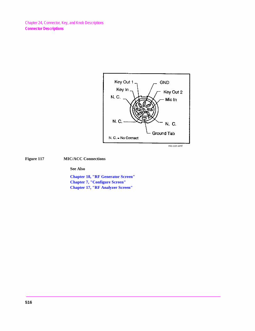
Chapter 24, Connector, Key, and Knob DescriptionsConnector Descriptions
Figure 117 MIC/ACC Connections
See Also
Chapter 18, "RF Generator Screen"Chapter 7, "Configure Screen"Chapter 17, "RF Analyzer Screen"
mic-con.wmf
516
Chapter 24, Connector, Key, and Knob DescriptionsConnector Descriptions
MODULATION INPUT
This connector provides an external modulation connection to the RF Generator.
Operating Considerations
Input impedance = 600Ω Maximum input level = 12 V peak Full scale input = 1 V peak
The Mod In To field of the RF GENERATOR screen sets the type of modulation (AM or FM) and sensitivity (%AM/Vpk or kHz/Vpk) for this connection.
This signal is summed with the microphone MIC IN signal from the MIC/ACC connector.
The FM Coupling field in the RF GENERATOR, DUPLEX TEST, and various encoder modes selects ac or dc coupling of this signal for FM operation.
Parallel Port
This port is used with printers requiring a parallel interface when printing screen images or test results. Set the Printer Port: field (on the PRINT CONFIGURE screen or TESTS (Printer Setup) screen) to Parallel to print to this port. Use address 15 when sending data to this port from IBASIC programs.
Pin numbers are embossed on the connector. Pin assignments are as follows:
517
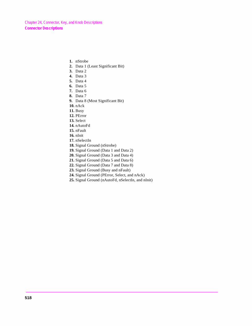
Chapter 24, Connector, Key, and Knob DescriptionsConnector Descriptions
1. nStrobe 2. Data 1 (Least Significant Bit) 3. Data 2 4. Data 3 5. Data 4 6. Data 5 7. Data 6 8. Data 7 9. Data 8 (Most Significant Bit) 10. nAck 11. Busy 12. PError 13. Select 14. nAutoFd 15. nFault 16. nInit 17. nSelectIn 18. Signal Ground (nStrobe) 19. Signal Ground (Data 1 and Data 2) 20. Signal Ground (Data 3 and Data 4) 21. Signal Ground (Data 5 and Data 6) 22. Signal Ground (Data 7 and Data 8) 23. Signal Ground (Busy and nFault) 24. Signal Ground (PError, Select, and nAck) 25. Signal Ground (nAutoFd, nSelectIn, and nInit)
518
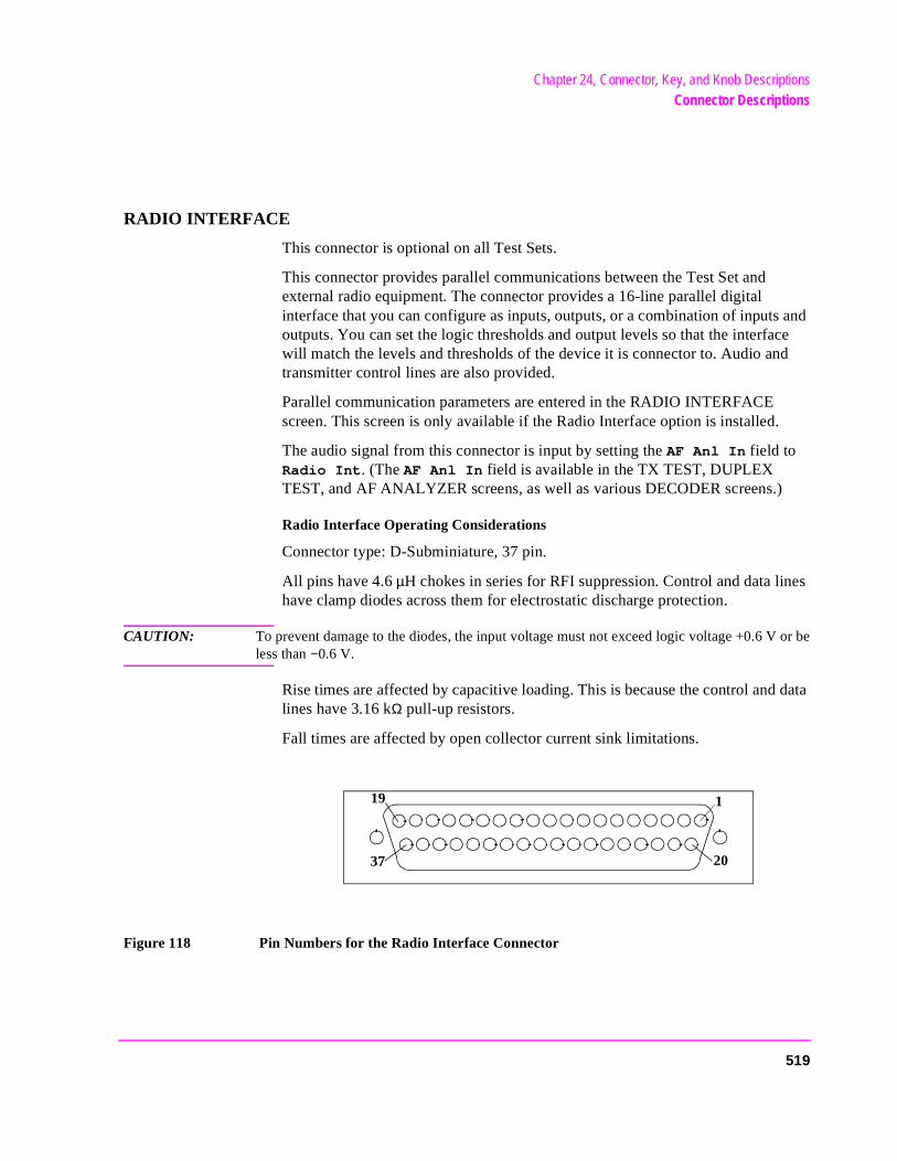
Chapter 24, Connector, Key, and Knob DescriptionsConnector Descriptions
RADIO INTERFACE
This connector is optional on all Test Sets.
This connector provides parallel communications between the Test Set and external radio equipment. The connector provides a 16-line parallel digital interface that you can configure as inputs, outputs, or a combination of inputs and outputs. You can set the logic thresholds and output levels so that the interface will match the levels and thresholds of the device it is connector to. Audio and transmitter control lines are also provided.
Parallel communication parameters are entered in the RADIO INTERFACE screen. This screen is only available if the Radio Interface option is installed.
The audio signal from this connector is input by setting the AF Anl In field to Radio Int. (The AF Anl In field is available in the TX TEST, DUPLEX TEST, and AF ANALYZER screens, as well as various DECODER screens.)
Radio Interface Operating Considerations
Connector type: D-Subminiature, 37 pin.
All pins have 4.6 µH chokes in series for RFI suppression. Control and data lines have clamp diodes across them for electrostatic discharge protection.
CAUTION: To prevent damage to the diodes, the input voltage must not exceed logic voltage +0.6 V or beless than −0.6 V.
Rise times are affected by capacitive loading. This is because the control and data lines have 3.16 kΩ pull-up resistors.
Fall times are affected by open collector current sink limitations.
Figure 118 Pin Numbers for the Radio Interface Connector
19 1
2037
519
Chapter 24, Connector, Key, and Knob DescriptionsConnector Descriptions
cted
out-ll as
Out ts nects
s
esent
The pin numbers for the radio interface connector are listed on the connector and in figure 118 on page 519. Pin assignments are as follows:
1. GND 2. No Connection 3. Audio Out
• This is an output for the audio sources, AF Gen1 and AF Gen2. It it also connein parallel to the front-panel AUDIO OUT connector.
• Set the AFGen1 To field, the AFGen2 To field, or both to Audio Out to select this pin and the front-panel AUDIO OUT connector as the audio sourceput. These fields are found on the RX TEST and DUPLEX TEST screens as weon the signalling encoder screen.
• All settings for the audio source affect the signal at this pin.• Output specifications are the same as the front-panel AUDIO OUT connector.
4. Key Out 2 • This pin is a key relay contact.• Key Out 1 and Key Out 2 are connected in parallel with the Key Out 1 and Key
2 pins of the front-panel MIC/ACC connector. They go to internal relay contacand can be used to key a transmitter. The relay contacts are closed, which conthe two pins when the Ext TX Key field is set to On. This field can be found on the TX TEST, DUPLEX TEST, or RF ANALYZER screen. (See "MIC/ACC" on page 514.)
• Capacitance is 0.1 µF per pin (300 pF per pin after approximately 6 µs).Contact Rating is 0.5 A, 50 V.
5. Audio Input • Set the AF Anl In field to Radio Int to select this pin as the audio analyzer’
input. This field is found on the TX TEST, DUPLEX TEST, or AF ANALYZER screen, as well as various signalling decoder screens.
• Input impedance is 100 kΩ.6. Key Out 1
• See pin 4. Also see "MIC/ACC" on page 514. 7. −12.6 V
• Pins 7 and 8 can supply power to a low current device. The voltage is always prwhen the Test Set is powered on and cannot be varied or turned on or off.
• Output current is limited by an internal 100Ω, 2 W resistor.8. +12.6 V
• See pin 7.
520
Chapter 24, Connector, Key, and Knob DescriptionsConnector Descriptions
sh-
I (1) e
many
data
time, The
ns.
rmed
pt
the n be l-) in-
9. Logic Voltage (data level): • The voltage on this pin determines the high output voltage and input logic thre
olds of the parallel data, strobe, and interrupt pins.• Either +12 volts or +5 volts is supplied by the radio under test to indicate the H
logic level it uses for serial/parallel communications. If no signal is supplied, thlogic level defaults to 5 volts.
• The load that this pin presents to an external voltage source depends on how lines are pulled low.
• Input range is 5.1 to 20 V dc.Load at maximum current (all lines pulled low) is 145Ω.
10. No connection11. Parallel Strobe Out
• This pin outputs a digital pulse to indicate when data is output on the parallel pins.
• The leading edge occurs when the pins change state. But, to allow for settling the external device should latch on the level of the pulse or the trailing edge. strobe can be set to go high or low with the Strobe Pol field on the RADIO INTERFACE screen.
• The output level and current sink capability is the same as the parallel data piStrobe pulse width is 5 µs (typical).Logic Sense is programmable high or low.
12. Interrupt Input 1• The interrupt lines can be used together or independently. The lines must be a
for the Test Set to sense an interrupt. This is done in the Interrupt 1 or In-terrupt 2 fields on the RADIO INTERFACE screen. When an armed interruis pulled low, the Interrupt 1 or Interrupt 2 fields will show that the in-terrupt is Tripped. The interrupt can only be cleared when the line returns to high state and the interrupt is armed again. The status of the interrupt lines caread from the RADIO INTERFACE screen or by an HP-IB or IBASIC program. Aso, one of the interrupts can be designated as the HP-IB service request (SRQdicator.
• Logic is active low.Input impedance is internally pulled-up to the logic voltage through 100 kΩ.Logic threshold is the same as the parallel data pins.
13. Interrupt Input 2 • See pin 14.
14. No Connection
521
Chapter 24, Connector, Key, and Knob DescriptionsConnector Descriptions
the in 9).
state to be
15. Parallel Data In/Out• You can designate these pins as outputs or inputs with the I/O CONFIG field of
the RADIO INTERFACE screen. Pins designated as inputs are pulled high byTest Set. Output level and input logic thresholds are set by the logic voltage (p
• Pin 19 is LSB, Pin 34 is MSB. • High level output is Logic Voltage through a 3.16 kΩ pull-up resistor.
Output current sink (TTL low, voltage ≤ 1.5 V) is 6 mA minimum, 16 mA typicalInput data logic threshold is (Logic Voltage − 0.7 V) × 0.34The default Logic Voltage is 5.1 V.
• Read back on the data bus is accomplished by setting all data lines to the highand then having the user pull appropriate data lines low according to the data read back.
16. No Connection.
See Also
Chapter 16, "Radio Interface Screen".
RF IN/OUT
This Type-N connection is used to output signals from the RF Generator and to input RF signals.
CAUTION: Overpower Damage — Refer to the Test Set’s front panel for maximum input powerlevel. Exceeding this level can cause permanent instrument damage.
If the RF power at the RF IN/OUT port exceeds allowable limits, a loud warningsignal sounds and a message appears at the top of the screen. If this occurs,disconnect the RF power, press [MEAS RESET], and allow the Test Set to cooloff for approximately 2 minutes before making any other measurements on thisport.
Operating Considerations
This port must be used when measuring TX (RF) Power.
Signals ≤200 mWatts can be input to the ANT IN connector for all RF measurements except TX Power.
This port can be selected in the TX TEST, DUPLEX TEST, RF ANALYZER, or SPECTRUM ANALYZER screens.
See Also
"Displaying Measurements" on page 57.
522
Chapter 24, Connector, Key, and Knob DescriptionsConnector Descriptions
u aree
cablein the
SERIAL PORT
This 6-pin, RJ-11, dual serial port is used to input and output serial data for entering programs, printing tests results and screen images, and sending test results to a connected controller, disk drive, or terminal.
Operating Considerations
The serial communications settings are defined on the I/O CONFIGURE screen.
NOTE: Using Port B. The second serial port (B) is only used with IBASIC programs to communicatewith base stations or other equipment when the primary serial port is used for printing or datacollection. Port B cannot be used for printing screens, and its communication settings can onlybe changed using IBASIC commands (listed in the Programmer’s Guide). Unless yowriting IBASIC programs that require serial printing and other serial data transfer at the samtime, we recommend that you only use the primary port (A).
The IBASIC Controller sends and receives data to the serial ports using address 9 for the primary port, and 10 for Port B. For example, to enter data from the primary serial port into a program variable named SDATA, you could use the following command:
ENTER 9;SDATA
To send data from your program out of the primary serial port, you could use the following command:
OUTPUT 9;SDATA
Use an RJ-11, 25-pin, RS-232 adapter (HP P/N 98642-66508) and RJ-11 cable (HP P/N 98642-66505) to connect the Test Set to a serial printer, terminal, or computer.
NOTE: RJ-11 Connectors. RJ-11 cables and adapters can be wired several ways. If you buy a or adapter other than the HP parts listed, verify the connections for the pins indicated following table before connecting cables to the instruments.
523
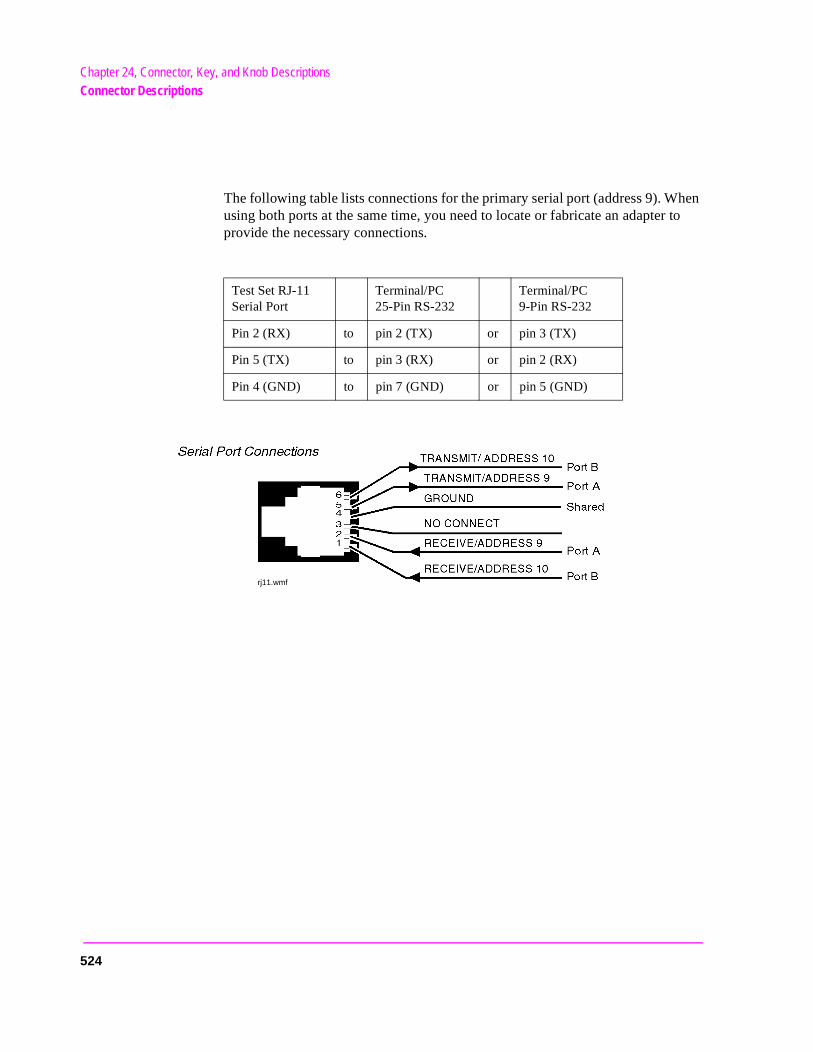
Chapter 24, Connector, Key, and Knob DescriptionsConnector Descriptions
The following table lists connections for the primary serial port (address 9). When using both ports at the same time, you need to locate or fabricate an adapter to provide the necessary connections.
Test Set RJ-11 Serial Port
Terminal/PC 25-Pin RS-232
Terminal/PC 9-Pin RS-232
Pin 2 (RX) to pin 2 (TX) or pin 3 (TX)
Pin 5 (TX) to pin 3 (RX) or pin 2 (RX)
Pin 4 (GND) to pin 7 (GND) or pin 5 (GND)
rj11.wmf
524
Chapter 24, Connector, Key, and Knob DescriptionsConnector Descriptions
d
10 MHz REF INPUT
This connection allows you to input an external reference.
Operating Considerations
Input frequency = 1, 2, 5, or 10 MHz Input level >0.15 V rms Input impedance approximately 50Ω.
When a valid signal is applied to the 10 MHz REF INPUT, the Test Set automatically switches from internal to external reference.
This signal is used as a reference for, and directly affects, these functions:
RF Generator Frequency (including the Tracking Generator)
RF Frequency Counter
AF Frequency Counter
RF Analyzer Tune Frequency
Spectrum Analyzer Center Frequency
AF Generators 1 and 2, and the decoder’s frequency counter, are not affecteusing an external reference; they use their own reference.
NOTE: The reference output frequency is always 10 MHz, independent of the selected input referencefrequency.
Electrostatic discharges to the 10 MHz REF INPUT port of 0.5 kV or above maycause degradation of performance requiring operator intervention.
10 MHz REF OUTPUT
This connector furnishes a 10 MHz reference for external instruments.
Operating Considerations
Waveform = sinewave Output frequency = 10 MHz Output level >0.5 V rms Output impedance approximately 50Ω.
NOTE: The reference output frequency is always 10 MHz, independent of the selected input referencefrequency.
525
Chapter 24, Connector, Key, and Knob DescriptionsKey Descriptions
-mea-.
(such
e for
Key Descriptions
DATA Keys
The DATA keys have four main uses:
• The [0] to [9], [ . ], [+/-], and A to F keys are for entering and changing values.
• [ENTER] is used to select a field or screen, and to enter numbers when the unit-ofsure is not specified. This function is identical to pressing the cursor-control knob
• [ON/OFF] is used to enable and disable measurements, and to turn numeric fieldsas Amplitude) on and off.
• YES and NO are used to confirm selected operations before they are executed.
• EEX ([SHIFT], [+/-]) is used for entering numbers using scientific notation.
• The remaining keys in this area are for entering and changing the unit-of-measurmeasurements or field entries.
See Also
"Entering and Changing Numbers" on page 63.
526
Chapter 24, Connector, Key, and Knob DescriptionsKey Descriptions
nt
are
s the
t k until
e for
tion asure-
DATA FUNCTIONS Keys
[INCR ³10], [INCR SET], and [INCR ×10] are used to change the increment or decremea value when changing field values.
• Up-arrow and down-arrow keys increment or decrement field values. These keysalso used to select alternate field entries without displaying the Choices menu used by some fields. They are also used to move the cursor in string entry fields (such aPrint Title field on the PRINT CONFIGURE screen).
• LO LIMIT ([SHIFT], down-arrow key) and HI LIMIT ([SHIFT], up-arrow key) and semeasurement end points. Exceeding the end points causes screen prompts to blinthey are reset.
REF SET ([SHIFT], [INCR ³10]) is used to enter or remove a measurement referencrelative AF and RF measurements.
METER ([SHIFT], [INCR SET]) enables or disables the analog bar-graph meter funcfor measurements using large digits (such as the RX TEST and TX TEST screen mements).
AVG ([SHIFT], [INCR ×10]) enables or disables measurement averaging.
See Also
"Operating Overview" on page 53.
527
Chapter 24, Connector, Key, and Knob DescriptionsKey Descriptions
ure- are in
gh are
s
ime
INSTRUMENT STATE Keys
[LOCAL] returns the instrument to manual control after HP-IB control is used.
• [RECALL] lists any instrument setups that were saved.
• [MEAS RESET] clears the measurement “history” for all of the instrument’s measment algorithms (such as the averaging function) to restart all measurements thatprogress.
• [PRESET] restores most instrument settings to their factory default states, (althoumost CONFIGURE screen changes are not affected). Instrument self-diagnosticsnot run at this time.
• ADRS ([SHIFT], [LOCAL]) displays the HP-IB address of the Test Set.
• SAVE ([SHIFT], [RECALL]) stores instrument setups.
See Also
"Saving and Recalling Instrument Setups" on page 71.
SCREEN CONTROL Keys
[RX], [TX], [DUPLEX], [TESTS], MSSG, HELP, and CONFIG access several instru-ment control and information screens.
• [PREV] accesses the previous screen.
• HOLD ([SHIFT], [PREV]) stops all measurements. Selecting HOLD again resumemeasurements.
• PRINT ([SHIFT], [TESTS]) prints the entire contents of the displayed screen, the tand date, and any Print Title defined in the PRINT CONFIGURE screen.
See Also
"Printing A Screen" on page 66.
528
Chapter 24, Connector, Key, and Knob DescriptionsKey Descriptions
as
am. not
um-
ower
t-er is
Miscellaneous Keys and Buttons
• [SHIFT] is used to select the blue-labeled functions listed above some keys (suchPRINT, CONFIG, RELEASE, EEX and so forth).
• [CANCEL] is used to cancel an entry in progress, or to stop a running IBASIC progrFor example, if you press [RECALL] to recall an instrument setup, and then decideto recall a setting, pressing [CANCEL] exits the recall procedure.
• Left-arrow key (backspace) is used to move the cursor to the left when entering nbers in a field, such as RF Gen Freq. Each press of this key moves the cursor oneplace to the left, erasing the previous character.
• The rear-panel AC/DC button setting selects the instrument’s power source. The psource must be changed with the Test Set turned off.
• [POWER] turns the instrument power on and off. Several CONFIGURE screen setings, and all SAVE/RECALL registers, are retained by battery back-up when powdisconnected.
USER Keys
These keys are used to instantly access fields without using the cursor-control knob or changing screens.
See Also
"Using USER Keys" on page 75.
529
Chapter 24, Connector, Key, and Knob DescriptionsKnob Descriptions
in-
The
Knob Descriptions
• CURSOR CONTROL has three functions:
1. Moving the cursor.
2. Selecting fields, screens, and settings from a list of choices.
3. Changing numeric field values.
• VOLUME controls the speaker volume for monitoring the AF Analyzer’s selectedput. The volume is also affected by the Speaker Vol and Speaker ALC fields in the AF ANALYZER screen.
• SQUELCH adjusts the squelch level when demodulating AM, FM, or SSB signals.squelch level is affected by the Squelch field in the RF ANALYZER screen.
See Also
Chapter 17, "RF Analyzer Screen"Chapter 5, "AF Analyzer Screen"
530
25
Modifications, Accessories, Manuals, Support
585
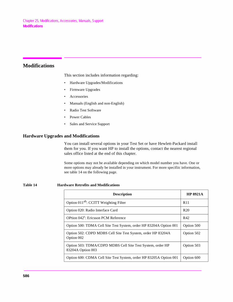
Chapter 25, Modifications, Accessories, Manuals, SupportModifications
ne or ion,
00
00
Modifications
This section includes information regarding:
• Hardware Upgrades/Modifications
• Firmware Upgrades
• Accessories
• Manuals (English and non-English)
• Radio Test Software
• Power Cables
• Sales and Service Support
Hardware Upgrades and Modifications
You can install several options in your Test Set or have Hewlett-Packard install them for you. If you want HP to install the options, contact the nearest regional sales office listed at the end of this chapter.
Some options may not be available depending on which model number you have. Omore options may already be installed in your instrument. For more specifiic informatsee table 14 on the following page.
Table 14 Hardware Retrofits and Modifications
Description HP 8921A
Option 011ab: CCITT Weighting Filter R11
Option 020: Radio Interface Card R20
OPtion 042c: Ericsson PCM Reference R42
Option 500: TDMA Cell Site Test System, order HP 83204A Option 001 Option 5
Option 502: CDPD MDBS Cell Site Test System, order HP 83204A Option 002
Option 502
Option 503: TDMA/CDPD MDBS Cell Site Test System, order HP 83204A Option 003
Option 503
Option 600: CDMA Cell Site Test System, order HP 83205A Option 001 Option 6
586
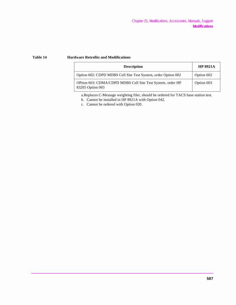
Chapter 25, Modifications, Accessories, Manuals, SupportModifications
a.Replaces C-Message weighting filer, should be ordered for TACS base station test.b. Cannot be installed in HP 8921A with Option 042.c. Cannot be ordered with Option 020.
Option 602: CDPD MDBS Cell Site Test System, order Option 002 Option 602
OPtion 603: CDMA/CDPD MDBS Cell Site Test System, order HP 83205 Option 003
Option 603
Table 14 Hardware Retrofits and Modifications
Description HP 8921A
587
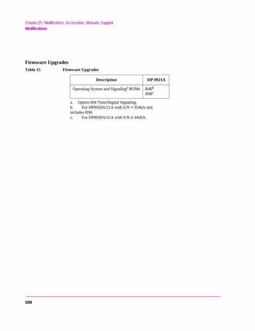
Chapter 25, Modifications, Accessories, Manuals, SupportModifications
Firmware Upgrades
a. Option 004 Tone/Digital Signaling. b. For HP8920A/21A with S/N < 3546A and includes R98.c. For HP8920A/21A with S/N ≥ 3456A.
Table 15 Firmware Upgrades
Description HP 8921A
Operating System and Signalinga ROMs R40b
R98c
588
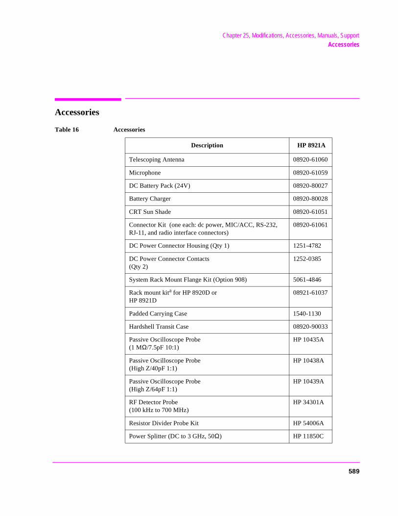
Chapter 25, Modifications, Accessories, Manuals, SupportAccessories
Accessories
Table 16 Accessories
Description HP 8921A
Telescoping Antenna 08920-61060
Microphone 08920-61059
DC Battery Pack (24V) 08920-80027
Battery Charger 08920-80028
CRT Sun Shade 08920-61051
Connector Kit (one each: dc power, MIC/ACC, RS-232, RJ-11, and radio interface connectors)
08920-61061
DC Power Connector Housing (Qty 1) 1251-4782
DC Power Connector Contacts (Qty 2)
1252-0385
System Rack Mount Flange Kit (Option 908) 5061-4846
Rack mount kita for HP 8920D or HP 8921D
08921-61037
Padded Carrying Case 1540-1130
Hardshell Transit Case 08920-90033
Passive Oscilloscope Probe (1 MΩ/7.5pF 10:1)
HP 10435A
Passive Oscilloscope Probe (High Z/40pF 1:1)
HP 10438A
Passive Oscilloscope Probe (High Z/64pF 1:1)
HP 10439A
RF Detector Probe (100 kHz to 700 MHz)
HP 34301A
Resistor Divider Probe Kit HP 54006A
Power Splitter (DC to 3 GHz, 50Ω) HP 11850C
589
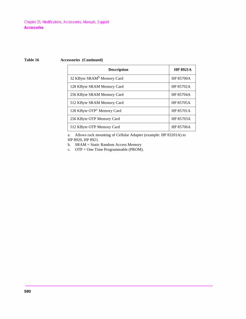
Chapter 25, Modifications, Accessories, Manuals, SupportAccessories
a. Allows rack mounting of Cellular Adapter (example: HP 83201A) to HP 8920, HP 8921. b. SRAM = Static Random Access Memory c. OTP = One Time Programmable (PROM).
32 KByte SRAMb Memory Card HP 85700A
128 KByte SRAM Memory Card HP 85702A
256 KByte SRAM Memory Card HP 85704A
512 KByte SRAM Memory Card HP 85705A
128 KByte OTPc Memory Card HP 85701A
256 KByte OTP Memory Card HP 85703A
512 KByte OTP Memory Card HP 85706A
Table 16 Accessories (Continued)
Description HP 8921A
590
Chapter 25, Modifications, Accessories, Manuals, SupportAccessories
r.
External Monitor
The CRT’s Video Output drives a multisync monitor at 19.2 kHz (analog). Examples of this type of monitor include the Electrohome ECM 1410-DMS 14-inch color monitor and the EVM 1242-P4VID 12-inch monochrome monito
591
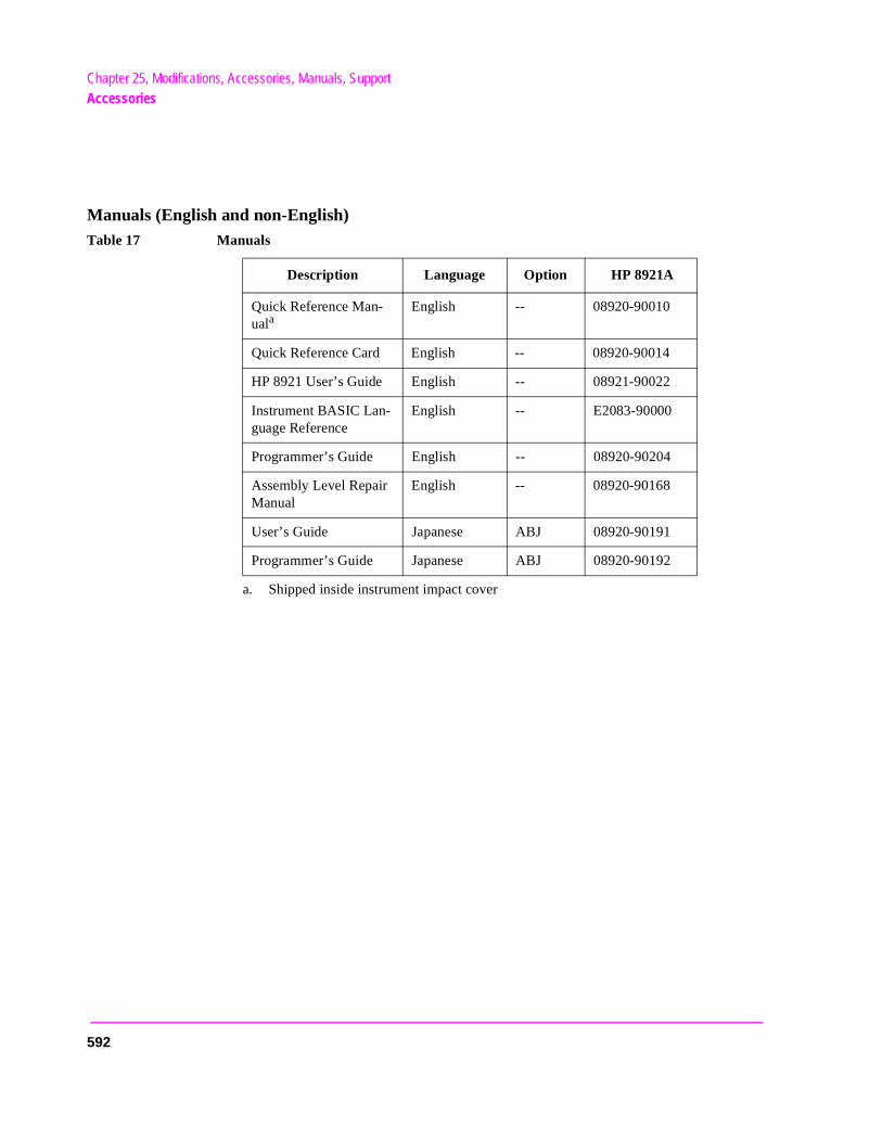
Chapter 25, Modifications, Accessories, Manuals, SupportAccessories
Manuals (English and non-English)
a. Shipped inside instrument impact cover
Table 17 Manuals
Description Language Option HP 8921A
Quick Reference Man-uala
English -- 08920-90010
Quick Reference Card English -- 08920-90014
HP 8921 User’s Guide English -- 08921-90022
Instrument BASIC Lan-guage Reference
English -- E2083-90000
Programmer’s Guide English -- 08920-90204
Assembly Level Repair Manual
English -- 08920-90168
User’s Guide Japanese ABJ 08920-90191
Programmer’s Guide Japanese ABJ 08920-90192
592
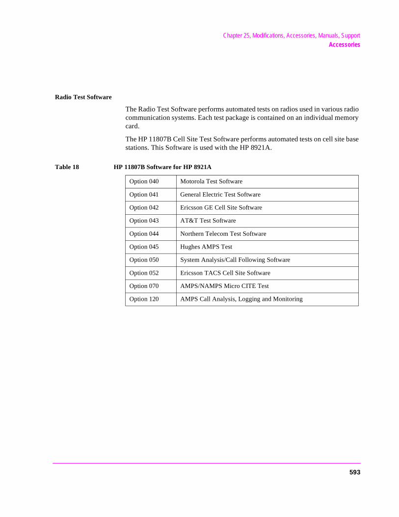
Chapter 25, Modifications, Accessories, Manuals, SupportAccessories
Radio Test Software
The Radio Test Software performs automated tests on radios used in various radio communication systems. Each test package is contained on an individual memory card.
The HP 11807B Cell Site Test Software performs automated tests on cell site base stations. This Software is used with the HP 8921A.
Table 18 HP 11807B Software for HP 8921A
Option 040 Motorola Test Software
Option 041 General Electric Test Software
Option 042 Ericsson GE Cell Site Software
Option 043 AT&T Test Software
Option 044 Northern Telecom Test Software
Option 045 Hughes AMPS Test
Option 050 System Analysis/Call Following Software
Option 052 Ericsson TACS Cell Site Software
Option 070 AMPS/NAMPS Micro CITE Test
Option 120 AMPS Call Analysis, Logging and Monitoring
593
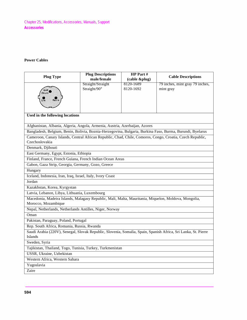
Chapter 25, Modifications, Accessories, Manuals, SupportAccessories
Power Cables
Plug Type Plug Descriptions
male/female HP Part #
(cable &plug) Cable Descriptions
Straight/Straight Straight/90°
8120-1689 8120-1692
79 inches, mint gray 79 inches, mint gray
Used in the following locations
Afghanistan, Albania, Algeria, Angola, Armenia, Austria, Azerbaijan, Azores
Bangladesh, Belgium, Benin, Bolivia, Boznia-Herzegovina, Bulgaria, Burkina Faso, Burma, Burundi, Byelarus
Cameroon, Canary Islands, Central African Republic, Chad, Chile, Comoros, Congo, Croatia, Czech Republic, Czechoslovakia
Denmark, Djibouti
East Germany, Egypt, Estonia, Ethiopia
Finland, France, French Guiana, French Indian Ocean Areas
Gabon, Gaza Strip, Georgia, Germany, Gozo, Greece
Hungary
Iceland, Indonesia, Iran, Iraq, Israel, Italy, Ivory Coast
Jordan
Kazakhstan, Korea, Kyrgystan
Latvia, Lebanon, Libya, Lithuania, Luxembourg
Macedonia, Madeira Islands, Malagasy Republic, Mali, Malta, Mauritania, Miquelon, Moldova, Mongolia, Morocco, Mozambique
Nepal, Netherlands, Netherlands Antilles, Niger, Norway
Oman
Pakistan, Paraguay, Poland, Portugal
Rep. South Africa, Romania, Russia, Rwanda
Saudi Arabia (220V), Senegal, Slovak Republic, Slovenia, Somalia, Spain, Spanish Africa, Sri Lanka, St. Pierre Islands
Sweden, Syria
Tajikistan, Thailand, Togo, Tunisia, Turkey, Turkmenistan
USSR, Ukraine, Uzbekistan
Western Africa, Western Sahara
Yugoslavia
Zaire
594
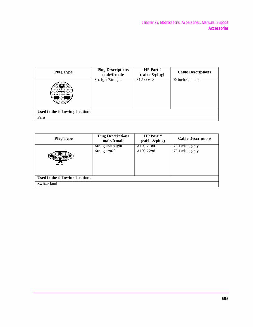
Chapter 25, Modifications, Accessories, Manuals, SupportAccessories
Plug Type Plug Descriptions
male/female HP Part #
(cable &plug) Cable Descriptions
Straight/Straight 8120-0698 90 inches, black
Used in the following locationsPeru
Plug Type Plug Descriptions
male/female HP Part #
(cable &plug) Cable Descriptions
Straight/Straight Straight/90°
8120-2104 8120-2296
79 inches, gray 79 inches, gray
Used in the following locationsSwitzerland
595
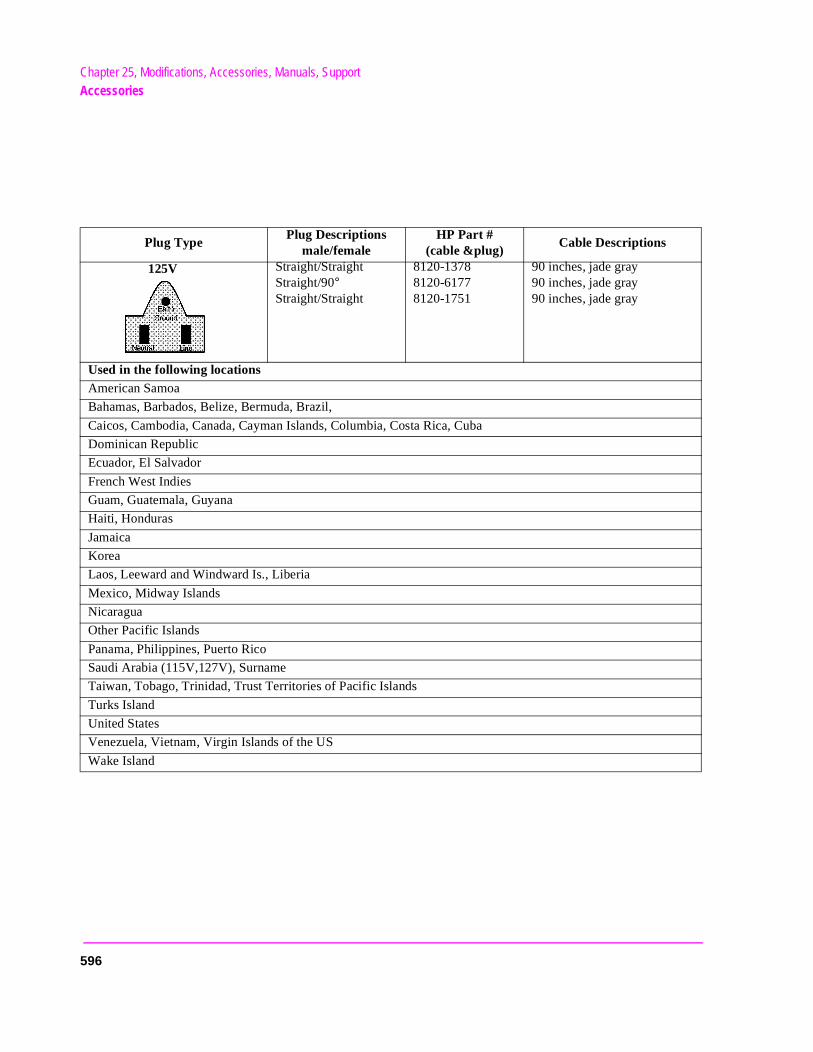
Chapter 25, Modifications, Accessories, Manuals, SupportAccessories
Plug Type Plug Descriptions
male/female HP Part #
(cable &plug) Cable Descriptions
Straight/Straight Straight/90° Straight/Straight
8120-1378 8120-61778120-1751
90 inches, jade gray 90 inches, jade gray 90 inches, jade gray
Used in the following locationsAmerican Samoa
Bahamas, Barbados, Belize, Bermuda, Brazil,
Caicos, Cambodia, Canada, Cayman Islands, Columbia, Costa Rica, Cuba
Dominican Republic
Ecuador, El Salvador
French West Indies
Guam, Guatemala, Guyana
Haiti, Honduras
Jamaica
Korea
Laos, Leeward and Windward Is., Liberia
Mexico, Midway Islands
Nicaragua
Other Pacific Islands
Panama, Philippines, Puerto Rico
Saudi Arabia (115V,127V), Surname
Taiwan, Tobago, Trinidad, Trust Territories of Pacific Islands
Turks Island
United States
Venezuela, Vietnam, Virgin Islands of the US
Wake Island
125V
596
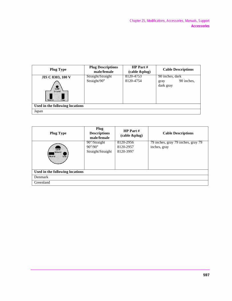
Chapter 25, Modifications, Accessories, Manuals, SupportAccessories
Plug Type Plug Descriptions
male/female HP Part #
(cable &plug) Cable Descriptions
Straight/Straight Straight/90°
8120-4753 8120-4754
90 inches, dark gray 90 inches, dark gray
Used in the following locationsJapan
Plug Type Plug
Descriptions male/female
HP Part # (cable &plug)
Cable Descriptions
90°/Straight 90°/90° Straight/Straight
8120-2956 8120-2957 8120-3997
79 inches, gray 79 inches, gray 79 inches, gray
Used in the following locationsDenmark
Greenland
JIS C 8303, 100 V
597
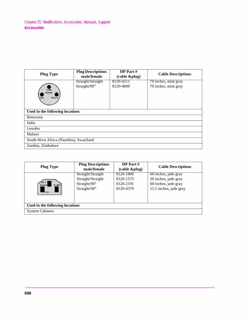
Chapter 25, Modifications, Accessories, Manuals, SupportAccessories
Plug Type Plug Descriptions
male/female HP Part #
(cable &plug) Cable Descriptions
Straight/Straight Straight/90°
8120-4211 8120-4600
79 inches, mint gray 79 inches, mint gray
Used in the following locationsBotswana
India
Lesotho
Malawi
South-West Africa (Namibia), Swaziland
Zambia, Zimbabwe
Plug Type Plug Descriptions
male/female HP Part #
(cable &plug) Cable Descriptions
Straight/Straight Straight/Straight Straight/90° Straight/90°
8120-1860 8120-1575 8120-2191 8120-4379
60 inches, jade gray 30 inches, jade gray 60 inches, jade gray 15.5 inches, jade gray
Used in the following locationsSystem Cabinets
598
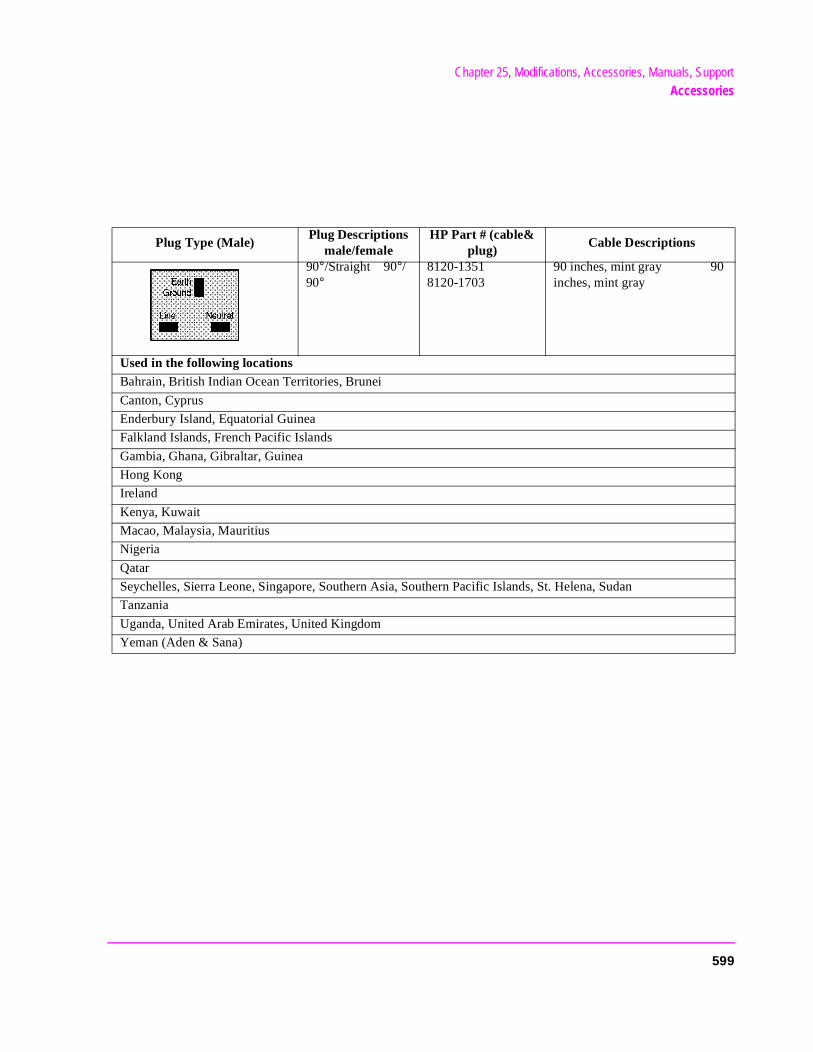
Chapter 25, Modifications, Accessories, Manuals, SupportAccessories
Plug Type (Male) Plug Descriptions
male/female HP Part # (cable&
plug) Cable Descriptions
90°/Straight 90°/90°
8120-1351 8120-1703
90 inches, mint gray 90 inches, mint gray
Used in the following locationsBahrain, British Indian Ocean Territories, Brunei
Canton, Cyprus
Enderbury Island, Equatorial Guinea
Falkland Islands, French Pacific Islands
Gambia, Ghana, Gibraltar, Guinea
Hong Kong
Ireland
Kenya, Kuwait
Macao, Malaysia, Mauritius
Nigeria
Qatar
Seychelles, Sierra Leone, Singapore, Southern Asia, Southern Pacific Islands, St. Helena, Sudan
Tanzania
Uganda, United Arab Emirates, United Kingdom
Yeman (Aden & Sana)
599
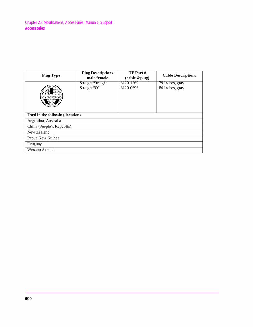
Chapter 25, Modifications, Accessories, Manuals, SupportAccessories
Plug Type Plug Descriptions
male/female HP Part #
(cable &plug) Cable Descriptions
Straight/Straight Straight/90°
8120-1369 8120-0696
79 inches, gray 80 inches, gray
Used in the following locationsArgentina, Australia
China (People’s Republic)
New Zealand
Papua New Guinea
Uruguay
Western Samoa
600
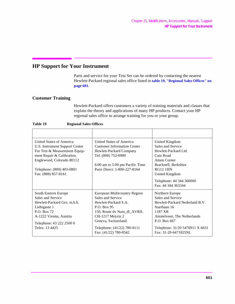
Chapter 25, Modifications, Accessories, Manuals, SupportHP Support for Your Instrument
HP Support for Your Instrument
Parts and service for your Test Set can be ordered by contacting the nearest Hewlett-Packard regional sales office listed in table 19, "Regional Sales Offices" on page 601.
Customer Training
Hewlett-Packard offers customers a variety of training materials and classes that explain the theory and applications of many HP products. Contact your HP regional sales office to arrange training for you or your group.
Table 19 Regional Sales Offices
United States of AmericaU.S. Instrument Support CenterFor Test & Measurement Equip-ment Repair & Calibration.Englewood, Colorado 80112
Telephone: (800) 403-0801Fax: (888) 857-8161
United States of AmericaCustomer Information CenterHewlett-Packard CompanyTel: (800) 752-0900
6:00 am to 5:00 pm Pacific TimeParts Direct: 1-800-227-8164
United KingdomSales and ServiceHewlett-Packard Ltd.Cain RoadAmen CornerBracknell, BerkshireRG12 1HNUnited Kingdom
Telephone: 44 344 360000Fax: 44 344 363344
South Eastern EuropeSales and ServiceHewlett-Packard Ges. m.b.h.Liebigasse 1P.O. Box 72A-1222 Vienna, Austria
Telephone: 43 222 2500 0Telex: 13 4425
European Multicountry RegionSales and ServiceHewlett-Packard S.A.P.O. Box 95150, Route dv Nant_dl_AVRILCH-1217 Meyrin 2Geneva, Switzerland
Telephone: (41/22) 780-8111Fax: (41/22) 780-8542
Northern EuropeSales and ServiceHewlett-Packard Nederland B.V.Startbaan 161187 XRAmstelveen, The NetherlandsP.O. Box 667
Telephone: 31/20 5476911 X 6631Fax: 31-20-6471825NL
601
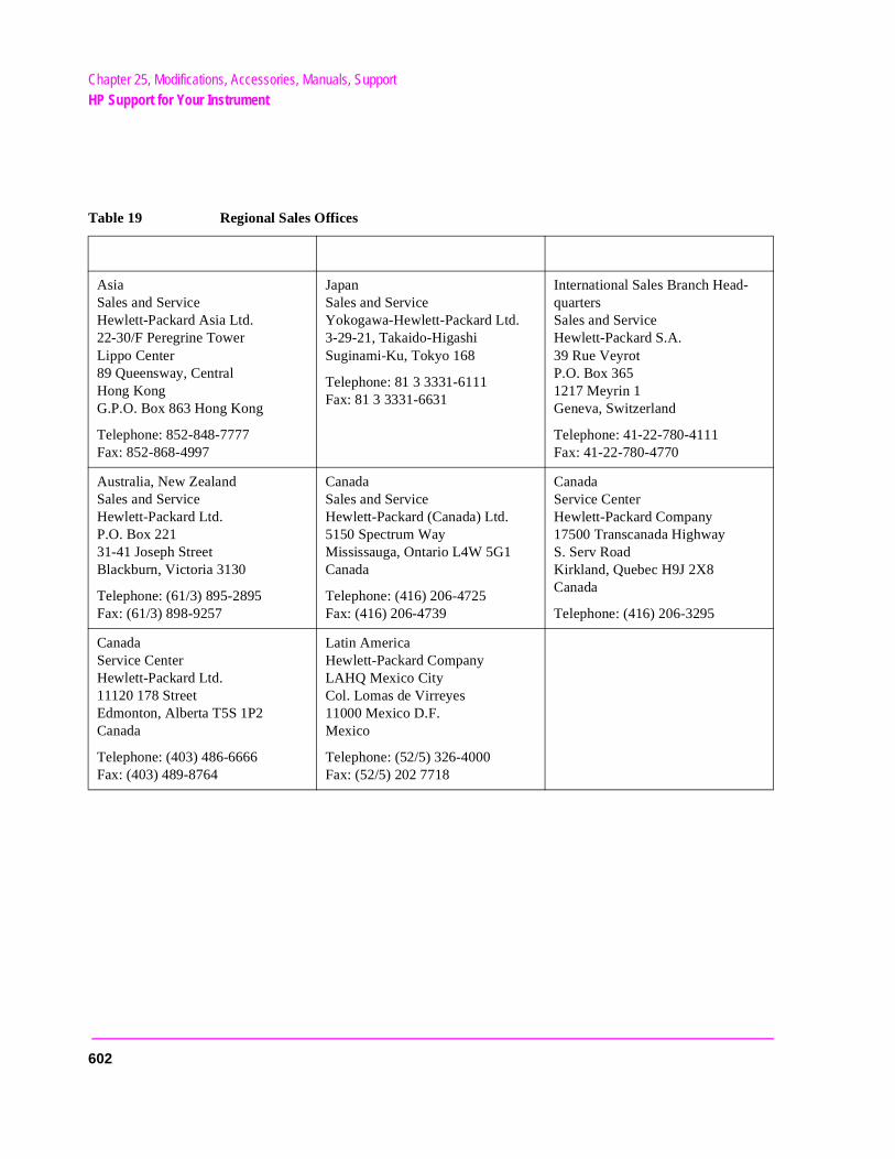
Chapter 25, Modifications, Accessories, Manuals, SupportHP Support for Your Instrument
AsiaSales and ServiceHewlett-Packard Asia Ltd.22-30/F Peregrine TowerLippo Center89 Queensway, CentralHong KongG.P.O. Box 863 Hong Kong
Telephone: 852-848-7777Fax: 852-868-4997
JapanSales and ServiceYokogawa-Hewlett-Packard Ltd.3-29-21, Takaido-HigashiSuginami-Ku, Tokyo 168
Telephone: 81 3 3331-6111Fax: 81 3 3331-6631
International Sales Branch Head-quartersSales and ServiceHewlett-Packard S.A.39 Rue VeyrotP.O. Box 3651217 Meyrin 1Geneva, Switzerland
Telephone: 41-22-780-4111Fax: 41-22-780-4770
Australia, New ZealandSales and ServiceHewlett-Packard Ltd.P.O. Box 22131-41 Joseph StreetBlackburn, Victoria 3130
Telephone: (61/3) 895-2895Fax: (61/3) 898-9257
CanadaSales and ServiceHewlett-Packard (Canada) Ltd.5150 Spectrum WayMississauga, Ontario L4W 5G1Canada
Telephone: (416) 206-4725Fax: (416) 206-4739
CanadaService CenterHewlett-Packard Company17500 Transcanada HighwayS. Serv RoadKirkland, Quebec H9J 2X8Canada
Telephone: (416) 206-3295
CanadaService CenterHewlett-Packard Ltd.11120 178 StreetEdmonton, Alberta T5S 1P2Canada
Telephone: (403) 486-6666Fax: (403) 489-8764
Latin AmericaHewlett-Packard CompanyLAHQ Mexico CityCol. Lomas de Virreyes11000 Mexico D.F.Mexico
Telephone: (52/5) 326-4000Fax: (52/5) 202 7718
Table 19 Regional Sales Offices
602

Error Messages
549
Error Messages
you t.
General Information About Error Messages
Information concerning error messages displayed by the Test Set may be found in one of the following manuals:
• HP 8920A, HP 8920B, or HP 8921A User’s Guides
• HP 8920A, HP 8920B, or HP 8921A Programmer’s Guide
• HP 8920A, HP 8920B, or HP 8921 Assembly Level Repair Manual
• HP Instrument BASIC User’s Handbook:
• HP 8920A or HP 8921A: HP Instrument BASIC Users Handbook (HP P/N E2083-90000)
• HP 8920B: HP Instrument BASIC Users Handbook Version 2.0 (HP P/N E2083-90005)
The format of the displayed message determines which manual contains informationabout the error message. There are four basic error message formats:
• Positive numbered error messages • IBASIC error messages • HP-IB error messages • Text only error messages
The following paragraphs give a brief description of each message format and directto the manual to look in for information about error messages displayed in that forma
550
Error Messages
Positive Numbered Error Messages
Positive numbered error messages are generally associated with IBASIC. Refer to the HP Instrument BASIC User’s Handbook for information on IBASIC error messages.
Positive numbered error messages take the form: ERROR XX
For example:
• Error 54 Duplicate file name
• or
• Error 80 in 632 Medium changed or not in drive
551
Error Messages
Negative Numbered Error Messages
Negative numbers preceding the error messages text correspond to the error conditions outlined in the Standard Commands for Programmable Instruments (SCPI). For more information on SCPI, order the following book,
A Beginner’s Guide to SCPI Addison-Wesley Publishing Company ISBN 0-201-56350-9 HP P/N 5010-7166
or contact,
Fred Bode, Executive Director SCPI Consortium 8380 Hercules Drive, Suite P3La Mesa, CA 91942 Phone: (619) 697-8790, FAX: (619) 697-5955 CompuServe Number: 76516,254
Negative numbered error messages take the form: ERROR −XX <error message>
For example:
Error -128 Numeric data not allowed
or
Error -141 Invalid character data
552
Error Messages
IBASIC Error Messages
IBASIC Error Messages are associated with IBASIC operation. IBASIC error messages can have both positive and negative numbers. Refer to the HP Instrument BASIC User’s Handbook for information on positive numbered error messages. Refer to the HP-IB Error Messages section of the Programmer’s Guide for information on negative numbered error messages (the error message associated with a negative number is the same for HP-IB errors and IBASIC errors).
IBASIC error messages take the form: IBASIC Error: -XX
For example:
• IBASIC Error: -286 Program runtime error
553
Error Messages
HP-IB Error Messages
HP-IB Error Messages are associated with HP-IB operation. Refer to the Programmers Guide for information on HP-IB error messages.
HP-IB error messages take the form: HP-IB Error: -XX or HP-IB Error
For example:
HP-IB Error: -410 Query INTERRUPTED.
or
HP-IB Error: Input value out of range.
554
Error Messages
in
Text Only Error Messages
Text only error messages are generally associated with manual operation of the Test Set. This manual contains information on text only error messages.
Text only error messages can also be displayed while running the Test Set’s built-in diagnostic or calibration utility programs. Refer to the Assembly Level Repair manual for information on text only error messages displayed while running the Test Set’s built-diagnostic or calibration utility programs.
Text only error messages take the form: This is an error message.
For example:
• Input value out of range.
555

Error Messages
y. eneral e ists, only knob ed on
(turn nd
The Message Display
During instrument operation, various messages may appear on the Test Set’s displaPrompt-type messages generally appear on the first line of the Test Set’s display. Goperating and error messages usually appear on the second line of the display. Sommessages are persistent; they remain displayed until the error condition no longer exor until another persistent message with greater priority occurs. Other messages aredisplayed when the error first occurs; they are removed when a key is pressed or theis turned, or when an HP-IB command is received. Many of the messages are displaythe MESSAGE screen until the instrument is turned off.
Messages that are about error conditions may tell you what to do to correct the errorsomething off, reduce a field’s value, press a certain key, and so forth). Messages aprompts are sometimes accompanied by a beep or warble.
NOTE: Warbles and Beeps
A warble sound indicates that an instrument-damaging event is occurring. Beepsoften occur only with the first occurrence of the message. Prompts are generallysilent.
556

Error Messages
e ) has
Non-Recoverable Firmware Error
The non-recoverable firmware error is very important. It appears when an unanticipated event occurs that the Test Set’s firmware cannot handle. The message appears in thcenter of the Test Set’s display and (except for the two lines in the second paragraphthe form:
Non-recoverable firmware error. Please record the 2 lines oftext below and contact Hewlett-Packard through your localservice center or by calling (800) 827-3848 (USA, collect) andasking to speak to the Service Engineer.
‘Address error exception’ at line number 0
To continue operation, turn POWER off and back on.
Follow the instructions in the message.
Unfortunately, you will not be able to recover from this condition. You must switch the Test Set off and back on. When you rerun the test where the Error Message occurred, it may not occur again. If it does reappear, it would be helpful to Hewlett-Packard to record exactly what the configuration of the instrument was when the error appeared and contact Hewlett-Packard.
557

Error Messages
turn
,
g the
le, A
Text Only Error Messages
Operation errors generally occur when you try to do something the Test Set was not designed to do. Most messages tell you what to do to correct the problem, (turn something off, reduce a field’s value, press a certain key,…and so forth).
Some common messages are listed here:
All self tests passed.
The Test Set did not detect any hardware or firmware failures during its initial self-diagnostics. This message should always be displayed immediately after instrumenton.
Input value out of range.
A number was entered that was too large or small for the selected field, for exampletrying to set AFG1 Freq to 125 kHz.
Invalid keystroke.
You used a key that has no function relating to the selected field, for example, pressin[ON/OFF] key while the Filter 1 field is selected.
Option not installed.
You selected a function that requires optional hardware that is not present for exampselecting TDMA TEST from the To Screen menu when you do not have an HP 83201or HP 83201B Cellular Adapter connected to the Test Set.
558
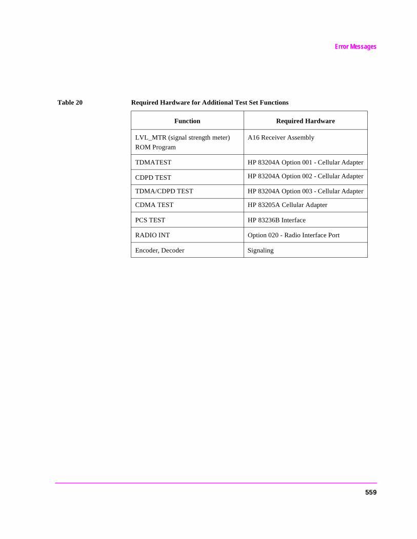
Error Messages
Table 20 Required Hardware for Additional Test Set Functions
Function Required Hardware
LVL_MTR (signal strength meter)
ROM Program
A16 Receiver Assembly
TDMATEST HP 83204A Option 001 - Cellular Adapter
CDPD TEST HP 83204A Option 002 - Cellular Adapter
TDMA/CDPD TEST HP 83204A Option 003 - Cellular Adapter
CDMA TEST HP 83205A Cellular Adapter
PCS TEST HP 83236B Interface
RADIO INT Option 020 - Radio Interface Port
Encoder, Decoder Signaling
559

Error Messages
e Test
t gate sent
Turn off either AM or FM settings.
You tried to create simultaneous AM and FM (using any combination of AFGen1, AFGen2, and the Mod In To field). The Test Set does not provide simultaneous AM and FM.
Squelch interrupt overflow. Press MEAS RESET.
The Test Set temporarily interrupts audio measurements when squelch is first broken to prevent internal switching transients from influencing measurements (except when using the OSCILLOSCOPE, SPECTRUM ANALYZER, DECODER, or SERVICE screens). If squelch is repetitively broken in a period of a few seconds, the duration of measurement interruption becomes too great, and the Test Set stops interrupting the signal. Following measurements may be influenced by transient signals.
Pressing [MEAS RESET] clears the data buffer used to generate interrupts, resetting the normal squelch operation to eliminate transients.
This condition may occur when monitoring low-level off-the-air signals.
Cal file checksum incorrect - initializing file.
This error usually occurs after changing the Test Set’s firmware ROM’s. It is not a problem in that instance, but should not re-appear during subsequent operation of thSet.
Decoder buffer full. Decrease gate time.
Too many decoder samples were sent to the decoder’s buffer during a measurementime causing a data overflow. Reducing the gate time decreases the amount of dataduring each measurement.
560
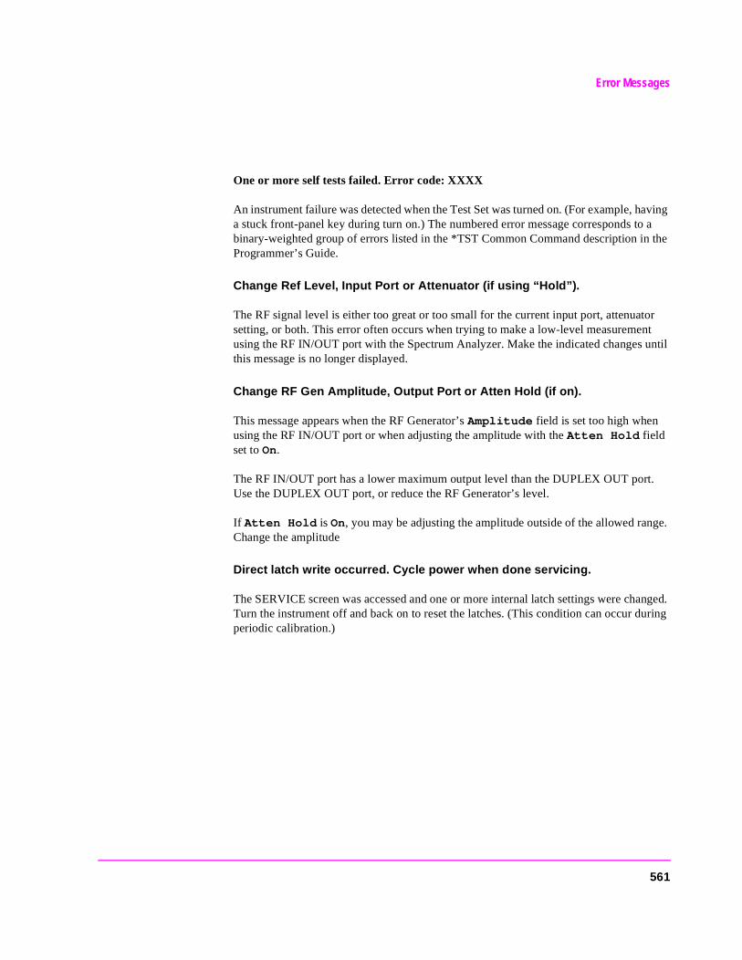
Error Messages
.
ge.
anged. uring
One or more self tests failed. Error code: XXXX
An instrument failure was detected when the Test Set was turned on. (For example, having a stuck front-panel key during turn on.) The numbered error message corresponds to a binary-weighted group of errors listed in the *TST Common Command description in the Programmer’s Guide.
Change Ref Level, Input Port or Attenuator (if using “Hold”).
The RF signal level is either too great or too small for the current input port, attenuator setting, or both. This error often occurs when trying to make a low-level measurement using the RF IN/OUT port with the Spectrum Analyzer. Make the indicated changes until this message is no longer displayed.
Change RF Gen Amplitude, Output Port or Atten Hold (if on).
This message appears when the RF Generator’s Amplitude field is set too high when using the RF IN/OUT port or when adjusting the amplitude with the Atten Hold field set to On.
The RF IN/OUT port has a lower maximum output level than the DUPLEX OUT portUse the DUPLEX OUT port, or reduce the RF Generator’s level.
If Atten Hold is On, you may be adjusting the amplitude outside of the allowed ranChange the amplitude
Direct latch write occurred. Cycle power when done servicing.
The SERVICE screen was accessed and one or more internal latch settings were chTurn the instrument off and back on to reset the latches. (This condition can occur dperiodic calibration.)
561

Error Messages
562
Index
- - - -meaning of, ACP level measurement,
87meaning of, AF frequency, 119meaning of, FM deviation, 123meaning of, squelch, 423meaning of, TX frequency error, 128meaning of, TX power measurement,
58, 87, 93, 108, 298, 426, 437, 505
Symbols(Gen)-(Anl)
Configure screen, 206
Numerics10 MHz REF INPUT connector
description, 52510 MHz REF OUTPUT connector
description, 525114.3 MHz IF OUT connector
description, 51224-hour clock
setting, 214600 ohm impedance
at AUDIO IN, 99
563
Index
Aabbreviated address word
forward control channel, 179reverse control channel, 144
Abort PrintPrint Configure screen, 400
abort printing, 66ac
power source, 529ac coupling
input, 294, 306, 316, 321, 325, 330,340, 343, 372, 379, 434
output, 292, 302, 315, 320, 325, 329,340, 343, 370, 378, 434
AC LevelAF Analyzer screen, 97Duplex Test screen, 287Radio Frequency Analyzer screen, 419RF Analyzer screen, 419RF Generator screen, 431RX Test screen, 442
ac levelmeasurement, 59peak detector, 104
AC, access channel, 271AC/DC button, 529Access annunciator
Call Bit screen, 163Call Control screen, 119Call Data screen, 141
access channelchannel number, call processing, 199channel number, NMT, 371
Access Channel NumberSignaling Encoder screen, NMT mode,
367Access Channel Power
Signaling Encoder screen, NMT mode,367
access message, 171accessing screens, 42accessories, 535ACP, 87
AM transmitter, 86input port, 87level, 87measurement, 86measurement speed, 92
output port, 86ratio, 87
ACP MeasAdjacent Channel Power screen, 87
ActiveCall Bit screen, 163Call Control screen, 119Call Data screen, 141
Active annunciatorCall Bit screen, 164Call Control screen, 119Call Data screen, 141
Add InfoSignaling Encoder screen, NMT mode,
367add options, 532Addr
Tests (External Devices) screen, 485address
digital paging, 322HP-IB, external devices, 485HP-IB, printer, 401, 489HP-IB, test set, 385, 528key, 528pager, 232
Address QualifierSignaling Encoder screen, MPT 1327
mode, 350adjacent channel power
measurement, 87Adjacent Channel Power screen
ACP Meas, 87AFGen1 Freq, 88AFGen1 To, 88Carrier Ref, 88Ch Offset, 90Channel BW, 88Ext TX Key, 90Input Atten, 90Input Port, 91Res BW, 92Tune Freq, 92Tune Mode, 92TX Freq Error, 93TX Frequency, 93TX Power, 93TX Pwr Zero, 94view of, 87
ADRS key, 528advanced mobile phone service
decoder, 217encoder, 301
AF analyzerCDCSS decoder settings, 230input, 97, 218, 226, 231, 235, 241, 247,
251, 263, 281, 288, 498level, 219, 228, 233, 237, 242, 248,
252, 265, 282signal types analyzed, 97, 288, 498
AF Analyzer screenAC Level, 97AF Anl In, 97AF Cnt Gate, 98AF Freq, 106Audio In Lo, 99Current, 99, 106DC current, 99DC Level, 100, 106De-Emp Gain, 100De-emphasis, 100Detector, 101Distn, 106Ext Load R, 102Filter 1 and Filter 2, 102FM Deviation, 102functional block diagram, 97Gain Cntl, 103Input Gain, 103Notch Freq, 104Notch Gain, 104Pk Det To, 104Scope To, 105Settling, 105SINAD, 106SNR, 106Speaker ALC, 107Speaker Vol, 107TX Freq Error, 107TX Frequency, 107TX Power, 108view of, 97
AF Anl InAF Analyzer screen, 97Analog Meas screen, 192Duplex Test screen, 288Signaling Decoder screen, AMPS-
564
Index
TACS mode, 218Signaling Decoder screen, CDCSS
mode, 226Signaling Decoder screen, Digi Page
mode, 231Signaling Decoder screen, DTMF
mode, 235Signaling Decoder screen, EDACS
mode, 241Signaling Decoder screen, Func Gen
mode, 247Signaling Decoder screen, LTR mode,
251Signaling Decoder screen, NAMPS-
NTACS mode, 218Signaling Decoder screen, NMT mode,
263Signaling Decoder screen, Tone Seq
mode, 281TX Test screen, 498
AF Cnt GateAF Analyzer screen, 98
AF FreqAF Analyzer screen, 106Analog Meas screen, 193Call Control screen, 119Duplex Test screen, 289RF Generator screen, 436RX Test screen, 446TX Test screen, 98, 499
AF frequencymodulation quality, 121
AF generator 1amplitude, 290, 432, 443frequency, 88, 290, 432, 442, 500level, 500modulation, 88, 290, 432, 443
AF generator 2amplitude, 302, 315, 320, 325, 329,
340, 343, 368, 378, 433, 443frequency, 340, 432, 442modulation, 302, 315, 320, 325, 329,
340, 343, 368, 378, 433, 443use of, 300
AF powerexternal load resistance, 60, 97, 431,
442measurement, 60
AFGen1 FreqAdjacent Channel Power screen, 88Analog Meas screen, 193Duplex Test screen, 290RF Generator screen, 432RX Test screen, 442TX Test screen, 500
AFGen1 LvlTX Test screen, 500
AFGen1 ToAdjacent Channel Power screen, 88Analog Meas screen, 193Duplex Test screen, 290RF Generator screen, 432RX Test screen, 443
AFGen2 FreqRF Generator screen, 432RX Test screen, 442Signaling Encoder screen, Func Gen
mode, 340AFGen2 To
RF Generator screen, 433RX Test screen, 443Signaling Encoder screen, AMPS-
TACS mode, 302, 305Signaling Encoder screen, CDCSS
mode, 315Signaling Encoder screen, Digi Page
mode, 320Signaling Encoder screen, DTMF
mode, 325Signaling Encoder screen, EDACS
mode, 329Signaling Encoder screen, Func Gen
mode, 340Signaling Encoder screen, LTR mode,
343Signaling Encoder screen, NAMP-
NTAC mode, 302, 305Signaling Encoder screen, NMT mode,
368Signaling Encoder screen, Tone Seq
mode, 378Alarm Level High
Signaling Encoder screen, NMT mode,369
Alarm Level LowSignaling Encoder screen, NMT mode,
369ALC
disabling, 107internal speaker, 107
alert order, 138All Chans?
Tests (Order of Tests) screen, 474Aloha Number
Signaling Encoder screen, MPT 1327mode, 351
alpha-numeric operationdigital paging, 321
alternate traffic area, 375alternate traffic channel
number, 376power, 376
AMdepth, 59input, 435RF generator, 88, 290, 302, 315, 320,
325, 329, 340, 343, 368, 378, 432,433, 443
AM DepthAudio Analyzer Screen, 99, 419
amplifierfor distortion measurements, 104for SINAD measurements, 104
AmplitudeAnalog Meas screen, 193Call Control screen, 119Duplex Test screen, 291RF Generator screen, 433RX Test screen, 444Spectrum Analyzer screen, 455
amplitudeAFGen1, 88, 290, 432, 443AFGen2, 302, 315, 320, 325, 329, 340,
343, 368, 378, 433, 443for call control, 119for tone sequence, 380function generator, 340off, 88, 290, 302, 315, 320, 325, 329,
340, 343, 368, 378, 432, 433, 443RF generator, 291, 433, 444, 455tracking generator, 457twist, 327vertical sensitivity, 393
AMPS Call Control screen
565
Index
view of, 118AMPS-TACS
control channel decoder, 217forward control channel, 301forward voice channel, 301radio standard, 312reverse control channel, 222reverse voice channel, 222simulated system, 128voice channel decoder, 217
AMPS-TACS decoder modeAF Anl In, 218Arm Meas, 218Channel, 218Data (hex), 219Gate Time, 219Input Level, 219Num of Bits, 220Polarity, 220Single/Cont, 221Stop Meas, 221Trig Level, 221Trigger Pattern (bin), 221view of, 217
AMPS-TACS encoder modeAFGen2 To, 302Audio Out, 302B/I Delay, 303Bursts, 303Busy/Idle, 303Channel, 303Data Level, 303Data Rate, 304Filler, 305FM Coupling, 306Message, 307, 308Polarity, 310SAT Freq, 311SAT Level, 311Send, 311Send Filler, 311Send Mode, 312Standard, 312Stop, 312Stop Filler, 312view of, 301
Analog Meas screenAF Anl In, 192
AF Freq, 193AFGen1 Freq, 193AFGen1 To, 193Amplitude, 193De-Emphasis, 193Detector, 194Filter 1, 194Filter 2, 194FM Deviation, 194TX Freq Error, 194TX Power, 194view of, 192
analog meter, 62analyzer
arming measurements, 221, 229, 234,238, 243, 249, 254, 266, 283
calibration, 464disarming measurements, 243frequency, markers, 460input port, 454level, markers, 460
analyzer, AFCDCSS decoder settings, 230input, 218, 226, 231, 235, 241, 247,
251, 263, 281level, 219, 228, 233, 237, 242, 248,
252, 265, 282analyzer, RF
frequency, 297, 425, 504input attenuation, 421input port, 422level, 419measurements, 424sensitivity, 423tuning, 297, 425, 504
ANT IN connectoravoiding damage, 58, 91, 108, 295,
298, 422, 426, 454, 503, 505, 508connecting to, 40, 454description, 508for ACP ratio measurements, 87, 91for off-the-air measurements, 91, 256,
295, 422, 503for RF measurements, 91, 295, 422,
503gain at, 202input attenuation, 90, 421, 461loss at, 202
sensitivity, 423, 463Antenna In
Configure screen, 202Area #
Signaling Encoder screen, NMT mode,369
Area 1Signaling Encoder screen, LTR mode,
343Area 2
Signaling Encoder screen, LTR mode,343
armmeasurment, 218, 221, 227, 229, 231,
234, 235, 238, 242, 243, 248, 249,251, 254, 266, 281, 283
radio interface interrupt, 407Arm Meas
Signaling Decoder screen, AMPS-TACS mode, 218
Signaling Decoder screen, CDCSSmode, 227
Signaling Decoder screen, Digi Pagemode, 231
Signaling Decoder screen, DTMFmode, 235
Signaling Decoder screen, EDACSmode, 242
Signaling Decoder screen, Func Genmode, 248
Signaling Decoder screen, LTR mode,251
Signaling Decoder screen, NAMPS-NTACS mode, 218
Signaling Decoder screen, Tone Seqmode, 281
arrow down key, 527arrow left key, 529arrow up key, 527ASCII terminal, 81
configuring, 388ASSIGN, 77, 78Atten Hold
Duplex Test screen, 291RF Generator screen, 434RX Test screen, 444
attenuationautomatic control, 90, 421, 461
566
Index
input, RF analyzer, 90, 421input, spectrum analyzer, 461manual control, 90, 421, 461
attenuatordecoder interference, 103, 421input, 90, 421, 461oscilloscope interference, 103, 421
attenuator hold, 291, 434, 444Audio Analyzer Screen
AM Depth, 99, 419Audio Frequency Analyzer screen
Distortion, 100audio frequency counter
gate time, 98sampling, 98
audio frequency generator, 442audio frequency measurements, 59, 98,
106, 289, 424, 436, 446, 499AUDIO IN connector
avoiding damage to, 509description, 509for ac level measurement, 97, 431, 442for ac level measurements, 59for call processing, 116for external load resistancemeasure-
ment, 102, 444for SNR operation, 98, 106, 289, 436,
446, 499AUDIO IN HI connector, 509Audio In Lo
AF Analyzer screen, 99AUDIO IN LO connector
600 ohm impedance, 99, 509floating, 99, 509grounded, 99, 509
AUDIO MONITOR OUTPUT connectordescription, 510
Audio OutDuplex Test screen, 292RF Generator screen, 434Signaling Encoder screen, AMPS-
TACS mode, 302Signaling Encoder screen, CDCSS
mode, 315Signaling Encoder screen, Digi Page
mode, 320Signaling Encoder screen, DTMF
mode, 325
Signaling Encoder screen, EDACSmode, 329
Signaling Encoder screen, Func Genmode, 340
Signaling Encoder screen, LTR mode,343
Signaling Encoder screen, NAMP-NTAC mode, 302
Signaling Encoder screen, NMT mode,370
Signaling Encoder screen, Tone Seqmode, 378
AUDIO OUT connectorcoupling, 292, 302, 315, 320, 325, 329,
340, 343, 370, 378, 434description, 510
audio powermeasurement, 97, 431, 442
audio source, 218, 226, 231, 235, 241,247, 251, 263, 281
Auto AllRange Hold, 208
Auto/NormOscilloscope screen, 396
automatic level control, 107autoranging
AF/RF measurements, 208gain setting, 103input attenuator, 103, 421
Autostart Test Procedure on Power-UpTests (ExecutionConditions) screen,
482auto-tuning
AF/RF measurements, 208RF, 92, 297, 425, 504
averagingexample, 69measurement results, 69restart averaging, 69
AVG, 69, 527
BB/I Delay (FOCC)
Signaling Encoder screen, AMPS-TACS mode, 303
Signaling Encoder screen, NAMP-NTAC mode, 303
backspace key, 529bandwidth
adjacent channel power, 88IF filter, 295, 421, 502resolution, ACP measurement, 92
Base FreqConfigure screen, 203
base settingschanging, 74default, 74
base station receiversimulating, AMPS-TACS/NAMPS-
NTACS, 217basic operation, 53Batt Save
Signaling Encoder screen, NMT mode,370
battery, 51saving, 370
baud rate, 387beat frequency, 62Beeper
Configure screen, 51, 204beeper
error alert, 204volume control, 51, 204
Bellradio standard, 326
biasdc, offsetting, 434
billing information, 375bit error, 320bits
CDCSS data rate, 227CDCSS data stream, 318CDCSS sequence, 227digitial paging data rate, 232dotting, 306, 308information, 306, 308LTR data rate, 252message, 225NMT data rate, 371
567
Index
parity, 225, 306, 308, 309serial data word, 385specifying patter to display, 221sync word, 225triggering, 221type, 306, 308word sync, 306, 308
block diagramAF Analyzer, 97Duplex Test screen, 287RF Analyzer, 419RF Generator, 431RX Test, 441TX Test, 497
brightnesssetting, 50, 207
BSdefinition, 262
BS IdentitySignaling Encoder screen, NMT mode,
370buffer overflow error, 233Bursts
Signaling Encoder screen, AMPS-TACS mode, 303
Signaling Encoder screen, CDCSSmode, 315
Signaling Encoder screen, Digi Pagemode, 320
Signaling Encoder screen, DTMFmode, 325
Signaling Encoder screen, LTR mode,343
Signaling Encoder screen, NAMP-NTAC mode, 303
Signaling Encoder screen, Tone Seqmode, 379
busy state, 303Busy/Idle
Signaling Encoder screen, AMPS-TACS mode, 303
Signaling Encoder screen, NAMP-NTAC mode, 303
Ccables
power, 539calibration
spectrum analyzer, 464Call Bit screen
Access annunciator, 163Active, 163Active annunciator, 164Connect annunciator, 164Data Spec, 164Set Message, 166view of, 161
Call Configure screenCMAX, 199Detector, 199TX Pwr Zero, 199view of, 198
Call Control screenAccess annunciator, 119Active, 119Active annunciator, 119AF Freq, 119Amplitude, 119Called Number, 120Chan, 120Cntl Channel, 120Connect annunciator, 120Display, 121ESN (dec), 123ESN (hex), 123FM Deviation, 123Handoff, 123, 142, 165MS Id, 124Order, 125Page, 125Page annunciator, 126Phone Num, 126Pwr Lvl, 125Register, 126Register annunciator, 126Release, 126SAT, 127SCM, 127SID, 127System Type, 128TX Freq Error, 128TX Power, 128
view of, decoding error message, 122Call Data screen
Access annunciator, 141Active, 141Active annunciator, 141Connect annunciator, 141Display Word, 142Order, 142, 165Page, 142, 166Page annunciator, 142, 166Register, 143, 166Register annunciator, 143, 166Release, 143, 166view of, 139
call origination, 137call processing
AUDIO IN connector, 116connecting mobile station, 114description, 109general procedure, 117operational overview, 111screen, description of, 113state diagram, 112
Called NumberCall Control screen, 120
Calling Channel NumberSignaling Encoder screen, NMT mode,
371Calling Name
Tests (External Devices) screen, 485CALLP
RECCW A, 140RECCW B, 140RECCW C, 140RECCW D, 140RECCW E, 140RVCOrdCon, 140
CANCEL key, 529card
procedure location, 470, 480Carrier
Configure screen, 213carrier
effect on RX/TX screen, 213Carrier Ref
Adjacent Channel Power screen, 88CC, calling channel, 271CCIR1
568
Index
radio standard, 379CCIR2
radio standard, 379CCITT
radio standard, 379CDCSS decoder mode
AF analyzer settings, 230AF Anl In, 226Arm Meas, 227Code (oct), 227Data (bin), 227Data Rate, 227Input Level, 228Polarity, 228Single/Cont, 229Stop Meas, 229Trig Level, 229view of, 226
CDCSS encoder modeAFGen2 To, 315Audio Out, 315Bursts, 315Code, 315Data Rate, 315FM Coupling, 316Polarity, 316Send, 316Send Mode, 317Standard, 317Stop, 317TOC Time, 317view of, 314
cellular adapterconnectors, 512
cellular telephone, 313Center Freq
Spectrum Analyzer screen, 453center frequency
for notch filter, 104for spectrum analyzer, 453RF signal, 92, 297, 425, 504spectrum analyzer marker, 459
Ch OffsetAdjacent Channel Power screen, 90
ChanCall Control screen, 120
Chan SpaceConfigure screen, 204
ChannelSignaling Decoder screen, AMPS-
TACS mode, 218Signaling Decoder screen, NAMPS-
NTACS mode, 218Signaling Encoder screen, AMPS-
TACS mode, 303Signaling Encoder screen, NAMP-
NTAC mode, 303channel
access, NMT, 371assignments, NMT, 371bandwidth, ACP measurement, 88calling, NMT, 371changing, 349number, control channel, 120number, NMT encoder, 371offset, ACP measurement, 90spacing, user defined, 204traffic, NMT, 371trunked home, receiver, 347trunked home, transmitter, 348tuning, 210
Channel BWAdjacent Channel Power screen, 88
channel powerlevel, 87measurement, 86measuring, 87ratio, 87
channel standardAMPS (MS, LS), 209ETACS (MS, LS), 209JTACS (MS, LS), 209LTR800/900 (MS, LS), 209NAMPS(MSL, MSM, MSU, LSL,
LSM, LSU), 209NTACS (MS, LS), 209TACS (MS, LS), 209USER-DEF, 209
chassis ground, 511Check
Tests (Pass/Fail Limits) screen, 477clear
global user key assignment, 78local user key assignment, 77RAM, 493register contents, 72, 493
clocktime-of-day, 214
Clr ScrTests (IBASIC Controller) screen, 491
CMAXCall Configuration screen, 199
Cnfg External DevicesTests (Main Menu) screen, 468
Cntl ChannelCall Control screen, 120
co-channel interference, 369Code
Signaling Encoder screen, CDCSSmode, 315
Code (oct)Signaling Decoder screen, CDCSS
mode, 227Code Location
Tests (Save/Delete Procedure) screen,479
code wordCDCSS decoder, 227
color codeSAT, 127
CONFIG key, 528configuration
call control, 198call processing, 131radio interface inputs, 408serial port, 81test set, 49
Configure screen(Gen)-(Anl), 206Antenna In, 202Base Freq, 203Beeper, 51, 204Carrier, 213Chan Space, 204Date, 50, 205Duplex Out, 205Intensity, 50, 207Low Battery, 51Notch Coupl, 207PTT, 213Range Hold, 208RF Chan Std, 209RF Display, 210RF Gen Volts, 210
569
Index
RF In/Out, 211RF Level Offset, 211RF Offset, 212RFGen Volts, 50RX/TX Cntl, 213Serial No., 214Time, 50, 214Total RAM, 214User Def Base Freq, 203view of, 202
connectDUT to test set, 40mobile station to test set for call pro-
cessing, 114radio to test set, 40
Connect annunciatorCall Bit screen, 164Call Control screen, 120Call Data screen, 141
connectors10 MHz REF INPUT, 52510 MHz REF OUTPUT, 525114.3 MHz IF OUT, 512ANT IN, 508AUDIO IN, 509AUDIO MONITOR OUTPUT, 510AUDIO OUT, 510cellular adapters, 512Control I/O, 512CRT VIDEO OUTPUT, 511CW RF OUT, 512DC CURRENT MEASUREMENT,
511DC INPUT, 512DET OUT, 512digital testing, 512DUPLEX OUT, 513EXT SCOPE TRIGGER, 513HEADPHONE, 513HP-IB, 514IQ RF IN, 512MIC/ACC, 514MODULATION INPUT, 517ParallelPort, 517parts kit, 512RADIO INTERFACE, 519RF IN/OUT, 522SERIAL PORT, 523
Cont/SingleOscilloscope screen, 397
ContinueTests (Execution Conditions) screen,
482Tests (IBASIC Controller) screen, 491Tests (Main Menu) screen, 468Tests (Printer Setup) screen, 487
continuous digital controlled squelch sys-tem
decoder, 226encoder, 314
controlcharacters, 81filler, 306filler message, 177message, 306remote, 80status, 333
Control ChannelSignaling Encoder screen, MPT 1327
mode, 352control channel
decoder, AMPS-TACS/NAMPS-NTACS, 217
number, call processing, 120turning on, 132
Control Channel, NumberSignaling Encoder screen, EDACS
mode, 329Control Channel, RX Frequency
Signaling Encoder screen, EDACS-mode, 329
Control Channel, TX FrequencySignaling Encoder screen, EDACS-
mode, 329Control I/O connector
description, 512Controls
Oscilloscope screen, 392Spectrum Analyzer screen, 451
counterAF, 98RF, 423
Counter ConnectionService screen, 448
couplingac, 292, 294, 302, 306, 315, 316, 320,
321, 325, 329, 330, 340, 343, 370,372, 378, 379, 434
dc, 292, 294, 302, 306, 315, 316, 320,321, 325, 329, 330, 340, 343, 370,372, 378, 379, 398, 434
notch frequency, 207CRT VIDEO OUTPUT connector
description, 511Current
AF Analyzer screen, 99, 106Duplex Test screen, 289RF Analyzer screen, 424RF Generator screen, 436RX Test screen, 446TX TEST screen, 500TX Test screen, 98, 499
currentmeasurement, dc, 98, 106, 289, 424,
436, 446, 499cursor control, 530CW RF OUT connector
description, 512
570
Index
DD (direction)
Signaling Decoder screen, NMT mode,264
dashesmeaning of, ACP level measurement,
87meaning of, squelch, 423meaning of, TX power measurement,
58, 87, 93, 108, 298, 426, 437, 505Data
Signaling Decoder screen, EDACSmode, 242
Signaling Decoder screen, LTR mode,251
Data (bin)Signaling Decoder screen, CDCSS
mode, 227Data (hex)
Signaling Decoder screen, AMPS-TACS mode, 219
data buffercapacity, 220
Data DisplaySignaling Decoder screen, Digi Page
mode, 232DATA FUNCTIONS keys, 527DATA keys
uses for, 526Data Length
I/O Configure screen, 385Data Level
Signaling Encoder screen, AMPS-TACS mode, 303
Signaling Encoder screen, NAMP-NTAC mode, 303
Data RateSignaling Decoder screen, CDCSS
mode, 227Signaling Decoder screen, Digi Page
mode, 232Signaling Decoder screen, LTR mode,
252Signaling Decoder screen, MPT 1327
mode, 260Signaling Encoder screen, AMPS-
TACS mode, 304Signaling Encoder screen, CDCSS
mode, 315Signaling Encoder screen, Digi Page
mode, 320Signaling Encoder screen, EDACS
mode, 330Signaling Encoder screen, LTR mode,
343Signaling Encoder screen, NAMP-
NTAC mode, 304Signaling Encoder screen, NMT mode,
371data rate
encoder, 313Data Spec
Call Bit screen, 164data stream
CDCSS, 318outputting, 316outputting digital paging, 323rate, 315
data typepager, 232
DateConfigure screen, 50, 205
date and time, 50dBm
displaying results in, 61dc
power, grounding for safety, 511power, source, 529supply, connector, 511
dc biasoffsetting, 434
dc coupling, 398input, 294, 306, 316, 321, 325, 330,
340, 343, 372, 379, 434offsetting bias, 434output, 292, 302, 315, 320, 325, 329,
340, 343, 370, 378, 434DC Current
AF Analyzer screen, 99dc current
zeroing measurement offset, 99DC CURRENT MEASUREMENT con-
nectordescription, 511
DC FM zero, 434DC INPUT connector
description, 512DC Level
AF Analyzer screen, 100, 106Duplex Test screen, 289RF Analyzer screen, 424RF Generator screen, 436RX Test screen, 446TX TEST screen, 500TX Test screen, 98, 499
dc levelmeasurement, 98, 106, 289, 424, 436,
446, 499dc wave
function generator, 341DCFM, 294, 306, 316, 321, 325, 340,
343, 372, 379, 434decimal format, 63decoder
AMPS-TACS, 217CDCSS, 226digital paging, 231DTMF, 235EDACS, 241function generator, 247input attenuator, 103, 421LTR, 251MPT 1327, 257NAMPS-NTACS, 217narrowband, 243NMT, 262selecting, 216set up for, 216squelch effects, 423tone sequence, 281wideband, 243
decrementchanging setting, 65
De-Emp GainAF Analyzer screen, 100
De-EmphasisAF Analyzer screen, 100Duplex Test screen, 292TX Test screen, 500
De-emphasisAnalog Meas screen, 193
de-emphasisbypassing, 100, 292, 500effect on DTMF frequency, 237
571
Index
filter, description, 237gain, 100input level, 219, 228, 237, 248, 282off for digital paging, 233off for NMT decoder, 265selecting, 100, 292, 500
default settingsbase, 74changing, 73, 74power-on, 73
delaybusy/idle, 303first bit, 303word sync, 303
Delet InsTests (External Devices) screen, 485
Delet StpTests (Order of Tests) screen, 475
deleteglobal user key assignment, 78local user key assignment, 77RAM contents, 493register contents, 72, 493
Delete ChTests (Channel Information) screen,
472depth
AM, 59Description
Tests (Main Menu) screen, 468DET OUT connector
description, 512Detector
AF Analyzer screen, 101Analog Meas screen, 194Call Configuration screen, 199Duplex Test screen, 293TX Test screen, 501
detectorpeak, 101, 104, 293, 501rms, 101, 293, 501selecting, 101, 293, 501
deviationFM, 59, 102, 294, 420, 502
device-under-testconnecting, 40for NMT encoder, 372
diagram
AF Analyzer functional block, 97Duplex Test functional block, 287RF Analyzer functional block, 419RF Generator functional block, 431RX Test functional block, 441TX Test functional block, 497
Digital Paging decoder modeAF Anl In, 231Arm Meas, 231Data Display, 232Data Rate, 232Display Page, 232Gate Time, 233Input Level, 233Number of Pages, 233Polarity, 234Single/Cont, 234Stop Meas, 234Trig Level, 234view of, 231
Digital Paging encoder modeAFGen2 To, 320Audio Out, 320Bursts, 320Data Rate, 320Error Bit, 320FM Coupling, 321Function, 321Mssg Length, 321Pager Alpha-Numeric Message, 322Pager Code, 322Pager Numeric Message, 322Pager Type, 322Polarity, 322Send, 323Send Mode, 323Standard, 323Stop, 323view of, 319
digital signaling tone, 220, 225digital supervisory audio tone, 220, 225digital test connections, 512disarm
measurment, 243radio interface interrupt, 407
diskprocedure location, 470, 480
Display
Call Control screen, 121Display Page
Signaling Decoder screen, Digi Pagemode, 232
Display WordCall Data screen, 142
DistnAF Analyzer screen, 106Duplex Test screen, 289RF Analyzer screen, 424RF Generator screen, 436RX Test screen, 446TX Test screen, 98, 499
DistortionAudio Frequency Analyzer screen, 100RF Analyzer screen, 420TX TEST screen, 502
distortion, 60measurement, 98, 106, 289, 424, 436,
446, 499measurement, amplifier, 104measurement, variable notch filter, 104
dotting bits, 306, 308down arrow key, 527downloading programs, 276DSAT, 220, 225
Signaling Encoder screen, NAMP-NTAC mode, 304
DST, 220, 225DTMF, 220, 225DTMF decoder mode
AF Anl In, 235Arm Meas, 235Gate Time, 236Hi Tone, 236Input Level, 237Lo Tone, 238Off Time, 238On Time, 238Single/Cont, 238Stop Meas, 239Sym, 239view of, 235
DTMF sequenceoutputting, 326
DTMF Sequence encoder modeAFGen2 To, 325Audio Out, 325
572
Index
Bursts, 325FM Coupling, 325Off Time, 325On Time, 325Pre-Emp, 326Send, 326Send Mode, 326Standard, 326Stop, 326Symbol Frequencies (Hz), 326Twist, 327view of, 324
dual-tonefrequency pair, 225, 236, 238
dual-tone multi-frequencydecoder, 235encoder, 324
dual-tone multi-frequency tone pair, 225dump graphics, 66, 528DUPLEX key, 528Duplex Out
Configure screen, 205DUPLEX OUT connector
avoiding damage, 296, 435, 445, 456description, 513gain at, 205loss at, 205
Duplex Test screenAC Level, 287AF Anl In, 288AF Freq, 289AFGen1 Freq, 290AFGen1 To, 290Amplitude, 291Atten Hold, 291Audio Out, 292Current, 289DC Level, 289De-emphasis, 292Detector, 293Distn, 289Ext TX key, 294FM Coupling, 294FM Deviation, 294functional block diagram, 287IF Filter, 295Input Port, 295Output Port, 296
RF Gen Freq, 296SINAD, 289SNR, 289Tune Freq, 297Tune Mode, 297TX Freq Error, 298TX Frequency, 298TX Power, 298view of, 287
DUTconnecting, 40definition for NMT, 262Signaling Encoder screen, NMT mode,
372
EEDACS decoder mode
AF Anl In, 241Arm Meas, 242Data, 242Input Level, 242Polarity, 242Radio/Repeater, 243RX Test, 243Single/Cont, 243Standard, 243Stop Meas, 243view of, 241
EDACS encoder modeAFGen2 To, 329Audio Out, 329Control Channel, Number, 329Control Channel, RX Frequency, 329Control Channel, TX frequency, 329Data Rate, 330FM Coupling, 330Group ID, 330Handshake, 330Logical ID, 331Polarity, 331RX Test, 331Signaling Dev, 332Site ID, 332Standard, 332Status, 333Stop, 333Sub-Audible Dev, 333view of, 328Working Channel, Number, 333Working Channel, RX frequency, 333Working Channel, TX frequency, 333
edittone sequence, 380
EEX key, 526EIA
radio standard, 379electronic serial number
decimal, 123hexadecimal, 123
emergency call, 241emf voltage, 210encoder
AMPS-TACS, 301
573
Index
CDSCC, 314data rate, 313digital paging, 319DTMF, 324EDACS, 328function generator, 339LTR, 342MPT 1327, 350NAMPS-NTACS, 301narrowband, 332NMT, 366selecting, 300set up for, 300tone sequence, 378turning off AF Gen 1, 300wideband, 332
encoder/decoderinteractions, 313
enhanced digital access communicationssystem
decoder, 241encoder, 328
ENTER key, 526Enter Procedure Filename
Tests (Save/Delete Procedure) screen,479
equivalent front-panel control characters,81
Error BitSignaling Encoder screen, Digi Page
mode, 320error detection code
CDCSS encoder, 318error message
buffer overflow, 233error messages, 549
IBASIC, 385operation, 558
ESC characters, 81ESN (dec)
Call Control screen, 123ESN (hex)
Call Control screen, 123Euro
radio standard, 379Exec Execution Cond
Tests (Main Menu) screen, 468Exit Status
Signaling Decoder screen, NMT mode,263
exponentsentering numbers, 526
Ext Load R, 60AF Analyzer screen, 102effect of Audio In Lo, 102RX Test screen, 97, 431, 442, 444
EXT SCOPE TRIGGER connectordescription, 513
Ext TX keyAdjacent Channel Power screen, 90Duplex Test screen, 294RF Analyzer screen, 420TX Test screen, 502
extended address wordorder, 180reverse control channel, 146voice channel assignment, 182
external AMinput, 435
External Disk SpecificationTests (External Devices) screen, 485
external FMinput, 435
external load resistance, 60, 97, 102, 431,442, 444
external modulationinput, 435
external monitor, 536
FFCC mobile station control word 2
order, 180voice channel assignment, 182
FCC mobile station control, word 1, 179FF at End
Print Configure screen, 400Tests (Printer Setup) screen, 487
FF at StartPrint Configure screen, 400Tests (Printer Setup) screen, 487
fieldschanging settings, 43control channel (FOCC), 301interactions, 54priority settings, 54types of, 43voice channel (FVC), 301
filenameprocedure to load, 470procedure to save, 479
filessaving, 479securing, 493selecting, 470
filler dataFOCC, AMPS-TACS/NAMPS-
NTACS, 301Filter 1
Analog Meas screen, 194Filter 1 and Filter 2
AF Analyzer screen, 102RX Test screen, 445TX Test screen, 502
Filter 2Analog Meas screen, 194
filtersIF bandwidth, 295, 421, 502IF, for ACP measurements, 92selecting, 102, 445, 502settings for CDCSS decoder, 230variable notch, 104
FirmwareConfigure screen, 205
firmwareupgrading, 534
Firmware revision numberConfigure screen, 205
574
Index
First FrameSignaling Decoder screen, NMT mode,
262first word of called address, 149floating input
at AUDIO IN LO, 99FM
accuracy degradation, 123deviation, 59deviation measurement, 102, 294, 420,
502deviation, modulation quality, 121input, 435RF generator, 88, 290, 302, 315, 320,
325, 329, 340, 343, 368, 378, 432,433, 443
FM CouplingDuplex Test screen, 294RF Generator screen, 434Signaling Encoder screen, AMPS-
TACS mode, 306Signaling Encoder screen, CDCSS
mode, 316Signaling Encoder screen, Digi Page
mode, 321Signaling Encoder screen, DTMF
mode, 325Signaling Encoder screen, EDACS
mode, 330Signaling Encoder screen, Func Gen
mode, 340Signaling Encoder screen, LTR mode,
343Signaling Encoder screen, NAMP-
NTAC mode, 306Signaling Encoder screen, NMT mode,
372Signaling Encoder screen, Tone Seq
mode, 379FM Deviation
AF Analyzer screen, 102Analog Meas screen, 194Call Control screen, 123Duplex Test screen, 294RF Analyzer screen, 420TX Test screen, 502
FOCCAMPS-TACS/NAMPS-NTACS, 301
data rate, 304filler data, AMPS-TACS/NAMPS-
NTACS, 301menu, 303outputting, 311
FOCC messagedata format, AMPS-TACS/NAMPS-
NTACS, 301form feed, 400forward control channel, 313
AMPS-TACS/NAMPS-NTACS, 301filler data format, AMPS-TACS/
NAMPS-NTACS, 301message data format, AMPS-TACS/
NAMPS-NTACS, 301modifying messages, 161turning on, 119, 141, 163
forward voice channel, 313AMPS-TACS, 301message data format, AMPS-TACS,
301message data format, NAMPS-
NTACS, 301modifying messages, 161NAMPS-NTACS, 301
four dashesmeaning of, ACP level measurement,
87meaning of, AF frequency, 119meaning of, FM deviation, 123meaning of, squelch, 423meaning of, TX frequency error, 128meaning of, TX power measurement,
58, 87, 93, 108, 298, 426, 437, 505Frame Digits
Signaling Decoder screen, NMT mode,264
framesdefinition for NMT, 262NMT information, 264suffixes, 271
Free 1Signaling Encoder screen, LTR mode,
344Free 2
Signaling Encoder screen, LTR mode,344
Freq
Signaling Decoder screen, Tone Seqmode, 282
Freq (marker)Spectrum Analyzer screen, 460
Freq Channel InformationTests (Main Menu) screen, 469
Freq ErrorSignaling Decoder screen, Tone Seq
mode, 282Frequency
Service screen, 448Signaling Decoder screen, Func Gen
mode, 248frequency
AFGen1, 88, 290, 432, 442, 500AFGen2, 340, 432, 442carrier, ACP measurement, 88center, for notch filter, 104center, for spectrum analyzer, 453center, RF signal, 92, 297, 425, 504decoded signal, 248effects of RF offset, 212for DTMF sequence, 326for tonesequence, 380measurement, 93, 107, 298, 425, 437,
505offset RF generator/analyzer, 206range, for DTMF decoder, 240RF generator, 445RF generator, reference, 203setting, 210, 296, 435span, 454spectrum analyzer, 460symbol, 282transmitter, 58tuning, 92, 297, 425, 504
frequency errormeasurement, 93, 107, 298, 425, 437,
505modulation quality, 121symbol, 282transmitter, 58
frequency offset, 79tracking generator, 458
frequency pairDTMF, high tone, 236DTMF, low, 225, 238
Function
575
Index
Signaling Encoder screen, Digi Pagemode, 321
function generatorwaveform, 341
Function Generator decoder modeAF Anl In, 247Arm Meas, 248Frequency, 248Gate Time, 248Input Level, 248Single/Cont, 249Stop Meas, 249Trig Level, 249view of, 247
Function Generator encoder modeAFGen2 Freq, 340AFGen2 To, 340Audio Out, 340FM Coupling, 340Sine Units, 340view of, 339Waveform, 341
functional diagramAF Analyzer, 97Duplex Test screen, 287RF Analyzer, 419RF Generator, 431RX Test, 441TX Test, 497
functional testfor verifying operation, 46
FVCAMPS-TACS, 301data rate, 304menu, 303NAMPS-NTACS, 301outputting, 311
FVC messagedata format, AMPS-TACS, 301data format, NAMPS-NTACS, 301
FVC mobile station control messageorder, 183voice channel assignment, 185
Ggain
automatic control, 103between ANT IN and device-under-
test, 202between DUPLEX OUT and device-
under-test, 205between RF IN/OUT and device-un-
der-test, 211de-emphasis, 100input, 103manual control, 103notch filter, 104
Gain CntlAF Analyzer screen, 103
Gate TimeService screen, 448Signaling Decoder screen, AMPS-
TACS mode, 219Signaling Decoder screen, Digi Page
mode, 233Signaling Decoder screen, DTMF
mode, 236Signaling Decoder screen, Func Gen
mode, 248Signaling Decoder screen, LTR mode,
252Signaling Decoder screen, NAMPS-
NTACS mode, 219Signaling Decoder screen, Tone Seq
mode, 282gate time, 98
decoder, 219, 233, 236, 248, 252, 282RF counter, 423
Gaussian noisefunction generator, 341
generatorCDCSS, 314DTMF, 324tone sequence, 378
generator, AFamplitude, 88, 290, 302, 315, 320, 325,
329, 340, 343, 368, 378, 432, 433,443
frequency, 88, 290, 340, 432, 442, 500level, 500
generator, RFamplitude, 291, 444
frequency, 296, 445output port, 296, 445, 456, 458reference frequency, 203
generator, trackingamplitude, 457frequency, 453frequency offset, 458output port, 458RF offset, 457sweep, 458sweep frequency range, 454use with spectrum analyzer, 457
Golay sequential code, 323Goto 1
Signaling Encoder screen, LTR mode,344
Goto 2Signaling Encoder screen, LTR mode,
344grounded input
at AUDIO IN LO, 99grounding, 511group call, 241Group ID
Signaling Encoder screen, EDACSmode, 330
GSCdata rates, 320radio standard, 323
576
Index
HHandoff
Call Control screen, 123, 142, 165handoff
mobile station to new voice channel,135
HandshakeSignaling Encoder screen, EDACS
mode, 330hardware
modifications, 532heading
for printout, 401, 488HEADPHONE connector
description, 513HELP key, 528Help screen
view of, 382hexadecimal format, 64hexadecimal numbers
for tone sequence, 380HI indicator, 67HI LIMIT key, 527Hi Tone
Signaling Decoder screen, DTMFmode, 236
high limitremoving, 68setting, 67
Hold AllRange Hold, 208
HOLD key, 528Home 1
Signaling Encoder screen, LTR mode,344
Home 2Signaling Encoder screen, LTR mode,
344horizontal sweep
oscilloscope, 393HP-IB
address, external devices, 485address, printer, 401, 489address, test set, 385, 528
HP-IB AddressI/O Configure screen, 385
HP-IB connectordescription, 514
HP-IB control, 80HP-IB operation
squelch effects, 424hum and noise
measuring, 197
II/O Config
Radio Interface screen, 408I/O Configure screen
Data Length, 385HP-IB Address, 385IBASIC Echo, 385Inst Echo, 385Mode, 386Parity, 386Rcv Pace, 386Save/Recall, 387Serial Baud, 387Serial In, 388Stop Length, 388view of, 384Xmt Pace, 388
IB_UTIL, 493IBASIC controller
configuring, 388IBASIC Echo
I/O Configure screen, 385IBASIC error messages, 385IBASIC IBASIC Cntrl
Tests (Main Menu) screen, 469IBASIC programs
running, 80ID 1
Signaling Encoder screen, LTR mode,344
ID 2Signaling Encoder screen, LTR mode,
344identification
base station, 370mobile station, 124mobile station subscriber, 373mobile telephone exchange, 369octal code for radio, 315subscriber identity security challenge,
374subscriber identity security response,
374idle
state, 303status, 333
IF FilterDuplex Test screen, 295
577
Index
RF Analyzer screen, 421TX Test screen, 502
IF filter bandwidthselecting, 295, 421, 502
If Unit-Under-Test FailsTests (Execution Conditions) screen,
482impedance
input, 509input, for call processing, 116output, for call processing, 116
INCR SET key, 527increment
changing setting, 65indicators
oscilloscope input, 398status, 317
individual call, 241information bits, 306, 308input
AF analyzer, 218, 226, 231, 235, 241,247, 251, 263, 281
analyzer, 454audio, 600 ohm impedance, 99audio, floating, 99audio, grounded, 99configuring, radio interface, 408coupling, 294, 306, 316, 321, 325, 330,
340, 343, 372, 379, 434gain, 103oscilloscope, 398RF, 91, 295, 422, 503spectrum analyzer, 454types of, 97, 288, 498
Input AttenAdjacent Channel Power screen, 90RF Analyzer screen, 421Spectrum Analyzer screen, 461
input attenuation, 461automatic control, 90, 421, 461manual control, 90, 421, 461setting, 90, 421
input attenuatordecoder interference, 103, 421oscilloscope interference, 103, 421
Input DataRadio Interface screen, 406
Input Gain
AF Analyzer screen, 103input impedance
selecting, 509Input Level
Signaling Decoder screen, AMPS-TACS mode, 219
Signaling Decoder screen, CDCSSmode, 228
Signaling Decoder screen, Digi Pagemode, 233
Signaling Decoder screen, DTMFmode, 237
Signaling Decoder screen, EDACSmode, 242
Signaling Decoder screen, Func Genmode, 248
Signaling Decoder screen, LTR Seqmode, 252
Signaling Decoder screen, NAMPS-NTACS mode, 219
Signaling Decoder screen, NMT mode,265
Signaling Decoder screen, Tone Seqmode, 282
Input PortAdjacent Channel Power screen, 91Duplex Test screen, 295RF Analyzer screen, 422TX Test screen, 503
Insert ChTests (Channel Information) screen,
472Insrt Stp
Tests (External Devices) screen, 485Tests (Order of Tests) screen, 475
Inst EchoI/O Configure screen, 385
Inst#Tests (External Devices) screen, 486
INSTRUMENT STATE Keys, 528Intensity
Configure screen, 50, 207intensity
setting, 50interactions
between fields, 54between screens, 54encoder/decoder, AMPS-TACS/
NAMPS-NTACS, 222, 313endcoder and decoder radio standards,
282high-power/low-power measurements,
94, 506Range Hold and other fields, 208RF generator/analyzer, RF offset, 212RX/TX screen automatic changes, 213spectrum analyzer with RF generator,
455spectrum analyzer with tracking gener-
ator, 457twist and pre-emphasis, 327
interferenceco-channel, 369
InternalOscilloscope screen, 396
internal clockdate, 205
Interrupt 1Radio Interface screen, 407
inverted data, 220, 228, 234, 253, 310,316, 322, 331, 344
IQ RF IN connectordescription, 512
578
Index
JJTACS
radio standard, 312simulated system, 128
Kk1 through k5, 75k1’ through k3’, 75key sequences
for front-panel controls, 81, 82keyboard
external, 388keying
effect on amplitude, 291, 433, 444, 455,457
external transmitter, 90, 294, 420, 502keys
$Leftarrow$, 529ADRS, 528backspace, 529CANCEL, 529CONFIG, 528DATA, 526DATA FUNCTIONS, 527DUPLEX, 528EEX, 526ENTER, 526front-panel, 526HELP, 528HI LIMIT, 527HOLD, 528INCR SET, 527LO LIMIT, 527LOCAL, 528MEAS RESET, 528MSSG, 528NO, 526ON/OFF, 526POWER, 529PRESET, 528PREV, 528PRINT, 528RECALL, 528REF SET, 527RX, 528SAVE, 528SCREEN CONTROL, 528SHIFT, 529TESTS, 528TX, 528unit-of-measure, 526YES, 526
knob
CURSOR CONTROL, 530SQUELCH, 530VOLUME, 530
579
Index
LLatch
Service screen, 448leakage
ACP measurement, 92left arrow key, 529level
ac, 59ACP, 87AF analyzer, 219, 228, 233, 237, 242,
248, 252, 265, 282AF generator 1, 500data, 303oscilloscope, 395reference for spectrum analyzer, 453spectrum analyzer, 460supervisory audio tone, 311triggering, 221, 229, 234, 249, 254,
266, 283Level (div)
Oscilloscope screen, 397Library
Tests (Main Menu) screen, 469limits
example, 68indicators, 67pass/fail, 67removing, 68setting, 67
Lines/PagePrint Configure screen, 401Tests (Printer Setup) screen, 488
LO indicator, 67LO LIMIT key, 527Lo Tone
Signaling Decoder screen, DTMFmode, 238
loadexternal resistance, 60, 97, 102, 431,
442, 444Load Test
Signaling Decoder screen, NMT mode,265
LOCAL key, 528logic trunked radio
decoder, 251encoder, 342
Logical ID
Signaling Encoder screen, EDACSmode, 331
lossbetween ANT IN and device-under-
test, 202between DUPLEX OUT and device-
under-test, 205between RF IN/OUT and device-un-
der-test, 211Low Battery
Configure screen, 51low battery setting, 51low limit
removing, 68setting, 67
Lower LimitTests (Pass/Fail Limits) screen, 477
low-level RF power measurements, 93,108, 295, 298, 422, 426, 437, 503,505
LTRradio standard, 345
LTR decoder modeAF Anl In, 251Arm Meas, 251Data, 251Data Rate, 252Gate Time, 252Input Level, 252Polarity, 253Single/Cont, 254Stop Meas, 254Trig Level, 254view of, 251
LTR encoder modeAFGen2 To, 343Area 1, 343Area 2, 343Audio Out, 343Bursts, 343Data Rate, 343FM Coupling, 343Free 1, 344Free 2, 344Goto 1, 344Goto 2, 344Home 1, 344Home 2, 344
ID 1, 344ID 2, 344LTR message, 344Polarity, 344Send, 344Send Mode, 345Standard, 345Stop, 345view of, 342
LTR messageSignaling Encoder screen, LTR mode,
344LTR tests
setup, 255Lvl (marker)
Oscilloscope screen, 395Spectrum Analyzer, 460
LVL_MTR, 492
580
Index
MMain Menu
Tests (Channel Information) screen,472, 473
Tests (Execution Conditions) screen,482
Tests (External Devices) screen, 486Tests (IBASIC Controller) screen, 491Tests (Order of Tests) screen, 475Tests (Pass/Fail Limits) screen, 477Tests (Printer Setup) screen, 488Tests (Save/Delete Procedure) screen,
479main traffic area, 376main traffic channel
number, 377power, 377
manual tuning, 92, 297, 425, 504manuals, 537marker
spectrum analyzer, position, 459Marker To
Oscilloscope screen, 394Spectrum Analyzer screen, 459
markersfrequency, 460level, 395, 460oscilloscope, 394oscilloscope, peak+, 394spectrum analyzer, 459spectrum analyzer, center frequency,
459spectrum analyzer, peak, 459spectrum analyzer, reference level, 459time, 395triggering, 395
mass storageloading NMT test from, 265
Meas Ch #Signaling Encoder screen, NMT mode,
372Meas Field Strength
Signaling Encoder screen, NMT mode,373
MEAS RESET key, 528Measure
Signaling Decoder screen, NAMPS-NTACS mode, 220
measurementaccuracy, gain control for, 103accuracy, zeroing for, 99accuracy, zeroing power for, 94, 427,
506arming, analyzer, 221, 229, 234, 238,
243, 249, 254, 266, 283averaging, 69disarming, analyzer, 243limit indicators, 67removing limits, 68saving and recalling setups, 71setting a reference, 70setting limits, 67settling, 105speed, ACP measurement, 92stopping, analyzer, 254units, 61
measurementsac level, 59, 97, 287, 419, 431, 442ac level, peak detector, 104ACP reference, 88adjacent channel power, 86, 87AF power, 60AM depth, 59arming decoder, 218, 227, 231, 235,
242, 248, 251, 281audio frequency, 59, 98, 106, 289, 424,
436, 446, 499audio power, 97, 431, 442beat frequency, 62CDCSS code word, 227CDCSS data rate, 227CDCSS, 23-bit sequence, 227current, dc, 98, 106, 289, 424, 436, 446,
499dc level, 98, 106, 289, 424, 436, 446,
499decoded frequency, 248digital paging data rate, 232distortion, 60, 98, 106, 289, 424, 436,
446, 499DTMF decoder limits, 240EDACS transmitter, 246FM deviation, 59, 102, 294, 420, 502frequency error, DTMF, 236frequency error, transmitter, 93, 107,
298, 425, 437, 505
frequency, DTMF, 236frequency, transmitter, 93, 107, 298,
425, 437, 505hum and noise, 197LTR data rate, 252mobile station receiver, 338NMT data rate, 371RECC, AMPS-TACS/NAMPS-
NTACS, 224RF, 58RF power, 93, 108, 298, 426, 437, 505RF sensitivity, 196rms potential, 97, 431, 442RVC, AMPS-TACS, 224RVC, NAMPS-NTACS, 225signal/noise ratio, 60, 98, 106, 289,
424, 436, 446, 499SINAD, 60, 98, 106, 289, 348, 424,
436, 446, 499SNR, 60, 98, 106, 289, 424, 436, 446,
499stopping analyzer, 221, 229, 234, 239,
243, 249, 283transmitter frequency, 58transmitter frequency error, 58transmitter power, 58, 93, 108, 298,
426, 437, 505voltage, 97, 431, 442
memorycards, 80considerations, 74total RAM, 214
memory overflow error, 74Message
Signaling Encoder screen, AMPS-TACS mode, 307, 308
Signaling Encoder screen, NAMP-NTAC mode, 307, 309
messageabbreviated address word, 179access, 171access type parameters global action,
171beeper alert, 204C-FILMESS, 177changing contents, 190control filler, 177detection, 260
581
Index
digital paging, 321error, 549error, buffer overflow, 233extended address word, order, 180extended address word, voice channel
assignment, 182FCC mobile station control, word 1,
179FCC mobile station control, word 2, or-
der, 180FCC mobile station control, word 2,
voice channel assignment, 182FOCC, AMPS-TACS/NAMPS-
NTACS, 301FVC mobile station control, order, 183FVC mobile station control, voice
channel assignment, 185FVC O Mes, 183FVC V Mes, 185FVC, AMPS-TACS, 301FVC, NAMPS-NTACS, 301IBASIC error, 385MS IntVCh, 182MS WORD1, 179MSMessOrd, 180operation, 558output, FOCC, 311output, FVC, 311query, 260RECCW A, 144RECCW B, 146RECCW C, 148RECCW D, 149RECCW E, 150REG ID, 175REG INC, 173registration identification message, 175registration increment global action,
173reverse control channel, 144reverse voice channel, 144RVCOrdCon, 151SPC Word 1, 167SPC Word 2, 169system parameter overhead, word 1,
167system parameter overhead, word 2,
169
to view, from mobile station handoff,156
to view, from mobile station origina-tion, 160
to view, from mobile station page, 154to view, from mobile station registra-
tion, 153to view, from mobile station release,
158to view, from order to change TX pow-
er of mobile, 159types of, 549
Message 1LTR encoder, 342
Message 2LTR encoder, 342
Message screenview of, 390
Message/DSTSignaling Encoder screen, NAMP-
NTAC mode, 310METER, 527meter
analog, 62changing display, 62changing settings, 62dc current, 511signal strength, 492
Mgmt/MaintSignaling Encoder screen, NMT mode,
373Mic Pre-Emp
RF Generator screen, 434MIC/ACC connector
description, 514for keying external transmitter, 90, 294,
420, 502dB, 61pre-emphasis
750, 326, 379microphone, 291, 433
keying, 444, 455, 457pre-emphasis, 434push-to-talk, 213use of, 515
MINMS id, 124
mobile radio
decoding LTR data, 255mobile station
connecting to test set, 336contol channel, 337receiver test procedure, 336receiver testing, 335transmitter testing, 335
mobile subscriber number, 373Mod In To
RF Generator screen, 435Mode
I/O Configure screen, 386Signaling Decoder screen, AMPS-
TACS, 217Signaling Decoder screen, CDCSS,
226Signaling Decoder screen, Digi Page,
231Signaling Decoder screen, DTMF, 235Signaling Decoder screen, EDACS,
241Signaling Decoder screen, Func Gen,
247Signaling Decoder screen, LTR, 251Signaling Decoder screen, MPT 1327,
257Signaling Decoder screen, NAMPS-
NTACS, 217Signaling Decoder screen, NMT, 262Signaling Decoder screen, Tone Seq,
281Signaling Encoder screen, AMPS-
TACS mode, 301Signaling Encoder screen, CDCSS, 314Signaling Encoder screen, Digi Page,
319Signaling Encoder screen, DTMF, 324Signaling Encoder screen, EDACS,
328Signaling Encoder screen, Func Gen,
339Signaling Encoder screen, LTR, 342Signaling Encoder screen, MPT 1327,
350Signaling Encoder screen, NAMPS-
NTACS mode, 301Signaling Encoder screen, NMT, 366Signaling Encoder screen, Tone Seq,
582
Index
378Model
Print Configure screen, 66, 401Tests (External Devices) screen, 486Tests (Printer Setup) screen, 488
modificationshardware, 532
modulationAM, 88, 290, 302, 315, 320, 325, 329,
340, 343, 368, 378, 432, 433, 443carrier, ACP reference measurement,
88external AM, 435external, FM, 435external, input, 435FM, 88, 290, 302, 315, 320, 325, 329,
340, 343, 368, 378, 432, 433, 443input, 435input, coupling, 294, 306, 316, 321,
325, 330, 340, 343, 372, 379, 434LTR encoder, 344sensitivity, input, 435turning off, 333
MODULATION INPUT connectorcoupling, 294, 306, 316, 321, 325, 330,
340, 343, 372, 379, 434description, 517for modulating RF generator, 435
modulation qualityAF frequency, 121FM deviation, 121transmitter frequency error, 121transmitter power, 121
monitorexternal, 536
MPT 1327 decoder modeData Rate, 260Timing, 260view of, 257
MPT 1327 encoder modeAddress Qualifier, 350Aloha Number, 351Control Channel, 352Delay Parameter, 353FCC Msg and Buffers, 354Msg Structures, 360Radio Unit Under Test, 364Simulated Calling Unit, 365
System Identity, 363Test Mode, 352Traffic Chan. Msg., 359Traffic Channel, 353undisplayed controls, 353view of, 350
MPT 1327 testsmanual, 258
MSdefinition, 262
MS IdCall Control screen, 124
MSNSignaling Encoder screen, NMT mode,
373MSSG key, 528Mssg Length
Signaling Encoder screen, Digi Pagemode, 321
MTXdefinition, 262
mW (milliwatt)displaying results in, 61
Nnames
printout, 401, 488registers, 73
NAMPS-NTACScontrol channel decoder, 217forward control channel, 301forward voice channel, 301radio standard, 312reverse control channel, 222reverse voice channel, 222voice channel decoder, 217
NAMPS-NTACS decoder modeAF Anl In, 218Arm Meas, 218Channel, 218Gate Time, 219Input Level, 219Measure, 220Num of Bits, 220Polarity, 220RECC Data, 220Single/Cont, 221Stop Meas, 221Trig Level, 221Trigger Pattern (bin), 221view of, 217
NAMPS-NTACS encoder modeAFGen2 To, 302, 305, 311Audio Out, 302B/I Delay, 303Bursts, 303Busy/Idle, 303Channel, 303Data Level, 303Data Rate, 304DSAT, 304FM Coupling, 306Message, 307, 309Message/DST, 310Polarity, 310Send, 311Send DSAT, 311Send Mode, 312Standard, 312Stop, 312Stop DSAT, 312Stop Filler, 312
583
Index
view of, 301narrowband
decoder, signaling standard, 243encoder, signaling standard, 332for 900 MHz system, 330
narrow-band advanced mobile phone ser-vice
decoder, 217narrowband advanced mobile phone ser-
viceencoder, 301
narrow-band total access communicationsystem
decoder, 217narrowband total access communication
systemencoder, 301
NATELradio standard, 379
negative edgetriggering, 397
newlink ampolarity, 310NMT
radio standard, 266, 375NMT decoder mode
AF Anl In, 263basic operation, 268D (direction), 264Exit Status, 263First Frame, 262Frame Digits, 264Input Level, 265Load Test, 265Num, 264Run Test, 266Single/Cont, 266Standard, 266Stop Test, 266Time, 264Trig Level, 266Type, 264view of, 262
NMT ENCODERCalling Channel Power, 371
NMT encoder modeAccess Channel Number, 367Access Channel Power, 367Add Info, 367
AFGen2 To, 368Alarm Level High, 369Alarm Level Low, 369Area #, 369Audio Out, 370basic operation, 268Batt Save, 370BS Identity, 370Calling Channel Number, 371Data Rate, 371DUT, 372FM Coupling, 372Meas Ch #, 372Meas Field Strength, 373Mgmt/Maint, 373MSN, 373Password, 374Phi Signal, 373Pre-Emp, 374SIS Challenge, 374SIS Response, 374Standard, 375TCI, 375Traffic Area, Alt, 375Traffic Area, Main, 376Traffic Channel (Alt), Number, 376Traffic Channel (Alt), Power, 376Traffic Channel (Main), Number, 377Traffic Channel (Main), Power, 377view of, 366
NMT testsbase station, 267creating, 272manual, 269mobile station, 267mobile telephone exchange, 267programming, 272programming commands, 277programming example, 274, 275programming file format, 272required settings, 270saving, 273stopping, 266terms and abbreviations, 262using external computer, 275using RAM, 273
NO key, 526No Pk/Avg
Spectrum Analyzer screen, 463Nordic mobile telephone
decoder, 262encoder, 366
NormalizeSpectrum Analyzer screen, 462
Notch CouplConfigure screen, 207used with variable notch, 104
notch filtergain, 104variable, 104
Notch FreqAF Analyzer screen, 104
Notch GainAF Analyzer screen, 104
NPCdefined, 227
NumSignaling Decoder screen, NMT mode,
264Num of Bits
Signaling Decoder screen, AMPS-TACS mode, 220
Signaling Decoder screen, NAMPS-NTACS mode, 220
Number of PagesSignaling Decoder screen, Digi Page
mode, 233numbers
changing, 63decimal format, 63entering, 63hexadecimal format, 64scientific notation, 526
numeric entries, 63
584
Index
Ooctal code
for CDCSS encoder, 315Off Time
Signaling Decoder screen, DTMFmode, 238
Signaling Decoder screen, Tone Seqmode, 283
Signaling Encoder screen, DTMFmode, 325
Tone Sequence encoder, 380offset
example, 79for dc bias, 434frequency, RF generator/analyzer, 206frequency, tracking generator, 458measurement, zeroing, 99RF generator/analyzer, 212RF level, 211setting, frequency, 79tracking generator, 457vertical, oscilloscope, 393, 395
Offset Freq (Tracking Gen)Spectrum Analyzer screen, 458
off-the-air measurements, 91, 295, 422,503, 508
On TimeSignaling Decoder screen, DTMF
mode, 238Signaling Decoder screen, Tone Seq
mode, 283Signaling Encoder screen, DTMF
mode, 325tone sequence, 380
ON/OFF key, 526operating basics, 53operation messages, 558Options
Tests (External Devices) screen, 486options
adding, 532Order
Call Control screen, 125Call Data screen, 142, 165
origination, call, 137oscilloscope
display, 394input, 398
input attenuator, 103, 421level, markers, 395marker types, 394markers, level, 395resolution, 105scale, 394signal source, 105squelch effects, 423triggering display, 397
Oscilloscope screenAuto/Norm, 396Cont/Single, 397Controls, 392Internal, 396Level (div), 397Lvl (marker), 395Main menu, 393Marker menu, 394Marker To, 394Position, 394Pre-Trig, 397Time (marker), 395Time/div, 393Trigger menu, 396Vert Offset, 393Vert/div, 393view of, 392
outputcoupling, 292, 302, 315, 320, 325, 329,
340, 343, 370, 378, 434data stream, 316data, radio interface, 408digital paging data stream, 323F0CC, 311FVC, 311RF, 296, 435, 445, 456, 458tone sequence, 326, 379tracking generator, 458
Output DataRadio Interface screen, 408
Output HeadingTests (Execution Conditions) screen,
482Tests (Printer Setup) screen, 488
Output PortDuplex Test screen, 296RF Generator screen, 435RX Test screen, 445
Spectrum Analyzer screen, 456Output Results For
Tests (Execution Conditions) screen,483
Tests (Printer Setup) screen, 488Output Results To
Tests (Execution Conditions) screen,482
Tests (Printer Setup) screen, 488overpower
at ANT IN, 58, 508at RF IN/OUT connector, 91, 295, 422,
503damage, 40damage, at ANT IN connector, 91, 108,
295, 298, 422, 426, 454, 503, 505damage, at DUPLEX OUT, 296, 435,
445, 456warning, 91, 295, 422, 503
overview of operation, 53
585
Index
PPage
Call Control screen, 125Call Data screen, 142, 166
pageselecting, 232
Page annunciatorCall Control screen, 126Call Data screen, 142, 166
pageraddress, 232alpha-numeric format, 322code (address), 232data type, 232numeric format, 322signal type, 232testing, 231, 319tone-only format, 322
Pager Alpha-Numeric MessageSignaling Encoder screen, DigiPage
mode, 322Pager Code
Signaling Encoder screen, Digi Pagemode, 322
Pager Numeric MessageSignaling Encoder screen, Digi Page-
mode, 322Pager Type
Signaling Encoder screen, Digi Pagemode, 322
pagingmobile station, 133
Parallel Data InRadio Interface screen, 408
Parallel Port connectordescription, 517
ParityI/O Configure screen, 386
parity bits, 306, 308, 309Parm Test Parameters
Tests (Main Menu) screen, 469Pass Word
Tests (Save/Delete Procedure) screen,479
pass/fail limits, 67Password
Signaling Encoder screen, NMT mode,374
password, 493peak
hold, spectrum analyzer, 463spectrum analyzer marker, 459units, 340, 433, 443
peak detector, 101, 104, 293, 501signal source, 104
peak+oscilloscope marker, 394
Phi SignalSignaling Encoder screen, NMT mode,
373Phone Num
Call Control screen, 126phone number
called by mobile, 120MS Id, 124
Phone numberscustomer support, 9
Pk Det ToAF Analyzer screen, 104
Pk HoldSpectrum Analyzer screen, 463
POCSAGdata rates, 320radio standard, 323
PolaritySignaling Decoder screen, AMPS-
TACS mode, 220Signaling Decoder screen, CDCSS
mode, 228Signaling Decoder screen, Digi Page
mode, 234Signaling Decoder screen, EDACS
mode, 242Signaling Decoder screen, LTR mode,
253Signaling Decoder screen, NAMP-
NTAC mode, 220Signaling Encoder screen, AMPS-
TACS mode, 310Signaling Encoder screen, CDCSS
mode, 316Signaling Encoder screen, Digi Page
mode, 322Signaling Encoder screen, EDACS
mode, 331Signaling Encoder screen, LTR mode,
344Signaling Encoder screen, NAMP-
NTAC mode, 310polarity
radio interface strobe, 408Port/Sweep (Tracking Gen)
Spectrum Analyzer screen, 458Position
Oscilloscope screen, 394Spectrum Analyzer screen, 459
positive edgetriggering, 397
poweraccess channel, NMT encoder, 367AF, 60mobile station output, 125transmitter, 58zero reference, 94, 427, 506
power cables, 539POWER key, 529power meter
zeroing, 94, 427, 506power source
ac, 529dc, 529
power switch, 529power-on settings
changing, 73Pre-Emp
Signaling Encoder screen, DTMFmode, 326
Signaling Encoder screen, NMT mode,374
Signaling Encoder screen, Tone Seqmode, 379
pre-emphasisautomatic control, 434bypassing, 326, 379, 434manual control, 434microphone, 434NMT encoder, 374tone sequence encoder, 326, 379
PRESET key, 528preset state
changing, 74default, 74
Pre-TrigOscilloscope screen, 397
586
Index
PREV key, 528print
screens, 66, 528Print All
Tests (Channel Information) screen,472, 473
Tests (External Devices) screen, 486Tests (Order of Tests) screen, 475Tests (Pass/Fail Limits) screen, 477
Print Configure screenAbort Print, 400FF at End, 400FF at Start, 400Lines/Page, 401Model, 66, 401Print Data Destination, 401Print Title, 66, 401Printer Address, 66, 401Printer Port, 66, 401settings, 66view of, 400
Print Data DestinationPrint Configure screen, 401
PRINT key, 528Print Printer Setup
Tests (Main Menu) screen, 469Print Title
Print Configure screen, 66, 401printer
connecting, 401, 489model, 401, 488
Printer AddressPrint Configure screen, 66, 401Tests (Printer Setup) screen, 489
Printer PortPrint Configure screen, 66, 401Tests (Printer Setup) screen, 489
printingaborting, 400form feed, 400, 487lines per page, 401, 488printer address, 401, 489printer model, 401, 488screens, 399selecting printer port, 401title, 401, 488
priority fields, 56, 88, 97, 98, 106, 218,235, 247, 281, 288, 289, 290, 291,
292, 293, 424, 432, 433, 436, 443,444, 446, 455, 498, 499, 500, 501
Proc Save/Delete ProcedureTests (Main Menu) screen, 470
Procedure LibraryTests (Save/Delete Procedure) screen,
480Program
Tests (Main Menu) screen, 470Programmer’s Guide, 80programming
downloading, 276NMT tests, 272
programming exampleNMT test, external controller, 275NMT test, internal controller, 274
programslanguage, 466running from memory card, 80
PTTConfigure screen, 213
push to talk, 213Pwr Lvl
Call Control screen, 125
Rradio
connecting, 40LTR trunking data, 253test software, 538
Radio Frequency Analyzer screenAC Level, 419
RADIO INTERFACE connectordescription, 519
Radio Interface screenI/O Config, 408Input Data, 406Interrupt 1, 407Output Data, 408Parallel Data In, 408Send data, 408Strobe Pol, 408view of, 406
Radio RepeaterSignaling Decoder screen, EDACS
mode, 243radio standard
AMPS, 217, 301AMPS-TACS, 312Bell, 326CCIR1, 379CCIR2, 379CCITT, 379CDCSS, 317DTMF, 326EDACS, 4800, 243, 332EDACS, 9600, 243, 332EEA, 379EIA, 379European, 379GSC, 323JTACS, 217, 301, 312LTR, 345NAMPS, 217, 301NAMPS-NTACS, 312NATEL, 379NMT, 266, 375NMT, STD450, 269, 375NMT, STD900, 269, 375NTACS, 217, 301POCSAG, 323TACS, 217, 301tone sequence, 379
587
Index
ZVEI1, 379ZVEI2, 379
Radio Unit Under TestSignaling Encoder screen, MPT 1327
mode, 364RAM
for NMT decoder tests, 273procedure location, 470, 480total available, 214
RAM InitializeService screen, 449
RAM_MNG, 493ramp wave
function generator, 341Range Hold
Configure screen, 208Rcv Pace
I/O Configure screen, 386recall
example, 72instrument setups, 71saved register with hardware change,
74settings, 71
RECALL key, 528using, 71
RECCAMPS-TACS/NAMPS-NTACS, 222measurements, AMPS-TACS/
NAMPS-NTACS, 224RECC Data
Signaling Decoder screen, NAMPS-NTACS mode, 220
RECCW ACALLP, 140messages, 144
RECCW BCALLP, 140messages, 146
RECCW CCALLP, 140messages, 148
RECCW DCALLP, 140messages, 149
RECCW ECALLP, 140messages, 150
receive pace, 386Ref indicator, 70Ref Level
Spectrum Analyzer screen, 453REF SET, 70REF SET key, 527reference
carrier, ACP, 88external input, 525external output, 525frequency, ACP measurement, 88level, spectrum analyzer, 453setting, 70, 395transmitter power, zero, 94, 427, 506
RegisterCall Control screen, 126Call Data screen, 143, 166
Register annunciatorCall Control screen, 126Call Data screen, 143, 166
registersclearing, 72naming, 73
registrationof mobile station, 132
registration identification message, 175registration increment global action mes-
sage, 173RELEASE, 77, 78Release
Call Control screen, 126Call Data screen, 143, 166
releaseglobal user key assignment, 78local user key assignment, 77mobile station, 135
remote control, 80remote operation, 80
mode, 386squelch effects, 424
removeregister contents, 72
remove high/low limits, 68remove pass/fail limits, 68repeater
decoding LTR data, 256LTR system, 253simulating, EDACS, 328
Res BWAdjacent Channel Power screen, 92
resolutionbandwidth, ACP measurement, 92bandwidth, spectrum analyzer, 464oscilloscope, 105
response timingMPT 1327 decoder, 261
reverse control channel, 313AMPS-TACS/NAMPS-NTACS, 222data, 121decoding, AMPS-TACS/NAMPS-
NTACS, 218measurements, AMPS-TACS/
NAMPS-NTACS, 224message viewing, 142
reverse RF power, 296, 435, 445, 456reverse voice channel, 313
AMPS-TACS, 222data, 121decoding, AMPS-TACS/NAMPS-
NTACS, 218DSAT, NAMPS-NTACS, 220DST, NAMPS-NTACS, 220DTMF, NAMPS-NTACS, 220measurements, AMPS-TACS, 224measurements, NAMPS-NTACS, 225message viewing, 142NAMPS-NTACS, 222order confirmation message, 151
revision numberfirmware, 205
RF Analyzer screenAC Level, 419Current, 424DC Level, 424Distn, 424Distortion, 420Ext TX key, 420FM Deviation, 420functional block diagram, 419IF Filter, 421Input Atten, 421Input Port, 422RF Cnt Gate, 423Sensitivity, 423SINAD, 424SNR, 424
588
Index
Squelch, 423Tune Freq, 425Tune Mode, 425TX Freq Error, 425TX Frequency, 425TX Power, 426TX Pwr Meas (HP 8920B), 427TX Pwr Zero, 427view of, 419
RF auto-tuning, 92, 297, 425, 504RF Chan Std
Configure screen, 209RF Cnt Gate
RF Analyzer screen, 423RF counter
sampling, 423RF Display
Configure screen, 210RF Gen Freq
Duplex Test screen, 296RF Generator screen, 435RX Test screen, 445Spectrum Analyzer screen, 456
RF Gen VoltsConfigure screen, 210
RF generatoramplitude, 291, 433, 444, 455frequency, 296, 435, 445microphone modulation, 515output, 435, 445, 458output port, 296, 435, 456use with spectrum analyzer, 455
RF Generator screenAC Level, 431AF Freq, 436AFGen1 Freq, 432AFGen1 To, 432AFGen2 Freq, 432AFGen2 To, 433Amplitude, 433Atten Hold, 434Audio Out, 434Current, 436DC Level, 436Distn, 436FM Coupling, 434functional block diagram, 431Mic Pre-Emp, 434
Mod In To, 435Output Port, 435RF Gen Freq, 435SINAD, 436SNR, 436TX Freq Error, 437TX Frequency, 437TX Power, 437view of, 431
RF In/AntSpectrum Analyzer screen, 454
RF In/OutConfigure screen, 211
RF IN/OUT connectorconnecting to, 40description, 522for ACP level measurements, 87, 91for ACP ratio measurements, 87for measuring high-power devices, 458for measuring transmitter power, 91,
108, 295, 298, 422, 426, 437, 503,505
for RF measurements, 91, 295, 422,503
for testing tranceivers, 456for testing transceivers, 296, 435, 445gain at, 211input attenuation, 90, 421, 461loss at, 211power measured at, 93, 108, 298, 426,
437, 505RF input
selecting port, 91, 295, 422, 503RF Level Offsert
Configure screen, 211RF measurements, 58RF Offset
Configure screen, 212RF offset
example, 79setting, 79
RF outputselecting port, 296, 435, 445, 456, 458
RF powerexceeding limits, 91, 295, 422, 503measurement, 93, 108, 298, 426, 437,
505zero reference, 94, 427, 506
RF voltagesetting, 50
RFGen VoltsConfigure Screen, 50
rmsdectector, 101, 293, 501measurement, 97, 431, 442units, 340, 433, 443
ROMprocedure location, 470, 480
ROM programIB_UTIL, 493
ROMprogramRAM_MNG, 493
RunTests (Printer Setup) screen, 491
Run TestSignaling Decoder screen, NMT mode,
266Tests (Execution Conditions) screen,
483Tests (Main Menu) screen, 470Tests (Printer Setup) screen, 489
RVCAMPS-TACS, 222measurements, AMPS-TACS, 224measurements, NAMPS-NTACS, 225NAMPS-NTACS, 222
RVCOrdConCALLP, 140messages, 151
RX key, 528RX Test
Signaling Decoder screen, EDACSmode, 243
Signaling Encoder screen, EDACSmode, 331
RX Test screenAC Level, 442AF Freq, 446AFGen1 Freq, 442AFGen1 To, 443AFGen2 Freq, 442AFGen2 To, 443Amplitude, 444Atten Hold, 444Current, 446DC Level, 446
589
Index
Distn, 446Ext Load R, 444Filter 1 and Filter 2, 445functional block diagram, 441Output Port, 445priority settings, 54RF Gen Freq, 445SINAD, 446SNR, 446view of, 441
RX/TX CntlConfigure screen, 213
Ss, 326, 379S, battery save, 271sampling
AF counter, 98RF counter, 423
SATCall Control screen, 127
SAT color code, 127SAT Freq
Signaling Encoder screen, AMPS-TACS mode, 311
saveexample, 72instrument setups, 71settings, 71
SAVE key, 528using, 71
Save/RecallI/OConfigure screen, 387
saving instrument setups, 71saving settings, 71scale
for oscilloscope, 394SCC, 127scientific notation
entering numbers, 526SCM
Call Control screen, 127scope
horizontal sweep, 393input, 398level, markers, 395markers, 395triggering display, 397vertical offset, 393
Scope ToAF Analyzer screen, 105, 398
SCREEN CONTROL keys, 528screen control keys, 42screen dump, 66, 399, 528screens
accessing, 42go to previous, 528interactions, 54printing, 66, 399, 528RX/TX screen interactions, 213setting intensity, 50, 207
using screen control keys, 42second word of called address, 150SECURE_IT, 493securing files, 493Select Procedure Filename
Tests (Main Menu) screen, 470Select Procedure Location
Tests (Main Menu) screen, 470Tests (Save/Delete Procedure)screen,
480Send
Signaling Encoder screen, AMPS-TACS mode, 311
Signaling Encoder screen, CDCSSmode, 316
Signaling Encoder screen, Digi Pagemode, 323
Signaling Encoder screen, DTMFmode, 326
Signaling Encoder screen, LTR mode,344
Signaling Encoder screen, NAMP-NTAC mode, 311
Signaling Encoder screen, Tone Seqmode, 379
Send DataRadio Interface screen, 408
Send DSATSignaling Encoder screen, NAMP-
NTAC mode, 311Send Filler
Signaling Encoder screen, AMPS-TACS mode, 311
Signaling Encoder screen, NAMP-NTAC mode, 311
Send ModeSignaling Encoder screen, AMPS-
TACS mode, 312Signaling Encoder screen, CDCSS
mode, 317Signaling Encoder screen, Digi Page
mode, 323Signaling Encoder screen, DTMF
mode, 326Signaling Encoder screen, LTR mode,
345Signaling Encoder screen, NAMP-
NTAC mode, 312
590
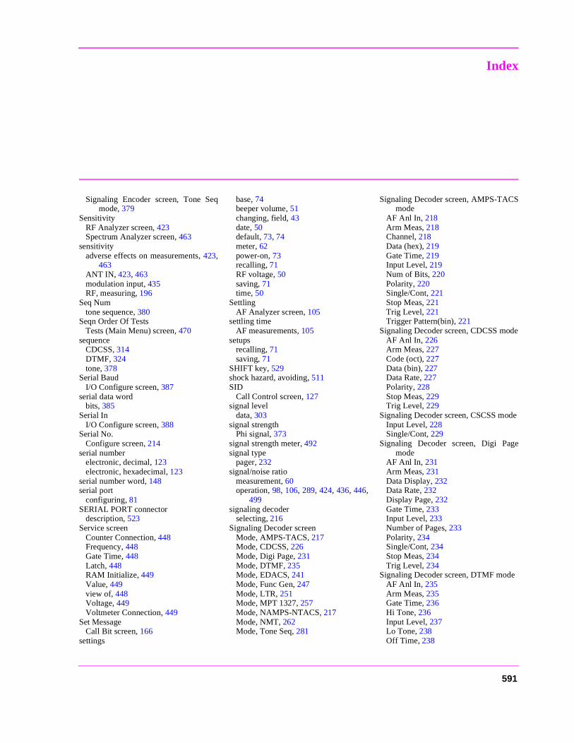
Index
Signaling Encoder screen, Tone Seqmode, 379
SensitivityRF Analyzer screen, 423Spectrum Analyzer screen, 463
sensitivityadverse effects on measurements, 423,
463ANT IN, 423, 463modulation input, 435RF, measuring, 196
Seq Numtone sequence, 380
Seqn Order Of TestsTests (Main Menu) screen, 470
sequenceCDCSS, 314DTMF, 324tone, 378
Serial BaudI/O Configure screen, 387
serial data wordbits, 385
Serial InI/O Configure screen, 388
Serial No.Configure screen, 214
serial numberelectronic, decimal, 123electronic, hexadecimal, 123
serial number word, 148serial port
configuring, 81SERIAL PORT connector
description, 523Service screen
Counter Connection, 448Frequency, 448Gate Time, 448Latch, 448RAM Initialize, 449Value, 449view of, 448Voltage, 449Voltmeter Connection, 449
Set MessageCall Bit screen, 166
settings
base, 74beeper volume, 51changing, field, 43date, 50default, 73, 74meter, 62power-on, 73recalling, 71RF voltage, 50saving, 71time, 50
SettlingAF Analyzer screen, 105
settling timeAF measurements, 105
setupsrecalling, 71saving, 71
SHIFT key, 529shock hazard, avoiding, 511SID
Call Control screen, 127signal level
data, 303signal strength
Phi signal, 373signal strength meter, 492signal type
pager, 232signal/noise ratio
measurement, 60operation, 98, 106, 289, 424, 436, 446,
499signaling decoder
selecting, 216Signaling Decoder screen
Mode, AMPS-TACS, 217Mode, CDCSS, 226Mode, Digi Page, 231Mode, DTMF, 235Mode, EDACS, 241Mode, Func Gen, 247Mode, LTR, 251Mode, MPT 1327, 257Mode, NAMPS-NTACS, 217Mode, NMT, 262Mode, Tone Seq, 281
Signaling Decoder screen, AMPS-TACSmode
AF Anl In, 218Arm Meas, 218Channel, 218Data (hex), 219Gate Time, 219Input Level, 219Num of Bits, 220Polarity, 220Single/Cont, 221Stop Meas, 221Trig Level, 221Trigger Pattern(bin), 221
Signaling Decoder screen, CDCSS modeAF Anl In, 226Arm Meas, 227Code (oct), 227Data (bin), 227Data Rate, 227Polarity, 228Stop Meas, 229Trig Level, 229
Signaling Decoder screen, CSCSS modeInput Level, 228Single/Cont, 229
Signaling Decoder screen, Digi Pagemode
AF Anl In, 231Arm Meas, 231Data Display, 232Data Rate, 232Display Page, 232Gate Time, 233Input Level, 233Number of Pages, 233Polarity, 234Single/Cont, 234Stop Meas, 234Trig Level, 234
Signaling Decoder screen, DTMF modeAF Anl In, 235Arm Meas, 235Gate Time, 236Hi Tone, 236Input Level, 237Lo Tone, 238Off Time, 238
591
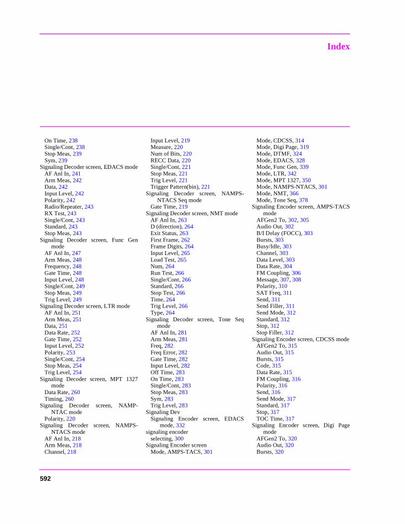
Index
On Time, 238Single/Cont, 238Stop Meas, 239Sym, 239
Signaling Decoder screen, EDACS modeAF Anl In, 241Arm Meas, 242Data, 242Input Level, 242Polarity, 242Radio/Repeater, 243RX Test, 243Single/Cont, 243Standard, 243Stop Meas, 243
Signaling Decoder screen, Func Genmode
AF Anl In, 247Arm Meas, 248Frequency, 248Gate Time, 248Input Level, 248Single/Cont, 249Stop Meas, 249Trig Level, 249
Signaling Decoder screen, LTR modeAF Anl In, 251Arm Meas, 251Data, 251Data Rate, 252Gate Time, 252Input Level, 252Polarity, 253Single/Cont, 254Stop Meas, 254Trig Level, 254
Signaling Decoder screen, MPT 1327mode
Data Rate, 260Timing, 260
Signaling Decoder screen, NAMP-NTAC mode
Polarity, 220Signaling Decoder screen, NAMPS-
NTACS modeAF Anl In, 218Arm Meas, 218Channel, 218
Input Level, 219Measure, 220Num of Bits, 220RECC Data, 220Single/Cont, 221Stop Meas, 221Trig Level, 221Trigger Pattern(bin), 221
Signaling Decoder screen, NAMPS-NTACS Seq mode
Gate Time, 219Signaling Decoder screen, NMT mode
AF Anl In, 263D (direction), 264Exit Status, 263First Frame, 262Frame Digits, 264Input Level, 265Load Test, 265Num, 264Run Test, 266Single/Cont, 266Standard, 266Stop Test, 266Time, 264Trig Level, 266Type, 264
Signaling Decoder screen, Tone Seqmode
AF Anl In, 281Arm Meas, 281Freq, 282Freq Error, 282Gate Time, 282Input Level, 282Off Time, 283On Time, 283Single/Cont, 283Stop Meas, 283Sym, 283Trig Level, 283
Signaling DevSignaling Encoder screen, EDACS
mode, 332signaling encoder
selecting, 300Signaling Encoder screen
Mode, AMPS-TACS, 301
Mode, CDCSS, 314Mode, Digi Page, 319Mode, DTMF, 324Mode, EDACS, 328Mode, Func Gen, 339Mode, LTR, 342Mode, MPT 1327, 350Mode, NAMPS-NTACS, 301Mode, NMT, 366Mode, Tone Seq, 378
Signaling Encoder screen, AMPS-TACSmode
AFGen2 To, 302, 305Audio Out, 302B/I Delay (FOCC), 303Bursts, 303Busy/Idle, 303Channel, 303Data Level, 303Data Rate, 304FM Coupling, 306Message, 307, 308Polarity, 310SAT Freq, 311Send, 311Send Filler, 311Send Mode, 312Standard, 312Stop, 312Stop Filler, 312
Signaling Encoder screen, CDCSS modeAFGen2 To, 315Audio Out, 315Bursts, 315Code, 315Data Rate, 315FM Coupling, 316Polarity, 316Send, 316Send Mode, 317Standard, 317Stop, 317TOC Time, 317
Signaling Encoder screen, Digi Pagemode
AFGen2 To, 320Audio Out, 320Bursts, 320
592
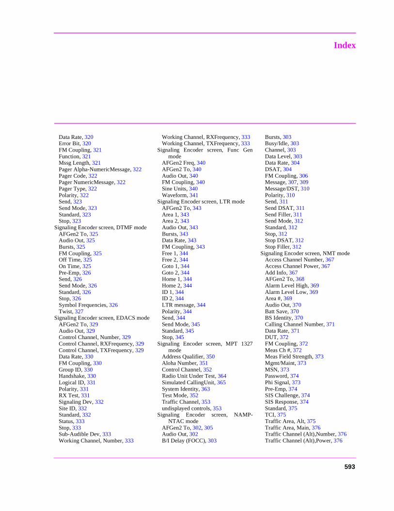
Index
Data Rate, 320Error Bit, 320FM Coupling, 321Function, 321Mssg Length, 321Pager Alpha-NumericMessage, 322Pager Code, 322Pager NumericMessage, 322Pager Type, 322Polarity, 322Send, 323Send Mode, 323Standard, 323Stop, 323
Signaling Encoder screen, DTMF modeAFGen2 To, 325Audio Out, 325Bursts, 325FM Coupling, 325Off Time, 325On Time, 325Pre-Emp, 326Send, 326Send Mode, 326Standard, 326Stop, 326Symbol Frequencies, 326Twist, 327
Signaling Encoder screen, EDACS modeAFGen2 To, 329Audio Out, 329Control Channel, Number, 329Control Channel, RXFrequency, 329Control Channel, TXFrequency, 329Data Rate, 330FM Coupling, 330Group ID, 330Handshake, 330Logical ID, 331Polarity, 331RX Test, 331Signaling Dev, 332Site ID, 332Standard, 332Status, 333Stop, 333Sub-Audible Dev, 333Working Channel, Number, 333
Working Channel, RXFrequency, 333Working Channel, TXFrequency, 333
Signaling Encoder screen, Func Genmode
AFGen2 Freq, 340AFGen2 To, 340Audio Out, 340FM Coupling, 340Sine Units, 340Waveform, 341
Signaling Encoder screen, LTR modeAFGen2 To, 343Area 1, 343Area 2, 343Audio Out, 343Bursts, 343Data Rate, 343FM Coupling, 343Free 1, 344Free 2, 344Goto 1, 344Goto 2, 344Home 1, 344Home 2, 344ID 1, 344ID 2, 344LTR message, 344Polarity, 344Send, 344Send Mode, 345Standard, 345Stop, 345
Signaling Encoder screen, MPT 1327mode
Address Qualifier, 350Aloha Number, 351Control Channel, 352Radio Unit Under Test, 364Simulated CallingUnit, 365System Identity, 363Test Mode, 352Traffic Channel, 353undisplayed controls, 353
Signaling Encoder screen, NAMP-NTAC mode
AFGen2 To, 302, 305Audio Out, 302B/I Delay (FOCC), 303
Bursts, 303Busy/Idle, 303Channel, 303Data Level, 303Data Rate, 304DSAT, 304FM Coupling, 306Message, 307, 309Message/DST, 310Polarity, 310Send, 311Send DSAT, 311Send Filler, 311Send Mode, 312Standard, 312Stop, 312Stop DSAT, 312Stop Filler, 312
Signaling Encoder screen, NMT modeAccess Channel Number, 367Access Channel Power, 367Add Info, 367AFGen2 To, 368Alarm Level High, 369Alarm Level Low, 369Area #, 369Audio Out, 370Batt Save, 370BS Identity, 370Calling Channel Number, 371Data Rate, 371DUT, 372FM Coupling, 372Meas Ch #, 372Meas Field Strength, 373Mgmt/Maint, 373MSN, 373Password, 374Phi Signal, 373Pre-Emp, 374SIS Challenge, 374SIS Response, 374Standard, 375TCI, 375Traffic Area, Alt, 375Traffic Area, Main, 376Traffic Channel (Alt),Number, 376Traffic Channel (Alt),Power, 376
593
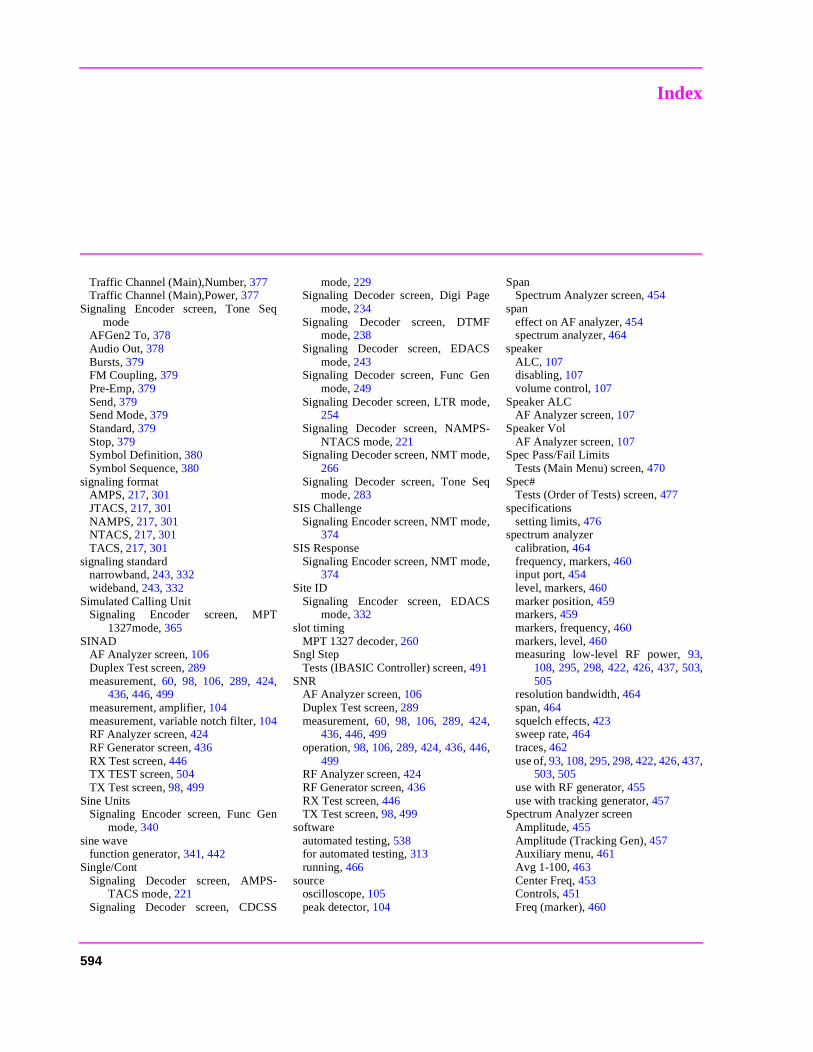
Index
Traffic Channel (Main),Number, 377Traffic Channel (Main),Power, 377
Signaling Encoder screen, Tone Seqmode
AFGen2 To, 378Audio Out, 378Bursts, 379FM Coupling, 379Pre-Emp, 379Send, 379Send Mode, 379Standard, 379Stop, 379Symbol Definition, 380Symbol Sequence, 380
signaling formatAMPS, 217, 301JTACS, 217, 301NAMPS, 217, 301NTACS, 217, 301TACS, 217, 301
signaling standardnarrowband, 243, 332wideband, 243, 332
Simulated Calling UnitSignaling Encoder screen, MPT
1327mode, 365SINAD
AF Analyzer screen, 106Duplex Test screen, 289measurement, 60, 98, 106, 289, 424,
436, 446, 499measurement, amplifier, 104measurement, variable notch filter, 104RF Analyzer screen, 424RF Generator screen, 436RX Test screen, 446TX TEST screen, 504TX Test screen, 98, 499
Sine UnitsSignaling Encoder screen, Func Gen
mode, 340sine wave
function generator, 341, 442Single/Cont
Signaling Decoder screen, AMPS-TACS mode, 221
Signaling Decoder screen, CDCSS
mode, 229Signaling Decoder screen, Digi Page
mode, 234Signaling Decoder screen, DTMF
mode, 238Signaling Decoder screen, EDACS
mode, 243Signaling Decoder screen, Func Gen
mode, 249Signaling Decoder screen, LTR mode,
254Signaling Decoder screen, NAMPS-
NTACS mode, 221Signaling Decoder screen, NMT mode,
266Signaling Decoder screen, Tone Seq
mode, 283SIS Challenge
Signaling Encoder screen, NMT mode,374
SIS ResponseSignaling Encoder screen, NMT mode,
374Site ID
Signaling Encoder screen, EDACSmode, 332
slot timingMPT 1327 decoder, 260
Sngl StepTests (IBASIC Controller) screen, 491
SNRAF Analyzer screen, 106Duplex Test screen, 289measurement, 60, 98, 106, 289, 424,
436, 446, 499operation, 98, 106, 289, 424, 436, 446,
499RF Analyzer screen, 424RF Generator screen, 436RX Test screen, 446TX Test screen, 98, 499
softwareautomated testing, 538for automated testing, 313running, 466
sourceoscilloscope, 105peak detector, 104
SpanSpectrum Analyzer screen, 454
spaneffect on AF analyzer, 454spectrum analyzer, 464
speakerALC, 107disabling, 107volume control, 107
Speaker ALCAF Analyzer screen, 107
Speaker VolAF Analyzer screen, 107
Spec Pass/Fail LimitsTests (Main Menu) screen, 470
Spec#Tests (Order of Tests) screen, 477
specificationssetting limits, 476
spectrum analyzercalibration, 464frequency, markers, 460input port, 454level, markers, 460marker position, 459markers, 459markers, frequency, 460markers, level, 460measuring low-level RF power, 93,
108, 295, 298, 422, 426, 437, 503,505
resolution bandwidth, 464span, 464squelch effects, 423sweep rate, 464traces, 462use of, 93, 108, 295, 298, 422, 426, 437,
503, 505use with RF generator, 455use with tracking generator, 457
Spectrum Analyzer screenAmplitude, 455Amplitude (Tracking Gen), 457Auxiliary menu, 461Avg 1-100, 463Center Freq, 453Controls, 451Freq (marker), 460
594
Index
Input Atten, 461Lvl (marker), 460Main menu, 453Marker menu, 459Marker To, 459No Pk/Avg, 463Normalize, 462Offset Freq (Tracking Gen), 458Output Port (RF Gen), 456Pk Hold, 463Port/Sweep (Tracking Gen), 458Position, 459Ref Level, 453RF Gen Freq, 456RF In/Ant, 454Sensitivity, 463Span, 454view of, 452
spursACP measurement, 92
square wavefunction generator, 341
SquelchRF Analyzer screen, 423
squelchCDCSS, 314digital decoding, 226effects on decoder, 423effects on HP-IB operation, 424effects on oscilloscope, 423effects on remote operation, 424effects on spectrum analyzer, 423fixed level, 423manual control, 423off, 423using attenuator hold, 291, 434, 444
squelch control, 530Standard
Signaling Decoder screen, EDACSmode, 243
Signaling Decoder screen, NMT mode,266
Signaling Encoder screen, AMPS-TACS mode, 312
Signaling Encoder screen, CDCSSmode, 317
Signaling Encoder screen, Digi Pagemode, 323
Signaling Encoder screen, DTMFmode, 326
Signaling Encoder screen, EDACSmode, 332
Signaling Encoder screen, LTR mode,345
Signaling Encoder screen, NAMP-NTAC mode, 312
Signaling Encoder screen, NMT mode,375
Signaling Encoder screen, Tone Seqmode, 379
station class mark, 127Status
Signaling Encoder screen, EDACSmode, 333
statuscontrol, 333idle, 333indicators, 317working, 333
STD450 NMT radio standard, 269, 375STD900 NMT radio standard, 269, 375Step#
Tests (Order of Tests) screen, 475Stop
Signaling Encoder screen, AMPS-TACS mode, 312
Signaling Encoder screen, CDCSSmode, 317
Signaling Encoder screen, Digi Pagemode, 323
Signaling Encoder screen, DTMFmode, 326
Signaling Encoder screen, EDACSmode, 333
Signaling Encoder screen, LTR mode,345
Signaling Encoder screen, NAMP-NTAC mode, 312
Signaling Encoder screen, Tone Seqmode, 379
stop bit, 388Stop DSAT
Signaling Encoder screen, NAMP-NTAC mode, 312
Stop FillerSignaling Encoder screen, AMPS-
TACS mode, 312Signaling Encoder screen, NAMP-
NTAC mode, 312Stop Length
I/O Configure screen, 388Stop Meas
Signaling Decoder screen, AMPS-TACS mode, 221
Signaling Decoder screen, CDCSSmode, 229
Signaling Decoder screen, Digi Pagemode, 234
Signaling Decoder screen, DTMFmode, 239
Signaling Decoder screen, EDACSmode, 243
Signaling Decoder screen, Func Genmode, 249
Signaling Decoder screen, LTR mode,254
Signaling Decoder screen, NAMPS-NTACS mode, 221
Signaling Decoder screen, Tone Seqmode, 283
Stop TestSignaling Decoder screen, NMT mode,
266Strobe Pol
Radio Interface screen, 408Sub-Audible Dev
Signaling Encoder screen, EDACSmode, 333
subscriber identity security challenge,374
subscriber identity security response, 374subscriber number, 373support, 546Support Contacts
electronic mail, 9HP Desk, 9telephone, 9
sweepfrequency range, tracking generator,
454oscilloscope, 393rate, spectrum analyzer, 464time per division, 393tracking generator, 458
595
Index
SymSignaling Decoder screen, DTMF
mode, 239Signaling Decoder screen, Tone Seq
mode, 283symbol
for tone sequence, 239, 283, 380frequency, 239, 282, 283frequency error, 282hexadecimal number, 380
Symbol DefinitionSignaling Encoder screen, Tone Seq
mode, 380Symbol Frequencies
Signaling Encoder screen, DTMFmode, 326
Symbol SequenceSignaling Encoder screen, Tone Seq
mode, 380sync delay
word, 303synchronization sequence
decoder, MPT 1327, 259syntax
NMT programming, 277system identification number, 127System Identity
Signaling Encoder screen, MPT 1327mode, 363
system parameter overhead word 2 mes-sage, 169
System TypeCall Control screen, 128
TTA1, main traffic area, 271TA2, alternate traffic area, 271talk & listen, 386tariff class information, 375TC1, main traffic channel, 271TC2, alternate traffic channel, 271TCI
Signaling Encoder screen, NMT mode,375
terminal, ASCII, 81Test Mode
Signaling Encoder screen, MPT 1327mode, 352
Test NameTests (Order of Tests) screen, 475
Test Procedure Run ModeTests (Execution Conditions) screen,
483test set
configuring, 49test subsystem, 467Tests (Channel Information) screen, 467
Delete Ch, 472Insert Ch, 472Main Menu, 472, 473Print All, 472, 473view of, 471
Tests (Execution Conditions) screen, 467Autostart Test Procedureon Power-Up,
482Continue, 482If Unit-Under-Test Fails, 482Main Menu, 482Output Heading, 482Output Results For, 483Output Results To, 482Run Test, 483Test Procedure Run Mode, 483view of, 481
Tests (External Devices) screen, 467Addr, 485Calling Name, 485Delet Ins, 485External Disk Specification, 485Insrt Ins, 485Inst#, 486Main Menu, 486
Model, 486Options, 486Output Heading, 486view of, 484
Tests (IBASIC Controller) screen, 467Clr Scr, 491Continue, 491Main Menu, 491Sngl Step, 491view of, 490
Tests (Main Menu) screen, 467Cnfg External Devices, 468Continue, 468Description, 468Exec Execution Cond, 468Freq Channel Information, 469IBASIC IBASIC Cntrl, 469Library, 469Parm Test Parameters, 469Pass/Fail Limits, 470Print Printer Setup, 469Proc Save/Delete Procedure, 470Program, 470Run Test, 470Select Procedure Filename, 470Select Procedure Location, 470Seqn Order of Tests, 470view of, 468
Tests (Order of Tests) screen, 467All Chans?, 474Delet Stp, 475Insrt Stp, 475Main Menu, 475Output Heading, 475Spec#, 477Step#, 475Test Name, 475view of, 474
Tests (Pass/Fail Limits) screen, 467Check, 477Lower Limit, 477Main Menu, 477Output Heading, 477Units, 477Upper Limit, 477view of, 476
Tests (Printer Setup) screen, 467Continue, 487
596
Index
FF at End, 487FF at Start, 487Lines/Page, 488Main Menu, 488Model, 488Output Heading, 488Output Results For, 488Output Results To, 488Printer Address, 489Printer Port, 489Run, 491Run Test, 489view of, 487
Tests (Save/Delete Procedure) screen,467
Code Location, 479Enter Procedure Filename, 479Main Menu, 479Pass Word, 479Select ProcedureLocation, 480view of, 478
Tests (Test Parameters) screen, 467view of, 473
TESTS key, 528Time
Configure screen, 50, 214Signaling Decoder screen, NMT mode,
264time
markers, 395Time (marker)
Oscilloscope screen, 395time and date, 50Time/div
Oscilloscope screen, 393timebase
decoder, 216external input, 525external output, 525
timerlow battery, 51
TimingSignaling Decoder screen, MPT 1327
mode, 260timing
response, MPT 1327 decoder, 261slot, MPT 1327 decoder, 260
title
for printout, 401, 488TOC
defined, 227TOC Time
Signaling Encoder screen, CDCSSmode, 317
tone lengthDTMF encoder, 325tone sequence decoder, 238, 283Tone Sequence endcoder, 380
tone sequenceburst, 312, 317, 323, 326, 345, 379continuous, 312, 323, 326, 345, 379editing, 380entering, 380outputting, 379single, 312, 317, 323, 326, 345, 379stepped, 312, 326, 345, 379stopping, 312, 317, 323, 326, 345, 379symbol frequency, 282symbol frequency error, 282using frequencies, 380using hexadecimal numbers, 380using relative amplitude, 380
Tone Sequence decoder modeAF Anl In, 281Arm Meas, 281Freq, 282Freq Error, 282Gate Time, 282Input Level, 282Off Time, 283On Time, 283Single/Cont, 283Stop Meas, 283Sym, 283Trig Level, 283view of, 281
Tone Sequence encoder modeAFGen2 To, 378Audio Out, 378Bursts, 379FM Coupling, 379Pre-Emp, 379Send, 379Send Mode, 379Standard, 379Stop, 379
Symbol Definition, 380Symbol Sequence, 380view of, 378
tone-only operationdigital paging, 321
total access communication system forJapan
decoder, 217encoder, 301
total access communications systemsdecoder, 217encoder, 301
Total RAMConfigure screen, 214
tracecomparison, spectrum analyzer, 462spectrum analyzer, 462
tracking generatoramplitude, 457frequency, 453frequency offset, 458offset, 457output, 458output port, 458sweep, 458use with spectrum analyzer, 457
Traffic Area, AltSignaling Encoder screen, NMT mode,
375Traffic Area, Main
Signaling Encoder screen, NMT mode,376
Traffic ChannelSignaling Encoder screen, MPT 1327
mode, 353traffic channel
channel number, NMT, 371Traffic Channel (Alt), Number
Signaling Encoder screen, NMTmode,376
Traffic Channel (Alt), PowerSignaling Encoder screen, NMTmode,
376Traffic Channel (Main), Number
Signaling Encoder screen, NMTmode,377
Traffic Channel (Main), PowerSignaling Encoder screen, NMTmode,
597
Index
377training, 546transmit pace, 388transmitter
keying, 90, 294, 420, 502transmitter frequency, 58
measurement, 93, 107, 298, 425, 437,505
transmitter frequency error, 58measurement, 93, 107, 298, 425, 437,
505transmitter power, 58
fast (HP 8920B), 427, 505measurement, 93, 108, 298, 426, 437,
505mobile station, 136modulation quality, 121zero reference, 94, 427, 506
transmitter testingEDACS, 244
triangle wavefunction generator, 341
Trig LevelSignaling Decoder screen, AMPS-
TACS mode, 221Signaling Decoder screen, CDCSS
mode, 229Signaling Decoder screen, Digi Page
mode, 234Signaling Decoder screen, Func Gen
mode, 249Signaling Decoder screen, LTR mode,
254Signaling Decoder screen, NAMPS-
NTACS mode, 221Signaling Decoder screen, NMT mode,
266Signaling Decoder screen, Tone Seq
mode, 283Trigger Pattern (bin)
Signaling Decoder screen, AMPS-TACSmode, 221
Signaling Decoder screen, NAMPS-NTACSmode, 221
triggeringautomatic, 396bit position, 221continuous, 397
decoder, AMPS-TACS/NAMPS-NTACS, 218, 221
decoder, CDCSS, 227, 229decoder, digital paging, 231, 234decoder, DTMF, 235, 238decoder, EDACS, 242, 243decoder, function generator, 248, 249decoder, LTR, 251, 254decoder, MPT 1327, 258decoder, NMT, 266decoder, tone sequence, 281, 283display, 397encoder, oscilloscope, 396external, oscilloscope, 396gate time, 219, 233, 236, 248, 252, 282input level, 219, 228, 233, 237, 242,
248, 252, 265, 282internal, 397internal, oscilloscope, 396level, 221, 229, 234, 249, 254, 266,
283, 396negative edge, 397NMT alarm, 369positive edge, 397radio interface, 406signal, 396source, oscilloscope, 396time, 395
troubleshooting, 448trunked receiver channel
home channel, 347trunked transmit channel
home channel, 348trunking data, 342trunking message, 342Tune Freq
Adjacent Channel Power screen, 92Duplex Test screen, 297RF Analyzer screen, 425TX Test screen, 504
Tune ModeAdjacent Channel Power screen, 92Duplex Test screen, 297RF Analyzer screen, 425TX Test screen, 504
tuningautomatic, 92, 297, 425, 504channel, automatic, 210
manual, 92, 297, 425, 504turn off code
CDCSS encoder, 318frequency, 315output time, 317
turning off squelch, 423Twist
Signaling Encoder screen, DTMFmode, 327
twistrecommended settings, 327
twist and pre-emphasisinteractions, 327
TX Freq ErrorAdjacent Channel Power screen, 93AF Analyzer screen, 107Analog Meas screen, 194Call Control screen, 128Duplex Test screen, 298RF Analyzer screen, 425RF Generator screen, 437TX Test screen, 505
TX FrequencyAdjacent Channel Power screen, 93AF Analyzer screen, 107Duplex Test screen, 298RF Analyzer screen, 425RF Generator screen, 437TX Test screen, 505
TX key, 528TX Power
Adjacent Channel Power screen, 93AF Analyzer screen, 108Analog Meas screen, 194Call Control screen, 128Duplex Test screen, 298RF Analyzer screen, 426RF Generator screen, 437TX Test screen, 505
TX Pwr Meas (HP 8920B)RF Analyzer screen, 427TX Test screen, 505
TX Pwr ZeroAdjacent Channel Power screen, 94Call Configuration screen, 199RF Analyzer screen, 427TX Test screen, 506
TX TEST screen
598
Index
Current, 500DC Level, 500Distortion, 502SINAD, 504
TX Test Screenview of, 497
TX Test screenAF Anl In, 498AF Freq, 98, 499AFGen1 Freq, 500AFGen1 Lvl, 500Current, 98, 499DC Level, 98, 499De-emphasis, 500Detector, 501Distn, 98, 499Ext TX key, 502Filter 1 and Filter 2, 502FM Deviation, 502functional block diagram, 497IF Filter, 502Input Port, 503priority settings, 54SINAD, 98, 499SNR, 98, 499Tune Freq, 504Tune Mode, 504TX Freq Error, 505TX Frequency, 505TX Power, 505TX Pwr Meas (HP 8920B), 505TX Pwr Zero, 506
TypeSignaling Decoder screen, NMT mode,
264type bits, 306, 308
Uundisplayed controls
Signaling Encoder screen, MPT 1327mode, 353
unit-of-measurechanging, 61, 64converting, 61, 64keys, 526
UnitsTests (Pass/Fail Limits) screen, 477
unitspeak, 340rms, 340
universal noisefunction generator, 341
up arrow key, 527upgrades
firmware, 534hardware, 532
Upper LimitTests (Pass/Fail Limits) screen, 477
User Def Base FreqConfigure screen, 203
user keysassigning global, 78assigning, local, 77clearing, global assignment, 78clearing, local assignment, 77deleting, global assignment, 78deleting, local assignment, 77example, 77explanation, 75global, assignment, 78global, defined, 75local, assignment, 77local, defined, 75preassigned, 76releasing, global assignment, 78releasing, local assignment, 77setting, global, 78setting, local, 77
VV
displaying results in, 61V (volts)
displaying results in, 61Value
Service screen, 449variable frequency notch filter, 104version number
firmware, 205Vert Offset
Oscilloscope screen, 393Vert/div
Oscilloscope screen, 393vertical offset
oscilloscope, 393, 395vertical sensitivity
oscilloscope, 393video averaging
spectrum analyzer, 463VMAC
power level, 125voice channel assignment, 120voice channel decoder
AMPS-TACS, 217NAMPS-NTACS, 217
voice guard, 241Voltage
Service screen, 449voltage
measurement, 97, 431, 442RF, across 50 ohm load, 210RF, emf (open circuit), 210setting, 50
Voltmeter ConnectionService screen, 449
volumebeeper, 51, 204control, 530internal speaker, 107
599
Index
WW (watts)
displaying results in, 61Waveform
Signaling Encoder screen, Func Genmode, 341
waveformdc, 341Gaussian noise, 341selecting, 341sine, 341square, 341triangle, 341universal noise, 341
widebanddecoder, signaling standard, 243encoder, signaling standard, 332
wordabbreviated address, 144extended address, 146first word of called address, 149reverse voice channel order confirma-
tion message, 151second word of called address, 150serial number, 148to view, from mobile station handoff,
156to view, from mobile station origina-
tion, 160to view, from mobile station page, 154to view, from mobile station registra-
tion, 153to view, from mobile station release,
158to view, from order to change TX pow-
er of mobile, 159word sync bits, 306, 308word sync delay, 303working
status, 333Working Channel, Number
Signaling Encoder screen, EDACSmode, 333
Working Channel, RX FrequencySignaling Encoder screen, EDACS-
mode, 333Working Channel, TX Frequency
Signaling Encoder screen, EDACS-
mode, 333 XXmt Pace
I/O Configure screen, 388Xon/Xoff, 386, 388
600
Index
YYES key, 526
Zzero crossing
detecting, 228zero reference
tranmitter power, 94, 427, 506zeroing
DCFM, 434measurement offset, 99power meter, 94, 130, 427, 506
ZVEI1radio standard, 379
ZVEI2radio standard, 379
601


