
UNIVERSITI TEKNIKAL MALAYSIA MELAKA
BIKER COMMUNICATION DEVICE
This report submitted in accordance with requirement of the Universiti Teknikal
Malaysia Melaka (UTeM) for the Bachelor Degree of Electronic Engineering
Technology (Telecommunication) (Hons.)
by
MOHAMAD SYAZWAN BIN AHMAD YUSRI
B071210100
930204-02-5957
FACULTY OF ENGINEERING TECHNOLOGY
2015

UNIVERSITI TEKNIKAL MALAYSIA
MELAKA BORANG PENGESAHAN STATUS LAPORAN PROJEK SARJANA MUDA
TAJUK: Biker Communication Device SESI PENGAJIAN: 2015/16 Semester 2 Saya MOHAMAD SYAZWAN BIN AHMAD YUSRI mengaku membenarkan Laporan PSM ini disimpan di Perpustakaan Universiti Teknikal Malaysia Melaka (UTeM) dengan syarat-syarat kegunaan seperti berikut:
1. Laporan PSM adalah hak milik Universiti Teknikal Malaysia Melaka dan penulis. 2. Perpustakaan Universiti Teknikal Malaysia Melaka dibenarkan membuat salinan
untuk tujuan pengajian sahaja dengan izin penulis. 3. Perpustakaan dibenarkan membuat salinan laporan PSM ini sebagai bahan
pertukaran antara institusi pengajian tinggi.
4. **Sila tandakan ( )
SULIT
TERHAD
TIDAK TERHAD
(Mengandungi maklumat yang berdarjah keselamatan atau kepentingan Malaysia sebagaimana yang termaktub dalam AKTA RAHSIA RASMI 1972)
(Mengandungi maklumat TERHAD yang telah ditentukan oleh organisasi/badan di mana penyelidikan dijalankan)
Alamat Tetap:
No. 204 Felda Teloi Kanan,
09300 Kuala Ketil,
Kedah Darul Aman.
Tarikh: _______________________
Disahkan oleh:
Cop Rasmi: Tarikh: _______________________
** Jika Laporan PSM ini SULIT atau TERHAD, sila lampirkan surat daripada pihak berkuasa/organisasi berkenaan dengan menyatakan sekali sebab dan tempoh laporan PSM ini perlu dikelaskan sebagai SULIT atau TERHAD.

DECLARATION
I hereby, declared this report entitled “Biker Communication Device” is the results
of my own research except as cited in references.
Signature : ………………………………………….
Author’s Name : MOHAMAD SYAZWAN BIN AHMAD YUSRI
Date :

APPROVAL
This report is submitted to the Faculty of Engineering Technology of UTeM as a
partial fulfillment of the requirements for the degree of Bachelor in Electronic
Engineering Technology (Telecommunication) (Hons). The member of the
supervisory is as follow:
…………………………………………………………..
(Abdul Halim Bin Dahalan)

i
ABSTRAK
Walkie-talkie ialah satu radio mudah alih yang akan berkomunikasi secara tanpa
wayar di dalam satu,laluan dan berkongsi jalur frekuensi. Setiap frekuensi yang akan
digunakan ialah mesti tidak bertindih dengan frekuensi yang lain kerana hendak
mengelak dari kecelaruan frekuensi. Walkie-talkie menggunakan pemancar dan litar
penerima yang menggunakan tenaga bateri.untuk menghidupkannya Terdapat
beberapa komponen yang melengkapkan satu set walkie-talkie seperti sebuah
mikrofon, pembesar suara dan satu desakan untuk butang bual yang akan membuat
pengguna boleh berkomunikasi dan mendengar suara. Tambahan pula, dengan
kecanggihan teknologi sekarang ini dapatlah mereka bentuk atau melaksanakan
rekaan terbaru yang boleh membuat pengguna boleh menggunakan ia di atas jalan
raya dengan mudah. Misalnya, pengguna yang selalu menghabiskan masa di hujung
minggu dengan aktiviti-aktiviti konvoi. Rekaan terbaru akan membangunkan. Peranti
ini untuk penunggang bagi pastikan ia akan menjadi mudah digunakan semasa
mempunyai perjalanan mereka dan ia juga boleh mengelak penunggang dari
berlakunya kemalangan kerana tidak menumpukan sepenuh perhatian semasa
aktiviti konvoi. Peranti ini akan dinamakan sebagai Biker Communication Device.
Peranti ini akan dipasang di topi keledar dan ia juga hanya menggunakan satu saluran
kerana hendak mengelak lebihan frekuensi. Peranti juga boleh membuat penunggang
mudah menggunakannya kerana ia hanya tekan tolakan untuk butang bual dan
bercakap dan pengguna lain akan menerima suara dan peranti tidak perlu dipegang
dengan tangan dan ia akan memastikan penunggang memberi sepenuh perhatian
semasa melakukan aktiviti konvoi dan daripada itu ia dapat mengelakkan
kemalangan semasa aktiviti konvoi.

ii
ABSTRACT
The walkie-talkie is a portable radio that will communicate wirelessly on a single,
shared frequency band. Every frequency that will be use is must do not overlap with
the other frequency because want to avoid from the distortion. The walkie-talkie is
using the transmitter and the receiver circuit that powered up by the battery. There
are the component that will complete one set of walkie-talkie such as a microphone,
speaker and a push to talk button that will make the user can communicate and hear
the voice. Furthermore, with the advance of the technology nowadays there are
respected to design or implement the new device that can make the user can use it in
a easy way. For example, the user that always spent time on weekend with the
convoy activities. So that, the new device will be develop. This device is for the rider
to make sure it will be easy to use while having their journey and it also can avoid
the rider cause an accident because do not concentrate when having the convoy
activities. This device will be name as Biker Communication Device. This device
will be installed at the helmet and it also just using one channel because wants to
avoid the redundancy of the frequency. The device also can make the rider easy to
use because it just press the push to talk button and speak and the another user will
receive the voice and the device do not hold with the hands and it will make the rider
give full attention when having their activities and from that the causes of the
accident cause by the convoy activities will be reduce.
iii
DEDICATION
Alhamdulillah, praise to the Almighty Allah S.W.T
This thesis is dedicated to:
My beloved family,
My Parents,
My Supervisor,
My lecturers
And all my friends
Thanks for their encouragement and support

iv
ACKNOWLEDGEMENT
Alhamdulillah, thank you Allah because of Your Blessing and give me strength to
complete and finish my final year project with successfully.
During the process to complete my project objective, I do a lot of research either by
using internet, reading past year thesis, reference books and journal. With the
guidance and support from peoples around me, I finally complete the project due to
the time given. Here, I want to give credit to those who helped me to achieve what I
had achieved in my final year project.
I would like to express my gratitude and appreciation to all those who gave me the
possibility to complete this report. A special thanks to my supervisor, Mr Abdul
Halim Bin Dahalan, whose help, stimulating suggestion and encouragement, helped
me to coordinate my project especially in writing this report.
I would also like to acknowledge with much appreciation the crucial role of the staff
of Radio Frequency Laboratory, who gave me permission to use the spectrum
analyser to complete my analysis.
I also want to thanks to my beloved parents because without them, I will not be able
to do well in my final year project. They did give me a lot of support, both from
money and moral support to help me continue for what I had started on.
Thank you to all lecturers, staffs, friends and all who has directly and indirectly
involved on this project. Your helps and cooperation will never be forgotten. May
Allah bless and reward them for their sincere, endeavour and contribution in the way
of knowledge.
v
TABLE OF CONTENT
Abstrak i
Abstract ii
Dedication iii
Acknowledgement iv
Table of Content v
List of Tables viii
List of Figures ix
List Abbreviations, Symbols and Nomenclatures xi
CHAPTER 1: 1INTRODUCTION
1.1 Introduction 1
1.2 Background Project 2
1.3 Problem Statement 3
1.4 Objective 4
1.5 Work Scope 5
1.6 Project Significant 6
1.7 Report Organizations 6
CHAPTER 2: LITERATURE REVIEW
2.1 Introduction 8
2.2 Application of Walkie-Talkie 9
2.3 Walkie-Talkie Application upon Android Device 9
2.3.1 The Historical Overview 10
2.4 Walkie-Talkie: Vehicular Communication System 13
2.5 A Multi-Hop Walkie-Talkie Emergency Communication 14
2.5.1 Project Overview 15
2.6 New Walkie-Talkie Uses Sub miniatures Vacuum Tubes 16
2.7 Civil Digital Walkie-Talkie 17
2.8 Biker Communication Device 18

vi
2.8.1 The Transmitter 19
2.8.2 The Receiver 19
2.8.3 Multisim Software 20
2.8.4 PCB Wizard 20
2.9 Summary 20
CHAPTER 3: METHODOLOGY
3.1 Project Overview 22
3.2 Project Implementation 22
3.2.1 Block Diagram 22
3.2.2 Gantt Chart 23
3.2.3 Flowchart of Project Implement 24
3.3 Software Implementation 25
3.4 Hardware Implementation 26
3.4.1 Hardware Requirement 26
3.5 Hardware Development 28
3.5.1 Resistor 28
3.5.2 Disc Ceramic 29
3.5.3 Electrolytic Capacitor 30
3.5.4 Transistor 31
3.6 Inductor, RF transformer and Switch 31
3.7 The Remaining Electronic Component 33
3.8 Development Circuit 33
3.8.1 Printed Circuit Board (PCB) 33
3.8.2 Testing 39
3.8.3 Analysis 40
3.9 Program Flowchart 40
3.10 Method of Collecting Data 43
CHAPTER 4: RESULT
4.1 Implementation 44
4.2 Simulation Result
4.2.1 Simulation Circuit in Multisim Software 45
4.3 Hardware Part 46
4.3.1 Observation of Frequency 47

vii
4.3.2 Testing the Range 48
4.3.3 Graph of Analysis 52
4.3.4 Analysis of Several Frequencies 53
4.3.5 Type of Antenna Used 54
4.3.6 First trial to Switch ON/OFF this device 55
4.4 Discussion 57
CHAPTER 5: CONCLUSION AND FUTURE WORK 5.1 Conclusion 58
5.2 Future work 59
REFERENCES 60
APPENDICES 62
viii
LIST OF TABLES
TABLES TITLE PAGE
2.1 The List of Frequency 18
3.1 Gantt Chart 23
3.2 List of the Component Required 27
3.3 Colour Code of the Resistor 28
4.1 Range Data of Transmitter 48
4.2 Range Data Measured by Spectrum Analyzer 49
4.3 The Operating Frequency 53
ix
LIST OF FIGURES
FIGURE TITLE PAGE
1.1 Pair of Transmitter and Receiver 3
1.2 The Display of Walkie-Talkie 3
1.3 Originally Walkie-Talkie 4
1.4 Walkie-Talkie after Upgrade 4
2.1 Walkie-Talkie Architecture 10
2.2 Walkie-Talkie Flowchart 11
2.3 Walkie-Talkie Flowchart 2 12
2.4 Bypassing an obstacle by Multi-hop 15
2.5 The Transmitter Circuit 19
2.6 The Receiver Circuit 19
3.1 Block Diagram 22
3.2 Flow Chart for the project Implementation 24
3.3 Label of Disc Ceramic 29
3.4 Example of Greencap Capacitor 29
3.5 The Eclectrolytic Capacitor 30
3.6 Example of Polarized and Non-Polarized Capacitor 30
3.7 Type of the Transistor S9014, S9018 and C9015 31
3.8 Example of Inductor and 4.7uH Inductor 32
3.9 Group of Transformer 32
3.10 Circuit on the Breadboard 34
3.11 Circuit in the Multisim Software 34
3.12 Circuit in the PCB Wizard Software 25
3.13 Circuit already converts into PCB layout 35
3.14 Circuit done after Reroute 36
3.15 Placing the Electronic Component 36

x
3.16 UV Exposure Process 37
3.17 The Circuit on the UV Exposure 37
3.18 Etching Process 38
3.19 PCB Development Process 38
3.20 Photoresist Stripper Process 39
3.21 Program Flow of This Device 42
4.1 Transmitter and Receiver Circuit 45
4.2 Process to Measure the Voltage and Resistance 46
4.3 The Process for Taking the Data 47
4.4 The Data from Spectrum Analyser 47
4.5 Relationship between Range of Transmitter and Receiver with
Signal Strength (dBm)
52
4.6 Helical Antenna 54
4.7 Complete Circuit for this Device 55
4.8 The Transmitter and Receiver Circuit 55
4.9 The Complete Circuit with Additional of Microphone 56
4.10 The Complete Biker Communication Device 56
xi
LIST OF ABBREVIATIONS, SYMBOLS AND
NOMENCLATURE
SOS - Save Our Seamen
ID - Identification
Wi-Fi - Wireless Networking
IP - Internet Protocol
GPS - Global Positioning System
V2V - Vehicle-to-Vehicle
V2I - Vehicle-to-Infrastructure
I2V - Infrastructure-to-Vehicle
CO2 - Carbon Dioxide
DWT - Digital Walkie-Talkie
ASIC - Australian Securities and Investments Commission
DTMF - Dual Tone Multi Frequency
FRS - Family Radio Service
GMRS - General Mobile Radio Service
PA - Power Amplifier
RF - Radio Frequency
RFC - Request for Comment
MHz - Mega Hertz
V - Volt
DC - Direct Current
KΩ - Kilo Ohm
PCB - Printed Circuit Board
C - Capacitor
L - Inductor
R - Resistor
µF - Micro Farad

1
The first chapter includes the briefing of the idea to develop this project. It will
focused on the project overview and the problem statement and the objective why
making this project.
1.1 Introduction
Nowadays, there are many type and brand of walkie-talkie that was produce by many
companies such as Cobra, Garmin, Midland, Motorola and Uniden. Each of the
walkie-talkies has their own characteristic and criteria. The channel that use by all
this walkie-talkie also different depends on the purpose what there are manufactured
for? Besides that, there many types of walkie-talkies in the market nowadays, but it
are responsibility to develop a new walkie-talkie which can be efficiently used by the
rider during their convoy activities. The basic idea for this project is want to apply
this device at the helmet and can make the rider easy to use and can be more
concentrate while they are riding.
INTRODUCTION
CHAPTER 1

2
1.2 Background Project
Bikers Communication Device that will be used for motorcycle’s user during their
convoy activities. This device will make the user communicate easily to each other
because we will install this devices at the helmet and can make it easy to use. After
that, this device will set for the specific frequency because we don’t want to channel
it while we are on the road. The frequency for this device that will be use is for
40.6MHz. This device has two sections which is one for transmitter and the other
section for receiver. This circuit also known as transceiver circuit that contain both
transmitter and the receiver. The normal walkie-talkie need the user to channel the
frequency to communicate while we doing this project we just set for one frequency
to avoid from noise and overlap with other frequency. This device will make the
convoy activities become more safety because we just need to push at one button to
communicate with each other and no need to find the channel. After that, by using
this device the motorcycle’s user can be more concentrate on the road during convoy
activities.

3
Figure 1.1: Pair of Transmitter and Receiver
Figure 1.2: The Display of Walkie-Talkie
4
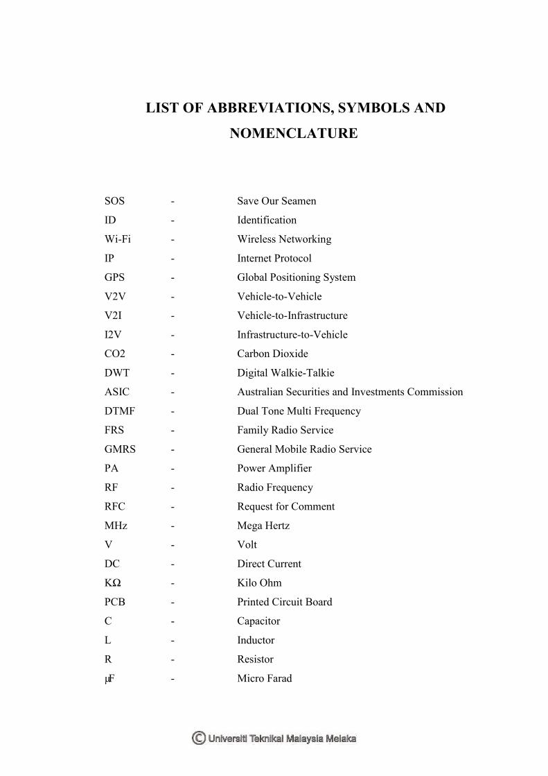
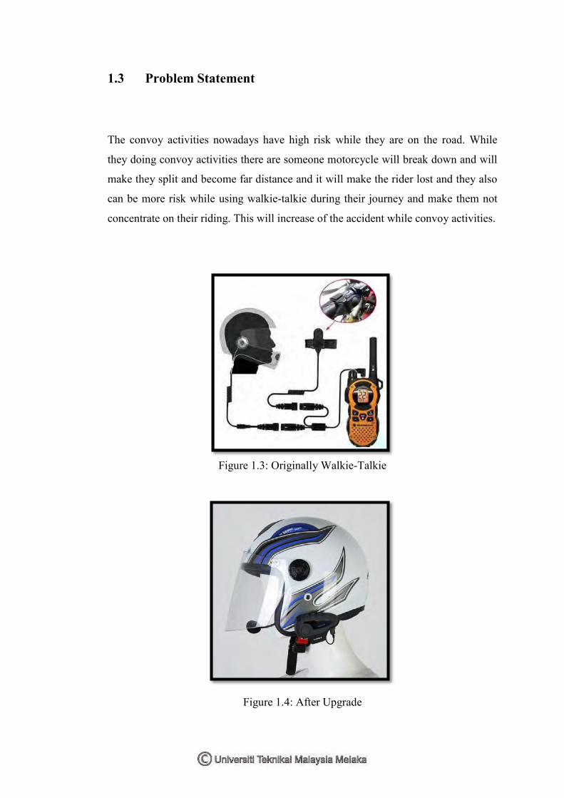
1.3 Problem Statement
The convoy activities nowadays have high risk while they are on the road. While
they doing convoy activities there are someone motorcycle will break down and will
make they split and become far distance and it will make the rider lost and they also
can be more risk while using walkie-talkie during their journey and make them not
concentrate on their riding. This will increase of the accident while convoy activities.
Figure 1.3: Originally Walkie-Talkie
Figure 1.4: After Upgrade

5
1.4 Objective
In this project, an improvement for the Bikers Communication Device will be
implementing. The objective is very important because the achievement of the
objective in completing this report. In order to make this project were successfully it
must follow the objective that has been targeted. The core objective which has been
designated as fundamental to the project is:
a) To study how far that range can be used between receiver and transmitter
b) To develop the Bikers Communication Device that can be install at the
helmet and easy to use.
c) To implement the new device that can avoid many accidents during
motorcycle convoy activities.
1.5 Work Scope
The main scope of this project is to communicate between the riders during
motorcycle convoy activities by using the device same as walkie-talkie that was
install at the helmet. This biker communication device will be used as a prototype
and it will set to operates for a few actions such transmit and receive the command
between two people. This device will set for only one channel to make sure it easy to
use and can avoid from overlapping the frequency during communicate. Another
scope is this device will make the riders easy to use and no need to hold the walkie-
talkie because it will make the rider not concentrate while there are riding. These
project use transceiver circuits which mean it contains both circuits which are
transmitter and receiver. The distance of the signal depends on the power that
supplied on it and the signal strength (dBm) and also the power for the circuit.
6
1.6 Project Significant
This biker communication device is using the transmitter and the receiver circuit but
it already being upgrade to make sure it give the benefit to the rider and can reduce
the accident while convoy activities. By using this device, the rider does not need to
hold first and need to press the button when want start to talk. By using this biker
communication device the rider or the user just install at the helmet and feel free
when it no needs to hold this device. So that, both hand of the rider can grip fully at
the handle just need push the button when want start to talk.
1.7 Report Organization
In this part, it will explain the process and the flow for completing this report and
project. This report will be having a few chapters and it will be explain each of the
part as below:
Chapter 1: Introduction
In this chapter it will simply briefing what is the project to be. For this part, it
contains introduction, problem statement, objective, work scope, project significant
and what have included in this report.
Chapter 2: Literature Review
This chapter explains about the research of our project and also it is the previous
project that can make as references.

7
Chapter 3: Methodology
In this part, it will show the method that we use for making this project. The entire
step from the beginning to produce this device will include in this part.
Chapter 4: Result Expectation
For this part, it will state what the project look like and what the result will be obtain
when the project already done, is it the product can achieve the target.
Chapter 5: Conclusion
Lastly, this chapter will summarize the entire project that already done and also the
major conclusion of this project to discuss that is it the project achieve the entire
objective.

8
While making this project, there are some studied and research had been done to
complete this report. The information was gained by many sources such as books,
articles, journals, and internet. All the information that been collected is very useful
as a guide in doing this project. The collecting data is based on the past related study.
2.1 Introduction
In this chapter will describe the literature review, which related to the Biker
Communication Device that will be uses during convoy activity by using receiver
and the transmitter. The literature review is important which because we can learn
new thing before the previous project and we also can implement the new project
base on old project that will make it suitable and more easy to use. The reference
from previous project will make we get more knowledge about what we want to do.
Nowadays, many type of walkie-talkie at the market, as we know the many brands
that produce the walkie-talkie but how many brand that provide the simple walkie-
talkie that easy to use with two channel which is one for transmit and one for receive.
There also, we can learn the movement of the frequency from it transmit and when it
receives. Currently, most walkie-talkie use receiver and the transmitter as the
medium sent data and the different is between the range that can walkie-talkie
support and the channel that provide in walkie-talkie. Unfortunately, walkie-talkie is
less secure due to its limitation range and the way to use it. Thus, by implement and
develop Biker Communication Device it will overcome this entire problem.
LITERATURE REVIEW
CHAPTER 2

9
2.2 Application of Walkie-Talkie
There are many walkie-talkies nowadays at the market and there also has much
different function compare to each other. By this project, we will use more simple
way to develop and implement new walkie-talkie to make it safe to use and easy to
handle. This project will name it as Biker Communication Device that only uses one
channel of transmission frequency to transmit and receive the data.
The development of this device will make user friendly with it and more safety while
use it. This device also use the receiver and transmitter but we change the using of
frequency by using one channel only and the device will install direct to the helmet.
There is some research from the previous project that are using walkie-talkie and
implement from it.
2.3 Walkie-Talkie Application upon Android Device
How to handle this Save Our Seamen (SOS) communication in these emergent
circumstances are very critical. The solution to address all these needs is wireless
direct communication of Walkie-Talkie in this report. This direct communication of
Walkie-Talkie allows two or more peers to talk to other ones directly by using
mobile devices. In order to meet all those needs requiring Walkie-Talkie we designed
and specified some goals or principles to design the wireless direct communication
framework. First of all, this direct mobile communication does not rely on access
point. Second of all, this direct mobile communication is wireless. Third of all, this
direct mobile communication is low latency, meaning that the talk is responded very
quickly. Fourth of all, this direct mobile communication is high bandwidth, meaning
that there is no congestion and audio is very smooth. We summarized these design
goals or principles to be ad-hoc, wireless and real-time. To implement these design
principles we choose to implement our walkie-talkie in android mobile devices on
top of Wi-Fi-Direct. (Professor Bhaskar Krishnamachari, 2012)


