
UNIVERSITI PUTRA MALAYSIA
NOR HIDAYAH BINTI DAUD
FK 2015 177
MINIATURIZATION OF UHF RFID TAG ANTENNA

© COPYRIG
HT UPM
MINIATURIZATION OF UHF RFID TAG ANTENNA
By
NOR HIDAYAH BINTI DAUD
Thesis Submitted to the School of Graduate Studies, Universiti Putra
Malaysia, in Fulfilment of the Requirements for the Degree of Master of
Science
January 2015

© COPYRIG
HT UPM
COPYRIGHT
All material contained within the thesis, including without limitation
text, logos, icons, photographs and all other artwork, is copyright
material of Universiti Putra Malaysia unless otherwise stated. Use may
be made of any material contained within the thesis for non-commercial
purposes from the copyright holder. Commercial use of material may
only be made with the express, prior, written permission of Universiti
Putra Malaysia.
Copyright © Universiti Putra Malaysia

© COPYRIG
HT UPM
i
Abstract of thesis presented to the Senate of Universiti Putra Malaysia in fulfillment of
the requirement for the degree of Master of Science
MINIATURIZATION OF UHF RFID TAG ANTENNA
By
NOR HIDAYAH BINTI DAUD
January 2015
Chair: Assoc. Prof. Alyani Binti Ismail, PhD
Faculty: Engineering
The main aim of this research is to reduce the size of RFID tag antenna using several
miniaturization techniques. The tag antenna comprises of meandered lines and
capacitive – tip loading integrated with two square split – ring resonators (S – SRRs). It
was simulated using 3D full – wave electromagnetic simulator (CST Microwave Studio
2013) on FR4 epoxy substrate with the dielectric constant of 4.4, the loss tangent of
0.02 and the thickness of 1.53 mm. The UHF RFID chip used in this design was
MURATA RFID Magicstrap LXMS31ACNA-010 chip with the impedance of 12 –
j106.3 Ω at 921 MHz. The antenna has been designed to cover the frequency range in Malaysia, 919 MHz to 923 MHz. A parametric study of the proposed tag antenna was
carried out in order to optimize the main effected parameters. The performance of the
proposed tag were analysed in terms of return loss, antenna gain and maximum
readable range. As compared to other passive UHF RFID tag antenna it is found that
the size of antenna has achieved 61% reduction in size. It occupies the volume of 48 ×
22 × 1.53 mm3. The measured read range of the proposed tag antenna is 4.60 m. Details
of the proposed tag antenna design and measurement results are presented and
discussed.

© COPYRIG
HT UPM
ii
Abstrak tesis yang dikemukakan kepada Senat Universiti Putra Malaysia sebagai
memenuhi keperluan untuk ijazah Sarjana Sains
PENGECILAN UHF RFID ANTENA LABEL
Oleh
NOR HIDAYAH BINTI DAUD
Januari 2015
Pengerusi: Prof. Madya Alyani Binti Ismail, PhD
Fakulti: Kejuruteraan
Tujuan utama penyelidikan ini dilakukan adalah mengenai proses pengurangan saiz
antena label menggunakan beberapa teknik pengecilan. Antena label yang dicadangkan
mengandungi dipol yang mempunyai garis lenturan dan kemuatan hujung yang
berintegrasi dengan dua struktur square split – ring resonators (S – SRRs). Ia
disimulasi menggunakan 3D full – wave electromagnetic simulator (CST Microwave
Studio 2013) di atas substratum epoksi FR4 dengan pemalar dielektrik bernilai 4.4,
kehilangan tangent sebanyak 0.02 dan ketebalan bernilai 1.53 mm. UHF RFID cip yang
digunakan di dalam rekabentuk ini adalah cip MURATA RFID Magicstrap LXMS31ACNA-010 dengan galangan 12 – j106.3 Ω pada 921 MHz. Antena label yang
dicadangkan di rekabentuk meliputi keseluruhan julat frekuensi di Malaysia, 919 MHz
kepada 923 MHz. Kajian parametric kepada antena yang dicadangkan telah di bawa
bersama dalam mengoptimis kesan parameter yang utama. Prestasi terhadap antena
yang dicadangkan dianalisis dari segi return loss, gandaan antenna dan julat bacaan
yang maksimum. Jika dibandingkan dengan UHF RFID antena label yang lain, didapati
bahawa saiz antena yang dicadangkan telah mecapai kadar pengurangan saiz sebanyak
61%. Ia mencapai isipadu 48 × 22 × 1.53 mm3. Pengukuran bacaan julat kepada antena
yang dicadangkan ialah 4.60 m. Lanjut mengenai rekabentuk antena yang dicadangkan
dikaji secara terperinci dan keputusan pengukuran dibentangkan dan dibincang.

© COPYRIG
HT UPM
iii
ACKNOWLEDGEMENTS
In the name of Allah, the Beneficent, the Merciful. May Allah‘s peace and blessing be
upon our Beloved Prophet Muhammad who was a mercy unto us from Allah S.W.T.,
who character and notability none has seen before or after Him (S.A.W.). All praise is due to Allah S.W.T. for giving me a chance in completing my Master degree in
Universiti Putra Malaysia.
This report could not have been written without the help of a number of people. They
have contributed towards my understanding and thoughts. In particular, I would like to
take this opportunity to gives special thanks to my beloved parents for being supportive
persons to me in finishing my research. Your prayer for me was what sustained me thus
far. I also appreciate my brothers and my beloved sister for their love, prayers and
invaluable assistance provided throughout my research studies. Words cannot express
how grateful I am.
I would like to thank to my main research supervisor, Associate Professor Dr. Alyani
Ismail for her tireless effort, helpful discussion, guidance, critics and supportive
comments. Without her continued support and interest, this thesis would not have been
the same as presented here. I would like to express my profound gratitude and deep
regards to my committee members, Associate Professor Dr. Aduwati Sali and Associate
Professor Dr. Mohd Fadlee A. Rasid for their full support and guidance. Thanks for
reviewing my Master work.
Finally, I would like to express sincere appreciation to my fellow friends in Wireless
Laboratory (Level 4) for their help, friendship, encouragement and love. The help and
support for all people as presented above are acknowledged gratefully. May Allah
S.W.T. make all our intentions sincere for His pleasure alone Amin.

© COPYRIG
HT UPM
iv
I certify that a Thesis Examination Committee has met on 30 January 2015 to conduct
the final examination of Nor Hidayah binti Daud on her thesis entitled ―Miniaturization
of UHF RFID Tag Antenna‖ in accordance with the Universities and University
Colleges Act 1971 and the Constitution of the Universiti Putra Malaysia [P.U.(A) 106]
15 March 1998. The Committee recommends that the student be awarded the Master of
Science.
Members of the Thesis Examination Committee were as follows:
Shaiful Jahari Bin Hashim, PhD
Senior Lecturer
Faculty of Engineering
Universiti Putra Malaysia
(Chairman)
Roslina Binti Mohd Sidek, PhD
Associate Professor Faculty of Engineering
Universiti Putra Malaysia
(Internal Examiner)
Sharul Kamal Bin Abdul Rahim, PhD
Professor Ir.
Faculty of Electrical Engineering
Universiti Teknologi Malaysia
Malaysia
(External Examiner)
ZULKARNAIN ZAINAL, PhD
Professor and Deputy Dean
School of Graduate Studies
Universiti Putra Malaysia
Date: 13 May 2015

© COPYRIG
HT UPM
v
This thesis was submitted to the Senate of Universiti Putra Malaysia and has been
accepted as fulfilment of the requirement for the degree of Master of Science. The
members of the Supervisory Committee were as follows:
Alyani Binti Ismail, PhD Associate Professor
Faculty of Engineering
Universiti Putra Malaysia
(Chairman)
Aduwati Binti Sali, PhD
Associate Professor
Faculty of Engineering
Universiti Putra Malaysia
(Member)
Mohd Fadlee Bin A. Rasid, PhD
Associate Professor
Faculty of Engineering
Universiti Putra Malaysia
(Member)
BUJANG BIN KIM HUAT, PhD
Professor and Dean
School of Graduate Studies
Universiti Putra Malaysia
Date:

© COPYRIG
HT UPM
vi
Declaration by graduate student
I hereby confirm that:
this thesis is my original work;
quotations, illustrations and citations have been duly referenced;
this thesis has not been submitted previously or concurrently for any other degree
at any other institutions;
intellectual property from the thesis and copyright of thesis are fully-owned by
Universiti Putra Malaysia, as according to the Universiti Putra Malaysia (Research) Rules 2012;
written permission must be obtained from supervisor and the office of Deputy
Vice-Chancellor (Research and Innovation) before thesis is published (in the form
of written, printed or in electronic form) including books, journals, modules,
proceedings, popular writings, seminar papers, manuscripts, posters, reports,
lecture notes, learning modules or any other materials as stated in the Universiti
Putra Malaysia (Research) Rules 2012;
there is no plagiarism or data falsification/fabrication in the thesis, and scholarly
integrity is upheld as according to the Universiti Putra Malaysia (Graduate
Studies) Rules 2003 (Revision 2012-2013) and the Universiti Putra Malaysia
(Research) Rules 2012. The thesis has undergone plagiarism detection software.
Signature: ________________________ Date: __________________
Name and Matric No.: _________________________________________

© COPYRIG
HT UPM
vii
Declaration by Members of Supervisory Committee
This is to confirm that:
the research conducted and the writing of this thesis was under our supervision;
supervision responsibilities as stated in the Universiti Putra Malaysia (Graduate
Studies) Rules 2003 (Revision 2012-2013)are adhered to.
Signature:
Name of Chairman of
Supervisory
Committee:
Signature:
Name of Member of
Supervisory
Committee:
Signature:
Name of Member of
Supervisory
Committee:

© COPYRIG
HT UPM
viii
TABLE OF CONTENTS
Page
ABSTRACT i
ABSTRAK ii
ACKNOWLEDGEMENTS iii
APPROVAL v
DECLARATION vii
LIST OF TABLES x
LIST OF FIGURES xiv
LIST OF ABBREVIATIONS xv
CHAPTER
1 INTRODUCTION 1
1.1 Radio Frequency Identification (RFID) 1
1.2 Problem Statement 2
1.3 Objectives 3
1.4 Scope of Research 3
1.5 Overview of Research Methodology 4
1.6 Organization of the Thesis 5
2 LITERATURE REVIEW 6
2.1 Introduction 6
2.2 Background of RFID 6
2.3 Principles of Operation 7
2.3.1 Active RFID System 7
2.3.2 Passive RFID System 8
2.3.3 Semi – passive RFID System 8
2.4 Frequencies Operations 9
2.5 Antenna Types 10
2.6 Miniaturization Techniques 10
2.6.1 Meandering Method 12
2.6.2 Capacitive – Tip Loading Technique 12
2.6.3 Split Ring Resonators (SRRs) Structure 14
2.6.4 Inverted – F Structure 14
2.6.5 Fractal Antenna 15
2.7 Application Specific Integrated Circuit (ASIC) chips 16
2.8 Tag Antenna Requirements 16
2.8.1 Gain 16
2.8.2 Radiation Pattern 16
2.8.3 Half – power Beamwidth 17
2.8.4 Bandwidth 17
2.8.5 Polarization (Tag Orientation) 17
2.9 Material and Cost 18
2.10 Fabrication Process 19
2.11 Impedance Measurement on the UHF RFID Tag Antenna 20
2.11.1 Impedance Matching 21
2.11.2 Power Reflection Coefficient (PRC) 22
2.11.3 Smith Chart 24

© COPYRIG
HT UPM
ix
2.12 Read Range Measurement 24
2.12.1 Theoretical Read Range 25
2.12.2 Measurement Read Range 26
2.13 Current Research about the RFID 26
2.13.1 Meandered Patch Antenna 27
2.13.2 Low-Profile Meandered Patch Antennas 28
2.13.3 Meander Dipole with HIS (High Impedance
Surface) Substrate
29
2.13.4 Compact Fractal Dipole for bi-band RFID
Application
30
2.13.5 Design of Label – Typed Tag Antenna for
Metallic Object
30
2.13.6 Metal Mount Compact Microstrip RFID Tag 31
2.13.7 Meander Line Antenna (MLA) 31
2.13.8 Planar Wideband Inductively Coupled Feed
Patch Antenna
32
2.13.9 Compact Strip Dipole Coupled Split-Ring Resonator Antenna
33
2.14 Summary of Literature Review 34
2.15 Summary 34
3 METHODOLOGY 35
3.1 Introduction 36
3.2 Measurement on the Proposed Tag Antenna using Test
Fixture
37
3.2.1 Impedance Measurement 39
3.2.2 Test Fixture 41
3.3 Read Range Measurement 44
3.4 Antenna Design 47
3.5 Summary 47
4 RESULTS AND DISCUSSION 48
4.1 Introduction 48
4.2 Dipole Antenna with Meandering Technique 48
4.2.1 Design and Analysis on Different Numbers of
Bending, n
51
4.2.2 Design and Analysis on the Proposed Meander
Line Antenna
56
4.3 Dipole Antenna with Meandering and Capacitive Tip –
Loading Techniques
57
4.3.1 Simulation Results 60
4.3.2 Measurement Results using Vector Network
Analyzer (VNA)
64
4.3.3 Read Range Measurement 65
4.4 Integration of Square Split Ring Resonators (S-SRRs) to
UHF RFID Tag Antenna for Size Reduction
66
4.4.1 Simulation Results 72
4.4.2 Measurement Results 75
4.4.3 Read Range Measurement 76
4.5 Summary 78

© COPYRIG
HT UPM
x
5 CONCLUSIONS, CONTRIBUTIONS AND
RECOMMENDATIONS FOR FUTURE WORK
79
5.1 Conclusions 79
5.2 Contributions 80
5.3 Recommendations for Future Works 80
REFERENCES 89
APPENDICES 91
BIODATA OF STUDENT 92
LIST OF PUBLICATIONS 93

© COPYRIG
HT UPM
xi
LIST OF TABLES
Table
Page
2.1 RFID operating frequencies 9
2.3 Summary of previously reported designed on RFID tag antenna 34 4.1 Antenna parameters for n = 1 49
4.2 Antenna parameters for n = 2 50
4.3 Antenna parameters for n = 3 50
4.4 Antenna dimensions 52
4.5 Dimensions of meandered dipole tag antenna 57
4.6 Simulated and measured on half – power bandwidth of the tag
antenna
62
4.7 Measured gain (dBi) of the tag antenna 65
4.8 Dimensions of meandered dipole tag antenna 66
4.9 Simulated and measured on half – power bandwidth of the tag
antenna
74
4.10 Measured gain (dBi) of the tag antenna 76
4.11 Comparison between the proposed tag and previously reported
designed
78

© COPYRIG
HT UPM
xii
LIST OF FIGURES
Figure
Page
1.1 Flow Chart of the Design Process UHF RFID Tag Antenna 4
2.1 System Components in RFID 6 2.2 RFID System Operations. The backscattered signal is modulated by
changes in chip impedance Zc
8
2.3 Half – Wavelength Dipole Antenna 10
2.4 A Meandered Antenna with Reduced Projected Length 11
2.5 Series Matched Equivalent Circuit of the Dipole Antenna 12
2.6 Various Types‘ Antenna Structure With Capacitive Tip – Loading (A)
Meander Lines With Capacitive –Tip Loading (b) Wire Antenna
Loaded With Tip- Loading (c) Resonant Dipole With Differing Line
widths (d) Bow – Tie Dipole Antenna
12
2.7 (a) Layout of Circular SRR (c) Equivalent Circuit Model of SRR 14
2.8 (a) F-shaped printed monopole antenna (b) Fabricated planar inverted – F antenna (PIFA)
14
2.9 Different fractal curves (a) Koch (b) Sierpinski, (c) ‗tree‘, (d)
‗cuboid‘, (e) ‗log-periodic‘, (f) Minkowski
15
2.10 Two-Port Measurement Jig 20
2.11 Measuring the Dipole Antenna 20
2.12 RFID Transponder Equivalent Circuit 21
2.13 Generator – Load Circuit with Two Complex Impedances 22
2.14 Smith Chart Curve 23
2.15 Complex Power Wave Reflection Coefficient 24
2.16 Antenna Impedance Chip Impedance and Range for a Typical RFID
Tag
26
2.17
(a) Array Antenna Fed by Two Quarter -Wavelength Microstrip Lines Without Matching Stubs (b) Array Antenna Fed by Two Quarter-
Wavelength Microstrip Lines with Two Matching Stubs
27
2.18 (a) Geometries of the Four Elements Proposed Meandered Patch
Antennas (b) Structure of the Fabricated Antenna Designed
28
2.19 The Structure of RFID Tag Antenna (a) Dipole-Type Antenna
Structure (b) HIS Structure (c) Cross Sectional View RFID Tag
Antenna
29
2.20 Geometry of Presented Tag (a) Top View. (b) Cross-Sectional View 30
2.21 Geometry of Presented Tag 30
2.22 Configuration of the Presented Compact Microstrip Tag Antenna 31
2.23 (a) Structure of Antenna Designed (b) Photo of Fabricated Antenna Designed
31
2.24 Antenna Geometry (a) Top View (b) Proposed Wideband Antenna 32
2.25 (a) Structure of Antenna Designed (b) Enlarged Plot of the Central
Part of Strip Dipole with Strap of the Chip Attached
33
3.1 Design Process of Proposed Tag Antenna 36
3.2 (a) Two-Port Impedance Model of an Antenna and Feed (b) Layout of
a dipole antenna and its impedances
38
3.3 (a) Test fixture without antenna under test (AUT) (b) Test fixture with
antenna under test (AUT)
39
3.4 Construction on the Measurement Setup 40

© COPYRIG
HT UPM
xiii
3.5 Flow Chart for Measuring the Tag Antenna using Test Fixture 41
3.6 Types of Installation (a) Vertical (b) Horizontal 42
3.7 (a) Vertical Installation to Measure Maximum Read Range of the
Proposed Tag Antenna (b) Reader Antenna
42
3.8 Measurement Setup to Measure Maximum Read Range of the
Proposed Tag Antenna
43
3.9 Operation Procedures for Read Range Measurement 44
3.10 Meander Lines (a) n = 1 (b) n = 2 (c) n = 3 45
3.11 Meander Lines with Capacitive – Tip Loading Method 46
3.12 Square Split –Ring Resonators Structure (S – SRRs) 47
4.1 Prototype of Meander Lines when n = 1 49
4.2 Prototype of Meander Lines when n = 2 50
4.3 Prototype of Meander Lines when n = 3 50
4.4 Simulated Results of S11 with Various Meander Lines, n 51
4.5 Structure of the Meandered Dipole Antenna with n = 2 51
4.6 Side View of Meander Line n = 2 of the Dipole Tag Antenna 51
4.7 Simulated Results of Various Parameters g0 52 4.8 Simulated Results of Various Parameters s 53
4.9 Simulated S11 (dB) of the Tag Antenna with n = 2 54
4.10 Simulated Input Impedance of the Proposed Tag Antenna in Wide
Frequency Range
54
4.11 Simulated Input Impedance of the Proposed Tag Antenna from 840
MHz to 960 MHz
55
4.12 (a) Simulated Gain. Radiation Pattern (b) H– Plane (c) E– Plane 56
4.13 Prototype Designed on the UHF RFID Tag 56
4.14 Side View of Single – Sided Meander Dipole Tag Antenna 57
4.15 Simulated Results of Various Parameters a 58
4.16 Simulated Results of Various Parameters b 58
4.17 Simulated S11 (dB) of the Tag Antenna without S – SRR structure 59 4.18 (a) Simulated Gain. Radiation Pattern (b) H– Plane (c) E– Plane 60
4.19 (a) Photograph of the Fabricated RFID Tag (b) Photograph of the
Front and Back Plane of FR4 Substrate
60
4.20 Measurement Setup on the Tag Antenna 61
4.21 Power Reflection Coefficient (PRC) for Simulated And Measured
Results
62
4.22 Simulated Impedance of Proposed Tag Antenna in a Region of
Interest
63
4.23 Power Reflection Coefficient, 𝑠 2 for Simulated and Measured Results
64
4.24 Prototype of the Meandered Dipole Antenna with Capacitive – Tip
Loading Designed
65
4.25 Prototype of the Square Split – Ring Resonators (S-SRRs) 66 4.26 Side View of Double – Sided Meander Dipole Tag Antenna 66
4.27 Simulated Results of Various Parameters s1 67
4.28 Simulated Results of Various Parameters gd 68
4.29 Simulated Results of Various Parameters gw 68
4.30 Simulated Results of Various Parameters gi 69
4.31 Simulated Results of Various Parameters gs 69
4.32 Simulated Results of S11 with and without SRR Structure 70
4.33 Simulated S11 (dB) of the Tag Antenna with S – SRR structure 71
4.34 (a) Simulated Gain. Radiation Pattern (b) H – Plane (c) E – Plane 71

© COPYRIG
HT UPM
xiv
4.35 Radiation Pattern of Proposed Tag Antenna with and without Loading
of SRR Structure (a) H – Plane (b) E– Plane
72
4.36 (a) Fabricated tag antenna (b) Top and bottom layer of fabricated tag
antenna
72
4.37 Measurement Setup on the Tag Antenna 73
4.38 Power Reflection Coefficient (PRC) for Simulated and Measured Results
74
4.39 Simulated and Measured Results of the Impedance (Ω) 75
4.40 Power Reflection Coefficient, 𝑠 2 for Simulated and Measured Results
75

© COPYRIG
HT UPM
xv
LIST OF ABBREVIATIONS
ASIC Application Specific Integrated Circuit
AUT Antenna Under Test
CST Computer Simulation Technology
FR4 Flame Retardant 4
EAS Electronic Article Surveillance
EPC Electronic Product Code
EIRP Effective Isotropic Radiated Power ETSI European Telecommunications Standards Institute
FCC Federal Communications Commission
GHz Gigahertz
HF High Frequency
HPBW Half-Power Beamwidths
IC Integrated Circuit
ISM Industrial-Scientific-Medical
ISO International Organization for Standardization
LCP Liquid Crystal Polymer
LOS Line – of – sight
LF Low Frequency
LH Left – Handed MCMC Malaysian Communications and Multimedia
Commission
MHz Megahertz
MLA Meander Line Antenna
MTMs Metamaterials
PCB Printed Circuit Board
PET Polyethylene terephthalate
PRC Power Reflection Coefficient
PTFE Polytetrafluoroethylene
RF Radio Frequency
RFID Radio Frequency Identification SHF Super High Frequency
SMA SubMiniature version A
SRD Short Range Devices
SRR Split-Ring Resonators
UHF Ultra High Frequency
UPC Universal Product Code
UV Ultra Violet
VNA Vector Network Analyzer

© COPYRIG
HT UPM

© COPYRIG
HT UPM
1
CHAPTER 1
INTRODUCTION
1.1 Radio Frequency Identification (RFID)
Radio frequency identification, or simply known as RFID, is a method of automatic
identification. The continuous research on RFID grows rapidly in recent years. The era
of RFID technology has been explored as direct consequences from the radio and radar
development. The United Kingdom has applied the RFID during the Second World
War to differentiate between the English and German airplane. In 1980, the RFID
technology entered the new phase in the improvement of tracking system and
exploration of application in manufacturing and other environments. The RFID was
applied by the United States in electronic toll collection technology. This is occurred in the year 1991, in the Oklahoma City, where the world‘s first highway electronic tolling
system was opened. Nowadays, RFID system is widely used in different area like
security system, animal tracking, chain management and many more (Uddin et al.,
2009; Want, 2006; Sanjay et al., 2003; Landt, 2001).
Tag antenna should also be low cost, small in size, have good impedance matching and
insensitive to the attached objects to keep performance consistent. Meanwhile, omni
directionality of the tag antenna is preferred to ensure the identification ideally radiate
from all directions (Curty et al., 2007). There are several techniques to reduce the
dimensions of conventional antennas. Meandering, folding, and bending are techniques
for antenna miniaturization, are widely used in the literature (Tirado-Mendez et al,
2013).
However, the application of RFID tag antenna using square split – ring resonators (S –
SRRs) was found to be another alternative to the miniaturization technique (Bazrkar,
2012; Ferdous et al., 2012; Booket, 2011; Dacuna and Pous, 2007). The process of
miniaturization of RFID tag was commonly conducted using parametric studies and
optimization of main effected parameters. Thus, further studies to reduce the physical
size of the radiating elements in wire antennas using effective techniques are needed to
be explored for the miniaturization of tag antenna.
1.2 Problem Statement
Performances of an RFID tag depend on the properties of the antenna. The tag antenna
must fulfill the requirements such as the antenna must be robust, longer read range, low
cost and small enough to be attached to the required object. In addition to that, the tag
antenna should be in omnidirectional and provide a maximum possible signal to the
application specific integrated circuit (ASIC) (Aivazis et al., 2011; Koski et al., 2011;
Laran RFID, 2004; Qing and Yang, 2004; Foster and Burberry, 1999).
To enhance the performance characteristics of the tag antenna, researchers have
modified the conventional dipole structure using numerous techniques. Several

© COPYRIG
HT UPM
2
approaches have been done in an attempt to reduce the tag size. Some articles have
sought achieving improved gains and small size by using different configurations of
miniaturization method. Existing literatures provide several techniques for reducing the
tag size (Mehrparvar et al., 2012; Hu et al., 2011; Kim et al., 2010; Wu et al., 2010).
The most common method used by the researchers to reduce the tag antenna is by
meandering method. Even though the meandering method showed its capability in reduction size of antenna, there were some disadvantages related to it. It produced low
radiation efficiency, narrow bandwidth and not capable to operate at multiband
frequencies (Faudzi et al., 2013a; Faudzi et al., 2013b; Jahanbakshi et al., 2012; Hu et
al., 2011; Dobkin, 2008). The used of capacitive tip loading provide a satisfactory
reduction in size and contribute in improving the gain. It can be done through formation
of a large structure at the end of the dipole antenna (Faudzi et al., 2013a; Faudzi et al.,
2013b; Hu et al., 2011; Ghiotto et al., 2010; Im et al., 2009; Dobkin, 2008). However,
the capacitive tip loading does not contribute in improving the gain significantly due to
size limitations.
Besides, the use of fractal geometries is also capable in reducing the size of RFID tag (Aivazis et al., 2012 and Manjibhai et al., 2012). Their applicability to RFID tags is
good promising, even though the theory behind fractal antennas is quite complex. The
geometries of fractal shapes were generated in iterative patterns. Nevertheless, the
fractal antennas have several drawbacks which include loss in gain, very complex and
degrade the antenna parameters after a few iterations. Another method to reduce the tag
size is using the planar inverted – F antenna (PIFA). It has a high gain but the size of
the antenna becomes large due to the additional ground plane (Kim et al., 2011; Kim
and Choi, 2010; Chen et al. 2010a; Uddin et al., 2009; Marroco, 2008).
In Malaysia, RFID industry had grown since year 2005. The operating frequency for
Radio Frequency Identification (RFID) has a range which varies from 919 MHz – 923
MHz. The permissible frequency allocation in Malaysia has been controlled by the Malaysian Communications and Multimedia Commission (MCMC) (Minan, 2007).
Nowadays, there are a lot of works done in miniaturizing the RFID tag antenna based
on operating frequency in Malaysia (Faudzi et al., 2013a and Tan & Ismail, 2012).
However, there are still some performances need to be improved, such as the size of
tag, gain, and read range performance which based on the several miniaturization
techniques. Both of their studies utilize CST Microwave Studio for simulation process.
As a result, it is important to find out the suitable miniaturization method to reduce the
size of tag antenna.
1.3 Objectives
This research aims to study a compact RFID tag antenna. The specific objectives are as
below:
1. To identify the suitable antenna design and investigate the potential of
integrating several miniaturization techniques as a method to reduce the
size of RFID tag.
2. To analyze parametric effect of the designed antenna such as size of tag,
gain, radiation pattern, and matching impedance.

© COPYRIG
HT UPM
3
3. To investigate the effectiveness of the designed tag in terms of reading
range measurement.
1.4 Scope of Research
This study was conducted within its scopes. The scopes of this study were listed below:
The meandered dipole antenna integrating with square split – ring resonators
(S- SRRs) and capacitive – tip loading was utilized.
The tag performance was assessed in term of size, gain, radiation pattern,
matching impedance and read range measurement. These parameters were
common parameters measured, as indicators to assess the tag performance.
A UHF RFID reader (Model: UHF – RW – G2 – 232) was chosen as an
equipment for measuring read range performance. The performance of
maximum read range was assessed through the comparison of the result obtained from the calculated part with those obtained by the measurement
reader.
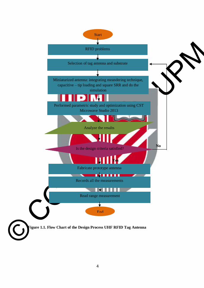
1.5 Overview of Research Methodology
The first step in the methodology consists of the studies about the challenges and the
potential research in designing the RFID tag antenna. The tag antenna will be designed
by modeling, simulating, and optimizing by monitoring the size of tag, antenna gain,
return loss and input impedance. Tag antenna was designed using the simulation on full – wave electromagnetic simulator (CST Microwave Studio, Version 2013). Parametric
study for an antenna is performed until the requirements are met. If the design
requirements are satisfied, the antenna design is ready. Otherwise, the design is further
modified and optimized until requirements are met. Once the RFID problems were
initialized, RFID requirements can be translated into the selection of antenna type and
its parameter. Then, the proposed tag antenna can be fabricated after optimization.
Finally, measurement can be implemented on the proposed tag antenna to validate the
design methods. The developed methodology for designing RFID tag antenna is
illustrated in a flow chart as shown in Figure 1.1.
© COPYRIG
HT UPM
4
Figure 1.1. Flow Chart of the Design Process UHF RFID Tag Antenna
Start
RFID problems
Selection of tag antenna and substrate
Performed parametric study and optimization using CST
Microwave Studio 2013
Analyze the results
Is the design criteria satisfied?
Records all the measurements
Fabricate prototype antenna
Read range measurement
No
Yes
Miniaturized antenna: integrating meandering technique,
capacitive – tip loading and square SRR and do the
simulation
End

© COPYRIG
HT UPM
5
1.6 Organization of Thesis
This thesis consists of five chapters. It was organized as follows.
Chapter 1 presented an introductory part for the overview of the history and the current scenario of RFID tags in Malaysia. This introductory part also provided the basic
discussion of the problem associated with the design of RFID tag antenna. Problem
statements, objectives and scope of the study also outlined in this chapter.
Meanwhile, Chapter 2 presents a detailed description on the literature reviews which
based on the RFID Technology. It includes the components of the RFID system, the
regulations in RFID which covers the operating frequency. This part reviews all the
work done found from the various publications by the previous researchers. The details
explanations about the fabrication process in producing RFID tag antenna, power
reflection coefficient analysis, input impedance and the maximum read range
In Chapter 3, the experimental methodology involved in this study is explained and
interpreted in the form of a flowchart. Chapter 4 presents the results obtained from the
experimental work, in the form of graphs and tables that included the detailed
explanation. Last but not least, the conclusion of the study and some recommendations
for future work are provided in Chapter 5.

© COPYRIG
HT UPM
81
REFERENCES
Abo-Elnaga, T. G., E. A. Abdallah, and H. M. El-Hennawy (2011). Analysis And
Design Of Universal Compact Flexible UHF RFID Tag Antenna Progress In
Electromagnetics Research B, Vol. 35, 213 – 239.
Aivazis, E., Siakavara, K., and Sahalos, J., N., (2012). Design and Analysis of Efficient
Fractal Antennas for UHF RFID Passive Tags. 6th European Conference on
Antennas and Propagation (EUCAP), 3021 – 3025.
Alimenti F., Orecchini G., Virili M,, Palazzari V., Mezzanotte P., Roselli L. (2011).
Design of Paper – Substrate Dipole Antennas Magnetically Coupled to UHF RFID
Silicon Chips. IEEE International Conference on RFID – Technologies and
Applications,219 – 222.
Amin, Y. (2013). Printable Green RFID Antennas for Embedded Sensors, PhD Thesis,
KTH School of Information and Communication Technology, Stockholm, Sweeden.
Bakore, R., West, J.C., Hutchens, C. and Ahmed, R. (2013).Design of a Proposed
Folded Dipole Antenna for use with an Implantable RFID Tag at 915 MHz, IEEE
Antennas and Propagation Society International Symposium (APSURSI), 2085 –
2086.
Balanis C. A. (2005). Antenna Theory: Analysis and Design, Third Edition, New York:
John Wiley & Sons, Inc.
Bashri, M.S.R., Ibrahimy, M. I., and Motakabber, S.M.A. (2013). A Planar Wideband
Inductively Coupled Feed Patch Antenna for UHF RFID Tag. IEEE International
Conference on RFID – Technologies and Applications (RFID – TA), 1 – 6.
Bazrkar, A., Gudarzi, A., Mahzoon, M. (2012).Miniaturization of Rectangular Patch
Antennas Partially Loaded With μ-Negative Metamaterials, International
Conference on Electronics, Biomedical Engineering and its Applications
(ICEBEA'2012), 289 – 292.
Bjorninen, T. Babar, A. A., Ukkonen, L., Sydanheimo, L. Elsherbeni, A. Z. and
Kallioinen, J.(2012). Compact Metal Mountable UHF RFID Tag on a Barium
Titanate Based Substrate. Progress in Electromagnetics Research C, Vol. 26, 43 –57,
43 – 57.
Booket, M. R., Jafargholi, A., Atlasbaf, Z. and Kamyab, M. (2011). Miniaturized Dual-
band Dipole Antenna Loaded with Metamaterial Based Structure,19th IEEE Iranian
Conference on Electrical Engineering,1 – 4.
Chen, H. D. and Tsao, Y. H. (2010a). Low – Profile PIFA Array Antennas for UHF
Band RFID Tags Mountable On Metallic Objects,‖ IEEE Trans. Antennas and
Propagation, Vol. 58, No. 4, 1087 – 1092.
Chen, H.-D.and Y.-H. Tsao, (2010b). Low-profile meandered patch antennas for RFID
tags mountable on metallic objects. IEEE Antennas Wireless Propag. Lett., Vol. 9,
No. 1, 118 – 121.

© COPYRIG
HT UPM
82
Choi, W., Seong, N., Kim, J. M., Pyo, C., Chae, J. (2005). A Planar Inverted – F
Antenna (PIFA) to be attached to Metal Containers for an Active RFID Tag. IEEE,
Antennas And Propagation Society International Symposium, 1B, 508 – 511.
Choi, W. Son, H. W., Shin, C. Bae, J.-H.and Choi, G. (2006). RFID tag antenna with a meandered dipole and inductively coupled feed. IEEE Antennas and Propagation
Society International Symposium 2006, 619 – 622.
Choo, J., Ryoo, J., Hong, J., Joen, H., Choi, C.and Tentzeris, M. M. (2009). T-
Matching Networks for the Efficient Matching of Practical RFID Tags, European
Microwave Conference, City, ST//Country 2009, 5-8.
Cisco (2007).Antenna Patterns and Their Meaning. Cisco System Inc., White Paper,
Online available at:
http://www.cisco.com/c/en/us/products/collateral/wireless/aironet-antennas-
accessories/prod_white_paper0900aecd806a1a3e.html, (accessed 7/4/2014).
Computer Simulation Technology (CST) Microwave Studio (2013), Version 2013.
Coonrod, J. (2011). Understanding When To Use FR-4 or High Frequency Laminates
Rogers Corporation Advanced Circuit Materials Division, 26 – 30.
Comisso, M. (2007).Theoretical and Numerical Analysis of the Resonant Behaviour of
the Minkowski Fractal Dipole Antenna, IET Microw. Antennas Propag., 3 (3), 456–
464.
Curty J. P., Declerdq M., Dehollain C. & Joehl N., (2007). Design and Optimization of
Passive UHF RFID Systems, Springer, ISBN: 0-387-35274-0, New Jersey.
Dacuna, J. and Pous, R. (2007). Miniturized UHF Tags Based on Metamaterials
Geometries, Building Radio Frequency Identification for the Global Environment,
online availbale: www.bridge-project.eu.
Deleruyelle, T., Pannier P., Eagels M., and Bergeret E. (2010).An RFID Tag Antenna
Tolerant to Mounting on Materials. IEEE Antennas and Propagation Magazines, 52
(4), 14 – 19.
Dobkin, D. M., (2008). The RF in RFID: Passive UHF RFID in Practice, America,
Elsevier/ Newness, 2008.
Donghai Yu, Yao Ma, and Zhiyun Zhang. (2009), UHF Band Tag Antenna Design in
RFID System, Microwave Conference, APMC 2009, Asia Pacific, 512-515.
Faudzi, N.M., Ali, M.T., Ismail, I., Ya'acob, N., Jumaat, H. and Sukaimi, N.H.M
(2013a).UHF – RIFD Tag Antenna with Miniaturization Techniques. 10th
International Conference on Electrical Engineering/ Electronics, Computer,
Telecommunications and Information Technology (ECTI-CON), 1-5.

© COPYRIG
HT UPM
83
Faudzi, N.M., Ali, M.T., Ismail, I., Ya'acob, N., Jumaat, H. and Sukaimi, N.H.M
(2013b).A Compact Dipole UHF – RFID Tag Antenna. IEEE International RF and
Microwave Conference (RFM2013), 314 – 317.
Ferdous, S., Hossain, A., Chowdhury, H. S. M., Mahdy, M. R. C. and Abdul, M.
(2013). IET Microwave Antennas and Propagation, 7(9), 768 – 775.
Finkenzeller, K. (2010). RFID Handbook: Fundamentals and Applications in
Contactless Smart Cards and Identification, New York, John Wiley & Sons Ltd.
Foster, P.R. and Burberry, R.A. (1999). Antenna Problems in RFID Systems, IEE
Colloquium on RFID Technology. Vol.3, 1-5.
Ghiotto, A., Vuong, T. P., and Wu, K. (2010).Novel Design Stategy for Passive UHF
RFID Tags. 14th International Symposium on Antenna Technology and Applied
Electromagnetics [ANTEM] and the American Electromagnetics Conference
[AMEREM], 1-4.
Guha, D. and Antar, Y. M. M. (2011). Microstrip and Printed Antenna: New Trends,
Technique and Applications, United Kingdom, John Wiley and Sons Ltd.
He, X. J., Qiu, L., Wang, J., Geng, Z. X., Wang, J. M., Gui, T. L. (2011). A Compact
Thin – Film Sensor Based on Nested Split – Ring Resonator (SRR) Metamaterials
for Microwave Applications, Journal Infrared Mili Terahz Waves, 32, 902 – 913.
He, Z. Zhan, G. and Li, Z. (2012). Research on Passive Meander – Lined Radio
Frequence Identification Tag Antenna on Ultrahigh Frequency. 5thInternational
Conference on BioMedical Engineering and Informatics (BMEI 2012), 1507 – 1510.
He, Y. and Pan, Z. (2013). Design of UHF RFID Broadband Anti-metal Tag
Antenna Applied on Surface of Metallic Objects. IEEE Wireless Communications and
Networking Conference (WCNC), 4352 – 4357.
Hu, T., Liu, C and Zhongyu (2011). Design Analysis of UHF Tag Antenna Structure,
Microwave Conference Proceedings (CJMW), 2011 China – Japan Joint, 1 – 4.
Hung, A. W. S. and Widad, I. (2006) RFID Transponder Using Bow Tie Antenna for
Wireless Application, International RF and Microwave Conference Proceedings, 21
– 26.
Hung, C.-C., Peng, C.-M and Chen, I-F.(2013). Printed Modified Bow-Tie Dipole
Antenna for DVB/WLAN.Applications.International Journal of Antennas and
Propagation, Volume 2013, 6 pages, http://dx.doi.org/10.1155/2013/149296.
Im, Y. T., Kim, J. H., and Park W., S. (2009).Matching Techniques for Miniturized
UHF RFID Loop Antennas. IEEE Antennas and Wireless Propagation Letters, 8,
266 – 270.
Inam, M. Y. I. M. (2011). Analysis of Design Optimization of Bandwidth and Loss
Performance of Reflectarray Antennas Based on Material Properties," vol. 4: CCSE,
Modern Applied Science, 1 - 8.

© COPYRIG
HT UPM
84
Jahanbakshi, A., Moradi, Gh., and Shirazi, R. S. (2012). Design and Simulation of
Different Types of Meander Lines Antennas with Improved Efficieny. Progress in
Electromagnetics Research Symposium Proceedings, 594 – 597.
Joshi, J. G., Pattnaik, S. S., Devi, S. and Lohokare, M. R. (2013).Electrically Small Patch Antenna Loaded with Metamaterial, IETE Journal of Research, 56(6), 373 –
379.
Joshi, J.G., Pattnaik, S. S., Devi, S. and Lohokare, M.R. (2011). Bandwidth
enhancement and size reduction of microstrip patch antenna by magnetoinductive
waveguide loading, Journal of Wireless Engineering and Technology, vol.2, no.2,
37 – 44.
Kim T., Kim U. and Choi J. (2011).Design of a Compact UHF RFID Tag Antenna
using an Inductively Coupled Parasitic Element, Microwave and Technology
Letters, 53 (2), 239 – 242.
Kim U. and Choi J. (2010). Design of a Compact Wideband UHF RFID Tag Antenna,
Proceedings of Asia – Pacific Microwave Conference 2010, 987 – 990.
Kimouche, H. and Zemmour, H. (2011).A Compact Fractal Dipole Antenna for
915MHz and 2.4GHz RFID Tag Applications.Progress in Electromagnetics
Research Letters, Vol. 26, 105 – 114.
Kin, S. L., Mun, L. N. and Cole, P. H. (2007). Investigation of RF cable effect on RFID
tag antenna impedance measurement, in Proc. IEEE Ant. & Prop. Sym., 573-576.
Konya, S., T. Sasamori., T. Tobana, and Y. Isota (2012).Wideband measurement for input impedance of balanced antenna using the S-parameter method. 15th
International Symposium on Antenna Technology and Applied Electromagnetics
(ANTEM), 1 – 4.
Koo, T.-W.,Kim,D., Ryu, J.-I., Seo, H.-M., Yook, J.-G., and Kim, J.-C.(2011).Design
of a Label-Typed UHF RFID Tag Antenna for Metallic Objects. IEEE Antennas
and Wireless Propagation Letters, Vol. 10, 1010 – 1014.
Koski, K., Koski, E.,Virtanen, J., Björninen, T., Sydänheimo, L., Ukkonen, L. and
Elsherbeni, A. Z. (2012). Inkjet-Printed passive UHF RFID tags: review and
performance evaluation, International Journal of Advanced Manufacturing Technology, 62 (1-4), 167-182.
Kumar, A. Parkash, D. and Kartikeyan, M. V. (2010).Planar Antennas for Passive UHF
RFID Tag.Progress in Electromagnetics Research B, Vol. 19, 305 – 327.
Kuo, S.-K., S. -L. Chen, and C. –T. Lin (2008). An accurate method for impedance
Measurement of RFID tag antenna. Progress in Electromagnetics Research, PIER
83, 93 – 106.
Kurokawa, K. (1965). Power waves and the scattering matrix.IEEE Trans. Microw.
Theory Tech., 13(3), 194 – 202.

© COPYRIG
HT UPM
85
Landt, J. (2001). Shrouds of Time: The History of RFID. AIM Inc., White Paper,
Online available at: https://ewhdbks.mugu.navy.mil/iff.htm, (accessed 9/12/2013).
Laran RFID, (2004). A Basic Introduction to RFID Technology and its uses in the
Supply Chain, http://www.idii.com/wp/LaranRFID.pdf, January 2004, available: 01-05-2004.
Leow, C.L., Soh, P.J., Carpenter, S., Azremi, A.A.H. and Ezanuddin, A.A.M. (2008).
Design of Split Ring Resonator Filters for Interference Suppression in UWB, IEEE
International RF and Microwave Conference (RFM), 467 – 471.
Lim, S.-H. Oh, Y.-C., Lim, H., Lee,Y.- S. and Myung, N.-H. (2008). Analysis and
design of a UHF RFID tag antenna with a Split Ring ResonatorProceedings of
iWAT2008, Chiba, Japan, 446 – 449.
Lin, W. and Chu, Q.-X. (2010). A Novel RFID Tag Antenna for Matching Complex Impedances on 915MHz and 2.45GHz bands, Asia – Pacific Microwave Conference
Proceedings (APMC), 2248 – 2251.
Liu, Y., Tang, X., Zhang, Z. and Huang, X. (2013).Novel Nested Split-Ring-Resonator
(SRR) for Compact Filter Application.Progress in Electromagnetics Research, 136,
765 –773.
Liu Y., Luk, K. M., Yin, H., C., (2010). A RFID Tag Metal on a Compact HIS
Substrate. Progress in Electromagnetics Research Letters, 18, 51 – 59.
Lu, Y. Y., Wei, S. C., Li, C. Y. and Huang H. C. (2011).Design of 2.45 GHz Planar
Meander Dipole Antenna.7th International Conference on Intelligent Information Hiding and Multimedia Signal Processing. 5 – 8.
Madhuri B. E. (2006). A Novel Planar Microstrip Antenna Design for UHF RFID.
Master Thesis, University of Kansas, Kansas, United State of America.
Manjibhai, D. A., Prajapati, J. C., and Barasara, D. J. (2012). An Overview of Fractal
Geometries and Antenna, International Journal of Engineering and Science, 1(2), 1
– 4.
Makimura, H., Watanabe, Y., Watanabe, K., and Igarashi, H. (2011).Evolutional
Design of Small Antennas for Passive UHF-Band RFID.IEEE Transactions on Magnetics, Vol. 47, No. 5, 1510 – 1513.
Marrocco, G. (2008). The art of UHF RFID antenna design: Impedance – matching and
size reduction techniques. IEEE Antennas Propagation Mag. 50 (1), 66 – 79.
Marqués, R., Mesa, F., Martel, J. and Medina, F. (2003) Comparative Analysis Of
Edge- And Broadside-Coupled Split Ring Resonators For Metamaterial Design—
Theory And Experiment, IEEE Trans. Antennas Propag.,51(10), 2572–2581.
Mats, L. Cain, J. T. and Mickle, M. H. (2009).The In-Situ Technique for Measuring
Input Impedance and Connection Effects of RFID Tag Antenna. IEEE Trans.
Automation Science and Engineering, 6(1), 4-8.

© COPYRIG
HT UPM
86
Mehrparvar, M. and Kashani, F. H. (2012).Microstrip Antenna Miniaturization Using
Metamaterial Structures. 20th IEEE Iranian Conference on Electrical Engineering,
(ICEE2012), 1243 – 1246.
Meng, Q. and Jin, J. (2011). Design of Low-Power Active RFID Tag in UHF Band, International Conference on Control, Automation and Systems Engineering
(CASE), 1 – 4.
Merilampi, S., Ukkonen, L., Sydänheimo, L., Ruuskanen, P., and Kivikoski, M.
(2007). Analysis of Silver Ink Bow-Tie RFID Tag Antennas Printed on Paper
Substrates. International Journal of Antennas and Propagation, vol. 2007, Article ID
90762, 9 pages, 2007. doi:10.1155/2007/90762.
Meys, R. and Janssens, F. (1998).Measuring the Impedance of Balanced Antennas by
an S-Parameter Method.IEEE Ant. and Prop. Magazine, 40(6), 62-65.
Minan, N. A. S. (2007).Industry Readiness and Policy Regarding RFID Implementation
in Malaysia.EPCglobal Malaysia EPC/RFID Conference 2007.
Murata MAGICSTRAP® Application Note (2012), Online available:
http://www.murata.co.jp/products/rfid/index.html, (access 12/1/2012).
Nikitin, P. V., K. V. S. Rao, S. F. Lam, V. Pillai, R. Martinez and H. Heinrich (2005).
Power Reflection Coefficient Analysis for Complex Impedance in RFID Tag
Design.IEEE Transactions on Microwave Theory and Techniques, 53(9), 2721 –
2725.
Nikitin, P.V. and Rao, K.V.S. (2006).Theory and Measurement of Backscattering from RFID tags. IEEE Antennas and Propagation Magazine, 48(6), 212 – 218.
Nilsson, E. (2010). A low power-long range active rfid-system consisting of active
RFID backscatter transponders, IEEE International Conference on RFID-
Technology and Applications (RFID-TA), 26 – 30.
Nornikman, H., Ahmad B. H., Abd Aziz, M. Z. A., and Othman, A. R. (2012).Effect of
single complimentary split ring resonator structure on microstrip patch antenna
design, IEEE Symposium on Wireless Technology and Applications (ISWTA), 239
– 244.
Panda, J. R. and Kshetrimayum, R. S. (2011).An F-Shaped Printed Monopole Antenna for Dual-Band RFID and WLAN Applications,Microwave and Optical Technology
Letters, Vol. 53, No. 7, 1478 – 1481.
Pandeeswari, R. Raghavan, S. Pravin A Bagde, Ananda Kumar Chittipothul (2013). A
Compact Multi-Split Ring Resonator Loaded Antenna, International Conference on
Communication and Signal Processing (ICCSP), 807 - 810.
Palmer K. D. and M. W. Rooyen (2006).Simple broadband measurements of balanced
loads using a network analyzer. IEEE Transactions on Instrumentation and
Measurement, 55 (1), 266 – 272.

© COPYRIG
HT UPM
87
Paredes, F. Zamora, G. Zufanelli, S. Herraiz-Mart´ınez, F. J. Bonache, J. and Mart´ın,
F. (2012). Recent Advances in Multiband Printed Antennas Based on Metamaterial
Loading. Advances in OptoElectronics, vol. 2012, 12 pages.
Pendry, J.B., A. J. Holden, D. J. Robbins, and W. J. Stewart (1999).Magnetism from
conductors and enhanced nonlinear phenomena, IEEE Trans. Microwave Theory and Techn. Vol.47, no 11, 2075 – 2084.
Pradeep, A., Mridula, S.and Mohanan, P. (2011). Design of an Edge-Coupled Dual-
Ring Split-Ring Resonator, IEEE Antennas and Propagation Magazine, 53 (4), 45 –
54.
Pumpong, T., Phongcharoenpanich, C. and Kosulvit, S. (2010). Investigations of
Miniaturized Meander Line Tag Antenna for UHF RFID System. International
Symposium on Antennas and Propagation, 201, 587 – 990.
Qin, C. Mo, L., Zhou, H. and Zhang, H. (2011). A Single Port Dipole for UHF RFID Tag Antennas with Eliminated Read-Orientation Sensitivity, International
Conference on Consumer Electronics, Communications and Networks (CECNet),
998 – 1001.
Qing, X. and Yang, N. (2004).A Folded Dipole Antenna for RFID.IEEE Antennas and
Propagation Society International Symposium, 1, 97 – 100.
Qing, X., Goh, C. K. and Z. N. Chen (2009a).Impedance Characterization of RFID Tag
Antennas and Application in Tag Co-Design. IEEE Trans. on Microwave Theory
and Techniques, 57(5), 1268 – 1274.
Qing, X., Goh, C. K. and Chen Z. N. (2009b).Measurement of UHF RFID Tag Antenna Impedance, IEEE International Workshop on Antenna Technology, IWAT, 1 –
4.Roberts, C. M. (2006).Radio Frequency Identification (RFID).Computers &
Security, 25(1), 18-26.
Radonić, V., Jokanović, B., -Bengin, V. C. (2007).Different Approaches to the Design
of Metamaterials. Microwave Review, 2 – 7.
Rao, K.V.S., P. V. Nikitin, and S. F. Lam (2005a). Impedance matching concepts in
RFID transponder design. IEEE Workshop on Automatic Identification Adv. Tec.,
39 – 42.
Rao, K.V.S., P. V. Nikitin, and S. F. Lam (2005b). Antenna design for UHF RFID tags:
A Review and A Practical Application. IEEE Trans. Antennas Propagation. 53
(12), 3870 – 3876.
Rida, A., Li Yang, Vyas, R. and Tentzeris, M.M. (2009). Conductive Inkjet-Printed
Antennas on Flexible Low-Cost Paper-Based Substrates for RFID and WSN
Applications, IEEE Antennas and Propagation Magazine, 51(3), 13 – 23.
Rusu, M., Hirvonen, M, Rahimi, H., Enoksson, P., Rusu, C.Pesonen, N., Vermesan, O,
and Rustad, H. (2008), 38th Europoean Microwave Conference (EuMC), 666 – 669.

© COPYRIG
HT UPM
88
Ruyle, J. E. (2012). Investigation on Placement Sensitivity of Meandered Dipole
Performance for RFID System, IEEE Antennas and Propagation Society
International Symposium (APSURSI), 1 – 2.
Saha, C., Siddiqui, J.Y., Guha, D. and Antar, Y.M.M. (2007). Square Split Ring
Resonators: Modelling of Resonant Frequency and Polarizability, IEEE Applied Electromagnetics Conference (AEMC), 1 – 3.
Sanjay.S., Weis, E., Engels, S.A., D. W. (2003).RFID Systems, Security and Privacy
Implications. Auto-ID Center White Paper, Lecture Notes in Computer Science,
2523, 454-469.
Steven R.B. and Morrow J. D. (2003). Limitations of Inductive Circuit Model
Representations of Meander Line Antennas, IEEE Antennas and Propagation
Society International Symposium, (1), 852 – 855.
Sweeney II P. J., RFID for Dummies, Indiana, John Wiley & Sons, 2005.
Tan, C. L. and Ismail, W. (2012). Compact Dual Band Tag Antenna Design For Radio
Frequency Identification (RFID) Application.Progress In Electromagnetics Research
C, Vol. 31, 29 – 40.
Tang, Z.-J., Zhan, J. Xi, Z.-F.and He, Yi-G. (2012). Broadband UHF RFID Tag
Antenna with a Rectangular-Loop Feed and Additional Patches, Microwave and
Optical Technology Letters, 54(15), 1234 – 1236.
Tashi, Hasan S. M., and Yu H. (2011). Design and Simulation of UHF RFID Tag
Antennas and Performance Evaluation in Presence of a Metallic Surface, 5th
International Conference on Software, Knowledge Information, Industrial Management and Applications (SKIMA), 1 – 5.
Tirado, -Mendez., J. A. Herrera, R. A.- R. F.-Leal,.-Miranda, R. L and Aguilar, H. J.
(2013). IFA and PIFA Size Reduction by Using a Stub Loading, International
Journal of Antennas and Propagation, Vol. 2013, Article ID 358704, 7 pages.
doi:10.1155/2013/358704.
Toccafondi, A. and Braconi, P. (2007). Compact Meander Line Antenna for HF-UHF
Tag Integration, IEEE Antennas and Propagation Society International Symposium,
5483 – 5486.
Tomasi W., Electronic Communication System, Singapore, Prentice Hall, 2004.
Travassos, X. L., Lisboa, A. C. and Vieira, D. A. G. (2012). Design of Meander-Line
Antennas for Radio Frequency Identification Based on Multiobjective
Optimization, International Journal of Antennas and Propagation, vol. 2012, Article
ID 795464, 5 pages. doi:10.1155/2012/795464.
Uddin, J., M. B. I. Reaz, M. A. Hasan, Nordin, A. N., Ibrahimy, M. I. and M. A. M. Ali
(2010).UHF RFID antenna architectures and applications, Scientific Research and
Essays. 5 (10), 1033-1051.

© COPYRIG
HT UPM
89
Virtanen, J., Virkki,J., Ukkonen L., and Sydänheimo, L. (2012). Inkjet – Printed UHF
RFID Tags on Renewable Materials, Advances in Internet of Things, Vol. 2 No. 4,
2012, pp. 79-85.
Want, R. (2006). An Introduction to RFID technology. IEEE Pervasive Computing, 5,
25 – 33.
Wu, S.-J.Chao, C.-H.and Tarng, J.-H. (2010). A Low – Profile Dipole Type Passive
UHF Band RFID Tag Antenna, Proceedings of the Fourth European Conference on
Antennas and Propagation (EuCAP), 1 – 4.
Yang, L., Amin.R., R. V. and Tentzeris, M. M. (2007).RFID Tag and RF Structures on
a Paper Substrate Using Inkjet-Printing Technology, IEEE Transactions on
Microwave Theory and Techniques, 55 (12), 2894 – 2901.
Zani, M.Z.M., Jusoh, M.H., Sulaiman, A.A., Baba, N.H., Awang, R.A. and Ain, M.F.
(2010).Circular Patch Antenna on Metamaterial. International Conference on Electronic Devices, Systems and Applications (ICEDSA2010), 313 – 316.
Zeng, W. Zhao, J. Ke, B. and Qiqi, W. (2011) Compact Microstrip RFID Tag Antenna
Mountable On Metallic Objects. Procedia Engineering 16, 320-324.
Zhao D., Yin Y., Z., and Yang Y. (2010).A Review of Antenna Design and
Measurement for UHF RFID Tags. IEEE 9th International Symposium on Antennas
Propagation and EM Theory (ISAPE), 349 – 352.
Zhu, H. Andrew Ko, Y. C. and Terry T. Ye. (2010). Impedance Measurement for
Balanced UHF RFID Tag Antennas. IEEE Radio and Wireless Symposium (RWS),
128 – 131.


