System Programming & Operating System TE Computer Engineering
1 SNJB’S KBJ COE, Chandwad
UNIT – II
Macro Processor: Macro instructions, Features of macro facility, Design of two-pass,
single pass and nested macro processor. Loaders: Loader schemes: Compile and go,
General Loader Scheme, Absolute loaders, subroutine linkages, relocating loaders, direct
linking loaders, overlay structure. Design of an absolute loader, Design of direct linking
loader. Linkers: Relocation and linking concepts, Design of linker, self relocating
programs, Static and dynamic link libraries, use of call back functions. Case Study:
Loading phases using Java.
MACROPROCESSOR
Introduction
The assembly language programmer often finds it necessary to repeat some blocks of code
many times in the course of a program. The block may consist of code to save or exchange set
of registers. In this situation the programmer will find a macro instruction facility useful. The
macros are single line abbreviation for a group of instructions. The following section deals
macro processor features and its design in detail.
2.1. MACRO INSRUCTIONS
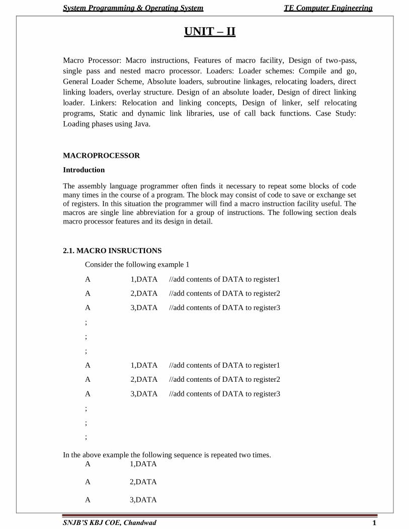
Consider the following example 1
A 1,DATA //add contents of DATA to register1
A 2,DATA //add contents of DATA to register2
A 3,DATA //add contents of DATA to register3
;
;
;
A 1,DATA //add contents of DATA to register1
A 2,DATA //add contents of DATA to register2
A 3,DATA //add contents of DATA to register3
;
;
;
In the above example the following sequence is repeated two times.
A 1,DATA
A 2,DATA
A 3,DATA
System Programming & Operating System TE Computer Engineering
2 SNJB’S KBJ COE, Chandwad
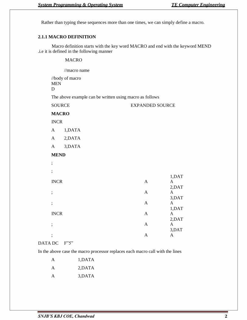
Rather than typing these sequences more than one times, we can simply define a macro.
2.1.1 MACRO DEFINITION
Macro definition starts with the key word MACRO and end with the keyword MEND .i.e it is defined in the following manner
MACRO
//macro name
//body of macro
MEN
D
The above example can be written using macro as follows
SOURCE EXPANDED SOURCE
MACRO
INCR
A 1,DATA
A 2,DATA
A 3,DATA
MEND
;
;
INCR
A 1,DAT A
;
A 2,DAT A
;
A 3,DAT A
INCR
A 1,DAT A
;
A 2,DAT A
;
A 3,DAT
A
DATA DC F‟5‟
In the above case the macro processor replaces each macro call with the lines
A 1,DATA
A 2,DATA
A 3,DATA
System Programming & Operating System TE Computer Engineering
The macro invocation can be done by using macro name ,in this case it is INCR.
The process of replacement is called expanding the macro. In the above case the macro definition is not appeared in the expanded source code.
2.2 FEATURES OF MACROPROCESSOR
2.2.1 Macro instruction arguments
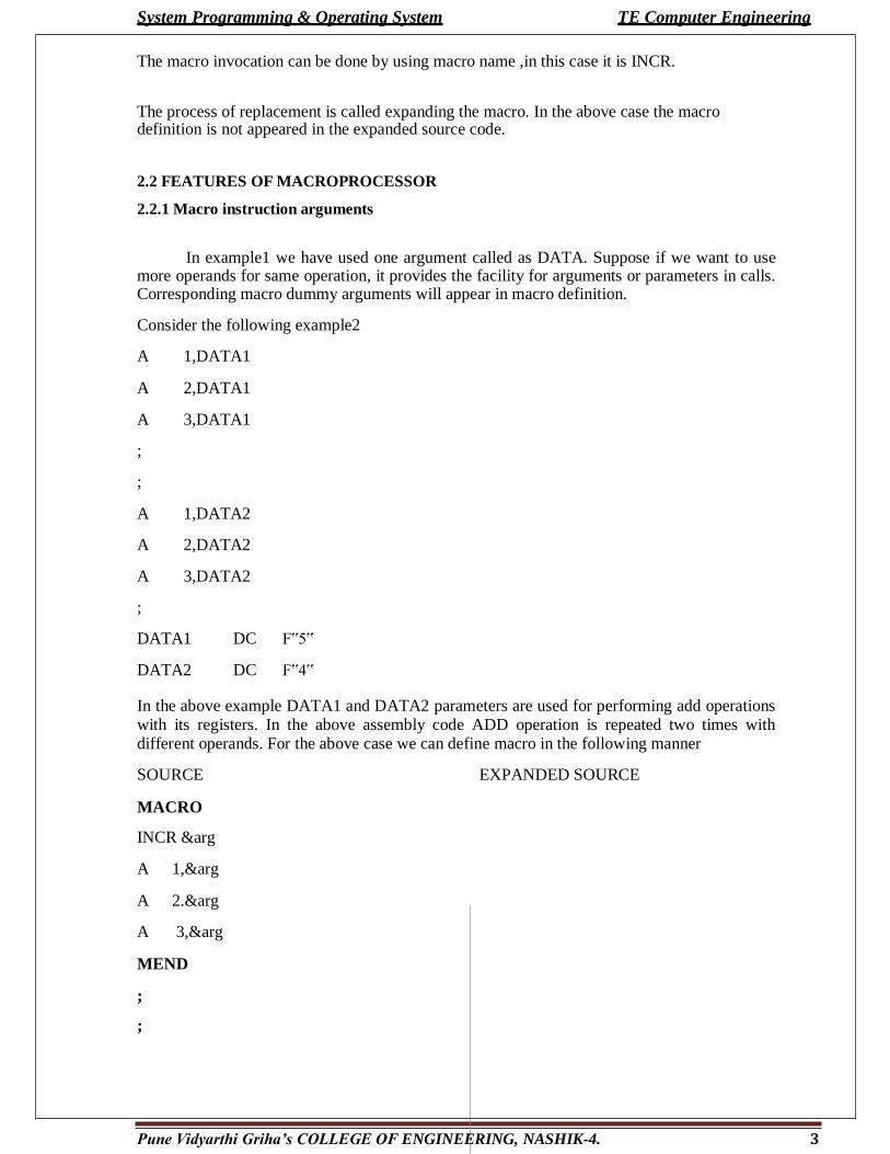
In example1 we have used one argument called as DATA. Suppose if we want to use more operands for same operation, it provides the facility for arguments or parameters in calls. Corresponding macro dummy arguments will appear in macro definition.
Consider the following example2
A 1,DATA1
A 2,DATA1
A 3,DATA1
;
;
A 1,DATA2
A 2,DATA2
A 3,DATA2
;
DATA1 DC F‟5‟
DATA2 DC F‟4‟
In the above example DATA1 and DATA2 parameters are used for performing add operations with its registers. In the above assembly code ADD operation is repeated two times with different operands. For the above case we can define macro in the following manner
SOURCE EXPANDED SOURCE
MACRO
INCR &arg
A 1,&arg
A 2.&arg
A 3,&arg
MEND
;
;
Pune Vidyarthi Griha’s COLLEGE OF ENGINEERING, NASHIK-4. 3
System Programming & Operating System TE Computer Engineering
4 Pune Vidyarthi Griha’s COLLEGE OF ENGINEERING, NASHIK-4.
INCR
DATA1
use data1 as operand
A
1,DATA1
; A 2,DATA1
A 3,DATA1
INCR DATA2 use data2 as operand A 1,DATA2
; A 2,DATA2
; A 3,DATA2
DATA1 DC F‟5‟ DATA1 DC F‟5‟
DATA2 DC F‟4‟ DATA2 DC F‟4‟
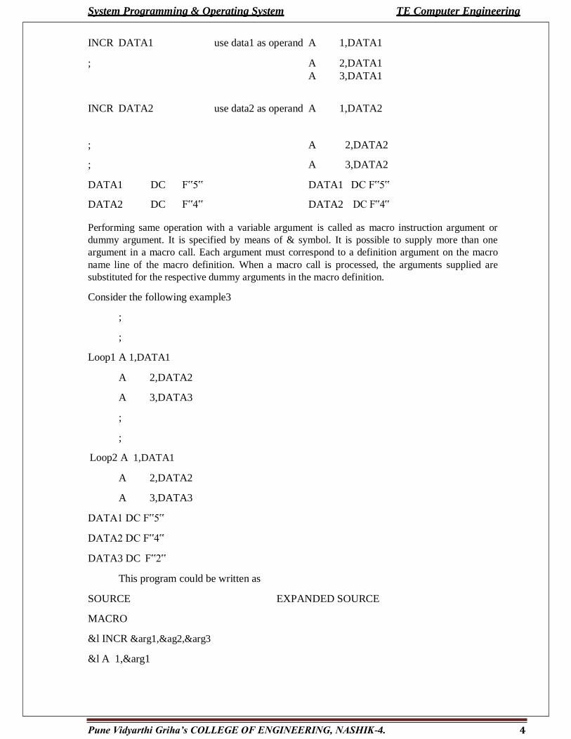
Performing same operation with a variable argument is called as macro instruction argument or
dummy argument. It is specified by means of & symbol. It is possible to supply more than one
argument in a macro call. Each argument must correspond to a definition argument on the macro
name line of the macro definition. When a macro call is processed, the arguments supplied are
substituted for the respective dummy arguments in the macro definition.
Consider the following example3
;
;
Loop1 A 1,DATA1
A 2,DATA2
A 3,DATA3
;
;
Loop2 A 1,DATA1
A 2,DATA2
A 3,DATA3
DATA1 DC F‟5‟
DATA2 DC F‟4‟
DATA3 DC F‟2‟
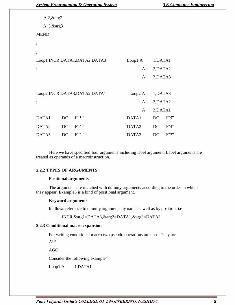
This program could be written as
SOURCE EXPANDED SOURCE
MACRO
&l INCR &arg1,&ag2,&arg3
&l A 1,&arg1
System Programming & Operating System TE Computer Engineering
5 Pune Vidyarthi Griha’s COLLEGE OF ENGINEERING, NASHIK-4.
A 2,&arg2
A 3,&arg3
MEND
;
;
Loop1 INCR DATA1,DATA2,DATA3 Loop1 A 1,DATA1
; A 2,DATA2
A 3,DATA3
Loop2 INCR DATA3,DATA2,DATA1
Loop2 A
1,DATA3
; A 2,DATA2
A 3,DATA1
DATA1 DC F‟5‟ DATA1 DC F‟5‟
DATA2 DC F‟4‟ DATA2 DC F‟4‟
DATA3 DC F‟2‟ DATA3 DC F‟2‟
Here we have specified four arguments including label argument. Label arguments are
treated as operands of a macroinstruction.
2.2.2 TYPES OF ARGUMENTS
Positional arguments
The arguments are matched with dummy arguments according to the order in which they appear. Example3 is a kind of positional argument.
Keyword arguments
It allows reference to dummy arguments by name as well as by position. i.e
INCR &arg1=DATA3,&arg2=DATA1,&arg3=DATA2.
2.2.3 Conditional macro expansion
For writing conditional macro two pseudo operations are used. They are
AIF
AGO
Consider the following example4
Loop1 A 1,DATA1

System Programming & Operating System TE Computer Engineering
6 Pune Vidyarthi Griha’s COLLEGE OF ENGINEERING, NASHIK-4.
A 2,DATA2
A 3,DATA3
;
;
Loop2 A 1,DATA1
A 2,DATA2
Loop3
A
1,DATA1
DATA1 DC F‟5‟
DATA2 DC F‟4‟
DATA3 DC F‟2‟
In the above example under each loop variable number of arguments is used. The program could be written by using only conditional macro
MACRO
&argvary &count,&arg1,&arg2,&arg3
&arg0A 1,&arg1
AIF (&count EQ 1).FINI
A 2,&arg2
AIF (&count EQ 2).FINI
A 3,&arg3
.FINI MEND EXPANDED SOURCE
Loop1 vary 3,DATA1,DATA2,DATA3 Loop1 A 1,DATA3
; A 2,DATA2
; A 3,DATA1
;
Loop2 vary 2,DATA3,DATA2 Loop2 A 1,DATA3
; A 2,DATA2
;
Loop3 vary 1,DATA1 Loop3 A 1,DATA1
;
;
DATA1 DC F‟5‟ DATA1 DC F‟5‟
7 Pune Vidyarthi Griha’s COLLEGE OF ENGINEERING, NASHIK-4.
e System Programming & Operating Syst m TE Computer Engineering
DATA2
DC
F‟4‟
DATA2
DC
F‟4‟
DATA3 DC F‟2‟ DATA3 DC F‟2‟
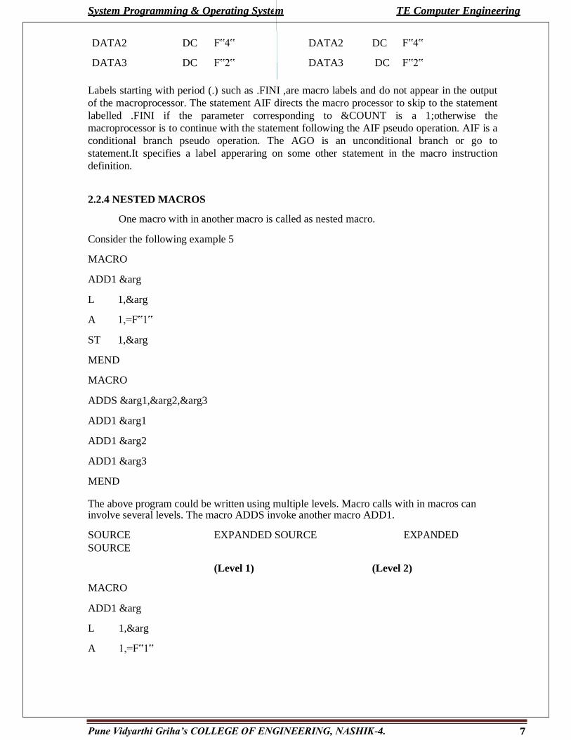
Labels starting with period (.) such as .FINI ,are macro labels and do not appear in the output
of the macroprocessor. The statement AIF directs the macro processor to skip to the statement
labelled .FINI if the parameter corresponding to &COUNT is a 1;otherwise the
macroprocessor is to continue with the statement following the AIF pseudo operation. AIF is a
conditional branch pseudo operation. The AGO is an unconditional branch or go to
statement.It specifies a label apperaring on some other statement in the macro instruction
definition.
2.2.4 NESTED MACROS
One macro with in another macro is called as nested macro.
Consider the following example 5
MACRO
ADD1 &arg
L 1,&arg
A 1,=F‟1‟
ST 1,&arg
MEND
MACRO
ADDS &arg1,&arg2,&arg3
ADD1 &arg1
ADD1 &arg2
ADD1 &arg3
MEND
The above program could be written using multiple levels. Macro calls with in macros can involve several levels. The macro ADDS invoke another macro ADD1.
SOURCE EXPANDED SOURCE EXPANDED
SOURCE
(Level 1) (Level 2)
MACRO
ADD1 &arg
L 1,&arg
A 1,=F‟1‟

8 Pune Vidyarthi Griha’s COLLEGE OF ENGINEERING, NASHIK-4.
System Programming & Operating System TE Computer Engineering
ST
1,&arg
MEND
MACRO
ADDS &arg1,&arg2,&arg3
ADD1 &arg1
ADD1 &arg2
ADD1 &arg3
MEND
SOURCE EXPANDED SOURCE EXPANDED SOURCE
(Level 1) (Level 2)
;
; //expansion of ADD1
ADDS DATA1,DATA2,DATA3 ADD1 DATA1 L 1,DATA1
A 1,=F‟1‟
ST 1,DATA1
ADD1 DATA2 L 1,DATA2
A 1,=F‟1‟
ST 1,DATA2
ADD1 DATA3 L 1,DATA3
A 1,=F‟1‟
ST 1,DATA3
2.3 MACROPROCESSOR IMPLEMENTATION
It involves four steps. They are
1. Recognize macro definitions
Macro processor must recognize macro definitions identified by the MACRO and MEND pseudo operations.
2. Save the definitions
Macro definitions should be saved in MACRO DEFINITION TABLE (MDT) 3. Recognize calls
The processor must recognize macro calls that appear as operation mnemonics. 4. Expand calls and substitute arguments
The processor must substitute for dummy argument corresponding arguments from a macro call.S
9 Pune Vidyarthi Griha’s COLLEGE OF ENGINEERING, NASHIK-4.
System Programming & Operating System TE Computer Engineering
2.3.1 A two pass algorithm
A macro processor, like an assembler, scans and processes lines of text. The macro
processor algorithm will make two systematic scans or passes over the input text, searching
first for macro definitions and then for macro calls. The assembler cannot process a
reference to a symbol before its definitions, in the same way the macro processor cannot
expand a macro call before having and saved the corresponding macro definition. Thus we
need two pass over the input text, one to handle definitions and one to handle macro calls.
The first pass examining every operation code, and save all macro definitions in a macro
definition table (MDT). The first pass will also prepare a Macro Name Table (MNT) along
with MDT. The second pass will then examine every mnemonic and replace each macro
name with the appropriate text from the macro definitions.
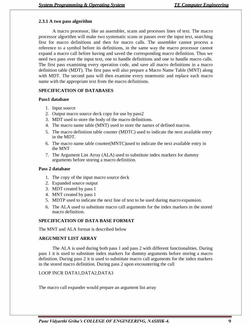
SPECIFICATION OF DATABASES
Pass1 database
1. Input source
2. Output macro source deck copy for use by pass2
3. MDT used to store the body of the macro definitions.
4. The macro name table (MNT) used to store the names of defined macros.
5. The macro definition table counter (MDTC) used to indicate the next available entry in the MDT.
6. The macro name table counter(MNTC)used to indicate the next available entry in the MNT
7. The Argument List Array (ALA) used to substitute index markers for dummy arguments before storing a macro definition.
Pass 2 database
1. The copy of the input macro source deck
2. Expanded source output
3. MDT created by pass 1
4. MNT created by pass 1
5. MDTP used to indicate the next line of text to be used during macro expansion.
6. The ALA used to substitute macro call arguments for the index markers in the stored macro definition.
SPECIFICATION OF DATA BASE FORMAT
The MNT and ALA format is described below
ARGUMENT LIST ARRAY
The ALA is used during both pass 1 and pass 2 with different functionalities. During pass 1 it is used to substitute index markers for dummy arguments before storing a macro definition. During pass 2 it is used to substitute macro call arguments for the index markers in the stored macro definition. During pass 2 upon encountering the call
LOOP INCR DATA1,DATA2,DATA3
The macro call expander would prepare an argument list array

System Programming & Operating System TE Computer Engineering
index Arguments
0 LOOP1
1 DATA1
2 DATA2
3 DATA3
MACRO DEFINITION TABLE FORMAT
The MDT is a table of text lines . Every line of each macro definition, except MACRO line is stored in MDT. The MEND is kept to indicate the end of the definition.
Macro definition table
80 bytes per entry
Index source
; ;
; ;
20 &LAB INCR &arg1,&arg2,&arg3
21 A 1,&arg1
22 A 2,&arg2
23 A 3,&arg3
MEND
MACRO NAME TABLE
This table is used to store the name in MNT
Index MNAMEMDT index
; ; ;
3 INCR 20
Pune Vidyarthi Griha’s COLLEGE OF ENGINEERING, NASHIK-4. 10
System Programming & Operating System TE Computer Engineering
11 Pune Vidyarthi Griha’s COLLEGE OF ENGINEERING, NASHIK-4.
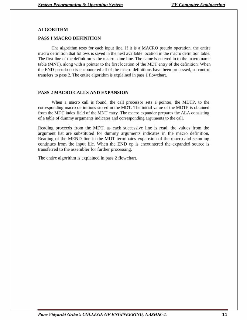
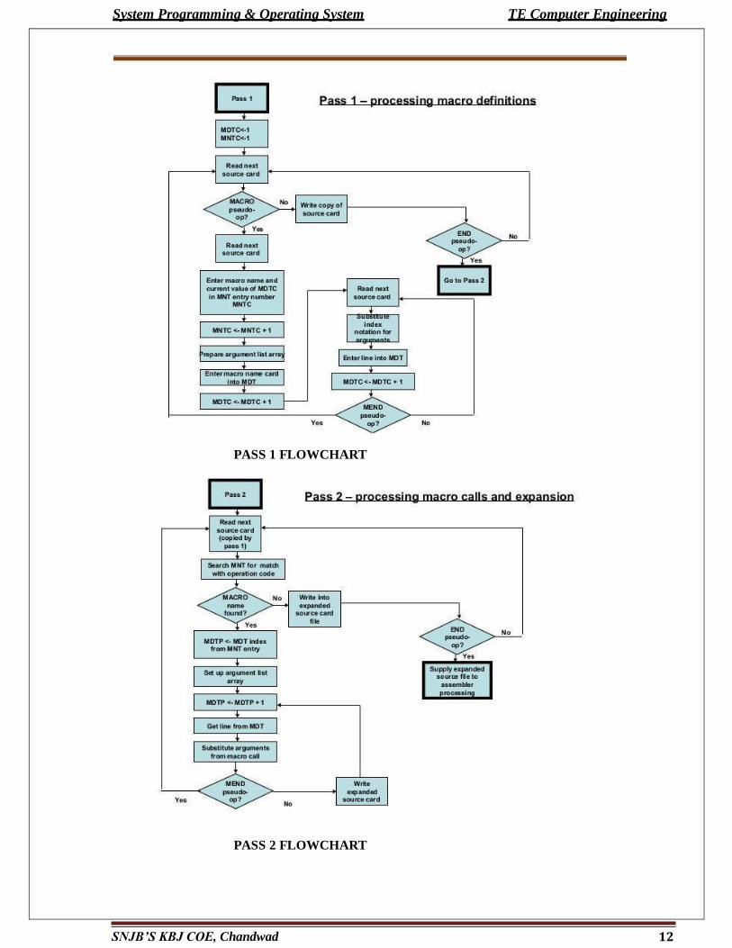
ALGORITHM
PASS I MACRO DEFINITION
The algorithm tests for each input line. If it is a MACRO pseudo operation, the entire
macro definition that follows is saved in the next available location in the macro definition table.
The first line of the definition is the macro name line. The name is entered in to the macro name
table (MNT), along with a pointer to the first location of the MDT entry of the definition. When
the END pseudo op is encountered all of the macro definitions have been processed, so control
transfers to pass 2. The entire algorithm is explained in pass 1 flowchart.
PASS 2 MACRO CALLS AND EXPANSION
When a macro call is found, the call processor sets a pointer, the MDTP, to the
corresponding macro definitions stored in the MDT. The initial value of the MDTP is obtained
from the MDT index field of the MNT entry. The macro expander prepares the ALA consisting
of a table of dummy arguments indicates and corresponding arguments to the call.
Reading proceeds from the MDT, as each successive line is read, the values from the
argument list are substituted for dummy arguments indicates in the macro definition.
Reading of the MEND line in the MDT terminates expansion of the macro and scanning
continues from the input file. When the END op is encountered the expanded source is
transferred to the assembler for further processing.
The entire algorithm is explained in pass 2 flowchart.
System Programming & Operating System TE Computer Engineering
12 SNJB’S KBJ COE, Chandwad
PASS 1 FLOWCHART
PASS 2 FLOWCHART
System Programming & Operating System TE Computer Engineering
13 SNJB’S KBJ COE, Chandwad
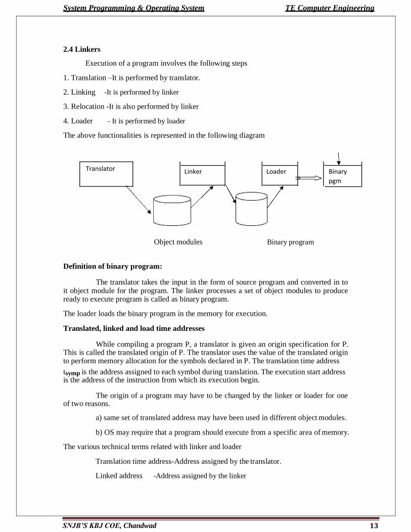
2.4 Linkers
Execution of a program involves the following steps
1. Translation –It is performed by translator.
2. Linking -It is performed by linker
3. Relocation -It is also performed by linker
4. Loader - It is performed by loader
The above functionalities is represented in the following diagram
Translator Linker
Loader
Binary
pgm
Object modules Binary program
Definition of binary program:
The translator takes the input in the form of source program and converted in to it object module for the program. The linker processes a set of object modules to produce ready to execute program is called as binary program.
The loader loads the binary program in the memory for execution.
Translated, linked and load time addresses
While compiling a program P, a translator is given an origin specification for P. This is called the translated origin of P. The translator uses the value of the translated origin to perform memory allocation for the symbols declared in P. The translation time address
tsymp is the address assigned to each symbol during translation. The execution start address is the address of the instruction from which its execution begin.
The origin of a program may have to be changed by the linker or loader for one of two reasons.
a) same set of translated address may have been used in different object modules.
b) OS may require that a program should execute from a specific area of memory.
The various technical terms related with linker and loader
Translation time address-Address assigned by the translator.
Linked address -Address assigned by the linker

System Programming & Operating System TE Computer Engineering
14 SNJB’S KBJ COE, Chandwad
Load time address - Address assigned by the loader
Consider the following assembly program P with its generated code
SOURCE PGM ADDRESS CODE
START 500
ENTRY TOTAL
EXTRN MAX.ALPHA
READ A
LOOP ; 500 09 0 540
; 501
MOVER AREG,ALPHA 518 04 1 000
BC ANY,MAX 519 06 6 000
;
BC LT,LOOP 538 06 1 501
STOP 539 00 0 000
A
DS 1
540
TOTAL DS 1 541
END
RELOCATION AND LINKING CONCEPTS
Program relocation
Let AA be the set of absolute address-instructions or data addresses used in the instruction of a program P. AA !=0, implies that program P assumes its instructions and data to occupy memory words with specific address. Such a program is called as address sensitive program.
Address sensitive program contains the following
1. Address sensitive instruction
2. Address constant
Definition
Program relocation is the process of modifying the address used in the address sensitive instructions of a program such that the program can execute correctly from the designated area of memory.
System Programming & Operating System TE Computer Engineering
15 SNJB’S KBJ COE, Chandwad
If the linked origin ≠ translated origin, relocation must be performed by the linker.
If the load origin ≠linked origin, then relocation must be performed by the loader. In general ,a linker always performs relocation where as some loader do not.
Detailed explanation:
Consider the above example program. Assume that origin of the program is
500. The translation time address of a symbol A is 540. The instruction corresponding to
the statement READ A uses the address 540, hence it is an address sensitive instruction. If
the linked origin is 900, A would have the link time address 940. Hence the address in the
READ instruction should be corrected to 940. Similarly the instruction in translated
memory word contains 501, the address of LOOP. This should be corrected to 901.
Performing relocation
Let the Translated origin of the program P is t-origin p
Let the linked origin of the program P is l-originp . Consider a symbol symp in P.
Let its translation time address be tsymp . and its link time address lsymp . The relocation
factor is defined as the difference between linked origin and translated orgin for the P.
Relocation factor p=l-origin p – t-origin p (1)
Relocation factor p can be positive ,negative or zero.
Consider a statement which uses a symp as an operand. The translator puts the address
tsymp in the instruction generated for it.
tsymp = t-origin p+dsymp
where dsymp is the offset of symp in P. Hence
using equation (1)
lsymp = t-origin p + Relocation factor p + dsymp
= t-origin p + dsymp + Relocation factor p
=tsymp + Relocation factor p (2)
Using equation (2) the relocation factor for the above program is 400.
Linking
Consider an application program AP consisting of a set of program units SP={Pi} .
A program unit Pi interacts with another program unit Pj by using addresses of Pj
instructions and data in its own instructions. To link with different programs it contains public definitions and external references.
Public definition:
The symbol defined in the current program unit is referred by other program.
System Programming & Operating System TE Computer Engineering
16 SNJB’S KBJ COE, Chandwad
External reference:
The symbol which is not defined in the program unit containing the reference.
EXTERN and ENTRY statements
The ENTRY statement lists the public definitions of a program unit. i.e it lists those symbols defined in the program unit which may be referenced in other program units. The EXTERN statement lists the symbol to which external references are made in the program unit.
Resolving external references
Definition
Linking is the process of binding an external reference to the correct time link address. An external reference is said to be unsolved until linking is performed for it. It is said to be resolved when its linking is completed.
Consider the following program Q
Source address code
START 200
ENTRY ALPHA
------
------
ALPHA DS 25 231 00 0 025
END
DETAILED EXPLANATION
LINKING PROGRAM P WITH Q
Program unit P contains an external reference to the symbol ALPHA which is a public
definition in Q with the translation time address 231. Let the link origin of P is 900 and its
size be 42 words. The link origin of Q is therefore 942, and the link time address of
ALPHA is 973. Linking is performed by putting the link time address of ALPHA in the
instruction of P using ALPHA.
Binary programs
A binary program is a machine language program comprising a set of program units SP such that the following constraints to be satisfied
1. Pi has been relocated to the memory area starting at its link origin
2. Linking has been performed for each external reference in Pi
To form a binary program from a set of object modules, the programmer invokes the linker using the command
Linker <link origin>,<object module names>, [,<execution start address>]
System Programming & Operating System TE Computer Engineering
17 SNJB’S KBJ COE, Chandwad
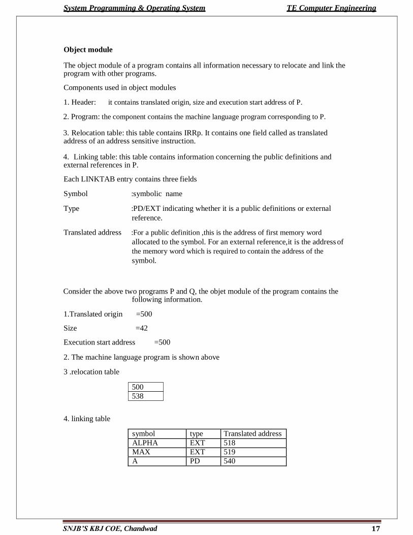
538
Object module
The object module of a program contains all information necessary to relocate and link the program with other programs.
Components used in object modules
1. Header: it contains translated origin, size and execution start address of P.
2. Program: the component contains the machine language program corresponding to P.
3. Relocation table: this table contains IRRp. It contains one field called as translated address of an address sensitive instruction.
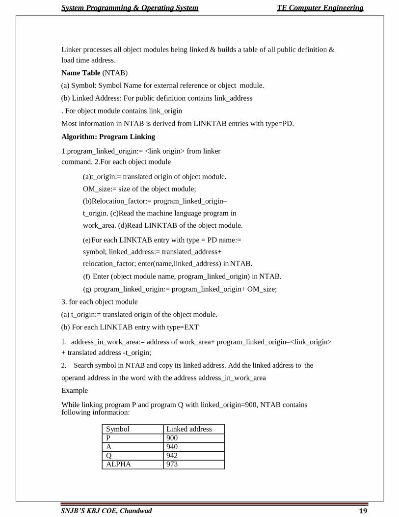
4. Linking table: this table contains information concerning the public definitions and external references in P.
Each LINKTAB entry contains three fields
Symbol :symbolic name
Type :PD/EXT indicating whether it is a public definitions or external
reference.
Translated address :For a public definition ,this is the address of first memory word
allocated to the symbol. For an external reference,it is the address of
the memory word which is required to contain the address of the
symbol.
Consider the above two programs P and Q, the objet module of the program contains the
following information.
1.Translated origin =500
Size =42
Execution start address =500
2. The machine language program is shown above
3 .relocation table
4. linking table
symbol type Translated address
ALPHA EXT 518
MAX EXT 519
A PD 540
500

System Programming & Operating System TE Computer Engineering
18 SNJB’S KBJ COE, Chandwad
The above 4 informations are required for designing linker.
2.5 DESIGN OF A LINKER
2.5.1 Algorithm (Program relocation)
1.program_linked_origin:=<link origin> from Linker
command; 2.For each object module
(a) t_origin:= translated origin of object
module; OM_size:= size of object module;
(b) relocation_factor:= program_linked_origin–t_origin;
(c) Read the machine language program in work_area;
(d) Read RELOCTAB of object module.
(e) For each entry in RELOCTAB
(i) Translated_addr= address in RELOCTAB entry;
(ii) address_in_work_area= address of work_area+translated_address–t_origin;
(iii) Add relocation_factorto the operand address in the word with the address
„address_in_work_area‟.
(f) Program_linked_origin:= program_linked_origin+ OM_Size;
Example:
Let address of work_area= 300.
While relocating OM, relocation factor =400.
For the first RELOCTAB entry, address_in_work_area= 300+500-500=300.This word
contains the instruction for READ A. It is reallocated by adding 400 to operand address in
it. For the second RELOCTAB entry,address_in_work_area=300+538-500=338. The
instruction in this word is similarly relocated by adding 400 to the operand address in it.
2.5.2 Linking Requirements:
In FORTRAN all program units are translated separately.
Hence, all sub program calls and common variable reference require
linking. Programs are nested in main program.
Procedure reference does not require linking they can be handled using
relocation. Build in functions require linking
System Programming & Operating System TE Computer Engineering
19 SNJB’S KBJ COE, Chandwad
Linker processes all object modules being linked & builds a table of all public definition &
load time address.
Name Table (NTAB)
(a) Symbol: Symbol Name for external reference or object module.
(b) Linked Address: For public definition contains link_address
. For object module contains link_origin
Most information in NTAB is derived from LINKTAB entries with type=PD.
Algorithm: Program Linking
1.program_linked_origin:= <link origin> from linker
command. 2.For each object module
(a)t_origin:= translated origin of object module.
OM_size:= size of the object module;
(b)Relocation_factor:= program_linked_origin–
t_origin. (c)Read the machine language program in
work_area. (d)Read LINKTAB of the object module.
(e) For each LINKTAB entry with type = PD name:=
symbol; linked_address:= translated_address+
relocation_factor; enter(name,linked_address) in NTAB.
(f) Enter (object module name, program_linked_origin) in NTAB.
(g) program_linked_origin:= program_linked_origin+ OM_size;
3. for each object module
(a) t_origin:= translated origin of the object module.
(b) For each LINKTAB entry with type=EXT
1. address_in_work_area:= address of work_area+ program_linked_origin–<link_origin>
+ translated address -t_origin;
2. Search symbol in NTAB and copy its linked address. Add the linked address to the
operand address in the word with the address address_in_work_area
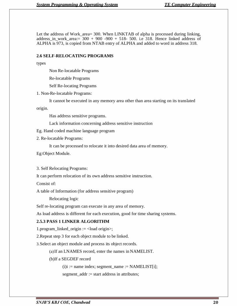
Example
While linking program P and program Q with linked_origin=900, NTAB contains following information:
Symbol Linked address
P 900
A 940
Q 942
ALPHA 973
System Programming & Operating System TE Computer Engineering
20 SNJB’S KBJ COE, Chandwad
Let the address of Work_area= 300. When LINKTAB of alpha is processed during linking, address_in_work_area:= 300 + 900 -900 + 518- 500. i.e 318. Hence linked address of ALPHA is 973, is copied from NTAB entry of ALPHA and added to word in address 318.
2.6 SELF-RELOCATING PROGRAMS
types
Non Re-locatable Programs
Re-locatable Programs
Self Re-locating Programs
1. Non-Re-locatable Programs:
It cannot be executed in any memory area other than area starting on its translated
origin.
Has address sensitive programs.
Lack information concerning address sensitive instruction
Eg. Hand coded machine language program
2. Re-locatable Programs:
It can be processed to relocate it into desired data area of memory.
Eg:Object Module.
3. Self Relocating Programs:
It can perform relocation of its own address sensitive instruction.
Consist of:
A table of Information (for address sensitive program)
Relocating logic
Self re-locating program can execute in any area of memory.
As load address is different for each execution, good for time sharing systems.
2.5.3 PASS 1 LINKER ALGORITHM
1.program_linked_origin := <load origin>;
2.Repeat step 3 for each object module to be linked.
3. Select an object module and process its object records.
(a) If an LNAMES record, enter the names in NAMELIST.
(b)If a SEGDEF record
(i)i := name index; segment_name := NAMELIST[i];
segment_addr := start address in attributes;

System Programming & Operating System TE Computer Engineering
21 SNJB’S KBJ COE, Chandwad
segments
If an absolute segment, enter (segment_name, segment_addr) in NTAB.
If the segment is re-locatable and cannot be combined with other
-Align the address containing in program_linked_origin on
the next word or paragraph as indicated in attribute list.
-Enter (segment_name,program_linked_origin) in NTAB. -
program_linked_origin := program load origin + segment length;
- For each PUBDEF record
i := base; segment_name := NAMELIST[i];
segment_addr := load address of segment_name in NTAB;
sym_addr := segment_addr + offset;
Enter (symbol,sym_addr) in NTAB.
In first pass, linker only processes the object records relevant for building NTAB.
Second pass performs relocation and linking
2.5.4 Pass II LINKER ALGORITHM
1.List_of_object_module:= object modules named in LINKER
command; 2.Repeat step 3 until list_of_object_modules is empty.
3. Select an object module and process its object records.
a) if an LNAMES record Enter the names in NAMELIST.
c. if a SEGDEF recordi := name index; segment_name := NAMELIST[i];
d. if an EXTDEF record
external_name := name from EXTDEF record;
if external_name is not found in NTAB, then
-Locate object module in library which contains
external_name as a segment or public definition.
-Add name of object module to list_of_object_module. -
Perform first pass of LINKER, for new object module.
(iii) Enter (external_name, load address from NTAB) in EXTTAB.
(d) if an LEDATA record
(i) i:= segment index; d:=data offset;
(ii) program_load_origin:= SEGTAB[i].load address;
System Programming & Operating System TE Computer Engineering
22 SNJB’S KBJ COE, Chandwad
(iii) address_in_work_area := address of work_area + program_load_origin -
<load origin> + d;
1. move data from LEDATA into the memory area starting at the address
address_in_work_area.
(e) if a FIXUPP record, for each FIXUPP specification
f := offset from locat field;
fix_up_address := address_in_work_area + f;
Perform required fix up using a load address from SEGTAB or EXTTAB and the
value of code in locat and fix dat.
(f) if MODEND record
if start address is specified, compute the corresponding load address and record it in the
executable file being generated.
2.7 LOADER
Introduction
The loader is a program which takes this object program, prepares it for execution,
and loads this executable code of the source into memory for execution.
Definition:
Loader is utility program which takes object code as input prepares it for execution and
loads the executable code in to the memory. Thus loader is actually responsible for
initiating the execution process.
Functions of loader
The loader is responsible for the activities such as allocation, linking, relocation and loading
1) It allocates the space for program in the memory, by calculating the size of the program.
This activity is called allocation.
2) It resolves the symbolic references (code/data) between the object modules by assigning
all the user subroutine and library subroutine addresses. This activity is called linking.
3) There are some address dependent locations in the program, such address constants must
be adjusted according to allocated space, such activity done by loader is called relocation.
4) Finally it places all the machine instructions and data of corresponding programs and
subroutines into the memory. Thus program now becomes ready for execution.
System Programming & Operating System TE Computer Engineering
23 SNJB’S KBJ COE, Chandwad
2.7.1 Types of loader
1. Compile and go to loader
2. General loader 3. absolute loader 4. direct linking loader (DLL)
1. Compile and go” loader:
In this type of loader, the instruction is read line by line, its machine code is
obtained and it is directly put in the main memory at some known address. That means the
assembler runs in one part of memory and the assembled machine instructions and the data
is directly put into their assigned memory locations. After completion of assembly process,
assign starting address of the program to the location counter. The typical example is
WATFOR-77, it‟s a FORTRAN compiler which uses such “load and go” scheme. This
loading scheme is also called as “assemble and go”.
Advantages:
This scheme is simple to implement. Because assembler is placed at one part of the
memory and loader simply loads assembled machine instructions into the memory.
Disadvantages:
1. In this scheme some portion of memory is occupied by assembler which is simply
wastage of memory. As this scheme is combination of assembler and loader activities, this
combination program occupies large block of memory.
2. There is no production of .obj file, the source code is directly converted to
executable form. Hence even though there is no modification in the source program it needs
to be assembled and executed each time, which then becomes a time consuming activity.
I3. it cannot handle multiple source programs or multiple programs written in different
languages. This is because assembler can translate one source language to other target
language.
4. For a programmer it is very difficult to make an orderly modulator program and also
it becomes difficult to maintain such program, and the “compile and go” loader cannot
handle such programs.
5. The execution time will be more in this scheme as every time program is assembled
and then executed
General Loader Scheme:
In this loader scheme, the source program is converted to object program by some translator
(assembler). The loader accepts these object modules and puts machine instruction and data
System Programming & Operating System TE Computer Engineering
24 SNJB’S KBJ COE, Chandwad
in an executable form at their assigned memory. The loader occupies some portion of main
memory.
Advantages:
The program need not be retranslated each time while running it. This is because initially
when source program gets executed an object program gets generated. Of program is not
modified, then loader can make use of this object program to convert it to executable form.
There is no wastage of memory, because assembler is not placed in the memory, instead of
it, loader occupies some portion of the memory. And size of loader is smaller than
assembler, so more memory is available to the user.
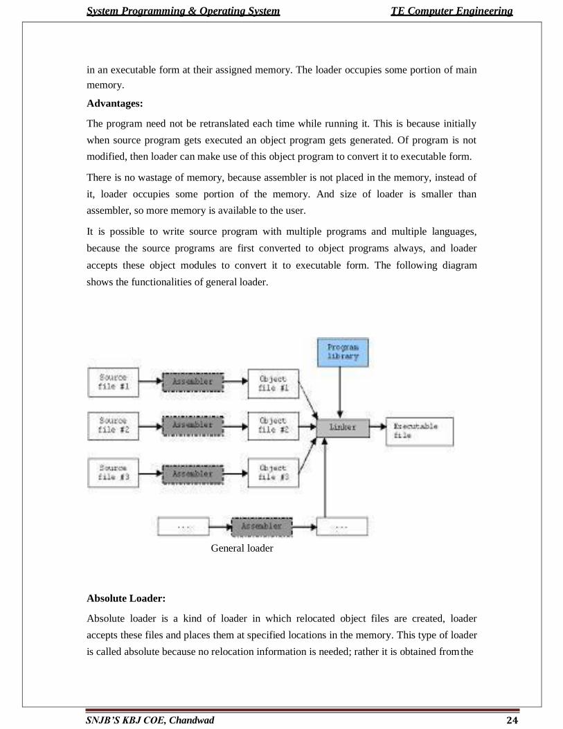
It is possible to write source program with multiple programs and multiple languages,
because the source programs are first converted to object programs always, and loader
accepts these object modules to convert it to executable form. The following diagram
shows the functionalities of general loader.
General loader
Absolute Loader:
Absolute loader is a kind of loader in which relocated object files are created, loader
accepts these files and places them at specified locations in the memory. This type of loader
is called absolute because no relocation information is needed; rather it is obtained from the
System Programming & Operating System TE Computer Engineering
25 SNJB’S KBJ COE, Chandwad
programmer or assembler. The starting address of every module is known to the
programmer, this corresponding starting address is stored in the object file, then task of
loader becomes very simple and that is to simply place the executable form of the machine
instructions at the locations mentioned in the object file
In this scheme, the programmer or assembler should have knowledge of memory management.
The resolution of external references or linking of different subroutines are the issues which
need to be handled by the programmer. The programmer should take care of two things: first
thing is specification of starting address of each module to be used. If some modification is
done in some module then the length of that module may vary. This causes a change in the
starting address of immediate next. modules, its then the programmer's duty to make necessary
changes in the starting addresses of respective modules. Second thing is, while branching from
one segment to another the absolute starting address of respective module is to be known by the
programmer so that such address can be specified at respective
JMP instruction. For example
Line number
1
.
MAIN START 1000
.
. .
. .
1 JMP 5000
16 STORE ;instruction at location 2000
END
1
SUM
START 5000
2
20 JMP 2000
21 END
In this example there are two segments, which are interdependent. At line number 1 the
assembler directive START specifies the physical starting address that can be used during
the execution of the first segment MAIN.
Then at line number 15 the JMP instruction is given which specifies the physical starting
address that can be used by the second segment. The assembler creates the object codes for
System Programming & Operating System TE Computer Engineering
26 SNJB’S KBJ COE, Chandwad
these two segments by considering the stating addresses of these two segments. During the
execution, the first segment will be loaded at address 1000 and second segment will be
loaded at address 5000 as specified by the programmer. Thus the problem of linking is
manually solved by the programmer itself by taking care of the mutually dependant dresses.
As you can notice that the control is correctly transferred to the address 5000 for invoking
the other segment, and after that at line number 20 the JMP instruction transfers the control
to the location 2000, necessarily at location 2000 the instruction STORE of line number 16
is present. Thus resolution of mutual references and linking is done by the programmer.
The task of assembler is to create the object codes for the above segments and along with
the information such as starting address of the memory where actually the object code can
be placed at the time of execution. The absolute loader accepts these object modules from
assembler and by reading the information about their starting addresses, it will actually
place (load) them in the memory at the specified address.
Advantages
1. It is easy to implement
2. this scheme allows multiple programs in different languages.
3. the task of loader becomes simpler as its simply obeys the instruction regarding where
to place the object code in memory.
4. the process of execution is efficient.
Disadvantages
Overlapping
Absolute loader algorithm:
begin
Read header record
Verify program name and length
Read first TEXT record
While record type!=E
do begin
{If object code is in character form, convert into internal
representation} Move object code to specified location in memory
Read the next object program record
System Programming & Operating System TE Computer Engineering
27 SNJB’S KBJ COE, Chandwad
end
end
jump to address specified in END record
Design of direct linking loader (DLL)
The direct linking loader has the advantage of allowing the programmer multiple
procedure segments and multiple data segments and allows complete freedom in
referencing data or instructions contained in other segments. This provides flexible
intersegment referencing and accessing ability ,while at the same time allowing
independent translation of programs.
The translator must give the loader the following information with each procedure
or data segment.
1. The length of segment
2. A list of all symbols in the segment that may be referenced by other segment and
their relative location with in the segment
3. A list of all symbols not defined in the segment but referenced in the segment
4. Information as to where address constants are located in the segment and a
description of how to revise their values
5. The machine code translation of the source program and the relative address assigned.
There are four sections to the object desk
1. External symbol directory cards(ESD)
2. Instructions and data cards called text of a program(TXT)
3. Relocation and linkage directory cards (RLD)
4. End card(END)
The ESD cards contain the information necessary to build the external directory or
symbol table. External symbols are symbols that can be referred beyond the subroutine
level.
EXAMPLE

System Programming & Operating System TE Computer Engineering
28 SNJB’S KBJ COE, Chandwad
Assume program B has a table called NAMES. It can be accessed by program A as
follows
A START
EXTRN NAMES
;
L 1,ADDRNAME //get address of NAME table
;
ADDRNAME DC A(NAMES)
END
B START
ENTRY NAMES
;
;
NAMES DC
END
There are three types of external symbol
1. segment definition(SD)
2. Local definition(LD) specified on ENTRY card
3. External reference(ER) specified on EXTRN card
The TXT cards contain block of data and the relative address at which the data is
placed. Once the loader has decided where to load the program ,it merely adds the
program load address(PLA) to the relative address and moves the data in to the resulting
location.
The RLD card contain the following information

System Programming & Operating System TE Computer Engineering
29 SNJB’S KBJ COE, Chandwad
1. The location and length of each address constant that needs to be changed for
relocation or linking
2. The external symbol by which the address constant should be modified
3.The operation to be performed.
The END card specifies the end of the object deck. For every subroutine we need to
prepare ESD,TXT,RLD and END cards
ESD card format
TXT cards
RLD cards
Used Data structures required for designing two pass direct linking loader scheme
Pass 1 database
1. input object deck
2.A parameter initial program load address(IPLA)
3.A program load address counter(PLA) used to keep track of each segment
assigned location
4.A table the global external symbol table(GEST) that is used to store each external
symbol and its corresponding assigned core address.
Source card reference name type ID relative address length
Source card reference relative address contents comments
Source card ESD ID length Flag relative address
System Programming & Operating System TE Computer Engineering
30 SNJB’S KBJ COE, Chandwad
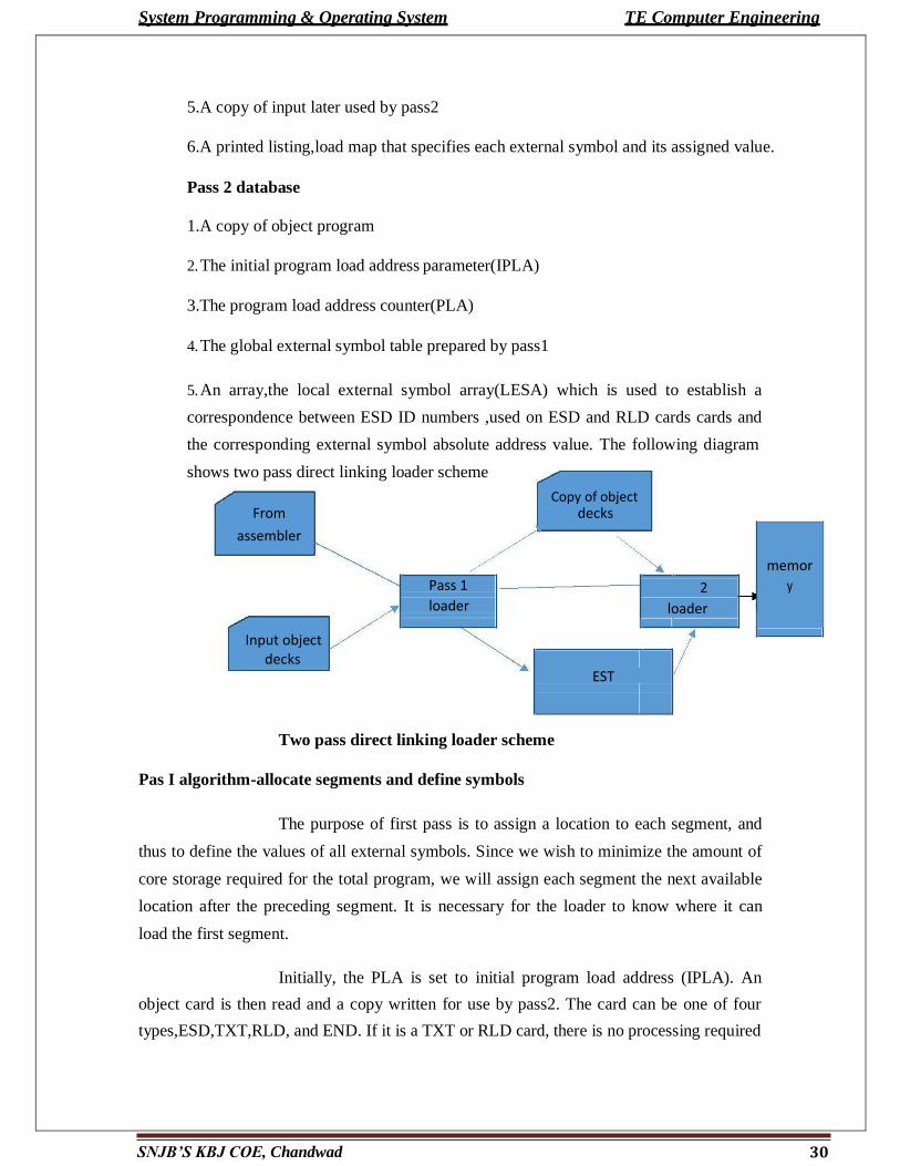
shows two pass direct linking loader scheme
5.A copy of input later used by pass2
6.A printed listing,load map that specifies each external symbol and its assigned value.
Pass 2 database
1.A copy of object program
2. The initial program load address parameter(IPLA)
3.The program load address counter(PLA)
4. The global external symbol table prepared by pass1
5. An array,the local external symbol array(LESA) which is used to establish a
correspondence between ESD ID numbers ,used on ESD and RLD cards cards and
the corresponding external symbol absolute address value. The following diagram
Copy of object
From decks
assembler
memor
Pass 1 2 y
loader loader
Input object
decks
EST
Two pass direct linking loader scheme
Pas I algorithm-allocate segments and define symbols
The purpose of first pass is to assign a location to each segment, and
thus to define the values of all external symbols. Since we wish to minimize the amount of
core storage required for the total program, we will assign each segment the next available
location after the preceding segment. It is necessary for the loader to know where it can
load the first segment.
Initially, the PLA is set to initial program load address (IPLA). An
object card is then read and a copy written for use by pass2. The card can be one of four
types,ESD,TXT,RLD, and END. If it is a TXT or RLD card, there is no processing required
System Programming & Operating System TE Computer Engineering
during pass1 so the next card is read. An ESD card is processed in different ways depending upon the
type of external symbol, SD,LD. If a segment definition ESD card is read, the length field ,
LENGTH from the card is temporarily saved in the variable SLENGTH. The VALUE assigned to
this symbol is set to be current value of PLA. The symbol and its assigned value are then stored in
the GEST. If the symbol already existed in the GEST then error. The symbol and its value are printed
as part of the load map. A similar process is used for LD symbols. The value to be assigned is set to
the current PLA plus the relative address ADDR indicated on the ESD card. The ER symbols do not
require any processing during pass1. When an END card is encountered, the PLA is incremented by
the length of the segment and saved in SLENGTH becoming PLA for the next segment. When an
EOF is finally read, pass 1 is completed and control transfer to pass2.
Pass 2 algorithm-load text and relocate /link address constants
After all the segments have been assigned locations and the external symbols have been defined by
pass 1,it is possible to complete the loading by loading the text and adjusting address constants. At
the end of pass2, the loader will transfer control to the loaded program. At the beginning of pass2,
initialize IPLA. The cards are read and different types of card are processed accordingly.
Pune Vidyarthi Griha’s COLLEGE OF ENGINEERING, NASHIK-4. 31


