
1.2
Undermount Slides
King Slide reserves the right to alter specifications of all the products without notice. If the entity is different from the illustration, please refer to the entity.
1A88
Our 1A88 allows you to utilize your furniture elegantly without any effort.The push-open design will completely change your views about drawers. Without the handle bar your furniture can keep its fine appearance and more stylish look can be achieved. The 1A88 employs our meticulously developed hydraulic dampers to provide long lifespan and better performance. The hydraulic dampers also bring about a smoother and quieter drawer operation. After all, you would no longer be afflicted by squeaky/hard to operate drawers. The 1A88 is the hidden foundation in life that you deserve.
Push-Open with Silent Soft-ClosingUndermount Slide
Pronounced style, classic designWhere simplicity and luxurious lifestyles meet
King Slide flawlessly combined the touch-to-open and soft-closing technologies in 1A88. Unlike other brands, King Slide uses all-mechanical patent pending design that will not only save electricity but also promote green technology. With King Slide’s all-mechanical design, 1A88 concocts your personal style and green life!
The World’s First Electric-Free All-Mechanical Design

1.3
www.kingslide.com
King Slide reserves the right to alter specifications of all the products without notice. If the entity is different from the illustration, please refer to the entity.
Undermount Slides
1
IWF 2010 Challengers Award® Winner
Best of KBIS: Best of Kitchen Gold Award
TAIWAN Excellence 2011
The Kitchen & Bath Industry Show (KBIS) is the world’s largest international trade event that focuses specially on all aspects of kitchens and baths. The winners of the 2010 Best of KBIS Competition announced at the show highlight exceptional products introduced in the past 12 months for their functionality, quality, flexibility, aesthetics, style and innovation.
The IWF Challengers Award® is widely known as the woodworking industry’s highest honor, recognizing advancements in technologies or significant contributions to environmental improvements. The award challenges IWF exhibiting companies to develop revolutionary, ingenious and forward-thinking technologies, materials and safety devices that advance the industry.
Taiwan Excellence is the highest accolade awarded to products that encapsulate innovation. Taiwan Excellence winners represent the most revolutionary, high quality, high value added products/designs made by Taiwan.
A) Press the Drawer Front
A) Press the Drawer Front
Way 1.
Way 2.
B) Drawer Opens Automatically via Mechanism
B) Pull the Drawer for Your Use
C) Press to Close the Drawer
C) Silent Soft-Closing
Operation Manual
Awarded Prizes

1.4
Undermount Slides
King Slide reserves the right to alter specifications of all the products without notice. If the entity is different from the illustration, please refer to the entity.
• Push-open, handle-free.• Enhanced silent soft-closing feature with light opening force• Durable damping system with fast response capability• All mechanical device, instead of electric-driven• Safe, user-friendly and energy saving• Undermount with full extension travel length• Ultra smooth gliding motion with high rigidity and stability
design• Ergonomic trimming system provides tool-less height and
depth adjustments• A tool-less adjustment system is available to permit minor
installation inaccuracies, thereby reducing assemblage complexity.
• Effortless assembly and removal of drawer with front release lever
• High installation allowances for drawer width: +0.5/-1mm, and for drawer depth: +1/-1mm
Push-Open with Silent Soft-Closing
Undermount Slide (16mm)
1A88• Length: 250mm to 550mm• Travel: Full Extension• Maximum Drawer Side Thickness: 16mm• Max. Load Capacity: 34 kg (75 lb) /pair• Mount: Undermount• Material: Galvanized Steel• Packing: Unit Packed in 2 pairs/carton
6 pairs/carton
• For Frameless Cabinet : Kitchen Furniture, Kitchen Cabinetry, Home Cabinetry and Box Drawers
Specifications
Applications
Features
250
300
350
400
450
500
550
3218
32 329
3796192
288
4(max)18
W-42W
+0.5-1.0
min 6
max 16
37
21min 27.5
max 13
W : Internal Cabinet Width
1.5
www.kingslide.com
King Slide reserves the right to alter specifications of all the products without notice. If the entity is different from the illustration, please refer to the entity.
Undermount Slides
1
○ X
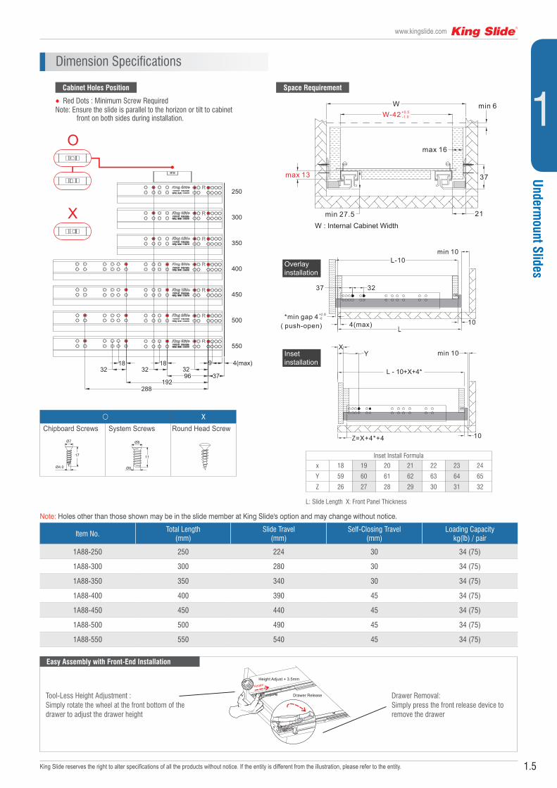
Chipboard Screws System Screws Round Head Screw
Dimension Specifications
Item No.Total Length
(mm)Slide Travel
(mm)Self-Closing Travel
(mm)Loading Capacity
kg(lb) / pair
1A88-250 250 224 30 34 (75)
1A88-300 300 280 30 34 (75)
1A88-350 350 340 30 34 (75)
1A88-400 400 390 45 34 (75)
1A88-450 450 440 45 34 (75)
1A88-500 500 490 45 34 (75)
1A88-550 550 540 45 34 (75)
● Red Dots : Minimum Screw RequiredNote: Ensure the slide is parallel to the horizon or tilt to cabinet
front on both sides during installation.
Tool-Less Height Adjustment : Simply rotate the wheel at the front bottom of the drawer to adjust the drawer height
Drawer Removal:Simply press the front release device to remove the drawer
250
300
350
400
450
500
550
3218
32 329
3796192
288
4(max)18
W-42W
+0.5-1.0
min 6
max 16
37
21min 27.5
max 13
W : Internal Cabinet Width
*min gap 4( push-open)
XY
Z 4=X+4 +*
3237
min 10
min 10
4(max)
L - 10+X+4*
L-10
+2.0-0
10
10
Overlayinstallation
Insetinstallation
Cabinet Holes Position
Easy Assembly with Front-End Installation
Space Requirement
Note: Holes other than those shown may be in the slide member at King Slide's option and may change without notice.
250
300
350
400
450
500
550
3218
32 329
3796192
288
4(max)18
W-42W
+0.5-1.0
min 6
max 16
37
21min 27.5
max 13
W : Internal Cabinet Width
*min gap 4( push-open)
XY
Z 4=X+4 +*
3237
min 10
min 10
4(max)
L - 10+X+4*
L-10
+2.0-0
10
10
Overlayinstallation
Insetinstallation
250
300
350
400
450
500
550
3218
32 329
3796192
288
4(max)18
W-42W
+0.5-1.0
min 6
max 16
37
21min 27.5
max 13
W : Internal Cabinet Width
*min gap 4( push-open)
XY
Z 4=X+4 +*
3237
min 10
min 10
4(max)
L - 10+X+4*
L-10
+2.0-0
10
10
Overlayinstallation
Insetinstallation
Inset Install Formula
x 18 19 20 21 22 23 24
Y 59 60 61 62 63 64 65
Z 26 27 28 29 30 31 32
L: Slide Length X: Front Panel Thickness
1.6
Undermount Slides
King Slide reserves the right to alter specifications of all the products without notice. If the entity is different from the illustration, please refer to the entity.
Push-Open with Silent Soft-Closing Undermount Slide (19mm)
1B88• Length: 250mm to 550mm• Travel: Full Extension• Maximum Drawer Side Thickness: 19mm• Max. Load Capacity: 34 kg (75 lb)/pair• Mount: Undermount• Material: Galvanized Steel• Packing: Unit Packed In 2 pairs/carton
6 pairs/carton
250
300
350
400
450
500
550
3218
32 329
3796192
288
4(max)18
W-49W
+0.5-1.0
min 6
max 19
37
24.5min 27.5
max 13
W : Internal Cabinet Width
• For Frameless Cabinet : Kitchen Furniture, Kitchen Cabinetry, Home Cabinetry and Box Drawers
Specifications
Features
Applications
• Push-open, handle-free
• Enhanced silent soft-closing feature with light opening force
• Durable damping system with fast response capability
• All mechanical device, instead of electric-driven
• Safe, user-friendly and energy saving
• Undermount with full extension travel length
• Ultra smooth gliding motion with high rigidity and stability design
• Ergonomic trimming system provides tool-less height and depth adjustments
• A tool-less adjustment system is available to permit minor installation inaccuracies, thereby reducing assemblage complexity.
• Effortless assembly and removal of drawer with front release lever
• High installation allowances for drawer width: +0.5/-1mm, and for drawer depth: +1/-1mm

1.7
www.kingslide.com
King Slide reserves the right to alter specifications of all the products without notice. If the entity is different from the illustration, please refer to the entity.
Undermount Slides
1Dimension Specifications
250
300
350
400
450
500
550
3218
32 329
3796192
288
4(max)18
W-49W
+0.5-1.0
min 6
max 19
37
24.5min 27.5
max 13
W : Internal Cabinet Width
250
300
350
400
450
500
550
3218
32 329
3796192
288
4(max)18
W-49W
+0.5-1.0
min 6
max 19
37
24.5min 27.5
max 13
W : Internal Cabinet Width
Item No.Total Length
(mm)Slide Travel
(mm)Self-Closing Travel
(mm)Loading Capacity
kg(lb) / pair
1B88-250 250 224 30 34 (75)
1B88-300 300 280 30 34 (75)
1B88-350 350 340 30 34 (75)
1B88-400 400 390 45 34 (75)
1B88-450 450 440 45 34 (75)
1B88-500 500 490 45 34 (75)
1B88-550 550 540 45 34 (75)
○ Chipboard Screws System Screws
XRound Head Screw
● Red Dots : Minimum Screw Required
Note: Ensure the slide is parallel to the horizon or tilt to cabinet front on both sides during installation.
250
300
350
400
450
500
550
3218
32 329
3796192
288
4(max)18
W-49W
+0.5-1.0
min 6
max 19
37
24.5min 27.5
max 13
W : Internal Cabinet Width
Tool-Less Height Adjustment :
Simply rotate the wheel at the front bottom
of the drawer to adjust the drawer height
Drawer Removal:
Simply press the front release device
to remove the drawer
Cabinet Holes Position Space Requirement
Easy Assembly with Front-End Installation
Our specially designed front-end installation allows
quick and simple drawer installation and removal
processes. The quick connect and disconnect
device is located at the front-end under the drawer,
keeping intact the elegant appearance of the drawer.
Note: Holes other than those shown may be in the slide member at King Slide's option and may change without notice.

1.8
Undermount Slides
King Slide reserves the right to alter specifications of all the products without notice. If the entity is different from the illustration, please refer to the entity.
Overlay Drawer Front
Inset Drawer Front
*min gap 4( push-open)
XY
Z 4=X+4 +*
3237
min 10
min 10
4(max)
L - 10+X+4*
L-10
+2.0-0
10
10
Note
Note
Inward
Outward
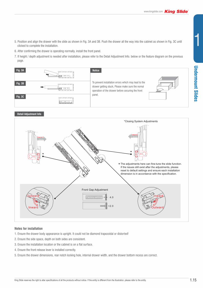
4.0
+2.0
Factory setting
Inward1.0mm
*Closing System Adjustments
Inward1.0mm
Outward
Inward
The adjustments here can fine-tune the slide function.If the issues still exist after the adjustments, please reset to default settings and ensure each installation dimension is in accordance with the specification.
W-49W
+0.5-1.0
min 6
max 19
37
24.5min 27.5
max 13
W : Internal Cabinet Width
W-42W
+0.5-1.0
min 6
max 16
37
21min 27.5
max 13
W : Internal Cabinet Width
Front Gap Adjustment
Overlay Drawer Front
Inset Drawer Front
*min gap 4( push-open)
XY
Z 4=X+4 +*
3237
min 10
min 10
4(max)
L - 10+X+4*
L-10
+2.0-0
10
10
Note
Note
Inward
Outward
4.0
+2.0
Factory setting
Inward1.0mm
*Closing System Adjustments
Inward1.0mm
Outward
Inward
The adjustments here can fine-tune the slide function.If the issues still exist after the adjustments, please reset to default settings and ensure each installation dimension is in accordance with the specification.
W-49W
+0.5-1.0
min 6
max 19
37
24.5min 27.5
max 13
W : Internal Cabinet Width
W-42W
+0.5-1.0
min 6
max 16
37
21min 27.5
max 13
W : Internal Cabinet Width
Front Gap Adjustment
Installation Instruction
1. Before installing the slides, make sure the dimensions of the cabinet and drawer meet the requirements specified in Fig. 1 and Fig. 2.
2. Drill holes on the cabinet following the 'Cabinet Holes Position' drawing on the reverse page. Mount the slides on the cabinet using the recommended type of screws.
3. Make cut-outs on the drawer according to Fig. 3A and Fig. 3B's dimension (Using the drill template FL00ZD0-A as page 1.39 is recommended), then install the front release lever according to Fig. 3A.
4. Pull out the slides on the cabinet.
1A88 & 1B88
Installation Specification
Front ViewDimension Specification
1A88
1B88
Fig. 1
Fig. 3B
Fig. 3A
Overlay Drawer Front
Inset Drawer Front
*min gap 4( push-open)
XY
Z 4=X+4 +*
3237
min 10
min 10
4(max)
L - 10+X+4*
L-10
+2.0-0
10
10
Note
Note
Inward
Outward
4.0
+2.0
Factory setting
Inward1.0mm
*Closing System Adjustments
Inward1.0mm
Outward
Inward
The adjustments here can fine-tune the slide function.If the issues still exist after the adjustments, please reset to default settings and ensure each installation dimension is in accordance with the specification.
W-49W
+0.5-1.0
min 6
max 19
37
24.5min 27.5
max 13
W : Internal Cabinet Width
W-42W
+0.5-1.0
min 6
max 16
37
21min 27.5
max 13
W : Internal Cabinet Width
Front Gap Adjustment
Side ViewFig. 2
Note:
Ensure the slide is parallel to the horizon or tilt to cabinet front on both sides during installation.
Inset Install Formulax 18 19 20 21 22 23 24Y 59 60 61 62 63 64 65Z 26 27 28 29 30 31 32
L: Slide Length X: Front Panel Thickness
You can use optional drill template FL-00ZD0-A as page 1.39

1.9
www.kingslide.com
King Slide reserves the right to alter specifications of all the products without notice. If the entity is different from the illustration, please refer to the entity.
Undermount Slides
1
Overlay Drawer Front
Inset Drawer Front
*min gap 4( push-open)
XY
Z 4=X+4 +*
3237
min 10
min 10
4(max)
L - 10+X+4*
L-10
+2.0-0
10
10
Note
Note
Inward
Outward
4.0
+2.0
Factory setting
Inward1.0mm
*Closing System Adjustments
Inward1.0mm
Outward
Inward
The adjustments here can fine-tune the slide function.If the issues still exist after the adjustments, please reset to default settings and ensure each installation dimension is in accordance with the specification.
W-49W
+0.5-1.0
min 6
max 19
37
24.5min 27.5
max 13
W : Internal Cabinet Width
W-42W
+0.5-1.0
min 6
max 16
37
21min 27.5
max 13
W : Internal Cabinet Width
Front Gap Adjustment
Detail Adjustment Info.
Fig. 4A Notice
Fig. 4B
Fig. 4C
Overlay Drawer Front
Inset Drawer Front
*min gap 4( push-open)
XY
Z 4=X+4 +*
3237
min 10
min 10
4(max)
L - 10+X+4*
L-10
+2.0-0
10
10
Note
Note
Inward
Outward
4.0
+2.0
Factory setting
Inward1.0mm
*Closing System Adjustments
Inward1.0mm
Outward
Inward
The adjustments here can fine-tune the slide function.If the issues still exist after the adjustments, please reset to default settings and ensure each installation dimension is in accordance with the specification.
W-49W
+0.5-1.0
min 6
max 19
37
24.5min 27.5
max 13
W : Internal Cabinet Width
W-42W
+0.5-1.0
min 6
max 16
37
21min 27.5
max 13
W : Internal Cabinet Width
Front Gap Adjustment
To prevent installation errors which may lead to the drawer getting stuck, please make sure the nomal operation of the drawer before securing the front panel.
5. Position and align the drawer with the slide as shown in Figs. 4A and 4B. Push the drawer all the way into the cabinet as shown in Fig. 4C until clicked to complete the installation.
6. After confirming the drawer is operating normally, install the front panel.
7. If height / depth adjustment is needed after installation, please refer to the Detail Adjustment Info. below or the feature diagram on the previous page.
Notes for installation1. Ensure the drawer body appearance is upright. It could not be diamond trapezoidal or distorted!
2. Ensure the side space, depth on both sides are consistent.
3. Ensure the installation location or the cabinet is on a flat surface.
4. Ensure the front release lever is installed correctly.
5. Ensure the drawer dimensions, rear notch locking hole, internal drawer width, and the drawer bottom recess are correct.
1.12
Undermount Slides
King Slide reserves the right to alter specifications of all the products without notice. If the entity is different from the illustration, please refer to the entity.
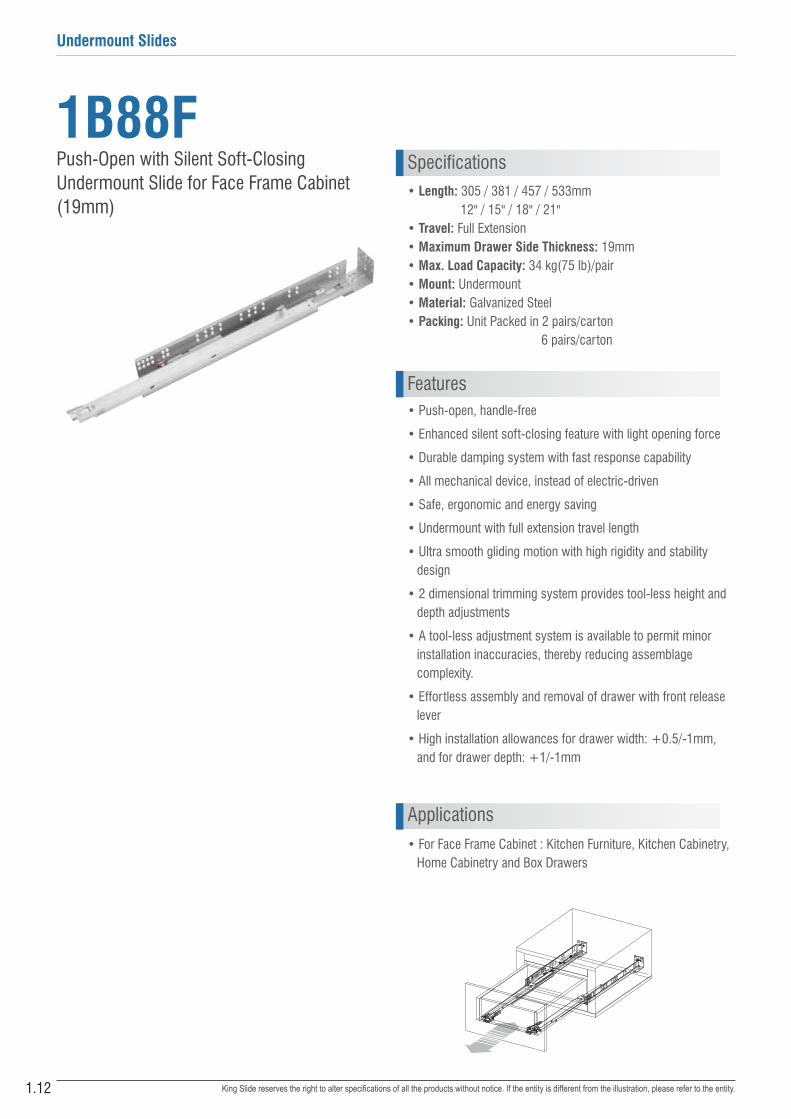
• Push-open, handle-free
• Enhanced silent soft-closing feature with light opening force
• Durable damping system with fast response capability
• All mechanical device, instead of electric-driven
• Safe, ergonomic and energy saving
• Undermount with full extension travel length
• Ultra smooth gliding motion with high rigidity and stability design
• 2 dimensional trimming system provides tool-less height and depth adjustments
• A tool-less adjustment system is available to permit minor installation inaccuracies, thereby reducing assemblage complexity.
• Effortless assembly and removal of drawer with front release lever
• High installation allowances for drawer width: +0.5/-1mm, and for drawer depth: +1/-1mm
1B88F• Length: 305 / 381 / 457 / 533mm 12" / 15" / 18" / 21"• Travel: Full Extension• Maximum Drawer Side Thickness: 19mm• Max. Load Capacity: 34 kg(75 lb)/pair• Mount: Undermount• Material: Galvanized Steel• Packing: Unit Packed in 2 pairs/carton
6 pairs/carton
Push-Open with Silent Soft-Closing Undermount Slide for Face Frame Cabinet (19mm)
Profile Length
Cabinet Depth with Bracket
A
B
Drawer Length
bracket
37(1-7/16”)9(11/32”)
4(5/32")max
**4min gap
(push-open)
10(3/8”)
X
+2.0
-0
Note
W
W - 42+0.5-1.0
Drawer Side ThicknessMaximum 16mm(5/8'')
min 6
37(1-7/16")
21(13/16")min 27.5
max
13m
m (
1/2”
)
13(1/2")
open
ing
Dra
wer
Hei
ght
Max
= o
peni
ng -
24m
m(1
5/16
”)
Drawer Width
Specifications
Features
Applications• For Face Frame Cabinet : Kitchen Furniture, Kitchen Cabinetry,
Home Cabinetry and Box Drawers

1.13
www.kingslide.com
King Slide reserves the right to alter specifications of all the products without notice. If the entity is different from the illustration, please refer to the entity.
Undermount Slides
1
Profile Length
Cabinet Depth with Bracket
A
B
Drawer Length
bracket
37(1-7/16”)9(11/32”)
4(5/32")max
**4min gap
(push-open)
10(3/8”)
X
+2.0
-0
Note
Drawer Slide ThicknessMaximum 19 (3/4'')
Item No.Drawer Length
mm (inch)Overall Cabinet Depth
mm (inch)
Cabinet Depth With Bracketmm (inch) Profile Length
mm (inch)
System Screw Locationsmm (inch)
MAX MIN A B
1B88F305 305 (12") 381 (15") 369 (14-9/16") 326 (12-7/8") 318 (12-1/2") 165 (6-1/2") 261 (10-1/4")
1B88F381 381 (15") 457 (18") 446 (17-9/16") 403 (15-7/8") 394 (15-1/2") 165 (6-1/2") 357 (14-1/16")
1B88F457 457 (18") 533 (21") 522 (20-9/16") 479 (18-7/8") 470 (18-1/2") 261 (10-1/4") 453 (17-13/16")
1B88F533 533 (21") 610 (24") 598 (23-9/16") 555 (21-7/8") 546 (21-1/2") 261 (10-1/4") 517 (20-3/8")
Fit with American standard 3" cabinet depth system.
Dimension Specifications
Space Requirement
Drawer Removal:
Simply press the front release device to remove
the drawer
Our specially designed front-end installation allows
quick and simple drawer installation and removal
processes. The quick connect and disconnect
device is located at the front-end under the drawer,
keeping intact the elegant appearance of the drawer.
250
300
350
400
450
500
550
3218
32 329
3796192
288
4(max)18
W-42W
+0.5-1.0
min 6
max 16
37
21min 27.5
max 13
W : Internal Cabinet Width
Tool-less Height Adjustment :
Simply rotate the wheel at the front bottom of the drawer
to adjust the drawer height
Drawer Width Formula
Drawer Side Thicknessmm (inch)
"W" minusmm (inch)
19 (3/4") 11 (7/16")
18 (23/32") 13 (1/2")
17 (21/31") 15 (19/32")
16 (5/8") 17 (21/32")
15 (19/32") 19 (3/4")
W: Internal Cabinet Width
Example:
Internal Cabinet Width = 457 mm (18")
Drawer Side Thickness = 19 mm (3/4")
Drawer width = 457 - 11 = 446 mm
= (18") - (7/16") = 17-9/16"
+0.5-1.0
Note:Ensure the slide is parallel to the horizon or tilt to cabinet front on both sides during installation.
Profile Length
Cabinet Depth with Bracket
A
B
Drawer Length
bracket
37(1-7/16”)9(11/32”)
4(5/32")max
**4min gap
(push-open)
10(3/8”)
X
+2.0
-0
Note
Drawer Slide ThicknessMaximum 19 (3/4'')
○ Chipboard Screw System Screw
X Round Heard Screw
Easy Assembly with Front-End Installation
Note: Holes other than those shown may be in the slide member at King Slide's option and may change without notice.

1.14
Undermount Slides
King Slide reserves the right to alter specifications of all the products without notice. If the entity is different from the illustration, please refer to the entity.
X
Z (setback) = (X +**4) + 4(max)Min = L + Z + 5(3/16")Max = L + Z + 48(1-15/16")
Blocking Behind FrameY
bracket
◎Slide bottom can not be lower than opening
Cabinet Depth
Drawer Length
B racket
37(1-7/16”)
4(5/32")max
**4min gap
(push-open)
10(3/8”)
X
+2.0
-00
Normal lnstall
Inset lnstall
Note
Note
Inward
Outward
4.0
+2.0
Factory setting
*
Inward1.0mm
*Closing System Adjustments
Inward1.0mm
*
*
Outward
Inward
The adjustments here can fine-tune the slide function.If the issues still exist after the adjustments, please reset to default settings and ensure each installation dimension is in accordance with the specification.
rear notch33(1-5 /16″)
7(9/32″)
11(7/16″)
Ø6*10
XO
Locking Device
Locking Device with Extension Plastic
Extension Plastic
*Minimum 3 screws per bracket
21(13/16")
(15/32")(9/16")1214
32(1-1/4'')
16(5/8'')
2(3/32'')
Front Gap Adjustment
Profile Length
Installation Instruction
1. Before installing the slides, make sure the dimensions of the cabinet and drawer meet the requirements specified in Fig. 1 and ' Space Requirement' drawing resectively for the slide to be installed.
2. Drill holes on the cabinet following the 'Installating Specification' drawing on the reverse page. Mount the slides and the rear brackets on the cabinet using the recommended type of screws.
3. Make cut-outs on the drawer according to Fig. 2A 's dimension (Using the drill template FL00ZD0-A as page 1.39 is recommended) , then install the front release lever according to Fig. 2B and 2C.
4. Pull out the slides on the cabinet.
1A88F & 1B88F
Installation Requirement
Rear Bracket
Front ViewDimension Specification
X
Z (setback) = (X +**4) + 4(max)Min = L + Z + 5(3/16")Max = L + Z + 48(1-15/16")
Blocking Behind FrameY
bracket
◎Slide bottom can not be lower than opening
Cabinet Depth
Drawer Length
B racket
37(1-7/16”)
4(5/32")max
**4min gap
(push-open)
10(3/8”)
X
+2.0
-00
Normal lnstall
Inset lnstall
Note
Note
Inward
Outward
4.0
+2.0
Factory setting
*
Inward1.0mm
*Closing System Adjustments
Inward1.0mm
*
*
Outward
Inward
The adjustments here can fine-tune the slide function.If the issues still exist after the adjustments, please reset to default settings and ensure each installation dimension is in accordance with the specification.
rear notch33(1-13/16″)
7(9/32″)
11(7/16″)
Ø6*10
XO
Locking Device
Locking Device with Extension Plastic
Extension Plastic
*Minimum 3 screws per bracket
21(13/16")
(15/32")(9/16")1214
32(1-1/4'')
16(5/8'')
2(3/32'')
Front Gap Adjustment
Profile Length
Fig. 1
Fig. 2A
Fig. 2C
Fig. 2B
Inset Install Formulax 16 17 18 19 20 21 22Y 57 58 59 60 61 62 63Z 24 25 26 27 28 29 30
L: Slide Length X: Front Panel Thickness
Note:
Ensure the slide is parallel to the horizon
or tilt to cabinet front on both sides during
installation.
You can use optional drill template
FL-00ZD0-A as page 1.39
X
Z (setback) = (X +**4) + 4(max)Min = L + Z + 5(3/16")Max = L + Z + 48(1-15/16")
Blocking Behind FrameY
bracket
◎Slide bottom can not be lower than opening
Cabinet Depth
Drawer Length
B racket
37(1-7/16”)
4(5/32")max
**4min gap
(push-open)
10(3/8”)
X
+2.0
-00
Normal lnstall
Inset lnstall
Note
Note
Inward
Outward
4.0
+2.0
Factory setting
*
Inward1.0mm
*Closing System Adjustments
Inward1.0mm
*
*
Outward
Inward
The adjustments here can fine-tune the slide function.If the issues still exist after the adjustments, please reset to default settings and ensure each installation dimension is in accordance with the specification.
rear notch33(1-13/16″)
7(9/32″)
11(7/16″)
Ø6*10
XO
Locking Device
Locking Device with Extension Plastic
Extension Plastic
*Minimum 3 screws per bracket
21(13/16")
(15/32")(9/16")1214
32(1-1/4'')
16(5/8'')
2(3/32'')
Front Gap Adjustment
Profile Length
1.15
www.kingslide.com
King Slide reserves the right to alter specifications of all the products without notice. If the entity is different from the illustration, please refer to the entity.
Undermount Slides
15. Position and align the drawer with the slide as shown in Fig. 3A and 3B. Push the drawer all the way into the cabinet as shown in Fig. 3C until clicked to complete the installation.
6. After confirming the drawer is operating normally, install the front panel.
7. If height / depth adjustment is needed after installation, please refer to the Detail Adjustment Info. below or the feature diagram on the previous page.
X
Z (setback) = (X +**4) + 4(max)Min = L + Z + 5(3/16")Max = L + Z + 48(1-15/16")
Blocking Behind FrameY
bracket
◎Slide bottom can not be lower than opening
Cabinet Depth
Drawer Length
B racket
37(1-7/16”)
4(5/32")max
**4min gap
(push-open)
10(3/8”)
X
+2.0
-00
Normal lnstall
Inset lnstall
Note
Note
Inward
Outward
4.0
+2.0
Factory setting
*
Inward1.0mm
*Closing System Adjustments
Inward1.0mm
*
*
Outward
Inward
The adjustments here can fine-tune the slide function.If the issues still exist after the adjustments, please reset to default settings and ensure each installation dimension is in accordance with the specification.
rear notch33(1-13/16″)
7(9/32″)
11(7/16″)
Ø6*10
XO
Locking Device
Locking Device with Extension Plastic
Extension Plastic
*Minimum 3 screws per bracket
21(13/16")
(15/32")(9/16")1214
32(1-1/4'')
16(5/8'')
2(3/32'')
Front Gap Adjustment
Profile Length
Detail Adjustment Info
X
Z (setback) = (X +**4) + 4(max)Min = L + Z + 5(3/16")Max = L + Z + 48(1-15/16")
Blocking Behind FrameY
bracket
◎Slide bottom can not be lower than opening
Cabinet Depth
Drawer Length
B racket
37(1-7/16”)
4(5/32")max
**4min gap
(push-open)
10(3/8”)
X
+2.0
-00
Normal lnstall
Inset lnstall
Note
Note
Inward
Outward
4.0
+2.0
Factory setting
*
Inward1.0mm
*Closing System Adjustments
Inward1.0mm
*
*
Outward
Inward
The adjustments here can fine-tune the slide function.If the issues still exist after the adjustments, please reset to default settings and ensure each installation dimension is in accordance with the specification.
rear notch33(1-13/16″)
7(9/32″)
11(7/16″)
Ø6*10
XO
Locking Device
Locking Device with Extension Plastic
Extension Plastic
*Minimum 3 screws per bracket
21(13/16")
(15/32")(9/16")1214
32(1-1/4'')
16(5/8'')
2(3/32'')
Front Gap Adjustment
Profile Length
Fig. 3A
Fig. 3B
Fig. 3C
X
Z (setback) = (X +**4) + 4(max)Min = L + Z + 5(3/16")Max = L + Z + 48(1-15/16")
Blocking Behind FrameY
bracket
◎Slide bottom can not be lower than opening
Cabinet Depth
Drawer Length
B racket
37(1-7/16”)
4(5/32")max
**4min gap
(push-open)
10(3/8”)
X
+2.0
-00
Normal lnstall
Inset lnstall
Note
Note
Inward
Outward
4.0
+2.0
Factory setting
*
Inward1.0mm
*Closing System Adjustments
Inward1.0mm
*
*
Outward
Inward
The adjustments here can fine-tune the slide function.If the issues still exist after the adjustments, please reset to default settings and ensure each installation dimension is in accordance with the specification.
rear notch33(1-13/16″)
7(9/32″)
11(7/16″)
Ø6*10
XO
Locking Device
Locking Device with Extension Plastic
Extension Plastic
*Minimum 3 screws per bracket
21(13/16")
(15/32")(9/16")1214
32(1-1/4'')
16(5/8'')
2(3/32'')
Front Gap Adjustment
Profile Length
X
Z (setback) = (X +**4) + 4(max)Min = L + Z + 5(3/16")Max = L + Z + 48(1-15/16")
Blocking Behind FrameY
bracket
◎Slide bottom can not be lower than opening
Cabinet Depth
Drawer Length
B racket
37(1-7/16”)
4(5/32")max
**4min gap
(push-open)
10(3/8”)
X
+2.0
-00
Normal lnstall
Inset lnstall
Note
Note
Inward
Outward
4.0
+2.0
Factory setting
*
Inward1.0mm
*Closing System Adjustments
Inward1.0mm
*
*
Outward
Inward
The adjustments here can fine-tune the slide function.If the issues still exist after the adjustments, please reset to default settings and ensure each installation dimension is in accordance with the specification.
rear notch33(1-13/16″)
7(9/32″)
11(7/16″)
Ø6*10
XO
Locking Device
Locking Device with Extension Plastic
Extension Plastic
*Minimum 3 screws per bracket
21(13/16")
(15/32")(9/16")1214
32(1-1/4'')
16(5/8'')
2(3/32'')
Front Gap Adjustment
Profile Length
To prevent installation errors which may lead to the
drawer getting stuck, Please make sure the nomal
operation of the drawer before securing the front
panel.
Notes for installation1. Ensure the drawer body appearance is upright. It could not be diamond trapezoidal or distorted!
2. Ensure the side space, depth on both sides are consistent.
3. Ensure the installation location or the cabinet is on a flat surface.
4. Ensure the front release lever is installed correctly.
5. Ensure the drawer dimensions, rear notch locking hole, internal drawer width, and the drawer bottom recess are correct.
Notice


