www.murata-ps.com
www.murata-ps.com/support
For full details go towww.murata-ps.com/rohs
UEI15 SeriesIsolated Wide Input Range 15-Watt DC/DC Converters
MDC_UEI15W.C14 Page 1 of 17
Featuring a full 15 Watt or greater output in one square inch of board area, the UEI series isolated DC/DC converter family offers effi cient regulated DC power for printed circuit board mounting.
GATE DRIVEControl
Reference, Trim & Error Amplifier
+VIN
−VIN
+VOUT
–VOUT
On/OffControl
TRIM
ISOLATION BARRIER
ISOLATION
Typical topology is shown.Figure 1. Simplifi ed block diagram—3.3V and 5VOUT models only.
Typical unit
FEATURESSmall footprint DC/DC converter, ideal for high current applications
Industry standard 0.96" x 1.1" X 0.32" open frame package and pinout
Wide range input voltages 9-36 and 18-75 Vdc
Assembly and attachment for RoHS standards
Isolation up to 2250 VDC (basic)
Up to 15 Watts or greater total output power with overtemperature shutdown
High effi ciency synchronous rectifi er forward topology
Stable operation with no required external components
Usable -40 to 85°C temperature range (with derating)
Certifi ed to UL 60950-1, CAN/CSA-C22.2 No. 60950-1, IEC60950-1, EN60950-1 safety ap-provals, 2nd edition
Extensive self-protection shut down features
PRODUCT OVERVIEWWide range 4:1 inputs on the 0.96" x 1.1" x 0.32" converter are either 9 to 36 Volts DC (Q12 models) or 18 to 75 Volts DC (Q48 models), ideal for battery-powered and telecom equipment. The industry-standard pinout fi ts larger 1" x 2" converters. Fixed output voltages from 3.3 VDC to 15 VDC are regu-lated to within ±0.2% or less and may be trimmed within ±10% of nominal output. Applications include small instruments, area-limited microcon-trollers, computer-based systems, data communi-cations equipment, remote sensor systems, vehicle and portable electronics.
The UEI 15W series includes full magnetic and optical isolation up to 2250 Volts DC (basic insula-tion). For connection to digital systems, the outputs offer fast settling to current step loads and toler-ance of higher capacitive loads. Excellent ripple
and noise specifi cations assure compatibility to circuits using CPU’s, ASIC’s, programmable logic and FPGA’s. For systems requiring controlled startup/shutdown, an external switch, transis-tor or digital logic may be used to activate the remote On/Off control.
A wealth of self-protection features avoid both converter and external circuit problems. These include input undervoltage lockout and overtem-perature shutdown. The outputs current limit using the “hiccup” autorestart technique and the outputs may be short-circuited indefi nitely. Additional features include output overvoltage and reverse conduction elimination.
The high effi ciency offers minimal heat buildup and “no fan” operation.
REG.-Nr. D806
PART NUMBER STRUCTURE
www.murata-ps.com/support
UEI15 SeriesIsolated Wide Input Range 15-Watt DC/DC Converters
MDC_UEI15W.C14 Page 2 of 17
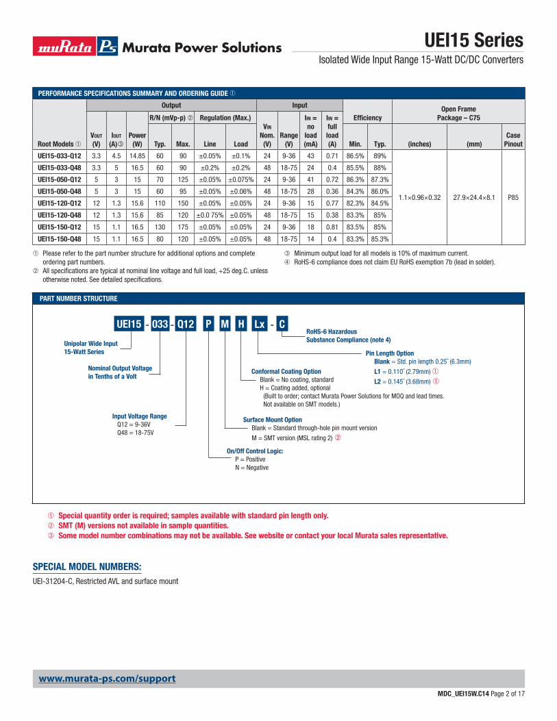
➀ Please refer to the part number structure for additional options and complete ordering part numbers.
➁ All specifi cations are typical at nominal line voltage and full load, +25 deg.C. unless otherwise noted. See detailed specifi cations.
➂ Minimum output load for all models is 10% of maximum current.➃ RoHS-6 compliance does not claim EU RoHS exemption 7b (lead in solder).
PERFORMANCE SPECIFICATIONS SUMMARY AND ORDERING GUIDE ➀
Root Models ➀
Output Input
Effi ciencyOpen Frame
Package – C75
VOUT
(V)IOUT
(A)Power
(W)
R/N (mVp-p) ➁ Regulation (Max.)VIN
Nom.(V)
Range(V)
IIN = no
load(mA)
IIN = full load(A)Typ. Max. Line Load Min. Typ. (inches) (mm)
Case Pinout
UEI15-033-Q12 3.3 4.5 14.85 60 90 ±0.05% ±0.1% 24 9-36 43 0.71 86.5% 89%
1.1×0.96×0.32 27.9×24.4×8.1 P85
UEI15-033-Q48 3.3 5 16.5 60 90 ±0.2% ±0.2% 48 18-75 24 0.4 85.5% 88%
UEI15-050-Q12 5 3 15 70 125 ±0.05% ±0.075% 24 9-36 41 0.72 86.3% 87.3%
UEI15-050-Q48 5 3 15 60 95 ±0.05% ±0.06% 48 18-75 28 0.36 84.3% 86.0%
UEI15-120-Q12 12 1.3 15.6 110 150 ±0.05% ±0.05% 24 9-36 15 0.77 82.3% 84.5%
UEI15-120-Q48 12 1.3 15.6 85 120 ±0.0 75% ±0.05% 48 18-75 15 0.38 83.3% 85%
UEI15-150-Q12 15 1.1 16.5 130 175 ±0.05% ±0.05% 24 9-36 18 0.81 83.5% 85%
UEI15-150-Q48 15 1.1 16.5 80 120 ±0.05% ±0.05% 48 18-75 14 0.4 83.3% 85.3%
Nominal Output Voltagein Tenths of a Volt
Unipolar Wide Input15-Watt Series
UEI15 - Q12- -033 P M
On/Off Control Logic: P = Positive N = Negative
Surface Mount Option Blank = Standard through-hole pin mount version
M = SMT version (MSL rating 2) ➁
CRoHS-6 HazardousSubstance Compliance (note 4)
Input Voltage Range Q12 = 9-36V Q48 = 18-75V
Lx
Pin Length Option Blank = Std. pin length 0.25˝ (6.3mm)
L1 = 0.110˝ (2.79mm) ➀
L2 = 0.145˝ (3.68mm) ➀
SPECIAL MODEL NUMBERS:UEI-31204-C, Restricted AVL and surface mount
H
Conformal Coating Option Blank = No coating, standard H = Coating added, optional (Built to order; contact Murata Power Solutions for MOQ and lead times. Not available on SMT models.)
➀ Special quantity order is required; samples available with standard pin length only.➁ SMT (M) versions not available in sample quantities.➂ Some model number combinations may not be available. See website or contact your local Murata sales representative.
www.murata-ps.com/support
UEI15 SeriesIsolated Wide Input Range 15-Watt DC/DC Converters
MDC_UEI15W.C14 Page 3 of 17
Remove overload for recovery.
MISCELLANEOUS CHARACTERISTICS
Model Family
Current Limit Inception 98% of
Vout, after warmupA
Short Circuit
Protection Method
Short Circuit Current
A
Short Circuit Duration
(output shorted to ground)➀
Pre-biased setup
Calculated MTBF
Hours ➃
Operating Temperature Range Storage Temperature
RangeºC
Thermal protection/shutdown
ºC
See DeratingCurves
UEI15-033-Q12 6.0
Current limiting, hiccup
autorestart
0.3 Continuous Monotonic
2 x 10⁶
–40 to +85ºC –55 to +125 ºC
115
UEI15-033-Q48 7.2 3.49 x 10⁶
UEI15-050-Q12 4.6
2 x 10⁶UEI15-050-Q48 4.5
UEI15-120-Q12 2.0
UEI15-120-Q48 1.8 4.1 x 10⁶ 135
UEI15-150-Q12 1.6 2.1 x 10⁶
115UEI15-150-Q48 1.7 2 x 10⁶
17
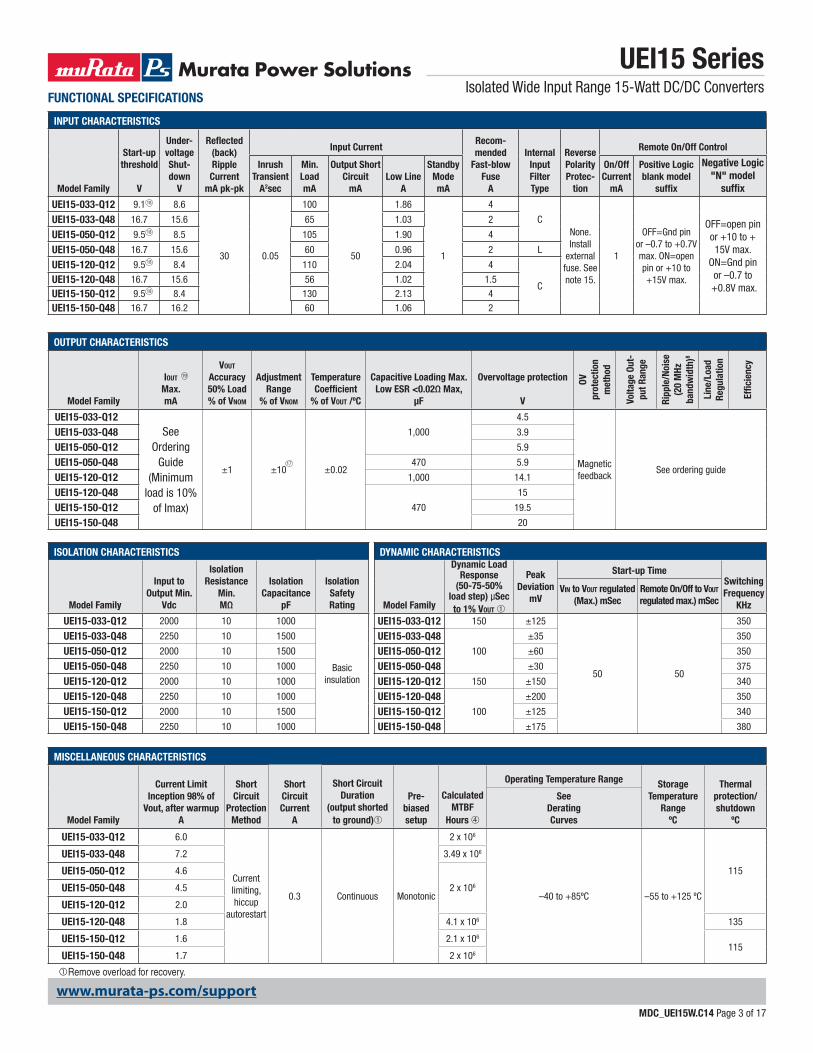
INPUT CHARACTERISTICS
Model Family
Start-up threshold
V
Under-voltage Shut-down
V
Refl ected (back) RippleCurrent
mA pk-pk
Input CurrentRecom-mended
Fast-blow Fuse
A
Internal Input Filter Type
Reverse Polarity Protec-
tion
Remote On/Off Control
Inrush Transient
A2sec
Min. LoadmA
Output Short Circuit
mALow Line
A
Standby ModemA
On/Off Current
mA
Positive Logicblank model
suffi x
Negative Logic"N" model
suffi x
UEI15-033-Q12 9.1 8.6
30 0.05
100
50
1.86
1
4
CNone. Install
external fuse. See note 15.
1
OFF=Gnd pinor –0.7 to +0.7V max. ON=openpin or +10 to +15V max.
OFF=open pinor +10 to +15V max.
ON=Gnd pin or –0.7 to
+0.8V max.
UEI15-033-Q48 16.7 15.6 65 1.03 2
UEI15-050-Q12 9.5 8.5 105 1.90 4
UEI15-050-Q48 16.7 15.6 60 0.96 2 L
UEI15-120-Q12 9.5 8.4 110 2.04 4
CUEI15-120-Q48 16.7 15.6 56 1.02 1.5
UEI15-150-Q12 9.5 8.4 130 2.13 4
UEI15-150-Q48 16.7 16.2 60 1.06 2
OUTPUT CHARACTERISTICS
Model Family
IOUT
Max.mA
VOUT Accuracy50% Load% of VNOM
Adjustment Range
% of VNOM
Temperature Coeffi cient
% of VOUT /ºC
Capacitive Loading Max.Low ESR <0.02Ω Max,
μF
Overvoltage protection
V
OV
prot
ectio
n m
etho
d
Volta
ge O
ut-
put R
ange
Ripp
le/N
oise
(20
MHz
ba
ndw
idth
)8
Line
/Loa
d Re
gula
tion
Effi c
ienc
y
UEI15-033-Q12See
OrderingGuide
(Minimum load is 10%
of Imax)
±1 ±10 ±0.02
1,000
4.5
Magnetic feedback
See ordering guide
UEI15-033-Q48 3.9
UEI15-050-Q12 5.9
UEI15-050-Q48 470 5.9
UEI15-120-Q12 1,000 14.1
UEI15-120-Q48470
15
UEI15-150-Q12 19.5
UEI15-150-Q48 20
ISOLATION CHARACTERISTICS
Model Family
Input to Output Min.
Vdc
Isolation Resistance
Min.MΩ
Isolation Capacitance
pF
Isolation Safety Rating
UEI15-033-Q12 2000 10 1000
Basic insulation
UEI15-033-Q48 2250 10 1500
UEI15-050-Q12 2000 10 1500
UEI15-050-Q48 2250 10 1000
UEI15-120-Q12 2000 10 1000
UEI15-120-Q48 2250 10 1000
UEI15-150-Q12 2000 10 1500
UEI15-150-Q48 2250 10 1000
18
18
18
18
19
FUNCTIONAL SPECIFICATIONS
DYNAMIC CHARACTERISTICS
Model Family
Dynamic Load Response
(50-75-50% load step) μSec to 1% VOUT ➀
PeakDeviation
mV
Start-up TimeSwitching Frequency
KHz
VIN to VOUT regulated (Max.) mSec
Remote On/Off to VOUT regulated max.) mSec
UEI15-033-Q12 150 ±125
50 50
350
UEI15-033-Q48100
±35 350
UEI15-050-Q12 ±60 350
UEI15-050-Q48 ±30 375
UEI15-120-Q12 150 ±150 340
UEI15-120-Q48100
±200 350
UEI15-150-Q12 ±125 340
UEI15-150-Q48 ±175 380
www.murata-ps.com/support
UEI15 SeriesIsolated Wide Input Range 15-Watt DC/DC Converters
MDC_UEI15W.C14 Page 4 of 17
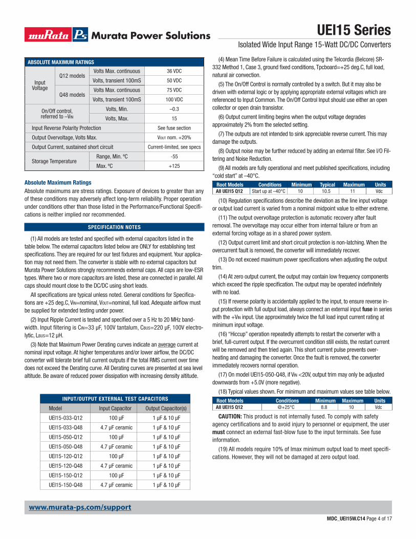
Absolute Maximum RatingsAbsolute maximums are stress ratings. Exposure of devices to greater than any of these conditions may adversely affect long-term reliability. Proper operation under conditions other than those listed in the Performance/Functional Specifi -cations is neither implied nor recommended.
(4) Mean Time Before Failure is calculated using the Telcordia (Belcore) SR-332 Method 1, Case 3, ground fi xed conditions, Tpcboard=+25 deg.C, full load, natural air convection.
(5) The On/Off Control is normally controlled by a switch. But it may also be driven with external logic or by applying appropriate external voltages which are referenced to Input Common. The On/Off Control Input should use either an open collector or open drain transistor.
(6) Output current limiting begins when the output voltage degrades approximately 2% from the selected setting.
(7) The outputs are not intended to sink appreciable reverse current. This may damage the outputs.
(8) Output noise may be further reduced by adding an external fi lter. See I/O Fil-tering and Noise Reduction.
(9) All models are fully operational and meet published specifi cations, including “cold start” at –40°C.
(10) Regulation specifi cations describe the deviation as the line input voltage or output load current is varied from a nominal midpoint value to either extreme.
(11) The output overvoltage protection is automatic recovery after fault removal. The overvoltage may occur either from internal failure or from an external forcing voltage as in a shared power system.
(12) Output current limit and short circuit protection is non-latching. When the overcurrent fault is removed, the converter will immediately recover.
(13) Do not exceed maximum power specifi cations when adjusting the output trim.
(14) At zero output current, the output may contain low frequency components which exceed the ripple specifi cation. The output may be operated indefi nitely with no load.
(15) If reverse polarity is accidentally applied to the input, to ensure reverse in-put protection with full output load, always connect an external input fuse in series with the +VIN input. Use approximately twice the full load input current rating at minimum input voltage.
(16) “Hiccup” operation repeatedly attempts to restart the converter with a brief, full-current output. If the overcurrent condition still exists, the restart current will be removed and then tried again. This short current pulse prevents over-heating and damaging the converter. Once the fault is removed, the converter immediately recovers normal operation.
(17) On model UEI15-050-Q48, if VIN <20V, output trim may only be adjusted downwards from +5.0V (more negative).
(18) Typical values shown. For minimum and maximum values see table below.
CAUTION: This product is not internally fused. To comply with safety agency certifi cations and to avoid injury to personnel or equipment, the user must connect an external fast-blow fuse to the input terminals. See fuse information.
(19) All models require 10% of Imax minimum output load to meet specifi -cations. However, they will not be damaged at zero output load.
SPECIFICATION NOTES
(1) All models are tested and specifi ed with external capacitors listed in the table below. The external capacitors listed below are ONLY for establishing test specifi cations. They are required for our test fi xtures and equipment. Your applica-tion may not need them. The converter is stable with no external capacitors but Murata Power Solutions strongly recommends external caps. All caps are low-ESR types. Where two or more capacitors are listed, these are connected in parallel. All caps should mount close to the DC/DC using short leads.
All specifi cations are typical unless noted. General conditions for Specifi ca-tions are +25 deg.C, VIN=nominal, VOUT=nominal, full load. Adequate airfl ow must be supplied for extended testing under power.
(2) Input Ripple Current is tested and specifi ed over a 5 Hz to 20 MHz band-width. Input fi ltering is CIN=33 μF, 100V tantalum, CBUS=220 μF, 100V electro-lytic, LBUS=12 μH.
(3) Note that Maximum Power Derating curves indicate an average current at nominal input voltage. At higher temperatures and/or lower airfl ow, the DC/DC converter will tolerate brief full current outputs if the total RMS current over time does not exceed the Derating curve. All Derating curves are presented at sea level altitude. Be aware of reduced power dissipation with increasing density altitude.
ABSOLUTE MAXIMUM RATINGS
Input Voltage
Q12 modelsVolts Max. continuous 36 VDC
Volts, transient 100mS 50 VDC
Q48 modelsVolts Max. continuous 75 VDC
Volts, transient 100mS 100 VDC
On/Off control, referred to –VIN
Volts, Min. –0.3
Volts, Max. 15
Input Reverse Polarity Protection See fuse section
Output Overvoltage, Volts Max. VOUT nom. +20%
Output Current, sustained short circuit Current-limited, see specs
Storage Temperature Range, Min. ºC -55
Max. ºC +125
INPUT/OUTPUT EXTERNAL TEST CAPACITORS
Model Input Capacitor Output Capacitor(s)
UEI15-033-Q12 100 μF 1 μF & 10 μF
UEI15-033-Q48 4.7 μF ceramic 1 μF & 10 μF
UEI15-050-Q12 100 μF 1 μF & 10 μF
UEI15-050-Q48 4.7 μF ceramic 1 μF & 10 μF
UEI15-120-Q12 100 μF 1 μF & 10 μF
UEI15-120-Q48 4.7 μF ceramic 1 μF & 10 μF
UEI15-150-Q12 100 μF 1 μF & 10 μF
UEI15-150-Q48 4.7 μF ceramic 1 μF & 10 μF
Root Models Conditions Minimum Typical Maximum UnitsAll UEI15 Q12 Start up at –40°C 10 10.5 11 Vdc
Root Models Conditions Minimum Maximum UnitsAll UEI15 Q12 @+25°C 8.8 10 Vdc
www.murata-ps.com/support
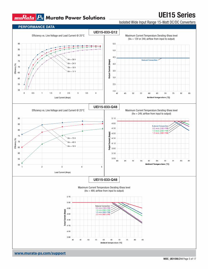
PERFORMANCE DATA
UEI15 SeriesIsolated Wide Input Range 15-Watt DC/DC Converters
MDC_UEI15W.C14 Page 5 of 17
Maximum Current Temperature Derating @sea level(VIN = 24V, airfl ow from input to output)
Maximum Current Temperature Derating @sea level(VIN = 48V, airfl ow from input to output)
Maximum Current Temperature Derating @sea level(VIN = 12V or 24V, airfl ow from input to output)
3.50
3.70
3.90
4.10
4.30
4.50
4.70
4.90
5.10
40 45 50 55 60 65 70 75 80 85
AmAA bient Temperature (°C)
Outp
utCu
rren
t (Am
ps)
Natural Convectionaa0.5 m/s (100 LFM)1.0 m/s (200 LFM)
(1.5 m/s (300 LF )M)
3.80
4.00
4.20
4.40
4.60
4.80
5.00
5.20
40 45 50 55 60 65 70 75 80 85
AmAA bient temperature (°C)
Outp
utCu
rren
t (A((
mps
)
Natural Convectionaa0.5 m/s (100 LFM)1.0 m/s (200 LFM)1.5 m/s (300 LFM)
(2.0 m/s (400 LF )M)
2.0
2.5
3.0
3.5
4.0
4.5
5.0
5.5
40 45 50 55 60 65 70 75 80 85
AmAA bient temperature (°C)
Outp
utCu
rren
t(A((
mps
) Natural Convectionaa
Effi ciency vs. Line Voltage and Load Current @ 25°C
Effi ciency vs. Line Voltage and Load Current @ 25°C
UEI15-033-Q12
UEI15-033-Q48
50
55
60
65
70
75
80
85
90
0 0.5 1 1.5 2 2.5 3 3.5 4
Load Current (Amps)
Effic
ienc
y (%
) Vin = 24 V
Vin = 36 V
Vin = 9 V
Vin = 18 V
50
55
60
65
70
75
80
85
90
Load Current (Amps)
Effic
ienc
y (%
)
1 2 3 4 5
Vin = 75 V
Vin = 18 V
Vin = 48 V
UEI15-033-Q48
www.murata-ps.com/support
PERFORMANCE DATA
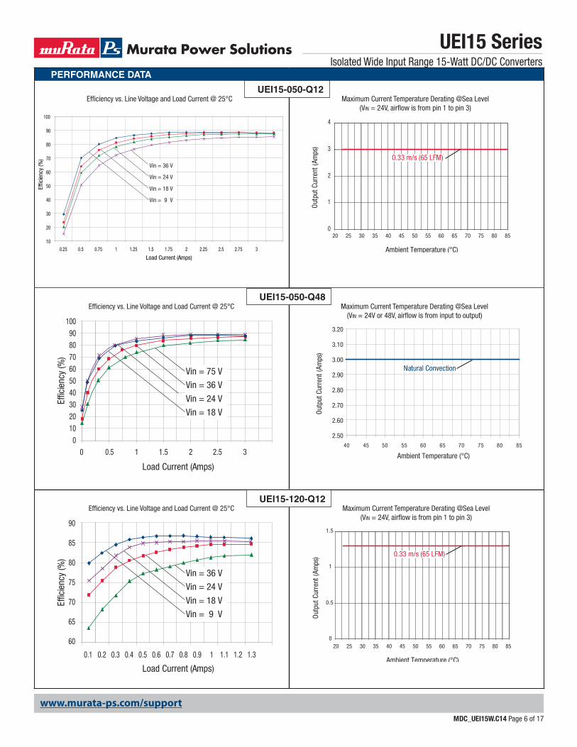
Maximum Current Temperature Derating @Sea Level(VIN = 24V, airfl ow is from pin 1 to pin 3)
0
0.5
1
1.5
0.33 m/s (65 LFM)
Ambient Temperature (°C)
Out
put C
urre
nt (A
mps
)
20 25 35 45 55 65 7530 40 50 60 70 80 85
Maximum Current Temperature Derating @Sea Level(VIN = 24V, airfl ow is from pin 1 to pin 3)
0
1
2
3
4
20 25 35 45 55 65 7530 40 50 60 70 80 85
0.33 m/s (65 LFM)
Ambient Temperature (°C)
Out
put C
urre
nt (A
mps
)
UEI15 SeriesIsolated Wide Input Range 15-Watt DC/DC Converters
MDC_UEI15W.C14 Page 6 of 17
Effi ciency vs. Line Voltage and Load Current @ 25°CUEI15-050-Q48
Load Current (Amps)
Effic
ienc
y (%
)
1009080706050403020100
0 0.5 1 1.5 2 2.5 3
Vin = 36 V
Vin = 75 V
Vin = 18 V
Vin = 24 V
Maximum Current Temperature Derating @Sea Level(VIN = 24V or 48V, airfl ow is from input to output)
40 45 50 55 60 65 70 75 80 85
2.50
2.60
2.70
2.80
2.90
3.00
3.10
3.20
Ambient Temperature (°C)
Out
put C
urre
nt (A
mps
)
Natural Convection
Effi ciency vs. Line Voltage and Load Current @ 25°CUEI15-050-Q12
Load Current (Amps)
Effic
ienc
y (%
)
10
20
30
40
50
60
70
80
90
100
0.25 0.5 0.75 1 1.25 1.5 1.75 2 2.25 2.5 2.75 3
Vin = 24 V
Vin = 36 V
Vin = 9 V
Vin = 18 V
Effi ciency vs. Line Voltage and Load Current @ 25°CUEI15-120-Q12
Load Current (Amps)
Effic
ienc
y (%
)
60
65
70
75
80
85
90
0.1 0.2 0.3 0.4 0.5 0.6 0.7 0.8 0.9 1 1.1 1.2 1.3
Vin = 24 V
Vin = 36 V
Vin = 9 V
Vin = 18 V
www.murata-ps.com/support
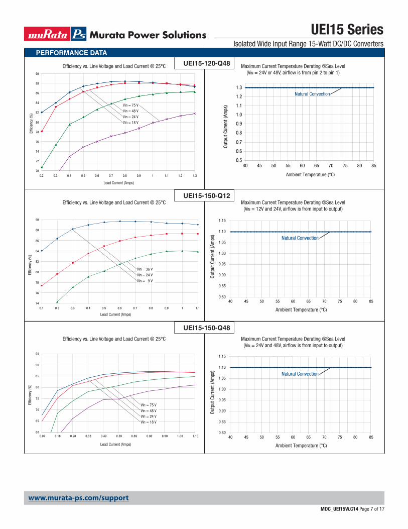
PERFORMANCE DATA
Effi ciency vs. Line Voltage and Load Current @ 25°C UEI15-120-Q48 Maximum Current Temperature Derating @Sea Level(VIN = 24V or 48V, airfl ow is from pin 2 to pin 1)
Load Current (Amps)
Effic
ienc
y (%
)
0.2 0.3 0.4 0.5 0.6 0.7 0.8 0.9 1 1.1 1.2 1.3
70
72
74
76
78
80
82
84
86
88
90
Vin = 48 V
Vin = 75 V
Vin = 18 V
Vin = 24 V
Ambient Temperature (°C)
Out
put C
urre
nt (A
mps
)
0.5
0.6
0.7
0.8
0.9
1.0
1.1
1.2
1.3
40 45 50 55 60 65 70 75 80 85
Natural Convection
Effi ciency vs. Line Voltage and Load Current @ 25°C
Effi ciency vs. Line Voltage and Load Current @ 25°C
UEI15-150-Q12Maximum Current Temperature Derating @Sea Level
(VIN = 12V and 24V, airfl ow is from input to output)
Maximum Current Temperature Derating @Sea Level(VIN = 24V and 48V, airfl ow is from input to output)
Load Current (Amps)
Effic
ienc
y (%
)
74
76
78
80
82
84
86
88
90
0.1 0.2 0.3 0.4 0.5 0.6 0.7 0.8 0.9 1 1.1
Vin = 24 V
Vin = 36 V
Vin = 9 V
Load Current (Amps)
Effic
ienc
y (%
)
60
65
70
75
80
85
90
95
0.07 0.18 0.28 0.38 0.49 0.59 0.69 0.80 0.90 1.00 1.10
Vin = 24 VVin = 48 VVin = 75 V
Vin = 18 V
UEI15-150-Q48
Ambient Temperature (°C)
Out
put C
urre
nt (A
mps
)
0.80
0.85
0.90
0.95
1.00
1.05
1.10
1.15
40 45 50 55 60 65 70 75 80 85
Natural Convection
Ambient Temperature (°C)
Out
put C
urre
nt (A
mps
)
0.80
0.85
0.90
0.95
1.00
1.05
1.10
1.15
40 45 50 55 60 65 70 75 80 85
Natural Convection
UEI15 SeriesIsolated Wide Input Range 15-Watt DC/DC Converters
MDC_UEI15W.C14 Page 7 of 17
www.murata-ps.com/support
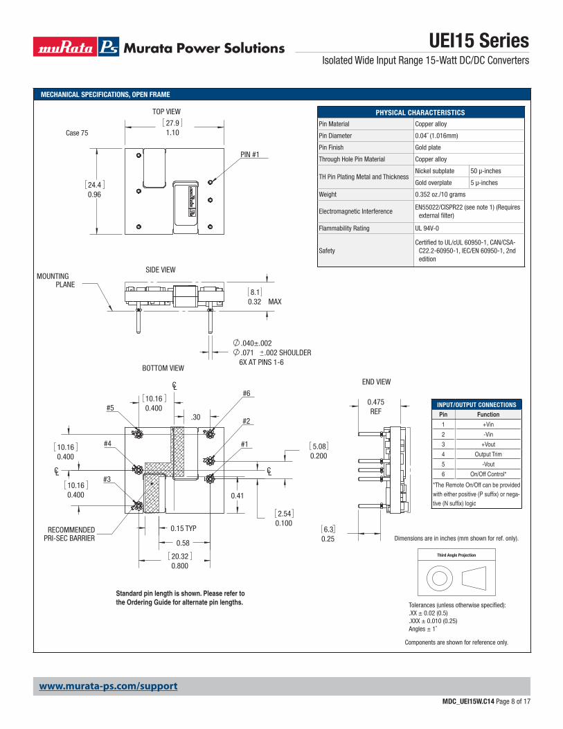
MECHANICAL SPECIFICATIONS, OPEN FRAME
0.32 MAX8.1
0.41
.30
TYP
0.40010.16
0.15
0.58
SIDE VIEWMOUNTING
PLANE
.040±.002
.071 .002 SHOULDER 6X AT PINS 1-6
CL
BOTTOM VIEW
#5
#4
#3
CL
CL
#6
#2
#1
RECOMMENDEDPRI-SEC BARRIER
0.40010.16
0.40010.16
0.1002.54
0.2005.08
0.80020.32
TOP VIEW
PIN #1
1.1027.9
0.9624.4
END VIEW
0.475REF
0.256.3
UEI15 SeriesIsolated Wide Input Range 15-Watt DC/DC Converters
MDC_UEI15W.C14 Page 8 of 17
PHYSICAL CHARACTERISTICS
Pin Material Copper alloy
Pin Diameter 0.04˝ (1.016mm)
Pin Finish Gold plate
Through Hole Pin Material Copper alloy
TH Pin Plating Metal and ThicknessNickel subplate 50 μ-inches
Gold overplate 5 μ-inches
Weight 0.352 oz./10 grams
Electromagnetic InterferenceEN55022/CISPR22 (see note 1) (Requires
external fi lter)
Flammability Rating UL 94V-0
SafetyCertifi ed to UL/cUL 60950-1, CAN/CSA-
C22.2-60950-1, IEC/EN 60950-1, 2nd edition
Case 75
Third Angle Projection
Dimensions are in inches (mm shown for ref. only).
Components are shown for reference only.
Tolerances (unless otherwise specified):.XX ± 0.02 (0.5).XXX ± 0.010 (0.25)Angles ± 1˚
Standard pin length is shown. Please refer to the Ordering Guide for alternate pin lengths.
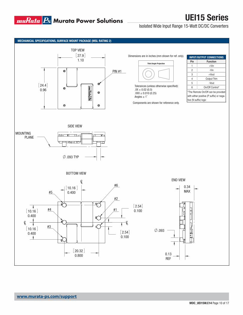
INPUT/OUTPUT CONNECTIONS
Pin Function
1 +Vin
2 -Vin
3 +Vout
4 Output Trim
5 -Vout
6 On/Off Control*
*The Remote On/Off can be provided with either positive (P suffi x) or nega-tive (N suffi x) logic
SECTION A-A
DepthPocket 9.5 [.38 in]
19.1 [.75 in]
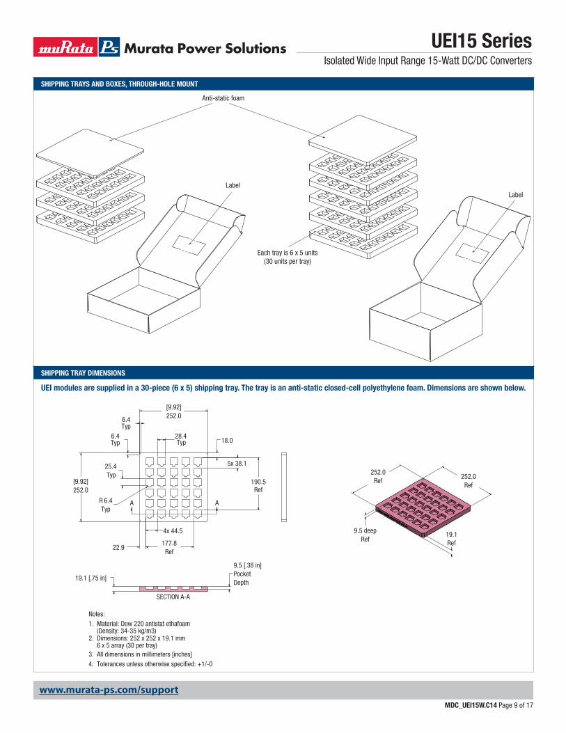
Notes:Material: Dow 220 antistat ethafoam1.(Density: 34-35 kg/m3)Dimensions: 252 x 252 x 19.1 mm2.6 x 5 array (30 per tray)
3. All dimensions in millimeters [inches]4. Tolerances unless otherwise specified: +1/-0
Typ
Typ
R
28.4
177.8
[9.92]252.0
Typ6.4
Typ6.4
6.4Typ 18.0
5x
Ref
38.1
22.9
190.5
Ref
252.0[9.92]
25.4
4x 44.5
AA
19.1Ref
252.0Ref
252.0Ref
9.5 deepRef
www.murata-ps.com/support
SHIPPING TRAYS AND BOXES, THROUGH-HOLE MOUNT
SHIPPING TRAY DIMENSIONS
UEI15 SeriesIsolated Wide Input Range 15-Watt DC/DC Converters
MDC_UEI15W.C14 Page 9 of 17
Anti-static foam
LabelLabel
Each tray is 6 x 5 units(30 units per tray)
UEI modules are supplied in a 30-piece (6 x 5) shipping tray. The tray is an anti-static closed-cell polyethylene foam. Dimensions are shown below.
www.murata-ps.com/support
MECHANICAL SPECIFICATIONS, SURFACE MOUNT PACKAGE (MSL RATING 2)
0.40010.16
0.13REF
0.34MAX
TOP VIEW
PIN #1
1.1027.9
0.9624.4
CL
BOTTOM VIEW
#5
#4
#3
CL
CL
#6
#2
#1
0.40010.16
0.40010.16
0.80020.32
0.1002.54
0.1002.54
END VIEW
.093
SIDE VIEW
MOUNTINGPLANE
.093 TYP
UEI15 SeriesIsolated Wide Input Range 15-Watt DC/DC Converters
MDC_UEI15W.C14 Page 10 of 17
Third Angle Projection
Dimensions are in inches (mm shown for ref. only).
Components are shown for reference only.
Tolerances (unless otherwise specified):.XX ± 0.02 (0.5).XXX ± 0.010 (0.25)Angles ± 1˚
INPUT/OUTPUT CONNECTIONS
Pin Function
1 +Vin
2 -Vin
3 +Vout
4 Output Trim
5 -Vout
6 On/Off Control*
*The Remote On/Off can be provided with either positive (P suffi x) or nega-tive (N suffi x) logic
www.murata-ps.com/support
1.1429.0
±.010.102±0.252.60
10.160.400
0.40010.16
2.540.100
2.54
20.320.800
6X
0.100
1.0025.4 1
2
6
4
5
3
CL
CL
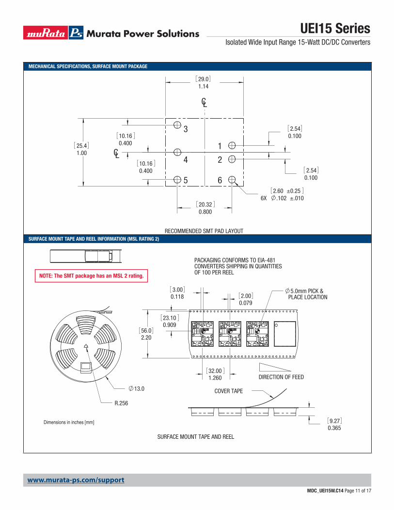
RECOMMENDED SMT PAD LAYOUT
Dimensions in inches [mm]
NOTE: The SMT package has an MSL 2 rating.
MECHANICAL SPECIFICATIONS, SURFACE MOUNT PACKAGE
SURFACE MOUNT TAPE AND REEL INFORMATION (MSL RATING 2)
UEI15 SeriesIsolated Wide Input Range 15-Watt DC/DC Converters
MDC_UEI15W.C14 Page 11 of 17
0.90923.10
32.001.260
2.000.079
0.1183.00
13.0
R.256
DIRECTION OF FEED
5.0mm PICK & PLACE LOCATION
PACKAGING CONFORMS TO EIA-481CONVERTERS SHIPPING IN QUANTITIESOF 100 PER REEL
2.2056.0
COVER TAPE
0.3659.27
SURFACE MOUNT TAPE AND REEL
www.murata-ps.com/support
UEI15 SeriesIsolated Wide Input Range 15-Watt DC/DC Converters
MDC_UEI15W.C14 Page 12 of 17
TECHNICAL NOTES
Input FusingCertain applications and/or safety agencies may require fuses at the inputs of power conversion components. Fuses should also be used when there is the possibility of sustained input voltage reversal which is not current-limited. For greatest safety, we recommend a fast blow fuse installed in the ungrounded input supply line.
The installer must observe all relevant safety standards and regulations. For safety agency approvals, install the converter in compliance with the end-user safety standard, i.e. IEC/EN/UL 60950-1.
Input Reverse-Polarity ProtectionIf the input voltage polarity is reversed, an internal diode will become forward biased and likely draw excessive current from the power source. If this source is not current-limited or the circuit appropriately fused, it could cause perma-nent damage to the converter.
Input Under-Voltage Shutdown and Start-Up ThresholdUnder normal start-up conditions, converters will not begin to regulate properly until the ramping-up input voltage exceeds and remains at the Start-Up Threshold Voltage (see Specifi cations). Once operating, converters will not turn off until the input voltage drops below the Under-Voltage Shutdown Limit. Subsequent restart will not occur until the input voltage rises again above the Start-Up Threshold. This built-in hysteresis prevents any unstable on/off opera-tion at a single input voltage.
Users should be aware however of input sources near the Under-Voltage Shutdown whose voltage decays as input current is consumed (such as capaci-tor inputs), the converter shuts off and then restarts as the external capacitor recharges. Such situations could oscillate. To prevent this, make sure the oper-ating input voltage is well above the UV Shutdown voltage AT ALL TIMES.
Start-Up TimeAssuming that the output current is set at the rated maximum, the VIN to VOUT Start-Up Time (see Specifi cations) is the time interval between the point when the ramping input voltage crosses the Start-Up Threshold and the fully loaded regulated output voltage enters and remains within its specifi ed accuracy band. Actual measured times will vary with input source impedance, external input capacitance, input voltage slew rate and fi nal value of the input voltage as it appears at the converter.
These converters include a soft start circuit to moderate the duty cycle of its PWM controller at power up, thereby limiting the input inrush current.
The On/Off Remote Control interval from On command to VOUT regulated assumes that the converter already has its input voltage stabilized above the Start-Up Threshold before the On command. The interval is measured from the On command until the output enters and remains within its specifi ed accuracy band. The specifi cation assumes that the output is fully loaded at maximum rated current. Similar conditions apply to the On to VOUT regulated specifi cation such as external load capacitance and soft start circuitry.
Input Source ImpedanceThese converters will operate to specifi cations without external components, assuming that the source voltage has very low impedance and reasonable in-
put voltage regulation. Since real-world voltage sources have fi nite impedance, performance is improved by adding external fi lter components. Sometimes only a small ceramic capacitor is suffi cient. Since it is diffi cult to totally characterize all applications, some experimentation may be needed. Note that external input capacitors must accept high speed switching currents.
Because of the switching nature of DC/DC converters, the input of these converters must be driven from a source with both low AC impedance and adequate DC input regulation. Performance will degrade with increasing input inductance. Excessive input inductance may inhibit operation. The DC input regulation specifi es that the input voltage, once operating, must never degrade below the Shut-Down Threshold under all load conditions. Be sure to use adequate trace sizes and mount components close to the converter.
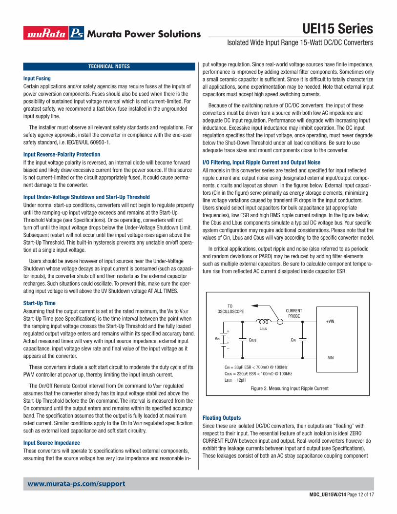
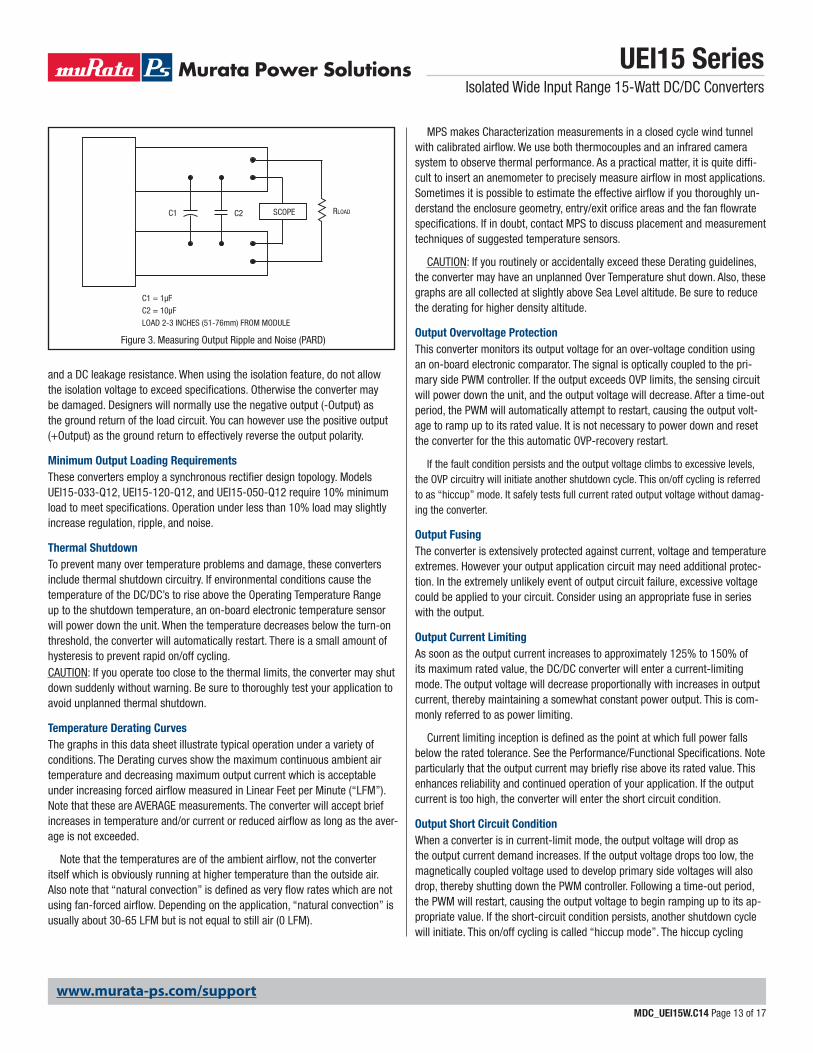
I/O Filtering, Input Ripple Current and Output NoiseAll models in this converter series are tested and specifi ed for input refl ected ripple current and output noise using designated external input/output compo-nents, circuits and layout as shown in the fi gures below. External input capaci-tors (Cin in the fi gure) serve primarily as energy storage elements, minimizing line voltage variations caused by transient IR drops in the input conductors. Users should select input capacitors for bulk capacitance (at appropriate frequencies), low ESR and high RMS ripple current ratings. In the fi gure below, the Cbus and Lbus components simulate a typical DC voltage bus. Your specifi c system confi guration may require additional considerations. Please note that the values of Cin, Lbus and Cbus will vary according to the specifi c converter model.
In critical applications, output ripple and noise (also referred to as periodic and random deviations or PARD) may be reduced by adding fi lter elements such as multiple external capacitors. Be sure to calculate component tempera-ture rise from refl ected AC current dissipated inside capacitor ESR.
CINVIN CBUS
LBUS
CIN = 33μF, ESR < 700mΩ @ 100kHz
CBUS = 220μF, ESR < 100mΩ @ 100kHz
LBUS = 12μH
+VIN
-VIN
CURRENTPROBE
TO OSCILLOSCOPE
+–+–
Figure 2. Measuring Input Ripple Current
Floating OutputsSince these are isolated DC/DC converters, their outputs are “fl oating” with respect to their input. The essential feature of such isolation is ideal ZERO CURRENT FLOW between input and output. Real-world converters however do exhibit tiny leakage currents between input and output (see Specifi cations). These leakages consist of both an AC stray capacitance coupling component
www.murata-ps.com/support
UEI15 SeriesIsolated Wide Input Range 15-Watt DC/DC Converters
MDC_UEI15W.C14 Page 13 of 17
and a DC leakage resistance. When using the isolation feature, do not allow the isolation voltage to exceed specifi cations. Otherwise the converter may be damaged. Designers will normally use the negative output (-Output) as the ground return of the load circuit. You can however use the positive output (+Output) as the ground return to effectively reverse the output polarity.
Minimum Output Loading RequirementsThese converters employ a synchronous rectifi er design topology. Models UEI15-033-Q12, UEI15-120-Q12, and UEI15-050-Q12 require 10% minimum load to meet specifi cations. Operation under less than 10% load may slightly increase regulation, ripple, and noise.
Thermal ShutdownTo prevent many over temperature problems and damage, these converters include thermal shutdown circuitry. If environmental conditions cause the temperature of the DC/DC’s to rise above the Operating Temperature Range up to the shutdown temperature, an on-board electronic temperature sensor will power down the unit. When the temperature decreases below the turn-on threshold, the converter will automatically restart. There is a small amount of hysteresis to prevent rapid on/off cycling. CAUTION: If you operate too close to the thermal limits, the converter may shut down suddenly without warning. Be sure to thoroughly test your application to avoid unplanned thermal shutdown.
Temperature Derating CurvesThe graphs in this data sheet illustrate typical operation under a variety of conditions. The Derating curves show the maximum continuous ambient air temperature and decreasing maximum output current which is acceptable under increasing forced airfl ow measured in Linear Feet per Minute (“LFM”). Note that these are AVERAGE measurements. The converter will accept brief increases in temperature and/or current or reduced airfl ow as long as the aver-age is not exceeded.
Note that the temperatures are of the ambient airfl ow, not the converter itself which is obviously running at higher temperature than the outside air. Also note that “natural convection” is defi ned as very fl ow rates which are not using fan-forced airfl ow. Depending on the application, “natural convection” is usually about 30-65 LFM but is not equal to still air (0 LFM).
MPS makes Characterization measurements in a closed cycle wind tunnel with calibrated airfl ow. We use both thermocouples and an infrared camera system to observe thermal performance. As a practical matter, it is quite diffi -cult to insert an anemometer to precisely measure airfl ow in most applications. Sometimes it is possible to estimate the effective airfl ow if you thoroughly un-derstand the enclosure geometry, entry/exit orifi ce areas and the fan fl owrate specifi cations. If in doubt, contact MPS to discuss placement and measurement techniques of suggested temperature sensors.
CAUTION: If you routinely or accidentally exceed these Derating guidelines, the converter may have an unplanned Over Temperature shut down. Also, these graphs are all collected at slightly above Sea Level altitude. Be sure to reduce the derating for higher density altitude.
Output Overvoltage ProtectionThis converter monitors its output voltage for an over-voltage condition using an on-board electronic comparator. The signal is optically coupled to the pri-mary side PWM controller. If the output exceeds OVP limits, the sensing circuit will power down the unit, and the output voltage will decrease. After a time-out period, the PWM will automatically attempt to restart, causing the output volt-age to ramp up to its rated value. It is not necessary to power down and reset the converter for the this automatic OVP-recovery restart.
If the fault condition persists and the output voltage climbs to excessive levels, the OVP circuitry will initiate another shutdown cycle. This on/off cycling is referred to as “hiccup” mode. It safely tests full current rated output voltage without damag-ing the converter.
Output FusingThe converter is extensively protected against current, voltage and temperature extremes. However your output application circuit may need additional protec-tion. In the extremely unlikely event of output circuit failure, excessive voltage could be applied to your circuit. Consider using an appropriate fuse in series with the output.
Output Current LimitingAs soon as the output current increases to approximately 125% to 150% of its maximum rated value, the DC/DC converter will enter a current-limiting mode. The output voltage will decrease proportionally with increases in output current, thereby maintaining a somewhat constant power output. This is com-monly referred to as power limiting.
Current limiting inception is defi ned as the point at which full power falls below the rated tolerance. See the Performance/Functional Specifi cations. Note particularly that the output current may briefl y rise above its rated value. This enhances reliability and continued operation of your application. If the output current is too high, the converter will enter the short circuit condition.
Output Short Circuit ConditionWhen a converter is in current-limit mode, the output voltage will drop as the output current demand increases. If the output voltage drops too low, the magnetically coupled voltage used to develop primary side voltages will also drop, thereby shutting down the PWM controller. Following a time-out period, the PWM will restart, causing the output voltage to begin ramping up to its ap-propriate value. If the short-circuit condition persists, another shutdown cycle will initiate. This on/off cycling is called “hiccup mode”. The hiccup cycling
Figure 3. Measuring Output Ripple and Noise (PARD)
C1
C1 = 1μF
C2 = 10μF
LOAD 2-3 INCHES (51-76mm) FROM MODULE
C2 RLOADSCOPE
www.murata-ps.com/support
UEI15 SeriesIsolated Wide Input Range 15-Watt DC/DC Converters
MDC_UEI15W.C14 Page 14 of 17
reduces the average output current, thereby preventing excessive internal temperatures. A short circuit can be tolerated indefi nitely.
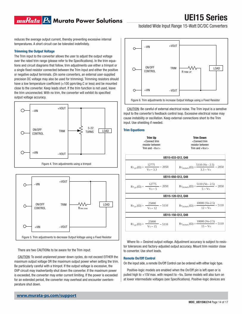
Trimming the Output VoltageThe Trim input to the converter allows the user to adjust the output voltage over the rated trim range (please refer to the Specifi cations). In the trim equa-tions and circuit diagrams that follow, trim adjustments use either a trimpot or a single fi xed resistor connected between the Trim input and either the positive or negative output terminals. (On some converters, an external user-supplied precision DC voltage may also be used for trimming). Trimming resistors should have a low temperature coeffi cient (±100 ppm/deg.C or less) and be mounted close to the converter. Keep leads short. If the trim function is not used, leave the trim unconnected. With no trim, the converter will exhibit its specifi ed output voltage accuracy.
There are two CAUTIONs to be aware for the Trim input:
CAUTION: To avoid unplanned power down cycles, do not exceed EITHER the maximum output voltage OR the maximum output power when setting the trim. Be particularly careful with a trimpot. If the output voltage is excessive, the OVP circuit may inadvertantly shut down the converter. If the maximum power is exceeded, the converter may enter current limiting. If the power is exceeded for an extended period, the converter may overheat and encounter overtem-perature shut down.
Figure 4. Trim adjustments using a trimpot
LOAD75-22TURNS
+VOUT
TRIM
−VOUT
−VIN
ON/OFFCONTROL
+VIN
Figure 6. Trim adjustments to increase Output Voltage using a Fixed Resistor
+VOUT
TRIM ON/OFFCONTROL
+VIN
LOADR TRIM UP
−VOUT
−VIN
Figure 5. Trim adjustments to decrease Output Voltage using a Fixed Resistor
LOADRTRIM DOWN
+VOUT
TRIM ON/OFFCONTROL
+VIN −VOUT
−VINVO – 5
– 205012775
– 20505 – VO
5110 (Vo - 2.5)
VO – 12– 5110
25000– 5110
12 – VO
10000 (Vo-2.5)
UEI15-050-Q12, Q48
UEI15-120-Q12, Q48
VO – 3.3– 2050
12775RTDOWN () =RTUP () =
RTUP () =
RTUP () =
RTUP () =
RTDOWN () =
RTDOWN () =
RTDOWN () =
– 20503.3 – VO
5110 (Vo - 2.5)
UEI15-033-Q12, Q48
VO – 15– 5110
25000– 5110
15 – VO
10000 (Vo-2.5)
UEI15-150-Q12, Q48
Trim Up<Connect trim
resistor betweenTrim and −VOUT>
Trim Down<Connect trim
resistor betweenTrim and +VOUT>
CAUTION: Be careful of external electrical noise. The Trim input is a senstive input to the converter’s feedback control loop. Excessive electrical noise may cause instability or oscillation. Keep external connections short to the Trim input. Use shielding if needed.
Trim Equations
Where Vo = Desired output voltage. Adjustment accuracy is subject to resis-tor tolerances and factory-adjusted output accuracy. Mount trim resistor close to converter. Use short leads.
Remote On/Off ControlOn the input side, a remote On/Off Control can be ordered with either logic type.
Positive-logic models are enabled when the On/Off pin is left open or is pulled high to +15V max. with respect to –VIN. Some models will also turn on at lower intermediate voltages (see Specifi cations). Positive-logic devices are
www.murata-ps.com/support
UEI15 SeriesIsolated Wide Input Range 15-Watt DC/DC Converters
MDC_UEI15W.C14 Page 15 of 17
disabled when the On/Off is grounded or brought to within a low voltage (see Specifi cations) with respect to –VIN.
Negative-logic devices are on (enabled) when the On/Off is grounded or brought to within a low voltage (see Specifi cations) with respect to –VIN. The device is off (disabled) when the On/Off is left open or is pulled high to +15VDC max. with respect to –VIN.
Dynamic control of the On/Off function should be able to sink appropriate signal current when brought low and withstand appropriate voltage when brought high. Be aware too that there is a fi nite time in milliseconds (see Specifi cations) between the time of On/Off Control activation and stable, regulated output. This time will vary slightly with output load type and current and input conditions.
There are three CAUTIONs for the On/Off Control:
CAUTION: To retain full output circuit isolation, control the On/Off from the in-put side ONLY. If you must control it from circuits in the output, use some form of optoisolation to the On/Off Control. This latter condition is unlikely because the device controlling the On/Off would have to remain powered on and not be powered from the converter.
CAUTION: While it is possible to control the On/Off with external logic if you carefully observe the voltage levels, the preferred circuit is either an open drain/open collector transistor, a switch or a relay (which can thereupon be controlled by logic).
CAUTION: Do not apply voltages to the On/Off pin when there is no input power voltage. Otherwise the converter may be permanently damaged.
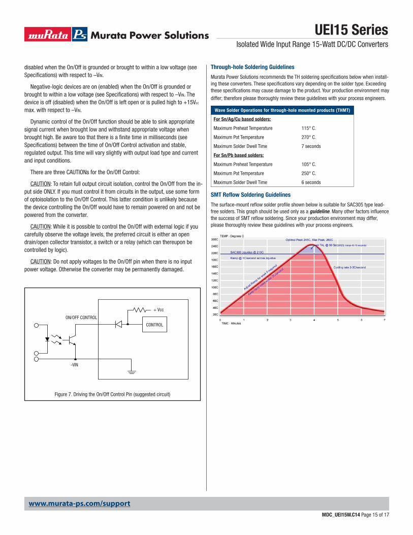
Figure 7. Driving the On/Off Control Pin (suggested circuit)
ON/OFF CONTROL
CONTROL
+ Vcc
-VIN
Through-hole Soldering Guidelines
Murata Power Solutions recommends the TH soldering specifi cations below when install-ing these converters. These specifi cations vary depending on the solder type. Exceeding these specifi cations may cause damage to the product. Your production environment may
differ; therefore please thoroughly review these guidelines with your process engineers.
Wave Solder Operations for through-hole mounted products (THMT)
For Sn/Ag/Cu based solders:
Maximum Preheat Temperature 115° C.
Maximum Pot Temperature 270° C.
Maximum Solder Dwell Time 7 seconds
For Sn/Pb based solders:
Maximum Preheat Temperature 105° C.
Maximum Pot Temperature 250° C.
Maximum Solder Dwell Time 6 seconds
SMT Refl ow Soldering Guidelines
The surface-mount refl ow solder profi le shown below is suitable for SAC305 type lead-free solders. This graph should be used only as a guideline. Many other factors infl uence the success of SMT refl ow soldering. Since your production environment may differ, please thoroughly review these guidelines with your process engineers.
www.murata-ps.com/support
UEI15 SeriesIsolated Wide Input Range 15-Watt DC/DC Converters
MDC_UEI15W.C14 Page 16 of 17
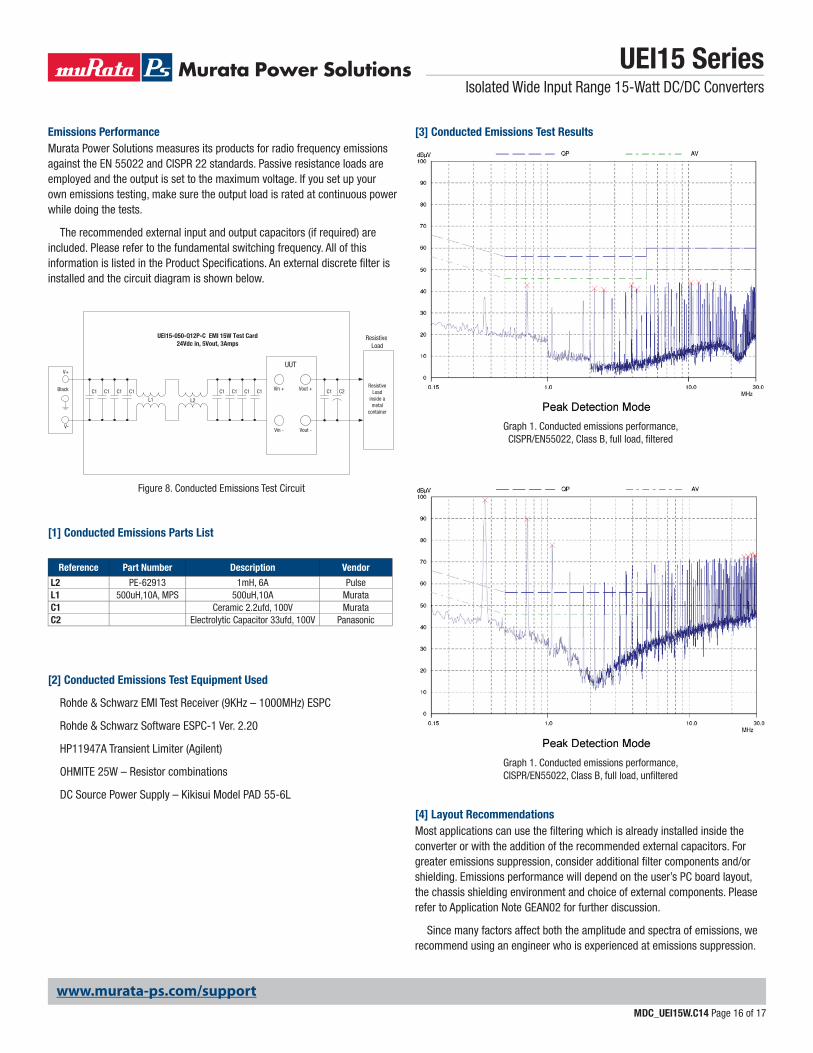
Emissions PerformanceMurata Power Solutions measures its products for radio frequency emissions against the EN 55022 and CISPR 22 standards. Passive resistance loads are employed and the output is set to the maximum voltage. If you set up your own emissions testing, make sure the output load is rated at continuous power while doing the tests.
The recommended external input and output capacitors (if required) are included. Please refer to the fundamental switching frequency. All of this information is listed in the Product Specifi cations. An external discrete fi lter is installed and the circuit diagram is shown below.
[1] Conducted Emissions Parts List
[2] Conducted Emissions Test Equipment Used
Rohde & Schwarz EMI Test Receiver (9KHz – 1000MHz) ESPC
Rohde & Schwarz Software ESPC-1 Ver. 2.20
HP11947A Transient Limiter (Agilent)
OHMITE 25W – Resistor combinations
DC Source Power Supply – Kikisui Model PAD 55-6L
[3] Conducted Emissions Test Results
[4] Layout RecommendationsMost applications can use the fi ltering which is already installed inside the converter or with the addition of the recommended external capacitors. For greater emissions suppression, consider additional fi lter components and/or shielding. Emissions performance will depend on the user’s PC board layout, the chassis shielding environment and choice of external components. Please refer to Application Note GEAN02 for further discussion.
Since many factors affect both the amplitude and spectra of emissions, we recommend using an engineer who is experienced at emissions suppression.
Reference Part Number Description Vendor
L2 PE-62913 1mH, 6A PulseL1 500uH,10A, MPS 500uH,10A MurataC1 Ceramic 2.2ufd, 100V MurataC2 Electrolytic Capacitor 33ufd, 100V Panasonic
Graph 1. Conducted emissions performance, CISPR/EN55022, Class B, full load, fi ltered
Graph 1. Conducted emissions performance, CISPR/EN55022, Class B, full load, unfi ltered
Figure 8. Conducted Emissions Test Circuit
UEI15-050-Q12P-C EMI 15W Test Card24Vdc in, 5Vout, 3Amps
V+
V-
Black
Vin - Vout -
Vout +Vin +
Resistive Load
UUT
L2L1
C1C1C1C1 C1C1 C2C1C1C1Resistive
Loadinside ametal
container
www.murata-ps.com/support
Murata Power Solutions, Inc. makes no representation that the use of its products in the circuits described herein, or the use of other technical information contained herein, will not infringe upon existing or future patent rights. The descriptions contained herein do not imply the granting of licenses to make, use, or sell equipment constructed in accordance therewith. Specifi cations are subject to change without notice. © 2013 Murata Power Solutions, Inc.
Murata Power Solutions, Inc. 11 Cabot Boulevard, Mansfi eld, MA 02048-1151 U.S.A.ISO 9001 and 14001 REGISTERED
This product is subject to the following operating requirements and the Life and Safety Critical Application Sales Policy: Refer to: http://www.murata-ps.com/requirements/
UEI15 SeriesIsolated Wide Input Range 15-Watt DC/DC Converters
MDC_UEI15W.C14 Page 17 of 17
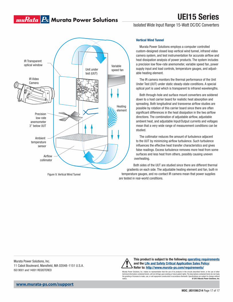
Figure 9. Vertical Wind Tunnel
IR Video Camera
IR Transparentoptical window Variable
speed fan
Heating element
Ambient temperature
sensor
Airflowcollimator
Precisionlow-rate
anemometer3” below UUT
Unit undertest (UUT)
Vertical Wind Tunnel
Murata Power Solutions employs a computer controlled custom-designed closed loop vertical wind tunnel, infrared video camera system, and test instrumentation for accurate airfl ow and heat dissipation analysis of power products. The system includes a precision low fl ow-rate anemometer, variable speed fan, power supply input and load controls, temperature gauges, and adjust-able heating element.
The IR camera monitors the thermal performance of the Unit Under Test (UUT) under static steady-state conditions. A special optical port is used which is transparent to infrared wavelengths.
Both through-hole and surface mount converters are soldered down to a host carrier board for realistic heat absorption and spreading. Both longitudinal and transverse airfl ow studies are possible by rotation of this carrier board since there are often signifi cant differences in the heat dissipation in the two airfl ow directions. The combination of adjustable airfl ow, adjustable ambient heat, and adjustable Input/Output currents and voltages mean that a very wide range of measurement conditions can be studied.
The collimator reduces the amount of turbulence adjacent to the UUT by minimizing airfl ow turbulence. Such turbulence infl uences the effective heat transfer characteristics and gives false readings. Excess turbulence removes more heat from some surfaces and less heat from others, possibly causing uneven
overheating.
Both sides of the UUT are studied since there are different thermal gradients on each side. The adjustable heating element and fan, built-in
temperature gauges, and no-contact IR camera mean that power supplies are tested in real-world conditions.


