
TTA-Based Co-design Environment (TCE)Tutorial
v.1.1authors: Otto EskoPekka Jääskeläinen
This work is licensed under the Creative Commons Attribution 3.0 Unported License: http://creativecommons.org/licenses/by/3.0/

Outline
• TCE design flow overview• TCE design flow tutorial
• TCE Tour: From C code to an Application Specific Processor RTL
• Summary

TCE ASIP Design Flow

TCE Custom Operation Flow

Application
• Tutorial application is CRC-32• Cyclic Redundancy Check
• Application will be analyzed and accelerated• We will create ASIP RTL from the application
• C to VHDL
• Download tutorial files from http://tce.cs.tut.fi/tutorial_files/tce_tutorials.tar.gz
• Unpack with: tar -xzf tce_tutorials.tar.gz

TCE ASIP Design Flow

Compile the application
• Copy the starting point architecture to tutorial folder: cp /usr/local/share/tce/data/mach/minimal.adf start.adf
• Open the architecture in Processor Designer tool:
• prode start.adf• Adjust address spaces
• Compile the source code for starting point architecture• tcecc -O3 -a start.adf -o crc.tpef -k result main.c crc.c

TCE ASIP Design Flow

Simulate using Proxim GUI
• Start proxim:• proxim start.adf crc.tpef &
• Execution can be followed from machine window:
• Select View -> Machine Window• Try stepping the execution
• Click Run or Resume to finish execution

Proxim cont.
• Result can be checked from the result variable• x /u w _result
• Correct result is 0x62488e82
• Cycle count is at bottom right• Command “info proc cycles” also shows them
• Write down the cycle count for comparison
• Resource usage statistics can be seen• info proc stats

TCE Custom Operation Flow

Analyze the application
• Open file crc.c in a text editor• crcFast function calls reflect function using
REFLECT_DATA macro• Then performs bitwise xor-operation• Reflect is also called at the end of the function
with REFLECT_REMAINDER macro
• Reflect function reflects the input bit pattern• Iterative on software• Can be done concurrently on hardware
• Good custom operation candidate

Reflect operation: SW vs. HW
On software: On hardware:
for (bit = 0; bit < nBits; bit++) {
if (data & 0x01) {
reflection I=
(1 << ((nBits-1) – bit));
}
data = (data >> 1);
}
7 6 5 4 3 2 1 0
0 1 2 3 4 5 6 7
INPUT DATA
OUTPUT DATA
Registers

Further analyzation
• Reflect is performed for 8-bit and 32-bit data• Can be done on same hardware
• 32-bit crosswiring• Need to add multiplexers before registers for 8-bit
reflections
• Not much logic needed• Can be done in one clock cycle• -> operation latency is 1 cycle
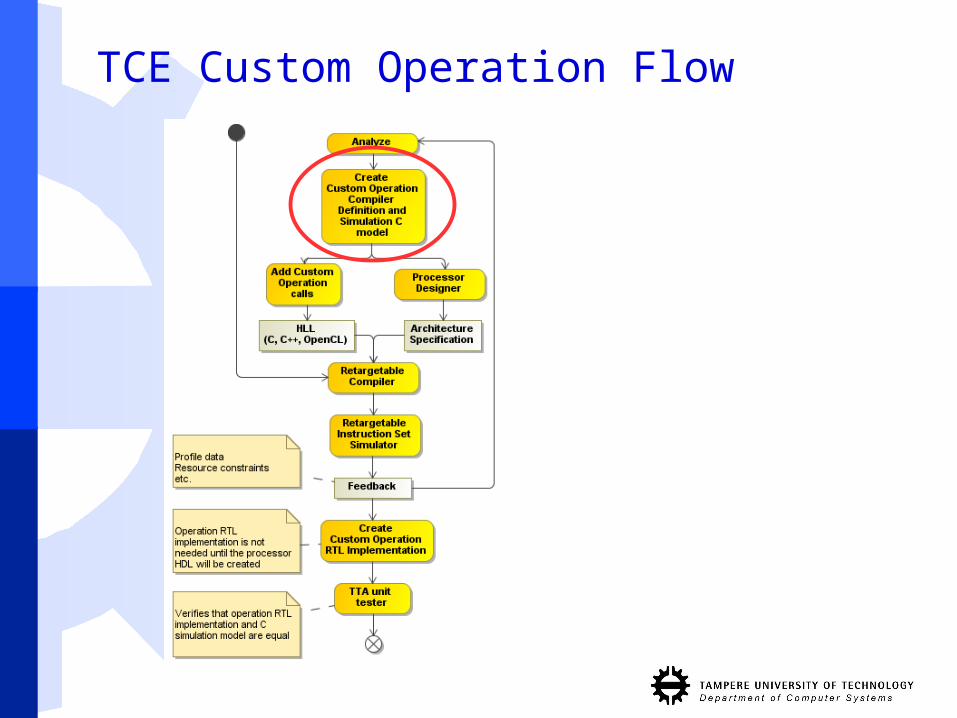
TCE Custom Operation Flow

Add custom operation definitions
• Operation definition tells the semantics of the operation to compiler
• Open operation set editor
• osed &
• Add new module
• Right click /home/tce/.tce/opset -> Add module
• Name it as “tutorial”
• Add operation
• Name the operation REFLECT8
• Add 1 UIntWord input port
• Add 1 UIntWord output port
• Click OK
• Repeat for operation REFLECT32

Add custom operation simulation model• C++ simulation model is needed to simulate the
operation
• We can use the original reflect function as the simulation model.
• It needs some small changes
• Right click REFLECT8 and select Modify Behavior
• Copy-paste the operation behavior from the user manual or from file custom_operation_behavior.cc
• Save the file
• Compile the behavior by right clicking “tutorial” and select build
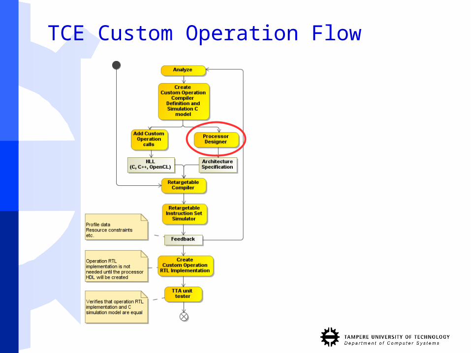
TCE Custom Operation Flow

Add SFU to architecture• We need to add a Function Unit that supports the custom
operations into our architecture
• First copy the current architecture
• cp start.adf custom.adf
• Open the copy in ProDe
• prode custom.adf &
• Select Edit -> Add -> Function Unit...
• Name the function unit as REFLECTER (capital letters!)
• Add port:• name it input1• check the “Triggers” box
• Add another port• name it output1

Add SFU cont.
• Add operations by clicking Add from opset...
• Select REFLECT8
• Check that latency is 1
• Repeat for operation REFLECT32
• Close the dialog with OK
• Connect the function unit
• Select Tools -> Fully Connect IC
• Save the architecture
• Now the processor architecture supports REFLECT8 and REFLECT32 operations

TCE Custom Operation Flow

Add custom operation calls
• Copy crc.c• cp crc.c crc_with_custom_op.c
• Open crc_with_custom_op.c in text editor
• Add #include “tceops.h” to the top
• Locate crcFast function
• Add 2 new variables to the beginning of crcFast function crc input = 0;
crc output = 0;
• Modify the for-loop: input = message[byte];
_TCE_REFLECT8(input, output);
data = output ^ (remainder >> (WIDTH - 8));
remainder = crcTable[data] ^ (remainder << 8);
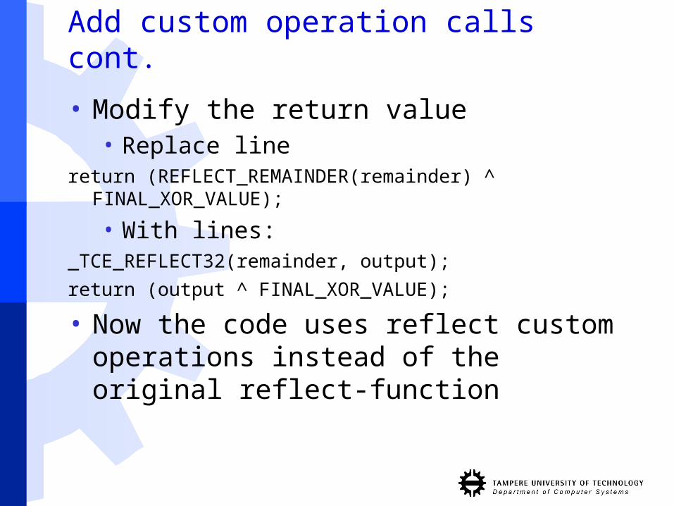
Add custom operation calls cont.
• Modify the return value• Replace line
return (REFLECT_REMAINDER(remainder) ^ FINAL_XOR_VALUE);
• With lines:_TCE_REFLECT32(remainder, output);
return (output ^ FINAL_XOR_VALUE);
• Now the code uses reflect custom operations instead of the original reflect-function
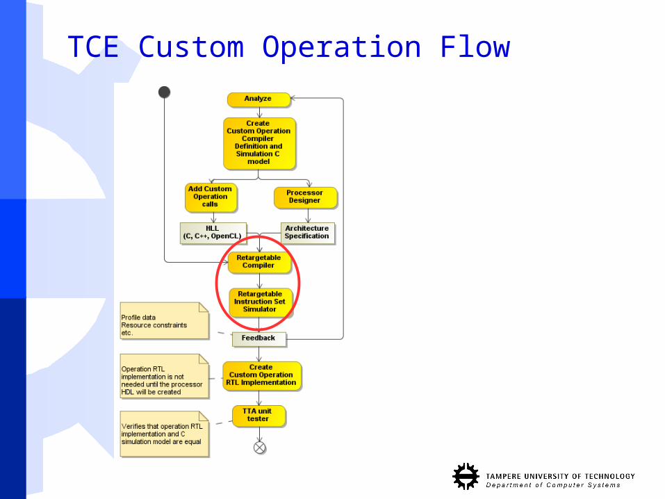
TCE Custom Operation Flow

Compile and simulate with custom operation
• Compile the new codetcecc -O3 -a custom.adf -o crc_with_custom_op.tpef -k
result main.c crc_with_custom_op.c
• This time we will use the command line simulator ttasim and produce bus trace for RTL verification
• Launch ttasim:
• ttasim
• Enable bus trace setting:
• setting bus_trace 1

Simulate cont.
• Load architecture and program and execute program
• mach custom.adf
• prog crc_with_custom_op.tpef
• run
• Verify result (should be 0x62488e82)
• x /u w _result
• Check cycle count
• info proc cycles
• WOW!
• Simulator produced the bus trace in file crc_with_custom_op.tpef.bustrace
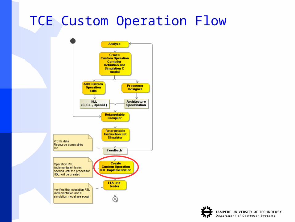
TCE Custom Operation Flow
Add SFU implementation to HDB
• In order to create processor VHDL we need to add HW implementation for the new Special Function Unit
• Implementation is in file tour_vhdl/reflect.vhdl• Open it in text editor
• Next step is add the implementation to Hardware Database (HDB)• Map HW ports to architecture ports in HDB• Add generic values to HDB• Add HW implementation files to HDB

Add SFU cont.
• To speed up things we’ll use the given tour_example.hdb
• Open hardware database editor to take a look at the hdb:• hdbeditor tour_example.hdb &

TCE ASIP Design Flow

Generate processor RTL implementation
• Open the architecture in ProDe
• prode custom.adf &
• select Tools -> Processor Implementation
• Next step is to select implementations for the function units
• But we will skip this and use the given implementation description file
• Click Load IDF... and select file custom_operations.idf

Generate processor cont
• In Binary Encoding Map dialog
• Select Generate new
• Target directory dialog
• Click Browse...
• Create new folder: proge-output
• Select it
• Click OK to generate processor
• Processor RTL implementation is now in folder proge-output

TCE ASIP Design Flow

Generate program binary images
• Now we need the program images for the processor• generatebits -d -w 4 -p crc_with_custom_op.tpef
-x proge-output custom.adf
• Command creates• Instruction memory image crc_with_custom_op.img
• Data memory image crc_with_custom_op_data.img

VHDL simulation
• Go to proge-output folder• cp proge-output
• Copy images for the testbench• cp ../crc_with_custom_op.img tb/imem_init.img
• cp ../crc_with_custom_op_data.img tb/dmem_init.img
• Compile testbench• ./ghdl_compile.sh
• Simulate testbench• ./ghdl_simulate.sh
• This will take some time

Verification
• We can compare the bus traces to verify RTL simulation
• Cut RTL simulation bus trace to match the ttasim bus trace• head -n (cycle count) bus.dump > sim.dump
• Compare bus traces• diff -u sim.dump ../crc_with_custom_op.tpef.bustrace
• If there is no output traces were equal

Summary
• TTA is a customizable processor architecture template
• We have covered the basics of the TCE design flow • You now know how to
• Modify a processor architecture
• Create and add custom operations
• Create RTL implementation of the processor and binary images of the program
• Verify the implementation
• Simple custom operation increased the performance significantly
• Performance can be also increased by adding more resources to the processor• You can try it on your own


