
TrueSite™ Workstation
1
TrueSite™
Workstation
Version 2.01 Enhancements

TrueSite™ Workstation
2
Target Sales Opportunities
• GCC/IMS Upgrades: allows existing GCC/IMS Customers to upgrade to
the latest technology at a reduced cost
• Medium-to-Large Network Systems: integrate competitor and legacy
systems into a centralized, agency listed, annunciation and information
management network workstation
Customer’s For Life!

TrueSite™ Workstation
3
Mid-Rise
High-Rise
Typical TSW Markets
• Single Buildings: 500,000 Square Feet or Greater
Large Single Story
• Campus: Any Multi-Building Campus Facility
• Users: Building Fire & Security, Facilities & Engineering
Management
Multi-Building

TrueSite™ Workstation
4
Target Vertical Markets
College & University
Hospitals
Industrial
GovernmentCommercialHospitality
Criminal Justice
Mass Notification

TrueSite™ Workstation
5
A State-of-the-Art Platform for Managing Multiple
Fire Alarm Panels and Networks
Multiple Remote Client Ethernet Connectivity to
Leverage Customer’s Existing LAN/WAN for Remote
Graphics Annunciation
Centralized Total System Monitoring of ANY Panel
from ANY Manufacturer
Centralized Point Status and Control
Intuitive Operator Graphics to Facilitate Rapid
Response to Emergencies and Reduced Operator
Training
System Diagnostic Tools to Simplify the Identification
and Correction of Fault Conditions
Extensive Service and Status Reporting for
Verification of System Status and Performance
Extensive Event/Alarm Historical Data Logging for
Verification of System Activity and Operation
What is a TrueSite™ Workstation?

TrueSite™ Workstation
6
• A PC-based, Life Safety Information Management System
• An Intuitive Graphical User Interface for High-End Primary Fire Alarm
Workstation and Remote Workstation Applications
• Supports Multiple Remote Clients via TCP/IP Ethernet Connectivity
Customer
LAN / WAN
TSW Client Manager’s Office
(unsupervised / view only)
TSW Client Manager’s Home
(unsupervised / view only)
TSW Server
Fire Alarm Command Center
TSW Client at Guard’s Shack
(supervised / full control)
FA Ethernet Switch
Agency Listed
FA Ethernet LAN
TrueSite™ Workstation Product Overview

TrueSite™ Workstation
7
Key TSW Features Summary
• Centralized Safety and Information Management
• Superior Technology:
– Multiple Remote Client Connectivity via Ethernet
– AutoCAD Compatible Graphics Import and Export
– Dynamic Pan-and-Zoom Graphics
– Dockable and Floating Windows for Multiple Monitor Applications; e.g.
• 1 Graphics Monitor / 1 Reports Monitor
• Agency Listed, Seamless Integration of Any Panel from Any Manufacturer
– Optional DACR Interface bridges Competitive and Legacy Control Panels into a Central
Annunciator Workstation
• Intuitive Operation for Maximum Operator Efficiency and Minimum Training
Requirements
– Accelerated Accurate Response Reduces Customer’s Liability and Risks
• Forward/Backward Compatibility with Existing Simplex Fire Network Systems
– Protects Customer’s Investment & Reduces Life-Cycle Cost
– Reduced Priced Upgrades are Available for Existing GCC/IMS Customer Systems
Customer Focus, Customer Value

TrueSite™ Workstation
8
TrueSite™
Workstation
Ver 2.01 Enhancements Review

TrueSite™ Workstation
9
TrueSite™ Workstation 2.01 Enhancements
• TSW Client / Server Ethernet Connectivity
• 7 Network Loops
• Graphics Key Plan
• Non-Zoomable Screen Area
• Enhanced Coverage Zone Operation
• GIF and JPG File Import (supports animated GIF files)
• USB Event Printer and Network Graphics/Report/Screen Printing
• Updated Localization Kit for Language Translations
• Verified Compatible with Symantec AV Corporate Edition 10.2 and McAfee Enterprise
8.5.0i Anti Virus Software

TrueSite™ Workstation
10
TrueSite™ Workstation 2.01
Competitive Comparison
Feature
Simplex Notifier EST Siemens
TSW NCS FireWorks NCCXP
Multiple loops Yes (7) No Yes (not a node) No
Non-fire apps Yes No Yes No
Dual monitors Yes No No No
Dockable windows Yes No No No
DACR Application Yes No (UniNet only) Yes No
Integrated graphics Yes ? Yes n/a
IP DACT support Yes Yes Yes n/a
Choice of DACRs Yes (3) Yes (4) Yes (3) n/a
Monitor
LCD Yes (17”, 19”) Yes (19”) Yes (18”) Yes (19”)
Touch screen Yes No Yes Yes
Client Server
Remote Clients 10 Clients No 5 No
5 supervised
5 unsupervised

TrueSite™ Workstation
11
TSW’s New Client/Server Architecture allows a TSW Server PC to Serve
Multiple Remote Client PCs connected via Ethernet allowing Remote Operator
Access to TSW’s Operator Interface and Graphic Annunciation
TrueSite™ Workstation Client / Server Product
Overview
Scalable Customer Solutions
Customer
LAN / WAN
TSW Client Manager’s Office
(unsupervised / view only)
TSW Client Manager’s Home
(unsupervised / view only)
TSW Server
Fire Alarm Command Center
TSW Client at Guard’s Shack
(supervised / full control)
FA Ethernet Switch
Agency Listed
FA Ethernet LAN

TrueSite™ Workstation
12
There are 3 TSW User Interface Types:
TrueSite™ Workstation Client / Server Product
Overview
• TSW Supervised Remote Client
• A Supervised Remote Client will Annunciate an Unexpected Termination of the Ethernet Connection at both the Server and the Remote Client; a Trouble is Reported on TSW, a Dialog and Sounder is Used at Client
• Agency Listed Supervised Remote Clients on a Dedicated Fire Alarm Ethernet LAN Support Full Annunciation and Control Capability
• TSW Non-Supervised Remote Client
• A Non-Supervised Remote Client never Annunciates Termination of the Ethernet Connection on the TSW Server’s Local Client; However, a Dialog is Presented on the Remote Client (no audible)
• Typically, the Non-Supervised Remote Client is for Supplemental (non-required) Use and Serves as an On-Demand Application where the Operator Connects to, and Disconnects from, the TSW Server based on Operator Interest and Need
• Non-Supervised Remote Clients for Supplemental Use are Allowed to be Connected to an Agency Listed TSW Server via the Customer’s Existing LAN/WAN with the Remote Client Application Running on Customer Supplied PCs for Annunciation / View Only Applications
• TSW Local Client User Interface
• The TSW Server PC always has a Local Client User Interface (same functionality as TSW Version 1 user interface with Version 2 enhanced features)
Scalable Customer Solutions

TrueSite™ Workstation
13
4100 FIRE ALARM CONTROL
PULL TO OPEN DOOR
. .
P ULL TO OP E N DOOR
EMERG ENCY OPERATING
.
INSTRUCTIONS
. . . . .
ALA R M OR TR OU B LE C ON D I TION :
- S YSTEM I N D I C ATOR FLA SH IN G, TO N E ON .
TO A C K N OW LED GE :
- P R ES S "A C K " LO C ATED U N D ER FLA SH I N G
I N D I C ATO R .- R EPE AT OP E R ATI ON U N TIL A LL R EP OR TS A R E
A C KN OW LE D GED .
TO S ILEN C E A LA R M S I GN A LS :
- P R ES S "A LA R M S ILE N C E".
TO R E S TO R E SY STEM TO N O R M A L:- P R ES S "S YS TEM R ES ET."
- P R ES S "A C K " TO SI LEN C E TO N E D E VIC E.
OPERATOR
INTE RFA CE
PA NEL
ALAR M
AC K
FI R E
A LAR M
ACKNOW LEDGE
S Y STE M
TR OU BLE
S IGN ALS
SI LEN C ED
P OW E R
ON
S Y STE M
R ES E T
ALAR M
S ILEN C E
TBL
AC K
S U PV
AC K
P R IO R ITY 2
A LA R M
ALAR M
AC K
SY STEM
SU PE R V IS OR Y
ALLSPEAKERS
EVAC
WEATHER
WARNING
ALL
CLEAR
6TH FL
SPEAKERS
ALL
SPEAKERS
M ANUAL
AUDIO
OVERRIDE
PHONE
PAGING
LOCAL
SPEAKER
HO RN
CHIM E
SLOW
WHOOP
GSA
TONE
120 BPM
HORN
STUTTER
HI-LO
WAIL
FEM ALE
VO ICE
EVAC
BRITISH
EVAC
FRENCH /
ENGLISH
EVAC
SPANISH/
ENGLISH
EVAC
JAPANESE
EVAC
SECURITY BYPASS
WATCHTOUR
NIG HT
SENSITIVITY
PHONE
CIRCUIT
M EDICAL
EM ERGENCY
INDUSTRIAL
FIRE
CHEM ICAL
EM ERGENCY
HAZARDO US
M ATERIAL
VOICECO DE
3- 1-6-4
CHLORINE
LEAK
SYSTEM IS NORMAL
12:35:15 am MON 12 JUN 95
ALARM
ACK
4100U
Science Building 4020
Gymnasium
4100U
Engineering
NDU
Administration
& Finance
FIRE ALARM
CONTROL
DISCONNECT
POWER BEFORE
SERVICING
CAUTION
** SYSTEM IS NORMAL ** 12:02:15pm Mon 9-Feb-98
SUPV
ACK
SYSTEMSUPERVISORY
ALARM
ACK
FIRE
ALARM
TROUBLE
ACK
SYSTEMTROUBLE
ALARM
SILENCE
ALARMSILENCED
SYSTEM
RESET
AC
POWER
4100 FIRE ALARM CONTROL
PULL TO OPEN DOOR
. .
P ULL TO OP E N DOOR
EMERG ENCY OPERATING
.
INSTRUCTIONS
. . . . .
ALA R M OR TR OU B LE C ON D I TION :
- S YSTEM I N D I C ATOR FLA SH IN G, TO N E ON .
TO A C K N OW LED GE :
- P R ES S "A C K " LO C ATED U N D ER FLA SH I N G
I N D I C ATO R .- R EPE AT OP E R ATI ON U N TIL A LL R EP OR TS A R E
A C KN OW LE D GED .
TO S ILEN C E A LA R M S I GN A LS :
- P R ES S "A LA R M S ILE N C E".
TO R E S TO R E SY STEM TO N O R M A L:- P R ES S "S YS TEM R ES ET."
- P R ES S "A C K " TO SI LEN C E TO N E D E VIC E.
OPERATOR
INTE RFA CE
PA NEL
ALAR M
AC K
FI R E
A LAR M
ACKNOW LEDGE
S Y STE M
TR OU BLE
S IGN ALS
SI LEN C ED
P OW E R
ON
S Y STE M
R ES E T
ALAR M
S ILEN C E
TBL
AC K
S U PV
AC K
P R IO R ITY 2
A LA R M
ALAR M
AC K
SY STEM
SU PE R V IS OR Y
ALLSPEAKERS
EVAC
WEATHER
WARNING
ALL
CLEAR
6TH FL
SPEAKERS
ALL
SPEAKERS
M ANUAL
AUDIO
OVERRIDE
PHONE
PAGING
LOCAL
SPEAKER
HO RN
CHIM E
SLOW
WHOOP
GSA
TONE
120 BPM
HORN
STUTTER
HI-LO
WAIL
FEM ALE
VO ICE
EVAC
BRITISH
EVAC
FRENCH /
ENGLISH
EVAC
SPANISH/
ENGLISH
EVAC
JAPANESE
EVAC
SECURITY BYPASS
WATCHTOUR
NIG HT
SENSITIVITY
PHONE
CIRCUIT
M EDICAL
EM ERGENCY
INDUSTRIAL
FIRE
CHEM ICAL
EM ERGENCY
HAZARDO US
M ATERIAL
VOICECO DE
3- 1-6-4
CHLORINE
LEAK
SYSTEM IS NORMAL
12:35:15 am MON 12 JUN 95
ALARM
ACK
4010
Library
4100
Dormitory A
4100
Education
TSW Client/Server
Multi-Building Campus Application
Agency Listed, Scalable Customer Solutions
Customer
LAN / WAN
TSW Client Manager’s Office
(unsupervised / view only)
TSW Client Manager’s Home
(unsupervised / view only)
TSW Server
Fire Alarm Command Center
TSW Client at Guard’s Shack
(supervised / full control)
FA Ethernet Switch
Agency Listed
FA Ethernet LAN

TrueSite™ Workstation
1414
TSW Client / Server Connections
• A Maximum of 10 Remote Clients Total may be Connected to TSW a Server Simultaneously
(5 supervised/5 unsupervised total combined) – A Maximum of 5 Supervised Remote Clients may be Connected to a TSW Server Simultaneously
– A Maximum of 5 Unsupervised Remote Clients may be Connected to a TSW Server Simultaneously
– The Quantity of Simultaneous Remote Clients Connections MUST be Purchased• 4190-5061 Restricted Feature (view only) Remote Clients (supervised or unsupervised)
• 4190-5062 Protected Feature (control capable) Remote Clients (must be supervised for agency listing compliance)
TrueSite™ Workstation Client / Server Product
Overview
Scalable Customer Solutions
• The Number of Unsupervised Remote Client Applications that can be Deployed is Virtually Unlimited– However, the Maximum Number of Remote Clients that can connect to the TSW Server at the “Same Time” are 5
Supervised and/or 5 Unsupervised (as noted above)
• Ethernet Drops– Up to 2 Ethernet Network Drops are Required at the TSW Server PC (e.g., Fire Alarm LAN and Customer LAN)
– A Minimum of 1 Ethernet Network Drop is Required at each Remote Client PC
– Ethernet Switches Require Additional Network Drops as determined by the Job Specific Installation Requirements
• Ethernet Connection Speed for Remote Clients– A Minimum 3 Mb/s Connection Speed is
– Required for TSW Remote Clients

TrueSite™ Workstation
15
TSW Client Application• Equal Priority Control Operation (includes workstation / local client)
– All Clients have Equal Priority for Control Functions meaning Each Client will have Equal Control Capability at the Time an Operator Selects a Control Function (e.g., Alarm Acknowledgement, System Reset, Point Disable, etc.)
– Note: In-Control Configuration Programming is planned for a Future Release
TrueSite™ Workstation Client / Server
Product Overview
• Single-Client-at-a-Time Functions (includes workstation / local client)– Simulation and Network Operations (Download, Terminal, Host Diagnostics)
– If a Network Operation is in Progress, Network Operations at the other Clients are Disabled
– Client that enters Simulation is the only one that can exit it. All Clients can simulate point operations.
– When in Simulation, new “IN SIMULATION” Indicator appears at all Clients
• Multiple Remote Clients can be Run at the Same Time on the Same PC– Can also run Remote Client along with Workstation
– These Functionalities are Not UL-Listed
• Functionality Not Available at Remote Clients:– Runtime Configurator
– Type In Feature Code Dialog (licensing-related operations occur only at Workstation)
– Job Selection (file open)
– USB Printer Setup
– Phone Control (Master phone must be next to Server Workstation)
• Remote Client logging– Logins/Logouts at Remote Clients are logged in the Historical Log, specifying Supervised Client Name or whether
Non-supervised Client

TrueSite™ Workstation
16
UL / ULC / CSFM / FM Agency Listed Remote Client Applications
• Protected Feature (control capable) Remote Clients MUST be on a Dedicated, Agency Listed, Fire
Alarm Ethernet LAN with Agency Listed Ethernet Switch, PC, Monitor, and Software
• Restricted Feature (annunciation / view only) Remote Clients for Supplemental use are allowed to
connect to the TSW Server via the Customer’s Ethernet LAN/WAN with the Client Application
running on Customer Supplied PCs
– For Supplementary / Non-Required View Only Annunciation Applications only
– Where Agency Listed Remote Clients are Required they MUST be on a Dedicated “Fire Alarm” Ethernet LAN
with Agency Listed Ethernet Switch, PC, Monitor, and Software
• A 4190-6010 LAN Suppressor is Required at each Ethernet Connection on the Server PC
• TSW Server and Client Applications are allowed to run on PCs with other Software Applications
• ULC Note: ULC Listed as Supplementary Annunciator Only. Not Suitable for use as Primary
Annunciator.
TrueSite™ Workstation Client / Server
Product Overview
Listed and Approved with All Major Agencies

TrueSite™ Workstation
17
Application Main PIDs Software PIDs Additional Requirements
Agency Listed Remote
Annunciator:
• Remote Annunciation
Control Unit Accessory
4190-8401 or -
8410 Control
Unit Accessory
/ Annunciator
• 4190-5050 TSW or
4190-5053 TSW Client
Software
Agency Listing Requirements:
• Listed PCs, Monitor and Software
• Ethernet Connectivity requires Dedicated Fire Alarm Ethernet
LAN and LAN Suppressor at each Server PC Ethernet
Connection
Supplemental Uses Allowed (non-required equipment)
• View Only Restricted Clients Allowed on Customer LAN/WAN
requires LAN Suppressor on Server PC Ethernet Connection
Agency Listed Supervising
Station Receiving Units
(see ULC note):
• Proprietary Station Receiver
• Central Station Receiver
• Remote Station Receiver
4190-8403
Supervising
Station
Receiver
• 4190-5050 TSW
Software
Agency Listing Requirements:
• Same as Above and Server PC requires ULIO Card (included
on 8403), and Agency Listed UPS
Supplemental Uses Allowed (non-required equipment)
• Same as Above
Non-Required Supplemental
Use:
• Non Required Equipment
• Agency Listings NOT
Applicable
4190-8603
Software Only
(Not Agency
Listed)
• 4190-5050 TSW or
4190-5053 TSW Client
• Ethernet Connectivity to Agency Listed TSW Server requires
4190-6010 LAN Suppressor at Server PC Ethernet
Connection
• Agency Listings Not Applicable for 4190-8603 Software Only
Products (where required see applications above)
TrueSite™ Workstation Client / Server
Product Overview
UL / ULC / CSFM / FM Agency Listed Applications
Listed and Approved with All Major Agencies
*ULC Note: ULC Listed as Supplementary Annunciator Only. Not Suitable for use as Primary Annunciator.

TrueSite™ Workstation
18
TrueSite™
Workstation 2.01 Configurator
Changes and Additions

TrueSite™ Workstation
19
• New TCP/IP Ethernet Interface Hardware:
• Required to Allow Remote Client Connection
• Option to Support Supervised and Un-Supervised Remote
Clients (up to 5 of each)
• Supervised Remote Clients are Named
• Option to add a Time Delay before a Broken Supervised
Connection is Annunciated (up to 90 seconds).
• Monitor (hardware and port) shows “Local and Remote” if
TCP/IP is Configured
TrueSite™
Workstation 2.01 Configurator
Changes and Additions

TrueSite™ Workstation
20
Appendix G of Configurator Manual (579-844) has step-by-step instructions for
setting up a Remote Client
TrueSite™
Workstation 2.01 Configurator
Changes and Additions

TrueSite™ Workstation
21
• System Preference: Set Time/Date also updates Supervised Remote Clients. If
Selected, Time/Date at Server and Supervised Remote Clients will be in Sync
(updated upon connection, upon change, and at noon & midnight)
• Connection Passcode:
• 1 Passcode for All Clients
• Default 12345
• Can change (three to ten digits)
• Can restore to default, only if logged in as the Simplex (level 7) user
• Job Build: An Extra Step is Performed to Build Job Data for the Client to
Support Client/Server (progress shown for “Building Support Files for the
Runtime User Interface”)
TrueSite™ Workstation 2.01 Configurator
Changes and Additions

TrueSite™ Workstation
22
• System Access
– Governs what Functionality is Available Depending on the Type of TSW
Application Running:
– Workstation/Server
– Non-supervised Remote Client
– Supervised Remote Client
– All Items Identical to those in Operator Access
– By default, Supervised Remote Client has more items enabled than Non-
supervised Remote Client
• Network Card: Manual Configuration of Base Address and IRQ are No Longer
Required, Now Configured Automatically by Plug-and-Play Driver
• Operator Access– New items: Type In Feature Code (defaults to level 5)
– Printer Setup (defaults to level 6)
– Exit is now Exit/Disconnect. In a Remote Client, user can exit or disconnect based on this access
level. Exiting also causes a disconnection.
– Change Application Mode is now Application Setup, which includes not only Captive Mode but also
connection-related settings and printing preferences.
TrueSite™
Workstation 2.01 Configurator
Changes and Additions

TrueSite™ Workstation
23
Revised for Client / Server Operation
Captive and Non Captive
Mode Operation– In Version 1 TSW Systems
Captive Mode was set as a
User Preference
– In Version 2 TSW Systems
Captive Mode is an
Application Setting for the PC
running the Application
– PC-Wide Setting since
Multiple Instances can
be Run (no longer
operator-specific)
– Default Changed to
Non-Captive
– If More than 1 Client Running,
will be Forced to Non-Captive
– If Change is Desired, Feature
Changes are Accessible via
Proper Access Level
TSW Version 1
TSW Version 2
TrueSite™
Workstation 2.01 Configurator
Changes and Additions

TrueSite™ Workstation
24
Expanded Options and Information Access
USB Event Printer and Network Graphics/Report/Screen Printing– Event Printer (supervised or unsupervised)
• Simplex Agency Listed Model 4190-9013 Dot Matrix
• Server PC Connection: Serial, Parallel, or USB Port
* Note: Event Printer Must be Dedicated, Supervised,
& Connected to PC Server for Agency Listing
– Graphics, Reports, and/or Screen Printer
• Any Windows Compatible Printer
• Uses standard Windows Select Printer dialog
• No need to add to Job Configuration, unless Supervision required
(Supervision possible with Serial, Parallel, USB Connection only)
• Network Connection: Customer LAN/WAN
– Application Notes
• Event Printer Must be Dedicated for Agency Listing
• No Event Printing Allowed on Network Printers
• Color Settings for Graphics Prints now through Application Setup in Runtime rather than Graphics Editor
• Auto-Print Prints to the Default Windows Printer
• Setting for Auto-Print now available through Runtime rather than in the INI File
TrueSite™
Workstation 2.01 Configurator
Changes and Additions

TrueSite™ Workstation
25
TSW Client / Server Application
Setup
– Must Provide Workstation PC Name
or IP Address (can browse network),
Port, and Connection Passcode
• Default Port is 8831, modifiable at
Server Application Setup
– Can set up for Auto-Connect
(automatically connects upon startup
and upon loss of connection)
• Enabling Auto-Connect Automatically
Tests the Connection to the Server
– Drop Down List of Connections
Preserved at the Client
Scalable Customer Solutions
TrueSite™
Workstation 2.01 Configurator
Changes and Additions

TrueSite™ Workstation
26
UL/IO Card Setup: Monitors CPU
(w/watchdog timer), PC Fan and UPS
• At Server PC: Through Configurator, as in Version 1
• At Client PC: Through Application Setup
‒ Can be Enabled if UL/IO Card is Installed
‒ Must choose to install PC Monitoring upon client-only installation
‒ Instead of Troubles, Dialogs are shown (with Sounder)
‒ Independent of Monitoring at Server PC
‒ No need to add UL/IO Card to Job if used solely at Remote Client
‒ Not yet required; will be part of a future TSW rev for full ULC-S257 listing
TrueSite™
Workstation 2.01 Configurator
Changes and Additions

TrueSite™ Workstation
27
TSW OPERATING SYSTEM and PC REQUIREMENTS
TSW Workstation Server PC
– For Windows Vista, 32bits, Business Edition
• Minimum Hardware: Pentium 4, 2.8GHz processor, with 2GB RAM, and 40GB available hard disk space, 1 Parallel Ports, 2 Serial Ports w/16550 UART, 2 USB Ports, 2 Ethernet Ports 10/100 Mbs, CD/RW, 16MB Video RAM, Video Resolution 1024 x 768, 16 Bit Color Depth, PCI and ISA Slots as Required and TSW Style Dongle to Support TSW Features
– For Windows XP Pro, SP2 or higher service pack
• Minimum Hardware: Same as for Vista above except with 1GB RAM
– Recommended Screen Resolution 1280x1024 (minimum screen resolution 1024x768)
– Server PC also Requires Simplex Security Software Version 1.02.02
TrueSite™ Workstation 2.01 Enhancements
TSW Remote Client
– Windows Vista, 32bits, Home Premium Edition, Business Edition, or higher
• Minimum Hardware: Pentium 4 (any speed), with 1GB of RAM, 20GB available hard disk space, 1 Serial Port w/16550 UART, 1 Ethernet Port 10/100 Mbs, CD, 4MB Video RAM
– Windows XP Pro, SP2 or higher service pack
• Minimum Hardware: Same as for Vista above except with 512MB RAM
– Recommended Screen Resolution 1280x1024 (minimum screen resolution 1024x768)
– Remote Clients DO NOT Require TSW Dongle nor Simplex Security Software

TrueSite™ Workstation
28
Compatible with Symantec AV Corporate Edition 10.2 and McAfee Enterprise 8.5.0i Anti-Virus Software
– Anti-Virus Software is Strongly Recommended for Server and Client PCs Connected to a Non-Dedicated LAN
– Use for Regular Scans and Updates
– When in Captive Mode, Anti-Virus Dialogs will only be seen once TSW is Exited (default operation is non-captive mode)
Verified with Common Industry Anti-Virus Platforms
TrueSite™ Workstation 2.01 Enhancements

TrueSite™ Workstation
29
Ethernet Switches
TrueSite™
Workstation 2.01 Enhancements

TrueSite™ Workstation
30
Ethernet Switches
• Provides a Dedicated Network for Connection of a TrueSite Workstation
Server to its Clients
• To be used when More than 2 Ethernet Connections are needed or
when the Ethernet Distance required is Greater than 328FT (100M)
• Multiple Ethernet Switches can be Inter-connected to Increase the
Number of TSW Clients or the Ethernet Circuit Distance
• Listed (Fire Alarm Ethernet Switch) and Non-Listed (Ethernet Switch)
Models are Available
• Three Network Connection Options (model dependant)
• 8 Wired Ports
• 4 Wired and 2 Multimode Fiber Optic Ports
• 4 Wired and 2 Single Mode Fiber Optic Ports
• All Ethernet Switch Models are Un-Managed Switches therefore No
Software Configuration is Necessary
TrueSite™
Workstation 2.01 Enhancements

TrueSite™ Workstation
31
Ethernet Switches (Non Listed)
• UL 864 Recognized (not listed) Component without Earth Supervision
• Can be used with TSW Restricted Feature Clients (annunciation/view
only)
• TSW Protected Feature Clients (control capable) MUST use Fire Alarm
Agency Listed Ethernet Switches
• Three Models with Different Connection Options are Available:
• 8 Wired Ports (4190-6051)
• 4 Wired/2 Multimode Fiber Ports (4190-6057)
• 4 Wired/2 Single-Mode Fiber Ports (4190-6056)
• Ethernet Switch Power Adapters are Required to Power Non Listed
Ethernet Switches
• Ethernet Switch 120VAC Adapter (4190-6052 )
• Ethernet Switch 240VAC Adapter (4190-6053)
TrueSite™
Workstation 2.01 Enhancements

TrueSite™ Workstation
32
Ethernet Switches (Non Listed)
• Network and Power Connections are all at the Front of the Unit
• LEDs are Provided to Indicate the Status of the Network Connections
TrueSite™
Workstation 2.01 Enhancements
Status
LEDs
Power
Connections
Network
Connections

TrueSite™ Workstation
33
Fire Alarm Ethernet Switches (Agency Listed)
• Agency Listings
– UL listed to Standard 864
– ULC listed to Standard S527
– FM Approved
– CSFM
• Listed for Use with TSW Protected Feature Clients Performing Fire Alarm System
Annunciation and Control Functions
• Must be Monitored by the Fire Alarm Control Unit and Powered by the FACU Power
Supply or other UL1481 Regulated, Power-Limited Power Supply.
– NOT powered with Ethernet Switch Power Adapter (4190-6052 and 4190-6053).
• Three models with different connection options are available:
– 8 Wired Ports (4190-6050)
– 4 Wired/2 Multi-Mode Fiber Ports (4190-6055)
– 4 Wired/2 Single-Mode Fiber Ports (4190-6054)
TrueSite™
Workstation 2.01 Enhancements

TrueSite™ Workstation
34
Fire Alarm Ethernet Switches (Agency Listed)
– An On-Board IDNet™ Supervised IAM is available for Connection to a Compatible
Simplex® Fire Alarm Control Unit
– An On-Board Trouble Relay (normally open and normally closed) provides Contact
Transfer to the IAM
– On-Board LEDs provide Fault Identification per Port
TrueSite™
Workstation 2.01 Enhancements

TrueSite™ Workstation
35
Fire Alarm Ethernet Switch Connections
– All Wired Connections made directly to the Earth Fault Detection Board through
RJ45 Jacks
– All Fiber Connections made directly to the Ethernet Switch through SC
Connectors
– Power, IDNet™ and Trouble Relay Contact Transfer Connections are done
through Tri-Barrier Terminal Blocks
– All Cables Exit the Unit through the 2 Knock-outs at the Bottom of the
Enclosure
TrueSite™
Workstation 2.01 Enhancements

TrueSite™ Workstation
36
Fire Alarm Ethernet Switch LEDs
– One Power (green), one IDNet™ (red) and one Earth Fault (yellow) located on
the Earth Fault Detection Board
– One LED per Port indicates Earth Monitoring Disable/Earth Fault (yellow)
• Steady-On indicates Earth Monitoring Disabled
• Blinking indicates Earth Fault Detected
– LEDs Located on the Ethernet Switch provide Status of Ethernet Network
Connections
Fire Alarm Ethernet Switch Configuration
– IDNet™: 8 Position Dip Switch is used to Assign an IDNet Address to the
Supervised IAM Circuit
– Earth Monitoring Disable:
• 8 Position Dip Switch is used to Deactivate Earth Monitoring on a per Port Basis
• Monitoring should be Deactivated on Unused Wired Ports or on Wired Ports Inter-
connecting 2 Fire Alarm Ethernet Switches (needs to be enabled on only 1 Fire Alarm
Ethernet Switch when multiple are connected in series)
TrueSite™
Workstation 2.01 Enhancements

TrueSite™ Workstation
37
Connection Options - 8 Wired Ports
– Available with (4190-6050) or without (4190-6051) Earth Fault Supervision
• Earth Supervision is provided on All Wired Ports on the Fire Alarm Ethernet
Switch Model
– Supports 10Base-T (10Mbs) and 100Base-TX (100Mbs)
– Distance of up to 328FT (100M) at 100Mbs with Standard Cat-5 or Cat-5e,
Unshielded, Twisted Pair Cable
TrueSite™
Workstation 2.01 Enhancements

TrueSite™ Workstation
38
Connection Options - 4 Wired / 2 Multi-Mode Fiber Ports
– Available with (4190-6055) or without (4190-6057) Earth Fault Supervision
• Earth Supervision is provided on All 4 Wired Ports on the Fire Alarm
Ethernet Switch Model
– Wired Connections
• Supports 10Base-T (10Mb/s) and 100Base-TX (100Mb/s)
• Distance of up to 328FT (100M) at 100Mbs with Standard Cat-5 or Cat-5e,
Unshielded, Twisted Pair Cable
– Fiber Connections
• Supports 100Base-FX (100Mb/s)
• Distance of up to 1.24 Miles (2KM)
• Uses SC Type Connectors
– Multi-Mode Fiber provides Longer Distances than Wired Ethernet BUT Shorter
Distances than Single-Mode Fiber
TrueSite™
Workstation 2.01 Enhancements

TrueSite™ Workstation
39
Connection Options - 4 Wired / 2 Single-Mode Fiber Ports
– Available with (4190-6054) or without (4190-6056) Earth Fault Supervision
• Earth Supervision provided on All 4 Wired Ports on the Fire Alarm Ethernet
Switch Model
– Wired Connections
• Supports 10Base-T (10Mb/s) and 100Base-TX (100Mb/s)
• Distance of up to 328FT (100M) at 100Mbs with Standard Cat-5 or Cat-5e,
Unshielded, Twisted Pair Cable
– Fiber Connections
• Supports 100Base-FX (100Mb/s)
• Distance of up to 9.3 Miles (15KM)
• Uses SC Type Connectors
– Single-Mode Fiber provides Longer Distances than Wired Ethernet And Longer
Distances than Multi-Mode Fiber
TrueSite™
Workstation 2.01 Enhancements

TrueSite™ Workstation
40
Ethernet Switches – Typical Connections

TrueSite™ Workstation
41
TSW Version 2.01 Graphics
Enhancements…

TrueSite™ Workstation
42
Enhanced Operator Information and Intuitiveness
Version 2.01 Graphics Enhancements
Dedicated Non-Zoomable
Screen Area (configurable) – A Configurable Dedicated Screen Area in which
Objects are Always Visible Regardless of Pan
and Zoom Operations
– Separated from Non-Dedicated Area by Red
Line
– Intended for Non-Zoomable Buttons and Key
Plan
– Dedicated Area may be Divided Vertically (left or
right) or Horizontally (top or bottom)
– Objects in Dedicated Area are Not Exported
Dedicated Non Zoomable Area

TrueSite™ Workstation
43
Graphics Key Plan– A Key Plan is a Small Scale Full
Screen Bitmap Automatically Generated by the Editor
– The Key Plan Bitmap is Placed in a Dedicated Non-Zoomable Screen Area so that it is Visible All the Time Regardless of Pan and Zoom Operation
– A GREEN Hollow Rectangle will be Drawn on Top of the Key Plan to Indicate the Current Screen View Location
– Color/Shape/Command Links are Not Shown in Key Plan
Enhanced Operator Information and Intuitiveness
Graphics Key Plan
Version 2.01 Graphics Enhancements

TrueSite™ Workstation
44
Enhanced Coverage Zone Operation – Coverage Zones can be Any Closed Shape; i.e.,
Rectangle, Rounded Rectangle, Ellipse, Closed
Polyline and Bezier (Version 1 only supports
rectangle)
– An Active Condition of a Device within a
Coverage Zone will cause the Entire Coverage
Zone Area to Flash the Assigned Change State
Color
– With TSW Version 2:
• The Color Fill will be Transparent to the
Drawing (Version 1 systems flashed solid
covering the drawing area)
• Coverage Zones are Clickable even when No
Points Inside are Active (as long as the
points are currently hidden) Clicking On the
Coverage Zone will Zoom to Center of
Coverage Zone
Enhanced Operator Information and Intuitiveness
Version 2.01 Graphics Enhancements

TrueSite™ Workstation
45
Auto-Jump to Graphics
• Auto-Jump Operation
Automatically Jumps to a Pre-
Configured Pan-and-Zoom
Level for Each Activated Device
• Centers the Device into the
Graphics Portion of the Screen
• On TSW Version 2 Systems, if
the Device is at the Edge or
Corner of the Screen, Instead of
Centering on the Device, the
Window will be Filled with the
Screen Starting from that Edge
or Corner
• If No Graphics Screen is
Configured when Auto-Jump
Occurs, the Application will
Jump to the Active List that the
New Event Belongs to
Enhanced Operator Information and Intuitiveness

TrueSite™ Workstation
46
Multi-Point Linking to a Single Icon – Allows 1 Icon to Represent Multiple Points or All the States of
Combination Points; e.g., smoke/heat/CO/trouble
– (vs 1 icon per point in version 1 systems)
– Each Point Linked to an Icon can be Linked to its own Color or Shape
Link (shape links are not recommended for multiple points)
– Upon a Change of State, the Icon will Flash the Color of the Most Recent,
Highest Priority Condition. Clicking the Icon will Present a List of All
Unacked Highest Priority Conditions Associated with the Icon
– Once All Conditions are Acknowledged the Icon will be in the Color of
the Most Recent Highest Priority Condition until Cleared, Clicking on the
Icon will Present a List of All Acked Highest Priority Conditions followed
by Normal Points
– In a Normal Condition, Clicking on the Icon will Present a List of All
Points Associated with the Icon
– Selecting a Point in the List will Show the Point Status and Control Dialog
for the Point
Version 2.01 Graphics Enhancements
Enhanced Performance and Editing Capability

TrueSite™ Workstation
47
Point States– If Point’s Primary State is Normal, Text Macros $A, $V, $VU will show NORMAL (to
minimize network traffic)
Icon Pasting Zoom Level Setting per Graphic Screen – Allows Objects to be Pasted from other Screens Always at a Consistent Specified Zoom Level
(eliminates need to continually resize pasted objects)
– Icon Pasting Zoom Level is assigned per Graphics Screen
Drawing Extents – New Drawing Extents (added to accommodate larger monitors and to allow for more detail):
– 1600 x 1200
– 1680 x 1050
– 1920 x 1200
– Note: Drawing Extents for New Screens Default to Current Screen Resolution
AutoCAD Import Progress Bar – Importing AutoCAD Drawings Now Displays the Current Task and its Percent Completion
Progress
Enhanced Performance and Editing Capability
Version 2.01 Graphics Enhancements

TrueSite™ Workstation
48
GIF and JPG File Import– Allows support for a Broader Range of Images (previously only supported bitmap)
– Also Supports Animated GIF Files
Enhanced Import Option for DXF/DWG CAD Line Types– DXF/DWG CAD Line Types can be Imported as Solid Edge (editable) or as
Partially Supported Shape (non-editable)
– Previously would Import only as Solid Edge
– Allows Drawing to Look More Like Original
Enhanced Editing Capability
Version 2.01 Graphics Enhancements

TrueSite™ Workstation
49
Other TSW Version 2.01
Enhancements…

TrueSite™ Workstation
50
Scalable Customer Solutions
Supports Up to 7 Network Loops

TrueSite™ Workstation
51
Application Notes: PCI slots are also used by optional Quad Serial Cards (max 2) and optional Video
Card. Simplex PCs have 7 PCI slots, so depending on the application, enough slots may not be available.
Supports Up to 7 Network Loops
New Core 2 Duo PCs now come with 1 SVGA and 1 DVI Video Output Standard for Dual Monitor Support
(optional video card is no longer required).
Network Capacity:
• Up to 99 Nodes per Simplex Fire Network Loop
• Up to 686 Nodes per TSW
• TSW Point Capacity Remains 50,000 Points Maximum

TrueSite™ Workstation
52
Reports– Instructional Text Given when
Window is Opened
– Generating a Report Immediately Displays It
– Options to Save or Print the Generated Report
– Now similar to standard Windows File/Save and File/Print functionality
– Save as ASCII Text File to any Drive Location
– Print to any Installed Windows Printer
Other Version 2.01 Enhancements

TrueSite™ Workstation
53
Historical Log
• Historical Log Must be Manually Refreshed
Printer Control
TSW Print Jobs
• Phase 1 / IMS Reports window functionality
(terminate report, flush buffer)
Windows Printer Control
• Can choose any Windows printer and cancel
documents in its queue
Point Status & Control Dialog
• Status and Control tabs now combined
Other Version 2.01 Enhancements
Refresh Button

TrueSite™ Workstation
54
Other Version 2.01 Enhancements
Enhanced Dongle Security Checking– GCC/IMS Dongles are No Longer Supported by Version 2 or later TSWs
– 4190-8605 with 4190-5054 TSW Phase 1 to Phase 2 Upgrade Dongle Exchange is
Available through Applications Engineering
– A 16 Character Feature Code Linked to the TSW Dongle Serial Number will be
Generated in Manufacturing to Enable Purchased Features; i.e.,
– 0 to 10 Remote Clients (Max 5 Supervised and Max 5 Unsupervised)
– DACR
– Dialogs are Presented for Status Changes, Reminders, and Warnings
– Dialogs Always Appear on Top and Must be Dismissed/Acknowledged by User
– Historical Log Entries: i.e., No Dongle; Invalid Dongle; TR Dongle; Dongle / Feature
Code Mismatch; Dongle State Change; Auto-Shutdown; Feature Code Change; Feature
Code Not Aligned with Configuration; User/Maintenance Grace Period Countdown
Reminders
Enhanced Security also Facilitates Quick Enabling and Verification of Optional Features on Customer Site

TrueSite™ Workstation
55
Other Version 2.01 Enhancements
Enhanced Dongle Security Checking
– If No Dongle is Recognized the TSW will
Start as a Bare-Bones Non-Functional
Application but with the Ability to Enter a
Feature Code (valid dongle is required to
proceed further)
– Dongle status changes are detected – reported
within 5 minutes
– Previously, could launch TSW or IMS with
dongle, then remove dongle without
consequence
– Configurator also goes through this periodic
detection
Enhanced Security also Facilitates Quick Enabling and Verification of Optional Features on Customer Site

TrueSite™ Workstation
56
Other Version 2.01 Enhancements
Enhanced Dongle Security
Checking
– To Enable Purchased TSW Software
Features the Feature Code Must be
Entered using the TSW Runtime
User Interface
– Type In Feature Code Dialog
• Allows Feature Code Entry and
Clearing (restart required after
change)
• Accessible through Help Menu
Enhanced Security also Facilitates Quick Enabling and Verification of Optional Features on Customer Site

TrueSite™ Workstation
57
Other Version 2.01 Enhancements
Enhanced Dongle Security Checking
– If at any time the Dongle and Feature Code
do not Match but a Valid Dongle is
Plugged-in, TSW will Run with a Trouble
in the System and without Purchased
Features
– A Blank Feature Code is Allowed for any
Valid TSW Dongle however Purchasable
Features will be Disabled
Enhanced Security also Facilitates Quick Enabling and Verification of Optional Features on Customer Site

TrueSite™ Workstation
58
Other Version 2.01 Enhancements
Enhanced Dongle Security Checking
– If a Dongle is Removed after being Matched with a
Valid Feature Code (including Blank Feature Code)
the User will be able to Run TSW for 72 hours
(clock-based, up to a maximum running time of 72
hours)
– TSW will Report a Periodic Trouble and Time
Remaining Dialog
– A TR Dongle will Allow All Purchasable Features
to be Unlocked without Requiring a Feature Code
– TSW can be run Continuously for up to 8 hours with
a TR Dongle (resets at each startup)
– TR Key Reports MISSING USER DONGLE
Trouble on TSW
Enhanced Security also Facilitates Quick Enabling and Verification of Optional Features on Customer Site

TrueSite™ Workstation
59
Other Version 2.01 Enhancements
Feature Summary– Feature Summary Dialog (accessible through Help
Menu or through About dialog) Shows Info about
Dongle; i.e., Feature Code, Features Configured
and Enabled
– More Info Dialog Shows Additional Status (mostly
for troubleshooting)
Enhanced Security also Facilitates Quick Enabling and Verification of Optional Features on Customer Site

TrueSite™ Workstation
60
Other Version 2.01 Enhancements
Feature Codes and the New TSW Security Dongle– Feature Codes are the Means that Allow a TSW to Support Purchased Software
Features (Remote Clients and DACR Interface)• Features Codes Generated with an Order in Manufacturing are Matched to a Specific
TSW Dongle Serial Number
• Dongle Serial Number Information MUST be supplied to Applications Engineering with Orders for Aftermarket Software Feature Additions to Existing TSW Systems
• The Feature Code to Support the TSW’s Feature Configuration MUST be Entered in the TSW at the Customer Site with a Matching Dongle Serial Number
– TSW Remote Client Software can be Installed on Multiple PCs (no dongle required):
• However, a Feature Code to Allow Remote Client Connections to the TSW Server MUST be Entered in the TSW
– Only the TSW Server PC Requires a Security Dongle• Remote Clients DO NOT Require a Security Dongle
Enhanced Security also Facilitates Quick Enabling and Verification of Optional Features on Customer Site

TrueSite™ Workstation
61
Other Version 2.01 Enhancements
Version 2 Localization Kit for Language Translations– Both English and French TSW Runtime Software are Available with the Initial
Product Launch
– A New Localization Kit for Version 2 is also Available with the Initial Product Launch for other Language Translations
– Kit will be available on Technical Services Intranet Site
– Visual Studio is No Longer Required
– Additional Details in Localization Procedure (579-946)
– Localization Tool Supports Requirements for Language Translations in All Global Markets
Supports Global Requirements for Language Translations
TrueSite™ Workstation
62
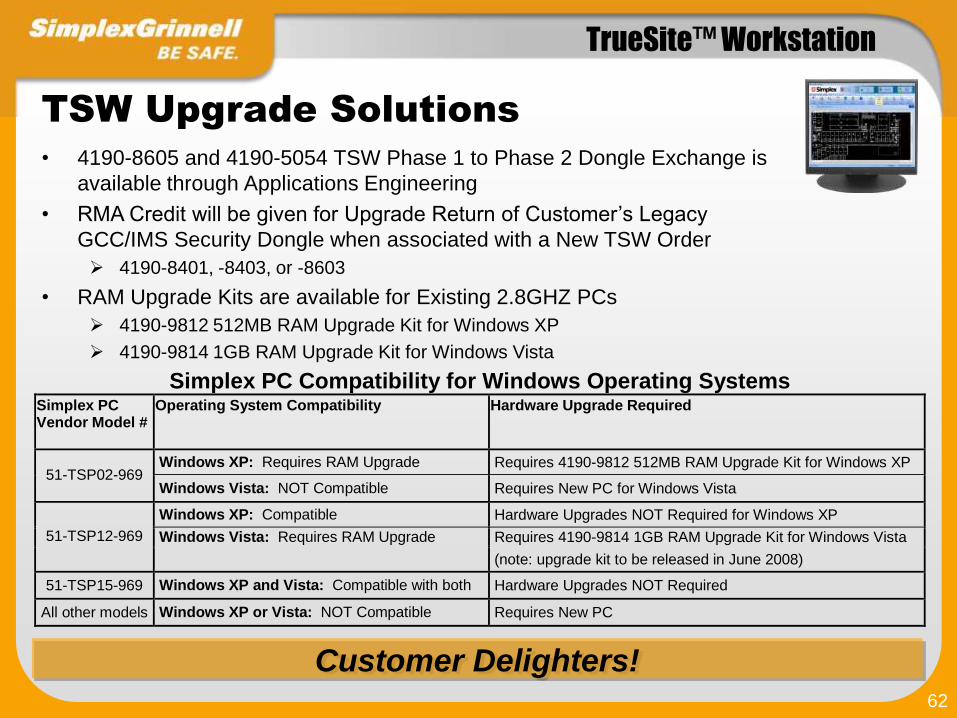
TSW Upgrade Solutions
• 4190-8605 and 4190-5054 TSW Phase 1 to Phase 2 Dongle Exchange is
available through Applications Engineering
• RMA Credit will be given for Upgrade Return of Customer’s Legacy
GCC/IMS Security Dongle when associated with a New TSW Order
4190-8401, -8403, or -8603
• RAM Upgrade Kits are available for Existing 2.8GHZ PCs
4190-9812 512MB RAM Upgrade Kit for Windows XP
4190-9814 1GB RAM Upgrade Kit for Windows Vista
Simplex PC Compatibility for Windows Operating Systems Simplex PC Vendor Model #
Operating System Compatibility Hardware Upgrade Required
Windows XP: Requires RAM Upgrade Requires 4190-9812 512MB RAM Upgrade Kit for Windows XP 51-TSP02-969
Windows Vista: NOT Compatible Requires New PC for Windows Vista
Windows XP: Compatible Hardware Upgrades NOT Required for Windows XP
Windows Vista: Requires RAM Upgrade Requires 4190-9814 1GB RAM Upgrade Kit for Windows Vista 51-TSP12-969
(note: upgrade kit to be released in June 2008)
51-TSP15-969 Windows XP and Vista: Compatible with both Hardware Upgrades NOT Required
All other models Windows XP or Vista: NOT Compatible Requires New PC
Customer Delighters!
TrueSite™ Workstation
63
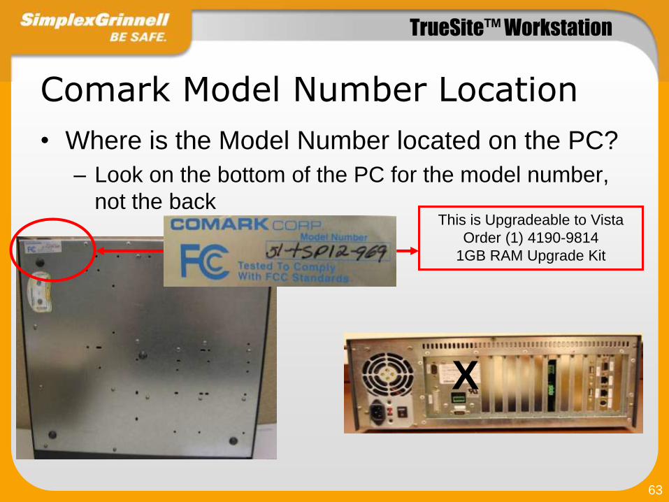
Comark Model Number Location
• Where is the Model Number located on the PC?
– Look on the bottom of the PC for the model number,
not the back
X
This is Upgradeable to Vista
Order (1) 4190-9814
1GB RAM Upgrade Kit

TrueSite™ Workstation
64
TSW Upgrade Solutions
TSW Upgrade Application and Programming Notes• When Upgrading an Existing GCC, IMS, or TSW Version 1 System with Graphics
to TSW Version 2 it is Strongly Recommended that All Client Monitors (local and
remote) be the same size as the original Monitor
– If a Standard (4:3) Monitor was used for the original screen programming, then a
Standard monitor is recommended for both local and remote clients with TSW Version 2
• If Widescreen Monitors are to be used on any Client (local or remote), for Upgraded
Screens that have Control Keys it is Strongly Recommended screens with Control
Keys be Reprogrammed so that the Control Keys are Placed in a Dedicated Non-
Zoomable Area of the Screen
• For All TSW Version 2 or later Systems, Control Keys and Non-Zoomable Objects
Must be Placed in a Dedicated Non-Zoomable Area of the Screen to Support Client
/ Server Systems that may use Multiple Style Monitors (standard and widescreen)

TrueSite™ Workstation
65
Ordering Information
Refer to Data Sheet S4190-0016 for latest information
To Review Click on the Document Icon

TrueSite™ Workstation
66
TSW Install Contents
Installation Package– Single file
– Option to install complete Server/Client or only Remote Client
.Net Framework (3.5 SP1)– Required by TSW
– Included on CD in case not already installed
MS Windows Installer– For XP
Instruction Manuals

TrueSite™ Workstation
67
TSW Documentation
• Updated Data Sheets are available on iPubs– S4190-0016 TrueSite Workstation
– S4190-0018 Ethernet Switches
– S4190-0011 Dot Matrix Event Printer
• The following technical publications are available on iPubs– 579-834 TSW Installation and Checkout Instructions
– 579-835 TSW Operation and Application Instructions
– 579-838 TSW Software Upgrade Instructions
– 579-844 TSW Configurator Reference Guide
– 579-878 TSW Quick Reference Card
– 579-888 TSW Service Parts List
– 579-889 TSW Guidelines for Order Writing & Graphic Screen AutoCAD Submittals
• Be sure to run SpecGen Update to get the Latest A&E Specs
Latest Tech Docs are Available on iPubs

TrueSite™ Workstation
68
Where’s The Value?
• Scalable, Cost Effective, Ethernet Network Connectivity for Multiple Remote
Client Workstations and Annunciator Terminals
Customer Focus + Innovative Features = Customer Value
• Leverages Customer’s Existing LAN / WAN Infrastructure for Remote Client
Annunciator Communications
• Protects Customer’s Investment and Life-Cycle Cost with GCC/IMS
Upgrade Packages and with Forward/Backward Compatibility to Existing
Simplex Fire Networks
• Increases Operator Efficiency through Improved Graphics and Rapid
Access to Information
• Intuitive Operation with Custom Action Messages allows Accelerated and
Accurate Response to Emergencies, Limits Customer Risks, and Reduces
Training Requirements

TrueSite™ Workstation
69
Where’s The Value?
• Agency Listed Seamless Integration of All Competitive and Legacy Systems
• Strengthens Protection of Life and Property through Centralized Life Safety
Information Management
• Extensive Historical Log Data can be Easily Accessed and Automatically
Archived Providing Peace-of-Mind and Reduced Liability
• Superior Technology: Remote Clients over Ethernet, Dynamic Pan-and-
Zoom Graphics, Extensive Information Management and Reporting, Peer-
to-Peer Network Survivability, Network Diagnostics, AutoCAD Compatible,
Graphic Screen AutoCAD Import/Export Capability, and more…)
Customer Focus + Innovative Features = Customer Value

TrueSite™ Workstation
70
Support Resources
Sales Engineering Support / Tyco Safety Products
• International Sales Engineering: Ed Arcikowski (978) 731-7510 or [email protected]
Technical Support / Tyco Safety Products
• Technical Support: (800) 363-6655 or [email protected]
Extranet Website:
• Log In: http://www.tycosafetyproducts-us.com
Training
• TSPI email: [email protected]
• TSPI Website: http://safetyproductstraining.com/
• TSW Version 2 Training Announcement

TrueSite™ Workstation
71
TrueSite™
Workstation
Common Version 1 and 2 Feature Review

TrueSite™ Workstation
72
Key TSW Features
Touchscreen or
Mouse User Control
Supports NEMA SB 30 Fire Service Annunciator and Interface Standard

TrueSite™ Workstation
73
UL/ULC/FM Proprietary Supervising Station Receiver Listings
(Requires Model 4190-8403)
Key TSW Features
UL, ULC, and CSFM Listed, FM Approved

TrueSite™ Workstation
74
Key TSW Features - Enhanced Graphics
Click and Drag
to ZOOM IN to
Graphics
IMS
Convert IMS
Graphic Files
to TrueSite
“Touch-Size”
feature hides
buttons when
operator is
zoomed out
Upgrade Path for Existing Customers

TrueSite™ Workstation
75
Enhanced TSW Graphics
Dual Monitor
Support
Multi-Monitor
Support“Coverage Zones”
Flash to Indicate Area
of Alarm
Superior Technology
Moveable Dockable
Window Panes

TrueSite™ Workstation
76
Enhanced TSW Graphics
Graphics
Extensive AutoCAD Compatibility with Import and Export

TrueSite™ Workstation
77
Dedicated or Multi-Tasking Operation
Graphics
Configurable for Captive or Non-Captive Operation
Multi-tasking Options

TrueSite™ Workstation
78
Alarm List Window
Immediate Access To Any And All Information
Sort-by-Column Information Management Efficiency

TrueSite™ Workstation
79
Point Status and Control Window
Monitor And Control with a Mouse Click

TrueSite™ Workstation
80
Graphics Window
Pan-and-Zoom Capabilities

TrueSite™ Workstation
81
Reports Window
Reports At Your Finger Tips

TrueSite™ Workstation
82
History and Operator Logging Window
Comprehensive Historical Archive

TrueSite™ Workstation
83
Network Window
Fast And Easy Diagnostic Tools

TrueSite™ Workstation
84
• The TSW provides a default banner bitmap (maximum size 1024x68 pixels)
with Simplex Logo
• A custom site-specific bitmap can be created which may be used to display
a corporate logo or other user preferred banner background
Custom Banner Background
Customer Delighter!

TrueSite™ Workstation
85
TSW supports a custom site-
specific bitmap which may be used
to display a corporate logo, facility
photograph and layout, or other
user preferred background image
(maximum size 1000x525 pixels)
Custom Main Screen Background
Customer Delighter!
TSW’s Default Main Screen Background

TrueSite™ Workstation
86
Key Features – Configurable
Inactivity Time-out
• TSW has an option for a configurable inactivity timer that
automatically logs out inactive users
• When no user is logged in, the TSW will provide view access with
limited control privileges. Login to the system will be required for
access to additional control operations.
Security Protection Against Unauthorized Use

TrueSite™ Workstation
87
Up to 8 2120s
Scalable Customer Solutions
Note: TSW Supports a Maximum of 7 PCI Style Option Cards (NIC, Quad Serial Card, etc.)
Supports Up to (8) 2120 SLI Connections

TrueSite™ Workstation
88
Compatible with Existing Simplex Networks, GCC and IMS
Key Features
Network Version Compatibility
4120 Network Interface
4190 GCC/IMS/NPU Master Version 2.07 (or later)
4100U Master Version 11.03 (or later)
4100 Master Version 9.02 (or later)
4020 Master Version 9.02 (or later)
4010 Master Version Master 3.01 (or later)
4002 Network Firmware Version 3.02.92 (or later)
2120 (SLI) Interface
2120 Version 5.44 (or later) Network Firmware Version 3.02 (or later)
4100 FIRE ALARM CONTROL
PULL TO OPEN DOOR
. .
P ULL TO OP E N DOOR
EMERG ENCY OPERATING
.
INSTRUCTIONS
. . . . .
ALA R M OR TR OU B LE C ON D I TION :
- S YSTEM I N D I C ATOR FLA SH IN G, TO N E ON .
TO A C K N OW LED GE :
- P R ES S "A C K " LO C ATED U N D ER FLA SH I N G
I N D I C ATO R .- R EPE AT OP E R ATI ON U N TIL A LL R EP OR TS A R E
A C KN OW LE D GED .
TO S ILEN C E A LA R M S I GN A LS :
- P R ES S "A LA R M S ILE N C E".
TO R E S TO R E SY STEM TO N O R M A L:- P R ES S "S YS TEM R ES ET."
- P R ES S "A C K " TO SI LEN C E TO N E D E VIC E.
OPERATOR
INTE RFA CE
PA NEL
ALAR M
AC K
FI R E
A LAR M
ACKNOW LEDGE
S Y STE M
TR OU BLE
S IGN ALS
SI LEN C ED
P OW E R
ON
S Y STE M
R ES E T
ALAR M
S ILEN C E
TBL
AC K
S U PV
AC K
P R IO R ITY 2
A LA R M
ALAR M
AC K
SY STEM
SU PE R V IS OR Y
ALLSPEAKERS
EVAC
WEATHER
WARNING
ALL
CLEAR
6TH FL
SPEAKERS
ALL
SPEAKERS
M ANUAL
AUDIO
OVERRIDE
PHONE
PAGING
LOCAL
SPEAKER
HO RN
CHIM E
SLOW
WHOOP
GSA
TONE
120 BPM
HORN
STUTTER
HI-LO
WAIL
FEM ALE
VO ICE
EVAC
BRITISH
EVAC
FRENCH /
ENGLISH
EVAC
SPANISH/
ENGLISH
EVAC
JAPANESE
EVAC
SECURITY BYPASS
WATCHTOUR
NIG HT
SENSITIVITY
PHONE
CIRCUIT
M EDICAL
EM ERGENCY
INDUSTRIAL
FIRE
CHEM ICAL
EM ERGENCY
HAZARDO US
M ATERIAL
VOICECO DE
3- 1-6-4
CHLORINE
LEAK
SYSTEM IS NORMAL
12:35:15 am MON 12 JUN 95
ALARM
ACK
4100U
Science Building 4020
Gymnasium
4100U
Engineering
NDU
Administration
& Finance
Physical Plant
FIRE ALARM
CONTROL
DISCONNECT
POWER BEFORE
SERVICING
CAUTION
** SYSTEM IS NORMAL ** 12:02:15pm Mon 9-Feb-98
SUPV
ACK
SYSTEMSUPERVISORY
ALARM
ACK
FIRE
ALARM
TROUBLE
ACK
SYSTEMTROUBLE
ALARM
SILENCE
ALARMSILENCED
SYSTEM
RESET
AC
POWER
4100 FIRE ALARM CONTROL
PULL TO OPEN DOOR
. .
P ULL TO OP E N DOOR
EMERG ENCY OPERATING
.
INSTRUCTIONS
. . . . .
ALA R M OR TR OU B LE C ON D I TION :
- S YSTEM I N D I C ATOR FLA SH IN G, TO N E ON .
TO A C K N OW LED GE :
- P R ES S "A C K " LO C ATED U N D ER FLA SH I N G
I N D I C ATO R .- R EPE AT OP E R ATI ON U N TIL A LL R EP OR TS A R E
A C KN OW LE D GED .
TO S ILEN C E A LA R M S I GN A LS :
- P R ES S "A LA R M S ILE N C E".
TO R E S TO R E SY STEM TO N O R M A L:- P R ES S "S YS TEM R ES ET."
- P R ES S "A C K " TO SI LEN C E TO N E D E VIC E.
OPERATOR
INTE RFA CE
PA NEL
ALAR M
AC K
FI R E
A LAR M
ACKNOW LEDGE
S Y STE M
TR OU BLE
S IGN ALS
SI LEN C ED
P OW E R
ON
S Y STE M
R ES E T
ALAR M
S ILEN C E
TBL
AC K
S U PV
AC K
P R IO R ITY 2
A LA R M
ALAR M
AC K
SY STEM
SU PE R V IS OR Y
ALLSPEAKERS
EVAC
WEATHER
WARNING
ALL
CLEAR
6TH FL
SPEAKERS
ALL
SPEAKERS
M ANUAL
AUDIO
OVERRIDE
PHONE
PAGING
LOCAL
SPEAKER
HO RN
CHIM E
SLOW
WHOOP
GSA
TONE
120 BPM
HORN
STUTTER
HI-LO
WAIL
FEM ALE
VO ICE
EVAC
BRITISH
EVAC
FRENCH /
ENGLISH
EVAC
SPANISH/
ENGLISH
EVAC
JAPANESE
EVAC
SECURITY BYPASS
WATCHTOUR
NIG HT
SENSITIVITY
PHONE
CIRCUIT
M EDICAL
EM ERGENCY
INDUSTRIAL
FIRE
CHEM ICAL
EM ERGENCY
HAZARDO US
M ATERIAL
VOICECO DE
3- 1-6-4
CHLORINE
LEAK
SYSTEM IS NORMAL
12:35:15 am MON 12 JUN 95
ALARM
ACK
4100 FIRE ALARM CONTROL
PULL TO OPEN DOOR
. .
P ULL TO OP E N DOOR
EMERG ENCY OPERATING
.
INSTRUCTIONS
. . . . .
ALA R M OR TR OU B LE C ON D I TION :
- S YSTEM I N D I C ATOR FLA SH IN G, TO N E ON .
TO A C K N OW LED GE :
- P R ES S "A C K " LO C ATED U N D ER FLA SH I N G
I N D I C ATO R .- R EPE AT OP E R ATI ON U N TIL A LL R EP OR TS A R E
A C KN OW LE D GED .
TO S ILEN C E A LA R M S I GN A LS :
- P R ES S "A LA R M S ILE N C E".
TO R E S TO R E SY STEM TO N O R M A L:- P R ES S "S YS TEM R ES ET."
- P R ES S "A C K " TO SI LEN C E TO N E D E VIC E.
OPERATOR
INTE RFA CE
PA NEL
ALAR M
AC K
FI R E
A LAR M
ACKNOW LEDGE
S Y STE M
TR OU BLE
S IGN ALS
SI LEN C ED
P OW E R
ON
S Y STE M
R ES E T
ALAR M
S ILEN C E
TBL
AC K
S U PV
AC K
P R IO R ITY 2
A LA R M
ALAR M
AC K
SY STEM
SU PE R V IS OR Y
ALLSPEAKERS
EVAC
WEATHER
WARNING
ALL
CLEAR
6TH FL
SPEAKERS
ALL
SPEAKERS
M ANUAL
AUDIO
OVERRIDE
PHONE
PAGING
LOCAL
SPEAKER
HO RN
CHIM E
SLOW
WHOOP
GSA
TONE
120 BPM
HORN
STUTTER
HI-LO
WAIL
FEM ALE
VO ICE
EVAC
BRITISH
EVAC
FRENCH /
ENGLISH
EVAC
SPANISH/
ENGLISH
EVAC
JAPANESE
EVAC
SECURITY BYPASS
WATCHTOUR
NIG HT
SENSITIVITY
PHONE
CIRCUIT
M EDICAL
EM ERGENCY
INDUSTRIAL
FIRE
CHEM ICAL
EM ERGENCY
HAZARDO US
M ATERIAL
VOICECO DE
3- 1-6-4
CHLORINE
LEAK
SYSTEM IS NORMAL
12:35:15 am MON 12 JUN 95
ALARM
ACK
4100 FIRE ALARM CONTROL
PULL TO OPEN DOOR
. .
P ULL TO OP E N DOOR
EMERG ENCY OPERATING
.
INSTRUCTIONS
. . . . .
ALA R M OR TR OU B LE C ON D I TION :
- S YSTEM I N D I C ATOR FLA SH IN G, TO N E ON .
TO A C K N OW LED GE :
- P R ES S "A C K " LO C ATED U N D ER FLA SH I N G
I N D I C ATO R .- R EPE AT OP E R ATI ON U N TIL A LL R EP OR TS A R E
A C KN OW LE D GED .
TO S ILEN C E A LA R M S I GN A LS :
- P R ES S "A LA R M S ILE N C E".
TO R E S TO R E SY STEM TO N O R M A L:- P R ES S "S YS TEM R ES ET."
- P R ES S "A C K " TO SI LEN C E TO N E D E VIC E.
OPERATOR
INTE RFA CE
PA NEL
ALAR M
AC K
FI R E
A LAR M
ACKNOW LEDGE
S Y STE M
TR OU BLE
S IGN ALS
SI LEN C ED
P OW E R
ON
S Y STE M
R ES E T
ALAR M
S ILEN C E
TBL
AC K
S U PV
AC K
P R IO R ITY 2
A LA R M
ALAR M
AC K
SY STEM
SU PE R V IS OR Y
ALLSPEAKERS
EVAC
WEATHER
WARNING
ALL
CLEAR
6TH FL
SPEAKERS
ALL
SPEAKERS
M ANUAL
AUDIO
OVERRIDE
PHONE
PAGING
LOCAL
SPEAKER
HO RN
CHIM E
SLOW
WHOOP
GSA
TONE
120 BPM
HORN
STUTTER
HI-LO
WAIL
FEM ALE
VO ICE
EVAC
BRITISH
EVAC
FRENCH /
ENGLISH
EVAC
SPANISH/
ENGLISH
EVAC
JAPANESE
EVAC
SECURITY BYPASS
WATCHTOUR
NIG HT
SENSITIVITY
PHONE
CIRCUIT
M EDICAL
EM ERGENCY
INDUSTRIAL
FIRE
CHEM ICAL
EM ERGENCY
HAZARDO US
M ATERIAL
VOICECO DE
3- 1-6-4
CHLORINE
LEAK
SYSTEM IS NORMAL
12:35:15 am MON 12 JUN 95
ALARM
ACK
4100 FIRE ALARM CONTROL
PULL TO OPEN DOOR
. .
P ULL TO OP E N DOOR
EMERG ENCY OPERATING
.
INSTRUCTIONS
. . . . .
ALA R M OR TR OU B LE C ON D I TION :
- S YSTEM I N D I C ATOR FLA SH IN G, TO N E ON .
TO A C K N OW LED GE :
- P R ES S "A C K " LO C ATED U N D ER FLA SH I N G
I N D I C ATO R .- R EPE AT OP E R ATI ON U N TIL A LL R EP OR TS A R E
A C KN OW LE D GED .
TO S ILEN C E A LA R M S I GN A LS :
- P R ES S "A LA R M S ILE N C E".
TO R E S TO R E SY STEM TO N O R M A L:- P R ES S "S YS TEM R ES ET."
- P R ES S "A C K " TO SI LEN C E TO N E D E VIC E.
OPERATOR
INTE RFA CE
PA NEL
ALAR M
AC K
FI R E
A LAR M
ACKNOW LEDGE
S Y STE M
TR OU BLE
S IGN ALS
SI LEN C ED
P OW E R
ON
S Y STE M
R ES E T
ALAR M
S ILEN C E
TBL
AC K
S U PV
AC K
P R IO R ITY 2
A LA R M
ALAR M
AC K
SY STEM
SU PE R V IS OR Y
ALLSPEAKERS
EVAC
WEATHER
WARNING
ALL
CLEAR
6TH FL
SPEAKERS
ALL
SPEAKERS
M ANUAL
AUDIO
OVERRIDE
PHONE
PAGING
LOCAL
SPEAKER
HO RN
CHIM E
SLOW
WHOOP
GSA
TONE
120 BPM
HORN
STUTTER
HI-LO
WAIL
FEM ALE
VO ICE
EVAC
BRITISH
EVAC
FRENCH /
ENGLISH
EVAC
SPANISH/
ENGLISH
EVAC
JAPANESE
EVAC
SECURITY BYPASS
WATCHTOUR
NIG HT
SENSITIVITY
PHONE
CIRCUIT
M EDICAL
EM ERGENCY
INDUSTRIAL
FIRE
CHEM ICAL
EM ERGENCY
HAZARDO US
M ATERIAL
VOICECO DE
3- 1-6-4
CHLORINE
LEAK
SYSTEM IS NORMAL
12:35:15 am MON 12 JUN 95
ALARM
ACK
4100 FIRE ALARM CONTROL
PULL TO OPEN DOOR
. .
P ULL TO OP E N DOOR
EMERG ENCY OPERATING
.
INSTRUCTIONS
. . . . .
ALA R M OR TR OU B LE C ON D I TION :
- S YSTEM I N D I C ATOR FLA SH IN G, TO N E ON .
TO A C K N OW LED GE :
- P R ES S "A C K " LO C ATED U N D ER FLA SH I N G
I N D I C ATO R .- R EPE AT OP E R ATI ON U N TIL A LL R EP OR TS A R E
A C KN OW LE D GED .
TO S ILEN C E A LA R M S I GN A LS :
- P R ES S "A LA R M S ILE N C E".
TO R E S TO R E SY STEM TO N O R M A L:- P R ES S "S YS TEM R ES ET."
- P R ES S "A C K " TO SI LEN C E TO N E D E VIC E.
OPERATOR
INTE RFA CE
PA NEL
ALAR M
AC K
FI R E
A LAR M
ACKNOW LEDGE
S Y STE M
TR OU BLE
S IGN ALS
SI LEN C ED
P OW E R
ON
S Y STE M
R ES E T
ALAR M
S ILEN C E
TBL
AC K
S U PV
AC K
P R IO R ITY 2
A LA R M
ALAR M
AC K
SY STEM
SU PE R V IS OR Y
ALLSPEAKERS
EVAC
WEATHER
WARNING
ALL
CLEAR
6TH FL
SPEAKERS
ALL
SPEAKERS
M ANUAL
AUDIO
OVERRIDE
PHONE
PAGING
LOCAL
SPEAKER
HO RN
CHIM E
SLOW
WHOOP
GSA
TONE
120 BPM
HORN
STUTTER
HI-LO
WAIL
FEM ALE
VO ICE
EVAC
BRITISH
EVAC
FRENCH /
ENGLISH
EVAC
SPANISH/
ENGLISH
EVAC
JAPANESE
EVAC
SECURITY BYPASS
WATCHTOUR
NIG HT
SENSITIVITY
PHONE
CIRCUIT
M EDICAL
EM ERGENCY
INDUSTRIAL
FIRE
CHEM ICAL
EM ERGENCY
HAZARDO US
M ATERIAL
VOICECO DE
3- 1-6-4
CHLORINE
LEAK
SYSTEM IS NORMAL
12:35:15 am MON 12 JUN 95
ALARM
ACK
4010
Library
4100
Dormitory A
4100
Education
TSW
Guard House
IMS

TrueSite™ Workstation
89
Key Features - Universal Integration
Solution
• Requires Compatible Sur-Gard, Bosch, or
AES Digital Alarm Communicating
Receiver
• DACR receives transmission from remote
panels
• TrueSite displays status on graphical maps
• Seamless integration of
multiple systems
• Agency-listed for ALL panels
Agency Listed Bridge for Integration of Multiple Systems
TSW
4100U or
4120 LOOP
DACR
RS-232

TrueSite™ Workstation
90
TSW DACR Interface Solutions
• Proprietary Receiving Station
– Simplex Fire Systems Network
• 4120, 4100U
– DACR Interface
• Sur-Gard System III or Bosch D6600
– Dial-In Telephone Service
– TCP/IP Communications
• Wireless RF Receiving Station
• AES - Intellinet® 7705i Receiver
• Requires TSW Version 1.01.04 or later
• Ref. Wireless Solutions
Cost Effective, Agency Listed, Systems Integration
Preserves Customer’s Investment
DACR / IPCR

TrueSite™ Workstation
91
• TSW’s DACR Interface integrates virtually ANY control equipment onto a Central
Workstation Command Center
• Unlike many competitive communication protocol interfaces, TSW’s DACR Interface is not
affected by software and protocol changes that may break compatibility and agency
compliance resulting from software upgrades to the control equipment being monitored
• Protocol interfaces often require ongoing protocol development necessary to maintain
compatibility with between equipment from different manufacturers and new versions of
software; thus, these interfaces are often difficult to manage, cost prohibitive, and a liability
risk to the building owner
• The Simplex TSW DACR Interface Solution ensures ongoing Agency Listing compliance
and virtually eliminates the ongoing maintenance and compliance cost associated with
standard protocol interfaces
TSW DACR Interface – Solution Benefits
Cost Effective, Risk Avoidance, Peace of Mind

TrueSite™ Workstation
92
AutoCAD Compatible Formats
Compatible Import Formats:
– DWG Formats: AutoCAD R9, 10, 11-12, 13, 14, 2000-2002, 2004-2006,
and 2007
– DXF AutoCAD R14 and 2000
Compatible Export Format:
– AutoCAD 2000 DWG/DXF Format (allows editing in AutoCAD 2000 or
later)
Editable TSW Configurator Entities
– Images have been Added to List of Editable TSW Configurator Entities
* Note: Images Must Originate from Bitmap File
AutoCAD Compatibility
Extensive AutoCAD Compatibility


