Transmission Grating Spectrometer for EUV
Lithography
Nathan Gray
Advisors: Alexander Shevelko, Larry Knight, and Scott Bergeson
Student Group Members: Matthew Harrison, Jeff Kemp, Bryce Allred, Jershon Lopez

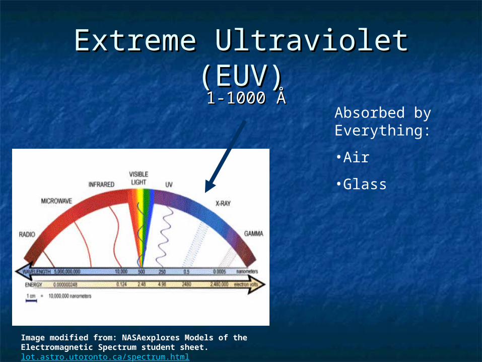
Extreme Ultraviolet (EUV)Extreme Ultraviolet (EUV)1-1000 1-1000 ÅÅ
Image modified from: NASAexplores Models of the Electromagnetic Spectrum student sheet. lot.astro.utoronto.ca/spectrum.html

Extreme Ultraviolet (EUV)Extreme Ultraviolet (EUV)1-1000 1-1000 ÅÅ
Image modified from: NASAexplores Models of the Electromagnetic Spectrum student sheet. lot.astro.utoronto.ca/spectrum.html
Absorbed by Everything:
•Air
Extreme Ultraviolet (EUV)Extreme Ultraviolet (EUV)1-1000 1-1000 ÅÅ
Image modified from: NASAexplores Models of the Electromagnetic Spectrum student sheet. lot.astro.utoronto.ca/spectrum.html
Absorbed by Everything:
•Air
•Glass

Extreme Ultraviolet (EUV)Extreme Ultraviolet (EUV)1-1000 1-1000 ÅÅ
Image modified from: NASAexplores Models of the Electromagnetic Spectrum student sheet. lot.astro.utoronto.ca/spectrum.html
Absorbed by Everything:
•Air
•Glass
•Plastic

Extreme Ultraviolet (EUV)Extreme Ultraviolet (EUV)1-1000 1-1000 ÅÅ
Image modified from: NASAexplores Models of the Electromagnetic Spectrum student sheet. lot.astro.utoronto.ca/spectrum.html
Absorbed by Everything:
•Air
•Glass
•Plastic
•Ponies

Extreme Ultraviolet (EUV)Extreme Ultraviolet (EUV)
Absorbed by Everything:
•Air
•Glass
•Plastic
Must operate under vacuum (our chamber is at 30-100 mtorr)
Must use mirrors in place of conventional optics.
This makes spectroscopy in the EUV range complicated.

EUV range transmission gratings:

EUV range transmission gratings:
Recent transmission grating development allows for EUV range gratings
200 nm period
(5000 lines/mm)

EUV range transmission gratings:
Recent transmission grating development allows for EUV range gratings
200 nm period
(5000 lines/mm)
Transmission grating spectrometers are superior to reflection grating spectrometers

Possible ConfigurationsPossible Configurations
Entrance SlitEntrance Slit
Grating
Detector
Simple Transmission Grating Spectrometer

Possible ConfigurationsPossible Configurations Single Mirror GeometrySingle Mirror Geometry
Entrance SlitEntrance Slit
Grating
Detector
Spherical Mirror
•High spectral resolution and luminosity
•Mirror collects large solid angle

Our ConfigurationsOur Configurations Double Mirror GeometryDouble Mirror Geometry
Grating
Entrance SlitEntrance SlitFlat Mirror
Detector
Spherical Mirror
Designed by Dr. Alexander Shevelko

Knight/Shevelko Group Knight/Shevelko Group Spectrometer ConfigurationSpectrometer Configuration

0
1000
2000
3000
4000
5000
6000
7000
8000
0 50 100 150 200
Wavelength (Ǻ)
Inte
ns
ity
(c
ou
nts
)
B
#002
EL=405 mJ
40 shot sum
Grating 5000 ℓ/mmEntrance Slit 250 μm
BV
1s-
2p 4
8.6
Ǻ
BIV
1s2 -1
s3p
52.7
Ǻ, 1s2 -1
s4p
50.4
Ǻ
BIV
1s2 -1
s2p
60.3
Ǻ
OV
I 2s
-4p 1
15.8
3Ǻ, 2p
-5d
115.
83Ǻ
OV
I 2p
-4d 1
29.8
Ǻ
OV
I 2p
-3d 1
73Ǻ
OV
I 2s
-3p 1
50.1
Ǻ

0
5000
10000
15000
20000
0 50 100 150 200
Wavelength (Ǻ)
Inte
ns
ity
(c
ou
nts
)
Fe
#006
EL=300 mJ
40 shot sum
Grating 5000 ℓ/mmEntrance Slit 250 μm
FeX-FeXI I IFeXVI 3d-5fFeXVI I 3s-4p
FeXVI 3s-4p
FeXV 3p-4dFeXVI 3p-4d
FeXIV 3p-4dFeXVI I 3d-4f
FeXV 3d-4f
FeXVI 3d-4f, FeXVI I 3d-4p

Electron Temperature StudyElectron Temperature StudyTungstenTungsten
0
500
1000
1500
2000
2500
3000
3500
4000
0 50 100 150 200 250 300
Wavelength (Ǻ)
Inte
ns
ity
(c
ou
nts
)
440mJ
300mJ
200mJ
150mJ
W
#024
Grating 5000 ℓ/mmEntrance Slit 250 μm
0
500
1000
1500
2000
2500
3000
3500
4000
0 50 100 150 200 250 300
Wavelength (Ǻ)
Inte
ns
ity
(c
ou
nts
)
W
#015
EL=440 mJ
1 shot
Grating 5000 ℓ/mmEntrance Slit 250 μm
WX
XII
-WX
XIX
4-5
tran
sition
s 25
-38
Ǻ
WXXVI I I -WXXX 4-4 transitions 48-65 Ǻ

Efficiency CalculationEfficiency Calculation
Major advantage of transmission grating over reflection grating
Must take transmission through wires into account (phase shift)
Materials:
Au 25 nm Au 25 nm
Si4N3 200 nm
Radiation
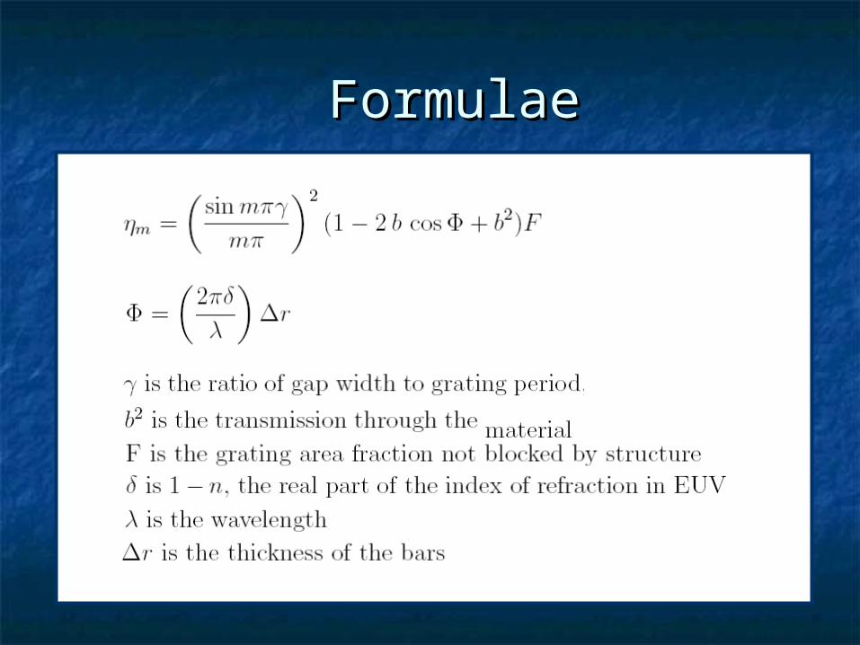
FormulaeFormulae

Efficiency CalculationEfficiency CalculationTotal Grating Efficiency
0
0.001
0.002
0.003
0.004
0.005
0.006
0 5 10 15 20 25 30 35 40 45
wavelength (nm)
Eff
icie
ncy
total efficiency
0
0.001
0.002
0.003
0.004
0.005
0.006
0 5 10 15 20 25 30 35 40 45
Fujikawa et al. MethodSchopper et al. Method
H. W. Schopper et al., Appl. Opt. 16, 1088 (1977).
C. Fujikawa et al., Rev. Sci. Instrum. 69, 2849 (1998).

Absolute CalibrationAbsolute Calibration
grating efficiency X spherical mirror reflectivity X flat mirror grating efficiency X spherical mirror reflectivity X flat mirror reflectivity reflectivity
= total spectrometer efficiency = total spectrometer efficiency

Absolute CalibrationAbsolute Calibration
grating efficiency X spherical mirror reflectivity X flat mirror grating efficiency X spherical mirror reflectivity X flat mirror reflectivity reflectivity
= total spectrometer efficiency = total spectrometer efficiency
total spectrometer efficiency X detector calibration total spectrometer efficiency X detector calibration
= absolute calibration= absolute calibration
absolute calibration = Intensity scaled to units of actual photon absolute calibration = Intensity scaled to units of actual photon flux, instead of just relative intensity.flux, instead of just relative intensity.
Detector calibration: completed at Lebedev Physical Institute by Oleg Yakushev

EUV LithographyEUV Lithography
International Technology Roadmap for Semiconductors printable patterns with 32 nm between features are required by the semiconductor industry by 2009
EUV LithographyEUV Lithography
Main limitation is wavelength of light source
Higher Resolution requires a source with smaller wavelength

V. Bakshi, EUV Sources for Lithography, SPIE Press Book, 2006.V. Bakshi, EUV Sources for Lithography, SPIE Press Book, 2006.
Typical EUV wafer scannerTypical EUV wafer scanner

EUV LithographyEUV Lithography
Typical EUV Lithography apparatus: 11 mirror multilayer Mo/Sn multilayer
mirrors with reflections around 66% each.
The overall transmission in the EUV scanner is less than 1%,
The mirrors reflect a bandwidth of 2% around a central wavelength of 135 °A.

EUV LithographyEUV Lithography
0
50
100
150
200
250
300
350
75 85 95 105 115 125 135 145 155 165 175
Wavelength (Ǻ)
Inte
ns
ity
(c
ou
nts
)
Li
#001
EL=425 mJ
1 shot
Grating 5000 ℓ/mmEntrance Slit 250 μm
Li I
II 1
s-4p
, 5p
Li I
II 1
s-3p
Li I I I 1s-2p
0
200
400
600
800
1000
1200
0 50 100 150 200 250 300
Wavelength (Ǻ)
Inte
ns
ity
(c
ou
nts
)
Sn
#025
EL=450 mJ
100 shot avg
Grating 5000 ℓ/mmEntrance Slit 250 μm
Sn (4d-4f) UTA
Source candidates: Lithium and Tin plasmas

EUV LithographyEUV Lithography
Mirror heatingMirror heating Unwanted radiationUnwanted radiation Target purityTarget purity Plasma parameters (electron Plasma parameters (electron
temperatures, absolute outputs, etc.)temperatures, absolute outputs, etc.)


Current WRS
Planned WRS with multiple gratings

AcknowledgementsAcknowledgements
Dr. ShevelkoDr. Shevelko Dr. KnightDr. Knight Matt Harrison and the other Matt Harrison and the other
members of my groupmembers of my group The chemists (especially Dr. Asplund)The chemists (especially Dr. Asplund)


