Download - Transformer Equipment - allbro.uk.com

8Transformer Equipment

206
Transformer Equipment Series
Rotary Tap SwitchesPg.218
Rotary Tap SwitchesPg.219
Rotary Tap SwitchesPg.220
Rotary Tap SwitchesPg.221
Linear Tap SwitchesPg.221
600VPg.207
1.1KvPg.208
1.1Kv Pg.208
3.6KvPg.209
12KvPg.209
24KvPg.210
36KvPg.210
Air-to-airPg.211
Cable boxPg.211
Rotary Tap SwitchesPg.217
Oil GaugesPg.223
Ball ValvePg.224
Brass PlugPg.224
Radiator ValvePg.224
Weld On BossPg.224
BreathersPg.225
Thermometers BM80Pg.227
Thermometers with ContactsPg.227
Thermometer F036Pg.228
Pocket Housing and Boss Assembly
Pg.228
Buchholz RelaysPg.229
Pressure Relief ValvePg.235
Magnetic Oil GaugesPg.238
Ball ValvePg.223
DINPg.212
ENPg.213
24KvPg.210
AUPg.214 - 215
Offset BushingsPg.216
Wildlife GuardsPg.216
Rotary Tap SwitchesPg.222

207
PART NUMBER DESCRIPTION Kv RATING CURRENT RATING MATERIAL TANK HOLE SIZE040-006 B6 0.6 45 PA6 Black Nylon 15
040-035 BS6 0.6 45 PA6 Black Nylon 12
040-007 B8 0.6 60 PA6 Black Nylon 21
040-008 B10 0.6 80 DMC 22
040-009 B12 0.6 120 DMC 25
040-025 NB6 0.6 45 DMC 19
040-026 NB8 0.6 60 DMC 19
040-034 NB8 - 3.3 3.3 60 DMC 19
040-027 NB10 0.6 80 DMC 22
600V Terminal Immersed Bushings
* Note: Detailed drawings available on request
Bushings
Transformer
Equipm
entLocks
Hinges
Accessories
Rotary O
peratingH
andlesE
nclosuresH
andlesIndex
Insulators
208
Tran
sfor
mer
E
quip
men
tLo
cks
Hin
ges
Acc
esso
ries
Rot
ary
Ope
ratin
gH
andl
esE
nclo
sure
sH
andl
esIn
dex
Insu
lato
rs
Bushings
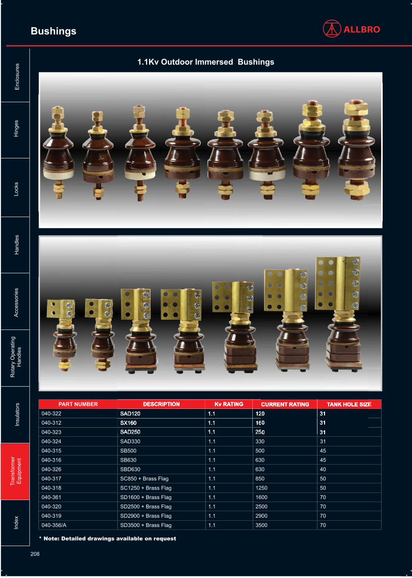
PART NUMBER DESCRIPTION Kv RATING CURRENT RATING TANK HOLE SIZE040-322 SAD120 1.1 120 31
040-312 SX160 1.1 160 31
040-323 SAD250 1.1 250 31
040-324 SAD330 1.1 330 31
040-315 SB500 1.1 500 45
040-316 SB630 1.1 630 45
040-326 SBD630 1.1 630 40
040-317 SC850 + Brass Flag 1.1 850 50
040-318 SC1250 + Brass Flag 1.1 1250 50
040-361 SD1600 + Brass Flag 1.1 1600 70
040-320 SD2500 + Brass Flag 1.1 2500 70
040-319 SD2900 + Brass Flag 1.1 2900 70
040-356/A SD3500 + Brass Flag 1.1 3500 70
CURRENT RATING TANK HOLE SIZE120 31
160 31
250 31
1.1Kv Outdoor Immersed Bushings
* Note: Detailed drawings available on request
DESCRIPTION Kv RATINGSAD120 1.1 120
SX160 1.1 160
SAD250 1.1 250
CURRENT RATING120
160
250
209
PART NUMBER DESCRIPTION Kv RATING CURRENT RATING TANK HOLE SIZE
CREEPAGE PER Kv(mm)
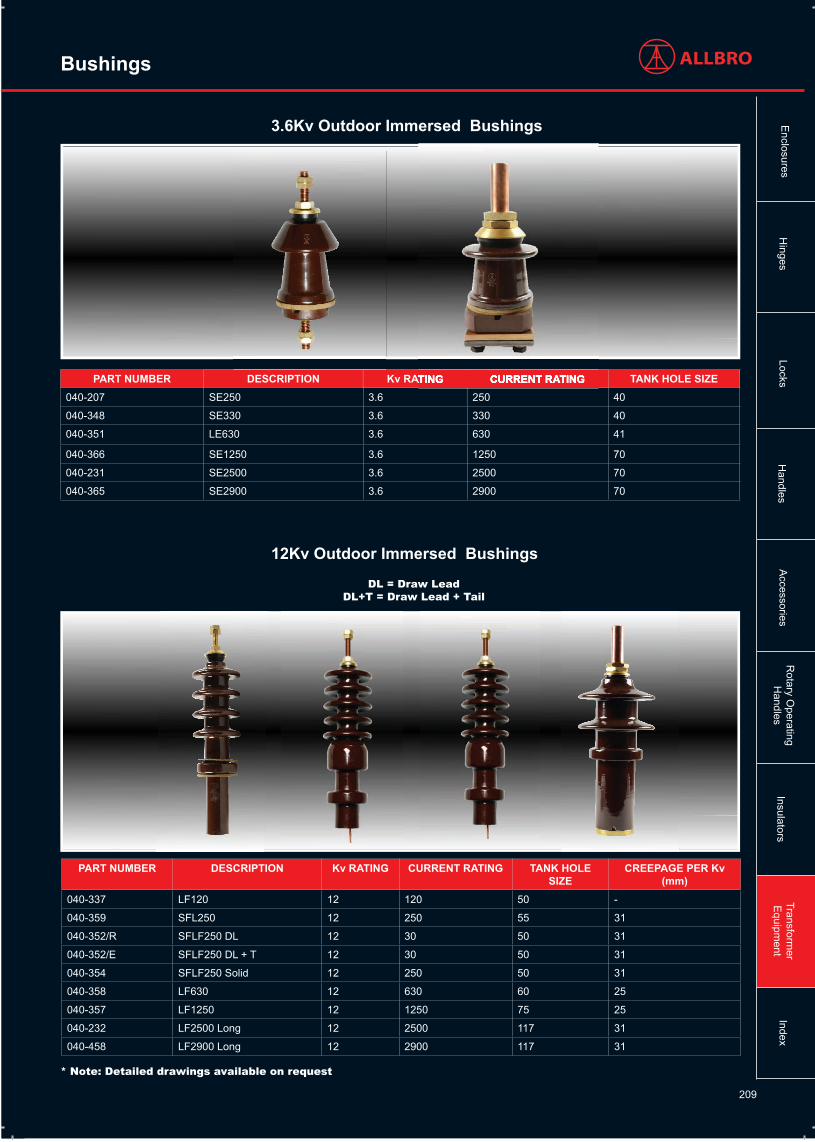
040-337 LF120 12 120 50 -
040-359 SFL250 12 250 55 31
040-352/R SFLF250 DL 12 30 50 31
040-352/E SFLF250 DL + T 12 30 50 31
040-354 SFLF250 Solid 12 250 50 31
040-358 LF630 12 630 60 25
040-357 LF1250 12 1250 75 25
040-232 LF2500 Long 12 2500 117 31
040-458 LF2900 Long 12 2900 117 31
PART NUMBER DESCRIPTION Kv RATING CURRENT RATING TANK HOLE SIZE040-207 SE250 3.6 250 40
040-348 SE330 3.6 330 40
040-351 LE630 3.6 630 41
040-366 SE1250 3.6 1250 70
040-231 SE2500 3.6 2500 70
040-365 SE2900 3.6 2900 70
Kv RATING CURRENT RATING
3.6Kv Outdoor Immersed Bushings
12Kv Outdoor Immersed Bushings
DL = Draw LeadDL+T = Draw Lead + Tail
* Note: Detailed drawings available on request
Bushings
Transformer
Equipm
entLocks
Hinges
Accessories
Rotary O
peratingH
andlesE
nclosuresH
andlesIndex
Insulators

210
Bushings
PART NUMBER DESCRIPTION Kv RATING CURRENT RATING TANK HOLE SIZE
CREEPAGE PER Kv(mm)
040-331 SG250 24 250 90 31
040-353 SGF250 DL 24 30 80 31
040-353/R SGF250 DL + T 24 30 80 31
040-355 SGF250 Solid 24 250 80 31
PART NUMBER DESCRIPTION Kv RATING CURRENT RATING
TANK HOLE SIZE
CREEPAGE IN mm PER Kv
040-222 LH250 DL + T 36 30 90 31
040-221 LHC250 36 250 90 31
040-341 LH630 36 630 90 31
040-342 LHC630 36 630 90 31
040-544 LH1250 Long DL 36 630 117 31
040-541 LH1250 Long 36 1250 117 31
040-545 LH1250 Long SR 36 1250 117 31
040-546 LH2500 Long DL 36 630 117 31
040-540 LH2500 Long 36 2500 117 31
040-547 LH2500 Long SR 36 2500 117 31
040-362 LJ250 48 250 90 31
24Kv Outdoor Immersed Bushings
36Kv Outdoor Immersed Bushings
DL = Draw LeadDL+T = Draw Lead + Tail
* Note: Detailed drawings available on request
Tran
sfor
mer
E
quip
men
tLo
cks
Hin
ges
Acc
esso
ries
Rot
ary
Ope
ratin
gH
andl
esE
nclo
sure
sH
andl
esIn
dex
Insu
lato
rs

211
Bushings
PART NUMBER DESCRIPTION Kv RATING(Um)
CURRENTRATING
TANK HOLE SIZE
PF - 60 SEC STEM DIAMETER
070-392 FB10 Flame Proof 1.1 80 21 7.5Kv M10
040-015 AA-062/250 7.2 250 50 18Kv M12
040-019 AA-062-630 7.2 630 50 18Kv M20
040-016 AA-112/250 12 250 50 30Kv M12
040-017 AA-112/630 12 630 50 30Kv M20
040-014 AA-113/250 12 250 50 30Kv M12
040-020 AA-113/630 12 630 50 30Kv M20
Air- to-air Type
* Note: Detailed drawings available on request
PART NUMBER DESCRIPTION Kv RATING(Um)
CURRENT RATING
TANK HOLE SIZE
BIL STEM DIAMETER
040-208 SM250 12Kv * 250 50 N/A M12
040-005 IM250 12Kv 250 50 N/A M12
040-032 CF1 22Kv 630 72 N/A OD=20 , Tapped M12
Cable Box Type
* 7.2Kv Outdoor Rating * Note: Detailed drawings available on request
Transformer
Equipm
entLocks
Hinges
Accessories
Rotary O
peratingH
andlesE
nclosuresH
andlesIndex
Insulators
212
Bushings
Tran
sfor
mer
E
quip
men
tLo
cks
Hin
ges
Acc
esso
ries
Rot
ary
Ope
ratin
gH
andl
esE
nclo
sure
sH
andl
esIn
dex
Insu
lato
rs
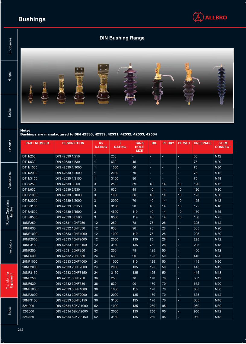
DIN Bushing Range
PART NUMBER DESCRIPTION Kv RATING
IRATING
TANK HOLE SIZE
BIL PF DRY PF WET CREEPAGE STEM CONNECT
DT 1/250 DIN 42530 1/250 1 250 - - - - 60 M12
DT 1/630 DIN 42530 1/630 1 630 45 - - - 75 M20
DT 1/1000 DIN 42530 1/1000 1 1000 56 - - - 75 M30
DT 1/2000 DIN 42530 1/2000 1 2000 70 - - - 75 M42
DT 1/3150 DIN 42530 1/3150 1 3150 90 - - - 75 M48
DT 3/250 DIN 42539 3/250 3 250 39 40 14 10 120 M12
DT 3/630 DIN 42539 3/630 3 630 45 40 14 10 120 M20
DT 3/1000 DIN 42539 3/1000 3 1000 56 40 14 10 125 M30
DT 3/2000 DIN 42539 3/2000 3 2000 70 40 14 10 125 M42
DT 3/3150 DIN 42539 3/3150 3 3150 90 40 14 10 125 M48
DT 3/4500 DIN 42539 3/4500 3 4500 119 40 14 10 130 M55
DT 3/6500 DIN 42539 3/6500 3 6500 119 40 14 10 130 M75
10NF250 DIN 42531 10NF250 12 250 78 75 28 - 305 M12
10NF630 DIN 42532 10NF630 12 630 90 75 28 - 305 M20
10NF1000 DIN 42533 10NF1000 12 1000 110 75 28 - 295 M30
10NF2000 DIN 42533 10NF2000 12 2000 135 75 28 - 295 M42
10NF3150 DIN 42533 10NF3150 12 3150 135 75 28 - 295 M48
20NF250 DIN 42531 20NF250 24 250 78 125 50 - 450 M12
20NF630 DIN 42532 20NF630 24 630 90 125 50 - 440 M20
20NF1000 DIN 42533 20NF1000 24 1000 110 125 50 - 445 M30
20NF2000 DIN 42533 20NF2000 24 2000 135 125 50 - 445 M42
20NF3150 DIN 42533 20NF3150 24 3150 135 125 50 - 445 M48
30NF250 DIN 42531 30NF250 36 250 78 170 70 - 607 M12
30NF630 DIN 42532 30NF630 36 630 90 170 70 - 662 M20
30NF1000 DIN 42533 30NF1000 36 1000 110 170 70 - 635 M30
30NF2000 DIN 42533 30NF2000 36 2000 135 170 70 - 635 M42
30NF3150 DIN 42533 30NF3150 36 3150 135 170 70 - 635 M48
52/1000 DIN 42534 52KV 1000 52 1000 135 250 95 - 950 M30
52/2000 DIN 42534 52KV 2000 52 2000 135 250 95 - 950 M42
52/3150 DIN 42534 52KV 3150 52 3150 135 250 95 - 950 M48
Note:Bushings are manufactured to DIN 42530, 42539, 42531, 42532, 42533, 42534

213
Bushings
Transformer
Equipm
entLocks
Hinges
Accessories
Rotary O
peratingH
andlesE
nclosuresH
andlesIndex
Insulators
EN Bushing Range
PART NUMBER DESCRIPTION Kv RATING
CURRENTRATING
TANK HOLE SIZE
BIL PF DRY PF WET CREEPAGE STEM CONNECT
EN 1/250 EN 50386 1/250 1.1 250 28 20 10 10 55 M12 / M12
EN 1/250 P EN 50386 1/250 P 1.1 250 28 20 10 10 55 M12 / 23x23x5
EN 1/630 EN 50386 1/630 1.1 630 45 20 10 10 55 M20 / M20
EN 1/630 P EN 50386 1/630 P 1.1 630 45 20 10 10 55 M20 / 32x32x9
EN 1/1250 EN 50386 1/1250 1.1 1250 56 20 10 10 75 M30 / 70 ø x 10
EN 1/1000 P EN 50386 1/1000 P 1.1 1000 56 20 10 10 75 M30 / 57x57x12
EN 1/1250 P EN 50386 1/1250 P 1.1 1250 56 20 10 10 75 M30 / 57x57x12
EN 1/2000 EN 50386 1/2000 1.1 2000 70 20 10 10 75 M42 / 100x100x15
EN 1/2000 P EN 50386 1/2000 P 1.1 2000 70 20 10 10 75 M42 / 80x30x15
EN 1/3150 EN 50386 1/3150 1.1 3150 90 20 10 10 75 M48 / 110x110x15
EN 1/3150 P EN 50386 1/3150 P 1.1 3150 90 20 10 10 75 M48 / 120x30x15
EN 1/4000 EN 50386 1/4000 1.1 4000 118 20 10 10 85 M55 / 160x160x24
EN 12/250 P2 EN 50180 12/250 P2 12 250 80 75 - 28 240 M12/M12
EN 12/250 P4 EN 50180 12/250 P4 12 250 80 75 - 28 372 M12/M12
EN 12/630 P2 EN 50180 12/630 P2 12 630 90 75 - 28 240 M20/M20
EN 12/630 P4 EN 50180 12/630 P4 12 630 90 75 - 28 372 M20/M20
EN 12/1250 P4 EN 50180 12/1250 P4 12 1250 110 75 - 28 372 M30/M30
EN 12/2000 P4 EN 50180 12/2000 P4 12 2000 135 75 - 28 372 M42/M42
EN 12/3150 P4 EN 50180 12/3150 P4 12 3150 135 75 - 28 372 M48/M48
EN 24/250 P2 EN 50180 24/250 P2 24 250 80 125 - 50 480 M12/M12
EN 24/250 P4 EN 50180 24/250 P4 24 250 80 125 - 50 744 M12/M12
EN 24/630 P2 EN 50180 24/630 P2 24 630 90 125 - 50 480 M20/M20
EN 24/630 P4 EN 50180 24/630 P4 24 630 90 125 - 50 744 M20/M20
EN 24/1250 P4 EN 50180 24/1250 P4 24 1250 110 125 - 50 744 M30/M30
EN 24/2000 P4 EN 50180 24/2000 P4 24 2000 135 125 - 50 744 M42/M42
EN 24/3150 P4 EN 50180 24/3150 P4 24 3150 135 125 - 50 744 M48/M48
EN 36/250 P2 EN 50180 36/250 P2 36 250 80 150 - 70 720 M12/M12
EN 36/250 P4 EN 50180 36/250 P4 36 250 80 150 - 70 1116 M12/M12
EN 36/630 P2 EN 50180 36/630 P2 36 630 90 150 - 70 720 M20/M20
EN 36/630 P4 EN 50180 36/630 P4 36 630 90 150 - 70 1116 M20/M20
EN 36/1250 P4 EN 50180 36/1250 P4 36 1250 110 150 - 70 1116 M30/M30
EN 36/2000 P4 EN 50180 36/2000 P4 36 2000 135 150 - 70 1116 M42/M42
EN 36/3150 P4 EN 50180 36/3150 P4 36 3150 135 150 - 70 1116 M48/M48
Note:Bushings are manufactured to EN50180 and EN50386

214
Bushings
AU LV Bushing Range
PART NUMBER DESCRIPTION Kv RATING CURRENT RATING
TANK HOLE SIZE
BIL PF CREEPAGE
040-369/X AU 0K6-120 1H14CU Bushing 600V 120A 29 10Kv 4Kv >70
040-369/XT1 AU 0K6-120 2H14CU Bushing 600V 120A 29 10Kv 4Kv >70
040-369/XA1 AU 0K6-120 1H11BR Bushing 600V 80A 29 10Kv 4Kv >70
040-369/XA2 AU 0K6-120 1H11CU Bushing 600V 120A 29 10Kv 4Kv >70
040-370/X AU 3K6-200 1H14 Bushing 3.6Kv 200A 48 40Kv 16Kv >105
040-370/XA1 AU 3K6-200 1H11 Bushing (A) 3.6Kv 200A 48 40Kv 16Kv >105
040-371/X AU 3K6-500 1H14 Bushing 3.6Kv 500A 48 40Kv 16Kv >105
040-371/XA1 AU 3K6-500 2H14 Bushing (A) 3.6Kv 500A 48 40Kv 16Kv >105
040-387/XE AU 3K6-800 1H14 Bushing (E) 3.6Kv 800A 79 40Kv 16Kv >115
040-375/X AU 3K6-300 Bushing 3.6Kv 300A 48 40Kv 16Kv >105
040-376/XW AU 3K6-1000 Bushing S1H14 Bushing (W) 3.6Kv 1000A 72 40Kv 16Kv >105
040-376/X AU 3K6-1050 1H22 Bushing 3.6Kv 1050A 79 40Kv 16Kv >115
040-376/XE AU 3K6-1050 1H14 Bushing 3.6Kv 1050A 79 40Kv 16Kv >115
040-376/XE2 AU 3K6-1050 2H14 Bushing (E) 3.6Kv 1050A 79 40Kv 16Kv >115
040-376/XA2 AU 3K6-1050 1H18 Bushing (A) 3.6Kv 1050A 79 40Kv 16Kv >115
040-379/XW AU 3K6-1400 1H14 Bushing (W) 3.6Kv 1400A 79 40Kv 16Kv >115
040-380/XW AU 3K6-1400 2H14 Bushing (W) 3.6Kv 1400A 79 40Kv 16Kv >115
040-381/XW AU 3K6-1400 2H14 Bushing (W-SP) 3.6Kv 1400A 79 40Kv 16Kv >115
040-381/XE AU 3K6-1400 2H14 Bushing (E) 3.6Kv 1400A 79 40Kv 16Kv >115
040-382/XW AU 3K6-1400 1H18 Bushing (W) 3.6Kv 1400A 79 40Kv 16Kv >115
040-383/XW AU 3K6-1400 2H18 Bushing (W) 3.6Kv 1400A 79 40Kv 16Kv >115
040-377/X AU 3K6-2000 4H14 Bushing 3.6Kv 2000A 79 40Kv 16Kv >115
040-377/XE AU 3K6-2000 4H14 Bushing (E) 3.6Kv 2000A 79 40Kv 16Kv >115
040-384/XW AU 3K6-2700 2H22 Bushing (W) 3.6Kv 2700A 92 40Kv 16Kv >120
040-388/XE AU 3K6-3150 2H22 Bushing (E) 3.6Kv 3150A 92 40Kv 16Kv >120
Tran
sfor
mer
E
quip
men
tLo
cks
Hin
ges
Acc
esso
ries
Rot
ary
Ope
ratin
gH
andl
esE
nclo
sure
sH
andl
esIn
dex
Insu
lato
rs

215
PART NUMBER DESCRIPTION Kv RATING CURRENT RATING
TANK HOLE SIZE
BIL PF CREEPAGE
040-372/X AU 12K-30 Bushing 12Kv 30A 71 75Kv 30Kv >410
040-372/XE AU 12K-30 CF Bushing (E) 12Kv 30A 71 75Kv 30Kv >410
040-372/XW AU 12K-30 Bushing (W) 12Kv 30A 71 75Kv 30Kv >410
040-385/XW AU 12K-300A 3S Bushing (W) 12Kv 300A 60 75Kv 30Kv >285
040-386/XE AU 12K-30A 4S-PF Bushing (E) 12Kv 30A 60 75Kv 30Kv >345
040-389/XE AU 12K-30A 4S-CF Bushing (E) 12Kv 30A 60 75Kv 30Kv >345
040-394/XE AU 12K-200 4S Bushing (E) 12Kv 200A 60 75Kv 30Kv >345
040-390/XW AU 12K-300A 4S Bushing (W) 12Kv 300A 60 75Kv 30Kv >345
040-391/XE AU 12K-160 CB Bushing (E) 12Kv 160A 60 75Kv 30Kv >160
040-393/XE AU 11K-160 Shrouded Bushing (E) 12Kv 160A 60 75Kv 30Kv >160
040-373/X AU 24K-30 Bushing 24Kv 30A 71 125Kv 50Kv >530
040-373/XE AU 24K-30 CF Bushing (E) 24Kv 30A 71 125Kv 50Kv >530
040-373/XW AU 24K-30 Bushing (W) 24Kv 30A 71 125Kv 50Kv >530
040-399/XW AU 24K-300 5S Bushing (W) 24Kv 300A 80 125Kv 50Kv >480
040-374/X AU 24K-30 XS Bushing 24Kv 30A 71 125Kv 50Kv >640
040-374/XW AU 24K-30 XS Bushing (W) 24Kv 30A 71 125Kv 50Kv >640
040-378/X AU 36K-30 Bushing 36Kv 30A 71 170Kv 70Kv >720
040-368/X AU 44KV-120 9S Bushing 44Kv 120A 80 170Kv 77Kv >1067
PART NUMBER DESCRIPTION Kv RATING CURRENT TANK HOLE BIL PF
Bushings
Transformer
Equipm
entLocks
Hinges
Accessories
Rotary O
peratingH
andlesE
nclosuresH
andlesIndex
Insulators
AU HV Bushing Range

216
Bushings
PART NUMBER DESCRIPTION Kv RATING CURRENT RATING
TANK HOLE SIZE
BIL PF CREEPAGE
040-395/X AU 12K-30 Offset Bushing 12Kv 30A 70 75Kv 30Kv >706
040-396/X AU 12K-30 Offset Bushing 12Kv 30A 70 75Kv 30Kv >660
040-397/X AU 36K-30 Offset Bushing 24Kv 30A 70 125Kv 50Kv >1036
040-398/X AU 36K-30 Offset Bushing 24Kv 30A 70 125Kv 50Kv >990
Kv RATING
12Kv
Tran
sfor
mer
E
quip
men
tLo
cks
Hin
ges
Acc
esso
ries
Rot
ary
Ope
ratin
gH
andl
esE
nclo
sure
sH
andl
esIn
dex
Insu
lato
rs
Wildlife Guards
PART NUMBER DESCRIPTIONWLG-140 Wildlife Guard Shed Mount - 136mm
WLG-230 Wildlife Guard Shed Mount - 116mm
The Wildlife Guards are optimized for wildlife protection on over-head distribution systems rated 25Kv and less. These guards are designed to mount securely between the first and second shed (nearest the high voltage terminal) on primary bushings and arresters.
Offset Bushings

217
Tap Switches
PART NUMBER DESCRIPTION Kv CURRENT PHASE TYPE BRACKET CONTACT040-522 RTS 22 Kv 100A 1Ph - Type A 22 100 1 A Steel Std
040-523 RTS 22 Kv 100A 1Ph - Type B 22 100 1 B Steel Std
040-508 BC RTS 22Kv 100A 3Ph - Type A / 90° / BC 22 100 3 A Steel Butterfly
040-505 RTS 22Kv 100A 3Ph - Type A / MB 22 100 3 A Moulded Std
040-528 RTS 22Kv 100A 3Ph - Type A 22 100 3 A Steel Std
040-530 RTS 22Kv 100A 3Ph - Type AB 22 100 3 AB Steel Std
040-530 BC RTS 22Kv 100A 3Ph - Type AB / BC 22 100 3 AB Steel Butterfly
040-506 BC RTS 22Kv 100A 3Ph - Type B / 90° / BC 22 100 3 B Steel Butterfly
040-501 RTS 22Kv 100A 3Ph - Type B / MB 22 100 3 B Moulded Std
040-527 RTS 22Kv 100A 3Ph - Type B 22 100 3 B Steel Std
Contact Arrangement Types
All Rotary Tap - Switches are available with two types of moving contacts as indicated below:
Standard Contact Arrangement Butterfly Contact Arrangement
Rotary Tap Switches
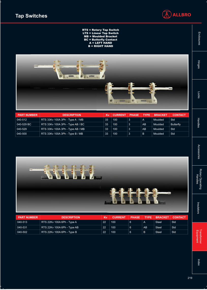
RTS = Rotary Tap SwitchLTS = Linear Tap SwitchMB = Moulded Bracket BC = Butterfly Contact
A = LEFT HANDB = RIGHT HAND
Transformer
Equipm
entLocks
Hinges
Accessories
Rotary O
peratingH
andlesE
nclosuresH
andlesIndex
Insulators

218
PART NUMBER
DESCRIPTION Kv CURRENT PHASE TYPE BRACKET CONTACT
040-534 RTS 22Kv 100A 3Ph ( 180 CNT ) Type AB 22 100 3 AB Steel Std
040-533 RTS 22Kv 100A 3Ph ( 270 CNT ) Type AB 22 100 3 AB Steel Std
040-532 RTS 22Kv 100A 3Ph ( 360 CNT ) Type AB 22 100 3 AB Steel Std
040-521 RTS 22Kv 100A 3Ph (180 CNT) Type A 22 100 3 A Steel Std
040-518 RTS 22Kv 100A 3Ph (180 CNT) Type B 22 100 3 B Steel Std
040-520 RTS 22Kv 100A 3Ph (270 CNT) Type A 22 100 3 A Steel Std
040-517 RTS 22Kv 100A 3Ph (270 CNT) Type B 22 100 3 B Steel Std
040-519 RTS 22Kv 100A 3Ph (360 CNT) Type A 22 100 3 A Steel Std
040-516 RTS 22Kv 100A 3Ph (360 CNT) Type B 22 100 3 B Steel Std
Tap Switches
RTS = Rotary Tap SwitchLTS = Linear Tap SwitchMB = Moulded Bracket BC = Butterfly Contact
A = LEFT HANDB = RIGHT HAND
Tran
sfor
mer
E
quip
men
tLo
cks
Hin
ges
Acc
esso
ries
Rot
ary
Ope
ratin
gH
andl
esE
nclo
sure
sH
andl
esIn
dex
Insu
lato
rs
219
Tap Switches
RTS = Rotary Tap SwitchLTS = Linear Tap SwitchMB = Moulded Bracket BC = Butterfly Contact
A = LEFT HANDB = RIGHT HAND
PART NUMBER DESCRIPTION Kv CURRENT PHASE TYPE BRACKET CONTACT040-512 RTS 33Kv 100A 3Ph - Type A / MB 33 100 3 A Moulded Std
040-529 BC RTS 33Kv 100A 3Ph - Type AB / BC 33 100 3 AB Moulded Butterfly
040-529 RTS 33Kv 100A 3Ph - Type AB / MB 33 100 3 AB Moulded Std
040-500 RTS 33Kv 100A 3Ph - Type B / MB 33 100 3 B Moulded Std
PART NUMBER DESCRIPTION Kv CURRENT PHASE TYPE BRACKET CONTACT040-513 RTS 22Kv 100A 6Ph - Type A 22 100 6 A Steel Std
040-531 RTS 22Kv 100A 6Ph - Type AB 22 100 6 AB Steel Std
040-502 RTS 22Kv 100A 6Ph - Type B 22 100 6 B Steel Std
Transformer
Equipm
entLocks
Hinges
Accessories
Rotary O
peratingH
andlesE
nclosuresH
andlesIndex
Insulators

220
Tap Switches
RTS = Rotary Tap SwitchLTS = Linear Tap SwitchMB = Moulded Bracket BC = Butterfly Contact
A = LEFT HANDB = RIGHT HAND
PART NUMBER DESCRIPTION Kv CURRENT PHASE TYPE BRACKET CONTACT040-509 BC RTS 22Kv 150A 3Ph - Type A / 90° / BC 22 150 3 A Steel Butterfly
040-510 BC RTS 22Kv 150A 3Ph - Type A / BC 22 150 3 A Steel Butterfly
040-511 BC RTS 22Kv 150A 3Ph - Type B / 90° / BC 22 150 3 B Steel Butterfly
040-507 BC RTS 22Kv 150A 3Ph - Type B / BC 22 150 3 B Steel Butterfly
PART NUMBER DESCRIPTION Kv CURRENT PHASE TYPE BRACKET CONTACT040-514 BC RTS 22Kv 300A 3Ph - Type A / BC 22 300 3 A Steel Butterfly
040-538 BC RTS 22Kv 300A 3Ph - Type AB / BC 22 300 3 AB Steel Butterfly
040-503 BC RTS 22Kv 300A 3Ph - Type B / BC 22 300 3 B Steel ButterflyTran
sfor
mer
E
quip
men
tLo
cks
Hin
ges
Acc
esso
ries
Rot
ary
Ope
ratin
gH
andl
esE
nclo
sure
sH
andl
esIn
dex
Insu
lato
rs

221
Tap Switches
SC = Slide ContactRTS = Rotary Tap SwitchLTS = Linear Tap SwitchMB = Moulded Bracket BC = Butterfly Contact
A = LEFT HANDB = RIGHT HAND
PART NUMBER DESCRIPTION Kv CURRENT PHASE TYPE BRACKET CONTACT040-543 RTS 88Kv 315A 3Ph - Type AB 88 315 3 AB Permali T - Type
040-542 RTS 88Kv 630A 3Ph - Type AB 88 630 3 AB Permali T - Type
PART NUMBER DESCRIPTION Kv CURRENT PHASE TYPE BRACKET CONTACT040-526 LTS 22Kv 30A 2Ph 5Pos 22 30 2 N/A Nylon Linear
040-525 LTS 22Kv 30A 3Ph 5Pos 22 30 3 N/A Nylon Linear
DESCRIPTION Kv CURRENT PHASE TYPE BRACKET CONTACT
Linear Tap Switches
Transformer
Equipm
entLocks
Hinges
Accessories
Rotary O
peratingH
andlesE
nclosuresH
andlesIndex
Insulators

222
Tap Switches
RTS = Rotary Tap SwitchLTS = Linear Tap SwitchMB = Moulded Bracket BC = Butterfly Contact
A = LEFT HANDB = RIGHT HAND
PART NUMBER DESCRIPTION Kv CURRENT PHASE TYPE BRACKET CONTACT040-580X RTS 33Kv 60A 1PH 7 POS - SC 33 60A 1 N/A N/A Slide
040-581X RTS 33Kv 60A 3PH 7 POS - SC 33 60A 3 N/A N/A Slide
040-585X RTS 33Kv 60A 1PH 7POS - RC/DP 33 60A 1 N/A N/A Slide
040-586X RTS 33Kv 60A 3PH 7POS - RC/DP 33 60A 3 N/A N/A Slide
PART NUMBER DESCRIPTION Kv CURRENT PHASE TYPE CONTACT040-582/X RTS 33Kv 60A 3Ph 7 POS - SC/SP 33 60A 3 AB Slide
040-583/X RTS 6.6Kv 60A 3Ph 7 POS - SC/SP 6.6 60A 3 AB Slide
040-584/X RTS 33Kv 60A 1Ph 7 POS - SC/SP 33 60A 1 AB Slide
Tran
sfor
mer
E
quip
men
tLo
cks
Hin
ges
Acc
esso
ries
Rot
ary
Ope
ratin
gH
andl
esE
nclo
sure
sH
andl
esIn
dex
Insu
lato
rs

223
Oil Gauges and Flags
PART NUMBER DESCRIPTION BOLT CENTERS TOTAL LENGHT LINE HEIGHTLOG-50 Oil Gauge 50 50 90 17
LOG-63 Oil Gauge 63 63 103 21
LOG-80 Oil Gauge 80 80 120 27
LOG-100 Oil Gauge 100 100 140 33
LOG-125 Oil Gauge 125 125 165 42
LOG-144 Oil Gauge 144 144 184 48
LOG-180 Oil Gauge 180 180 220 60
LOG-230 Oil Gauge 230 230 270 77
LOG-288 Oil Gauge 288 288 328 96
LOG-360 Oil Gauge 360 360 400 120
PART NUMBER DESCRIPTION TYPE FLAG HEIGHT HOLE SIZE010-077 SAD250 Flag Copper L Shape 110mm 13mm Diameter
010-078 SAD330 Flag Copper L Shape 110mm 15mm Diameter
010-079 SB 500 Flag Copper L Shape 110mm 19mm Diameter
010-080 SB 630 Flag Copper L Shape 110mm 21mm Diameter
010-003 SC850 /1250 Flag Brass “Y” Extrusion 60mm 21mm Diameter
010-088 SC1250 Flag Brass “Y” Extrusion 60mm 38mm Diameter
010-098 SD1600 Flag Brass “Y” Extrusion 100mm 27mm Diameter
010-004 SD2500 Flag Brass “Y” Extrusion 100mm 38mm Diameter
010-151 SD2900 Flag Brass “Y” Extrusion 135mm 38mm Diameter
010-076 SD3500 Flag Brass “Y” Extrusion 172mm 38mm Diameter
Transformer
Equipm
entLocks
Hinges
Accessories
Rotary O
peratingH
andlesE
nclosuresH
andlesIndex
Insulators

224
Valves
PART NUMBER DESCRIPTION021-402 0.5” Ball Valve Only (15mm)
021-403 0.5” Ball Valve Single Fixed Flange (15mm)
021-419 0.5” Ball Valve Single Rotating Flange (15mm)
021-409 0.5” Ball Valve Double Flange (15mm)
021-406 1” Ball Valve Only (25mm)
021-404 1” Ball Valve Single Fixed Flange (25mm)
021-420 1” Ball Valve Single Rotating Flange (25mm)
021-410 1” Ball Valve Double Flange (25mm)
PART NUMBER
DESCRIPTION ORI FACE ø
H L NO.OF
STUDS
STUD SIZE(mm)
STUPCD(mm)
STUDCTC(mm)
040-368 Radiator Valve 80x125
73mm 125 125 4 16 125 88
040-367 Radiator Valve 80x138
76mm 138 138 4 16 146 103
PART NUMBER DESCRIPTION THREAD002-059 0.5’’ Brass Plug 0.5’’ BSP
002-136 0.75’’ Brass Plug 0.75” BSP
002-055 1” Brass Plug 1” BSP
PART NUMBER DESCRIPTION ORIFACE ø
(mm)
H(mm)
THREAD
002-057 20mm Weld on Boss 20 30 M12
002-058 25mm Weld on Boss 25 30 M12
Tran
sfor
mer
E
quip
men
tLo
cks
Hin
ges
Acc
esso
ries
Rot
ary
Ope
ratin
gH
andl
esE
nclo
sure
sH
andl
esIn
dex
Insu
lato
rs

225
Breathers
PART NUMBER DESCRIPTION CAPACITY IN LITERS021-600 SA90 1600
021-601 SA100-1 2400
021-602 SA100-2 3800
021-603 SA100-3 5700
021-604 SA100-4 7600
021-605 SA100-5 9600
021-606 SA100-6 11600
Silica Gel:The breathers contain the latest EU & ESKOM specified grade of gel.
PART NUMBER DESCRIPTION001-056 Blue Silica Dehydrating Beads (per kg)
001-306 Amber Silica Dehydrating Beads (per kg)
Amber Silica Dehydrating Beads Blue Silica Dehydrating Beads
Transformer
Equipm
entLocks
Hinges
Accessories
Rotary O
peratingH
andlesE
nclosuresH
andlesIndex
Insulators

226
Buchholz Relay
Pressure Relief Valves
Magnetic Oil Gauge
Thermometers
Protection Equipment
Tran
sfor
mer
E
quip
men
tLo
cks
Hin
ges
Acc
esso
ries
Rot
ary
Ope
ratin
gH
andl
esE
nclo
sure
sH
andl
esIn
dex
Insu
lato
rs
227
Thermometers
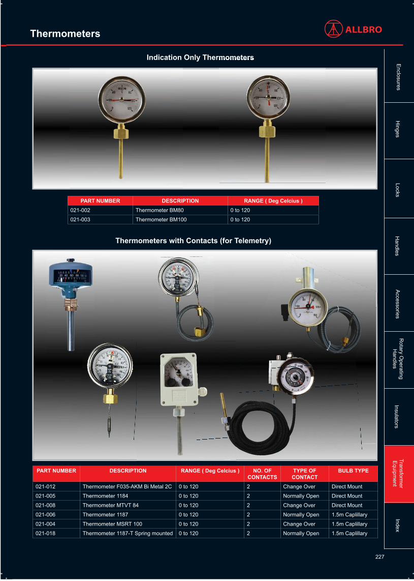
Indication Only Thermometers
Thermometers with Contacts (for Telemetry)
Indication Only Thermometers
PART NUMBER DESCRIPTION RANGE ( Deg Celcius )021-002 Thermometer BM80 0 to 120
021-003 Thermometer BM100 0 to 120
PART NUMBER DESCRIPTION RANGE ( Deg Celcius ) NO. OF CONTACTS
TYPE OF CONTACT
BULB TYPE
021-012 Thermometer F035-AKM Bi Metal 2C 0 to 120 2 Change Over Direct Mount
021-005 Thermometer 1184 0 to 120 2 Normally Open Direct Mount
021-008 Thermometer MTVT 84 0 to 120 2 Change Over Direct Mount
021-006 Thermometer 1187 0 to 120 2 Normally Open 1.5m Caplillary
021-004 Thermometer MSRT 100 0 to 120 2 Change Over 1.5m Caplillary
021-018 Thermometer 1187-T Spring mounted 0 to 120 2 Normally Open 1.5m Caplillary
Transformer
Equipm
entLocks
Hinges
Accessories
Rotary O
peratingH
andlesE
nclosuresH
andlesIndex
Insulators
228
Thermometers
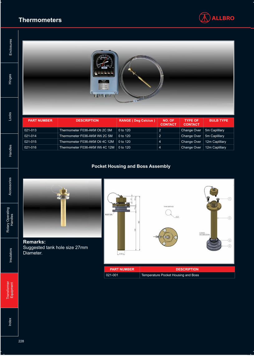
PART NUMBER DESCRIPTION021-001 Temperature Pocket Housing and Boss
Remarks: Suggested tank hole size 27mm Diameter.
PART NUMBER DESCRIPTION RANGE ( Deg Celcius ) NO. OF CONTACT
TYPE OF CONTACT
BULB TYPE
021-013 Thermometer F036-AKM Oti 2C 5M 0 to 120 2 Change Over 5m Caplillary
021-014 Thermometer F036-AKM Wti 2C 5M 0 to 120 2 Change Over 5m Caplillary
021-015 Thermometer F036-AKM Oti 4C 12M 0 to 120 4 Change Over 12m Caplillary
021-016 Thermometer F036-AKM Wti 4C 12M 0 to 120 4 Change Over 12m Caplillary
Pocket Housing and Boss Assembly
Tran
sfor
mer
E
quip
men
tLo
cks
Hin
ges
Acc
esso
ries
Rot
ary
Ope
ratin
gH
andl
esE
nclo
sure
sH
andl
esIn
dex
Insu
lato
rs
229
Buchholz Relays
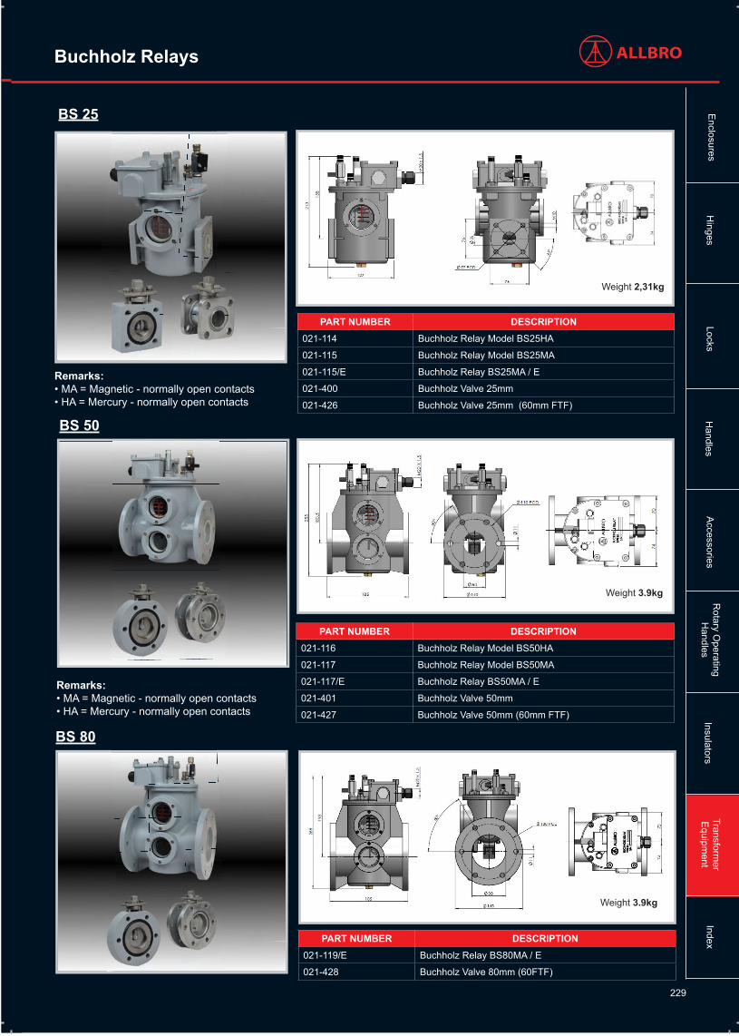
PART NUMBER DESCRIPTION021-114 Buchholz Relay Model BS25HA
021-115 Buchholz Relay Model BS25MA
021-115/E Buchholz Relay BS25MA / E
021-400 Buchholz Valve 25mm
021-426 Buchholz Valve 25mm (60mm FTF)
Remarks:• MA = Magnetic - normally open contacts• HA = Mercury - normally open contacts
Weight 2,31kg
PART NUMBER DESCRIPTION021-116 Buchholz Relay Model BS50HA
021-117 Buchholz Relay Model BS50MA
021-117/E Buchholz Relay BS50MA / E
021-401 Buchholz Valve 50mm
021-427 Buchholz Valve 50mm (60mm FTF)
Remarks:• MA = Magnetic - normally open contacts• HA = Mercury - normally open contacts
Weight 3.9kg
PART NUMBER DESCRIPTION021-119/E Buchholz Relay BS80MA / E
021-428 Buchholz Valve 80mm (60FTF)
BS 25
BS 50
BS 80
Weight 3.9kg
Transformer
Equipm
entLocks
Hinges
Accessories
Rotary O
peratingH
andlesE
nclosuresH
andlesIndex
Insulators

230
Buchholz Relays
The generation of gas in an oil filled transformer is a clear indication of a problem. The gas may be a result of the following:
• Decomposition / degradation of solid , or liquid insulation inside the transformer due to overheating, or arcing.• From the outside towards the pipeline.• From the oil itself due to unsatisfactory de-gassing prior to filling.
Rapid oil movement in the pipeline towards the conservator is caused by an internal arc, short circuit, or hot spot which must be correctely addressed.
Oil leaks from the transformer are environmentally unacceptable and a fire hazard will lead to transformer failure.
To indicate any of the above malfunctions we have developed a Buchholz relay to comply fully with the latest CENELEC EN 50216-1 and EN 50216-2 standards.
The relay incorporates the very latest technology in its construction.
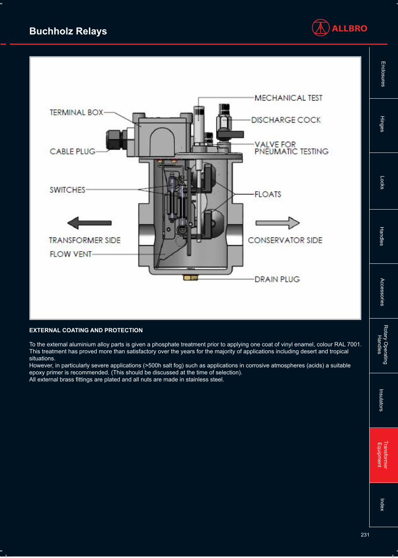
PRINCIPAL OF OPERATION
The Buchholz relay is sited in the pipework between the transformer and its conservator and it is filled with oil during normal transformer operation. When gas is generated in the transformer it rises towards the conservator and collects in the upper chamber of the relay.The oil level drops and the top float triggers alarm switch.
Gas shall not freely pass from the relay body and escape into the pipework before the alarm contact has operated. The trip contact shall operate at a steady oil flow as indicated in Table 3.
This operation shall not be adversely affected when the alarm contact has already closed and gas is escaping freely. In the event of an oil leak the Buchholz relay will only operate after the conservator has exhausted all of its oil. In order to check this eventually it is recommended that an RDR MK II automatic shutter valve is fitted between the Buchholz and the conservator.
Specific information on this product are available on request.
CONSTRUCTION
The Buchholz relay is an assembly of two machined aluminium alloy castings that effect a perfect oil seal.
1) The main body of the relay is fitted with tempered glass inspection windows with graduated scale markings in cubic centimeters to indicate the internal volume. The oil drain plug is located at the bottom of the main body. 2) The top cover carries the frame which contains the moving parts of the relay. These comprise the two floats and their associated switches encapsulated in glass bulbs, one calibrated flow valve and two permanent magnets.
The cover carries:
(4) a gas discharge valve with G1/8” in male thread with protective cap.(5) A valve for pneumatically testing the alarm and insulation circuits, with protective cap.(2) A push rod for mechanically tripping the alarm and the insulation circuits, with protective cap.
A terminal box which as standard contains 4 numbered M6 terminals and one earth terminal.
Tran
sfor
mer
E
quip
men
tLo
cks
Hin
ges
Acc
esso
ries
Rot
ary
Ope
ratin
gH
andl
esE
nclo
sure
sH
andl
esIn
dex
Insu
lato
rs
231
Buchholz Relays
EXTERNAL COATING AND PROTECTION
To the external aluminium alloy parts is given a phosphate treatment prior to applying one coat of vinyl enamel, colour RAL 7001.This treatment has proved more than satisfactory over the years for the majority of applications including desert and tropical situations.However, in particularly severe applications (>500h salt fog) such as applications in corrosive atmospheres (acids) a suitableepoxy primer is recommended. (This should be discussed at the time of selection).All external brass fittings are plated and all nuts are made in stainless steel.
Transformer
Equipm
entLocks
Hinges
Accessories
Rotary O
peratingH
andlesE
nclosuresH
andlesIndex
Insulators

232
Buchholz Relays
RELAY SELECTION
The size and type of relay to be used will depend on the transformer rating and oil volume. Suggestions are given in the following table but the final choice is often as a result of the transformer manufacturers experience.
MVA TRANSFORMER POWER NOMINAL DIAMETERUp to 5 25
From 5 up to 20 50
From 20 to 50 80
TECHNICAL DATA
• The relay pipework is typically mounted at 2,5 degrees to the horizontal. A positive inclination of up to 5 degrees to the horizontal axis is admissible.• Operating pressure - 1 bar, tested to 2,5 bar for 2 minutes at 100 deg C.• Gas volume to trip alarm:
BUCHHOLTZ RELAY TYPE GAS VOLUME NECESSARY TO TRIP THE ALARMBS 25 170÷230
BS 50, BS 80 250÷300
• Rate of oil flow in m/s to trip insulation. In the following table standard values are highlighted with an ‘O’ available, on request with an ‘X’ and not available with a ‘//’. +/- 15% tolerance at 20°C with oil viscosity according to IEC296.
INSIDE PIPE DIAMETER 1,0 m/s 1,5 m/s 2,0 m/s25 o x x
50 o x x
80 o x x
• The relay operates within 0,5 seconds.• Oil temperature between -25 and +115 deg C.• Ambient temperature between -25 and +60 deg C.• Degree of Protection IP65 to EN 60529.
SWITCH ELECTRICAL DATA
Rated switch current is 2 A r.m.s. with max. 10 A r.m.s. as short term 30 ms current value.Breaking power is specified in the following table:
VOLTAGE CURRENT BREAKING POWER
220 Vd.c. (min. 12V) 2 A for 10000 maneuvers 250 W
230 V a.c. (min.12V) 6 A for 1000 maneuvers 400 VA
Dielectric contact voltage as specified in the following table:
SHORT TERM INDUSTRIAL FREQUENCY LEAKAGE TEST
Kv / 1min. (r.m.s)
RESISTANCE VOLTAGE PER PULSE
Kv (peak)Between circuits and ground 2.5 5
Across open contacts 1 3
Tran
sfor
mer
E
quip
men
tLo
cks
Hin
ges
Acc
esso
ries
Rot
ary
Ope
ratin
gH
andl
esE
nclo
sure
sH
andl
esIn
dex
Insu
lato
rs

233
Buchholz Relays
The following Type Tests have been performed on the relay.
• Measurement of the volume of gas necessary to trip the alarm.• 500 hr salt fog.• Electromagnetic Field Test. Relay does not trip in field strength up to 25 mT (ref EN 50216-2).• Stationary sinusoidal mechanical vibrations. Tests according to EN 60721-3-4 standards have been performed. a) class 4M4 (4M6 on request) vibration test applied in sites where vibrations are transmitted from machinery and vehicles. Not suitable for machines exposed to high vibration and shock levels. Three-axis movement was impressed to the relay using special equipment with stationary sinusoidal vibrations from 2 to 200 Hz. Movement had a constant 3 mm (6 mm peak-peak) amplitude in the range from 2 to 9 Hz whereas above this frequency it had constant 10 m/s2 acceleration. The alarm and release switches did not trip.b) non-stationary vibration tests with vertical shock with 100 m/s2 acceleration with type I spectrum (duration 11 ms) as shown in the graph below. Alarm and release contacts did not trip. On demand we are able to manufacture Buchholz relays with special features and test values higher than the ones stated above.
• A seismic test was also performed according to EN 50216-1 standards that refers to EN 60068-3-3 class 0, level 2 standards.The test consists of application of a 9 m/s2 horizontal acceleration and a 4.5 m/s2 vertical acceleration, increasing frequency one octave per minute. No activation of alarm or release switches was encountered.• Pressure Withstand Test 2.5 bar for 2 minutes with oil at 100 deg C.• Vacuum Withstand Test of 2500 Pa for 24 hrs.• Rate of oil flow test to operate trip contcts, (as shown in table 3).• Test to show the relay is insensitive to oil flow from conservator to transformer.• Electrical tests per table 5.
ROUTINE TESTS
The following Routine Tests are applied to all relays.• Hydraulic seal test in mineral oil at 90 deg C and 100 kpa pressure for 30 minutes.• Contact operation via mechanical push rod.• Contact operation by lowering the oil.• Rate of oil flow to trip contacts.• Electrical withstand test between contacts (as table 5).• Electrical withstand test between contacts and earth (as table 5).An individual routine Test Report is shipped with each relay
RELAY OPERATING TEST
The following site Tests can be performed when the relay is installed on the transformer:The Alarm and Trip contacts can be tested manually by the push rod (2) - mechanical test, or (only for alarm contact) by the introduction of air into the relay through valve (5) - pneumatic test.A bicycle pump can be utilised for this test.To effectively test the rate of flow of oil is a complex test requiring specialised equipment. Should this test be required other than as a type test then we can perform this on request at the time of the order.
Transformer
Equipm
entLocks
Hinges
Accessories
Rotary O
peratingH
andlesE
nclosuresH
andlesIndex
Insulators

234
Buchholz Relays
INSTALLATION INSTRUCTIONS
The following installation procedures must be observed for proper relay operation:
• The red arrow on the relay must point towards the conservator.• The relay must always be full of oil, which means that the minimun oil level in the conservator must be higher than the relays breather valve.• The recommended inclination of the relay pipework is 2.5 degrees from the horizontal.• The pipe from the transformer to the relay must exit the transformer at the highest point.• The pipeline upstream from the relay has to be straight and with a length equal to 5-10 times the pipeline diameter, at least.
Down stream from the relay, pipeline length has to be 3 times the pipeline diameter, only. It must rise up towards the conservator.
Tran
sfor
mer
E
quip
men
tLo
cks
Hin
ges
Acc
esso
ries
Rot
ary
Ope
ratin
gH
andl
esE
nclo
sure
sH
andl
esIn
dex
Insu
lato
rs

235
Pressure Relief Valves
PART NUMBER DESCRIPTION Operating Pressure
Maximum Capacity
Switch I max
Switch V max
Switch Config
021-200 T50 Pressure Relief Valve 70Kpa 3000 L 5A 500VAC 1 C / Over
021-201 T80 Pressure Relief Valve 70Kpa 9000 L 5A 500VAC 1 C / Over
T50
T80
Remarks:We can set T50 and T80 devices to the following pressures on request: 55Kpa, 90Kpa, 125Kpa
Transformer
Equipm
entLocks
Hinges
Accessories
Rotary O
peratingH
andlesE
nclosuresH
andlesIndex
Insulators

236
ALLBRO “T” valves are used to control pressures inside tanks. They are used where accidental, instantaneous and uncontrolled increases in pressure may create the danger of explosion. They are designed to discharge the pressure increases that have taken place to the exterior in a very short time period (a few thousandths of a second). They are widely used in the metal tanks of oil-cooled electric transformers. Sudden and violent short circuits inside these tanks, in fact, instantly generate an enormous amount of gas with a great increase in interior pressures. If the pressure cannot discharge to the exterior there is danger that the transformer may explode, with all the possible harm and damages this may cause. This danger can be prevented by installing one or more valves with discharge sizes proportional to the volume of oil contained in the transformer. It is always good practice to install these valves in all situations where internal pressure values must not exceed specific safety limits.
CONSTRUCTION
Our valves are totally protected against external corrosion and against penetration of foreignbodies between cover and protective cap. This ensures perfect operating efficiency even forextended periods of time.
Pressure Relief Valves
TYPE “T” VALVES
These consist of a flanged body and a corrosion-proof aluminium alloy disk. A brass rod that holds the spring is applied to the central part of the disk. There are two gaskets in the valve: a special shaped upper gasket and a lip seal.
When the valve is closed the upper gasket is pressed against the disk. The shape of the gasket permits a perfect seal even if the disk lifts 1-2 mm. The disk also makes a seal against the lip seal gasket as it moves upwards. If, due to interior pressure, the disk rises beyond this amount then the upper seal is no longer maintained while the lip seal remains. At this instant the surface of the washer invested by internal pressure is multiplied in area as is the total force applied on the spring. This causes total and instantaneous opening of the valve which consequently discharges excess pressures to the exterior. When pressure has been discharged the disk, pushed back by the spring, lowers down and closes the valve. As the disk moves downwards it first closes against the side gasket and then against the upper gasket. This latter gasket, because of its special shape, is pressed down 1-2 mm. and the disk moves further down, breaking the seal on the lip seal gasket. This releases any pressure that mayhave been trapped between the two gaskets. Now the valve is ready to intervene again.
Total valve opening
Valve opening is total each time the valve operates for pressure settings between 20 and 90kPa. The discharge opening area, for each valve operation, is equal to that for higher pressure settings even when pressure settings are lower than 20 kPa. If, however, pressures are generated inside the tank that are much higher than the setting then the spring, furthercompressed, allows the closing disk to create even larger discharge areas when it operates.
Operating performance
Nominal operating pressure: the pre-fixed overpressure value shall be agreed between supplier and purchaser within the standard range from 20 up to 90 kPa, with 10 kPa steps,with a tolerance of - 5 kPa to + 7 kPa.
Routine tests
It is necessary to carry on operational tests, with compressed air:· to check the correct functioning of the device at the operating pressure value· to check the functioning of the optic signal and of the electric contacts.
INSTALLATION GUIDELINES
Our valves come in 2 sizes and have different discharge areas. This allows users to select the type that is best suited for the volume of oil contained in the tank. The following gives guideline values:
Volume of oil tank: Type of valveup to 3000 dm3 50 T*up to 9000 dm3 80 T*
* These guideline sizes are based on experience.
We recommend using multiple valves when oil volumes exceed these levels. It is always good practice to use multiple valves with smaller discharge areas rather than a single valve with a large area. The reason for this, in the case of transformers, is that it is better to install one valve above each winding column since these are the points where maximum interior pressures are generated in case of a short circuit. Instantaneous valve opening implies direct contact between the closing disk and oil. For this reason the valves are equipped with a screw to bleed out air that may accumulate during oil tank filling procedures.
Tran
sfor
mer
E
quip
men
tLo
cks
Hin
ges
Acc
esso
ries
Rot
ary
Ope
ratin
gH
andl
esE
nclo
sure
sH
andl
esIn
dex
Insu
lato
rs

237
Pressure Relief Valves
PRESSURE SETTINGS
Standard pressure settings, for each type of valve, may vary from 20 to 90 kPa(approximately 0.2-0.9 Atm.).Valves with non-standard pressure settings are manufactured on request.
GUARD AGAINST JETS OF HOT OIL
It is good practice, to prevent harm to persons or property from violent jets of hot oil evacuating from the valve, for valve discharges to be directed towards points properly designed to receive the discharge. Our valves are furnished with a steel powder coated protective cap for this purpose.This cap, which does not offer any impediment to the discharge, permits you to direct the discharge flow towards the point you desire.
Detailed assembling instructions are supplied with the equipment.
Please feel free to contact our Sales Dept and ask for a copy of the working test film.
Voltage Uninterrupted current(making capacity)
Interrupted current(breaking capacity)
24 VDC to 220 VDC 2 A 100 Ma L/R<40 ms
230 VAC 2 A 2 A cosȹ > 0.5
EXTERNAL SURFACE PROTECTION
External surfaces are protected against weather corrosion. Aluminum alloy components are non-corroding and their surfaces are protected with a double layer of paint offering highlevel protection against all atmospheric agents and resisting temperature variations between -40 °C and +100 °C. The plastic protection cap and stainless steel screws offer further assurance of proper valve operation.
ELECTRIC SIGNAL SWITCH
A “valve open signal” contact may be mounted on request. This is a fast tripping limit switch with switching contact contained inside a watertight casing. This contact is installed so that it acts simultaneous with the visual signal. This switch has the following characteristics:
Transformer
Equipm
entLocks
Hinges
Accessories
Rotary O
peratingH
andlesE
nclosuresH
andlesIndex
Insulators

238
Magnetic Oil Gauges
PART NUMBER
DESCRIPTION ø D ø D1 ø D2 NO. OF HOLES
L O.RING TYPE WEIGHT (kg) R STANDARD
021-300 LA140 140 125 7 6 245 O.R. 186 (6362) 1.4 max. 370
021-301 LA220 220 190 11.5 8 325 O.R. 221 2.3 max. 550
LEVEL GAUGES WITH MAGNETIC JOINT
The level with a magnetic joint are composed of a sturdy watertight body of aluminium alloy painted against corrosion.The movement of the float rod and the gauge disk takes place by means of magnetic coupling through an angle of 120° . In this way, for every variation in the level of the liquid there is a corresponding rotation of the magnet with consequent variation of the indication on the dial of the gauge. The gauge disk is coloured white and red. The system is closed with a screen-printed polycarbonate disk with reference marks corresponding to the levels that the oil should reach at the following temperatures in degrees Centigrade: -20° C, + 20° C, +85° C.
Note: Special dials may be on request.
READING THE INDICATIONS OF THE VARIOUS LIQUID LEVELS
- Minimum level: when the dial shows all red.- Maximum level: when the dial shows all white.- Intermediate indications between MAX and MIN: the dial shows part white and part red. Remember that the amount of red shown indicates, in portion , the part of the conservator left without liquid.
FLOAT MOVEMENT
This may be in the radial direction of the conservator (type “LA”).
FLOAT ROD
This is completely threaded. If the length is not specified (distance R in drawing), the standard size indicated on the table is supplied. The rolling float arm is an aliminium tube.
ELECTRIC INDICATION
These level gauges are fitted with microswitches for indicating the minimum and maximum oil level.
ELECTRIC CHARACTERISTICS
- Power supply: 24 to 220 V a.c. or d.c.- Interruption power: 3 A 125/250 V a.c (resistive) 0,5 A V d.c for inductive load L/R = 40 ms 0,25 A 250 V d.c for inductive load L/R = 40 ms
Tran
sfor
mer
E
quip
men
tLo
cks
Hin
ges
Acc
esso
ries
Rot
ary
Ope
ratin
gH
andl
esE
nclo
sure
sH
andl
esIn
dex
Insu
lato
rs

239
Magnetic Oil Gauges
INDICATING INTERVENTION
The electric microswitches intervene with an advance angle ≤ 5° with respect to the indications of the minimum or maximum oil level in the conservator. When there is a double contact on MIN and/or MAX, the second contact intervenes about 5° after the first contact. After installation of the gauges it is possible to check the correct operation of the microswitches and , in general, good operation of all the internal parts of the gauge by proceeding as follows: - Remove the cap situated in the center of the dial on the front of the level gauge, unscrewing it in an anticlockwise direction.- Insert a screwdriver in the slot provided and turn the gauge disk until the electric circuit connected to it switches on or off. - Close the cap again , being particularly careful to position the O-ring (O.R.) correctly under the cap and to screw the cap on quite firmly.
REMARKS
External nuts and bolts made of stainless steel. External painting in grey RAL 7001Degree of protection: IP 55Working temperature. All the level gauges are suitable for working with:- Oil temperatures between: -25° C and +120° C- Environment temperature between: -25° C and +60° C
INDICATIONS FOR ASSEMBLY
The level gauges which have float movement in the radial direction of the container (type “LA”) must be fitted offset with respect to the horizontal axis of the conservator (distance “S” in fig. 1) so as to have an exact indication of the minimum and maximum oil level. It is good practice to check operation of the gauge after having fitted it on the conservator.
For further and more detailed information, see the technical information card supplied.
TESTS AND INSPECTIONS
The level gauges are subjected to insulation test towards earth as follows: 2.5 kV AC 50 Hz for 72 seconds. The bodies of the level gauges, after having passed the dimensional inspection and without their internal parts, are tested for watertightness so as to eliminate those that have leaks. Final testing is carried out when the level gauge is completely assembled. The sensitivity of all the signaling movements and the accuracy of their assembly are scrupulously checked.
Transformer
Equipm
entLocks
Hinges
Accessories
Rotary O
peratingH
andlesE
nclosuresH
andlesIndex
Insulators

240
QualitrolExclusively Distributed by Allbro in Africa
Ther
mom
eter
s
AK
M 4
4612
/446
22/4
4617
/446
18
Dire
ct m
ount
ther
mom
eter
sC
ontro
l and
ala
rm w
ith s
witc
hes
and
optio
nal
SC
AD
A ou
tput
OTI
WTI
™ R
emot
e m
ount
ther
mom
eter
(AK
M)
The
next
gen
erat
ion
ther
mom
eter
from
the
glob
al
lead
er
Oil
Flow
Indi
cato
rs
092
Flow
Indi
cato
rsC
ontro
l ala
rms
and
othe
r aux
illar
y eq
uipm
ent
Pres
sure
Rel
ief V
alve
s
XPR
D E
xtra
Pro
tect
ion
Rel
ief D
evic
e50
% m
ore
tank
pro
tect
ion
durin
g ov
erpr
essu
re e
vent
s
LPR
D/2
08/2
13/2
16 L
arge
Pre
ssur
e R
elie
f Dev
ices
Con
fiden
ce w
ith th
e gl
obal
st
anda
rd in
pre
ssur
e re
lief
devi
ces
Rap
id P
ress
ure
Ris
e R
elay
s
900/
910
Rap
id P
ress
ure
Ris
e R
elay
sP
rote
ctio
n an
d de
tect
ion
of d
ange
rous
su
dden
pre
ssur
e ch
ange
s
Serv
eron
Dis
solv
ed G
as A
naly
sers
N
eopt
ix F
ibre
Mon
itorin
g
KIT
-057
Por
tabl
e Fi
ber O
ptic
The
rmom
eter
Com
pact
fibe
r opt
ic te
mpe
ratu
re m
easu
rem
ent
T/G
uard
408
and
408
XT F
iber
Opt
ic
Tem
pera
ture
Mon
itorin
g Sy
stem
CO
V-12
1/PL
T-20
1/PL
T-20
2 Ju
nctio
n B
ox F
or T
ank
Wal
l Pla
teT/
Gua
rd 4
08 a
nd 4
08XT
Fib
er O
ptic
509
DW
Inte
llige
nt T
rans
form
er
Mon
itor w
ith D
irect
Win
ding
CO
N-1
59 O
ptic
al
Feed
thro
ugh
509
DW
Inte
llige
nt T
rans
form
er
T/G
uard
Lin
k O
ptic
al
Hot
Spo
t Mod
ule
CO
N-1
59 O
ptic
al
CA
B-6
99 F
iber
Opt
ic
Tem
pera
ture
Pro
be


